JP7653463B2 - Control device - Google Patents
Control deviceDownload PDFInfo
- Publication number
- JP7653463B2 JP7653463B2JP2023048320AJP2023048320AJP7653463B2JP 7653463 B2JP7653463 B2JP 7653463B2JP 2023048320 AJP2023048320 AJP 2023048320AJP 2023048320 AJP2023048320 AJP 2023048320AJP 7653463 B2JP7653463 B2JP 7653463B2
- Authority
- JP
- Japan
- Prior art keywords
- vehicle
- angle
- distance
- information
- driving
- Prior art date
- Legal status (The legal status is an assumption and is not a legal conclusion. Google has not performed a legal analysis and makes no representation as to the accuracy of the status listed.)
- Active
Links
Images


Classifications
- B—PERFORMING OPERATIONS; TRANSPORTING
- B60—VEHICLES IN GENERAL
- B60W—CONJOINT CONTROL OF VEHICLE SUB-UNITS OF DIFFERENT TYPE OR DIFFERENT FUNCTION; CONTROL SYSTEMS SPECIALLY ADAPTED FOR HYBRID VEHICLES; ROAD VEHICLE DRIVE CONTROL SYSTEMS FOR PURPOSES NOT RELATED TO THE CONTROL OF A PARTICULAR SUB-UNIT
- B60W50/00—Details of control systems for road vehicle drive control not related to the control of a particular sub-unit, e.g. process diagnostic or vehicle driver interfaces
- B—PERFORMING OPERATIONS; TRANSPORTING
- B60—VEHICLES IN GENERAL
- B60W—CONJOINT CONTROL OF VEHICLE SUB-UNITS OF DIFFERENT TYPE OR DIFFERENT FUNCTION; CONTROL SYSTEMS SPECIALLY ADAPTED FOR HYBRID VEHICLES; ROAD VEHICLE DRIVE CONTROL SYSTEMS FOR PURPOSES NOT RELATED TO THE CONTROL OF A PARTICULAR SUB-UNIT
- B60W40/00—Estimation or calculation of non-directly measurable driving parameters for road vehicle drive control systems not related to the control of a particular sub unit, e.g. by using mathematical models
- B—PERFORMING OPERATIONS; TRANSPORTING
- B60—VEHICLES IN GENERAL
- B60W—CONJOINT CONTROL OF VEHICLE SUB-UNITS OF DIFFERENT TYPE OR DIFFERENT FUNCTION; CONTROL SYSTEMS SPECIALLY ADAPTED FOR HYBRID VEHICLES; ROAD VEHICLE DRIVE CONTROL SYSTEMS FOR PURPOSES NOT RELATED TO THE CONTROL OF A PARTICULAR SUB-UNIT
- B60W60/00—Drive control systems specially adapted for autonomous road vehicles
- B60W60/001—Planning or execution of driving tasks
- B60W60/0027—Planning or execution of driving tasks using trajectory prediction for other traffic participants
- B60W60/00272—Planning or execution of driving tasks using trajectory prediction for other traffic participants relying on extrapolation of current movement
- G—PHYSICS
- G01—MEASURING; TESTING
- G01S—RADIO DIRECTION-FINDING; RADIO NAVIGATION; DETERMINING DISTANCE OR VELOCITY BY USE OF RADIO WAVES; LOCATING OR PRESENCE-DETECTING BY USE OF THE REFLECTION OR RERADIATION OF RADIO WAVES; ANALOGOUS ARRANGEMENTS USING OTHER WAVES
- G01S13/00—Systems using the reflection or reradiation of radio waves, e.g. radar systems; Analogous systems using reflection or reradiation of waves whose nature or wavelength is irrelevant or unspecified
- G01S13/86—Combinations of radar systems with non-radar systems, e.g. sonar, direction finder
- G01S13/867—Combination of radar systems with cameras
- G—PHYSICS
- G01—MEASURING; TESTING
- G01S—RADIO DIRECTION-FINDING; RADIO NAVIGATION; DETERMINING DISTANCE OR VELOCITY BY USE OF RADIO WAVES; LOCATING OR PRESENCE-DETECTING BY USE OF THE REFLECTION OR RERADIATION OF RADIO WAVES; ANALOGOUS ARRANGEMENTS USING OTHER WAVES
- G01S13/00—Systems using the reflection or reradiation of radio waves, e.g. radar systems; Analogous systems using reflection or reradiation of waves whose nature or wavelength is irrelevant or unspecified
- G01S13/88—Radar or analogous systems specially adapted for specific applications
- G01S13/93—Radar or analogous systems specially adapted for specific applications for anti-collision purposes
- G01S13/931—Radar or analogous systems specially adapted for specific applications for anti-collision purposes of land vehicles
- G—PHYSICS
- G06—COMPUTING OR CALCULATING; COUNTING
- G06T—IMAGE DATA PROCESSING OR GENERATION, IN GENERAL
- G06T7/00—Image analysis
- G06T7/70—Determining position or orientation of objects or cameras
- B—PERFORMING OPERATIONS; TRANSPORTING
- B60—VEHICLES IN GENERAL
- B60W—CONJOINT CONTROL OF VEHICLE SUB-UNITS OF DIFFERENT TYPE OR DIFFERENT FUNCTION; CONTROL SYSTEMS SPECIALLY ADAPTED FOR HYBRID VEHICLES; ROAD VEHICLE DRIVE CONTROL SYSTEMS FOR PURPOSES NOT RELATED TO THE CONTROL OF A PARTICULAR SUB-UNIT
- B60W2420/00—Indexing codes relating to the type of sensors based on the principle of their operation
- B60W2420/40—Photo, light or radio wave sensitive means, e.g. infrared sensors
- B60W2420/403—Image sensing, e.g. optical camera
- B—PERFORMING OPERATIONS; TRANSPORTING
- B60—VEHICLES IN GENERAL
- B60W—CONJOINT CONTROL OF VEHICLE SUB-UNITS OF DIFFERENT TYPE OR DIFFERENT FUNCTION; CONTROL SYSTEMS SPECIALLY ADAPTED FOR HYBRID VEHICLES; ROAD VEHICLE DRIVE CONTROL SYSTEMS FOR PURPOSES NOT RELATED TO THE CONTROL OF A PARTICULAR SUB-UNIT
- B60W2420/00—Indexing codes relating to the type of sensors based on the principle of their operation
- B60W2420/40—Photo, light or radio wave sensitive means, e.g. infrared sensors
- B60W2420/408—Radar; Laser, e.g. lidar
- B—PERFORMING OPERATIONS; TRANSPORTING
- B60—VEHICLES IN GENERAL
- B60W—CONJOINT CONTROL OF VEHICLE SUB-UNITS OF DIFFERENT TYPE OR DIFFERENT FUNCTION; CONTROL SYSTEMS SPECIALLY ADAPTED FOR HYBRID VEHICLES; ROAD VEHICLE DRIVE CONTROL SYSTEMS FOR PURPOSES NOT RELATED TO THE CONTROL OF A PARTICULAR SUB-UNIT
- B60W2540/00—Input parameters relating to occupants
- B60W2540/10—Accelerator pedal position
- B—PERFORMING OPERATIONS; TRANSPORTING
- B60—VEHICLES IN GENERAL
- B60W—CONJOINT CONTROL OF VEHICLE SUB-UNITS OF DIFFERENT TYPE OR DIFFERENT FUNCTION; CONTROL SYSTEMS SPECIALLY ADAPTED FOR HYBRID VEHICLES; ROAD VEHICLE DRIVE CONTROL SYSTEMS FOR PURPOSES NOT RELATED TO THE CONTROL OF A PARTICULAR SUB-UNIT
- B60W2540/00—Input parameters relating to occupants
- B60W2540/12—Brake pedal position
- B—PERFORMING OPERATIONS; TRANSPORTING
- B60—VEHICLES IN GENERAL
- B60W—CONJOINT CONTROL OF VEHICLE SUB-UNITS OF DIFFERENT TYPE OR DIFFERENT FUNCTION; CONTROL SYSTEMS SPECIALLY ADAPTED FOR HYBRID VEHICLES; ROAD VEHICLE DRIVE CONTROL SYSTEMS FOR PURPOSES NOT RELATED TO THE CONTROL OF A PARTICULAR SUB-UNIT
- B60W2540/00—Input parameters relating to occupants
- B60W2540/18—Steering angle
- B—PERFORMING OPERATIONS; TRANSPORTING
- B60—VEHICLES IN GENERAL
- B60W—CONJOINT CONTROL OF VEHICLE SUB-UNITS OF DIFFERENT TYPE OR DIFFERENT FUNCTION; CONTROL SYSTEMS SPECIALLY ADAPTED FOR HYBRID VEHICLES; ROAD VEHICLE DRIVE CONTROL SYSTEMS FOR PURPOSES NOT RELATED TO THE CONTROL OF A PARTICULAR SUB-UNIT
- B60W2552/00—Input parameters relating to infrastructure
- B60W2552/10—Number of lanes
- B—PERFORMING OPERATIONS; TRANSPORTING
- B60—VEHICLES IN GENERAL
- B60W—CONJOINT CONTROL OF VEHICLE SUB-UNITS OF DIFFERENT TYPE OR DIFFERENT FUNCTION; CONTROL SYSTEMS SPECIALLY ADAPTED FOR HYBRID VEHICLES; ROAD VEHICLE DRIVE CONTROL SYSTEMS FOR PURPOSES NOT RELATED TO THE CONTROL OF A PARTICULAR SUB-UNIT
- B60W2554/00—Input parameters relating to objects
- B60W2554/40—Dynamic objects, e.g. animals, windblown objects
- B60W2554/404—Characteristics
- B60W2554/4045—Intention, e.g. lane change or imminent movement
- B—PERFORMING OPERATIONS; TRANSPORTING
- B60—VEHICLES IN GENERAL
- B60W—CONJOINT CONTROL OF VEHICLE SUB-UNITS OF DIFFERENT TYPE OR DIFFERENT FUNCTION; CONTROL SYSTEMS SPECIALLY ADAPTED FOR HYBRID VEHICLES; ROAD VEHICLE DRIVE CONTROL SYSTEMS FOR PURPOSES NOT RELATED TO THE CONTROL OF A PARTICULAR SUB-UNIT
- B60W2556/00—Input parameters relating to data
- B60W2556/40—High definition maps
- B—PERFORMING OPERATIONS; TRANSPORTING
- B60—VEHICLES IN GENERAL
- B60W—CONJOINT CONTROL OF VEHICLE SUB-UNITS OF DIFFERENT TYPE OR DIFFERENT FUNCTION; CONTROL SYSTEMS SPECIALLY ADAPTED FOR HYBRID VEHICLES; ROAD VEHICLE DRIVE CONTROL SYSTEMS FOR PURPOSES NOT RELATED TO THE CONTROL OF A PARTICULAR SUB-UNIT
- B60W2754/00—Output or target parameters relating to objects
- B60W2754/10—Spatial relation or speed relative to objects
- B—PERFORMING OPERATIONS; TRANSPORTING
- B60—VEHICLES IN GENERAL
- B60W—CONJOINT CONTROL OF VEHICLE SUB-UNITS OF DIFFERENT TYPE OR DIFFERENT FUNCTION; CONTROL SYSTEMS SPECIALLY ADAPTED FOR HYBRID VEHICLES; ROAD VEHICLE DRIVE CONTROL SYSTEMS FOR PURPOSES NOT RELATED TO THE CONTROL OF A PARTICULAR SUB-UNIT
- B60W60/00—Drive control systems specially adapted for autonomous road vehicles
- B60W60/001—Planning or execution of driving tasks
- G—PHYSICS
- G06—COMPUTING OR CALCULATING; COUNTING
- G06T—IMAGE DATA PROCESSING OR GENERATION, IN GENERAL
- G06T2207/00—Indexing scheme for image analysis or image enhancement
- G06T2207/10—Image acquisition modality
- G06T2207/10016—Video; Image sequence
- G—PHYSICS
- G06—COMPUTING OR CALCULATING; COUNTING
- G06T—IMAGE DATA PROCESSING OR GENERATION, IN GENERAL
- G06T2207/00—Indexing scheme for image analysis or image enhancement
- G06T2207/10—Image acquisition modality
- G06T2207/10028—Range image; Depth image; 3D point clouds
- G—PHYSICS
- G06—COMPUTING OR CALCULATING; COUNTING
- G06T—IMAGE DATA PROCESSING OR GENERATION, IN GENERAL
- G06T2207/00—Indexing scheme for image analysis or image enhancement
- G06T2207/20—Special algorithmic details
- G06T2207/20084—Artificial neural networks [ANN]
- G—PHYSICS
- G06—COMPUTING OR CALCULATING; COUNTING
- G06T—IMAGE DATA PROCESSING OR GENERATION, IN GENERAL
- G06T2207/00—Indexing scheme for image analysis or image enhancement
- G06T2207/30—Subject of image; Context of image processing
- G06T2207/30248—Vehicle exterior or interior
- G06T2207/30252—Vehicle exterior; Vicinity of vehicle
Landscapes
- Engineering & Computer Science (AREA)
- Radar, Positioning & Navigation (AREA)
- Remote Sensing (AREA)
- Physics & Mathematics (AREA)
- General Physics & Mathematics (AREA)
- Computer Networks & Wireless Communication (AREA)
- Transportation (AREA)
- Automation & Control Theory (AREA)
- Mechanical Engineering (AREA)
- Computer Vision & Pattern Recognition (AREA)
- Electromagnetism (AREA)
- Theoretical Computer Science (AREA)
- Human Computer Interaction (AREA)
- Mathematical Physics (AREA)
- Traffic Control Systems (AREA)
- Control Of Driving Devices And Active Controlling Of Vehicle (AREA)
Description
Translated fromJapanese本発明は、制御装置に関する。The present invention relates to a control device.
近年、車両の自動運転及び運転支援の導入が急速に進んでいる。特許文献1には、自車両の周辺状態を認識する外界認識部と、前記外界認識部の認識結果に基づいて前記自車両が行うべき行動を判断する行動計画部と、前記行動計画部の判断結果に基づいて前記自車両の走行制御を行う車両制御部と、を備える車両制御装置が記載されている。In recent years, the introduction of autonomous driving and driving assistance for vehicles has progressed rapidly.
自車両の周辺状態を認識するための装置としては、撮像装置とレーダ装置が挙げられる。撮像装置により撮像された画像から、自車両の周辺の検知対象物体を認識し、自車両と検知対象物体との位置関係を判定することができる。また、レーダ装置の出力から、自車両の周辺の検知対象物体を認識し、自車両と検知対象物体との位置関係を判定することができる。これら2つの判定結果を組み合わせることで、自車両と検知対象物体の位置関係を高精度に判定可能である。Devices for recognizing the surrounding conditions of the vehicle include an imaging device and a radar device. From the images captured by the imaging device, it is possible to recognize detection target objects around the vehicle and determine the positional relationship between the vehicle and the detection target objects. Also, from the output of the radar device, it is possible to recognize detection target objects around the vehicle and determine the positional relationship between the vehicle and the detection target objects. By combining the results of these two determinations, it is possible to determine the positional relationship between the vehicle and the detection target objects with high accuracy.
例えば、画像から求められた自車両と検知対象物体との横方向の距離を、レーダ装置の出力から求められた自車両と検知対象物体との横方向の距離よりも優先的に利用して、自車両と検知対象物体との横方向の距離を判定する場合がある。この場合、画像から求められた自車両と検知対象物体との横方向の距離に誤差が大きくなると、最終的に判定される横方向の距離の誤差が大きくなってしまう。For example, the lateral distance between the vehicle and the target object may be determined by using the lateral distance between the vehicle and the target object calculated from an image in preference to the lateral distance between the vehicle and the target object calculated from the output of a radar device. In this case, if there is a large error in the lateral distance between the vehicle and the target object calculated from an image, the error in the ultimately determined lateral distance will also be large.
本発明は、自車両と検知対象物体の位置関係を高精度に判定可能として、安全性の向上を図ることを目的としている。そして、延いては交通の安全性をより一層改善して持続可能な輸送システムの発展に寄与するものである。The present invention aims to improve safety by making it possible to determine the positional relationship between the vehicle and a detection target object with high accuracy. This will ultimately improve road safety even further and contribute to the development of a sustainable transportation system.
本発明の一態様の制御装置は、車両の走行制御を行う制御装置であって、前記車両に設けられた撮像装置及びレーダ装置の出力情報を取得可能なプロセッサを備え、前記プロセッサは、前記撮像装置の出力情報に基づいて、前記車両の周辺の検知対象物体の前記車両の前後方向における前記車両に近い側の第1端部のうち、前記車両の左右方向における一端部と他端部を検出し、前記一端部と前記他端部に基づいて、前記前後方向に対する前記車両と前記一端部を結ぶ方向のなす第1角度と、前記前後方向に対する前記車両と前記他端部を結ぶ方向のなす第2角度とを導出し、前記レーダ装置の出力情報に基づいて、前記検知対象物体の前記第1端部と前記車両との第1距離を導出し、前記第1角度と、前記第2角度と、前記第1距離と、に基づいて、前記車両と前記検知対象との位置関係を判定する、ものである。The control device according to one aspect of the present invention is a control device that controls the running of a vehicle, and includes a processor capable of acquiring output information from an imaging device and a radar device provided on the vehicle. The processor detects one end and the other end in the left-right direction of the vehicle among a first end of a detection target object around the vehicle that is closer to the vehicle in the longitudinal direction of the vehicle based on the output information from the imaging device, derives a first angle formed in a direction connecting the vehicle and the one end with respect to the longitudinal direction and a second angle formed in a direction connecting the vehicle and the other end with respect to the longitudinal direction based on the one end and the other end, derives a first distance between the first end of the detection target object and the vehicle based on the output information from the radar device, and determines the positional relationship between the vehicle and the detection target based on the first angle, the second angle, and the first distance.
本発明によれば、自車両と検知対象物体の位置関係を高精度に判定することができる。The present invention makes it possible to determine the positional relationship between the vehicle and a detection target object with high accuracy.
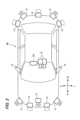
以下、本発明の一実施形態である制御装置100を含む車両システム1について、図面を参照して説明する。図面は、符号の向きに見るものとする。本明細書では説明を簡単かつ明確にするために、前後、左右の各方向は、図2に示す車両Mの運転者から見た方向に従って記載し、図面には、車両Mの前方をFr、後方をRr、左方をL、右方をR、として示す。The
<車両システム1の全体構成>
図1は、制御装置100を搭載した車両システム1の全体構成を示すブロック図である。図2は、車両システム1に含まれる車両Mの外観構成例を示す模式図である。車両Mは、例えば、二輪や三輪、四輪等の車両であり、その駆動源は、ディーゼルエンジンやガソリンエンジンなどの内燃機関、電動機、或いはこれらの組み合わせである。電動機は、内燃機関に連結された発電機による発電電力、或いは二次電池や燃料電池の放電電力を使用して動作する。図2では、車両Mが四輪車である例を示している。<Overall configuration of
Fig. 1 is a block diagram showing the overall configuration of a
車両システム1は、例えば、カメラ10と、レーダ装置12と、LIDAR(Light Detection and Ranging)14と、通信装置20と、HMI(Human Machine Interface)30と、車両センサ40と、運転者(ドライバ)モニタカメラ50と、ナビゲーション装置60と、MPU(Map Positioning Unit)70と、運転操作子80と、制御装置100と、走行駆動力出力装置200と、ブレーキ装置210と、ステアリング装置220と、を備える。これらの装置や機器は、CAN(Controller Area Network)通信線等の多重通信線やシリアル通信線、無線通信網等によって互いに接続されている。The
カメラ10は、例えば、CCD(Charge Coupled Device)やCMOS(Complementary Metal Oxide Semiconductor)等の撮像素子を利用したデジタルカメラである。カメラ10は、車両Mの任意の箇所に取り付けられる。例えば、図2に示すように、カメラ10は、車両Mの車室内におけるバックミラー(不図示)近傍、及び車両Mの車室外における右側ドア前部・左側ドア前部などに設けられる。カメラ10により撮像された車両Mの進行方向前方、右後側方、及び左後側方のそれぞれの画像情報(カメラ10の出力情報)は、制御装置100へ送られる。The
レーダ装置12は、車両Mの周辺にミリ波などの電波を放射するとともに、物体で反射された電波(反射波)を検出して、物体における電波の反射点の分布情報(複数の反射点のそれぞれの距離と方位)を取得する。電波としては、レーザ、マイクロ波、ミリ波、超音波などを適宜用いることができる。レーダ装置12は、車両Mの任意の箇所に取り付けられる。例えば、図2に示すように、レーダ装置12は、前側に3つ、後側に2つの5つ設けられている。レーダ装置12の出力情報は、制御装置100へ送られる。以下では、前側のレーダ装置12の出力情報を前方レーダ情報と記載する。The
LIDAR14は、車両Mの周辺に光(或いは光に近い波長の電磁波)を照射し、散乱光を測定する。LIDAR14は、発光から受光までの時間に基づいて、物体の有無、及び物体までの距離を検出する。照射される光は、例えば、パルス状のレーザ光である。LIDAR14は、車両Mの任意の箇所に取り付けられる。例えば、図2に示すように、LIDAR14は、前側に2つ、後側に3つの5つ設けられている。LIDAR14の出力情報は、制御装置100へ送られる。The LIDAR 14 irradiates light (or electromagnetic waves with a wavelength close to that of light) around the vehicle M and measures the scattered light. The LIDAR 14 detects the presence or absence of an object and the distance to the object based on the time between emitting and receiving the light. The irradiated light is, for example, a pulsed laser light. The LIDAR 14 is attached to any location on the vehicle M. For example, as shown in FIG. 2, five
通信装置20は、例えば、セルラー網やWi-Fi(登録商標)網、Bluetooth(登録商標)、DSRC(Dedicated Short Range Communication)などを利用して、車両Mの周辺に存在する他車両と通信し、或いは無線基地局を介して各種サーバ装置と通信する。The
HMI30は、車両Mの乗員に対して各種情報を提示すると共に、乗員による入力操作を受け付ける。HMI30は、各種表示装置、スピーカ、ブザー、タッチパネル、スイッチ、キーなどを含む。The HMI 30 presents various information to the occupants of the vehicle M and accepts input operations by the occupants. The HMI 30 includes various display devices, speakers, buzzers, touch panels, switches, keys, etc.
車両センサ40は、車両Mの速度を検出する車速センサ、加速度を検出する加速度センサ、鉛直軸回りの角速度を検出するヨーレートセンサ、車両Mの向きを検出する方位センサ等を含む。The
運転者モニタカメラ50は、例えば、CCDイメージセンサやCMOSイメージセンサ等の撮像素子を利用したデジタルカメラである。運転者モニタカメラ50は、車両Mの運転席に着座した乗員(以下、運転者)の頭部を正面から(顔面を撮像する向きで)撮像可能な位置及び向きで、車両Mにおける任意の箇所に取り付けられる。The
ナビゲーション装置60は、例えば、GNSS(Global Navigation Satellite System)受信機61と、ナビHMI62と、経路決定部63とを備える。ナビゲーション装置60は、HDD(Hard Disk Drive)やフラッシュメモリなどの記憶装置に第1地図情報64を保持している。The
GNSS受信機61は、GNSS衛星から受信した信号に基づいて、車両Mの位置を特定する。車両Mの位置は、車両センサ40の出力を利用したINS(Inertial Navigation System)によって特定又は補完されてもよい。The GNSS
ナビHMI62は、表示装置、スピーカ、タッチパネル、キーなどを含む。ナビHMI62は、前述したHMI30と一部又は全部が共通化されてもよい。The
経路決定部63は、例えば、GNSS受信機61により特定された車両Mの位置(或いは入力された任意の位置)から、ナビHMI62を用いて乗員により入力された目的地までの経路(以下、地図上経路)を、第1地図情報64を参照して決定する。第1地図情報64は、例えば、道路を示すリンクと、リンクによって接続されたノードとによって道路形状が表現された情報である。第1地図情報64は、道路の曲率やPOI(Point Of Interest)情報などを含んでもよい。地図上経路は、MPU70に出力される。The
ナビゲーション装置60は、地図上経路に基づいて、ナビHMI62を用いた経路案内を行ってもよい。ナビゲーション装置60は、通信装置20を介してナビゲーションサーバに現在位置と目的地を送信し、ナビゲーションサーバから地図上経路と同等の経路を取得してもよい。The
MPU70は、例えば、推奨車線決定部71を含み、HDDやフラッシュメモリなどの記憶装置に第2地図情報72を保持している。推奨車線決定部71は、ナビゲーション装置60から提供された地図上経路を複数のブロックに分割し(例えば、車両進行方向に関して100[m]毎に分割し)、第2地図情報72を参照してブロック毎に推奨車線を決定する。推奨車線決定部71は、例えば、左から何番目の車線を走行するといった決定を行う。推奨車線決定部71は、地図上経路に分岐箇所が存在する場合、車両Mが、分岐先に進行するための合理的な経路を走行できるように、推奨車線を決定する。The
第2地図情報72は、第1地図情報64よりも高精度な地図情報である。第2地図情報72は、例えば、車線の中央の情報あるいは車線の境界の情報等を含んでいる。また、第2地図情報72には、道路情報、交通規制情報、住所情報、施設情報、電話番号情報などが含まれてよい。第2地図情報72は、通信装置20が他装置と通信することにより、随時、アップデートされてよい。The
運転操作子80は、例えば、ステアリングホイール82の他、アクセルペダル、ブレーキペダル、シフトレバー、ウインカー、その他の操作子を含む。運転操作子80には、操作量あるいは操作の有無を検出するセンサが取り付けられており、その検出結果は、制御装置100、もしくは、走行駆動力出力装置200、ブレーキ装置210、及びステアリング装置220のうち一部又は全部に出力される。The driving
ステアリングホイール82は、必ずしも環状である必要は無く、異形ステアやジョイスティック、ボタンなどの形態であってもよい。ステアリングホイール82には、ステアリング把持センサ84が取り付けられている。ステアリング把持センサ84は、静電容量センサなどにより実現され、運転者がステアリングホイール82を把持しているか否かを検知可能な信号を制御装置100に出力する。The
制御装置100は、CPU(Central Processing Unit)などのプロセッサと、このプロセッサの動作に必要な記憶媒体と、を少なくとも含む。このプロセッサが、記憶媒体に記憶されたプログラム実行することにより、第1制御部120及び第2制御部160として機能する。制御装置100は、単一のプロセッサによって処理を行うものに限らず、複数のプロセッサによって処理を分担して行うものであってもよい。The
<第1制御部120及び第2制御部160の構成>
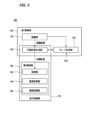
図3は、第1制御部120及び第2制御部160の構成の一例を示す図である。第1制御部120は、例えば、認識部130と、行動計画生成部140と、モード決定部150と、を備える。第1制御部120は、例えば、AI(Artificial Intelligence:人工知能)による機能と、予め与えられたモデルによる機能とを並行して実現する。<Configuration of
3 is a diagram showing an example of the configuration of the
例えば、「交差点を認識する」機能は、ディープラーニング等による交差点の認識と、予め与えられた条件(パターンマッチング可能な信号、道路標示などがある)に基づく認識とが並行して実行され、双方に対してスコア付けして総合的に評価することで実現されてよい。これによって、自動運転の信頼性が担保される。For example, the "intersection recognition" function may be realized by executing intersection recognition using deep learning or the like and recognition based on pre-given conditions (such as traffic lights and road markings that can be pattern-matched) in parallel, and then scoring both to comprehensively evaluate them. This ensures the reliability of autonomous driving.
認識部130は、例えば、車両Mが走行している走行環境を認識する。例えば、認識部130は、第2地図情報72から得られる道路区画線のパターン(例えば実線と破線の配列)と、カメラ10によって撮像された画像から認識される車両Mの周辺の道路区画線のパターンとを比較することで、車両Mの走行車線を認識する。なお、認識部130は、道路区画線に限らず、道路区画線や路肩、縁石、中央分離帯、ガードレールなどを含む走路境界(道路境界)を認識することで、走行車線を認識してもよい。この認識において、ナビゲーション装置60から取得される車両Mの位置やINSによる処理結果が加味されてもよい。また、認識部130は、一時停止線、障害物、赤信号、料金所、その他の道路事象を認識する。The
認識部130は、走行車線を認識する際に、走行車線に対する車両Mの位置や姿勢を認識する。認識部130は、例えば、車両Mの基準点の車線中央からの乖離、及び車両Mの進行方向の車線中央を連ねた線に対してなす角度を、走行車線に対する車両Mの相対位置及び姿勢として認識してもよい。これに代えて、認識部130は、走行車線のいずれかの側端部(道路区画線又は道路境界)に対する車両Mの基準点の位置などを、走行車線に対する車両Mの相対位置として認識してもよい。以下では、一例として、カメラ10の設置位置を基準点Pとする。When recognizing the travel lane, the
認識部130は、カメラ10、レーダ装置12、及びLIDAR14のうち一部又は全部の出力情報に基づいて、車両Mの周辺環境を認識する。例えば、認識部130は、車両Mの周辺にある物体の位置、及び物体の種別(動体か静止物か)等を認識する。物体の位置は、例えば、車両Mの代表点(重心や駆動軸中心など)を原点とした絶対座標(車両Mの代表点を通り且つ左右方向に平行なY軸(図6のY軸Ay)と、車両Mの代表点を通り且つ前後方向に平行なX軸(図6のX軸Ax)とで示されるXY平面)上の位置として認識され、各種の制御に使用される。The
車両Mの周辺にある物体としては、動体(周辺を走行する他車両等)と、静止物(植栽、壁、中央分離帯などの道路の境界を形成する物体、工事時や事故時に特有の設置物(コーン、ガードレール、看板、仮設信号機等)と、が挙げられる。認識部130は、車両Mの周辺における動体の認識処理として、レーダ装置12の出力に基づいて動体を認識する第1処理と、カメラ10の出力情報に基づいて動体を認識する第2処理と、をそれぞれ行う。Objects in the vicinity of vehicle M include moving objects (other vehicles traveling nearby, etc.) and stationary objects (objects that form road boundaries such as plants, walls, and median strips, as well as objects that are specifically installed during construction or accidents (cones, guardrails, signs, temporary traffic lights, etc.)). The
行動計画生成部140は、原則的には推奨車線決定部71により決定された推奨車線を走行し、更に、車両Mの周辺状況に対応できるように、車両Mが自動的に(運転者の操作に依らずに)将来走行する目標軌道を生成する。目標軌道は、例えば、速度要素を含んでいる。例えば、目標軌道は、車両Mの到達すべき地点(軌道点)を順に並べたものとして表現される。軌道点は、道なり距離で所定の走行距離(例えば数[m]程度)毎の車両Mの到達すべき地点であり、それとは別に、所定のサンプリング時間(例えば0コンマ数[sec]程度)毎の目標速度及び目標加速度が、目標軌道の一部として生成される。また、軌道点は、所定のサンプリング時間毎の、そのサンプリング時刻における車両Mの到達すべき位置であってもよい。この場合、目標速度や目標加速度の情報は軌道点の間隔で表現される。In principle, the action
行動計画生成部140は、目標軌道を生成するにあたり、自動運転のイベントを設定してもよい。自動運転のイベントには、定速走行イベント、低速追従走行イベント、車線変更イベント、分岐イベント、合流イベント、テイクオーバーイベントなどがある。行動計画生成部140は、起動させたイベントに応じた目標軌道を生成する。The behavior
モード決定部150は、車両Mの運転モードを、運転者に課されるタスクが異なる複数の運転モードのいずれかに決定する。また、モード決定部150は、決定した運転モード(以下、現運転モード)のタスクが運転者により実行されない場合に、よりタスクが重度な運転モードに車両Mの運転モードを変更する。モード決定部150は、車両Mの走行速度及び操舵の少なくともいずれかの制御の自動化モードを複数の運転モードの中から選択して設定する制御状態設定部の一例である。The
<運転モードの具体例>
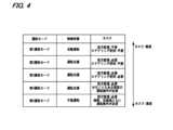
図4は、運転モードの具体例を示す図である。車両Mの運転モードには、例えば、第1運転モードから第5運転モードの5つのモードがある。制御状態すなわち車両Mの運転制御の自動化度合いは、第1運転モードが最も高く、次いで第2運転モード、第3運転モード、第4運転モードの順に低くなり、第5運転モードが最も低い。この逆に、運転者に課されるタスクは、第1運転モードが最も軽度であり、次いで第2運転モード、第3運転モード、第4運転モードの順に重度となり、第5運転モードが最も重度である。なお、第1運転モード以外の運転モードでは自動運転でない制御状態となるため、制御装置100としては自動運転の制御を終了し、運転支援又は手動運転に移行させるまでが責務である。以下、それぞれの運転モードの内容について例示する。<Examples of operation modes>
FIG. 4 is a diagram showing a specific example of the driving mode. The driving modes of the vehicle M include, for example, five modes, from the first driving mode to the fifth driving mode. The control state, i.e., the degree of automation of the driving control of the vehicle M, is highest in the first driving mode, followed by the second driving mode, the third driving mode, and the fourth driving mode, and is lowest in the fifth driving mode. Conversely, the task imposed on the driver is the lightest in the first driving mode, followed by the second driving mode, the third driving mode, and the fourth driving mode, and is the most severe in the fifth driving mode. Note that in driving modes other than the first driving mode, the control state is not automatic driving, so the responsibility of the
第1運転モードでは、自動運転の状態となり、運転者には、前方監視、ステアリングホイール82の把持のいずれも課されない。但し、第1運転モードであっても運転者は、制御装置100からの要求に応じて速やかに手動運転に移行できる体勢であることが要求される。なお、ここで言う自動運転とは、操舵、加減速のいずれも運転者の操作に依らずに制御されることをいう。前方とは、フロントウインドシールドを介して視認される車両Mの進行方向の空間を意味する。第1運転モードは、例えば、高速道路などの自動車専用道路において、所定速度以下(例えば60[km/h]程度)で車両Mが走行しており、追従対象の前走車両が存在するなどの条件が満たされる場合に実行可能な運転モードである。In the first driving mode, the vehicle is in an automatic driving state, and the driver is not required to monitor the road ahead or hold the
第2運転モードでは、運転支援の状態となり、運転者には、車両Mの前方を監視するタスク(以下、前方監視)が課されるが、ステアリングホイール82を把持するタスクは課されない。第3運転モードでは、運転支援の状態となり、運転者には前方監視のタスクと、ステアリングホイール82を把持するタスクが課される。第4運転モードは、車両Mの操舵と加減速のうち少なくとも一方に関して、ある程度の運転者による運転操作が必要な運転モードである。例えば、第4運転モードでは、ACC(Adaptive Cruise Control)やLKAS(Lane Keeping Assist System)といった運転支援が行われる。第5運転モードでは、操舵、加減速ともに運転者による運転操作が必要な手動運転の状態となる。第4運転モード、第5運転モードともに、当然ながら運転者には車両Mの前方を監視するタスクが課される。In the second driving mode, the vehicle is in a driving assistance state, and the driver is tasked with monitoring the front of the vehicle M (hereinafter, forward monitoring), but is not tasked with gripping the
図3に戻り、第2制御部160は、行動計画生成部140によって生成された目標軌道を、予定の時刻通りに車両Mが通過するように制御する。第2制御部160は、例えば、取得部162と、速度制御部164と、操舵制御部166と、を備える。Returning to FIG. 3, the
取得部162は、行動計画生成部140により生成された目標軌道(軌道点)の情報を取得し、メモリ(不図示)に記憶させる。速度制御部164は、メモリに記憶された目標軌道に付随する速度要素に基づいて、走行駆動力出力装置200(図1参照)又はブレーキ装置210(図1参照)を制御する。操舵制御部166は、メモリに記憶された目標軌道の曲がり具合に応じて、ステアリング装置220(図1参照)を制御する。速度制御部164及び操舵制御部166の処理は、例えば、フィードフォワード制御とフィードバック制御との組み合わせにより実現される。The
制御装置100において、行動計画生成部140と第2制御部160を合わせたものが走行制御部170を構成する。走行制御部170は、認識部130によって認識される車両Mの走行環境あるいは周辺環境等の認識結果に基づいて、車両Mにおける自動車線変更の制御を実行する。また、走行制御部170は、運転者による運転操作子80(例えばウインカーレバー)の操作に基づいて運転者の車線変更の意図を検出する。In the
走行制御部170は、車両Mの運転者による関与の度合いが異なる複数の車線変更態様の中から1つの車線変更態様を選択し、選択された車線変更態様に従って走行制御(車線変更制御ともいう)を行う。車両Mの運転者による関与の度合いが異なる複数の車線変更態様とは、自動化度合いが異なる複数の車線変更態様ということもできる。運転者による関与の度合いが小さいほど自動化度合いが高く、運転者による関与の度合いが大きいほど自動化度合いが低い。The driving
例えば、複数の車線変更態様は、以下の3つの自動車線変更の態様を含んでもよい。1つ目の自動車線変更は、車両Mの運転者が自ら車線変更を意図し、車両Mの運転者が車線変更の開始を指示する意図自動車線変更(ALC-カテゴリC)である。意図自動車線変更においては、車両Mの運転者が、他車両の走行状況、目的地への経路等を考慮して、車線変更すべきであるかどうかを判定する。車両Mの運転者は、車線変更すべきである場合には、運転操作子80を操作することにより、車両Mに対して車線変更の開始の指示を与える。走行制御部170は、この指示に基づいて、周囲の走行状況を考慮しつつ、実行可能なタイミングで自動車線変更を開始する。For example, the multiple lane change modes may include the following three automated lane change modes. The first type of automated lane change is an intentional automated lane change (ALC-category C) in which the driver of vehicle M intends to change lanes himself/herself and issues an instruction to start the lane change. In an intentional automated lane change, the driver of vehicle M determines whether or not to change lanes, taking into account the driving conditions of other vehicles, the route to the destination, etc. If the driver of vehicle M should change lanes, he/she issues an instruction to vehicle M to start a lane change by operating the driving
2つ目の自動車線変更は、走行制御部170が車線変更を提案し、車両Mの運転者が車線変更を承認する提案自動車線変更で(ALC-カテゴリD)ある。提案自動車線変更においては、走行制御部170が、他車両の走行状況、目的地への経路等に基づいて、車線変更すべきであるかどうかを判定する。走行制御部170は、車線変更すべきである場合に、運転者に対して車線変更を提案する。車両Mの運転者は、車線変更の提案を承認する場合には、承認スイッチを操作することにより、車両Mに対して車線変更の開始の指示を与える。承認スイッチは、承認専用のスイッチでもよいし、他の機能を兼用する操作子(一例としては運転操作子80)でもよい。走行制御部170は、この指示に基づいて、周囲の走行状況を考慮しつつ、実行可能なタイミングで自動車線変更を開始する。したがって、運転者が車線変更の提案を承認しない場合、すなわち運転操作子80を操作しない場合には、自動車線変更は実行されない。The second type of automated lane change is a proposed automated lane change (ALC-category D) in which the driving
3つ目の自動車線変更は、走行制御部170が車線変更を判断し、走行制御部170が車線変更の開始を決定する判断自動車線変更(ALC-カテゴリE)である。判断自動車線変更においては、走行制御部170が、他車両の走行状況、目的地への経路等に基づいて、車線変更すべきであるかどうかを判定する。走行制御部170は、車線変更すべきである場合には、周囲の走行状況を考慮して、実行可能なタイミングで自動車線変更を開始する。判断自動車線変更の場合、車両Mの運転者は、当該車線変更へ関与しない。The third type of automated lane change is a determined automated lane change (ALC-category E) in which the driving
制御装置100は、運転モードに応じた自動車線変更を実行する。例えば、制御装置100は、第1運転モードにおいて、判断自動車線変更を実行し得る。制御装置100は、第2運転モード、第3運転モード、及び第4運転モードにおいて、提案自動車線変更を実行し得る。制御装置100は、第3運転モード、及び第4運転モードにおいて、意図自動車線変更を実行し得る。制御装置100は、第5運転モードにおいて、いずれの自動車線変更も実行しない。The
図1に戻り、走行駆動力出力装置200は、車両が走行するための走行駆動力(トルク)を駆動輪に出力する。走行駆動力出力装置200は、例えば、内燃機関、電動機、及び変速機などの組み合わせと、これらを制御するECU(Electronic Control Unit)とを備える。ECUは、第2制御部160から入力される情報、或いは運転操作子80から入力される情報に従って、上記の構成要素を制御する。Returning to FIG. 1, the driving
ブレーキ装置210は、例えば、ブレーキキャリパーと、ブレーキキャリパーに油圧を伝達するシリンダと、シリンダに油圧を発生させる電動モータと、ブレーキECUとを備える。ブレーキECUは、第2制御部160から入力される情報、或いは運転操作子80から入力される情報に従って電動モータを制御し、制動操作に応じたブレーキトルクが各車輪に出力されるようにする。The
ステアリング装置220は、例えば、ステアリングECUと、電動モータとを備える。電動モータは、例えば、ラックアンドピニオン機構に力を作用させて転舵輪の向きを変更する。ステアリングECUは、第2制御部160から入力される情報、或いは運転操作子80から入力される情報に従って、電動モータを駆動し、転舵輪の向きを変更させる。The
<検出対象物体との位置関係の判定>
図5は、車両Mの周辺のうち認識部130によって認識が可能な領域を模式的に示す図である。図5には、カメラ10によって物体を検出可能な範囲10Aと、レーダ装置12によって物体を検出可能な範囲12Aとが示されている。図5に示すように、レーダ装置12は前後方向における検出範囲が広く、カメラ10は左右方向における検出範囲が広くなっている。したがって、車両Mとその周囲の検知対象物体としての他車両との前後方向の距離は、カメラ10の出力情報を用いるよりも、レーダ装置12の出力情報を用いた方が精度よく導出できる場合がある。また、車両Mと他車両との左右方向の距離は、レーダ装置12の出力情報を用いるよりも、カメラ10の出力情報を用いた方が精度よく導出できる場合がある。<Determination of Positional Relationship with Detection Target Object>
5 is a diagram showing a schematic view of an area around the vehicle M that can be recognized by the
図6は、車両Mと他車両MAとの位置関係を判定する方法を説明する模式図である。図6は、カメラ10からの画像情報と、前側のレーダ装置12からの前方レーダ情報のそれぞれに基づいて、共通の他車両MAが認識された状態を示している。Figure 6 is a schematic diagram illustrating a method for determining the positional relationship between vehicle M and another vehicle MA. Figure 6 shows a state in which a common vehicle MA is recognized based on both image information from the
第1制御部120は、画像情報に基づいて認識した他車両MAの特徴点として、前後方向における車両Mに近い側の第1端部(図6の例では後端部MRr)のうち、左右方向における一端部(図6の例では右後端部MR)と他端部(図6の例では左後端部ML)を検出する。第1制御部120は、他車両MAの特徴点として、前後方向における車両Mと遠い側の第2端部(図6の例では前端部MFr)のうち、左右方向における車両Mに近い側の特定端部(図6の例では左前端部MZ)を検出する。The
第1制御部120は、画像情報に基づいて検出した右後端部MRに基づいて、前後方向に対する車両Mと右後端部MRとを結ぶ方向のなす第1角度θR(基準点Pを通り且つ前後方向に延びる直線と、基準点Pと右後端部MRを結ぶ直線とのなす角度)を導出する。第1制御部120は、画像情報に基づいて検出した左後端部MLに基づいて、前後方向に対する車両Mと左後端部MLとを結ぶ方向のなす第2角度θL(基準点Pを通り且つ前後方向に延びる直線と、基準点Pと左後端部MLを結ぶ直線とのなす角度)を導出する。第1制御部120は、前方画像情報に基づいて検出した左前端部MZに基づいて、前後方向に対する車両Mと左前端部MZと結ぶ方向のなす第3角度θZ(基準点Pを通り且つ前後方向に延びる直線と、基準点Pと左前端部MZを結ぶ直線とのなす角度)を導出する。Based on the right rear end MR detected based on the image information, the
第1制御部120は、前方レーダ情報に基づいて、前後方向における他車両MAと車両Mの間の距離情報を取得する。第1制御部120は、距離情報として、基準点Pから後端部MRrまでの第1距離L1と、基準点Pから前端部MFrまでの第2距離L2と、を取得する。The
第1制御部120は、このようにして導出した各種情報を用いて下記式(A)と式(B)の演算を行うことで、車両Mと他車両MAの左右方向の距離情報(他車両MAの左端部までの距離YRと、他車両MAの右端部までの距離YL)を導出する。このようにして導出した距離情報を用いることで、他車両MAが車両Mの走行している車線の隣接車線を走行しているの否か、他車両MAがその隣接車線のさらに隣の車線を走行しているか否か等の判定が可能となり、この判定を利用した走行制御が可能となる。tanは、タンジェントを示す。The
YR=L1×tanθR ・・(A)
YL=L1×tanθL ・・(B) YR=L1×tanθR...(A)
YL=L1×tanθL...(B)
第1制御部120は、更に、下記式(C)の演算を行って、車両Mから他車両MAの右前端部までの距離YZを導出する。
YZ=L2×tanθZ ・・(C) The
YZ=L2×tanθZ...(C)
第1制御部120は、導出した距離YZと距離YLに基づいて、他車両MAの進行方向と車両Mの進行方向(前後方向と同義)とのなす角度を導出する。例えば、距離YZと距離YLが一致するときを角度=0度とすると、距離YZ<距離YLのときには、距離YZが小さくなるほど、角度がプラスの方向に大きくなり、距離YZ>距離YLのときには、距離YZが大きくなるほど、角度がマイナスの方向に大きくなる。The
第1制御部120は、例えば、距離YRと距離YLに基づいて他車両MAが隣接車線を走行中であると認識した場合には、更に、上記の角度を用いて、隣接車線から他車両MAが車両Mの走行中の車線に進入してくるか否かを判定する。例えば、上記角度が0よりも大きな閾値以上であれば、車両Mの前方に他車両MAが進入してくると判定し、上記角度が上記閾値未満であれば、車両Mの前方に他車両MAが進入してこないと判定する。このように、他車両MAの進入判定を行うことで、例えば、進入してくると判定したときには車間を保てるように速度を落とす等の走行制御が可能となる。For example, when the
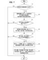
図7は、車両と他車両との位置関係を判定する際の第1制御部120の処理を説明するためのフローチャートである。このフローチャートは、画像情報と前方レーダ情報のそれぞれに基づいて同一の他車両MAが認識されたときの動作を示す。Figure 7 is a flowchart for explaining the processing of the
第1制御部120は、画像情報に基づいて認識した他車両MAの認識結果が正常であるか否かを判定する(ステップS1)。第1制御部120は、例えば、他車両MAの移動速度が閾値を超えている、又は、他車両MAの左右方向の幅が閾値を超えている等の場合には、認識結果が異常と判定する。The
第1制御部120は、認識結果が異常と判定した場合(ステップS1:NO)には、処理を終了する。第1制御部120は、認識結果が正常と判定した場合(ステップS1:YES)には、画像情報に基づいて、他車両MAの第1端部の両端部(図6の右後端部MRと左後端部ML)と、他車両MAの第2端部の特定端部(図6の左前端部MZ)と、を検出する(ステップS2)。If the
次に、第1制御部120は、ステップS2において第1端部の両端部を検出できたか否かを判定する(ステップS3)。画像情報に含まれる他車両MAの画像のうち、例えば、他車両MAの左後端部や右後端部が日光や障害物によって見えなくなることがあり、このような場合には、他車両MAの左後端部や右後端部を検出できない。このような場合にはステップS3の判定はNOとなる。ステップS3の判定がNOとなった場合(両端部の少なくとも一方が検出不可の状態)には、処理が終了される。Next, the
第1制御部120は、第1端部の両端部を検出できた場合(ステップS3:YES)には、第1端部の両端部と第2端部の特定端部に基づいて、前述した第1角度θR、第2角度θL、及び第3角度θZを導出する(ステップS4)。If the
次に、第1制御部120は、ステップS4で導出した第1角度θRと第2角度θLがそれぞれ所定範囲内にあるか否かを判定する(ステップS5)。この所定範囲は、車両Mの走行する車線の隣又はその更に隣の車線を走行する他車両がある場合に想定される範囲としてあらかじめ決められる。したがって、第1制御部120は、第1角度θRと第2角度θLの少なくとも一方が所定範囲を超えている場合には、何らかの異常により第1角度θRと第2角度θLの少なくとも一方の信頼性が低いと判断して、これら角度を用いた位置関係の判定を停止する。すなわち、第1制御部120は、第1角度θRと第2角度θLの少なくとも一方が所定範囲を超えている場合(ステップS5:NO)には、処理を終了する。Next, the
第1制御部120は、第1角度θRと第2角度θLのそれぞれが所定範囲内である場合(ステップS5:YES)には、前方レーダ情報に基づいて、前後方向における他車両MAと車両Mの間の距離情報(図6の第1距離L1、第2距離L2)を取得する(ステップS6)。If the first angle θR and the second angle θL are each within a predetermined range (step S5: YES), the
そして、第1制御部120は、ステップS6で取得した距離情報と、ステップS4で導出した角度情報とに基づいて、上述したように、車両Mと他車両MAとの位置関係を判定する(ステップS7)。その後、走行制御部170は、判定された位置関係に基づいて車両Mの走行制御を行う。Then, the
図6に示した第1距離L1や第2距離L2は、画像情報に基づいて導出することも可能である。例えば、撮像画像における他車両MAの上下方向の位置によって、他車両MAまでの前後方向の距離を推定できる。しかし、車両Mと他車両MAが走行している走路に勾配があると、撮像画像から推定できる他車両MAまでの前後方向の距離は誤差を含む可能性がある。一方、レーダ装置12に基づいて認識される他車両MAまでの距離は、走路に勾配があったとしても高精度に得られる。本形態では、第1制御部120が、画像情報に基づいて導出した角度情報(第1角度θR及び第2角度θL)と、前方レーダ情報に基づいて導出した距離情報(第1距離L1)に基づいて、距離YLと距離YRを導出する。画像情報からは距離の情報を直接求めていないため、走路に勾配があったとしても、距離YLと距離YRを高精度に導出可能となる。The first distance L1 and the second distance L2 shown in FIG. 6 can also be derived based on image information. For example, the longitudinal distance to the other vehicle MA can be estimated based on the vertical position of the other vehicle MA in the captured image. However, if there is a gradient on the road on which the vehicle M and the other vehicle MA are traveling, the longitudinal distance to the other vehicle MA that can be estimated from the captured image may contain an error. On the other hand, the distance to the other vehicle MA recognized based on the
また、本形態では、第1制御部120が、画像情報に基づいて導出した角度情報(第3角度θZ)と、前方レーダ情報に基づいて導出した距離情報(第2距離L2)に基づいて距離YZを導出し、距離YZと距離YLの比較により、他車両MAの進入角度を導出できる。距離YZも、画像情報からは距離の情報を直接求めていないため、走路に勾配があったとしても、高精度に導出可能となる。この結果、進入角度も高精度に導出でき、走行制御の信頼性を向上させることができる。In addition, in this embodiment, the
また、本形態では、第1制御部120が、第1角度θRと第2角度θLが所定範囲内である場合にのみ、ステップS7の判定を行うものとしている。これにより、他車両との位置関係をより高精度に判定することができる。In addition, in this embodiment, the
また、本形態では、第1制御部120が、他車両MAの左後端部と右後端部の少なくとも一方を検出できない場合には、ステップS7の判定を行わないものとしている。これにより、他車両との位置関係をより高精度に判定することができる。In addition, in this embodiment, if the
本明細書には少なくとも以下の事項が記載されている。なお、括弧内には、上記した実施形態において対応する構成要素等を示しているが、これに限定されるものではない。This specification describes at least the following items. Note that the corresponding components in the above-mentioned embodiment are shown in parentheses, but are not limited to these.
(1) 車両(車両M)の走行制御を行う制御装置(制御装置100)であって、
前記車両に設けられた撮像装置(カメラ10)及びレーダ装置(レーダ装置12)の出力情報を取得可能なプロセッサを備え、
前記プロセッサは、前記撮像装置の出力情報に基づいて、前記車両の周辺の検知対象物体(他車両MA)の前記車両の前後方向における前記車両に近い側の第1端部(後端部MRr)のうち、前記車両の左右方向における一端部(右後端部MR)と他端部(左後端部ML)を検出し、
前記一端部と前記他端部に基づいて、前記前後方向に対する前記車両と前記一端部を結ぶ方向のなす第1角度(第1角度θR)と、前記前後方向に対する前記車両と前記他端部を結ぶ方向のなす第2角度(第2角度θL)とを導出し、
前記レーダ装置の出力情報に基づいて、前記検知対象物体の前記第1端部と前記車両との第1距離(第1距離L1)を導出し、
前記第1角度と、前記第2角度と、前記第1距離と、に基づいて、前記車両と前記検知対象物体との位置関係を判定する、制御装置。 (1) A control device (control device 100) that controls driving of a vehicle (vehicle M),
A processor capable of acquiring output information of an imaging device (camera 10) and a radar device (radar device 12) provided on the vehicle,
The processor detects, based on output information from the imaging device, one end (right rear end MR) and the other end (left rear end ML) in a left-right direction of the vehicle out of a first end (rear end MRr) on a side closer to the vehicle in a front-rear direction of the vehicle of a detection target object (another vehicle MA) in the periphery of the vehicle;
deriving a first angle (first angle θR) formed in a direction connecting the vehicle and the one end with respect to the longitudinal direction, and a second angle (second angle θL) formed in a direction connecting the vehicle and the other end with respect to the longitudinal direction, based on the one end and the other end;
deriving a first distance (first distance L1) between the first end of the detection target object and the vehicle based on output information of the radar device;
A control device that determines a positional relationship between the vehicle and the detection target object based on the first angle, the second angle, and the first distance.
(1)によれば、検知対象物体との位置関係を高精度に判定することができるため、走行制御の安全性を向上させることができる。According to (1), the positional relationship with the detection target object can be determined with high accuracy, thereby improving the safety of driving control.
(2) (1)に記載の制御装置であって、
前記プロセッサは、前記撮像装置の出力情報に基づいて、前記検知対象物体の前記前後方向における前記車両から遠い側の第2端部(前端部MFr)のうち、前記左右方向の前記車両に近い側の端部である特定端部(左前端部MZ)を検出し、
前記特定端部に基づいて、前記前後方向に対する前記車両と前記特定端部を結ぶ方向のなす第3角度(第3角度θZ)を導出し、
前記レーダ装置の出力情報に基づいて、前記検知対象物体の前記第2端部と前記車両との第2距離(第2距離L2)を導出し、
前記第1角度と、前記第2角度と、前記第1距離と、前記第3角度と、前記第2距離とに基づいて前記位置関係を判定する、制御装置。 (2) The control device according to (1),
The processor detects a specific end (left front end MZ) that is an end closer to the vehicle in the left-right direction out of a second end (front end MFr) of the detection target object that is farther from the vehicle in the front-rear direction based on output information of the imaging device,
Deriving a third angle (third angle θZ) formed by a direction connecting the vehicle and the specific end with respect to the longitudinal direction based on the specific end;
deriving a second distance (second distance L2) between the second end of the detection target object and the vehicle based on output information of the radar device;
A control device that determines the positional relationship based on the first angle, the second angle, the first distance, the third angle, and the second distance.
(2)によれば、検知対象物体との位置関係をより高精度に判定することができる。According to (2), the positional relationship with the detection target object can be determined with higher accuracy.
(3) (2)に記載の制御装置であって、
前記プロセッサは、前記位置関係として、前記検知対象物体の進行方向と前記車両の進行方向とのなす角度を判定し、前記角度に基づいて、前記車両の走行している第1車線の隣の第2車線から前記検知対象物体が前記第1車線に進入することを判定する、制御装置。 (3) The control device according to (2),
The processor determines the angle between the direction of travel of the detected object and the direction of travel of the vehicle as the positional relationship, and determines that the detected object will enter the first lane from a second lane adjacent to the first lane in which the vehicle is traveling based on the angle.
(3)によれば、隣接車線を走行する他車両が車両の前方に進入するかどうかを高精度に判定することができ、走行制御の信頼性を高めることができる。(3) According to this, it is possible to determine with high accuracy whether another vehicle traveling in an adjacent lane will enter in front of the vehicle, thereby improving the reliability of driving control.
(4) (1)から(3)のいずれかに記載の制御装置であって、
前記プロセッサは、前記第1角度と前記第2角度が所定範囲内である場合に前記判定を行う、制御装置。 (4) The control device according to any one of (1) to (3),
The processor performs the determination when the first angle and the second angle are within a predetermined range.
(4)によれば、検知対象物体との位置関係をより高精度に判定することができる。According to (4), the positional relationship with the detection target object can be determined with higher accuracy.
(5) (1)から(4)のいずれかに記載の制御装置であって、
前記プロセッサは、前記一端部と前記他端部の少なくとも一方が検出不可の場合には、前記判定を停止する、制御装置。 (5) The control device according to any one of (1) to (4),
The processor stops the determination when at least one of the one end and the other end cannot be detected.
(5)によれば、検知対象物体との位置関係をより高精度に判定することができる。According to (5), the positional relationship with the detection target object can be determined with higher accuracy.
100 制御装置
10 カメラ
12 レーダ装置
M 車両100
Claims (5)
Translated fromJapanese前記車両に設けられた撮像装置及びレーダ装置の出力情報を取得可能なプロセッサを備え、
前記プロセッサは、
前記撮像装置の出力情報に基づいて、前記車両の周辺の検知対象物体の前記車両の前後方向における前記車両に近い側の第1端部のうち、前記車両の左右方向における一端部と他端部を検出し、
前記一端部と前記他端部に基づいて、前記前後方向に対する前記車両の基準点を通り且つ前記前後方向に延びる直線と前記一端部を結ぶ方向のなす第1角度θRと、前記前後方向に対する前記車両の基準点を通り且つ前記前後方向に延びる直線と前記他端部を結ぶ方向のなす第2角度θLとを導出し、
前記レーダ装置の出力情報に基づいて、前記検知対象物体の前記第1端部と前記車両との前記前後方向の第1距離L1を導出し、
前記第1角度θRと、前記第2角度θLと、前記第1距離L1と、に基づいて、前記車両と前記検知対象物体との位置関係を示す情報として、前記車両と前記検知対象物体の前記一端部との左右方向の距離情報YR、及び前記車両と前記検知対象物体の前記他端部との左右方向の距離情報YLを下記式(A)及び(B)を用いて導出する、
YR=L1×tanθR ・・(A)
YL=L1×tanθL ・・(B)
制御装置。 A control device for controlling driving of a vehicle,
A processor capable of acquiring output information of an imaging device and a radar device provided in the vehicle,
The processor,
detecting one end and another end in a left-right direction of the vehicle of a first end portion of a detection target object in a front-rear direction of the vehicle, the first end portion being closer to the vehicle than the other end portion of the detection target object in a front-rear direction of the vehicle, based on output information from the imaging device;
Based on the one end and the other end, a first angleθR formed by adirection connecting the one end and a straight line passing through a reference point of the vehicle with respect to the longitudinal direction and extending in the longitudinal direction, and a second angleθL formedby a direction connecting the other end and a straight line passing through a reference point of the vehicle with respect to the longitudinal direction and extending in the longitudinal direction ,
deriving a first distanceL1in the front-rear direction between the first end of the detection target object and the vehicle based on output information of the radar device;
Based on the first angleθR , the second angleθL , and the first distanceL1 , deriving,as information indicating a positional relationship between the vehicle and the detection target object, distance information YR in the left-right direction between the vehicle and the one end of the detection target object and distance information YL in the left-right direction between the vehicle and the other end of the detection target object using the following equations (A) and (B) :
YR=L1×tanθR...(A)
YL=L1×tanθL...(B)
Control device.
前記プロセッサは、前記撮像装置の出力情報に基づいて、前記検知対象物体の前記前後方向における前記車両から遠い側の第2端部のうち、前記左右方向の前記車両に近い側の端部である特定端部を検出し、
前記特定端部に基づいて、前記前後方向に対する前記車両の基準点を通り且つ前記前後方向に延びる直線と前記特定端部を結ぶ方向のなす第3角度θZを導出し、
前記レーダ装置の出力情報に基づいて、前記検知対象物体の前記第2端部と前記車両との前記前後方向の第2距離L2を導出し、
前記第1角度θRと、前記第2角度θLと、前記第1距離L1と、前記第3角度θZと、前記第2距離L2に基づいて、前記位置関係を示す情報として、前記車両と前記検知対象物体の前記特定端部との左右方向の距離情報YZを下記式(C)を用いて導出する、
YZ=L2×tanθZ ・・(C)
制御装置。 The control device according to claim 1 ,
The processor detects a specific end portion of the second end portion of the detection target object that is farther from the vehicle in the front-rear direction based on output information of the imaging device, the specific end portion being an end portion closer to the vehicle in the left-right direction;
Deriving a third angleθZ between a linepassing through a reference point of the vehicle with respect to the longitudinal direction and extending in the longitudinal direction and a direction connecting the specific end portion, based on the specific end portion;
deriving a second distanceL2in the front-rear direction between the second end of the detection target object and the vehicle based on output information of the radar device;
Based on the first angleθR , the second angleθL , the first distanceL1 , the third angleθZ , and the second distanceL2 ,distance information YZ in the left-right direction between the vehicle and the specific end of the detection target object is derived using the following formula (C) as information indicating the positional relationship.
YZ=L2×tanθZ...(C)
Control device.
前記プロセッサは、前記位置関係として、前記検知対象物体の進行方向と前記車両の進行方向とのなす角度を判定し、前記角度に基づいて、前記車両の走行している第1車線の隣の第2車線から前記検知対象物体が前記第1車線に進入することを判定する、制御装置。 The control device according to claim 2,
The processor determines the angle between the direction of travel of the detected object and the direction of travel of the vehicle as the positional relationship, and determines that the detected object will enter the first lane from a second lane adjacent to the first lane in which the vehicle is traveling based on the angle.
前記プロセッサは、前記第1角度と前記第2角度が所定範囲内である場合に前記位置関係を示す情報の導出を行う、制御装置。 The control device according to claim 1or 2 ,
The processorderives information indicating the positional relationship when the first angle and the second angle are within a predetermined range.
前記プロセッサは、前記一端部と前記他端部の少なくとも一方が検出不可の場合には、
前記位置関係を示す情報の導出を停止する、制御装置。 The control device according to claim 1or 2 ,
When at least one of the one end and the other end cannot be detected,
The control device stopsderiving the information indicating the positional relationship .
Priority Applications (3)
| Application Number | Priority Date | Filing Date | Title |
|---|---|---|---|
| JP2023048320AJP7653463B2 (en) | 2023-03-24 | 2023-03-24 | Control device |
| CN202410219011.2ACN118683558A (en) | 2023-03-24 | 2024-02-27 | Controls |
| US18/590,988US20240319362A1 (en) | 2023-03-24 | 2024-02-29 | Control device |
Applications Claiming Priority (1)
| Application Number | Priority Date | Filing Date | Title |
|---|---|---|---|
| JP2023048320AJP7653463B2 (en) | 2023-03-24 | 2023-03-24 | Control device |
Publications (2)
| Publication Number | Publication Date |
|---|---|
| JP2024136992A JP2024136992A (en) | 2024-10-04 |
| JP7653463B2true JP7653463B2 (en) | 2025-03-28 |
Family
ID=92765496
Family Applications (1)
| Application Number | Title | Priority Date | Filing Date |
|---|---|---|---|
| JP2023048320AActiveJP7653463B2 (en) | 2023-03-24 | 2023-03-24 | Control device |
Country Status (3)
| Country | Link |
|---|---|
| US (1) | US20240319362A1 (en) |
| JP (1) | JP7653463B2 (en) |
| CN (1) | CN118683558A (en) |
Citations (4)
| Publication number | Priority date | Publication date | Assignee | Title |
|---|---|---|---|---|
| JP2008310585A (en) | 2007-06-14 | 2008-12-25 | Toyota Motor Corp | Vehicle periphery monitoring device |
| JP2018206305A (en) | 2017-06-09 | 2018-12-27 | 株式会社Subaru | Outside-vehicle environment recognition device and outside-vehicle environment recognition method |
| JP2020122772A (en) | 2019-01-31 | 2020-08-13 | 株式会社デンソー | Object determination device |
| JP2022081350A (en) | 2020-11-19 | 2022-05-31 | 株式会社デンソー | Driving support device |
- 2023
- 2023-03-24JPJP2023048320Apatent/JP7653463B2/enactiveActive
- 2024
- 2024-02-27CNCN202410219011.2Apatent/CN118683558A/enactivePending
- 2024-02-29USUS18/590,988patent/US20240319362A1/enactivePending
Patent Citations (4)
| Publication number | Priority date | Publication date | Assignee | Title |
|---|---|---|---|---|
| JP2008310585A (en) | 2007-06-14 | 2008-12-25 | Toyota Motor Corp | Vehicle periphery monitoring device |
| JP2018206305A (en) | 2017-06-09 | 2018-12-27 | 株式会社Subaru | Outside-vehicle environment recognition device and outside-vehicle environment recognition method |
| JP2020122772A (en) | 2019-01-31 | 2020-08-13 | 株式会社デンソー | Object determination device |
| JP2022081350A (en) | 2020-11-19 | 2022-05-31 | 株式会社デンソー | Driving support device |
Also Published As
| Publication number | Publication date |
|---|---|
| CN118683558A (en) | 2024-09-24 |
| US20240319362A1 (en) | 2024-09-26 |
| JP2024136992A (en) | 2024-10-04 |
Similar Documents
| Publication | Publication Date | Title |
|---|---|---|
| JP7194224B2 (en) | VEHICLE CONTROL DEVICE, VEHICLE CONTROL METHOD, AND PROGRAM | |
| JP7464688B2 (en) | Vehicle control device, vehicle control method, and program | |
| JP2022103505A (en) | Vehicle control devices, vehicle control methods, and programs | |
| JP7203884B2 (en) | VEHICLE CONTROL DEVICE, VEHICLE CONTROL METHOD, AND PROGRAM | |
| JP2022096236A (en) | Vehicle control devices, vehicle control methods, and programs | |
| JP7308880B2 (en) | VEHICLE CONTROL DEVICE, VEHICLE CONTROL METHOD, AND PROGRAM | |
| JP7611741B2 (en) | MOBILE BODY CONTROL DEVICE, MOBILE BODY CONTROL METHOD, AND PROGRAM | |
| US12304490B2 (en) | Control device | |
| JP7470157B2 (en) | Vehicle control device, vehicle control method, and program | |
| JP7458459B2 (en) | Vehicle control device, vehicle control method, and program | |
| JP7376634B2 (en) | Vehicle control device, vehicle control method, and program | |
| JP7075550B1 (en) | Vehicle control devices, vehicle control methods, and programs | |
| JP7186210B2 (en) | VEHICLE CONTROL DEVICE, VEHICLE CONTROL METHOD, AND PROGRAM | |
| JP7048832B1 (en) | Vehicle control devices, vehicle control methods, and programs | |
| JP7653463B2 (en) | Control device | |
| WO2022144974A1 (en) | Vehicle control device, vehicle control method, and program | |
| JP7398498B2 (en) | Control device | |
| JP7398497B2 (en) | Control device | |
| JP7731312B2 (en) | Vehicle control device, vehicle control method, and program | |
| JP7748907B2 (en) | Vehicle control device, vehicle control method, and program | |
| JP7561800B2 (en) | Vehicle control device, vehicle control method, and program | |
| CN117584963A (en) | Vehicle control device, vehicle control method and storage medium |
Legal Events
| Date | Code | Title | Description |
|---|---|---|---|
| A621 | Written request for application examination | Free format text:JAPANESE INTERMEDIATE CODE: A621 Effective date:20231124 | |
| A131 | Notification of reasons for refusal | Free format text:JAPANESE INTERMEDIATE CODE: A131 Effective date:20241224 | |
| A521 | Request for written amendment filed | Free format text:JAPANESE INTERMEDIATE CODE: A523 Effective date:20250207 | |
| TRDD | Decision of grant or rejection written | ||
| A01 | Written decision to grant a patent or to grant a registration (utility model) | Free format text:JAPANESE INTERMEDIATE CODE: A01 Effective date:20250311 | |
| A61 | First payment of annual fees (during grant procedure) | Free format text:JAPANESE INTERMEDIATE CODE: A61 Effective date:20250317 | |
| R150 | Certificate of patent or registration of utility model | Ref document number:7653463 Country of ref document:JP Free format text:JAPANESE INTERMEDIATE CODE: R150 |