JP7652489B2 - Plasma processing method and plasma processing apparatus - Google Patents
Plasma processing method and plasma processing apparatusDownload PDFInfo
- Publication number
- JP7652489B2 JP7652489B2JP2021147135AJP2021147135AJP7652489B2JP 7652489 B2JP7652489 B2JP 7652489B2JP 2021147135 AJP2021147135 AJP 2021147135AJP 2021147135 AJP2021147135 AJP 2021147135AJP 7652489 B2JP7652489 B2JP 7652489B2
- Authority
- JP
- Japan
- Prior art keywords
- plasma processing
- electrostatic chuck
- temperature
- substrate
- gas
- Prior art date
- Legal status (The legal status is an assumption and is not a legal conclusion. Google has not performed a legal analysis and makes no representation as to the accuracy of the status listed.)
- Active
Links
- 238000012545processingMethods0.000titleclaimsdescription105
- 238000003672processing methodMethods0.000titleclaimsdescription31
- 239000007789gasSubstances0.000claimsdescription155
- 239000000758substrateSubstances0.000claimsdescription138
- 238000000034methodMethods0.000claimsdescription34
- 238000012546transferMethods0.000claimsdescription19
- 239000011261inert gasSubstances0.000claimsdescription6
- 230000000977initiatory effectEffects0.000claims2
- 230000000087stabilizing effectEffects0.000claims2
- 230000007423decreaseEffects0.000description24
- 238000013508migrationMethods0.000description22
- 230000005012migrationEffects0.000description22
- 238000001179sorption measurementMethods0.000description13
- 238000010586diagramMethods0.000description9
- 230000000694effectsEffects0.000description7
- 239000000919ceramicSubstances0.000description6
- 239000000463materialSubstances0.000description6
- 238000004891communicationMethods0.000description4
- 239000001307heliumSubstances0.000description4
- 229910052734heliumInorganic materials0.000description4
- SWQJXJOGLNCZEY-UHFFFAOYSA-Nhelium atomChemical compound[He]SWQJXJOGLNCZEY-UHFFFAOYSA-N0.000description4
- 239000002245particleSubstances0.000description4
- 230000010287polarizationEffects0.000description4
- 230000002950deficientEffects0.000description3
- 230000006870functionEffects0.000description3
- BSYNRYMUTXBXSQ-UHFFFAOYSA-NAspirinChemical compoundCC(=O)OC1=CC=CC=C1C(O)=OBSYNRYMUTXBXSQ-UHFFFAOYSA-N0.000description2
- 238000000231atomic layer depositionMethods0.000description2
- 238000001514detection methodMethods0.000description2
- 238000009792diffusion processMethods0.000description2
- 238000009616inductively coupled plasmaMethods0.000description2
- 238000009832plasma treatmentMethods0.000description2
- 230000001105regulatory effectEffects0.000description2
- 238000004544sputter depositionMethods0.000description2
- 239000000853adhesiveSubstances0.000description1
- 230000001070adhesive effectEffects0.000description1
- 238000005513bias potentialMethods0.000description1
- 230000015572biosynthetic processEffects0.000description1
- 239000012267brineSubstances0.000description1
- 230000001276controlling effectEffects0.000description1
- 238000001816coolingMethods0.000description1
- 238000005516engineering processMethods0.000description1
- 238000005530etchingMethods0.000description1
- 239000013529heat transfer fluidSubstances0.000description1
- 238000012544monitoring processMethods0.000description1
- HPALAKNZSZLMCH-UHFFFAOYSA-Msodium;chloride;hydrateChemical compoundO.[Na+].[Cl-]HPALAKNZSZLMCH-UHFFFAOYSA-M0.000description1
- 239000007787solidSubstances0.000description1
Images


Classifications
- H—ELECTRICITY
- H01—ELECTRIC ELEMENTS
- H01J—ELECTRIC DISCHARGE TUBES OR DISCHARGE LAMPS
- H01J37/00—Discharge tubes with provision for introducing objects or material to be exposed to the discharge, e.g. for the purpose of examination or processing thereof
- H01J37/32—Gas-filled discharge tubes
- H01J37/32431—Constructional details of the reactor
- H01J37/3244—Gas supply means
- H01J37/32449—Gas control, e.g. control of the gas flow
- H—ELECTRICITY
- H01—ELECTRIC ELEMENTS
- H01J—ELECTRIC DISCHARGE TUBES OR DISCHARGE LAMPS
- H01J37/00—Discharge tubes with provision for introducing objects or material to be exposed to the discharge, e.g. for the purpose of examination or processing thereof
- H01J37/32—Gas-filled discharge tubes
- H01J37/32431—Constructional details of the reactor
- H01J37/32697—Electrostatic control
- H01J37/32706—Polarising the substrate
- H—ELECTRICITY
- H01—ELECTRIC ELEMENTS
- H01J—ELECTRIC DISCHARGE TUBES OR DISCHARGE LAMPS
- H01J37/00—Discharge tubes with provision for introducing objects or material to be exposed to the discharge, e.g. for the purpose of examination or processing thereof
- H01J37/32—Gas-filled discharge tubes
- H01J37/32431—Constructional details of the reactor
- H01J37/32715—Workpiece holder
- H01J37/32724—Temperature
- H—ELECTRICITY
- H01—ELECTRIC ELEMENTS
- H01J—ELECTRIC DISCHARGE TUBES OR DISCHARGE LAMPS
- H01J37/00—Discharge tubes with provision for introducing objects or material to be exposed to the discharge, e.g. for the purpose of examination or processing thereof
- H01J37/32—Gas-filled discharge tubes
- H01J37/32917—Plasma diagnostics
- H01J37/32935—Monitoring and controlling tubes by information coming from the object and/or discharge
- H01J37/32981—Gas analysis
Landscapes
- Engineering & Computer Science (AREA)
- Physics & Mathematics (AREA)
- Plasma & Fusion (AREA)
- Chemical & Material Sciences (AREA)
- Analytical Chemistry (AREA)
- Container, Conveyance, Adherence, Positioning, Of Wafer (AREA)
- Drying Of Semiconductors (AREA)
- Condensed Matter Physics & Semiconductors (AREA)
- General Physics & Mathematics (AREA)
- Manufacturing & Machinery (AREA)
- Computer Hardware Design (AREA)
- Microelectronics & Electronic Packaging (AREA)
- Power Engineering (AREA)
Description
Translated fromJapanese本開示は、プラズマ処理方法及びプラズマ処理装置に関する。This disclosure relates to a plasma processing method and a plasma processing apparatus.
静電チャックが高温の環境下では、プラズマ処理期間が長くなると、静電チャックを構成する誘電膜の誘電体への電荷のマイグレーションが生じて静電チャックの吸着力が低下する現象が発生する(例えば、特許文献1参照)。When the electrostatic chuck is in a high-temperature environment, if the plasma processing period is extended, migration of charge into the dielectric of the dielectric film that constitutes the electrostatic chuck occurs, resulting in a decrease in the adhesive force of the electrostatic chuck (see, for example, Patent Document 1).
本開示は、マイグレーションによる静電チャックの吸着力の低下を抑制できる技術を提供する。This disclosure provides a technology that can suppress the decrease in the adsorption force of an electrostatic chuck caused by migration.
本開示の一の態様によれば、(a)プラズマ処理チャンバ内に配置された第1温度の静電チャックに基板を載置する工程と、(b)前記基板を前記静電チャックに静電吸着する工程と、(c)前記基板と前記静電チャックの間に伝熱ガスの供給を開始する工程と、(d)前記伝熱ガスの流量又は前記基板と前記静電チャックの間の圧力を検出する工程と、(e)前記流量又は前記圧力が所定の閾値を超過しているか否かを判定する工程と、(f)前記判定の結果に基づき、前記静電チャックを前記第1温度より高い第2温度に昇温させる工程と、(g)前記プラズマ処理チャンバ内にプラズマを生成する工程と、を有する、プラズマ処理方法が提供される。According to one aspect of the present disclosure, there is provided a plasma processing method comprising the steps of: (a) placing a substrate on an electrostatic chuck at a first temperature disposed in a plasma processing chamber; (b) electrostatically attracting the substrate to the electrostatic chuck; (c) starting the supply of a heat transfer gas between the substrate and the electrostatic chuck; (d) detecting the flow rate of the heat transfer gas or the pressure between the substrate and the electrostatic chuck; (e) determining whether the flow rate or the pressure exceeds a predetermined threshold value; (f) raising the temperature of the electrostatic chuck to a second temperature higher than the first temperature based on the result of the determination; and (g) generating a plasma in the plasma processing chamber.
一の側面によれば、マイグレーションによる静電チャックの吸着力の低下を抑制できる。According to one aspect, it is possible to suppress a decrease in the adsorption force of the electrostatic chuck due to migration.
以下、図面を参照して本開示を実施するための形態について説明する。各図面において、同一構成部分には同一符号を付し、重複した説明を省略する場合がある。Below, a description will be given of a mode for carrying out the present disclosure with reference to the drawings. In each drawing, the same components are given the same reference numerals, and duplicate descriptions may be omitted.
[プラズマ処理システム]
一実施形態において、図1に示すプラズマ処理システムは、プラズマ処理装置1及び制御部2を含む。プラズマ処理装置1は、プラズマ処理チャンバ10、基板支持部11及びプラズマ生成部12を含む。プラズマ処理チャンバ10は、プラズマ処理空間を有する。また、プラズマ処理チャンバ10は、少なくとも1つの処理ガスをプラズマ処理空間に供給するための少なくとも1つのガス供給口と、プラズマ処理空間からガスを排出するための少なくとも1つのガス排出口とを有する。ガス供給口は、後述するガス供給部20に接続され、ガス排出口は、後述する排気システム40に接続される。基板支持部11は、プラズマ処理空間内に配置され、基板を支持するための基板支持面を有する。 [Plasma Processing System]
In one embodiment, the plasma processing system shown in Fig. 1 includes a plasma processing apparatus 1 and a control unit 2. The plasma processing apparatus 1 includes a
プラズマ生成部12は、プラズマ処理空間内に供給された少なくとも1つの処理ガスからプラズマを生成するように構成される。プラズマ処理空間において形成されるプラズマは、容量結合プラズマ(CCP:Capacitively Coupled Plasma)、誘導結合プラズマ(ICP:Inductively Coupled Plasma)、ECRプラズマ(Electron-Cyclotron-resonance plasma)、ヘリコン波励起プラズマ(HWP:Helicon Wave Plasma)、又は、表面波プラズマ(SWP:Surface Wave Plasma)等であってもよい。また、AC(Alternating Current)プラズマ生成部及びDC(Direct Current)プラズマ生成部を含む、種々のタイプのプラズマ生成部が用いられてもよい。一実施形態において、ACプラズマ生成部で用いられるAC信号(AC電力)は、100kHz~10GHzの範囲内の周波数を有する。従って、AC信号は、RF(Radio Frequency)信号及びマイクロ波信号を含む。一実施形態において、RF信号は、200kHz~150MHzの範囲内の周波数を有する。The
制御部2は、本開示において述べられる種々の工程をプラズマ処理装置1に実行させるコンピュータ実行可能な命令を処理する。制御部2は、ここで述べられる種々の工程を実行するようにプラズマ処理装置1の各要素を制御するように構成され得る。一実施形態において、制御部2の一部又は全てがプラズマ処理装置1に含まれてもよい。制御部2は、例えばコンピュータ2aを含んでもよい。コンピュータ2aは、例えば、処理部(CPU:Central Processing Unit)2a1、記憶部2a2、及び通信インターフェース2a3を含んでもよい。処理部2a1は、記憶部2a2に格納されたプログラム及びレシピに基づいて種々の制御動作を行うように構成され得る。記憶部2a2は、RAM(Random Access Memory)、ROM(Read Only Memory)、HDD(Hard Disk Drive)、SSD(Solid State Drive)、又はこれらの組み合わせを含んでもよい。通信インターフェース2a3は、LAN(Local Area Network)等の通信回線を介してプラズマ処理装置1との間で通信してもよい。The control unit 2 processes computer-executable instructions that cause the plasma processing apparatus 1 to perform various processes described in this disclosure. The control unit 2 may be configured to control each element of the plasma processing apparatus 1 to perform various processes described herein. In one embodiment, a part or all of the control unit 2 may be included in the plasma processing apparatus 1. The control unit 2 may include, for example, a
次に、図2を参照しながらプラズマ処理装置1の一例としての容量結合型のプラズマ処理装置1の構成例について説明する。プラズマ処理装置1は、プラズマ処理チャンバ10、ガス供給部20、電源30及び排気システム40を含む。また、プラズマ処理装置1は、基板支持部11及びガス導入部を含む。ガス導入部は、少なくとも1つの処理ガスをプラズマ処理チャンバ10内に導入するように構成される。ガス導入部は、シャワーヘッド13を含む。基板支持部11は、プラズマ処理チャンバ10内に配置される。シャワーヘッド13は、基板支持部11の上方に配置される。一実施形態において、シャワーヘッド13は、プラズマ処理チャンバ10の天部(ceiling)の少なくとも一部を構成する。プラズマ処理チャンバ10は、シャワーヘッド13、プラズマ処理チャンバ10の側壁10a及び基板支持部11により規定されたプラズマ処理空間10sを有する。側壁10aは接地される。シャワーヘッド13及び基板支持部11は、プラズマ処理チャンバ10筐体とは電気的に絶縁される。Next, referring to FIG. 2, a configuration example of a capacitively coupled plasma processing apparatus 1 will be described as an example of the plasma processing apparatus 1. The plasma processing apparatus 1 includes a
基板支持部11は、本体部111及びリングアセンブリ112を含む。本体部111は、基板(ウェハ)Wを支持するための中央領域(基板支持面)111aと、リングアセンブリ112を支持するための環状領域(リング支持面)111bとを有する。本体部111の環状領域111bは、平面視で本体部111の中央領域111aを囲んでいる。基板Wは、本体部111の中央領域111a上に配置され、リングアセンブリ112は、本体部111の中央領域111a上の基板Wを囲むように本体部111の環状領域111b上に配置される。一実施形態において、本体部111は、基台及び静電チャックを含む。基台は、導電性部材を含む。基台の導電性部材は下部電極として機能する。静電チャックは、基台の上に配置される。静電チャックの上面は、基板支持面111aを有する。リングアセンブリ112は、1又は複数の環状部材を含む。1又は複数の環状部材のうち少なくとも1つはエッジリングである。また、図示は省略するが、基板支持部11は、静電チャック、リングアセンブリ112及び基板のうち少なくとも1つをターゲット温度に調節するように構成される温調モジュールを含んでもよい。温調モジュールは、ヒータ、伝熱媒体、流路、又はこれらの組み合わせを含んでもよい。流路には、ブラインやガスのような伝熱流体が流れる。また、基板支持部11は、基板Wの裏面と基板支持面111aとの間に伝熱ガスを供給するように構成された伝熱ガス供給部を含んでもよい。The
シャワーヘッド13は、ガス供給部20からの少なくとも1つの処理ガスをプラズマ処理空間10s内に導入するように構成される。シャワーヘッド13は、少なくとも1つのガス供給口13a、少なくとも1つのガス拡散室13b、及び複数のガス導入口13cを有する。ガス供給口13aに供給された処理ガスは、ガス拡散室13bを通過して複数のガス導入口13cからプラズマ処理空間10s内に導入される。また、シャワーヘッド13は、導電性部材を含む。シャワーヘッド13の導電性部材は上部電極として機能する。なお、ガス導入部は、シャワーヘッド13に加えて、側壁10aに形成された1又は複数の開口部に取り付けられる1又は複数のサイドガス注入部(SGI:Side Gas Injector)を含んでもよい。The
ガス供給部20は、少なくとも1つのガスソース21及び少なくとも1つの流量制御器22を含んでもよい。一実施形態において、ガス供給部20は、少なくとも1つの処理ガスを、それぞれに対応のガスソース21からそれぞれに対応の流量制御器22を介してシャワーヘッド13に供給するように構成される。各流量制御器22は、例えばマスフローコントローラ又は圧力制御式の流量制御器を含んでもよい。さらに、ガス供給部20は、少なくとも1つの処理ガスの流量を変調又はパルス化する少なくとも1つの流量変調デバイスを含んでもよい。The
電源30は、少なくとも1つのインピーダンス整合回路を介してプラズマ処理チャンバ10に結合されるRF電源31を含む。RF電源31は、ソースRF信号及びバイアスRF信号のような少なくとも1つのRF信号(RF電力)を、基板支持部11の導電性部材及び/又はシャワーヘッド13の導電性部材に供給するように構成される。これにより、プラズマ処理空間10sに供給された少なくとも1つの処理ガスからプラズマが形成される。従って、RF電源31は、プラズマ生成部12の少なくとも一部として機能し得る。また、バイアスRF信号を基板支持部11の導電性部材に供給することにより、基板Wにバイアス電位が発生し、形成されたプラズマ中のイオン成分を基板Wに引き込むことができる。The
一実施形態において、RF電源31は、第1のRF生成部31a及び第2のRF生成部31bを含む。第1のRF生成部31aは、少なくとも1つのインピーダンス整合回路を介して基板支持部11の導電性部材及び/又はシャワーヘッド13の導電性部材に結合され、プラズマ生成用のソースRF信号(ソースRF電力)を生成するように構成される。一実施形態において、ソースRF信号は、13MHz~150MHzの範囲内の周波数を有する。一実施形態において、第1のRF生成部31aは、異なる周波数を有する複数のソースRF信号を生成するように構成されてもよい。生成された1又は複数のソースRF信号は、基板支持部11の導電性部材及び/又はシャワーヘッド13の導電性部材に供給される。第2のRF生成部31bは、少なくとも1つのインピーダンス整合回路を介して基板支持部11の導電性部材に結合され、バイアスRF信号(バイアスRF電力)を生成するように構成される。一実施形態において、バイアスRF信号は、ソースRF信号よりも低い周波数を有する。一実施形態において、バイアスRF信号は、400kHz~13.56MHzの範囲内の周波数を有する。一実施形態において、第2のRF生成部31bは、異なる周波数を有する複数のバイアスRF信号を生成するように構成されてもよい。生成された1又は複数のバイアスRF信号は、基板支持部11の導電性部材に供給される。また、種々の実施形態において、ソースRF信号及びバイアスRF信号のうち少なくとも1つがパルス化されてもよい。In one embodiment, the
また、電源30は、プラズマ処理チャンバ10に結合されるDC電源32を含んでもよい。DC電源32は、第1のDC生成部32a及び第2のDC生成部32bを含む。一実施形態において、第1のDC生成部32aは、基板支持部11の導電性部材に接続され、第1のDC信号を生成するように構成される。生成された第1のDC信号は、基板支持部11の導電性部材に印加される。本実施形態において、第1のDC信号が、静電チャック113内の吸着電極113aに印加される。一実施形態において、第2のDC生成部32bは、シャワーヘッド13の導電性部材に接続され、第2のDC信号を生成するように構成される。生成された第2のDC信号は、シャワーヘッド13の導電性部材に印加される。種々の実施形態において、第1及び第2のDC信号がパルス化されてもよい。なお、第1及び第2のDC生成部32a,32bは、RF電源31に加えて設けられてもよく、第1のDC生成部32aが第2のRF生成部31bに代えて設けられてもよい。The
排気システム40は、例えばプラズマ処理チャンバ10の底部に設けられたガス排出口10eに接続され得る。排気システム40は、圧力調整弁及び真空ポンプを含んでもよい。圧力調整弁によって、プラズマ処理空間10s内の圧力が調整される。真空ポンプは、ターボ分子ポンプ、ドライポンプ又はこれらの組み合わせを含んでもよい。The
[伝熱ガス流路]
静電チャック113には吸着電極113aが設けられている。吸着電極113aは、第1のDC生成部32aに接続され、第1のDC生成部32aから第1のDC信号(直流電圧)を印加される。これにより、基板Wが静電チャック113に吸着保持される。 [Heat transfer gas flow path]
An
基板支持部11は、所望の高周波電力が印加される電極を有する部材の一例である。ただし、基板支持部11は、静電チャック113及び吸着電極113aを有しなくてもよい。基板支持部11が有する電極としては、第1のRF生成部31a及び/又は第2のRF生成部31bから少なくとも1つのRF信号(RF電力、高周波電力)が結合される基台116の導電性部材を電極(下部電極)としてよい。The
本開示では、静電チャック113の基板支持面111aと基板Wの裏面との間には、伝熱ガスの一例としてヘリウム(He)ガスが供給される。ただし、伝熱ガスはヘリウムガスに限らず、その他の不活性ガスであってよい。基板支持部11は、厚さ方向に貫通する貫通孔120を有する。貫通孔120はヘリウムガスの流路となる。In the present disclosure, helium (He) gas is supplied between the
本体部111は、基台116の下に基台116を支持する導電性のプレート110を含む。基台116の下面とプレート110の上面との間には隙間があり、ガス流路Pとなっている。貫通孔120はガス流路Pに連通する。ガス流路PはHeガス供給ライン119aを介してHeガス源119に接続されている。Heガス源119から供給されるヘリウムガスは、Heガス供給ライン119aを介してガス流路Pを流れ、貫通孔120を通って基板支持面111aと基板Wの裏面との間に供給される。The
[流量モニター]
次に、実施形態に係るHeガスの流量モニターについて、図3を参照しながら説明する、図3は、実施形態に係る流量モニター装置123の一例を示す図である。流量モニター装置123は、圧力制御器121に取り付けられている。 [Flow monitor]
Next, a He gas flow monitor according to an embodiment will be described with reference to Fig. 3. Fig. 3 is a diagram showing an example of a flow monitor device 123 according to an embodiment. The flow monitor device 123 is attached to a
Heガス供給ライン119aには、基板支持部11側から順に圧力バルブ122、圧力制御器121及び流量モニター装置123が取り付けられている。Heガス源119から供給されるHeガスは、圧力制御器121が制御する圧力バルブ122の弁開度によりその流量を制御される。Heガスは、流量を制御され、ガス流路Pを流れ、基板支持面111aと基板Wの裏面との間に供給される。圧力制御器121は、基板と静電チャックの間の圧力を検出する。On the He
流量モニター装置123は、Heガス供給ライン119aを流れるHeガスの流量を検出し、これにより、基板支持面111aと基板Wの裏面との間に供給されるHeガスの流量をモニターする。The flow rate monitor device 123 detects the flow rate of He gas flowing through the He
流量モニター装置123は、基板支持面111aと基板Wの裏面との間に供給されるHeガスのリークチェックを行う。リークチェックとは基板支持面111aと基板Wの裏面との間に供給されるHeガスの流量が適正範囲であるかを検査する工程である。基板Wが基板支持面111aに適切な吸着力で吸着されている場合は所定の流量でHeガスが流れる。しかし、基板の吸着力が弱くなると基板Wと基板支持面111aとの間から所定の流量よりも多いHeガスが流れることになり、Heガスによる基板Wの冷却性能が不安定になる。従って、リークチェックにより基板Wの吸着力が適切であるかを検査することができる。なお、後述するようにHeガスの流量を検出することでリークチェックを行う替わりに、基板支持面111aと基板Wの裏面との間の圧力を検出することでリークチェックを行ってもよい。The flow monitor device 123 performs a leak check of the He gas supplied between the
Heガスの流量を検出するリークチェックは、Heガス源119からHeガスの供給を開始(オン)し、所定時間経過後にHeガスの供給を停止(オフ)する。Heガスがリークしている場合、Heガスをオフしたときに基板支持面111aと基板Wの裏面との間の圧力が下がるため、圧力を調整しようと作用して、再びオンされたHeガス源119から更に大きな流量のHeガスが供給される。このため、Heガスがリークしている場合、流量モニター装置123が検出するHeガスの流量はHeガスがリークしていない場合と比べて多くなる。よって、検出したHeガスの流量が予め設定された閾値を超えた場合、Heガスがリークしていると判定できる。The leak check, which detects the flow rate of He gas, starts (ON) the supply of He gas from the
[マイグレーション]
例えば、250℃程度で静電チャック113を使用するときに吸着不良が発生する場合がある。吸着不良とは静電チャック113上の基板Wの吸着力が低下する現象をいう。静電チャック113を100℃以上の高温で使用した場合、吸着不良が生じる理由は、静電チャック113の温度上昇により静電チャック113を構成するセラミックス板材の体積抵抗率が下がるためである。セラミックス板材の体積抵抗率が下がると、基板Wから吸着電極113aへ電子の移動が生じ易くなり、電子の移動により吸着力を確保する電荷量が減少する。従って、静電チャック113の吸着力の低下を抑制するためにはマイグレーションの影響を低減することが重要である。 [migration]
For example, when the
図4及び図5を参照しながら、(a)吸着電極113aへプラスの電荷を供給する場合、(b)吸着電極113aへマイナスの電荷を供給する場合のマイグレーションについて説明する。図4は、マイグレーションによる静電チャック113の吸着力の低下を説明するための図である。図5は、マイグレーションによる電荷の移動を説明するための図である。With reference to Figures 4 and 5, (a) migration when a positive charge is supplied to the chucking
図4(a)の吸着電極113aへプラスの電荷を供給する場合(HVプラス吸着)、第1のDC生成部32aが生成した第1のDC信号が吸着電極113aに正の直流電圧(HV電圧)を印加する。これにより、一例として、吸着電極113aに2.7kVのHV電圧が供給される。図5(a)は、吸着電極113a上のプラス電荷と基板W上のマイナス電荷とが引き合い、正常な吸着力が生じていることを模式的に示す。When a positive charge is supplied to the chucking
図4(a)の横軸に示す時間が経過すると、縦軸の電圧(電位)に示すように、静電チャック113の表面電位が低下する。その理由は、静電チャック113が100℃以上の高温の場合、静電チャック113を構成するセラミックス板材の体積抵抗率が下がる。これにより、時間経過とともに図5(b)から図5(c)へ示すように、基板Wに帯電していた電子が、基板Wから吸着電極113aへ移動し易くなる。このときの基板Wの吸着力は以下の式(1)から算出される。After the time shown on the horizontal axis in FIG. 4(a) has elapsed, the surface potential of the
吸着力に応じた電圧=静電チャック113の表面電位-Vdc・・・(1)
基板Wの吸着力は、静電チャック113の表面電位と自己バイアスVdcの電位差で決まる。RF信号(RF電力)が基板支持部11に供給され、プラズマが生成されると、プラズマからの入熱により基板Wが加熱されることでマイグレーションが生じ易くなる。マイグレーションが生じると、基板Wから吸着電極113aへ電子が移動し、静電チャック113の表面電位が低下する。静電チャック113の表面電位が低下すると式(1)より、吸着力に応じた電圧が下がり、基板Wの吸着力が低下する。 Voltage according to the attraction force=surface potential of the
The attraction force of the substrate W is determined by the potential difference between the surface potential of the
(b)チャック電極吸着電極113aへマイナスの電荷を供給する場合(HVマイナス吸着)、第1のDC生成部32aが生成した第1のDC信号が吸着電極113aに負の直流電圧(HV電圧)を印加する。これにより、一例として、吸着電極113aに-2.0kVのHV電圧が供給される。吸着電極113aに負の直流電圧が印加されると、基板Wがプラズマから得ようとする電子は反発されるため、マイグレーションを抑制することができる。従って、図4(b)の横軸に示すように時間が経過しても、縦軸の電圧(電位)に示すように、静電チャック113の表面電位の上昇をわずかに抑えることができ、式(1)より、基板Wの吸着力が低下を抑制することができる。(b) When a negative charge is supplied to the
図4(a)の吸着電極113aへプラスの電荷を供給する場合、静電チャック113が高温の場合にマイグレーションが生じやすい。この結果、静電チャック113の吸着力の低下及びHeガスのリーク量の増加が生じる。図4(b)の吸着電極113aへマイナスの電荷を供給する場合、静電チャック113が高温であってもマイグレーションが生じにくい。この結果、静電チャック113の吸着力を維持できるためHeガスのリーク量は少なくなる。When a positive charge is supplied to the chucking
以下の第1及び第2実施形態に係るプラズマ処理方法では、静電チャック113の温度上昇による体積抵抗率の低下の影響を受けずに基板Wと吸着電極113aにおいて誘電分極が行われ、マイグレーションの影響を低減できる。In the plasma processing methods according to the first and second embodiments described below, dielectric polarization occurs between the substrate W and the chucking
<第1実施形態>
[プラズマ処理方法]
まず、第1実施形態に係るプラズマ処理方法MT1について、図6及び図7を参照しながら説明する。図6は、第1実施形態に係るプラズマ処理方法MT1の一例を示すフローチャートである。図7は、第1実施形態に係るプラズマ処理方法MT1の一例を示すタイムチャートである。なお、第1実施形態に係るプラズマ処理方法は制御部2により制御される。 First Embodiment
[Plasma treatment method]
First, the plasma processing method MT1 according to the first embodiment will be described with reference to Fig. 6 and Fig. 7. Fig. 6 is a flow chart showing an example of the plasma processing method MT1 according to the first embodiment. Fig. 7 is a time chart showing an example of the plasma processing method MT1 according to the first embodiment. The plasma processing method according to the first embodiment is controlled by a controller 2.
図6の方法MT1が開始されると、制御部2は、基板Wをプラズマ処理装置1のプラズマ処理チャンバ10内に搬入し、基板Wを第1温度の静電チャック113に載置する。第1温度は、例えば100℃より低い温度である。基板Wを搬入後、制御部2は、プラズマ処理チャンバ10にArガスを供給(オン)し、プラズマ処理チャンバ10内を安定させる(ステップS1)。Arガスの替わりに他の不活性ガスを供給してもよい。When method MT1 in FIG. 6 is started, the control unit 2 loads the substrate W into the
図7のタイムチャートのStepAでは、時刻t0に基板をプラズマ処理チャンバ10に搬入し、時刻t0と時刻t1の間にArガスを供給し、時刻t1までプラズマ処理チャンバ10内を安定化させる。Arガスを供給することで、StepBにおけるHV電圧のオン時に静電チャック113による基板Wの吸着力を確保することができる。 7, a substrate is loaded into the
図6に戻り、次に、制御部2は、吸着電極113aへHV電圧の供給を開始(オン)する(ステップS3)。吸着電極113aにプラスの電荷を供給してもよいし、マイナスの電荷を供給してもよい。これにより、基板Wを静電チャック113に静電吸着する。Returning to FIG. 6, next, the control unit 2 starts (turns on) the supply of HV voltage to the chucking
図7のタイムチャートのStepBでは、時刻t1と時刻t2の間に第1のDC信号を供給してHV電圧をオンし、吸着電極113aにプラスの電荷を供給する。 In Step B of the time chart of FIG. 7, a first DC signal is supplied between timet1 and timet2 to turn on the HV voltage, and a positive charge is supplied to the
図6に戻り、次に、制御部2は、Heガス源119からHeガスの供給を開始(オン)し、これにより、基板Wと静電チャック113の間にHeガスを供給する。次に、制御部2は、流量モニター装置123による検出結果に基づきHeガスのリークチェックを開始する(ステップS5)。Heガスのリークチェックでは、流量モニター装置123により基板支持面111aと基板Wの裏面との間に供給するHeガスが基板支持面111aと基板Wの裏面との間から漏れる量をリーク量(流量)として検出する。Heガスのリーク量に替えて基板支持面111aと基板Wの裏面との間の圧力を検出してもよい。リークチェック時には、Heガスをオンし、所定時間経過後にオフする。Heガスがリークしている場合、Heガスをオフしたときに基板支持面111aと基板Wの裏面との間の圧力が下がるため、圧力を調整しようと作用して、再びオンされたHeガス源119から更に大きな流量のHeガスが供給される。このため、Heガスがリークしている場合、流量モニター装置123が検出するHeガスの流量はHeガスがリークしていない場合よりも多くなる。よって、検出したHeガスの流量が予め設定された閾値を超えた場合、Heガスがリークしていると判定できる。リークチェックでは、例えば予め決められた時間(例えば2秒間)で所定流量以上のリーク量が検出されるかを判定する。Returning to FIG. 6, the control unit 2 then starts (on) the supply of He gas from the
ステップS5のHeガスのリークチェックの結果、制御部2は、Heガスのリーク量が閾値以下であるかを判定する(ステップS7)。Heガスのリーク量が閾値よりも大きい場合、制御部2は処理を停止する。制御部2は、Heガスのリーク量が閾値以下であると判定されるときに、静電チャック113の温度を第1温度から第2温度に制御する。第1温度は第2温度よりも低温であり、例えば100℃より低い温度である。As a result of the He gas leak check in step S5, the control unit 2 determines whether the amount of He gas leak is equal to or less than a threshold (step S7). If the amount of He gas leak is greater than the threshold, the control unit 2 stops the process. When it is determined that the amount of He gas leak is equal to or less than the threshold, the control unit 2 controls the temperature of the
静電チャック113のセラミックス板材は高温になると体積抵抗率が下がる。基板Wに溜まった電子が、セラミックス板材の体積抵抗率が下がることによってセラミックス板材側に移動するマイグレーションが促進される。本開示ではリークチェック時に静電チャック113を100℃より低く制御することによってマイグレーションを生じ難くする。これにより、基板Wの吸着力の低下を防ぐ。The volume resistivity of the ceramic plate material of the
なお、図7のタイムチャートのStepCでは、時刻t3に一度Heガスをリークチェックすることが示されているが、Heガスのリーク量は、流量モニター装置123により常時検出されている。 It should be noted that, although Step C of the timing chart of FIG. 7 indicates that a He gas leak check is performed once at time t3 , the amount of He gas leak is constantly being detected by the flow rate monitor 123 .
制御部2は、リーク量が閾値以下である場合、静電チャック113の温度を上昇させる(ステップS9)。つまり、制御部2は、静電チャック113を第1温度より高い第2温度に昇温させる。If the amount of leakage is equal to or less than the threshold, the control unit 2 increases the temperature of the electrostatic chuck 113 (step S9). In other words, the control unit 2 increases the temperature of the
図7のタイムチャートのStepDでは、時刻t4と時刻t5の間において徐々に静電チャック113の温度を高くし、高温に制御する。第2温度(高温)は、例えば100℃以上の温度である。制御部2は、第1温度より高い第2温度に連続的に昇温させてもよい。制御部2は、第1温度より高い第2温度に段階的に昇温させてもよい。なお、図7のグラフの時刻t4と時刻t5の間の静電チャック113の温度の傾きは一例であり、静電チャック113の構造、静電チャック113及びプラズマ処理装置1の熱容量及びプラズマ入熱によって適切な傾きに設定される。 In Step D of the time chart of Fig. 7, the temperature of the
なお、StepDでは、徐々にArガスの供給が停止され、その後、プロセスガスの供給が開始される。In Step D, the supply of Ar gas is gradually stopped, and then the supply of process gas is started.
図6に戻り、次に、制御部2は、プラズマ処理チャンバ10内の温度及び雰囲気を安定させる(ステップS11)。図7のタイムチャートのStepEでは、時刻t5と時刻t6の間にプラズマ処理チャンバ10内の温度を安定させる。StepFでは、時刻t6と時刻t7の間にプラズマ処理チャンバ10内の雰囲気をプロセス条件に合わせて安定させる。 6, next, the control unit 2 stabilizes the temperature and atmosphere in the plasma processing chamber 10 (step S11). In Step E of the time chart in Fig. 7, the temperature in the plasma processing chamber10 is stabilized between timet5 and time t6. In Step F, the atmosphere in the
図6に戻り、制御部2は、静電チャック113が第2温度に到達してから所定の期間経過後に、プラズマ処理チャンバ10内にプラズマを生成し、基板Wをプラズマ処理する(ステップS13)。その後、本処理を終了する。Returning to FIG. 6, after a predetermined period of time has elapsed since the
図7の例では、第2温度に到達してから所定の期間経過後のStepGの時刻t7にてプロセスレシピに基づきソースRF信号(HF Power)を供給(オン)し、時刻t7よりも少し遅れてバイアスRF信号(LF Power)を供給する。これにより、プロセスガスのプラズマを生成し、基板Wをプラズマ処理する。基板Wのプラズマ処理には、エッチング、成膜等がある。7 , at time t7 of Step G after a predetermined period of time has elapsed since the second temperature was reached, a source RF signal (HF Power) is supplied (ON) based on the process recipe, and a bias RF signal (LF Power) is supplied slightly later than timet7 . This generates plasma of the process gas, and performs plasma processing on the substrate W. The plasma processing of the substrate W includes etching, film formation, and the like.
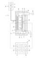
図8は、実施形態に係るプラズマ処理方法におけるHeガスのリークチェックの結果の一例を示す図である。図8(a)の縦軸は参考例に係る静電チャック113の温度を示し、図8(b)の縦軸は参考例に係るHeガスの流量を示す。横軸はいずれも時間である。図8(c)の縦軸は実施形態に係る静電チャック113の温度を示し、図8(d)の縦軸は実施形態に係るHeガスの流量を示す。横軸はいずれも時間である。Figure 8 shows an example of the results of a He gas leak check in the plasma processing method according to the embodiment. The vertical axis of Figure 8(a) shows the temperature of the
図8(a)の参考例では、静電チャック113の温度を最初(時刻0)から約250℃に制御した。図8(c)の実施形態では、静電チャックの温度を最初(時刻0)は100℃よりも低く制御し、その後約250℃に制御した。In the reference example of FIG. 8(a), the temperature of the
これによれば、図8(b)の参考例の結果では、Heガスをオン、オフした後、再びオンしたときのリーク量(流量)が多かった。これに対して、図8(d)の実施形態の結果では、Heガスをオン、オフした後、再びオンしたときのリーク量(流量)が少なかった。According to this, in the results of the reference example in FIG. 8(b), the amount of leakage (flow rate) was large when He gas was turned on, off, and then turned on again. In contrast, in the results of the embodiment in FIG. 8(d), the amount of leakage (flow rate) was small when He gas was turned on, off, and then turned on again.
以上から、第1実施形態に係るプラズマ処理方法によれば、静電チャック113の温度上昇による体積抵抗率の低下の影響を受けずに基板Wと吸着電極113aにおいて誘電分極が行われ、マイグレーションの影響を低減できる。As described above, according to the plasma processing method of the first embodiment, dielectric polarization occurs between the substrate W and the chucking
<第2実施形態>
[プラズマ処理方法]
次に、第2実施形態に係るプラズマ処理方法について、図9及び図10を参照しながら説明する。図9は、第2実施形態に係るプラズマ処理方法の一例を示すフローチャートである。図10は、第2実施形態に係るプラズマ処理方法の一例を示すタイムチャートである。なお、図9に示す処理のステップ番号が、図6に示す処理のステップ番号と同じ場合、同一処理を示す。 Second Embodiment
[Plasma treatment method]
Next, a plasma processing method according to a second embodiment will be described with reference to Fig. 9 and Fig. 10. Fig. 9 is a flow chart showing an example of the plasma processing method according to the second embodiment. Fig. 10 is a time chart showing an example of the plasma processing method according to the second embodiment. Note that when the step numbers of the processes shown in Fig. 9 are the same as the step numbers of the processes shown in Fig. 6, they indicate the same processes.
図9の方法MT2が開始されると、制御部2は、基板Wをプラズマ処理チャンバ10に搬入し、基板Wを第1温度の静電チャック113に載置する。また、制御部2は、プラズマ処理チャンバ10にArガスを供給(オン)する(ステップS1)。When method MT2 in FIG. 9 is started, the control unit 2 loads the substrate W into the
図10のタイムチャートのStepAでは、時刻t0に基板をプラズマ処理チャンバ10に搬入し、時刻t0と時刻t1の間にArガスを供給した後、時刻t1までチャンバ内を安定化させる。 In Step A of the time chart of FIG. 10, a substrate is loaded into
図9に戻り、制御部2は、ソースRF信号(HF Power)を供給(オン)し、Arガスのプラズマを生成する(ステップS21)。これによれば、Arガスのプラズマにより静電チャック113による基板Wの吸着力を確保することができる。また、HV電圧を供給する前にプラズマを生成し、そのプラズマによってHV電圧を印加する際にプラズマ処理チャンバ10内のパーティクルが基板W側へ引き込まれることを防止することができる。Returning to FIG. 9, the control unit 2 supplies (ON) a source RF signal (HF Power) to generate Ar gas plasma (step S21). This ensures that the
図9に戻り、次に、制御部2は、吸着電極113aへHV電圧の供給を開始(オン)する(ステップS3)。HV電圧は、吸着電極113aにプラスの電荷を供給してもよいし、マイナスの電荷を供給してもよい。これにより、基板Wを静電チャック113に静電吸着する。Returning to FIG. 9, next, the control unit 2 starts (turns on) the supply of HV voltage to the
図10のタイムチャートのStepBでは、時刻t1にソースRF信号を供給してHFパワーをオンし、時刻t1と時刻t2の間に第1のDC信号を供給してHV電圧をオンし、吸着電極113aにプラスの電荷を供給する。 In Step B of the time chart in FIG. 10, a source RF signal is supplied at timet1 to turn on the HF power, and a first DC signal is supplied between timet1 and timet2 to turn on the HV voltage, thereby supplying a positive charge to the
図9に戻り、次に、制御部2は、Heガスの供給を開始(オン)し、基板支持面111aと基板Wの裏面との間にHeガスを供給する。次に、制御部2は、流量モニター装置123による検出結果に基づきHeガスのリークチェックを開始する(ステップS5)。Heガスのリークチェックは、ソースRF信号を供給し、HFパワーによりArガスのプラズマが生成されている状態で、基板支持面111aと基板Wの裏面との間に供給するHeガスのリーク量(流量)を検出する。Heガスのリーク量に替えて基板支持面111aと基板Wの裏面との間の圧力を検出してもよい。Heガスがリークしている場合、流量モニター装置123が検出するHeガスの流量はHeガスがリークしていない場合よりも多くなる。よって、検出したHeガスの流量が予め設定された閾値を超えた場合、Heガスがリークしていると判定できる。Returning to FIG. 9, the control unit 2 then starts (on) the supply of He gas and supplies He gas between the
制御部2は、Heガスのリークチェックの結果、Heガスのリーク量が閾値以下であるかを判定する(ステップS7)。Heガスのリーク量が閾値よりも大きい場合、制御部2は処理を停止する。制御部2は、Heガスのリーク量が閾値以下であると判定されるときに、静電チャック113の温度を第1温度の低温から第2温度の高温に制御する。低温は、例えば100℃より低い温度である。The control unit 2 determines whether the amount of He gas leakage is equal to or less than a threshold value as a result of the He gas leak check (step S7). If the amount of He gas leakage is greater than the threshold value, the control unit 2 stops the process. When it is determined that the amount of He gas leakage is equal to or less than the threshold value, the control unit 2 controls the temperature of the
制御部2は、リーク量が閾値以下である場合、ソースRF信号の供給を停止してHFパワーをオフし(ステップS23)、静電チャック113の温度を第2温度へ上昇させる(ステップS9)。If the amount of leakage is equal to or less than the threshold, the control unit 2 stops the supply of the source RF signal and turns off the HF power (step S23), and increases the temperature of the
図10のタイムチャートのStepDでは、時刻t4でソースRF信号(HF Power)の供給を停止し、時刻t4と時刻t5の間において徐々に静電チャック113の温度を上昇させ、第2温度に制御する。第2温度は、例えば100℃以上の温度である。StepDでは、Arガスの供給を停止し、その後、プロセスガスの供給を開始する。 10 , the supply of the source RF signal (HF Power) is stopped at timet4 , and the temperature of the
図9に戻り、次に、制御部2は、プラズマ処理チャンバ10内の温度及び雰囲気を安定させる(ステップS11)。次に、制御部2は、静電チャック113が第2温度に到達してから所定の期間経過後にプラズマ処理チャンバ10内にプラズマを生成し、基板Wを処理する(ステップS13)。その後、本処理を終了する。図10のタイムチャートのStepE、Fでは、時刻t5と時刻t7の間にプラズマ処理チャンバ10内の温度及び雰囲気を安定させる。 9, the control unit 2 next stabilizes the temperature and atmosphere in the plasma processing chamber 10 (step S11). Next, the control unit 2 generates plasma in the
図10の例では、プロセスレシピに基づき、時刻t7にソースRF信号(HF Power)を供給し、時刻t7よりも少し遅れてバイアスRF信号(LF Power)を供給し、プロセスガスのプラズマを生成し、基板Wを処理する。 In the example of FIG. 10, based on the process recipe, a source RF signal (HF power) is supplied at timet7 , and a bias RF signal (LF power) is supplied slightly after timet7 to generate plasma of the process gas and process the substrate W.
以上から、第2実施形態に係るプラズマ処理方法によれば、静電チャック113の温度上昇による体積抵抗率の低下の影響を受けずに誘電分極が行われ、マイグレーションの影響を低減することができる。As described above, according to the plasma processing method of the second embodiment, dielectric polarization is performed without being affected by the decrease in volume resistivity caused by the temperature rise of the
また、基板Wを静電チャック113に吸着する工程の前にソースRF信号(HF Power)を吸着電極113aに印加し、流量又は圧力が所定の閾値を超過しているか否かを判断する工程の後にソースRF信号の印加を停止する。これにより、HV電圧を供給する前にプラズマを生成し、そのプラズマによって静電チャック113による基板Wの吸着力を確保することができる。また、HV電圧を印加する際にプラズマ処理チャンバ10内のパーティクルが基板W側へ引き込まれることを防止することができる。In addition, a source RF signal (HF Power) is applied to the
なお、第2実施形態では、図9のステップS21においてソースRF信号をオンすることで、基板Wにパーティクルが発生することを防止した。ただし、これに限らず、ステップS21においてバイアスRF信号をオンしてもよいし、ソースRF信号及びバイアスRF信号をオンしてもよい。いずれも基板Wにパーティクルが発生することを防止できる。ソースRF信号を供給した場合、基板Wの吸着力はバイアスRF信号を使用した場合よりも低いが、スパッタ効果によるダメージは生じにくい。逆に、バイアスRF信号を供給した場合、基板Wの吸着力はソースRF信号よりも高いが、スパッタ効果によるダメージが生じやすい。In the second embodiment, the source RF signal is turned on in step S21 of FIG. 9 to prevent particles from being generated on the substrate W. However, this is not limited to the above, and the bias RF signal may be turned on in step S21, or the source RF signal and the bias RF signal may be turned on. Either method can prevent particles from being generated on the substrate W. When the source RF signal is supplied, the suction force of the substrate W is lower than when the bias RF signal is used, but damage due to the sputtering effect is less likely to occur. Conversely, when the bias RF signal is supplied, the suction force of the substrate W is higher than when the source RF signal is used, but damage due to the sputtering effect is more likely to occur.
以上、本実施形態のプラズマ処理方法及びプラズマ処理装置によれば、マイグレーションの影響を受けにくい低温で基板Wを静電チャック113により静電吸着させ、誘電分極した後、静電チャック113をプロセス条件に応じた高温まで昇温する。これにより、基板Wを静電チャック113に吸着させるときの電荷の移動を抑制し、基板Wの吸着エラーの発生を防止し、その後のプロセスにおいて経時的な吸着を可能とする。As described above, according to the plasma processing method and plasma processing apparatus of this embodiment, the substrate W is electrostatically attracted by the
今回開示された実施形態に係るプラズマ処理方法及びプラズマ処理装置は、すべての点において例示であって制限的なものではないと考えられるべきである。実施形態は、添付の請求の範囲及びその主旨を逸脱することなく、様々な形態で変形及び改良が可能である。上記複数の実施形態に記載された事項は、矛盾しない範囲で他の構成も取り得ることができ、また、矛盾しない範囲で組み合わせることができる。The plasma processing method and plasma processing apparatus according to the embodiments disclosed herein should be considered in all respects as illustrative and not restrictive. The embodiments can be modified and improved in various ways without departing from the scope and spirit of the appended claims. The matters described in the above embodiments can be configured in other ways as long as they are not inconsistent, and can be combined as long as they are not inconsistent.
本開示のプラズマ処理装置は、Atomic Layer Deposition(ALD)装置、Capacitively Coupled Plasma(CCP)、Inductively Coupled Plasma(ICP)、Radial Line Slot Antenna(RLSA)、Electron Cyclotron Resonance Plasma(ECR)、Helicon Wave Plasma(HWP)のいずれのタイプの装置でも適用可能である。The plasma processing apparatus disclosed herein can be applied to any type of apparatus, including Atomic Layer Deposition (ALD) apparatus, Capacitively Coupled Plasma (CCP), Inductively Coupled Plasma (ICP), Radial Line Slot Antenna (RLSA), Electron Cyclotron Resonance Plasma (ECR), and Helicon Wave Plasma (HWP).
1 プラズマ処理装置
2 制御部
2a コンピュータ
2a1 処理部
2a2 記憶部
2a3 通信インターフェース
10 プラズマ処理チャンバ
11 基板支持部
13 シャワーヘッド
21 ガスソース
20 ガス供給部
30 電源
31 RF電源
31a 第1のRF生成部
31b 第2のRF生成部
32a 第1のDC生成部
32b 第2のDC生成部
40 排気システム
111 本体部
112 リングアセンブリREFERENCE SIGNS LIST 1 Plasma processing apparatus 2
Claims (20)
Translated fromJapanese(b)前記プラズマ処理チャンバ内に配置された第1温度の静電チャックに基板を載置する工程と、
(c)前記基板を前記静電チャックに静電吸着する工程と、
(d)前記基板と前記静電チャックの間に伝熱ガスの供給を開始する工程と、
(e)前記伝熱ガスの流量又は前記基板と前記静電チャックの間の圧力を検出する工程と、
(f)前記流量又は前記圧力が所定の閾値を超過しているか否かを判定する工程と、
(g)前記判定の結果に基づき、前記不活性ガスの供給を停止した後に前記静電チャックを前記第1温度より高い第2温度に昇温させる工程と、
(h)前記プラズマ処理チャンバ内にプロセスガスによりプラズマを生成する工程と、
を有する、プラズマ処理方法。(a) providing an inert gas into a plasma processing chamber;
(b) placing a substrate on an electrostatic chuck at a first temperature disposed within the plasma processing chamber;
(c) electrostatically attracting the substrate to the electrostatic chuck;
(d) initiating a supply of a heat transfer gas between the substrate and the electrostatic chuck;
(e) detecting a flow rate of the heat transfer gas or a pressure between the substrate and the electrostatic chuck;
(f) determining whether the flow rate or the pressure exceeds a predetermined threshold;
(g) increasing the temperature of the electrostatic chuck to a second temperature higher than the first temperatureafter stopping the supply of the inert gas based on a result of the determination;
(h) generating a plasmawith a process gas in the plasma processing chamber;
The plasma processing method comprises:
請求項1に記載のプラズマ処理方法。Thestep (g) includes continuously increasing the temperature to a second temperature higher than the first temperature.
The plasma processing method according to claim 1 .
請求項1に記載のプラズマ処理方法。Thestep (g) includes gradually increasing the temperature to a second temperature higher than the first temperature.
The plasma processing method according to claim 1 .
請求項1~3のいずれか一項に記載のプラズマ処理方法。 generating a plasma in the plasma processing chamber a predetermined time after the electrostatic chuck reaches the second temperature;
The plasma processing method according to any one of claims 1 to 3.
前記流量又は前記圧力が所定の閾値を超過しているか否かを判断する工程の後に前記高周波電力の印加を停止する、
請求項1~4のいずれか一項に記載のプラズマ処理方法。 applying radio frequency power to an electrode disposed within the plasma processing chamber prior to the step of attracting the substrate to the electrostatic chuck;
Stopping the application of the high frequency power after the step of determining whether the flow rate or the pressure exceeds a predetermined threshold value.
The plasma processing method according to any one of claims 1 to 4.
請求項5に記載のプラズマ処理方法。 The high frequency power is at least one of a source RF signal for plasma generation and a bias RF signal having a frequency lower than that of the source RF signal.
The plasma processing method according to claim 5 .
請求項1~6のいずれか一項に記載のプラズマ処理方法。(i) after the step(g) and before the step(h) , a step of stabilizing an atmosphere in the plasma processing chamber;
The plasma processing method according to any one of claims 1 to 6.
請求項1~7のいずれか一項に記載のプラズマ処理方法。 The step(e) includes detecting the flow rateor the pressure when the heat transfer gas is suppliedagain after the supply of the heat transfer gas between the substrate and the electrostatic chuck is stopped after a predetermined time has elapsed since the supply of the heat transfer gas between the substrate and the electrostatic chuck was started in the step (d).
The plasma processing method according to any one of claims 1 to 7.
請求項1~8のいずれか一項に記載のプラズマ処理方法。 The step(g) includes increasing the temperature of the electrostatic chuck when the flow rate or the pressure is equal to or lower than a predetermined threshold value.
The plasma processing method according to any one of claims 1 to 8.
請求項9に記載のプラズマ処理方法。 The step(g) includes not increasing the temperature of the electrostatic chuck while the flow rate or the pressure exceeds a predetermined threshold.
The plasma processing method according to claim 9 .
制御部と、を有するプラズマ処理装置であって、
前記制御部は、
(a)前記プラズマ処理チャンバ内に不活性ガスを供給する工程と、
(b)前記プラズマ処理チャンバ内に配置された第1温度の静電チャックに基板を載置する工程と、
(c)前記基板を前記静電チャックに静電吸着する工程と、
(d)前記基板と前記静電チャックの間に伝熱ガスの供給を開始する工程と、
(e)前記伝熱ガスの流量又は前記基板と前記静電チャックの間の圧力を検出する工程と、
(f)前記流量又は前記圧力が所定の閾値を超過しているか否かを判定する工程と、
(g)前記判定の結果に基づき、前記不活性ガスの供給を停止した後に前記静電チャックを前記第1温度より高い第2温度に昇温させる工程と、
(h)前記プラズマ処理チャンバ内にプロセスガスによりプラズマを生成する工程と、
を含む工程を制御する、プラズマ処理装置。 a plasma processing chamber; and an electrostatic chuck disposed within the plasma processing chamber;
A plasma processing apparatus having a control unit,
The control unit is
(a) providing an inert gas into the plasma processing chamber;
(b) placing a substrate on an electrostatic chuck at a first temperature disposed within the plasma processing chamber;
(c) electrostatically attracting the substrate to the electrostatic chuck;
(d) initiating a supply of a heat transfer gas between the substrate and the electrostatic chuck;
(e) detecting a flow rate of the heat transfer gas or a pressure between the substrate and the electrostatic chuck;
(f) determining whether the flow rate or the pressure exceeds a predetermined threshold;
(g) increasing the temperature of the electrostatic chuck to a second temperature higher than the first temperatureafter stopping the supply of the inert gas based on a result of the determination;
(h) generating a plasmawith a process gas in the plasma processing chamber;
The plasma processing apparatus controls a process including the steps of:
請求項11に記載のプラズマ処理装置。The plasma processing apparatus according to claim 11 .
請求項11に記載のプラズマ処理装置。The plasma processing apparatus according to claim 11 .
請求項11~13のいずれか一項に記載のプラズマ処理装置。The plasma processing apparatus according to any one of claims 11 to 13.
前記流量又は前記圧力が所定の閾値を超過しているか否かを判断する工程の後に前記高周波電力の印加を停止する、Stopping the application of the high frequency power after the step of determining whether the flow rate or the pressure exceeds a predetermined threshold value.
請求項11~14のいずれか一項に記載のプラズマ処理装置。The plasma processing apparatus according to any one of claims 11 to 14.
請求項15に記載のプラズマ処理装置。The plasma processing apparatus according to claim 15 .
請求項11~16のいずれか一項に記載のプラズマ処理装置。The plasma processing apparatus according to any one of claims 11 to 16.
請求項11~17のいずれか一項に記載のプラズマ処理装置。The plasma processing apparatus according to any one of claims 11 to 17.
請求項11~18のいずれか一項に記載のプラズマ処理装置。The plasma processing apparatus according to any one of claims 11 to 18.
請求項19に記載のプラズマ処理装置。The plasma processing apparatus according to claim 19.
Priority Applications (5)
| Application Number | Priority Date | Filing Date | Title |
|---|---|---|---|
| JP2021147135AJP7652489B2 (en) | 2021-09-09 | 2021-09-09 | Plasma processing method and plasma processing apparatus |
| TW111132595ATW202331917A (en) | 2021-09-09 | 2022-08-30 | Plasma processing method and plasma processing apparatus |
| US17/823,598US12142465B2 (en) | 2021-09-09 | 2022-08-31 | Plasma processing method and plasma processing apparatus |
| CN202211072742.6ACN115799029A (en) | 2021-09-09 | 2022-09-02 | Plasma processing method and plasma processing apparatus |
| KR1020220111318AKR20230037452A (en) | 2021-09-09 | 2022-09-02 | Plasma processing method and plasma processing apparatus |
Applications Claiming Priority (1)
| Application Number | Priority Date | Filing Date | Title |
|---|---|---|---|
| JP2021147135AJP7652489B2 (en) | 2021-09-09 | 2021-09-09 | Plasma processing method and plasma processing apparatus |
Publications (2)
| Publication Number | Publication Date |
|---|---|
| JP2023039828A JP2023039828A (en) | 2023-03-22 |
| JP7652489B2true JP7652489B2 (en) | 2025-03-27 |
Family
ID=85385552
Family Applications (1)
| Application Number | Title | Priority Date | Filing Date |
|---|---|---|---|
| JP2021147135AActiveJP7652489B2 (en) | 2021-09-09 | 2021-09-09 | Plasma processing method and plasma processing apparatus |
Country Status (5)
| Country | Link |
|---|---|
| US (1) | US12142465B2 (en) |
| JP (1) | JP7652489B2 (en) |
| KR (1) | KR20230037452A (en) |
| CN (1) | CN115799029A (en) |
| TW (1) | TW202331917A (en) |
Families Citing this family (1)
| Publication number | Priority date | Publication date | Assignee | Title |
|---|---|---|---|---|
| DE202021100710U1 (en)* | 2021-02-12 | 2021-02-19 | TRUMPF Hüttinger GmbH + Co. KG | Power supply device and plasma system |
Citations (10)
| Publication number | Priority date | Publication date | Assignee | Title |
|---|---|---|---|---|
| JP2001110885A (en) | 1999-10-14 | 2001-04-20 | Hitachi Ltd | Semiconductor processing apparatus and semiconductor processing method |
| JP2002246453A (en) | 2001-02-15 | 2002-08-30 | Anelva Corp | Method of detecting adhesion of particles to electrostatic suction stage, method of determining necessity of cleaning of electrostatic suction stage, and substrate processing apparatus |
| JP2005136350A (en) | 2003-10-31 | 2005-05-26 | Tokyo Electron Ltd | Electrostatic chuck, plasma processing apparatus, and plasma processing method |
| JP2014011215A (en) | 2012-06-28 | 2014-01-20 | Hitachi High-Technologies Corp | Plasma treatment apparatus and plasma treatment method |
| JP2015041669A (en) | 2013-08-21 | 2015-03-02 | 住友電気工業株式会社 | Manufacturing method of semiconductor device |
| JP2015124398A (en) | 2013-12-25 | 2015-07-06 | 東京エレクトロン株式会社 | Method for forming Ti film |
| JP2019091756A (en) | 2017-11-13 | 2019-06-13 | サムコ株式会社 | Stage and plasma processing device |
| JP2019519098A (en) | 2016-05-05 | 2019-07-04 | アプライド マテリアルズ インコーポレイテッドApplied Materials,Incorporated | Advanced temperature control for wafer carrier in plasma processing chamber |
| JP2019211523A (en) | 2018-05-31 | 2019-12-12 | キヤノン株式会社 | Method for manufacturing electrophotographic photoreceptor |
| US20200357675A1 (en) | 2019-05-06 | 2020-11-12 | Applied Materials, Inc. | Methods and apparatus for dechucking wafers |
Family Cites Families (4)
| Publication number | Priority date | Publication date | Assignee | Title |
|---|---|---|---|---|
| JPH07231032A (en)* | 1994-02-15 | 1995-08-29 | Oki Electric Ind Co Ltd | Sample holder |
| US6125025A (en)* | 1998-09-30 | 2000-09-26 | Lam Research Corporation | Electrostatic dechucking method and apparatus for dielectric workpieces in vacuum processors |
| JP2003197609A (en)* | 2001-12-27 | 2003-07-11 | Tokyo Electron Ltd | Method for monitoring plasma treatment device, and plasma treatment device |
| JP6861579B2 (en) | 2017-06-02 | 2021-04-21 | 東京エレクトロン株式会社 | Plasma processing equipment, electrostatic adsorption method and electrostatic adsorption program |
- 2021
- 2021-09-09JPJP2021147135Apatent/JP7652489B2/enactiveActive
- 2022
- 2022-08-30TWTW111132595Apatent/TW202331917A/enunknown
- 2022-08-31USUS17/823,598patent/US12142465B2/enactiveActive
- 2022-09-02CNCN202211072742.6Apatent/CN115799029A/enactivePending
- 2022-09-02KRKR1020220111318Apatent/KR20230037452A/enactivePending
Patent Citations (10)
| Publication number | Priority date | Publication date | Assignee | Title |
|---|---|---|---|---|
| JP2001110885A (en) | 1999-10-14 | 2001-04-20 | Hitachi Ltd | Semiconductor processing apparatus and semiconductor processing method |
| JP2002246453A (en) | 2001-02-15 | 2002-08-30 | Anelva Corp | Method of detecting adhesion of particles to electrostatic suction stage, method of determining necessity of cleaning of electrostatic suction stage, and substrate processing apparatus |
| JP2005136350A (en) | 2003-10-31 | 2005-05-26 | Tokyo Electron Ltd | Electrostatic chuck, plasma processing apparatus, and plasma processing method |
| JP2014011215A (en) | 2012-06-28 | 2014-01-20 | Hitachi High-Technologies Corp | Plasma treatment apparatus and plasma treatment method |
| JP2015041669A (en) | 2013-08-21 | 2015-03-02 | 住友電気工業株式会社 | Manufacturing method of semiconductor device |
| JP2015124398A (en) | 2013-12-25 | 2015-07-06 | 東京エレクトロン株式会社 | Method for forming Ti film |
| JP2019519098A (en) | 2016-05-05 | 2019-07-04 | アプライド マテリアルズ インコーポレイテッドApplied Materials,Incorporated | Advanced temperature control for wafer carrier in plasma processing chamber |
| JP2019091756A (en) | 2017-11-13 | 2019-06-13 | サムコ株式会社 | Stage and plasma processing device |
| JP2019211523A (en) | 2018-05-31 | 2019-12-12 | キヤノン株式会社 | Method for manufacturing electrophotographic photoreceptor |
| US20200357675A1 (en) | 2019-05-06 | 2020-11-12 | Applied Materials, Inc. | Methods and apparatus for dechucking wafers |
Also Published As
| Publication number | Publication date |
|---|---|
| US12142465B2 (en) | 2024-11-12 |
| KR20230037452A (en) | 2023-03-16 |
| US20230072102A1 (en) | 2023-03-09 |
| JP2023039828A (en) | 2023-03-22 |
| TW202331917A (en) | 2023-08-01 |
| CN115799029A (en) | 2023-03-14 |
Similar Documents
| Publication | Publication Date | Title |
|---|---|---|
| US8440050B2 (en) | Plasma processing apparatus and method, and storage medium | |
| US11764038B2 (en) | Plasma processing apparatus, electrostatic attraction method, and electrostatic attraction program | |
| US9275836B2 (en) | Plasma processing apparatus and plasma processing method | |
| US9852922B2 (en) | Plasma processing method | |
| US11538668B2 (en) | Mounting stage, substrate processing device, and edge ring | |
| JP7433164B2 (en) | Substrate processing system | |
| US20060037704A1 (en) | Plasma Processing apparatus and method | |
| US20170338084A1 (en) | Plasma processing method | |
| US12125672B2 (en) | Plasma processing method and plasma processing apparatus | |
| JP7652489B2 (en) | Plasma processing method and plasma processing apparatus | |
| US20240258078A1 (en) | Plasma processing apparatus, electrostatic chuck, and plasma processing method | |
| KR102758199B1 (en) | Plasma processing apparatus and plasma processing method | |
| JP7561647B2 (en) | Plasma processing apparatus and plasma processing method | |
| JP7621308B2 (en) | Plasma processing apparatus and plasma processing method | |
| US12362145B2 (en) | Plasma processing apparatus and plasma processing method | |
| US20240387143A1 (en) | Plasma processing apparatus, power source system, and plasma processing method | |
| JP2024135093A (en) | Plasma Processing Equipment | |
| JP2024092751A (en) | Substrate holding method and substrate processing system | |
| JP2022143200A (en) | Plasma processing device and method of controlling plasma processing device | |
| JP2025024972A (en) | Substrate processing method and substrate processing apparatus | |
| WO2025216074A1 (en) | Substrate processing method and substrate processing apparatus | |
| WO2024171821A1 (en) | Plasma treatment device and plasma treatment method |
Legal Events
| Date | Code | Title | Description |
|---|---|---|---|
| A621 | Written request for application examination | Free format text:JAPANESE INTERMEDIATE CODE: A621 Effective date:20240312 | |
| A977 | Report on retrieval | Free format text:JAPANESE INTERMEDIATE CODE: A971007 Effective date:20241113 | |
| A131 | Notification of reasons for refusal | Free format text:JAPANESE INTERMEDIATE CODE: A131 Effective date:20241126 | |
| A521 | Request for written amendment filed | Free format text:JAPANESE INTERMEDIATE CODE: A523 Effective date:20250127 | |
| TRDD | Decision of grant or rejection written | ||
| A01 | Written decision to grant a patent or to grant a registration (utility model) | Free format text:JAPANESE INTERMEDIATE CODE: A01 Effective date:20250212 | |
| A61 | First payment of annual fees (during grant procedure) | Free format text:JAPANESE INTERMEDIATE CODE: A61 Effective date:20250311 | |
| R150 | Certificate of patent or registration of utility model | Ref document number:7652489 Country of ref document:JP Free format text:JAPANESE INTERMEDIATE CODE: R150 |