JP7652282B2 - Notification device, notification device control program, and seat system - Google Patents
Notification device, notification device control program, and seat systemDownload PDFInfo
- Publication number
- JP7652282B2 JP7652282B2JP2023556245AJP2023556245AJP7652282B2JP 7652282 B2JP7652282 B2JP 7652282B2JP 2023556245 AJP2023556245 AJP 2023556245AJP 2023556245 AJP2023556245 AJP 2023556245AJP 7652282 B2JP7652282 B2JP 7652282B2
- Authority
- JP
- Japan
- Prior art keywords
- frequency
- vibration
- drive
- actuator
- signal
- Prior art date
- Legal status (The legal status is an assumption and is not a legal conclusion. Google has not performed a legal analysis and makes no representation as to the accuracy of the status listed.)
- Active
Links
Images


Classifications
- G—PHYSICS
- G10—MUSICAL INSTRUMENTS; ACOUSTICS
- G10K—SOUND-PRODUCING DEVICES; METHODS OR DEVICES FOR PROTECTING AGAINST, OR FOR DAMPING, NOISE OR OTHER ACOUSTIC WAVES IN GENERAL; ACOUSTICS NOT OTHERWISE PROVIDED FOR
- G10K11/00—Methods or devices for transmitting, conducting or directing sound in general; Methods or devices for protecting against, or for damping, noise or other acoustic waves in general
- G10K11/16—Methods or devices for protecting against, or for damping, noise or other acoustic waves in general
- G10K11/175—Methods or devices for protecting against, or for damping, noise or other acoustic waves in general using interference effects; Masking sound
- G10K11/178—Methods or devices for protecting against, or for damping, noise or other acoustic waves in general using interference effects; Masking sound by electro-acoustically regenerating the original acoustic waves in anti-phase
- A—HUMAN NECESSITIES
- A47—FURNITURE; DOMESTIC ARTICLES OR APPLIANCES; COFFEE MILLS; SPICE MILLS; SUCTION CLEANERS IN GENERAL
- A47C—CHAIRS; SOFAS; BEDS
- A47C7/00—Parts, details, or accessories of chairs or stools
- A47C7/62—Accessories for chairs
- B—PERFORMING OPERATIONS; TRANSPORTING
- B06—GENERATING OR TRANSMITTING MECHANICAL VIBRATIONS IN GENERAL
- B06B—METHODS OR APPARATUS FOR GENERATING OR TRANSMITTING MECHANICAL VIBRATIONS OF INFRASONIC, SONIC, OR ULTRASONIC FREQUENCY, e.g. FOR PERFORMING MECHANICAL WORK IN GENERAL
- B06B1/00—Methods or apparatus for generating mechanical vibrations of infrasonic, sonic, or ultrasonic frequency
- B06B1/02—Methods or apparatus for generating mechanical vibrations of infrasonic, sonic, or ultrasonic frequency making use of electrical energy
- B06B1/04—Methods or apparatus for generating mechanical vibrations of infrasonic, sonic, or ultrasonic frequency making use of electrical energy operating with electromagnetism
- B—PERFORMING OPERATIONS; TRANSPORTING
- B06—GENERATING OR TRANSMITTING MECHANICAL VIBRATIONS IN GENERAL
- B06B—METHODS OR APPARATUS FOR GENERATING OR TRANSMITTING MECHANICAL VIBRATIONS OF INFRASONIC, SONIC, OR ULTRASONIC FREQUENCY, e.g. FOR PERFORMING MECHANICAL WORK IN GENERAL
- B06B1/00—Methods or apparatus for generating mechanical vibrations of infrasonic, sonic, or ultrasonic frequency
- B06B1/02—Methods or apparatus for generating mechanical vibrations of infrasonic, sonic, or ultrasonic frequency making use of electrical energy
- B06B1/06—Methods or apparatus for generating mechanical vibrations of infrasonic, sonic, or ultrasonic frequency making use of electrical energy operating with piezoelectric effect or with electrostriction
- B—PERFORMING OPERATIONS; TRANSPORTING
- B60—VEHICLES IN GENERAL
- B60N—SEATS SPECIALLY ADAPTED FOR VEHICLES; VEHICLE PASSENGER ACCOMMODATION NOT OTHERWISE PROVIDED FOR
- B60N2/00—Seats specially adapted for vehicles; Arrangement or mounting of seats in vehicles
- B60N2/90—Details or parts not otherwise provided for
- G—PHYSICS
- G06—COMPUTING OR CALCULATING; COUNTING
- G06F—ELECTRIC DIGITAL DATA PROCESSING
- G06F3/00—Input arrangements for transferring data to be processed into a form capable of being handled by the computer; Output arrangements for transferring data from processing unit to output unit, e.g. interface arrangements
- G06F3/01—Input arrangements or combined input and output arrangements for interaction between user and computer
- G—PHYSICS
- G08—SIGNALLING
- G08B—SIGNALLING OR CALLING SYSTEMS; ORDER TELEGRAPHS; ALARM SYSTEMS
- G08B6/00—Tactile signalling systems, e.g. personal calling systems
- H—ELECTRICITY
- H04—ELECTRIC COMMUNICATION TECHNIQUE
- H04R—LOUDSPEAKERS, MICROPHONES, GRAMOPHONE PICK-UPS OR LIKE ACOUSTIC ELECTROMECHANICAL TRANSDUCERS; DEAF-AID SETS; PUBLIC ADDRESS SYSTEMS
- H04R1/00—Details of transducers, loudspeakers or microphones
- H—ELECTRICITY
- H04—ELECTRIC COMMUNICATION TECHNIQUE
- H04R—LOUDSPEAKERS, MICROPHONES, GRAMOPHONE PICK-UPS OR LIKE ACOUSTIC ELECTROMECHANICAL TRANSDUCERS; DEAF-AID SETS; PUBLIC ADDRESS SYSTEMS
- H04R1/00—Details of transducers, loudspeakers or microphones
- H04R1/02—Casings; Cabinets ; Supports therefor; Mountings therein
Landscapes
- Engineering & Computer Science (AREA)
- Physics & Mathematics (AREA)
- Acoustics & Sound (AREA)
- Mechanical Engineering (AREA)
- General Physics & Mathematics (AREA)
- Multimedia (AREA)
- General Engineering & Computer Science (AREA)
- Theoretical Computer Science (AREA)
- Signal Processing (AREA)
- Electromagnetism (AREA)
- Aviation & Aerospace Engineering (AREA)
- Transportation (AREA)
- Human Computer Interaction (AREA)
- Seats For Vehicles (AREA)
Description
Translated fromJapanese本開示は、報知装置、報知装置の制御プログラム、及びシートシステムに関する。The present disclosure relates to an alarm device, a control program for the alarm device, and a seat system.
従来より、車両のシート等に設けられた振動子(アクチュエータ)を振動させることで、運転者にその振動を感知させて、情報を提示する装置が知られている。このような装置では、危険な状況を振動警報として運転者に提示したり、ナビ情報を基に、右左折の折に振動を運転者に提示して、目的地までの誘導を行うこと等が知られている(例えば、特許文献1参照)。Conventionally, there are known devices that vibrate a vibrator (actuator) installed in a vehicle seat or the like, allowing the driver to sense the vibration and provide information to the driver. Such devices are known to notify the driver of dangerous situations as a vibration warning, or to guide the driver to the destination by providing vibrations to the driver when making right or left turns based on navigation information (see, for example, Patent Document 1).
ところで、特許文献1に記載の装置では、アクチュエータを振動させる駆動周波数によっては、シートや装置自体の共振周波数との関係で、シートや装置自体から音が発生する場合がある。このような音の発生は、好ましくない場合がある。However, in the device described in Patent Document 1, depending on the drive frequency that vibrates the actuator, sound may be generated from the seat or the device itself due to its resonance frequency. Such sound generation may be undesirable.
そこで、本開示は、アクチュエータの振動によって生じる音を低減することが可能な報知装置、報知装置の制御プログラム、及びシートシステムを提供することを目的とする。Therefore, the present disclosure aims to provide an alarm device, a control program for the alarm device, and a seat system that are capable of reducing the sound generated by the vibration of the actuator.
本開示の実施形態の報知装置は、対象物に取り付けられ、振動による触覚の呈示により前記対象物を利用する利用者に報知を行う報知装置であって、イベントの種類に応じた駆動周波数の信号パターンを有する駆動信号を出力する信号出力部と、前記駆動信号によって駆動されるアクチュエータと、音波を出力する音出力部と、前記アクチュエータの振動に伴って生じる音波を打ち消す打消音波を前記音出力部から出力させるかどうかを、前記駆動信号の駆動周波数に基づいて決定する制御部とを含む。An alarm device according to an embodiment of the present disclosure is attached to an object and alerts a user who uses the object by providing a tactile sensation through vibration, and includes a signal output unit that outputs a drive signal having a signal pattern with a drive frequency according to the type of event, an actuator driven by the drive signal, a sound output unit that outputs sound waves, and a control unit that determines, based on the drive frequency of the drive signal, whether to cause the sound output unit to output canceling sound waves that cancel out the sound waves generated by the vibration of the actuator.
本開示の実施形態の報知装置の制御プログラムは、対象物に取り付けられ、振動による触覚の呈示により前記対象物を利用する利用者に報知を行う報知装置であって、振動を発生するアクチュエータと、音波を出力する音出力部とを含む報知装置を制御する報知装置の制御プログラムであって、前記報知装置のコンピュータが、イベントの種類に応じた駆動周波数の信号パターンを有する駆動信号を前記アクチュエータに出力して前記アクチュエータを振動させ、前記アクチュエータの振動に伴って生じる音波を打ち消す打消音波を前記音出力部から出力させるかどうかを、前記駆動信号の駆動周波数に基づいて決定する。The control program for an alarm device of an embodiment of the present disclosure is an alarm device that is attached to an object and alerts a user who uses the object by presenting a tactile sensation through vibration, and is a control program for an alarm device that controls an alarm device that includes an actuator that generates vibrations and a sound output unit that outputs sound waves, and a computer of the alarm device outputs a drive signal having a signal pattern with a drive frequency that corresponds to the type of event to the actuator to vibrate the actuator, and determines, based on the drive frequency of the drive signal, whether to cause the sound output unit to output canceling sound waves that cancel out the sound waves generated by the vibration of the actuator.
本開示の実施形態のシートシステムは、シートと、振動による触覚の呈示により利用者に報知を行う報知装置とを含むシートシステムであって、前記報知装置は、イベントの種類に応じた駆動周波数の信号パターンを有する駆動信号を出力する信号出力部と、前記駆動信号によって駆動されるアクチュエータと、音波を出力する音出力部と、前記アクチュエータの振動に伴って生じる音波を打ち消す打消音波を前記音出力部から出力させるかどうかを、前記駆動信号の駆動周波数に基づいて決定する制御部とを有する。A seat system according to an embodiment of the present disclosure is a seat system including a seat and an alarm device that alerts a user by presenting a tactile sensation through vibration, the alarm device having a signal output unit that outputs a drive signal having a signal pattern with a drive frequency corresponding to a type of event, an actuator driven by the drive signal, a sound output unit that outputs sound waves, and a control unit that determines, based on the drive frequency of the drive signal, whether to cause the sound output unit to output cancelling sound waves that cancel out the sound waves generated by the vibration of the actuator.
本開示によれば、アクチュエータの振動によって生じる音を低減することが可能な報知装置、報知装置の制御プログラム、及びシートシステムを提供することができる。The present disclosure provides an alarm device, a control program for the alarm device, and a seat system that can reduce noise caused by vibration of an actuator.
以下、本開示の報知装置、報知装置の制御プログラム、及びシートシステムを適用した実施形態について説明する。以下において、音波とは人間の可聴周波数の伝搬波であり、音とは人間の耳の聴覚が知覚する音波の圧力変動であるが、どちらでも表現可能な場合があるため、以下では両者を厳密に区別せずに説明する場合がある。Below, an embodiment in which the disclosed notification device, notification device control program, and seat system are applied will be described. In the following, sound waves are propagating waves of human audible frequencies, and sound is the pressure fluctuation of sound waves perceived by the hearing of the human ear, but since either term can be used in some cases, the following description may not strictly distinguish between the two.
<実施形態>
図1は、車両10の内部を示す図である。車両10の室内にはシート11が配置されている。シート11は、背もたれ部(シートバック)11A、座部(シートクッション)11B、ヘッドレスト11C、及びシート生地11Dを有する。背もたれ部11A、座部11B、及びヘッドレスト11Cは、シート生地11Dに覆われている。 <Embodiment>
1 is a diagram showing the interior of a
本実施形態では、後述する報知装置100が取り付けられる対象物(以下、単に「対象物」とも記載する。)の一例がシート11であり、シート11が運転席のシートである例を用いて説明する。このため、以下ではシート11の利用者は運転者である。しかしながら、シート11は、車両10に設けられるシートであればよく、例えば助手席のシートであってもよいし、後部座席のシートであってもよい。また、シート11は、車両10以外の物に設けられていてもよい。また、対象物の一例は、シート11に限られず、利用者の身体の少なくとも一部に接触した状態で利用され、報知装置100によって発生される対象物の振動が身体の少なくとも一部に伝達されるものであればよい。例えば、対象物は、ウェアラブルなデバイス(例えば、リストバンドタイプ、ベルトタイプ、着用スーツタイプ等)であってもよく、聴覚障害や視覚障害を有する者を支援するデバイスであってもよく、作業支援用のパワーアシストスーツのようなデバイスであってもよい。以下では、対象物がシート11である例について説明するが、シート11から発生する音に関する説明等、シート11について説明した事項は、対象物がシート11以外である場合についても同様に成立する。In this embodiment, an example of an object (hereinafter, also simply referred to as "object") to which the
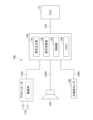
車両10には、本実施形態のシートシステム200が搭載されている。シートシステム200は、シート11及び報知装置100を含む。報知装置100は、アクチュエータ110、スピーカ120、加速度センサ130、及び制御装置140を含む。図1では、アクチュエータ110を破線で示し、スピーカ120を一点鎖線で示す。スピーカ120は、音出力部の一例である。The
報知装置100は、シート11に設けられるアクチュエータ110を駆動して振動させることによって、シート11に着座する利用者に情報を報知する装置である。情報の報知は、利用者への振動の呈示によって行われる。一般的に利用者により確実に振動を呈示するには、振動の加速度を大きくすればよい。しかしながら、振動の加速度を大きくすると音が発生しやすくなるというトレードオフが生じる。報知装置100は、振動によって発生する音が利用者に聞こえやすい状態である場合に、スピーカ120から打消音波を発生させて、振動による音を打ち消す。The
一例として、背もたれ部11Aには4個のアクチュエータ110と、2個のスピーカ120と、1個の加速度センサ130とが内蔵されており、座部11Bには4個のアクチュエータ110が内蔵されている。ヘッドレスト11Cには2個のスピーカ120が内蔵されている。すべてのアクチュエータ110、スピーカ120、及び加速度センサ130は、シート生地11Dに覆われている。また、制御装置140は、一例としてダッシュボードの裏側に配置されている。以下では、図1に加えて図2を用いて説明する。As an example, the
図2は、報知装置100の構成を示す図である。図2では簡略化してアクチュエータ110及びスピーカ120を1つずつ示すが、実際には図1に示すように複数のアクチュエータ110及びスピーカ120が制御装置140に接続されている。Figure 2 is a diagram showing the configuration of the
また、図2には、報知装置100に加えてECU(Electronic Control Unit)12を示す。ECU12は、一例として車両10のナビゲーションシステムの制御を行うECUである。なお、ここではECU12がナビゲーションシステムの制御を行うECUである形態について説明するが、ECU12はナビゲーションシステムの制御を行うECU以外のECUであってもよい。また、制御装置140はECU12に含まれていてもよい。2 also shows an ECU (Electronic Control Unit) 12 in addition to the
アクチュエータ110、スピーカ120、及び加速度センサ130は、通信ケーブル110A、120A、130Aを介して制御装置140にそれぞれ接続されており、制御装置140は通信ケーブル12Aを介してECU12に接続されている。アクチュエータ110及びスピーカ120の駆動制御は制御装置140によって行われる。制御装置140はアクチュエータ110及びスピーカ120の駆動制御を行う際に加速度センサ130の検出結果を用いる場合がある。The
通信ケーブル110A、120A、130A、及び12Aは、一例としてCAN(Controller Area Network)等の規格の通信ケーブルである。なお、アクチュエータ110、スピーカ120、加速度センサ130、及びECU12と、制御装置140との間の通信は、通信ケーブル110A、120A、130A、及び12Aによる有線通信には限定されず、それらの一部又は全てが無線通信であってもよい。The
<アクチュエータ110の構成及び動作>
アクチュエータ110は、図1に示すように、背もたれ部11A及び座部11Bに、それぞれ4個ずつ、2×2の配置で設けられる。アクチュエータ110は、制御装置140の信号出力部141(図2参照)から出力される駆動信号によって駆動され、振動を発生する。アクチュエータ110を駆動することによって対象物としてのシート11が振動する。 <Configuration and Operation of Actuator 110>
As shown in Fig. 1, four
アクチュエータ110は、図2に示すように振動体111と筐体112とを有してもよい。振動体111は、筐体112に覆われている。アクチュエータ110に駆動信号が供給されると、アクチュエータ110は、入力された駆動信号に基づいて、振動体111を振動させる。振動体111が振動すると、筐体112も振動する。アクチュエータ110の振動はシート11に伝わる。2, the
アクチュエータ110は、駆動信号によって駆動されることで筐体112に対して振動体111を振動させるものであればどのようなアクチュエータであってもよい。アクチュエータ110は、例えば、ボイスコイルモータ(VCM)、リニアアクチュエータ(共振タイプ・非共振タイプのいずれでもよい)、振動体としてのピエゾ素子を備えたピエゾアクチュエータ等であってもよい。筐体112は、振動体111を覆うケースであればどのような筐体であってもよいが、一例として樹脂製の箱型のケースである。アクチュエータ110は、筐体112がシート11に取り付けられることによって、シート11に固定されている。The
ところで、振動体111を振動させると、筐体112から音が生じる場合があり、また、シート11から音が生じる場合がある。筐体112が発生する音は、特にアクチュエータ110がQ値(Quality factor、品質係数)の高い共振周波数特性を有するような場合に大きくなる。また、シート11から生じる音は、シート11で固有振動が発生する場合に大きくなる。このように、アクチュエータ110の筐体112が発生する音や、シート11から生じる音は、アクチュエータ110の振動に伴って生じる音であり、アクチュエータ110の振動に伴って生じる音波の一例である。By the way, when the vibrating body 111 is vibrated, sound may be generated from the
以下では、アクチュエータ110の振動に伴って生じる音(アクチュエータ110の振動に伴って生じる音波の一例)を振動音波と称す。振動音波は、アクチュエータ110の筐体112が発生する音と、シート11が発生する音との少なくとも一方を含み、両方を含んでもよい。Hereinafter, the sound generated by the vibration of the actuator 110 (one example of a sound wave generated by the vibration of the actuator 110) will be referred to as a vibration sound wave. The vibration sound wave includes at least one of the sound generated by the
<スピーカ120の構成及び動作>
スピーカ120は、音波を出力する音出力部の一例である。スピーカ120は、制御装置140の制御部143によって駆動される。制御部143が打消信号をスピーカ120に供給すると、スピーカ120は打消音波を出力する。制御装置140の信号出力部141からアクチュエータ110に出力される駆動信号は、オン期間とオフ期間が繰り返される駆動信号である。打消音波は少なくともオン期間において振動音波を打ち消すようにスピーカ120から出力される。打消信号は、スピーカ120に打消音波を出力させるためにスピーカ120を駆動させるための信号である。以下では、スピーカ120が打消音波を出力するために使用される例について説明するが、スピーカ120は、打消音波以外の通常の音波を出力する用途にも使用されてよい。 <Configuration and Operation of
The
スピーカ120は、背もたれ部11Aの両側部に1つずつと、ヘッドレスト11Cの両側部に1つずつ設けられている。背もたれ部11Aの両側部に設けられる2つのスピーカ120は、背もたれ部11Aの両側面から背もたれ部11Aの外側を向くように設けられている。また、ヘッドレスト11Cの両側部に設けられる2つのスピーカ120は、ヘッドレスト11Cの両側面からヘッドレスト11Cの外側を向くように設けられている。すなわち、合計で4個のスピーカ120は、シート11の背もたれ部11A及びヘッドレスト11Cの側面から、シート11の外側を向くように設けられている。スピーカ120の向きは、スピーカ120が打消音波を出力する向きである。The
シート11の背もたれ部11A及びヘッドレスト11Cのうちの車両10の前方を向く表面は、シート11に利用者が座った状態で、利用者の身体部位が位置する方向である。このため、4個のスピーカ120は、シート11に対して利用者の身体部位が位置する方向(車両10の前方を向く方向)とは異なる方向を向いており、シート11に対して利用者の身体部位が位置する方向とは異なる方向に打消音波を出力可能である。The surfaces of the
ここで、4個のスピーカ120をシート11に対して利用者の身体部位が位置する方向に向けて配置すると、打消音波が利用者の身体部位によって妨害され、振動音波が存在する空間に伝搬しない。このような理由から、4個のスピーカ120をシート11に対して利用者の身体部位が位置する方向とは異なる方向に向けて配置している。これにより、報知装置100は、打消音波を振動音波が存在する空間(車両10の室内空間)に伝搬させて、振動音波を打ち消すことができる。Here, if the four
ここでは一例として、4個のスピーカ120が、シート11の背もたれ部11A及びヘッドレスト11Cの側面からシート11の外側を向くように設けられている形態について説明する。しかしながら、4個のスピーカ120は、シート11に対して利用者の身体部位が位置する方向(車両10の前方を向く方向)とは異なる方向を向いていればよいため、背もたれ部11A及びヘッドレスト11Cの後側の面や上側の面等から、シート11の外側を向くように設けられていてもよい。Here, as an example, a configuration will be described in which four
スピーカ120は、制御装置140によって駆動され、打消音波を出力する。振動音波を打ち消すとは、打消音波が振動音波の音圧レベルをゼロにしなくてもよく、少なくとも人間に知覚される振動音波の音圧レベルを低減することをいう。打消音波により、人間が知覚可能な音圧レベル以下になるように振動音波の音圧レベルを低減してもよい。振動音波は、本来であれば発生しないで欲しい音波であり、車両10の室内では不要なノイズであるため、利用者に聞こえない音圧レベルまで打消音波で低減してもよい。打消音波で振動音波を打ち消す際の波形の状態については図7を用いて後述する。なお、シートシステム200は、スピーカ120以外のスピーカも含んでいてもよい。この場合、スピーカ120以外のスピーカは、スピーカ120のようにシート11に対して利用者の身体部位が位置する方向とは異なる方向を向いている必要はない。制御装置140は、シートシステム200に含まれるスピーカのうち、スピーカ120に選択的に打消音波を出力させてもよい。The
<加速度センサ130の構成及び動作>
加速度センサ130は、振動を検出する振動検出部の一例であり、一例としてシート11の背もたれ部11Aの4個のアクチュエータ110よりも上の位置に設けられている。 <Configuration and Operation of
The
加速度センサ130は、アクチュエータ110が駆動されていない状態で振動を検出することで、外来振動によるシート11に生じる振動を検出することができる。外来振動とは、報知装置100の外部からもたらされる振動であり、例えば、走行中の車両10に生じる振動である。走行中の車両10に生じる振動は、ロードノイズ等を発生させる振動である。加速度センサ130は、アクチュエータ110が駆動されていない状態であれば、どのようなタイミングで振動を検出してもよい。アクチュエータ110が駆動されていない状態は、アクチュエータ110に駆動信号が供給されていない状態である。後述する残振動が発生する場合があるため、アクチュエータ110が駆動されていない状態は、オン期間とオフ期間とを繰り返す駆動信号のオフ期間を含まない。The
アクチュエータ110は、オン期間とオフ期間とが繰り返される駆動信号によって間欠的に駆動される。オフ期間は、アクチュエータ110の駆動中において駆動信号のレベルがゼロになる期間であり、ここではアクチュエータ110が駆動されている状態として取り扱う。筐体112やシート11は、アクチュエータ110の振動によって音を生じる場合があるが、アクチュエータ110がオフ期間のときに生じうる残振動によって音を生じる場合もある。残振動によって生じる音は、アクチュエータ110の振動によって生じる音よりも小さい場合があるが、アクチュエータ110の振動によって生じる音と同様に、本来であれば発生しないで欲しい音である。このため、次に、制御装置140について説明する前に、駆動信号と残振動について図3を用いて説明する。The
<駆動信号とアクチュエータ110の振動波形>
図3は、駆動信号の波形とアクチュエータ110の振動波形の一例を示す図である。図3において、時間を横軸に取り、振幅を縦軸に取って表す。図3は、上側に駆動信号の波形を示し、下側にアクチュエータ110の振動波形を示す。 <Drive signal and vibration waveform of
Fig. 3 is a diagram showing an example of the waveform of a drive signal and the vibration waveform of
駆動信号は、パルス波が継続するオン期間と、パルス波が存在しないオフ期間とを有する間欠駆動パターンを有するPWM(Pulse Width Modulation)駆動信号である。より具体的には、駆動信号は、一例として、周波数が50Hz以上で400Hz以下のパルス波が40ミリ秒以上にわたって継続するオン期間と、パルス波が存在しないオフ期間とを有する間欠駆動パターンを有する駆動信号である。一例として駆動信号のデューティ比は50%でありオン期間とオフ期間の長さは等しいが、等しくなくてもよい。連続する1つのオン期間と1つのオフ期間とを合わせた期間は、駆動信号の1周期に相当する期間である。図3に示す駆動信号は、一例として、駆動周波数が100Hzで、40ミリ秒のオン期間に10本のパルスを含む信号パターンを有する。The drive signal is a PWM (Pulse Width Modulation) drive signal having an intermittent drive pattern with an on period during which the pulse wave continues and an off period during which the pulse wave does not exist. More specifically, the drive signal is, for example, a drive signal having an intermittent drive pattern with an on period during which the pulse wave with a frequency of 50 Hz or more and 400 Hz or less continues for 40 milliseconds or more and an off period during which the pulse wave does not exist. As an example, the duty ratio of the drive signal is 50% and the on period and the off period are equal in length, but they do not have to be equal. The period consisting of one continuous on period and one off period is a period corresponding to one cycle of the drive signal. As an example, the drive signal shown in FIG. 3 has a signal pattern with a drive frequency of 100 Hz and 10 pulses in an on period of 40 milliseconds.
図3に示すように、アクチュエータ110の振動波形は、オン期間では駆動信号のパルスを反映した振動波形を有し、オフ期間では微小な振幅の振動波形を有する。このオフ期間における微小な振幅の振動波形は、残振動に起因する。残振動については後述する。As shown in Figure 3, the vibration waveform of the
駆動信号が50Hz以上で400Hz以下の周波数のパルス波を含むのは、50Hz以上で400Hz以下の周波数の振動が、人間が知覚しやすいからである。しかしながら、特に200Hz以上の周波数の駆動信号でアクチュエータ110を駆動する場合、振動音波が発生しやすい。そこで、打消音波によって振動音波を打ち消すことが有効となる。駆動信号の駆動周波数を50Hz以上で400Hz以下にするには、フィルタリング処理(ローパスフィルタ処理やバンドパスフィルタ処理)を行うことによって50Hz以上で400Hz以下の周波数帯域の成分を抽出すればよい。The reason why the drive signal includes pulse waves with frequencies of 50 Hz or more and 400 Hz or less is that vibrations with frequencies of 50 Hz or more and 400 Hz or less are easily perceived by humans. However, when the
また、オン期間においてパルス波を40ミリ秒以上にわたって継続させるのは、機械的な振動であることを利用者に伝えるためである。例えば大きな振動を1回与える場合よりも、複数回にわたって継続的に振動が与えられる方が、人間の動作や自然現象等によって生じる振動による触覚とは異なり、人間の皮膚の感覚器は、機械的に発生させた振動による触覚であることを判別しやすい。40ミリ秒という時間は、実験によって導き出された時間であり、40ミリ秒よりも短くなると、機械的に発生させた振動ではなく、人間の動作や自然現象等によって生じる振動であると判定する被験者が急激に多くなった。一例として、実験で得られたオン期間の最適値は80ミリ秒であった。人間の動作や自然現象等によって生じる振動の典型例は、他人から身体部位を軽く叩かれることによって発生する振動である。機械的に発生させた振動の典型例は、人間の動作や自然現象等では生じ得ないほど素早く継続的な複数回の振動である。In addition, the pulse wave continues for 40 milliseconds or more during the on-period in order to inform the user that it is a mechanical vibration. For example, when a large vibration is given continuously multiple times, it is easier for the human skin sensory organs to determine that the tactile sensation is caused by mechanical vibration, unlike the tactile sensation caused by vibrations caused by human movements or natural phenomena. The time of 40 milliseconds was derived through experiments, and when the time was shorter than 40 milliseconds, the number of subjects who determined that the vibration was not mechanically generated but was caused by human movements or natural phenomena increased sharply. As an example, the optimal value of the on-period obtained in the experiment was 80 milliseconds. A typical example of vibrations caused by human movements or natural phenomena is vibrations caused by a body part being lightly tapped by another person. A typical example of mechanically generated vibrations is multiple vibrations that are so quick and continuous that they cannot be generated by human movements or natural phenomena.
上述のように、アクチュエータ110の振動によって筐体112又はシート11が音を発生する場合がある。筐体112がアクチュエータ110の振動によって発生する音は、特にアクチュエータ110がQ値の高い共振周波数特性を有するような場合に大きくなる。また、シート11がアクチュエータ110の振動によって発生する音は、シート11で固有振動が発生する場合に大きくなる。As described above, the vibration of the
同様に、オフ期間における残振動によって筐体112又はシート11に音が発生する場合がある。残振動は、アクチュエータ110に生じる場合と、シート11に生じる場合とがあり、音の発生原因になりうる。特にアクチュエータ110がQ値の高い共振周波数特性を有するような場合や、シート11が駆動信号の周波数に近い固有周波数を有するような場合に、残振動が生じやすい。Similarly, residual vibration during the off period may cause sound in the
また、アクチュエータ110の振動によって発生する音は、アクチュエータ110の振動特性や、シート11の構造等によって長くなる場合がある。また、アクチュエータ110がオン期間で発生する振動が大きい場合には、残振動と、残振動によって発生する音とが大きくなる。In addition, the sound generated by the vibration of the
アクチュエータ110の振動によって発生する音を打ち消すには、一例として、予め様々なアクチュエータ110の振動を打ち消す(相殺する)ことが可能な打消信号を生成してメモリ144に格納しておき、打消信号をメモリ144から読み出してスピーカ120に打消音波を出力させる方法がある。また、このような方法は、オフ期間において残振動によって発生する音を打ち消す際にも同様に利用可能である。打消音波は、オフ期間においては、アクチュエータ110の残振動に伴って生じる音波に対して逆位相となる音波である。One example of a method for canceling out sounds generated by vibrations of the
<制御装置140の構成及び制御処理>
制御装置140がアクチュエータ110を駆動するのは、ECU12から所定の通知条件が成立したことを表す通知を受けたときである。所定の通知条件は、例えば、シート11に着座している利用者に対する通知等を発報するために必要な条件である。具体的には、例えば、ナビゲーションシステムで設定されたルートについて案内する交差点や目的地に近づいたことをECU12が検出した際や、車線から逸脱したときの警報を発報する際等に、ECU12が制御装置140に所定の通知条件が成立したことを表す通知を行うようにすればよい。また、車両の利用者が着座したことを着座センサ等で感知している状態や、シート11が運転席のシートであればイグニッションがオンになっている状態であることを前提として、ECU12が所定の通知条件が成立したか否かを判定して、ECU12が制御装置140に所定の通知条件が成立したことを表す通知を行ってもよい。 <Configuration and control process of the
The
制御装置140は、図2に示すように、信号出力部141、信号切替部142、制御部143、メモリ144を有する。制御装置140は、CPU(Central Processing Unit)、RAM(Random Access Memory)、ROM(Read Only Memory)、入出力インターフェース、及び内部バス等を含むコンピュータによって実現される。信号出力部141、信号切替部142、及び制御部143は、制御装置140が実行するプログラムの機能(ファンクション)を機能ブロックとして示したものである。また、メモリ144は、制御装置140のメモリを機能的に表したものである。As shown in Figure 2, the
<信号出力部141が行う処理と駆動信号データ>
信号出力部141は、イベントの種類に応じた駆動周波数の信号パターンを有する駆動信号をアクチュエータ110に出力する。イベントとは、一例として、ナビゲーションシステムで設定されたルートについて案内する交差点や目的地に近づいたこと等である。メモリ144には、イベントの種類毎に異なる駆動周波数の信号パターンを有する駆動信号を表すデータが格納されている。信号出力部141は、ECU12から通知されたイベントの種類に応じた駆動信号をメモリ144から読み出してアクチュエータ110に出力する。このようにして、アクチュエータ110は、駆動信号を用いてアクチュエータ110を駆動する。 <Processing performed by the
The
ここで、図4を用いて駆動信号の信号パターンとアクチュエータ110の駆動によって生じる振動と、振動によって生じる音について説明する。図4は、駆動信号の信号パターンとアクチュエータ110の駆動によって生じる振動及び音を示す図である。図4(A)~図4(D)の各々において、縦に3つの波形を示す。一番上の波形は、アクチュエータ110に供給される駆動信号の波形である。真ん中の波形は、アクチュエータ110の振動波形である。一番下は、真ん中に示すアクチュエータ110の振動波形のスペクトログラムであり、周波数成分の時間変化を表す。振動波形のスペクトログラムは、一例として、ウェーブレット変換処理で生成される。Here, using Figure 4, we will explain the signal pattern of the drive signal, the vibrations caused by driving
図4(A)の一番上の駆動信号の波形は、駆動信号の包絡線を滑らかにする信号処理を行っていない波形である。図4(B)~図4(D)における一番上の駆動信号の波形は、駆動信号の包絡線を滑らかにする信号処理が行われた波形である。このような駆動信号の包絡線を滑らかにする信号処理は、駆動信号のオン期間の立上りと立下りの包絡線の波形の変化が滑らかになるように減衰させる処理である。なお、図4(B)~図4(D)における一番上の駆動信号では、図4(C)の駆動信号に対する信号処理の度合が最も強く、図4(B)の駆動信号に対する信号処理の度合は図4(C)の駆動信号よりも少し弱く、図4(D)の駆動信号に対する信号処理の度合が最も弱い。The top drive signal waveform in Figure 4(A) is a waveform that has not been subjected to signal processing to smooth the envelope of the drive signal. The top drive signal waveforms in Figures 4(B) to 4(D) are waveforms that have been subjected to signal processing to smooth the envelope of the drive signal. Such signal processing to smooth the envelope of the drive signal is a process of attenuating the waveform so that the change in the envelope of the rising and falling edges of the on period of the drive signal becomes smooth. Note that, for the top drive signals in Figures 4(B) to 4(D), the degree of signal processing for the drive signal in Figure 4(C) is the strongest, the degree of signal processing for the drive signal in Figure 4(B) is slightly weaker than that for the drive signal in Figure 4(C), and the degree of signal processing for the drive signal in Figure 4(D) is the weakest.
図4(A)~図4(D)の一番上の駆動信号の波形は、一例として、駆動周波数が100Hzで、オン期間に10本のパルスを含む信号パターンを有する。図4(A)~図4(D)の一番上の駆動信号でアクチュエータ110を駆動すると、それぞれ、図4(A)~図4(D)の真ん中の波形で表される振動がアクチュエータ110に発生した。図4(A)~図4(D)の真ん中の波形から分かるように、アクチュエータ110に発生する振動は、駆動信号の波形と同様である。また、図4(B)~図4(D)の一番上の駆動信号のように駆動信号の包絡線を滑らかにする信号処理が行われた駆動信号でアクチュエータ110を駆動すると、図4(B)~図4(D)の真ん中の波形のように、立上り及び立下りにおける包絡線の変化が滑らかになった。The top drive signal waveform in Figures 4(A) to 4(D) has, as an example, a signal pattern with a drive frequency of 100 Hz and 10 pulses during the on-period. When the
図4(A)~図4(D)の一番下に示すアクチュエータ110の振動によって生じる音波の波形については、図4(A)と図4(D)では、駆動信号の立上りと立下りのタイミングで角のように鋭いピークが生じた。立上りの後で立下りの前までの音波の周波数は約100Hzであるのに対して、オン期間の立上りと立下りのタイミングで生じた鋭いピークの周波数は、約800Hzから約1000Hzであった。As for the waveforms of the sound waves generated by the vibration of the
本実施形態において、スピーカ120から出力する打消音波によって打ち消しやすい周波数帯域は50Hz以上で400Hz以下である。このため、アクチュエータ110の振動によってオン期間の立上りと立下りのタイミングで、図4(A)と図4(D)の一番下のような音波が生じると、音波を打ち消すのは容易ではない。一方、図4(B)と図4(C)では、オン期間の立上りと立下りのタイミングで角のように鋭いピークは生じておらず、音波の周波数は約100Hzである。In this embodiment, the frequency band that is easily canceled by the canceling sound waves output from the
以上のように、図4(B)と図4(C)の一番上に示す駆動信号でアクチュエータ110を駆動することで、振動によって発生する音をスピーカ120から出力する打消音波で打ち消すことができる。しかしながら、図4(A)と図4(D)の一番上に示す駆動信号でアクチュエータ110を駆動すると、振動によって発生する音をスピーカ120から出力する打消音波で打ち消すことができない。As described above, by driving the
アクチュエータ110が振動に伴って発生する音波を打消音波で打ち消し可能にするには、駆動信号の包絡線を滑らかにする信号処理で立上りと立下りにおける包絡線の変化を滑らかにすることが望ましい。そして、例えば図4(B)及び図4(C)の一番上に示す駆動信号のレベルまで立上りと立下りにおける包絡線の変化を滑らかにすることが望ましく、図4(D)の一番上に示す駆動信号のレベルでは駆動信号の包絡線を滑らかにする信号処理の度合が足りないことが分かった。In order to make it possible for the
このため、報知装置100は、図4(B)及び図4(C)の一番上の駆動信号のように、駆動信号の包絡線を滑らかにする信号処理を適切な度合で行った駆動信号を表す駆動信号データをメモリ144に格納しておけばよい。For this reason, the
なお、ここでは、駆動信号の包絡線を滑らかにする信号処理が行われた駆動信号を表す駆動信号データがメモリ144に格納される形態について説明する。しかしながら、駆動信号の包絡線を滑らかにする信号処理が行われていない駆動信号(図4(A)の一番上の波形参照)を表す駆動信号データをメモリ144に格納しておいてもよい。そして、信号出力部141がメモリ144から読み出してアクチュエータ110に出力する際に、駆動信号の包絡線を滑らかにする信号処理を行ってからアクチュエータ110に出力してもよい。Here, a form will be described in which drive signal data representing a drive signal that has been subjected to signal processing to smooth the envelope of the drive signal is stored in
次に、メモリ144に格納される駆動信号を表す駆動信号データについて説明する。図5は、メモリ144に格納される駆動信号データの一例を示す図である。駆動信号データは、イベントの種類、複数の駆動周波数(第1周波数、第2周波数)、信号パターン、及び所定の周波数帯域を表すデータをイベントの種類毎に関連付けたデータである。Next, we will explain the drive signal data representing the drive signal stored in
例えば、イベントの種類Aの駆動信号データは、第1周波数がf11、第2周波数がf21、信号パターンがS1、所定の周波数帯域がf10~f12とf20~f22である。また、例えば、イベントの種類Bの駆動信号データは、第1周波数がf12、第2周波数がf22、信号パターンがS2、所定の周波数帯域がf11~f13とf21~f23である。For example, the drive signal data for event type A has a first frequency of f11, a second frequency of f21, a signal pattern of S1, and predetermined frequency bands of f10-f12 and f20-f22. Also, for example, the drive signal data for event type B has a first frequency of f12, a second frequency of f22, a signal pattern of S2, and predetermined frequency bands of f11-f13 and f21-f23.
複数の駆動周波数のうちの1つは、各イベントについてデフォルト(初期値)として設定されている駆動周波数であり、デフォルト以外の駆動周波数は、後述する周波数ホッピングで利用される変更後の駆動周波数である。一例として、イベントの種類Aの駆動信号データについては、第1周波数f11がデフォルト(初期値)の駆動周波数として設定されていることとする。また、一例として、イベントの種類Bの駆動信号データについては、第2周波数f22がデフォルト(初期値)の駆動周波数として設定されていることとする。One of the multiple drive frequencies is a drive frequency set as a default (initial value) for each event, and the drive frequencies other than the default are changed drive frequencies used in frequency hopping, which will be described later. As an example, for drive signal data of event type A, the first frequency f11 is set as the default (initial value) drive frequency. Also, as an example, for drive signal data of event type B, the second frequency f22 is set as the default (initial value) drive frequency.
複数の駆動周波数は、すべてアクチュエータ110の共振周波数であることが望ましい。駆動周波数が共振周波数であれば、共振周波数ではない場合と比べて、同じ加速度の振動を発生させるのに、より少ない消費電力で済むからである。It is desirable that all of the multiple drive frequencies are the resonant frequencies of the
信号パターンは、駆動信号のパターンを表すデータである。駆動信号がオンとオフを繰り返す間欠駆動用の駆動信号である場合には、信号パターンは、オン期間とオフ期間の時間や、オン期間におけるパルスの振幅、パルスの本数等を表す。パルスの振幅は、アクチュエータ110の振動の加速度に対応する。The signal pattern is data that represents the pattern of the drive signal. When the drive signal is an intermittent drive signal that repeatedly turns on and off, the signal pattern represents the duration of the on and off periods, the amplitude of the pulse during the on period, the number of pulses, etc. The amplitude of the pulse corresponds to the acceleration of the vibration of the
所定の周波数帯域は、後述する周波数ホッピングに関係する周波数帯域である。イベントの種類Aの駆動信号データについては、第1周波数f11を含む所定の周波数帯域f10~f12、及び、第2周波数f21を含む所定の周波数帯域f20~f22が設定されている。また、イベントの種類Bの駆動信号データについては、第1周波数f12を含む所定の周波数帯域f11~f13、及び、第2周波数f22を含む所定の周波数帯域f21~f23が設定されている。所定の周波数帯域は、外来振動の周波数に対して設けられている。所定の周波数帯域の利用の仕方については後述する。The predetermined frequency bands are frequency bands related to frequency hopping, which will be described later. For the drive signal data of event type A, a predetermined frequency band f10-f12 including the first frequency f11, and a predetermined frequency band f20-f22 including the second frequency f21 are set. For the drive signal data of event type B, a predetermined frequency band f11-f13 including the first frequency f12, and a predetermined frequency band f21-f23 including the second frequency f22 are set. The predetermined frequency bands are set for the frequencies of external vibrations. How to use the predetermined frequency bands will be described later.
また、駆動信号の振幅を一定にして駆動周波数を高くして行くと、皮膚の感覚器を通じて人間が認識する振動の強度は低下して行く。すなわち、振動の周波数が高いほど、人間が振動を知覚するのに必要な加速度が高くなる。よって、駆動周波数が高いほど、大きい加速度で振動させる必要がある。このため、駆動周波数が高いほど、信号パターンに含まれる振幅を大きくすればよい。アクチュエータ110の振動の加速度は、駆動信号のパルスの振幅に対応するため、駆動周波数が高いほど、駆動信号の振幅を大きくすればよい。このため、駆動信号は、駆動周波数が高いほど大きい加速度でアクチュエータ110を振動させる信号である。Furthermore, if the amplitude of the drive signal is kept constant and the drive frequency is increased, the intensity of the vibration perceived by humans through the skin's sensory organs decreases. In other words, the higher the frequency of the vibration, the higher the acceleration required for humans to perceive the vibration. Thus, the higher the drive frequency, the greater the acceleration at which it is necessary to vibrate. For this reason, the higher the drive frequency, the greater the amplitude contained in the signal pattern should be. Since the acceleration of the vibration of
例えば、イベントの種類Aの駆動信号データの信号パターンS1は、第1周波数f11用の振幅と、第2周波数f21用の振幅とを含めばよい。第1周波数f11よりも第2周波数f21が高い場合には、第1周波数f11用の振幅よりも第2周波数f21用の振幅が大きくなるように設定すればよい。また、イベントの種類Bの駆動信号データの信号パターンS2は、第1周波数f12用の振幅と、第2周波数f22用の振幅とを含めばよい。第1周波数f12よりも第2周波数f22が高い場合には、第1周波数f12用の振幅よりも第2周波数f22用の振幅が大きくなるように設定すればよい。For example, the signal pattern S1 of the drive signal data of event type A may include an amplitude for the first frequency f11 and an amplitude for the second frequency f21. When the second frequency f21 is higher than the first frequency f11, the amplitude for the second frequency f21 may be set to be larger than the amplitude for the first frequency f11. Furthermore, the signal pattern S2 of the drive signal data of event type B may include an amplitude for the first frequency f12 and an amplitude for the second frequency f22. When the second frequency f22 is higher than the first frequency f12, the amplitude for the second frequency f22 may be set to be larger than the amplitude for the first frequency f12.
信号出力部141は、ECU12から通知されるイベントの種類に応じて、メモリ144から駆動信号データを読み出し、駆動信号データが表す駆動信号をアクチュエータ110に出力する。これにより、駆動信号に応じてアクチュエータ110が振動する。なお、図5には、1つのイベントについて2つの周波数(第1周波数及び第2周波数)を関連付けた駆動信号データを示したが、3つ以上の周波数が関連付けられていてもよい。The
<信号切替部142が行う処理>
信号切替部142は、駆動信号の駆動周波数が加速度センサ130により検出された振動の周波数を含む所定の周波数帯域(図5参照)内にある場合に、駆動信号の駆動周波数が所定の周波数帯域から外れるように、駆動信号の駆動周波数を切り替える。駆動信号の駆動周波数を切り替えることは、駆動信号の駆動周波数について周波数ホッピングを行うことである。 <Processing performed by
The
図5を用いて説明したように、一例として、メモリ144には、1つのイベントに対して複数の駆動周波数を表す駆動信号データが格納されている。例えば、図5に示すイベントの種類Aが、ナビゲーションシステムで設定されたルートについて案内する交差点に近づいたというイベントであるとする。また、第1周波数f11が100Hz、第2周波数f21が250Hzであり、デフォルト(初期設定)として第1周波数f11(100Hz)の駆動信号を用いる。また、第1周波数f11(100Hz)についての所定の周波数帯域f10~f12が、一例として80Hzから120Hzであり、第2周波数f21(250Hz)についての所定の周波数帯域f20~f22が、一例として220Hzから280Hzであることとする。As explained with reference to FIG. 5, for example, the
ECU12から交差点に近づいたことが通知されて信号出力部141が第1周波数f11(100Hz)の駆動信号でアクチュエータ110を駆動しているときに、走行中の車両10のシート11が110Hzで振動していることが加速度センサ130によって検出されたとする。走行中の車両10のシート11に生じる振動の周波数は、アクチュエータ110が駆動されていない状態で加速度センサ130によって検出される。110Hzの振動の周波数は、第1周波数f11(100Hz)についての所定の周波数帯域f10~f12(80Hzから120Hz)に含まれる。このため、信号切替部142は、信号出力部141が出力する駆動信号の駆動周波数を第1周波数f11(100Hz)から第2周波数f21(250Hz)の駆動信号に切り替える。When the
このように、信号切替部142が駆動信号の駆動周波数を第1周波数f11(100Hz)から第2周波数f21(250Hz)に切り替えると、交差点に近づいたことを利用者に報知するためにアクチュエータ110を駆動する周波数が、走行中の車両10のシート11に生じる振動の周波数である110Hzを含む所定の周波数帯域f10~f12(80Hzから120Hz)から外れる。このため、走行中の車両10のシート11に110Hzの振動が生じている場合において、報知装置100は、走行によって生じる振動の周波数とは明らかに異なる周波数(250Hz)の振動をシート11に発生させることができ、利用者に交差点に近づいたことをシート11に生じる振動で報知することができる。In this way, when the
また、例えば、図5に示すイベントの種類Bが、ナビゲーションシステムで設定されたルートについて案内する目的地に近づいたというイベントであるとする。また、第1周波数f12が150Hz、第2周波数f22が350Hzであり、デフォルト(初期設定)として第2周波数f22(350Hz)の駆動信号を用いる。また、第1周波数f12(150Hz)についての所定の周波数帯域f11~f13が、一例として130Hzから170Hzであり、第2周波数f22(350Hz)についての所定の周波数帯域f21~f23が、一例として320Hzから380Hzであることとする。For example, suppose that event type B shown in FIG. 5 is an event in which the vehicle approaches a destination for which guidance is provided on a route set by the navigation system. The first frequency f12 is 150 Hz, the second frequency f22 is 350 Hz, and a drive signal of the second frequency f22 (350 Hz) is used as the default (initial setting). The predetermined frequency band f11-f13 for the first frequency f12 (150 Hz) is, for example, 130 Hz to 170 Hz, and the predetermined frequency band f21-f23 for the second frequency f22 (350 Hz) is, for example, 320 Hz to 380 Hz.
この場合に、ECU12から目的地に近づいたことが通知されて信号出力部141が第2周波数f22(350Hz)の駆動信号でアクチュエータ110を駆動しているときに、走行中の車両10のシート11が330Hzで振動していることが加速度センサ130によって検出されたとする。走行中の車両10のシート11に生じる振動の周波数は、アクチュエータ110が駆動されていない状態で加速度センサ130によって検出される。330Hzの振動の周波数は、第2周波数f22(350Hz)についての所定の周波数帯域f21~f23(320Hzから380Hz)に含まれる。このため、信号切替部142は、信号出力部141が出力する駆動信号の駆動周波数を第2周波数f22(350Hz)から第1周波数f12(150Hz)の駆動信号に切り替える。In this case, when the
このように、信号切替部142が駆動信号の駆動周波数を第2周波数f22(350Hz)から第1周波数f12(150Hz)に切り替えると、目的地に近づいたことを利用者に報知するためにアクチュエータ110を駆動する周波数が、走行中の車両10のシート11に生じる振動の周波数である330Hzを含む所定の周波数帯域(320Hzから380Hz)から外れる。このため、走行中の車両10のシート11に330Hzの振動が生じている場合において、報知装置100は、走行によって生じる振動の周波数とは明らかに異なる周波数(150Hz)の振動をシート11に発生させることができ、利用者に目的地に近づいたことをシート11に生じる振動で報知することができる。In this way, when the
上述のようにして、信号切替部142は、駆動信号の駆動周波数が加速度センサ130により検出された振動の周波数を含む所定の周波数帯域内にある場合に、駆動信号の駆動周波数が所定の周波数帯域から外れるように、駆動信号の駆動周波数を切り替える。この結果、信号出力部141が出力する駆動信号の駆動周波数が切り替えられる。As described above, when the drive frequency of the drive signal is within a predetermined frequency band including the frequency of the vibration detected by the
<制御部143が行う処理>
制御部143は、アクチュエータ110の振動に伴って生じる音波を打ち消す打消音波をスピーカ120から出力させるかどうかを、信号出力部141がアクチュエータ110に出力する駆動信号の駆動周波数に基づいて決定する。打消音波は、アクチュエータ110の振動に伴って生じる音波に対して逆位相となる音波である。 <Processing performed by
The
制御部143は、信号出力部141がアクチュエータ110に出力する駆動信号の駆動周波数が閾値周波数以上である場合に、打消音波をスピーカ120から出力させると決定する。The
閾値周波数は、一例として180Hz以上で220Hz以下である。打消音波を出力する閾値周波数を180Hz以上で220Hz以下に設定するのは、実験によって、アクチュエータ110が振動に伴って発生する音波が耳障りになると被験者が感じた駆動周波数の閾値が180Hz~220Hzだったからである。このため、制御部143は、信号出力部141が出力する駆動信号の駆動周波数を監視し、駆動周波数が閾値周波数以上である場合に、スピーカ120に打消音波を出力させる。閾値周波数は、180Hz以上で220Hz以下の適切な値に設定すればよい。以下では、一例として閾値周波数が200Hzであることとして説明する。As an example, the threshold frequency is 180 Hz or more and 220 Hz or less. The threshold frequency for outputting the silencing sound waves is set to 180 Hz or more and 220 Hz or less because, in an experiment, the threshold drive frequency at which subjects felt that the sound waves generated by the
制御部143は、打消音波をスピーカ120から出力させると決定した場合には、メモリ144から打消信号データを読み出し、読み出した打消信号データが表す打消信号をスピーカ120に供給し、打消音波をスピーカ120から出力させる。ここで、図6を用いて打消信号データについて説明する。When the
図6は、打消信号データを示す図である。打消信号データは、スピーカ120に打消音波を出力させるために制御部143がスピーカ120に供給する打消信号を表すデータである。打消信号データは、打消音波についてのイベントの種類、駆動周波数、及び信号パターンを関連付けたデータである。Figure 6 is a diagram showing cancellation signal data. The cancellation signal data is data representing a cancellation signal that the
打消信号データのイベントの種類は、打消信号データを利用する際のイベントの種類を表す。打消信号データの駆動周波数は、打消信号の駆動周波数を表し、打消信号データを利用する際に信号出力部141から出力される駆動信号の駆動周波数と同一である。制御部143がスピーカ120に打消音波を出力させるのは、駆動信号の駆動周波数が閾値周波数(200Hz)以上であるため、打消信号データの駆動周波数は、閾値周波数(200Hz)以上である。このため、図6に示すように、イベントの種類Aについての駆動周波数はf21(250Hz)であり、イベントの種類Bについての駆動周波数はf22(350Hz)であり、ともに図5に示す第2周波数である。The event type of the cancellation signal data represents the type of event when the cancellation signal data is used. The drive frequency of the cancellation signal data represents the drive frequency of the cancellation signal, and is the same as the drive frequency of the drive signal output from the
打消信号データの信号パターンは、打消信号のパターンを表すデータであり、打ち消す対象となる振動音波の逆位相の信号パターンを有する打消音波を実現する信号パターンである。打ち消す対象となる振動音波は、アクチュエータ110の振動に伴って生じる音波の一例である。The signal pattern of the cancellation signal data is data that represents the pattern of the cancellation signal, and is a signal pattern that realizes a cancellation sound wave that has a signal pattern that is in the opposite phase to the vibration sound wave to be canceled. The vibration sound wave to be canceled is an example of a sound wave that occurs due to the vibration of the
打消信号データの信号パターンは、駆動信号がオンとオフを繰り返す間欠駆動用の駆動信号である場合には、オン期間とオフ期間の時間や、オン期間におけるパルスの振幅、パルスの本数等を表す。打消信号データの信号パターンに含まれる振幅は、打消音波が打ち消す対象である振動音波の振幅と等しい振幅を有し逆位相の打消音波を発生させる振幅である。打消信号データの信号パターンに含まれる振幅は、駆動周波数が高くなるほど大きくなる。When the drive signal is an intermittent drive signal that repeats on and off, the signal pattern of the cancellation signal data represents the time of the on and off periods, the amplitude of the pulses during the on period, the number of pulses, etc. The amplitude contained in the signal pattern of the cancellation signal data is an amplitude that generates a cancellation sound wave that has the same amplitude as the amplitude of the vibration sound wave that the cancellation sound wave is to cancel and is of the opposite phase. The amplitude contained in the signal pattern of the cancellation signal data becomes larger as the drive frequency becomes higher.
より具体的には、制御部143は、例えば以下のようにして打消音波をスピーカ120から出力させるかどうかを決定する。More specifically, the
制御部143は、イベントの種類がAの場合に、デフォルトの第1周波数f11(100Hz)の駆動信号を信号出力部141がアクチュエータ110に出力している場合には、駆動信号の駆動周波数が閾値周波数(200Hz)未満であるため、制御部143は打消信号をスピーカ120に供給しない。When the event type is A and the
また、イベントの種類がBの場合に、デフォルトの第2周波数f22(350Hz)の駆動信号を信号出力部141がアクチュエータ110に出力している場合には、駆動信号の駆動周波数が閾値周波数(200Hz)以上であるため、制御部143は打消信号をスピーカ120に供給する。この場合に、制御部143は、イベントの種類Bと駆動周波数(第2周波数f22)に応じた打消信号データの信号パターンT2(図6参照)をメモリ144から読み出して打消信号を生成し、スピーカ120に供給する。この結果、スピーカ120は、振動音波とは逆位相の打消音波を出力し、打消音波で振動音波を打ち消すことができる。Furthermore, when the event type is B and the
また、制御部143は、信号切替部142によって切り替えられた駆動信号の駆動周波数が閾値周波数(200Hz)以上になった場合には、スピーカ120に打消信号を供給することによって、スピーカ120に打消音波を出力させる。すなわち、一例として、信号切替部142によって駆動信号の駆動周波数が第1周波数f11(100Hz)から第2周波数f21(250Hz)に切り替えられて、信号出力部141が第2周波数f21(250Hz)の駆動信号をアクチュエータ110に出力すると、駆動信号の駆動周波数が閾値周波数(200Hz)以上になる。このため、制御部143は、打消信号を供給してスピーカ120に打消音波を出力させる。この場合に、制御部143は、イベントの種類Aと駆動周波数(第2周波数f21)に応じた打消信号データの信号パターンT1(図6参照)をメモリ144から読み出して打消信号を生成し、スピーカ120に供給する。この結果、スピーカ120は、振動音波とは逆位相の打消音波を出力し、打消音波で振動音波を打ち消すことができる。In addition, when the drive frequency of the drive signal switched by the
また、制御部143は、信号切替部142によって切り替えられた駆動信号の駆動周波数が閾値周波数(200Hz)未満である場合には、スピーカ120に打消信号を供給しない。一例として、信号切替部142によって駆動信号の駆動周波数が第2周波数f22(350Hz)から第1周波数f12(150Hz)に切り替えられて、信号出力部141が第1周波数f12(150Hz)の駆動信号をアクチュエータ110に出力すると、駆動信号の駆動周波数が閾値周波数(200Hz)未満に変化する。このため、制御部143は、スピーカ120への打消信号の供給を停止する。Furthermore, when the drive frequency of the drive signal switched by the
制御部143は、加速度センサ130によって検出される振動に応じて、アクチュエータ110の振動や残振動に伴って生じる音波に対して逆位相となる打消音波を出力可能な打消信号を生成して、スピーカ120に入力してもよい。また、報知装置100は、アクチュエータ110の振動や残振動によって発生する音を打ち消すためにスピーカ120に入力する打消信号を予め生成してメモリ144に格納しておき、メモリ144から読み出して打消信号をスピーカ120に出力してもよい。The
メモリ144は、上述のような信号出力部141、信号切替部142、制御部143が制御を行う上で必要なプログラムやデータ等を格納する。図5及び図6に示す駆動信号データ及び打消信号データもメモリ144に格納される。The
<打消音波で振動音波を打ち消す際の波形>
図7は、駆動信号の波形、振動音波を打ち消す前の振動波形と、打消音波の波形と、振動音波を打ち消した後の振動波形とを示す図である。図7(A)に示す波形を有する駆動信号でアクチュエータ110を駆動すると、一例として、加速度センサ130によって検出されるアクチュエータ110の振動波形が図7(B)に示す波形であったとする。 <Waveform when canceling vibration sound waves with canceling sound waves>
7A and 7B are diagrams showing a waveform of a drive signal, a vibration waveform before canceling the vibration sound wave, a waveform of the canceling sound wave, and a vibration waveform after canceling the vibration sound wave. When the
この場合に、打消信号をスピーカ120に供給して図7(C)に示す打消音波がスピーカ120から出力されるとする。図7(C)に示す打消音波は、振動音波の逆位相の波形を有する。このような打消音波をスピーカ120から出力すると、車両10の室内における振動音波が打ち消され(相殺され)、加速度センサ130によって検出されるアクチュエータ110の振動波形は、図7(D)に示すような波形になる。In this case, a cancellation signal is supplied to the
<制御装置140の処理を表すフローチャート>
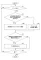
図8は、制御装置140が実行する処理を表すフローチャートを示す図である。制御装置140は、実施形態の報知装置の制御プログラムを実行することにより、図8に示す各ステップの処理を行う。 <Flowchart showing the process of the
Fig. 8 is a flowchart showing the process executed by the
制御部143は、処理をスタートさせると、イベントがあるかどうかを判定する(ステップS1)。制御部143は、イベントがない(S1:NO)と判定すると、ステップS1の処理を繰り返し実行する。When the
イベントがある(S1:YES)と制御部143が判定すると、信号切替部142は、加速度センサ130によって検出される外来振動の周波数が、信号出力部141が出力している駆動信号の駆動周波数について関連付けられている所定の周波数帯域に含まれるかどうかを判定する(ステップS2)。When the
信号切替部142は、外来振動の周波数が所定の周波数帯域に含まれない(S2:NO)と判定すると、デフォルトの周波数の駆動信号を信号出力部141に出力させる(ステップS3A)。これにより、アクチュエータ110は、発生しているイベントについてのデフォルトの周波数の駆動信号で駆動される。When the
また、信号切替部142は、ステップS2において、外来振動の周波数が所定の周波数帯域に含まれる(S2:YES)と判定すると、駆動信号の駆動周波数をホッピングさせて信号出力部141に出力させる(ステップS3B)。これにより、例えば、駆動信号の駆動周波数が駆動信号データ(図5参照)に含まれる複数の駆動周波数のうちの現在利用中ではない駆動周波数に変更される。In addition, when the
制御部143は、ステップS3A又はS3Bの処理が終了すると、駆動信号の駆動周波数は閾値周波数以上であるかどうかを判定する(ステップS4)。When processing of step S3A or S3B is completed, the
制御部143は、駆動信号の駆動周波数は閾値周波数以上である(S4:YES)と判定すると、打消信号を生成してスピーカ120に出力する(ステップS5)。制御部143は、メモリ144から打消信号データ(図6)を読み出し、現在のイベントの種類と、信号出力部141が現在出力している駆動信号の駆動周波数とに一致する信号パターンを用いて打消信号を生成すればよい。When the
ステップS5の処理が終了すると、制御装置140は、フローをステップS6に進行させる。Once processing of step S5 is completed, the
制御装置140は、一連の処理を終了するかどうかを判定する(ステップS6)。終了するのは、例えば、車両10のイグニッションスイッチがオフにされた場合である。The
制御装置140は、一連の処理を終了しない(S6:NO)と判定すると、フローをステップS1にリターンさせる。ステップS1から処理を続行するためである。一方、制御装置140は、一連の処理を終了する(S6:YES)と判定すると、一連の処理を終了する(エンド)。When the
以上のように、制御部143は、アクチュエータ110の振動に伴って生じる音波を打ち消す打消音波をスピーカ120から出力させるかどうかを、駆動信号の駆動周波数に基づいて決定する。このため、状態に応じて打消音波の出力制御が可能な報知装置100、報知装置の制御プログラム、及びシートシステム200を提供することができる。As described above, the
また、制御部143は、駆動信号の駆動周波数が閾値周波数以上である場合に、スピーカ120に打消音波を出力させるので、アクチュエータ110の振動に伴って生じる振動音波を効果的に打ち消すことができる。In addition, when the drive frequency of the drive signal is equal to or higher than the threshold frequency, the
また、駆動信号は、駆動周波数が高いほど大きい加速度でアクチュエータ110を振動させる信号である。人間の皮膚の感覚器官は、駆動周波数が高いほどアクチュエータ110の振動を感じ取りにくくなる。このため、駆動信号の加速度を駆動周波数が高いほど大きくすることで、報知装置100は、駆動周波数が高くなっても振動による触覚を安定的に利用者に呈示することができる。The drive signal is a signal that vibrates the
また、閾値周波数は、180Hz以上で220Hz以下である。アクチュエータ110の振動に伴って生じる音波が耳障りになる場合にスピーカ120に打消音波を出力させるので、報知装置100は、アクチュエータ110の振動に伴って生じる振動音波を効果的に打ち消すことができ、安定的に振動音波を打ち消すことができる。In addition, the threshold frequency is 180 Hz or more and 220 Hz or less. When the sound waves generated by the vibration of the
また、報知装置100は、アクチュエータ110が駆動していない状態で、振動を検出する加速度センサ130と、駆動信号の駆動周波数が加速度センサ130により検出された振動の周波数を含む所定の周波数帯域内にある場合に、駆動信号の駆動周波数が所定の周波数帯域から外れるように、駆動信号の駆動周波数を切り替える信号切替部142とを含む。制御部143は、信号切替部142によって切り替えられた駆動信号の駆動周波数が閾値周波数以上である場合に、スピーカ120に打消音波を出力させる。このため、報知装置100は、駆動信号の駆動周波数が外来振動の周波数と近くて利用者がアクチュエータ110の振動と外来振動とを区別できないような状態において、駆動信号の駆動周波数をホッピングさせることで外来振動とは異なる周波数の振動による触覚を呈示できる。また、ホッピングで変更した駆動周波数が閾値周波数以上である場合に、スピーカ120に打消音波を出力させるので、報知装置100は、アクチュエータ110の振動に伴って生じる振動音波を効果的に打ち消すことができる。The
また、打消音波は、アクチュエータ110の振動に伴って生じる音波に対して逆位相となる音波であるため、振動音波を打消音波で効果的に打ち消すことができる。報知装置100は、不要な振動音波による音を低減した状態で、利用者に対して振動による触覚を呈示することができる。報知装置100は、不要な音を低減することで、質感の高い振動による触覚を呈示することができる。In addition, since the cancelling sound waves are sound waves that are in the opposite phase to the sound waves generated by the vibration of the
また、駆動信号は、パルス波が継続するオン期間と、パルス波が存在しないオフ期間とを有する間欠駆動パターンを有する駆動信号である。打消音波は、オフ期間においては、アクチュエータ110の残振動に伴って生じる音波に対して逆位相となる音波である。このため、報知装置100は、オフ期間に残振動が生じる場合に残振動を打ち消すことによって、残振動による音波の発生を抑制し、質感の高い振動による触覚を呈示することができる。The drive signal is a drive signal having an intermittent drive pattern having an on period during which the pulse wave continues and an off period during which the pulse wave is not present. The cancelling sound wave is a sound wave that is in the opposite phase to the sound wave generated by the residual vibration of the
また、駆動信号は、周波数が50Hz以上で400Hz以下のパルス波が40ミリ秒以上にわたって継続するオン期間と、パルス波が存在しないオフ期間とを有する間欠駆動パターンを有する駆動信号である。このため、報知装置100は、振動音波を打消音波で打ち消しやすい周波数帯域の振動を生成でき、また、機械的に発生させた振動による触覚を利用者に呈示することができる。The drive signal has an intermittent drive pattern that includes an on period during which a pulse wave having a frequency of 50 Hz or more and 400 Hz or less continues for 40 milliseconds or more, and an off period during which no pulse wave is present. Therefore, the
また、スピーカ120は、シート11のような対象物に対して利用者の身体部位が位置する方向とは異なる方向に向けて打消音波を出力するので、報知装置100は、利用者の身体部位が位置する方向とは異なる方向に打消音波を出力でき、振動音波を効果的に打ち消すことができる。また、これにより、報知装置100は、質感の高い振動による触覚を呈示することができる。In addition, since the
以上、本開示の例示的な実施形態の報知装置、報知装置の制御プログラム、及びシートシステムについて説明したが、本開示は、具体的に開示された実施形態に限定されるものではなく、特許請求の範囲から逸脱することなく、種々の変形や変更が可能である。The above describes exemplary embodiments of the alarm device, the control program for the alarm device, and the seat system of the present disclosure. However, the present disclosure is not limited to the specifically disclosed embodiments, and various modifications and variations are possible without departing from the scope of the claims.
なお、本国際出願は、2021年10月25日に出願した日本国特許出願2021-173709に基づく優先権を主張するものであり、その全内容は本国際出願にここでの参照により援用されるものとする。This international application claims priority to Japanese patent application No. 2021-173709, filed on October 25, 2021, the entire contents of which are incorporated herein by reference.
10 車両
11 シート (対象物の一例)
100 報知装置
110 アクチュエータ
120 スピーカ (音出力部の一例)
130 加速度センサ (振動検出部の一例)
140 制御装置
141 信号出力部
142 信号切替部
143 制御部
144 メモリ
200 シートシステム 10
100: Notification device 110: Actuator 120: Speaker (an example of a sound output unit)
130 Acceleration sensor (an example of a vibration detection unit)
140
Claims (11)
Translated fromJapaneseイベントの種類に応じた駆動周波数の信号パターンを有する駆動信号を出力する信号出力部と、
前記駆動信号によって駆動されるアクチュエータと、
音波を出力する音出力部と、
前記アクチュエータの振動に伴って生じる音波を打ち消す打消音波を前記音出力部から出力させるかどうかを、前記駆動信号の駆動周波数に基づいて決定する制御部と
を含む、報知装置。 An alarm device that is attached to an object and that notifies a user who uses the object by providing a tactile sensation through vibration,
a signal output unit that outputs a drive signal having a signal pattern with a drive frequency according to a type of event;
an actuator driven by the drive signal;
A sound output unit that outputs sound waves;
a control unit that determines whether to cause the sound output unit to output a canceling sound wave that cancels a sound wave generated by vibration of the actuator, based on a drive frequency of the drive signal.
前記駆動信号の駆動周波数が前記振動検出部により検出された振動の周波数を含む所定の周波数帯域内にある場合に、前記駆動信号の駆動周波数が前記所定の周波数帯域から外れるように、前記駆動信号の駆動周波数を切り替える信号切替部と
をさらに含み、
前記制御部は、前記信号切替部によって切り替えられた前記駆動信号の駆動周波数が前記閾値周波数以上である場合に、前記音出力部に前記打消音波を出力させる、請求項2乃至4のいずれか1項に記載の報知装置。 a vibration detection unit that detects vibrations when the actuator is not being driven;
a signal switching unit that switches the drive frequency of the drive signal so that the drive frequency of the drive signal deviates from the predetermined frequency band when the drive frequency of the drive signal is within a predetermined frequency band including a frequency of the vibration detected by the vibration detection unit,
The alarm device according to claim 2 , wherein the control unit causes the sound output unit to output the canceling sound wave when a drive frequency of the drive signal switched by the signal switching unit is equal to or higher than the threshold frequency.
前記打消音波は、前記オフ期間においては、前記アクチュエータの残振動に伴って生じる音波に対して逆位相となる音波である、請求項6に記載の報知装置。 the drive signal is a drive signal having an intermittent drive pattern having an on period during which a pulse wave continues and an off period during which no pulse wave is present,
7. The alarm device according to claim 6, wherein the cancelling sound wave is a sound wave that has an opposite phase to a sound wave generated in association with residual vibration of the actuator during the off period.
振動を発生するアクチュエータと、
音波を出力する音出力部と
を含む報知装置を制御する報知装置の制御プログラムであって、
前記報知装置のコンピュータが、
イベントの種類に応じた駆動周波数の信号パターンを有する駆動信号を前記アクチュエータに出力して前記アクチュエータを振動させ、
前記アクチュエータの振動に伴って生じる音波を打ち消す打消音波を前記音出力部から出力させるかどうかを、前記駆動信号の駆動周波数に基づいて決定する、報知装置の制御プログラム。 An alarm device that is attached to an object and that notifies a user who uses the object by providing a tactile sensation through vibration,
An actuator that generates vibration;
A control program for controlling an alarm device including a sound output unit that outputs a sound wave,
The computer of the notification device
outputting a drive signal having a signal pattern with a drive frequency corresponding to a type of event to the actuator to vibrate the actuator;
a control program for an alarm device that determines, based on a drive frequency of the drive signal, whether to cause the sound output unit to output a canceling sound wave that cancels out a sound wave generated in association with vibration of the actuator;
振動による触覚の呈示により利用者に報知を行う報知装置と
を含むシートシステムであって、
前記報知装置は、
イベントの種類に応じた駆動周波数の信号パターンを有する駆動信号を出力する信号出力部と、
前記駆動信号によって駆動されるアクチュエータと、
音波を出力する音出力部と、
前記アクチュエータの振動に伴って生じる音波を打ち消す打消音波を前記音出力部から出力させるかどうかを、前記駆動信号の駆動周波数に基づいて決定する制御部と
を有する、シートシステム。 A seat,
and an alert device that alerts a user by providing a tactile sensation through vibration,
The notification device includes:
a signal output unit that outputs a drive signal having a signal pattern with a drive frequency according to a type of event;
an actuator driven by the drive signal;
A sound output unit that outputs sound waves;
a control unit that determines whether to output, from the sound output unit, a canceling sound wave that cancels a sound wave generated by vibration of the actuator, based on a drive frequency of the drive signal.
Applications Claiming Priority (3)
| Application Number | Priority Date | Filing Date | Title |
|---|---|---|---|
| JP2021173709 | 2021-10-25 | ||
| JP2021173709 | 2021-10-25 | ||
| PCT/JP2022/036968WO2023074269A1 (en) | 2021-10-25 | 2022-10-03 | Notification device, control program for notification device, and seat system |
Publications (2)
| Publication Number | Publication Date |
|---|---|
| JPWO2023074269A1 JPWO2023074269A1 (en) | 2023-05-04 |
| JP7652282B2true JP7652282B2 (en) | 2025-03-27 |
Family
ID=86157849
Family Applications (1)
| Application Number | Title | Priority Date | Filing Date |
|---|---|---|---|
| JP2023556245AActiveJP7652282B2 (en) | 2021-10-25 | 2022-10-03 | Notification device, notification device control program, and seat system |
Country Status (5)
| Country | Link |
|---|---|
| US (1) | US20240274111A1 (en) |
| JP (1) | JP7652282B2 (en) |
| CN (1) | CN118140487A (en) |
| DE (1) | DE112022005109T5 (en) |
| WO (1) | WO2023074269A1 (en) |
Citations (4)
| Publication number | Priority date | Publication date | Assignee | Title |
|---|---|---|---|---|
| JP2010258807A (en) | 2009-04-24 | 2010-11-11 | Nec Corp | Portable electronic apparatus, method for operating portable electronic apparatus, and operation program for portable electronic apparatus |
| JP2012105147A (en) | 2010-11-11 | 2012-05-31 | Panasonic Corp | Portable terminal device, vibration sound suppression method, and vibration sound suppression program |
| WO2013084958A1 (en) | 2011-12-06 | 2013-06-13 | 株式会社ニコン | Electronic device and vibration sound reduction method |
| WO2021044901A1 (en) | 2019-09-03 | 2021-03-11 | ソニー株式会社 | Control device, speaker device, and sound output method |
Family Cites Families (2)
| Publication number | Priority date | Publication date | Assignee | Title |
|---|---|---|---|---|
| JP2008077631A (en) | 2006-08-24 | 2008-04-03 | Toyota Central R&D Labs Inc | Seat, vehicle seat, and vehicle information presentation device |
| JP7505740B2 (en) | 2020-04-28 | 2024-06-25 | 国立大学法人秋田大学 | Method and device for measuring the concentration of aqueous solution using electromagnetic waves |
- 2022
- 2022-10-03CNCN202280070943.4Apatent/CN118140487A/enactivePending
- 2022-10-03JPJP2023556245Apatent/JP7652282B2/enactiveActive
- 2022-10-03WOPCT/JP2022/036968patent/WO2023074269A1/ennot_activeCeased
- 2022-10-03DEDE112022005109.4Tpatent/DE112022005109T5/enactivePending
- 2024
- 2024-04-15USUS18/635,169patent/US20240274111A1/enactivePending
Patent Citations (4)
| Publication number | Priority date | Publication date | Assignee | Title |
|---|---|---|---|---|
| JP2010258807A (en) | 2009-04-24 | 2010-11-11 | Nec Corp | Portable electronic apparatus, method for operating portable electronic apparatus, and operation program for portable electronic apparatus |
| JP2012105147A (en) | 2010-11-11 | 2012-05-31 | Panasonic Corp | Portable terminal device, vibration sound suppression method, and vibration sound suppression program |
| WO2013084958A1 (en) | 2011-12-06 | 2013-06-13 | 株式会社ニコン | Electronic device and vibration sound reduction method |
| WO2021044901A1 (en) | 2019-09-03 | 2021-03-11 | ソニー株式会社 | Control device, speaker device, and sound output method |
Also Published As
| Publication number | Publication date |
|---|---|
| US20240274111A1 (en) | 2024-08-15 |
| CN118140487A (en) | 2024-06-04 |
| JPWO2023074269A1 (en) | 2023-05-04 |
| DE112022005109T5 (en) | 2024-09-05 |
| WO2023074269A1 (en) | 2023-05-04 |
Similar Documents
| Publication | Publication Date | Title |
|---|---|---|
| US8217775B2 (en) | Method and device for warning the driver | |
| KR101013232B1 (en) | Malfunction informing device for vehicle and control program | |
| EP1780082A1 (en) | Active noise reducing device | |
| JP2008120115A (en) | Active vibration isolator | |
| WO2019230545A1 (en) | Vibration device, method for driving vibration device, program, and recording medium | |
| JP4033578B2 (en) | Sound generator driving circuit and operating sound generator | |
| JP2025076455A (en) | Vibration Control Device | |
| JP7652282B2 (en) | Notification device, notification device control program, and seat system | |
| KR102195441B1 (en) | apparatus for preventing drowsiness of driver using beta wave frequency-following effect | |
| JP2009137336A (en) | Car alarm system | |
| WO1994026555A1 (en) | Multi-sound vehicle horn system | |
| WO2023171078A1 (en) | Tactile presentation device, seat system, and tactile presentation method | |
| JPH08328570A (en) | Noise reduction device in the cab of a cab-over vehicle | |
| KR100558854B1 (en) | Horn recognition method for drivers with hearing impairment | |
| JP2017213243A (en) | Vibration control device | |
| JP3278172B2 (en) | Vehicle noise control device | |
| CN111071123A (en) | Vehicle seat | |
| JP7500308B2 (en) | Approach reporting system | |
| WO2025046730A1 (en) | Notification control method, notification control device, notification control program, and notification system | |
| JP3612735B2 (en) | Vehicle noise reduction device and control signal setting method | |
| JP3612734B2 (en) | Vehicle noise reduction device and control signal setting method | |
| JP2020063001A (en) | Vehicle seat | |
| JP2024139707A (en) | Vibration system for vehicles, vibration control method, vibration control program, and recording medium | |
| JP2023180836A (en) | Control device and control system | |
| JP2024106491A (en) | Vibration transmission device for seats and vibration transmission seat |
Legal Events
| Date | Code | Title | Description |
|---|---|---|---|
| A621 | Written request for application examination | Free format text:JAPANESE INTERMEDIATE CODE: A621 Effective date:20240228 | |
| TRDD | Decision of grant or rejection written | ||
| A01 | Written decision to grant a patent or to grant a registration (utility model) | Free format text:JAPANESE INTERMEDIATE CODE: A01 Effective date:20250212 | |
| A61 | First payment of annual fees (during grant procedure) | Free format text:JAPANESE INTERMEDIATE CODE: A61 Effective date:20250225 | |
| R150 | Certificate of patent or registration of utility model | Ref document number:7652282 Country of ref document:JP Free format text:JAPANESE INTERMEDIATE CODE: R150 |