JP7652187B2 - EGR estimation method and EGR estimation device for internal combustion engine - Google Patents
EGR estimation method and EGR estimation device for internal combustion engineDownload PDFInfo
- Publication number
- JP7652187B2 JP7652187B2JP2022511472AJP2022511472AJP7652187B2JP 7652187 B2JP7652187 B2JP 7652187B2JP 2022511472 AJP2022511472 AJP 2022511472AJP 2022511472 AJP2022511472 AJP 2022511472AJP 7652187 B2JP7652187 B2JP 7652187B2
- Authority
- JP
- Japan
- Prior art keywords
- egr
- intake
- passage
- internal combustion
- combustion engine
- Prior art date
- Legal status (The legal status is an assumption and is not a legal conclusion. Google has not performed a legal analysis and makes no representation as to the accuracy of the status listed.)
- Active
Links
Images


Classifications
- F—MECHANICAL ENGINEERING; LIGHTING; HEATING; WEAPONS; BLASTING
- F02—COMBUSTION ENGINES; HOT-GAS OR COMBUSTION-PRODUCT ENGINE PLANTS
- F02B—INTERNAL-COMBUSTION PISTON ENGINES; COMBUSTION ENGINES IN GENERAL
- F02B37/00—Engines characterised by provision of pumps driven at least for part of the time by exhaust
- F02B37/12—Control of the pumps
- F02B37/16—Control of the pumps by bypassing charging air
- F02B37/162—Control of the pumps by bypassing charging air by bypassing, e.g. partially, intake air from pump inlet to pump outlet
- F—MECHANICAL ENGINEERING; LIGHTING; HEATING; WEAPONS; BLASTING
- F02—COMBUSTION ENGINES; HOT-GAS OR COMBUSTION-PRODUCT ENGINE PLANTS
- F02D—CONTROLLING COMBUSTION ENGINES
- F02D41/00—Electrical control of supply of combustible mixture or its constituents
- F02D41/0002—Controlling intake air
- F02D41/0007—Controlling intake air for control of turbo-charged or super-charged engines
- F—MECHANICAL ENGINEERING; LIGHTING; HEATING; WEAPONS; BLASTING
- F02—COMBUSTION ENGINES; HOT-GAS OR COMBUSTION-PRODUCT ENGINE PLANTS
- F02D—CONTROLLING COMBUSTION ENGINES
- F02D41/00—Electrical control of supply of combustible mixture or its constituents
- F02D41/0025—Controlling engines characterised by use of non-liquid fuels, pluralities of fuels, or non-fuel substances added to the combustible mixtures
- F02D41/0047—Controlling exhaust gas recirculation [EGR]
- F02D41/0065—Specific aspects of external EGR control
- F02D41/0072—Estimating, calculating or determining the EGR rate, amount or flow
- F—MECHANICAL ENGINEERING; LIGHTING; HEATING; WEAPONS; BLASTING
- F02—COMBUSTION ENGINES; HOT-GAS OR COMBUSTION-PRODUCT ENGINE PLANTS
- F02M—SUPPLYING COMBUSTION ENGINES IN GENERAL WITH COMBUSTIBLE MIXTURES OR CONSTITUENTS THEREOF
- F02M26/00—Engine-pertinent apparatus for adding exhaust gases to combustion-air, main fuel or fuel-air mixture, e.g. by exhaust gas recirculation [EGR] systems
- F02M26/02—EGR systems specially adapted for supercharged engines
- F02M26/04—EGR systems specially adapted for supercharged engines with a single turbocharger
- F02M26/06—Low pressure loops, i.e. wherein recirculated exhaust gas is taken out from the exhaust downstream of the turbocharger turbine and reintroduced into the intake system upstream of the compressor
- F—MECHANICAL ENGINEERING; LIGHTING; HEATING; WEAPONS; BLASTING
- F02—COMBUSTION ENGINES; HOT-GAS OR COMBUSTION-PRODUCT ENGINE PLANTS
- F02M—SUPPLYING COMBUSTION ENGINES IN GENERAL WITH COMBUSTIBLE MIXTURES OR CONSTITUENTS THEREOF
- F02M26/00—Engine-pertinent apparatus for adding exhaust gases to combustion-air, main fuel or fuel-air mixture, e.g. by exhaust gas recirculation [EGR] systems
- F02M26/13—Arrangement or layout of EGR passages, e.g. in relation to specific engine parts or for incorporation of accessories
- F02M26/17—Arrangement or layout of EGR passages, e.g. in relation to specific engine parts or for incorporation of accessories in relation to the intake system
- F02M26/21—Arrangement or layout of EGR passages, e.g. in relation to specific engine parts or for incorporation of accessories in relation to the intake system with EGR valves located at or near the connection to the intake system
- F—MECHANICAL ENGINEERING; LIGHTING; HEATING; WEAPONS; BLASTING
- F02—COMBUSTION ENGINES; HOT-GAS OR COMBUSTION-PRODUCT ENGINE PLANTS
- F02M—SUPPLYING COMBUSTION ENGINES IN GENERAL WITH COMBUSTIBLE MIXTURES OR CONSTITUENTS THEREOF
- F02M26/00—Engine-pertinent apparatus for adding exhaust gases to combustion-air, main fuel or fuel-air mixture, e.g. by exhaust gas recirculation [EGR] systems
- F02M26/45—Sensors specially adapted for EGR systems
- F02M26/46—Sensors specially adapted for EGR systems for determining the characteristics of gases, e.g. composition
- F02M26/47—Sensors specially adapted for EGR systems for determining the characteristics of gases, e.g. composition the characteristics being temperatures, pressures or flow rates
- F—MECHANICAL ENGINEERING; LIGHTING; HEATING; WEAPONS; BLASTING
- F02—COMBUSTION ENGINES; HOT-GAS OR COMBUSTION-PRODUCT ENGINE PLANTS
- F02B—INTERNAL-COMBUSTION PISTON ENGINES; COMBUSTION ENGINES IN GENERAL
- F02B37/00—Engines characterised by provision of pumps driven at least for part of the time by exhaust
- F02B37/12—Control of the pumps
- F02B37/16—Control of the pumps by bypassing charging air
- F—MECHANICAL ENGINEERING; LIGHTING; HEATING; WEAPONS; BLASTING
- F02—COMBUSTION ENGINES; HOT-GAS OR COMBUSTION-PRODUCT ENGINE PLANTS
- F02M—SUPPLYING COMBUSTION ENGINES IN GENERAL WITH COMBUSTIBLE MIXTURES OR CONSTITUENTS THEREOF
- F02M26/00—Engine-pertinent apparatus for adding exhaust gases to combustion-air, main fuel or fuel-air mixture, e.g. by exhaust gas recirculation [EGR] systems
- F02M26/52—Systems for actuating EGR valves
- F02M26/64—Systems for actuating EGR valves the EGR valve being operated together with an intake air throttle
- Y—GENERAL TAGGING OF NEW TECHNOLOGICAL DEVELOPMENTS; GENERAL TAGGING OF CROSS-SECTIONAL TECHNOLOGIES SPANNING OVER SEVERAL SECTIONS OF THE IPC; TECHNICAL SUBJECTS COVERED BY FORMER USPC CROSS-REFERENCE ART COLLECTIONS [XRACs] AND DIGESTS
- Y02—TECHNOLOGIES OR APPLICATIONS FOR MITIGATION OR ADAPTATION AGAINST CLIMATE CHANGE
- Y02T—CLIMATE CHANGE MITIGATION TECHNOLOGIES RELATED TO TRANSPORTATION
- Y02T10/00—Road transport of goods or passengers
- Y02T10/10—Internal combustion engine [ICE] based vehicles
- Y02T10/12—Improving ICE efficiencies
- Y—GENERAL TAGGING OF NEW TECHNOLOGICAL DEVELOPMENTS; GENERAL TAGGING OF CROSS-SECTIONAL TECHNOLOGIES SPANNING OVER SEVERAL SECTIONS OF THE IPC; TECHNICAL SUBJECTS COVERED BY FORMER USPC CROSS-REFERENCE ART COLLECTIONS [XRACs] AND DIGESTS
- Y02—TECHNOLOGIES OR APPLICATIONS FOR MITIGATION OR ADAPTATION AGAINST CLIMATE CHANGE
- Y02T—CLIMATE CHANGE MITIGATION TECHNOLOGIES RELATED TO TRANSPORTATION
- Y02T10/00—Road transport of goods or passengers
- Y02T10/10—Internal combustion engine [ICE] based vehicles
- Y02T10/40—Engine management systems
Landscapes
- Engineering & Computer Science (AREA)
- Chemical & Material Sciences (AREA)
- Combustion & Propulsion (AREA)
- Mechanical Engineering (AREA)
- General Engineering & Computer Science (AREA)
- Physics & Mathematics (AREA)
- Fluid Mechanics (AREA)
- Analytical Chemistry (AREA)
- Exhaust-Gas Circulating Devices (AREA)
Description
Translated fromJapanese本発明は、内燃機関のEGR推定に関する。The present invention relates to EGR estimation in an internal combustion engine.
JP2013-7268A、WO2012/176490A1には、リサーキュレーションバルブが開いたときにEGRガスを含む新気がエアフロメータまで吹き返さないようにする過給機付内燃機関の吸気装置が開示されている。リサーキュレーションバルブは、スロットル弁の閉時にコンプレッサ下流の圧力をコンプレッサ上流へ解放する。JP2013-7268A and WO2012/176490A1 disclose an intake device for a supercharged internal combustion engine that prevents fresh air containing EGR gas from blowing back to the air flow meter when the recirculation valve is open. The recirculation valve releases pressure downstream of the compressor to the upstream of the compressor when the throttle valve is closed.
過給時にリサーキュレーションバルブを開けると、ガスがエアクリーナ付近まで逆流することがある。このためこの場合は、EGRガスを逆流させないようEGRバルブを全閉にすることが考えられる。しかしながらこのようにしてEGRを停止しても、すでに吸気通路に存在するEGRガスは吸気通路を逆流し、その後内燃機関の筒内に流れることになる。このため、逆流したEGRガスがどのように筒内に流入するかを把握し、より正確なEGR率を推定することが望まれる。When the recirculation valve is opened during supercharging, gas may flow back up to the vicinity of the air cleaner. For this reason, in this case, it is considered to fully close the EGR valve to prevent the EGR gas from flowing back. However, even if EGR is stopped in this way, the EGR gas already present in the intake passage will flow back through the intake passage and then into the cylinders of the internal combustion engine. For this reason, it is desirable to understand how the backflowing EGR gas flows into the cylinders and to estimate the EGR rate more accurately.
本発明はこのような課題に鑑みてなされたもので、過給時にリサーキュレーションバルブを開けてEGRバルブを全閉にする場合に、より正確なEGR率を推定することを目的とする。The present invention has been made in consideration of such problems, and aims to estimate the EGR rate more accurately when the recirculation valve is opened and the EGR valve is fully closed during supercharging.
本発明のある態様の内燃機関のEGR推定方法は、エアクリーナとエアクリーナ及び内燃機関を接続する吸気通路とを含む吸気系と、内燃機関に接続する排気通路を含む排気系と、吸気通路及び排気通路に設けられた過給機とを備える内燃機関の吸排気系であって、吸気通路及び排気通路を接続するEGR通路とEGR通路に設けられたEGRバルブとを含むEGR装置が設けられるとともに、吸気系は当該吸気系における過給機の上流圧部分及び下流圧部分を接続する吸気バイパス通路と吸気バイパス通路に設けられたリサーキュレーションバルブとを含む内燃機関の吸排気系において、吸気通路の過給機から前記EGR通路が接続するEGR合流部までの範囲におけるいずれかの位置のEGR率を推定する内燃機関のEGR推定方法であって、EGRガスがエアクリーナ側に逆流するように過給時にリサーキュレーションバルブを開け且つEGRバルブを全閉にし、EGRバルブを全閉にしてから所定時間経過するまでの間に、リサーキュレーションバルブを開ける前の吸気通路のEGR率に基づいて、吸気通路のEGR率を推定する。 An EGR estimation method for an internal combustion engine according to one aspect of the present invention is an intake and exhaust system of an internal combustion engine including an intake system including an air cleaner and an intake passage connecting the air cleaner and the internal combustion engine, an exhaust system including an exhaust passage connected to the internal combustion engine, and a supercharger provided in the intake passage and the exhaust passage, the intake system being provided with an EGR device including an EGR passage connecting the intake passage and the exhaust passage and an EGR valve provided in the EGR passage, and the intake system being provided with an intake bypass passage connecting an upstream pressure portion and a downstream pressure portion of the supercharger in the intake system and an EGR valve provided in the intake bypass passage. An EGR estimation method for an internal combustion engine, which estimates the EGR rate atany position in the range from a turbocharger in an intake passage to an EGR junction where the EGR passage is connected in an intake and exhaust system of an internal combustion engine including a recirculation valve, wherein the recirculation valve is opened and the EGR valve is fully closed during supercharging so that EGR gas flows back to the air cleaner side, and the EGR rate of the intake passage is estimated based on the EGR rate of the intake passage before the recirculation valve was opened during a predetermined time period from when the EGR valve was fully closed.
本発明の別の態様によれば、上記内燃機関のEGR推定方法に対応する内燃機関のEGR推定装置が提供される。According to another aspect of the present invention, there is provided an EGR estimation device for an internal combustion engine corresponding to the above-mentioned EGR estimation method for an internal combustion engine.
以下、添付図面を参照しながら本発明の実施形態について説明する。Below, an embodiment of the present invention is described with reference to the attached drawings.
図1は、車両の要部を示す図である。車両は、内燃機関1と、吸気系10と、排気系20と、過給機30と、EGR装置40と、コントローラ50とを備える。Figure 1 is a diagram showing the main parts of a vehicle. The vehicle includes an
吸気系10は、吸気通路11と、エアクリーナ12と、エアフロメータ13と、吸気絞り弁14と、インタークーラ15と、スロットルバルブ16と、コレクタ17と、コンプレッサ31と、吸気バイパス通路18と、リサーキュレーションバルブ(以下、R/Vと称す)19とを備える。吸気通路11は、エアクリーナ12と内燃機関1とを接続し、内燃機関1に導入する吸気を流通させる。吸気通路11には、エアクリーナ12、エアフロメータ13、吸気絞り弁14、コンプレッサ31、インタークーラ15、スロットルバルブ16及びコレクタ17が上流側からこの順に設けられる。The
エアクリーナ12は、吸気に含まれる異物を除去する。エアフロメータ13は、吸気の流量を計測する。吸気絞り弁14は、吸気通路11のうち後述するEGR通路41が接続するEGR合流部11aよりも上流側の部分に設けられる。吸気絞り弁14は開度を低下させることにより、EGR通路41を介した排気の還流量を増加させる。The
インタークーラ15は、過給された吸気を冷却する。スロットルバルブ16は、内燃機関1に導入する吸気の量を調節する。コレクタ17は、吸気を一時的に貯留する。コンプレッサ31は過給機30のコンプレッサであり、吸気を圧縮する。The
排気系20は、排気通路21と、上流触媒22と、下流触媒23と、タービン32とを備える。排気通路21は内燃機関1に接続し、内燃機関1から排出される排気を流通させる。排気通路21には、タービン32、上流触媒22及び下流触媒23が上流側からこの順に設けられる。上流触媒22及び下流触媒23は排気を浄化する。タービン32は過給機30のタービンであり、排気からエネルギを回収する。The
過給機30は吸気を圧縮して内燃機関1に供給する。過給機30はターボチャージャであり、コンプレッサ31と、タービン32と、シャフト33とを備える。過給機30は、コンプレッサ31が吸気通路11に、タービン32が排気通路21にそれぞれ設けられることで、吸気通路11及び排気通路21に設けられる。過給機30では、タービン32が排気によって回転することで、シャフト33を介してコンプレッサ31が回転し、吸気を圧縮する。コンプレッサ31においては、背中合わせの向きに配置された一対のコンプレッサホイールがシャフト33に設けられており、一対のコンプレッサホイールにより吸気の圧縮が行われる。タービン32には排気バイパス通路が設けられ、排気バイパス通路には流通する排気の流量を調節するウェイストゲートバルブ(図示省略)が設けられる。The
EGR装置40は、EGR通路41と、EGRクーラ42と、EGRバルブ43とを備える。EGR装置40は、排気通路21から吸気通路11に排気を還流する。The EGR
EGR通路41は、排気通路21と吸気通路11とを接続する。EGR通路41は、排気通路21を流通する排気の一部をEGRガスとして吸気通路11に還流する。EGR通路41にはEGRクーラ42とEGRバルブ43とが設けられる。EGRクーラ42は、EGR通路41を流通するEGRガスを冷却する。EGRバルブ43は、EGR通路41を流通するEGRガスの流量を調節する。The EGR
EGR装置40、具体的にはEGR通路41は、排気通路21のうち過給機30つまりタービン32よりも下流の部分と、吸気通路11のうち過給機30つまりコンプレッサ31よりも上流の部分とを接続する。このように吸気通路11と排気通路21とを接続するEGR通路41は、LPLすなわちロープレッシャーループのEGR経路を形成する。EGR通路41はさらに具体的には、排気通路21のうち上流触媒22及び下流触媒23間の部分と、吸気通路11のうち吸気絞り弁14及びコンプレッサ31間の部分とを接続する。The EGR
吸気バイパス通路18は、吸気系10における過給機30の上流圧部分及び下流圧部分を接続する。上流圧部分は過給機30より上流側、且つEGR合流部11aより下流側の部分の吸気通路11とされる。下流圧部分は過給機30より下流側、且つインタークーラ15より上流側の部分の吸気通路11とされる。吸気系10における過給機30の下流圧部分に接続することは、圧縮された吸気が吸気バイパス通路18に流入できるようにコンプレッサ31に接続することを含む。The
R/V19は吸気バイパス通路18に設けられる。R/V19は開閉弁により構成される。過給時には、過給機30の上流圧よりも下流圧が高い。このため、過給機時にR/V19が開くと、コンプレッサ31で圧縮された吸気が、吸気バイパス通路18を介して過給機30よりも上流側の部分の吸気通路11に戻される。The R/
コントローラ50は電子制御装置であり、コントローラ50には各種センサ・スイッチ類として、エアフロメータ13のほか、クランク角センサ71やアクセル開度センサ72や過給圧センサ73や大気圧センサ74等からの信号が入力される。クランク角センサ71は、所定クランク角ごとにクランク角信号を生成する。クランク角信号は、内燃機関1の回転速度NEを代表する信号として用いられる。アクセル開度センサ72は、車両のアクセルペダルの踏込量を検出する。アクセルペダルの踏込量は、内燃機関1の負荷を代表する信号として用いられる。過給圧センサ73は吸気通路11における過給機30の下流圧を検出し、大気圧センサ74は大気圧を検出する。The
コントローラ50は、上述した各種センサ・スイッチ類からの入力信号に基づいて、内燃機関1のほか、吸気絞り弁14やスロットルバルブ16やR/V19やEGRバルブ43を制御する。コントローラ50は、機関運転状態に応じて点火時期や燃料噴射量を制御することにより、内燃機関1を制御する。機関運転状態は例えば回転速度NEや負荷である。Based on input signals from the various sensors and switches described above, the
ところで、過給時にR/V19を開けると、ガスがエアクリーナ12付近まで逆流することがある。このためこの場合は、EGRガスを逆流させないようEGRバルブ43を全閉にすることが考えられる。しかしながらこのようにしてEGRを停止しても、すでに吸気通路11に存在するEGRガスは吸気通路11を逆流し、その後内燃機関1の筒内に流れることになる。However, if the R/
このため、本実施形態では逆流したEGRガスがどのように筒内に流入するかを把握し、把握した流入態様に基づきEGR率(実EGR率)を推定する。For this reason, in this embodiment, the manner in which the backflowing EGR gas flows into the cylinder is grasped, and the EGR rate (actual EGR rate) is estimated based on the grasped inflow pattern.
図2Aから図2Dは、EGRガスの流動態様の説明図である。図2Aから図2Dでは、エアフロメータ13、R/V19等は図示省略している。図2Aは、過給時にR/V19を開く直前の状態を示す。このときには、EGR合流部11aから下流側の吸気通路11は、吸気との混合ガスからなる目標EGR率のEGRガスで満たされた状態になっている。Figures 2A to 2D are explanatory diagrams of the flow patterns of EGR gas. The
図2Bは、過給時にR/V19を開け、EGRバルブ43を全閉にしたときの状態を示す。このとき、コンプレッサ31で圧縮された混合ガスは吸気バイパス通路18を介してコンプレッサ31より上流側の吸気通路11に戻され、さらにエアクリーナ側つまりEGR合流部11aよりも上流側に逆流してエアクリーナ12に吹き抜ける。これにより、エアクリーナ12では混合ガスが空気により希釈された状態になる。結果、EGR率がエアクリーナ12の出口位置でステップ的に低下し、さらに上流側に向かって次第に低下する。Figure 2B shows the state when the R/
図2Cは、EGR合流部11aからエアクリーナ12との接続部までの吸気通路11の容積(以下、上流配管容積と称す)分の流量Q2が再吸入されたときの状態を示す。このときには、希釈された混合ガスがEGR合流部11a直前に到達する結果、EGR率がステップ的に低下する段差がEGR合流部11a直前に位置することになる。2C shows the state when a flow rate Q2 equivalent to the volume of the
図2Dは、希釈された混合ガスがEGR合流部11aを越えて再吸入されていく状態を示す。このとき、EGR合流部11aでは、希釈された混合ガスによりEGR率が次第に低下する。Figure 2D shows the state in which the diluted mixture gas passes through the
このような混合ガスの流動態様に鑑み、本実施形態ではエアクリーナ12側に逆流したガスの量(以下、EGRガスの逆流量と称す)に基づいてEGR合流部11aにおけるEGR率を推定する。In consideration of this flow pattern of the mixed gas, in this embodiment, the EGR rate at the
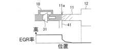
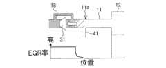
図3は、EGR率の推定方法の説明図である。破線は目標EGR率を示す。Figure 3 is an explanatory diagram of a method for estimating the EGR rate. The dashed line indicates the target EGR rate.
タイミングT1では、R/V19が開かれる。このときには、EGRバルブ43が全閉とされEGRは停止されるが、図2Bを用いて前述したように混合ガスの吹き返しが生じる。結果、EGR合流部11aのEGR率は破線で示されるゼロにはならず、タイミングT1でそのままとなる。At timing T1, the R/
タイミングT2では、上流配管容積分の流量Q2が再吸入される。図2Cを用いて前述したように、EGR合流部11aのEGR率は、上流配管容積分の流量Q2が再吸入されるタイミングT2までそのままとなる。At timing T2, the flow rate Q2 of the upstream piping volume is re-inhaled. As described above with reference to FIG. 2C, the EGR rate at the
EGRガスの逆流量が大きいと、上流配管容積分の流量Q2が再吸入されるまでの時間は長くなる。このため、タイミングT2はEGRガスの逆流量に応じて変化する。結果、タイミングT1、タイミングT2間の時間として示される所定時間αは、EGRガスの逆流量が大きいほど長くなる。所定時間αは、R/V19が開いてから上流配管容積分の流量Q2が再吸入されるまでの時間であり、EGRガスの逆流量に応じて変更される。If the amount of backflow of EGR gas is large, the time until the flow rate Q2 of the upstream piping volume is re-inhaled becomes longer. For this reason, timing T2 changes according to the amount of backflow of EGR gas. As a result, the predetermined time α, which is indicated as the time between timing T1 and timing T2, becomes longer as the amount of backflow of EGR gas becomes larger. The predetermined time α is the time from when R/
このため本実施形態では、タイミングT1からタイミングT2までは、上流配管容積を適合要素として、R/V19を開けてEGRバルブ43を全閉にしても、所定時間αが経過するまでは、EGR合流部11aのEGR率をR/V19を開く直前の目標EGR率にホールドする第1プロフィールProf1により、推定するEGR率が設定される。Therefore, in this embodiment, from timing T1 to timing T2, the upstream piping volume is used as an adaptation element, and even if R/V19 is opened and
図2C、図2Dを用いて前述したように、タイミングT2直後からは、EGR合流部11aにおけるEGR率は、エアクリーナ12内にEGRガスが逆流した際のエアクリーナ12内のEGR率によって表される。このため、タイミングT2直後からは、EGR合流部11aにおけるEGR率が、上述したエアクリーナ12内のEGR率に基づき推定される。2C and 2D, immediately after timing T2, the EGR rate at the
タイミングT2直後には、図2Cを用いて前述したようにEGR合流部11aにおけるEGR率はステップ的に低下する。このときのEGR率は、エアクリーナ12に吹き返した混合ガスの量が大きいほど、混合ガスが希釈され難くなることから高くなる。また、エアクリーナ12に吹き返す混合ガスの量は、EGRガスの逆流量が大きいほど大きくなる。従ってこのときのEGR率は、EGRガスの逆流量が大きいほど高くなる。Immediately after timing T2, the EGR rate at the
このため本実施形態では、EGRガスの逆流量を適合要素として、第1プロフィールProf1に続いてEGR率をステップ的に低下させるとともに、EGRガスの逆流量が大きいほどステップ的に低下させるEGR率を高くする第2プロフィールProf2により、推定するEGR率が設定される。For this reason, in this embodiment, the estimated EGR rate is set by using the backflow amount of EGR gas as an adaptation element, and by using a second profile Prof2 in which the EGR rate is reduced in a stepwise manner following the first profile Prof1, and the greater the backflow amount of EGR gas, the higher the EGR rate that is reduced in a stepwise manner.
EGR率がステップ的に低下されてからは、図2Dを用いて前述したようにEGR合流部11aにおけるEGR率は希釈された混合ガスにより次第に低下する。また、このときのEGR率の低下量は再吸入されるガス流量に応じて変化し、再吸入されるガス流量が大きいほど大きくされる。これは、再吸入されるガス流量が大きいほど、希釈された混合ガスがEGR合流部11aを早く通過し、EGR率の低下が早まるためである。After the EGR rate is reduced in a stepwise manner, the EGR rate at the
このため本実施形態では、再吸入されるガス流量を適合要素として、第2プロフィールProf2に続いてEGR率を時間経過とともに低下させ、EGR率の低下量を再吸入されるガス流量に応じて低下させる第3プロフィールProf3により、推定するEGR率が設定される。Therefore, in this embodiment, the estimated EGR rate is set by the third profile Prof3, which uses the re-breathed gas flow rate as an adaptation element, reduces the EGR rate over time following the second profile Prof2, and reduces the amount of reduction in the EGR rate according to the re-breathed gas flow rate.
第3プロフィールProf3は、再吸入されるガス流量に応じて一時応答遅れでEGR率を変化させるプロフィールとされる。第3プロフィールProf3におけるEGR率の低下量は、再吸入されるガス流量に応じて時定数を変化させることにより変化させることができる。The third profile Prof3 is a profile that changes the EGR rate with a temporary response delay according to the re-breathed gas flow rate. The amount of reduction in the EGR rate in the third profile Prof3 can be changed by changing the time constant according to the re-breathed gas flow rate.
図4は、コントローラ50が行うEGR率の推定処理を示す制御ブロック図である。通過量算出部51は、R/V19を通過するガスの通過量を算出する。当該通過量は、R/V19を通過するガスの通過流量に推定処理のJOB周期を乗算することにより算出され、吹返しが発生している場合に負の値とされる。R/V19を通過するガスの通過流量は例えば、コンプレッサ31の過給圧及び大気圧、吸気バイパス通路18の断面積に基づき算出できる。算出されたガスの通過量は積算値算出部52に入力される。Figure 4 is a control block diagram showing the EGR rate estimation process performed by the
積算値算出部52は、吹返し量積算値QSを算出する。吹返し量積算値QSは、入力されたガスの通過量と前回算出したガスの吹返し量積算値QSとを足し合わせることで算出される。算出された吹返し量積算値QSは、第1判定部53と積算値ピーク値算出部56と順流量算出部57とに入力される。The integrated
第1判定部53は、入力された吹返し量積算値QSがゼロより小さいか否かを判定する。吹返しが発生している場合、吹返し量積算値QSは負の値となり、肯定判定される。この場合、第1判定部53からAND回路部54に信号が入力される。The
AND回路部54は、第1判定部53及び後述する第2判定部58それぞれから信号が入力された場合に、EGR率ホールド部55にAND信号を入力する。第1判定部53からの信号は吹返しが発生していることを指標し、第2判定部58からの信号はR/V19を開いてから上流配管容積分の流量Q2が未だ再吸入されていないことを指標する。従って、AND信号は、吹返しが発生しており且つ上流配管容積分の流量Q2が未だ再吸入されていないことを指標する。The AND
EGR率ホールド部55は、ホールドするEGR率の設定、つまり第1プロフィールProf1に基づくEGR率の設定を行う。EGR率ホールド部55は、AND信号が入力されない場合に目標EGR率を選択する。これにより、EGR率が目標EGR率に設定される。The EGR
EGR率ホールド部55は、AND信号が入力された場合に前回設定したEGR率を選択し処理を停止する。これにより、ホールドするEGR率が設定される。設定されたEGR率は、段差変化設定部59とEGR率選択部60とに入力される。When an AND signal is input, the EGR
積算値ピーク値算出部56は、吹返し量積算値QSのピーク値である積算値ピーク値QSmaxを算出する。積算値ピーク値算出部56は、入力された吹返し量積算値QSが前回算出した積算値ピーク値QSmax以下の場合(絶対値で積算値ピーク値QSmax以上の場合)に、入力された吹返し量積算値QSを選択する。これにより、選択された吹返し量積算値QSが新たな積算値ピーク値QSmaxとして更新され、暫定的な積算値ピーク値QSmaxが算出される。The integrated peak
積算値ピーク値算出部56は、入力された吹返し量積算値QSが前回算出した積算値ピーク値QSmaxより大きい場合(絶対値で積算値ピーク値QSmaxより小さい場合)に、前回算出した積算値ピーク値QSmaxを選択し処理を停止する。これにより、前回算出した積算値ピーク値QSmaxが、演算上の真の積算値ピーク値QSmaxとして算出及び確定される。真の積算値ピーク値QSmaxは換言すればEGRガスの逆流量であり、混合ガスの吹返し総流量を指標する。算出された積算値ピーク値QSmaxは、順流量算出部57と段差変化設定部59とに入力される。If the input cumulative amount QS is greater than the cumulative amount peak value QSmax calculated last time (or less than the cumulative amount peak value QSmax in absolute value), the cumulative amount peak
順流量算出部57は、吹返し分順流量Q1を算出する。吹返し分順流量Q1は換言すれば再吸入されるガス流量であり、積算値ピーク値QSmaxと吹返し量積算値QSとに基づき算出される。具体的には、吹返し分順流量Q1は正負の符号を逆にした積算値ピーク値QSmaxに吹返し量積算値QSを正負の符号そのままで加算することにより算出される。算出された吹返し分順流量Q1は第2判定部58に入力される。The forward
第2判定部58は、吹返し分順流量Q1が上流配管容積分の流量Q2以下か否かを判定する。吹返し分順流量Q1は、R/V19を開いてから上流配管容積分の流量Q2が未だ再吸入されていない場合に、上流配管容積分の流量Q2以下となる。肯定判定の場合、第2判定部58からは、AND回路部54とEGR率選択部60と応答遅れ演算部62とに信号が入力される。The
段差変化設定部59は、積算値ピーク値QSmaxと回転速度NEとに基づきEGR率の段差率(減少度合い)を演算する。EGR率の段差率は、積算値ピーク値QSmaxが大きいほど小さく演算され、また、回転速度NEが小さいほど小さく演算される。これは、エアクリーナ12でEGR率に段差変化が生じるところ、エアクリーナ12に吹き返す混合ガスの量は、EGRガスの逆流量、さらには吸気を行う内燃機関1の回転速度NEに依存するためである。The step
段差変化設定部59はさらに、演算した段差率をEGR率ホールド部55から入力されたEGR率に乗算する。これにより、EGR率に段差変化が設定され、第2プロフィールProf2に基づくEGR率が設定される。設定されたEGR率は、EGR率選択部60に入力される。The step
EGR率選択部60は、第2判定部58から信号が入力されている場合、つまりR/V19を開いてから上流配管容積分の流量Q2が未だ再吸入されていない場合に、EGR率ホールド部55から入力されたEGR率を選択する。従ってこの場合には、第1プロフィールProf1に基づくEGR率が選択される。When a signal is input from the
EGR率選択部60は、第2判定部58から信号が入力されていない場合、つまり上流配管容積分の流量Q2が再吸入された場合に、段差変化設定部59から入力されたEGR率を選択し処理を停止する。これにより、第1プロフィールProf1に基づくEGR率から切り替えられるかたちで、第2プロフィールProf2に基づくEGR率が選択される。選択されたEGR率は、応答遅れ演算部62に入力される。When no signal is input from the
応答遅れフィルタ設定部61は、回転速度NEと新気流量とに基づきEGR率の応答遅れフィルタの時定数を算出する。新気流量は、エアフロメータ13からの信号に基づき検出できる。EGR率の応答遅れは、回転速度NEが高いほど、また、新気流量が大きいほど小さく設定される。これは、回転速度NEが高いほど、また、新気流量が大きいほど、再吸入されるガス流量が大きく、希釈された混合ガスがEGR合流部11aを早く通過することから、EGR率の低下が早まるためである。算出された応答遅れフィルタの時定数は、応答遅れ演算部62に入力される。The response delay
応答遅れ演算部62は、第2判定部58から信号が入力されていない場合、つまり上流配管容積分の流量Q2が再吸入された場合に、EGR率選択部60から入力されたEGR率に応答遅れフィルタ設定部61から入力された応答遅れフィルタの時定数を適用する。これにより、EGR率の応答遅れが演算され、EGR率に反映される。応答遅れが反映されたEGR率は、EGR率決定部63に入力される。When no signal is input from the
第2判定部58から信号が入力されている場合、つまりR/V19を開いてから上流配管容積分の流量Q2が未だ再吸入されていない場合、応答遅れ演算部62は、EGR率の応答遅れを演算しない。この場合、EGR率選択部60から入力されたEGR率がそのままEGR率決定部63に入力される。When a signal is input from the
EGR率決定部63は、入力されたEGR率をEGR合流部11aのEGR率として決定する。これにより、過給時にR/V19を開け、EGRバルブ43を全閉にした際のEGR合流部11aにおけるEGR率が、第1プロフィールProf1から第3プロフィールProf3に従って推定される。The EGR
図5は、コントローラ50が行うEGR率の推定処理をフローチャートで示す図である。コントローラ50は本フローチャートに示す処理を実行するようにプログラムされることで、制御部を有した構成とされる。Figure 5 is a flowchart showing the EGR rate estimation process performed by the
ステップS1で、コントローラ50は吹返し量積算値QSを算出する。吹返し量積算値QSは、図4を用いて前述したように算出できる。In step S1, the
ステップS2で、コントローラ50はR/V19が作動中か否か、つまりR/V19が開いているか否かを判定する。ステップS2で否定判定であれば、処理はステップS6に進む。In step S2, the
ステップS6で、コントローラ50は吹返し量積算値QSがゼロより小さいか否かを判定する。ステップS6では、吹返し量積算値QSがゼロより小さい場合に吹返しが発生していると判断される。In step S6, the
R/V19が閉じている場合、吹返しは発生していない。このため、ステップS2の否定判定に続いてステップS6に処理が進んだ場合は、ステップS6で否定判定され、処理はステップS7に進む。If the R/
ステップS7で、コントローラ50はEGR合流部11aにおけるEGR率を目標EGR率とする。これにより、R/V19が開く前にはEGR合流部11aにおけるEGR率が目標EGR率とされる。ステップS7の後には処理は一旦終了する。In step S7, the
その後のルーチンでR/V19が開いた場合にはステップS2で肯定判定され、処理はステップS3に進む。If R/V19 is opened in a subsequent routine, a positive judgment is made in step S2 and processing proceeds to step S3.
ステップS3及び続くステップS4で、コントローラ50は積算値ピーク値QSmaxと吹返し分順流量Q1とを算出する。積算値ピーク値QSmaxと吹返し分順流量Q1とは図4を用いて前述したように算出できる。In step S3 and the subsequent step S4, the
ステップS5で、コントローラ50は吹返し分順流量Q1が上流配管容積分の流量Q2以下か否かを判定する。ステップS5で肯定判定であれば、R/V19を開いてから上流配管容積分の流量Q2が未だ再吸入されていないと判断され、処理はステップS6に進む。In step S5, the
ステップS5の肯定判定に続いてステップS6に処理が進んだ場合、吹返し量積算値QSはゼロより小さくなり、ステップS6で肯定判定される。この場合、処理はステップS8に進む。If the process proceeds to step S6 following a positive determination in step S5, the cumulative amount of backflow QS becomes less than zero, and a positive determination is made in step S6. In this case, the process proceeds to step S8.
ステップS8で、コントローラ50はEGR合流部11aにおけるEGR率を前回値にホールドする。つまり、ステップS8ではEGR率を推定するにあたり、第1プロフィールProf1が適用される。ステップS8の後には処理は一旦終了する。In step S8, the
その後のルーチンでは、R/V19が作動中で且つ吹返し分順流量Q1が上流配管容積分の流量Q2より大きくなるまでの間は、ステップS2、ステップS5で肯定判定され、続くステップS6でも肯定判定される。結果、EGR合流部11aにおけるEGR率は前回値にホールドされたままとなる。In the subsequent routine, while the R/
R/V19が作動中で且つ吹返し分順流量Q1が上流配管容積分の流量Q2より大きくなると、R/V19が開いてから上流配管容積分の流量Q2が再吸入されたと判断され、ステップS5で否定判定される。この場合、処理はステップS9に進む。When the R/
ステップS9で、コントローラ50は前回のルーチンでEGR率に段差変化を設定したか否かを判定する。ステップS9で否定判定であれば、処理はステップS10に進む。In step S9, the
ステップS10で、コントローラ50はEGR合流部11aにおけるEGR率に段差変化を設定する。つまり、ステップS10ではEGR率を推定するにあたり、第2プロフィールProf2が適用される。ステップS10の後には、処理は一旦終了する。この場合、ステップS10の処理を行ったルーチンの1JOB後となる次のルーチンにおいて、ステップS9で肯定判定され、処理はステップS11に進む。In step S10, the
ステップS11で、コントローラ50はEGR率を1次応答遅れで低下させる。つまり、ステップS11ではEGR率を推定するにあたり、第3プロフィールProf3が適用される。ステップS11後には、本フローチャートの処理は一旦終了する。In step S11, the
次に本実施形態の主な作用効果について説明する。Next, we will explain the main effects of this embodiment.
本実施形態にかかる内燃機関1のEGR推定方法は、エアクリーナ12と吸気通路11とを含む吸気系10と、排気通路21を含む排気系20と、過給機30とを備える内燃機関1の吸排気系10、20であって、EGR通路41とEGRバルブ43とを含むEGR装置40が設けられるとともに、吸気系10は吸気バイパス通路18とR/V19とを備える内燃機関1の吸排気系10、20において、EGR合流部11aにおけるEGR率を推定する。内燃機関1のEGR推定方法は、過給時にR/V19を開けてEGRバルブ43を全閉にする場合に、R/V19を開けることによりエアクリーナ12側に逆流したEGRガスの逆流量に基づいて、EGR合流部11aにおけるEGR率を推定する。The EGR estimation method for the
このような方法によれば、図2Aから図2Dを用いて前述したEGRガスの流動態様に照らし、過給時にR/V19を開けてEGRバルブ43を全閉にする場合に、より正確なEGR率を推定することができる。According to this method, in light of the flow patterns of EGR gas described above using Figures 2A to 2D, a more accurate EGR rate can be estimated when the R/
内燃機関1のEGR推定方法では、R/V19を開けてEGRバルブ43を全閉にしても、所定時間αが経過するまでは、推定されるEGR率であるEGR合流部11aにおけるEGR率として、EGRバルブ43を全閉にする前のEGR率を用いることにより、EGR率が推定される。つまり、EGR率を推定するにあたり第1プロフィールProf1が適用される。In the EGR estimation method for the
このような方法によれば、図2B、図2Cを用いて前述したEGRガスの流動態様に照らし、EGR率をホールドすることでより正確なEGR率を推定することができる。According to this method, a more accurate EGR rate can be estimated by holding the EGR rate in light of the flow pattern of the EGR gas described above using Figures 2B and 2C.
このような方法では、所定時間αはEGRガスの逆流量に応じて変更される。In this method, the predetermined time α is varied depending on the amount of backflow of EGR gas.
このような方法によれば、EGR率を適切な時間ホールドすることができるので、より正確なEGR率を推定することができる。This method allows the EGR rate to be held for an appropriate period of time, making it possible to estimate the EGR rate more accurately.
内燃機関1のEGR推定方法では、所定時間αが経過した後は、EGRガスがエアクリーナ12内に逆流した際のエアクリーナ12内のEGR率に基づき、EGR率が推定される。つまり、EGR率を推定するにあたり第2プロフィールProf2や第3プロフィールProf3が適用される。In the EGR estimation method for the
このような方法によれば、図2C、図2Dを用いて前述したEGRガスの流動態様に照らし、EGR合流部11aにおけるEGR率を適切に推定できるので、より正確なEGR率を推定することができる。According to this method, the EGR rate at the
このような方法では、エアクリーナ12内のEGR率に基づき推定されるEGR率は、ステップ的に低下されるとともに、EGRガスの逆流量が多いほど高くされる。つまり、EGR率を推定するにあたり第2プロフィールProf2が適用される。In this method, the EGR rate estimated based on the EGR rate in the
このような方法によれば、図2Cを用いて前述したEGRガスの流動態様に照らし、EGR率をステップ的に低下させるとともに、ステップ的に低下させる際のEGR率の段差率を適切にすることができるので、より正確なEGR率を推定することができる。According to this method, the EGR rate can be reduced in a stepped manner in light of the flow pattern of the EGR gas described above using Figure 2C, and the step rate of the EGR rate when reduced in a stepped manner can be appropriately set, thereby making it possible to estimate the EGR rate more accurately.
さらにこのような方法では、エアクリーナ12内のEGR率に基づき推定されるEGR率を時間経過とともに低下させ、当該EGR率の低下量を再吸入されるガス流量に応じて変化させる。つまり、EGR率を推定するにあたり第3プロフィールProf3がさらに適用される。Furthermore, in this method, the EGR rate estimated based on the EGR rate in the
このような方法によれば、図2Dを用いて前述したEGRガスの流動態様に照らし、エアクリーナ12で希釈された混合ガスがEGR合流部11aを通過する際のEGR率を適切に反映させることができるので、より正確なEGR率を推定することができる。According to this method, the EGR rate when the mixed gas diluted in the
以上、本発明の実施形態について説明したが、上記実施形態は本発明の適用例の一部を示したに過ぎず、本発明の技術的範囲を上記実施形態の具体的構成に限定する趣旨ではない。The above describes embodiments of the present invention, but the above embodiments merely illustrate some of the application examples of the present invention and are not intended to limit the technical scope of the present invention to the specific configurations of the above embodiments.
例えば、上述した実施形態ではEGR合流部11aにおけるEGR率を推定する場合について説明した。しかしながら、推定されるEGR率は例えば、内燃機関1の筒内に流入したガスのEGR率など、EGR合流部11aよりも下流部分の吸気通路11から内燃機関1までにおける所定位置のEGR率であってもよい。このようなEGR率は例えば、EGR合流部11aからの距離等に応じて、EGR率の段差変化が到達するタイミングを補正することにより推定できる。For example, in the above embodiment, the case of estimating the EGR rate at the
推定されるEGR率は例えば、EGR合流部11aよりも上流部分の吸気通路11の所定位置におけるEGR率であってもよい。このようなEGR率は例えば、EGR合流部11aからの距離等に応じて、R/V19が開く直前に吸気通路11内に満たされていた混合ガスが到達するタイミングを補正することにより推定できる。このような場合も、過給時にR/V19を開けてEGRバルブ43を全閉にする場合に、R/V19を開けることによりエアクリーナ12側に逆流したEGRガスの逆流量に基づいて、EGR合流部11aにおけるEGR率を推定することに含まれる。従って、推定されるEGR率は吸気通路11から内燃機関1までにおける予め定められた位置のEGR率とすることができる。The estimated EGR rate may be, for example, the EGR rate at a predetermined position in the
Claims (6)
Translated fromJapaneseEGRガスが前記エアクリーナ側に逆流するように過給時に前記リサーキュレーションバルブを開け且つ前記EGRバルブを全閉にし、
前記EGRバルブを全閉にしてから所定時間経過するまでの間に、前記リサーキュレーションバルブを開ける前の前記吸気通路のEGR率に基づいて、前記吸気通路の前記EGR率を推定する内燃機関のEGR推定方法。 An intake and exhaust system of an internal combustion engine including an intake system including an air cleaner and an intake passage connecting the air cleaner and an internal combustion engine, an exhaust system including an exhaust passage connected to the internal combustion engine, and a supercharger provided in the intake passage and the exhaust passage, wherein an EGR device including an EGR passage connecting the intake passage and the exhaust passage and an EGR valve provided in the EGR passage is provided, and the intake system includes an intake bypass passage connecting an upstream pressure portion and a downstream pressure portion of the supercharger in the intake system and a recirculation valve provided in the intake bypass passage, the method comprising the steps of: estimating an EGR rate atany position within a range from the supercharger in the intake passage to an EGR junction connected to the EGR passage ,
The recirculation valve is opened and the EGR valve is fully closed during supercharging so that the EGR gas flows back to the air cleaner side.
An EGR estimation method for an internal combustion engine, which estimates the EGR rate of the intake passage based on the EGR rate of the intake passage before the recirculation valve is opened, during a predetermined time period after the EGR valve is fully closed.
前記所定時間は、前記エアクリーナ側に逆流した前記EGRガスの逆流量に応じて変更する、
内燃機関のEGR推定方法。 2. The method for estimating EGR in an internal combustion engine according to claim 1,
The predetermined time is changed depending on the amount of backflow of the EGR gas flowing back to the air cleaner side.
A method for estimating EGR in an internal combustion engine.
前記所定時間が経過した後は、前記エアクリーナ内に逆流した際の前記エアクリーナ内のEGR率に基づき、前記EGR率を推定する、
内燃機関のEGR推定方法。 3. The method for estimating EGR in an internal combustion engine according to claim 1,
After the predetermined time has elapsed, the EGR rate is estimated based on the EGR rate in the air cleaner when the EGR gas flows back into the air cleaner.
A method for estimating EGR in an internal combustion engine.
前記エアクリーナ内の前記EGR率に基づき推定される前記EGR率は、ステップ的に低下させるとともに前記エアクリーナ側に逆流したEGRガスの逆流量が多いほど高くする、
内燃機関のEGR推定方法。 4. The method for estimating EGR in an internal combustion engine according to claim 3,
The EGR rate estimated based on the EGR rate in the air cleaner is decreased in a stepwise manner and is increased as the amount of EGR gas flowing back to the air cleaner side increases.
A method for estimating EGR in an internal combustion engine.
前記エアクリーナ内の前記EGR率に基づき推定される前記EGR率は時間経過とともに低下させ、当該EGR率の低下量は再吸入されるガス流量に応じて変化させる、
内燃機関のEGR推定方法。 5. The method for estimating EGR in an internal combustion engine according to claim 4,
The EGR rate estimated based on the EGR rate in the air cleaner is reduced over time, and the amount of reduction in the EGR rate is changed according to a flow rate of gas re-inhaled.
A method for estimating EGR in an internal combustion engine.
EGRガスが前記エアクリーナ側に逆流するように過給時に前記リサーキュレーションバルブを開け且つ前記EGRバルブを全閉にし、
前記EGRバルブを全閉にしてから所定時間経過するまでの間に、前記リサーキュレーションバルブを開ける前の前記吸気通路のEGR率に基づいて、前記吸気通路の前記EGR率を推定する制御部を備える、
内燃機関のEGR推定装置。
An intake and exhaust system of an internal combustion engine including an intake system including an air cleaner and an intake passage connecting the air cleaner and an internal combustion engine, an exhaust system including an exhaust passage connected to the internal combustion engine, and a supercharger provided in the intake passage and the exhaust passage, wherein an EGR device including an EGR passage connecting the intake passage and the exhaust passage and an EGR valve provided in the EGR passage is provided, and the intake system includes an intake bypass passage connecting an upstream pressure portion and a downstream pressure portion of the supercharger in the intake system and a recirculation valve provided in the intake bypass passage, the EGR estimation device for an internal combustion engine estimating an EGR rate atany position within a range from the supercharger in the intake passage to an EGR junction where the EGR passage is connected ,
The recirculation valve is opened and the EGR valve is fully closed during supercharging so that the EGR gas flows back to the air cleaner side.
a control unit that estimates an EGR rate in the intake passage based on an EGR rate in the intake passage before the recirculation valve is opened during a predetermined time period after the EGR valve is fully closed,
An EGR estimation device for an internal combustion engine.
Applications Claiming Priority (1)
| Application Number | Priority Date | Filing Date | Title |
|---|---|---|---|
| PCT/JP2020/015232WO2021199412A1 (en) | 2020-04-02 | 2020-04-02 | Egr estimation method for internal combustion engine and egr estimation device for internal combustion engine |
Publications (3)
| Publication Number | Publication Date |
|---|---|
| JPWO2021199412A1 JPWO2021199412A1 (en) | 2021-10-07 |
| JPWO2021199412A5 JPWO2021199412A5 (en) | 2022-12-08 |
| JP7652187B2true JP7652187B2 (en) | 2025-03-27 |
Family
ID=77929932
Family Applications (1)
| Application Number | Title | Priority Date | Filing Date |
|---|---|---|---|
| JP2022511472AActiveJP7652187B2 (en) | 2020-04-02 | 2020-04-02 | EGR estimation method and EGR estimation device for internal combustion engine |
Country Status (5)
| Country | Link |
|---|---|
| US (1) | US11703002B2 (en) |
| EP (1) | EP4130456B1 (en) |
| JP (1) | JP7652187B2 (en) |
| CN (1) | CN115335595B (en) |
| WO (1) | WO2021199412A1 (en) |
Citations (6)
| Publication number | Priority date | Publication date | Assignee | Title |
|---|---|---|---|---|
| WO2011111171A1 (en) | 2010-03-09 | 2011-09-15 | トヨタ自動車株式会社 | Controller for internal combustion engine |
| JP2013113104A (en) | 2011-11-25 | 2013-06-10 | Hitachi Automotive Systems Ltd | Control device for internal combustion engine |
| WO2013187141A1 (en) | 2012-06-15 | 2013-12-19 | 日産自動車株式会社 | Control device and control method for internal combustion engine |
| JP2016217249A (en) | 2015-05-20 | 2016-12-22 | トヨタ自動車株式会社 | Supercharged engine intake system |
| US20170356397A1 (en) | 2016-06-10 | 2017-12-14 | Hyundai Motor Company | Engine system having exhaust gas recirculation apparatus and method of controlling the engine system having exhaust gas recirculation apparatus |
| WO2019171671A1 (en) | 2018-03-06 | 2019-09-12 | 愛三工業株式会社 | Engine system |
Family Cites Families (12)
| Publication number | Priority date | Publication date | Assignee | Title |
|---|---|---|---|---|
| JPH08303309A (en)* | 1995-05-10 | 1996-11-19 | Nissan Motor Co Ltd | EGR device for diesel engine with supercharger |
| JP2013007268A (en) | 2011-06-22 | 2013-01-10 | Nissan Motor Co Ltd | Air intake device of internal combustion engine with supercharger |
| EP2725211B1 (en) | 2011-06-22 | 2018-01-03 | Nissan Motor Co., Ltd | Intake device for internal combustion engine with supercharger |
| JP6093258B2 (en)* | 2013-07-08 | 2017-03-08 | 愛三工業株式会社 | Failure detection device for exhaust gas recirculation device of supercharged engine |
| JP6049577B2 (en)* | 2013-09-16 | 2016-12-21 | 愛三工業株式会社 | Exhaust gas recirculation system for turbocharged engines |
| JP6317114B2 (en)* | 2014-01-14 | 2018-04-25 | 愛三工業株式会社 | Control device for supercharged engine |
| EP3153695B1 (en)* | 2014-05-21 | 2019-10-23 | Nissan Motor Co., Ltd | Egr control device and egr control method |
| JP6456256B2 (en)* | 2015-07-10 | 2019-01-23 | 本田技研工業株式会社 | Control device for internal combustion engine |
| JP6536299B2 (en)* | 2015-09-03 | 2019-07-03 | 日産自動車株式会社 | Internal combustion engine control method and internal combustion engine control device |
| JP6315028B2 (en)* | 2016-05-10 | 2018-04-25 | トヨタ自動車株式会社 | Control device for internal combustion engine |
| JP6561967B2 (en)* | 2016-11-04 | 2019-08-21 | トヨタ自動車株式会社 | Control device for internal combustion engine |
| JP7055700B2 (en)* | 2018-05-23 | 2022-04-18 | 株式会社豊田自動織機 | Engine control |
- 2020
- 2020-04-02CNCN202080099214.2Apatent/CN115335595B/enactiveActive
- 2020-04-02EPEP20928715.0Apatent/EP4130456B1/enactiveActive
- 2020-04-02JPJP2022511472Apatent/JP7652187B2/enactiveActive
- 2020-04-02WOPCT/JP2020/015232patent/WO2021199412A1/ennot_activeCeased
- 2020-04-02USUS17/915,657patent/US11703002B2/enactiveActive
Patent Citations (6)
| Publication number | Priority date | Publication date | Assignee | Title |
|---|---|---|---|---|
| WO2011111171A1 (en) | 2010-03-09 | 2011-09-15 | トヨタ自動車株式会社 | Controller for internal combustion engine |
| JP2013113104A (en) | 2011-11-25 | 2013-06-10 | Hitachi Automotive Systems Ltd | Control device for internal combustion engine |
| WO2013187141A1 (en) | 2012-06-15 | 2013-12-19 | 日産自動車株式会社 | Control device and control method for internal combustion engine |
| JP2016217249A (en) | 2015-05-20 | 2016-12-22 | トヨタ自動車株式会社 | Supercharged engine intake system |
| US20170356397A1 (en) | 2016-06-10 | 2017-12-14 | Hyundai Motor Company | Engine system having exhaust gas recirculation apparatus and method of controlling the engine system having exhaust gas recirculation apparatus |
| WO2019171671A1 (en) | 2018-03-06 | 2019-09-12 | 愛三工業株式会社 | Engine system |
Also Published As
| Publication number | Publication date |
|---|---|
| CN115335595A (en) | 2022-11-11 |
| US11703002B2 (en) | 2023-07-18 |
| CN115335595B (en) | 2024-10-01 |
| JPWO2021199412A1 (en) | 2021-10-07 |
| EP4130456A4 (en) | 2023-08-30 |
| WO2021199412A1 (en) | 2021-10-07 |
| US20230113431A1 (en) | 2023-04-13 |
| EP4130456B1 (en) | 2025-03-19 |
| EP4130456A1 (en) | 2023-02-08 |
Similar Documents
| Publication | Publication Date | Title |
|---|---|---|
| JP3995239B2 (en) | Control method of engine EGR system | |
| JP4306703B2 (en) | Control device for an internal combustion engine with a supercharger | |
| JP4375369B2 (en) | Control device for an internal combustion engine with a supercharger | |
| US7219002B2 (en) | Control apparatus for internal combustion engine | |
| US20100300087A1 (en) | System and method for mode transition for a two-stage series sequential turbocharger | |
| JPH0450433A (en) | Exhaust gas recirculation system for two-stage in-line supercharged internal combustion engine | |
| JP2003201849A (en) | Control device of variable displacement turbo charger | |
| CN102782294A (en) | Control device for internal combustion engine | |
| KR101563831B1 (en) | Control apparatus for internal combustion engine | |
| JP5056953B2 (en) | Control device for internal combustion engine | |
| JP2589214B2 (en) | Fuel supply control device for internal combustion engine with supercharger | |
| WO2019171671A1 (en) | Engine system | |
| JP2007303380A (en) | Exhaust control device for internal combustion engine | |
| JP7652187B2 (en) | EGR estimation method and EGR estimation device for internal combustion engine | |
| JP5574859B2 (en) | Method for detecting intake air amount of internal combustion engine | |
| JP6515903B2 (en) | Control device for internal combustion engine | |
| US10634100B2 (en) | Control device for internal combustion engine | |
| JP7433328B2 (en) | EGR control method and EGR control device | |
| CN115516199B (en) | EGR estimation method for internal combustion engine and EGR estimation device for internal combustion engine | |
| JP6907977B2 (en) | Turbocharger controller | |
| JP5930288B2 (en) | Internal combustion engine | |
| WO2019123978A1 (en) | Control device for internal combustion engine and control method for internal combustion engine | |
| JP2009299483A (en) | Control device for internal combustion engine | |
| JP2000303895A (en) | Internal combustion engine | |
| KR20200019524A (en) | Diagnosis method of low pressure exhaust gas recirculation system |
Legal Events
| Date | Code | Title | Description |
|---|---|---|---|
| A521 | Request for written amendment filed | Free format text:JAPANESE INTERMEDIATE CODE: A523 Effective date:20220930 | |
| A621 | Written request for application examination | Free format text:JAPANESE INTERMEDIATE CODE: A621 Effective date:20220930 | |
| A131 | Notification of reasons for refusal | Free format text:JAPANESE INTERMEDIATE CODE: A131 Effective date:20230523 | |
| A521 | Request for written amendment filed | Free format text:JAPANESE INTERMEDIATE CODE: A523 Effective date:20230719 | |
| A131 | Notification of reasons for refusal | Free format text:JAPANESE INTERMEDIATE CODE: A131 Effective date:20231003 | |
| A521 | Request for written amendment filed | Free format text:JAPANESE INTERMEDIATE CODE: A523 Effective date:20231130 | |
| A131 | Notification of reasons for refusal | Free format text:JAPANESE INTERMEDIATE CODE: A131 Effective date:20240305 | |
| A521 | Request for written amendment filed | Free format text:JAPANESE INTERMEDIATE CODE: A523 Effective date:20240502 | |
| A02 | Decision of refusal | Free format text:JAPANESE INTERMEDIATE CODE: A02 Effective date:20240903 | |
| A521 | Request for written amendment filed | Free format text:JAPANESE INTERMEDIATE CODE: A523 Effective date:20241128 | |
| A911 | Transfer to examiner for re-examination before appeal (zenchi) | Free format text:JAPANESE INTERMEDIATE CODE: A911 Effective date:20241209 | |
| TRDD | Decision of grant or rejection written | ||
| A01 | Written decision to grant a patent or to grant a registration (utility model) | Free format text:JAPANESE INTERMEDIATE CODE: A01 Effective date:20250212 | |
| A61 | First payment of annual fees (during grant procedure) | Free format text:JAPANESE INTERMEDIATE CODE: A61 Effective date:20250225 | |
| R150 | Certificate of patent or registration of utility model | Ref document number:7652187 Country of ref document:JP Free format text:JAPANESE INTERMEDIATE CODE: R150 |