JP7651683B2 - STORAGE SYSTEM, METHOD, AND DEVICE - Google Patents
STORAGE SYSTEM, METHOD, AND DEVICEDownload PDFInfo
- Publication number
- JP7651683B2 JP7651683B2JP2023509670AJP2023509670AJP7651683B2JP 7651683 B2JP7651683 B2JP 7651683B2JP 2023509670 AJP2023509670 AJP 2023509670AJP 2023509670 AJP2023509670 AJP 2023509670AJP 7651683 B2JP7651683 B2JP 7651683B2
- Authority
- JP
- Japan
- Prior art keywords
- storage
- load handling
- handling device
- aisle
- module
- Prior art date
- Legal status (The legal status is an assumption and is not a legal conclusion. Google has not performed a legal analysis and makes no representation as to the accuracy of the status listed.)
- Active
Links
Images


Classifications
- B—PERFORMING OPERATIONS; TRANSPORTING
- B65—CONVEYING; PACKING; STORING; HANDLING THIN OR FILAMENTARY MATERIAL
- B65G—TRANSPORT OR STORAGE DEVICES, e.g. CONVEYORS FOR LOADING OR TIPPING, SHOP CONVEYOR SYSTEMS OR PNEUMATIC TUBE CONVEYORS
- B65G1/00—Storing articles, individually or in orderly arrangement, in warehouses or magazines
- B65G1/02—Storage devices
- B65G1/04—Storage devices mechanical
- A—HUMAN NECESSITIES
- A01—AGRICULTURE; FORESTRY; ANIMAL HUSBANDRY; HUNTING; TRAPPING; FISHING
- A01G—HORTICULTURE; CULTIVATION OF VEGETABLES, FLOWERS, RICE, FRUIT, VINES, HOPS OR SEAWEED; FORESTRY; WATERING
- A01G31/00—Soilless cultivation, e.g. hydroponics
- A01G31/02—Special apparatus therefor
- A01G31/06—Hydroponic culture on racks or in stacked containers
- A—HUMAN NECESSITIES
- A01—AGRICULTURE; FORESTRY; ANIMAL HUSBANDRY; HUNTING; TRAPPING; FISHING
- A01G—HORTICULTURE; CULTIVATION OF VEGETABLES, FLOWERS, RICE, FRUIT, VINES, HOPS OR SEAWEED; FORESTRY; WATERING
- A01G9/00—Cultivation in receptacles, forcing-frames or greenhouses; Edging for beds, lawn or the like
- A01G9/14—Greenhouses
- A01G9/143—Equipment for handling produce in greenhouses
- A—HUMAN NECESSITIES
- A01—AGRICULTURE; FORESTRY; ANIMAL HUSBANDRY; HUNTING; TRAPPING; FISHING
- A01G—HORTICULTURE; CULTIVATION OF VEGETABLES, FLOWERS, RICE, FRUIT, VINES, HOPS OR SEAWEED; FORESTRY; WATERING
- A01G9/00—Cultivation in receptacles, forcing-frames or greenhouses; Edging for beds, lawn or the like
- A01G9/24—Devices or systems for heating, ventilating, regulating temperature, illuminating, or watering, in greenhouses, forcing-frames, or the like
- A01G9/247—Watering arrangements
- A—HUMAN NECESSITIES
- A01—AGRICULTURE; FORESTRY; ANIMAL HUSBANDRY; HUNTING; TRAPPING; FISHING
- A01G—HORTICULTURE; CULTIVATION OF VEGETABLES, FLOWERS, RICE, FRUIT, VINES, HOPS OR SEAWEED; FORESTRY; WATERING
- A01G9/00—Cultivation in receptacles, forcing-frames or greenhouses; Edging for beds, lawn or the like
- A01G9/24—Devices or systems for heating, ventilating, regulating temperature, illuminating, or watering, in greenhouses, forcing-frames, or the like
- A01G9/249—Lighting means
- B—PERFORMING OPERATIONS; TRANSPORTING
- B65—CONVEYING; PACKING; STORING; HANDLING THIN OR FILAMENTARY MATERIAL
- B65G—TRANSPORT OR STORAGE DEVICES, e.g. CONVEYORS FOR LOADING OR TIPPING, SHOP CONVEYOR SYSTEMS OR PNEUMATIC TUBE CONVEYORS
- B65G1/00—Storing articles, individually or in orderly arrangement, in warehouses or magazines
- B65G1/02—Storage devices
- B65G1/04—Storage devices mechanical
- B65G1/0464—Storage devices mechanical with access from above
- B—PERFORMING OPERATIONS; TRANSPORTING
- B65—CONVEYING; PACKING; STORING; HANDLING THIN OR FILAMENTARY MATERIAL
- B65G—TRANSPORT OR STORAGE DEVICES, e.g. CONVEYORS FOR LOADING OR TIPPING, SHOP CONVEYOR SYSTEMS OR PNEUMATIC TUBE CONVEYORS
- B65G1/00—Storing articles, individually or in orderly arrangement, in warehouses or magazines
- B65G1/02—Storage devices
- B65G1/04—Storage devices mechanical
- B65G1/0478—Storage devices mechanical for matrix-arrangements
- B—PERFORMING OPERATIONS; TRANSPORTING
- B65—CONVEYING; PACKING; STORING; HANDLING THIN OR FILAMENTARY MATERIAL
- B65G—TRANSPORT OR STORAGE DEVICES, e.g. CONVEYORS FOR LOADING OR TIPPING, SHOP CONVEYOR SYSTEMS OR PNEUMATIC TUBE CONVEYORS
- B65G1/00—Storing articles, individually or in orderly arrangement, in warehouses or magazines
- B65G1/02—Storage devices
- B65G1/04—Storage devices mechanical
- B65G1/06—Storage devices mechanical with means for presenting articles for removal at predetermined position or level
- B65G1/065—Storage devices mechanical with means for presenting articles for removal at predetermined position or level with self propelled cars
- B—PERFORMING OPERATIONS; TRANSPORTING
- B65—CONVEYING; PACKING; STORING; HANDLING THIN OR FILAMENTARY MATERIAL
- B65G—TRANSPORT OR STORAGE DEVICES, e.g. CONVEYORS FOR LOADING OR TIPPING, SHOP CONVEYOR SYSTEMS OR PNEUMATIC TUBE CONVEYORS
- B65G1/00—Storing articles, individually or in orderly arrangement, in warehouses or magazines
- B65G1/02—Storage devices
- B65G1/04—Storage devices mechanical
- B65G1/137—Storage devices mechanical with arrangements or automatic control means for selecting which articles are to be removed
- B—PERFORMING OPERATIONS; TRANSPORTING
- B65—CONVEYING; PACKING; STORING; HANDLING THIN OR FILAMENTARY MATERIAL
- B65G—TRANSPORT OR STORAGE DEVICES, e.g. CONVEYORS FOR LOADING OR TIPPING, SHOP CONVEYOR SYSTEMS OR PNEUMATIC TUBE CONVEYORS
- B65G43/00—Control devices, e.g. for safety, warning or fault-correcting
- B65G43/08—Control devices operated by article or material being fed, conveyed or discharged
- B—PERFORMING OPERATIONS; TRANSPORTING
- B65—CONVEYING; PACKING; STORING; HANDLING THIN OR FILAMENTARY MATERIAL
- B65G—TRANSPORT OR STORAGE DEVICES, e.g. CONVEYORS FOR LOADING OR TIPPING, SHOP CONVEYOR SYSTEMS OR PNEUMATIC TUBE CONVEYORS
- B65G49/00—Conveying systems characterised by their application for specified purposes not otherwise provided for
- B—PERFORMING OPERATIONS; TRANSPORTING
- B65—CONVEYING; PACKING; STORING; HANDLING THIN OR FILAMENTARY MATERIAL
- B65G—TRANSPORT OR STORAGE DEVICES, e.g. CONVEYORS FOR LOADING OR TIPPING, SHOP CONVEYOR SYSTEMS OR PNEUMATIC TUBE CONVEYORS
- B65G61/00—Use of pick-up or transfer devices or of manipulators for stacking or de-stacking articles not otherwise provided for
- G—PHYSICS
- G06—COMPUTING OR CALCULATING; COUNTING
- G06K—GRAPHICAL DATA READING; PRESENTATION OF DATA; RECORD CARRIERS; HANDLING RECORD CARRIERS
- G06K19/00—Record carriers for use with machines and with at least a part designed to carry digital markings
- G06K19/06—Record carriers for use with machines and with at least a part designed to carry digital markings characterised by the kind of the digital marking, e.g. shape, nature, code
- G06K19/06009—Record carriers for use with machines and with at least a part designed to carry digital markings characterised by the kind of the digital marking, e.g. shape, nature, code with optically detectable marking
- G06K19/06037—Record carriers for use with machines and with at least a part designed to carry digital markings characterised by the kind of the digital marking, e.g. shape, nature, code with optically detectable marking multi-dimensional coding
- G—PHYSICS
- G06—COMPUTING OR CALCULATING; COUNTING
- G06K—GRAPHICAL DATA READING; PRESENTATION OF DATA; RECORD CARRIERS; HANDLING RECORD CARRIERS
- G06K19/00—Record carriers for use with machines and with at least a part designed to carry digital markings
- G06K19/06—Record carriers for use with machines and with at least a part designed to carry digital markings characterised by the kind of the digital marking, e.g. shape, nature, code
- G06K19/067—Record carriers with conductive marks, printed circuits or semiconductor circuit elements, e.g. credit or identity cards also with resonating or responding marks without active components
- G06K19/07—Record carriers with conductive marks, printed circuits or semiconductor circuit elements, e.g. credit or identity cards also with resonating or responding marks without active components with integrated circuit chips
- G06K19/0723—Record carriers with conductive marks, printed circuits or semiconductor circuit elements, e.g. credit or identity cards also with resonating or responding marks without active components with integrated circuit chips the record carrier comprising an arrangement for non-contact communication, e.g. wireless communication circuits on transponder cards, non-contact smart cards or RFIDs
- G—PHYSICS
- G06—COMPUTING OR CALCULATING; COUNTING
- G06N—COMPUTING ARRANGEMENTS BASED ON SPECIFIC COMPUTATIONAL MODELS
- G06N20/00—Machine learning
- B—PERFORMING OPERATIONS; TRANSPORTING
- B65—CONVEYING; PACKING; STORING; HANDLING THIN OR FILAMENTARY MATERIAL
- B65G—TRANSPORT OR STORAGE DEVICES, e.g. CONVEYORS FOR LOADING OR TIPPING, SHOP CONVEYOR SYSTEMS OR PNEUMATIC TUBE CONVEYORS
- B65G2201/00—Indexing codes relating to handling devices, e.g. conveyors, characterised by the type of product or load being conveyed or handled
- B65G2201/02—Articles
- B65G2201/0202—Agricultural and processed food products
- B65G2201/0211—Fruits and vegetables
- B—PERFORMING OPERATIONS; TRANSPORTING
- B65—CONVEYING; PACKING; STORING; HANDLING THIN OR FILAMENTARY MATERIAL
- B65G—TRANSPORT OR STORAGE DEVICES, e.g. CONVEYORS FOR LOADING OR TIPPING, SHOP CONVEYOR SYSTEMS OR PNEUMATIC TUBE CONVEYORS
- B65G2201/00—Indexing codes relating to handling devices, e.g. conveyors, characterised by the type of product or load being conveyed or handled
- B65G2201/02—Articles
- B65G2201/0235—Containers
- B65G2201/0258—Trays, totes or bins
- B—PERFORMING OPERATIONS; TRANSPORTING
- B65—CONVEYING; PACKING; STORING; HANDLING THIN OR FILAMENTARY MATERIAL
- B65G—TRANSPORT OR STORAGE DEVICES, e.g. CONVEYORS FOR LOADING OR TIPPING, SHOP CONVEYOR SYSTEMS OR PNEUMATIC TUBE CONVEYORS
- B65G2203/00—Indexing code relating to control or detection of the articles or the load carriers during conveying
- B65G2203/02—Control or detection
- B65G2203/0208—Control or detection relating to the transported articles
- B—PERFORMING OPERATIONS; TRANSPORTING
- B65—CONVEYING; PACKING; STORING; HANDLING THIN OR FILAMENTARY MATERIAL
- B65G—TRANSPORT OR STORAGE DEVICES, e.g. CONVEYORS FOR LOADING OR TIPPING, SHOP CONVEYOR SYSTEMS OR PNEUMATIC TUBE CONVEYORS
- B65G2203/00—Indexing code relating to control or detection of the articles or the load carriers during conveying
- B65G2203/02—Control or detection
- B65G2203/0266—Control or detection relating to the load carrier(s)
- B65G2203/0283—Position of the load carrier
- B—PERFORMING OPERATIONS; TRANSPORTING
- B65—CONVEYING; PACKING; STORING; HANDLING THIN OR FILAMENTARY MATERIAL
- B65G—TRANSPORT OR STORAGE DEVICES, e.g. CONVEYORS FOR LOADING OR TIPPING, SHOP CONVEYOR SYSTEMS OR PNEUMATIC TUBE CONVEYORS
- B65G2203/00—Indexing code relating to control or detection of the articles or the load carriers during conveying
- B65G2203/04—Detection means
- B65G2203/042—Sensors
- B65G2203/046—RFID
- Y—GENERAL TAGGING OF NEW TECHNOLOGICAL DEVELOPMENTS; GENERAL TAGGING OF CROSS-SECTIONAL TECHNOLOGIES SPANNING OVER SEVERAL SECTIONS OF THE IPC; TECHNICAL SUBJECTS COVERED BY FORMER USPC CROSS-REFERENCE ART COLLECTIONS [XRACs] AND DIGESTS
- Y02—TECHNOLOGIES OR APPLICATIONS FOR MITIGATION OR ADAPTATION AGAINST CLIMATE CHANGE
- Y02A—TECHNOLOGIES FOR ADAPTATION TO CLIMATE CHANGE
- Y02A40/00—Adaptation technologies in agriculture, forestry, livestock or agroalimentary production
- Y02A40/10—Adaptation technologies in agriculture, forestry, livestock or agroalimentary production in agriculture
- Y02A40/25—Greenhouse technology, e.g. cooling systems therefor
- Y—GENERAL TAGGING OF NEW TECHNOLOGICAL DEVELOPMENTS; GENERAL TAGGING OF CROSS-SECTIONAL TECHNOLOGIES SPANNING OVER SEVERAL SECTIONS OF THE IPC; TECHNICAL SUBJECTS COVERED BY FORMER USPC CROSS-REFERENCE ART COLLECTIONS [XRACs] AND DIGESTS
- Y02—TECHNOLOGIES OR APPLICATIONS FOR MITIGATION OR ADAPTATION AGAINST CLIMATE CHANGE
- Y02P—CLIMATE CHANGE MITIGATION TECHNOLOGIES IN THE PRODUCTION OR PROCESSING OF GOODS
- Y02P60/00—Technologies relating to agriculture, livestock or agroalimentary industries
- Y02P60/20—Reduction of greenhouse gas [GHG] emissions in agriculture, e.g. CO2
- Y02P60/21—Dinitrogen oxide [N2O], e.g. using aquaponics, hydroponics or efficiency measures
Landscapes
- Engineering & Computer Science (AREA)
- Environmental Sciences (AREA)
- Life Sciences & Earth Sciences (AREA)
- Mechanical Engineering (AREA)
- Theoretical Computer Science (AREA)
- Physics & Mathematics (AREA)
- General Physics & Mathematics (AREA)
- Mathematical Physics (AREA)
- Software Systems (AREA)
- Microelectronics & Electronic Packaging (AREA)
- Computer Hardware Design (AREA)
- Computer Networks & Wireless Communication (AREA)
- Computing Systems (AREA)
- Evolutionary Computation (AREA)
- Medical Informatics (AREA)
- Data Mining & Analysis (AREA)
- Artificial Intelligence (AREA)
- General Engineering & Computer Science (AREA)
- Computer Vision & Pattern Recognition (AREA)
- Warehouses Or Storage Devices (AREA)
- Cultivation Receptacles Or Flower-Pots, Or Pots For Seedlings (AREA)
- Hydroponics (AREA)
- Medicines Containing Antibodies Or Antigens For Use As Internal Diagnostic Agents (AREA)
- Preparation Of Compounds By Using Micro-Organisms (AREA)
- Peptides Or Proteins (AREA)
Description
Translated fromJapanese本発明は、保管システム、方法及びデバイスに関する。より具体的には、本発明は、自動物品保管及び取り出しシステム、方法、及び関連デバイスに関する。The present invention relates to storage systems, methods, and devices. More specifically, the present invention relates to automated item storage and retrieval systems, methods, and related devices.
列で積み重ねられたコンテナを取り扱う方法は、数十年にわたり周知である。いくつかのこのようなシステムでは、例えば、BertelのUS2,701,065に記載されているように、このようなコンテナを保管することに関係付けられた保管容積を低減させながらも、依然として必要に応じて特定のコンテナへのアクセスを提供するために、列で配置された、コンテナの自立型スタックを備える。所定のコンテナへのアクセスは、比較的複雑な巻上げ機構を設けることによって可能にされ、これは、所定のコンテナを積み重ねるために、及び所定のコンテナをスタックから取り出すために使用されることができる。しかしながら、このようなシステムのコストは、多くの状況において現実的ではなく、それらは、主に大型出荷コンテナの保管及び取り扱い用に商用化されてきた。Methods for handling containers stacked in rows have been known for decades. Some such systems, such as those described in Bertel's US 2,701,065, comprise freestanding stacks of containers arranged in rows to reduce the storage volume associated with storing such containers while still providing access to a particular container as needed. Access to a given container is made possible by providing a relatively complex hoisting mechanism that can be used to stack and remove a given container from the stack. However, the cost of such systems is not practical in many situations, and they have been commercialized primarily for the storage and handling of large shipping containers.
コンテナの自立型スタックを使用し、特定のコンテナを回収及び保管するための機構を設ける構想は、例えば、CimcorpのEP0767113Bに記載されているように、さらに発展されてきた。EP’113には、コンテナのスタックの周りで下げられ、且つスタックにおける任意のレベルでコンテナを把持することが可能であるように構成された矩形チューブの形態のロボット積荷ハンドラを使用して、複数の積み重ねられたコンテナを取り出すための機構が開示されている。この方法では、いくつかのコンテナが、スタックから一度に持ち上げられることができる。移動可能なチューブを使用して、1つのスタックの一番上から別のスタックの一番上まで、いくつかのスタックコンテナを移動させるか、又は、スタックから外部ロケーションへ、及び、逆もまた同じように、コンテナを移動させることができる。このようなシステムは、単一のスタック内の全てのコンテナが同じ製品を含む(単一製品スタックとして知られる)場合に、特に有用であるかもしれない。The concept of using a freestanding stack of containers and providing a mechanism for retrieving and storing a particular container has been further developed, as described, for example, in EP 0767113B to Cimcorp. EP '113 discloses a mechanism for removing multiple stacked containers using a robotic load handler in the form of a rectangular tube that is lowered around the stack of containers and configured to be able to grip a container at any level in the stack. In this way, several containers can be lifted from the stack at once. A movable tube can be used to move several stack containers from the top of one stack to the top of another stack, or to move containers from the stack to an external location and vice versa. Such a system may be particularly useful when all containers in a single stack contain the same product (known as a single product stack).
EP’113に記載されているシステムでは、チューブの高さは、コンテナの最も高いスタックが単一の動作で抜き出されることができるように、コンテナの最大のスタックの高さと少なくとも同じ高さでなければならない。従って、倉庫等の閉鎖空間で使用されるとき、スタックの最大高さは、積荷ハンドラのチューブを収容する必要性によって制限される。In the system described in EP '113, the height of the tube must be at least as high as the height of the largest stack of containers so that the highest stack of containers can be extracted in a single movement. Thus, when used in enclosed spaces such as warehouses, the maximum height of the stack is limited by the need to accommodate the tubes of the load handler.
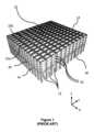
EP1037828B1(Autostore)は、コンテナのスタックが、フレーム構造内に配置されているシステムを説明している。このタイプのシステムは、添付の図面の図1から4において概略的に図示されている。ロボット積荷取扱デバイスは、スタックの最上面上のトラックのシステム上で、スタックのあちこちに制御可能に移動できる。EP 1037828 B1 (Autostore) describes a system in which a stack of containers is arranged within a frame structure. A system of this type is illustrated diagrammatically in Figures 1 to 4 of the accompanying drawings. A robotic load handling device can be controllably moved around the stack on a system of tracks on the top surface of the stack.
積荷取扱デバイスは、英国特許出願番号GB2520104A-Ocado Innovation Limited-に記載されており、各ロボット積荷ハンドラが1つの格子空間のみをカバーし、したがって積荷ハンドラのより高い密度が、及びしたがって所定サイズのシステムの高いスループットが可能となる。The load handling device is described in UK Patent Application No. GB2520104A - Ocado Innovation Limited - in which each robotic load handler covers only one grid space, thus allowing a higher density of load handlers and therefore a higher throughput for a system of a given size.
上述の既知のロボットピッキングシステムでは、ロボット積荷取扱デバイスは、格子を形成するトラックシステム上においてスタックの頂部の周囲を制御可能に移動される。所定の積荷取扱デバイスが、スタックからビンを持ち上げ、コンテナは、顧客注文を満たすために必要とされる在庫アイテムを含んで持ち上げられる。コンテナは、ピックステーションへ搬送され、そこで必要な在庫アイテムがビンから手作業で取り出され、配送コンテナ内に配置されてもよい。配送コンテナは、顧客注文の一部を構成しており、適時の発送に向けて手作業で充填される。ピックステーションにおいて、それらのアイテムはまた、例えば英国特許出願番号GB2524383B-Ocado Innovation Limitedに記載されているような、かかる作業に適した産業ロボットによってもピッキングされてもよい。In the known robotic picking systems mentioned above, a robotic load handling device is controllably moved around the top of the stack on a track system forming a grid. A given load handling device picks up a bin from the stack and a container is lifted containing the inventory items required to fulfill a customer order. The container is transported to a pick station where the required inventory items may be manually removed from the bin and placed in a shipping container. The shipping container forms part of the customer order and is manually filled for timely dispatch. At the pick station, the items may also be picked by an industrial robot suitable for such operations, for example as described in UK Patent Application No. GB2524383B - Ocado Innovation Limited.
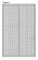
図1及び図2に示すように、ビン10として知られるスタック可能保管コンテナが、スタック12を形成するように互いの上に重ねられる。スタック12は、倉庫又は製造環境におけるフレームワーク14内に配置される。図1は、フレームワーク14の概略斜視図であり、図2は、フレームワーク14内に配置されたビン10の単一のスタック12を示す上から見た図である。各ビン10は、典型的には複数の製品又は在庫アイテムを保持し、ビン10内の在庫アイテムは、同一であってもよく、又は用途に応じてそれぞれ異なる製品タイプのものであってもよい。さらに、ビン10は、複数の異なる在庫アイテムを収容するように物理的に小区分されてもよい。As shown in Figures 1 and 2, stackable storage containers known as
フレームワーク14は、水平の部材18、20を支持する複数の直立部材16を備えている。直立の部材16によって支持されている複数の水平の格子構造を形成するために、平行な水平の部材18の第1のセットは、平行な水平の部材20の第2のセットに直角に配置されている。部材16、18、20は、典型的に、金属から製造されている。フレームワーク14は、ビン10のスタック12の水平移動に対してガードし、ビン10の垂直の移動を誘導するように、ビン10は、フレームワーク14の部材16、18、20の間で積み重ねられている。The
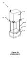
フレームワーク14の最上レベルは、スタック12の最上部にわたって格子パターンに配置されたレール22を含む。図3及び図4をさらに参照すると、レール22は、複数のロボット積荷取扱デバイス30を支持する。平行なレール22の第1のセット22aは、フレームワーク14の一番上に渡って、第1の方向(X)における積荷取扱デバイス30の移動を誘導し、平行なレール22の第2のセット22bは、第1のセット22aに対して直角に配置され、第1の方向に対して直角な第2の方向(Y)において、積荷取扱デバイス30の移動を誘導する。このようにして、レール22は、X-Y平面において2次元における積荷取扱デバイス30の動きを可能にし、その結果、積荷取扱デバイス30は、スタック12のうちの任意のものの上方のポジションへと移動できる。The top level of the
各積荷取扱デバイス30は、スタック12の上方で、フレームワーク14のレール22上をX方向及びY方向に移動するように配置された車両32を備える。車両32の正面にある一対の車輪34と、車両32の背面にある一対の車輪34とからなる、車輪の第1のセット34は、レール22の第1のセット22aのうちの2つの隣接するレールと係合するように配置されている。同様に、車両32の各側の一対の車輪36からなる車輪の第2のセット36は、レール22の第2のセット22bの2つの隣接するレールと係合するように配置される。車輪の各セット34、36は、車輪の第1のセット34又は車輪の第2のセット36のいずれかがレールのそれぞれのセット22a、22bとどの時点においても係合するように、持ち上げられ、下げられることができる。Each
車輪の第1のセット34が第1のレールのセット22aと係合し、車輪の第2のセット36がレール22から離れて持ち上げられたとき、車輪34は、積荷取扱デバイス30をX方向に移動させるために、車両32内に収容された駆動機構(図示せず)によって駆動されることができる。積荷取扱デバイス30をY方向に移動させるために、車輪の第1のセット34が、レール22から離れて持ち上げられ、車輪の第2のセット36が、レールの第2のセット22bと係合するように下げられる。次いで、駆動機構は、Y方向への移動を達成するように、車輪36の第2のセットを駆動させるために使用されてもよい。When the first set of
このようにすることで、1つ以上のロボット積荷取扱デバイス30が、集中制御ユーティリティ(図示せず)の制御下で図4に示されるようにフレームワーク14上でスタック12の頂部表面の周囲を移動することが可能となる。各ロボット積荷取扱デバイス30には、必要とされる製品にアクセスするためにスタック12から1つ以上のビン10を持ち上げるための持ち上げ手段38が設けられる。In this manner, one or more robotic
車両32の本体は、空洞部40を備え、空洞部40は、ビン10を保持することが可能なサイズのものである。持ち上げ手段38は、ウィンチ手段及びビングリッパアセンブリ39を備える。持ち上げ手段は、スタック12から車両32の本体内の空洞部40内へとビン10を持ち上げる。空洞部40において、ビン10が下のレールから完全に持ち上げられるとき、積荷取扱デバイスは、格子上の異なるロケーションへと横方向に移動できる。ターゲットロケーション、例えば、別のスタック、保管システム中のアクセスポイント、又は、コンベヤベルトに達すると、ビン10は、空洞部から下げられ、グリッパアセンブリ39から取り外されることができる。The body of the
このようにして、複数の製品が、どの時点においても格子及びスタックにおける複数のロケーションからアクセスされることができる。In this way, multiple products can be accessed from multiple locations in the grid and stack at any one time.
上記の説明は、例えば食料品に関連する保管システムを説明している。The above description describes a storage system relating to, for example, food products.
図4は、典型的な保管システムを示し、システムは、スタック12の上方の格子上で作動する複数の積荷取扱デバイス30を有する。Figure 4 shows a typical storage system having multiple
図1及び図4は、保管システム内のスタック12におけるビン10を示す。任意の所定の保管システム内に多数のビン10が存在してもよく、多数の異なるアイテムがスタック12中のビン10に保管されてもよいことが理解されよう。各ビン10は、単一のスタック12内に異なるカテゴリの在庫アイテムを収容することができる。FIGS. 1 and 4
上述の及び参照により本明細書に組み込まれる英国特許出願番号GB2517264A-Ocado Innovation Limitedにさらに記載されているあるシステムでは、保管システムは、顧客注文が中に収容された配送コンテナDTをさらに備えてもよく、又はピッキング待機中の在庫アイテムが中に収容されたビン10をさらに備えてもよい、一連のビン10を備える。これらの種々のビン10及びそれらの組み合わせは、保管システム内に収容され、上述のようにロボット積荷取扱デバイス30によりアクセスされてもよい。In one system, as described above and further described in UK Patent Application No. GB2517264A - Ocado Innovation Limited, which is incorporated herein by reference, the storage system comprises a series of
自動又は半自動の保管及び取り出しシステムは、食料品を対象とするシステムに限定されないことが理解されるであろう。例えば、本テクノロジーは、いくつかの可能な用途を挙げると、出荷、手荷物処理、車両駐車、屋内又は水耕温室及び農業、モジュール式建物、自己保管設備、荷役、輸送スイッチヤード、製造設備、パレット処理、小包仕分け、空港物流(ULD)、及び一般物流に適用できる。異なるタイプの保管及び取り出しシステムは、異なる技術的要件を有することが理解されるであろう。It will be appreciated that the automated or semi-automated storage and retrieval systems are not limited to systems directed to food products. For example, the technology can be applied to shipping, baggage handling, vehicle parking, indoor or hydroponic greenhouses and agriculture, modular buildings, self-storage facilities, cargo handling, transportation switch yards, manufacturing facilities, pallet handling, parcel sorting, airport logistics (ULD), and general logistics, to name a few possible applications. It will be appreciated that different types of storage and retrieval systems have different technical requirements.
これは、本発明が考案しているこの背景とは対照的である。This is in contrast to the background against which this invention is conceived.
本開示は、従来のシステムに対する効率的かつ経済的な代替を提供するためのシステム、方法、及びデバイスを説明する。例えば、本開示は、大きくてかさばるアイテムを保管し、取り出すために使用することができる。いくつかの規模では、すなわち、非常に大きなコンテナが利用される場合、立方体システムを動作させることは非実用的であるかもしれない。The present disclosure describes systems, methods, and devices for providing an efficient and economical alternative to conventional systems. For example, the present disclosure can be used to store and retrieve large and bulky items. At some scales, i.e., when very large containers are utilized, it may be impractical to operate a cube system.
本発明の態様は、添付の特許請求の範囲に記載されている。Aspects of the invention are set out in the accompanying claims.
システム
保管システムが提供され、保管システムは、格子システムに基づくトラックネットワークを備える少なくとも1つの保管フロアを備え、トラックネットワークは、第1の(x)方向に伸長するトラック部材の第1のセットと、第2の(y)方向に伸長するトラック部材の第2のセットとを備え、トラック部材の第2のセットは、実質的に水平な平面内でトラック部材の第1のセットに対して横方向に延び、トラックネットワークは、アクセス通路及び保管通路を備え、保管通路は、保管コンテナを受け入れるための1つ以上の保管ロケーションと、保管コンテナを持ち上げて輸送するためにトラックネットワーク上で動作する少なくとも1つの積荷取扱デバイスとを備える。保管ロケーションは、保管コンテナを支持するための支持手段を備えることができる。 System A storage system is provided, comprising at least one storage floor comprising a track network based on a grid system, the track network comprising a first set of track members extending in a first (x) direction and a second set of track members extending in a second (y) direction, the second set of track members extending transversely to the first set of track members in a substantially horizontal plane, the track network comprising an access aisle and a storage aisle, the storage aisle comprising one or more storage locations for receiving storage containers and at least one load handling device operative on the track network for lifting and transporting the storage containers. The storage locations may comprise support means for supporting the storage containers.
保管ロケーションは、保管フロア又はレベルの上に配置される。保管コンテナは、保管フロア又はレベル内の支持手段上に位置付けられている。支持手段は、1つ以上の架台、支持体又はブラケットを含むことができ、任意選択で、支持手段は、少なくとも2つの架台又は支持体又はブラケットを含むことができる。典型的には、保管コンテナは保管ロケーションに保管される。The storage location is located above a storage floor or level. The storage container is positioned on a support means within the storage floor or level. The support means may include one or more racks, supports or brackets, and optionally the support means may include at least two racks or supports or brackets. Typically, the storage container is stored in the storage location.
保管コンテナは、積荷取扱デバイス又はボットによってシステムの周りを移動する。積荷取扱デバイスは、半自動又は完全自動であってもよい。架台、ブラケット又は支持体は、積荷取扱デバイスがそれらの間を通過し、トラックのネットワーク又はトラックネットワーク上を移動することができるようなサイズ及び配置にされる。さらに、架台は、保管コンテナが架台によって支持されているときに、荷降ろしされた積荷取扱デバイスが保管コンテナの下を通過できるような高さである。The storage containers are moved around the system by load handling devices or bots. The load handling devices may be semi-automatic or fully automatic. The cradles, brackets or supports are sized and positioned such that the load handling devices can pass between them and move on the network of trucks or tracks. Additionally, the cradles are of a height such that the unloaded load handling devices can pass under the storage containers when the storage containers are supported by the cradles.
トラックネットワークは、典型的には架台のない多数のアクセス通路と、コンテナの保管のためのロケーションを提供する架台を備えた多数の保管通路とを備えて配置される。保管通路から離れて、さらなる保管ロケーションにアクセスするための多数の側部通路があってもよい。保管通路の側部通路は、1つ以上の保管ロケーションの深さである。典型的には、保管システムが保管密度に関して最適化されているとき、側部通路は、2から6個の保管ロケーションの深さである。高速でほぼ均一な取り出し時間に最適化された保管システムの場合、側部通路は1つの深さであってもよい。複数の保管通路は、保管通路の各端部に位置付けられたアクセス通路によって接続されてもよい。The track network is typically arranged with a number of access aisles without racks and a number of storage aisles with racks providing locations for storage of containers. There may be a number of side aisles off the storage aisles to access further storage locations. A side aisle of a storage aisle is one or more storage locations deep. Typically, when the storage system is optimized for storage density, the side aisles are two to six storage locations deep. For storage systems optimized for high speed and approximately uniform retrieval times, the side aisles may be one deep. Multiple storage aisles may be connected by access aisles located at each end of the storage aisle.
トラックネットワーク、したがって保管ロケーションは、利用可能な空間を効率的に利用し、典型的にはシステム又は設備の保管容量を最大化するために、格子システム上に配置される。各格子ユニットは、「予約可能ロケーション」と考えられてもよい。予約可能ロケーションは、単一の格子ユニットであってもよく、又は予約可能ロケーションは、多数の隣接する格子ユニット、例えば、トラック又は経路の長さであってもよい。いくつかの例では、予約可能なトラックの長さは単一のユニットであってもよく、他の例では、同じユニットトラックのいくつかは、互いに独立して予約可能であってもよい。予約可能ロケーションの予約は、開始時間と終了時間とを有してもよい。このように、格子ユニットが予約されているか否かは時間とともに変化する。予約可能ロケーションは、特定の保管コンテナ及び/又は積荷取扱デバイスのために予約されてもよい。システム内のあらゆるロケーションが予約可能であってもよい。時間の経過とともに、各予約可能ロケーションは、同じ若しくは異なる積荷取扱デバイス及び/又は保管コンテナに対するものであってもよい、いくつかの重複しない予約を有してもよい。予約可能ロケーションの予約は、予約可能ロケーションテーブルに保持されてもよい。積荷取扱デバイスナビゲーションシステム及びコントローラは、可変長の予約可能ロケーションをサポートしてもよいことが理解されるであろう。各可変長の予約可能ロケーションにおいて、積荷取扱デバイスがその移動方向をトラックネットワーク上の直交方向に変更することができる最大1つのポジションが存在してもよい。このようにして、格子システムのロケーションは、以下でより詳細に説明する制御設備によって管理することができる。The truck network, and therefore the storage locations, are arranged on a grid system to efficiently utilize the available space and typically maximize the storage capacity of the system or facility. Each grid unit may be considered a "reservable location." A reservable location may be a single grid unit, or a reservable location may be a number of adjacent grid units, e.g., a length of a truck or a route. In some examples, a reservable truck length may be a single unit, and in other examples, several of the same unit trucks may be reservable independently of each other. A reservation of a reservable location may have a start time and an end time. In this way, whether a grid unit is reserved or not changes over time. A reservable location may be reserved for a particular storage container and/or load handling device. Every location in the system may be reservable. Over time, each reservable location may have several non-overlapping reservations, which may be for the same or different load handling devices and/or storage containers. Reservations of reservable locations may be maintained in a reservable location table. It will be appreciated that the load handling device navigation system and controller may support reservable locations of variable length. At each variable length reservable location, there may be up to one position where the load handling device can change its direction of movement to an orthogonal direction on the track network. In this manner, the locations of the grid system may be managed by a control facility, which is described in more detail below.
典型的には、トラックは、トラフ、レール、案内路、又は積荷取扱デバイスの車輪を受け入れるか又はそれと係合するための任意の他の適切な構造を備える。トラフ、レール又は案内路は、各トラック経路に対して対になっていてもよい。トラックは、積荷取扱デバイスのための経路を提供する。いくつかの格子空間は、建物及びフロアを通って伸長する支柱等の建物構造の特徴を収容するためのトラックがなくてもよいことが理解されるであろう。トラックネットワークは、任意の数の第1及び第2の部材から構成されてもよい。第1及び第2のトラック部材は、格子パターンに従って、実質的に直交して配置される。フロアは実質的に平坦かつ水平であり、トラックは実質的に水平面に配置される。Typically, the tracks comprise troughs, rails, guideways, or any other suitable structure for receiving or engaging the wheels of the load handling device. The troughs, rails, or guideways may be paired for each track path. The tracks provide a path for the load handling device. It will be appreciated that some grid spaces may be without tracks to accommodate building structural features such as columns extending through the building and floors. The track network may be comprised of any number of first and second members. The first and second track members are arranged substantially orthogonally according to a grid pattern. The floor is substantially flat and level, and the tracks are arranged in a substantially horizontal plane.
システム内の各ロケーションは、単一の格子ユニットを備えてもよく、又はロケーションは、整数個の格子ユニットを備えてもよい。トラックは、単一の格子ユニット幅であってもよい。典型的には、各格子ユニットは、x方向のトラックと、y方向のトラックとを含むことができる。典型的には、保管ロケーション及びシステムの他の特徴は、単一の格子ユニットを備えてもよい。Each location in the system may comprise a single grid unit, or the locations may comprise an integer number of grid units. The tracks may be a single grid unit wide. Typically, each grid unit may include a track in the x direction and a track in the y direction. Typically, the storage locations and other features of the system may comprise a single grid unit.
積荷取扱デバイスによって輸送されるとき、保管コンテナは、積荷取扱デバイスの上面に位置付けられた支持パッドによって支持される。支持パッドは、積荷取扱デバイスの経路に沿って配置された架台から離れて保管コンテナを持ち上げることができるように、積荷取扱デバイスによって昇降させることができ、その結果、架台は保管コンテナの移動を妨げない。典型的には、積荷取扱デバイスは、安定性のために支持パッドを下げた状態で移動する。典型的には、積荷取扱デバイスが目的ロケーション(保管ロケーションなど)に隣接するロケーションに到着するとき、積荷取扱デバイスは支持パッドを上昇させる。次に、積荷取扱デバイスは、保管コンテナを配置するポジションに移動する。積荷取扱デバイスが目的ロケーションの架台間の所定ポジションにあるとき、支持パッドは下降され、保管コンテナは各端部で一対の架台によって支持される。その後、積荷取扱デバイスは、別の積荷取扱作業を実行するために、保管ロケーションからトラックネットワークに沿って移動し続けることができる。典型的には、積荷取扱デバイスは、アクセス通路を使用することによって、同じフロアの保管通路間を移動する。When transported by the load handling device, the storage container is supported by a support pad positioned on the upper surface of the load handling device. The support pad can be raised and lowered by the load handling device so that the storage container can be lifted away from the cradles located along the path of the load handling device, so that the cradles do not impede the movement of the storage container. Typically, the load handling device moves with the support pad lowered for stability. Typically, when the load handling device arrives at a location adjacent to a destination location (such as a storage location), the load handling device raises the support pad. The load handling device then moves to a position to place the storage container. When the load handling device is in position between the cradles of the destination location, the support pad is lowered and the storage container is supported by a pair of cradles at each end. The load handling device can then continue to move along the track network from the storage location to perform another load handling operation. Typically, the load handling device moves between storage aisles on the same floor by using an access aisle.
トラックネットワークは、保管コンテナを支持するための支持手段を備える1つ以上の一時保管ロケーションを備えることができる。トラックネットワークは、充電ベイ、通過レーン、サイディング、退避(lay-by)、及び/又は通過ポイントのうちの1つ以上をさらに備えてもよい。The track network may comprise one or more temporary storage locations comprising support means for supporting storage containers. The track network may further comprise one or more of charging bays, passing lanes, sidings, lay-bys, and/or passing points.
フロア又はトラックネットワークのレイアウトは、典型的には、システムの効率的な動作のための追加の特徴を備える。例えば、アクセス通路は2対のトラック幅であってもよい。内側の対のトラック(例えば、保管通路に最も近い)は、積荷取扱デバイスの通行のための概念的な主経路又はハイウェイを提供する。外側の対のトラック(例えば、保管通路から最も遠い)は、ネットワークの他の特徴のためのロケーションを提供してもよい。The layout of the floor or track network typically includes additional features for efficient operation of the system. For example, an access aisle may be two pairs of tracks wide. The inner pair of tracks (e.g., closest to the storage aisle) provides a conceptual main path or highway for the passage of load handling devices. The outer pair of tracks (e.g., furthest from the storage aisle) may provide locations for other features of the network.
例えば、退避は、故障若しくは損傷した積荷取扱デバイスの自動回復のためのもの、又はオペレータが積荷取扱デバイスにアクセスするためのもの、又は故障した積荷取扱デバイスを現場での修理若しくはメンテナンスエリアへの除去を待って配置するためのものであってもよい。通過ポイントは、同じ内側トラック経路上を反対方向に移動する積荷取扱デバイスが通過することを可能にしてもよい。さらに、トラックネットワークは、システムが動作するための他の補助機能のためのロケーションを備えてもよい。For example, evacuation may be for automatic recovery of a failed or damaged load handling device, or for an operator to access a load handling device, or for placing a failed load handling device awaiting removal to an on-site repair or maintenance area. Passage points may allow load handling devices traveling in the opposite direction on the same interior track path to pass through. Additionally, the track network may include locations for other auxiliary functions for the system to operate.
積荷取扱デバイスの充電ロケーション又は充電ポイントは、トラック間に配置された誘導充電パッドを含むことができ、この誘導充電パッドは、積荷取扱デバイスの下側の相互に関連する充電パッドを介してエネルギーを積荷取扱デバイスに誘導的に伝達する。典型的には、積荷取扱デバイスが、ある期間を費やす傾向がある場所に、積荷取扱デバイスの充電ロケーションは位置付けられてもよい。例えば、充電ロケーションは、積荷取扱デバイスが次に利用可能なリフト車が別のレベルに移動するのを待つ間に積荷取扱デバイスを充電するための、リフトに隣接する待機ロケーション、コンテナ受取りステーションのロケーション、コンテナ発送ステーションのロケーション、受取りステーションポジションが利用可能になるまで積荷取扱デバイスが待機するコンテナ誘導ステーションに対する待ち行列ロケーション、発送ステーションポジションが利用可能になるまで積荷取扱デバイスが待機するコンテナ発送ステーションに対する待ち行列ロケーション、又はアクセス通路に沿った1つ以上のロケーションも含むことができる。各保管フロアに少なくとも1つの充電ロケーションがあってもよいことが理解されるであろう。The charging locations or charging points for the load handling devices may include inductive charging pads located between the tracks that inductively transfer energy to the load handling devices via the interrelated charging pads on the underside of the load handling devices. Typically, the charging locations for the load handling devices may be located where the load handling devices tend to spend a period of time. For example, the charging locations may include a waiting location adjacent to a lift to charge the load handling device while the load handling device waits for the next available lift car to move to another level, a location at a container receiving station, a location at a container shipping station, a queue location for a container guide station where the load handling device waits until a receiving station position is available, a queue location for a container shipping station where the load handling device waits until a shipping station position is available, or even one or more locations along an access corridor. It will be understood that there may be at least one charging location on each storage floor.
隣接するトラックは、保管コンテナが積み込まれた2つの積荷取扱デバイスが、適切な公差のための十分な空間を有して隣接するトラック上を通過し、衝突を回避することを可能にするようなサイズであってもよい。Adjacent trucks may be sized to allow two load handling devices loaded with storage containers to pass over adjacent trucks with enough space for proper tolerances to avoid collisions.
一時的な保管ロケーションは、側部通路内のより深い場所にある保管コンテナにアクセスするために、側部通路から一時的に取り出された保管コンテナのために使用されてもよい。使用する際、例えば、いくつかの保管ロケーションの深さである通路内に位置付けられ保管コンテナは、アクセス通路からいくつかの格子ユニットだけ離れて位置付けられた保管コンテナにアクセスするために、一時的な保管ロケーションに移動されてもよい。The temporary storage location may be used for storage containers that are temporarily removed from a side aisle to access storage containers deeper in the side aisle. In use, for example, a storage container located in an aisle that is several storage locations deep may be moved to the temporary storage location to access a storage container located several grid units away from the access aisle.
積荷取扱デバイスが保管コンテナを運搬している場合、これらの一時的な保管ロケーションは、積荷取扱デバイスの積荷パッドが架台との衝突を回避するために上昇状態にあるときにのみアクセスされてもよい。典型的には、一時的な保管ロケーションは、トラフィックを通る積荷取扱デバイスが予想されるロケーションでは使用されない。If the load handling device is carrying storage containers, these temporary storage locations may only be accessed when the load pad of the load handling device is in a raised position to avoid collision with the pedestal. Typically, temporary storage locations are not used in locations where the load handling device is expected to be passing through traffic.
温度及び湿度制御であってもよい、物理的及び環境的に制御された保管条件を提供するように特別に構成された特定の通路があってもよい。There may be specific aisles specially configured to provide physically and environmentally controlled storage conditions, which may be temperature and humidity controlled.
特定の気体組成を有する特定の通路、例えば、火災リスク低減のための低酸素及び高窒素雰囲気が存在してもよい。保管設備のフロア全体は、火災リスク低減のために、低酸素及び高窒素雰囲気で動作してもよい。保管設備全体は、火災リスク低減のために、低酸素及び高窒素雰囲気で動作してもよい。There may be specific corridors with specific gas compositions, e.g. low oxygen and high nitrogen atmospheres for fire risk reduction. An entire floor of the storage facility may operate with low oxygen and high nitrogen atmospheres for fire risk reduction. The entire storage facility may operate with low oxygen and high nitrogen atmospheres for fire risk reduction.
通路は、1つ以上のチャンバ又はギャラリーに細分されてもよく、各チャンバは、温度及び湿度制御であってもよい、異なる、物理的及び環境的に制御された保管条件を提供するように構成される。The aisle may be subdivided into one or more chambers or galleries, each configured to provide different physically and environmentally controlled storage conditions, which may be temperature and humidity controlled.
フロアは、仕切り手段によってチャンバに分割されてもよく、仕切り手段は、積荷取扱デバイスが通過することができる開口部又はハッチを有する。仕切り手段は、防火手段を備えてもよく、及び/又は仕切り手段は、システム内のユーザアクセスとロボットアクセスとの間の分離を提供する。The floor may be divided into chambers by a partition means having openings or hatches through which load handling devices can pass. The partition means may be provided with fire protection means and/or the partition means provides separation between user access and robot access within the system.
仕切り手段は、仕切り壁を含むことができる。保管通路は、例えば、チャンバ又はギャラリーに細分化されてもよい。仕切り壁は、環境制御ドアを備えてもよい。これは、各ギャラリー又はチャンバが、例えば、それ自体の固有の目標周囲空気温度、固有の目標周囲空気湿度を有することを可能にしてもよい。The partitioning means may include partition walls. The storage aisle may be subdivided, for example, into chambers or galleries. The partition walls may comprise environmentally controlled doors. This may allow each gallery or chamber to have, for example, its own specific target ambient air temperature, its own specific target ambient air humidity.
システムは、炎検出システムをさらに備えてもよい。システムは、例えばスプリンクラーシステムを含む火災抑制システムをさらに備えてもよい。システムは、煙検出システムをさらに備えてもよい。システムは、熱検出システムをさらに備えてもよい。火災安全システムのそれぞれは、制御設備へのネットワーク接続を含むことができる。仕切り壁は、高密度の保管エリア内に、火災を封じ込める及び/又は火災の拡散を抑制する機会を提供することができる。The system may further include a flame detection system. The system may further include a fire suppression system including, for example, a sprinkler system. The system may further include a smoke detection system. The system may further include a heat detection system. Each of the fire safety systems may include a network connection to a control facility. The partition walls may provide an opportunity to contain and/or limit the spread of fire in high density storage areas.
保管システムは、2つ以上の垂直に配置されたフロアをさらに備えることができ、フロアは、フロア間で積荷取扱デバイスを移送するためにアクセス通路からアクセス可能な1つ以上のリフトによって相互接続され、フロアは、少なくとも1つの保管フロアと、任意選択で、リフト間で移送するための1つ以上のスカイロビーフロアとを備える。The storage system may further comprise two or more vertically arranged floors, the floors interconnected by one or more lifts accessible from an access aisle for transporting load handling devices between the floors, the floors comprising at least one storage floor and, optionally, one or more sky lobby floors for transport between the lifts.
保管システムは、2フロア以上をカバーするように拡張されてもよい。例えば、システムは、建物内のいくつかのフロアを占有してもよい。フロア又はレベル間の連続性を達成するために、積荷取扱デバイスは、特別に設計されたリフト内の異なるレベル間を移動することができる。リフトは、積荷取扱デバイスの支持パッド上に保管コンテナを載せて、又は載せずに、積荷取扱デバイスを輸送することができる。The storage system may be expanded to cover more than one floor. For example, the system may occupy several floors in a building. To achieve continuity between floors or levels, the load handling devices can move between the different levels in specially designed lifts. The lifts can transport the load handling devices with or without storage containers on the load handling device's support pads.
複数階システムでは、異なるフロアが異なるサービスレベルのために予約されてもよい。保管システム出力ステーションへの最短の通過時間を有するフロアは、最速のアクセス時間を必要とするコンテナの保管のために予約されてもよい。一方、保管システム出力ステーションへの最長の通過時間を有するフロアは、最速のアクセス時間を必要としない、又は最速のアクセス時間に対して割増料金を支払わないコンテナの保管のために予約されてもよい。In a multi-floor system, different floors may be reserved for different service levels. The floor with the shortest transit time to the storage system output station may be reserved for storage of containers that require the fastest access time, while the floor with the longest transit time to the storage system output station may be reserved for storage of containers that do not require the fastest access time or do not pay a premium for the fastest access time.
いくつかの通路は、単一の保管ロケーションの深さの側部通路で構築されてもよい。これらの通路は、最速のアクセス時間を必要とするコンテナを保管するために予約されてもよい。Some aisles may be constructed with side aisles the depth of a single storage location. These aisles may be reserved for storing containers that require the fastest access times.
各階又はフロアは、1つ以上のリフトによってサービス提供されてもよい。典型的には、リフトは双方向リフトであってもよく、すなわち上下に移動することができる。リフトは、通路にアクセスするために直接的又は間接的に位置付けられてもよい。フロア又はリフト車は、積荷取扱デバイスが保管フロアからリフトに直接移動することを可能にするトラックを有することができる。リフト車は、保管コンテナが積載された1つの積荷取扱デバイスを収容するようにサイズ決めされてもよく、又はリフト車は、保管コンテナを輸送する2つ以上の積荷取扱デバイスを収容するようにサイズ決めされてもよい。Each floor or story may be serviced by one or more lifts. Typically the lifts may be bi-directional, i.e., capable of moving up and down. The lifts may be positioned directly or indirectly to access the aisles. The floors or lift cars may have tracks that allow the load handling devices to move directly from the storage floor to the lifts. The lift cars may be sized to accommodate one load handling device loaded with storage containers, or the lift cars may be sized to accommodate two or more load handling devices transporting storage containers.
典型的には、リフトが故障した場合に弾性を提供するために、各フロアへのアクセスを有する少なくとも2つの双方向リフトがある。Typically there are at least two bi-directional lifts with access to each floor to provide resiliency in case a lift fails.
いくつかの配置では、リフトは、より高いリフトスループットを生成するために、積み重ねられたリフト車を備え、隣接するフロアに同時にサービスを提供し、2つの積荷取扱デバイスを搬送することが可能な2階建てであってもよい。2階建てリフト車について、2つの積荷取扱デバイスは、リフトの移動中に異なるレベルに集められるか又は配置されてもよく、より高い平均リフトスループットをもたらす。In some arrangements, the lift may be two-storey with stacked lift cars, capable of servicing adjacent floors simultaneously and carrying two load handling devices, to generate higher lift throughput. For a two-storey lift car, the two load handling devices may be clustered or positioned at different levels during the lift's travel, resulting in a higher average lift throughput.
複数階システムのいくつかのレベル又はフロアは、スカイロビーを含むことができ、積荷取扱デバイスは、リフトシステム間のトラック経路上を移動することができる。スカイロビーのないシステムでは、リフトは、各保管フロアで停止することができる。いくつかのシステムでは、リフトは、選択されたフロア又はレベルで停止することができる。例えば、いくつかのリフトは、システム内の下のフロアのみにサービスを提供し、他のリフトは上のフロアにサービスを提供する。又は、いくつかのリフトは、特定の目的地のために予約されてもよい。典型的には、スカイロビー配置は、高層ビルの構造上の制限のために単一リフトシステムが実現可能でない高層ビルにおいて見出されてもよい。1つ以上のスカイロビーを有するシステムについて、リフトは、隣接するフロアのブロックへのアクセスを提供することができる。いくつかのシステムでは、建物内の同じレベルへのアクセスを提供する少なくとも2つのスカイロビーフロアがあってもよく、特定のレベルにおけるリフト車の入口/出口での予約可能なトラックロケーションをブロックする積荷取扱デバイスの故障の場合に、システムに復元力を提供することができる。Some levels or floors of a multi-floor system may include sky lobbies, and load handling devices may travel on truck paths between lift systems. In systems without sky lobbies, lifts may stop at each storage floor. In some systems, lifts may stop at selected floors or levels. For example, some lifts may only serve lower floors in the system, while others serve upper floors. Or, some lifts may be reserved for specific destinations. Typically, sky lobby arrangements may be found in high-rise buildings where a single lift system is not feasible due to architectural limitations of high-rise buildings. For systems with one or more sky lobbies, lifts may provide access to blocks of adjacent floors. In some systems, there may be at least two sky lobby floors providing access to the same level in the building, providing resilience to the system in case of a failure of a load handling device that blocks a reservable truck location at the entrance/exit of a lift car at a particular level.
多くのレベル又はフロアを有する非常に高い保管設備について、最下フロアと最上フロアとの間の垂直経路は、いくつかのリフト又はリフトシステムを介した通過を必要とする場合がある。1つのリフトシステムから別のリフトシステムへの移動は、スカイロビーフロアの移動通路を介して行われてもよい。スカイロビーフロアは、リフトシステム間で移動するためのフロアと同様に、保管フロアであってもよい。又は、スカイロビーフロアは、単に移動フロアであってもよい。For very tall storage facilities with many levels or floors, the vertical path between the lowest and the top floor may require passage through several lifts or lift systems. Transfer from one lift system to another may occur through a transfer passage on a sky lobby floor. The sky lobby floor may be a storage floor as well as a floor for transferring between lift systems. Or, the sky lobby floor may simply be a transfer floor.
保管システムのレベル又はフロアは、保管システムが位置付けられる建物のフロアに必ずしも対応する必要はないことが理解されるであろう。例えば、いくつかの保管システムフロアが、単一階の倉庫タイプの建物内に位置付けられてもよく、保管システムフロアを作成するために空間内に構造物を有する。It will be appreciated that the levels or floors of a storage system do not necessarily correspond to floors of the building in which the storage system is located. For example, several storage system floors may be located within a single floor warehouse type building, with structures within the space to create the storage system floors.
保管システムはさらに、制御設備、環境制御設備手段、安全システム、データ収集手段、データ通信手段、及び通信システムのうちの1つ以上を備えてもよい。The storage system may further include one or more of a control facility, an environmental control facility means, a safety system, a data collection means, a data communication means, and a communication system.
環境制御設備は、地球規模の環境制御システム、又は保管フロア若しくはフロアの一部のための環境制御システムを備えてもよい。制御システムは、空気の温度及び/若しくは湿度、並びに/又は気体組成、例えば空気の窒素含有量を制御することができる。The environmental control facility may comprise a global environmental control system or an environmental control system for a storage floor or part of a floor. The control system may control the temperature and/or humidity of the air and/or the gas composition, e.g. the nitrogen content of the air.
保管設備は、1つ以上のフロア上に1つ以上のメンテナンスエリアを備えることができる。メンテナンスエリアは、オペレータによってアクセス可能であってもよい。The storage facility may include one or more maintenance areas on one or more floors. The maintenance areas may be accessible by the operator.
メンテナンスエリアは、仕切り又はバルクヘッド壁の間の空間に配置されてもよい。そのような空間は、サービスフィード、例えば、通信、電力、照明、環境感知、ビデオカメラ、火災検出、及び火災抑制のためのケーブル及びインフラストラクチャのためのルートを提供してもよい。仕切り手段は、技術者が作業するための又は避難のための安全エリアを提供するための一時的な障壁を含むことができる。Maintenance areas may be located in spaces between partition or bulkhead walls. Such spaces may provide routes for cables and infrastructure for service feeds, such as communications, power, lighting, environmental sensing, video cameras, fire detection, and fire suppression. Partitioning means may include temporary barriers to provide safe areas for technicians to work or for evacuation.
保管フロア又は通路は、メンテナンスエリアと交互に配置されてもよい。他の配置では、通路は、並んで又は背中合わせに配置されてもよく、特に、例えば、生育トレイを搬送することなく移動するときに、トラックネットワーク上で(アクセス通路を介するのではなく)通路間を直接移動するための積荷取扱デバイスを提供する。Storage floors or aisles may be arranged in alternating fashion with maintenance areas. In other arrangements, aisles may be arranged side-by-side or back-to-back, providing load handling devices for moving directly between aisles on a track network (rather than via an access aisle), particularly when moving without carrying, for example, growing trays.
メンテナンスエリアは、例えば天井から吊り下げられたケーブル通路を含むことができる。ケーブル通路は、実際には、生育フロアがメンテナンスレベルと交互に配置されない場合に使用されてもよい。The maintenance area may include, for example, a cable passage suspended from the ceiling. A cable passage may in fact be used when the growing floor is not interleaved with the maintenance level.
保管システムは、1つ以上のワークステーションをさらに備えることができ、任意選択で、各ワークステーションは、保管コンテナの識別タグ又はラベルを読み取るためのRFIDリーダ、スキャナ、又はカメラを備える。The storage system may further include one or more workstations, optionally each workstation including an RFID reader, scanner, or camera for reading identification tags or labels on the storage containers.
1つ以上のワークステーションは、オペレータに好適であってもよく、又は1つ以上のワークステーションは、自動化又は半自動化されてもよい。このようにして、保管システムは、グッズツーマン(Goods-to-man)システムであってもよい。保管コンテナは、積荷取扱デバイス上の作業ステーションへ、又は作業ステーションを通って輸送されてもよい。保管コンテナは、ワークステーションにある間、積荷取扱デバイス上に留まってもよく、又は、保管コンテナは、積荷取扱デバイスによって、ワークステーションにある1対又は一組の架台上に配置されてもよい。One or more of the workstations may be suitable for an operator, or one or more of the workstations may be automated or semi-automated. In this manner, the storage system may be a goods-to-man system. The storage containers may be transported to or through the workstations on the load handling device. The storage containers may remain on the load handling device while at the workstation, or the storage containers may be placed by the load handling device on a pair or set of cradles at the workstation.
ワークステーションは、保管コンテナ上でプロセスを実行するためのものである。システム内のワークステーションは、コンテナ導入ワークステーション、コンテナ発送ワークステーション、コンテナから物品又はアイテムをピッキングし、これらを別のコンテナに移送するための、又はアイテムを配送コンテナに移送するためのピッキングワークステーション、空の保管コンテナをコンテナ導入に戻すためのワークステーションのうちの1つ以上を含むことができる。The workstations are for performing processes on the storage containers. The workstations in the system may include one or more of a container introduction workstation, a container dispatch workstation, a picking workstation for picking goods or items from a container and transferring them to another container or transferring items to a shipping container, and a workstation for returning empty storage containers to the container introduction.
1つ以上の特定のワークステーションが単一のワークステーションに組み合わされてもよい。例えば、組み合わされたワークステーションは、異なるタスク又は機能を同じワークステーションで実行することができる、組み合わされた導入及び発送ワークステーションを含むことができる。One or more of the particular workstations may be combined into a single workstation. For example, a combined workstation may include a combined installation and dispatch workstation, where different tasks or functions may be performed on the same workstation.
各ワークステーションは、保管コンテナを処理する前に、保管コンテナの識別タグ又はラベルを読み取る能力を有することができる。このようにして、コントローラは、各段階で保管コンテナが正しく取り扱われていることを確認することができ、保管コンテナがどの段階でも正しく処理されていない場合、是正措置をとることができる。Each workstation may have the capability to read the identification tag or label of a storage container before processing the storage container. In this way, the controller can verify that the storage container is being handled correctly at each stage and can take corrective action if the storage container is not being processed correctly at any stage.
保管システム内では、異なるタイプのワークステーションが、単一のフロア上又はフロアの特定のエリア内に位置付けられてもよく、又はワークステーションが、生育フロア及び/又はスカイロビーフロア上に分散されてもよい。Within a storage system, different types of workstations may be located on a single floor or within specific areas of a floor, or the workstations may be distributed across the growing floor and/or sky lobby floor.
保管システムは、補助機能を備えることができる。The storage system can be equipped with auxiliary functions.
保管システムは、補助空間及び補助機能をさらに備えてもよいことが理解されるであろう。例えば、保管システムは、マシンツーパーソン(machine-to-person)ワークステーション、及び積荷取扱デバイスサービス及びメンテナンスステーションであってもよい。It will be appreciated that the storage system may further include auxiliary spaces and functions. For example, the storage system may be a machine-to-person workstation, and a load handling device service and maintenance station.
保管コンテナは、標準的な出荷コンテナを含んでもよい。あるいは、保管コンテナは、アイテムが置かれる大面積トレイを含んでもよい。保管コンテナは、固有の識別タグ又はラベルを含んでもよい。The storage container may include a standard shipping container. Alternatively, the storage container may include a large area tray into which the items are placed. The storage container may include a unique identification tag or label.
各保管コンテナは、固有の識別タグ又はラベルを提供するスキャナ又はカメラで読み取ることができるバーコード又はQRコード(登録商標)などのRFIDタグ又はマーカを有することができる。相互に関連して、積荷取扱デバイス又はシステムの積荷取扱デバイスは、生育トレイのラグ又はラベルを読み取ることができるRFIDリーダ又はスキャナ又はカメラを有することができる。同様に、生育トレイを処理するために使用されるワークステーションは、生育トレイのラグ又はラベルを読み取ることが可能な相互に関連するRFIDリーダ又はスキャナ又はカメラを有することができる。したがって、積荷取扱デバイスは、生育トレイを架台から取り上げる動作中に、生育トレイのタグ又はラベルを読み取る能力を有する。同様に、各生育トレイ処理ワークステーションは、生育トレイのタグ又はラベルを読み取る能力を有する。各生育トレイ処理ワークステーションは、生育トレイを処理する前に生育トレイのタグ又はラベルを読み取ってもよい。このようにして、コントローラは、正しい生育トレイが各段階で取り扱われていることを確認することができ、それが任意の段階で正しい生育トレイでない場合、必要に応じて、修正措置を講じてもよい。有利なことに、システムは、制御の完全性の信頼性を高めることができ、監査記録を作成することを可能にすることができる。Each storage container may have an RFID tag or marker, such as a barcode or QR code, that can be read by a scanner or camera providing a unique identification tag or label. In relation to each other, the load handling device or the load handling device of the system may have an RFID reader or scanner or camera that can read the lugs or labels of the growth trays. Similarly, the workstations used to process the growth trays may have an RFID reader or scanner or camera that can read the lugs or labels of the growth trays. Thus, the load handling device has the ability to read the tag or label of the growth tray during the operation of picking the growth tray from the cradle. Similarly, each growth tray processing workstation has the ability to read the tag or label of the growth tray. Each growth tray processing workstation may read the tag or label of the growth tray before processing the growth tray. In this way, the controller can verify that the correct growth tray is being handled at each stage and may take corrective action, if necessary, if it is not the correct growth tray at any stage. Advantageously, the system may increase confidence in the integrity of the control and allow an audit trail to be created.
積荷取扱デバイス
保管システム内で動作するための積荷取扱デバイスが提供される。保管システムのフロアは、格子システムに基づくトラックのネットワーク又はトラックネットワークを備えることができ、トラックは、第1の(x)方向に伸長するトラック部材の第1のセットと、第2の(y)方向に伸長するトラック部材の第2のセットとを備え、トラック部材の第2のセットは、実質的に水平な平面内でトラック部材の第1のセットに対して横方向に延び、積荷取扱デバイスは、第1の方向でトラック部材のセットと係合するための車輪の第1のセット、及び第2の方向でトラック部材のセットと係合するための車輪の第2のセットと、ここで、積荷取扱デバイスは、トラックネットワーク上の任意のロケーションまで第1又は第2の方向に駆動可能であり、保管コンテナを運ぶための支持パッドとを備えることができる。 Load Handling Device A load handling device for operating within a storage system is provided, the floor of the storage system may comprise a network of tracks based on a lattice system or a track network, the tracks comprising a first set of track members extending in a first (x) direction and a second set of track members extending in a second (y) direction, the second set of track members extending transversely to the first set of track members in a substantially horizontal plane, the load handling device may comprise a first set of wheels for engaging the set of track members in the first direction and a second set of wheels for engaging the set of track members in the second direction, wherein the load handling device is drivable in the first or second direction to any location on the track network and may comprise a support pad for carrying a storage container.
支持パッドは、垂直(z)方向に上昇及び/又は下降されてもよい。The support pad may be raised and/or lowered in the vertical (z) direction.
積荷取扱デバイスは、ボット、自動車両又は半自動車両としても知られている。Load handling devices are also known as bots, autonomous vehicles or semi-autonomous vehicles.
このようにして、積荷取扱デバイスは、保管コンテナを持ち上げ、トラックのネットワークに沿って保管コンテナを保管ロケーション又はワークステーションなどの保管システム内の任意のロケーションに輸送するために使用されてもよい。ボット又は積荷取扱デバイスは、x方向トラック及びy方向トラックに沿って順方向及び逆方向に移動することが可能であってもよい。In this manner, the load handling device may be used to lift the storage container and transport it along the network of tracks to any location within the storage system, such as a storage location or a workstation. The bot or load handling device may be capable of moving forward and backward along the x- and y-tracks.
典型的には、保管コンテナは、積荷取扱デバイスによって架台などの支持手段上に配置することができる。保管コンテナを運搬する積荷取扱デバイスが所定ポジションにあるとき、支持パッドは、架台が保管コンテナを支持するように下降される。その後、積荷取扱デバイスは、トラックに沿ってそのロケーションから離れて(保管コンテナを搬送し続けることなく)、保管コンテナの下に移動し、その後の持ち上げ及び/又は輸送タスクに進むことができる。Typically, a storage container can be placed on a support means, such as a cradle, by a load handling device. When the load handling device carrying the storage container is in position, the support pad is lowered so that the cradle supports the storage container. The load handling device can then move away from its location along the track (without continuing to transport the storage container) and underneath the storage container to proceed with subsequent lifting and/or transport tasks.
支持パッドが下降ポジションにある状態で、保管又は他のポジションから保管コンテナを持ち上げるために、積荷取扱デバイスは、それ自体を保管コンテナの下に位置付け、積荷取扱デバイスが保管コンテナを支持し、保管コンテナを代替ロケーションに輸送してもよいように、支持パッドを上昇させる。To lift a storage container from a storage or other position with the support pad in the lowered position, the load handling device positions itself under the storage container and raises the support pad so that the load handling device supports the storage container and may transport the storage container to an alternative location.
支持パッド又は垂直リフト機構は、電気機械機構を備えてもよい。垂直リフト機構は、電気油圧発生機と、1つ以上の油圧ラムとを備えてもよい。故障及び漏出の場合に、保護囲いは、油圧流体が保管システムを汚染することを防止するために使用されてもよい。電気油圧発生器及びラム構成要素は、市販の構成要素であってもよい。The support pad or vertical lift mechanism may comprise an electro-mechanical mechanism. The vertical lift mechanism may comprise an electro-hydraulic generator and one or more hydraulic rams. In the event of failure or leakage, a protective enclosure may be used to prevent hydraulic fluid from contaminating the storage system. The electro-hydraulic generator and ram components may be commercially available components.
車輪の第1のセット及び/又は車輪の第2のセットは、各側に2つ以上の車輪を備えてもよい。積荷取扱デバイスは、1つ以上の車輪のためのサスペンション手段を備えてもよい。The first set of wheels and/or the second set of wheels may comprise two or more wheels on each side. The load handling device may comprise suspension means for one or more of the wheels.
保管設備のフロアは、トラックが実質的に水平面内にあるように実質的に平坦であってもよいが、フロアが完全に平坦であることを確実にすることは、費用効果が高くないかもしれないことが理解されるであろう。いずれにしても、フロアは、レベルにおいて段差変化を有しているかもしれず、又は平坦でないかもしれない。トラック経路は、制御設備と相互作用する積荷取扱デバイスのナビゲーション手段によって規定されてもよく、又はトラック経路は、本明細書の他の箇所に記載されるように、溝又はレールによって規定されてもよい。The floor of the storage facility may be substantially flat such that the tracks are in a substantially horizontal plane, although it will be appreciated that it may not be cost effective to ensure that the floor is perfectly flat. In any event, the floor may have a step change in level or may not be flat. The track path may be defined by navigation means of the load handling device interacting with the control facility, or the track path may be defined by grooves or rails, as described elsewhere herein.
積荷取扱デバイスの各側に3つの車輪を配置することにより、デバイスは、トラック高さの意図的な変化又は設備のフロアの構造の不完全性による-トラック高さの段階的な変化に耐えることができる。車輪の第1のセット又は車輪の第2のセットで段差変化上を移動するとき、積荷取扱デバイスは、積荷取扱デバイスの重心がレベルの不連続部又は段差の上を通過するときに回転する。このようにして、積荷取扱デバイスは、典型的には、車輪のうちの少なくとも4つを表面又はトラックと接触した状態に保つ。By locating three wheels on each side of the load handling device, the device can withstand gradual changes in track height - either due to intentional changes in track height or due to imperfections in the construction of the facility floor. When moving over a step change on the first set of wheels or the second set of wheels, the load handling device rotates as the center of gravity of the load handling device passes over the level discontinuity or step. In this way, the load handling device typically keeps at least four of its wheels in contact with the surface or track.
車輪の各セットは、1つの車輪が実質的に側部の中心にある状態でそれぞれの側部に位置付けられてもよく、それにより、積荷取扱デバイスが実質的に安定したままであるか、又はトラック内のレベル変化若しくは段差に耐えることができる。例えば、車輪のセットが3つの車輪を含む場合、中間の車輪は実質的に側面の中心に位置付けられてもよい。Each set of wheels may be positioned on a respective side with one wheel substantially in the center of the side, allowing the load handling device to remain substantially stable or to withstand level changes or bumps in the truck. For example, if the set of wheels includes three wheels, the middle wheel may be positioned substantially in the center of the side.
さらに、サスペンションを車輪に提供することによって、積荷取扱デバイスは、積荷取扱デバイスが経路に沿って移動する際のトラックの変化に対してより耐性があってもよい。全ての車輪にサスペンション手段を設けることができる。トラックの変化は、方向の小さな変化及び段差変化を含むことができる。Furthermore, by providing suspension to the wheels, the load handling device may be more tolerant to track changes as the load handling device moves along a path. All wheels may be provided with suspension means. Track changes may include small changes in direction and step changes.
車輪は、第1の(x)方向に位置合わせされてもよく、又は第2の(y)方向に位置合わせされてもよく、車輪は、キャスタ車輪を備える。The wheels may be aligned in a first (x) direction or may be aligned in a second (y) direction, and the wheels comprise caster wheels.
車輪は、トラックの格子ベースのネットワーク内のトラック部材レイアウトの方向に対応して、積荷取扱デバイスのx軸方向及びy軸方向に位置合わせされてもよい。車輪がキャスタ車輪を備える場合、すなわち、取り付け方向を中心とした比較的小さい角度だけわずかに偏向することができる場合、積荷取扱デバイスは、トラック部材間又はトラックのセクション間の位置合わせ不良に対してより耐性があってもよい。キャスタの程度は制限されてもよい。キャスタ機能は、ばね配置によって可能にされてもよい。車輪は、積荷取扱デバイスの軸に位置合わせするようにばね荷重がかけられてもよい。車輪は、積荷取扱デバイスがトラックの欠陥をうまく通り抜けるのを助けるために、機械的に制限された可撓性を有することができる。The wheels may be aligned in the x- and y-axis directions of the load handling device to correspond to the orientation of the track member layout in the grid-based network of tracks. If the wheels are caster wheels, i.e., can be slightly deflected by a relatively small angle about the mounting direction, the load handling device may be more tolerant to misalignment between track members or sections of tracks. The degree of caster may be limited. The caster function may be enabled by a spring arrangement. The wheels may be spring-loaded to align with the axes of the load handling device. The wheels may have a mechanically limited flexibility to help the load handling device negotiate imperfections in the track.
上記の特徴は、段差変化、勾配、及び片側2輪車両上のトラックの位置合わせに対する制約の少ない要件を提供し、制約の少ない構築公差を可能にするように設計され、作られる。これにより、古い倉庫の建物を再利用することができ、新築の建物の建設に対する許容度を低減することができる。The above features are designed and engineered to provide less restrictive requirements for step changes, gradients, and alignment of tracks on two-wheel vehicles, allowing for less restrictive construction tolerances. This allows for the reuse of old warehouse buildings and reduces tolerances for new building construction.
積荷取扱デバイスは、トラックと係合しているx方向車輪とy方向車輪との係合を切り替えるための方向変更機構を備えてもよいことが理解されるであろう。It will be appreciated that the load handling device may include a direction change mechanism for switching engagement of the x-direction wheels and the y-direction wheels engaged with the truck.
方向変更機構と保管コンテナリフト機構とは同一の機構であってもよい。The direction change mechanism and the storage container lift mechanism may be the same mechanism.
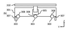
x方向車輪は、各端部の保持フランジ内に垂直方向に支持されて移動するサブシャーシ上に取り付けることができる。保持フランジにおけるサブシャーシの垂直移動は、ローラベアリング、ニードルベアリング、スライドベアリング、又はベアリングの使用によって低摩擦を有するようにされてもよい。1つの配置では、サブシャーシの垂直移動は、2段階油圧ラムを用いて達成されてもよい。油圧ラムは追加の段階を備えてもよいことが理解されるであろう。y方向車輪も同様に取り付けることができる。y方向車輪をサスペンションユニットで主シャーシに直接取り付け、x方向車輪を主シャーシに対して移動させることが有利であってもよいことが理解されるであろう。The x-direction wheels may be mounted on a sub-chassis which is supported and moves vertically within retaining flanges at each end. Vertical movement of the sub-chassis in the retaining flanges may be made to have low friction through the use of roller bearings, needle bearings, slide bearings, or bearings. In one arrangement, vertical movement of the sub-chassis may be achieved using a two-stage hydraulic ram. It will be appreciated that the hydraulic ram may include additional stages. The y-direction wheels may be mounted similarly. It will be appreciated that it may be advantageous to mount the y-direction wheels directly to the main chassis with suspension units and move the x-direction wheels relative to the main chassis.
代替的な配置では、サブシャーシの垂直移動は、保持フランジ内の歯付きラックによって達成されてもよい。歯付きラックは、電気モータによって歯付きピニオン駆動車輪によって駆動されてもよい。車輪サブシャーシデバイスは、各端部に歯付きラックアセンブリを備えてもよい。In an alternative arrangement, vertical movement of the sub-chassis may be accomplished by a toothed rack in the retaining flange. The toothed rack may be driven by a toothed pinion drive wheel by an electric motor. The wheel sub-chassis device may include a toothed rack assembly at each end.
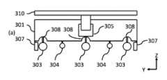
各サブシャーシは、サブシャーシと支持パッド又は保管コンテナ運搬シャーシとの間の相対的な垂直変位を検出及び報告するための1つ以上のセンサを備えることができる。Each subchassis may include one or more sensors for detecting and reporting relative vertical displacement between the subchassis and the support pad or storage container carrying chassis.
積荷取扱デバイスは、駆動モータに電力供給するための再充電可能なバッテリ及び/又はスーパーキャパシタをさらに備えてもよく、再充電可能なバッテリ及び/又はスーパーキャパシタは、積荷取扱デバイスの下側に位置付けられた誘導充電パッドを通して充電される。The load handling device may further include a rechargeable battery and/or a supercapacitor for powering the drive motor, the rechargeable battery and/or the supercapacitor being charged through an inductive charging pad positioned on the underside of the load handling device.
積荷取扱デバイスは、再充電可能なバッテリによって電力供給される搭載モータによって駆動されてもよい。代替的な配置では、搭載モータは、スーパーキャパシタによって電力供給されてもよい。又はいくつかの配置では、積荷取扱デバイスは、再充電可能なバッテリ及びスーパーキャパシタの両方を備えてもよい。スーパーキャパシタ充電(及び放電)時間は、バッテリ再充電時間と比較してはるかに高速であってもよいことが理解されるであろう。したがって、再充電可能バッテリ及びスーパーキャパシタの両方が使用される場合、積荷取扱デバイスは、スーパーキャパシタからの電力の迅速な増加又は補充、及び再充電可能バッテリからのより持続的な電力から利益を得ることができる。The load handling device may be driven by an on-board motor powered by a rechargeable battery. In an alternative arrangement, the on-board motor may be powered by a supercapacitor. Or in some arrangements, the load handling device may include both a rechargeable battery and a supercapacitor. It will be appreciated that the supercapacitor charge (and discharge) time may be much faster compared to the battery recharge time. Thus, when both a rechargeable battery and a supercapacitor are used, the load handling device may benefit from a quick increase or replenishment of power from the supercapacitor and a more sustained power from the rechargeable battery.
充電ロケーションは、積荷取扱デバイスがある期間にわたって留まる傾向がある場所に便利に位置付けられてもよいが、トラックネットワーク上の任意の場所であってもよい。典型的には、誘導パッドを提供するエネルギーは、特定の格子ロケーションでトラックレール間に位置付けられる。Charging locations may be conveniently located where the load handling devices tend to remain over a period of time, but may be anywhere on the track network. Typically, energy providing induction pads are positioned between the track rails at specific grid locations.
車輪のうちの1つ以上が駆動可能であってもよい。One or more of the wheels may be drivable.
車輪の第1のセット及び車輪の第2のセットのすべての車輪が駆動可能であってもよい。All of the wheels of the first set of wheels and the second set of wheels may be drivable.
車輪のセットの車輪のそれぞれが駆動されてもよい。このようにして、車輪のうちの1つがトラック面との接触を失っても、積荷取扱デバイスは依然として残りの車輪によって駆動される。さらに、これは、平坦でない表面上で積荷取扱デバイスの安定性を維持することを支援できる。Each of the wheels in the set of wheels may be driven. In this way, if one of the wheels loses contact with the track surface, the load handling device is still driven by the remaining wheels. Furthermore, this can help maintain the stability of the load handling device on uneven surfaces.
車輪の第1のセット及び車輪の第2のセットのうちの1つ以上は、ロック手段によってロック可能である。One or more of the first set of wheels and the second set of wheels are lockable by a locking means.
ロック手段は、x方向移動及び/又はy方向移動のために駆動モータをロックするための電気機械式ロックを備えることができる。積荷取扱デバイスが駐車ポジションにあるとき、例えば、保管コンテナを持ち上げるか又は置くとき、リフト車で移動するとき、又は充電ロケーションにあるとき、車輪の移動及び積荷取扱デバイスの移動を防止するために、モータはロックされてもよい。電気機械式ロックは、解除手段を有してもよい。例えば、解除手段は、制御システム又は技術者によって動作可能なスイッチであってもよい。ロックが適用されていないとき、車輪は自由に回転することができる。このようにして、積荷取扱デバイスが故障した場合、ロックを解除することができ、積荷取扱デバイスを単にメンテナンスエリアに押し出すか、又は引っ張ることができる。ロックは、回復デバイスによって解除可能であってもよい。積荷取扱デバイスが自由に移動できると、回復デバイスは、さらに、故障した積荷取扱デバイスを押したり引いたりすることができる。技術者がシステムの他のエリアで作業する場合に危険にさらされないように、回復デバイスは、故障した積荷取扱デバイスをメンテナンスエリアに移動させることができる。The locking means may comprise an electromechanical lock for locking the drive motor for x- and/or y-movement. The motor may be locked to prevent movement of the wheels and the load handling device when the load handling device is in a parking position, e.g. when lifting or placing a storage container, moving with a lift truck, or in a charging location. The electromechanical lock may have a release means. For example, the release means may be a switch operable by the control system or a technician. When the lock is not applied, the wheels are free to rotate. In this way, if the load handling device fails, the lock can be released and the load handling device can simply be pushed or pulled to a maintenance area. The lock may be releasable by a recovery device. Once the load handling device is free to move, the recovery device can further push or pull the failed load handling device. The recovery device can move the failed load handling device to a maintenance area so that the technician is not exposed to danger when working in other areas of the system.
積荷取扱デバイスは、識別タグ又はラベルを読み取るための、RFIDリーダ、スキャナ、及び/又はカメラをさらに備えることができる。The load handling device may further include an RFID reader, scanner, and/or camera for reading the identification tag or label.
積荷取扱デバイスは、識別タグを読み取る能力を有することができる。例えば、動作中、積荷取扱デバイスは、特定の保管コンテナを識別することができる。又は、積荷取扱デバイスは、タグがトラック内に若しくはトラックに沿って、又はワークステーションに配置された、システム内の特定のロケーションを識別することができる。The load handling device may have the ability to read an identification tag. For example, during operation, the load handling device may identify a particular storage container. Or, the load handling device may identify a particular location in the system where the tag is located in or along a truck or at a workstation.
積荷取扱デバイス及び支持された保管コンテナは、保管システム内の単一の格子空間のみを占有する設置面積を有する。The load handling device and supported storage container have a footprint that occupies only a single grid space within the storage system.
単一の格子空間又は格子ユニットは、単一の予約可能ロケーションであってもよい。このようにして、保管コンテナを運搬する積荷取扱デバイスは、実質的に衝突のリスクなしに、任意のトラック経路を横断することができる(積荷取扱デバイスが格子ロケーションの中心に置かれ、保管コンテナが積荷取扱デバイスの支持パッドの中心に適切に置かれていると仮定する)。A single grid space or grid unit may be a single reservable location. In this way, a load handling device carrying a storage container can traverse any truck route with virtually no risk of collision (assuming the load handling device is centered at the grid location and the storage container is properly centered on the load handling device's support pad).
積荷取扱デバイスは、トラックネットワークに沿った動きを監視及び制御するためのナビゲーション手段をさらに備えてもよい。積荷取扱デバイスは、中央制御設備から命令を受信し、データを送信するための通信手段をさらに備えることができる。積荷取扱デバイスは、近接センサをさらに備えていてもよい。The load handling device may further comprise navigation means for monitoring and controlling movement along the track network. The load handling device may further comprise communication means for receiving commands from and transmitting data to a central control facility. The load handling device may further comprise a proximity sensor.
積荷取扱デバイスは、保管システムの各フロアの不揮発性メモリ内にソフトウェアマップを有することができる。ソフトウェアマップは、物理的寸法、基準マーカの識別コード、基準マーカのポジション、例えば架台の存在などの予約可能なトラックロケーションの物理的属性、及び予約可能なトラックロケーション間のトラック経路接続のトポロジを含む、予約可能なトラックロケーションのそれぞれに関する情報を含むことができる。ソフトウェアマップは、デバイスコントローラが、(中央)制御設備によって提供される経路の各セグメントに対する軌道のパラメータを計算することを可能にしてもよい。The load handling device may have a software map in non-volatile memory for each floor of the storage system. The software map may contain information about each of the reservable track locations, including physical dimensions, identification codes of the reference markers, positions of the reference markers, physical attributes of the reservable track locations, e.g., the presence of a rack, and the topology of the truck path connections between the reservable track locations. The software map may enable the device controller to calculate trajectory parameters for each segment of the path provided by the (central) control facility.
デバイスコントローラは、車輪状態、支持パッド状態を選択するサーボ機構及び電気モータを制御し、積荷取扱デバイスをトラックに沿って移動させてもよい。積荷取扱デバイスは、コントローラに送信された応答メッセージを用いて、受信した全ての命令に肯定応答してもよい。The device controller may control servo mechanisms and electric motors that select wheel states, support pad states, and move the load handling device along the track. The load handling device may acknowledge all commands received with a response message sent to the controller.
積荷取扱デバイスのための少なくともいくつかのナビゲーション及び他の制御命令は、(中央)制御設備によって積荷取扱デバイスに提供される。At least some navigation and other control instructions for the load handling devices are provided to the load handling devices by a (central) control facility.
(中央)制御設備は、積荷取扱デバイスがフロアに沿って、フロアを横切って移動するための経路についての命令を提供してもよい。経路は、経路計画モジュールによって計画される。特定の時間における経路のセグメントは、予約され、積荷取扱デバイスへの命令として発行され、開始時間の前に記録されてもよい。経路又はトラックの個々のセグメントを横断するためのルート命令が、積荷取扱デバイス及び制御設備のクリアランスモジュールに発行される。The (central) control facility may provide instructions for the path for the load handling devices to move along and across the floor. The path is planned by a path planning module. Segments of the path at specific times may be reserved and issued as instructions to the load handling devices and recorded prior to the start time. Route instructions for traversing individual segments of the path or track are issued to the clearance modules of the load handling devices and the control facility.
経路計画モジュールは、積荷取扱デバイスが移動する前に、衝突リスクのない経路を計画することが理解されるであろう。一方、経路クリアランスモジュールは、保管システム内で動作している全ての積荷取扱デバイスからのポジション、速度及び状態報告を監視して、特定の積荷取扱デバイスのための意図された計画経路が衝突のリスクがないままであることを確実にする。計画された経路は、積荷取扱デバイスの故障、積荷取扱デバイスの性能低下、及び/又は積荷取扱デバイスへの又は積荷取扱デバイスからの通信障害によって、危険にさらされ、衝突又は別の形態の事故の危険にさらされる可能性がある。衝突リスクが識別された場合、経路クリアランスモジュールは、新たな衝突リスクのない経路が計画されてもよいように、経路計画モジュールに通知してもよい。It will be appreciated that the path planning module plans a collision risk free path before the load handling device moves. Meanwhile, the path clearance module monitors position, speed and status reports from all load handling devices operating within the storage system to ensure that the intended planned path for a particular load handling device remains collision risk free. The planned path may be compromised and at risk of collision or another form of accident due to load handling device failure, degradation of load handling device performance, and/or communication failure to or from the load handling device. If a collision risk is identified, the path clearance module may notify the path planning module so that a new collision risk free path may be planned.
積荷取扱デバイス自体は、デバイスコントローラをさらに備えていてもよい。デバイスコントローラは、中央制御設備から命令を受信し、肯定応答することができる。さらに、デバイスコントローラは、積荷取扱デバイスの移動を制御する際に使用するためのフィードバックのために、及び中央制御設備、特にクリアランスモジュールに提供するためのフィードバック又は報告のために、積荷取扱デバイス感知手段からの出力を使用してもよい。The load handling device itself may further comprise a device controller. The device controller may receive and acknowledge commands from the central control facility. Additionally, the device controller may use output from the load handling device sensing means for feedback for use in controlling movement of the load handling device and for feedback or reporting to provide to the central control facility, particularly the clearance module.
上述したように、積荷取扱デバイスは感知手段を備えてもよいことが理解されるであろう。センサは、トラックに近接する基準マーカを検出するためのレーザスキャナ、スキャナ、又はカメラ、トラック部材の交差を検出するための深さセンサ又はカメラ、車輪のうちの1つ以上の回転を監視及び報告するためのセンサ、及び車輪の回転を監視及び報告するための非駆動車輪検出器のうちの1つ以上であってもよい。積荷取扱デバイスの状態を監視するための他のセンサ及びデータコレクタが設けられてもよいことが理解されるであろう。積荷取扱デバイスは、基準マーカを通過するたびに、ポジション及び状態報告を中央コントローラ(制御設備)に送信してもよい。As mentioned above, it will be appreciated that the load handling device may be provided with sensing means. The sensors may be one or more of a laser scanner, scanner, or camera for detecting a reference marker in proximity to the track, a depth sensor or camera for detecting the intersection of track members, a sensor for monitoring and reporting the rotation of one or more of the wheels, and a non-driven wheel detector for monitoring and reporting the rotation of the wheels. It will be appreciated that other sensors and data collectors may be provided for monitoring the status of the load handling device. The load handling device may transmit a position and status report to a central controller (control facility) each time it passes a reference marker.
積荷取扱デバイスは、予期しない衝突リスクを警告するために、近接センサ、好ましくはデバイスの各側に近接センサをさらに備えてもよい。そのような状況では、温度上昇が緊急停止をトリガしてもよい。衝突リスクをもたらす予期しない物品の例は、意図された経路に直接ある他の積荷取扱デバイス、意図された経路に誤って落下した保管コンテナ、経路の端部をマーキングし、ナビゲーションエラー又はマッピングエラーのために遭遇する衝突防壁、ナビゲーションエラー又はマッピングエラーのために遭遇する架台、及び設備内で作業する(人間の)作業員を含むことができる。The load handling device may further comprise a proximity sensor, preferably on each side of the device, to warn of an unexpected collision risk. In such a situation, a temperature rise may trigger an emergency stop. Examples of unexpected items posing a collision risk may include other load handling devices directly in the intended path, storage containers accidentally dropped onto the intended path, collision barriers marking the end of the path and encountered due to navigation or mapping errors, platforms encountered due to navigation or mapping errors, and (human) personnel working within the facility.
システムは、データを収集し、システムの状態を監視するための調査ボットをさらに備えることができる。調査ボットの移動及び制御は、積荷取扱デバイスの移動及び制御と同様であってもよい。調査ボットは、生育通路に沿って移動し、各保管コンテナを調査することができる。例えば、調査ボットは、積荷取扱デバイスと同様であるが、支持パッドを有さず、センサパックを有する車両であってもよい。The system may further include a survey bot for collecting data and monitoring the status of the system. The movement and control of the survey bot may be similar to the movement and control of the load handling device. The survey bot may move along the growing aisle and survey each storage container. For example, the survey bot may be a vehicle similar to the load handling device but without the support pads and with a sensor pack.
システム内で動作し、説明されたデバイスと協働する他のタイプのボット又はモバイルデバイスが予想される。例えば、タスク特定デバイスである。Other types of bots or mobile devices are anticipated to operate within the system and cooperate with the described devices, e.g., task-specific devices.
制御設備
上述のように保管システムを制御し動作させるための制御機能が提供される。制御設備は、環境制御モジュール、マネージャモジュール、タスクプランナ、ボット経路計画モジュール、ボット経路クリアランスモジュール、通信モジュール、リフトタスクプランナ、ボット充電状態マネージャ、データ記憶及び持続モジュール、機械学習アルゴリズムにデータを提供するための長期データ記憶モジュール、回復、修理及びメンテナンス作業を容易にするために計画及びスケジュールを修正するための回復、修理及び/又はメンテナンスマネージャモジュール、並びにその以前の動作履歴に基づいてシステムを微調整するように設計された機械学習及び/又は人工知能モジュールのうちの1つ以上を備える。 Control Facility A control facility is provided for controlling and operating the storage system as described above. The control facility comprises one or more of an environmental control module, a manager module, a task planner, a bot path planning module, a bot path clearance module, a communications module, a lift task planner, a bot charge state manager, a data storage and persistence module, a long term data storage module for providing data to machine learning algorithms, a recovery, repair and/or maintenance manager module for modifying plans and schedules to facilitate recovery, repair and maintenance operations, and a machine learning and/or artificial intelligence module designed to fine tune the system based on its previous operating history.
1つ以上の保管通路、チャンバ、若しくはフロアに対して独立した空気温度、1つ以上の通路、チャンバ、若しくはフロアに対して独立した空気湿度、1つ以上の通路、チャンバ、若しくは生育フロアに対して独立した空気流のうちの1つ以上は、制御デバイスによって制御可能であってもよく、及び/又は、制御設備は、計画及び/若しくは管理を実行してもよく、制御設備は、正しい保管コンテナが各段階で取り扱われていることを確認してもよく、制御設備は、各動作の監査記録を作成してもよい。One or more of the independent air temperature for one or more storage aisles, chambers, or floors, independent air humidity for one or more aisles, chambers, or floors, independent air flow for one or more aisles, chambers, or growing floors may be controllable by a control device and/or the control equipment may perform planning and/or management, the control equipment may ensure that the correct storage containers are handled at each stage, and the control equipment may create an audit record of each operation.
制御設備は、1つ以上のコンピュータを備えてもよい。1つ以上のコンピュータは、農業システムと物理的に同一場所に位置付けられてもよく、又は1つ以上のコンピュータは、農業システムから遠隔に位置付けられてもよい。制御設備は、インターネットを介してアクセスされてもよく、及び/又はクラウドサービスに基づいてもよい。中央制御設備は、農業システムを管理する責任を負うことができる。積荷取扱デバイス又はボット、管理ステーションなどのシステムの個々の構成要素は、中央制御設備と通信するローカル又は個々の制御設備を備えることができる。中央制御設備は、農業システム内の個々の構成要素の制御システムを協調させることができることが理解されるであろう。農業システム内の個々の構成要素は、少なくともある程度まで、自律的又は半自律的に動作してもよい。The control facility may comprise one or more computers. The one or more computers may be physically co-located with the agricultural system, or the one or more computers may be located remotely from the agricultural system. The control facility may be accessed via the internet and/or may be based on cloud services. A central control facility may be responsible for managing the agricultural system. Individual components of the system, such as load handling devices or bots, management stations, etc., may comprise local or individual control facilities that communicate with the central control facility. It will be appreciated that the central control facility may coordinate the control systems of the individual components in the agricultural system. Individual components in the agricultural system may operate, at least to some extent, autonomously or semi-autonomously.
1つ以上のコンピュータは、1つ以上のメモリ及び1つ以上のプロセッサを備えてもよく、1つ以上のメモリは、記憶設備のための制御設備を実装するように、1つ以上のコンピュータによって実行可能なプログラム命令を含む。システム又は制御設備は、複数の処理構成要素(モジュール)を備えることができ、それぞれは、少なくとも1つのモジュールを有するように構成された制御システムのそれぞれの部分を実行するようにそれぞれ構成される。The one or more computers may include one or more memories and one or more processors, and the one or more memories include program instructions executable by the one or more computers to implement a control facility for the storage facility. The system or control facility may include multiple processing components (modules), each configured to execute a respective portion of a control system configured to have at least one module.
制御設備は、任意の適切なアーキテクチャを含むことができる。制御設備のソフトウェアモジュールは、システム内のいくつかの異なる物理的ロケーションに位置付けられる、又は例えば、クラウドベースのシステムを介してシステムから遠隔に位置付けられる、多くのコンピュータ上で実行するように実装されてもよい。各ソフトウェアモジュールは、それ自体のデータ構造の維持と、不揮発性記憶媒体又はデバイスへのそれらのデータ構造の持続性とを担うことができる。The control facility may include any suitable architecture. The software modules of the control facility may be implemented to run on many computers located at several different physical locations within the system, or located remotely from the system, for example via a cloud-based system. Each software module may be responsible for maintaining its own data structures and persisting those data structures to a non-volatile storage medium or device.
データは、任意の適切な手段によって露出され、モジュール間で転送されてもよい。例えば、データを交換するように設計されたインタフェースへのコールと、データを交換するように設計されたメッセージングプロトコルとを含む。Data may be exposed and transferred between modules by any suitable means, including, for example, calls to interfaces designed to exchange data and messaging protocols designed to exchange data.
ソフトウェアモジュールは、並行して連続的に実行されてもよい。The software modules may be executed in parallel or serially.
ソフトウェアの状態変化は、下流のモジュールに影響を及ぼしてもよい。状態変化は、前のモジュールの通知時に直ちに発生してもよい。典型的には、状態変化は、タスクキュー内のタスクの下流エントリをもたらしてもよいか、又はタスクの完了は、状態変化をもたらしてもよい。A state change in the software may affect downstream modules. The state change may occur immediately upon notification of a previous module. Typically, the state change may result in a downstream entry of the task in a task queue, or completion of the task may result in the state change.
環境制御モジュールは、保管システム内の環境を制御することができる。環境制御は、地球規模/設備全体であってもよく、又は環境制御は、保管通路、保管通路のセクション、又はチャンバに局所化されてもよい。環境制御モジュールは、温度及び空気流を制御することができる。The environmental control module can control the environment within the storage system. The environmental control can be global/facility-wide or the environmental control can be localized to a storage aisle, a section of a storage aisle, or a chamber. The environmental control module can control temperature and airflow.
システムプランナ又はマネージャモジュールは、代替可能な保管コンテナのグループを作成し、側部通路内の隣接する保管ロケーションに割り当てることができるように、特定のタイムスロットにおける特定の複数の保管コンテナに対する需要を識別する。これは、通路の中心に最も近い保管コンテナが最初にアクセスされることができるので、代替可能なグループの部材にアクセスするために保管コンテナの一時的なリロケーションが必要とされないので、非常に効率的な最適化であってもよい。The system planner or manager module identifies demand for a particular number of storage containers in a particular time slot so that groups of interchangeable storage containers can be created and assigned to adjacent storage locations in the side aisle. This may be a very efficient optimization since temporary relocation of storage containers is not required to access members of an interchangeable group since the storage containers closest to the center of the aisle can be accessed first.
タスクプランナモジュールは、取り出し前の保管ロケーションにおける保管コンテナの予想時間を評価し、最適化アルゴリズムを実行して、発送ワークステーションに最も近い通路中の最短保管期間の保管コンテナを、収穫機器を有するフロアに配置し、したがって、必要とされる総リフトサービス時間を最小化し、したがって、必要とされる移動の数を最小化する。The task planner module evaluates the expected time of the storage container in the storage location before retrieval and runs an optimization algorithm to place the storage container with the shortest storage time in the aisle closest to the dispatch workstation on the floor with the harvesting equipment, thus minimizing the total lift service time required and therefore the number of trips required.
タスクプランナモジュールは、計画を処理し、構築する。タスクプランナによって作成された計画は、需要予測が発展するにつれて連続的に修正される。タスクプランナは、特定のタイムスロットで需要を満たすようにプランを修正することができる。タスクは、タスク計画ホリゾン(horizon)制限時間で作成され、計画される。The task planner module processes and builds the plan. The plan created by the task planner is continuously revised as the demand forecast evolves. The task planner can revise the plan to meet the demand in a particular time slot. Tasks are created and planned with the task planning horizon time limit.
保管システムボット又は積荷取扱デバイス経路計画モジュールは、積荷取扱デバイスが取るべきルートを計画するために、経路の各セグメントに対する積荷取扱デバイス横方向制御システムの推定整定時間の間、オーバーシュート予約可能トラックロケーションを予約することができる。経路のセグメントが、積荷取扱デバイスが移動を開始する予約可能ロケーションから、積荷取扱デバイスが次に停止するように計画されている予約可能ロケーションまでとして定義される場合、これは、積荷取扱デバイスがxとyとの間又はyとxとの間で車輪構成を変更する際の一時停止を含む。The storage system bot or the load handling device path planning module can reserve overshoot reservable track locations for the estimated settling time of the load handling device lateral control system for each segment of the path to plan the route the load handling device should take. If a segment of the path is defined as the reservable location where the load handling device starts moving to the next reservable location where the load handling device is planned to stop, this includes pauses as the load handling device changes wheel configuration between x and y or between y and x.
経路計画モジュールは、特定の保管コンテナ移動タスクのためにトラックに沿って予約可能ロケーションを予約する。積荷取扱デバイス経路計画モジュールの別個のインスタンスが、各フロアに対して実行されてもよい。積荷取扱デバイス経路計画モジュールは、フロア全体の全ての予約可能ロケーションについて予約テーブルを作成する。各予約可能ロケーションは、異なる時間帯に異なる積荷取扱デバイスのための多くの予約を有することができる。大型積荷取扱デバイス間の衝突は非常に長い回復手順を必要とすることがあるので、積荷取扱デバイス経路計画モジュールは、積荷取扱デバイスの横方向制御システムの推定整定時間のためにオーバーシュート予約可能ロケーションを予約して、積荷取扱デバイス間の衝突のリスクをさらに最小限に抑えることができる。積荷取扱デバイス経路計画モジュールは、そのデフォルト挙動の一部としてこれらの潜在的ルートを識別し、評価する。いくつかの例では、積荷取扱デバイスが保管コンテナを運搬していない場合、保管ロケーションの下のルートを計画することが可能であってもよい。The path planning module reserves reservable locations along the track for a particular storage container movement task. A separate instance of the load handling device path planning module may run for each floor. The load handling device path planning module creates a reservation table for all reservable locations across floors. Each reservable location can have many reservations for different load handling devices at different times. Since collisions between large load handling devices can require very long recovery procedures, the load handling device path planning module may reserve overshoot reservable locations for the estimated settling time of the load handling device's lateral control system to further minimize the risk of collisions between the load handling devices. The load handling device path planning module identifies and evaluates these potential routes as part of its default behavior. In some examples, if the load handling device is not carrying a storage container, it may be possible to plan a route under the storage location.
積荷取扱デバイス又はボット経路クリアランスモジュールは、積荷取扱デバイスが辿るべき計画されたルートが空いていることを保証するために、積荷取扱デバイスによる各予約可能ロケーションの占有の記録を作成し、積荷取扱デバイスが、保管コンテナのピックアップと保管コンテナの配置との間のそれらの計画された経路上の各予約可能ロケーションを横切るときに入るためのクリアランスを与えられている予約可能ロケーションの記録を作成する。典型的には、積荷取扱デバイスは、予約可能ロケーションに入るポジション、予約可能ロケーションを中心とするポジション、及び予約可能ロケーションから出るポジションを報告する。積荷取扱デバイスクリアランスモジュールは、一方又は両方の積荷取扱デバイスの電気機械的故障、一方又は両方の積荷取扱デバイスとの通信故障、想定された運動学的及び物理的プロファイルを維持するための積荷取扱デバイスの故障の結果としての積荷取扱デバイス間の衝突を防止するために必要である。The load handling device or bot path clearance module creates a record of the occupancy of each bookable location by the load handling device to ensure that the planned route to be followed by the load handling device is clear, and creates a record of the bookable locations that the load handling device has been given clearance to enter as it crosses each bookable location on their planned route between picking up the storage container and placing the storage container. Typically, the load handling device reports its position entering the bookable location, its position centered on the bookable location, and its position exiting the bookable location. The load handling device clearance module is necessary to prevent collisions between load handling devices as a result of electromechanical failure of one or both load handling devices, failure of communication with one or both load handling devices, failure of the load handling device to maintain the expected kinematic and physical profile.
積荷取扱デバイス選択及び経路計画モジュールは、持ち上げ及び/又は輸送タスクを実行するために利用可能なボットを選択する役割を果たしてもよい。The load handling device selection and path planning module may be responsible for selecting available bots to perform lifting and/or transport tasks.
通信モジュールは、他のモジュールとマネージャとの間の通信を担うことができる。保管設備の各構成要素は、通信モジュールを備えてもよい。各積荷取扱デバイス又はボットは、通信モジュールを備えてもよい。各リフトは、通信モジュールを備えてもよい。各ワークステーションは、通信モジュールを備えてもよい。The communication module may be responsible for communication between the other modules and the manager. Each component of the storage facility may be equipped with a communication module. Each load handling device or bot may be equipped with a communication module. Each lift may be equipped with a communication module. Each workstation may be equipped with a communication module.
リフトタスクプランナモジュールは、リフト車停止のシーケンスを生成する。好ましい実施形態では、リフトタスクプランナモジュールは、リフト動作を選択して、タスクプランナモジュールによって決定された優先順位で積荷取扱デバイスの移動のシーケンスを維持するが、待ち行列が形成されるときはいつでも、リフトタスクプランナモジュールは、リフトスループットを最大にするようにピックアップ及びドロップオフ計画を切り替える。2階建てリフト車の場合には、これは、隣接するフロアでのピックアップ及びドロップオフ動作を同時に行うために特定のピックアップを遅延させることを意味する。The lift task planner module generates a sequence of lift car stops. In the preferred embodiment, the lift task planner module selects lift operations to maintain the sequence of load handling device movements in the priority order determined by the task planner module, but whenever a queue forms, the lift task planner module switches pick-up and drop-off plans to maximize lift throughput. In the case of a double-decker lift car, this means delaying certain pick-ups in order to accommodate simultaneous pick-up and drop-off operations at adjacent floors.
回復、修復、及びメンテナンスマネージャモジュールは、以下を含むがこれらに限定されないシステム障害を自動トリアージする:
1.積荷取扱デバイスの故障、典型的には、モジュールは、故障した積荷取扱デバイスが占有する予約可能ロケーションが除外されることを指定するためにデータ内にフラグを設定し、任意のアクセス不可能な保管コンテナがアクセス不可能であることを指定するためにデータ内にフラグを設定し、任意の故障した積荷取扱デバイスは、タスク不可能である、すなわち、タスクを割り当てられるのに適していない。モジュールは、経路計画モジュールに実行するように要求し、そのアルゴリズムは、新たに除外された予約可能ロケーションを回避する代替ルートを探して計画する。複数の障害のために計画可能でない任意のタスクは、メンテナンス及び回復ミッションを先に進めることを選ぶことができる人間の管理者にフラグが立てられる。
2.リフト故障、典型的には、モジュールは、リフトが非稼働であることを指定するためにデータ内にフラグを設定し、任意の動けなくなった積荷取扱デバイスがタスク不可能であり、(動けなくなった積荷取扱デバイス上の)任意のアクセス不可能な保管コンテナがアクセス不可能であるとしてフラグを立てられることを指定するためにデータ内にフラグを設定する。モジュールは、リフトタスクプランナモジュールに、全ての未解決のリフトタスクを再計画するように要求する。 The Recovery, Repair, and Maintenance Manager module automatically triages system failures including but not limited to:
1. Load handling device failure: typically the module sets a flag in the data to designate that the bookable location occupied by the failed load handling device is excluded, sets a flag in the data to designate that any inaccessible storage containers are inaccessible, and any failed load handling device is task-unavailable, i.e., not suitable to be assigned a task. The module calls on the path planning module to run, whose algorithms seek and plan alternative routes that avoid the newly excluded bookable location. Any tasks that are not plannable due to multiple failures are flagged to a human administrator who can choose to proceed with a maintenance and recovery mission.
2. Lift failure - typically the module sets a flag in the data to designate the lift as out of service, sets a flag in the data to designate that any stuck load handling devices are task-unavailable, and any inaccessible storage containers (on the stuck load handling devices) are flagged as inaccessible. The module requests the lift task planner module to re-plan all outstanding lift tasks.
回復、修理、及びメンテナンスマネージャモジュールはまた、人間による回復、人間による修理、及び人間によるメンテナンス作業のために保管設備を構成するために使用することができる。例えば、故障したボット又は積荷取扱デバイスの手動回復は、安全停止されるか又は他のフロアに移動されるかのいずれかのフロア上の全ての積荷取扱デバイスを用いて達成されてもよく、次いで、積荷取扱デバイスが人間と衝突することを物理的に防止するために、トラックにわたって安全バリアが配置される。回復、修理及びメンテナンスマネージャモジュールはまた、すべての隔離されたトラックを除外するためにデータ内にフラグを設定し、その結果、フロアの隔離されていないセクション上で通常の生産を再開することができる。回復が完了すると、フロア上の全ての積荷取扱デバイスは停止されるか、別のフロアに移動される。物理的な安全バリアが除去され、全ての分離されたトラックを除外するためにデータに設定されたフラグがクリアされる。積荷取扱デバイス経路計画モジュールは、次いで、積荷取扱デバイスの動作がフロア上で再開されると、積荷取扱デバイスの経路を計画するときに、全ての除外されていない予約可能ロケーションを使用することができる。The recovery, repair, and maintenance manager module can also be used to configure the storage facility for human recovery, human repair, and human maintenance operations. For example, manual recovery of a failed bot or load handling device may be accomplished with all load handling devices on the floor either safety stopped or moved to another floor, and then a safety barrier is placed across the tracks to physically prevent the load handling devices from colliding with humans. The recovery, repair, and maintenance manager module also sets a flag in the data to exclude all quarantined tracks so that normal production can resume on the non-quarantined sections of the floor. Once recovery is complete, all load handling devices on the floor are stopped or moved to another floor. The physical safety barriers are removed and the flags set in the data to exclude all quarantined tracks are cleared. The load handling device path planning module can then use all non-excluded bookable locations when planning the paths of the load handling devices once operation of the load handling devices resumes on the floor.
機械学習及び/又は人工知能モジュールは、計画及び生産性を向上させ、その以前の動作履歴に基づいてシステムを微調整するように設計される。モジュールは、少なくとも以下の方法で機械学習及び人工知能技術を使用することができる:
1.積荷取扱デバイスの移動に関する長期データを分析し、積荷取扱デバイスの異なるクラス(モデル)にわたって集計して、経路計画で使用される物理モデルを定義するために使用されるパラメータを精緻化。
2.フロア上の可能な積荷取扱デバイスルートの識別、及び選択されたルートの最適化。
3.リフト移動の長期データを分析し、リフトの異なるクラス(モデル)にわたって集計して、リフト計画で使用される物理モデルを定義するために使用されるパラメータを精緻化。 The machine learning and/or artificial intelligence module is designed to improve planning and productivity and fine-tune the system based on its previous operating history. The module may use machine learning and artificial intelligence techniques in at least the following ways:
1. Long-term data on the movements of load handling devices is analyzed and aggregated across different classes (models) of load handling devices to refine the parameters used to define the physical models used in route planning.
2. Identification of possible load handling device routes on the floor and optimization of the selected route.
3. Long-term data of rift movement is analysed and aggregated across different classes (models) of rifts to refine the parameters used to define the physical models used in rift planning.
機械学習及び/又は人工知能モジュールは、以下の人工知能及び機械学習技術を使用してもよいが、それらに限定されない:
1.機械学習
2.ニューラルネットワーク
3.機械学習(一般)
4.教師あり学習
5.確率的グラフィカルモデル
6.サポートベクターマシン
7.バイオインスパイアードアプローチ(蟻コロニー最適化を含むが、これに限定されない)
8.分類及び回帰ツリー
9.深層学習
10.ルール学習
11.教師なし学習
12.強化学習
13.インスタンスベースの学習
14.潜在表現
15.マルチタスク学習
16.論理及び関係学習
17.論理プログラミング
18.エキスパートシステム
19.記述論理
20.論理プログラミング(一般的)
21.ファジィ論理2
22.オントロジー工学
23.確率的推論 The machine learning and/or artificial intelligence module may use the following artificial intelligence and machine learning techniques, including, but not limited to:
1.
4.
8. Classification and
21.
22.
トラック及び積荷取扱デバイスは、積荷取扱デバイスが予約可能ロケーションの概念上の「中心」をマークする基準マーカに位置付けられたときに、積荷取扱デバイスが、静止しているか又は隣接するロケーションで移動しているかにかかわらず、他の積荷取扱デバイスとの衝突リスクがないように配置されることが理解されるであろう。It will be appreciated that the trucks and load handling devices are positioned such that when the load handling device is positioned at a reference marker that marks the notional "centre" of a bookable location, there is no risk of collision with other load handling devices, whether the load handling device is stationary or moving at an adjacent location.
格子ベースのトラックネットワーク上の直交方向への方向変更のための積荷取扱デバイスの位置合わせは、積荷取扱デバイス上のレーザスキャナ、スキャナ、又はカメラと、予約可能ロケーションにおける直交トラックの交差のポジションをマークするトラックに近接する基準マーカとを使用して達成されることが理解されるであろう。この配置は、積荷取扱デバイスの車輪とトラックとの直交方向における正確な位置付けを提供してもよい。It will be appreciated that alignment of the load handling device for orthogonal direction changes on the grid-based track network is accomplished using a laser scanner, scanner, or camera on the load handling device and fiducial markers proximate the tracks that mark the position of the intersection of the orthogonal tracks at the bookable location. This arrangement may provide precise positioning of the wheels of the load handling device and the tracks in the orthogonal direction.
保管ロケーション内での積荷取扱デバイスの位置合わせは、積荷取扱デバイス上のスキャナ、レーザスキャナ、又はカメラと、予約可能ロケーションの概念上の「中心」ポイントをマークするトラックに近接する基準マーカとを使用して達成されることが理解されるであろう。これは、架台に対する保管コンテナの正確な位置付けを提供する。It will be appreciated that alignment of the load handling device within the storage location is accomplished using a scanner, laser scanner, or camera on the load handling device and a fiducial marker adjacent to the truck that marks the notional "center" point of the bookable location. This provides precise positioning of the storage container relative to the rack.
直交又は格子ベースのトラック構造に沿った動きを追跡及び制御するための積荷取扱デバイスナビゲーションシステムは、センサ情報を使用することによって達成される。A cargo handling device navigation system for tracking and controlling movement along a cartesian or grid-based track structure is achieved by using sensor information.
設備内の積荷取扱デバイス又は積荷取扱デバイスの動作に使用する際に、各フロアの詳細なマップを各積荷取扱デバイスにダウンロードする。マップに関係付けられたデータは、積荷取扱デバイスの動作制御システムに、その軌道を計算し、軌道に沿ったその動作を制御するのに十分なデータを提供する。マップとともに含まれるデータは、予約可能ロケーションの物理的寸法、予約可能ロケーション上の基準マーカのポジション、予約可能ロケーションと任意の隣接予約可能ロケーションとの間の接続を含むがこれらに限定されない。A detailed map of each floor is downloaded to each load handling device when it is used in the load handling device or operation of the load handling device within a facility. The data associated with the map provides the motion control system of the load handling device with sufficient data to calculate its trajectory and control its movement along the trajectory. Data included with the map includes, but is not limited to, the physical dimensions of the bookable location, the position of a fiducial marker on the bookable location, and the connections between the bookable location and any adjacent bookable locations.
積荷取扱デバイスが移動するための命令は、コントローラの積荷取扱デバイス経路クリアランスモジュールによって生成され、コントローラの通信モジュールによって積荷取扱デバイスへ/から送信される。積荷取扱デバイスが移動するための指示は、移動の開始時刻を有し、開始時刻より前に積荷取扱デバイスに送信される。積荷取扱デバイスは、命令が受信されたという確認を送信してもよい。このプロトコルは、100%のメッセージ配信が保証又は期待されないので、移動命令が必要に応じて数回送信されることを可能にし、通信に回復力を加える。Instructions for the load handling device to move are generated by the load handling device path clearance module of the controller and transmitted to/from the load handling device by the communication module of the controller. Instructions for the load handling device to move have a start time for the move and are transmitted to the load handling device prior to the start time. The load handling device may transmit a confirmation that the instruction was received. This protocol allows the move instruction to be transmitted several times as necessary, adding resilience to the communication since 100% message delivery is not guaranteed or expected.
直交方向への方向変更のための積荷取扱デバイスの位置合わせは、積荷取扱デバイス上のレーザスキャナ、スキャナ、又はカメラと、ポイントをマーキングするトラックに近接した基準マーカとを使用して達成することができる。これにより、積荷取扱デバイスの車輪をトラックに対して直交方向に正確に位置付けることができる。直交方向への変更が許可されない予約可能ロケーションに対して、基準マーカは、予約可能ロケーションの概念上の中心ポイントに配置されてもよい。Alignment of the load handling device for orthogonal direction changes can be accomplished using a laser scanner, scanner, or camera on the load handling device and a fiducial marker proximate to the track marking point, allowing the wheels of the load handling device to be accurately positioned orthogonally relative to the track. For bookable locations where orthogonal changes are not permitted, the fiducial marker may be placed at a notional center point of the bookable location.
保管ロケーション内の積荷取扱デバイスの位置合わせは、積荷取扱デバイス上のスキャナ、レーザスキャナ、又はカメラと、予約可能ロケーションの中心ポイントをマークするトラックに近接する基準マーカとを使用して達成されてもよい。これは、架台に対する保管コンテナの正確な位置付けを提供する。Alignment of the load handling device within the storage location may be accomplished using a scanner, laser scanner, or camera on the load handling device and a fiducial marker adjacent to the truck that marks the center point of the bookable location. This provides precise positioning of the storage container relative to the rack.
使用
保管システムを使用する方法が提供される。方法は、積荷取扱デバイスを使用して保管コンテナを輸送及び配置するステップと、保管コンテナを保管ロケーションに配置するステップと、保管ロケーションから保管コンテナを取り出すステップと、保管コンテナを保管通路に配置するステップと、任意選択で、要件に従って保管通路内の環境を制御するステップとの1つ以上のステップを含むことができる。 Use A method of using the storage system is provided, the method may include one or more of the steps of transporting and placing a storage container using a load handling device, placing the storage container at a storage location, retrieving the storage container from the storage location, placing the storage container in a storage aisle, and optionally controlling the environment in the storage aisle according to requirements.
積荷取扱デバイスが、中央制御設備によって保管ロケーションの一対の架台上に保管コンテナを配置するように指示された場合、積荷取扱デバイスは、保管コンテナを搬送しながら、積荷取扱デバイスが所望の保管ロケーションに隣接するまでアクセス通路に沿って移動する。支持パッドが上昇された状態で、積荷取扱デバイスは、支持パッド上の保管コンテナが側部通路内の架台の上方にあるように、保管通路から側部通路内に移動する。保管通路への経路は、保管コンテナが架台上に載っている保管ロケーションを回避するように、制御設備によって計算又は計画されることが理解されるであろう。典型的には、積荷取扱デバイスは、保管通路内の他の利用可能な保管ロケーションへのアクセスを妨げないように、保管コンテナを保管ロケーションに配置するように指示されてもよい。指示されたロケーションに位置付けられるとき、積荷取扱デバイスは支持パッドを下降させ、架台によって支持された保管コンテナを保管ロケーションに残す。次いで、積荷取扱デバイスは、逆方向に、又は別の指示されたルートを介して移動して、アクセス通路に戻る。When the load handling device is instructed by the central control facility to place a storage container on a pair of cradles at a storage location, the load handling device moves along the access aisle while carrying the storage container until the load handling device is adjacent to the desired storage location. With the support pads raised, the load handling device moves from the storage aisle into the side aisle such that the storage container on the support pads is above the cradles in the side aisle. It will be understood that the route to the storage aisle is calculated or planned by the control facility to avoid the storage location where the storage container is resting on the cradle. Typically, the load handling device may be instructed to place the storage container at the storage location so as not to block access to other available storage locations in the storage aisle. When positioned at the indicated location, the load handling device lowers the support pads, leaving the storage container supported by the cradles at the storage location. The load handling device then moves in the opposite direction, or via another indicated route, back to the access aisle.
積荷取扱デバイスが、中央制御設備によって保管ロケーションから一対の架台上の保管コンテナを取り出すように指示された場合、積荷取扱デバイスは、積荷取扱デバイスが特定の保管コンテナを含む保管ロケーションを含む側部通路に隣接するまでアクセス通路に沿って移動する。支持パッドが下げられた状態で、積荷取扱デバイスは、支持パッドが目標保管コンテナの下方に位置付けられるまで、側部通路内に移動する。次に、積荷取扱デバイスは、支持パッドを上昇させ、保管コンテナを架台の上方に持ち上げる。保管コンテナを運搬すると、積荷取扱デバイスは、架台との衝突を回避するために支持パッドが上昇ポジションにある状態で、保管エリアを通ってアクセス通路へと逆に移動する。アクセス通路トラック上に来ると、積荷取扱デバイスは、次の目的地にナビゲートする前に支持パッドを下降させてもよい。When the load handling device is instructed by the central control facility to retrieve a storage container on a pair of cradles from a storage location, the load handling device moves along the access aisle until it is adjacent to a side aisle containing a storage location that contains the particular storage container. With the support pads lowered, the load handling device moves into the side aisle until the support pads are positioned below the target storage container. The load handling device then raises the support pads, lifting the storage container above the cradles. Once the storage container is delivered, the load handling device moves back through the storage area to the access aisle with the support pads in the raised position to avoid collision with the cradles. Once on the access aisle track, the load handling device may lower the support pads before navigating to its next destination.
同じアイテムの複数の同一の保管コンテナがあることを中央制御システムが認識している場合、制御設備は、保管コンテナのグループの代替可能な性質を利用し、代替可能な保管コンテナを同じ保管通路に配置することができることが理解されるであろう。代替可能グループの保管コンテナのいずれかが必要とされるとき、コントローラ計画モジュールは、アクセス通路に最も近い代替可能グループ内の保管コンテナを選択する。すなわち、制御設備は、保管通路内の他の保管コンテナを一時的に再配置することなくアクセスすることができる保管コンテナを選択する。It will be appreciated that if the central control system knows that there are multiple identical storage containers for the same item, the control facility can take advantage of the fungible nature of a group of storage containers and place the fungible storage containers in the same storage aisle. When any of the storage containers in the fungible group are needed, the controller planning module selects the storage container in the fungible group that is closest to the access aisle. That is, the control facility selects the storage container that can be accessed without temporarily relocating other storage containers in the storage aisle.
システムによって必要とされる積荷取扱デバイスの数は、通路及び/又は保管ロケーションの数、又はフロアの数ではなく、保管コンテナの移動の数によって決定されてもよい。The number of load handling devices required by the system may be determined by the number of storage container movements rather than the number of aisles and/or storage locations, or the number of floors.
保管コンテナは積み重ねられないことが理解されるであろう。したがって、保管システム及び取り出しシステムは、積み重ねることができないコンテナ、又は可変高さの頂部若しくは平坦でない上面を有するコンテナを収容することができる。It will be understood that the storage containers are not stackable. Thus, the storage and retrieval systems can accommodate containers that are not stackable or that have tops of variable heights or non-flat top surfaces.
このようにして、本発明は、従来技術の問題のいくつかに対処し、物品保管及び取り出しシステムのためのシステム、方法及びデバイスを提供する。In this manner, the present invention addresses some of the problems of the prior art and provides a system, method and device for an item storage and retrieval system.
他のシステムとの統合
保管及び取り出しシステム並びに生育設備は、他の自動化システムと統合されてもよい。統合は、以下を含んでいてもよい:
・検索された、又はピッキングされた商品を含むトート又はコンテナを、食料品店の顧客フルフィルメントセンターの機械的処理機器の内側に、又は内側に向かって輸送するコンベヤ。いくつかの配置では、発送ワークステーションは、自動食料雑貨店顧客フルフィルメントセンター内で使用されるトート、特に商品内部の機械的処理機器及びシステムと互換性があるように設計されてもよい。
・トートを輸送する自律空輸車両又はドローン
・トートを輸送する自律陸上車両又は自律誘導車両
・トートを輸送する任意の形態の人間が操作する貨物車両
・トートを輸送する任意の形態の磁気浮上輸送システム
・自動食料雑貨店顧客フルフィルメントセンターの注文管理及び注文予測システムと、保管システムのプランナー/マネージャモジュールとの間の任意の形態の統合。特に、そのような統合が使用されて、特定の時間スロットでの自動食料品店顧客フルフィルメントセンターへの製品利用可能性を確実にする場合である。 Integration with other systems The storage and retrieval system and the growing facility may be integrated with other automated systems. Integration may include:
- A conveyor that transports the totes or containers containing the searched or picked items to or toward the interior of the mechanical processing equipment of the grocery store customer fulfillment center. In some arrangements, the dispatch workstation may be designed to be compatible with the tote and especially item internal mechanical processing equipment and systems used within an automated grocery store customer fulfillment center.
- Autonomous air vehicles or drones transporting totes - Autonomous ground vehicles or autonomous guided vehicles transporting totes - Any form of human operated cargo vehicle transporting totes - Any form of magnetic levitation transport system transporting totes - Any form of integration between the order management and order forecasting system of the automated grocery store customer fulfillment center and the planner/manager module of the storage system, especially where such integration is used to ensure product availability to the automated grocery store customer fulfillment center at specific time slots.
単なる例として、添付の図面を参照して、本発明の実施形態を説明するが、同様の参照番号は、同様の特徴に対して使用されている。Embodiments of the present invention will now be described, by way of example only, with reference to the accompanying drawings, in which like reference numerals are used for like features, in which:
本発明は、より大きなシステムの一部を形成してもよい。本明細書で説明されるシステム、方法、及びデバイスは、例示にすぎず、説明される装置及び機器の他の組み合わせ及び構成が、本明細書で説明される本発明の範囲から逸脱することなく、本開示の発明者らによって予期されることを理解されたい。The present invention may form part of a larger system. It is to be understood that the systems, methods, and devices described herein are merely exemplary, and that other combinations and configurations of the described apparatus and equipment are contemplated by the inventors of the present disclosure without departing from the scope of the invention described herein.
上述したように、図1から図4は、従来技術の保管システムの代表的な図面である。As mentioned above, Figures 1 to 4 are representative diagrams of prior art storage systems.
本発明の保管システム、積荷取扱デバイス、保管ロケーション、使用の方法及び制御設備は、残りの図面に図示されている。The storage system, cargo handling device, storage locations, method of use and control equipment of the present invention are illustrated in the remaining drawings.
図5から図7は、保管フロアの概略図を示す。保管フロアはユニットの格子に分割され、各ユニットは指定された機能を有する。通路2は、保管フロアの幅及び長さにわたって配置される。典型的には、アクセス通路2は2ユニット幅であり、図1に示すように保管フロアの各端部を横切って配置されている。端部の間で、アクセス通路2は、アクセス通路2に対して垂直にかつ保管フロアの長さに沿って延びる保管通路2によって接合される。保管通路2は、典型的には1ユニット幅である。保管通路2に隣接して保管ロケーション1がある。保管ロケーション1は、アクセス通路2又は保管通路2のいずれかから積荷取扱デバイスによってアクセスされてもよい。Figures 5 to 7 show schematic diagrams of a storage floor. The storage floor is divided into a grid of units, each unit having a designated function.
上述したように、各保管ロケーション1には、保管コンテナを支持するための架台が設けられている。積荷取扱デバイスが保管コンテナを輸送していないとき、積荷取扱デバイスは、任意のアクセス可能なルートを介して、任意の保管フロア通路又は保管ロケーションまでx-方向及びy-方向に移動することができる。しかしながら、積荷取扱デバイスは、保管ロケーションを通って一方向(x)に移動することができ、直交方向に保管ロケーションを横断しようとするいかなる試みも、積荷取扱デバイスと支持架台との間の衝突をもたらすことがある。As mentioned above, each
図5に図示するように、メンテナンスエリア3は、フロアの指定された保管ロケーション1のエリアの中心を通って位置付けられている。さらに、メンテナンスエリア3は、フロアの長い側面に沿って位置付けられ、保管フロアの短い側面に沿ったいくつかのユニットロケーションに位置付けられる。保管フロアの短い側面はまた、退避、一時的保管、リフト進入ポジション、リフト退出ポジション、リフトシャフト、及び充電ポイントのための格子ユニットロケーションを提供する。これらのメンテナンスエリア3は、積荷取扱デバイスによってアクセス可能ではなく、積荷取扱デバイスの修理には使用されない。As shown in FIG. 5, the
図6及び図7は、図5に図示すような保管フロアの一部をより詳細に示す。Figures 6 and 7 show a portion of the storage floor as shown in Figure 5 in more detail.
図6は、2つのリフトを備える保管フロアの端部を図示する。図示するように、保管フロアの最終列は、2つのリフトシャフト8を備えている。各リフトシャフト8に隣接して、第1の側に、リフト進入ポジション6及びリフト退出ポジション7がある。リフト進入6及びリフト退出7は、積荷取扱デバイスをシステム内の他のフロアに輸送するために保管フロアに出入りできるように、空いた状態に保たれる。リフトエリア間には、追加のメンテナンスエリア3がある。保管フロアの最終列に沿ったユニットロケーションの残りは、システムの動作中に使用されてもよい退避4と一時保管ロケーション5との間で交互である。典型的には、通路が混雑しているときに、保管コンテナが積み降ろしされた又は積み込まれた積荷取扱デバイスが通過することを可能にするために、退避4が使用される。退避4はまた、故障した積荷取扱デバイスを一時的に位置付けるために使用されてもよい。一時保管ロケーション5は、典型的には、一対の架台を備える。このようにして、保管コンテナは、他のロケーションへのさらなる輸送を待つ間、架台上に一時的に配置されてもよい。一時保管ロケーション5は、システム内のフロア間の輸送のための待機エリアとして使用されてもよいように、リフトシャフト8に比較的近接して位置付けられることが理解されるであろう。一時保管ロケーション5は、積荷取扱デバイスが他のタスクを完了する間に使用されてもよい。好都合なことに、図3から図5に図示するように、一時保管ロケーション5は、主に輸送のために使用されてもよいアクセス通路に隣接して配置される。6 illustrates the end of a storage floor with two lifts. As shown, the last row of the storage floor includes two
図7は、図4に対して、図3の保管フロアの反対側の端部の角を図示している。第1の端部と同様に、端部列の大部分に関して、格子ユニットロケーションは、退避4と一時保管ロケーション5との間で交互になっている。さらに、最終列は、メンテナンスエリア3及び充電ポイントロケーション9を含む。充電ポイントロケーション9は、積荷取扱デバイスの電力資源を再充電するために使用される。好都合なことに、充電ポイント9、退避4及び一時保管ロケーション5は、アクセス通路2に隣接して位置付けられている。Figure 7 illustrates the opposite end corner of the storage floor of Figure 3 with respect to Figure 4. As with the first end, for most of the end row, the grid unit locations alternate between the
保管フロアの特定のレイアウトは、保管フロアが位置付けられている建物に適合されてもよいことが理解されるであろう。異なるタイプの割合及びユニット格子ロケーションの使用は、利用可能性及び必要性に従って調整されてもよい。さらに、効率的に動作するシステムを提供するために、保管フロアの他のレイアウトが予想されることが理解されるであろう。正確なレイアウトは、保管システムに必要とされる総容量、並びに建物のサイズ及び形状に依存する。保管フロアのいくつかのセクションは、隔壁及び制御ドア(図示せず)によって分割されてもよい。It will be understood that the particular layout of the storage floor may be adapted to the building in which the storage floor is located. The use of different types of proportions and unit grid locations may be adjusted according to availability and need. Furthermore, it will be understood that other layouts of the storage floor are envisioned to provide an efficiently operating system. The exact layout will depend on the total capacity required for the storage system, as well as the size and shape of the building. Some sections of the storage floor may be divided by bulkheads and control doors (not shown).
地球規模又は設備規模の環境制御設備は、通路の端部、天井のフロアの上、又はメンテナンスエリアに位置付けられてもよいことが理解されるであろう。It will be appreciated that global or facility-wide environmental control facilities may be located at the end of an aisle, above the floor at the ceiling, or in a maintenance area.
図8から図12は、保管システムで使用するための積荷取扱デバイス301を図示する。積荷取扱デバイス301は、保管コンテナ200を持ち上げてシステム内のロケーションに配置するために使用される。さらに、積荷取扱デバイス301は、保管コンテナ200をロケーション間で輸送するために使用される。8-12 illustrate a
図8は、様々な構成において、リフトパッド上に載置された保管コンテナを有する積荷取扱デバイスの長い側面、すなわちy-z側の平面図を図示する。図8aでは、y方向車輪303が配置され、x方向車輪は、y方向の前進及び後退移動のために、上昇ポジションに保持される。典型的には、積荷取扱デバイスは、図8aに示される構成においてy方向に通過する。Figure 8 illustrates plan views of the long side, i.e., y-z side, of a load handling device with storage containers resting on lift pads in various configurations. In Figure 8a, the y-
図8bでは、x方向車輪307が配置され、y方向車輪は、x方向の前進及び後退移動のために、上昇ポジションに保持される。典型的には、積荷取扱デバイスは、図8bに示される構成においてx方向に移動する。保管コンテナ支持パッド308は、図8aに示される構成と比較して、図8bに示される構成ではわずかに上昇されているが、保管コンテナ200の底部は、運搬される場合、依然として架台の上部の下方にある。In FIG. 8b, the
このようにして、保管コンテナ200を運搬するとき、積荷取扱デバイスは、トラックネットワーク306に沿った任意の遮られていない経路-典型的には、架台が存在しないアクセス通路に沿って移動できる。例えば、一時保管ロケーションや保管ロケーションなどの架台を有するロケーションに保管コンテナ200を放置したり、保管コンテナ200を取り出して新たなロケーションにコンテナ移動させたりする。In this manner, when transporting the
積荷取扱デバイスが保管コンテナ200を運搬又は支持せずに輸送中である場合、積荷取扱デバイスは、トラックネットワーク306に沿った任意の経路に沿って、場合によっては架台上に載置された保管コンテナの下を移動することができる。When the load handling device is in transport and not carrying or supporting the
図8cは、一対の架台311の間にある図8a及び図8bの積荷取扱デバイス301を示す。この構成では、支持パッド310及び保管コンテナ200は、保管コンテナ200の底部が架台311の頂部の上方に位置するよう上昇されている。図8cに示す構成では、積荷取扱デバイス301は、次のロケーションに移動するか、又は次の作業に移動する前に架台311上に保管コンテナ200を降ろすことができる。支持パッド310が下降ポジション及び上昇ポジションからどのように移動するかについては、図9に関連して以下でより詳細に説明する。8c shows the
図9は、保管コンテナ200のない積荷取扱デバイス301の短い側、すなわちx-z側の側立面図を図示し、リフトパッド310及び機構をより詳細に示している。図10は、移動サブシャーシが除去された積荷取扱デバイスの短い側、又はx-z側の立面図を図示している。図11は、架台を片付けるための積荷(トレイ)支持パッドの持ち上げが、2つの方向変更機構ラムから独立している、第3の電気又は油圧ラム(305)を用いて達成される、代替積荷取扱デバイス設計の長い側、又はy-z側の立面図を図示する。図12は、積荷取扱デバイスの下側、x-yの平面図を図示する。Figure 9 illustrates a short side, or x-z side, elevation view of the
図9aに示すように、ラム取付部327は、積荷取扱デバイスシャーシに取り付けられている。図示のラム331は、第1の段階329と、第1の段階329内に入れ子にされた第2の段階330とを備える。ラム331は、テレスコープ型のものであることが理解されるだろう。第2の段階330の上端はサブシャーシ312に取り付けられている。このようにして、サブシャーシ312は、ラム331と共に上下に移動することができる。サブシャーシ312は、図9及び図10に示すように、保持フランジ317、323内に収容され、ニードル又はローラベアリング324で誘導される。As shown in FIG. 9a, the
図9aでは、ラム331は完全に圧縮されているか又は入れ子になっており、車輪307はx方向駆動ポジションにあり、支持パッド310は最大高さにある。図9bでは、ラム331は、部分的に拡張又は上昇させられ、車輪307は、駆動ポジションにあり、支持パッド310は、x方向駆動のための最小高さにある。図9cでは、ラム331は完全に伸長しており、車輪307は(車輪303によるy方向駆動のために)上昇ポジションにある。このようにして、同じ機構が、支持パッド310を上昇及び下降させ、積荷取扱デバイス301のx-y方向を制御するために使用される。In FIG. 9a, the
1つ以上の変位センサ304、326は、それぞれy方向及びx方向に積荷取扱デバイスが移動した距離を監視することができる。One or
図10は、移動サブシャーシが除去された積荷取扱デバイスの短い側、又はx-z側の側立面図を図示している。Figure 10 illustrates a side elevation view of the short side, or x-z side, of the load handling device with the moving subchassis removed.
図11は、架台をクリアするための保管コンテナ支持パッドの持ち上げが、2つの方向変更機構ラムから独立している第3の電気又は油圧ラム305を用いて達成される、代替積荷取扱デバイス設計の長い側、又はy-z側の側立面図を図示している。Figure 11 illustrates a long side, or y-z side, elevation view of an alternative load handling device design in which lifting of the storage container support pads to clear the cradle is accomplished using a third electric or
図12は、積荷取扱デバイス301の下面x-yの平面図を図示している。図から分かるように、車輪303は、y方向の移動のためにデバイス301の長辺に沿って配置され、車輪307は、保持フレーム317内に保持されたサブシャーシ312に取り付けられたデバイスの短い側に沿って配置される。デバイス301の中心には、デバイス301の位置付け及び移動を監視するためのカメラ316が位置付けられている。Figure 12 illustrates a bottom x-y plan view of the
図13は、保管システムに対するコントローラの概略図である。上述したように、コントローラ又は制御設備は、通信設備によって相互リンクされた、別個のコンピューティングデバイス上で実行される多数のソフトウェアプログラムを含むことができる。当業者にはよく理解されるように、任意の適切なアーキテクチャが予想される。したがって、コントローラは、多数の別個のモジュールとして示されている。FIG. 13 is a schematic diagram of a controller for a storage system. As discussed above, the controller or control facility may include multiple software programs running on separate computing devices interlinked by a communication facility. Any suitable architecture is contemplated, as will be appreciated by those skilled in the art. Thus, the controller is shown as multiple separate modules.
S99は、オペレータ又はインターフェースされた注文管理システムが、システムの他のモジュールに通信されるべきシステムの所望のアクションを入力することを可能にするための、保管&取り出し需要へのインターフェースを示す。S99 represents an interface to storage & retrieval demands to allow an operator or an interfaced order management system to input desired actions of the system to be communicated to other modules of the system.
Aは示されていない(A is not shown)。S1601は、保管システムの構成要素を集合的に管理し、システムの所望の結果に向かって作業するようにタスクを計画し、他のモジュールに命令を送信するための保管システムプランナ/マネージャを示す。A is not shown. S1601 represents a storage system planner/manager for collectively managing the components of the storage system, planning tasks and sending instructions to other modules to work towards the desired outcome of the system.
S1602は、命令を計画し、積荷取扱デバイス及びワークステーションに送るための保管コンテナタスクマネージャを示す。S1602 shows a storage container task manager for planning and sending instructions to load handling devices and workstations.
S1603は、通路内、保管フロア上、及びチャンバ内の環境パラメータを管理及び制御するための環境コントローラモジュールを示す。S1603 shows an environmental controller module for managing and controlling environmental parameters in the aisles, on the storage floor, and in the chambers.
S1606は、積荷取扱デバイスが必要なときに充電ポイントを訪れるようにスケジュールし、積荷取扱デバイスが充電ポイントからの十分な充電を有する前に積荷取扱デバイスが再タスク化されないことを確実にし、積荷取扱デバイスが十分なバッテリ又はスーパーキャパシタ充電を有さないタスクを引き受けるように選択されないことを確実にするための積荷取扱デバイス充電状態マネージャモジュールを示す。S1606 shows a load handling device charge status manager module for scheduling the load handling device to visit a charge point when necessary, ensuring that the load handling device is not retasked before it has sufficient charge from the charge point, and ensuring that the load handling device is not selected to take on a task for which it does not have sufficient battery or supercapacitor charge.
S1607は、積荷取扱デバイスのフリート(fleet)の動作能力を管理し、機能を維持するために必要な作業を管理するための回復、修理、及びメンテナンスマネージャモジュールを示す。S1607 represents a recovery, repair, and maintenance manager module for managing the operational capabilities of a fleet of load handling devices and managing the work required to maintain functionality.
S1608は、システムの構成要素にリンクして、所望の動作、データ、フィードバックについての入力をオペレータに提供する、ユーザに対するオペレータインターフェースを示す。S1608 represents an operator interface to the user that links to system components and provides input to the operator regarding desired operations, data, and feedback.
S1609は、積荷取扱デバイスがタスクを完了するためのルートを計画するための積荷取扱デバイス選択&経路計画モジュールを示す。S1609 shows a load handling device selection and route planning module for planning a route for a load handling device to complete a task.
S1610は、計画されたルートの実行中に、衝突せず、障害物がないことを確実にするための積荷取扱デバイス経路クリアランスモジュールを示す。S1610 shows the load handling device path clearance module to ensure collision-free and obstacle-free operation during execution of the planned route.
S1611は、他のモジュールから命令を受信し、他のモジュールにデータを送信するための積荷取扱デバイス通信モジュールを示す。S1611 represents a cargo handling device communication module for receiving commands from and transmitting data to other modules.
S1612は、フロア間で積荷取扱デバイスを移動させる能力を提供するためのリフトタスクプランナモジュールを示す。S1612 shows a lift task planner module to provide the ability to move load handling devices between floors.
S1613は、他のモジュールから命令を受信し、他のモジュールにデータを送信するためのリフト通信モジュールを示す。S1613 shows a lift communication module for receiving commands from and transmitting data to other modules.
S1614は、保管コンテナを処理するためのタスクを計画及び実行するためのワークステーションコントローラモジュールを示す。S1614 shows a workstation controller module for planning and executing tasks for processing storage containers.
S1615は、ユーザ入力と、システムから自動ワークステーション及び手動ワークステーションで作業するオペレータへの通信とを可能にするワークステーションへのインターフェースを示す。S1615 shows the interface to the workstations that allows user input and communication from the system to operators working at the automated and manual workstations.
さらなるコメント
本明細書で説明される保管システムは、中密度から高密度の保管設備を提供することが理解されるであろう。したがって、設備は、土地の効率的で費用効果の高い使用を提供する。 Further Comments It will be appreciated that the storage system described herein provides a medium to high density storage facility, which therefore provides efficient and cost-effective use of land.
設備の垂直スケーラビリティは、保管設備及びシステム自体によってではなく、建築テクノロジー又は建設施行によってのみ制限される。The vertical scalability of the facility is limited only by the building technology or construction practices, not by the storage facilities and systems themselves.
有利なことに、保管配置は設計が比較的単純であり、機械的構成要素間で必要とされる相互作用又は接続性が最小限であることが理解されるであろう。既存の建物内又は多機能建物内に設備を構築することが可能であってもよい。Advantageously, it will be appreciated that the storage arrangement is relatively simple in design and requires minimal interaction or connectivity between mechanical components. It may be possible to establish the facility within an existing building or multi-function building.
保管ロケーションの配置は、有利には、比較的高い保管密度を維持しながら、保管コンテナのそれぞれへの迅速な又はランダムなアクセスを提供することが理解されるであろう。It will be appreciated that the arrangement of the storage locations advantageously provides quick or random access to each of the storage containers while maintaining a relatively high storage density.
側部通路上の保管ロケーションの数は、意図された使用に基づいて最適化されてもよいことが理解されるであろう。It will be appreciated that the number of storage locations on a side aisle may be optimized based on intended use.
積荷取扱デバイスは、単純であり、したがって、他のシステムと比較して信頼性の改善を提供できることが理解されるであろう。It will be appreciated that the load handling device is simple and therefore can provide improved reliability compared to other systems.
MHE要件若しくは積荷取扱デバイスのコスト及び/又は数は、システムの制御設備の最適化によって最小限に抑えることができることが理解されるであろう。It will be appreciated that the cost and/or number of MHE requirements or load handling devices can be minimized by optimizing the control equipment of the system.
温度、湿度、及び気体組成、例えば、通路ごとの、又は通路の一部、例えば、ギャラリー又はチャンバごとの大気の窒素濃度の制御は、効率及び単純化を提供できることが理解されるであろう。したがって、コスト上の利点が得られる。It will be appreciated that control of temperature, humidity, and gas composition, e.g., atmospheric nitrogen concentration, per aisle or per portion of an aisle, e.g., per gallery or chamber, can provide efficiency and simplification, and therefore cost advantages.
出荷コンテナなどの非常に大きなコンテナは、既存の技術で説明されているような立方体の保管及び回収システムで保管及び回収することが困難であることが理解されるであろう。Zリフトホイストの故障は、システム内のコンテナ及び/又は積荷取扱デバイスの困難な回復を必要とすることが理解されるであろう。本明細書に開示される実質的に単一の層のシステムは、この問題を回避する一方で、高密度保管及び取り出しシステムを提供する。It will be appreciated that very large containers, such as shipping containers, are difficult to store and retrieve in cubic storage and retrieval systems as described in the existing art. It will be appreciated that failure of a Z-lift hoist would require difficult recovery of the containers and/or load handling devices in the system. The substantially single tier system disclosed herein avoids this problem while providing a high density storage and retrieval system.
有利なことに、システムは、積荷取扱デバイスがワークステーションを通る搬送を提供するので、ワークステーションでの完全自動化を容易にサポートする。ワークステーションは、自動化又はロボット化されてもよい。Advantageously, the system readily supports full automation at the workstations, as the load handling devices provide transport through the workstations. The workstations may be automated or robotic.
システム内では、火災抑制が容易に設計され、保管エリア内では、ファイアウォールが容易に設計され、それによって、システムの安全性を向上させる。Fire suppression is easily designed into the system and firewalls are easily designed into the storage areas, thereby improving the safety of the system.
図面を参照して上述した保管及び取り出しシステムは、成長環境の制御を可能にする。加えて、システムのモジュール性は、空間の効率的な使用を可能にし、容易に拡張可能である。トラック格子システムの長さ、幅及び高さは、利用可能な空間に適合するように選ぶことができる。The storage and retrieval system described above with reference to the drawings allows for control of the growth environment. In addition, the modularity of the system allows for efficient use of space and is easily expandable. The length, width and height of the track grid system can be chosen to fit the available space.
前述の明細書では、特に重要であると考えられる本発明の特徴に注意を引くように努力しているが、出願人は、特に強調されているか否かにかかわらず、本明細書で言及され、及び/又は図面に示される任意の特許性のある特徴又は特徴の組み合わせに関して保護を主張することを理解されたい。While the foregoing specification has endeavored to draw attention to those features of the invention which are believed to be particularly important, it is to be understood that the applicant claims protection for any patentable feature or combination of features referred to in this specification and/or shown in the drawings, whether or not specifically emphasized.
保管システム、方法及びデバイスは、上述のデバイス及び配置の様々な組み合わせを使用して特定の用途のために設計することができることが理解されるであろう。本明細書で上述した特徴は全て、単一のシステムにおいて一緒に使用されてもよいことが理解されるであろう。本発明の他の実施形態では、特徴の一部が省略されてもよい。特徴は、任意の互換性のある配置で使用されてもよい。上記で明示的に説明されていない多くの変形及び修正もまた、添付の特許請求の範囲に定義される本発明の範囲から逸脱することなく可能である。It will be understood that the storage system, method and device can be designed for a particular application using various combinations of the above-mentioned devices and arrangements. It will be understood that all of the features described herein above may be used together in a single system. In other embodiments of the invention, some of the features may be omitted. The features may be used in any compatible arrangement. Many variations and modifications not expressly described above are also possible without departing from the scope of the invention as defined in the appended claims.
本文書では、「積荷取扱デバイス」及び「ボット」という用語は、交換可能に使用されてもよい。保管コンテナはトレイであってもよく、積荷取扱デバイスはトレイ取扱デバイスであってもよい。積荷取扱デバイスは、MHE又は材料取扱機器のタイプである。In this document, the terms "load handling device" and "bot" may be used interchangeably. The storage container may be a tray and the load handling device may be a tray handling device. The load handling device is a type of MHE or material handling equipment.
本文書では、「間隙に対する移動」という用語は、間隙内の移動、例えば間隙に沿った摺動、並びに間隙内への又は間隙からの移動を含むことが意図される。In this document, the term "movement relative to the gap" is intended to include movement within the gap, e.g., sliding along the gap, as well as movement into or out of the gap.
本文書では、nがx、y、及びzのうちの1つである「n方向への移動」という文言(及び関連する言い回し)は、いずれかの方向(即ち、n軸の正の端部に向かうか又はn軸の負の端部に向かう)への、n軸に実質的に沿った又はn軸に対して平行な移動を意味するように意図される。In this document, the phrase "movement in the n-direction," where n is one of x, y, and z (and related phrases), is intended to mean movement substantially along or parallel to the n-axis in either direction (i.e., toward the positive end of the n-axis or toward the negative end of the n-axis).
本文書では、「接続する」という語及びその派生語は、直接接続及び間接接続の可能性を含むことが意図される。例えば、「xは、yに接続される」は、xが介在する構成要素を伴わずにyに直接接続される可能性、及びxが1つ以上の介在する構成要素を伴ってyに間接的に接続される可能性を含むことが意図される。直接接続が意図される場合、「直接接続された」、「直接接続」という語又は同様の語が使用されるであろう。同様に、「支持する」という語及びその派生語は、直接接触及び間接接触の可能性を含むことが意図される。例えば、「xは、yを支持する」は、xが介在する構成要素を伴わずにyを直接支持し、それに直接接触する可能性、並びにxがx及び/又はyに接触する1つ以上の介在する構成要素を伴ってyを間接的に支持する可能性を含むことが意図される。In this document, the term "connect" and its derivatives are intended to include the possibilities of direct and indirect connections. For example, "x is connected to y" is intended to include the possibilities of x being directly connected to y without any intervening components, and of x being indirectly connected to y with one or more intervening components. If a direct connection is intended, the terms "directly connected", "directly connected" or similar terms would be used. Similarly, the term "support" and its derivatives are intended to include the possibilities of direct and indirect contact. For example, "x supports y" is intended to include the possibilities of x directly supporting and directly contacting y without any intervening components, and of x indirectly supporting y with one or more intervening components that contact x and/or y.
本文書では、「備える」という語及びその派生語は、排他的な意味ではなく包括的な意味を有することが意図される。例えば、「xは、yを備える」は、xが1つ及び1つのみのy、複数のy、又は1つ以上のy、並びに1つ以上の他の要素を含む可能性を含むことが意図される。排他的な意味が意図される場合、「xは、yから成る」という文言が使用され、xがyのみを含み、他に何も含まないことを意味するであろう。
以下に、本願出願の当初の特許請求の範囲に記載された発明を付記する。
[1] 保管システムであって、
格子システムに基づくトラックネットワークを備える少なくとも1つの保管フロアを備え、前記トラックネットワークは、第1の(x)方向に伸長するトラック部材の第1のセットと、第2の(y)方向に伸長するトラック部材の第2のセットとを備え、前記トラック部材の第2のセットは、実質的に水平な平面内で前記トラック部材の第1のセットに対して横方向に延び、
前記トラックネットワークは、アクセス通路及び保管通路を備え、前記保管通路は、保管コンテナを受け入れるための1つ以上の保管ロケーションと、
保管コンテナを持ち上げて輸送するために前記トラックネットワーク上で動作する少なくとも1つの積荷取扱デバイスと、を備え、
保管ロケーションは、保管コンテナを支持するための支持手段を備える、保管システム。
[2] トラックネットワークは、保管コンテナを支持するための支持手段を備える1つ以上の一時保管ロケーションを備える、[1]に記載の保管システム。
[3] 前記トラックネットワークは、
充電ベイ、通過レーン、サイディング、退避、及び/又は通過ポイントのうちの1つ以上をさらに備える、[1]又は[2]に記載の保管システム。
[4] 前記フロアは、仕切り手段によってチャンバに分割され、前記仕切り手段は、積荷取扱デバイスが通過することができる開口部またはハッチを有する、[1]か3のいずれか一項に記載の保管システム。
[5] 前記仕切り手段は、防火手段を備え、及び/又は前記仕切り手段は、前記システム内のユーザアクセスとロボットアクセスとの間の分離を提供する、[4]に記載の保管システム。
[6] 2つ以上の垂直に配置されたフロアを備え、フロアは、フロア間で積荷取扱デバイスを移送するためにアクセス通路からアクセス可能な1つ以上のリフトによって相互接続され、フロアは、
少なくとも1つの保管フロアと、任意選択で
リフト間で移動するための1つ以上のスカイロビーフロアと、を備える、[1]から[5]のいずれか一項に記載の保管システム。
[7] 制御設備、環境制御設備手段、安全システム、データ収集手段、データ通信手段、および通信システムのうちの1つ以上を備える、[1]から[6]のいずれか一項に記載の保管システム。
[8] 各フロアがメンテナンスエリアを含む、[1]から[7]のいずれかに記載の保管システム。
[9] 前記メンテナンスエリアは、前記保管ロケーションの少なくとも一部の上方に中二階(mezzanine)レベルを備える、[8]に記載の保管システム。
[10] 1つ以上のワークステーションを備え、任意選択で、各ワークステーションは、保管コンテナの識別タグまたはラベルを読み取るための、RFIDリーダ、スキャナ、またはカメラを備える、[1]から[9]のいずれか一項に記載の保管システム。
[11] [1]から[10]のいずれか一項に記載の保管システムを制御し、動作させるための制御設備であって、
環境制御モジュールと、
タスクプランナと、
ボット経路計画モジュールと、
ボット経路クリアランスモジュールと、
通信モジュールと、
リフトタスクプランナと、
ボット充電状態マネージャと、
データ記憶及び持続モジュールと、
機械学習アルゴリズムにデータを提供するための長期データ記憶モジュールと、
回復、修理、およびメンテナンス動作を容易にするために計画およびスケジュールを修正するための回復、修理、及び/又はメンテナンスマネージャモジュールと、
以前の動作履歴に基づいて前記システムを微調整するように設計された機械学習及び/又は人工知能モジュールと、のうちの1つ以上を含む、制御設備。
[12] 1つ以上の保管通路、チャンバ、若しくは保管フロアに対して独立した空気温度、1つ以上の保管通路、チャンバ、若しくは保管フロアに対して独立した空気湿度、1つ以上の保管通路、若しくは保管フロアに対して独立した大気の気体組成のうちの1つ以上は、 前記制御設備によって制御可能であり、及び/又は
前記制御設備は、正しい保管コンテナが各段階で取り扱われていることを確認し、
及び/又は
前記制御設備は、各保管コンテナに対する各動作の監査記録を作成する、[11]に記載の制御設備。
[13] [1]から[10]のいずれか一項に記載の保管システムにおいて、[11]から[12]のいずれか一項に記載の制御設備の制御下で、動作するための積荷取扱デバイス及び/又は回収デバイス。 In this document, the word "comprises" and its derivatives are intended to have an inclusive rather than exclusive meaning. For example, "x comprises y" is intended to include the possibility that x includes one and only one y, multiple y, or one or more y, as well as one or more other elements. When an exclusive meaning is intended, the phrase "x consists of y" would be used, meaning that x includes only y and nothing else.
The invention as originally claimed in the present application is set forth below.
[1] A storage system comprising:
at least one storage floor comprising a track network based on a grid system, said track network comprising a first set of track members extending in a first (x) direction and a second set of track members extending in a second (y) direction, said second set of track members extending transversely to said first set of track members in a substantially horizontal plane;
The track network includes an access aisle and a storage aisle, the storage aisle including one or more storage locations for receiving storage containers;
at least one load handling device operating on the truck network to lift and transport storage containers;
A storage system, wherein the storage location comprises a support means for supporting the storage container.
[2] The storage system of [1], wherein the track network comprises one or more temporary storage locations comprising support means for supporting storage containers.
[3] The track network comprises:
The storage system of [1] or [2] further comprising one or more of a charging bay, a passing lane, a siding, a shelter, and/or a passing point.
[4] A storage system as described in any one of [1] or 3, wherein the floor is divided into chambers by partition means, the partition means having openings or hatches through which a load handling device can pass.
[5] The storage system of [4], wherein the partitioning means comprises fire protection means and/or the partitioning means provides separation between user access and robot access within the system.
[6] A structure comprising two or more vertically disposed floors interconnected by one or more lifts accessible from an access aisle for transporting load handling devices between the floors, the floors comprising:
At least one storage floor and, optionally,
A storage system as described in any one of [1] to [5], comprising one or more sky lobby floors for moving between the lifts.
[7] The storage system according to any one of [1] to [6], comprising one or more of a control facility, an environmental control facility means, a safety system, a data collection means, a data communication means, and a communication system.
[8] A storage system according to any one of [1] to [7], wherein each floor includes a maintenance area.
9. The storage system of
[10] The storage system of any one of [1] to [9], comprising one or more workstations, optionally each workstation comprising an RFID reader, scanner, or camera for reading identification tags or labels on storage containers.
[11] A control device for controlling and operating the storage system according to any one of [1] to [10],
An environmental control module;
Task planner and
A bot path planning module;
a bot path clearance module;
A communication module;
A lift task planner;
A bot charge status manager;
a data storage and persistence module;
a long-term data storage module for providing data to a machine learning algorithm;
a restoration, repair, and/or maintenance manager module for modifying plans and schedules to facilitate restoration, repair, and maintenance operations;
and a machine learning and/or artificial intelligence module designed to fine-tune the system based on previous operating history.
[12] one or more of: an air temperature independent of one or more storage aisles, chambers, or storage floors; an air humidity independent of one or more storage aisles, chambers, or storage floors; an atmospheric gas composition independent of one or more storage aisles or storage floors; and/or
The control facility ensures that the correct storage containers are handled at each stage;
and/or
The control facility of [11], wherein the control facility creates an audit record of each action for each storage container.
[13] A load handling device and/or a retrieval device for operating under the control of a control facility according to any one of [11] to [12] in the storage system according to any one of [1] to [10].
Claims (13)
Translated fromJapanese格子システムに基づくトラックネットワークを備える少なくとも1つの保管フロアと、前記トラックネットワークは、第1の(x)方向に伸長するトラック部材の第1のセットと、第2の(y)方向に伸長するトラック部材の第2のセットとを備え、前記トラック部材の第2のセットは、実質的に水平な平面内で前記トラック部材の第1のセットに対して横方向に延び、ここにおいて、
前記トラックネットワークは、アクセス通路及び保管通路を備え、前記保管通路は、保管コンテナを受け入れるための1つ以上の保管ロケーションを備え、ここにおいて、各保管ロケーションは、保管コンテナを支持するための支持手段を備え、
保管コンテナを持ち上げて輸送するために前記トラックネットワーク上で動作する少なくとも1つの積荷取扱デバイスと、ここにおいて、前記積荷取扱デバイスは、垂直方向に上昇及び下降されることができる上面に支持パッドを備え、
を備え、
前記積荷取扱デバイスは、
前記保管コンテナが前記支持手段によって支持されるように、アクセス通路から保管通路に移動させ、前記支持パッドを下降させることによって、上昇された支持パッド上の保管コンテナを、保管ロケーションに、配置するように、及び、
前記保管コンテナが、持ち上げられた支持パッド上にある状態で前記積荷取扱デバイスが前記アクセス通路に戻ることができるように、支持手段によって支持された保管コンテナの下に下げられた支持パッドが位置付けられるまで、アクセス通路から保管通路に移動させ、その後、前記支持手段の上に前記支持パッドを上昇させることによって、保管コンテナを取り出すように、構成され、
2つ以上の垂直に配置されたフロアを備え、前記2つ以上の垂直に配置されたフロアは、フロア間で積荷取扱デバイスを移送するためにアクセス通路からアクセス可能な1つ以上のリフトによって相互接続され、前記2つ以上の垂直に配置されたフロアは、
少なくとも1つの保管フロアを備える、保管システム。 A storage system,the storage system comprising:
at least one storage floor comprising a track network based on a grid system, said track network comprising a first set of track members extending in a first (x) direction and a second set of track members extending in a second (y) direction, said second set of track members extending transversely to said first set of track members in a substantially horizontal plane,wherein:
the track network comprising an access aisle and a storage aisle, the storage aislecomprising one or more storage locations for receiving a storage container,wherein each storage location comprises a support means for supporting a storage container;
at least one load handling device operating on said track network for lifting and transporting storage containers,wherein said load handling device comprises a support pad on an upper surface that can be vertically raisedand lowered;
Equipped with
The load handling device comprises:
moving said storage container from the access aisle to the storage aisle such that said storage container is supported by said support means, and placing said storage container on the elevatedsupport pad in a storage location by lowering said support pad;and
configured to move the storage container from the access aisle to the storage aisle until a loweredsupport pad is positioned under thestorage container supported by the support means such that the load handling device can return to the access aisle with the storage container on a raised support pad, and then remove the storage container by raisingthe support pad above the support means;
a lift system comprising: two or more vertically disposed floors interconnected by one or more lifts accessible from an access aisle for transporting load handling devices between the floors; and the two or more vertically disposed floors comprising:
A storage systemcomprising at least one storage floor .
充電ベイ、通過レーン、サイディング、退避、及び/又は通過ポイントのうちの1つ以上をさらに備える、請求項1に記載の保管システム。 The track network comprises:
The storage system of claim 1 , further comprising one or more of a charging bay, a pass lane, a siding, a shelter, and/or a pass point.
環境制御モジュールと、
タスクプランナと、
ボット経路計画モジュールと、
ボット経路クリアランスモジュールと、
通信モジュールと、
リフトタスクプランナと、
ボット充電状態マネージャと、
データ記憶及び持続モジュールと、
機械学習アルゴリズムにデータを提供するための長期データ記憶モジュールと、
回復、修理、及びメンテナンス動作を容易にするために計画及びスケジュールを修正するための回復、修理、及び/又はメンテナンスマネージャモジュールと、
以前の動作履歴に基づいて前記保管システムを微調整するように設計された機械学習及び/又は人工知能モジュールと、のうちの1つ以上を含む、制御設備。 A control facility for controlling and operating the storage system according to any one of claims 1 to10 , comprising:
An environmental control module;
Task planner and
A bot path planning module;
a bot path clearance module;
A communication module;
A lift task planner;
A bot charge status manager;
a data storage and persistence module;
a long-term data storage module for providing data to a machine learning algorithm;
a restoration, repair, and/or maintenance manager module for modifying plansand schedules to facilitate restoration, repair,and maintenance operations;
and a machine learning and/or artificial intelligence module designed to fine-tune the storage system based on previous operating history.
前記制御設備によって制御可能であり、及び/又は
前記制御設備は、正しい保管コンテナが各段階で取り扱われていることを確認し、
及び/又は
前記制御設備は、各保管コンテナに対する各動作の監査記録を作成する、請求項11に記載の制御設備。 one or more of an air temperature independent of one or more storage aisles, chambers, or storage floors; an air humidity independent of one or more storage aisles, chambers, or storage floors; an atmospheric gas composition independent of one or more storage aisles or storage floors;
and/or the control facility is capable of verifying that the correct storage containers are handled at each stage;
and/or The control facility of claim11 , wherein the control facility creates an audit record of each action for each storage container.
Applications Claiming Priority (7)
| Application Number | Priority Date | Filing Date | Title |
|---|---|---|---|
| GB2012675.1 | 2020-08-13 | ||
| GB2012672.8 | 2020-08-13 | ||
| GBGB2012673.6AGB202012673D0 (en) | 2020-08-13 | 2020-08-13 | Farming system methods and devices |
| GB2012673.6 | 2020-08-13 | ||
| GBGB2012675.1AGB202012675D0 (en) | 2020-08-13 | 2020-08-13 | Farming system methods and devices |
| GBGB2012672.8AGB202012672D0 (en) | 2020-08-13 | 2020-08-13 | Farming system methods and devices |
| PCT/EP2021/071157WO2022033875A1 (en) | 2020-08-13 | 2021-07-28 | Storage system, methods and devices |
Publications (2)
| Publication Number | Publication Date |
|---|---|
| JP2023539564A JP2023539564A (en) | 2023-09-15 |
| JP7651683B2true JP7651683B2 (en) | 2025-03-26 |
Family
ID=77207189
Family Applications (3)
| Application Number | Title | Priority Date | Filing Date |
|---|---|---|---|
| JP2023509670AActiveJP7651683B2 (en) | 2020-08-13 | 2021-07-28 | STORAGE SYSTEM, METHOD, AND DEVICE |
| JP2023509669AActiveJP7728853B2 (en) | 2020-08-13 | 2021-07-28 | Storage system, method, and apparatus |
| JP2025092408APendingJP2025143264A (en) | 2020-08-13 | 2025-06-03 | Storage system, method, and apparatus |
Family Applications After (2)
| Application Number | Title | Priority Date | Filing Date |
|---|---|---|---|
| JP2023509669AActiveJP7728853B2 (en) | 2020-08-13 | 2021-07-28 | Storage system, method, and apparatus |
| JP2025092408APendingJP2025143264A (en) | 2020-08-13 | 2025-06-03 | Storage system, method, and apparatus |
Country Status (8)
| Country | Link |
|---|---|
| US (5) | US20230339681A1 (en) |
| EP (5) | EP4195912A1 (en) |
| JP (3) | JP7651683B2 (en) |
| KR (2) | KR20230047486A (en) |
| AU (2) | AU2021326289B2 (en) |
| CA (2) | CA3190622A1 (en) |
| GB (5) | GB2598992B (en) |
| WO (5) | WO2022033878A1 (en) |
Families Citing this family (15)
| Publication number | Priority date | Publication date | Assignee | Title |
|---|---|---|---|---|
| NO346601B1 (en)* | 2021-02-08 | 2022-10-24 | Autostore Tech As | Grid Survey Module |
| US20220330502A1 (en)* | 2021-04-13 | 2022-10-20 | Steam Tech, Llc | Plant Growing System |
| JP7439789B2 (en)* | 2021-04-23 | 2024-02-28 | 株式会社ダイフク | Goods transport equipment, transport vehicle arrangement method, and transport vehicle arrangement program |
| GB2607582A (en)* | 2021-06-02 | 2022-12-14 | Ocado Innovation Ltd | Stack processing apparatus |
| CN115474541B (en)* | 2022-09-26 | 2023-08-15 | 北京中农富通园艺有限公司 | A kind of operation method of hydroponic automation system |
| NO20221149A1 (en)* | 2022-10-26 | 2024-04-29 | Autostore Tech As | Detachable sensor jig and method for predicting vehicle malfunction |
| JP7718385B2 (en)* | 2022-11-01 | 2025-08-05 | 株式会社ダイフク | Broken-down vehicle movement system |
| NO20221371A1 (en)* | 2022-12-20 | 2024-06-21 | Autostore Tech As | System and maintenance for condition based maintenance of Port |
| EP4427573A1 (en)* | 2023-03-07 | 2024-09-11 | CNH Industrial Belgium N.V. | Crop container monitoring |
| US20240373805A1 (en) | 2023-05-12 | 2024-11-14 | Autostore Technology AS | Vertical farming watering system and method |
| US20240373806A1 (en) | 2023-05-12 | 2024-11-14 | Autostore Technology AS | Stackable lighting module |
| US12329079B2 (en) | 2023-05-12 | 2025-06-17 | Autostore Technology AS | Stackable growth module for supporting plants in a vertical farming system |
| GB2634062A (en)* | 2023-09-28 | 2025-04-02 | Ocado Innovation Ltd | Supply line management system for a robotic picking station |
| GB2634065A (en)* | 2023-09-28 | 2025-04-02 | Ocado Innovation Ltd | Supply line management system for a robotic picking station |
| EP4589507A1 (en)* | 2024-01-22 | 2025-07-23 | Autostore Technology As | Method of encoding/decoding a configuration |
Citations (9)
| Publication number | Priority date | Publication date | Assignee | Title |
|---|---|---|---|---|
| JP2009196801A (en) | 2008-02-25 | 2009-09-03 | Ihi Corp | Conveying system |
| JP2013199340A (en) | 2012-03-23 | 2013-10-03 | Daifuku Co Ltd | Article transport facility |
| JP2015535517A (en) | 2012-11-13 | 2015-12-14 | ヤコブ ハッテラント ロジスティクス アーエス | Storage system |
| JP2017503731A (en) | 2014-01-08 | 2017-02-02 | ヤコブ・ハッテラン・ロジスティックス・アクティーゼルスカブ | Robot for transporting storage containers |
| JP2019528731A (en) | 2016-09-15 | 2019-10-17 | オカド・イノベーション・リミテッド | Growth system and method |
| JP2019194129A (en) | 2014-06-03 | 2019-11-07 | オカド・イノベーション・リミテッド | Method, system and device of controlling movement of transportation device |
| WO2019229838A1 (en) | 2018-05-29 | 2019-12-05 | 三菱電機株式会社 | Article management device, article management system, area selection method, and program |
| JP2020040838A (en) | 2009-04-10 | 2020-03-19 | シムボティック エルエルシー | Storage system |
| WO2020126725A1 (en) | 2018-12-20 | 2020-06-25 | Autostore Technology AS | A container accessing station for an automated storage and retrieval system |
Family Cites Families (70)
| Publication number | Priority date | Publication date | Assignee | Title |
|---|---|---|---|---|
| US2701065A (en) | 1950-09-06 | 1955-02-01 | Charles A Bertel | Apparatus for storing and handling containers |
| FI105668B (en) | 1995-10-02 | 2000-09-29 | Cimcorp Oy | picking System |
| JP3138983B2 (en)* | 1996-09-10 | 2001-02-26 | 株式会社ダイフク | Loading / unloading equipment for storage shelves |
| NO972004D0 (en) | 1997-04-30 | 1997-04-30 | Hatteland Electronic As Jacob | Method for organizing flow of goods for a horizontally layered and deep-stacked inventory with disparate components, as well as transfer equipment for standardized containers for the purpose |
| JPH11116006A (en)* | 1997-10-17 | 1999-04-27 | Murata Mach Ltd | Automatic warehouse system |
| US6134831A (en)* | 1998-05-11 | 2000-10-24 | Lo; Kung-Shen | Sprout cultivation box with an automatic water regulating and balancing device |
| US6360482B1 (en)* | 1999-08-10 | 2002-03-26 | Paradigm Genetics, Inc. | Spray booth for reproducible application of agrichemicals |
| JP2002321802A (en)* | 2001-04-26 | 2002-11-08 | Nippon Yusoki Co Ltd | Warehouse facility |
| US6502635B1 (en) | 2001-06-20 | 2003-01-07 | Chevron U.S.A. Inc. | Sub-sea membrane separation system with temperature control |
| JP4784594B2 (en)* | 2002-04-15 | 2011-10-05 | 株式会社ダイフク | Travel control method for transport cart |
| US7931431B2 (en)* | 2003-05-06 | 2011-04-26 | Bec Companies, Inc. | Automated material handling system with load transfer vehicles |
| US7991505B2 (en)* | 2003-08-29 | 2011-08-02 | Casepick Systems, Llc | Materials-handling system using autonomous transfer and transport vehicles |
| US20080282610A1 (en)* | 2004-03-16 | 2008-11-20 | Aerogrow International, Inc. | Devices and methods for growing plants |
| JP5734055B2 (en)* | 2011-03-31 | 2015-06-10 | 株式会社椿本チエイン | Plant cultivation equipment |
| US9045253B2 (en)* | 2011-11-15 | 2015-06-02 | Polymer Logistics (Israel) Ltd. | Pallet-dolly |
| US20170020087A1 (en)* | 2011-12-19 | 2017-01-26 | Younis Technologies, Inc. | Robotic irrigation system |
| CN104135849B (en)* | 2012-02-22 | 2016-09-21 | 松下知识产权经营株式会社 | Plant cultivation system |
| EP3192753A1 (en)* | 2012-05-11 | 2017-07-19 | Ocado Innovation Limited | Storage systems and methods for retrieving units from a storage system |
| US20140086714A1 (en)* | 2012-09-27 | 2014-03-27 | Ohad MALIK | Automated warehousing systems and method |
| NO335839B1 (en)* | 2012-12-10 | 2015-03-02 | Jakob Hatteland Logistics As | Robot for transporting storage containers |
| KR20250013311A (en)* | 2013-03-13 | 2025-01-31 | 심보틱 엘엘씨 | Storage and retrieval system rover interface |
| GB201310784D0 (en) | 2013-06-17 | 2013-07-31 | Ocado Ltd | Systems and Methods for Order Processing |
| GB201314313D0 (en) | 2013-08-09 | 2013-09-25 | Ocado Ltd | Apparatus for retrieving units from a storage system |
| GB201402263D0 (en) | 2014-02-10 | 2014-03-26 | Ocado Ltd | Intermediate holding facility for picking station |
| JP6151663B2 (en)* | 2014-04-03 | 2017-06-21 | 株式会社椿本チエイン | Cultivation system |
| US20150351325A1 (en)* | 2014-06-07 | 2015-12-10 | Greenhouse Hvac Llc | Led grow light with automatic height adjustment |
| US9884719B2 (en)* | 2014-12-12 | 2018-02-06 | Symbotic, LLC | Storage and retrieval system |
| JP6746056B2 (en)* | 2015-02-13 | 2020-08-26 | 伊東電機株式会社 | Plant cultivation device and plant cultivation system |
| US20200375127A1 (en)* | 2015-02-18 | 2020-12-03 | Fogworks LLC | Soilless plant growing systems |
| WO2016166311A1 (en)* | 2015-04-15 | 2016-10-20 | Ocado Innovation Limited | Growing system and method |
| JP7166757B2 (en)* | 2015-04-15 | 2022-11-08 | オカド・イノベーション・リミテッド | Storage system and method |
| AU2016253994B2 (en)* | 2015-04-27 | 2020-10-15 | Attabotics Inc. | Storage and retrieval system |
| EP3087831A1 (en)* | 2015-04-30 | 2016-11-02 | Oü Click & Grow | A system for indoor plant cultivation |
| WO2017026390A1 (en)* | 2015-08-10 | 2017-02-16 | 農事組合法人三国バイオ農場 | Sapling cultivation apparatus and sapling cultivation method |
| ITUB20159154A1 (en)* | 2015-12-18 | 2017-06-18 | Daniele Rossi | EQUIPMENT FOR CULTIVATION OF VEGETABLES, VEGETABLES, MUSHROOMS, ORNAMENTAL AND SIMILAR PLANTS. |
| NO20160075A1 (en)* | 2016-01-14 | 2017-04-03 | Autostore Tech As | Method for retrieving items from a storage system and storage system for storing and retrieving bins |
| RU167134U1 (en)* | 2016-03-15 | 2016-12-20 | Андрей Михайлович Черников | PLANT FOR HYDROPONIC GROWING OF PLANTS |
| WO2017191819A1 (en)* | 2016-05-02 | 2017-11-09 | 株式会社エルム | Completely automatic multi-level seedling growing system |
| WO2017205523A1 (en)* | 2016-05-24 | 2017-11-30 | RoBotany Ltd. | Apparatus and method for autonomous controlled environment agriculture |
| GB201610837D0 (en)* | 2016-06-21 | 2016-08-03 | Ocado Innovation Ltd | Robotic cargo handling system and method |
| CA2985009C (en)* | 2016-11-11 | 2019-05-21 | EZ-Clone Enterprises, Inc. | Aeroponics system with rack and tray |
| CN106882525A (en)* | 2017-03-14 | 2017-06-23 | 苏州牧星智能科技有限公司 | Jacking type carrier |
| US10323432B2 (en)* | 2017-04-04 | 2019-06-18 | Contigo Homes LLC | Building system to enable placement and removal of housing units within a support structure |
| NL2018723B1 (en)* | 2017-04-14 | 2018-10-24 | Logiqs B V | Vehicle for moving a container and system allowing such vehicle to move the container |
| CN207015970U (en)* | 2017-05-23 | 2018-02-16 | 河南工大设计研究院 | Mix grain storage silo |
| JOP20190064A1 (en)* | 2017-06-14 | 2019-03-28 | Grow Solutions Tech Llc | System and method for managing water dosage in a grow pod |
| JOP20190145A1 (en)* | 2017-06-14 | 2019-06-16 | Grow Solutions Tech Llc | Systems and methods for bypassing harvesting for a grow pod |
| US11089742B2 (en)* | 2017-06-14 | 2021-08-17 | Grow Solutions Tech Llc | Peristaltic pumps in an assembly line grow pod and methods of providing fluids via peristaltic pumps |
| US20180359957A1 (en)* | 2017-06-14 | 2018-12-20 | Grow Solutions Tech Llc | Systems and methods for providing an external notification of a grow pod status |
| CN207201619U (en)* | 2017-08-01 | 2018-04-10 | 东莞市亿田宠物用品有限公司 | A one-piece multifunctional ecological cylinder head that is easy to assemble |
| IT201700092004A1 (en)* | 2017-08-08 | 2019-02-08 | Thomas Ambrosi | AUTOMATIC AND MODULAR HYDROPONIC CULTURE MANAGEMENT SYSTEM |
| CN207269464U (en)* | 2017-09-25 | 2018-04-27 | 青岛农业大学 | Fishing symbiotic fish (shrimp)-vegetable system |
| JP6672430B2 (en)* | 2018-02-21 | 2020-03-25 | 住友重機械搬送システム株式会社 | Automatic warehouse system |
| US20190281771A1 (en)* | 2018-03-18 | 2019-09-19 | Michael Setton | Apparatus, system, and method for indoor growth |
| GB201804867D0 (en)* | 2018-03-27 | 2018-05-09 | Ocado Innovation Ltd | A transporting device |
| US11778956B2 (en)* | 2018-04-06 | 2023-10-10 | Walmart Apollo, Llc | Automated vertical farming system using mobile robots |
| EP4495030A3 (en)* | 2018-06-08 | 2025-04-02 | Attabotics Inc. | Improved storage and retrieval systems |
| JP7357647B2 (en)* | 2018-06-12 | 2023-10-06 | アウトストア・テクノロジー・エーエス | How to operate an automatic storage and retrieval system |
| WO2019238670A1 (en)* | 2018-06-12 | 2019-12-19 | Autostore Technology AS | A method of operating an automated storage and retrieval system |
| WO2020011355A1 (en)* | 2018-07-11 | 2020-01-16 | O.W. Machinebouw B.V. | A storage system, a storage container and a push chain |
| US11582925B2 (en)* | 2018-07-31 | 2023-02-21 | Walmart Apollo, Llc | System for watering live plants on a maneuverable rack |
| CN109275557A (en)* | 2018-09-18 | 2019-01-29 | 云南中烟工业有限责任公司 | A kind of automation tobacco solid floating-seedling device and method |
| US11582926B2 (en)* | 2018-10-15 | 2023-02-21 | Caleb Mata | Hydroponic plant cultivation system with elevated drip delivery manifold |
| DK179885B1 (en)* | 2018-11-16 | 2019-08-26 | Frederik Bjerre Riber Jens | Growth House |
| GB201900322D0 (en)* | 2019-01-09 | 2019-02-27 | Ocado Innovation Ltd | Growing systems and methods |
| MX2021009871A (en)* | 2019-02-19 | 2021-09-14 | Hydrogreen Inc | HYDROPONIC GROWER. |
| GB201907248D0 (en)* | 2019-05-22 | 2019-07-03 | Ocado Innovation Ltd | Growing systems and methods |
| NO345920B1 (en)* | 2020-01-31 | 2021-10-25 | Autostore Tech As | A system and method for monitoring atmospheric conditions in an automated storage and retrieval system |
| NO346409B1 (en)* | 2020-11-30 | 2022-07-11 | Autostore Tech As | A vehicle for transporting storage containers in an automated storage and retrieval system |
| NO346543B1 (en)* | 2021-03-09 | 2022-09-26 | Autostore Tech As | A storage system featuring covers arrangeable in storage columns |
- 2021
- 2021-07-28JPJP2023509670Apatent/JP7651683B2/enactiveActive
- 2021-07-28AUAU2021326289Apatent/AU2021326289B2/enactiveActive
- 2021-07-28JPJP2023509669Apatent/JP7728853B2/enactiveActive
- 2021-07-28USUS18/041,233patent/US20230339681A1/enactivePending
- 2021-07-28GBGB2110843.6Apatent/GB2598992B/enactiveActive
- 2021-07-28CACA3190622Apatent/CA3190622A1/enactivePending
- 2021-07-28KRKR1020237008534Apatent/KR20230047486A/enactivePending
- 2021-07-28USUS18/041,239patent/US20230415995A1/enactivePending
- 2021-07-28AUAU2021323969Apatent/AU2021323969B2/enactiveActive
- 2021-07-28GBGB2110842.8Apatent/GB2598991B/enactiveActive
- 2021-07-28WOPCT/EP2021/071162patent/WO2022033878A1/ennot_activeCeased
- 2021-07-28EPEP21752020.4Apatent/EP4195912A1/enactivePending
- 2021-07-28EPEP21749845.0Apatent/EP4195908A1/enactivePending
- 2021-07-28CACA3190624Apatent/CA3190624A1/enactivePending
- 2021-07-28WOPCT/EP2021/071157patent/WO2022033875A1/ennot_activeCeased
- 2021-07-28KRKR1020237008556Apatent/KR20230047489A/enactivePending
- 2021-07-29EPEP21749856.7Apatent/EP4195909A1/enactivePending
- 2021-07-29WOPCT/EP2021/071304patent/WO2022033889A1/ennot_activeCeased
- 2021-07-29GBGB2110924.4Apatent/GB2598994B/enactiveActive
- 2021-07-29USUS18/041,252patent/US20230301245A1/enactivePending
- 2021-07-29WOPCT/EP2021/071283patent/WO2022033886A1/ennot_activeCeased
- 2021-07-29USUS18/041,228patent/US20230263107A1/enactivePending
- 2021-07-29EPEP21751815.8Apatent/EP4195911A1/enactivePending
- 2021-07-29GBGB2110899.8Apatent/GB2609418B/enactiveActive
- 2021-07-29WOPCT/EP2021/071306patent/WO2022033890A1/ennot_activeCeased
- 2021-07-29EPEP21751814.1Apatent/EP4195910B1/enactiveActive
- 2021-07-29USUS18/041,222patent/US20230270064A1/enactivePending
- 2021-07-29GBGB2110927.7Apatent/GB2599210B/enactiveActive
- 2025
- 2025-06-03JPJP2025092408Apatent/JP2025143264A/enactivePending
Patent Citations (9)
| Publication number | Priority date | Publication date | Assignee | Title |
|---|---|---|---|---|
| JP2009196801A (en) | 2008-02-25 | 2009-09-03 | Ihi Corp | Conveying system |
| JP2020040838A (en) | 2009-04-10 | 2020-03-19 | シムボティック エルエルシー | Storage system |
| JP2013199340A (en) | 2012-03-23 | 2013-10-03 | Daifuku Co Ltd | Article transport facility |
| JP2015535517A (en) | 2012-11-13 | 2015-12-14 | ヤコブ ハッテラント ロジスティクス アーエス | Storage system |
| JP2017503731A (en) | 2014-01-08 | 2017-02-02 | ヤコブ・ハッテラン・ロジスティックス・アクティーゼルスカブ | Robot for transporting storage containers |
| JP2019194129A (en) | 2014-06-03 | 2019-11-07 | オカド・イノベーション・リミテッド | Method, system and device of controlling movement of transportation device |
| JP2019528731A (en) | 2016-09-15 | 2019-10-17 | オカド・イノベーション・リミテッド | Growth system and method |
| WO2019229838A1 (en) | 2018-05-29 | 2019-12-05 | 三菱電機株式会社 | Article management device, article management system, area selection method, and program |
| WO2020126725A1 (en) | 2018-12-20 | 2020-06-25 | Autostore Technology AS | A container accessing station for an automated storage and retrieval system |
Also Published As
Similar Documents
| Publication | Publication Date | Title |
|---|---|---|
| JP7651683B2 (en) | STORAGE SYSTEM, METHOD, AND DEVICE | |
| JP7116808B2 (en) | A storage and retrieval system that performs internal sorting by coordinated navigation of storage grid robots to work station intake points | |
| US9957107B2 (en) | Automated storage and retrieval | |
| CN102725213B (en) | Storage and Retrieval Systems | |
| CN112093346B (en) | Logistics system and method for reducing cargo retention time | |
| CN218369817U (en) | Warehousing system | |
| WO2025180627A1 (en) | Order fulfillment system and computer implemented method of controlling the operation of an order fulfillment system | |
| BR112020024745B1 (en) | STORAGE SYSTEMS |
Legal Events
| Date | Code | Title | Description |
|---|---|---|---|
| A621 | Written request for application examination | Free format text:JAPANESE INTERMEDIATE CODE: A621 Effective date:20230307 | |
| A977 | Report on retrieval | Free format text:JAPANESE INTERMEDIATE CODE: A971007 Effective date:20240322 | |
| A131 | Notification of reasons for refusal | Free format text:JAPANESE INTERMEDIATE CODE: A131 Effective date:20240507 | |
| A521 | Request for written amendment filed | Free format text:JAPANESE INTERMEDIATE CODE: A523 Effective date:20240711 | |
| A131 | Notification of reasons for refusal | Free format text:JAPANESE INTERMEDIATE CODE: A131 Effective date:20241008 | |
| A521 | Request for written amendment filed | Free format text:JAPANESE INTERMEDIATE CODE: A523 Effective date:20241125 | |
| TRDD | Decision of grant or rejection written | ||
| A01 | Written decision to grant a patent or to grant a registration (utility model) | Free format text:JAPANESE INTERMEDIATE CODE: A01 Effective date:20250212 | |
| A61 | First payment of annual fees (during grant procedure) | Free format text:JAPANESE INTERMEDIATE CODE: A61 Effective date:20250313 | |
| R150 | Certificate of patent or registration of utility model | Ref document number:7651683 Country of ref document:JP Free format text:JAPANESE INTERMEDIATE CODE: R150 |