JP7650887B2 - Robotic Medical Systems - Google Patents
Robotic Medical SystemsDownload PDFInfo
- Publication number
- JP7650887B2 JP7650887B2JP2022540413AJP2022540413AJP7650887B2JP 7650887 B2JP7650887 B2JP 7650887B2JP 2022540413 AJP2022540413 AJP 2022540413AJP 2022540413 AJP2022540413 AJP 2022540413AJP 7650887 B2JP7650887 B2JP 7650887B2
- Authority
- JP
- Japan
- Prior art keywords
- robotic
- specimen
- instrument
- patient
- receptacle portion
- Prior art date
- Legal status (The legal status is an assumption and is not a legal conclusion. Google has not performed a legal analysis and makes no representation as to the accuracy of the status listed.)
- Active
Links
Images


Classifications
- A—HUMAN NECESSITIES
- A61—MEDICAL OR VETERINARY SCIENCE; HYGIENE
- A61B—DIAGNOSIS; SURGERY; IDENTIFICATION
- A61B10/00—Instruments for taking body samples for diagnostic purposes; Other methods or instruments for diagnosis, e.g. for vaccination diagnosis, sex determination or ovulation-period determination; Throat striking implements
- A61B10/0096—Casings for storing test samples
- A—HUMAN NECESSITIES
- A61—MEDICAL OR VETERINARY SCIENCE; HYGIENE
- A61B—DIAGNOSIS; SURGERY; IDENTIFICATION
- A61B17/00—Surgical instruments, devices or methods
- A61B17/00234—Surgical instruments, devices or methods for minimally invasive surgery
- A—HUMAN NECESSITIES
- A61—MEDICAL OR VETERINARY SCIENCE; HYGIENE
- A61B—DIAGNOSIS; SURGERY; IDENTIFICATION
- A61B17/00—Surgical instruments, devices or methods
- A61B17/22—Implements for squeezing-off ulcers or the like on inner organs of the body; Implements for scraping-out cavities of body organs, e.g. bones; for invasive removal or destruction of calculus using mechanical vibrations; for removing obstructions in blood vessels, not otherwise provided for
- A61B17/221—Gripping devices in the form of loops or baskets for gripping calculi or similar types of obstructions
- A—HUMAN NECESSITIES
- A61—MEDICAL OR VETERINARY SCIENCE; HYGIENE
- A61B—DIAGNOSIS; SURGERY; IDENTIFICATION
- A61B34/00—Computer-aided surgery; Manipulators or robots specially adapted for use in surgery
- A61B34/30—Surgical robots
- A—HUMAN NECESSITIES
- A61—MEDICAL OR VETERINARY SCIENCE; HYGIENE
- A61B—DIAGNOSIS; SURGERY; IDENTIFICATION
- A61B46/00—Surgical drapes
- A61B46/10—Surgical drapes specially adapted for instruments, e.g. microscopes
- A—HUMAN NECESSITIES
- A61—MEDICAL OR VETERINARY SCIENCE; HYGIENE
- A61B—DIAGNOSIS; SURGERY; IDENTIFICATION
- A61B90/00—Instruments, implements or accessories specially adapted for surgery or diagnosis and not covered by any of the groups A61B1/00 - A61B50/00, e.g. for luxation treatment or for protecting wound edges
- A61B90/36—Image-producing devices or illumination devices not otherwise provided for
- A61B90/361—Image-producing devices, e.g. surgical cameras
- A—HUMAN NECESSITIES
- A61—MEDICAL OR VETERINARY SCIENCE; HYGIENE
- A61B—DIAGNOSIS; SURGERY; IDENTIFICATION
- A61B90/00—Instruments, implements or accessories specially adapted for surgery or diagnosis and not covered by any of the groups A61B1/00 - A61B50/00, e.g. for luxation treatment or for protecting wound edges
- A61B90/36—Image-producing devices or illumination devices not otherwise provided for
- A61B90/37—Surgical systems with images on a monitor during operation
- A—HUMAN NECESSITIES
- A61—MEDICAL OR VETERINARY SCIENCE; HYGIENE
- A61B—DIAGNOSIS; SURGERY; IDENTIFICATION
- A61B10/00—Instruments for taking body samples for diagnostic purposes; Other methods or instruments for diagnosis, e.g. for vaccination diagnosis, sex determination or ovulation-period determination; Throat striking implements
- A61B10/02—Instruments for taking cell samples or for biopsy
- A61B10/04—Endoscopic instruments, e.g. catheter-type instruments
- A61B2010/045—Needles
- A—HUMAN NECESSITIES
- A61—MEDICAL OR VETERINARY SCIENCE; HYGIENE
- A61B—DIAGNOSIS; SURGERY; IDENTIFICATION
- A61B17/00—Surgical instruments, devices or methods
- A61B17/00234—Surgical instruments, devices or methods for minimally invasive surgery
- A61B2017/00287—Bags for minimally invasive surgery
- A—HUMAN NECESSITIES
- A61—MEDICAL OR VETERINARY SCIENCE; HYGIENE
- A61B—DIAGNOSIS; SURGERY; IDENTIFICATION
- A61B17/00—Surgical instruments, devices or methods
- A61B17/00234—Surgical instruments, devices or methods for minimally invasive surgery
- A61B2017/00292—Surgical instruments, devices or methods for minimally invasive surgery mounted on or guided by flexible, e.g. catheter-like, means
- A61B2017/0034—Surgical instruments, devices or methods for minimally invasive surgery mounted on or guided by flexible, e.g. catheter-like, means adapted to be inserted through a working channel of an endoscope
- A—HUMAN NECESSITIES
- A61—MEDICAL OR VETERINARY SCIENCE; HYGIENE
- A61B—DIAGNOSIS; SURGERY; IDENTIFICATION
- A61B17/00—Surgical instruments, devices or methods
- A61B2017/00477—Coupling
- A—HUMAN NECESSITIES
- A61—MEDICAL OR VETERINARY SCIENCE; HYGIENE
- A61B—DIAGNOSIS; SURGERY; IDENTIFICATION
- A61B34/00—Computer-aided surgery; Manipulators or robots specially adapted for use in surgery
- A61B34/20—Surgical navigation systems; Devices for tracking or guiding surgical instruments, e.g. for frameless stereotaxis
- A61B2034/2046—Tracking techniques
- A61B2034/2051—Electromagnetic tracking systems
- A—HUMAN NECESSITIES
- A61—MEDICAL OR VETERINARY SCIENCE; HYGIENE
- A61B—DIAGNOSIS; SURGERY; IDENTIFICATION
- A61B34/00—Computer-aided surgery; Manipulators or robots specially adapted for use in surgery
- A61B34/30—Surgical robots
- A61B2034/301—Surgical robots for introducing or steering flexible instruments inserted into the body, e.g. catheters or endoscopes
- A—HUMAN NECESSITIES
- A61—MEDICAL OR VETERINARY SCIENCE; HYGIENE
- A61B—DIAGNOSIS; SURGERY; IDENTIFICATION
- A61B34/00—Computer-aided surgery; Manipulators or robots specially adapted for use in surgery
- A61B34/30—Surgical robots
- A61B2034/302—Surgical robots specifically adapted for manipulations within body cavities, e.g. within abdominal or thoracic cavities
- A—HUMAN NECESSITIES
- A61—MEDICAL OR VETERINARY SCIENCE; HYGIENE
- A61B—DIAGNOSIS; SURGERY; IDENTIFICATION
- A61B34/00—Computer-aided surgery; Manipulators or robots specially adapted for use in surgery
- A61B34/30—Surgical robots
- A61B2034/303—Surgical robots specifically adapted for manipulations within body lumens, e.g. within lumen of gut, spine, or blood vessels
- A—HUMAN NECESSITIES
- A61—MEDICAL OR VETERINARY SCIENCE; HYGIENE
- A61B—DIAGNOSIS; SURGERY; IDENTIFICATION
- A61B90/00—Instruments, implements or accessories specially adapted for surgery or diagnosis and not covered by any of the groups A61B1/00 - A61B50/00, e.g. for luxation treatment or for protecting wound edges
- A61B90/36—Image-producing devices or illumination devices not otherwise provided for
- A61B90/37—Surgical systems with images on a monitor during operation
- A61B2090/376—Surgical systems with images on a monitor during operation using X-rays, e.g. fluoroscopy
- A61B2090/3762—Surgical systems with images on a monitor during operation using X-rays, e.g. fluoroscopy using computed tomography systems [CT]
- A—HUMAN NECESSITIES
- A61—MEDICAL OR VETERINARY SCIENCE; HYGIENE
- A61B—DIAGNOSIS; SURGERY; IDENTIFICATION
- A61B90/00—Instruments, implements or accessories specially adapted for surgery or diagnosis and not covered by any of the groups A61B1/00 - A61B50/00, e.g. for luxation treatment or for protecting wound edges
- A61B90/39—Markers, e.g. radio-opaque or breast lesions markers
- A61B2090/397—Markers, e.g. radio-opaque or breast lesions markers electromagnetic other than visible, e.g. microwave
- A—HUMAN NECESSITIES
- A61—MEDICAL OR VETERINARY SCIENCE; HYGIENE
- A61B—DIAGNOSIS; SURGERY; IDENTIFICATION
- A61B90/00—Instruments, implements or accessories specially adapted for surgery or diagnosis and not covered by any of the groups A61B1/00 - A61B50/00, e.g. for luxation treatment or for protecting wound edges
- A61B90/50—Supports for surgical instruments, e.g. articulated arms
- A61B90/57—Accessory clamps
- A61B2090/571—Accessory clamps for clamping a support arm to a bed or other supports
- A—HUMAN NECESSITIES
- A61—MEDICAL OR VETERINARY SCIENCE; HYGIENE
- A61B—DIAGNOSIS; SURGERY; IDENTIFICATION
- A61B34/00—Computer-aided surgery; Manipulators or robots specially adapted for use in surgery
- A61B34/30—Surgical robots
- A61B34/37—Leader-follower robots
Landscapes
- Health & Medical Sciences (AREA)
- Life Sciences & Earth Sciences (AREA)
- Surgery (AREA)
- Engineering & Computer Science (AREA)
- Public Health (AREA)
- Animal Behavior & Ethology (AREA)
- Veterinary Medicine (AREA)
- General Health & Medical Sciences (AREA)
- Molecular Biology (AREA)
- Biomedical Technology (AREA)
- Heart & Thoracic Surgery (AREA)
- Medical Informatics (AREA)
- Nuclear Medicine, Radiotherapy & Molecular Imaging (AREA)
- Pathology (AREA)
- Robotics (AREA)
- Oral & Maxillofacial Surgery (AREA)
- Radiology & Medical Imaging (AREA)
- Gynecology & Obstetrics (AREA)
- Orthopedic Medicine & Surgery (AREA)
- Vascular Medicine (AREA)
- Manipulator (AREA)
- Surgical Instruments (AREA)
- Investigating, Analyzing Materials By Fluorescence Or Luminescence (AREA)
Description
Translated fromJapanese (優先権)
本出願は、参照により本明細書に組み込まれる2019年12月30日出願の米国仮特許出願第62/955,050号に対する優先権を主張する。 (Priority)
This application claims priority to U.S. Provisional Patent Application No. 62/955,050, filed December 30, 2019, which is incorporated herein by reference.
(発明の分野)
本明細書に開示されるシステム及び方法は、ロボット医療用システム、より具体的には、ロボット医療用システムのための検体コレクタを対象とする。 FIELD OF THEINVENTION
The systems and methods disclosed herein are directed to robotic medical systems, and more specifically, to specimen collectors for robotic medical systems.
ロボット医療用システムは、とりわけ内視鏡、腹腔鏡、及び開放的処置を含む、多種多様な医療処置を実行するように構成することができる。いくつかの処置の間、医療用器具を使用して、患者から対象物、検体、又は試料を取り出すことができる。一例として、医療用器具を使用して、腎臓結石除去処置中に腎臓結石又は腎臓結石断片を取り出すことができる。Robotic medical systems can be configured to perform a wide variety of medical procedures, including endoscopic, laparoscopic, and open procedures, among others. During some procedures, medical instruments can be used to remove objects, specimens, or samples from a patient. As an example, medical instruments can be used to remove kidney stones or kidney stone fragments during a kidney stone removal procedure.
開示される態様は、以下、添付の図面と併せて説明され、開示された態様を例示するが、限定するものではなく、同様の称号は同様の要素を示す。
1.概論。
本開示の態様は、腹腔鏡などの低侵襲性、及び内視鏡などの非侵襲性の両方の処置を含む、様々な医療処置を行うことができるロボット対応の医療用システムに統合され得る。内視鏡処置のうち、システムは、気管支鏡検査、尿管鏡検査、胃鏡検査などを行うことができる。 1. Overview.
Aspects of the present disclosure may be integrated into a robotic-enabled medical system capable of performing a variety of medical procedures, including both minimally invasive procedures such as laparoscopy, and non-invasive procedures such as endoscopic procedures. Among endoscopic procedures, the system may perform bronchoscopy, ureteroscopy, gastroscopy, etc.
幅広い処置を行うことに加えて、システムは、医師を支援するための強調された撮像及び誘導などの追加の利益を提供することができる。追加的に、システムは、厄介な腕の動作及び姿勢を必要とせずに、人間工学的位置から処置を行う能力を医師に提供することができる。また更に、システムは、システムの器具のうちの1つ又は2つ以上が単一のユーザによって制御され得るように、改善された使いやすさで処置を行う能力を医師に提供することができる。In addition to performing a wide range of procedures, the system can provide additional benefits such as enhanced imaging and guidance to assist the physician. Additionally, the system can provide the physician with the ability to perform procedures from an ergonomic position without requiring awkward arm movements and postures. Still further, the system can provide the physician with the ability to perform procedures with improved ease of use, such that one or more of the instruments of the system can be controlled by a single user.
以下、説明を目的として、図面と併せて、様々な実施形態が説明される。開示される概念の多くの他の実装態様が可能であり、開示される実装態様で様々な利点が達成され得ることを理解されたい。見出しが、参照のために本明細書に含まれ、様々なセクションの位置を特定する支援となる。これらの見出しは、それに関して説明される概念の範囲を限定することを意図するものではない。そのような概念は、本明細書全体にわたって適用可能性を有し得る。Various embodiments are described below in conjunction with the drawings for purposes of explanation. It should be understood that many other implementations of the disclosed concepts are possible and that various advantages may be achieved in the disclosed implementations. Headings are included herein for reference and to aid in locating the various sections. These headings are not intended to limit the scope of the concepts described therein. Such concepts may have applicability throughout this specification.
A.ロボットシステム-カート。
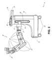
ロボット対応の医療用システムは、特定の処置に応じて様々な方法で構成され得る。図1は、診断及び/又は治療用気管支鏡検査処置のために配置された、カートベースのロボット対応のシステム10の実施形態を示す。気管支鏡検査の間、システム10は、気管支鏡検査のための処置専用気管支鏡であり得る操縦可能な内視鏡13などの医療用器具を、診断及び/又は治療用具を送達するための自然開口部アクセスポイント(すなわち、本実施例ではテーブル上に位置付けされた患者の口)に送達するための1つ又は2つ以上のロボットアーム12を有するカート11を含むことができる。示されるように、カート11は、アクセスポイントへのアクセスを提供するために、患者の上部胴体に近接して位置付けることができる。同様に、ロボットアーム12は、アクセスポイントに対して気管支鏡を位置決めするために作動させることができる。図1の配置はまた、胃腸管(GI)処置を、GI処置のための特殊な内視鏡である胃鏡を用いて行うときに利用することができる。図2は、カートの例示的な実施形態をより詳細に示す。 A. Robotic System - Cart.
Robot-enabled medical systems can be configured in a variety of ways depending on the particular procedure. FIG. 1 shows an embodiment of a cart-based robot-enabled
図1を引き続き参照すると、カート11が適切に位置決めされると、ロボットアーム12は、操縦可能な内視鏡13をロボットで、手動で、又はそれらの組み合わせで患者内に挿入することができる。示されるように、操縦可能な内視鏡13は、内側リーダー部分及び外側シース部分などの少なくとも2つの入れ子式部品を含んでもよく、各部分は、器具ドライバ28の組から別個の器具ドライバに結合され、各器具ドライバは、個々のロボットアームの遠位端に結合されている。リーダー部分をシース部分と同軸上に位置合わせするのを容易にする、器具ドライバ28のこの直線配置は、1つ又は2つ以上のロボットアーム12を異なる角度及び/又は位置に操作することによって空間内に再位置決めされ得る「仮想レール」29を形成する。本明細書に記載される仮想レールは、破線を使用して図に示されており、したがって破線は、システムの物理的構造を示さない。仮想レール29に沿った器具ドライバ28の並進は、外側シース部分に対して内側リーダー部分を入れ子にするか、又は内視鏡13を患者から前進若しくは後退させる。仮想レール29の角度は、臨床用途又は医師の好みに基づいて調整、並進、及び枢動させられてもよい。例えば、気管支鏡検査では、示されるような仮想レール29の角度及び位置は、内視鏡13を患者の口内に曲げ入れることによる摩擦を最小限に抑えながら内視鏡13への医師のアクセスを提供する妥協を表す。Continuing with reference to FIG. 1, once the
内視鏡13は、標的の目的地又は手術部位に到達するまで、ロボットシステムからの正確なコマンドを使用して挿入後に患者の気管及び肺の下流に向けられてもよい。患者の肺網を通したナビゲーションを促進し、及び/又は所望の標的に到達するために、内視鏡13を操縦して、内側リーダー部分を外側シース部分から入れ子状に延ばして、高められた関節運動及びより大きい曲げ半径を得てもよい。別個の器具ドライバ28の使用により、リーダー部分及びシース部分が互いに独立して駆動されることも可能となる。The
例えば、内視鏡13は、例えば、患者の肺内の病変又は小結節などの標的に生検針を送達するように方向付けられてもよい。針は、内視鏡の長さにわたる作業チャネルの下方に展開されて、病理医によって分析される組織サンプルを得てもよい。病理の結果に応じて、追加の生検のために追加のツールが内視鏡の作業チャネルの下流に展開されてもよい。小結節を悪性と識別した後、内視鏡13は、潜在的な癌組織を切除するためにツールを内視鏡的に送達してもよい。場合によっては、診断及び治療的処置は、別の処置で提供することができる。これらの状況において、内視鏡13はまた、標的小結節の場所を「マーク」するために基準を送達するために使用されてもよい。他の例では、診断及び治療的処置は、同じ処置中に送達されてもよい。For example, the
システム10はまた、カート11に支持ケーブルを介して接続されて、カート11への制御、電子機器、流体工学、光学系、センサ、及び/又は電力のためのサポートを提供し得る移動可能なタワー30を含んでもよい。タワー30内にこのような機能を置くことにより、動作を行う医師及びそのスタッフがより容易に調整及び/又は再位置決めすることができるより小さいフォームファクタのカート11が可能となる。追加的に、カート/テーブルと支持タワー30との間の機能の分割は、手術室の乱雑さを低減し、臨床ワークフローの改善を促進する。カート11は患者に近接して位置付けられてもよいが、タワー30は、処置中に邪魔にならないように離れた場所に収容されてもよい。The
上述のロボットシステムをサポートするために、タワー30は、例えば、永続的な磁気記憶ドライブ、ソリッドステートドライブなどの非一時的コンピュータ可読記憶媒体内にコンピュータプログラム命令を記憶するコンピュータベースの制御システムの構成要素を含んでもよい。これらの命令の実行は、実行がタワー30内で行われるのか又はカート11内で行われるのかにかかわらず、システム全体又はそのサブシステムを制御してもよい。例えば、コンピュータシステムのプロセッサによって実行されるとき、命令は、ロボットシステムの構成要素に、関連するキャリッジ及びアームマウントを作動させ、ロボットアームを作動させ、医療用器具を制御させてもよい。例えば、制御信号を受信したことに応答して、ロボットアームの関節内のモータは、アームをある特定の姿勢に位置付けてもよい。To support the robotic system described above, the
タワー30は、内視鏡13を通して展開することができるシステムに、制御された灌注及び吸引機能を提供するために、ポンプ、流量計、弁制御、及び/又は流体アクセスも含むことができる。これらの構成要素はまた、タワー30のコンピュータシステムを使用して制御されてもよい。いくつかの実施形態では、灌注及び吸引能力は、別個のケーブルを介して内視鏡13に直接送達されてもよい。The
タワー30は、フィルタリングされ、保護された電力をカート11に提供するように設計された電圧及びサージ保護具を含んでもよく、それによって、カート11内に電力変圧器及び他の補助電力構成要素を配置することが回避され、カート11はより小さく、より移動可能になる。The
タワー30は、ロボットシステム10全体に展開されたセンサのための支持機器も含んでもよい。例えば、タワー30は、ロボットシステム10を通して光センサ又はカメラから受信したデータを検出、受信、及び処理するためのオプトエレクトロニクス機器を含んでもよい。制御システムと組み合わせて、このようなオプトエレクトロニクス機器は、タワー30内を含むシステム全体に展開された任意の数のコンソール内に表示するためのリアルタイム画像を生成するために使用されてもよい。同様に、タワー30はまた、展開された電磁(electromagnetic、EM)センサから信号を受信し、受信した信号を処理するための電子サブシステムも含んでもよい。タワー30はまた、医療用器具内又は医療用器具上のEMセンサによる検出のためにEM場生成器を収容し、位置付けるためにも使用されてもよい。The
タワー30はまた、システムの残りの部分で利用可能な他のコンソール、例えば、カートの上部に装着されたコンソールに追加して、コンソール31も含んでもよい。コンソール31は、オペレータである医師のためのユーザインターフェース及びタッチスクリーンなどの表示画面を含んでもよい。システム10内のコンソールは、一般に、ロボット制御、並びに内視鏡13のナビゲーション情報及び位置特定情報などの処置の術前及びリアルタイム情報の両方を提供するように設計される。コンソール31が医師に利用可能な唯一のコンソールではない場合、コンソール31は、看護師などの第2のオペレータによって使用されて、患者の健康又はバイタル、及びシステム10の動作を監視するだけでなく、ナビゲーション及び位置特定情報などの処置固有のデータを提供してもよい。その他の実施形態では、コンソール30は、タワー30とは別個の本体内に収容される。The
タワー30は、1つ又は2つ以上のケーブル又は接続部(図示せず)を介してカート11及び内視鏡13に結合されてもよい。いくつかの実施形態では、タワー30からのサポート機能は、単一ケーブルを通してカート11に提供されることにより、手術室を簡略化し、整理整頓することができる。他の実施形態では、特定の機能は、別個の配線及び接続部で結合されてもよい。例えば、単一の電力ケーブルを通してカート11に電力が供給されてもよい一方、制御、光学、流体工学、及び/又はナビゲーションのためのサポートは、別個のケーブルを通して提供されてもよい。The
図2は、図1に示されるカートベースのロボット対応のシステムからのカート11の実施形態の詳細な図を提供する。カート11は、概して、細長い支持構造14(「カラム」と称されることが多い)、カート基部15、及びカラム14の頂部にあるコンソール16を含む。カラム14は、1つ又は2つ以上のロボットアーム12(図2には3つ示されている)の展開を支持するためのキャリッジ17(代替的に「アーム支持体」)などの1つ又は2つ以上のキャリッジを含んでもよい。キャリッジ17は、患者に対してより良好に位置付けるために垂直軸に沿って回転してロボットアーム12の基部を調整する、個別に構成可能なアームマウントを含んでもよい。キャリッジ17はまた、キャリッジ17がカラム14に沿って垂直方向に並進することを可能にするキャリッジインターフェース19を含む。Figure 2 provides a detailed view of an embodiment of a
キャリッジインターフェース19は、キャリッジ17の垂直方向の並進を案内するためにカラム14の両側に位置付けられているスロット20などのスロットを通してカラム14に接続されている。スロット20は、カート基部15に対して様々な垂直方向の高さでキャリッジ17を位置付け、保持するための垂直方向の並進インターフェースを含む。キャリッジ17の垂直方向の並進により、カート11は、様々なテーブルの高さ、患者のサイズ、及び医師の好みを満たすようにロボットアーム12のリーチを調整することが可能となる。同様に、キャリッジ17上の個別に構成可能なアームマウントにより、ロボットアーム12のロボットアーム基部21を様々な構成で角度付けすることが可能となる。The carriage interface 19 is connected to the column 14 through slots, such as
いくつかの実施形態では、キャリッジ17が垂直方向に並進するときにカラム14の内部チャンバ及び垂直方向の並進インターフェース内に汚れ及び流体が侵入するのを防止するために、スロット20には、スロット表面と同一平面及び平行であるスロットカバーが追加されてもよい。スロットカバーは、スロット20の垂直方向の頂部及び底部付近に位置付けされているばねスプールの対を通じて展開されてもよい。カバーは、キャリッジ17が上下に垂直方向に並進するにつれてコイル状から伸縮するように展開されるまで、スプール内でコイル巻きにされている。スプールのばね荷重は、キャリッジ17がスプールに向かって並進するときにカバーをスプール内に後退させるための力を提供し、一方、キャリッジ17がスプールから離れるように並進するときに密封も維持する。カバーは、キャリッジ17が並進するときにカバーが適切に延伸及び後退するのを確実にするために、例えば、キャリッジインターフェース19内のブラケットを使用してキャリッジ17に接続されてもよい。In some embodiments, the
カラム14は、例えば、コンソール16からの入力などのユーザ入力に応答して生成された制御信号に応答してキャリッジ17を機械的に並進させるために垂直方向に位置合わせされた主ねじを使用するように設計された、ギア及びモータなどの機構を内部に含んでもよい。Column 14 may include mechanisms therein, such as gears and motors, designed to use a vertically aligned leadscrew to mechanically translate carriage 17 in response to control signals generated in response to user input, such as input from console 16.
ロボットアーム12は、一般に、一連の関節24によって接続されている一連のリンク23によって分離されたロボットアーム基部21及びエンドエフェクタ22を含んでもよく、各関節は独立したアクチュエータを含み、各アクチュエータは、独立して制御可能なモータを含む。独立して制御可能な各関節は、ロボットアーム12が利用可能な独立した自由度を表す。ロボットアーム12の各々は、7つの関節を有してもよく、したがって、7つの自由度を提供することが可能である。多数の関節は、多数の自由度をもたらし、「冗長」自由度を可能にする。冗長自由度を有することにより、ロボットアーム12は、異なるリンク位置及び関節角度を使用して空間内の特定の位置、向き、及び軌道で、それらのそれぞれのエンドエフェクタ22を位置付けることが可能となる。これにより、システムが空間内の所望のポイントから医療用器具を位置付け、方向付けることが可能になると同時に、医師がアーム関節を患者から離れた臨床的に有利な位置へと移動させて、アームの衝突を回避しながら、よりよいアクセスを生み出すことを可能にする。The
カート基部15は、床の上のカラム14、キャリッジ17、及びロボットアーム12の重量の釣り合いをとる。したがって、カート基部15は、電子機器、モータ、電源、並びにカート11の移動及び/又は固定化のいずれかを可能にする構成要素などの、より重い部品を収容する。例えば、カート基部15は、処置前にカート11が部屋の中をあちこちに容易に移動することを可能にする、転動可能なホイール形状のキャスタ25を含む。適切な位置に到達した後、キャスタ25は、処置中にカート11を所定の場所に保持するためのホイールロックを使用して動かないようにされてもよい。The cart base 15 balances the weight of the column 14, carriage 17, and
カラム14の垂直方向の端部に位置付けられたコンソール16は、ユーザ入力を受信するためのユーザインターフェース及び表示画面(又は、例えば、タッチスクリーン26などの二重目的デバイス)の両方を可能にして、術前データ及び術中データの両方を医師であるユーザに提供する。タッチスクリーン26上の潜在的な術前データは、術前計画、術前コンピュータ断層撮影(computerized tomography、CT)スキャンから導出されたナビゲーション及びマッピングデータ、及び/又は術前の患者への問診からのメモを含んでもよい。ディスプレイ上の術中データは、ツールから提供される光学情報、センサからのセンサ及び座標情報、並びに呼吸、心拍数、及び/又はパルスなどの不可欠な患者統計を含んでもよい。コンソール16は、医師が、カラム14の、キャリッジ17の反対の側からコンソール16にアクセスすることを可能にするように位置付けられ、傾斜が付けられてもよい。この位置から、医師は、コンソール16をカート11の背後から操作しながら、コンソール16、ロボットアーム12、及び患者を見ることができる。示されるように、コンソール16はまた、カート11の操作及び安定化を支援するハンドル27を含む。The console 16 positioned at the vertical end of the column 14 allows for both a user interface and a display screen (or dual-purpose device, e.g., touch screen 26) to receive user input to provide both pre-operative and intra-operative data to the physician user. Potential pre-operative data on the
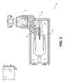
図3は、尿管鏡検査のために配置された、ロボット対応のシステム10の実施形態を示す。尿管鏡検査処置では、カート11は、患者の尿道及び尿管を横断するように設計された処置専用内視鏡である尿管鏡32を患者の下腹部領域に送達するように位置付けられてもよい。尿管鏡検査では、尿管鏡32が患者の尿道と直接位置合わせされて、領域内の敏感な解剖学的構造に対する摩擦及び力を低減することが望ましいことがある。示されるように、カート11は、ロボットアーム12が尿管鏡32を、患者の尿道に直線状に直接アクセスするように位置付けることを可能にするように、テーブルの脚部に位置合わせされてもよい。テーブルの脚部から、ロボットアーム12は、尿道を通して患者の下腹部に直接、仮想レール33に沿って尿管鏡32を挿入してもよい。3 shows an embodiment of the robot-enabled
気管支鏡検査におけるのと同様の制御技法を使用して尿道に挿入した後、尿管鏡32は、診断及び/又は治療用途のために、膀胱、尿管、及び/又は腎臓にナビゲートされてもよい。例えば、尿管鏡32は、尿管及び腎臓に向けられ、尿管鏡32の作動チャネルの下方に展開されたレーザー又は超音波結石破砕デバイスを使用して、形成された腎臓結石を破砕することができる。砕石術が完了した後、結果として得られた結石片は、尿管鏡32の下方に展開されたバスケットを使用して除去されてもよい。After insertion into the urethra using control techniques similar to those in bronchoscopy, the
図4は、血管処置のために同様に配置された、ロボット対応のシステム10の実施形態を示す。血管処置において、システム10は、カート11が、操縦可能なカテーテルなどの医療用器具34を、患者の脚内の大腿動脈内のアクセスポイントに送達することができるように構成され得る。大腿動脈は、ナビゲーションのためのより大きな直径と、患者の心臓への、遠回りが比較的少ない曲がりくねった経路との両方を呈し、これによりナビゲーションが単純化する。尿管鏡検査処置のように、カート11は、患者の脚及び下腹部に向けて位置付けられて、ロボットアーム12が患者の大腿/腰領域内の大腿動脈アクセスポイントへの直接的な線形アクセスで仮想レール35を提供することを可能にしてもよい。動脈内への挿入後、器具ドライバ28を並進させることによって医療用器具34が方向付けられ、挿入されてもよい。代替的に、カートは、例えば、肩及び手首付近の頸動脈及び腕動脈などの代替的な血管アクセスポイントに到達するために、患者の上腹部の周囲に位置付けられてもよい。4 shows an embodiment of a robot-enabled
B.ロボットシステム-テーブル。
ロボット対応の医療用システムの実施形態はまた、患者テーブルを組み込んでもよい。テーブルの組み込みは、カートを除去することによって手術室内の資本設備の量を低減し、患者へのより大きいアクセスを可能にする。図5は、気管支鏡検査処置のために配置された、そのようなロボット対応のシステムの実施形態を示す。システム36は、プラットフォーム38(「テーブル」又は「ベッド」として図示)を床より上に支持するための支持構造体又はカラム37を含む。カートベースのシステムと同様に、システム36のロボットアーム39のエンドエフェクタは、器具ドライバ42の線形アライメントから形成された仮想レール41を通して、又はそれに沿って、図5の気管支鏡40などの細長い医療用器具を操作するように設計された器具ドライバ42を含む。実際には、蛍光透視撮像を提供するためのCアームは、放射器及び検出器をテーブル38の周囲に置くことによって、患者の上部腹部領域の上方に位置付けられてもよい。 B. Robot System - Table.
An embodiment of a robot-enabled medical system may also incorporate a patient table. The incorporation of a table reduces the amount of capital equipment in the operating room by eliminating carts and allows greater access to the patient. FIG. 5 shows an embodiment of such a robot-enabled system deployed for a bronchoscopy procedure. The
図6は、説明を目的として、患者及び医療用器具なしのシステム36の代替的な図を提供する。示されるように、カラム37は、1つ又は2つ以上のロボットアーム39の基部となり得る、システム36内でリング形状として図示される1つ又は2つ以上のキャリッジ43を含んでもよい。キャリッジ43は、カラム37の長さにわたる垂直方向のカラムインターフェース44に沿って並進して、ロボットアーム39が患者に到達するように位置付けられ得る異なるバンテージポイントを提供してもよい。キャリッジ43は、カラム37内に位置付けられている機械的モータを使用してカラム37の周りを回転して、ロボットアーム39が、例えば、患者の両側などのテーブル38の多数の側部へのアクセスを有することを可能にしてもよい。複数のキャリッジを有する実施形態では、キャリッジはカラム上に個別に位置付けられてもよく、他のキャリッジとは独立して並進及び/又は回転してもよい。キャリッジ43はカラム37を取り囲む必要はなく、又は更には円形である必要もないが、図示されるようなリング形状は、構造的バランスを維持しながらカラム37の周りでのキャリッジ43の回転を容易にする。キャリッジ43の回転及び並進により、システム36は、内視鏡及び腹腔鏡などの医療用器具を患者の異なるアクセスポイントに位置合わせすることができる。他の実施形態(図示せず)では、システム36は、並行して延在するバー又はレールの形態の調整可能なアーム支持体を有する患者テーブル又はベッドを含むことができる。1つ又は2つ以上のロボットアーム39を、(例えば、肘関節を有する肩部を介して)垂直方向に調整することができる調整可能なアーム支持体に取り付けることができる。垂直方向の調節を提供することによって、ロボットアーム39は、有利には、患者テーブル又はベッドの下にコンパクトに収容されることが可能であり、その後、処置中に引き上げられることが可能である。6 provides an alternative view of the
ロボットアーム39は、ロボットアーム39に追加の構成可能性を提供するために個別に回転し得る、及び/又は入れ子式に延び得る一連の関節を含むアームマウント45の組を介してキャリッジ43に装着されてもよい。追加的に、アームマウント45は、キャリッジ43が適切に回転されると、アームマウント45がテーブル38の同じ側(図6に示すように)、テーブル38の両側(図9に示すように)、又はテーブル38の隣接する側部(図示せず)のいずれかに位置付けられ得るように、キャリッジ43上に位置付けられ得る。The
カラム37は、テーブル38の支持及びキャリッジ43の垂直方向の並進のための経路を構造的に提供する。内部に、カラム37は、キャリッジの垂直方向の並進を案内するための主ねじ、及び主ねじに基づくキャリッジ43の並進を機械化するためのモータを備えていてもよい。カラム37はまた、キャリッジ43及びその上に装着されたロボットアーム39に電力及び制御信号を伝達してもよい。The
テーブル基部46は、図2に示すカート11のカート基部15と同様の機能を果たし、テーブル/ベッド38、カラム37、キャリッジ43、及びロボットアーム39の釣り合いをとるためにより重い構成要素を収容する。テーブル基部46はまた、処置中に安定性を提供するために剛性キャスタを組み込んでもよい。テーブル基部46の底部から展開されるキャスタは、基部46の両側で反対方向に延在し、システム36を移動させる必要があるときに後退してもよい。The
引き続き図6を参照すると、システム36はまた、テーブルとタワーとの間でシステム36の機能を分割して、テーブルのフォームファクタ及びバルクを低減するタワー(図示せず)を含んでもよい。先に開示された実施形態と同様に、タワーは、処理、計算、及び制御能力、電力、流体工学、並びに/又は光学及びセンサ処理などの様々なサポート機能をテーブルに提供してもよい。タワーはまた、医師のアクセスを改善し、手術室を整理整頓するために、患者から離れて位置付けられるように移動可能であってもよい。追加的に、タワー内に構成要素を配置することにより、ロボットアーム39の潜在的な収容のために、テーブル基部46内により多くの保管空間を可能にする。タワーはまた、キーボード及び/又はペンダントなどのユーザ入力のためのユーザインターフェース、並びにリアルタイム撮像、ナビゲーション、及び追跡情報などの術前及び術中情報のための表示画面(又はタッチスクリーン)の両方を提供するマスターコントローラ又はコンソールも含んでもよい。いくつかの実施形態では、タワーはまた、送気のために使用されるガスタンク用のホルダを含んでもよい。Continuing to refer to FIG. 6, the
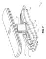
いくつかの実施形態では、テーブル基部は、使用されていないときにロボットアームを収容して格納してもよい。図7は、テーブルベースのシステムの実施形態におけるロボットアームを収容するシステム47を示す。システム47では、キャリッジ48は、ロボットアーム50、アームマウント51、及びキャリッジ48を基部49内に収容するために、基部49内へと垂直方向に並進させられてもよい。基部カバー52は、並進及び後退して、キャリッジ48、アームマウント51、及びロボットアーム50をカラム53の周りに展開させるように開き、使用されていないときにそれらを収容して保護するように閉じられてもよい。基部カバー52は、閉じたときに汚れ及び流体の侵入を防止するために、その開口部の縁部に沿って膜54で封止されてもよい。In some embodiments, the table base may house and store the robot arm when not in use. FIG. 7 shows a system 47 for housing the robot arm in a table-based system embodiment. In the system 47, the
図8は、尿管鏡検査処置のために構成されたロボット対応のテーブルベースシステムの実施形態を示す。尿管鏡検査では、テーブル38は、患者をカラム37及びテーブル基部46からオフアングルに位置付けるためのスイベル部分55を含んでもよい。スイベル部分55は、スイベル部分55の底部をカラム37から離すように位置付けるために、(例えば、患者の頭部の下方に位置する)枢動点を中心に回転又は枢動してもよい。例えば、スイベル部分55の枢動により、Cアーム(図示せず)が、テーブル38の下のカラム(図示せず)と空間を奪い合うことなく、患者の下部腹部の上方に位置付けられることを可能にする。カラム37の周りにキャリッジ35(図示せず)を回転させることにより、ロボットアーム39は、尿道に到達するように、仮想レール57に沿って、患者の鼠径部領域に尿管鏡56を直接挿入してもよい。尿管鏡検査では、処置中に患者の脚の位置を支持し、患者の鼠径部領域への明確なアクセスを可能にするために、テーブル38のスイベル部分55にあぶみ58もまた固定されてもよい。8 shows an embodiment of a robot-enabled table-based system configured for a ureteroscopy procedure. For ureteroscopy, the table 38 may include a swivel portion 55 for positioning the patient off-angle from the
腹腔鏡処置では、患者の腹壁内の小さな切開部を通して、低侵襲性器具を患者の解剖学的構造に挿入してもよい。いくつかの実施形態では、低侵襲性器具は、患者内の解剖学的構造にアクセスするために使用されるシャフトなどの細長い剛性部材を含む。患者の腹腔の膨張後、器具は、把持、切断、アブレーション、縫合などの外科的又は医療的タスクを実施するように指示されてもよい。いくつかの実施形態では、器具は、腹腔鏡などのスコープを含むことができる。図9は、腹腔鏡検査処置のために構成されたロボット対応のテーブルベースのシステムの実施形態を示す。図9に示されるように、システム36のキャリッジ43は回転させて垂直方向に調整されて、器具59が患者の両側の最小切開部を通過して患者の腹腔に到達するようアームマウント45を使用して位置付けられ得るように、ロボットアーム39の対をテーブル38の両側に位置付けてもよい。In a laparoscopic procedure, a minimally invasive instrument may be inserted into the patient's anatomy through a small incision in the patient's abdominal wall. In some embodiments, the minimally invasive instrument includes an elongated rigid member, such as a shaft, that is used to access an anatomical structure within the patient. After distension of the patient's abdominal cavity, the instrument may be directed to perform a surgical or medical task, such as grasping, cutting, ablation, suturing, etc. In some embodiments, the instrument may include a scope, such as a laparoscope. FIG. 9 illustrates an embodiment of a robot-enabled table-based system configured for a laparoscopic procedure. As shown in FIG. 9, the
腹腔鏡処置に対応するために、ロボット対応のテーブルシステムはまた、プラットフォームを所望の角度に傾斜させてもよい。図10は、ピッチ又は傾斜調整を有するロボット対応の医療用システムの実施形態を示す。図10に示されるように、システム36は、テーブル38の傾斜に適応して、テーブルの一方の部分を他方の部分より床から離れた距離に位置決めすることができる。追加的に、アームマウント45は、ロボットアーム39がテーブル38と同じ平面関係を維持するように、傾斜に一致するように回転してもよい。より急な角度に適応するために、カラム37はまた、テーブル38が床に接触するか又はテーブル基部46と衝突するのを防ぐためにカラム37が垂直方向に延在するのを可能にする入れ子部分60を含んでもよい。To accommodate laparoscopic procedures, the robotic table system may also tilt the platform to a desired angle. FIG. 10 shows an embodiment of a robotic medical system with pitch or tilt adjustment. As shown in FIG. 10, the
図11は、テーブル38とカラム37との間のインターフェースの詳細な図を提供する。ピッチ回転機構61は、カラム37に対するテーブル38のピッチ角を多数の自由度で変更するように構成されてもよい。ピッチ回転機構61は、カラム-テーブルインターフェースでの直交軸1、2の位置付けによって可能にされてもよく、各軸は、電気ピッチ角コマンドに応答して別個のモータ3、4によって作動される。一方のねじ5に沿った回転は、一方の軸1における傾斜調整を可能にし、他方のねじ6に沿った回転は、他方の軸2に沿った傾斜調整を可能にする。いくつかの実施形態では、カラム37に対するテーブル38のピッチ角を複数の自由度で変更するために、玉継ぎ手が使用されてもよい。Figure 11 provides a detailed view of the interface between the table 38 and the
例えば、ピッチ調整は、テーブルをトレンデレンブルグ位置に位置付けようとするときに、すなわち下腹部手術のために患者の下腹部を患者の上腹部よりも床からより高い位置に位置決めしようとするときに、特に有用である。トレンデレンブルグ位置は、重力によって患者の内臓を患者の上腹部に向かってスライドさせ、低侵襲性ツールが入って腹腔鏡前立腺切除術などの下腹部の外科又は医療処置を行うために、腹腔を空にする。For example, pitch adjustments are particularly useful when attempting to position the table in the Trendelenburg position, i.e., positioning the patient's lower abdomen higher off the floor than the patient's upper abdomen for lower abdominal surgery. The Trendelenburg position allows gravity to slide the patient's internal organs toward the patient's upper abdomen, emptying the abdominal cavity for entry of minimally invasive tools to perform lower abdominal surgical or medical procedures, such as laparoscopic prostatectomy.
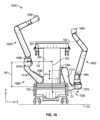
図12及び図13は、テーブルベースの外科用ロボットシステム100の別の実施形態の等角図及び端面図を示す。外科用ロボットシステム100は、テーブル101に対して1つ又は2つ以上のロボットアームを支持するように構成され得る1つ又は2つ以上の調節可能なアーム支持体105(例えば、図14参照)を含む。図示される実施形態では、単一の調整可能なアーム支持体105が示されているが、テーブル101の反対側に追加のアーム支持体を設けることができる。調整可能アームサポート105は、テーブル101に対して移動して、調整可能アーム支持体105及び/又はそれに装着された任意のロボットアームの位置をテーブル101に対して調整及び/又は変更できるように構成され得る。例えば、調整可能なアーム支持体105は、テーブル101に対して1つ又は2つ以上の自由度で調整することができる。調整可能なアーム支持体105は、1つ又は2つ以上の調整可能なアーム支持体105及びそれに取り付けられた任意のロボットアームをテーブル101の下に容易に収容する能力を含む高い汎用性をシステム100に提供する。調整可能なアーム支持体105は、収容位置から、テーブル101の上面の下の位置まで上昇させることができる。他の実施形態では、調整可能なアーム支持体105は、収容位置から、テーブル101の上面の上方の位置まで上昇させることができる。12 and 13 show isometric and end views of another embodiment of a table-based surgical
調節可能なアーム支持体105は、リフト、横方向並進、傾斜などを含む、いくつかの自由度を提供することができる。図12及び図13の図示の実施形態では、アーム支持体105は、4つの自由度で構成され、それらは図12に矢印で示されている。第1の自由度は、z方向における調整可能なアーム支持体105の調整(「Zリフト」)を可能にする。例えば、調整可能なアーム支持体105は、テーブル101を支持するカラム102に沿って、又はそれに対して上下に動くように構成されたキャリッジ109を含むことができる。第2の自由度は、調整可能なアーム支持体105が傾斜することを可能にする。例えば、調整可能なアーム支持体105は、回転接合部を含むことができ、これにより、調整可能なアーム支持体105を、トレンデレンブルグ位置のベッドと位置合わせすることが可能となり得る。第3の自由度は、調整可能なアーム支持体105が「上方枢動する」ことを可能にでき、それを使用して、テーブル101の側部と調整可能なアーム支持体105との間の距離を調整することができる。第4の自由度は、調整可能なアーム支持体105がテーブルの長手方向の長さに沿って並進するのを可能にする。The
図12及び図13の外科用ロボットシステム100は、基部103に装着されたカラム102によって支持されるテーブルを含むことができる。基部103及びカラム102は、支持面に対してテーブル101を支持する。床軸131及び支持軸133は、図13に示される。The surgical
調整可能なアーム支持体105は、カラム102に装着することができる。他の実施形態では、アーム支持体105は、テーブル101又は基部103に装着することができる。調整可能なアーム支持体105は、キャリッジ109、バー又はレールコネクタ111、及びバー又はレール107を含むことができる。いくつかの実施形態では、レール107に装着された1つ又は2つ以上のロボットアームは、互いに対して並進及び移動することができる。The
キャリッジ109は、第1の接合部113によってカラム102に取り付けられてもよく、それにより、キャリッジ109がカラム102に対して移動することが可能になる(例えば、第1又は垂直軸123を上下するなど)。第1の接合部113は、調整可能なアーム支持体105に第1の自由度(「Zリフト」)を提供することができる。調整可能なアーム支持体105は、第2の自由度(傾斜)を調整可能なアーム支持体105に提供する第2の接合部115を含むことができる。調整可能なアーム支持体105は、第3の自由度(「上方枢動」)を調整可能なアーム支持体105に提供することができる第3の接合部117を含むことができる。第3の軸127を中心にしてレールコネクタ111を回転させるときにレール107の向きを維持するように第3の接合部117を機械的に拘束する、追加の接合部119(図13に示す)を設けることができる。調整可能なアーム支持体105は、第4の自由度(並進)を第4の軸129に沿って調整可能なアーム支持体105に提供することができる第4の接合部121を含むことができる。The
図14は、テーブル101の両側に装着された2つの調節可能なアーム支持体105A、105Bを有する、外科用ロボットシステム140Aの端面図を示す。第1のロボットアーム142Aは、第1の調整可能なアーム支持体105Bのバー又はレール107Aに取り付けられる。第1のロボットアーム142Aは、レール107Aに取り付けられた基部144Aを含む。第1のロボットアーム142Aの遠位端は、1つ又は2つ以上のロボット医療用器具又はツールに取り付けることができる器具駆動機構146Aを含む。同様に、第2のロボットアーム142Bは、レール107Bに取り付けられた基部144Bを含む。第2のロボットアーム142Bの遠位端は、器具駆動機構146Bを含む。器具駆動機構146Bは、1つ又は2つ以上のロボット医療用器具又はツールに取り付けるように構成され得る。14 shows an end view of a surgical
いくつかの実施形態では、ロボットアーム142A、142Bのうちの1つ又は2つ以上は、7以上の自由度を有するアームを含む。いくつかの実施形態では、ロボットアーム142A、142Bのうちの1つ又は2つ以上は、挿入軸(挿入を含む1つの自由度)、リスト(リストピッチ、ヨー及びロールを含む3つの自由度)、エルボ(エルボピッチを含む1つの自由度)、ショルダ(ショルダピッチ及びヨーを含む2つの自由度)、及び基部144A、144B(並進を含む1つの自由度)、を含む8自由度を含むことができる。いくつかの実施形態では、挿入自由度は、ロボットアーム142A、142Bによって提供することができるが、他の実施形態では、器具自体は、器具ベースの挿入アーキテクチャを介して挿入を提供する。In some embodiments, one or more of the
C.器具ドライバ及びインターフェース。
システムのロボットアームのエンドエフェクタは、(i)医療用器具を作動させるための電気機械的手段を組み込む器具ドライバ(代替的には、「器具駆動機構」又は「器具デバイスマニピュレータ」と呼ばれる)と、(ii)モータなどの任意の電気機械的構成要素を欠いていてもよい、除去可能な又は取り外し可能な医療用器具と、を含み得る。この二分は、医療処置において使用される医療用器具を滅菌する必要性と、医療用器具の機械組立が複雑でありかつ電子機器の感受性が高いことから高価な資本設備を適切に滅菌することができないこととによって引き起こされ得る。したがって、医療用器具は、医師又は医師のスタッフによる個々の滅菌又は廃棄のために、器具ドライバ(したがってそのシステム)から取り外される、除去される、及び交換されるように設計することができる。対照的に、器具ドライバは交換又は滅菌される必要がなく、保護のために掛け布をすることができる。 C. Instrument Drivers and Interfaces.
The end effector of the robotic arm of the system may include (i) an instrument driver (alternatively called an "instrument drive mechanism" or "instrument device manipulator") that incorporates electromechanical means for actuating the medical instrument, and (ii) a removable or detachable medical instrument, which may lack any electromechanical components such as a motor. This dichotomy may be caused by the need to sterilize the medical instruments used in medical procedures and the inability to adequately sterilize expensive capital equipment due to the complex mechanical assembly of the medical instruments and the sensitivity of the electronics. Thus, the medical instruments may be designed to be detached, removed, and replaced from the instrument driver (and thus the system) for individual sterilization or disposal by the physician or physician's staff. In contrast, the instrument driver does not need to be replaced or sterilized and can be draped for protection.
図15は、例示的な器具ドライバを示す。ロボットアームの遠位端に配置される器具ドライバ62は、駆動シャフト64を介して医療用器具に制御されたトルクを提供するために平行軸を伴って配置された1つ又は2つ以上の駆動ユニット63を含む。各駆動ユニット63は、器具と相互作用するための個々の駆動シャフト64と、モータシャフトの回転を所望のトルクに変換するためのギアヘッド65と、駆動トルクを生成するためのモータ66と、モータシャフトの速度を測定して制御回路にフィードバックを提供するエンコーダ67と、制御信号を受信して駆動ユニットを作動させるための制御回路68と、を含む。各駆動ユニット63は、独立して制御され電動化され、器具ドライバ62は、複数(例えば図15に示すように4つ)の独立した駆動出力を医療用器具に提供することができる。動作中、制御回路68は、制御信号を受信し、モータ66にモータ信号を送信し、エンコーダ67によって測定された結果として得られたモータ速度を所望の速度と比較し、モータ信号を変調して所望のトルクを生成する。15 shows an exemplary instrument driver. The
無菌環境を必要とする処置のために、ロボットシステムは、器具ドライバと医療用器具との間に位置する、滅菌ドレープに接続された滅菌アダプタなどの駆動インターフェースを組み込んでもよい。滅菌アダプタの主な目的は、器具ドライバの駆動シャフトから器具の駆動入力部に角度運動を伝達する一方で、駆動シャフトと駆動入力部との間の物理的分離、したがって無菌性を維持することである。したがって、例示的な滅菌アダプタは、器具ドライバの駆動シャフトと嵌合されることが意図された一連の回転入力部及び出力部と、器具に対する駆動入力部と、を含み得る。滅菌アダプタに接続される滅菌ドレープは、透明又は半透明プラスチックなどの薄い可撓性材料で構成され、器具ドライバ、ロボットアーム、及び(カートベースのシステムにおける)カート又は(テーブルベースのシステムにおける)テーブルなどの資本設備を覆うように設計される。ドレープの使用により、滅菌を必要としない領域(すなわち、非滅菌野)に依然として配置されている間に、資本設備を患者に近接して位置付けることが可能となる。滅菌ドレープの反対側では、医療用器具は、滅菌を必要とする領域(すなわち、滅菌野)において患者とインターフェースしてもよい。For procedures requiring a sterile environment, the robotic system may incorporate a drive interface, such as a sterile adapter connected to a sterile drape, located between the instrument driver and the medical instrument. The primary purpose of the sterile adapter is to transmit angular motion from the drive shaft of the instrument driver to the drive input of the instrument while maintaining physical separation, and therefore sterility, between the drive shaft and the drive input. Thus, an exemplary sterile adapter may include a set of rotational inputs and outputs intended to mate with the drive shaft of the instrument driver and a drive input to the instrument. The sterile drape connected to the sterile adapter is constructed of a thin flexible material, such as a transparent or translucent plastic, and is designed to cover the instrument driver, the robotic arm, and capital equipment, such as a cart (in a cart-based system) or a table (in a table-based system). The use of the drape allows the capital equipment to be positioned in close proximity to the patient while still being located in an area that does not require sterility (i.e., the non-sterile field). On the other side of the sterile drape, the medical instrument may interface with the patient in an area that requires sterility (i.e., the sterile field).
D.医療用器具。
図16は、ペアの器具ドライバを備えた例示的な医療用器具を示す。ロボットシステムと共に使用するために設計された他の器具と同様に、医療用器具70は、細長いシャフト71(又は細長い本体)及び器具基部72を含む。医師による手動相互作用が意図されているその設計により「器具ハンドル」とも称される器具基部72は、一般に、ロボットアーム76の遠位端において器具ドライバ75上の駆動インターフェースを通って延びる駆動出力部74と嵌合するように設計された、回転可能な駆動入力部73、例えば、レセプタクル、プーリー、又はスプールを含んでもよい。物理的に接続、ラッチ、及び/又は連結されると、器具基部72の嵌合された駆動入力部73は、器具ドライバ75における駆動出力部74と回転軸を共有して、駆動出力部74から駆動入力部73へのトルクの伝達を可能とすることができる。いくつかの実施形態では、駆動出力部74は、駆動入力部73上のレセプタクルと嵌合するように設計されたスプラインを含んでもよい。 D. Medical devices.
16 shows an exemplary medical instrument with a paired instrument driver. Similar to other instruments designed for use with a robotic system, the
細長いシャフト71は、例えば、内視鏡におけるような解剖学的開口部若しくは管腔、又は腹腔鏡検査におけるような低侵襲性切開部のいずれかを通して送達されるように設計される。細長いシャフト71は、可撓性(例えば、内視鏡と同様の特性を有する)若しくは剛性(例えば、腹腔鏡と同様の特性を有する)のいずれかであってもよく、又は可撓性部分及び剛性部分の両方のカスタマイズされた組み合わせを含んでもよい。腹腔鏡検査のために設計される場合、剛性の細長いシャフトの遠位端は、少なくとも1つの自由度を有するクレビスから形成された接合されたリストから延在するエンドエフェクタ、及び駆動入力部が器具ドライバ75の駆動出力部74から受信したトルクに応答して回転する際に、腱からの力に基づいて作動され得る、例えば、把持具又ははさみなどの外科用ツール又は医療用器具に接続することができる。内視鏡検査のために設計される場合、可撓性の細長いシャフトの遠位端は、器具ドライバ75の駆動出力部74から受信したトルクに基づいて関節運動及び屈曲され得る操縦可能又は制御可能な屈曲部を含んでもよい。The elongated shaft 71 is designed to be delivered through either an anatomical opening or lumen, such as in an endoscope, or a minimally invasive incision, such as in a laparoscopy. The elongated shaft 71 may be either flexible (e.g., with properties similar to an endoscope) or rigid (e.g., with properties similar to a laparoscope), or may include a customized combination of both flexible and rigid portions. When designed for laparoscopy, the distal end of the rigid elongated shaft may be connected to an end effector extending from a jointed wrist formed from a clevis having at least one degree of freedom, and a surgical tool or medical instrument, such as a grasper or scissors, that may be actuated based on forces from a tendon as the drive input rotates in response to torque received from the
器具ドライバ75からのトルクは、細長いシャフト71に沿った腱を使用して細長いシャフト71の下流に伝達される。プルワイヤなどのこれらの個々の腱は、器具ハンドル72内の個々の駆動入力部73に個別に固定されてもよい。ハンドル72から、腱は、細長いシャフト71に沿って1つ又は2つ以上のプルルーメン(pull lumens)を下って導かれ、細長いシャフト71の遠位部分、又は細長いシャフトの遠位部分のリストに固定される。腹腔鏡、内視鏡、又はハイブリッド処置などの外科処置中、これらの腱は、リスト、把持具、又ははさみなどの遠位に装着されたエンドエフェクタに結合されてもよい。このような構成の下で、駆動入力部73に及ぼされるトルクは、腱に張力を伝達し、それによってエンドエフェクタを何らかの方法で作動させる。いくつかの実施形態では、外科処置中に、腱は、関節を軸の周りで回転させることができ、それによってエンドエフェクタを一方向又は別の方向に移動させる。代替的に、腱は、細長いシャフト71の遠位端で把持具の1つ又は2つ以上のジョーに接続されてもよく、腱からの張力によって把持具は閉鎖される。Torque from the
内視鏡検査では、腱は、接着剤、制御リング、又は他の機械的固定を介して、細長いシャフト71に沿って(例えば、遠位端に)位置付けられている屈曲部又は関節運動部に結合されてもよい。屈曲部の遠位端に固定的に取り付けられる場合、駆動入力部73に及ぼされるトルクは、腱の下流に伝達され、より軟質の屈曲部(関節運動可能部又は関節運動可能領域と呼ばれることがある)を屈曲又は関節運動させる。非屈曲部分に沿って、個々の腱を内視鏡シャフトの壁に沿って(又は内側に)向ける個々のプルルーメンを螺旋状又は渦巻状にして、プルワイヤにおける張力からもたらされる半径方向の力の釣り合いをとることが有利であり得る。これらの間の螺旋及び/又は間隔の角度は、特定の目的のために変更又は設計することができ、よりきつい螺旋は負荷力の下でより少ないシャフト圧縮を示し、一方、より少ない量の螺旋は負荷力の下でより大きなシャフト圧縮をもたらすが、屈曲を制限する。スペクトルのもう一方の端部では、プルルーメンは、細長いシャフト71の長手方向軸に平行に方向付けられて、所望の屈曲部又は関節運動可能部における制御された関節運動を可能にしてもよい。In endoscopy, the tendons may be coupled to a flex or articulating section located along the elongated shaft 71 (e.g., at the distal end) via adhesive, control rings, or other mechanical fixation. When fixedly attached to the distal end of the flex, torque exerted on the
内視鏡検査では、細長いシャフト71は、ロボット処置を支援するいくつかの構成要素を収容する。シャフト71は、シャフト71の遠位端における手術領域に対して外科用ツール(又は医療用器具)を展開する、灌注する、及び/又は吸引するための作業チャネルを含んでもよい。シャフト71は、光学カメラを含んでもよい遠位先端部の光学アセンブリとの間で信号を送受信するために、ワイヤ及び/又は光ファイバも収容してもよい。シャフト71はまた、発光ダイオードなどの近位に位置する光源からシャフト71の遠位端に光を搬送するための光ファイバを収容してもよい。In endoscopy, the elongated shaft 71 houses several components that aid in the robotic procedure. The shaft 71 may include a working channel for deploying surgical tools (or medical instruments), irrigating, and/or aspirating the surgical field at the distal end of the shaft 71. The shaft 71 may also house wires and/or optical fibers for transmitting signals to and from an optical assembly at the distal tip, which may include an optical camera. The shaft 71 may also house optical fibers for carrying light from a proximally located light source, such as a light emitting diode, to the distal end of the shaft 71.
器具70の遠位端では、遠位先端部は、診断及び/又は治療、灌注、及び吸引のためにツールを手術部位に送達するための作業チャネルの開口部を含んでもよい。遠位先端部はまた、内部解剖学的空間の画像をキャプチャするために、ファイバスコープ又はデジタルカメラなどのカメラのためのポートを含んでもよい。関連して、遠位先端部はまた、カメラを使用する場合に解剖学的空間を照明するための光源用のポートを含んでもよい。At the distal end of the
図16の例では、駆動シャフト軸、すなわち駆動入力軸は、細長いシャフト71の軸に直交する。しかしながら、この配置は、細長いシャフト71のロール能力を複雑にする。駆動入力部73を静止させながら、細長いシャフト71をその軸に沿ってロールさせることの結果として、腱が駆動入力部73から延在出して細長いシャフト71内のプルルーメンに入るときに、腱の望ましくない絡まりをもたらす。そのような腱の結果としての絡まりは、内視鏡処置中の可撓性の細長いシャフト71の動きを予測することを意図した制御アルゴリズムを妨害する可能性がある。16, the drive shaft axis, i.e., the drive input axis, is orthogonal to the axis of the elongated shaft 71. However, this arrangement complicates the ability of the elongated shaft 71 to roll. Rolling the elongated shaft 71 along its axis while holding the
図17は、駆動ユニットの軸が器具の細長いシャフトの軸に平行である、器具ドライバ及び器具の代替的な設計を示す。示されるように、円形の器具ドライバ80は、ロボットアーム82の端部において平行に位置合わせされた駆動出力部81を備える4つの駆動ユニットを含む。駆動ユニット及びそれらのそれぞれの駆動出力部81は、アセンブリ83内の駆動ユニットのうちの1つによって駆動される器具ドライバ80の回転アセンブリ83内に収容される。回転駆動ユニットによって提供されるトルクに応答して、回転アセンブリ83は、回転アセンブリ83を器具ドライバ80の非回転部分84に接続する円形ベアリングに沿って回転する。電力及び制御信号は、ブラシ付きスリップリング接続(図示せず)による回転を通して維持され得る電気接点を介して、器具ドライバ80の非回転部分84から回転アセンブリ83に伝達されてもよい。他の実施形態では、回転アセンブリ83は、非回転可能部分84に一体化され、したがって他の駆動ユニットと平行ではない別個の駆動ユニットに応答してもよい。回転機構83は、器具ドライバ80が、器具ドライバ軸85周りの単一ユニットとして、駆動ユニット及びそれらのそれぞれの駆動出力部81を回転させることを可能にする。17 shows an alternative design of the instrument driver and instrument, in which the axis of the drive unit is parallel to the axis of the elongated shaft of the instrument. As shown, the
先に開示した実施形態と同様に、器具86は、細長いシャフト部分88と、器具ドライバ80内の駆動出力部81を受け入れるように構成された複数の駆動入力部89(レセプタクル、プーリー、及びスプールなど)を含む器具基部87(説明目的のために透明な外部スキンで示される)と、を含んでもよい。先の開示された実施形態とは異なり、器具シャフト88は、器具基部87の中心から延在し、軸は駆動入力部89の軸に実質的に平行であり、図16の設計にあるように直交してはいない。Similar to the previously disclosed embodiment, the
器具ドライバ80の回転アセンブリ83に結合されると、器具基部87及び器具シャフト88を含む医療用器具86は、器具ドライバ軸85を中心にして回転アセンブリ83と一緒に回転する。器具シャフト88は器具基部87の中心に位置決めされているため、器具シャフト88は、取り付けられたときに器具ドライバ軸85と同軸である。したがって、回転アセンブリ83の回転により、器具シャフト88は、それ自体の長手方向軸を中心に回転する。更に、器具基部87が器具シャフト88と共に回転すると、器具基部87内の駆動入力部89に接続された任意の腱は、回転中に絡まらない。したがって、駆動出力部81、駆動入力部89、及び器具シャフト88の軸の平行性は、どの制御腱も絡めることなくシャフト回転を可能にする。When coupled to the rotating
図18は、いくつかの実施形態による、器具ベースの挿入アーキテクチャを有する器具を示す。器具150は、上述の器具ドライバのいずれかに連結することができる。器具150は、細長いシャフト152と、シャフト152に接続されたエンドエフェクタ162と、シャフト152に連結されたハンドル170と、を含む。細長いシャフト152は、近位部分154及び遠位部分156を有する管状部材を含む。細長いシャフト152は、その外側表面に沿った1つ又は2つ以上のチャネル又は溝158を含む。溝158は、1つ又は2つ以上のワイヤ又はケーブル180を内部を通して受け入れるように構成されている。したがって、1つ又は2つ以上のケーブル180は、細長いシャフト152の外側表面に沿って延びる。他の実施形態では、ケーブル180は、細長いシャフト152を通って延びることもできる。ケーブル180のうちの1つ又は2つ以上の操作(例えば、器具ドライバを介して)により、エンドエフェクタ162の作動がもたらされる。18 illustrates an instrument having an instrument-based insertion architecture, according to some embodiments. The
器具基部とも称され得る器具ハンドル170は、一般に、器具ドライバの取り付け面上で1つ又は2つ以上のトルクカプラと往復嵌合するように設計された1つ又は2つ以上の機械的入力部174、例えば、レセプタクル、プーリー又はスプールを有する取り付けインターフェース172を含むことができる。いくつかの実施形態では、器具150は、細長いシャフト152がハンドル170に対して並進することを可能にする一連のプーリー又はケーブルを含む。換言すれば、器具150自体は器具の挿入に適応する器具ベースの挿入アーキテクチャを含み、それによって器具150の挿入を提供するためのロボットアームへの依存を最小化する。他の実施形態では、ロボットアームは、器具の挿入に大きく関与することができる。The instrument handle 170, which may also be referred to as the instrument base, may generally include a mounting
E.コントローラ。
本明細書に記載の任意のロボットシステムは、ロボットアームに取り付けられた器具を操作するための入力デバイス又はコントローラを含むことができる。いくつかの実施形態では、コントローラは、器具と連結(例えば、通信的に、電子的に、電気的に、無線的に、及び/又は機械的に)することができ、それによりコントローラの操作は、例えば、マスタースレーブ制御を介して、器具の対応する操作を引き起こす。 E. Controller.
Any of the robotic systems described herein can include an input device or controller for manipulating an instrument attached to the robotic arm. In some embodiments, the controller can be coupled (e.g., communicatively, electronically, electrically, wirelessly, and/or mechanically) to the instrument such that manipulation of the controller causes a corresponding manipulation of the instrument, e.g., via master-slave control.
図19は、コントローラ182の実施形態の斜視図である。本実施形態では、コントローラ182は、インピーダンス制御及びアドミタンス制御の両方を有することができるハイブリッドコントローラを含む。他の実施形態では、コントローラ182は、インピーダンス又は受動的制御だけを利用することができる。他の実施形態では、コントローラ182は、アドミタンス制御だけを利用することができる。ハイブリッドコントローラであることにより、コントローラ182は、有利には、使用中、より低い知覚慣性を有することができる。FIG. 19 is a perspective view of an embodiment of the
図示される実施形態では、コントローラ182は、2つの医療用器具の操作を可能にするように構成され、2つのハンドル184を含む。ハンドル184の各々は、ジンバル186に接続されている。各ジンバル186は、位置決めプラットフォーム188に接続されている。In the illustrated embodiment, the
図19に示されるように、各位置決めプラットフォーム188は、プリズム接合部196によってカラム194に連結されたSCARAアーム(selective compliance assembly robot arm)198を含む。プリズム接合部196は、(例えば、レール197に沿って)カラム194に沿って並進して、ハンドル184の各々がz方向に並進され、第1の自由度を提供するように構成されている。SCARAアーム198は、x-y平面におけるハンドル184の動作を可能にし、2つの更なる自由度を提供するように構成されている。As shown in FIG. 19, each
いくつかの実施形態では、1つ又は2つ以上のロードセルがコントローラ内に位置付けられる。例えば、いくつかの実施形態では、ロードセル(図示せず)は、ジンバル186の各々の本体内に位置付けられる。ロードセルを設けることによって、コントローラ182の一部分は、アドミタンス制御下で動作することができ、それによって、使用中にコントローラの知覚慣性を有利に低減する。いくつかの実施形態では、位置決めプラットフォーム188はアドミタンス制御用に構成され、一方、ジンバル186はインピーダンス制御用に構成されている。他の実施形態では、ジンバル186はアドミタンス制御用に構成され、位置決めプラットフォーム188はインピーダンス制御用に構成されている。したがって、いくつかの実施形態では、位置決めプラットフォーム188の並進又は位置自由度は、アドミタンス制御に依存することができ、一方、ジンバル186の回転自由度はインピーダンス制御に依存する。In some embodiments, one or more load cells are positioned within the controller. For example, in some embodiments, a load cell (not shown) is positioned within the body of each of the
F.ナビゲーション及び制御。
従来の内視鏡検査は、オペレータである医師に腔内誘導を提供するために、蛍光透視法(例えば、Cアームを通して送達され得るような)、及び他の形態の放射線ベースの撮像モダリティの使用を伴うことがある。対照的に、本開示によって企図されるロボットシステムは、放射線への医師の曝露を低減し、手術室内の機器の量を低減するために、非放射線ベースのナビゲーション及び位置特定手段を提供することができる。本明細書で使用するとき、「位置特定」という用語は、基準座標系内の対象物の位置を判定及び/又は監視することを指すことがある。術前マッピング、コンピュータビジョン、リアルタイムEM追跡、及びロボットコマンドデータなどの技術は、放射線を含まない動作環境を達成するために個別に又は組み合わせて使用されてもよい。放射線ベースの撮像モダリティが依然として使用されるその他の場合、術前マッピング、コンピュータビジョン、リアルタイムEM追跡、及びロボットコマンドデータは、放射線ベースの撮像モダリティによってのみ取得される情報を改善するために、個別に又は組み合わせて使用されてもよい。 F. Navigation and Control.
Traditional endoscopy may involve the use of fluoroscopy (e.g., as may be delivered through a C-arm) and other forms of radiation-based imaging modalities to provide intraluminal guidance to the operator-physician. In contrast, the robotic system contemplated by the present disclosure may provide non-radiation-based navigation and localization means to reduce the physician's exposure to radiation and reduce the amount of equipment in the operating room. As used herein, the term "localization" may refer to determining and/or monitoring the position of an object in a reference coordinate system. Techniques such as pre-operative mapping, computer vision, real-time EM tracking, and robot command data may be used individually or in combination to achieve a radiation-free operating environment. In other cases where radiation-based imaging modalities are still used, pre-operative mapping, computer vision, real-time EM tracking, and robot command data may be used individually or in combination to improve on the information obtained solely by radiation-based imaging modalities.
図20は、例示的な実施形態による、器具の場所など、ロボットシステムの1つ又は2つ以上の要素の位置を推定する位置特定システム90を示すブロック図である。位置特定システム90は、1つ又は2つ以上の命令を実行するように構成されている1つ又は2つ以上のコンピュータデバイスのセットであってもよい。コンピュータデバイスは、上で考察された1つ又は2つ以上の構成要素内のプロセッサ(又は複数のプロセッサ)及びコンピュータ可読メモリによって具現化されてもよい。例として、限定するものではないが、コンピュータデバイスは、図1に示されるタワー30内にあってもよく、図1~図4に示されるカート11内にあってもよく、図5~図14に示されるベッド内にあってもよい。20 is a block diagram illustrating a
図20に示されるように、位置特定システム90は、入力データ91~94を処理して医療用器具の遠位先端部の位置データ96を生成する位置特定モジュール95を含んでもよい。位置データ96は、基準系に対する器具の遠位端の位置及び/又は向きを表すデータ又は論理であってもよい。基準系は、患者の解剖学的構造、又はEM場生成器(EM場生成器についての以下の説明を参照)などの既知の対象物に対する基準系とすることができる。20, the
ここで、様々な入力データ91~94についてより詳細に説明する。術前マッピングは、低用量CTスキャンの収集を使用して達成することができる。術前CTスキャンは、例えば、患者の内部解剖学的構造の切欠き図の「スライス」として可視化される三次元画像へと再構成される。全体として分析される場合、患者の肺網などの患者の解剖学的構造の解剖学的空腔、空間、及び構造のための画像ベースのモデルが生成され得る。中心線形状(center-line geometry)などの手法をCT画像から決定及び近似して、モデルデータ91(術前CTスキャンのみを使用して生成された場合は「術前モデルデータ」とも称される)と称される患者の解剖学的構造の三次元ボリュームを作成することができる。中心線形状の使用は、米国特許出願第14/523,760号で考察されており、その内容はその全体が本明細書に組み込まれる。ネットワーク位相モデルもまた、CT画像から導出されてもよく、気管支鏡検査に特に適している。The various input data 91-94 will now be described in more detail. Pre-operative mapping can be accomplished using acquisition of low-dose CT scans. The pre-operative CT scans are reconstructed into three-dimensional images that are visualized, for example, as cutaway "slices" of the patient's internal anatomy. When analyzed as a whole, an image-based model can be generated for the anatomical cavities, spaces, and structures of the patient's anatomy, such as the patient's pulmonary network. Techniques such as center-line geometry can be determined and approximated from the CT images to create a three-dimensional volume of the patient's anatomy, referred to as model data 91 (also referred to as "pre-operative model data" when generated using only pre-operative CT scans). The use of center-line geometry is discussed in U.S. Patent Application Serial No. 14/523,760, the contents of which are incorporated herein in their entirety. Network phase models may also be derived from CT images and are particularly suited for bronchoscopy.
いくつかの実施形態では、器具はカメラを装備して、視覚データ(又は画像データ)92を提供してもよい。位置特定モジュール95は、視覚データ92を処理して、1つ又は2つ以上の視覚ベースの(又は画像ベースの)位置追跡モジュール又は機能を有効にしてもよい。例えば、術前モデルデータ91は、医療用器具(例えば、内視鏡又は内視鏡の作業チャネルを通って前進する器具)のコンピュータビジョンベースの追跡を可能にするために、視覚データ92と共に使用されてもよい。例えば、術前モデルデータ91を使用して、ロボットシステムは、内視鏡の予想される移動経路に基づいて、モデルから、予測される内視鏡画像のライブラリを生成することができ、各画像はモデル内の位置にリンクされる。手術中に、このライブラリは、カメラ(例えば、内視鏡の遠位端でのカメラ)でキャプチャされたリアルタイム画像を画像ライブラリ内のものと比較して、位置特定を支援するために、ロボットシステムによって参照することができる。In some embodiments, the instrument may be equipped with a camera to provide visual data (or image data) 92. The
他のコンピュータビジョンベースの追跡技術は、特徴追跡を使用して、カメラ、したがって内視鏡の動作を判定する。位置特定モジュール95のいくつかの特徴は、解剖学的管腔に対応する術前モデルデータ91内の円形幾何学形状を特定し、どの解剖学的管腔が選択されたか、並びにカメラの相対的な回転及び/又は並進運動を決定するために、それらの幾何学的形状の変化を追跡してもよい。位相マップの使用は、視覚ベースのアルゴリズム又は技術を更に向上させることがある。Other computer vision based tracking techniques use feature tracking to determine the motion of the camera, and therefore the endoscope. Some features of the
光学フロー、別のコンピュータビジョンベースの技術は、カメラの移動を推測するために、視覚データ92内のビデオシーケンス内の画像ピクセルの変位及び並進を分析してもよい。光学フロー技術の例としては、動作検出、オブジェクトセグメンテーション計算、輝度、動作補償符号化、立体視差測定などを挙げることができる。複数の反復にわたり多数のフレームを比較することにより、カメラ(及びしたがって内視鏡)の移動及び位置を判定することができる。Optical flow, another computer vision based technique, may analyze the displacement and translation of image pixels in a video sequence in the
位置特定モジュール95は、リアルタイムEM追跡を使用して、術前モデルによって表される患者の解剖学的構造に登録され得るグローバル座標系内に、内視鏡のリアルタイムの位置を生成することができる。EM追跡では、医療用器具(例えば、内視鏡器具)内の1つ又は2つ以上の位置及び向きに埋め込まれた1つ又は2つ以上のセンサコイルを含むEMセンサ(又はトラッカー)は、既知の位置に配置された1つ又は2つ以上の静的EM場発生器によって生成されるEM場の変動を測定する。EMセンサによって検出された位置情報は、EMデータ93として記憶される。EM場発生器(又は送信機)は、埋め込まれたセンサが検出し得る低強度磁場を生成するために、患者に近接して配置することができる。磁場はEMセンサのセンサコイル内に小さい電流を誘導し、EMセンサとEM場発生器との間の距離及び角度を判定するためにこの電流が分析され得る。これらの距離及び向きは、患者の解剖学的構造の術前モデル内の位置と座標系内の単一の場所を位置合わせする幾何学的変換を判定するために、患者の解剖学的構造(例えば、術前モデル)に術中「登録」され得る。一旦登録されると、医療用器具の1つ又は2つ以上の位置(例えば、内視鏡の遠位先端部)に埋め込まれたEMトラッカは、患者の解剖学的構造を通る医療用器具の進行のリアルタイム表示を提供することができる。The
ロボットコマンド及び運動学データ94はまた、ロボットシステムのための位置特定データ96を提供するために、位置特定モジュール95によって使用されてもよい。関節運動コマンドから生じるデバイスピッチ及びヨーは、術前較正中に判定され得る。術中、これらの較正測定値は、既知の挿入深度情報と組み合わせて使用されて、器具の位置を推定し得る。代替的に、これらの計算は、EM、視覚、及び/又は位相モデリングと組み合わせて分析して、ネットワーク内の医療用器具の位置を推定し得る。The robotic commands and
図20が示すように、いくつかの他の入力データは、位置特定モジュール95によって使用することができる。例えば、図20には示していないが、形状感知ファイバを利用する器具は、位置特定モジュール95が器具の位置及び形状を判定するために使用し得る形状データを提供することができる。As FIG. 20 illustrates, several other input data can be used by the
位置特定モジュール95は、入力データ91~94を組み合わせて使用することができる。場合によっては、このような組み合わせは、位置特定モジュール95が入力データ91~94の各々から判定された場所に信頼重み(confidence weight)を割り当てる確率的アプローチを使用し得る。したがって、EMデータが信頼でき得ない場合(EM干渉が存在する場合など)、EMデータ93によって判定された位置の信頼性を低下させることができ、位置特定モジュール95は、視覚データ92並びに/又はロボットコマンド及び運動学データ94により重く依存してもよい。The
上で考察されるように、本明細書で考察されるロボットシステムは、上述の技術のうちの1つ又は2つ以上の組み合わせを組み込むように設計することができる。タワー、ベッド、及び/又はカートをベースとするロボットシステムのコンピュータベースの制御システムは、例えば、永続的な磁気記憶ドライブ、ソリッドステートドライブなどの非一時的コンピュータ可読記憶媒体内に、コンピュータプログラム命令を記憶してもよく、コンピュータプログラム命令は、実行されると、システムに、センサデータ及びユーザコマンドを受信及び分析させ、システム全体の制御信号を生成させ、グローバル座標系内の器具の位置、解剖学的マップなどのナビゲーション及び位置特定データを表示させる。As discussed above, the robotic systems discussed herein can be designed to incorporate one or a combination of two or more of the above-mentioned techniques. The computer-based control system of the tower, bed, and/or cart-based robotic system may store, for example, in a non-transitory computer-readable storage medium, such as a persistent magnetic storage drive, solid-state drive, etc., computer program instructions that, when executed, cause the system to receive and analyze sensor data and user commands, generate system-wide control signals, and display navigation and localization data, such as instrument position within a global coordinate system, anatomical maps, etc.
2.ロボット医療用システムのための検体コレクタ
図1~図20などを参照して上述したものなどのロボット医療用システムは、患者から対象物、検体、又は試料を取り出すことを伴うロボット医療処置に使用することができる。例えば、ロボット医療用システムを使用して、腎臓結石除去手順を実行することができる。ロボット腎臓結石除去処置の間、医師は、コントローラを使用して、様々なロボット医療用器具(例えば、上記の内視鏡及び腹腔鏡など)を操作することができる。ロボット医療用器具は、器具を位置付けて操作するロボットマニピュレータ(ロボットアーム、ロボット駆動デバイス、及びロボット器具駆動機構など)と係合させることができる。 2. Specimen Collector for Robotic Medical Systems Robotic medical systems, such as those described above with reference to Figures 1-20, etc., can be used for robotic medical procedures that involve removing an object, specimen, or sample from a patient. For example, a robotic medical system can be used to perform a kidney stone removal procedure. During a robotic kidney stone removal procedure, a physician can use a controller to manipulate various robotic medical instruments (such as the endoscopes and laparoscopes described above). The robotic medical instruments can be engaged with robotic manipulators (such as robotic arms, robotic drive devices, and robotic instrument drive mechanisms) that position and manipulate the instruments.
例として、ロボット医療用システムは、尿管鏡腎臓結石除去処置中に使用するように構成されている3つのロボットアームを含むことができる。第1のロボットアームは、ロボット尿管鏡及びバスケットデバイス(の例えば制御関節運動)を操作し、制御することができる。第2のロボットアーム上に位置付けられた遠位駆動デバイスは、尿管鏡を患者に挿入し、患者の外へと後退させることができる。いくつかの実施形態では、第3のロボットアームを任意選択で使用して、経皮的に挿入されたロボット腹腔鏡を制御することができる(例えば、経皮的に支援された尿管鏡検査(percutaneously assisted ureteroscopy、PAU)中に)。医師は、バスケットデバイスで腎臓結石を捕捉するようにシステムを制御することができる。次いで、ロボット尿管鏡が結石を保持しているとき、ロボット尿管鏡を後退させて、患者から結石を取り出すことができる。患者の身体の外側に位置付けたら、結石を解放するためにバスケットデバイスを開くことができる。次いで、ロボット尿管鏡を身体に再挿入して、必要に応じて更なる結石を取り出すことができる。一般に、処置後に分析するために、結石は保持される。As an example, a robotic medical system can include three robotic arms configured for use during a ureteroscopic kidney stone removal procedure. A first robotic arm can manipulate and control (e.g., control articulation of) a robotic ureteroscope and a basket device. A distal drive device positioned on a second robotic arm can insert the ureteroscope into a patient and retract it out of the patient. In some embodiments, a third robotic arm can optionally be used to control a percutaneously inserted robotic laparoscope (e.g., during percutaneously assisted ureteroscopy (PAU)). A physician can control the system to capture a kidney stone with the basket device. Then, when the robotic ureteroscope is holding the stone, the robotic ureteroscope can be retracted to remove the stone from the patient. Once positioned outside the patient's body, the basket device can be opened to release the stone. The robotic ureteroscope can then be reinserted into the body to remove additional stones as needed. Typically, the stone is retained for analysis after the procedure.
本開示は、患者から対象物、検体、又は試料を取り出すことを伴うロボット医療処置を容易にするために、ロボット医療用システムと共に使用するように構成されている検体コレクタに関する。検体コレクタは、ロボット医療用システムがロボットでその中に検体を堆積できるように構成することができ、これにより手動又は物理的な相互作用を最小限に抑えることができる。手動による対象物の除去処置(例えば、手動による腎臓結石の除去)では、患者から除去された対象物は手動で検体カップに入れられ、一般に手術室で医師又は他の無菌ユーザが物理的に保持する。そのような手動式の検体カップの使用は、臨床医が保持するか又は特別に設計されたホルダを有することが必要なためコストが増加する及び/又はロボット化率が低下するという理由から、ロボット医療用システムでの使用には不利であり得る。The present disclosure relates to a specimen collector configured for use with a robotic medical system to facilitate a robotic medical procedure involving removal of an object, specimen, or sample from a patient. The specimen collector may be configured to allow the robotic medical system to robotically deposit a specimen therein, thereby minimizing manual or physical interaction. In a manual object removal procedure (e.g., manual kidney stone removal), the object removed from the patient is manually placed in a specimen cup, typically physically held by a physician or other sterile user in an operating room. The use of such manual specimen cups may be disadvantageous for use with a robotic medical system because of the increased cost and/or decreased roboticity due to the need for a clinician to hold or have a specially designed holder.
以下でより詳細に説明されるように、本明細書に記載の検体コレクタは、ロボット処置を容易にし、かつ/又はそれを最適化するように、ロボット医療用システムと共に使用するために具体的に構成することができる。例えば、本明細書に記載の検体コレクタは、ロボット制御された医療用器具がその中に検体を迅速かつ効率的に堆積させることができる位置において、ロボット医療用システムの構成要素に統合され、かつ/又は支持されるように構成することができる。最初の例として、ロボット医療用システムと共に使用するために構成された検体コレクタは、システムの様々なロボット構成要素を覆うように構成されている滅菌ドレープに統合することができる。検体コレクタは、ドレープが設置されたときに有利に位置付けられるように、ドレープ上に位置付けることができる。例えば、検体コレクタは、バスケットデバイスが患者から後退されたときにロボット制御されたバスケットデバイスの真下にある位置に位置付けることができる。この位置において、バスケットデバイスは単に開いて、回収した対象物を検体コレクタ内に落下させることができる。検体コレクタは、その中に堆積された対象物を保持しつつ、流体をそこを通って排出することを可能にする少なくとも1つの多孔質部分で構成することができる。検体コレクタは、対象物を中に堆積させるために大きな面積が存在するように、検体コレクタの開口を保持するように構成されている開口保持デバイス(例えば、柔軟なワイヤ又は金属ストリップ)で構成することができる。更に、検体コレクタは、ドレープを除去する(例えば、引き裂く)ことができるように構成することができるため、対象物を分析のために容易に送ることができる。いくつかの実施形態では、ドレープ上に検体コレクタを含めることにより、有意な利益を提供する費用効果の高いソリューションが提供される。As described in more detail below, the specimen collectors described herein can be specifically configured for use with a robotic medical system to facilitate and/or optimize a robotic procedure. For example, the specimen collectors described herein can be configured to be integrated and/or supported by components of a robotic medical system in a location where a robotically controlled medical instrument can rapidly and efficiently deposit specimens therein. As a first example, a specimen collector configured for use with a robotic medical system can be integrated into a sterile drape configured to cover various robotic components of the system. The specimen collector can be positioned on the drape such that it is advantageously positioned when the drape is installed. For example, the specimen collector can be positioned in a position directly beneath a robotically controlled basket device when the basket device is retracted from the patient. In this position, the basket device can simply open and allow the collected objects to fall into the specimen collector. The specimen collector can be configured with at least one porous portion that allows fluid to drain therethrough while retaining objects deposited therein. The specimen collector can be configured with an aperture retention device (e.g., a flexible wire or metal strip) configured to hold the aperture of the specimen collector such that a large area is present for depositing the object therein. Additionally, the specimen collector can be configured to allow the drape to be removed (e.g., torn away) so that the object can be easily delivered for analysis. In some embodiments, the inclusion of the specimen collector on the drape provides a cost-effective solution that provides significant benefits.
これら及び他の特徴は、本明細書に記載の検体コレクタの特定の例示的な特徴及び態様を示すことを意図している、図に示される実施形態を参照して以下でより詳細に説明される。例示される実施形態は限定することを意図するものではなく、当業者は、本開示を考慮すると、本開示の範囲内である様々な修正を行うことができることを理解するであろう。These and other features are described in more detail below with reference to the embodiments illustrated in the figures, which are intended to illustrate certain exemplary features and aspects of the specimen collectors described herein. The illustrated embodiments are not intended to be limiting, and those skilled in the art will understand, upon consideration of this disclosure, that various modifications may be made that are within the scope of the present disclosure.
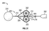
図21及び図22は、検体コレクタ300を含むロボット医療用システム200の実施形態の上面図及び側面図をそれぞれ示す。検体コレクタ300は、患者202内から回収された検体が、ロボットシステム200を使用してその中に堆積され得るように構成されている。図示の実施形態では、システム200は、いくつかある構成要素の中でも特に、医療用器具204、ロボットマニピュレータ(例えば、駆動デバイス206)、滅菌バリア208(図22に示されるような)、及び検体コレクタ300を備える。21 and 22 show top and side views, respectively, of an embodiment of a robotic
図示の実施形態では、医療用器具204は、図3を参照して上述した尿管鏡32と同様であり得るロボット対応の尿管鏡を備える。他の実施形態では、医療用器具204は、図1~図20を参照して上述した医療用器具のいずれか、並びに内視鏡、腹腔鏡、及びカテーテルを含む、他のタイプの医療用器具を備えることができる。図21及び図22の実施形態に示されるように、医療用器具204は、器具基部210及び細長いシャフト212を含むことができる。図示の実施形態では、細長いシャフト212の近位端は、器具基部210から延びている。いくつかの実施形態では、細長いシャフト212は、可撓性シャフト及び/又は関節運動シャフトを含む。In the illustrated embodiment, the
細長いシャフト212の遠位端214は、患者202に挿入されるように構成されている。例えば、ロボットマニピュレータ(例えば、以下により詳細に説明される駆動デバイス206)は、細長いシャフト212の遠位端214を患者202に挿入し、患者202から後退させることができるように、細長いシャフト212の挿入及び/又は後退を駆動するように構成され得る。図示の実施形態では、医療用器具204は、細長いシャフト212の遠位端214が患者202から後退された位置に示されている。The
図示した実施形態では、システム200はアクセスシース216を含む。アクセスシース216は、患者202に挿入されて、医療用器具204の細長いシャフト212が挿入され得るチャネル又は導管を提供することができる。図示の実施形態では、アクセスシース216は、患者202の尿道に挿入された尿管アクセスシースであるが、他の自然の患者の開口又は他の外科用ポート(例えば、腹腔鏡ポート)に挿入され得る他のタイプのアクセスシースも使用することができる。いくつかの実施形態では、アクセスシース216は、チューブを備える。In the illustrated embodiment, the
医療用器具204は、患者内から検体を捕捉(例えば、把持、掴持、保持など)するように構成することができる。例えば、腎臓結石除去処置の場合、医療用器具204は、腎臓結石を患者202から取り出すことができるように、腎臓結石を捕捉するように構成されているバスケットデバイスを含むことができる。上述のように、いくつかの実施形態では、バスケットデバイスは、医療用器具204の細長いシャフト212の作業チャネルを通して挿入することができる(ロボット及び/又は手動で制御可能な)ツールとして構成することができる。いくつかの実施形態では、バスケットデバイスは、医療用器具204内に直接統合される。本明細書に記載の例は、腎臓結石の除去に関するが、医療用器具204は、患者202内の他のタイプの対象物、検体、又は試料を収集及び回収するように構成することができる。例えば、いくつかの実施形態では、医療用器具204は、患者202から生検試料をとるように構成される。The
図21及び図22に示されるロボット医療用システム200では、ロボット器具204を動作させるための様々なロボットマニピュレータが示されている。図示の実施形態では、システム200は、駆動デバイス206、器具駆動機構228、及びロボットアーム226として構成されているロボットマニピュレータを含む。器具駆動機構228及びロボットアーム226は、図22の側面図で見ることができる。これらのロボットマニピュレータは、前述のように及び以下でより詳細に説明されるように、様々な方法で医療用器具204と係合させることができる。In the robotic
図示の実施形態では、駆動デバイス206は、医療用器具204の細長いシャフト212と係合し、細長いシャフト212の遠位先端部214の患者202の内外への軸方向運動(例えば、挿入及び/又は後退)を駆動するように構成されている。例えば、図21に示すように、駆動デバイス206は、細長いシャフト212と係合するか、又は接触することができるローラ222を含む。いくつかの実施形態では、ローラ222は、ローラ222と細長いシャフト212との間に把持を提供する変形可能な材料を含むことができる。いくつかの実施形態では、材料は、シリコーンゴムを含む。図示した実施形態では、ローラ222が回転すると、細長いシャフト212は、駆動デバイス206を通って又は駆動デバイス206に対して軸方向に引っ張られる、押される、又は別様に駆動され得る。ローラ222を第1の方向に回転させることにより、細長いシャフト212の挿入を引き起こし、ローラ222を第2の反対方向に回転させることにより、細長いシャフト212の後退を引き起こすことができる。いくつかの実施形態では、ローラ222の代わりに又はローラ222に加えて、他の駆動機構を使用することができる。図示の実施形態では、細長いシャフト212は、駆動デバイス206のチャネル224の中を通る。チャネル224は、閉鎖チャネル及び/又は開放チャネルを含むことができる。開放チャネル224を使用することにより、医療用器具204の細長いシャフト212を駆動デバイス206に装填することを容易にすることができ、これにより、デバイスの使用を単純化し、動作時間を短縮することができる。例えば、開放チャネルは、医療用器具204を患者内から完全に後退させる必要なしに、医療従事者などのユーザが医療用器具204の調整を手動で行うことができるように、術中又は医療処置中の医療用器具204の装填及び/又は取り外しを容易にすることができる。In the illustrated embodiment, the
図22に示されるように、駆動デバイス206は、ロボットアーム226に取り付ける、装着する、又は別様に接続することができる。ロボットアーム226は、器具駆動機構228を含むことができ、駆動デバイス206を器具駆動機構228に取り付けることができる。器具駆動機構228は、駆動デバイス206を作動させるために、駆動デバイス206上の対応する駆動入力部と係合して作動させるように構成されている駆動出力部を含むことができる。図示の実施形態では、滅菌アダプタ230は、駆動デバイス206が滅菌アダプタ230を通って器具駆動機構228と係合するように、器具駆動機構228と駆動デバイス206との間に位置付けられる。滅菌アダプタ230は、器具駆動機構228の駆動出力部と駆動デバイス206上の対応する駆動入力部との間を結合するように、又は別様にそれらの間で運動を伝達するように構成され得る。更に、滅菌アダプタ230は、以下でより詳細に説明するように、(図22に最もよく見られるように)滅菌バリア208の一部分を画定又は提供するように構成され得る。As shown in FIG. 22, the
引き続き図22を参照すると、駆動デバイス206が装着されているロボットアーム226は、空間内の駆動デバイス206の位置を操作するように移動するように構成することができる。いくつかの実施形態では、例えば、図示されるように、駆動デバイス206を、アクセスシース216に近接して位置付けることができる。細長いシャフト212が挿入される点に近接して(例えば、アクセスシース216の近くに)駆動デバイス206を位置付けることで、細長いシャフト212の座屈を低減することができる。Continuing to refer to FIG. 22, the
システム200の図示された実施形態は、医療用器具204の細長いシャフト212の軸方向運動を駆動するための駆動デバイス206を含み、他のタイプのロボットマニピュレータを使用して、他の実施形態で軸方向運動を駆動することができる。例えば、いくつかの実施形態では、軸方向運動は、医療用器具204の基部210が取り付けられているロボットアーム226を移動させることによって駆動される。他の実施形態では、医療用器具204の基部210は、例えば、図18を参照して上述したように、細長いシャフトの軸方向運動を駆動するように構成されている。While the illustrated embodiment of the
図22に示すように、医療用器具204の基部210はまた、ロボットマニピュレータと係合され得る。図示の実施形態では、基部210は、第2のロボットアーム226上に位置決めされた第2の器具駆動機構228と係合される。図示されるように、別の滅菌アダプタ230は、器具基部210と器具駆動機構228との間に位置付けることができる。基部210と係合された器具駆動機構228は、器具駆動機構228の駆動出力部が、医療用器具204の基部210上の対応する駆動入力部を駆動して、例えば、細長いシャフト212の関節運動及び/又はバスケットデバイスの関節運動、開放、及び/又は閉鎖を制御するように構成され得る。器具基部210と器具駆動機構228との間の係合は、例えば、図15~図17を参照して上述されている。22, the
ロボットアーム226は、例えば、図1~図4に示されるようにカートに装着された、又はそこから延在するロボットアーム、及び/又は図5~図14に示されるように患者プラットフォーム又はテーブルから延在するロボットアームであり得る。ロボットアーム226の遠位端上に位置付けられ得る例示的な器具駆動機構228は、図16~図18に示されている。The
図22は、ロボット医療用システム200が滅菌バリア208を含むことができることを示している。滅菌バリア208は、非滅菌野から滅菌野を分離するように構成することができる。図示の実施形態では、滅菌バリア208は、前述の1つ又は2つ以上の滅菌ドレープ232及び滅菌アダプタ230によって提供される。滅菌ドレープ232は、非滅菌野内に位置付けられているロボット医療用システム200の構成要素を覆うサイズ及び形状に構成されている可撓性シート(例えば、プラスチックシート)を備えることができる。図示されるように、滅菌ドレープ232は、ロボットアーム226及び器具駆動機構228を覆う。滅菌ドレープのより詳細な例を図29~図31に示し、これを以下でより詳細に説明する。FIG. 22 shows that the robotic
図22に示すように、ロボット医療用システム200のいくつかの構成要素は、滅菌野内に位置付けられ、他の構成要素は、非滅菌野内に位置付けられる。例えば、図示の実施形態では、医療用器具204、駆動デバイス206、アクセスシース216、及び患者202は、滅菌野内に位置付けられ、一方、ロボットアーム226及び器具駆動機構228は、非滅菌野に位置付けられる。他の構成も可能である。As shown in FIG. 22, some components of the robotic
上記のように、システム200はまた、医療用器具204を使用して患者202から取り出された検体を中に堆積させることができる検体コレクタ300を含む。図22の側面図で最もよく見られるように、検体コレクタ300は、レセプタクル部分302及びコネクタ304を含むことができる。レセプタクル部分302は、検体を中に堆積させることができるレセプタクル、容器、管、又はリポジトリを提供するように構成され、コネクタ304は、レセプタクル部分302をロボット医療用システム200の構成要素に取り付けて、検体コレクタ300を支持及び位置決めするように構成されている。コネクタ304は、レセプタクル部分302に結合することができる。いくつかの実施形態では、レセプタクル部分302は、レセプタクル又は容器を作り出すように形成されたプラスチックシートなどの可撓性材料から作製される。いくつかの実施形態では、レセプタクル部分302は可撓性バッグを備える。レセプタクル部分302は、その中に検体を堆積させることができる開口部を含む。いくつかの実施形態では、検体コレクタ300は、レセプタクル部分302の開口部を位置決めし、その中に検体を堆積しやすくするために開口部を開放構成に保持するように構成されている開口保持デバイスを更に備える。レセプタクル部分302及びコネクタ304の様々な特徴及び実施形態について、以下でより詳細に説明する。検体コレクタ300のより詳細な図が、図26~図27に示されている。As noted above, the
図22に示すように、検体コレクタ300は、滅菌野内に位置付けられ得る。例えば、図示の実施形態では、検体コレクタ300のコネクタ304は、駆動デバイス206が接続されるロボットアーム226を覆う滅菌ドレープ232に取り付けられる。検体コレクタ300の他の場所も可能である。例えば、いくつかの実施形態では、コネクタ304は、検体コレクタ300を、滅菌アダプタ230に、アクセスシース216に、又は駆動デバイス206若しくは器具駆動機構228自体に取り付ける。22, the
図21及び図22はまた、いくつかの実施形態において、検体コレクタ300は、中に検体が堆積しやすいように、ロボットシステム200上に有利に位置決めされ得ることを示す。図示の実施形態では、検体コレクタ300は、遠位先端部214が患者202及び/又はアクセスシース216から引き抜かれるときに、医療用器具204の細長いシャフト212の遠位先端部214の下方(例えば、直下)の位置に位置付けられている。この配置では、検体をレセプタクル部分302内に堆積させることは、検体を解放し(例えば、バスケットデバイスを開く)、検体を重力によってレセプタクル部分302内に落下させることを可能にすることによって達成することができる。検体コレクタ300のこの配置はまた、細長いシャフト212とアクセスシース216との間の位置合わせを維持することができ、それにより、検体がレセプタクル部分302内に堆積された後、細長いシャフト212の遠位先端部214を、患者202に迅速に再挿入して、処置を継続することができる。これは、処置の全体的な長さを短縮し、患者の転帰を改善することができる。21 and 22 also illustrate that in some embodiments, the
更に、図21及び図22に示すように、いくつかの実施形態では、検体コレクタ300は、患者(例えば、アクセスシース216)内へのアクセスに近接している位置においてロボットシステム200上に有利に位置決めされ得る。図示の実施形態では、例えば、検体コレクタ300は、駆動デバイス206の遠位(すなわち、患者に面する)側に位置決めされる。この配置は、医療用器具204の遠位先端部214を検体コレクタ300上に位置決めするのに必要な動きの量を有益に最小限に抑えることができる。この場合も、処置の全体的な長さを短縮することができる。更に、ロボットアーム226は、医療用器具204の遠位先端部214を検体コレクタ300上に位置決めするのに必要な運動の量を更に最小化するために、患者202へのアクセスに近接して駆動デバイス206を位置決めすることができる。例えば、図22に示すように、駆動デバイス206の遠位側は、検体コレクタがアクセスシース216のすぐ近位に位置決めされるように、アクセスシース216の近位側に近接して位置する。21 and 22, in some embodiments, the
図22に示されるように(また、図26及び図27を参照して以下でより詳細に説明されるように)、コネクタ304は、取り付けタブを備えることができる。レセプタクル部分302は、取り付けタブから延在することができる。すなわち、レセプタクル部分302は、取り付けタブに取り付けることができる。取り付けタブは、検体コレクタ300を支持するロボット医療用システム200の構成要素に取り付けるように構成することができる。例えば、取り付けタブは、滅菌ドレープ232、滅菌アダプタ230、駆動デバイス206、アクセスシース216、又はロボット医療用システム200の他の構成要素に取り付けるように構成することができる。22 (and described in more detail below with reference to FIGS. 26 and 27), the
上記のように、図示の実施形態では、コネクタ304は、滅菌ドレープ232に取り付けられる。いくつかの実施形態では、コネクタ304は、滅菌ドレープ232に固定的に又は恒久的に取り付けられる。すなわち、いくつかの実施形態では、検体コレクタ300は、滅菌ドレープ232の構成要素である。これらの実施形態では、検体コレクタ300は、ドレープ232がロボット医療用システム200の上に設置されたときに、検体コレクタ300が上述のように有利に又は所望の位置に位置決めされるように、ドレープ232上に位置付けることができる。他の実施形態では、コネクタ304は、滅菌ドレープ232(又はロボット医療用システム200の他の構成要素)に選択的に取り付けるように構成することができる。例えば、コネクタ304は、取り付けタブ上に接着ストリップを備えることができる。次いで、ユーザは、接着ストリップを使用して、必要に応じて、検体コレクタ300をロボット医療用システム200の構成要素に取り付けることができる。As noted above, in the illustrated embodiment, the
レセプタクル部分302は、レセプタクル部分302がコネクタ304から取り外され得るように、取り外し可能な方法で取り付けタブ又はコネクタ304に取り付けられることができる。いくつかの実施形態では、検体がレセプタクル部分302内に堆積されると、レセプタクル部分302は、検体をその中に保持しながらコネクタ304から取り外すことができる。次いで、レセプタクル部分302を、検体の分析のために送ることができる。以下に記載されるように、いくつかの実施形態では、検体コレクタ300は、取り付けタブ又はコネクタ304と、レセプタクル部分302が取り付けタブ又はコネクタ304から引き裂かれ得るように構成されているレセプタクル部分302との間に穿孔を含む。以下に説明するように、コネクタ304からレセプタクル部分302を取り外すための他の方法もまた可能である。The
いくつかの実施形態では、レセプタクル部分302の少なくとも一部分は多孔性であり、検体を保持しながら、流体がレセプタクル部分302から排出されることを可能にするように構成されている。一部の医療処置中、処置中に使用される灌漑薬又は患者流体などの流体は、レセプタクル部分302内に入り込むことができる。レセプタクル部分302の多孔質部分は、この流体を排出することを可能にすることができる。いくつかの実施形態では、検体コレクタ300は、レセプタクル部分302からそのような流体を能動的に又は受動的に収集することができる流体システムに接続することができる排水ポートを含むことができる。多孔質部分の多孔性は、収集された検体がレセプタクル部分内に保持されている間、流体が多孔質部分を通って排出されるように構成することができる。In some embodiments, at least a portion of the
図23は、器具駆動機構228が上に位置決めされたロボットアーム226の遠位端の斜視図である。図示の実施形態では、ロボットアーム226は、滅菌ドレープ232で覆われている。図示されるように、滅菌ドレープ232は、器具駆動機構228の上に嵌合するように構成されている滅菌アダプタ230を含む滅菌バリアの一部であり得る。滅菌アダプタ230は、滅菌ドレープ232と係合するように構成され得るカラー234を有することができ、滅菌アダプタ230は、器具駆動機構228とそれに取り付けられた構成要素(器具基部210又は駆動デバイス206など)との間に滅菌インターフェースを提供することができる。23 is a perspective view of the distal end of the
図23はまた、滅菌ドレープ232に取り付けられた検体コレクタ300の実施形態を示す。いくつかの実施形態では、検体コレクタ300は、カラー234において滅菌ドレープ232に取り付けることができる。図23に示す実施形態では、検体コレクタ300は、可撓性バッグとして構成されている。FIG. 23 also illustrates an embodiment of a
図24は、ロボット医療用システム200の例示的な制御構成要素のブロック図である。図示される実施形態では、制御構成要素は、プロセッサ240、メモリ242、及びコントローラ244を含む。メモリ242は、ロボット医療用システム200の態様を制御するために様々な機能を実行するようにプロセッサ240を構成する命令を含むことができる。例えば、メモリ242は、実行されると、図25を参照して以下に説明される機能を実行するようにプロセッサ240を構成する命令を含むことができる。医師又は他のオペレータは、コントローラ244を使用して、ロボット医療用システム200を制御するための入力を提供することができる。いくつかの実施形態では、コントローラ244は、1つ又は2つ以上のジョイスティック、ボタン、又は他のユーザ入力部を含むハンドヘルドコントローラである。いくつかの実施形態では、コントローラ244は、図19を参照して上述したコントローラであり得る。24 is a block diagram of exemplary control components of the robotic
図25は、ロボット医療用システム200を動作させるために図24の制御構成要素を使用して実行され得る例示的な制御方法248を示すフローチャートである。制御方法は、例えば、命令としてメモリ242に記憶させることができる。方法248は、ブロック250において開始することができ、そこで、命令は、医療用器具204の遠位端214の患者202への挿入を制御するようにプロセッサ240を構成する。いくつかの実施形態では、挿入は、コントローラ244を使用して医師によって命令され、かつ/又は別様に制御される。上記のように、挿入は、様々な方法で提供され得る。例えば、図21及び図22に示される実施形態を参照すると、駆動デバイス206は、ローラ222を使用して挿入を駆動することができる。他の実施形態では、挿入は、ロボットアーム226を使用して医療用器具204を移動させることによって、及び/又は、例えば図18を参照して説明するように、器具ベースの挿入アーキテクチャを使用して器具基部210に対する細長いシャフト212の挿入を駆動することによって、実現することができる。いくつかの実施形態では、挿入は、アクセスシース216を通して提供される。25 is a flow chart illustrating an
ブロック252において、方法248は、医療用器具204を使用して患者202内から検体を収集することを含み得る。いくつかの実施形態では、医師は、コントローラ244を使用して患者202内の医療用器具204の遠位先端部214をナビゲートし、制御することができるので、医師が、試料を位置特定し、収集することを可能にする。上記のように、腎臓結石除去処置の場合、試料を収集することは、医療用器具204の細長いシャフト212の作業チャネルを通して挿入されたバスケットデバイス内の腎臓結石を捕捉することを含み得る。At
試料が収集された状態で、方法248はブロック254に移り、そこでは、遠位端214及び収集された試料が患者202から後退される。後退は、例えば、コントローラ244を使用して医師によって命令され得る。後退は、挿入に関して上述したものと同じ機構を使用してもたらすことができる。例えば、後退は、ロボットアーム226を移動させることによって、及び/又は器具基部210に対する細長いシャフト212の引き戻しを駆動する器具ベースの挿入アーキテクチャを用いて、駆動デバイス206によって駆動することができる。ブロック254において、医療用器具204の遠位先端部214は、検体が検体コレクタ300内に堆積され得る位置に後退させることができる。例えば、遠位先端部214は、図21及び図22に示されるように、検体コレクタ300の上の位置に後退させることができる。いくつかの実施形態では、この堆積位置への後退は、単一のユーザコマンドによってトリガされ得る。例えば、検体が捕捉されると、ユーザは、コントローラ244に単一の入力を提供することができ、これにより、システム200は遠位先端部214を堆積位置に自動的に後退させることができる。With the sample collected, the
ブロック256において、方法248は、検体を試料コレクタ300のレセプタクル部分302内に堆積させることを含み得る。システム200の図示された実施形態では、検体を検体コレクタ300のレセプタクル部分302内に堆積させることは、検体が、重力の下、検体コレクタ300のレセプタクル部分302内に落ちるように、検体を医療用器具204の遠位先端部214から解放することを含み得る。他の実施形態では、堆積は、医療用器具204の細長いシャフト212を関節運動させて、検体を検体コレクタ300に挿入することによって達成することができる。いくつかの実施形態では、検体を検体コレクタ300に堆積させることは、コントローラ244を用いて提供される堆積コマンドを受信した後に自動的に生じ得る。例えば、コマンドの受信時に、システム200は自動的に医療用器具204の遠位端214を堆積位置に移動させ、検体を検体コレクタ300のレセプタクル部分302内にロボットで堆積させることができる。いくつかの実施形態では、システム200は、検体コレクタ300への移動及びその中への堆積が、システム200によって自動的に実行され得る(例えば、ユーザコマンドの受信時に自動的に行われ得る)ように、検体コレクタ300の位置を認識している。すなわち、いくつかの実施形態では、医師は、遠位端214を検体コレクタ300にナビゲートする必要はない。代わりに、そのようなナビゲーションは自動的に起こり得る。At
図26及び図27は、それぞれ、検体コレクタ300の実施形態の正面分解図及び斜視分解図である。図示の実施形態では、検体コレクタ300は、患者から取り出された検体を受容するように構成されたレセプタクル部分302と、レセプタクル部分302に結合され、かつ医療用システムに対してレセプタクル部分302を位置決めするように医療用システムに(例えば、ドレープなどのその構成要素に)取り付けられるように構成されたコネクタ304とを備えている。多孔質部分は、レセプタクル部分302の少なくとも一部分に含まれ得る。多孔質部分は、レセプタクル部分302内に堆積された検体を保持しながら、液体がレセプタクル部分302から排出されることを可能にするように構成することができる。26 and 27 are front and perspective exploded views, respectively, of an embodiment of a
図27の分解図に最もよく示されるように、検体コレクタ300は、第1の層312及び第2の層314を備えることができる。いくつかの実施形態では、第1の層312及び第2の層314の各々は、検体コレクタ300が可撓性バッグのような構造を備えるように、プラスチックシートなどの可撓性層を備えることができる。レセプタクル部分302は、第1の層312と第2の層314との間に形成することができる。例えば、第1の層312は、第1の上縁部312A、第1の右縁部312B、第1の左縁部312C、及び第1の下縁部312Dを備えることができ、第2の層314は、第2の上縁部314A、第2の右縁部314B、第2の左縁部314C、及び第2の下縁部314Dを含むことができる。第2の右縁部314B、第2の左縁部314C、及び第2の下縁部314Dは、第1の可撓性層312及び第2の可撓性層314が、第1の上縁部312Aと第2の上縁部314Aによって(例えば、その間に)画定された開口部を有するポケットを形成するように、それぞれ第1の右縁部312B、第1の左縁部312C、及び第1の下縁部312Dに接続することができる。As best shown in the exploded view of FIG. 27, the
コネクタ304は、第1の層312の、第1の上縁部312Aから延在する部分によって形成された取り付けタブを備えることができる。図26及び図27に示されるように、コネクタ304は、切り欠き316を含むことができる。切り欠き316は、コネクタ304が取り付けることができる構成要素に対応するサイズ及び形状に構成することができる。例えば、図示の実施形態では、切り欠き316は、カラー234(図23)及び/又は器具駆動機構228又は滅菌アダプタ230(図21及び図22)の略円形の形状に対応するように半円形である。コネクタ304上の切り欠き316の他の形状及び構成も可能である。いくつかの実施形態では、切り欠き316は省略可能である。The
いくつかの実施形態では、コネクタ304又は取り付けタブは、検体コレクタ300がその構造の構成要素であるように、滅菌ドレープ232又は滅菌アダプタ230などの別の構造に恒久的に接続され得る。コネクタ304は、その構造がロボットシステム上に設置されたときに、検体コレクタ300が所望の位置に有利に位置付けられるように、その構造に接続することができる。他の実施形態では、コネクタ304又は取り付けタブは、ロボットシステムに選択的に取り付けるように構成されている。例えば、コネクタ304又は取り付けタブは、検体コレクタ300が所望の場所においてロボット医療用システム200に接着によって取り付けることができるように、その少なくとも第1の側に接着性バッキングを含むことができる。In some embodiments, the
図26及び図27に示されるように、第1の層312上では、コネクタ304は、穿孔部分318でレセプタクル部分302に取り付けることができる。すなわち、穿孔318は、レセプタクル部分302とコネクタ306との間に位置決めすることができる。穿孔は、上述のように、レセプタクル部分302をコネクタ306から引き裂くことができるように構成することができる。いくつかの実施形態では、レセプタクル部分302をコネクタ304から取り外し可能に構成するための他の方法が可能である。例えば、穿孔318は、ティアストリップ又は他の好適な構造で置き換えることができる。26 and 27, on the
検体コレクタ300はまた、開口保持デバイス320を含むことができる。開口保持デバイス320は、レセプタクル部分302への検体の堆積を容易にするために、レセプタクル部分302の開口を開放構成で保持するように構成することができる。いくつかの実施形態では、例えば、図示されるように、開口保持デバイス320は、レセプタクル部分302の開口に位置決めすることができる。図示の実施形態では、開口保持デバイス320は、形成可能な金属ストリップ322を備える。図示の実施形態では、形成可能な金属ストリップ322は、取り付けパッド324を用いて第1の層312に対して第1の側に取り付けられ、取り付けパッド324を用いて第2の層314に対して第2の側に取り付けられている。形成可能な金属ストリップ322は、レセプタクル部分302の開口を保持する構成に曲げることができる。開口に埋め込むことができる形成可能な形状保持ワイヤなど、開口保持デバイス320のための他の機構も可能である。いくつかの実施形態では、開口保持デバイス320は、省略することができる。The
上記のように、検体コレクタ300は、流体がレセプタクル部分302から排出されることを可能にするための多孔質部分を含むことができる。いくつかの実施形態では、第1の層312及び第2の層314の一方又は両方は、多孔質であり得る。いくつかの実施形態では、第1の層312及び第2の層314の一方又は両方の一部分は、多孔質であり得る。As described above, the
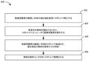
図28は、検体コレクタ300に検体を堆積させるために、ロボット医療用システム200などのロボット医療用システムを使用するための例示的な方法400を示すフローチャートである。方法400は、ブロック402において開始することができ、このブロックは、医療用器具204の細長い本体212の遠位端214を患者202にロボットで挿入することを含む。いくつかの実施形態では、ロボットマニピュレータは、医療用器具の細長い本体と係合し、その挿入及び後退を駆動するように構成されている上述の駆動デバイス206を備える。挿入は、駆動デバイス206によって駆動され得る。いくつかの実施形態では、ロボットマニピュレータは、ロボットアーム226と、ロボットアーム226の遠位端に位置決めされた器具駆動機構228と、を備える。器具駆動機構228は、医療用器具204の基部210に取り付けられて、医療用器具204を動作させるように構成され得る。いくつかの実施形態では、医療用器具の細長い本体212をロボットで挿入することは、ロボットアーム226を動かすことを含む。いくつかの実施形態では、医療用器具204の細長い本体212をロボットで挿入することは、器具駆動機構228を用いて基部210の挿入機構を駆動して、細長い本体212を基部210に対して挿入させることを含む。28 is a flow chart illustrating an
ブロック404において、方法400は、患者内の検体を捕捉するためにロボットマニピュレータで医療用器具204を操作することを含む。いくつかの実施形態では、医療用器具204の基部210は、器具駆動機構228の駆動出力部が基部210内の駆動入力部を作動させて、細長いシャフト212の関節運動を引き起こすように、器具駆動機構228と係合される。医師又は他のオペレータは、細長いシャフト212の関節運動並びに/又は挿入及び後退を制御して、医療用器具204の遠位端214を用いて検体を捕捉することができる。患者内のナビゲーションは、図20を参照して上述したナビゲーション及び位置特定システムによって容易にすることができる。At
ブロック406において、方法400は、医療用器具204の細長いシャフト212をロボットで後退させ、遠位端214及び検体を患者から引き抜くことを含む。いくつかの実施形態では、ロボットマニピュレータは、医療用器具204の細長い本体212と係合し、その挿入及び後退を駆動するように構成されている駆動デバイス206を備える。後退は、駆動デバイス206によって駆動され得る。いくつかの実施形態では、ロボットマニピュレータは、ロボットアーム226と、ロボットアーム226の遠位端に位置決めされた器具駆動機構228と、を備える。器具駆動機構228は、医療用器具204の基部210に取り付けられて、医療用器具204を動作させるように構成され得る。いくつかの実施形態では、医療用器具204の細長いシャフト212をロボットで後退させることは、ロボットアーム226を動かすことを含む。いくつかの実施形態では、医療用器具204の細長い本体212をロボットで後退させることは、器具駆動機構228を用いて基部210の後退機構を駆動して、細長いシャフト212を基部210に対して後退させることを含む。At
ブロック408において、方法400は、検体を検体コレクタ300内にロボットで堆積させることを含む。図21及び図22を参照して説明したように、検体を検体コレクタ300内に堆積させることは、検体を検体コレクタ300の上に位置決付け、検体が検体コレクタ300内に落ちるように検体を解放することを含み得る。いくつかの実施形態では、検体を検体コレクタ内にロボットで堆積させることは、ユーザコマンドの受信時に、細長いシャフト212の遠位端214を、検体コレクタ300に対する堆積位置に自動的に移動させることを含む。At
方法400はまた、少なくとも医療用器具204及び検体コレクタ300を含む滅菌野を少なくともロボットマニピュレータを含む非滅菌野から分離するために、滅菌バリア232をロボット医療用システムに掛けることを含み得る。いくつかの実施形態では、検体コレクタ300は、医療用器具が検体をロボットで堆積させることができる場所において滅菌バリア232に取り付けられる。The
いくつかの実施形態では、方法400はまた、検体コレクタ300を滅菌バリア232に接着によって取り付けることを含む。いくつかの実施形態では、検体コレクタ300のレセプタクル部分302は、コネクタ304から取り外し可能であり、方法400は、レセプタクル部分302をコネクタ304から分離させることを更に含む。方法400は、検体をレセプタクル部分302内に保持しながら、レセプタクル部分302の多孔質部分を通して流体を排出することを更に含み得る。いくつかの実施形態では、方法400はまた、検体コレクタ300の開口保持デバイス320を使用して、検体コレクタの開口を開放位置に位置決めすることを含む。In some embodiments, the
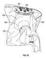
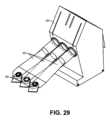
図29は、検体コレクタ300を含む滅菌ドレープ232の実施形態の等角図を示す。滅菌ドレープ232は、図21及び図22に示されるように、滅菌アダプタ230も含み得る滅菌バリア208の一部を形成することができる。滅菌ドレープ232は、プラスチックシートなどの無菌の可撓性材料から作製することができる。図示の実施形態では、滅菌ドレープ232は、例えば、図2及び図30に示されるように3つのロボットアームを含むロボット医療用システムのカートに掛けるように構成されている。示されるように、滅菌ドレープ232は、3つの可撓性チューブ253を含む。3つの可撓性チューブ253は、3つのロボットアームをぴったりと覆うサイズ及び形状に構成されている。可撓性チューブ253は、カートをぴったりと覆うサイズ及び形状に構成されているカートカバー部分254から延在する。29 shows an isometric view of an embodiment of a
図示の実施形態では、検体コレクタ300は、ドレープ232が設置されたときに(上記のように)有利な位置に位置決めされるように、可撓性チューブ253の各々の遠位端に位置決めされる。図30は、3つのロボットアーム226を含むカート上に設置された滅菌ドレープ232の実施形態の斜視図である。図示の実施形態では、ロボットアーム226は、ドレープ232の設置を容易にすることができる例示的なドレープ位置内に移動されている。ドレープ232が設置されると、ロボットアーム226は、医療処置のために適所に移動することができる。In the illustrated embodiment, a
図31は、検体コレクタ300を含む滅菌ドレープ232の別の実施形態を示す。図31のドレープ232は、バー又はレール260に移動可能に装着されたロボットアーム226を含むロボット医療用システムと共に使用するように構成されている。そのようなシステムは、図12~図14を参照して上述され、説明される。この実施形態では、ドレープ232は、ロボットアーム226に掛けるように構成されている3つの可撓性チューブ253と、レール260に掛けるように構成されているレールドレープ部分256と、を含む。示されるように、検体コレクタ300は、可撓性チューブ253の遠位端に位置決めすることができる。FIG. 31 illustrates another embodiment of a
図32は、滅菌ドレープ232、滅菌アダプタ230、及び検体コレクタ300を含むアセンブリとして構成されている滅菌バリア208の実施形態を示す。滅菌アダプタ230は、上部プレート540、下部プレート550、及び滅菌アダプタ230内に回転可能に支持されているトルクカプラ520を含み、これらは、上部及び下部プレート540、550に対してそれらのそれぞれの駆動軸を中心に回転可能となっている。滅菌アダプタ230は、滅菌アダプタ230を器具駆動機構228に固定することができる取り付け機構570(例えば、クリップ、ラッチ、磁石など)を含む。滅菌アダプタ230内の取り付け機構570及び/又はトルクカプラ520は、器具駆動機構228上の対応する特徴と整列することができ、検体コレクタ300は、滅菌バリアをロボットシステムに固定する際にロボットアームが検体コレクタ300を検体採取に有利な位置に保持することができ、ユーザが検体コレクタ300を手動で位置決めする必要がないように、滅菌アダプタ230に対して既知の位置又は定位置で滅菌バリア208に取り付けられることができる。例えば、図32に示すように、滅菌アダプタは、トルクカプラ520のセット及び取り付け機構570の位置に基づいて、遠位側515及び近位側525を画定することができる。検体コレクタ300は、滅菌アダプタ230の遠位側515上の滅菌に取り付けることができる。そのような位置により、遠位側から延在する医療用機器(例えば、尿管鏡及びバスケットツール)は、検体を抽出し、患者の身体から後退する際に、遠位側515の検体コレクタ内に検体を容易に堆積させることができる。32 illustrates an embodiment of the
3.実装システム及び用語
本明細書に開示される実装態様は、ロボット医療用システムと共に使用するように構成されている検体コレクタのためのシステム、方法、及び装置を提供する。 3. Implementation Systems and Terminology Implementations disclosed herein provide systems, methods, and devices for a specimen collector configured for use with a robotic medical system.
本明細書で使用するとき、「結合する」、「結合している」、「結合された」という用語、又は結合という単語の他の変形は、間接的接続又は直接的接続のいずれかを示し得ることに留意されたい。例えば、第1の構成要素が第2の構成要素に「結合される」場合、第1の構成要素は、別の構成要素を介して第2の構成要素に間接的に接続される、又は第2の構成要素に直接的に接続される、のいずれかであってもよい。It should be noted that, as used herein, the terms "couple," "coupled," "coupled," or other variations of the word coupled, may indicate either an indirect connection or a direct connection. For example, when a first component is "coupled" to a second component, the first component may be either indirectly connected to the second component through another component, or directly connected to the second component.
本明細書に記載される特定のコンピュータにより実施されるプロセス及び機能を指す語句は、プロセッサ可読媒体又はコンピュータ可読媒体上の1つ又は2つ以上の命令として記憶されてもよい。「コンピュータ可読媒体」という用語は、コンピュータ又はプロセッサによってアクセスすることができる任意の利用可能な媒体を指す。一例として、限定するものではないが、このような媒体は、ランダムアクセスメモリ(random access memory、RAM)、読み出し専用メモリ(read-only memory、ROM)、電気的消去可能プログラム可能読み出し専用メモリ(electrically erasable programmable read-only memory、EEPROM)、フラッシュメモリ、コンパクトディスク読み出し専用メモリ(compact disc read-only memory、CD-ROM)、又は他の光ディスク記憶装置、磁気ディスク記憶装置、若しくは他の磁気記憶デバイス、又は命令若しくはデータ構造の形態で所望のプログラムコードを記憶するために使用することができ、コンピュータによってアクセスされ得る任意の他の媒体を含んでもよい。コンピュータ可読媒体は、有形であり、非一時的であってもよいことに留意されたい。本明細書で使用するとき、「コード」という用語は、コンピューティングデバイス又はプロセッサによって実行可能であるソフトウェア、命令、コード、又はデータを指してもよい。Phrases referring to certain computer-implemented processes and functions described herein may be stored as a processor-readable medium or one or more instructions on a computer-readable medium. The term "computer-readable medium" refers to any available medium that can be accessed by a computer or processor. By way of example and not limitation, such media may include random access memory (RAM), read-only memory (ROM), electrically erasable programmable read-only memory (EEPROM), flash memory, compact disc read-only memory (CD-ROM), or other optical disk storage, magnetic disk storage, or other magnetic storage devices, or any other medium that can be used to store desired program code in the form of instructions or data structures and that can be accessed by a computer. It should be noted that computer-readable media may be tangible and non-transitory. As used herein, the term "code" may refer to software, instructions, code, or data that is executable by a computing device or processor.
本明細書に開示される方法は、記載される方法を達成するための1つ又は2つ以上のステップ又は行為を含む。方法ステップ及び/又は行為は、特許請求の範囲から逸脱することなく交換されてもよい。換言すれば、記載されている方法の適切な動作のために特定の順序のステップ又は行為が必要とされない限り、特許請求の範囲から逸脱することなく、特定のステップ及び/又は行為の順序及び/又は使用を修正してもよい。The methods disclosed herein include one or more steps or actions for achieving the described method. Method steps and/or actions may be interchanged without departing from the scope of the claims. In other words, unless a specific order of steps or actions is required for the proper operation of the described method, the order and/or use of specific steps and/or actions may be modified without departing from the scope of the claims.
本明細書で使用するとき、「複数」という用語は、2つ以上を示す。例えば、複数の構成要素は、2つ以上の構成要素を示す。「判定する」という用語は、多種多様な行為を包含し、したがって、「判定する」は、計算する、演算する、処理する、算出する、調査する、ルックアップする(例えば、テーブル、データベース又は別のデータ構造を見ること)、確認することなどを含むことができる。また、「判定する」は、受け取る(例えば、情報を受信すること)、アクセスする(例えば、メモリ内のデータにアクセスすること)などを含むことができる。また、「判定する」は、解決する、選択する、選出する、確立するなどを含むことができる。As used herein, the term "plurality" refers to two or more. For example, a plurality of components refers to two or more components. The term "determining" encompasses a wide variety of acts, and thus "determining" can include calculating, computing, processing, calculating, investigating, looking up (e.g., looking at a table, database, or another data structure), ascertaining, and the like. "Determining" can also include receiving (e.g., receiving information), accessing (e.g., accessing data in a memory), and the like. "Determining" can also include resolving, selecting, choosing, establishing, and the like.
語句「に基づく」は、別段に明示的に指定されない限り、「のみに基づく」を意味しない。換言すれば、語句「基づく」は、「のみに基づく」及び「少なくとも基づく」の両方を記載する。The phrase "based on" does not mean "based only on," unless expressly specified otherwise. In other words, the phrase "based on" describes both "based only on" and "based at least on."
開示される実装態様の前述の説明は、任意の当業者が本発明を製造すること、又は使用することを可能にするために提供される。これらの実装態様に対する様々な修正は、当業者には容易に明らかになり、かつ、本明細書で規定される一般的な原理は、本発明の範囲から逸脱することなく、他の実装態様に適用され得る。例えば、当業者であれば、締結、装着、結合、又は係合ツール構成要素の均等の方法、特定の作動運動を生み出すための均等の機構、及び電気エネルギーを送達するための均等の機構など、多くの対応する代替的かつ均等の構造的詳細を採用することができると理解されるであろう。したがって、本発明は、本明細書に示される実装態様に限定されることを意図するものではなく、本明細書に開示される原則及び新規な特徴と一致する最も広い範囲が与えられるものである。The foregoing description of the disclosed implementations is provided to enable any person skilled in the art to make or use the present invention. Various modifications to these implementations will be readily apparent to those skilled in the art, and the general principles defined herein may be applied to other implementations without departing from the scope of the present invention. For example, those skilled in the art will recognize that many corresponding alternative and equivalent structural details may be employed, such as equivalent methods of fastening, mounting, coupling, or engaging tool components, equivalent mechanisms for producing specific actuation motions, and equivalent mechanisms for delivering electrical energy. Thus, the present invention is not intended to be limited to the implementations shown herein, but is to be accorded the widest scope consistent with the principles and novel features disclosed herein.
〔実施の態様〕
(1) ロボット医療用システムであって、
患者に挿入され、前記患者内の検体を捕捉するように構成されている遠位端を備える、医療用器具と、
前記医療用器具と係合されており、前記医療用器具を動作させるように構成されている、ロボットマニピュレータと、
前記ロボットマニピュレータを包含する非滅菌野から前記医療用器具を包含する滅菌野を分離するように構成されている、滅菌バリアと、
検体コレクタであって、
前記滅菌野内のレセプタクル部分であって、前記医療用器具の前記遠位端が前記患者から引き抜かれたときに、前記検体を受容するように構成されている、レセプタクル部分、及び
前記レセプタクル部分に結合され、前記ロボット医療用システムに取り付けるように構成されている、コネクタ、を備える、検体コレクタと、を備える、ロボット医療用システム。
(2) 前記ロボットマニピュレータの動作を介して、
前記医療用器具の前記遠位端を前記患者に挿入することと、
前記医療用器具を使用して、前記患者内から前記検体を収集することと、
前記医療用器具の前記遠位端及び前記検体を前記患者から後退させることと、
前記検体を前記検体コレクタの前記レセプタクル部分内にロボットで堆積させることと、を行うように構成されている、少なくとも1つのプロセッサを更に備える、実施態様1に記載のシステム。
(3) 前記少なくとも1つのプロセッサが、ユーザコマンドの受信時に、前記ロボットマニピュレータを動作させることにより、
前記医療用器具の前記遠位端を、堆積位置内に移動させることと、
前記検体を前記検体コレクタの前記レセプタクル部分内にロボットで堆積させることと、を行うように更に構成されている、実施態様2に記載のシステム。
(4) 前記コネクタが、取り付けタブを備え、
前記レセプタクル部分が、前記取り付けタブから取り外し可能である、実施態様1に記載のシステム。
(5) 前記検体コレクタが、前記レセプタクル部分が前記取り付けタブから引き裂かれ得るように構成されている、前記取り付けタブと前記レセプタクル部分との間の穿孔を備える、実施態様4に記載のシステム。[Embodiment]
(1) A robotic medical system, comprising:
a medical instrument including a distal end configured to be inserted into a patient and capture a analyte within the patient;
a robotic manipulator engaged with the medical instrument and configured to operate the medical instrument;
a sterile barrier configured to separate a sterile field containing the medical instrument from a non-sterile field containing the robotic manipulator;
A specimen collector comprising:
a specimen collector comprising: a receptacle portion within the sterile field configured to receive the specimen when the distal end of the medical instrument is withdrawn from the patient; and a connector coupled to the receptacle portion and configured to attach to the robotic medical system.
(2) through the operation of the robot manipulator,
inserting the distal end of the medical instrument into the patient;
collecting the specimen from within the patient using the medical device;
retracting the distal end of the medical instrument and the specimen from the patient;
2. The system of claim 1, further comprising at least one processor configured to robotically deposit the specimen into the receptacle portion of the specimen collector.
(3) the at least one processor, upon receiving a user command, operates the robotic manipulator;
moving the distal end of the medical instrument into a deposition position;
3. The system of claim 2, further configured to robotically deposit the specimen into the receptacle portion of the specimen collector.
(4) The connector includes a mounting tab,
2. The system of claim 1, wherein the receptacle portion is removable from the mounting tab.
5. The system of claim 4, wherein the specimen collector comprises a perforation between the mounting tab and the receptacle portion configured such that the receptacle portion can be torn from the mounting tab.
(6) 前記レセプタクル部分の少なくとも一部分が、多孔性であり、前記検体を保持しつつ、流体が前記レセプタクル部分から排出されることを可能にするように構成されている、実施態様1に記載のシステム。
(7) 前記レセプタクル部分が、可撓性である、実施態様1に記載のシステム。
(8) 前記検体コレクタが、前記レセプタクル部分の開口において位置決めされており、かつ前記開口を開放構成に保持するように構成されている、開口保持デバイスを更に備える、実施態様1に記載のシステム。
(9) 前記滅菌バリアが、前記ロボットマニピュレータの少なくとも一部分を覆うように構成されている滅菌ドレープを備える、実施態様1に記載のシステム。
(10) 前記コネクタが、前記滅菌ドレープに取り付けられるように構成されており、それによって、前記滅菌ドレープが前記ロボットマニピュレータ上に位置決めされたときに、前記医療用器具が前記検体をロボットで堆積させることができる場所において、前記レセプタクル部分が、前記滅菌野内に位置決めされる、実施態様9に記載のシステム。6. The system of claim 1, wherein at least a portion of the receptacle portion is porous and configured to allow fluid to exit the receptacle portion while retaining the analyte.
(7) The system of claim 1, wherein the receptacle portion is flexible.
8. The system of claim 1, wherein the specimen collector further comprises an opening retention device positioned in the opening of the receptacle portion and configured to retain the opening in an open configuration.
9. The system of claim 1, wherein the sterile barrier comprises a sterile drape configured to cover at least a portion of the robotic manipulator.
10. The system of claim 9, wherein the connector is configured to be attached to the sterile drape such that when the sterile drape is positioned on the robotic manipulator, the receptacle portion is positioned within the sterile field at a location where the medical instrument can robotically deposit the specimen.
(11) 前記滅菌バリアが滅菌アダプタを備え、前記滅菌アダプタは、前記ロボットマニピュレータが前記滅菌アダプタを介して前記医療用器具と係合するように、前記医療用器具の基部と前記ロボットマニピュレータとの間に位置決めされるように構成されており、
前記滅菌アダプタが、遠位側及び近位側を画定し、それによって、前記医療用器具が、前記遠位側から延在し、
前記コネクタが、前記遠位側の前記滅菌バリアに取り付けられており、それによって、前記滅菌アダプタが前記ロボットマニピュレータ上に位置決めされたときに、前記レセプタクル部分が、前記ロボットマニピュレータと前記患者のアクセス部位との間の前記滅菌野内に位置決めされるようになっている、実施態様1に記載のシステム。
(12) 前記滅菌野内に位置決めされ、前記患者内に挿入されるように構成されている、アクセスシースを更に備え、前記医療用器具の前記遠位端が、前記アクセスシースを通して前記患者内に挿入されるように構成されており、
前記検体コレクタの前記コネクタが、前記アクセスシースに取り付けられている、実施態様1に記載のシステム。
(13) 前記コネクタが、取り付けタブを備え、
前記取り付けタブが、前記ロボット医療用システムに接着するように構成されている接着面を備え、それによって、前記レセプタクル部分が、前記医療用器具が前記検体をロボットで堆積させることができる場所において、前記滅菌野内に位置決めされる、実施態様1に記載のシステム。
(14) 前記ロボットマニピュレータが、前記医療用器具の細長い本体と係合し、その挿入及び後退を駆動するように構成されている駆動デバイスを備える、実施態様1に記載のシステム。
(15) 前記ロボットマニピュレータが、
ロボットアームと、
前記ロボットアームの遠位端において位置決めされ、前記医療用器具を動作させるために前記医療用器具の基部に取り付けるように構成されている、器具駆動機構と、を備える、実施態様1に記載のシステム。(11) The sterile barrier comprises a sterile adapter configured to be positioned between a base of the medical instrument and the robotic manipulator such that the robotic manipulator engages the medical instrument through the sterile adapter;
the sterile adapter defining a distal side and a proximal side whereby the medical instrument extends from the distal side;
2. The system of claim 1, wherein the connector is attached to the distal sterile barrier such that when the sterile adapter is positioned on the robotic manipulator, the receptacle portion is positioned within the sterile field between the robotic manipulator and an access site of the patient.
(12) further comprising an access sheath positioned within the sterile field and configured to be inserted into the patient, the distal end of the medical instrument being configured to be inserted into the patient through the access sheath;
2. The system of claim 1, wherein the connector of the specimen collector is attached to the access sheath.
(13) The connector includes a mounting tab,
2. The system of claim 1, wherein the mounting tab comprises an adhesive surface configured to adhere to the robotic medical system, whereby the receptacle portion is positioned within the sterile field at a location where the medical instrument can robotically deposit the specimen.
14. The system of claim 1, wherein the robotic manipulator comprises a drive device configured to engage and drive the insertion and retraction of the elongated body of the medical instrument.
(15) The robot manipulator
A robot arm;
2. The system of claim 1, further comprising: an instrument drive mechanism positioned at a distal end of the robotic arm and configured to be attached to a base of the medical instrument to operate the medical instrument.
(16) 前記ロボットアームが、前記患者のアクセス部位に近接して前記検体コレクタを位置決めするように関節運動可能である、実施態様15に記載のシステム。
(17) 前記医療用器具の前記基部が、前記器具駆動機構によって駆動されて、前記医療用器具の細長い本体を前記基部に対して挿入又は後退させるように構成されている、実施態様15に記載のシステム。
(18) 前記滅菌バリアが、
前記ロボットアーム上に位置決めされた滅菌ドレープと、
前記器具駆動機構と前記医療用器具の前記基部との間に位置決めされた滅菌アダプタと、を備える、実施態様15に記載のシステム。
(19) 前記検体が腎臓結石を含む、実施態様1に記載のシステム。
(20) ロボット医療方法であって、
医療用器具の細長い本体の遠位端をロボットで患者内に挿入することと、
前記患者内の検体を捕捉するためにロボットマニピュレータで前記医療用器具を操作することと、
前記医療用器具の前記細長い本体をロボットで後退させ、前記遠位端及び前記検体を前記患者から引き抜くことと、
前記検体を検体コレクタ内にロボットで堆積させることと、を含む、方法。16. The system of claim 15, wherein the robotic arm is articulatable to position the specimen collector adjacent an access site on the patient.
17. The system of claim 15, wherein the base of the medical instrument is configured to be driven by the instrument drive mechanism to insert or retract the elongate body of the medical instrument relative to the base.
(18) The sterility barrier comprises:
a sterile drape positioned on the robotic arm;
16. The system of claim 15, comprising a sterile adapter positioned between the instrument drive mechanism and the base of the medical instrument.
19. The system of claim 1, wherein the specimen comprises a kidney stone.
(20) A robotic medical method, comprising:
robotically inserting a distal end of an elongate body of a medical instrument into a patient;
manipulating the medical instrument with a robotic manipulator to capture a specimen within the patient;
robotically retracting the elongate body of the medical instrument to withdraw the distal tip and the specimen from the patient;
and robotically depositing the specimen into a specimen collector.
(21) 少なくとも前記医療用器具及び前記検体コレクタを包含する滅菌野を、少なくとも前記ロボットマニピュレータを包含する非滅菌野から分離するために、滅菌バリアをロボット医療用システムに掛けることを更に含み、
前記検体コレクタが、前記医療用器具が前記検体をロボットで堆積させることができる場所において、前記滅菌バリアに取り付けられる、実施態様20に記載の方法。
(22) 前記検体コレクタを前記滅菌バリアに接着によって取り付けることを更に含む、実施態様21に記載の方法。
(23) 前記検体を前記検体コレクタ内にロボットで堆積させることが、ユーザコマンドの受信時に、
前記細長い遠位端を前記検体コレクタに対して堆積位置に自動的に移動させることと、
前記検体を前記検体コレクタ内にロボットで自動的に堆積させることと、を含む、実施態様20に記載の方法。
(24) 前記検体コレクタが、
前記医療用器具を用いて前記患者から取り出された前記検体を受容するように構成されているレセプタクル部分と、
コネクタであって、前記レセプタクル部分から延在し、かつロボット医療用システムの構成要素に取り付けられ、かつそれによって支持されており、それによって、前記レセプタクル部分が、前記医療用器具が前記検体をロボットで堆積させることができる場所において位置決めされるようになっている、コネクタと、を備える、実施態様20に記載の方法。
(25) 前記検体コレクタの前記レセプタクル部分が、前記コネクタから取り外し可能であり、前記方法が、前記検体コレクタを前記コネクタから分離させることを更に含む、実施態様24に記載の方法。(21) applying a sterile barrier to the robotic medical system to separate a sterile field including at least the medical instrument and the specimen collector from a non-sterile field including at least the robotic manipulator;
21. The method of
22. The method of claim 21, further comprising adhesively attaching the specimen collector to the sterile barrier.
(23) Robotically depositing the specimen into the specimen collector upon receiving a user command:
automatically moving the elongate distal end to a deposition position relative to the specimen collector;
21. The method of
(24) The specimen collector,
a receptacle portion configured to receive the specimen removed from the patient using the medical instrument;
21. The method of
25. The method of claim 24, wherein the receptacle portion of the specimen collector is removable from the connector, the method further comprising disconnecting the specimen collector from the connector.
(26) 前記検体を前記レセプタクル部分内に保持しつつ、前記レセプタクル部分の多孔質部分を通して流体を排出することを更に含む、実施態様24に記載の方法。
(27) 前記ロボットマニピュレータが、駆動デバイスを備え、前記方法が、前記医療用器具の前記細長い本体と係合し、かつその挿入及び後退を前記駆動デバイスを用いて駆動することを更に含む、実施態様20に記載の方法。
(28) 前記ロボットマニピュレータが、ロボットアームと、前記ロボットアームの遠位端において位置決めされ、前記医療用器具を動作させるために前記医療用器具の基部に取り付けるように構成されている器具駆動機構と、を備える、実施態様20に記載の方法。
(29) 前記医療用器具の前記細長い本体をロボットで挿入し、後退させることが、前記ロボットアームを動かすことを含む、実施態様28に記載の方法。
(30) 医療用器具の前記細長い本体をロボットで挿入し、後退させることが、前記器具駆動機構を用いて前記基部の挿入機構を駆動して、前記細長い本体を前記基部に対して挿入又は後退させることを含む、実施態様28に記載の方法。26. The method of claim 24, further comprising expelling fluid through a porous portion of the receptacle portion while retaining the analyte within the receptacle portion.
27. The method of
28. The method of
29. The method of
30. The method of
(31) 前記検体が、腎臓結石を含む、実施態様20に記載の方法。
(32) 前記検体コレクタの開口保持デバイスを使用して、前記検体コレクタの開口を開放位置に位置決めすることを更に含む、実施態様20に記載の方法。
(33) 医療用システムの検体コレクタであって、
患者から取り出された検体を受容するように構成されているレセプタクル部分と、
前記レセプタクル部分に結合され、前記レセプタクル部分を前記医療用システムに対して位置決めするように医療用システムに取り付けるように構成されている、コネクタと、
前記レセプタクル部分の少なくとも一部分上に形成された多孔質部分であって、前記レセプタクル部分内に堆積された検体を保持しつつ、液体が前記レセプタクルから排出されることを可能にするように構成されている、多孔質部分と、を備える、検体コレクタ。
(34) 前記レセプタクル部分が、
第1の上縁部、第1の右縁部、第1の左縁部、及び第1の下縁部を備える、第1の可撓性層であって、前記コネクタが、前記第1の上縁部から延在している、第1の可撓性層と、
第2の上縁部、第2の右縁部、第2の左縁部、及び第2の下縁部を備える、第2の可撓性層と、を備え、前記第2の右縁部、前記第2の左縁部、及び前記第2の下縁部が、前記第1の右縁部、前記第1の左縁部、及び前記第1の下縁部にそれぞれ接続され、それにより、前記第1の可撓性層及び前記第2の可撓性層が、前記第1の上縁部及び前記第2の上縁部によって画定された開口を有するポケットを形成する、実施態様33に記載の検体コレクタ。
(35) 前記レセプタクル部分と前記コネクタとの間に位置決めされ、前記レセプタクル部分が前記コネクタから引き裂かれ得るように構成されている穿孔を更に備える、実施態様34に記載の検体コレクタ。31. The method of
32. The method of
(33) A specimen collector for a medical system, comprising:
a receptacle portion configured to receive a specimen removed from a patient;
a connector coupled to the receptacle portion and configured to be attached to a medical system to position the receptacle portion relative to the medical system;
a porous portion formed on at least a portion of the receptacle portion, the porous portion configured to allow liquid to be drained from the receptacle portion while retaining a specimen deposited within the receptacle portion.
(34) The receptacle portion is
a first flexible layer having a first top edge, a first right edge, a first left edge, and a first bottom edge, the connector extending from the first top edge;
and a second flexible layer having a second top edge, a second right edge, a second left edge, and a second bottom edge, wherein the second right edge, the second left edge, and the second bottom edge are connected to the first right edge, the first left edge, and the first bottom edge, respectively, whereby the first flexible layer and the second flexible layer form a pocket having an opening defined by the first top edge and the second top edge.
35. The specimen collector of
(36) 前記レセプタクル部分の開口において位置決めされ、前記開口を開放構成に保持するように構成されている、開口保持デバイスを更に備える、実施態様33に記載の検体コレクタ。
(37) 前記開口保持デバイスが、形成可能な金属ストリップを備える、実施態様36に記載の検体コレクタ。
(38) 前記コネクタが、取り付けタブの少なくとも第1の側上に接着剤バッキングを含む前記取り付けタブを備える、実施態様33に記載の検体コレクタ。
(39) 前記検体が、腎臓結石を含む、実施態様33に記載の検体コレクタ。
(40) ロボット医療用システムのための滅菌バリアであって、
第1のロボットアームの少なくとも一部分を覆うように構成されている第1の可撓性チューブを備える滅菌ドレープと、
実施態様33に記載の検体コレクタと、を備え、前記試料コレクタデバイスの取り付けタブが、前記第1の可撓性チューブの遠位端において前記滅菌ドレープに取り付けられている、滅菌バリア。36. The specimen collector of claim 33, further comprising an opening retention device positioned at the opening of the receptacle portion and configured to retain the opening in an open configuration.
37. The specimen collector of
38. The specimen collector of claim 33, wherein the connector comprises a mounting tab including an adhesive backing on at least a first side of the mounting tab.
39. The specimen collector of claim 33, wherein the specimen comprises a kidney stone.
(40) A sterility barrier for a robotic medical system, comprising:
a sterile drape comprising a first flexible tube configured to cover at least a portion of the first robotic arm;
A specimen collector as described in embodiment 33, wherein an attachment tab of the sample collector device is attached to the sterile drape at a distal end of the first flexible tube.
(41) 前記滅菌ドレープが、
第2のロボットアームを覆うように構成されている第2の可撓性チューブと、
第3のロボットアームを覆うように構成されている第3の可撓性チューブと、
前記第1のロボットアーム、前記第2のロボットアーム、及び前記第3のロボットアームが延在するカートに掛けるように構成されている可撓性カートカバーと、を更に備える、実施態様40に記載のバリア。
(42) 前記第1の可撓性チューブの遠位端に接続された滅菌アダプタを更に備え、
前記検体コレクタが、前記第1の可撓性チューブの前記遠位端に近接して前記滅菌バリアに取り付けられている、実施態様40に記載のバリア。(41) The sterile drape comprises:
a second flexible tube configured to cover the second robotic arm; and
a third flexible tube configured to cover the third robotic arm; and
41. The barrier of
(42) Further comprising a sterile adapter connected to a distal end of the first flexible tube,
41. The barrier of
Claims (12)
Translated fromJapanese患者に挿入され、前記患者内の検体を捕捉するように構成されている遠位端を備える、医療用器具と、
前記医療用器具と係合されており、前記医療用器具を動作させるように構成されている、ロボットマニピュレータと、
前記ロボットマニピュレータを包含する非滅菌野から前記医療用器具を包含する滅菌野を分離するように構成されている、滅菌バリアと、
検体コレクタであって、
前記滅菌野内のレセプタクル部分であって、前記医療用器具の前記遠位端が前記患者から引き抜かれたときに、前記検体を受容するように構成されている、レセプタクル部分、及び
前記レセプタクル部分に結合され、前記ロボット医療用システムの前記滅菌バリアまたは前記ロボットマニピュレータに取り付けるように構成されている、コネクタ、を備える、検体コレクタと、を備える、ロボット医療用システム。 1. A robotic medical system, comprising:
a medical instrument including a distal end configured to be inserted into a patient and capture a analyte within the patient;
a robotic manipulator engaged with the medical instrument and configured to operate the medical instrument;
a sterile barrier configured to separate a sterile field containing the medical instrument from a non-sterile field containing the robotic manipulator;
A specimen collector comprising:
a specimen collector comprising: a receptacle portion within the sterile field configured to receive the specimen when the distal end of the medical instrument is withdrawn from the patient; and a connector coupled to the receptacle portion and configured to attach to thesterile barrier or the robotic manipulator of the robotic medical system.
前記医療用器具の前記遠位端を前記患者に挿入することと、
前記医療用器具を使用して、前記患者内から前記検体を収集することと、
前記医療用器具の前記遠位端及び前記検体を前記患者から後退させることと、
前記検体を前記検体コレクタの前記レセプタクル部分内にロボットで堆積させることと、を行うように構成されている、少なくとも1つのプロセッサを更に備える、請求項1に記載のロボット医療用システム。 Through the operation of the robot manipulator,
inserting the distal end of the medical instrument into the patient;
collecting the specimen from within the patient using the medical device;
retracting the distal end of the medical instrument and the specimen from the patient;
2. The robotic medical system of claim 1, further comprising at least one processor configured to: robotically deposit the specimen into the receptacle portion of the specimen collector.
前記医療用器具の前記遠位端を、堆積位置内に移動させることと、
前記検体を前記検体コレクタの前記レセプタクル部分内にロボットで堆積させることと、を行うように更に構成されている、請求項2に記載のロボット医療用システム。 the at least one processor, upon receipt of a user command, operating the robotic manipulator;
moving the distal end of the medical instrument into a deposition position;
3. The robotic medical system of claim 2, further configured to robotically deposit the specimen into the receptacle portion of the specimen collector.
前記レセプタクル部分が、前記取り付けタブから取り外し可能である、請求項1に記載のロボット医療用システム。 the connector includes a mounting tab;
The robotic medical system of claim 1 , wherein the receptacle portion is detachable from the mounting tab.
前記滅菌アダプタが、遠位側及び近位側を画定し、それによって、前記医療用器具が、前記遠位側から延在し、
前記コネクタが、前記遠位側の前記滅菌バリアに取り付けられており、それによって、前記滅菌アダプタが前記ロボットマニピュレータ上に位置決めされたときに、前記レセプタクル部分が、前記ロボットマニピュレータと前記患者のアクセス部位との間の前記滅菌野内に位置決めされるようになっている、請求項1に記載のロボット医療用システム。 the sterile barrier comprises a sterile adaptor configured to be positioned between a base of the medical instrument and the robotic manipulator such that the robotic manipulator engages the medical instrument through the sterile adaptor;
the sterile adapter defining a distal side and a proximal side whereby the medical instrument extends from the distal side;
2. The robotic medical system of claim 1, wherein the connector is attached to the distal sterile barrier such that when the sterile adapter is positioned on the robotic manipulator, the receptacle portion is positioned within the sterile field between the robotic manipulator and an access site on the patient.
前記取り付けタブが、前記ロボット医療用システムに接着するように構成されている接着面を備え、それによって、前記レセプタクル部分が、前記医療用器具が前記検体をロボットで堆積させることができる場所において、前記滅菌野内に位置決めされる、請求項1に記載のロボット医療用システム。 the connector includes a mounting tab;
10. The robotic medical system of claim 1, wherein the mounting tab comprises an adhesive surface configured to adhere to the robotic medical system such that the receptacle portion is positioned within the sterile field at a location where the medical instrument can robotically deposit the specimen.
第1の上縁部、第1の右縁部、第1の左縁部、及び第1の下縁部を備える、第1の可撓性層であって、前記コネクタが、前記第1の上縁部から延在している、第1の可撓性層と、
第2の上縁部、第2の右縁部、第2の左縁部、及び第2の下縁部を備える、第2の可撓性層と、を備え、前記第2の右縁部、前記第2の左縁部、及び前記第2の下縁部が、前記第1の右縁部、前記第1の左縁部、及び前記第1の下縁部にそれぞれ接続され、それにより、前記第1の可撓性層及び前記第2の可撓性層が、前記第1の上縁部及び前記第2の上縁部によって画定された開口を有するポケットを形成する、請求項11に記載のロボット医療用システム。 The receptacle portion is
a first flexible layer having a first top edge, a first right edge, a first left edge, and a first bottom edge, the connector extending from the first top edge;
and a second flexible layer comprising a second top edge, a second right edge, a second left edge, and a second bottom edge, wherein the second right edge, the second left edge, and the second bottom edge are connected to the first right edge, the first left edge, and the first bottom edge, respectively, whereby the first flexible layer and the second flexible layer form a pocket having an opening defined by the first top edge and the second top edge.
Applications Claiming Priority (3)
| Application Number | Priority Date | Filing Date | Title |
|---|---|---|---|
| US201962955050P | 2019-12-30 | 2019-12-30 | |
| US62/955,050 | 2019-12-30 | ||
| PCT/IB2020/062357WO2021137106A1 (en) | 2019-12-30 | 2020-12-22 | Specimen collector for robotic medical system |
Publications (3)
| Publication Number | Publication Date |
|---|---|
| JP2023508539A JP2023508539A (en) | 2023-03-02 |
| JPWO2021137106A5 JPWO2021137106A5 (en) | 2023-12-11 |
| JP7650887B2true JP7650887B2 (en) | 2025-03-25 |
Family
ID=76547357
Family Applications (1)
| Application Number | Title | Priority Date | Filing Date |
|---|---|---|---|
| JP2022540413AActiveJP7650887B2 (en) | 2019-12-30 | 2020-12-22 | Robotic Medical Systems |
Country Status (6)
| Country | Link |
|---|---|
| US (2) | US20210196410A1 (en) |
| EP (1) | EP4084725A4 (en) |
| JP (1) | JP7650887B2 (en) |
| KR (1) | KR20220123544A (en) |
| CN (1) | CN114901197A (en) |
| WO (1) | WO2021137106A1 (en) |
Families Citing this family (7)
| Publication number | Priority date | Publication date | Assignee | Title |
|---|---|---|---|---|
| US9949749B2 (en) | 2015-10-30 | 2018-04-24 | Auris Surgical Robotics, Inc. | Object capture with a basket |
| US9955986B2 (en) | 2015-10-30 | 2018-05-01 | Auris Surgical Robotics, Inc. | Basket apparatus |
| US10231793B2 (en) | 2015-10-30 | 2019-03-19 | Auris Health, Inc. | Object removal through a percutaneous suction tube |
| US11896330B2 (en) | 2019-08-15 | 2024-02-13 | Auris Health, Inc. | Robotic medical system having multiple medical instruments |
| US11272995B2 (en) | 2019-08-15 | 2022-03-15 | Auris Health, Inc. | Axial motion drive devices, systems, and methods for a robotic medical system |
| EP4084724A4 (en) | 2019-12-31 | 2023-12-27 | Auris Health, Inc. | ADVANCED BASKET DRIVE MODE |
| CN115475009B (en)* | 2022-09-20 | 2023-07-18 | 山东大学 | Robot for minimally invasive medical intervention on soft tissues |
Citations (2)
| Publication number | Priority date | Publication date | Assignee | Title |
|---|---|---|---|---|
| JP2018533450A (en) | 2015-09-09 | 2018-11-15 | オーリス ヘルス インコーポレイテッド | Instrument Manipulator for Surgical Assist Robot System |
| WO2019032986A1 (en) | 2017-08-10 | 2019-02-14 | Procept Biorobotics Corporation | Surgical drape |
Family Cites Families (14)
| Publication number | Priority date | Publication date | Assignee | Title |
|---|---|---|---|---|
| DE3545176A1 (en)* | 1985-12-20 | 1987-07-02 | Wolf Gmbh Richard | Device for the removal of body calculi |
| US5618278A (en)* | 1994-07-11 | 1997-04-08 | Minnesota Mining And Manufacturing Company | Surgical fluid collection pouch |
| US8206406B2 (en)* | 1996-12-12 | 2012-06-26 | Intuitive Surgical Operations, Inc. | Disposable sterile surgical adaptor |
| US7727244B2 (en)* | 1997-11-21 | 2010-06-01 | Intuitive Surgical Operation, Inc. | Sterile surgical drape |
| CN100539936C (en)* | 2004-10-05 | 2009-09-16 | 奥林巴斯株式会社 | Endoscope system, biological sample storage container, biological sample collection method, and biological sample processing method |
| JP4716821B2 (en)* | 2005-08-24 | 2011-07-06 | オリンパスメディカルシステムズ株式会社 | Endoscope system, endoscope treatment tool, and endoscope |
| US8623028B2 (en)* | 2009-09-23 | 2014-01-07 | Intuitive Surgical Operations, Inc. | Surgical port feature |
| US9134202B2 (en)* | 2012-01-26 | 2015-09-15 | Cryoxtract Instruments, Llc | Robotic end effector for frozen aliquotter and methods of taking a frozen aliquot from biological samples |
| US9987031B2 (en)* | 2013-06-14 | 2018-06-05 | Covidien Lp | Specimen retrieval device including an integrated sliding grasper |
| CN107920810A (en)* | 2015-07-27 | 2018-04-17 | 奥林巴斯株式会社 | Tissue recycling utensil and tissue recovery system |
| US10231793B2 (en) | 2015-10-30 | 2019-03-19 | Auris Health, Inc. | Object removal through a percutaneous suction tube |
| US10285574B2 (en)* | 2017-04-07 | 2019-05-14 | Auris Health, Inc. | Superelastic medical instrument |
| CN207979711U (en)* | 2017-06-26 | 2018-10-19 | 扬州市第一人民医院 | Option of prostate biopsy guided by transrectal ultrasound device |
| US11096754B2 (en)* | 2017-10-04 | 2021-08-24 | Mako Surgical Corp. | Sterile drape assembly for surgical robot |
- 2020
- 2020-12-22JPJP2022540413Apatent/JP7650887B2/enactiveActive
- 2020-12-22USUS17/130,606patent/US20210196410A1/ennot_activeAbandoned
- 2020-12-22KRKR1020227026442Apatent/KR20220123544A/enactivePending
- 2020-12-22EPEP20911157.4Apatent/EP4084725A4/enactivePending
- 2020-12-22WOPCT/IB2020/062357patent/WO2021137106A1/ennot_activeCeased
- 2020-12-22CNCN202080091042.4Apatent/CN114901197A/enactivePending
- 2024
- 2024-09-11USUS18/882,551patent/US20250000592A1/enactivePending
Patent Citations (2)
| Publication number | Priority date | Publication date | Assignee | Title |
|---|---|---|---|---|
| JP2018533450A (en) | 2015-09-09 | 2018-11-15 | オーリス ヘルス インコーポレイテッド | Instrument Manipulator for Surgical Assist Robot System |
| WO2019032986A1 (en) | 2017-08-10 | 2019-02-14 | Procept Biorobotics Corporation | Surgical drape |
Also Published As
| Publication number | Publication date |
|---|---|
| EP4084725A4 (en) | 2024-01-03 |
| EP4084725A1 (en) | 2022-11-09 |
| US20250000592A1 (en) | 2025-01-02 |
| WO2021137106A1 (en) | 2021-07-08 |
| CN114901197A (en) | 2022-08-12 |
| US20210196410A1 (en) | 2021-07-01 |
| JP2023508539A (en) | 2023-03-02 |
| KR20220123544A (en) | 2022-09-07 |
Similar Documents
| Publication | Publication Date | Title |
|---|---|---|
| KR102648487B1 (en) | Axial motion drive device, system and method for robotic medical systems | |
| JP7404342B2 (en) | Manually and robotically controllable medical instruments | |
| JP7480152B2 (en) | Percutaneous sheath for robotic medical systems and methods | |
| JP7536752B2 (en) | Systems and methods for endoscope-assisted percutaneous medical procedures - Patents.com | |
| JP7661665B2 (en) | Systems and methods for docking medical instruments - Patents.com | |
| CN113613566B (en) | System and method for medical suturing | |
| JP7650887B2 (en) | Robotic Medical Systems | |
| JP2024153875A (en) | Method and system for mapping and navigation - Patents.com | |
| KR20220049546A (en) | Robotic medical system with multiple medical instruments | |
| CN112367928A (en) | Medical system combined with pulley sharing | |
| WO2020131186A1 (en) | Systems and methods for robotic arm alignment and docking | |
| EP4061273A1 (en) | Systems and methods for draping a surgical system | |
| WO2021099887A1 (en) | Systems and methods for draping a surgical system |
Legal Events
| Date | Code | Title | Description |
|---|---|---|---|
| A521 | Request for written amendment filed | Free format text:JAPANESE INTERMEDIATE CODE: A523 Effective date:20231201 | |
| A621 | Written request for application examination | Free format text:JAPANESE INTERMEDIATE CODE: A621 Effective date:20231201 | |
| A977 | Report on retrieval | Free format text:JAPANESE INTERMEDIATE CODE: A971007 Effective date:20240712 | |
| A131 | Notification of reasons for refusal | Free format text:JAPANESE INTERMEDIATE CODE: A131 Effective date:20240723 | |
| A521 | Request for written amendment filed | Free format text:JAPANESE INTERMEDIATE CODE: A523 Effective date:20241022 | |
| A131 | Notification of reasons for refusal | Free format text:JAPANESE INTERMEDIATE CODE: A131 Effective date:20241112 | |
| A521 | Request for written amendment filed | Free format text:JAPANESE INTERMEDIATE CODE: A523 Effective date:20250131 | |
| TRDD | Decision of grant or rejection written | ||
| A01 | Written decision to grant a patent or to grant a registration (utility model) | Free format text:JAPANESE INTERMEDIATE CODE: A01 Effective date:20250210 | |
| A61 | First payment of annual fees (during grant procedure) | Free format text:JAPANESE INTERMEDIATE CODE: A61 Effective date:20250312 | |
| R150 | Certificate of patent or registration of utility model | Ref document number:7650887 Country of ref document:JP Free format text:JAPANESE INTERMEDIATE CODE: R150 |