JP7648607B2 - ADJUSTABLE SHUNTS AND ASSOCIATED SYSTEMS AND METHODS - Patent application - Google Patents
ADJUSTABLE SHUNTS AND ASSOCIATED SYSTEMS AND METHODS - Patent applicationDownload PDFInfo
- Publication number
- JP7648607B2 JP7648607B2JP2022515509AJP2022515509AJP7648607B2JP 7648607 B2JP7648607 B2JP 7648607B2JP 2022515509 AJP2022515509 AJP 2022515509AJP 2022515509 AJP2022515509 AJP 2022515509AJP 7648607 B2JP7648607 B2JP 7648607B2
- Authority
- JP
- Japan
- Prior art keywords
- shape memory
- lumen
- actuating element
- actuating
- geometry
- Prior art date
- Legal status (The legal status is an assumption and is not a legal conclusion. Google has not performed a legal analysis and makes no representation as to the accuracy of the status listed.)
- Active
Links
Images


Classifications
- A—HUMAN NECESSITIES
- A61—MEDICAL OR VETERINARY SCIENCE; HYGIENE
- A61B—DIAGNOSIS; SURGERY; IDENTIFICATION
- A61B17/00—Surgical instruments, devices or methods
- A61B17/11—Surgical instruments, devices or methods for performing anastomosis; Buttons for anastomosis
- A—HUMAN NECESSITIES
- A61—MEDICAL OR VETERINARY SCIENCE; HYGIENE
- A61M—DEVICES FOR INTRODUCING MEDIA INTO, OR ONTO, THE BODY; DEVICES FOR TRANSDUCING BODY MEDIA OR FOR TAKING MEDIA FROM THE BODY; DEVICES FOR PRODUCING OR ENDING SLEEP OR STUPOR
- A61M39/00—Tubes, tube connectors, tube couplings, valves, access sites or the like, specially adapted for medical use
- A61M39/22—Valves or arrangement of valves
- A—HUMAN NECESSITIES
- A61—MEDICAL OR VETERINARY SCIENCE; HYGIENE
- A61B—DIAGNOSIS; SURGERY; IDENTIFICATION
- A61B17/00—Surgical instruments, devices or methods
- A61B17/00234—Surgical instruments, devices or methods for minimally invasive surgery
- A61B2017/00238—Type of minimally invasive operation
- A61B2017/00243—Type of minimally invasive operation cardiac
- A—HUMAN NECESSITIES
- A61—MEDICAL OR VETERINARY SCIENCE; HYGIENE
- A61B—DIAGNOSIS; SURGERY; IDENTIFICATION
- A61B17/00—Surgical instruments, devices or methods
- A61B2017/00831—Material properties
- A61B2017/00867—Material properties shape memory effect
- A—HUMAN NECESSITIES
- A61—MEDICAL OR VETERINARY SCIENCE; HYGIENE
- A61B—DIAGNOSIS; SURGERY; IDENTIFICATION
- A61B17/00—Surgical instruments, devices or methods
- A61B2017/00831—Material properties
- A61B2017/00929—Material properties isolating electrical current
- A—HUMAN NECESSITIES
- A61—MEDICAL OR VETERINARY SCIENCE; HYGIENE
- A61B—DIAGNOSIS; SURGERY; IDENTIFICATION
- A61B17/00—Surgical instruments, devices or methods
- A61B17/11—Surgical instruments, devices or methods for performing anastomosis; Buttons for anastomosis
- A61B2017/1107—Surgical instruments, devices or methods for performing anastomosis; Buttons for anastomosis for blood vessels
- A—HUMAN NECESSITIES
- A61—MEDICAL OR VETERINARY SCIENCE; HYGIENE
- A61B—DIAGNOSIS; SURGERY; IDENTIFICATION
- A61B17/00—Surgical instruments, devices or methods
- A61B17/11—Surgical instruments, devices or methods for performing anastomosis; Buttons for anastomosis
- A61B2017/1139—Side-to-side connections, e.g. shunt or X-connections
- A—HUMAN NECESSITIES
- A61—MEDICAL OR VETERINARY SCIENCE; HYGIENE
- A61F—FILTERS IMPLANTABLE INTO BLOOD VESSELS; PROSTHESES; DEVICES PROVIDING PATENCY TO, OR PREVENTING COLLAPSING OF, TUBULAR STRUCTURES OF THE BODY, e.g. STENTS; ORTHOPAEDIC, NURSING OR CONTRACEPTIVE DEVICES; FOMENTATION; TREATMENT OR PROTECTION OF EYES OR EARS; BANDAGES, DRESSINGS OR ABSORBENT PADS; FIRST-AID KITS
- A61F2/00—Filters implantable into blood vessels; Prostheses, i.e. artificial substitutes or replacements for parts of the body; Appliances for connecting them with the body; Devices providing patency to, or preventing collapsing of, tubular structures of the body, e.g. stents
- A61F2/02—Prostheses implantable into the body
- A61F2/24—Heart valves ; Vascular valves, e.g. venous valves; Heart implants, e.g. passive devices for improving the function of the native valve or the heart muscle; Transmyocardial revascularisation [TMR] devices; Valves implantable in the body
- A61F2/2412—Heart valves ; Vascular valves, e.g. venous valves; Heart implants, e.g. passive devices for improving the function of the native valve or the heart muscle; Transmyocardial revascularisation [TMR] devices; Valves implantable in the body with soft flexible valve members, e.g. tissue valves shaped like natural valves
- A61F2/2418—Scaffolds therefor, e.g. support stents
- A—HUMAN NECESSITIES
- A61—MEDICAL OR VETERINARY SCIENCE; HYGIENE
- A61M—DEVICES FOR INTRODUCING MEDIA INTO, OR ONTO, THE BODY; DEVICES FOR TRANSDUCING BODY MEDIA OR FOR TAKING MEDIA FROM THE BODY; DEVICES FOR PRODUCING OR ENDING SLEEP OR STUPOR
- A61M2205/00—General characteristics of the apparatus
- A61M2205/02—General characteristics of the apparatus characterised by a particular materials
- A61M2205/0266—Shape memory materials
- A—HUMAN NECESSITIES
- A61—MEDICAL OR VETERINARY SCIENCE; HYGIENE
- A61M—DEVICES FOR INTRODUCING MEDIA INTO, OR ONTO, THE BODY; DEVICES FOR TRANSDUCING BODY MEDIA OR FOR TAKING MEDIA FROM THE BODY; DEVICES FOR PRODUCING OR ENDING SLEEP OR STUPOR
- A61M2205/00—General characteristics of the apparatus
- A61M2205/36—General characteristics of the apparatus related to heating or cooling
- A61M2205/3653—General characteristics of the apparatus related to heating or cooling by Joule effect, i.e. electric resistance
- A—HUMAN NECESSITIES
- A61—MEDICAL OR VETERINARY SCIENCE; HYGIENE
- A61M—DEVICES FOR INTRODUCING MEDIA INTO, OR ONTO, THE BODY; DEVICES FOR TRANSDUCING BODY MEDIA OR FOR TAKING MEDIA FROM THE BODY; DEVICES FOR PRODUCING OR ENDING SLEEP OR STUPOR
- A61M2210/00—Anatomical parts of the body
- A61M2210/12—Blood circulatory system
- A61M2210/125—Heart
- A—HUMAN NECESSITIES
- A61—MEDICAL OR VETERINARY SCIENCE; HYGIENE
- A61M—DEVICES FOR INTRODUCING MEDIA INTO, OR ONTO, THE BODY; DEVICES FOR TRANSDUCING BODY MEDIA OR FOR TAKING MEDIA FROM THE BODY; DEVICES FOR PRODUCING OR ENDING SLEEP OR STUPOR
- A61M27/00—Drainage appliance for wounds or the like, i.e. wound drains, implanted drains
- A61M27/002—Implant devices for drainage of body fluids from one part of the body to another
Landscapes
- Health & Medical Sciences (AREA)
- Heart & Thoracic Surgery (AREA)
- Life Sciences & Earth Sciences (AREA)
- Public Health (AREA)
- Biomedical Technology (AREA)
- Engineering & Computer Science (AREA)
- Animal Behavior & Ethology (AREA)
- General Health & Medical Sciences (AREA)
- Veterinary Medicine (AREA)
- Anesthesiology (AREA)
- Hematology (AREA)
- Surgery (AREA)
- Ophthalmology & Optometry (AREA)
- Otolaryngology (AREA)
- Pulmonology (AREA)
- Nuclear Medicine, Radiotherapy & Molecular Imaging (AREA)
- Medical Informatics (AREA)
- Molecular Biology (AREA)
- Prostheses (AREA)
- Surgical Instruments (AREA)
- Media Introduction/Drainage Providing Device (AREA)
Description
Translated fromJapanese 関連出願(複数可)の相互参照
本出願は、以下の係属中の出願の利益を主張する。
(a)2019年9月9日に出願された米国仮特許出願第62/897,943号、
(b)2019年9月29日に出願された米国仮特許出願第62/907,696号、
(c)2019年9月29日に出願された米国仮特許出願第62/907,700号、
(d)2019年9月29日に出願された米国仮特許出願第62/907,698号、
(e)2019年11月1日に出願された米国仮特許出願第62/929,608号、
(f)2020年1月10日に出願された米国仮特許出願第62/959,792号、
(g)2020年2月14日に出願された米国仮特許出願第62/976,665号、
(h)2020年2月18日に出願された米国仮特許出願第62/977,933号、
(i)2020年3月24日に出願された米国仮特許出願第62/994,010号、
(j)2020年3月30日に出願された米国仮特許出願第63/002,050号、
(k)2020年4月1日に出願された米国仮特許出願第63/003,594号、及び
(l)2020年4月1日に出願された米国仮特許出願第63/003,632号。 CROSS-REFERENCE TO RELATED APPLICATION(S) This application claims the benefit of the following pending applications:
(a) U.S. Provisional Patent Application No. 62/897,943, filed September 9, 2019;
(b) U.S. Provisional Patent Application No. 62/907,696, filed September 29, 2019;
(c) U.S. Provisional Patent Application No. 62/907,700, filed September 29, 2019;
(d) U.S. Provisional Patent Application No. 62/907,698, filed September 29, 2019;
(e) U.S. Provisional Patent Application No. 62/929,608, filed November 1, 2019;
(f) U.S. Provisional Patent Application No. 62/959,792, filed January 10, 2020;
(g) U.S. Provisional Patent Application No. 62/976,665, filed February 14, 2020;
(h) U.S. Provisional Patent Application No. 62/977,933, filed February 18, 2020;
(i) U.S. Provisional Patent Application No. 62/994,010, filed March 24, 2020;
(j) U.S. Provisional Patent Application No. 63/002,050, filed March 30, 2020;
(k) U.S. Provisional Patent Application No. 63/003,594, filed April 1, 2020; and (l) U.S. Provisional Patent Application No. 63/003,632, filed April 1, 2020.
前述の出願のすべては、それらの全体が本明細書に参照により援用されている。さらに、参照により援用されている本出願に開示される実施形態の構成要素及び特徴は、本出願に開示され、請求されるさまざまな構成要素及び特徴と組み合わされることができる。All of the aforementioned applications are incorporated herein by reference in their entirety. Additionally, the elements and features of the embodiments disclosed in the applications incorporated by reference may be combined with the various elements and features disclosed and claimed in the present application.
本技術は、一般に、植え込み可能な医療機器に関し、特に、心臓の右心房と左心房との間の血流を選択的に制御するための植え込み可能な心房間システム及び関連方法に関する。The present technology relates generally to implantable medical devices, and more particularly to an implantable interatrial system and related methods for selectively controlling blood flow between the right and left atria of the heart.
心不全は、心臓が血液を身体に効率的にポンピングすることができないことに関連する病状である。心不全は、世界中で数百万人が発症しており、複数の根本的な原因から生じることがあるが、一般的に心筋スティフネス、心筋形状再構築、及び/または心血管系異常のダイナミクスに関連付けられる。慢性心不全は、進行性の疾患であり、経時的にかなり悪化する。最初に、身体の自律神経系は、交感神経と副交感神経のバランスを変えることによって心不全に適応させる。これらの適応は、短期的には有用であるが、長期的には疾患を悪化させるように機能することがある。Heart failure is a medical condition associated with the inability of the heart to efficiently pump blood to the body. Heart failure affects millions of people worldwide and can result from multiple underlying causes, but is commonly associated with myocardial stiffness, myocardial remodeling, and/or abnormal cardiovascular dynamics. Chronic heart failure is a progressive disease that worsens considerably over time. Initially, the body's autonomic nervous system adapts to heart failure by altering the sympathetic and parasympathetic balance. These adaptations, while helpful in the short term, can function to exacerbate the disease in the long term.
心不全(HF)は、駆出率が低下した心不全(HFrEF)と、駆出率が保たれた心不全(HFpEF)との両方を含む医学用語である。HFpEF及びHFrEFの両方の予後は不良であり、ある疫学研究によれば、1年死亡率はそれぞれ26%及び22%である。HFpEFの有病率が高いにもかかわらず、HFpEF患者の選択肢は限られている。薬理学的療法はHFrEF患者の死亡率に影響することが示されているが、HFpEF患者を治療するための同様に有効なエビデンスに基づいた薬物療法はない。現在の慣行は、患者の健康が悪化している中で、患者を管理してサポートすることである。Heart failure (HF) is a medical term that includes both heart failure with reduced ejection fraction (HFrEF) and heart failure with preserved ejection fraction (HFpEF). Both HFpEF and HFrEF have poor prognoses, with 1-year mortality rates of 26% and 22%, respectively, according to an epidemiological study. Despite the high prevalence of HFpEF, options for patients with HFpEF are limited. Although pharmacological therapy has been shown to affect mortality in patients with HFrEF, there are no similarly effective evidence-based drug therapies to treat patients with HFpEF. The current practice is to manage and support patients as their health deteriorates.
心不全患者によく見られる症状は、左心房圧の上昇である。過去に、臨床医は、ブレードまたはバルーン中隔裂開術を使用して左心房と右心房との間にシャントを作製することにより、左心房圧が上昇した患者を治療してきた。シャントは、右心房(RA)と体静脈への圧力を緩和することにより、左心房(LA)を減圧する。ただし、時間の経過とともに、シャントは、通常、閉じるかサイズが小さくなる。さらに最近では、左心房圧を効果的に低下させることが示されている経皮的心房間シャントデバイスが開発された。しかしながら、これらの経皮的デバイスは、直径が固定された環状通路を含むことが多く、これは、患者の変化する生理機能及び状態を考慮することができない。このため、既存の経皮的シャントデバイスは、一定期間後に臨床効果が低下する可能性がある。そのうえ、多くの既存の経皮的シャントデバイスは、通常、単一のサイズでのみ利用可能であり、ある患者にはうまく機能するが、別の患者にはうまく機能しないことがある。また、最初の手技中に作製されたシャントの量は、数ヶ月後に最適ではないと後に判定される場合もある。したがって、心不全患者、特に左心房圧が上昇している患者を治療するために改良されたデバイス、システム、及び方法が必要とされる。A common symptom in patients with heart failure is elevated left atrial pressure. In the past, clinicians have treated patients with elevated left atrial pressure by creating a shunt between the left and right atria using a blade or balloon septal dehiscence. The shunt decompresses the left atrium (LA) by relieving pressure on the right atrium (RA) and systemic veins. However, over time, the shunt usually closes or decreases in size. More recently, percutaneous interatrial shunt devices have been developed that have been shown to effectively reduce left atrial pressure. However, these percutaneous devices often contain an annular passageway with a fixed diameter, which fails to account for the changing physiology and condition of the patient. For this reason, existing percutaneous shunt devices may have reduced clinical effectiveness after a period of time. Moreover, many existing percutaneous shunt devices are usually only available in a single size, which may work well for one patient but not another. Also, the amount of shunt created during the initial procedure may later be determined to be suboptimal after several months. Thus, there is a need for improved devices, systems, and methods for treating patients with heart failure, particularly those with elevated left atrial pressure.
本技術は、患者のLAとRAとの間の血流を選択的に制御する調整可能な心房間シャントシステムを対象とする。例えば、本明細書に開示される多くの実施形態では、調整可能な心房間デバイスは、シャント要素を含み、このシャント要素は、自己組織を係合するように構成される外面と、ルーメンを画定する内面とを含み、このルーメンは、デバイスが中隔壁を横切って展開されるときに血液がLAからRAに流れることを可能にする。多くの実施形態では、システムは、作動アセンブリを含み、この作動アセンブリは、ルーメンのジオメトリ及び/またはルーメンオリフィスのジオメトリを調整し、ルーメンを通る血液の流量を制御することができる。本明細書に記載の多くの実施形態では、作動アセンブリは1つ以上の作動要素を含み、これら1つ以上の作動要素は、形状記憶材料から構成され、体温よりも高い転移温度より高く加熱されたときに材料相転移を受けるように構成される。
本発明は、例えば、以下を提供する。
(項目1)
フレームと、
前記フレームの少なくとも一部分を通して延在し、患者の第一身体領域と前記患者の第二身体領域との間に延在してそれらの間で流体を短絡させるように構成される流路であって、前記流路は前記第一身体領域及び/または前記第二身体領域と流体連通するように構成される調整可能なオリフィスを含む、流路と、
前記調整可能なオリフィスのジオメトリを調整するように構成される少なくとも1つの形状記憶作動要素であって、前記少なくとも1つの形状記憶作動要素は転移温度より高く加熱されたとき、第一材料状態から第二材料状態に転移可能であり、前記転移温度は体温よりも高い温度であり、前記少なくとも1つの形状記憶作動要素を前記第一材料状態から前記第二材料状態に転移させることは前記調整可能なオリフィスの前記ジオメトリを調整する、少なくとも1つの形状記憶作動要素と、
を含む、調整可能なシャントアセンブリ。
(項目2)
前記少なくとも1つの形状記憶作動要素は第一作動要素であり、前記調整可能なシャントは第二形状記憶作動要素をさらに含み、前記第二形状記憶作動要素は、前記調整可能なオリフィスの前記ジオメトリを調整するように構成され、前記第二形状記憶作動要素は前記転移温度より高く加熱されたとき、前記第一材料状態から前記第二材料状態に転移可能である、項目1に記載の調整可能なシャントアセンブリ。
(項目3)
前記第一形状記憶作動要素は、その転移温度より高く加熱されたとき、前記調整可能なオリフィスの断面積を拡大させるように構成され、前記第二形状記憶作動要素は、その転移温度より高く加熱されたとき、前記調整可能なオリフィスの断面積を縮小させるように構成される、項目2に記載の調整可能なシャントアセンブリ。
(項目4)
前記流路が前記第一身体領域及び前記第二身体領域を流体連結するように、前記調整可能なシャントアセンブリが患者内に植え込まれるとき、(i)前記調整可能なオリフィスの前記断面積を拡大させることは前記第一身体領域から前記第二身体領域への流体の流量を増加させ、(ii)前記調整可能なオリフィスの前記断面積を縮小させることは前記第一身体領域から前記第二身体領域への前記流体の前記流量を減少させる、項目3に記載の調整可能なシャントアセンブリ。
(項目5)
前記第一形状記憶作動要素は第一製造ジオメトリを有し、前記第二形状記憶作動要素は前記第一製造ジオメトリとは異なる第二製造ジオメトリを有し、体温では、前記第一形状記憶作動要素が前記第一製造ジオメトリに対して変形され、前記第二形状記憶作動要素が前記第二製造ジオメトリに対して変形されるように、前記第一形状記憶作動要素は前記第二形状記憶作動要素に結合される、項目2に記載の調整可能なシャントアセンブリ。
(項目6)
前記第一形状記憶作動要素は、前記転移温度より高く加熱されたとき、前記第一製造ジオメトリに向けて移動するように構成され、前記第二形状記憶作動要素は、前記転移温度より高く加熱されたとき、前記第二製造ジオメトリに向けて移動するように構成される、項目5に記載の調整可能なシャントアセンブリ。
(項目7)
前記第一形状記憶作動要素は、前記第二形状記憶作動要素から熱絶縁される、項目2に記載の調整可能なシャントアセンブリ。
(項目8)
前記調整可能なシャントアセンブリが患者内に植え込まれるとき、前記第一形状記憶作動要素及び前記第二形状記憶作動要素は、前記第一形状記憶作動要素及び前記第二形状記憶作動要素に隣接する組織及び血液から熱絶縁される、項目2に記載の調整可能なシャントアセンブリ。
(項目9)
前記第一形状記憶作動要素は、前記第二形状記憶作動要素から電気絶縁される、項目8に記載の調整可能なシャントアセンブリ。
(項目10)
前記第一形状記憶作動要素及び前記第二形状記憶作動要素は、前記第一形状記憶作動要素及び前記第二形状記憶作動要素に隣接する組織及び血液から電気絶縁される、項目9に記載の調整可能なシャントアセンブリ。
(項目11)
メンブランをさらに含み、前記メンブランは前記流路及び/または前記オリフィスを少なくとも部分的に画定する、項目1に記載の調整可能なシャントアセンブリ。
(項目12)
前記少なくとも1つの形状記憶作動要素は、前記メンブラン内に配置され、またはその他の方法で前記メンブランに結合され、略円錐形または円筒形のステント様構造を有する、項目11に記載の調整可能なシャントアセンブリ。
(項目13)
前記メンブランは、前記フレームに結合される第一メンブラン部分、及び前記第一身体領域または前記第二身体領域内に延出するように構成される第二メンブラン部分を含み、前記第二メンブラン部分は前記調整可能なオリフィスを画定する、項目11に記載の調整可能なシャントアセンブリ。
(項目14)
前記少なくとも1つの形状記憶作動要素は、前記第二メンブラン部分内に配置される、及び/または前記第二メンブラン部分に結合される、項目13に記載の調整可能なシャントアセンブリ。
(項目15)
前記少なくとも1つの形状記憶作動要素は、前記オリフィスの周りの半径方向に配置される、項目1に記載の調整可能なシャントアセンブリ。
(項目16)
前記少なくとも1つの形状記憶作動要素は、ニチノールまたはその合金の派生体から構成され、前記第一材料状態は、マルテンサイトまたはR相材料状態であり、前記第二材料状態は、R相またはオーステナイト材料状態である、項目1に記載の調整可能なシャントアセンブリ。
(項目17)
前記フレームは超弾性材料から構成される、項目1に記載の調整可能なシャントアセンブリ。
(項目18)
前記転移温度は摂氏40度よりも高い温度である、項目1に記載の調整可能なシャントアセンブリ。
(項目19)
前記第一身体領域は心臓の左心房であり、前記第二身体領域は前記心臓の右心房である、項目1に記載の調整可能なシャントアセンブリ。
(項目20)
フレームと、
前記フレームに結合されるメンブランであって、前記メンブランはルーメンを少なくとも部分的に画定し、前記ルーメンは第一身体領域と第二身体領域との間に延在してそれらの間で流体を短絡させるように構成される、メンブランと、
前記ルーメンのジオメトリを変更するように構成される少なくとも1つの形状記憶作動要素であって、前記少なくとも1つの形状記憶作動要素は転移温度より高く加熱されたとき、第一材料状態から第二材料状態に転移可能であり、前記転移温度は体温よりも高い温度であり、前記少なくとも1つの形状記憶作動要素を前記第一材料状態から前記第二材料状態に転移させることは前記ルーメンの前記ジオメトリを変更する、少なくとも1つの形状記憶作動要素と、
を含む、調整可能なシャントアセンブリ。
(項目21)
前記少なくとも1つの形状記憶作動要素は第一作動要素であり、前記調整可能なシャントは第二形状記憶作動要素をさらに含み、前記第二形状記憶作動要素は、前記ルーメンの前記ジオメトリを調整するように構成され、前記第二形状記憶作動要素は体温よりも高い前記転移温度より高く加熱されたとき、前記第一材料状態から前記第二材料状態に転移可能である、項目20に記載の調整可能なシャントアセンブリ。
(項目22)
前記第一形状記憶作動要素は、その転移温度より高く加熱されたとき、前記ルーメンの断面積を拡大させるように構成され、前記第二形状記憶作動要素は、その転移温度より高く加熱されたとき、前記ルーメンの断面積を縮小させるように構成される、項目21に記載の調整可能なシャントアセンブリ。
(項目23)
前記ルーメンが前記第一身体領域及び前記第二身体領域を流体連結するように、前記調整可能なシャントアセンブリが患者内に植え込まれるとき、(i)前記ルーメンの前記断面積を拡大させることは前記第一身体領域から前記第二身体領域への流体の流量を増加させ、(ii)前記ルーメンの前記断面積を縮小させることは前記第一身体領域から前記第二身体領域への前記流体の前記流量を減少させる、項目22に記載の調整可能なシャントアセンブリ。
(項目24)
前記第一形状記憶作動要素は、前記ルーメンの長さに沿って前記断面積を拡大させるように構成され、前記第二形状記憶作動要素は、前記ルーメンの前記長さに沿って前記ルーメンの断面積を縮小させるように構成される、項目21に記載の調整可能なシャントアセンブリ。
(項目25)
前記第一形状記憶作動要素は、前記ルーメンの全長に沿って前記断面積を拡大させるように構成され、前記第二形状記憶作動要素は、前記ルーメンの前記全長に沿って前記断面積を縮小させるように構成される、項目24に記載の調整可能なシャントアセンブリ。
(項目26)
断面積の拡大は、前記ルーメンの前記全長に沿って概して一定であり、前記断面積の縮小は、前記ルーメンの前記全長に沿って概して一定である、項目25に記載の調整可能なシャントアセンブリ。
(項目27)
前記第一形状記憶作動要素は第一製造ジオメトリを有し、前記第二形状記憶作動要素は前記第一製造ジオメトリとは異なる第二製造ジオメトリを有し、体温では、前記第一形状記憶作動要素が前記第一製造ジオメトリに対して変形され、前記第二形状記憶作動要素が前記第二製造ジオメトリに対して変形されるように、前記第一形状記憶作動要素は前記第二形状記憶作動要素に結合される、項目21に記載の調整可能なシャントアセンブリ。
(項目28)
前記第一形状記憶作動要素は、前記転移温度より高く加熱されたとき、前記第一製造ジオメトリに向けて移動するように構成され、前記第二形状記憶作動要素は、前記転移温度より高く加熱されたとき、前記第二製造ジオメトリに向けて移動するように構成される、項目21に記載の調整可能なシャントアセンブリ。
(項目29)
前記第一形状記憶要素は、前記第二形状記憶要素内で同心状に入れ子にされる、項目21に記載の調整可能なシャントアセンブリ。
(項目30)
前記第一形状記憶要素は第一端部、及び前記第一端部に概して対向する第二端部を有し、
前記第二形状記憶要素は第三端部、及び前記第三端部に概して対向する第四端部を有し、
前記第一形状記憶要素の前記第一端部は、前記第二形状記憶要素の前記第三端部に結合され、前記第一形状記憶要素の前記第二端部は、前記第二形状記憶要素の前記第四端部から離隔される、項目21に記載の調整可能なシャントアセンブリ。
(項目31)
前記第一形状記憶作動要素は、前記第二形状記憶作動要素から熱絶縁される、項目21に記載の調整可能なシャントアセンブリ。
(項目32)
前記調整可能なシャントアセンブリが患者内に植え込まれるとき、前記第一形状記憶作動要素及び前記第二形状記憶作動要素は、前記第一形状記憶作動要素及び前記第二形状記憶作動要素に隣接する組織から熱絶縁される、項目21に記載の調整可能なシャントアセンブリ。
(項目33)
前記第一形状記憶作動要素は、前記第二形状記憶作動要素から電気絶縁される、項目21に記載の調整可能なシャントアセンブリ。
(項目34)
前記少なくとも1つの形状記憶作動要素は、前記メンブラン内に配置され、またはその他の方法で前記メンブランに結合され、略円錐形または円筒形のステント様構造を有する、項目20に記載の調整可能なシャントアセンブリ。
(項目35)
前記少なくとも1つの形状記憶作動要素は、ニチノールまたはその合金の派生体から構成され、前記第一材料状態は、マルテンサイトまたはR相材料状態であり、前記第二材料状態は、R相またはオーステナイト材料状態である、項目20に記載の調整可能なシャントアセンブリ。
(項目36)
前記フレームは超弾性材料から構成される、項目20に記載の調整可能なシャントアセンブリ。
(項目37)
前記転移温度は摂氏40度よりも高い温度である、項目20に記載の調整可能なシャントアセンブリ。
(項目38)
前記第一身体領域は心臓の左心房であり、前記第二身体領域は前記心臓の右心房である、項目20に記載の調整可能なシャントアセンブリ。
(項目39)
ヒトの患者内に植え込まれるように構成されるコンジットを通して流体の流量を変更するための作動アセンブリであって、前記作動アセンブリは、
第一転移温度より高く加熱されたとき、第一状態と第二状態との間で転移可能な略円筒形の第一形状記憶要素であって、前記第一転移温度は体温よりも高い第一温度である、第一形状記憶要素と、
第二転移温度より高く加熱されたとき、第三状態と第四状態との間で転移可能な略円筒形の第二形状記憶要素であって、前記第二転移温度は体温よりも高い第二温度である、第二形状記憶要素と、
を含み、
前記第一形状記憶要素は前記第二形状記憶要素に、
前記第一形状記憶要素が第一製造ジオメトリに対して半径方向に圧縮し、前記第二形状記憶要素が第二製造ジオメトリに対して半径方向に膨張するように結合され、
前記第一転移温度よりも高い温度まで前記第一形状記憶要素を加熱することにより、前記第一形状記憶要素が前記第一製造ジオメトリに向けて移動し、前記第二形状記憶要素が半径方向の外向きに変形され、
前記第二転移温度よりも高い温度まで前記第二形状記憶要素を加熱することにより、前記第二形状記憶要素が前記第二製造ジオメトリに向けて移動し、前記第一形状記憶要素が半径方向の内向きに変形される、作動アセンブリ。
(項目40)
前記第一形状記憶要素は、前記第二形状記憶要素内で同心状に入れ子にされる、項目39に記載の作動アセンブリ。
(項目41)
前記第一形状記憶要素は第一端部、及び前記第一端部に概して対向する第二端部を有し、
前記第二形状記憶要素は第三端部、及び前記第三端部に概して対向する第四端部を有し、
前記第一形状記憶要素は、前記第一端部が前記第三端部に結合され、前記第二端部が前記第四端部から離隔されるように、前記第二形状記憶要素に結合される、項目39に記載の作動アセンブリ。
(項目42)
前記第一状態及び/または前記第三状態はマルテンサイト材料状態を含む、項目39に記載の作動アセンブリ。
(項目43)
前記第一状態及び/または前記第三状態はR相材料状態を含む、項目39に記載の作動アセンブリ。
(項目44)
前記第二状態及び/または前記第四状態はR相材料状態を含む、項目39に記載の作動アセンブリ。
(項目45)
前記第二状態及び/または前記第四状態はオーステナイト材料状態を含む、項目39に記載の作動アセンブリ。
(項目46)
前記第一作動要素は、前記第二作動要素から熱絶縁される、項目39に記載の作動アセンブリ。
(項目47)
前記第一形状記憶作動要素及び前記第二形状記憶作動要素は、前記第一形状記憶作動要素及び前記第二形状記憶作動要素に隣接する組織及び血液から熱絶縁される、項目46に記載の作動アセンブリ。
(項目48)
前記第一作動要素は、前記第二作動要素から電気絶縁される、項目39に記載の作動アセンブリ。
(項目49)
前記第一形状記憶作動要素及び前記第二形状記憶作動要素は、前記第一形状記憶作動要素及び前記第二形状記憶作動要素に隣接する組織及び血液から電気絶縁される、項目48に記載の作動アセンブリ。
(項目50)
前記第一温度及び前記第二温度は同じである、項目39に記載の作動アセンブリ。
(項目51)
前記第一温度及び前記第二温度の両方は、摂氏40度より高い、項目39に記載の作動アセンブリ。
(項目52)
調整可能なシャントアセンブリであって、
フレームであって、前記フレームは体温では超弾性材料特性を示す、フレームと、
前記フレームを通して延在し、前記調整可能なシャントアセンブリが患者内に植え込まれるとき、第一身体領域及び第二身体領域を流体結合してそれらの間で流体を短絡させるように構成されるルーメンと、
形状記憶材料から構成され、前記ルーメンのジオメトリを調整するように構成される作動要素と、
を含み、
前記作動要素は体温では第一材料状態にあり、
前記作動要素は、転移温度より高く加熱されたとき、前記第一材料状態とは異なる第二材料状態に転移し、製造ジオメトリに向けて移動するように構成され、前記転移温度は体温よりも高い温度であり、
前記作動要素を前記製造ジオメトリに向けて転移させることにより、前記ルーメンのジオメトリが調整され、そこを通る前記流体の流量が変化する、
調整可能なシャントアセンブリ。
(項目53)
前記作動要素は第一作動要素であり、前記転移温度は第一転移温度であり、前記製造ジオメトリは第一製造ジオメトリであり、前記調整可能なシャントアセンブリは前記第一作動要素に結合される第二作動要素をさらに含み、前記第二作動要素は、(i)第二転移温度であって、前記第二転移温度は体温よりも高い第二温度である、第二転移温度と、(ii)前記第一製造ジオメトリとは異なる第二製造ジオメトリと、を有する、項目52に記載の調整可能なシャントアセンブリ。
(項目54)
前記第一転移温度及び前記第二転移温度は同じである、項目53に記載の調整可能なシャントアセンブリ。
(項目55)
前記第一作動要素は、前記第二作動要素から熱絶縁される、項目53に記載の調整可能なシャントアセンブリ。
(項目56)
前記第一作動要素及び前記第二作動要素は、合わせて結合され、複合アクチュエータを形成することで、体温では、前記複合アクチュエータは、前記第一製造ジオメトリ及び前記第二製造ジオメトリとは異なる第三ジオメトリを呈する、項目53に記載の調整可能なシャントアセンブリ。
(項目57)
前記作動要素はニチノールまたはその合金の派生体から構成される、項目52に記載の調整可能なシャントアセンブリ。
(項目58)
前記フレームの少なくとも一部分は、エネルギー形態で熱を受容するように構成され、前記受容した熱は、前記第一材料状態と前記第二材料状態との間で前記作動要素の作動を少なくとも部分的に駆動する、項目52に記載の調整可能なシャントアセンブリ。
(項目59)
前記第一材料状態は、マルテンサイトまたはR相材料状態である、項目52に記載の調整可能なシャントアセンブリ。
(項目60)
前記第二材料状態は、R相またはオーステナイト材料状態である、項目52に記載の調整可能なシャントアセンブリ。
(項目61)
前記本体要素は、熱を加えられると、概して安定したジオメトリを保定するように構成される、項目52に記載の調整可能なシャントアセンブリ。
(項目62)
患者の第一身体領域と前記患者の第二身体領域との間に延在するコンジットを通して流体の流量を制御する方法であって、
前記コンジットに結合される第一形状記憶作動要素における相変化を誘起して、前記第一形状記憶作動要素を第一製造ジオメトリに向けて移動させること、
を含み、
前記第一形状記憶作動要素を前記第一製造ジオメトリに向けて移動させることにより、第二形状記憶作動要素が前記第一製造ジオメトリに向けてドラッグされ、前記コンジットの寸法が変更される、方法。
(項目63)
前記第一形状記憶作動要素における前記相変化を誘起することは、転移温度より高く前記第一形状記憶作動要素を加熱することを含み、前記転移温度は体温よりも高い温度である、項目62に記載の方法。
(項目64)
前記第一形状記憶作動要素を加熱することは、前記第一形状記憶作動要素を抵抗加熱することを含む、項目63に記載の方法。
(項目65)
前記相変化を誘起することは、第一材料状態から第二材料状態への前記第一形状記憶作動要素の材料状態における変化を誘起することを含む、項目63に記載の方法。
(項目66)
前記第一材料状態はマルテンサイトまたはR相材料状態であり、前記第二材料状態はR相またはオーステナイト材料状態である、項目62に記載の方法。
(項目67)
前記コンジットの寸法を変更することは、前記コンジットの断面積を調整することを含む、項目62に記載の方法。
(項目68)
前記第二形状記憶作動要素における相変化を誘起し、前記第一製造ジオメトリとは異なる第二製造ジオメトリに向けて前記第二形状記憶作動要素を移動させることをさらに含み、前記第二形状記憶作動要素を前記第二製造ジオメトリに向けて移動させることにより、前記第一形状記憶作動要素が前記第二製造ジオメトリに向けてドラッグされ、前記コンジットの前記寸法が調整される、項目62に記載の方法。
(項目69)
前記第一身体領域は前記患者の心臓の左心房であり、前記第二身体領域は前記患者の前記心臓の右心房である、項目62に記載の方法。
(項目70)
第二形状記憶作動要素に結合される第一形状記憶作動要素を有するシャントを通して流体の流量を制御する方法であって、
前記第一身体領域を前記第二身体領域に流体結合するルーメン及び/またはルーメンオリフィスのジオメトリを調整すること、
を含み、
前記ルーメン及び/または前記ルーメンオリフィスの前記ジオメトリを調整することは、
第一形状記憶作動要素を作動させ、前記ルーメン及び/または前記ルーメンオリフィスの寸法を拡大させ、前記ルーメンを通して前記流体の流量を増加させることであって、前記第一形状記憶作動要素を作動させることにより、前記第一形状記憶作動要素及び前記第二形状記憶作動要素が半径方向に膨張する、こと、及び/または
第二形状記憶作動要素を作動させ、前記ルーメン及び/または前記ルーメンオリフィスの寸法を縮小させ、前記ルーメンを通して前記流体の流量を減少させることであって、前記第二形状記憶作動要素を作動させることにより、前記第二形状記憶作動要素及び前記第一形状記憶作動要素が半径方向に圧縮する、こと、
を含む、方法。
(項目71)
前記第一形状記憶作動要素は、前記第二形状記憶作動要素内で同心状に入れ子にされる、項目70に記載の方法。
(項目72)
前記第一形状記憶作動要素を作動させることは、第一転移温度より高く前記第一形状記憶作動要素を加熱することを含み、前記第一転移温度は体温よりも高い第一温度であり、
前記第二形状記憶作動要素を作動させることは、第二転移温度より高く前記第二形状記憶作動要素を加熱することを含み、前記第二転移温度は体温よりも高い第二温度である、項目70に記載の方法。
(項目73)
前記第一転移温度は前記第二転移温度と同じである、項目72に記載の方法。
(項目74)
前記第一形状記憶作動要素を作動させることは、前記第一形状記憶作動要素を第一材料状態から第二材料状態に転移させることを含み、
前記第二形状記憶作動要素を作動させることは、前記第二形状記憶作動要素を第三材料状態から第四材料状態に転移させることを含む、項目70に記載の方法。
(項目75)
ヒトの患者内に植え込まれるように構成されるコンジットを通して流体の流量を選択的に制御するためのアクチュエータアセンブリを形成する方法であって、
第一製造ジオメトリを有する第一形状記憶作動要素を提供することと、
前記第一製造ジオメトリとは異なる第二製造ジオメトリを有する第二形状記憶作動要素を提供することと、
前記第一形状記憶作動要素が前記第一製造ジオメトリに対して半径方向に圧縮し、前記第二形状記憶作動要素が前記第二製造ジオメトリに対して半径方向に膨張するように、前記第一形状記憶作動要素を前記第二形状記憶作動要素に結合することと、
を含む、方法。
(項目76)
前記第一形状記憶作動要素を前記第二形状記憶作動要素に結合することは、前記第一形状記憶作動要素を前記第二形状記憶作動要素内に入れ子にすることを含む、項目75に記載の方法。
(項目77)
前記第一形状記憶作動要素を前記第二形状記憶作動要素に結合することは、前記第一形状記憶作動要素及び前記第二形状記憶作動要素が実質的に重複しないように、前記第一形状記憶作動要素の第一端部を前記第二形状記憶作動要素の第二端部に結合することを含む、項目75に記載の方法。
(項目78)
前記第一形状記憶作動要素を提供することは、前記第一形状記憶作動要素をニチノールまたはその合金の派生体のシートから切断することを含み、前記第二形状記憶作動要素を提供することは、前記第二形状記憶作動要素を前記ニチノールまたはその合金の派生体のシートから切断することを含む、項目75に記載の方法。
(項目79)
前記第一形状記憶作動要素を前記第二形状記憶作動要素に結合することは、前記第一形状記憶作動要素及び/または前記第二形状記憶作動要素がマルテンサイト及び/またはR相材料状態にあるとき、実行される、項目75に記載の方法。
(項目80)
形状記憶材料から形成されるスキャフォールドを含むフレームであって、前記スキャフォールドは第一端及び第二端を含む、フレームと、
前記スキャフォールドの一部分の周りにあり、前記第一端と前記第二端との間に位置決めされる流体ルーメンを少なくとも部分的に画定するメンブランと、
を含み、
前記スキャフォールドは、熱を加えられることによって形状記憶変化を受けるとき、第一ジオメトリと第二ジオメトリとの間で変化するように構成される、調整可能なシャント。
(項目81)
前記ルーメンは流入口オリフィスによって画定され、前記第一ジオメトリは前記第二ジオメトリよりも大きい直径のオリフィスを有する、項目80に記載のシャント。
(項目82)
前記ルーメンは流入口オリフィスによって画定され、前記第一ジオメトリは前記第二ジオメトリよりも小さい直径のオリフィスを有する、項目80に記載のシャント。
(項目83)
前記ルーメンは流出口オリフィスによって画定され、前記第一ジオメトリは前記第二ジオメトリよりも大きい直径のオリフィスを有する、項目80に記載のシャント。
(項目84)
前記ルーメンは流出口オリフィスによって画定され、前記第一ジオメトリは前記第二ジオメトリよりも小さい直径のオリフィスを有する、項目80に記載のシャント。
(項目85)
前記ルーメンの断面は前記第二ジオメトリと比較して前記第一ジオメトリで異なる、項目80に記載のシャント。
(項目86)
前記ルーメンは略円筒形の区間を有し、前記円筒形の区間の直径は前記第二ジオメトリと比較して前記第一ジオメトリで異なる、項目80に記載のシャント。
(項目87)
前記フレームは前記スキャフォールドから全体的に形成される、項目80に記載のシャント。
(項目88)
前記スキャフォールドは、患者の体温より高い転移温度で前記第二ジオメトリに変化するように構成される、項目80に記載のシャント。
(項目89)
前記スキャフォールドは、摂氏40度より高い温度で前記第二ジオメトリに変化するように構成される、項目80に記載のシャント。
(項目90)
前記フレームは前記患者の標的位置内に固定するためのアンカーをさらに含む、項目80に記載のシャント。
(項目91)
前記フレームは膨張可能である、項目80に記載のシャント。
(項目92)
前記フレームが膨張構成にあるとき、前記流体ルーメンの幅は、150ミクロン未満である、項目80に記載のシャント。
(項目93)
前記フレームが膨張構成にあるとき、前記流体ルーメンの幅は、30Fr(10mm)未満である、項目80に記載のシャント。
(項目94)
植え込み型シャントを調整する方法であって、
信号を植え込まれたシャントに非侵襲的に伝送することであって、前記シャントは流体ルーメンを画定する一部分を有する形状記憶スキャフォールドを含む、ことと、
前記信号に応答して前記形状記憶スキャフォールドを加熱することにより、前記流体ルーメンを第一ジオメトリから第二ジオメトリに変化させることと、
を含む、方法。
(項目95)
前記加熱することは、前記流体ルーメンの流入口を加熱して、前記流入口を第一ジオメトリから第二ジオメトリに変化させることを含む、項目94に記載の方法。
(項目96)
前記加熱することは、前記流体ルーメンの流出口を加熱して、前記流出口を第一ジオメトリから第二ジオメトリに変化させることを含む、項目94に記載の方法。
(項目97)
前記加熱することは抵抗加熱することである、項目94に記載の方法。
(項目98)
前記信号はRFまたは磁気信号のうちの1つである、項目94に記載の方法。
(項目99)
前記信号を受信することと、
前記信号を電気エネルギーに変換することと、
をさらに含む、項目98に記載の方法。
(項目100)
心不全を治療するための植え込み型シャントを調整する方法であって、
患者に治療を与えるシャントを評価することであって、前記シャントは前記患者の心臓の左側と右側との間の流量を促進する流体ルーメンを有する、ことと、
前記評価することに基づいて、前記流体ルーメンを通して与えられる流体抵抗への調整を決定することと、
前記シャント上に半径方向に内向きの力を加え、前記シャントの流体ルーメンの少なくとも一部分の断面積を縮小させることによって、前記シャントを調整することと、
を含む、方法。
(項目101)
前記シャントを調整することは、前記流体ルーメンの流出端の断面が調整されることを調整することを含む、項目100に記載の方法。
(項目102)
前記シャントを調整することは、前記流体ルーメンの流入端の断面が調整されることを調整することを含む、項目100に記載の方法。
(項目103)
前記流体ルーメンは、流入端、流出端、及び前記流入端と前記流出端との間に本体を含み、前記シャントを調整することは、前記本体の一部分の断面を調整することを含む、項目100に記載の方法。
(項目104)
前記シャントは形状記憶要素を含み、前記シャントを調整することは、エネルギーを前記形状記憶要素に送達し、前記形状記憶要素の材料状態における変化を誘起することを含み、さらに、前記材料状態における前記変化は前記半径方向に内向きの力を前記シャント上に与える、項目100に記載の方法。 The present technology is directed to an adjustable interatrial shunt system that selectively controls blood flow between the LA and RA of a patient. For example, in many embodiments disclosed herein, an adjustable interatrial device includes a shunt element that includes an outer surface configured to engage autologous tissue and an inner surface defining a lumen that allows blood to flow from the LA to the RA when the device is deployed across the septal wall. In many embodiments, the system includes an actuation assembly that can adjust the geometry of the lumen and/or the geometry of the lumen orifice to control the flow rate of blood through the lumen. In many embodiments described herein, the actuation assembly includes one or more actuation elements that are constructed from a shape memory material and are configured to undergo a material phase transition when heated above a transition temperature that is greater than body temperature.
The present invention provides, for example, the following:
(Item 1)
A frame,
a fluid passage extending through at least a portion of the frame and configured to extend between a first body region of a patient and a second body region of the patient to shunt a fluid therebetween, the fluid passage including an adjustable orifice configured to be in fluid communication with the first body region and/or the second body region;
at least one shape memory actuating element configured to adjust a geometry of the adjustable orifice, the at least one shape memory actuating element being transitionable from a first material state to a second material state when heated above a transition temperature, the transition temperature being a temperature above body temperature, and transitioning the at least one shape memory actuating element from the first material state to the second material state adjusts the geometry of the adjustable orifice; and
an adjustable shunt assembly including:
(Item 2)
2. The adjustable shunt assembly of
(Item 3)
3. The adjustable shunt assembly of claim 2, wherein the first shape memory actuating element is configured to expand a cross-sectional area of the adjustable orifice when heated above its transition temperature, and the second shape memory actuating element is configured to contract a cross-sectional area of the adjustable orifice when heated above its transition temperature.
(Item 4)
4. The adjustable shunt assembly of
(Item 5)
3. The adjustable shunt assembly of claim 2, wherein the first shape memory operating element has a first manufactured geometry and the second shape memory operating element has a second manufactured geometry that is different from the first manufactured geometry, and the first shape memory operating element is coupled to the second shape memory operating element such that, at body temperature, the first shape memory operating element is deformed relative to the first manufactured geometry and the second shape memory operating element is deformed relative to the second manufactured geometry.
(Item 6)
6. The adjustable shunt assembly of claim 5, wherein the first shape memory actuating element is configured to move toward the first manufactured geometry when heated above the transition temperature, and the second shape memory actuating element is configured to move toward the second manufactured geometry when heated above the transition temperature.
(Item 7)
3. The adjustable shunt assembly of claim 2, wherein the first shape memory actuating element is thermally insulated from the second shape memory actuating element.
(Item 8)
3. The adjustable shunt assembly of claim 2, wherein when the adjustable shunt assembly is implanted in a patient, the first shape memory operating element and the second shape memory operating element are thermally insulated from tissue and blood adjacent to the first shape memory operating element and the second shape memory operating element.
(Item 9)
9. The adjustable shunt assembly of claim 8, wherein the first shape memory actuating element is electrically insulated from the second shape memory actuating element.
(Item 10)
10. The adjustable shunt assembly of claim 9, wherein the first shape memory actuating element and the second shape memory actuating element are electrically insulated from tissue and blood adjacent to the first shape memory actuating element and the second shape memory actuating element.
(Item 11)
2. The adjustable shunt assembly of
(Item 12)
12. The adjustable shunt assembly of claim 11, wherein the at least one shape memory actuation element is disposed within or otherwise coupled to the membrane and has a generally conical or cylindrical stent-like structure.
(Item 13)
12. The adjustable shunt assembly of claim 11, wherein the membrane includes a first membrane portion coupled to the frame and a second membrane portion configured to extend into the first body region or the second body region, the second membrane portion defining the adjustable orifice.
(Item 14)
14. The adjustable shunt assembly of claim 13, wherein the at least one shape memory actuation element is disposed within and/or coupled to the second membrane portion.
(Item 15)
2. The adjustable shunt assembly of
(Item 16)
2. The adjustable shunt assembly of
(Item 17)
2. The adjustable shunt assembly of
(Item 18)
2. The adjustable shunt assembly of
(Item 19)
2. The adjustable shunt assembly of
(Item 20)
A frame,
a membrane coupled to the frame, the membrane at least partially defining a lumen, the lumen configured to extend between the first body region and the second body region to provide a fluid shunt therebetween;
at least one shape memory actuating element configured to change the geometry of the lumen, the at least one shape memory actuating element being capable of transitioning from a first material state to a second material state when heated above a transition temperature, the transition temperature being a temperature above body temperature, and transitioning the at least one shape memory actuating element from the first material state to the second material state changes the geometry of the lumen; and
an adjustable shunt assembly including:
(Item 21)
21. The adjustable shunt assembly of claim 20, wherein the at least one shape memory operating element is a first operating element, and the adjustable shunt further includes a second shape memory operating element, the second shape memory operating element configured to adjust the geometry of the lumen, and the second shape memory operating element is transitionable from the first material state to the second material state when heated above the transition temperature, which is greater than body temperature.
(Item 22)
22. The adjustable shunt assembly of claim 21, wherein the first shape memory operating element is configured to expand a cross-sectional area of the lumen when heated above its transition temperature, and the second shape memory operating element is configured to contract a cross-sectional area of the lumen when heated above its transition temperature.
(Item 23)
23. The adjustable shunt assembly of claim 22, wherein when the adjustable shunt assembly is implanted within a patient such that the lumen fluidly connects the first body region and the second body region, (i) expanding the cross-sectional area of the lumen increases the flow rate of fluid from the first body region to the second body region, and (ii) reducing the cross-sectional area of the lumen decreases the flow rate of the fluid from the first body region to the second body region.
(Item 24)
22. The adjustable shunt assembly of claim 21, wherein the first shape memory actuating element is configured to expand the cross-sectional area along the length of the lumen and the second shape memory actuating element is configured to reduce the cross-sectional area of the lumen along the length of the lumen.
(Item 25)
25. The adjustable shunt assembly of claim 24, wherein the first shape memory actuating element is configured to expand the cross-sectional area along the entire length of the lumen and the second shape memory actuating element is configured to reduce the cross-sectional area along the entire length of the lumen.
(Item 26)
26. The adjustable shunt assembly of claim 25, wherein the cross-sectional area expansion is generally constant along the entire length of the lumen and the cross-sectional area reduction is generally constant along the entire length of the lumen.
(Item 27)
22. The adjustable shunt assembly of claim 21, wherein the first shape memory operating element has a first manufactured geometry and the second shape memory operating element has a second manufactured geometry that is different from the first manufactured geometry, and the first shape memory operating element is coupled to the second shape memory operating element such that, at body temperature, the first shape memory operating element is deformed relative to the first manufactured geometry and the second shape memory operating element is deformed relative to the second manufactured geometry.
(Item 28)
22. The adjustable shunt assembly of claim 21, wherein the first shape memory actuating element is configured to move toward the first manufactured geometry when heated above the transition temperature, and the second shape memory actuating element is configured to move toward the second manufactured geometry when heated above the transition temperature.
(Item 29)
22. The adjustable shunt assembly of claim 21, wherein the first shape memory element is concentrically nested within the second shape memory element.
(Item 30)
the first shape memory element has a first end and a second end generally opposite the first end;
the second shape memory element has a third end and a fourth end generally opposite the third end;
22. The adjustable shunt assembly of claim 21, wherein the first end of the first shape memory element is coupled to the third end of the second shape memory element and the second end of the first shape memory element is spaced from the fourth end of the second shape memory element.
(Item 31)
22. The adjustable shunt assembly of claim 21, wherein the first shape memory actuating element is thermally insulated from the second shape memory actuating element.
(Item 32)
22. The adjustable shunt assembly of claim 21, wherein the first shape memory operating element and the second shape memory operating element are thermally insulated from tissue adjacent to the first shape memory operating element and the second shape memory operating element when the adjustable shunt assembly is implanted within a patient.
(Item 33)
22. The adjustable shunt assembly of claim 21, wherein the first shape memory actuating element is electrically insulated from the second shape memory actuating element.
(Item 34)
21. The adjustable shunt assembly of claim 20, wherein the at least one shape memory actuation element is disposed within or otherwise coupled to the membrane and has a generally conical or cylindrical stent-like structure.
(Item 35)
21. The adjustable shunt assembly of claim 20, wherein the at least one shape memory working element is comprised of a Nitinol or an alloy derivative thereof, the first material state being a martensite or R-phase material state, and the second material state being an R-phase or austenitic material state.
(Item 36)
21. The adjustable shunt assembly of claim 20, wherein the frame is constructed from a superelastic material.
(Item 37)
21. The adjustable shunt assembly of claim 20, wherein the transition temperature is greater than 40 degrees Celsius.
(Item 38)
21. The adjustable shunt assembly of claim 20, wherein the first body region is the left atrium of the heart and the second body region is the right atrium of the heart.
(Item 39)
1. An actuation assembly for varying a flow rate of a fluid through a conduit configured for implantation within a human patient, the actuation assembly comprising:
a first shape memory element having a generally cylindrical shape and capable of transitioning between a first state and a second state when heated above a first transition temperature, the first transition temperature being a first temperature greater than body temperature;
a second shape memory element having a generally cylindrical shape and capable of transitioning between a third state and a fourth state when heated above a second transition temperature, the second transition temperature being a second temperature greater than body temperature; and
Including,
The first shape memory element is attached to the second shape memory element.
the first shape memory element is coupled to radially compress relative to a first manufactured geometry and the second shape memory element is coupled to radially expand relative to a second manufactured geometry;
heating the first shape memory element above the first transition temperature, causing the first shape memory element to move toward the first fabrication geometry and causing the second shape memory element to deform radially outward;
an actuation assembly, wherein heating the second shape memory element to a temperature greater than the second transition temperature causes the second shape memory element to move toward the second manufacturing geometry and the first shape memory element to deform radially inward.
(Item 40)
40. The actuation assembly of claim 39, wherein the first shape memory element is concentrically nested within the second shape memory element.
(Item 41)
the first shape memory element has a first end and a second end generally opposite the first end;
the second shape memory element has a third end and a fourth end generally opposite the third end;
40. The actuation assembly of claim 39, wherein the first shape memory element is coupled to the second shape memory element such that the first end is coupled to the third end and the second end is spaced from the fourth end.
(Item 42)
40. The actuation assembly of claim 39, wherein the first state and/or the third state comprises a martensitic material state.
(Item 43)
40. The actuation assembly of claim 39, wherein the first state and/or the third state comprises an R-phase material state.
(Item 44)
40. The actuation assembly of claim 39, wherein the second state and/or the fourth state comprises an R-phase material state.
(Item 45)
40. The actuation assembly of claim 39, wherein the second state and/or the fourth state comprises an austenitic material state.
(Item 46)
40. The actuation assembly of claim 39, wherein the first actuation element is thermally insulated from the second actuation element.
(Item 47)
Item 47. The actuation assembly of item 46, wherein the first shape memory actuating element and the second shape memory actuating element are thermally insulated from tissue and blood adjacent to the first shape memory actuating element and the second shape memory actuating element.
(Item 48)
40. The actuation assembly of claim 39, wherein the first actuation element is electrically isolated from the second actuation element.
(Item 49)
Item 49. The actuation assembly of item 48, wherein the first shape memory actuating element and the second shape memory actuating element are electrically insulated from tissue and blood adjacent to the first shape memory actuating element and the second shape memory actuating element.
(Item 50)
40. The actuation assembly of claim 39, wherein the first temperature and the second temperature are the same.
(Item 51)
40. The actuation assembly of claim 39, wherein both the first temperature and the second temperature are greater than 40 degrees Celsius.
(Item 52)
1. An adjustable shunt assembly, comprising:
a frame, the frame exhibiting superelastic material properties at body temperature;
a lumen extending through the frame and configured to fluidly couple and shunt fluid between a first body region and a second body region when the adjustable shunt assembly is implanted within a patient;
an actuation element constructed from a shape memory material and configured to adjust the geometry of the lumen;
Including,
the actuating element is in a first material state at body temperature;
the actuation element is configured to transition to a second material state different from the first material state and move toward a manufacturing geometry when heated above a transition temperature, the transition temperature being above body temperature;
Translating the actuation element toward the manufacturing geometry adjusts the geometry of the lumen to vary the flow rate of the fluid therethrough.
Adjustable shunt assembly.
(Item 53)
53. The adjustable shunt assembly of claim 52, wherein the operating element is a first operating element, the transition temperature is a first transition temperature, and the manufacturing geometry is a first manufacturing geometry, and the adjustable shunt assembly further includes a second operating element coupled to the first operating element, the second operating element having (i) a second transition temperature, the second transition temperature being a second temperature higher than body temperature, and (ii) a second manufacturing geometry different from the first manufacturing geometry.
(Item 54)
Item 54. The adjustable shunt assembly of item 53, wherein the first transition temperature and the second transition temperature are the same.
(Item 55)
Item 54. The adjustable shunt assembly of item 53, wherein the first actuating element is thermally isolated from the second actuating element.
(Item 56)
54. The adjustable shunt assembly of claim 53, wherein the first actuating element and the second actuating element are coupled together to form a composite actuator such that, at body temperature, the composite actuator assumes a third geometry that is different from the first manufactured geometry and the second manufactured geometry.
(Item 57)
Item 53. The adjustable shunt assembly of item 52, wherein the actuating element is constructed from a Nitinol or alloy derivative thereof.
(Item 58)
Item 53. The adjustable shunt assembly of item 52, wherein at least a portion of the frame is configured to receive heat in the form of energy, the received heat at least partially driving actuation of the actuation element between the first material state and the second material state.
(Item 59)
Item 53. The adjustable shunt assembly of item 52, wherein the first material state is a martensite or R-phase material state.
(Item 60)
Item 53. The adjustable shunt assembly of item 52, wherein the second material state is an R-phase or austenitic material state.
(Item 61)
Item 53. The adjustable shunt assembly of item 52, wherein the body element is configured to retain a generally stable geometry upon application of heat.
(Item 62)
1. A method of controlling a flow of a fluid through a conduit extending between a first body region of a patient and a second body region of the patient, comprising:
inducing a phase change in a first shape memory actuating element coupled to the conduit to move the first shape memory actuating element toward a first manufacturing geometry;
Including,
The method of
(Item 63)
Item 63. The method of item 62, wherein inducing the phase change in the first shape memory actuating element comprises heating the first shape memory actuating element above a transition temperature, the transition temperature being a temperature greater than body temperature.
(Item 64)
Item 64. The method of item 63, wherein heating the first shape memory actuating element comprises resistively heating the first shape memory actuating element.
(Item 65)
64. The method of claim 63, wherein inducing the phase change comprises inducing a change in a material state of the first shape memory actuating element from a first material state to a second material state.
(Item 66)
Item 63. The method of item 62, wherein the first material state is a martensite or R-phase material state and the second material state is an R-phase or austenitic material state.
(Item 67)
Item 63. The method of item 62, wherein altering a dimension of the conduit comprises adjusting a cross-sectional area of the conduit.
(Item 68)
Item 63. The method of item 62, further comprising inducing a phase change in the second shape memory actuating element and moving the second shape memory actuating element toward a second manufacturing geometry that is different from the first manufacturing geometry, wherein moving the second shape memory actuating element toward the second manufacturing geometry drags the first shape memory actuating element toward the second manufacturing geometry and adjusts the dimension of the conduit.
(Item 69)
63. The method of claim 62, wherein the first body region is the left atrium of the patient's heart and the second body region is the right atrium of the patient's heart.
(Item 70)
1. A method of controlling a flow of a fluid through a shunt having a first shape memory actuating element coupled to a second shape memory actuating element, comprising:
adjusting the geometry of a lumen and/or a lumen orifice fluidly connecting the first body region to the second body region;
Including,
Adjusting the geometry of the lumen and/or the lumen orifice may include
activating a first shape memory actuating element to expand a size of the lumen and/or the lumen orifice and increase the flow rate of the fluid through the lumen, whereby actuating the first shape memory actuating element causes the first shape memory actuating element and the second shape memory actuating element to radially expand; and/or
activating a second shape memory actuating element to reduce a size of the lumen and/or the lumen orifice and decrease a flow rate of the fluid through the lumen, wherein actuating the second shape memory actuating element causes the second shape memory actuating element and the first shape memory actuating element to radially compress;
A method comprising:
(Item 71)
Item 71. The method of item 70, wherein the first shape memory actuating element is concentrically nested within the second shape memory actuating element.
(Item 72)
activating the first shape memory actuating element includes heating the first shape memory actuating element above a first transition temperature, the first transition temperature being a first temperature greater than body temperature;
Item 71. The method of item 70, wherein activating the second shape memory actuating element comprises heating the second shape memory actuating element above a second transition temperature, the second transition temperature being a second temperature above body temperature.
(Item 73)
73. The method of claim 72, wherein the first transition temperature is the same as the second transition temperature.
(Item 74)
activating the first shape memory actuating element includes transitioning the first shape memory actuating element from a first material state to a second material state;
71. The method of claim 70, wherein actuating the second shape memory actuating element comprises transitioning the second shape memory actuating element from a third material state to a fourth material state.
(Item 75)
1. A method of forming an actuator assembly for selectively controlling a flow of a fluid through a conduit configured to be implanted within a human patient, comprising:
providing a first shape memory actuating element having a first manufactured geometry;
providing a second shape memory actuating element having a second manufactured geometry different from the first manufactured geometry;
coupling the first shape memory actuating element to the second shape memory actuating element such that the first shape memory actuating element radially compresses relative to the first manufactured geometry and the second shape memory actuating element radially expands relative to the second manufactured geometry;
A method comprising:
(Item 76)
76. The method of claim 75, wherein coupling the first shape memory actuating element to the second shape memory actuating element comprises nesting the first shape memory actuating element within the second shape memory actuating element.
(Item 77)
76. The method of claim 75, wherein coupling the first shape memory operating element to the second shape memory operating element comprises coupling a first end of the first shape memory operating element to a second end of the second shape memory operating element such that the first shape memory operating element and the second shape memory operating element do not substantially overlap.
(Item 78)
76. The method of claim 75, wherein providing the first shape memory actuating element comprises cutting the first shape memory actuating element from a sheet of Nitinol or an alloy derivative thereof, and providing the second shape memory actuating element comprises cutting the second shape memory actuating element from a sheet of Nitinol or an alloy derivative thereof.
(Item 79)
76. The method of claim 75, wherein coupling the first shape memory operating element to the second shape memory operating element is performed when the first shape memory operating element and/or the second shape memory operating element are in a martensite and/or R-phase material state.
(Item 80)
a frame including a scaffold formed from a shape memory material, the scaffold including a first end and a second end;
a membrane around a portion of the scaffold and at least partially defining a fluid lumen positioned between the first end and the second end;
Including,
The adjustable shunt, wherein the scaffold is configured to change between a first geometry and a second geometry when subjected to a shape memory change by application of heat.
(Item 81)
Item 81. The shunt of item 80, wherein the lumen is defined by an inlet orifice, the first geometry having an orifice of a larger diameter than the second geometry.
(Item 82)
Item 81. The shunt of item 80, wherein the lumen is defined by an inlet orifice, the first geometry having an orifice with a smaller diameter than the second geometry.
(Item 83)
Item 81. The shunt of item 80, wherein the lumen is defined by an outlet orifice, the first geometry having an orifice with a larger diameter than the second geometry.
(Item 84)
Item 81. The shunt of item 80, wherein the lumen is defined by an outlet orifice, the first geometry having an orifice with a smaller diameter than the second geometry.
(Item 85)
Item 81. The shunt of item 80, wherein a cross-section of the lumen is different in the first geometry compared to the second geometry.
(Item 86)
Item 81. The shunt of item 80, wherein the lumen has a generally cylindrical section, the diameter of the cylindrical section being different in the first geometry as compared to the second geometry.
(Item 87)
Item 81. The shunt of item 80, wherein the frame is formed entirely from the scaffold.
(Item 88)
81. The shunt of claim 80, wherein the scaffold is configured to change to the second geometry at a transition temperature above a body temperature of the patient.
(Item 89)
Item 81. The shunt of item 80, wherein the scaffold is configured to change to the second geometry at a temperature greater than 40 degrees Celsius.
(Item 90)
81. The shunt of claim 80, wherein the frame further comprises an anchor for fixing within a target location in the patient.
(Item 91)
81. The shunt of claim 80, wherein the frame is expandable.
(Item 92)
81. The shunt of claim 80, wherein when the frame is in the expanded configuration, the width of the fluid lumen is less than 150 microns.
(Item 93)
81. The shunt of claim 80, wherein the width of the fluid lumen is less than 30 Fr (10 mm) when the frame is in the expanded configuration.
(Item 94)
1. A method of adjusting an implantable shunt, comprising:
non-invasively transmitting a signal to an implanted shunt, the shunt including a shape memory scaffold having a portion defining a fluid lumen;
changing the fluid lumen from a first geometry to a second geometry by heating the shape memory scaffold in response to the signal;
A method comprising:
(Item 95)
95. The method of claim 94, wherein the heating comprises heating an inlet of the fluid lumen to change the inlet from a first geometry to a second geometry.
(Item 96)
95. The method of claim 94, wherein the heating comprises heating an outlet of the fluid lumen to change the outlet from a first geometry to a second geometry.
(Item 97)
95. The method of claim 94, wherein the heating is resistive heating.
(Item 98)
95. The method of claim 94, wherein the signal is one of an RF or a magnetic signal.
(Item 99)
receiving said signal;
converting said signal into electrical energy;
99. The method of claim 98, further comprising:
(Item 100)
1. A method of adjusting an implantable shunt for treating heart failure, comprising:
evaluating a shunt for providing therapy to a patient, the shunt having a fluid lumen facilitating fluid flow between a left side and a right side of the patient's heart;
determining an adjustment to a flow resistance provided through the fluid lumen based on said evaluating; and
conditioning the shunt by exerting a radially inward force on the shunt to reduce a cross-sectional area of at least a portion of a fluid lumen of the shunt;
A method comprising:
(Item 101)
Item 101. The method of item 100, wherein adjusting the shunt comprises adjusting a cross-section of an outflow end of the fluid lumen.
(Item 102)
Item 101. The method of item 100, wherein adjusting the shunt comprises adjusting a cross-section of an inflow end of the fluid lumen.
(Item 103)
101. The method of claim 100, wherein the fluid lumen includes an inflow end, an outflow end, and a body between the inflow end and the outflow end, and adjusting the shunt includes adjusting a cross-section of a portion of the body.
(Item 104)
Item 101. The method of item 100, wherein the shunt comprises a shape memory element, and conditioning the shunt comprises delivering energy to the shape memory element to induce a change in a material state of the shape memory element, and further wherein the change in material state imparts the radially inward force on the shunt.
以下に提示される説明で使用される用語は、本技術のある特定の具体的な実施形態の詳細な説明と併せて使用されるが、最も広く合理的なように解釈されることを意図している。以下では、ある特定の用語を強調することもある。ただし、限定的に解釈されることを意図した任意の用語は、この「発明を実施するための形態」の節では、そのように明示的かつ具体的に定義される。さらに、本技術は、特許請求の範囲内であるが、図1~図35Bに関して詳細に説明されていない他の実施形態を含むことができる。さまざまな点で、形状記憶挙動を説明するために使用される用語は、ASTM F2005(ニッケル-チタン形状記憶合金の標準用語)で説明されている慣例を採用する場合がある。The terms used in the description presented below are intended to be interpreted in their broadest reasonable manner, although they are used in conjunction with the detailed description of certain specific embodiments of the technology. Certain terms may be emphasized below. However, any terms intended to be interpreted in a limiting manner are expressly and specifically defined as such in this Detailed Description section. Furthermore, the technology may include other embodiments that are within the scope of the claims but are not described in detail with respect to Figures 1-35B. In various respects, the terms used to describe shape memory behavior may adopt the conventions set forth in ASTM F2005 (Standard Terminology for Nickel-Titanium Shape Memory Alloys).
本明細書全体を通して、「一実施形態」または「実施形態」への言及は、実施形態に関連して説明される特定の特徴、構造、または特性が、本技術の少なくとも1つの実施形態に含まれることを意味する。したがって、本明細書全体にわたるさまざまな所に登場する「一実施形態では」または「実施形態では」という表現は、必ずしも全てが同じ実施形態を指しているわけではない。さらに、特定の特徴または特性は、1つ以上の実施形態において、任意の好適な方法で組み合わせることができる。Throughout this specification, a reference to "one embodiment" or "an embodiment" means that a particular feature, structure, or characteristic described in connection with the embodiment is included in at least one embodiment of the technology. Thus, the appearances of the phrase "in one embodiment" or "in an embodiment" in various places throughout this specification do not necessarily all refer to the same embodiment. Furthermore, particular features or characteristics may be combined in any suitable manner in one or more embodiments.
本明細書全体を通して、例えば、「約」及び「おおよそ」などの相対的な用語への言及は、本明細書では、記載された値のプラスまたはマイナス10%を意味するものとして使用される。Throughout this specification, references to relative terms, such as, for example, "about" and "approximately," are used herein to mean plus or minus 10% of the stated value.
本明細書で使用される場合、さまざまな実施形態では、「心房間デバイス」、「心房間シャントデバイス」、「IAD」、「IASD」、「心房間シャント」、及び「シャント」という用語は、互換的に用いられ、少なくとも1つの構成では、患者の第一領域(例えば、心臓のLA)と第二領域(例えば、心臓のRAまたは冠状静脈洞)との間の血流を供給するシャント要素を指す。心房、すなわち、LAとRAとの間のシャントの観点から説明されているが、本技術が他の医療機器にも同様に適用されることができることが理解されよう。例えば、シャントは、心臓の他の心腔及び流路、または心臓血管系の他の部位の間に位置決めされてもよい。例えば、「心房間」と称されるものを含む、本明細書に記載されているシャントのいずれかは、それにもかかわらず、LAと冠状静脈洞との間、または右肺静脈と上大静脈との間で短絡するために使用される、及び/または変更されることができる。さらに、本明細書での本開示が主にLAからRAへの血液の短絡を説明しているが、本技術は、肺高血圧症など、ある特定の状態を治療するためにRAからLAへの血液を短絡するのに容易に適応することができる。例えば、ある特定の患者には、LAからRAへの血液を短絡するために使用される実施形態の鏡像、または場合によっては同一の実施形態を使用して、RAからLAへの血液を短絡することができる。別の例では、シャントを使用して、臓器と臓器との間、臓器と血管との間などの流れを促進することができる。シャントは、血液以外の流体にも使用されてよい。本明細書に記載の本技術を使用して、眼科用シャントが胃腸疾患を治療する水溶液または流体を流してもよい。本明細書に記載の本技術を使用して、生理食塩水、薬物、または薬剤などの他の流体の送達を制御してもよい。As used herein, in various embodiments, the terms "interatrial device", "interatrial shunt device", "IAD", "IASD", "interatrial shunt", and "shunt" are used interchangeably and, in at least one configuration, refer to a shunt element that provides blood flow between a first region (e.g., the LA of the heart) and a second region (e.g., the RA or coronary sinus of the heart) of a patient. Although described in terms of a shunt between the atria, i.e., the LA and the RA, it will be understood that the present technology can be applied to other medical devices as well. For example, a shunt may be positioned between other chambers and flow paths of the heart, or other parts of the cardiovascular system. For example, any of the shunts described herein, including those referred to as "interatrial", may nevertheless be used and/or modified to shunt between the LA and the coronary sinus, or between the right pulmonary vein and the superior vena cava. Additionally, while the disclosure herein primarily describes shunting blood from the LA to the RA, the technology can be readily adapted to shunt blood from the RA to the LA to treat certain conditions, such as pulmonary hypertension. For example, certain patients may have blood shunted from the RA to the LA using mirror images, or possibly identical, of the embodiments used to shunt blood from the LA to the RA. In another example, the shunt may be used to facilitate flow between organs, between organs and blood vessels, and the like. Shunts may also be used for fluids other than blood. The technology described herein may be used for ophthalmic shunts to flush aqueous solutions or fluids to treat gastrointestinal disorders. The technology described herein may be used to control the delivery of other fluids, such as saline, drugs, or medications.
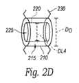
本明細書で使用される場合、「ジオメトリ」という用語は、要素のサイズ及び/または形状を含むことができる。したがって、本開示がジオメトリにおける変化を説明するとき、それは、要素のサイズにおける変化(例えば、小さな円から大きな円への移動)、要素の形状における変化(例えば、円から楕円への移動)、及び/または要素の形状及びサイズにおける変化(例えば、小さな円から大きな楕円への移動)を指すことができる。さまざまな実施形態では、「ジオメトリ」は、それぞれのシステムでの要素の相対的な配置及び/または位置を指す。As used herein, the term "geometry" can include the size and/or shape of an element. Thus, when this disclosure describes a change in geometry, it can refer to a change in the size of an element (e.g., moving from a small circle to a large circle), a change in the shape of an element (e.g., moving from a circle to an ellipse), and/or a change in the shape and size of an element (e.g., moving from a small circle to a large ellipse). In various embodiments, "geometry" refers to the relative placement and/or position of elements in a respective system.
本明細書で使用される場合、「製造ジオメトリ」という用語は、形状記憶構成要素の好ましいジオメトリ構成を指すことができる。例えば、形状記憶構成要素は、機械的応力またはその他の変形がない製造ジオメトリを概して呈する。製造ジオメトリは、「切断されたままの」ジオメトリ、温度設定されたジオメトリ、形状設定されたジオメトリなどを含むことができる。As used herein, the term "manufactured geometry" can refer to a preferred geometric configuration of a shape memory component. For example, a shape memory component generally assumes a manufactured geometry in the absence of mechanical stress or other deformation. A manufactured geometry can include an "as cut" geometry, a temperature set geometry, a shape set geometry, etc.
本明細書で提供される表題は、便宜のためだけのものであり、本願により特許請求される本技術の範囲または意味を解釈するものではない。The headings provided herein are for convenience only and do not interpret the scope or meaning of the technology claimed herein.
A.心不全の治療のための心房間シャント
心不全は、患者が経験する駆出率に基づいて、(1)病歴的に拡張期心不全と称されるHFpEF、または(2)病歴的に収縮期心不全と称されるHFrEF、という少なくとも2つのカテゴリのうちの1つにクラス分類されることができる。HFrEFの1つの定義は、左心室駆出率が35%~40%よりも低いことである。心不全のクラス分類ごとの根底にある病態生理及び治療計画は、関連があるにもかかわらず、かなり異なる場合がある。例えば、HFrEFの症状を治療し、時には疾患の進行を遅らせる、または元に戻すのに有用であることができる確立された薬物療法があるが、HFpEFに利用できる薬物療法は限られており、有効性は疑わしいだけである。 A. Interatrial Shunts for the Treatment of Heart Failure Heart failure can be classified into one of at least two categories based on the ejection fraction experienced by the patient: (1) HFpEF, historically referred to as diastolic heart failure, or (2) HFrEF, historically referred to as systolic heart failure. One definition of HFrEF is a left ventricular ejection fraction lower than 35%-40%. The underlying pathophysiology and treatment regimens for each class of heart failure, although related, can be quite different. For example, while there are established pharmacologic therapies that can be useful in treating the symptoms of HFrEF and sometimes slowing or reversing disease progression, pharmacologic therapies available for HFpEF are limited and of only questionable efficacy.
心不全患者では、左心室(LV)での機能異常は、LAでの圧力上昇につながる。これは、LAに与えられる、肺静脈系での圧力が高くなることに直接つながる。肺静脈圧が上昇すると、流体が毛細血管から押し出され、肺に押し込まれる。この流体の蓄積は、肺のうっ血、及び軽い身体活動でも息切れと労作の兆候を含む心不全の症状の多くを引き起こす。HFのリスク因子は、腎障害、高血圧症、高脂血症、糖尿病、喫煙、肥満症、老齢、及び閉塞性睡眠時無呼吸を含む。HF患者は、LVの硬化が進んでいる可能性があることが原因で、拡張期の左心室の弛緩が減少した結果、圧力が上昇し、心室の充満が不十分になる。また、HF患者は、心房細動及び肺高血圧症のリスクが高い可能性があり、通常、治療の選択肢を複雑にする可能性のある他の併存疾患を有する。In patients with heart failure, abnormal functioning in the left ventricle (LV) leads to increased pressure in the LA. This directly translates to higher pressure in the pulmonary venous system being applied to the LA. As pulmonary venous pressure increases, fluid is forced out of the capillaries and into the lungs. This fluid accumulation causes many of the symptoms of heart failure, including pulmonary congestion and signs of shortness of breath and exertion even with light physical activity. Risk factors for HF include renal impairment, hypertension, hyperlipidemia, diabetes, smoking, obesity, older age, and obstructive sleep apnea. HF patients may have increased stiffness in the LV, which can lead to reduced relaxation of the left ventricle during diastole, resulting in increased pressure and inadequate ventricular filling. HF patients may also be at increased risk for atrial fibrillation and pulmonary hypertension, and usually have other comorbidities that may complicate treatment options.
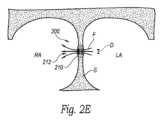
心房間シャントは、上昇した左心房圧を低下させる方法として最近提案されており、この新たなクラスの心血管の治療的介入は、有意な臨床見込みがあることが実証されている。例えば、図1は、LAとRAとの間の中隔壁内での従来のシャント配置を示す。ほとんどの従来の心房間シャント(例えば、シャント10)は、穴部を作製することによって、またはルーメンを備えたインプラントを心房中隔壁内に挿入することによって、LAとRAとの間に流体連通路を作製することを伴う。そのため、左心房圧の上昇は、LAをRAに除荷することで部分的に緩和されることがある。早期の臨床試験では、このアプローチは心不全の症状を改善することが示されている。Interatrial shunts have recently been proposed as a way to reduce elevated left atrial pressure, and this new class of cardiovascular therapeutic intervention has demonstrated significant clinical promise. For example, FIG. 1 shows a conventional shunt placement in the septal wall between the LA and RA. Most conventional interatrial shunts (e.g., shunt 10) involve creating a fluid communication path between the LA and RA by creating a hole or by inserting an implant with a lumen into the atrial septal wall. Thus, elevated left atrial pressure may be partially alleviated by unloading the LA to the RA. Early clinical trials have shown that this approach improves symptoms of heart failure.
多くの従来の心房間シャントに関する課題の1つは、シャントルーメンの最も適切なサイズ及び形状を決定することである。ルーメンが小さすぎると、LAが適切に除荷されず、症状が緩和されない場合がある。ルーメンが大きすぎると、RAと右心が概ね過負荷になり、患者に新たな問題が発生する可能性がある。さらに、一部にはHFpEF(及び程度は低いがHFrEF)の病態生理が完全に理解されていないため、圧力低下と臨床転帰との間の関連性、及び最適化された転帰に必要な圧力低下の程度は、まだ完全には理解されていない。そのため、臨床医は適切なサイズのシャントを選択する(限られた臨床エビデンスに基づいて)際に最善の推測をすることを余儀なくされ、通常、時間の経過とともにサイズを調整することはできない。さらに悪いことに、臨床医は、個々の患者の健康及び予測された反応ではなく、一般因子(例えば、患者の解剖学的構造のサイズ、一度に一枚のスナップショットで撮られた患者の血行動態測定値など)に基づいてシャントのサイズ及び/または利用可能なデバイスの設計を選択する必要がある。従来のデバイスでは、臨床医は、例えば疾患の進行などの患者の状態の変化に応じて、デバイスが植え込まれると、治療を調整する、または量を決定する能力を有していない。対照的に、本技術の実施形態に従って構成される心房間シャントシステムにより、臨床医は、患者に基づいて、周術期または植え込み後、サイズを選択することができる。One of the challenges with many conventional interatrial shunts is determining the most appropriate size and shape of the shunt lumen. If the lumen is too small, the LA may not be properly unloaded and symptoms may not be relieved. If the lumen is too large, the RA and right heart may be generally overloaded, creating new problems for the patient. Furthermore, due in part to an incomplete understanding of the pathophysiology of HFpEF (and to a lesser extent HFrEF), the association between pressure reduction and clinical outcome, and the degree of pressure reduction required for optimized outcomes, are not yet fully understood. As a result, clinicians are forced to make their best guess when selecting an appropriately sized shunt (based on limited clinical evidence) and typically cannot adjust the size over time. To make matters worse, clinicians must select the shunt size and/or available device design based on general factors (e.g., the size of the patient's anatomy, hemodynamic measurements of the patient taken in one snapshot at a time, etc.) rather than the health and predicted response of the individual patient. With conventional devices, clinicians do not have the ability to adjust or dose therapy once the device is implanted in response to changes in the patient's condition, such as disease progression. In contrast, an interatrial shunt system configured in accordance with embodiments of the present technology allows clinicians to select size perioperatively or post-implantation based on the patient.
B.形状記憶作動アセンブリ
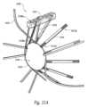
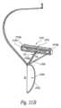
上記のように、本技術は、一般に心房間シャントシステムを対象とする。それらのようなシステムは、中隔壁で、またはそれに隣接して患者に植え込み可能なシャント要素を含む。いくつかの実施形態では、シャント要素は、中隔壁との界面で連結するように構成されるフレーム、及びフレームに結合されてルーメンを画定するメンブランを含む。シャント要素(例えば、ルーメン)は、患者のLA及びRAを流体連結し、それらの間の血流を促進することができる。いくつかの実施形態では、シャント要素は、作動アセンブリを含み、及び/またはそれに動作可能に結合され、この作動アセンブリは、LAとRAとの間の血流を選択的に制御するために侵襲的に、及び/または非侵襲的に調整可能である。いくつかの実施形態では、システムは、とりわけ、エネルギー受容構成要素、エネルギー貯蔵構成要素、及び/または1つ以上のセンサをさらに含むことができる。 B. Shape Memory Actuating Assembly As mentioned above, the present technology is generally directed to interatrial shunt systems. Such systems include a shunt element implantable in a patient at or adjacent to the septal wall. In some embodiments, the shunt element includes a frame configured to interface with the septal wall, and a membrane coupled to the frame defining a lumen. The shunt element (e.g., the lumen) can fluidly connect the LA and RA of the patient to facilitate blood flow therebetween. In some embodiments, the shunt element includes and/or is operably coupled to an actuating assembly that is invasively and/or non-invasively adjustable to selectively control blood flow between the LA and RA. In some embodiments, the system can further include, among others, an energy receiving component, an energy storing component, and/or one or more sensors.
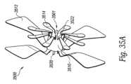
いくつかの実施形態では、心房間シャントシステムは、1つ以上の作動要素を有する作動アセンブリを含む。以下で詳細に説明されるように、作動要素は、シャント要素を介して延在するルーメンのジオメトリまたは他の特性を変化させ、ルーメンを通る流体の流量を変えるように構成される。例えば、いくつかの実施形態では、作動要素は、ルーメンを通る流体の流量を変えるようにルーメンのサイズ及び/または形状を選択的に変化させることができる。特に、作動要素は、入力に応じて、ルーメン(またはルーメンの一部分)の直径を選択的に拡大させる、及び/またはルーメン(またはルーメンの一部分)の直径を選択的に縮小させるように構成されることができる。本開示全体を通して、直径を調整すること(例えば、直径を拡大させること、直径を縮小させることなど)への言及は、ルーメンの水力直径または相当直径を調整すること、ルーメンの特定の位置での直径を調整すること、及び/またはルーメンの長さ(例えば、全長)に沿って直径を調整することを指すことができる。他の実施形態では、作動要素は、その他の方法でルーメンの形状またはジオメトリに影響するように構成される。いくつかの実施形態では、作動要素は、ルーメンのオリフィスまたはアパーチャ(例えば、それぞれがLAもしくはRA内に、またはそれに隣接して位置決めされる流入オリフィスまたは流出オリフィス)のジオメトリ(例えば、断面積、直径、寸法)を調整するように構成される。例えば、作動要素は、入力に応じて、RA内の流出オリフィスの断面積を選択的に拡大させる、及び/またはRA内の流出オリフィスの断面積を選択的に縮小させるように構成されることができる。いくつかの実施形態では、作動要素は、ルーメン及びルーメンオリフィスの両方のジオメトリを選択的に変化させることができる。In some embodiments, the interatrial shunt system includes an actuating assembly having one or more actuating elements. As described in detail below, the actuating elements are configured to change the geometry or other characteristics of the lumen extending through the shunt element to alter the flow rate of fluid through the lumen. For example, in some embodiments, the actuating elements can selectively change the size and/or shape of the lumen to alter the flow rate of fluid through the lumen. In particular, the actuating elements can be configured to selectively enlarge the diameter of the lumen (or a portion of the lumen) and/or selectively reduce the diameter of the lumen (or a portion of the lumen) in response to an input. Throughout this disclosure, references to adjusting a diameter (e.g., enlarging a diameter, reducing a diameter, etc.) can refer to adjusting the hydraulic or equivalent diameter of the lumen, adjusting a diameter at a particular location of the lumen, and/or adjusting a diameter along the length (e.g., the entire length) of the lumen. In other embodiments, the actuating elements are configured to affect the shape or geometry of the lumen in other ways. In some embodiments, the actuation element is configured to adjust the geometry (e.g., cross-sectional area, diameter, size) of a lumen orifice or aperture (e.g., an inflow or outflow orifice positioned in or adjacent to the LA or RA, respectively). For example, the actuation element can be configured to selectively enlarge the cross-sectional area of an outflow orifice in the RA and/or selectively reduce the cross-sectional area of an outflow orifice in the RA in response to an input. In some embodiments, the actuation element can selectively change the geometry of both the lumen and the lumen orifice.
したがって、作動要素は、ルーメン及び/またはオリフィスにおけるジオメトリの変化を駆動するために、シャント要素に結合されることができる、及び/またはシャント要素内に含まれることができる。いくつかの実施形態では、作動要素は、シャント要素の一部であり、ルーメンを少なくとも部分的に画定する。例えば、作動要素は、メンブラン内に配置されることができ、またはその他の方法でメンブランに結合されることができ、このメンブランは、シャント要素のルーメンを少なくとも部分的に画定する。他の実施形態では、作動要素は、シャント要素から離隔されるが、シャント要素に動作可能に結合される。Thus, the actuating element can be coupled to and/or included within the shunt element to drive a geometric change in the lumen and/or orifice. In some embodiments, the actuating element is part of the shunt element and at least partially defines the lumen. For example, the actuating element can be disposed within or otherwise coupled to a membrane that at least partially defines the lumen of the shunt element. In other embodiments, the actuating element is spaced from but operably coupled to the shunt element.
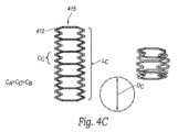
いくつかの実施形態では、作動要素の少なくとも一部分は、形状記憶要素を含むことができる。形状記憶部分は、ニチノールなどの形状記憶金属または合金、形状記憶ポリマー、pHに基づいた形状記憶材料、または入力に応じて移動する、もしくはその他の方法で調整するように構成される任意の他の適切な材料を含むことができる。例えば、作動要素は、1つ以上のニチノール要素を含むことができ、これら1つ以上のニチノール要素は、熱が加えられ、この熱がニチノール要素の温度を材料の変換温度よりも上昇させることに応じて、形状を変化させるように構成される。それらのような実施形態では、作動要素は、エネルギーが加えられてニチノール要素(複数可)を加熱することによって、選択的に作動することができる。いくつかの実施形態では、形状記憶材料は、ルーメンの少なくとも一部分の周りに延在することができる。いくつかの実施形態では、形状記憶材料は、ルーメンオリフィスの少なくとも一部分の周りに延在することができる。いくつかの実施形態では、形状記憶材料は、ルーメン及び/またはルーメンオリフィスから分離されるが、それらに動作可能に結合されることができる。In some embodiments, at least a portion of the actuating element can include a shape memory element. The shape memory portion can include a shape memory metal or alloy, such as Nitinol, a shape memory polymer, a pH-based shape memory material, or any other suitable material configured to move or otherwise adjust in response to an input. For example, the actuating element can include one or more Nitinol elements configured to change shape in response to the application of heat that raises the temperature of the Nitinol element above a transformation temperature of the material. In such embodiments, the actuating element can be selectively actuated by the application of energy to heat the Nitinol element(s). In some embodiments, the shape memory material can extend around at least a portion of the lumen. In some embodiments, the shape memory material can extend around at least a portion of the lumen orifice. In some embodiments, the shape memory material can be separate from but operably coupled to the lumen and/or lumen orifice.
作動要素の移動は、外部から加えられた入力によって、及び/または形状記憶効果(例えば、温度の変化によって駆動される)の使用によって生じることができる。形状記憶効果により、要素をその元の、または好ましく形状設定されたジオメトリ構成(本明細書では「製造ジオメトリ」または「温度設定されたジオメトリ」とも称される)から変更した変形の大部分または全体が、作動要素の動作中に元に戻されることができる。例えば、十分な加熱により、アクチュエータ材料内の材料状態における変化(例えば、相変化)を生じ、一時的に上昇した内部応力を誘起し、この内部応力が元の形状設定されたジオメトリ構成に向けて形状変化を促進することによって、変形が元に戻されることができる。形状記憶合金の場合、状態における変化は、低温でのマルテンサイト相(その代替に、R相)から高温でのオーステナイト相(その代替に、R相)への変化であることができる。形状記憶ポリマーの場合、状態における変化は、ガラス転移点または溶融温度による変化であることができる。材料状態における変化により、アクチュエータ要素に外部からいかなる応力も加えることなく、材料の変形(複数可)(例えば、その製造ジオメトリに対する変形)が回復することができる。すなわち、第一温度(例えば、体温)で材料に存在する変形は、材料を第二(例えば、より高い)温度まで上昇させることによって、回復する、及び/または変わることができる。冷却すると(そして、例えば、マルテンサイト相に戻すなど、状態を再変化させると)、アクチュエータ要素は、その製造ジオメトリをほぼ保定することができる。ただし、材料がこの比較的低温の状態にあるので、材料を熱弾性変形させるために必要な力または応力が低くなることができ、その後にいかなる外部応力が加えられても、アクチュエータ要素が製造ジオメトリから離れて再び変形することができる。Movement of the actuating element can be caused by an externally applied input and/or by the use of a shape memory effect (e.g., driven by a change in temperature). The shape memory effect allows a large or total deformation that has altered the element from its original or preferred shaped geometry configuration (also referred to herein as the "manufactured geometry" or "temperature-set geometry") to be reversed during operation of the actuating element. For example, sufficient heating can cause a change in material state (e.g., a phase change) in the actuator material, inducing a temporarily elevated internal stress that drives the shape change toward the original shaped geometry configuration, thereby reversing the deformation. In the case of a shape memory alloy, the change in state can be from a martensite phase (alternatively, R-phase) at low temperature to an austenite phase (alternatively, R-phase) at high temperature. In the case of a shape memory polymer, the change in state can be due to a glass transition or melting temperature. The change in material state allows the material to recover its deformation(s) (e.g., relative to its manufactured geometry) without any external stress being applied to the actuator element. That is, the deformation present in the material at a first temperature (e.g., body temperature) can be restored and/or altered by raising the material to a second (e.g., higher) temperature. Upon cooling (and re-changing state, e.g., back to the martensitic phase), the actuator element can retain approximately its manufactured geometry; however, because the material is in this relatively cool state, the force or stress required to thermoelastically deform the material can be lower, and any subsequent application of external stress can cause the actuator element to re-deform away from the manufactured geometry.
形状記憶合金作動要素は、状態における変化が起こる転移温度(例えば、オーステナイト開始温度、オーステナイト最終温度など)が閾値温度(例えば、体温)より高いように処理されることができる。例えば、転移温度は約40℃、約45℃、約50℃、約55℃、約60℃、または別のより高いまたはより低い温度に設定されることができる。いくつかの実施形態では、アクチュエータ材料は、体温からオーステナイト開始温度より高い温度(または代替に、R相開始温度より高い温度)に加熱された結果、第一状態(例えば、体温での熱弾性マルテンサイト相または熱弾性R相)での材料の上部プラトー応力(例えば、「UPS_体温」)は、加熱状態(例えば、超弾性状態)での材料の上部プラトー応力(例えば、「UPS_作動温度」)より低くなることにより、部分的または完全な自由回復が達成される。例えば、アクチュエータ材料は、UPS_作動温度>UPS_体温、のように加熱されることができる。いくつかの実施形態では、アクチュエータ材料は、体温からオーステナイト開始温度より高い温度(または代替に、R相開始温度より高い温度)に加熱された結果、第一状態(例えば、体温での熱弾性マルテンサイトまたは熱弾性R相)での材料の上部プラトー応力は、加熱状態(例えば、超弾性状態)での材料の下部プラトー応力(例えば、「LPS」)より低くなることにより、部分的または完全な自由回復が達成される。例えば、アクチュエータ材料は、LPS_活性化温度>UPS_体温、のように構築されることができる。いくつかの実施形態では、アクチュエータ材料は、体温からオーステナイト開始温度より高い温度(または代替に、R相開始温度より高い温度)に加熱された結果、第一状態(例えば、熱弾性マルテンサイトまたは熱弾性R相)での材料の上部プラトー応力は、加熱状態での材料の下部プラトー応力より高くなることにより、部分的な自由回復が達成される。例えば、アクチュエータ材料は、LPS_活性化温度<UPS_体温、のように構築されることができる。The shape memory alloy actuating element can be processed such that the transition temperature at which the change in state occurs (e.g., austenite start temperature, austenite finish temperature, etc.) is greater than a threshold temperature (e.g., body temperature). For example, the transition temperature can be set to about 40°C, about 45°C, about 50°C, about 55°C, about 60°C, or another higher or lower temperature. In some embodiments, the actuator material is heated from body temperature to a temperature greater than the austenite start temperature (or alternatively, a temperature greater than the R-phase start temperature) such that the upper plateau stress (e.g., "UPS_body temperature") of the material in the first state (e.g., thermoelastic martensite phase or thermoelastic R-phase at body temperature) is less than the upper plateau stress (e.g., "UPS_actuation temperature") of the material in the heated state (e.g., superelastic state), thereby achieving partial or complete free recovery. For example, the actuator material can be heated such that UPS_actuation temperature>UPS_body temperature. In some embodiments, the actuator material is heated from body temperature to a temperature above the austenite start temperature (or alternatively, above the R-phase start temperature) such that the upper plateau stress of the material in the first state (e.g., thermoelastic martensite or thermoelastic R-phase at body temperature) is lower than the lower plateau stress (e.g., "LPS") of the material in the heated state (e.g., superelastic state), thereby achieving partial or complete free recovery. For example, the actuator material can be constructed such that LPS_activation temperature>UPS_body temperature. In some embodiments, the actuator material is heated from body temperature to a temperature above the austenite start temperature (or alternatively, above the R-phase start temperature) such that the upper plateau stress of the material in the first state (e.g., thermoelastic martensite or thermoelastic R-phase) is higher than the lower plateau stress of the material in the heated state, thereby achieving partial free recovery. For example, the actuator material can be constructed such that LPS_activation temperature<UPS_body temperature.
いくつかの実施形態では、作動アセンブリは、少なくとも2つの作動要素(例えば、異なる製造ジオメトリを有する)を結合して、複合作動要素(「作動アセンブリ」とも称されることができる)を形成することによって形成される。いくつかの実施形態では、複合作動要素を含む要素のうちの少なくとも1つは、形状記憶要素である。いくつかの実施形態では、複合作動要素を含む両方の要素は、形状記憶要素である。いくつかの実施形態では、結合は、植え込み温度で熱弾性によって変形可能な(例えば、熱弾性マルテンサイトまたは熱弾性R相)状態にある少なくとも1つの作動要素を用いて実行される。いくつかの実施形態では、結合は、超弾性状態での少なくとも1つの作動要素(複数可)を用いて実行される。いくつかの実施形態では、流量制御要素は膨張性要素または収縮性要素を含み、この要素の変形は、より低い温度(例えば、体温)で力(例えば、バルーン膨張)を加えることによって、及び/またはより高い温度(例えば、オーステナイト開始またはR相開始の温度以上の温度)で熱(例えば、電気抵抗加熱)を加えることによって達成されることができる。いくつかの実施形態では、形状記憶構成要素は、ジオメトリ(例えば、断面積、直径、長さ、曲率半径、または周径)を含む様式で構築される。いくつかの実施形態では、少なくとも2つの作動要素は、ジオメトリ構成(例えば、直径)DA0及びDB0を有する(DA0>DB0)。いくつかの実施形態では、作動アセンブリは、実質的に同じジオメトリ構成(例えば、DA0=DB0)で構築された少なくとも2つの作動要素から形成される。流量制御要素は、患者への導入(すなわち、植え込み)前に、または患者への導入時に、2つ以上の結合された作動要素のうちの少なくとも1つがそれらの元のジオメトリ構成に対して変形されるように(例えば、DA1≠DA0、及び/またはDB1≠DB0のように)組み立てられることができる。いくつかの実施形態では、第一作動要素のジオメトリ(例えば、直径)がその元の構成に対して小さくなる(例えば、圧縮する)(例えば、DA1<DA0)ように、そして第二作動要素のジオメトリ(例えば、直径)がその元の構成に対して大きくなる(例えば、膨張する)(例えば、DB1>DB0)ように、少なくとも2つの結合された作動要素は、植え込み前に、または植え込み時に変形することができる。形状記憶構成要素が第一(例えば、マルテンサイト)材料状態にあると、所望の構成への作動要素の熱弾性変形は起こることができる。所与の温度で(例えば、平衡状態で)、結合されて変形した作動要素は、第一及び第二作動要素の形状設定された構成のいずれとも異なる寸法を有する複合ジオメトリ(例えば、断面積)を形成することができる。例えば、流量制御要素の複合ジオメトリ(例えば、直径、DC0)は、第一及び第二作動要素の形状設定された構成の間にあることができる(例えば、DA0>DC0>DB0)。 In some embodiments, the actuating assembly is formed by combining at least two actuating elements (e.g., having different manufacturing geometries) to form a composite actuating element (which may also be referred to as an "actuating assembly"). In some embodiments, at least one of the elements that comprise the composite actuating element is a shape memory element. In some embodiments, both elements that comprise the composite actuating element are shape memory elements. In some embodiments, the combining is performed with at least one actuating element in a thermoelastically deformable (e.g., thermoelastic martensite or thermoelastic R-phase) state at implantation temperature. In some embodiments, the combining is performed with at least one actuating element(s) in a superelastic state. In some embodiments, the flow control element comprises an expanding or contracting element, the deformation of which can be achieved by applying a force (e.g., balloon expansion) at a lower temperature (e.g., body temperature) and/or by applying heat (e.g., electrical resistance heating) at a higher temperature (e.g., a temperature above the austenite start or R-phase start temperature). In some embodiments, the shape memory component is constructed in a manner that includes a geometry (e.g., cross-sectional area, diameter, length, radius of curvature, or circumference). In some embodiments, at least two actuating elements have geometric configurations (e.g., diameters) DA0 and DB0 , where DA0 >DB0 . In some embodiments, an actuating assembly is formed from at least two actuating elements constructed with substantially the same geometric configuration (e.g., DA0 =DB0 ). The flow control element can be assembled such that prior to introduction (i.e., implantation) into a patient or upon introduction into a patient, at least one of the two or more coupled actuating elements is transformed relative to their original geometric configuration (e.g., such that DA1 ≠ DA0 and/or DB1 ≠ DB0 ). In some embodiments, at least two coupled actuating elements can be deformed prior to or during implantation such that the geometry (e.g., diameter) of the first actuating element is reduced (e.g., compressed) relative to its original configuration (e.g., DA1 <DA0 ) and the geometry (e.g., diameter) of the second actuating element is increased (e.g., expanded) relative to its original configuration (e.g., DB1 >DB0 ). Thermoelastic deformation of the actuating elements to a desired configuration can occur when the shape memory components are in a first (e.g., martensitic) material state. At a given temperature (e.g., at equilibrium), the coupled deformed actuating elements can form a composite geometry (e.g., cross-sectional area) having dimensions different from either of the shaped configurations of the first and second actuating elements. For example, the composite geometry (e.g., diameter, DC0 ) of the flow control element can be between the shaped configurations of the first and second actuating elements (e.g., DA0 >DC0 >DB0 ).
作動アセンブリは、動作中(例えば、作動要素の作動中)、その複合ジオメトリ及び/または寸法が変わるように(例えば、DC1≠DC0のように)形成されることができる。流量制御要素は、流路(例えば、ルーメン)の全体の寸法における変化を引き起こすことができる。例えば、全体の寸法は、全体の断面積、直径、長さ、周径、または別の属性を含むことができる。一実施形態では、第一及び第二作動要素は、結合されて複合要素を形成するように配置された結果、第一作動要素が移動する(例えば、熱弾性マルテンサイト転移によって自由回復を達成する)ことは、第二作動要素が相補的に完全に、または部分的に移動することを、例えば、比較的可鍛性の第二作動要素が熱弾性マルテンサイト(または熱弾性R相)材料状態に少なくとも部分的にある間にその第二作動要素の熱弾性回復性変形を誘起することなどを、伴う(例えば、引き起こす)。(本明細書では簡潔にするために、さまざまな実施形態では、「比較的可鍛性」という用語は、構成要素が、別の構成要素と比較されたとき、または異なる材料状態での同じ構成要素と比較されたとき、それを変形させるために必要な力または応力が低い材料状態を説明するために使用される)。移動(複数可)は、複合要素の圧縮(例えば、収縮)または膨張(例えば、開放)を含むことができる。移動は、完全回復性または部分回復性であることができる、たわみまたは変形を有することができる。第二作動要素の相補的な移動は、(a)同軸に沿った移動、(b)同軸を中心にした移動、もしくは(c)第一作動要素の一次移動と同じ寸法(例えば、半径方向)に沿った移動、または別の移動を含むことができる。いくつかの実施形態では、圧縮したジオメトリから、より大きく形状設定された構成のジオメトリに向けた第一作動要素の作動は、第一作動要素と第二作動要素との結合によって複合ジオメトリを膨張させる。いくつかの実施形態では、この膨張により、複合ジオメトリは、その平衡状態よりも大きいが、第一作動要素の元の構成のサイズよりも小さいサイズに置かれる(例えば、DA0>DC1>DC0)。いくつかの実施形態では、膨張したジオメトリからより小さな元の構成のジオメトリに向けた第二作動要素の作動は、第二作動要素と第一作動要素との結合によって複合ジオメトリを収縮させる(例えば、圧縮させる)。いくつかの実施形態では、この圧縮により、複合ジオメトリは、その平衡状態よりも小さいが、第二作動要素の元の構成のサイズよりも大きいサイズに置かれる(例えば、DC0>DC1>DB0)。 The actuating assembly can be configured to change its composite geometry and/or dimensions (e.g., DC1 ≠ DC0 ) during operation (e.g., during actuation of the actuating elements). The flow control element can cause a change in the overall dimensions of the flow passage (e.g., lumen). For example, the overall dimensions can include an overall cross-sectional area, diameter, length, circumference, or another attribute. In one embodiment, the first and second actuating elements are arranged to be combined to form a composite element such that a movement of the first actuating element (e.g., achieving free recovery via a thermoelastic martensitic transformation) is accompanied (e.g., causes) by a complementary full or partial movement of the second actuating element, such as inducing a thermoelastically recoverable deformation of the relatively malleable second actuating element while the second actuating element is at least partially in a thermoelastic martensite (or thermoelastic R-phase) material state. (For brevity herein, in various embodiments, the term "relatively malleable" is used to describe a material state in which a component requires a lower force or stress to deform it when compared to another component or compared to the same component in a different material state). The movement(s) can include a compression (e.g., contraction) or expansion (e.g., opening) of the composite element. The movement can have a deflection or deformation that can be fully or partially recoverable. The complementary movement of the second actuating element can include (a) a movement along the same axis, (b) a movement about the same axis, or (c) a movement along the same dimension (e.g., radial) as the primary movement of the first actuating element, or another movement. In some embodiments, actuation of the first actuating element from a compressed geometry toward a geometry of a larger shaped configuration expands the composite geometry by coupling the first and second actuating elements. In some embodiments, this expansion places the composite geometry at a size larger than its equilibrium state but smaller than the size of the original configuration of the first actuating element (e.g., DA0 >DC1 >DC0 ). In some embodiments, actuation of the second actuating element from an expanded geometry toward a geometry of a smaller original configuration contracts (e.g., compresses) the composite geometry by coupling the second actuating element with the first actuating element. In some embodiments, this compression places the composite geometry at a size smaller than its equilibrium state but larger than the size of the second actuating element's original configuration (eg, DC0 >DC1 >DB0 ).
本技術の一実施形態の動作方法では、流量制御要素の第一作動要素の選択的加熱により、第一作動要素は、その元のジオメトリ構成に向けて(例えば、DA1からDA0に向けて)作動する。作動は、第一作動要素の温度を少なくとも閾値転移温度まで上昇させることによって引き起こされることができる。転移温度は、相転移温度(例えば、R相開始温度、オーステナイト開始温度、R相終了温度、またはオーステナイト終了温度)であることができる。転移温度以上に温度が上昇すると、材料が第一相(例えば、マルテンサイトまたはR相)から第二相(例えば、R相またはオーステナイト)に変化することが誘起されることができる。第一作動要素の作動中、第二作動要素は、概して加熱されないため(例えば、体温またはその近くのままであるため)、第一(例えば、マルテンサイトまたはR相)材料状態のままである。そのため、第二作動要素は、この材料状態で比較的可鍛性であることができることにより、第一作動要素の部分自由回復または完全自由回復がもとで上昇した力は、結合された第二要素の形状及び/またはジオメトリにおける変化(例えば、圧縮運動または収縮運動)を駆動することができる。この材料状態での第二作動要素の比較的可鍛性の性質が原因で、第二作動要素は、実質的な回復なしで(例えば、概して線形弾性回復のみで)、この誘起された形状及び/またはジオメトリの変化を大部分保定することができる。 In a method of operation of one embodiment of the present technology, selective heating of a first actuating element of a flow control element actuates the first actuating element toward its original geometric configuration (e.g., from DA1 toward DA0 ). Actuation can be triggered by increasing the temperature of the first actuating element to at least a threshold transition temperature. The transition temperature can be a phase transition temperature (e.g., an R-phase start temperature, an austenite start temperature, an R-phase finish temperature, or an austenite finish temperature). An increase in temperature above the transition temperature can induce a material to change from a first phase (e.g., martensite or R-phase) to a second phase (e.g., R-phase or austenite). During actuation of the first actuating element, the second actuating element remains in a first (e.g., martensite or R-phase) material state because it is generally not heated (e.g., remains at or near body temperature). Thus, the second actuating element can be relatively malleable in this material state such that the force generated by the partial or full free recovery of the first actuating element can drive a change in the shape and/or geometry of the associated second element (e.g., a compressive or contractive movement). Due to the relatively malleable nature of the second actuating element in this material state, the second actuating element can largely retain this induced shape and/or geometry change without substantial recovery (e.g., with only generally linear elastic recovery).
第一作動要素の加熱期間の完了に続いて、第一作動要素は、冷却され、比較的可鍛性である低温相(例えば、マルテンサイトまたはR相)に転移する。複合流量制御要素の構成(例えば、そのジオメトリ)における誘起された変化を元に戻すために、第二作動要素は、その転移温度以上に加熱されることにより、相変化(例えば、R相またはオーステナイト)が誘起された結果、ジオメトリでは、その元のジオメトリの構成に向けて(例えば、DB1からDB0に向けて)部分または完全自由回復することができる。この間、第一作動要素が選択的に加熱されず、比較的可鍛性ではないため、第二作動要素がその元のジオメトリ構成に戻ると、流量制御要素の複合ジオメトリが変化する(例えば、サイズが縮小する)。いくつかの実施形態では、流量制御要素のジオメトリは、前述の動作を繰り返すことによって、繰り返し(例えば、膨張と収縮との間で)トグルされることができる。作動要素の加熱は、入射エネルギーを与えることによって(例えば、レーザー、抵抗加熱、または誘導結合によって)達成されることができる。入射エネルギーの供給源は、患者の内部(例えば、カテーテルによって送達される)か、外部(例えば、非侵襲的に送達されるRFエネルギー)かいずれかであることができる。 Following completion of the heating period of the first actuating element, the first actuating element is cooled and transitions to a relatively malleable low-temperature phase (e.g., martensite or R-phase). To reverse the induced change in the configuration (e.g., its geometry) of the composite flow control element, the second actuating element is heated above its transition temperature to induce a phase change (e.g., R-phase or austenite) such that the geometry can partially or fully recover toward its original geometric configuration (e.g., from DB1 toward DB0 ). During this time, the composite geometry of the flow control element changes (e.g., shrinks in size) as the second actuating element returns to its original geometric configuration because the first actuating element is selectively unheated and relatively unmalleable. In some embodiments, the geometry of the flow control element can be toggled repeatedly (e.g., between expansion and contraction) by repeating the aforementioned operations. Heating of the actuating element can be achieved by providing incident energy (e.g., by laser, resistive heating, or inductive coupling). The source of incident energy can be either internal to the patient (eg, delivered by a catheter) or external (eg, RF energy delivered non-invasively).
いくつかの実施形態では、第一作動要素は、第二作動要素から熱絶縁される、及び/または電気絶縁されることができる。さらに、いくつかの実施形態では、第一及び第二作動要素は、植え込み部位に隣接する組織及び血液から熱絶縁される、及び/または電気絶縁されることができる。In some embodiments, the first actuating element can be thermally and/or electrically isolated from the second actuating element. Additionally, in some embodiments, the first and second actuating elements can be thermally and/or electrically isolated from tissue and blood adjacent to the implantation site.
したがって、本技術は、2つ以上の形状記憶材料作動要素を含む作動アセンブリを提供し、これら2つ以上の形状記憶材料作動要素は、異なるジオメトリ構成に製造され、合わせて結合される。追加の実施形態では、2つ以上の作動要素が拮抗的または相補的な方法で機能し、作動アセンブリのジオメトリ特徴を操作するので、ジオメトリ構成は類似していてもよい。いくつかの実施形態では、作動要素は同様の化学組成及び/または熱機械的後処理で製造されることができる、すなわち、それらは同様の相転移温度プロファイルを有することができる。さらなる実施形態では、作動アセンブリは2つ以上の作動要素を含むことができ、これら2つ以上の作動要素は、異なる化学組成及び/または熱機械的後処理で製造されているため、それらは、同一の相転移温度プロファイルを共有しない。そのような実施形態の動作では、エネルギーは、複合作動アセンブリ全体(例えば、2つ以上の個別の作動要素から構成される)に与えられてもよく、すべての個別の作動要素は、それらの元のジオメトリ構成に向けて同様に変形しなくてもよい。例えば、第一作動要素は第一転移温度プロファイルを有してもよく、第二作動要素はより高い第二転移温度プロファイルを有してもよい。複合作動アセンブリを第一転移温度より高いが第二転移温度より低い温度(例えば、R相開始、オーステナイト開始、R相終了、またはオーステナイト終了の温度)まで加熱すると、第二作動要素よりも第一作動要素でより実質的な熱弾性回復が誘起される。これにより、作動アセンブリの第一ジオメトリの変化が生じる。複合作動アセンブリを第一及び第二転移温度の両方より高い温度(例えば、R相開始、オーステナイト開始、R相終了、またはオーステナイト終了の温度)まで加熱すると、両方の作動要素では、意味のある熱弾性回復及び作動が誘起されることができる。これにより、作動アセンブリの第二ジオメトリの変化が生じるが、この第二ジオメトリの変化は第一ジオメトリの変化とは異なってもよい。Thus, the present technology provides an actuation assembly including two or more shape memory material actuation elements, which are fabricated in different geometric configurations and bonded together. In additional embodiments, the geometric configurations may be similar because the two or more actuation elements function in an antagonistic or complementary manner to manipulate the geometric features of the actuation assembly. In some embodiments, the actuation elements may be fabricated with similar chemical compositions and/or thermomechanical post-treatments, i.e., they may have similar phase transition temperature profiles. In further embodiments, the actuation assembly may include two or more actuation elements, which are fabricated with different chemical compositions and/or thermomechanical post-treatments, so that they do not share the same phase transition temperature profile. In operation of such an embodiment, energy may be applied to the entire composite actuation assembly (e.g., comprised of two or more individual actuation elements), and all the individual actuation elements may not deform similarly toward their original geometric configurations. For example, a first actuation element may have a first transition temperature profile, and a second actuation element may have a higher second transition temperature profile. Heating the composite actuating assembly to a temperature above the first transition temperature but below the second transition temperature (e.g., an R-phase start, austenite start, R-phase finish, or austenite finish temperature) induces more substantial thermoelastic recovery in the first actuating element than in the second actuating element, which results in a change in the first geometry of the actuating assembly. Heating the composite actuating assembly to a temperature above both the first and second transition temperatures (e.g., an R-phase start, austenite start, R-phase finish, or austenite finish temperature) can induce significant thermoelastic recovery and actuation in both actuating elements, which results in a change in the second geometry of the actuating assembly, which may be different from the change in the first geometry.
実施形態では、作動アセンブリのジオメトリの変化は、1つ以上の作動要素の作動に応じて、いくつかの状態の間でトグルされることができる。実施形態では、ジオメトリの変化の逆転(例えば、ルーメンが以前に小さくされた後に大きくされること)は、拮抗的な様式で機能するように結合される複数の形状記憶作動要素を利用することによって達成される。実施形態では、他の機構(例えば、ばね、ラチェット、シリコーンなどの弾性材料など)を作動要素と組み合わせて追加で、または代替に利用して、それらの作動要素に相補的な力または反力を与えることによって、作動アセンブリのジオメトリの変化に影響し得る。In embodiments, the change in geometry of the actuation assembly can be toggled between several states in response to actuation of one or more actuation elements. In embodiments, reversal of the change in geometry (e.g., making the lumen larger after it had previously been made smaller) is accomplished by utilizing multiple shape-memory actuation elements coupled to function in an antagonistic manner. In embodiments, other mechanisms (e.g., springs, ratchets, elastic materials such as silicone, etc.) may additionally or alternatively be utilized in combination with the actuation elements to affect the change in geometry of the actuation assembly by providing complementary or counterforces to those actuation elements.
実施形態では、作動アセンブリは、複合構造体内の最大の作動要素よりも大きい断面のジオメトリまで、熱弾性によって膨張することができる。例えば、1つの作動要素は初期直径DA0を有してもよく、別の作動要素は初期直径DB0を有してもよい(例えば、DA0>DB0)。そのような複合システムでは、いずれかの作動要素の作動により、複合作動アセンブリはDB0~DA0(両端を含む)の範囲内の直径まで駆動される。例えば、医師が作動アセンブリをDA0より大きい直径まで膨張させる(例えば、バルーンを使用して)ことで、ツールの交差ができる場合(例えば、僧帽弁の経カテーテル展開中に)、作動アセンブリのルーメンは、後に、いずれかの作動要素を作動させて(例えば、熱を加えることによって)作動アセンブリの直径の回復を元の範囲DB0~DA0まで駆動することによって、熱弾性で回復されることができる。さまざまな実施形態では、作動アセンブリがDA0より大きい直径まで膨張すると、カテーテル、例えば、診断用カテーテルまたは治療用カテーテルなどの交差ができる。実施形態では、いずれか(または両方)の作動要素の塑性変形は、DA0より大きいルーメンへの膨張に起因することができる。その結果、達成可能な作動可能なルーメン範囲は、DB1~DA1にシフトすることができる(ここでは、永久塑性変形を考慮して、DB1>DB0及びDA1>DA0)。 In embodiments, the actuating assembly can be thermoelastically expanded to a cross-sectional geometry larger than the largest actuating element in the composite structure. For example, one actuating element can have an initial diameter DA0 and another actuating element can have an initial diameter DB0 (e.g., DA0 >DB0 ). In such a composite system, actuation of either actuating element drives the composite actuating assembly to a diameter within the range of DB0 to DA0 (inclusive). For example, if a physician expands the actuating assembly (e.g., using a balloon) to a diameter larger than DA0 to allow crossing of a tool (e.g., during transcatheter deployment of a mitral valve), the lumen of the actuating assembly can be thermoelastically restored by later actuating either actuating element (e.g., by applying heat) to drive the return of the diameter of the actuating assembly to the original range DB0 to DA0 . In various embodiments, expansion of the actuating assembly to a diameter larger than DA0 allows crossing of a catheter, such as a diagnostic or therapeutic catheter. In embodiments, plastic deformation of either (or both) actuation elements can result from expansion into a lumen larger than DA0 , and as a result, the achievable operable lumen range can shift from DB1 to DA1 (where DB1 >DB0 and DA1 >DA0 , taking into account permanent plastic deformation).
C.調整可能なフロールーメンを備えたシャントアセンブリ
本技術は、調整可能なフロールーメンを備えた心房間シャントアセンブリを提供する。例えば、図2A~2Fは、本技術の選択された実施形態に従って構成される、調整可能な心房間シャントシステム200(「システム200」)を示す。当業者が理解するように、図2A~2Fは、本明細書に記載のシャントシステムの調整可能な性質を実証するためにのみ提供される。本技術のさまざまな構成要素の追加の詳細は、図3A~35Bの具体的な実施形態を参照してより詳細に説明される。 C. Shunt Assembly with Adjustable Flow Lumen The present technology provides an inter-atrial shunt assembly with an adjustable flow lumen. For example, Figures 2A-2F show an adjustable inter-atrial shunt system 200 ("
最初に図2Aを参照すると、システム200は、フレーム210と、フレーム210から延出するアンカー230とを含む。システム200は、メンブラン220から構成されるシャント要素215をさらに含み、このメンブランは、そこを通り延在するルーメン225を画定する。以下に論じられるように、シャントシステム200が患者の心臓内の中隔壁Sを横切って植え込まれると、ルーメン225は、LA及びRAを流体連結し、それらの間で血液を短絡するように構成される。図2Aでは、ルーメン225は、第一直径DL1を有する第一構成で示される。図示されるように、ルーメン225は、第一構成では、その全長、または実質的にその全長に沿って概して一定の直径を有することができる。 Referring initially to FIG. 2A, the
ルーメン225のジオメトリは、そこを通る血液の流量を変化させるように調整されることができる。いくつかの実施形態では、ルーメン225の特定の位置での直径が調整される。例えば、図2Bを参照すると、ルーメン225の直径は、図2Aに示される第一構成と比較して、ルーメン225の中央部分で縮小し、砂時計形状の構成を呈する。砂時計の最も狭い部分でのルーメンの直径はDL2であり、これは、第一直径DL1よりも概して小さい。 The geometry of
他の実施形態では、ルーメン225の直径は、その全長に沿って調整される。例えば、図2Cを参照すると、ルーメン225の直径は、図2Aに示される第一構成と比較して、その軸方向の全長に沿って縮小することにより、略円筒形状を維持するが、第一構成よりも直径が小さい第二構成を有する。ルーメン225の直径は、その長さに沿って概して一定で、DL3であり、これは、第一直径DL1よりも概して小さく、直径DL2と同じである、または異なることができる。ルーメン225のジオメトリは、他の様式でも同様に調整されることができる。例えば、他の実施形態では、ルーメン225の直径は概して同じままであるが、1つ以上のルーメンオリフィスの直径は縮小している。 In other embodiments, the diameter of the
いくつかの実施形態では、ルーメン225のジオメトリは、そこを通る血液の流量を増加させるように調整されることができる。例えば、ルーメン225の直径は拡大することができる。図2Dに示されるように、ルーメン225の直径は、第一直径DL1よりも大きい直径DL4に拡大した。図2Dでは、ルーメン225がその軸方向の全長に沿って概して一定の直径を有することが示されているが、代替に、ルーメン225は、逆の砂時計形状を有してもよい(例えば、中央部分でのルーメン225の直径がルーメンオリフィスの直径よりも大きい)。 In some embodiments, the geometry of
図2Eに示されるように、システム200が第一構成(例えば、図2Aに示される構成)で中隔壁Sを横切って植え込まれると、ルーメン225は、第一量(例えば、流量、体積など)の血液がLAとRAとの間で流れることを可能にする。図2Fは、第二構成(すなわち、図2Cに示される構成)で中隔壁Sを横切って植え込まれるシステム200を示す。第一構成(すなわち、図2Aに示される構成)と比較して、第二構成は、LAとRAとの間の血流の減少をもたらす。当業者が理解することができるように、いくつかの実施形態では、システム200は、血流を減少させるために砂時計構成(すなわち、図2Bに示される構成)を呈することができる。同様に、システム200は、LAとRAとの間の血液の流量を増加させるために、図2Dに示される構成を呈することができる。As shown in FIG. 2E, when the
したがって、本技術は、調整可能な心房間シャントシステムを提供し、これらの調整可能な心房間シャントシステムは、フロールーメン及び/またはルーメンオリフィスのジオメトリを調整し、そこを通る血液の流量を変化させることができる。特に、図3A~23Cはルーメンジオメトリの調整を示し、図24~32はオリフィスジオメトリの調整を示す。システムは、以下でより詳細に説明される、さまざまな作動機構を使用して調整されることができる。The present technology thus provides adjustable interatrial shunt systems that allow for adjustment of the geometry of the flow lumen and/or lumen orifice to vary the flow rate of blood therethrough. In particular, Figures 3A-23C illustrate adjustment of the lumen geometry, and Figures 24-32 illustrate adjustment of the orifice geometry. The systems can be adjusted using a variety of actuation mechanisms, which are described in more detail below.
i.ステント様作動アセンブリ
図3Aは、本技術の一実施形態に従って構成される、心房間シャントデバイスの一部を形成する、結合された作動要素(第一作動要素305及び第二作動要素310)の概略図である。第一作動要素305は、第二作動要素310のもの(D2)とは異なる元のジオメトリ構成(例えば、D1)を有することができる。上記で提供されるように、D1は、第一作動要素305の水力直径または相当直径、特定の位置(例えば、ルーメンのオリフィス、ルーメンの中心点など)での第一作動要素305の直径、第一作動要素305のその長さの一部に沿った直径、及び/または別の寸法を指すことができる。同様に、D2は、第二作動要素310の水力直径または相当直径、特定の位置での第二作動要素310の直径、第二作動要素310のその長さの一部に沿った直径、及び/または別の寸法を指すことができる。第一及び第二作動要素305、310は、合わせて結合され、作動アセンブリ300を形成することができる。少なくとも2つの作動要素の直接結合は、縫合糸、接着剤/グルー、クリンプ/リベット、締まりばめ、溶接/はんだ、または当業者に知られている他の技術によって達成されることができる。少なくとも2つの作動要素の間接結合は、共通の中間要素への作動要素ごとの直接結合によって達成されることができる。組み立てに続いて、作動アセンブリ300は、第一温度(例えば、室温、体温など)では、個別の作動要素の元のジオメトリ構成の間で平衡状態にあるジオメトリ(例えば、D1>DC>D2)を有することができる。第一作動要素305の作動により、流量制御要素は、第一作動要素の元のジオメトリ構成に近いジオメトリ(DL)を呈する。例えば、第一作動要素の作動により、流量制御要素のジオメトリは拡大する(例えば、DL>DC)。第二作動要素310の作動により、流量制御要素は、第二作動要素の元のジオメトリ構成(D2)に近づく第二ジオメトリ(DS)を呈する。例えば、第二作動要素の作動により、流量制御要素のジオメトリは縮小する(例えば、DS<DC)。 i. Stent-Like Actuating Assembly FIG. 3A is a schematic diagram of coupled actuating elements (first actuating element 305 and second actuating element 310) forming part of an interatrial shunt device configured in accordance with an embodiment of the present technology. The first actuating element 305 can have an original geometric configuration (e.g., D1 ) that is different from that of the second actuating element 310 (D2 ). As provided above, D1 can refer to the hydraulic or equivalent diameter of the first actuating element 305, the diameter of the first actuating element 305 at a particular location (e.g., the orifice of the lumen, the center point of the lumen, etc.), the diameter of the first actuating element 305 along a portion of its length, and/or another dimension. Similarly, D2 can refer to the hydraulic or equivalent diameter of the second actuating element 310, the diameter of the second actuating element 310 at a particular location, the diameter of the second actuating element 310 along a portion of its length, and/or another dimension. The first and second actuating elements 305, 310 can be coupled together to form an actuating assembly 300. Direct coupling of the at least two actuating elements can be achieved by sutures, adhesives/glues, crimps/rivets, interference fits, welding/soldering, or other techniques known to those skilled in the art. Indirect coupling of the at least two actuating elements can be achieved by direct coupling of each actuating element to a common intermediate element. Following assembly, the actuating assembly 300 can have a geometry at equilibrium (e.g.,
いくつかの実施形態では、少なくとも1つの作動要素は、絶縁性要素を含む。例えば、作動要素は電気絶縁性材料及び/または熱絶縁性材料でコーティングされることができる。いくつかの実施形態では、絶縁性要素は可撓性である。絶縁性要素は、ポリイミド(例えば、Kapton(登録商標))、合成ポリマー(例えば、ポリテトラフルオロエチレン(PTFE)または延伸ポリテトラフルオロエチレン(ePTFE))、薄膜セラミックコーティング(例えば、TiOx)、もしくはウレタン(例えば、ChronoFlex(登録商標))、または当業者に知られている別の適切な材料を含むことができる。ポリマー絶縁性要素は、例えば、約50ミクロン、約75ミクロン、約100ミクロン、約150ミクロン、約300ミクロン、または約1ミリメートルである寸法(例えば、コーティングの厚さ)を有することができる。セラミック絶縁性要素は、例えば、約5nm、約10nm、約100nm、約200nm、約300nm、約400nm、または約500nmである寸法(例えば、層の厚さ)を有することができる。絶縁性要素は、前述の寸法のいずれかよりも大きい、小さい、またはそれらの間の寸法を有することができる。 In some embodiments, at least one actuating element includes an insulating element. For example, the actuating element can be coated with an electrically insulating material and/or a thermally insulating material. In some embodiments, the insulating element is flexible. The insulating element can include a polyimide (e.g., Kapton®), a synthetic polymer (e.g., polytetrafluoroethylene (PTFE) or expanded polytetrafluoroethylene (ePTFE)), a thin-film ceramic coating (e.g., TiOx ), or a urethane (e.g., ChronoFlex®), or another suitable material known to those skilled in the art. The polymeric insulating element can have dimensions (e.g., coating thickness) that are, for example, about 50 microns, about 75 microns, about 100 microns, about 150 microns, about 300 microns, or about 1 millimeter. The ceramic insulating elements can have dimensions (e.g., layer thicknesses) that are, for example, about 5 nm, about 10 nm, about 100 nm, about 200 nm, about 300 nm, about 400 nm, or about 500 nm. The insulating elements can have dimensions larger, smaller, or between any of the foregoing dimensions.
図3Bは、本技術の一実施形態に従って構成される、心房間シャントデバイスの一部を形成する結合された作動要素の概略図である。図3Bの例では、作動要素は、一方が他方の内側の入れ子になることによって結合される(例えば、元のジオメトリ構成が大きい要素が、元のジオメトリ構成が小さい要素内の入れ子になる)。いくつかの実施形態では、第一及び第二アクチュエータは、細長い部材(例えば、ステント、スキャフォールドなど)を含む。細長い部材のジオメトリ(例えば、断面積)は、異なるサイズの構成を有するように構築されることができる。例えば、第一部材は、第二部材の断面直径(DB)よりも大きい断面直径(DA)を有するように製造されることができる。調整可能な複合要素(例えば、流量制御要素またはその一部)を形成するために、より大きい部材305aは、変形し、より小さい部材310a内に位置決めされる(例えば、圧縮する)ことができる。第一及び第二部材の結合は、入れ子式配置300aを形成することができる。いくつかの実施形態では、入れ子式配置は、複数のステントの同軸または同心配置を含む。流量制御要素のジオメトリは、平衡状態のジオメトリを有することができる(例えば、DA>D入れ子式>DBのような、D入れ子式)。より大きい部材305aを作動させ(例えば、加熱し)、それをその元のジオメトリ構成(DA)に向けて戻すことが意図される熱弾性回復を誘起すると、複合作動アセンブリ300aは、サイズを、例えば、D入れ子式より大きく、DA以下の直径まで拡大させる。同様に、より小さい部材310aを作動させ(例えば、加熱し)、熱弾性回復を誘起し、それをその元のジオメトリ構成(DB)に向けて戻すと、複合流量制御要素300aは、サイズを、例えば、D入れ子式より小さく、DB以上の直径まで縮小させる。いくつかの実施形態では、ジオメトリ変更の粒度での向上は、2つより多い作動要素を複合構造体(例えば、互いに入れ子にされた複数のステント)内に結合することによって達成される。要素(例えば、ステント)のいずれか1つ(または任意の組み合わせ)を作動させると、複合構造体は異なる所定のジオメトリ構成まで駆動される。一実施形態では、作動要素は、複合構造体の内側から外側へ(例えば、元のジオメトリ構成の最大から最小へ)と進行する際に、組み立てられることができる。例えば、アセンブリは、最小の元のジオメトリ構成が複合構造体内の最外側の作動部材であるようなものであることができる。最外側の要素(例えば、ジオメトリが最小に形状設定された要素)は、作動するとき、複合構造体に、それをその最小のジオメトリ構成まで縮小させる力を加える。これは、作動していない(例えば、加熱されていない)要素が比較的可鍛性状態にあることができるため、作動した要素によって加えられる力が上昇した結果として相補的な移動を経験することができることから達成されることができる。中間要素が作動するとき、複合構造体は、作動していない(すなわち、スレーブ)要素が作動した要素によって駆動され、作動した要素に相補的な物体に移動することで、中間ジオメトリ構成を達成する。最内側要素が作動するとき、複合構造体は、作動していない(すなわち、スレーブ)要素が作動した要素によって駆動され、作動した要素に相補的な物体に移動することで、最大ジオメトリ構成を達成することができる。いくつかの実施形態では、少なくとも2つの作動要素は実質的に同時に作動する。いくつかの実施形態では、少なくとも2つの作動要素の同時作動により、単一の作動要素の作動に関する流量制御要素の移動での粒度及び/または精度以上のものがもたらされる。 FIG. 3B is a schematic diagram of coupled working elements forming part of an inter-atrial shunt device configured in accordance with an embodiment of the present technology. In the example of FIG. 3B, the working elements are coupled by nesting one inside the other (e.g., an element with a larger original geometric configuration nests within an element with a smaller original geometric configuration). In some embodiments, the first and second actuators include elongate members (e.g., stents, scaffolds, etc.). The geometry (e.g., cross-sectional area) of the elongate members can be constructed to have different sized configurations. For example, the first member can be manufactured to have a cross-sectional diameter (DA ) larger than the cross-sectional diameter (DB ) of the second member. The larger member 305a can be deformed and positioned (e.g., compressed) within the smaller member 310a to form an adjustable composite element (e.g., a flow control element or portion thereof). The coupling of the first and second members can form a nested arrangement 300a. In some embodiments, the nested arrangement includes a coaxial or concentric arrangement of multiple stents. The geometry of the flow control elements can have an equilibrium geometry (e.g., D-nested , such that DA >D-nested >DB ). When the larger member 305a is actuated (e.g., heated) to induce thermoelastic recovery intended to return it toward its original geometric configuration (DA ), the composite actuation assembly 300a expands in size, e.g., to a diameter greater than D-nested and equal to or less than DA . Similarly, when the smaller member 310a is actuated (e.g., heated) to induce thermoelastic recovery intended to return it toward its original geometric configuration (DB ), the composite flow control element 300a reduces in size, e.g., to a diameter less than D-nested and equal to or less than DB . In some embodiments, an increase in the granularity of the geometry change is achieved by combining more than two actuation elements into a composite structure (e.g., multiple stents nested within one another). Actuation of any one (or any combination) of the elements (e.g., stents) drives the composite structure to a different predefined geometric configuration. In one embodiment, the actuating elements can be assembled as they progress from inside to outside the composite structure (e.g., from the largest to the smallest of the original geometric configurations). For example, the assembly can be such that the smallest original geometric configuration is the outermost actuating member in the composite structure. The outermost element (e.g., the element with the smallest geometry configured), when actuated, exerts a force on the composite structure that reduces it to its smallest geometric configuration. This can be achieved because the non-actuated (e.g., non-heated) elements can be in a relatively malleable state and therefore can experience a complementary movement as a result of the increased force exerted by the actuated elements. When the intermediate elements are actuated, the composite structure achieves an intermediate geometric configuration as the non-actuated (i.e., slave) elements are driven by the actuated elements and move to objects complementary to the actuated elements. When the innermost element is actuated, the composite structure can achieve a maximum geometry configuration with the non-actuated (i.e., slave) elements being driven by the actuated elements to move to objects complementary to the actuated elements. In some embodiments, at least two actuating elements are actuated substantially simultaneously. In some embodiments, the simultaneous actuation of at least two actuating elements provides greater granularity and/or precision in the movement of the flow control elements than is possible with respect to actuation of a single actuating element.
図4A~4Cは、本技術の一実施形態に従って構成される、心房間シャントデバイスの一部を形成する結合された作動要素部分の概略図である。個別の作動要素は、形状記憶材料から構成されることができ、同様の全体的な形状、パターン、及び/または寸法を有するように製造されることができる。図4A~4Cを併せて参照すると、作動要素(例えば、ステント)は、ワイヤ形成、レーザー切断、または別の適切なプロセスによって形成されることができる。第一作動要素405は、第一(元の)ジオメトリ構成に製造されることができ、第一セルサイズCA及び合計(例えば、累積)のアンラップ長さLA(例えば、円筒形状に構築されたときの周径)を有する一連の繰り返しセル406を含むことができる。中心軸を中心にラップされるとき、第一作動要素405は、第一断面直径DAを有するジオメトリ構成を含むことができる。第二作動要素407は、第二ジオメトリ構成に製造されることができ、第二セルサイズCB及び合計(例えば、累積)のアンラップ長さLB(例えば、円筒形状に構築されたときの周径)を有する一連の繰り返しセル408を含むことができる。中心軸を中心にラップされるとき、第二作動要素407は、第二断面直径DBを有するジオメトリ構成を含む。いくつかの実施形態では、第一及び第二作動要素は、異なるジオメトリ構成、例えば、CA>CB、LA>LB、DA>DBなどに構築されてもよい。実施形態では、第一及び第二作動要素405、407は、直接結合を容易にするための同様のパターン、または1つ以上の中間部材を介した間接結合を促進するための特徴を有する。 4A-4C are schematic diagrams of combined working element portions forming part of an inter-atrial shunt device configured in accordance with an embodiment of the present technology. The individual working elements can be constructed from shape memory material and can be manufactured to have similar overall shapes, patterns, and/or dimensions. With joint reference to FIGS. 4A-4C, the working elements (e.g., stents) can be formed by wire forming, laser cutting, or another suitable process. A first working
第一及び第二作動要素405、407は、別の作動要素への、またはデバイスの別の構成要素への結合を可能にするように構成されるセグメント(404及び409)を含むことができる。いくつかの実施形態では、結合のための部分は、長手方向ストラットを含む。実施形態では、結合のためのセグメントは、作動要素の構築の前後に、実質的に固定寸法(例えば、長さ)に維持されることができる。実施形態では、縫合糸、接着剤/グルー、リベット/クリンプ、溶接、封入スリーブによって、または他の方法を介して、2つ以上の作動要素は合わせて結合されることができる。いくつかの実施形態では、結合部分(例えば、404または409)の少なくとも1つは、絶縁性要素を含む。いくつかの実施形態では、絶縁性要素は、結合された作動要素間の電気絶縁及び/または熱絶縁をもたらす。図4Cで最もよく見えるように、2つ以上の作動要素を結合することにより、複合要素415が作製されることができ、この複合要素は、所与の温度(例えば、室温)で、複合セルサイズCCを有する少なくとも一連の繰り返しセル412を特徴とする平衡状態のジオメトリ構成を有し、合計(例えば累積)のアンラップ長さLCを有する。中心軸を中心にラップされるとき、複合作動要素415は、複合断面直径DCを有するジオメトリ構成を含む。実施形態では、このラップされた複合作動要素は、本技術の一実施形態に従って構成される、心房間シャントデバイスの一部を形成する流量制御要素として機能することができる。1つの比較的大きい作動要素及び1つの比較的小さい作動要素を特徴とする実施形態では、複合要素のジオメトリは、個々の要素の値の間にあるサイズ(すなわち、CA>CC>CB;DA>DC>DB;LA>LC>LB)によって特徴付けられることができる。 The first and
複合流量制御要素の1つ以上の要素を作動させて、複合構造体のジオメトリの変化を与えることができる。例えば、作動する要素が大きくなると、複合要素のジオメトリ特性は、新しい断面直径DN1を達成するように拡大する、及び/または膨張することができる(ここでは、DN1>DC)。逆に、作動する要素が小さくなると、複合要素のジオメトリ特性は、新しい断面直径DN2を達成するように縮小する/収縮することができる(ここでは、DN2<DC)。 One or more of the composite flow control elements can be actuated to effect a change in the geometry of the composite structure. For example, when an actuated element becomes larger, the geometric characteristics of the composite element can expand and/or expand to achieve a new cross-sectional diameter DN1 (where DN1 >DC ). Conversely, when an actuated element becomes smaller, the geometric characteristics of the composite element can contract/shrink to achieve a new cross-sectional diameter DN2 (where DN2 <DC ).
図5Aは、本技術の実施形態に従って構成される、心房間シャントデバイスの一部を形成するように結合されることができるインターロック作動要素のフラットパターン図である。特に、図5Aは、第一作動要素505及び第二作動要素510を示す。いくつかの実施形態では、第一作動要素505及び/または第二作動要素510は、作動アセンブリを形成するように結合されるステントまたはステント様構造体である。実施形態では、第一作動要素505及び/または第二作動要素510は、形状記憶材料から構成される。作動アセンブリは、シャントデバイスを通る流体の流量の特性を変えるために2つ以上のジオメトリ構成を通して移動するように作動することができる。第一作動要素505は、アーム要素502及びジグ要素503の両方を含み、アーム要素502はアイレット開口部518内で終端し、ジグ要素503はアイレット開口部515内で終端する。同様に、第二作動要素510は、アーム要素507及びジグ要素508の両方を含み、アーム要素507はアイレット開口部519内で終端し、ジグ要素508はアイレット開口部516内で終端する。第一及び第二作動要素505、510のパターン及び/または形状は類似していてもよい。第一及び第二作動要素505、510の形状及び/またはジオメトリは、以下で詳述されるように、前処理ステップ中に異なる構成に構築されることができる。第一及び第二作動要素505、510の結合の前に、第一及び第二作動要素505、510は、それらの元のジオメトリ構成とは異なる形状及び/またはジオメトリに操作されることができる(例えば、材料が少なくとも部分的にマルテンサイトまたはR相にある温度に形状記憶合金構造体があるため、比較的可鍛性である間に、これらの形状記憶合金構造体をフラットにすることによって)。実施形態では、第一及び第二作動要素505、510は、ジグ要素503及び508の山部に対応するバックボーンに沿って結合されてもよい(例えば、縫合糸または別の連結手段を使用して一連のアイレット515及び516を合わせて固定することによって)。したがって、図4A~4Cに関して上記で説明される第一及び第二作動要素405、407とは異なり、第一及び第二作動要素505、510は、連続して、または「エンドツーエンド」で結合され、第一作動要素505の第一端部は、第二作動要素510の第二端部に結合され、第一作動要素505は、第二作動要素510内に入れ子にされない(例えば、第二作動要素と概して重複しない)。この動作は、第一及び第二作動要素505、510を使用して心房間シャントデバイスの一部である作動アセンブリを作製するプロセスでのステップである初期結合動作を表す。FIG. 5A is a flat pattern view of interlocking actuating elements that can be coupled to form a portion of an interatrial shunt device configured in accordance with an embodiment of the present technology. In particular, FIG. 5A shows a
第一及び第二作動要素505、510から作動アセンブリを作製するために、追加の結合ステップを実施することができる。例えば、二次結合ステップ中に、ステント構造のフラット構成(すなわち、図5Aに示されるような)は、中心軸を中心にラップされ、それ自体に取り付けられることにより、ルーメンまたは通路を画定する構造体を作製することができる。例えば、アイレット開口部504及び509(既に結合されている/接合されている)によって領域は、画定された後、アイレット開口部520及び521(これらも既に結合されている/接合されている)によって画定される領域に結合される。この動作に続いて、複合要素は、丸みのある輪郭(例えば、円筒形の輪郭)をとることができる。Additional bonding steps can be performed to create an actuating assembly from the first and
図5Bは、第一及び第二作動要素505、510を合わせて結合して作動アセンブリを形成する前の第一及び第二作動要素の追加の概略図を提供することで、それらの製造ジオメトリ(例えば、それらの好ましいジオメトリ)を示す。特に、図5Bは、第一及び第二作動要素505、510の単一要素対のアイソメトリック図、デュアル要素対の2D図、正面図、側面図、及びアイソメトリック図を示す。上記のように、第一及び第二作動要素505、510は、結合する前に、異なる構成で構築される(例えば、形成される、または製造される)ことができる。図示されたジオメトリ構成は、ジグ要素503及び508から軸外に(すなわち、図5Aを見る場合「ページの外」の方向に)曲がるアーム要素502及び507を含む。いくつかの実施形態では、アーム要素502についての軸外曲げ角度は、第二作動要素510のアーム要素507についての軸外曲げ角度に対して異なる場合がある。例えば、デュアル要素対の2D図を参照すると、アーム要素502及び507は軸外に曲げられ、第一作動要素505のアーム502は比較的大きい(例えば、より開いた)角度で曲げられ、第二作動要素510のアーム507は比較的小さい/きつい(例えば、より閉じた)角度で曲げられる。結果として、第一作動要素505のアイレット開口部518は比較的互いに近接し(より小さい直径を画定する)、第二作動要素510のアイレット開口部519は比較的さらに離れる(より大きい直径を画定する)。FIG. 5B provides additional schematic views of the first and
いくつかの実施形態では、第三結合動作を行って、第一及び第二作動要素505、510の両方を含む複合作動アセンブリを形成することができる。いくつかの実施形態では、この動作は、可撓性連結(例えば、弾性ポリマー、伸縮性/可撓性材料など)を使用して、第一及び第二作動要素505、510の曲げられたアーム502及び507を結合することを伴う。例えば、可撓性縫合材料を利用して、第一作動要素505上のアイレット開口部518を、第二作動要素510上のその組み立てられ組になるアイレット開口部519と連結することができる。この第三結合動作が完了すると、アーム502及び507の曲げ角度は、それぞれ変化し、平衡状態の角度位置に達することができる。本明細書で説明される他の結合動作と同様に、実施形態では、結合は、第一作動要素505と第二作動要素510との間の電気絶縁及び/または熱絶縁を維持する、及び/または確立する方法で実行されてもよい。この第三結合動作の後または前に、メンブラン材料(図示せず)を複合構造体との界面で連結し、流体が流量制御要素を通過することができる封入チャネル(例えば、封入ルーメン)を提供することができる。In some embodiments, a third coupling operation can be performed to form a composite actuation assembly including both the first and
使用方法の一例では、上記の第三結合動作に続いて、第一及び第二作動要素505、510から構成される複合作動アセンブリ(例えば、「流量制御要素」とも称されることができる)は、送達システム(例えば、カテーテル送達システム)内に圧縮され(心房間シャントシステムへの統合の有無にかかわらず)、患者の身体に送達されることができる。実施形態では、複合作動アセンブリは、所望の位置に位置決めされると、展開され、ニュートラル位置まで手動で膨張することができる(例えば、カテーテルバルーンの膨張を使用して膨張することができる)。実施形態では、複合作動アセンブリは、それが送達構成からニュートラル構成に変形可能であるように比較的可鍛性である材料状態(例えば、少なくとも部分的にマルテンサイト相)にある。実施形態では、複合作動アセンブリは、第一温度(例えば、室温)及び第一温度よりも高い第二温度(例えば、体温)の両方で、複合作動アセンブリの少なくとも一部分が比較的可鍛性及び変形性である材料相にとどまる(例えば、ニチノール合金が少なくとも部分的にマルテンサイトまたはR相にとどまる)ように製造される。In one example of a method of use, following the third coupling operation described above, a composite actuating assembly (e.g., which may also be referred to as a "flow control element") comprised of the first and
図6は、図5A及び5Bに示される第一及び第二作動要素505、510を結合することによって形成される、複合作動アセンブリのさまざまな構成の概略図を提供する。また、図6は、作動アセンブリを作動させるために使用されることができる動作モードの一例を概略的に示す。図6に示されるのは、単一要素対のアイソメトリック図、デュアル要素対の2D図、完全な構造の正面図、完全な構造の側面図、及び完全な構造のアイソメトリック図である。図6では、表の第一横列は、ニュートラル構成(例えば、バルーン膨張または他の操作後)の作動アセンブリを示し、第二横列は、流体の流量に対して比較的小さいルーメンを作製する膨張構成の作動アセンブリを示し、表の第三横列は、流体の流量に対して比較的大きいルーメンを作製する引き込み構成の作動アセンブリを示す。明確にするために、第一及び第二作動要素505、510は、物理的に結合されているものとして示されていないが(例えば、図中、縫合部、溶接部、可撓性連結部などがなく、作動要素はわずかに離隔されて示されるが)、各図中、第一及び第二作動要素505、510の構成は、結合された作動アセンブリの機械的挙動を表す。FIG. 6 provides schematic diagrams of various configurations of a composite actuation assembly formed by combining the first and
図6に示されるように、作動アセンブリのルーメンは、その細長い軸(すなわち、「デュアル要素の2D図」及び「完全な正面図」における図6の水平方向の血流方向の軸)に沿って形状が変化することができる。ルーメンの短軸断面直径が相対的に最大である構成(図6、第三横列)では、ルーメンは、その細長い軸に沿って実質的に円筒形である(「デュアル要素の2D図」及び「完全な側面図」で最もよく視覚化される)。ルーメンの短軸断面直径の部分が比較的小さい構成では、ルーメンは、長軸に沿って異なる形状(例えば、砂時計形状、漏斗形状)をとることができる(図6の第一横列及び第二横列に示されるように)。As shown in FIG. 6, the lumen of the actuation assembly can vary in shape along its elongated axis (i.e., the horizontal blood flow axis of FIG. 6 in the “dual element 2D view” and “full front view”). In a configuration where the minor cross-sectional diameter of the lumen is at its largest (FIG. 6, third row), the lumen is substantially cylindrical along its elongated axis (best visualized in the “dual element 2D view” and “full side view”). In a configuration where a portion of the minor cross-sectional diameter of the lumen is relatively small, the lumen can assume different shapes (e.g., hourglass, funnel) along its major axis (as shown in the first and second rows of FIG. 6).
図5A~6に示される例示的な実施形態の機能は、本明細書に記載の作動アセンブリの他の実施形態と同様であってもよい。第一状態では、例えば、作動アセンブリは、図6の第一横列に示されるように、その最小の短軸断面直径がD1であるように構成されてもよい。作動アセンブリの構成を、ルーメンを通る流量が比較的少ないことを可能にするジオメトリ構成に変更するために、第一作動要素505は、アーム502を、それらの比較的より開いたジオメトリに形状設定された構成に向けて移動させる様式で、この要素にエネルギーを与えることによって(例えば、その要素を、相転移温度より高く加熱することによって)作動することができる。これらのアームが第二作動要素510のアーム507への可撓性連結によって結合されるため、そして第二作動要素510が実質的に加熱されず、比較的可鍛性の材料状態にとどまるため、アーム507は、図6の第二横列に示されるような、アーム502の位置に対応する位置にあるように操作される。この作動により、作動アセンブリのルーメンのジオメトリが変化し、最小の短軸断面直径がD2の値まで移動する(ここでは、図6の第二横列に示されるように、D2<D1)。同様に、作動アセンブリの構成を、ルーメンを通る流量が比較的多いことを可能にするジオメトリ構成に変更するために、第二作動要素510は、アーム507を、それらの比較的より閉じたジオメトリに形状設定された構成に向けて移動させる様式で、この要素にエネルギーを与えることによって(例えば、その要素を、相転移温度より高く加熱することによって)作動することができる。これらのアーム507が第一作動要素505のアーム502への可撓性連結によって結合されるため、そして第一作動要素505が実質的に加熱されず、比較的可鍛性の材料状態にあるため、アーム502は、図6の第三横列に示されるような、アーム507の位置に対応する位置にあるように操作される。この作動により、作動アセンブリのルーメンのジオメトリが変化し、最小の短軸断面直径がD3の値まで移動する(ここでは、図6の第三横列に示されるように、D3>D1)。 The functionality of the exemplary embodiment shown in Figures 5A-6 may be similar to other embodiments of actuation assemblies described herein. In a first state, for example, the actuation assembly may be configured such that its minimum minor axis cross-sectional diameter is D1 , as shown in the first row of Figure 6. To change the configuration of the actuation assembly to a geometric configuration that allows for a relatively low flow rate through the lumen, the
図5A~6に示されるものと同様の追加の実施形態では、個々の作動要素構造体505と510との間で結合するジオメトリ/構成は、異なってもよい。例えば、作動要素は、1つの要素がもう1つの要素の上に実質的に位置する(例えば、連続して連結されるのではなく)ような様式で結合することができる。あるいは、またはさらに、1つの要素は、もう1つの要素の曲げ部内に(例えば、ジグ要素503に対するアーム502の曲げによって作製された隅部内に)入れ子にされてもよい。任意の数の作動要素構造体を合わせて結合し、使用することができる。いくつかの実施形態では、利用する作動要素の数が多いほど、作動アセンブリのジオメトリを変える際の精度及び/または粒度が高くなることができるため、有用である。In additional embodiments similar to those shown in FIGS. 5A-6, the geometry/configuration of the coupling between the individual
図7は、本技術の別の実施形態に従って構成される、結合された作動要素の概略図である。図7の構造体は、第一作動要素750及び第二作動要素760(例えば、ステント様構造体)を含む。第一及び第二作動要素750、760は、それぞれアーム要素751及び757、ならびにそれぞれジグ要素752及び758を各含む。アーム要素751及び757は、アイレット開口部759及び769で終端する。ジグ要素は、「山部」755及び「谷部」756の両方から構成される。図5Aに示される例示的な実施形態のように、個々のステント構造体は、製造及び組み立て中に、異なるジオメトリ構成に構築されてから、結合の前にそれらの元のジオメトリから離れるように操作されることができる。第二作動要素760の谷部756の近くに第一作動要素750の山部755を入れ子にすることによって、第一及び第二作動要素750、760を合わせて結合し、複合作動アセンブリ構造体を形成することができる。複合構造体は、縫合糸、接着剤/グルー、クリンプ/リベット、溶接、材料被覆スリーブ、または当業者に知られている他の連結技法を使用して添着されることができる。この動作は、第一及び第二作動要素750、760を使用して、心房間シャントデバイスの一部である作動アセンブリを作製するプロセスでのステップである初期結合動作を表す。複合構造体は、体温ではニュートラル構成を有する略円筒形の作動アセンブリに形成されてから、図6に関して上記で詳細に説明されるように、第一作動要素750または第二作動要素760をそれらのそれぞれの転移温度より高く選択的に加熱することによって、さまざまな構成を通して操作されることができる。FIG. 7 is a schematic diagram of a coupled actuating element configured in accordance with another embodiment of the present technology. The structure of FIG. 7 includes a
ii.細長い作動要素を有する作動アセンブリ
図3A~7に関して説明されるステント様作動要素に加えて、本技術は、他のタイプの作動要素を有する作動アセンブリをも含む。例えば、本技術は、細長い作動要素(例えば、ワイヤ、ケーブル、スピンドル、ストラットなど)を有する調整可能なシャントを含む。いくつかの実施形態では、細長い作動要素は、形状記憶材料から構成され、この形状記憶材料は、調整可能なシャントのジオメトリを調整して、そこを通る流体の流量を変化させるように熱で操作されることができる。 ii. Actuating Assemblies Having Elongated Actuating Elements In addition to the stent-like actuating elements described with respect to Figures 3A-7, the present technology also includes actuating assemblies having other types of actuating elements. For example, the present technology includes adjustable shunts having elongated actuating elements (e.g., wires, cables, spindles, struts, etc.). In some embodiments, the elongated actuating elements are constructed from a shape memory material that can be thermally manipulated to adjust the geometry of the adjustable shunt to change the flow rate of fluid therethrough.
例えば、図8A~8Fは、調整可能な心房間システム800(「システム800」)の態様を示し、この調整可能な心房間システムは、複数のスピンドル様形状記憶作動要素を含み、本技術の選択された実施形態に従って構成される。最初に図8Aを参照すると、この図は、第一構成で中隔壁Sを横切って植え込まれるシステム800の断面図であり、システム800は、中隔壁Sを横切って展開可能なフレーム820を含む。フレーム820は、RA内に位置決め可能な第一端部、及びLA内に位置決め可能な第二端部を含むことができる。フレーム820は、フレーム820を中隔壁Sに固定する、RAアンカー要素824及び/またはLAアンカー要素826を含むことができる。フレーム820は、ニチノールまたは別の適切な材料(例えば、ニチノールの合金派生体、コバルトクロム、ステンレス鋼など)のような超弾性材料を含むことができる。フレーム820がニチノールから構成される実施形態では、ニチノールが体温より低い転移温度を有することで、ニチノールは、植え込まれたとき、オーステナイト材料状態にあるため、フレーム820は、加熱されたとしても、ジオメトリの変化に対して抵抗性である。フレーム820のある特定の態様は、明確にするために図8Aから省略されている。例えば、いくつかの実施形態では、フレーム820は、中隔壁Sを係合するための外層と、ルーメン802を画定する内層またはメンブラン(例えば、図14~16Dに関して下記の外層及び内層と同様)とを含むことができる。いくつかの実施形態では、フレーム820は、ステント様スキャフォールド構造を有する。中隔壁Sに固定されたとき、システム800は、LA及びRAを流体連結し、ルーメン802を介してそれらの間の血流を可能にする。For example, FIGS. 8A-8F illustrate aspects of an adjustable interatrial system 800 ("
システム800は、複数の第一作動要素806(1つのみが図8Aに示される)、及び複数の第二作動要素808(1つのみが図8Aに示される)を含み、これらは、システム800のRA側とLA側との間に延在する。第一作動要素806及び第二作動要素808は、ルーメン802を画定するメンブラン(図示せず)内に配置されることができる。第一及び第二作動要素806、808は、ルーメン802の長手方向の中心軸に概して線形で、かつ平行に延在するワイヤ状スピンドルであることができる。いくつかの実施形態では、システム800は、同じ数の第一作動要素806(例えば、3つの第一作動要素806)及び第二作動要素808(例えば、3つの第二作動要素808)を含む。ただし、他の実施形態では、第一作動要素806の数は、第二作動要素808の数とは異なってもよい。第一作動要素806及び第二作動要素808は、対向する端部を各含むことができ、これらの対向する端部は、溶接、はんだ付け、リベット止め、接着、縫合などによってフレーム820に固定される。例えば、第一作動要素806及び第二作動要素808は、フレームの第一端部及び第二端部に固定され、それらの間に延在することができる。The
ここで図8Bを参照すると、この図は、その軸長に横断して取られる、ルーメン802の断面図であり、第一及び第二作動要素806、808は、第一作動要素806と第二作動要素808との間で交互に繰り返すようにルーメン802の周りに配置されることができる。いくつかの実施形態では、第一及び第二作動要素806、808は、生体適合性材料及び/またはメンブラン810(例えば、ePTFE)に包まれることができ、これらの生体適合性材料及び/またはメンブランは、ルーメン802の外周部を少なくとも部分的に画定することができる。メンブラン810は、下記のように、少なくとも部分的に可撓性であることで、第一及び第二作動要素806、808が変形形状と製造形状との間で転移するときに移動することに対応することができる。8B, which is a cross-sectional view of the
第一作動要素806及び第二作動要素808は、形状記憶合金(例えば、ニチノール)などの形状記憶材料から構成されることができる。したがって、第一及び第二作動要素806、808は、第一材料状態(例えば、マルテンサイト状態、R相など)と第二状態(例えば、形状記憶状態、オーステナイト状態など)との間で転移可能であることができる。第一状態では、第一作動要素806及び第二作動要素808は、変形性(例えば、可塑性、可鍛性、圧縮性、膨張性など)であってもよい。第二状態では、第一及び第二作動要素806、808は、特定の製造ジオメトリ(例えば、形状、長さ、及び/または寸法)に対して選好性を有してもよい。スピンドルにエネルギーを与えてスピンドルを転移温度より高く加熱することによって、第一及び第二作動要素806、808は、第一状態と第二状態との間で転移することができる。いくつかの実施形態では、第一作動要素806及び第二作動要素808の両方の転移温度は、平均体温よりも高い。したがって、第一作動要素806及び第二作動要素808の両方は、システム800が身体内に植え込まれるとき、それら作動要素が変形可能な第一材料状態にあるように製造される。The first and
作動要素(例えば、第一作動要素806)が第一材料状態にある間に変形する場合、作動要素(例えば、第一作動要素806)をそれらの転移温度より高く加熱すると、作動要素は、第二材料状態に転移することで、変形した形状からその製造ジオメトリに向けて転移する。熱は、RF加熱、抵抗加熱などによって作動要素に加えられることができる。いくつかの実施形態では、第一作動要素806は、第二作動要素808から独立して選択的に加熱されることができ、第二作動要素808は、第一作動要素806から独立して選択的に加熱されることができる(例えば、第一及び第二作動要素は熱絶縁される、及び/または電気絶縁される)。例えば、いくつかの実施形態では、第一作動要素806は、第一作動要素806を選択的かつ抵抗的に加熱するための第一電気回路上にあり、第二作動要素808は、第二作動要素808を選択的かつ抵抗的に加熱するための第二電気回路上にある。以下で詳細に説明されるように、第一作動要素806を選択的に加熱すると、ルーメン802の直径が縮小し、第二作動要素808を選択的に加熱すると、ルーメン802の直径が拡大する。If the actuating elements (e.g., first actuating element 806) are deformed while in a first material state, heating the actuating elements (e.g., first actuating element 806) above their transition temperature will cause the actuating elements to transition from the deformed shape toward their manufactured geometry by transitioning to a second material state. Heat can be applied to the actuating elements by RF heating, resistive heating, etc. In some embodiments, the
システム800の作動を駆動するために、第一作動要素806及び第二作動要素808は、概して、異なる製造ジオメトリを有するように製造される。ここで図8Eを参照すると、いくつかの実施形態では、第一作動要素806は、長さXを有する概して線形の製造ジオメトリを有することができる。したがって、第一作動要素806は、それらの転移温度より高く加熱されたとき、加熱前のそれらの形状に関係なく、長さXを有する図8Eの実線に示される形状に向けて移動する、またはその形状を呈する。ただし、変形可能な第一(例えば、マルテンサイト)状態にある間、及び/またはフレーム820への取り付け中、第一作動要素806は、距離D(破線で示される)まで伸び、Xより大きい第二長さ(例えば、X+Dに等しい長さ)を有することができる。上記のように、第一作動要素806をそれらの転移温度より高く加熱した後、第一作動要素は、収縮して、長さXを有する製造ジオメトリに向けて移動する、またはその製造ジオメトリを呈する。第二作動要素808もまた、製造ジオメトリを有することができ、いくつかの実施形態では、この製造ジオメトリは、概して距離X+D以上の長さを有することができる。第二作動要素808は、第一(例えば、マルテンサイト)状態にあるとき、変形性であることができる。ただし、下記のように、第二作動要素808は、それらの転移温度より高く加熱されたとき、図8Eに示される製造ジオメトリに向けて移動する、またはその製造ジオメトリを呈するように製造されることができる。第二作動要素808は、フレーム820に取り付けられたとき、それらの製造ジオメトリまたは別の部分的に変形した形状になることができる。To drive the actuation of the
図8A及び8Bを再度参照すると、システム800は、ルーメン802がそのピンチ部分(例えば、概して砂時計形状のルーメンの最も狭い部分)で第一直径D1を有する第一構成で示される。この構成では、少なくとも第一作動要素806は、第一(例えば、マルテンサイト)状態にあり、それらの製造形状に対して変形される(例えば、伸びる)。図示された構成では、ルーメン802は、概して円形の断面積を有するが、本技術の範囲から逸脱することなく他の構成が可能である。 8A and 8B,
図8C及び8Dは、第一構成とは異なる第二構成のシステム800を示す。例えば、図8Cは、第二構成で中隔壁Sを横切って植え込まれるシステム800の断面図であり、図8Dは、その軸長を横切って取られたルーメン802の断面図である。特に、第二構成では、システム800は、図8Aに示される第一構成に対して、第一作動要素806を第一(例えば、マルテンサイト)材料状態から第二(例えば、オーステナイト)材料状態に転移させるように作動した。第一作動要素806は、第一状態にある間、それらの製造ジオメトリに対して伸びた(例えば、長くなった)ので、第一作動要素806を転移温度より高く加熱すると、第一作動要素806は、長さが縮小し、それらの製造ジオメトリ(例えば、図8Eに示されるように、長さXを有する)に向けて移動する。第一作動要素806は、それらの製造ジオメトリに向けて長さが縮小するにつれて、フレーム820の一部分(破線で示される)を第一位置Aから第二位置Bに内向きに引き込む。これにより、第二作動要素808は、それらの転移温度より高く加熱されないため、依然として変形可能な第一(例えば、マルテンサイト)状態にあり、ルーメン802の長手方向の中心軸に向けて内向きにヒンジまたはその他の方法で曲がる。これにより、ピンチ点でのルーメン802の直径は、第一直径D1より小さい第二直径D2まで縮小する。ヒトの心臓に植え込まれたとき、ルーメン802の直径が縮小することで(例えば、第一構成から第二構成に転移することによって)、LAからRAへの血液の流量が減少することが期待される。 8C and 8D show the
システム800は、第一作動要素806を変形可能な第一状態に戻す(例えば、第一作動要素806を転移温度より低く冷却することを可能にすることによって)と、第二作動要素808をそれらの転移温度より高く加熱することによって、図8A及び8Bに示される第一構成に戻ることができる。第二作動要素808をそれらの転移温度より高く加熱すると、第二作動要素808がそれらの製造ジオメトリ(図8A)に向けて移動することにより、今度は、フレーム804が第二位置Bから第一位置Aに押し出され、第一作動要素806が変形し(例えば、伸ばされ)、ルーメン802の直径が拡大する。したがって、システム800は、第一作動要素806か第二作動要素808かいずれかを選択的に作動させることによって、さまざまな構成/ジオメトリの間で選択的に転移することができる。作動後、システム800は、対向する作動要素がさらに作動するまで、所与の構成を実質的に保定するように構成されることができる。いくつかの実施形態では、ルーメン802の追加のサイズ及び/またはジオメトリは、第一作動要素806及び/または第二作動要素808のサブセットを選択的に加熱することによって達成されることができる。いくつかの実施形態では、システム800は、追加の作動要素(例えば、第三作動要素)を含むことができ、これら追加の作動要素は、第一作動要素か第二作動要素かいずれかとは異なる製造ジオメトリを有するため、作動時にルーメンを追加の構成に駆動することができる。The
図8Fは、システム800の送達構成を示す。送達構成では、RAアンカー要素824及びLAアンカー要素826を含むフレーム820を折りたたむこと、平らにすること、またはその他の方法で圧着することによって、システム800の全体的な輪郭が縮小することができる。送達構成では、第一作動要素806及び第二作動要素808は、デバイスが第一構成で展開されるときに呈する、それらのそれぞれの長さを保定することができる。例えば、第一作動要素806は、長さがX+D(図8E)に等しい、それらの変形した(例えば、伸びた)ジオメトリを有することができ、第二作動要素808もまた、長さがX+D(図8E)に等しい、それらの製造ジオメトリを有することができる。他の実施形態では、第一作動要素806及び/または第二作動要素808は、送達構成にある間、他の形状または構成を用いることができる。圧着したシステム800は、心臓への経血管送達、及び中隔壁を横切る展開のためにカテーテル(図示せず)内に挿入されることができる。カテーテルからシステム800を展開すると、フレーム820の超弾性特性により、システム800が膨張することができる。例えば、システム800の展開時に、システム800は、図8A及び8Bを参照して示される第一構成を呈してもよい。FIG. 8F illustrates a delivery configuration of the
図9は、螺旋状にラップされた細長い作動要素を含み、本技術の選択された実施形態に従って構成される、調整可能な心房間シャントシステム900(「システム900」)の断面の部分概略図である。システム900は、シャント要素910、アンカー要素920、調整可能な内側ルーメン930、及び作動アセンブリ940を含む。シャント要素910は、中隔壁Sを横切って植え込まれたとき、心臓のLAとRAとの間に延在するように構成される。シャント要素910は、外面912、内面914、近位面916a、及び遠位面916bを含む、概してトロイダル形状を有することができる。外面912(これは「フレーム」とも称されることができる)は、心臓に植え込まれたとき、自己の心臓組織を係合することができる。例えば、図示された実施形態では、システム900は、外面912が中隔壁Sを係合する状態でヒトの心臓に植え込まれて示される。内面914は、調整可能なルーメン930を少なくとも部分的に画定するメンブランを含むことができる。図示されるように、システム900が心臓に植え込まれるとき、ルーメン930は、LA及びRAを流体連結する。近位面916aはRA内に存在するように構成され、遠位面916bはLA内に存在するように構成される。シャント要素910の1つ以上の部分は、生体適合性及び/または抗血栓性材料(例えば、ePTFE)から構成される、またはその材料でコーティングされることができる。いくつかの実施形態では、シャント要素910の1つ以上の部分(例えば、内面914を形成するメンブラン)は、少なくとも部分的に可撓性または可鍛性のある材料から構成される。FIG. 9 is a cross-sectional, partial schematic view of an adjustable interatrial shunt system 900 ("
いくつかの実施形態では、シャント要素910の外面912、内面914、近位面916a、及び遠位面916bは、概してトロイダル形状のチャンバ950を画定する。チャンバ950は、ルーメン930の内部から流体的に絶縁されることができる。また、チャンバ950は、シャント要素910を包む材料によって、システム900を取り巻く環境から流体的に絶縁されることができる。したがって、いくつかの実施形態では、システム900は、血液がチャンバ950に流入するのを防ぐように構成される。いくつかの実施形態では、チャンバ950は、圧縮可能な、及び/または変位可能な液体、気体、及び/またはゲルを含むことができる。したがって、ルーメン930の直径が調整されると(下記のように)、液体または気体は、圧縮する、膨張する、及び/または変位することができる。他の実施形態では、シャント要素910は、その断面全体にわたって実質的に固体であるため、チャンバ950は存在しない。それらのような実施形態では、シャント要素910は、ルーメン930の直径における変化に適合するために少なくとも部分的に圧縮性かつ膨張性の材料を含む。アンカー要素920は、システム900を心臓内の所望の位置に固定するように構成される。例えば、図示されるように、アンカー要素920は、システム900を中隔壁Sなどの自己の心臓組織に固定することができる。いくつかの実施形態では、アンカー要素920は、右心房アンカー及び/または左心房アンカーを含むことができる。アンカー要素920は、シャント要素910の1つ以上の側面から延出する、及び/またはそれらと一体になることができる。In some embodiments, the
作動アセンブリ940は、ルーメン930の直径を選択的に調整して、そこを通る血液の流量を制御するように構成される。図示された実施形態では、作動アセンブリ940は、第一作動要素942及び第二作動要素944を含む。第一作動要素942及び第二作動要素944は、内面914によって画定されるルーメン930の周りをラップする。例えば、第一作動要素942及び第二作動要素944は、概して螺旋構成を有し、この螺旋の中央内にルーメン930が配置される。第一作動要素942及び第二作動要素944は、内面914の半径方向の移動を駆動するように、ルーメンを画定するメンブラン内に埋め込まれる、及び/またはその他の方法で内面914に結合されることができる。例えば、いくつかの実施形態では、内面914は厚さを有し、この内面914の厚さ内に第一作動要素942及び第二作動要素944は埋め込まれる。いくつかの実施形態では、システム900は、内側ルーメン930の周りに概して螺旋配向で延在する、1つ以上の流体的、熱的、及び/または電気的に絶縁されたチャネル946を含む。第一作動要素942及び第二作動要素944は、チャネル946内に収容されることができる。チャネル946は、チャンバ950内に位置決めされること、内面914の厚さ内に埋め込まれること、及び/またはルーメン930自体の中に位置決めされることができる。いくつかの実施形態では、システム900は、第一作動要素942を収容するための第一チャネルと、第二作動要素944を収容するための第二チャネルとを含むことができる。他の実施形態では、単一チャネルは、第一作動要素942及び第二作動要素944の両方を収容する。1つ以上のチャネル946は、作動要素をシステム900の外部の環境から保護するサイズ及び形状に作られており、そのうえ、第一作動要素942を第二作動要素944から電気的及び/または熱的に絶縁することができる。The
第一作動要素942は、システム900に固定される近位端領域942aと、システム900に固定される遠位端領域942bとを含む。同様に、第二作動要素944は、システム900に固定される近位端領域944aと、システム900に固定される遠位端領域944bとを含む。図示された実施形態は、アンカー要素920の一部分に固定される近位端領域942a、944aと、シャント要素910に固定される遠位端領域942b、944bとを示す。ただし、当業者には、第一作動要素942及び第二作動要素944が、本技術の範囲から逸脱することなく、システム900の任意の数の構造体に固定されることができることが理解されよう。The
第一作動要素942及び第二作動要素944は、ルーメン330の直径を動的に調整するのに適した任意の材料から構成されることができる。例えば、いくつかの実施形態では、第一作動要素942及び第二作動要素944は、形状記憶合金(例えば、ニチノール)などの形状記憶材料から構成されることができる。したがって、第一及び第二作動要素806、808は、第一材料状態(例えば、マルテンサイト状態、R相など)と第二材料状態(例えば、形状記憶状態、オーステナイト状態など)との間で転移可能であることができる。第一状態では、第一作動要素806及び第二作動要素808は、変形性(例えば、可塑性、可鍛性、圧縮性、膨張性など)であってもよい。第二状態では、第一及び第二作動要素806、808は、特定の製造ジオメトリ(例えば、形状、長さ、及び/または寸法)に対して選好性を有してもよい。第一及び第二作動要素942、944は、第一作動要素942及び/または第二作動要素944にエネルギーを与えて、第一作動要素942及び/または第二作動要素944を転移温度より高く加熱する(例えば、抵抗加熱する)ことによって、第一状態と第二状態との間で転移することができる。いくつかの実施形態では、第一作動要素942及び第二作動要素944の両方の転移温度は、平均体温よりも高い。したがって、システム900が身体内に植え込まれるとき、第一作動要素942及び第二作動要素944の両方は、加熱される(例えば、作動する)まで、変形可能な第一状態にあるように製造される。The first and
第一作動要素942及び第二作動要素944のうちの少なくとも1つは、植え込まれたとき、その製造ジオメトリに対して少なくとも部分的に変形されることができる。例えば、第一作動要素942がその製造ジオメトリに対して変形される場合、第一作動要素942を作動させると(例えば、それをその転移温度より高く加熱することによって)、第一作動要素942は、その製造ジオメトリに向けて移動することで、第一作動要素942が締められ、ルーメン930の直径が縮小することができる。第二作動要素944がその製造ジオメトリに対して変形される場合、第二作動要素944を作動させると(例えば、それをその転移温度より高く加熱することによって)、第二作動要素944が緩められ、ルーメン930の直径が拡大することができる。At least one of the
図10A及び10Bは、本技術の選択された実施形態に従って構成される、調整可能な心房間システム1000(「システム1000」)の態様を示す。システム1000は、図9を参照して上記で詳細に説明されるシステム900と概して同様である。例えば、システム1000は、外面(図示せず)及び内面1014を有するシャント要素1010、アンカー要素(図示せず)、調整可能なルーメン1030、ならびに作動アセンブリ1040を含むことができる。内面1014は、心臓のRA内に存在するように構成されるフレア状の近位端部1014a、及び心臓のLA内に存在するように構成されるフレア状の遠位端部1014bを含むことができる。10A and 10B show aspects of an adjustable interatrial system 1000 ("
図10Aを参照して、作動アセンブリ1040は、第一作動要素1042及び第二作動要素1044を含む。システム900と同様に、第一作動要素1042及び第二作動要素1044は、内面1014によって画定されるルーメン1030の周りをラップする(例えば、内面1014を画定するメンブラン内に埋め込まれる)概して螺旋状のコイルであることができる。例えば、第一作動要素1042及び第二作動要素1044は、概して渦巻形状の構成を有し、この渦巻形の中央内にルーメン1030は配置されている。図示された実施形態では、第一作動要素1042及び第二作動要素1044は、内面1014の周りに配置されるが、システム900に関して上記で説明されるような他の実施形態が適切である。第一作動要素1042は、ルーメン1030の周りにラップされる第一作動要素1042の一部分から延出する近位端セグメント1042a及び遠位端セグメント1042bを含む。第二作動要素1044は、ルーメン1030の周りにラップされる第二作動要素1044の一部分から延出する近位端1044a及び遠位端1044bを含む。近位端セグメント1042a、1044a及び遠位端セグメント1042b、1044bは、システム1000のさまざまな構造体(図示せず)に固定されることができる。10A, the
いくつかの実施形態では、第一及び第二作動要素1042、1044は、形状記憶材料から構成されることができ、システム900に関して上記で説明されたものと実質的に同様の様式で動作することができる。他の実施形態では、システム1000は、第一作動要素1042及び第二作動要素1044を選択的に調整するように構成される追加のアクチュエータ(例えば、電磁モータ、機械モータ、MEMSモータ、圧電ベースのモータなどのようなモータ(図示せず))を含むことができる。例えば、アクチュエータは、第一作動要素1042の近位端セグメント1042a及び/または遠位端セグメント1042bを引き込むことで、内面1014の周りで第一作動要素1042を締めることによって、第一作動要素1042を調整することができる。内面の周りで第一作動要素1042を締めると、ルーメン1030の直径が縮小する。例えば、図10Aを参照して、第一作動要素1042は、調整可能なルーメン1030が第一直径D1を有する第一構成を含む。ルーメン1030の直径を縮小させるために、アクチュエータが第一作動要素1042を選択的に締めることにより、第一作動要素1042によって形成される渦巻形の直径が狭められ、内面1014が絞られる。結果として、ルーメン1030は、図10Bに示されるように、第一直径D1より小さい第二直径D2を有する第二構成に転移する。第一作動要素1042が内面1014の近位端部1014aから遠位端部1014bまで延在するので、ルーメン1030は、システム1000の実質的な長さに沿って狭くなる。第一作動要素1042は、作動後にその形状を保定することにより、アクチュエータがシステム1000を第三構成(図示せず)に駆動するまで第二直径D2を保定するように構成されることができる。 In some embodiments, the first and
第二作動要素1044を作動させることは、第一作動要素1042の作動の反対の効果を有することができる。例えば、アクチュエータによって、及び/またはその形状記憶特性によって、第二作動要素1044を作動させることにより、ルーメン1030の直径が拡大することができる。より具体的には、第二作動要素1044を作動させると、第二作動要素1044が内面の周りで緩むことにより、内面1014が半径方向の外向きに膨張することができる。これにより、ルーメン1030の直径が拡大する。第二作動要素1044は、作動後にその形状を保定することにより、アクチュエータがさらに活性化されるまで、所望の直径を保定するように構成されることができる。したがって、第一作動要素1042を作動させてルーメン1030の直径を縮小させることができ、第二作動要素1044を作動させてルーメン1030の直径を拡大させることができる。反対の効果を有することにより、使用者は、第一作動要素1042か第二作動要素1044かいずれかを選択的に調整して、所望のルーメン直径を達成することができる。Activating the
いくつかの実施形態では、第一作動要素1042は、アクチュエータ及び/または形状記憶効果によって、個別に締められる、及び/または緩められることができ、第二作動要素1044は、アクチュエータ及び/または形状記憶効果によって、個別に締められる、及び/または緩められることができる。それらのような実施形態では、単一の作動要素(例えば、第一作動要素1042)は、ルーメン1030の直径の拡大及び縮小の両方を行うのに十分であることができる。ただし、それでも、追加の作動要素は、システム1000の制御及び操作性をさらに高めるために含まれることができる。したがって、システム1000のいくつかの実施形態は、1、2、3、4、5、6、7、及び/または8個以上の作動要素を含む。In some embodiments, the
図11は、本技術の選択された実施形態に従って構成される、調整可能な心房間システム1100(「システム1100」)の追加の実施形態の断面の部分概略図である。システム1100は、図9~10Bに関して説明されるシステム900及び1000と概して同様である、ある特定の特徴を含むことができる。例えば、システム1100は、外面1112及び内面1114、近位(例えば、RA)面1116a及び遠位(例えば、LA)面1116bを有するシャント要素1110を含むことができる。システム1100が患者内に植え込まれるとき、外面1112(これは「フレーム」とも称されることができる)は、自己の心臓組織(例えば、中隔壁S)を係合することができる。内面1114は、心臓のLA及びRAを流体連結するように構成されるルーメン1130を少なくとも部分的に画定するメンブランを含むことができる。シャント要素1110は、概してトロイダル形状を有することができる。シャント要素1110は、チャンバ1150を画定するために中空であることができる。また、システム1100は、自己の心臓組織(例えば、中隔壁S)と係合することによってシステム1100を適所に固定するように構成される、アンカー要素1120を含むことができる。FIG. 11 is a cross-sectional, partial schematic view of an additional embodiment of an adjustable interatrial system 1100 ("system 1100") configured in accordance with selected embodiments of the present technology. System 1100 can include certain features that are generally similar to
システム1100は、複数の作動要素1142を含むことができる。例えば、システムは、第一作動要素1142a、第二作動要素1142b、第三作動要素1142c、第四作動要素1142d、第五作動要素1142e、第六作動要素1142f、及び第七作動要素1142gを含むことができる。他の実施形態は、追加の、またはより少ない作動要素1142を含むことができる。作動要素1142は、ルーメン1130(例えば、内面1114を画定するメンブラン内の)の周りをラップし、シャント要素1110に固定される。いくつかの実施形態では、個別の作動要素(例えば、第一作動要素1142a)は、ルーメンの周りを1回ラップする。他の実施形態では、個別の作動要素(例えば、第一作動要素1142a)は、ルーメンの周りを1回より多くラップする。例えば、個別の作動要素のそれぞれは、ルーメン1130の直径がルーメン1130の実質的な長さに沿って調整されるように、ルーメン1130のLA側及びRA側の両方の周りにラップされることができる。図9に関して上述されるように、作動要素1142は、1つ以上のチャネル1146内に収容されることができる。The system 1100 can include multiple actuating elements 1142. For example, the system can include a first actuating element 1142a, a second actuating element 1142b, a third actuating element 1142c, a fourth actuating element 1142d, a fifth actuating element 1142e, a sixth actuating element 1142f, and a seventh actuating element 1142g. Other embodiments can include additional or fewer actuating elements 1142. The actuating elements 1142 wrap around the lumen 1130 (e.g., within a membrane defining the inner surface 1114) and are secured to the shunt element 1110. In some embodiments, an individual actuating element (e.g., the first actuating element 1142a) wraps around the lumen once. In other embodiments, an individual actuating element (e.g., the first actuating element 1142a) wraps around the lumen more than once. For example, each of the individual actuating elements can be wrapped around both the LA and RA sides of the lumen 1130 such that the diameter of the lumen 1130 is adjusted along a substantial length of the lumen 1130. As described above with respect to FIG. 9, the actuating elements 1142 can be housed within one or more channels 1146.
作動要素1142a~gのそれぞれは、個別に作動することができる。より具体的には、作動要素1142a~gのそれぞれは、受動構成から能動構成に転移するために個別に作動することができる。個別の作動要素(例えば、作動要素1142a)は、受動構成にあるとき、ルーメン1130の直径を指示しない。個別の作動要素(例えば、作動要素1142a)は、作動して能動構成に転移するとき、ルーメン1130の直径を対応する所定の直径に調整する。したがって、作動要素1142a~gのそれぞれは、ルーメン1130の直径を具体的な所定の直径に選択的に調整するように構成されることができる。例えば、作動要素1142aが作動することにより、ルーメン1130の直径が約12mmに調整されることができ、作動要素1142bが作動することにより、ルーメン1130の直径が約5mmに調整されることができ、作動要素1142cが作動することにより、ルーメン1130の直径が約6mmに調整されることができ、作動要素1142dが作動することにより、ルーメン1130の直径が約7mmに調整されることができ、作動要素1145eが作動することにより、ルーメン1130の直径が約8mmに調整されることができ、作動要素1145fが作動することにより、ルーメン1130の直径が約9mmに調整されることができ、作動要素1145gが作動することにより、ルーメン1130の直径が約10mmに調整されることができる。したがって、特定の作動要素は、ルーメン1130を所望の直径に調整することを標的にすることができる。作動に続いて、個々の作動要素は、それらの能動構成にとどまることにより、別の個々の作動要素が作動するまで、対応するルーメンの直径を保定するように構成されることができる。Each of the actuating elements 1142a-g can be individually actuated. More specifically, each of the actuating elements 1142a-g can be individually actuated to transition from a passive configuration to an active configuration. An individual actuating element (e.g., actuating element 1142a) does not dictate the diameter of the lumen 1130 when in the passive configuration. An individual actuating element (e.g., actuating element 1142a) adjusts the diameter of the lumen 1130 to a corresponding predetermined diameter when actuated to transition to the active configuration. Thus, each of the actuating elements 1142a-g can be configured to selectively adjust the diameter of the lumen 1130 to a specific predetermined diameter. For example, actuation of actuating element 1142a can adjust the diameter of lumen 1130 to about 12 mm, actuation of actuating element 1142b can adjust the diameter of lumen 1130 to about 5 mm, actuation of actuating element 1142c can adjust the diameter of lumen 1130 to about 6 mm, actuation of actuating element 1142d can adjust the diameter of lumen 1130 to about 7 mm, actuation of actuating element 1145e can adjust the diameter of lumen 1130 to about 8 mm, actuation of actuating element 1145f can adjust the diameter of lumen 1130 to about 9 mm, and actuation of actuating element 1145g can adjust the diameter of lumen 1130 to about 10 mm. Thus, a particular actuating element can be targeted to adjust the lumen 1130 to a desired diameter. Following actuation, the individual actuating elements can be configured to remain in their active configuration, thereby retaining the diameter of the corresponding lumen until another individual actuating element is actuated.
いくつかの実施形態では、作動要素1142は、形状記憶合金(例えば、ニチノール)などの形状記憶材料から構成されることができる。したがって、作動要素1142は、第一材料状態(例えば、マルテンサイト状態、R相など)と第二材料状態(例えば、形状記憶状態、オーステナイト状態など)との間で転移可能であることができる。第一状態では、作動要素1142は変形性(例えば、可塑性、可鍛性、圧縮性、膨張性など)であってもよい。第二状態では、作動要素1142は、特定の製造ジオメトリ(例えば、形状、長さ、及び/または寸法)に対して選好性を有してもよい。作動要素1142は、作動要素1142にエネルギーを与えて、作動要素1142を転移温度より高く加熱する(例えば、抵抗加熱する)ことによって、第一状態と第二状態との間で転移することができる。いくつかの実施形態では、第一材料状態は前述の受動構成に対応し、第二材料状態は前述の能動構成に対応する。したがって、いくつかの実施形態では、ルーメン1130の直径は、所望のルーメン直径に対応する個々の作動要素をその転移温度より高く加熱することで、作動要素を受動構成から能動構成に転移させることによって、調整されることができる。In some embodiments, the actuating element 1142 can be constructed of a shape memory material, such as a shape memory alloy (e.g., Nitinol). Thus, the actuating element 1142 can be transitionable between a first material state (e.g., martensitic state, R-phase, etc.) and a second material state (e.g., shape memory state, austenitic state, etc.). In the first state, the actuating element 1142 can be deformable (e.g., plastic, malleable, compressible, expansive, etc.). In the second state, the actuating element 1142 can have a preference for a particular manufacturing geometry (e.g., shape, length, and/or dimensions). The actuating element 1142 can be transitioned between the first state and the second state by providing energy to the actuating element 1142 to heat (e.g., resistively heat) the actuating element 1142 above a transition temperature. In some embodiments, the first material state corresponds to the passive configuration described above, and the second material state corresponds to the active configuration described above. Thus, in some embodiments, the diameter of the lumen 1130 can be adjusted by heating the individual actuating elements corresponding to the desired lumen diameter above their transition temperature, thereby transitioning the actuating elements from a passive configuration to an active configuration.
図12A及び12Bは、作動アセンブリ1220を示し、この作動アセンブリは、概して円形の作動要素を含み、本技術の選択された実施形態に従って構成される。より具体的には、図12Aは作動アセンブリ1220のアイソメトリック図であり、図12Bは作動アセンブリ1220の断面正面図である(この図中、血流軸が水平方向にある)。いくつかの実施形態では、作動アセンブリ1220は、スリーブまたはメンブラン1201内に配置される複数の作動要素1202~1204を含む。いくつかの実施形態では、メンブラン1201は、絶縁性、例えば、熱絶縁性及び/または電気絶縁性であることができる。実施形態では、メンブラン1201の少なくとも一部分は、コンプライアント材料(例えば、PTFE、ePTFE、シリコーン、ウレタン、ナイロンなど)及び/または非コンプライアント材料(例えば、焼きなましされたステンレス鋼、コバルトクロム)から構成される。作動要素1202~1204は、形状記憶材料(例えば、ニチノール製ワイヤまたはチューブ)から構成されることができる。各形状記憶作動要素は、異なるジオメトリ構成を有するように形状設定されてもよい。例えば、第一作動要素1202は、概して正弦状の平らなパターンを有し、中心軸を中心にラップされたとき、第一直径D1を有する概して円形のジオメトリ構成を取るように構築されることができる。第二作動要素1203は、同様の正弦状の平らなパターンを有し、中心軸を中心にラップされたとき、第二直径D2を有する第二円形ジオメトリ構成を取るように構築されることができる。第三作動要素1204は、同様の正弦状の平らなパターンを有し、中心軸を中心にラップされたとき、第三直径D3を有する第三円形ジオメトリ構成を取るように構築されることができる。同様の様式では、任意の数の追加の作動要素が含まれてもよい。さらなる実施形態では、個々の作動要素は、異なる形状、サイズ、及び/またはジオメトリ構成を有してもよい。 12A and 12B show an
いくつかの実施形態では、作動要素1202~1204は機械的に結合される。いくつかの実施形態では、作動要素1202~1204は、機械的に結合される前に、それらの元のジオメトリ構成(例えば、製造ジオメトリ)から少なくとも部分的に離れるように熱弾性で操作される(例えば、変形する)。いくつかの実施形態では、作動要素1202~1204は、それらが連続した入れ子式である(例えば、正弦波パターンの山部及び谷部がアライメントする)ような様式で結合される。作動要素1202~1204は、縫合糸、接着剤/グルー、リベット/クリンプ、溶接などを使用して結合されてもよい、及び/またはメンブラン1201によって加えられる機械的な拘束力/力を使用して部分的に結合されてもよい。いくつかの実施形態では、作動アセンブリ1220は、作動要素1202~1204のうちの1つ以上と同様の形状、パターン、及び/またはジオメトリ構成を有することができる絶縁性要素1205を含んでもよい。いくつかの実施形態では、絶縁性要素1205は、作動要素1202~1204の間で連続した入れ子式である。さらに、またはあるいは、絶縁性要素1205は、複合要素のスタックの端に(すなわち、図12A及び12Bに示されるように、連続した入れ子式要素のスタックの前端及び後端に)位置していることができる。絶縁性要素1205は、電気絶縁及び/または熱絶縁、または他のタイプの絶縁をもたらしてもよい。絶縁性要素1205は、低密度ポリマー類、PTFE、ePTFE、ポリウレタン類、シリコーン類、シリカ、グラフェン、セルロース、セラミック、または他の材料などの材料から構成されてもよい。いくつかの実施形態では、絶縁性要素1205は、1つ以上の作動要素1202~1204上のコーティングとして構成され、別個の構成要素として構成されない。要素1202~1205が結合されると、複合入れ子式構造体1210は、平衡状態の複合ジオメトリ、例えば、複合直径DCを有する円筒形を呈してもよい。 In some embodiments, the actuating elements 1202-1204 are mechanically coupled. In some embodiments, the actuating elements 1202-1204 are thermoelastically manipulated (e.g., deformed) at least partially away from their original geometric configuration (e.g., manufactured geometry) before being mechanically coupled. In some embodiments, the actuating elements 1202-1204 are coupled in a manner such that they are continuously nested (e.g., the peaks and valleys of a sinusoidal pattern align). The actuating elements 1202-1204 may be coupled using sutures, adhesives/glues, rivets/crimps, welding, etc., and/or may be partially coupled using a mechanical constraint/force applied by the
作動アセンブリ1220のジオメトリ特性(例えば、形状、直径など)を調整するために、エネルギーを作動要素1202~1204のうちの1つ以上に与え、この要素(複数可)の温度を材料の相転移温度より高く(例えば、R相開始、オーステナイト開始、R相終了、またはオーステナイト終了の温度より高く)上昇させる。作動した要素(複数可)は、熱弾性回復を受けた結果、その元のジオメトリ構成(例えば、その製造ジオメトリ)に向けて形状及び/またはサイズが変化する。複合構造体内の残りの要素(これらには直接エネルギーが与えられないため、実質的に熱が加えられない)は、比較的可鍛性のままであるため、作動した要素(複数可)の移動に相補的な様式で変形する(例えば、作動した要素が結合することによって加えられる力に応じて)。さまざまな作動要素1202~1204、または作動要素のさまざまな組み合わせにエネルギーを選択的に与えることにより、作動アセンブリ1220は、ジオメトリ構成を、そこを通る流体の流量に影響する様式で変化させてもよい(例えば、形状を変化させてもよい、断面積で膨張させてもよい、断面積で縮小させてもよい)。実施形態では、作動アセンブリ1220は、心房間シャントシステムのルーメンとして機能してもよい。他の実施形態では、作動アセンブリ1220は、心房間シャントシステムのルーメンと統合される、またはそのルーメンとの界面で連結されることができる(例えば、メンブラン1201はシャントルーメンを画定するシャントシステムのメンブランの周りに配置されることができる)。To adjust a geometric characteristic (e.g., shape, diameter, etc.) of the actuated
いくつかの実施形態では、複数のアクチュエータ要素は、1、2、3、4、5、6、7、8、9、10個以上の個別の作動要素を含むことができる。いくつかの実施形態では、作動アセンブリ1220のジオメトリ変化の可能な粒度は、作動要素の数を増加させることで、高くなることができる。いくつかの実施形態では、作動アセンブリ1220のジオメトリ変化は、選択された作動要素を初期状態から、この要素の初期状態と元のジオメトリ構成との間にある第二状態に部分転移させることによって達成されてもよい。例えば、エネルギーのパルスを送達して、選択された作動要素を、材料のオーステナイト開始温度とオーステナイト終了温度との間(または代替に、R相開始温度とR相終了温度との間)の温度まで加熱してもよい。あるいは、またはさらに、エネルギーのパルスを送達して、作動要素の一部分のみを加熱し、作動要素の残りの部分を、熱弾性回復を誘起しない温度のままにしてもよい。これは、例えば、要素を直接加熱する(例えば、要素を全体的に加熱する)代わりに、要素の1つ以上のアタッチメントを加熱する(例えば、要素を局所的に加熱する)ことによって達成されてもよい。In some embodiments, the plurality of actuator elements may include 1, 2, 3, 4, 5, 6, 7, 8, 9, 10, or more individual actuating elements. In some embodiments, the possible granularity of the geometric change of the
図13A~13Dは、本技術の選択された実施形態に従って構成される、心房間シャントシステムに統合される、さまざまな作動アセンブリを示す。例えば、図13Aは、心房間シャントアセンブリ1300の断面側面図を示す。シャントアセンブリ1300は、ルーメン1301を含み、このルーメンを通して流体(例えば、血液)が流れることができる。また、シャントアセンブリ1300のいくつかの実施形態は、アンカー要素1302及び1304を含む。また、実施形態は、ルーメン1301を通る流体の流量を制御するように動作する流量制御要素または作動アセンブリ1303を含んでもよい。いくつかの実施形態では、アンカー要素1302及び1304は、体温と同様である、またはそれより低いオーステナイト開始及び/またはオーステナイト終了の温度を有するように製造されるニチノールなどの超弾性材料から構成される。追加の構成要素、例えば、センサ、エネルギー貯蔵構成要素、電気部品、及びデータ伝送構成要素もまた、シャントアセンブリ1300に含まれてもよいが、明確にするために図13A~13Dには示されていない。13A-13D show various actuating assemblies integrated into an interatrial shunt system configured in accordance with selected embodiments of the present technology. For example, FIG. 13A shows a cross-sectional side view of an interatrial shunt assembly 1300. The shunt assembly 1300 includes a lumen 1301 through which a fluid (e.g., blood) can flow. Some embodiments of the shunt assembly 1300 also include anchor elements 1302 and 1304. The embodiments may also include a flow control element or actuating assembly 1303 that operates to control the flow rate of the fluid through the lumen 1301. In some embodiments, the anchor elements 1302 and 1304 are constructed from a superelastic material, such as Nitinol, that is manufactured to have an austenite start and/or finish temperature that is similar to or lower than body temperature. Additional components, such as sensors, energy storage components, electrical components, and data transmission components, may also be included in the shunt assembly 1300, but are not shown in FIGS. 13A-13D for clarity.
図13B~13Dは、シャントアセンブリ1300に統合される作動アセンブリ1303のさまざまな例示的な実施形態の拡大断面図である。実施形態では、作動アセンブリは、少なくとも2つの結合された作動要素(例えば、2つの形状記憶作動要素)を含むことができる。例えば、図13Bに示される例では、作動アセンブリは、図4A~4Cに示される実施形態と同様の様式で、同心入れ子式作動要素1320及び1321(例えば、入れ子式ステント)を含む。図13Cに示される第二例では、作動アセンブリは、図5A~7に示される実施形態と同様の様式で、インターロック作動要素1330及び1331を含む。図13Dに示される第三例では、作動アセンブリは、図12A~12Bに示される実施形態と同様の様式で、細長いワイヤ状の作動要素(例えば、リング)1351~1354を含む。いくつかの実施形態では、作動アセンブリ1303は、血液が流れることができるルーメンを作製するように、材料またはメンブラン層と統合される(例えば、それで覆われる、その内側に包まれる、それに囲まれる、その他の方法でそれに取り付けられるなど)。実施形態では、メンブラン層の材料は、ePTFE、ナイロン、ウレタン、または当業者に知られている別の適切な材料から構成される。いくつかの実施形態では、作動アセンブリ1303は、統合された材料層の有無にかかわらず、シャントアセンブリ1300のルーメンとして機能する。他の実施形態では、作動アセンブリ1303は、それ自体がルーメンを構成しないが、直接的または間接的に、シャントアセンブリ1300のルーメンのジオメトリとの界面で連結し、そのジオメトリに影響する。13B-13D are enlarged cross-sectional views of various exemplary embodiments of an actuating assembly 1303 integrated into a shunt assembly 1300. In embodiments, the actuating assembly can include at least two coupled actuating elements (e.g., two shape-memory actuating elements). For example, in the example shown in FIG. 13B, the actuating assembly includes concentric nested actuating elements 1320 and 1321 (e.g., nested stents) in a manner similar to the embodiment shown in FIGS. 4A-4C. In a second example shown in FIG. 13C, the actuating assembly includes interlocking actuating elements 1330 and 1331 in a manner similar to the embodiment shown in FIGS. 5A-7. In a third example shown in FIG. 13D, the actuating assembly includes elongated wire-like actuating elements (e.g., rings) 1351-1354 in a manner similar to the embodiment shown in FIGS. 12A-12B. In some embodiments, the actuating assembly 1303 is integrated with (e.g., covered by, wrapped inside, surrounded by, or otherwise attached to) a material or membrane layer to create a lumen through which blood can flow. In embodiments, the membrane layer material is comprised of ePTFE, nylon, urethane, or another suitable material known to one of skill in the art. In some embodiments, the actuating assembly 1303 functions as the lumen of the shunt assembly 1300, with or without an integrated layer of material. In other embodiments, the actuating assembly 1303 does not itself constitute a lumen, but interfaces with and directly or indirectly influences the geometry of the lumen of the shunt assembly 1300.
また、本技術は、シャントルーメンとの界面で直接連結しない作動要素を含む心房間シャントシステムを提供する。例えば、作動アセンブリがシャントルーメンを画定する、ルーメンに統合される、及び/またはその他の方法でルーメンに直接作用する、図3~13Dに関して説明される実施形態とは異なり、本技術は、作動要素がルーメンから離隔されることで、ルーメンを直接操作しない実施形態をさらに提供する。The present technology also provides an interatrial shunt system that includes an actuating element that does not directly interface with the shunt lumen. For example, unlike the embodiments described with respect to Figures 3-13D in which the actuating assembly defines, is integrated into, and/or otherwise directly acts on the shunt lumen, the present technology further provides embodiments in which the actuating element is spaced apart from the lumen and does not directly manipulate the lumen.
例えば、図14A~15Cは、本技術の選択された実施形態に従って構成される、調整可能な心房間シャントシステム1400(「システム1400」)を示す。システム1400は、第一端フローアパーチャ1402及び第二端フローアパーチャ1404を有するシャント要素1401(例えば、概して管状の要素)を含む。シャント要素は、第一端フローアパーチャ1402と第二端フローアパーチャ1404との間に延在するルーメン1405を含む。中隔壁を横切って位置決めされる場合(例えば、図14Bに示されるように)、第一端フローアパーチャ1402はRAと流体連通することができ、第二端フローアパーチャ1404はLAと流体連通することができる。したがって、ルーメン1405は、LA及びRAを流体連結することができる。For example, Figures 14A-15C illustrate an adjustable interatrial shunt system 1400 ("
シャント要素1401は、中隔壁Sなどの自己組織を係合するように構成される外面を有するフレーム1410を含むことができる。いくつかの実施形態では、フレーム1410は、ゲル、流体、発泡体、気体、または圧縮性及び/または変位性である他の物体を入れることができるチャンバ1414を画定することができる。例えば、いくつかの実施形態では、物体は、以下でより詳細に説明される、ルーメン1405の形状変化に応じて圧縮する、及び/または膨張することができる。他の実施形態では、物体は、ルーメン1405の形状変化に応じて変位する、及び/またはその元の位置に戻ることができる。シャント要素1401は、患者に植え込まれるときにデバイスを中隔壁に固定するように構成される、RAアンカー1424及びLAアンカー1426をさらに含む。The
シャント要素1401は、ルーメン1405を少なくとも部分的に画定するメンブラン1406をさらに含むことができる。メンブラン1406は、チャンバ1414の一部を画定することができる、またはチャンバ1414を画定するフレーム1410の一部に結合されることができる。メンブラン1406は、PTFE、ePTFE、シリコーン、ナイロン、ポリエチレンテレフタレート(PET)、ポリエーテルブロックアミド(pebax)、ポリウレタン、これらの材料の配合物もしくは組み合わせ、または他の適切な材料など、任意の半可撓性かつ生体適合性の材料から構成されることができる。いくつかの実施形態では、複数のスピンドル1408は、メンブラン1406内に配置される、またはその他の方法でそれに結合される。スピンドル1408は、第一端フローアパーチャ1402と第二端フローアパーチャ1404との間に少なくとも部分的に延在し、ルーメン1405の形状を画定することができる。いくつかの実施形態では、以下により詳細に説明されるように、スピンドル1408は、曲げ性であることができ、ルーメン1405の直径を調整することにより、ルーメン1405を通して流れる血液の量を制御するように構成されることができる。いくつかの実施形態では、スピンドル1408はニチノール製スピンドルであり、ePTFEなどの薄膜ポリマーに包まれることができる。いくつかの実施形態では、スピンドル1408は、曲げを容易にするために中空で、かつ薄い。The
システム1400は、第一端フローアパーチャ1402に隣接する第一端要素1416と、第二端フローアパーチャ1404に隣接する第二端要素1418とをさらに含むことができる。第一端要素1416は、ルーメン1405を通る血流の遮断を回避するために、略円形状または楕円形状に作られることができる。スピンドル1408は、第一端要素1416と第二端部要1418との間に延在し、それらに連結されることができる。システム1400は、第一端要素1416に隣接して位置決めされるアンカー要素1420をさらに含むことができる。当業者が本明細書の本開示から理解するように、アンカー要素1420は、第二端要素1418に隣接して位置決めされ、実質的に同様の様式で動作することができる。したがって、以下の説明は、アンカー要素1420が第一端要素1416に隣接して位置決めされているシステム1400を説明するが、本技術は、アンカー要素1420が第二端要素1418に隣接して位置決めされている「鏡像」の実施形態をも含む。The
図示された実施形態では、アンカー要素1420及び第二端要素1418は、中隔壁(例えば、外面1412)に固着されるシステム1400の一部分に固定されることができる、及び/または中隔壁に直接固定されることができる。以下に説明するように、アンカー要素1420及び第二端要素1418をシステム1400または中隔壁に固定することは、アンカー要素1420及び第二端要素1418がルーメン直径の調整中に移動することを防ぐ。アンカー要素1420は、1つ以上の作動要素1422を介して第一端要素1416に結合されることができる。作動要素1422は、アンカー要素1420と第一端要素1416との間の距離を調整するように構成される、ばね、コイル、または他の要素であることができる。In the illustrated embodiment, the
第一端要素1416は、アンカー要素1420に対して可動である。例えば、第一端要素1416は、アンカー要素1420に向けて移動することにより、スピンドル1408を内向きに(例えば、ルーメン1405の長手方向中心軸に向けて)曲げ、ルーメンの内径を縮小させることができる(例えば、図14A~14Cに示される構成から、図15A~15Cに示される構成に移動する)。いくつかの実施形態では、例えば、スピンドル1408は、互いに接触するまで内向きに曲げられることにより、ルーメン1405を閉じ、ルーメン1405を通るいかなる流量をも概して遮断することができる。ただし、他の実施形態では、スピンドル1408は、ルーメン1405を完全に閉じるほど内向きに曲げられないため、ルーメンは常に部分的に開いたままである。また、第一端要素1416は、アンカー要素1420から離れて移動することで、スピンドル1408を外向きに(例えば、ルーメン1405の長手方向中心軸から離れて)真っ直ぐにする、及び/または曲げることができることにより、ルーメン1405の内径が拡大する(例えば、図15A~15Cに示される構成から、図14A~14Cに示される構成に移動する)。当業者が本明細書の本開示から理解するように、スピンドル1408は、図14A~15Cに明示的に示されているものだけでなく、任意の数の中心内径を画定するために任意の数の位置まで曲げられることができる。いくつかの実施形態では、ルーメン1405及び/またはシャント要素1401の長さもまた、ルーメン1405の内径が変化するにつれて変化することができる。例えば、ルーメン1405の中心内径が縮小するにつれて、ルーメン1405の長さもまた縮小することができる。同様に、ルーメン1405の中心内径が拡大するにつれて、ルーメン1405の長さもまた拡大することができる。ただし、シャント要素1401の長さが変化する実施形態でさえ、シャント要素1401の外径は概して一定のままである。The
システム1400のさまざまな実施形態は、アンカー要素1420と第一端要素1416との間の距離を調整する、異なる機構を提供する。例えば、いくつかの実施形態では、作動要素1422は、形状記憶合金(例えば、ニチノール)などの形状記憶材料から構成されることができる。したがって、作動要素1422は、第一材料状態(例えば、マルテンサイト状態、R相など)と第二材料状態(例えば、形状記憶状態、オーステナイト状態など)との間で転移可能であることができる。第一状態では、作動要素1422は変形性(例えば、可塑性、可鍛性、圧縮性、膨張性など)であってもよい。第二状態では、作動要素1422は、特定の製造ジオメトリ(例えば、形状、長さ、及び/または寸法)に対して選好性を有してもよい。作動要素1422は、作動要素1422にエネルギーを与えて、作動要素1422を転移温度より高く加熱する(例えば、抵抗加熱する)ことによって、第一状態と第二状態との間で転移することができる。Various embodiments of the
作動要素1422を使用して、第一端要素1416の移動をアンカー要素1420に向けて、またはそれから離れて駆動することにより、ルーメン1405の直径を調整することができる。例えば、図14A~14Cに示されるように、作動要素は、それらの製造ジオメトリに対して長くされる第一ニュートラル構成を有することができる。したがって、作動要素1422をそれらの転移温度より高く加熱すると、作動要素は、その製造ジオメトリに向けて圧縮する。これにより、第一端要素1416がアンカー要素1420に向けて引き込まれることで、前述のように、スピンドル1408がルーメン1405の長手方向中心軸に向けて曲げられ、ルーメンの直径が縮小する(例えば、砂時計形状の「ピンチ点」で)。例えば、図15A~15Cは、作動要素1422が作動してルーメン1405を通る流量が減少した後の第二構成でのシステム1400を示す。The
いくつかの実施形態では、作動要素1422は、形状記憶特性に依存することなく動作することができる。例えば、他の実施形態では、作動要素1422は、第一張力(例えば、ばね定数)を有するばねである。第一張力は、第一端要素1416がアンカー要素1420に向けてどの程度の張りで引き込まれるかを指示する第二張力に調整されることができる。例えば、ばねの張力が低下するにつれて、アンカー要素1420と第一端要素1416との間の距離が拡大することにより、ルーメン1405の内径が拡大する。ばねの張力が増大するにつれて、アンカー要素1420と第一端要素1416との間の距離が縮小することにより、ルーメン1405の内径が縮小する。いくつかの実施形態では、ばね張力は、患者の外部の磁石によって調整されることができる。他の実施形態では、ばね張力は、カテーテルを介して送達される調整ツールを使用して機械的に調整されることができる。In some embodiments, the
別の実施形態では、作動要素1422はコイルである。コイルにエネルギーを与えると、コイルの長さが調整されることができる。例えば、高周波(「RF」)エネルギーを与えると、コイルの長さが選択的に調整されることにより、(a)アンカー要素1420と第一端要素1416との間の距離が調整されること、及び(b)ルーメン1405の内径が調整されることができる。いくつかの実施形態では、RFエネルギーを患者の外部から与えて、調整手技の侵襲性を最小にすることができる。いくつかの実施形態では、RFエネルギーを低周波数で送達し、信号減衰を低減させる、及び/または組織の加熱を低減させる。低周波信号は、約20kHz~300kHzの間の周波数を有する信号を含む。ただし、当業者は、20kHz未満または300kHz超などの他の周波数が、本技術のある特定の実施形態で使用されることができることを理解するであろう。いくつかの実施形態では、受信したRFエネルギーは、約10~30ワットを有することができる。ただし、散乱減衰により、デバイスは送信されるよりも少ない電力を受信することがある。したがって、デバイスは、1ワットなどの送信よりも少ない電力で動作するように構成されることできる。In another embodiment, the
別の実施形態では、システム1400は、機械的調整要素(例えば、第一端要素1416またはアンカー要素1420上に位置しているねじ)を含むことができる。それらのような実施形態では、システム1400は、カテーテルを介してシステム1400に送達される調整ツールを使用して調整されることができる。別の実施形態では、システム1400は、バルーンまたは他の膨張性要素を使用して調整されることができる。例えば、バルーンはカテーテルを介してルーメンに送達されることができる。バルーンが膨張すると、スピンドル1408をルーメン1405の長手方向中心軸から離れて外向きに曲げさせる力が加えられることにより、ルーメン1405の内径が拡大することができる。スピンドル1408は、バルーンの収縮及び除去に続いて、ルーメン1405が設定された内径を維持するように、比較的可鍛性の材料を含むことができる。In another embodiment, the
図16A~16Dは、本技術の選択された実施形態に従って構成される、調整可能な心房間システム1600の一実施形態を示す。システム1600は、フレーム1610と、フレーム1610内に位置決めされるメンブラン1606とを含む。フレーム1610は、超弾性材料(例えば、体温よりも低い相転移温度を有するニチノール)から構成されることができる。メンブラン1606は、ルーメン1605を形成する任意の半可撓性及び生体適合性の材料であることができる。複数のスピンドル1608は、メンブラン1606内に埋め込まれ、またはその他の方法でメンブランに結合され、ルーメン1605に構造健全性を提供することができる。ルーメン1605は、第一端フローアパーチャ1602と第二端フローアパーチャ1604との間に延在する。したがって、心臓の中隔壁を横切って位置決めされるとき、ルーメン1605がLA及びRAを流体連結するように、第一端フローアパーチャ1602はRAと流体連通することができ、第二端フローアパーチャ1604はLAと流体連通することができる。また、システム1600は、植え込まれるときにシステム1600を適所に固定する、RAアンカー1624及びLAアンカー1625(例えば、フレーム1610から延出する)を含むことができる。16A-16D illustrate one embodiment of an
システムは、フレーム1610から延出する作動アセンブリ1620を含む。作動アセンブリは、1つ以上のレール1628及び1つ以上の作動要素1622を含むことができる。メンブラン1606は、1つ以上のレール1628、1724に摺動自在に結合されることができるため、第一端フローアパーチャ1602は、ルーメン1605の長手方向軸に平行な方向にレールに沿って移動することができる。1つ以上の作動要素1622は、形状記憶合金(例えば、ニチノール)などの形状記憶材料から構成されることができる。したがって、作動要素1622は、第一材料状態(例えば、マルテンサイト状態、R相など)と第二材料状態(例えば、形状記憶状態、オーステナイト状態など)との間で転移可能であることができる。第一状態では、作動要素1622は変形性(例えば、可塑性、可鍛性、圧縮性、膨張性など)であってもよい。第二状態では、作動要素1622は、特定の製造ジオメトリ(例えば、形状、長さ、及び/または寸法)に対して選好性を有してもよい。作動要素1622は、作動要素1622にエネルギーを与えて、作動要素1622を転移温度より高く加熱する(例えば、抵抗加熱する)ことによって、第一状態と第二状態との間で転移することができる。The system includes an
図示された実施形態では、作動アセンブリ1620は、第一作動要素1622a及び第二作動要素1622bを含む。第一作動要素1622aは、作動アセンブリ1620の近位端1620aから延出し、第一端フローアパーチャ1602で、またはそれに隣接する、ルーメン1605の一部に結合される。第二作動要素1622bは、作動アセンブリ1620の遠位端1620bから延出し、第一端フローアパーチャ1602で、またはそれに隣接する、ルーメン1605の一部分に結合される。第一作動要素1622a及び第二作動要素1622bのうちの少なくとも1つは、その製造ジオメトリに対して変形される。例えば、図16Bは、第一作動要素1622a及び第二作動要素1622bの両方がそれらの製造ジオメトリに対して変形される(例えば、長くされる)ことを示す。第一作動要素1622aをその転移温度より高く加熱すると、第一作動要素1622aは、第一材料状態から第二材料状態に転移し、図16Cに示される、そのさらに圧縮された製造ジオメトリに向けて移動する。これにより、第一流入アパーチャ1602が作動アセンブリ1620の近位端1620aに向けて引かれると、ルーメン1605の長さが縮小し、スピンドル1608(したがってメンブラン1606)がルーメン1605の長手方向中心軸に向けて内向きに曲げられることにより、ルーメン1605の直径が縮小する。逆に、第二作動要素1622bをその転移温度より高く加熱すると、第二作動要素1622bは、第一材料状態から第二材料状態に転移し、図16Dに示される、そのさらに圧縮された製造ジオメトリに向けて移動する。これにより、第一流入アパーチャ1602が作動アセンブリ1620の遠位端1620bに向けて引かれると、ルーメン1605の長さが拡大し、スピンドル1608(したがってメンブラン1606)がルーメン1605の長手方向中心軸から離れて外向きに曲げられることにより、ルーメン1605の直径が拡大する。したがって、第一及び第二作動要素1622a、1622bは、ルーメン1605の直径を拡大させ、または縮小させ、それを通る流体の流量を調整するように選択的に加熱されることができる。In the illustrated embodiment, the
図17Aは、本技術の実施形態に従って構成される、調整可能な心房間シャントシステム1700(「システム1700」)のアイソメトリックの部分切欠図である。システム1700は、プレート1702、シャント要素1710、及び作動アセンブリ1720を含む。シャント要素1710及び作動アセンブリ1720は、プレート1702に結合されることができる。システム1700を所望の位置に固定するために、システム1700が患者に植え込まれるとき、プレート1702は、中隔壁または他の解剖学的構造体に固定されることができる。プレート1702は、システム1700が中隔壁を横切って送達され、中隔壁に固定されることを可能にする任意の数の形状及びサイズを有することができる。例えば、プレート1702は、シャント要素1710及び/または作動アセンブリ1720の概略のサイズプロファイルに適合するように図示されたものよりも小さくてもよい。いくつかの実施形態では、作動アセンブリ1720の一部及び/またはすべては、スペーサ要素(図示せず)によってプレート1702から離隔されることができる。例えば、作動アセンブリ1720は、プレート1702から約1mm以上離隔されることができる。それらのような実施形態では、プレート1702は、作動アセンブリ1720が心腔(例えば、RA)内に少なくとも部分的に延出するように、中隔壁に固定されてもよい。他の実施形態では、プレート1702は省略されることができ、シャント要素1710及び/または作動アセンブリ1720は、直接か、他の適切なアンカー機構を用いてかいずれかで、中隔壁に固定されることができる。FIG. 17A is an isometric, partial cutaway view of an adjustable interatrial shunt system 1700 ("
プレート1702は、中隔壁の第一側(例えば、RA側)上に存在するように構成される。いくつかの実施形態では、システム1700は、システム1700を中隔壁に固定するように構成されるアンカー(例えば、追加の)を含んでもよい。例えば、図17B及び17Cは、任意選択のアンカー機構を含むシステム1700の一実施形態を示す。図17BはRAからのシステム1700の図解であり、図17CはLAからのシステム1700の図解である。図17Bに示されるように、プレート1702は、アンカーポート1751を任意選択で含むことができる。アンカーポート1751は、アンカー1752(例えば、フレア状アンカー)を受容して固定するように構成されることができる(図17C)。図17Cに示されるように、フレア状アンカー1752が中隔壁を係合することができるため、システム1700は、中隔壁のRA側上のプレート1702、及び中隔壁のLA側上のフレア状アンカー1752によって適所に固定される。中隔壁を横切って植え込まれたとき、作動アセンブリ1720は、中隔壁のRA側またはLA側上に位置決めされることができる。いくつかの実施形態では、システム1700は、心臓へのシステム1700の送達を容易にするために、約30Fr以下、または約20Fr以下の外径を有する送達カテーテル内に折りたたまれることができる。
図17Aに戻ると、シャント要素1710は、そこを通って延在するルーメン1712を含む。図示された実施形態では、シャント要素1710は、ルーメン1712を画定する概して管状または円筒形の形状を有する。ただし、他の実施形態では、シャント要素1710は、他の適切な形状を有することができる。シャント要素1710は、少なくとも部分的に変形性及び/または可撓性の材料を含むことができる。これにより、以下でより詳細に説明されるように、シャント要素1710の形状及び/またはサイズが変化することができる。システム1700が中隔壁に隣接して植え込まれるとき、シャント要素1710は、ルーメン1712を介して患者のLAと患者のRAとを流体連結する。Returning to FIG. 17A, the
作動アセンブリ1720は、脊椎状部分1725aを有するリム1725を含み、第一アンカー要素1721a及び第二アンカー要素1721bは、脊椎状部分1725aの対向する端部から、それらに対して概して垂直方向に延出している。第二アンカー要素1721bは、シャント要素1710に向けて概して延伸し、シャント要素のアンカー1726を画定することができる。いくつかの実施形態では、シャント要素のアンカー1726の一部分は、シャント要素1710の外面部分を係合してもよい。リム1725の一部またはすべては、プレート1702及び/または中隔壁に固定されることができる。したがって、リム1725は、以下により詳細に説明されるように、作動アセンブリ1720がルーメン1712のサイズ及び/または形状を調整するように作動するときに静止したままであるように構成される。The
作動アセンブリ1720は、可動要素1723、第一アンカー要素1721aと可動要素1723との間に延在する第一作動要素1722a、及び第二アンカー要素1721bと可動要素1723との間に延在する第二作動要素1722bをさらに含む。図示された実施形態では、第一作動要素1722aは圧縮状態にあり、第二作動要素1722bは部分的に膨張状態にある。ただし、図18A~18Cに関して以下でより詳細に説明されるように、第一作動要素1722a及び第二作動要素1722bは、膨張して圧縮し、作動アセンブリ1720の構成を変化させることができる。可動要素1723は、概して第一作動要素1722aと第二作動要素1722bとの間にある。可動アーム1724は、可動要素1723から延出し、シャント要素のアンカー1726に概して平行であることができる。可動アーム1724は、シャント要素1710に概ね隣接して延在するが、シャント要素のアンカー1726の概して反対側の上に延在する。したがって、シャント要素1710は、概して可動アーム1724とシャント要素のアンカー1726との間に位置決めされる。可動アーム1724は、以下に詳細に説明されるように、シャント要素1710を係合し、ルーメン1712のサイズ及び/または形状を変化させることができる。The
図示された実施形態では、作動アセンブリ1720は、比較的平らな輪郭を有する。例えば、作動アセンブリ1720は、プレート1702及び/または中隔壁(植え込み時)から外向きに約10mm未満(例えば、約5mm未満または約2mm未満)延出してもよい。したがって、作動アセンブリ1720は、患者内に植え込まれたとき、心腔(例えば、RA)内に約10mm未満(例えば、約5mm未満または約2mm未満)延出してもよい。理論に制限されることを望まないが、作動アセンブリ1720の比較的平らな輪郭により、血栓塞栓性事象のリスクを低減させることが期待される。さらに、いくつかの実施形態では、作動アセンブリ1720が周囲の環境から流体絶縁されるように、作動アセンブリ1720は、ブラダーまたは他のメンブラン(図示せず)内にも位置決めされることができる。In the illustrated embodiment, the
作動アセンブリ1720のさまざまな態様は、エネルギーを与えると、マルテンサイト相からオーステナイト相に少なくとも部分的に転移するように構成される、形状記憶材料(複数可)及び/または超弾性材料(複数可)を含むことができる。例えば、少なくとも第一作動要素1722a及び第二作動要素1722bは、ニチノールなどの形状記憶合金から構成されることができる。したがって、第一作動要素1722a及び第二作動要素1722bは、光及び/または電流などのエネルギーへの曝露に応じて、材料における転移温度より高い温度の上昇を生じ、形状を変化させることができる(例えば、その長さ、幅などを膨張させる、及び/または圧縮させることができる)。それらのような実施形態では、作動アセンブリ1720は、エネルギーを直接的に、または間接的に第一作動要素1722a及び/または第二作動要素1722bに与えることによって、選択的に作動することができる。いくつかの実施形態では、エネルギーは、ばね要素の個々の曲げ領域(例えば、曲げ領域1832a~d、図18B)に与えられることができる。以下でさらに詳細に説明されるように、個々の曲げ領域1832a~dを標的とすることにより、使用者が治療の量を選択的に決めることを可能にすることで、システム1700の調整に対するさらなる制御をもたらすことが期待される。いくつかの実施形態では、作動アセンブリ1720の他の態様は、ニチノールまたは他の適切な形状記憶材料(複数可)及び/または超弾性材料(複数可)をも含むことができる。例えば、リム1725は、ニチノールから構成されることができるが、体温で超弾性特性を示すように構成されることができる。したがって、いくつかの実施形態では、作動アセンブリ1720は、ニチノールまたは他の適切な材料の単一のシートからレーザー切断されることができる。Various aspects of the
図18Aは、図17Aに示される構成(すなわち、第一構成)でのシステム1700の上面図である。図示された状態では、第一作動要素1722aは概して圧縮し、第二作動要素1722bは少なくとも部分的に膨張する。したがって、第一作動要素1722aは長さL1を有し、第二作動要素1722bは長さL1よりも大きい長さL2を有する。図18B及び18Cに関して以下でより詳細に説明されるように、長さL1及びL2は、第一作動要素1722a及び/または第二作動要素1722bを選択的に膨張させる、または圧縮させることによって変化することができる。図18Aの図示された構成のように、第二作動要素1722bが少なくとも部分的に膨張するとき、可動アーム1724はルーメン1712を圧縮せず、ルーメン1712は略円形の断面形状を有する。例えば、ルーメン1712は、第二直径D2(例えば、概して垂直方向の直径)にほぼ等しい第一直径D1(例えば、概して水平方向の直径)を有する。 FIG 18A is a top view of the
図18Bは、作動アセンブリ1720の少なくとも部分的な作動に続く、第二構成でのシステム1700の上面図である。特に、第一作動要素1722aは、エネルギーEを与えられることに応じて、圧縮状態から部分的な膨張状態に膨張している。図示された実施形態では、エネルギーEは、第一作動要素1722aの第二曲げ領域1732bに与えられている。これにより、第一作動要素1722aは、その転移温度より高く加熱される場合、少なくとも第二曲げ領域1732bでは、第一材料状態(例えば、マルテンサイト)から第二材料状態(例えば、オーステナイト)に転移する。したがって、いくつかの実施形態では、個々の曲げ領域は、個々に作動することができる。他の実施形態では、1つより多い個々の曲げ領域は、エネルギーEを与えられることに応じて作動する、及び/または膨張する。18B is a top view of the
第一アンカー要素1721a及び第二アンカー要素1721bが脊椎状部分1725aを介して互いに固着されているので(例えば、それらは作動要素が移動するにつれて移動しないので)、第一作動要素1722aが膨張するにつれて、第一作動要素1722aは、可動要素1723を第二アンカー要素1721bに向けて押し出す。結果として、第二作動要素1722bは、比較的可鍛性の材料状態のままであるため、部分的な膨張状態から圧縮状態に向けて押し出される。したがって、図18Bの図示された構成では、第一作動要素1722aの長さL1は、第二作動要素1722bの長さL2にほぼ等しい。可動要素1723が第二アンカー要素1721bに向けて押し出されると、可動アーム1724もまた、シャント要素アンカー1726に向けて移動し、シャント要素1710を係合する。シャント要素アンカー1726もまた固着されているので(例えば、ばね要素が移動するにつれて移動しないので)、ルーメン1712は、可動アーム1724とシャント要素アンカー1726との間で少なくとも部分的に変形する(例えば、圧縮される、絞られる、緊締されるなど)。したがって、ルーメン1712のサイズまたは形状の輪郭の少なくとも1つが変化する。図示された実施形態では、ルーメン1712は、第一直径D1が第二直径D2よりも小さくなるように、略楕円形状に圧縮される。理論に制限されることを望まないが、ルーメンの形状及び/またはサイズを変化させることにより、患者のニーズに特異的に調整されることができる、量を決めることができる治療/短絡量がもたらされる。いくつかの実施形態では、可動アーム1724とシャント要素1710との相互作用により、要素の作動長さ(例えば、アンカー1726に垂直な方向のその長さ)の全体または大部分に沿ってルーメン1712が変形する。いくつかの変形形態では、可動アーム1724とシャント要素1710との相互作用により、アーム及び要素が界面で連結する位置の近くに限定された領域内でルーメン1712が局所的に変形する。 As the
図18Cは、作動アセンブリ1720のさらなる作動に続く第三構成でのシステム1700の上面図である。エネルギーEが第一作動要素1722aに連続して(より長期間か追加の位置においてかのいずれかで)送達されると、第一作動要素1722aは、第二作動要素1722bが概して圧縮状態になる(例えば、長さL1は長さL2よりも大きくなる)まで膨張し続ける。これにより、可動要素1723及び可動アーム1724は、それぞれ第二アンカー要素1721b及びシャント要素アンカー1726に向けてさらに移動し、ルーメン1712の形状及び/またはサイズがさらに変化する。例えば、シャント要素1710は、図18A及び18Bに示される構成と比較して、第一直径D1が縮小し続け、第二直径D2が拡大し続けるようにさらに緊締される。ルーメン1712の所望の形状及び/またはサイズが達成されたとき、エネルギー源をオフにすることができる。システム1700が形状記憶材料から少なくとも部分的に構成されることができるので、第一作動要素1722a及び/または第二作動要素1722bは、エネルギー入力の停止時にそれらの形状を保定するように構成されることができる。例えば、システム1700は、さらなるエネルギーが第一作動要素1722a及び/または第二作動要素1722bに与えられるまで、図18Cに示される構成を保定することができる。したがって、所望のルーメン形状及び/またはサイズが達成されると、ルーメン1712は、エネルギーがさらに与えられるまで、選択された形状及び/またはサイズを保定するように構成される。 18C is a top view of the
いくつかの実施形態では、システム1700は、所望のルーメン形状及び/またはサイズに作動アセンブリ1720及び/またはシステム1700をさらにアンカーで固定するためのロック機構(図示せず)を含んでもよい。いくつかの実施形態では、ロック機構は、(i)作動アセンブリ1720を調整するために使用される同じエネルギー源、(ii)異なるパラメータ値(例えば、周波数、温度など)で動作する同じエネルギー源、及び/または(iii)異なるエネルギー源、を使用して係合される、及び/または係脱されることができる。いくつかの実施形態では、ロック機構は、作動アセンブリ1720が調整されていないときに、所与の構成でシャント要素1710を自動的に係合してロックすることができる。それらのような実施形態では、作動アセンブリ1720の作動により、ロック機構を脱するのに十分な力が発生することができる。In some embodiments, the
シャント要素1710のルーメン1712の形状を変更することは、患者のニーズにさらに最適化された血流の流量、流速、及び/または他の特徴の量を決めることを含む、いくつかの利点を有することができる。例えば、ルーメンの形状が主に円形の断面(例えば、図18Aのように)から主に卵形の断面(例えば、図18Cのように)に移動すると、ルーメン1712の周径は一定のままであることができるが、断面積は縮小することにより、ルーメン1712を通る流量は減少する。3つの具体的な構成を参照して上述されているが、システム1700は、作動アセンブリ1720を使用して、任意の数の構成の間で転移することができる。さらに、システム1700の量の決定は可逆的であり、システム1700を図18Aに示される構成に戻すために、エネルギーが第二作動要素1722bに与えられることができることにより、第二作動要素1722bがその転移温度より高く加熱されると、第二作動要素は、膨張し、可動要素1723及び可動アーム1724を第一アンカー要素1721aに向けて押し出し、シャント要素1710から離す。したがって、ルーメン1712のサイズ及び形状は、作動アセンブリ1720を使用して選択的かつ可逆的に操作されることができる。Changing the shape of the
第一作動要素1722a及び第二作動要素1722bが同等の状態にあるとき、第一作動要素1722a及び第二作動要素1722bの長さL1及びL2は、それぞれ、同じである、または異なることができる。例えば、圧縮状態にあるときの第一作動要素1722aの長さL1(図18A)は、圧縮状態にあるときの第二作動要素1722bの長さL2(図18C)に概して同じであることができる。他の実施形態では、圧縮状態にあるときの第一作動要素1722aの長さL1は、圧縮状態にあるときの第二作動要素1722bの長さL2と同じではない。したがって、当業者が本明細書の本開示から理解するように、システム1700は、本開示の範囲から逸脱することなく、さまざまな寸法及び構成で製造されることができる。 When the first and
いくつかの実施形態では、作動アセンブリ1720は、システム1700を患者内に植え込む前に付勢されることができる。例えば、作動アセンブリ1720は、患者の見込まれるニーズに応じて、図18Aに示される構成、または図18Cに示される構成に向けて付勢されることができる。ただし、システム1700の付勢された位置が望ましくない場合、作動アセンブリ1720は、ルーメン1712の所望の形状及び/またはサイズを達成するように作動することができる(例えば、植え込みの前か後かいずれかで)。いくつかの実施形態では、植え込み後にシステム1700を調整するとき、エネルギーEは、患者の身体の外部に位置決めされるエネルギー源(例えば、超音波または電磁エネルギー源)から与えられることができる。したがって、エネルギーは「非侵襲性」であることができる。いくつかの実施形態では、エネルギーEは、カテーテルを介して送達されるエネルギー源(例えば、レーザー)など、シャントに隣接して位置決めされるエネルギー源から与えられることができる。いくつかの実施形態では、シャントは、1つ以上のエネルギー貯蔵構成要素を含むことができ、これら1つ以上のエネルギー貯蔵構成要素は、システム1700に、またはそれに隣接してエネルギーを貯蔵し、エネルギーを選択的に放出して、それを作動アセンブリ1720に与えるように構成されることができる。In some embodiments, the
図19Aは、本技術の実施形態に従って構成される、調整可能な心房間シャントシステム1900(「システム1900」)の上面図である。システム1900のある特定の態様は、システム1700と概して同様であることができる。例えば、システム1900は、作動アセンブリ1920を含む。前述の作動アセンブリ1720と同様に、作動アセンブリ1920は、第一作動要素1922a及び第二作動要素1922bを含む。ただし、第一作動要素1922aの少なくとも一部分に沿って延在する第一レジスタまたは制御ワイヤ1930a、及び第二作動要素1922bの少なくとも一部分に沿って延在する第二レジスタまたは制御ワイヤ1930bを作動アセンブリ1920が含むという点で、作動アセンブリ1920は作動アセンブリ1720とは異なる。第一制御ワイヤ1930a及び第二制御ワイヤ1930bは、それぞれ第一作動要素1922a及び第二作動要素1922b内に埋め込まれることができる、またはそれぞれ第一作動要素1922a及び第二作動要素1922bの表面上に位置決めされることができる。制御ワイヤ1930a~bは、エネルギーを作動要素1922に送達することにより、作動要素1922をそれらの転移温度より高く加熱し、相変化(例えば、マルテンサイト材料相からオーステナイト材料相への転移)を誘起するように構成されることができる。いくつかの例では、制御ワイヤ1930a~bを使用してエネルギーを作動要素1922に送達することにより、対応する作動要素1922に沿ってより均一な分布の加熱がもたらされることができる。19A is a top view of an adjustable interatrial shunt system 1900 ("
第一制御ワイヤ1930a及び第二制御ワイヤ1930bは、第一作動要素1922aまたは第二作動要素1922bにエネルギー(例えば、熱)を与えるように選択的に作動することができる。例えば、システム1900は、第一制御ワイヤ1920aにエネルギーを与えるように構成される第一アクチュエータ1940a、及び第二制御ワイヤ1920bにエネルギーを与えるように構成される第二アクチュエータ1940bを含むことができる。第一アクチュエータ1940a及び第二アクチュエータ1940bは、電流または他のエネルギーを選択的に生じることができる電子回路または他の適切な機構(複数可)であることができる。いくつかの実施形態では、第一アクチュエータ1940a及び第二アクチュエータ1940bは、磁気エネルギーに応じて電流を生じるコイルを含むことができる。ルーメン1912の形状またはサイズを調整するために、第一アクチュエータ1940aは、図17A~18Cに関して詳細に上述されるように、第一制御ワイヤ1930aを介して第一作動要素1922aにエネルギーを送達し、第一作動要素1922aを膨張させることができる。同様に、第二アクチュエータ1940bは、第二制御ワイヤ1930bを介して第二作動要素1922bにエネルギーを送達し、第二作動要素1922bを膨張させることができる。The first and
いくつかの実施形態では、各作動要素は、独立して活性化可能な複数の制御ワイヤ1930を含んでもよい。独立して活性化可能な複数の制御ワイヤ1930のそれぞれは、対応するばね要素内の特定の曲げ領域にエネルギーを送達するように構成されることができる。例えば、第一制御ワイヤは、第二作動要素1922b内の第一曲げ領域1932aにエネルギーを送達することができ、第二制御ワイヤは、第二作動要素1922b内の第二曲げ領域1932bにエネルギーを送達することができ、第三制御ワイヤは、第二作動要素1922b内の第三曲げ領域1932cにエネルギーを送達することができ、そして第四制御ワイヤは、第二作動要素1922b内の第四曲げ領域1932dにエネルギーを送達することができる。同様に、独立して活性化可能な複数の制御ワイヤは、第一作動要素1922aの個々の曲げ領域にエネルギーを送達するように構成されることができる。個々の曲げ領域に個々の制御ワイヤを有することにより、使用者は作動要素の別個の部分を選択的に作動させることができることで、システム1900の作動に対する制御でのより高い精度を提供することが期待される。In some embodiments, each actuation element may include multiple independently activatable control wires 1930. Each of the multiple independently activatable control wires 1930 may be configured to deliver energy to a particular bending region within the corresponding spring element. For example, a first control wire may deliver energy to a
図19B~19Dは、作動要素1922(第一作動要素1922aか第二作動要素1922bかいずれかであることができる)の実施態様の概略図を示す。前述のように、作動要素1922は、図19Dに表されるジオメトリ構成で構築される形状記憶材料、突出した要素の合計の長さD3を有する三角波形状部材から構成されてもよい。所与の温度(例えば、室温)で、作動要素1922は、比較的可鍛性(例えば、少なくとも部分的にマルテンサイト材料状態)であることができ、軸に沿って圧縮されることができるため、三角波パターンは、より鋭い(より鋭角)の角度で特徴付けられ、突出した要素の合計の長さは、図19Bに示されるように、D1に変化する(ここでは、D1<D3)。実施形態では、作動要素1922は、要素1922の選択的作動を可能にする複数のエネルギー交換点(例えば、電気接続インタフェース点)1951~1955を含む。例示的な動作では、図19Aの第一または第二アクチュエータ1940a、bなどの電気エネルギー源は、接続点1951及び1953が画定する回路経路を介して電流を送達するように構成される。したがって、抵抗加熱は、接続点1951及び1953によって境界が接する作動要素1922の部分にわたって選好的に発生することができる。加熱が材料を相転移温度(例えば、R相開始温度、オーステナイト開始温度、R相終了温度、またはオーステナイト終了温度以上)まで駆動するのに十分である場合、作動要素のこの部分は、その形状設定されたジオメトリ構成に向けて膨張することができる。得られた要素のジオメトリは、図19Bに示され、ここでは、要素の合計の長さは、D2まで増えた(ここでは、D1<D2<D3)。作動要素1922をその元のジオメトリ構成(突出した長さD3)まで(またはほぼそれまで)戻すために、電気エネルギーは、接続点1951と1955との間の回路にわたり印加されることができる。あるいは、エネルギーは、要素1922の全体に(要素全体にわたり同時に、または順次要素の部分にわたり徐々に、のいずれかで)与えられ、それをおおよその長さD3に戻すことができる。あるいは、エネルギーは、熱弾性エネルギーをまだ放出していない(例えば、接続点1953と1955との間の回路を電気的に接続する)、それらの要素のみにわたり与えられることができる。示されるように、局在化エネルギー堆積ゾーンを追加することにより、作動要素でのジオメトリ変化が誘起されることができる粒度が高くなることができる。変形の実施形態では、比較的圧縮された形状設定のジオメトリ構成を有する第二作動要素(例えば、対向する作動要素)は、作動要素1922に結合されることができることにより、複合要素は、前述のように、比較的細長いジオメトリ構成と、比較的圧縮されたジオメトリ構成との間で交互にトグルされることができる。システム1900を参照して説明されているが、当業者は、形状記憶作動要素を抵抗加熱することに関連する説明が、本明細書で説明される実施形態のいずれかに適用されることができることを理解するであろう。 19B-19D show schematic diagrams of an embodiment of an actuating element 1922 (which can be either a first actuating element 1922a or a
図20A~20Cは、本技術の選択された実施形態に従って構成される、別の調整可能な心房間シャントシステム2000(「システム2000」)を示す。図20Aを参照すると、システム2000は、中隔壁Sの第一(例えば、RA)側上にルーメン2003を備えた第一シャント要素2004、及び中隔壁Sの第二(例えば、LA)側上に第二シャント要素2005を含む。いくつかの実施形態では、第一シャント要素2004及び第二シャント要素2005は、中隔壁Sを横断する連続構造体であることができる。他の実施形態では、第一シャント要素2004及び第二シャント要素2005は、システム2000の別個の構成要素であってもよいが、それでも流体連結される。また、システム2000は、第一シャント要素2004に対してほぼ平行に向けられる作動アセンブリ2020を含む。いくつかの実施形態では、作動アセンブリ2020は、中隔壁から少なくとも部分的に離隔されることができる(例えば、スペーサプレート2012によって)。20A-20C illustrate another adjustable interatrial shunt system 2000 ("
作動アセンブリ2020は、第一形状記憶構成要素2006、第二形状記憶構成要素2007、形状記憶構成要素2006、2007の間に存在するシャトル構成要素2008、及びシャトル構成要素2008に連結される制限バンド2009を含むことができる。図20B及び20Cで最もよく見えるように、制限バンド2009は、第一シャント要素2004の周りを少なくとも部分的にラップすることができる。形状記憶構成要素2006、2007及びシャトル構成要素2008は、安定化構成要素2013との界面で連結してもよく(直接連結か、追加の中間コネクタかいずれかによって)、この安定化構成要素は、ルーメン2003の直径の垂直軸に対して概して平行である。安定化構成要素2013の頂端及び底端は、スペーサプレート2012の近位側との界面で連結する連結アーム2010を含むことができる。いくつかの実施形態では、スペーサプレート2012の遠位側は、中隔壁Sとの界面で連結するように構成される。スペーサプレート2012はアクセスノッチ2011を含むことができることにより、制限バンド2009は、シャトル構成要素2008及び形状記憶構成要素2006、2007を含む平面から約90度回転し、第一シャント要素2004を取り囲むことができる。The
第一形状記憶構成要素2006及び第二形状記憶構成要素2007は、図16A~19に関して上述される作動要素とほぼ同様に機能することができる。したがって、第一形状記憶構成要素2006は、エネルギーで活性化され、第一形状記憶構成要素を比較的収縮したマルテンサイト状態から比較的膨張したオーステナイト状態に転移させることができる。同様に、第二形状記憶構成要素2007は、エネルギーで活性化され、第二形状記憶構成要素を比較的収縮したマルテンサイト状態から比較的膨張したオーステナイト状態に転移させることができる。第一形状記憶構成要素2006を加熱すると、シャトル構成要素2008が概してスペーサプレート2012に向けて押し出され、第二形状記憶構成要素2007を加熱すると、シャトル構成要素2008が概してスペーサプレート2012から離れて押し出される。シャトル構成要素2008を移動させると、制限バンド2009にかかる力は、調整され、シャントのサイズに影響し得る。例えば、図20Bは、比較的流量が高い第一状態にあるシステム2000の正面図である。図20Cは、比較的流量が低い第二状態でのシステム2000の正面図である。システム2000は、作動アセンブリ2020を作動させて制限バンド2009にかかる力を増加させることに続いて、他の構成の中でも、図20B及び20Cに示される構成間で転移することができる。The first
図21Aは、本技術の選択された実施形態に従って構成される、調整可能な心房間シャントシステム2100(「システム2100」)を示す。システム2100は、外側フレーム2110及び調整可能な内側ルーメン2130を含む。フレーム2110は、システム2100のスキャフォールドを画定する複数のアーム2112を含む。フレームは、複数の右心房アンカー2122及び複数の左心房アンカー2124をさらに含むことができ、これらは、いくつかの実施形態では、複数のアーム2112から延出することができる。右心房アンカー2122及び左心房アンカー2124は、システム2100を心臓内に植え込んでシステム2100を適所に固定するとき、自己の心臓組織を係合するように構成される。フレーム2110は、自己の心臓組織を係合するのに適した外側メンブラン2114に包まれることができる。例えば、外側メンブラン2114は、ePTFEなどの生体適合性及び/または抗血栓性材料であることができる。いくつかの実施形態では、外側メンブラン2114は、少なくとも部分的に伸縮性及び/または可撓性であるエラストマー材料である。FIG. 21A illustrates an adjustable inter-atrial shunt system 2100 ("
調整可能な内側ルーメン2130は、ヒトの心臓のRA内に位置決め可能な近位端部2132を含む。調整可能な内側ルーメン2130は、システム2100の長手方向の長さから遠位端部(図示せず)に延在する。システム2100が植え込まれるとき、ルーメン2130の遠位端部は心臓のLA内に存在するように構成される。したがって、ルーメン2130は、植え込まれたとき、心臓のLA及びRAを流体連結する。ルーメン2130は、ルーメン2130の軸方向の長さに沿って延在する複数のストラット2134によって画定される。複数のストラット2134は、ルーメン2130の中心軸に概して平行である。ストラット2134は、ニチノールなどの形状記憶材料及び/または超弾性材料、焼なましされた、もしくは焼なましされていないステンレス鋼などの可鍛性材料、コバルトクロム、または他の適切な材料を含むことができる。ストラット2134は、1つ以上の連結ストラット2140を介してフレーム2110(例えば、アーム2112)に連結されることができる。また、連結ストラット2140は、ニチノールなどの形状記憶材料及び/または超弾性材料、焼なましされた、もしくは焼なましされていないステンレス鋼などの可鍛性材料、コバルトクロム、または他の適切な材料を含むことができる。図21B~21Dを参照して以下に説明されるように、1つ以上の連結ストラット2140は、ストラット2134の位置を変更し、ルーメン2130の直径を変化させるように作動することができる。The adjustable
ルーメン2130は、内側メンブラン2133によってさらに画定される。いくつかの実施形態では、内側メンブラン2133は、ストラット2134の周りにシースを形成する(例えば、ストラット2134は内側メンブラン2133内に埋め込まれることができる)。他の実施形態では、ストラット2134は、内側メンブラン2133に隣接して位置決めされ得るが、この内側メンブランに包まれないことも可能である。例えば、ストラット2134は、内側メンブラン2133の内部(例えば、ルーメン2130内)、または内側メンブラン2133の外部(例えば、ルーメン2130の外側)にあることができる。ストラット2134が内側メンブラン2133に包まれていないとき、ストラット2134は、本来であれば内側メンブラン2133に連結されることができるが、他の実施形態では、ストラット2134は、内側メンブラン2133に連結されない。ストラット2134及び内側メンブラン2133の相対的な位置決めに関係なく、内側メンブラン2133は、単一の、及び/または連続したメンブランをフレーム2110の外側メンブラン2114と形成することができる(それらのような実施形態では、外側メンブラン2114及び内側メンブラン2133は単一またはユニタリメンブランと総称されることができる)。外側メンブラン2114と内側メンブラン2133との間の空間の容積は、以下でより詳細に説明されるように、概してトロイダル形状のチャンバ2150を形成することができる。内側メンブラン2133は、フレーム2110の外側メンブラン2114と同じ材料を含むことができる。例えば、内側メンブラン2133は、ePTFEなどの生体適合性及び/または抗血栓性材料、及び/または少なくとも部分的に伸縮性及び/または可撓性であるエラストマー材料であることができる。例えば、一実施形態では、内側メンブラン2133はePTFEであり、ストラット2134の周りにシースを形成する。いくつかの実施形態では、内側メンブラン2133及び外側メンブラン2114は、異なる材料を含むことができる。いくつかの実施形態では、システム2100は、2、3、4、5、6、7、8、9、10、11、及び/または12本のストラット2134を含む。図21B~21Dに関してより詳細に説明されるように、ストラット2134は、可鍛性である、及び/または1つ以上のヒンジを含むことができることにより、ストラットは、動的に形状を変化させて(例えば、膨張して、折りたたまれて、またはその他の方法で曲げられて)、内側ルーメン2130の直径を変化させることができる。The
上記のように、フレーム2110の外側メンブラン2114と調整可能な内側ルーメン2130の内側メンブラン2133との間の容積は、概してトロイダル形状のチャンバ2150を画定する。チャンバ2150は、内側メンブラン2133を介してルーメン2130の内部から流体的に絶縁されることができる。また、チャンバ2150は、外側メンブラン2114を介してシステム2100を取り巻く環境から流体的に絶縁されることができる。したがって、いくつかの実施形態では、システム2100は、血液がチャンバ2150に流入するのを防ぐように構成される。いくつかの実施形態では、チャンバ2150は、圧縮可能な、及び/または変位可能な液体、気体、及び/またはゲルを含むことができる。したがって、ルーメン2130の直径が調整されると、液体または気体は、圧縮する、膨張する、及び/または変位することのいずれかが可能である。また、チャンバ2150は、1つ以上の電子部品(例えば、バッテリ、スーパーキャパシタなど)を収容することができる。それらのような実施形態では、電子部品は、他のシステム構成要素から電気的に絶縁されることができる。As described above, the volume between the
図21B~21Dは、システム2100の調整可能な内側ルーメン2130を概略的に示す。図22A~22Cは、図21B~21Dに示される動作段階の概略図であるが、さらに、中隔壁Sを横切って植え込まれるシステム2100を示す。図21Bを参照すると、ストラット2134は、近位端部(例えば、右心房)の第一連結ストラット2140a、及び遠位端部(例えば、LA)の第二連結ストラット2140b(「連結ストラット2140」と総称される)を介してフレーム2110(例えば、図21Aに示されるアーム2112)に連結される。上記のように、ストラット2134は、ルーメン2130の形状を少なくとも部分的に画定する。第一連結ストラット2140aは、システム2100のRA側上の近位連結部2136でストラット2134をフレーム2110に連結することができる。第二連結ストラット2140bは、システム2100のLA側上の遠位連結部2138でストラット2134をフレーム2110に連結することができる。第一連結ストラット2140aとストラット2134との間の転移は、ヒンジまたは他の曲げ可能な態様2135a(以降本明細書では「ヒンジ2135a」と称される)を含むことができる。同様に、ストラット2134と第二連結ストラット2140bとの間の転移もまた、ヒンジまたは曲げ可能な態様2135b(以降本明細書では「ヒンジ2135b」と称される)を含むことができる。以下に説明されるように、ヒンジ2135は、第一及び第二連結ストラット2140に対してストラット2134を曲げる、及び/または折りたたむことにより、ルーメン2130の直径を動的に調整することを可能にする。21B-21D are schematic illustrations of the adjustable
図21Bを参照すると、システム2100は、ルーメン2130が第一内径X1を有する第一構成で示される。フレーム2110は直径Dを有し、近位連結部2136及びヒンジ2135aは距離Y1だけ分離される。ルーメン2130の内径を縮小させるために、内側ルーメン2130の近位端部2132が遠位に(例えば、LAに向けて)移動すると、ストラット2134はヒンジ2135a、2135bで曲げられる。より具体的には、図示された実施形態において、ヒンジ2135aでは第一連結ストラット2140a及びストラット2134によって規定される角度が拡大し、ヒンジ2135bでは第二連結ストラット2140b及びストラット2134によって規定される角度が縮小する。したがって、さまざまな実施形態では、ストラット2134は、固定長を有するが、連結ストラット2140によって位置範囲を通して可動であることにより、ルーメン2130の直径が変化する。それらのような実施形態では、ストラット2134によって画定されるルーメン2130は、ルーメン2130の直径が変化しているときでさえ、一定の長さのままである(例えば、長さL1は実質的に同じままである)。 21B,
図21Cは、システム2100の第二構成を示し、ここでは、内側ルーメン2130は、第一内径X1よりも小さい第二内径X2を有する。近位端部2132及びヒンジ2135aは、距離Y1より小さい距離Y2だけ分離される。フレーム2110の直径Dは実質的に変化しない。図21Cは、システム2100の第三構成を示し、ここでは、内側ルーメン2130は、第二内径X2より小さい第三内径X3を有する。近位端部2132及びヒンジ2135aは、距離Y2より小さい距離Y3だけ分離される。フレーム2110の直径Dは変化しない。上記で議論されるように、ストラット2134及び/または連結ストラット2140は、形状記憶材料を含むことができる。したがって、ストラット2134及び連結ストラット2140が所望の位置に転移すると、能動的な入力が受信される(例えば、以下で議論されるような、作動機構を介して)まで、ストラットはそれらの構成を保定することができ、ルーメンは一定の直径を保定する。 21C shows a second configuration of the
さまざまな実施形態では、システム2100は、第一構成から第二構成に調整するように構成される。第一構成では、ルーメン2130は、実質的に一定の第一直径を有する。第二構成では、ルーメン2130は、実質的に一定の第一直径とは異なる実質的に一定の第二直径を有する。ルーメンは、その全長のすべて、または実質的にすべてに沿って実質的に一定の直径を有してもよい。ただし、他の実施形態では、ルーメンは、その長さの大部分のみに沿って実質的に一定の直径を有してもよい。例えば、ルーメンの直径は、中隔壁を通って延在する部分に沿って実質的に一定であってもよい。別の例では、ルーメンは、その全長に沿って実質的に一定の直径を有し、フレア状、漏斗状、テーパ状などのような、一端または両端でルーメンに隣接する追加の特徴を含む。例えば、以下でより詳細に説明されるように、システム2100は、心臓の左心房(図示せず)との流体連通のために構成される漏斗形状の流入構成要素2137と、心臓の右心房(図示せず)との流体連通のために構成される円筒形状の流出部分2139とを含むルーメン2130を示す。In various embodiments, the
図21B~21D(及び図22A~22C)が3つのルーメン直径のみを示すが、当業者は、ストラット2134が複数の構成(図示せず)を介して作動した結果、複数の別個のルーメン直径になることができることを理解するであろう。例えば、ルーメンは、完全に開いた構成と完全に閉じた構成との間で任意の直径をとることができる。さらに、図示されるようにルーメン2130の直径を縮小させることに加えて、ストラット2134は、ルーメン2130の直径を拡大させるように、連結ストラット2140を介して選択的に作動することができる。内側ルーメン2130の直径を拡大させるために、ヒンジ2135aでは第一連結ストラット2140a及びストラット2134によって規定される角度が縮小し、ヒンジ2135bではストラット2134及び第二連結ストラット2140bによって規定される角度が拡大するように、内側ルーメン2130の近位端部2132は、近位で(例えば、さらにRA内で)移動する。したがって、システム2100は、ルーメン2130の直径がルーメン2130を通る血液の流量を制御するように選択的に調整されることを可能にする。ルーメン2130の具体的な直径は、患者のニーズに基づいて選択されることができる。21B-21D (and FIGS. 22A-22C) show only three lumen diameters, one skilled in the art will appreciate that the
システム2100は、心臓内に植え込まれると、図21B~21Dに示される構成の間で調整されることができる。例えば、図22Aは、中隔壁Sを横切って植え込まれ、第一構成(例えば、上記の図21Aに示される構成)にあるシステム2100を示す。ルーメン2130を通る血流を減少させるために、ストラット2134は、上記で詳細に説明されるように、ヒンジ2135a、2135bで曲げられることによって半径方向の内向きに向けられ、図22Bに示される第二構成(例えば、図21Cに示される構成に対応する)、及び/または図22Cに示される第三構成(例えば、図21Dに示される構成に対応する)を呈することができる。Once implanted in the heart,
いくつかの実施形態では、システム2100は、システム2100の近くで血管内に送達される可膨張性バルーンを使用して調整されることができる。例えば、バルーン(図示せず)は、カテーテルを介して送達され、ルーメン2130内に位置決めされることができる。バルーンを膨張させることにより、ストラット2134が半径方向の外向きに押し出され、ルーメンが拡大することができる(例えば、図22Cに示される構成から図22Aに示される構成に転移する)。また、バルーンを使用して、ヒンジ2135aなどで近位端部2132を遠位に押し出すことによって、ルーメン2130の直径を縮小させることができる。例えば、図23A~23Cは、システム2100の展開を示す。システム2100は、図23Aに示される、低い輪郭の送達構成を有することができる。低い輪郭の送達構成は、システム2100の経カテーテル送達を容易にする。システム2100を所望の位置決めに(例えば、中隔壁を横切って)送達した後、システム2100がまだ低い輪郭の送達構成にある間に、バルーン2360などの膨張性要素をシステム2100の内側ルーメン2330内に挿入することができる。その後、バルーンを膨張させることができる。図23Bに示されるように、バルーンを膨張させると、システム2100が展開された構成に膨張する。その後、バルーンを収縮させて取り外すことができる。図23Cに示されるように、システム2100は展開位置に留まっている。展開されると、システム2100は、内側ルーメンの直径を調整するように選択的に作動することができる。他の実施形態では、システム2100は、その展開構成に向けて付勢されることができるので、送達カテーテルまたはシースからの展開時に、システム2100は、展開構成で半径方向の外向きに自動的に膨張し、バルーン2360を介した機械的膨張を必要としない。In some embodiments, the
いくつかの実施形態では、システム2100は、デバイス(図示せず)と共に植え込まれる作動アセンブリを使用して調整されることができる。いくつかの実施形態では、作動アセンブリは、システム2100上に含まれ、1つ以上の連結ストラット2140を作動させることによって内側ルーメンの直径を能動的に調整することができると、今度はストラット2134の位置が変化する。いくつかの実施形態では、例えば、作動アセンブリは、作動したとき、近位端部2132を遠位に引き込むので、ストラット2134は、図21B~21Dに関して上述したように曲げられる。また、作動アセンブリは、ストラット2134を直接曲げてルーメン2130の直径を変えるように構成されることができる。いくつかの実施形態では、作動アセンブリはモータであることができる。さらに、エネルギーを線形運動に変換することができる他の材料(例えば、ニチノール)を使用することができる。いくつかの実施形態では、ニチノール要素は、ニチノール要素の作動によって可動なポールまたは他の機械的要素に結合される。In some embodiments, the
ルーメンの直径に加えて、ルーメンの形状もまた、システム2100を通る流れを促進することができる。例えば、図21B~21Dに戻り参照すると、第二連結ストラット2140cは、心臓のLA(図示せず)との流体連通のために構成される漏斗形状の流入構成要素2137を画定することができ、ルーメン2130は、心臓のRA(図示せず)との流体連通のために構成される円筒形状の流出部分2139を含むことができる。図21Cに示されるように、円筒形状の流出部分2139は長さL1を有することができ、隣接する漏斗形状の流入構成要素2137は長さL2を有することができる。長さL1に沿った円筒形状の流出部分2139内のルーメン2130の直径は、実質的に一定である。長さL1に沿ったルーメン2130の実質的に一定の直径は、長さL2に沿った漏斗形状の流入構成要素2137の可変直径よりも小さい。図示された実施形態では、長さL1は長さL2よりも大きいものとして示されているが、他の実施形態は、長さL1よりも大きい長さL2を有する。いくつかの実施形態では、長さL1はルーメン2130の長さの大部分に沿って延在し、長さL2はルーメン2130の長さの小部分に沿って延在する。他の実施形態では、円筒形状の流出部分2139を画定するストラット2134は、遠位流入アパーチャと近位流出アパーチャとの間に延在し、漏斗形状の流入構成要素2137は存在しない。また、円筒形状の流出部分2139は、長さL1に沿って実質的に一定の内寸を有する他の非円形断面形状を有することができる。例えば、長さL1を有する流出部分の断面形状は、楕円形、三角形、矩形、五角形などであることができる。 In addition to the diameter of the lumen, the shape of the lumen can also facilitate flow through the
システム2100が心臓内に植え込まれるとき、血液は、漏斗形状の流入構成要素2137ではルーメン2130に流入し(例えば、遠位流入アパーチャを通って)、円筒形状の流出部分2139を通ってRAに流入する。例示的な実施形態では、漏斗形状の流入構成要素2137及び円筒形状の流出部分2139の組み合わせは、システム2100にいくつかの有益な流量特性をもたらすことが期待される。例えば、漏斗形状の流入構成要素2137は、LAからルーメン2130への血流量を増加させることができる。遠位流入アパーチャが比較的大きくなることにより、集める血液量が多くなることができる。次に、血液は、比較的大きい直径の漏斗形状の流入構成要素2137から、比較的小さい直径の円筒形状の流出部分2139に流れる。ベンチュリ効果(数学用語ではベルヌーイの定理)に基づいて、圧力は下流で低減し、流速は、血液が漏斗形状の流入構成要素2137から比較的小さい直径の円筒形状の流出部分2139に流れるにつれて上がる。例示的な実施形態では、流出部分2139は、長さL1に沿って実質的に一定の直径を有する円筒形状を含む。円筒形状の流出部分2139は、そこを通る流量を維持する。対照的に、漏斗形状の流出部はディフューザとして機能する。ベルヌーイの定理に基づいて、流出部での直径が拡大すると、流速が低下する。例示的な円筒形状の流出部は、流入部からのスワール効果及び乱流を低減させるうえ、圧力上昇を最小にする。これらの効果を組み合わせることで、LAとRAとの間の血流を促進することが期待される。さらに、図21B~21Dに示されるように、デバイスは、構成間で転移すると、漏斗形状の流入構成要素2137及び円筒形状の流出部分2139を保定する。 When the
当業者は、本明細書の説明から、他のルーメン形状が可能であり、本技術の範囲内にあることを理解するであろう。いくつかの実施形態では、例えば、ルーメンは、漏斗形状の流入口構成要素を含まず、むしろルーメンの実質的に全長に沿って実質的に一定の直径を保定する。例えば、ルーメンは、実質的に一定の直径が遠位端部と近位端部との間に延在している、実質的に円筒形であることができる。他の実施形態では、ルーメンは、テーパ状であり、遠位端部と近位端部との間に延在する可変直径を有する。例えば、ルーメンは、遠位端部に比較的大きい流入アパーチャ、及び近位端部に比較的小さい流出アパーチャを含むことができ、ルーメンは、流入アパーチャと流出アパーチャとの間で内向きに一定のテーパ状であり、漏斗形状を形成する。さらに他の実施形態では、ルーメンは、中央のピンチ点を有する概して砂時計形状を有することができる。上記で議論されるように、ルーメンの形状を変化させると、ルーメンを通る血流量に影響し得る。したがって、ルーメンの形状は、本技術に従って構成される、シャントを介したLAとRAとの間の血液の流量に対する制御の向上を容易にするための追加の機構を提供する。Those skilled in the art will appreciate from the description herein that other lumen shapes are possible and within the scope of the present technology. In some embodiments, for example, the lumen does not include a funnel-shaped inlet component, but rather maintains a substantially constant diameter along substantially the entire length of the lumen. For example, the lumen can be substantially cylindrical with a substantially constant diameter extending between the distal and proximal ends. In other embodiments, the lumen is tapered and has a variable diameter extending between the distal and proximal ends. For example, the lumen can include a relatively large inflow aperture at the distal end and a relatively small outflow aperture at the proximal end, with the lumen tapering inwardly between the inflow and outflow apertures to form a funnel shape. In yet other embodiments, the lumen can have a generally hourglass shape with a central pinch point. As discussed above, varying the shape of the lumen can affect the blood flow rate through the lumen. Thus, the shape of the lumen provides an additional mechanism for facilitating improved control over the flow of blood between the LA and RA through a shunt constructed in accordance with the present technology.
当業者は、本明細書の本開示から、他の流量制御機構が本明細書に記載のシャントシステムと共に使用されることができることをさらに理解するであろう。例えば、いくつかの実施形態では、シャントシステムはゲート状バルブを含むことができ、このゲート状バルブは、フロールーメンを遮断する、または少なくとも部分的に遮断する第一位置と、フロールーメンを遮断解除する、または少なくとも部分的に遮断解除する第二位置との間で移動することができる。それらのような実施形態では、ゲート状バルブは1つ以上の形状記憶要素に結合されることができ、これら1つ以上の形状記憶要素は、エネルギー貯蔵構成要素に貯蔵されるエネルギー、または患者の外部に位置決めされるエネルギー源を介して形状記憶要素に直接与えられるエネルギーなどのエネルギーを使用して操作されることができる。別の例として、シャントシステムは、フロールーメンを画定するシャント要素の一部分の周りにラップされる1つ以上の形状記憶コイルを含むことができる。形状記憶コイルは、フロールーメンの一部分を制限する(例えば、緊締する)または緩める(例えば、緊締解除する)ために、選択的に巻かれる、または解かれることができる。さらに他の実施形態では、シャント要素は、流体または気体で充填される可撓性ブラダーを含むことができる。可撓性ブラダーは、それを通るフロールーメンを画定するように、概してトロイダル形状であることができる。流体または気体はブラダーに送り込み、またはそれから送り出すように向けられ、ルーメンのサイズを縮小させる、または拡大させることができる。さらに他の実施形態では、シャント要素は、2つの心腔間の圧力差に基づいてフロールーメンのサイズまたは形状を調整することができる、少なくとも部分的に受動的な概念を組み込むことができる。したがって、本明細書で説明されるシステムは、本明細書に明示的に記載されている流量制御機構及び/またはシャントデバイスに限定されない。他の適切なシャントデバイスは、利用されることができ、本技術の範囲内にある。Those skilled in the art will further appreciate from the present disclosure herein that other flow control mechanisms can be used with the shunt systems described herein. For example, in some embodiments, the shunt system can include a gated valve that can be moved between a first position that blocks or at least partially blocks the flow lumen and a second position that unblocks or at least partially unblocks the flow lumen. In such embodiments, the gated valve can be coupled to one or more shape memory elements that can be operated using energy, such as energy stored in an energy storage component or energy directly applied to the shape memory elements via an energy source positioned external to the patient. As another example, the shunt system can include one or more shape memory coils wrapped around a portion of the shunt element that defines the flow lumen. The shape memory coils can be selectively wound or unwound to restrict (e.g., clamp) or relax (e.g., unclamp) a portion of the flow lumen. In yet other embodiments, the shunt element can include a flexible bladder that is filled with a fluid or gas. The flexible bladder can be generally toroidal in shape to define a flow lumen therethrough. Fluid or gas can be directed into or out of the bladder to reduce or expand the size of the lumen. In yet other embodiments, the shunt element can incorporate at least a partially passive concept that can adjust the size or shape of the flow lumen based on the pressure differential between the two heart chambers. Thus, the systems described herein are not limited to the flow control mechanisms and/or shunt devices explicitly described herein. Other suitable shunt devices can be utilized and are within the scope of the present technology.
D.調整可能な流入及び/または流出オリフィスを備えたシャントアセンブリ
図24は、本技術の選択された実施形態に従って構成される、心房間シャントシステム/デバイス2400(「デバイス2400」)を示す。デバイス2400は、そこを通り延在するルーメン2401を有するシャント要素2410を含む。デバイス2400が中隔壁(図示せず)を横切って植え込まれるとき、ルーメン2401は、LA及びRAを流体連結し、それらの間の血液の流れを促進するように構成される。シャント要素2410は、フレーム2412または他の外側スキャフォールド(例えば、ステント様構造体)を含むことができる。フレーム2412は、シャント要素2410の直径の周りの円周方向に延在することができる。いくつかの実施形態では、フレーム2412は、体温以上で比較的可撓性であるように構成される材料(例えば、超弾性特性を示す材料状態でのニチノール)から構成される。フレーム2412は、ひし形形状に配置される複数の第一ストラット2411を有する中央部を含むことができるが、他の適切なストラットの形状及び構成が使用されることができる。フレーム2412は、複数の第二ストラット2413をさらに含むことができ、これら複数の第二ストラットは、以下で詳細に説明される、第一ストラット2411から延出し、ルーメン2401のオリフィス2405(例えば、RAまたは流出オリフィス)に向けて半径方向の内向きに角度を付けられることができる。図示された実施形態では、オリフィス2405は概して円形であるが、他の実施形態は、楕円形、正方形、矩形、多角形、曲線などの他の形状を有することができる。 D. Shunt Assembly with Adjustable Inflow and/or Outflow Orifices FIG. 24 illustrates an interatrial shunt system/device 2400 ("
フレーム2412は、フレーム2412の第一端部から延出する複数の第一アンカー要素2414、及び第一端部に概して対向するフレーム2412の第二端部から延出する複数の第二アンカー要素2416をさらに含むことができる。図示された実施形態では、複数の第一アンカー要素2414及び複数の第二アンカー要素2416は、フレーム2412の全周方向の周りに延在するが、他の実施形態は、異なる適切な構成を有することができる。例えば、他の実施形態では、アンカー要素2414及び/または2416は、単一の要素(例えば、コイル形状の要素)であってもよい。第一アンカー要素2414及び第二アンカー要素2416は、自己組織を係合して、デバイス2400を所望の位置に固定することができる。例えば、第一アンカー要素2414及び第二アンカー要素2416は、ルーメン2401がLA及びRAを流体連結するように、デバイス2400を中隔壁に固定することができる。それらのような実施形態では、第一アンカー要素2414は、RA内に位置決め可能であり、中隔壁のRA側を係合するように構成されることができ、第二アンカー要素2416は、LA内に位置決め可能であり、中隔壁のLA側を係合するように構成されることができる。中隔壁の一部分は、第一アンカー要素2414と第二アンカー要素2416との間に受容されることができる。他の実施形態では、第一アンカー要素2414がLA内に位置決め可能であり、第二アンカー要素2416がRA内に位置決め可能であるように、デバイスの向きを逆にすることができる。いくつかの実施形態では、第一アンカー要素2414及び/または第二アンカー要素2416は、フレーム2412と一体である。他の実施形態では、第一アンカー要素2414及び/または第二アンカー要素2416は、当該技術で知られている技法(例えば、溶接、接着、縫合など)を使用してフレーム2412に固定される。The
シャント要素2410は、フレーム2412に結合される(例えば、添着される、取り付けられる、またはその他の方法で連結される)メンブラン2430を含むことができる。いくつかの実施形態では、メンブラン2430は可撓性であり、そこを通る血流に対して不透過性である、またはその他の方法で抵抗する材料から作製されることができる。いくつかの実施形態では、例えば、メンブラン2430は、ポリマーなどの薄く弾性のある材料から作製されることができる。例えば、メンブラン2430は、ポリテトラフルオロエチレン(PTFE)、ePTFE(ePTFE)、シリコーン、ナイロン、ポリエチレンテレフタレート(PET)、ポリエーテルブロックアミド(pebax)、ポリウレタン、これらの材料の配合物もしくは組み合わせ、または他の適切な材料から作製されることができる。メンブラン2430は、LA内に位置決め可能な第一端部とRA内に位置決め可能な第二端部との間のシャント要素2410の内面または外面など、シャント要素2410の少なくとも一部分を覆う、及び/また封入することができる。メンブラン2430は、フレーム2412の周りの周方向に延在して、ルーメン2401を少なくとも部分的に囲み、封入することにより、中隔壁を横切って植え込まれるときに血液の流路を画定する(少なくとも部分的に)ことができる。The
いくつかの実施形態では、メンブラン2430は、第二メンブラン部分2434に結合される第一メンブラン部分2432を含む。第一メンブラン部分2432は、フレーム2412の中央部分(例えば、第一ストラット2411を含む部分)に動作可能に結合される、及び/またはその周りに延在することができる。いくつかの実施形態では、第一メンブラン部分2432は、第二アンカー要素2416に動作可能に結合される、及び/またはその周りに延在する、フランジ部分2433をも含むことができる。第二メンブラン部分2434は、オリフィス2405に向けて半径方向の内向きに角度を付けられる複数の第二ストラット2413に動作可能に結合される、及び/またはそれらの周りに延在することができる。第二メンブラン部分2434は、少なくとも部分的に円錐形状または漏斗形状であり、第二ストラット2413を越えて延出することができるため、第二メンブラン部分2434の少なくとも一部分は、ルーメン2401の上に位置決めされ、それを部分的に覆うことにより、オリフィス2405を画定する。第一メンブラン部分2432は、縫合または他の適切な技法を介して第二メンブラン部分2434に固定されることができる。他の実施形態では、メンブラン2430は、第一メンブラン部分2432及び第二メンブラン部分2434の両方を含むユニタリメンブランである。In some embodiments, the
デバイス2400は、オリフィス2405のジオメトリ(例えば、サイズ及び/または形状)を変化させるように構成される作動アセンブリ2418をさらに含むことができる。作動アセンブリ2418は、流量制御要素2420、複数の第一作動要素2422a、及び複数の第二作動要素2422bを含むことができる。以下でより詳細に説明されるように、第一作動要素2422a及び/または第二作動要素2422bは、流量制御要素2420のジオメトリを変化させるように選択的に作動することができる。次に、これにより、オリフィス2405を囲んで画定する第二メンブラン部分2434が調整される(例えば、伸びる、及び/または圧縮する)。前述のように、デバイス2400が中隔壁を横切って植え込まれるとき、血液は、ルーメン2401を介してLAとRAとの間で流れることができる。したがって、オリフィス2405のジオメトリが変化することで、相対的な流体抵抗、及び/またはLAとRAとの間を流れる血液の量が変化することが期待される。The
デバイス2400の流量制御要素2420は、オリフィス2405の外周方向の周りに概して延在し、オリフィス2405のジオメトリを少なくとも部分的に画定する。例えば、流量制御要素2420は、第二メンブラン部分2434に結合される環状(例えば、リング状)構造体であることができる。オリフィス2405が他の形状(例えば、正方形)を有する実施形態では、流量制御要素2420は、流量制御要素2420がオリフィス2405の外周囲長の周りに延在するように、ほぼ同様の形状(例えば、正方形)を有することができる。流量制御要素2420は、可撓性であることができるため、膨張して収縮し、オリフィス2405のジオメトリ(例えば、直径)を変化させることができる。例えば、流量制御要素2420が第一様式で移動する(例えば、膨張する)と、オリフィス2405の直径が拡大することにより、ルーメン2401を通る流体抵抗が低減する。流量制御要素2420が第一様式の逆の第二様式で移動する(例えば、収縮する)と、オリフィス2405の直径が縮小することにより、ルーメンを通る流体抵抗が増大する。The
流量制御要素2420の形状は、複数の第一作動要素2422a及び複数の第二作動要素2422bを介して少なくとも部分的に制御されることができる。図25A~25Dに関して詳細に説明されるように、複数の第一作動要素2422a及び複数の第二作動要素2422bは、第一端部で流量制御要素2420に結合され、第二端部でフレーム2412または別の適切で概して静止した構造体にアンカーで固定されることができる。複数の第一作動要素2422a及び複数の第二作動要素2422bは、流量制御要素2420の周りの半径方向に位置決めされることができる(例えば、オリフィスが中央ハブを形成し、そこから外向きにスポークとして作動要素が延出する、「スポーク状」構成において)。The shape of the
第一作動要素2422a及び第二作動要素2422bは、形状記憶合金(例えば、ニチノール)などの形状記憶材料から構成されることができる。したがって、第一作動要素2422a及び第二作動要素2422bは、第一材料状態(例えば、マルテンサイト状態、R相など)と第二材料状態(例えば、R相、オーステナイト状態など)との間で転移可能であることができる。第一状態では、第一作動要素2422a及び第二作動要素2422bは、比較的変形性(例えば、可塑性、可鍛性、圧縮性、膨張性など)であってもよい。第二状態では、第一作動要素2422a及び第二作動要素2422bは、特定の製造ジオメトリ(例えば、形状、長さ、及び/または寸法)に対して選好性を有してもよい。第一作動要素2422a及び第二作動要素2422bは、エネルギー(例えば、熱)を作動要素に与えて作動要素を転移温度より高く加熱することによって、第一状態と第二状態との間で転移することができる。いくつかの実施形態では、第一作動要素2422a及び第二作動要素2422bの両方の転移温度は、平均体温よりも高い。したがって、第一作動要素2422a及び第二作動要素2422bの両方は、通常、それらが加熱される(例えば、作動する)まで、デバイス2400が身体内に植え込まれるときに変形可能な第一状態にある。The first and
作動要素(例えば、第一作動要素2422a)が第一状態にある間にそれらの製造ジオメトリに対して変形される場合、作動要素(例えば、第一作動要素2422a)をそれらの転移温度より高く加熱すると、作動要素は、第二状態に転移することで、変形した形状から製造形状に向けて転移する。以下で詳細に説明されるように、熱は、RF加熱、抵抗加熱などによって作動要素に加えられることができる。いくつかの実施形態では、第一作動要素2422aは、第二作動要素2422bから独立して選択的に加熱されることができ、第二作動要素2422bは、第一作動要素2422aから独立して選択的に加熱されることができる。いくつかの実施形態では、作動要素の部分(例えば、第一ニチノール部分2422a1または第二ニチノール部分2422a2(図3A))は、同じ作動要素のその他の部分から独立して加熱されることができる。以下で詳細に説明されるように、第一作動要素2422a(または第一作動要素2422aの一部分)を選択的に加熱すると、ルーメン2401の直径が縮小し、第二作動要素2422b(または第二作動要素2422bの一部分)を選択的に加熱すると、ルーメン2401の直径が拡大する。 If the actuating elements (e.g.,
図25A~25Dは、とりわけ、第一作動要素2422a及び第二作動要素2422bがオリフィス2405の直径を変化させることができる方法を示す。デバイス2400のいくつかの特徴は、明確にするために、図25A~25Dに示されていない。最初に図25Aを参照すると、例えば、第一作動要素2422a及び第二作動要素2422bは、シャント要素2410及び/またはフレーム2412(図24)に固定される前の状態で示されている。特に、第一作動要素2422a及び第二作動要素2422bは、それらの製造形状にある。本明細書の本開示から当業者には明らかであるように、第一作動要素2422a及び第二作動要素2422bは、作動要素2422a/2422bを作動させることによって流量制御要素2420を複数の構成を通して駆動することができるように、概して異なる製造形状を有する。例えば、図示された構成では、第一作動要素2422aは、それらの製造形状にある場合、概して第二作動要素2422bよりも長い長さを有する。25A-25D illustrate, among other things, how the first and
各第一作動要素2422aは、第一固定要素2526aを有する第一クリップ要素2524aをさらに含む(またはそれに結合される)ことができる。第一固定要素2526aは、対応する第一作動要素2422aをフレーム2412、またはデバイス2400の別の適切な構成要素に固定することができる(図25B)。例えば、第一固定要素2526aは、フレーム2412への第一クリップ要素2524aの縫合を容易にするためのアパーチャを含むことができる。第一クリップ要素2524aは、第一穴部2525aをさらに含むことができる。合わせて、第一クリップ要素2524a及び第一穴部2525aが電気的な接続点を形成し、この電気的な接続点が受電し、その電気が対応する第一作動要素2422aを通して送られることにより、第一作動要素2422aが抵抗加熱されることができる。図示された実施形態では、第一作動要素2422aのそれぞれは、概して「U」または「V」の形状を形成することができることで、「U」または「V」の谷部が流量制御要素2420に結合される。例えば、第一作動要素2422aのそれぞれは、第二ニチノール部分2522a2に結合される第一ニチノール部分2522a1を含むことができる。第一ニチノール部分2522a1及び第二ニチノール部分2522a2は、第一ニチノール部分2522a1に送達される電流もまた第二ニチノール部分2522a2を通って流れるように、またその逆も同様であるように電気的に結合されることができる。したがって、第一ニチノール部分2522a1及び第二ニチノール部分2522a2は、第一作動要素2422aを抵抗加熱するための電気回路を形成することができる。第一ニチノール部分2522a1及び第二ニチノール部分2522a2は、ユニタリ(例えば、単一の)構造体から構成されることができる、または合わせて結合される別個の要素を含むことができる。 Each
同様に、各第二作動要素2422bは、第二固定要素2526bを有する第二クリップ要素2524bをさらに含む(またはそれに結合される)ことができる。第二固定要素2526bは、対応する第二作動要素2422bをフレーム2412、またはデバイス2400の別の適切な構成要素に固定することができる(図24)。例えば、第二固定要素2526bは、フレーム2412への第二クリップ要素2524bの縫合を容易にするためのアパーチャを含むことができる。第二クリップ要素2524bは、第二穴部2525bをさらに含むことができる。合わせて、第二クリップ要素2524b及び第二穴部2525bが電気的な接続点を形成し、この電気的な接続点が電気エネルギーを受電し、その電気エネルギーが対応する第二作動要素2422bを通して向けられることにより、第二作動要素2422bが抵抗加熱されることができる。図示された実施形態では、第二作動要素2422bのそれぞれは、概して「U」または「V」の形状を形成することができることで、「U」または「V」の谷部が流量制御要素2420に結合される。例えば、第二作動要素2422bのそれぞれは、第二ニチノール部分2522b2に結合される第一ニチノール部分2522b1を含むことができる。第一ニチノール部分2522b1及び第二ニチノール部分2522b2は、第一ニチノール部分2522b1に送達される電流もまた第二ニチノール部分2522b2を通って流れるように、またその逆も同様であるように電気的に結合されることができる。したがって、第一ニチノール部分2522b1及び第二ニチノール部分2522b2は、第二作動要素2422bを抵抗加熱するための電気回路を形成することができる。第一ニチノール部分2522b1及び第二ニチノール部分2522b2は、ユニタリ(例えば、単一の)構造体から構成されることができる、または合わせて結合される別個の要素を含むことができる。 Similarly, each
図25Bは、第一作動要素2422a及び第二作動要素2422bがシャント要素2410に、対応する第一固定要素2526a及び第二固定要素2526bを介して固定された(図2)後のデバイス2400の態様の概略図である。特に、図25Bは、第一作動要素2422a及び第二作動要素2422bの両方がそれらの製造ジオメトリ構成に対して少なくとも部分的に変形される、第一構成(例えば、複合構成)でのデバイス2400を示す。第一作動要素2422aをシャント要素2410に固定する(図2)ために、第一作動要素2422aは、それらの製造ジオメトリに対して圧縮される(例えば、短くされる)(図25A)。第二作動要素2422bをシャント要素2410に固定する(図2)ために、第二作動要素2422bは、それらの製造ジオメトリに対して伸ばされる(例えば、長くされる)(図25B)。第一作動要素2422a及び第二作動要素2422bの両方は、加熱されていない(例えば、室温または体温である)ため、比較的可鍛性のある材料状態(例えば、マルテンサイト状態)にあることから、図25Bに示される変形した位置を保定する。図25Bに示される第一構成では、第二メンブラン部分2434及び/または流量制御要素2420によって画定されるオリフィス2405は、第一直径D1を有する。 FIG. 25B is a schematic diagram of an embodiment of the
図25Cは、第一(例えば、複合)構成とは異なる第二構成でのデバイス2400を示す。特に、第二構成では、デバイス2400は、図25Bに示される第一構成に対して作動しており、第一作動要素2422aを第一(例えば、マルテンサイト)材料状態から第二(例えば、オーステナイト)材料状態に転移させる。第一作動要素2422aは、第一(例えば、複合)構成にある間、それらの製造ジオメトリに対して変形(例えば、圧縮)されたので、第一作動要素2422aを転移温度より高く加熱すると、第一作動要素2422aは、それらの製造ジオメトリに向けて移動するにつれて、それらの長さが拡張する(図25A)。上記のように、第一作動要素2422aは、第一固定要素2526aを介して、フレーム2412、またはシャント要素2410上の別の概して静止した構造体に固定される。したがって、第一作動要素2422aは、それらの製造ジオメトリに向けて長さが拡大するにつれて、流量制御要素2420を半径方向の内向きに圧縮させる。これにより、第二メンブランは、変形するため(例えば、伸びるため、緩むためなど)、半径方向の内向きに移動し、オリフィス2405は、第一直径D1よりも小さい第二直径D2を取る。そのうえ流量制御要素2420が第二作動要素2422bに結合されることから、第一作動要素2422aの膨張(及び流量制御要素2420の対応する収縮)により、第二作動要素2422bもまた、それらの転移温度より高く加熱されていないことで、まだ変形可能な(例えば、マルテンサイト)状態にあることから、そしてまた膨張する(例えば、それらの長さが拡大する)。例えば、第二作動要素2422bは、第一(例えば、複合)構成(図25B)にあったときよりも、それらの製造ジオメトリ(図25A)からさらに膨張する。ヒトの心臓内に植え込まれたとき、オリフィス2405の直径が縮小することにより、LAからRAへの血液の流量が減少することが期待される。 FIG. 25C illustrates the
図25Dは、第一または第二構成とは異なる第三構成でのデバイス2400を示す。特に、第三構成では、デバイス2400は、図25Bに示される第一構成に対して作動しており、第二作動要素2422bを第一(例えば、マルテンサイト)材料状態から第二(例えば、オーステナイト)材料状態に転移させる。第二作動要素2422bは、それらの製造ジオメトリに対して膨張したので(例えば、第一構成か第二構成かいずれかに置かれたとき)、第二作動要素2422bを転移温度より高く加熱すると、第二作動要素2422bは、それらの製造ジオメトリに向けて移動するにつれて、それらの長さが収縮する(図25A)。上記のように、第二作動要素2422bは、第二固定要素2526bを介して、フレーム2412、またはシャント要素2410上の別の概して静止した構造体に固定される。したがって、第二作動要素2422bは、それらの製造ジオメトリに向けて長さが縮小するにつれて、流量制御要素2420を半径方向の外向きに膨張させる。流量制御要素2420が第二メンブラン部分2434に結合されるので、第二メンブラン部分2434は、半径方向の外向きに移動するように変形し(例えば、圧縮され、緩められなど)、オリフィス2405は、第一直径D1及び第二直径D2よりも大きい第三直径D3を取る。そのうえ流量制御要素2420が第一作動要素2422aに結合されることから、第二作動要素2422bの収縮(及び流量制御要素2420の対応する膨張)により、第一作動要素2422aもまた、それらの転移温度より高く加熱されていないことで、まだ変形可能な(例えば、マルテンサイト)状態にあることから、収縮する(例えば、それらの長さが縮小する)。例えば、第一作動要素2422aは、第一(例えば、複合)構成にあったとき(図25B)よりも、それらの製造ジオメトリからさらに圧縮される(図25A)。ヒトの心臓内に植え込まれるとき、オリフィス2405の直径が拡大することにより、LAからRAへの血液の流量が増加することが期待される。 FIG. 25D illustrates the
デバイス2400は、第二構成と第三構成との間で繰り返し転移することができる。例えば、デバイス2400は、第二作動要素2422bを変形可能な第一状態に戻すと(例えば、第二作動要素2422bを加熱した後、転移温度より低く冷却することを可能にすることによってなど)、第一作動要素2422aをそれらの転移温度より高く加熱することによって、第三構成から第二構成に戻すことができる。第一作動要素2422aをそれらの転移温度より高く加熱すると、第一作動要素がそれらの製造ジオメトリに向けて移動することで、今度は、流量制御要素2420が半径方向の内向きに押し出され、デバイス2400が第二構成(図25C)に転移する。The
いくつかの実施形態では、デバイス2400は、第二構成と第三構成との間の中間構成に、または中間構成から転移することもできる。いくつかの実施形態では、例えば、デバイス2400は、最初に、第一複合構成から第二構成、第三構成、または別の構成に転移することができる(例えば、デバイスは、第二構成に作動する前に、第三構成または別の構成に転移してもよい)。いくつかの実施形態では、デバイス2400の構成は、第一作動要素2422aか第二作動要素2422bかいずれかの材料状態における変化を誘起することなく、変化することができる。これは、例えば、デバイスの構成要素または部分に外力を加える直接の機械的方法によって(例えば、図23A~23Cに関して前述されたものと同様に、流量制御要素2420のバルーン膨張によって)達成されることができる。In some embodiments, the
したがって、デバイス2400は、第一作動要素2422aか第二作動要素2422bかいずれかのうちの一部または全部を選択的に作動させることによって、さまざまな構成の間で選択的に転移することができる。作動後、デバイス2400は、対向する作動要素がさらに作動するまで、所与の構成を実質的に保定するように構成されることができる。いくつかの実施形態では、デバイス2400は、第一作動要素2422aか第二作動要素2422bかいずれかのうちの全部ではないが一部を加熱することによって、第二構成と第三構成との間の中間構成(例えば、第一構成)に転移することができる。Thus,
上記に定められるように、熱は、RF加熱、抵抗加熱などによって作動要素に加えられることができる。いくつかの実施形態では、第一作動要素2422aは、第二作動要素2422bから独立して選択的に加熱されることができ、第二作動要素2422bは、第一作動要素2422aから独立して選択的に加熱されることができる。例えば、いくつかの実施形態では、第一作動要素2422aは、第一作動要素2422aを選択的かつ抵抗的に加熱するための第一電気回路上にあり、第二作動要素2422bは、第二作動要素2422bを選択的かつ抵抗的に加熱するための第二電気回路上にある。上記で詳細に説明されるように、第一作動要素2422aを選択的に加熱すると、オリフィス2405の直径が縮小し、第二作動要素2422bを選択的に加熱すると、オリフィス2405の直径が拡大する。いくつかの実施形態では、個々の第一作動要素2422aのそれぞれは、独自の選択的かつ独立して作動可能な電気回路上にあり、個々の第二作動要素2422bのそれぞれは、独自の選択的かつ独立して作動可能な電気回路上にある。理論に制限されることなく、これにより、個々の作動要素が選択的に作動することで、オリフィス2405の直径に対する潜在的な調整の粒度が高くなることができる。As defined above, heat can be applied to the actuating elements by RF heating, resistive heating, etc. In some embodiments, the
いくつかの実施形態では、作動要素は、上記とは異なるように構成されてもよい。例えば、いくつかの実施形態では、第一作動要素2422a及び第二作動要素2422bの両方は、初期複合構成に置かれると、それらの製造ジオメトリから圧縮する(または代替に膨張する)。例えば、作動要素の各セットは、異なる量で圧縮してもよい(または代替に膨張してもよい)。変形の実施形態は、2つ以上の製造ジオメトリを有するように製造される、2セットより多い作動要素を含んでもよい。In some embodiments, the actuating elements may be configured differently than described above. For example, in some embodiments, both the
図26は、本技術の選択された実施形態に従って構成される、調整可能な心房間デバイス2600(「デバイス2600」)を示す。デバイス2600は、デバイス2400に関して上述される特徴と概して同様の、ある特定の特徴を含むことができる。例えば、デバイス2600は、シャント要素2610を含み、このシャント要素は、フレーム2612と、フレーム2612の周りに配置される、及び/またはそれに結合されるメンブラン2630とを含む。シャント要素2610は、ルーメン2601を画定し、このルーメンは、シャント要素を通して延在し、LA及びRAを流体連結する。メンブラン2630は、シャント要素2610の第一(例えば、RA)端部で半径方向の内向きに延在し、オリフィス2605を画定する。以下に説明されるように、オリフィス2605の形状及び/またはサイズ(例えば、直径)は、ルーメン2601を通る血液の流量を制御するように作動アセンブリ2618を介して選択的に調整されることができる。作動アセンブリ2618は、作動要素2622及び流量制御要素2620を含むことができる。FIG. 26 illustrates an adjustable interatrial device 2600 ("
ただし、前述のデバイス2400とは対照的に、デバイス2600は、オリフィス2605の周りに配置される作動可能な流量制御要素2620を組み込む(例えば、流量制御要素2620は環状作動要素である)。例えば、流量制御要素2620は、形状記憶合金(例えば、ニチノール)などの形状記憶材料から構成されることができる。したがって、流量制御要素2620は、第一材料状態(例えば、マルテンサイト状態、R相など)と第二材料状態(例えば、R相、オーステナイト状態など)との間で転移可能であることができる。第一状態では、流量制御要素2620は変形性(例えば、可塑性、可鍛性、圧縮性、膨張性など)であってもよい。第二状態では、流量制御要素2620は、特定の製造ジオメトリ(例えば、形状、直径、及び/または寸法)に対して選好性を有してもよい。流量制御要素2620は、エネルギーを与えて流量制御要素2620を転移温度より高く加熱することによって、第一状態と第二状態との間で転移することができる。流量制御要素2620をその転移温度より高く加熱して、材料を第二状態に転移させると、流量制御要素2620は、その製造ジオメトリに向けて移動する。流量制御要素2620が第一状態にある間にその製造ジオメトリに対して変形される場合、これらの変形は、材料が第二状態に転移するときに部分的または完全に回復することができる。いくつかの実施形態では、流量制御要素2620の転移温度は、平均体温よりも高い。いくつかの実施形態では、流量制御要素2620は、RFエネルギー、抵抗加熱などによって加熱されることができる。流量制御要素2620は、流量制御要素2620への寸法調整がオリフィス2605に、対応する寸法変化を与えるように、メンブラン2630に結合されることができる。However, in contrast to the previously described
デバイス2600は、流量制御要素2620の周りの半径方向に配置される複数の作動要素2622をさらに含む。複数の作動要素2622は、図24~25Dに関して上述される複数の第一作動要素2422aと概して同様であることができる。ただし、流量制御要素2620が作動可能であるため、デバイス2600は、流量制御要素2620の周りの半径方向に位置決めされる複数の第二作動要素を必ずしも必要としない(例えば、デバイス2400の第二作動要素2422bとは対照的に)。代わりに、下記のように、流量制御要素2620は、第二作動要素の機能の代わりをする。作動要素2622は、流量制御要素2620から独立して加熱されることができる。例えば、いくつかの実施形態では、作動要素2622は、流量制御要素2620とは異なる電気回路上にあることができる。The
デバイス2600は、流量制御要素2620か作動要素2622かいずれかを選択的に加熱することによって(または代替に、流量制御要素2620に、それが比較的変形性(例えば、マルテンサイト)の材料状態である間に機械的な力を直接加えることによって)さまざまな構成間で転移することができる。図示された構成は、例えば、流量制御要素2620及び作動要素2622の両方がそれらの製造ジオメトリに対して変形される複合構成であってもよい。例えば、作動要素2622は、それらの製造ジオメトリに対して圧縮してもよく(例えば、短くされてもよく)、流量制御要素2620は、その製造ジオメトリに対して圧縮してもよい(例えば、より小さい直径を有するように)。したがって、オリフィスの直径を拡大させるために、流量制御要素2620は、その転移温度より高く加熱され(作動要素は転移温度を下回ったままであるが)、第一状態(例えば、マルテンサイト状態)から第二状態(例えば、オーステナイト状態)に転移し、形状記憶効果により、その製造ジオメトリに向けた構成における変化が誘起されることができる。オリフィスの直径を縮小させるために、作動要素2622は、転移温度より高く加熱され(流量制御要素2620はその転移温度を下回ったままであるが)、第一状態(例えば、マルテンサイト状態)から第二状態(例えば、オーステナイト状態)に転移し、形状記憶効果により、それらの製造ジオメトリに向けた構成における変化が誘起されることができる。他の実施形態では、作動要素2622は、それらの製造ジオメトリに対して膨張してもよく(例えば、長くされてもよく)、流量制御要素2620は、その製造ジオメトリに対して、デバイス2600が複合構成にあるとき、膨張してもよい(例えば、より大きい直径を有するように)。それらのような実施形態では、作動要素2622は、オリフィス2605の直径を拡大させるように選択的に加熱され、流量制御要素2620は、オリフィス2605の直径を縮小させるように選択的に加熱される。いくつかの実施形態では、作動要素の移動を所望の方法で制限する(例えば、移動を要素の長軸の平面のみ、または主に平面に制限する)ために、安定化特徴(図示せず)は、作動要素2622の近くに含まれてもよい。それらのような特徴は、デバイス2600のさまざまな態様の間の、例えば、作動要素2622、流量制御要素2620、及びメンブラン2630の間の力及び/または運動の伝達を容易にすることができる。実施形態では、任意の数の流量制御要素及び作動要素のセットは、互いに組み合わせて使用されてもよい。The
図27は、本技術の選択された実施形態に従って構成される、調整可能な心房間デバイス2700(「デバイス2700」)を示す。デバイス2700は、デバイス2400及び2600に関して上述される特徴と概して同様の、ある特定の特徴を含むことができる。例えば、デバイス2700は、シャント要素2710を含み、このシャント要素は、フレーム2712と、フレーム2712の周りに配置される、及び/またはそれに結合されるメンブラン2730とを含む。シャント要素2710は、ルーメン2701を画定し、このルーメンは、シャント要素を通り延在し、LA及びRAを流体連結する。メンブラン2730は、シャント要素2710の第一(例えば、RA)端部で半径方向の内向きに延在し、オリフィス2705を画定する。以下に説明されるように、オリフィス2705の形状及び/またはサイズ(例えば、直径)は、ルーメン2701を通る血液の流量を制御するように作動アセンブリ2718を介して選択的に調整されることができる。FIG. 27 illustrates an adjustable interatrial device 2700 ("
作動アセンブリ2718は、独立して作動可能な2つの流量制御要素を含む。特に、作動アセンブリ2718は、作動可能な第一流量制御要素2720a及び作動可能な第二流量制御要素2720bを含む。したがって、いくつかの実施形態では、デバイス2700は、流量制御要素2720a、2720bとは異なる他の作動要素(例えば、図24~25Dに関して説明される、作動要素2422a、2422bなど)を含まない。むしろ、流量制御要素2720a、2720bは、それら自体が作動要素である(したがって、流量制御要素2720a、bは第一及び第二作動要素とも称されることができる)。第一流量制御要素2720aは、第二流量制御要素2720bの外周方向の周りに配置される。第一流量制御要素2720a及び第二流量制御要素2720bの両方は、メンブラン2730に結合されるため、第一流量制御要素2720aまたは第二流量制御要素2720bへの調整により、オリフィス2705に対応する寸法変化が与えられる。The actuation assembly 2718 includes two independently actuable flow control elements. In particular, the actuation assembly 2718 includes an actuable first
第一流量制御要素2720a及び第二流量制御要素2720bは、形状記憶合金(例えば、ニチノール)などの形状記憶材料から構成されることができる。したがって、第一流量制御要素2720a及び第二流量制御要素2720bは、第一状態(例えば、マルテンサイト状態、R相など)と第二状態(例えば、R相、オーステナイト状態など)との間で転移可能であることができる。第一状態では、第一流量制御要素2720a及び第二流量制御要素2720bは、変形性(例えば、可鍛性、圧縮性、膨張性など)であってもよい。第二状態では、第一流量制御要素2720a及び第二流量制御要素2720bは、特定の製造ジオメトリ(例えば、形状、長さ、及び/または寸法)に対して選好性を有してもよい。第一流量制御要素2720a及び第二流量制御要素2720bは、エネルギーを作動要素に与えて流量制御要素を転移温度より高く加熱することによって、第一状態と第二状態との間で転移することができる。いくつかの実施形態では、第一流量制御要素2720a及び第二流量制御要素2720bの両方の転移温度は、平均体温よりも高い。したがって、第一流量制御要素2720a及び第二流量制御要素2720bの両方は、それらが加熱される(例えば、作動する)ときを除いて、デバイス2700が身体内に植え込まれるとき、通常、変形可能な第一状態にある。The first and second
流量制御要素(例えば、第一流量制御要素2720a)をそれらの転移温度より高く加熱すると、流量制御要素は、第二状態に転移するので、それらの製造ジオメトリに向けて転移する。流量制御要素(例えば、第一流量制御要素2720a)が第一状態にある間に変形する場合、これらの変形は、材料が第二状態に転移するときに部分的または完全に回復することができる。熱は、RF加熱、抵抗加熱などによって流量制御要素に加えられることができる。いくつかの実施形態では、第一流量制御要素2720aは、第二流量制御要素2720bから独立して選択的に加熱されることができ、第二流量制御要素2720bは、第一流量制御要素2720aから独立して選択的に加熱されることができる。以下で詳細に説明されるように、第一流量制御要素2720aを選択的に加熱すると、オリフィス2705の直径が縮小し、第二流量制御要素2720bを選択的に加熱すると、オリフィス2705の直径が拡大する。2つの流量制御要素が図27に示されているが、実施形態では、任意の数の流量制御要素がデバイス2700に統合されてもよい。より多くの要素を使用することの利点の1つは、オリフィス2705で誘起されることができる、サイズ及び/または形状の変化に関する精度及び/または粒度が高くなることであることができる。Heating the flow control elements (e.g., first
デバイス2700は、第一流量制御要素2720aか第二流量制御要素2720bかいずれかを選択的に加熱することによって、さまざまな構成の間で転移することができる。図示された構成は、第一流量制御要素2720a及び第二流量制御要素2720bの両方がそれらの製造ジオメトリに対して変形される複合構成であってもよい。例えば、第一流量制御要素2720aは、その製造ジオメトリに対して膨張してもよく(例えば、より大きい直径を有するように)、第二流量制御要素2720bは、その製造ジオメトリに対して圧縮してもよい(例えば、より小さい直径を有するように)。したがって、オリフィス2705のサイズ(例えば、直径)を拡大させるために、第二流量制御要素2720bは、その転移温度より高く加熱されると(第一流量制御要素は転移温度より低いままでありながら)、比較的可鍛性の第一状態(例えば、マルテンサイト状態)から第二状態(例えば、オーステナイト状態)に転移し、その製造ジオメトリに向けて移動することができる。オリフィス2705のサイズ(例えば、直径)を縮小させるために、第一流量制御要素2720aは、転移温度より高く加熱されると(第二流量制御要素2720bはその転移温度より低いままでありながら)、比較的可鍛性の第一状態(例えば、マルテンサイト状態)から第二状態(例えば、オーステナイト状態)に転移し、その製造ジオメトリに向けて移動することができる。The
図28A~28Dは、本技術の選択された実施形態に従って構成される、調整可能な心房間システム2800(「システム2800」)を示す。より具体的には、図28Aは、中隔壁SのRA側から第一構成でのシステム2800の部分アイソメトリック図であり、図28Bは、中隔壁SのLA側から第一構成でのシステム2800の部分アイソメトリック図であり、図28Cは、中隔壁SのRA側から第二構成でのシステム2800の部分アイソメトリック図であり、そして図28Dは、中隔壁SのLA側から第二構成でのシステム2800の部分アイソメトリック図である。システム2800は、デバイス2400、2600、及び2700に関して上記の特徴と概ね同様の、ある特定の特徴を含むことができる。例えば、システム2800は、シャント要素2810を含み、このシャント要素は、フレーム2812と、フレーム2812の周りに配置される、及び/またはそれに結合されるメンブラン2830とを含む。シャント要素2810は、シャント要素2810を適所に固定するための1つ以上のアンカー2814をさらに含むことができる。シャント要素2810は、ルーメン2801を画定し、このルーメンは、シャント要素を通して延在し、LA及びRAを流体連結する。メンブラン2830は、シャント要素2810の第一(例えば、RA)端部で半径方向の内向きに延在し、オリフィス2805を画定する。以下に説明されるように、オリフィス2805の形状及び/またはサイズ(例えば、直径)は、ルーメン2801を通る血液の流量を制御するように作動アセンブリ2818を介して選択的に調整されることができる。28A-28D illustrate an adjustable interatrial system 2800 ("
図28E~28Hは、作動アセンブリ2818の追加の詳細を示す。作動アセンブリ2818は、第一ステント様作動要素2820及び第二ステント様作動要素2822を含むことができる。第一及び第二作動要素2820、2822は、テーパ状であり、またはその他の方法で半径方向の内向きに角度を付けられ、フレーム2812からオリフィス2805に向けて延出することができる。第一及び第二作動要素2820、2822のいくつかの態様は、図3A~4Cに関して前述される、入れ子式ステント様作動要素と概して同様であることができる。例えば、図29Eは、第一及び第二作動要素2820、2822を、それらの製造形状(例えば、変形及び結合前)で示す。図29Fは、第一作動要素2820が第二作動要素2822内に入れ子にされ、第一及び第二作動要素2820、2822の両方がそれらの製造ジオメトリに対して変形される複合構成を示す。図29Gは、第一作動要素2822がその転移温度より高く加熱されることにより、その製造ジオメトリに向けて転移し、入れ子式の作動要素の複合直径が拡大した(したがって、図28Cに示されるように、オリフィス2805の直径が拡大した)後の第二構成を示す。図29Hは、第二作動要素2822がその転移温度より高く加熱されることにより、その製造ジオメトリに向けて転移し、入れ子式の作動要素の複合直径が縮小した(したがって、図28Aに示されるように、オリフィス2805の直径が縮小した)後の第三構成を示す。28E-28H show additional details of the
図28A~28Dに戻ると、図3A~4Cに関して記載される入れ子式の作動要素とは異なり、第一及び第二作動要素2820、2822は、中隔壁を横切って位置しているメンブラン2830の中央部分ではなく、RA内に存在するメンブラン2830の遠位部分内に位置決めされる、またはその遠位部分に結合される。入れ子式の作動要素をメンブラン2830の遠位部分内に位置決めすることにより、ルーメン2801の中央部分のジオメトリが維持されながら(例えば、メンブラン2830の中央部分によって画定されるように)、オリフィス2805のジオメトリが調整されることができる。したがって、ルーメン2801の実質的な部分のジオメトリを調整するのではなく、作動アセンブリ2818は、使用者がルーメン2801の一部分の直径を(例えば、オリフィス2805で、またそれに隣接して)選択的に調整することを可能にする。また、システム2800は、第一及び/または第二作動要素2820、2822を抵抗加熱するために使用されることができるエネルギーを貯蔵するために、1つ以上のエネルギー貯蔵構成要素2850(例えば、バッテリ、スーパーキャパシタなど)を含むことができる。28A-28D, unlike the telescoping actuation elements described with respect to FIGS. 3A-4C, the first and
図29A~29Dは、本技術のさらなる実施形態に従って構成される、調整可能な心房間システム2900(「システム2900」)を示す。より具体的には、図29Aは、中隔壁SのRA側から第一構成でのシステム2900の部分アイソメトリック図であり、図29Bは、中隔壁SのLA側から第一構成でのシステム2900の部分アイソメトリック図であり、図29Cは、中隔壁SのRA側から第二構成でのシステム2900の部分アイソメトリック図であり、そして図29Dは、中隔壁SのLA側から第二構成でのシステム2900の部分アイソメトリック図である。システム2900は、システム2800に関して上記の特徴と概ね同様の、ある特定の特徴を含むことができる。例えば、システム2900は、シャント要素2910を含み、このシャント要素は、フレーム2912と、フレーム2912の周りに配置される、及び/またはそれに結合される第一メンブラン2930とを含む。シャント要素2910は、ルーメン2901を画定し、このルーメンは、シャント要素を通して延在し、LA及びRAを流体連結する。第一メンブラン2930は、シャント要素2910の第一(例えば、RA)端部で半径方向の内向きに延在し、オリフィス2905を少なくとも部分的に画定する。前述のように、オリフィス2905の形状及び/またはサイズ(例えば、直径)は、ルーメン2901を通る血液の流量を制御するように作動アセンブリを介して選択的に調整されることができる。29A-29D illustrate an adjustable interatrial system 2900 ("
この実施形態では、システム2900は、第二メンブラン2932をさらに含むことができ、この第二メンブランは、フレーム2912及び第一メンブラン2930と係合され、シャント要素2910(例えば、アンカー(複数可)、エネルギー貯蔵構成要素(複数可)など)から離隔されるシステム2900の構成要素上に少なくとも部分的に延在することができる。第二メンブラン2932は、例えば、編み込み型メッシュまたは他の適切な材料から構成されてもよい。システム2900の動作中、第二メンブラン2932は、RA及びLA内の血液からエネルギー貯蔵構成要素(複数可)を少なくとも部分的に絶縁するように構成される。この配置は、患者内にシステム2900を植え込んだ後の血栓形成をさらに抑制することが期待される。第二メンブラン2932は、図29A~29Dに示される実施形態とは異なる構成/配置を有することができる任意選択の構成要素である。さらに、いくつかの実施形態では、第二メンブラン2932は省略されてもよい。In this embodiment, the
図30A~30Eは、本技術の選択された実施形態に従って構成される、心房間シャントシステム3000(「システム3000」)を示す。より具体的には、図30Aはシステム3000の斜視図であり、図30Bはシステム3000の側面図であり、図30C~30Eはさまざまな動作段階中のシステム3000の作動アセンブリ3015の概略図である。最初に図30A及び30Bを併せて参照すると、システム3000は、シャント要素3002を含み、このシャント要素はそこを通るルーメン3004を画定する。シャント要素3002は、RA(図示せず)内に、またはその近くに位置決めされるように構成される第一端部3003aと、LA(図示せず)内に、またはその近くに位置決めされるように構成される第二端部3003bとを含むことができる。したがって、システム3000は、患者の中隔壁(図示せず)内に植え込まれたとき、ルーメン3004を介してLA及びRAを流体連結する。いくつかの実施形態では、システム3000は、サブシステムとして機能し、このサブシステムは、追加の構造体(図示せず)、例えば、アンカー及び/またはフレーム構成要素と界面で連結し、本技術の一実施形態に従って構成される心房間シャントシステムを形成する。30A-30E illustrate an interatrial shunt system 3000 ("
シャント要素3002は、第一端部3003aに第一環状要素3006a、及び第二端部3003bに第二環状要素3006bを含むフレームであることができる。第一及び第二環状要素3006a~bは、ルーメン3004の周りの周方向に各延在し、ステント様フレーム構造体を形成することができる。図示された実施形態では、第一及び第二環状要素3006a~bは、複数のそれぞれの頂点3008a~bを含む蛇行形状を各有する。頂点3008a~bは、湾曲している、または丸みを帯びることができる。他の実施形態では、頂点3008a~bは、第一及び第二環状要素3006a~bがジグザグ形状を有するように、尖っている、または角ばっていることができる。任意選択で、第一及び第二環状要素3006a~bは、頂点3008a~bの異なる及び/または不規則なパターンを有することができる、または頂点3008a~bを完全に欠いていることができる。第一及び第二環状要素3006a~bは、シャント要素3002に沿って長手方向に延在する複数のストラット3010によって互いに結合されることができる。ストラット3010は、第一及び第二環状要素3006a~bのそれぞれの頂点3008a~bの間に位置決めされることができる。The
さらに、システム3000は、シャント要素3002に動作可能に結合される(例えば、添着される、取り付けられる、またはその他の方法で連結される)メンブラン3012を含む。いくつかの実施形態では、メンブラン3012は可撓性であり、そこを通る血流に対して不透過性である、またはその他の方法で抵抗性である材料から作製されることができる。いくつかの実施形態では、例えば、メンブラン3012は、ポリマーなどの薄く弾性のある材料から作製されることができる。例えば、メンブラン3012は、PTFE、ePTFE、シリコーン、ナイロン、PET、ポリエーテルブロックアミド(pebax)、ポリウレタン、これらの材料の配合物もしくは組み合わせ、または他の適切な材料から作製されることができる。Additionally, the
メンブラン3012は、第一端部3003aと第二端部3003bとの間のシャント要素3002の外面など、シャント要素3002の少なくとも一部分を覆うことができる。メンブラン3012は、シャント要素3002の周りの周方向に延在して、ルーメン3004を少なくとも部分的に囲み、封入することができる。例えば、図示された実施形態では、メンブラン3012は、第一環状要素3006aと第二環状要素3006bとの間で、かつストラット3010上に延在する。メンブラン3012は、ストラット3010と組み合わせて、またはそれらの代替として、第一及び第二環状要素3006a~bを互いに結合することができる。メンブラン3012の一部分がルーメン3004の上に位置決めされ、それを部分的に覆うように、メンブラン3012は、第一端部3003a及び/または第一環状要素3006a(例えば、図30Bに最もよく見えるような)を越えて延出することができる。いくつかの実施形態では、メンブラン3012は、第二端部3003b及び/または第二環状要素3006bを越えて延出しない。The
メンブラン3012は、その中に形成されるアパーチャ3014を含む。メンブラン3012がシャント要素3002に結合されるとき、アパーチャ3014は、ルーメン3004と、少なくとも概してアライメントされることができると、またはその他の方法で重なることができると、そこを血流が通ることができる。いくつかの実施形態では、アパーチャ3014は、シャント要素3002の第一端部3003aに、またはその近くに位置決めされる。他の実施形態では、アパーチャ3014は、第二端部3003bに、またはその近くに位置決めされることができる。さらに、図30Aがアパーチャ3014を、楕円形状を有するものとして示すが、他の実施形態では、アパーチャ3014は、円形、正方形、矩形、多角形、または曲線形状などの異なる形状を有することができる。The
アパーチャ3014のジオメトリ(例えば、サイズ及び/または形状)は、アパーチャ3014を囲むメンブラン3012の部分を変形させる(例えば、伸ばす、及び/または圧縮させる)、またはその他の方法でそれらを移動させることによって変化することができる。アパーチャ3014のジオメトリにおける変化は、ルーメン3004を通る血流量に影響し得る。いくつかの実施形態では、ルーメン3004のサイズに対するアパーチャ3014のサイズに応じて、ルーメン3004を通る血流は、メンブラン3012によって部分的に、または全体的に遮断されることができる。したがって、アパーチャ3014のサイズ(例えば、直径、面積)の拡大により、ルーメン3004を通る血流量が増加することができ、アパーチャ3014のサイズの縮小により、血流量が減少することができる。The geometry (e.g., size and/or shape) of the
システム3000は、作動アセンブリ3015を含むことができ、この作動アセンブリをアパーチャ3014に動作可能に結合し、そのアパーチャのサイズを選択的に調整することができる。作動アセンブリ3015は、作動機構2016及びストリング要素3018(例えば、コード、糸、ファイバ、ワイヤ、テザー、結紮糸、または他の柔軟性の細長い要素)を含むことができる。作動機構3016は、アパーチャ3014の周りのストリング要素3018に結合され、そのアパーチャのサイズを制御する。例えば、ストリング要素3018は、アパーチャ3014を囲むループ部分3020と、ループ部分3020を作動機構3016に結合する連結部分3022とを含むことができる。いくつかの実施形態では、ループ部分3020及び連結部分3022は、1つの近接している細長い要素(例えば、ラッソまたはスネアと同様に配置される)の異なる部分であり、それらの相対的な形状(例えば、楕円形のループ状の形状)を、それらがシステム3000にどのように連結されているかの結果として達成する。他の実施形態では、ループ部分3020及び連結部分3022は、互いに直接的に、または間接的に結合される別個の要素であることができる。The
ストリング要素3018の1つ以上の部分(例えば、ループ部分3020)は、アパーチャ3014の近くのメンブラン3012の部分に結合されることができる。図示された実施形態では、ストリング要素3018(例えば、ループ部分3020)は、アパーチャ3014の周辺部分の近くに位置している複数の開口部または穴部3024(例えば、アイレット)を通過する。開口部3024は、シャント要素3002(例えば、第一端部3003a及び/または第一環状要素3006a)に、複数の可撓性リブ3026(例えば、縫合糸、ストリング、スレッド、金属構造体、ポリマー構造体など)を介して結合されることができる。他の実施形態では、開口部3024は、リブ3026が省略されるように、メンブラン3012内に形成される、またはそれに直接結合される。One or more portions of the string element 3018 (e.g., loop portion 3020) can be coupled to a portion of the
いくつかの実施形態では、ストリング要素3018は、ラッソ状またはヌース状構成を有し、この構成では、ループ部分3020は、連結部分3022に調整を行うこと(例えば、並進させる、回転させる、張力を加える、または解放することなど)によって、締められてそのサイズが小さくなる、または緩められてそのサイズが大きくなることができる。いくつかの実施形態では、連結部分3022の調整によって運動が引き起こされると、ループ部分3020での運動(例えば、ループ部分3020がより大きい、またはより小さいサイズにシフトする結果となる運動)が誘起される。ストリング要素3018とメンブラン3012との間の結合により、アパーチャ3014のサイズ(例えば、直径、面積)は、ループ部分3020のサイズとともに変化することができるため、アパーチャ3014のサイズは、ループ部分3020のサイズが拡大するにつれて拡大し、ループ部分3020のサイズが縮小するにつれて縮小する。例えば、ループ部分3020のサイズが縮小するにつれて、アパーチャ3014を囲むメンブラン3012の部分は、合わせて、ループ部分3020によって、締められる、伸ばされる、またはその他の方法で引かれることができると、アパーチャ3014のサイズは縮小する。逆に、ループ部分3020のサイズが拡大するにつれて、アパーチャを囲むメンブラン3012の部分は、解放される、緩められる、伸ばされる、またはその他の方法で離されることができると、アパーチャ3014のサイズは拡大する。したがって、作動機構3016は、連結部分3022を介してループ部分3020に加えられる力(例えば、張力)の量を制御することによって、ループ部分3020のサイズ、したがってアパーチャ3014のサイズを調整することができる。例えば、いくつかの実施形態では、作動機構3016は、連結部分3022に加えられる力の量を増加させることによってループ部分3020及びアパーチャ3014のサイズを拡大させ、加えられる力の量を減少させることによってループ部分3020及びアパーチャ3014のサイズを縮小させる。In some embodiments, the
他の実施形態では、システム3000は、作動機構3016、ループ部分3020、及び連結部分3022を機械的に、及び/または動作可能に結合するために異なる機構を実装することができる。例えば、これらの構成要素の間には逆の関係があることができ、例えば、作動機構3016は、連結部分3022に加えられる力の量を増加させることによってループ部分3020及びアパーチャ3014のサイズを拡大させることができ、加えられる力の量を減少させることによってループ部分3020及びアパーチャ3014のサイズを縮小させることができる。いくつかの実施形態では、ループ部分3020及びアパーチャ3014のサイズにおける変化は、連結部分3022に加えられる力の量を実質的に増加させない、または減少させない方法で、連結部分3022を並進させる、回転させる、またはその他の方法で操作する作動機構3016を介して引き起こされる。他の実施形態では、作動機構3016によって行われる連結部分3022への調整の結果、ループ部分3020及びアパーチャ3014の形状(そのサイズではなく)が変化することができる。In other embodiments, the
いくつかの実施形態では、連結部分3022は、比較的堅いコンジット3034(例えば、図30C~30Eに示されるプラスチック製または金属製ハイポチューブ)によって囲まれることができ、この比較的堅いコンジットは、以下でさらに説明されるように、作動機構3016からの力の伝達を容易にすることができる。コンジット3034は、可撓性である、またはヒンジで付けられることができるため、作動機構3016及び/またはアパーチャ3014に対して1以上の自由度で移動することができる。In some embodiments, the linking
作動機構3016は、いくつかの異なる方法で構成されることができる。いくつかの実施形態では、例えば、作動機構3016は、電磁モータ、植え込み型バッテリ及び機械式モータ、MEMSモータ、マイクロブラシレスDCモータ、圧電ベースのモータ、ソレノイド、及び他のモータなどの1つ以上のモータを含む。他の実施形態では、作動機構3016は、1つ以上の形状記憶要素を含む。例えば、図30C~30Eを併せて参照すると、いくつかの実施形態では、作動機構3016は、第一形状記憶作動要素3028a、第二形状記憶作動要素3028b、及びシャトル要素3030を含む。シャトル要素3030は、第一形状記憶作動要素3028aと第二形状記憶作動要素3028bとの間に位置決めされ、それらに結合されることができる。また、シャトル要素3030は、ストリング要素3018に結合されることができる(例えば、連結部分3022に結合されることができる)。任意選択で、第一形状記憶作動要素3028a、第二形状記憶作動要素3028b、及びシャトル要素3030は、ハウジング3032内に位置していることができる。シャトル要素3030は、以下でより詳細に説明されるように、ハウジング3032内で移動して、連結部分3022にかかる力及び/またはその連結部分の位置を調整し、ループ部分3020のサイズを変化させることができる。The
いくつかの実施形態では、連結部分3022は、コンジット3034(例えば、可撓性チューブ)内に受容されることができる。コンジット3034は、連結部分3022のガイドとして機能することができる。いくつかの実施形態では、コンジット3034は、連結部分3022の操作に応じて、ループ部分3020及びアパーチャ3014がどのように移動するかに影響する機械的安定化をも提供する。コンジット3034は、ハウジング3032に、またはシステム3000の別の構成要素(例えば、ハウジング3032が省略されている実施形態では)に結合されることができる。In some embodiments, the connecting
シャトル要素3030の移動は、第一及び第二形状記憶作動要素3028a~bによって作動することができる。例えば、第一及び第二形状記憶作動要素3028a~bは、それぞれ、熱または機械的負荷などの刺激に応じて、その形状が変化するように構成されることができる。いくつかの実施形態では、第一及び第二形状記憶作動要素3028a~bは、それぞれ、熱を加えられたときに比較的長くなった構成に近づく(例えば、形状が変化する、変形する、転移するなど)ように製造される、またはその他の方法で構成される。他の実施形態では、第一及び第二形状記憶作動要素3028a~bは、それぞれ、熱を加えられたときに比較的短くなった構成に近づくように製造される、またはその他の方法で構成される。任意選択で、一方の形状記憶作動要素は、加熱されたときに比較的長くなった構成に近づくことができ、他方の形状記憶作動要素は、加熱されたときに比較的短くなった構成に近づくことができる。いくつかの実施形態では、少なくとも1つの形状記憶作動要素は、第一温度(例えば、体温)では、第二温度にあるときよりも固定力または応力に応じて比較的さらに熱弾性で変形可能であるように製造される。第二温度は、第一温度よりも高い温度(例えば、要素に熱を加えることに起因する温度)であることができる。The movement of the
第一及び/または第二形状記憶作動要素3028a~bの形状変化(例えば、外部から加えられた力による変形が原因、形状記憶効果に関連する変形をもたらす加熱が原因など)は、ハウジング3032に対するシャトル要素3030の移動を作動させることができる。いくつかの実施形態では、第一及び第二形状記憶作動要素3028a~bは、加熱されていない温度(例えば、体温、またはその近く)にあるとき、上記のように比較的さらに熱弾性で変形可能である。それらのような実施形態では、加熱による一方の形状記憶作動要素の作動(例えば、膨張/伸長)は、他方の形状記憶作動要素を変形させる/圧縮させるような方法でシャトル要素3030を移動させることができる。A change in shape of the first and/or second shape
最初に図30Cを参照すると、第一動作段階では、第一及び第二形状記憶作動要素3028a~bは、両方の要素がそれらの元の製造ジオメトリ構成から変形したニュートラル構成で存在することができる。結果として、シャトル要素3030はハウジング3032の中央、またはその近くに位置決めされることができ、ループ部分3020は直径D1を有することができる。アパーチャ(図示せず)のサイズは、ループ部分3020のサイズと同様であることができる(例えば、アパーチャはD1と同一の、または同様の直径を有する)。アパーチャのサイズは、第一血流量がシャント要素のルーメン(図示せず)を通ることを可能にすることができる。 30C, in a first operational stage, the first and second shape
つぎに図30Dを参照すると、異なる動作段階では、第一形状記憶作動要素3028aは形状が比較的短くなった構成に変化し、第二形状記憶作動要素3028bは形状が比較的長くなった構成に変化した。例えば、第二形状記憶作動要素3028bは、図30Cに示されるニュートラル位置では、その形状に対して(例えば、その元の製造ジオメトリ構成に向けて)長くなった構成への形状における変化を誘起するように加熱されることができる。この形状変化は、シャトル要素3030に、そのシャトル要素を第一方向に沿って(例えば、ループ部分3020から離れて)移動させる力を加えることができる。結果として、シャトル要素3030は、連結部分3022に、その連結部分を少なくとも部分的にハウジング3032内に引き込む、増加した量の張力を加えることができる。連結部分3022にかかる張力により、ループ部分3020が締められ、及び/またはそのサイズが縮小し、直径D2が小さくなることができる(例えば、ストリング要素3018のより大きい部分をコンジット3034に押し込むことによって)。ループ部分3020のサイズが縮小すると、アパーチャサイズも縮小することができる(例えば、D2と同じ、または同様の直径まで)。アパーチャサイズが縮小すると、ルーメンを通る血流の量が減少する、または血流がなくなることができる。いくつかの実施形態では、第二形状記憶作動要素3028bの形状変化によって力が加えられると、第一形状記憶作動要素3028a(加熱されていないため、温度が上昇したときよりも比較的さらに熱弾性で変形可能であることができる)もまた、形状が比較的短くなった構成に変化することができる。 30D, at different stages of operation, the first shape
図30Eを参照すると、さらなる動作段階では、第一形状記憶作動要素3028aは形状が比較的長くなった構成に変化し、第二形状記憶作動要素3028bは形状が比較的短くなった構成に変化した。例えば、第一形状記憶作動要素3028aが加熱されることにより、図30Cに示されるニュートラル位置でのその形状に対して、また図30Dに示されるその圧縮した形状に対して(例えば、その元の製造ジオメトリ構成に向けて)長くなった構成への形状における変化が誘起されることができる。この形状変化は、シャトル要素3030に、そのシャトル要素を対向する第二方向に沿って(例えば、ループ部分3020に向けて)移動させる力を加えることができる。結果として、シャトル要素3030は、連結部分3022に、その連結部分を少なくとも部分的にハウジング3032から解放する、減少した量の張力を加えることができる。連結部分3022にかかる張力が低減すると、ループ部分3020は、緩められ、及び/またはそのサイズが拡大し、直径D3が大きくなることができる(例えば、ストリング要素3018のより大きい部分がコンジット3034の外側に存在することを可能にすることによって)。ループ部分3020のサイズが拡大すると、アパーチャサイズも拡大することができる(例えば、D3と同じ、または同様の直径まで)。アパーチャサイズが拡大すると、ルーメンを通る血流量が増加することができる。いくつかの実施形態では、第一形状記憶作動要素3028aの形状変化によって力が加えられると、第二形状記憶作動要素3028b(加熱されていないため、温度が上昇したときよりも比較的さらに熱弾性で変形可能であることができる)もまた、形状が比較的短くなった構成に変化することができる。 30E, in a further stage of operation, the first shape
システム3000がいくつかの異なる方法で構成されることができることが理解されよう。いくつかの実施形態では、例えば、システム3000は、複数のメンブラン構造体及び/または材料を含むことができる。例えば、第一メンブランはシステム3000の第一部分との界面(例えば、第一環状要素3006aと第二環状要素3006bとの間)で連結することができ、第二メンブランはシステム3000の第二部分との界面(例えば、第一環状要素3006aとストリング要素3018との間)で連結することができる。それらのような実施形態では、第一及び第二メンブランは、異なる材料特性(例えば、可撓性、弾性、透過性、引裂強度など)を有する異なる材料から作製されることができる。このアプローチは、システム3000の異なる領域に対して異なる材料特性が最適である、またはその他の方法で有益である実施形態において有利であることが期待される。例えば、システム3000の1つの領域では、可撓性が重要な特性であってもよく、第二領域では、可撓性よりも透過性の欠如が重要であってもよい。システム3000は、任意の適切な数のメンブラン構造体及び/または材料を含むことができる。任意選択で、システム3000のいくつかの部分は、同じ材料または異なる材料から作製される複数の(例えば、重なり合う)メンブランを含むことができる。It will be appreciated that the
作動機構3016は、いくつかの異なる方法で構成されることができる。例えば、いくつかの実施形態では、第一及び/または第二形状記憶作動要素3028a~bは、加熱時に比較的長くなった構成ではなく、比較的短くなった構成に近づくように製造される、またはその他の方法で構成されることができる。結果として、熱が第一形状記憶作動要素3028aに加えられることにより、より多くのストリング要素3018がハウジング3032内に引き込まれることができ、熱が第二形状記憶作動要素3028bに加えられることにより、より多くのストリング要素3018がハウジング3032から解放されることができる。さらに、図30C~30Eは、第一及び第二形状記憶作動要素3028a~bを折りたたみ形状またはジグザグ形状を有するものとして示すが、他の実施形態では、第一及び第二形状記憶作動要素3028a~bは、蛇行形状、湾曲形状、曲げ形状、またはコイル形状などの異なる形状を有することができる。The
いくつかの実施形態では、第一及び第二形状記憶作動要素3028a~bは、シャトル要素3030の同じ側の上に位置決めされる。それらのような実施形態では、1つの形状記憶作動要素は、加熱されるとき、比較的長くなった/膨張した構成に向けて移動するように製造されることができ、第二形状記憶作動要素は、加熱されるとき、比較的短くなった/収縮した構成に向けて移動するように製造されることができる。他の実施形態では、同様である、または同様ではない元のジオメトリ構成を有するように製造された、任意の数の形状記憶作動要素が利用されてもよい。In some embodiments, the first and second shape
いくつかの実施形態では、ストリング要素3018自体が作動機構として機能する。それらのような実施形態では、任意の追加の作動機構(例えば、作動機構3016)が省略されることができる。例えば、一実施形態は、ストリング要素3018からなることができ、このストリング要素は、開口部または穴部3024(例えば、アイレット)との界面で連結するループ部分3020から完全に構成される(例えば、連結部分3022がない)。また、ループ部分3020は、アパーチャ3014を形成するように、メンブラン3012との界面で直接的に、または間接的に連結してもよい。ストリング要素3018は、形状記憶材料(例えば、ニチノールワイヤまたはストラット)を含むことができる。動作モードでは、ループ部分3020のサイズ及び/または形状が変化することにより、アパーチャ3014の形状が変化することができる。例えば、ループ部分3020を含む形状記憶材料は、比較的小さいジオメトリ(例えば、小さい直径)を有するように製造されることができる。植え込み前または後、力(例えば、バルーンを膨張させることによって与えられる半径方向外向きの力)がループ部分3020に加えられることにより、ループ部分が比較的大きいジオメトリを有する構成に変形することができる。続いて、形状記憶ループ部分3020に、熱が加えられることにより、その形状記憶ループ部分の比較的小さい製造ジオメトリに向けて形状変化が誘起されることができる。一連の同様の動作が一定期間にわたって実行されることができることにより、ケアプロバイダは、可能なサイズの範囲内でアパーチャサイズを複数回変化させることができる。他の実施形態では、ループ部分3020を含む形状記憶材料は、比較的大きいジオメトリを有するように製造されることができる。植え込み前または後、力(例えば、スネアツールからの圧縮力)がループ部分3020に加えられることにより、ループ部分が比較的小さいジオメトリを有する構成に変形することができる。続いて、熱が形状記憶ループ部分に加えられることにより、その形状記憶ループ部分の比較的大きい製造ジオメトリに向けて形状変化が誘起されることができる。In some embodiments, the
いくつかの実施形態では、ストリング要素3018は、2つ以上の形状記憶要素を含み、これらの形状記憶要素は、2つ以上の要素が互いに電気絶縁される、及び/または熱絶縁されるような方法で、機械的に合わせて結合された(例えば、溶接、縫合、グルー/接着剤、リベット/クリンプなど)。それらのような実施形態では、例えば、第一形状記憶要素は、比較的大きいジオメトリを有するように製造されてもよく、第二形状記憶要素は、比較的小さいジオメトリを有するように製造されてもよい。これらの要素は機械的に結合される場合、1つの要素がその元のジオメトリ構成に向けて熱駆動で作動することにより、非加熱要素が比較的さらに熱弾性で変形可能な材料相のままになることから、非加熱要素でも同様の運動が駆動されることができる。そのため、ループ部分3020のサイズと、それによるアパーチャ3014のサイズは、ストリング要素3018の異なる部分に与えられるエネルギーを使用して、大きくなるだけでなく小さくなるように調整されることができる。それらのような実施形態では、ループ部分3020のサイズは、外力を加えることによっても(例えば、膨張可能なバルーンによって)変化することができる。In some embodiments, the
形状記憶要素、またはシステムの別の構成要素に加えられる熱または別の形態のエネルギーを利用する本技術の実施形態では、エネルギー/熱は、両方とも侵襲的に(例えば、レーザー、高周波、または別の形態のエネルギーを送達するカテーテルを介して、スーパーキャパシタなどの内部貯蔵型エネルギー源を介してなど)、非侵襲的に(例えば、身体の外側にあるトランスミッタ、集束超音波などによって送達される高周波エネルギーを使用して)、またはこれらの方法の組み合わせによって、与えられることができる。In embodiments of the present technology that utilize heat or another form of energy applied to the shape memory element, or another component of the system, the energy/heat can be applied both invasively (e.g., via a catheter that delivers a laser, radio frequency, or another form of energy, via an internal stored energy source such as a supercapacitor, etc.), non-invasively (e.g., using radio frequency energy delivered by a transmitter outside the body, focused ultrasound, etc.), or by a combination of these methods.
図31A及び31Bは、本技術の別の実施形態に従って構成される、心房間シャントシステム3100の一部分を示す。より具体的には、図31Aはシステム3100の一部分の拡大斜視図であり、図31Bは、作動機構3101の拡大斜視図、及びシステム3100の調整可能な構造体3102の断面図である。システム3100の構成要素は、本明細書に開示されている他の実施形態のいずれか、例えば、図30A~30Eに関して記載されるシステム3000などに実装される、またはそれらと組み合わされることができる。31A and 31B show a portion of an
最初に図31Aを参照すると、システム3100は、調整可能な構造体3102に結合される作動機構3101を含む。調整可能な構造体3102は、メンブラン(例えば、図30A~30Bのメンブラン3012、明確にするために省略されている)及びアパーチャ3104に動作可能に結合されることができる。アパーチャ3104は、図30A~30Eのアパーチャ3014に関して前述されるように、シャント要素(図示せず)のルーメンと少なくとも部分的に重なり、そこを通る流体の流量に影響し得る。図示された実施形態では、調整可能な構造体3102は、アパーチャ3104の周囲長を形成するバンド、リング、または他の環状構造体である。調整可能な構造体3102は、ファスナ、接着剤、縫合糸、または当業者に知られている任意の他の適切な技法を使用して、アパーチャ3104を囲むメンブランの部分に結合されることができる。31A, the
調整可能な構造体3102は、可撓性及び/または比較的可鍛性のある材料(例えば、金属またはポリマー)から作製されることができ、この材料は、そこに力が加えられるとき、たわむ、及び/または変形する(例えば、弾性的に、及び/または可塑的に変形する)ように構成されることができる。1つの特定の例では、調整可能な構造体3102は、焼きなましステンレス鋼ワイヤであることができる。別の特定の例として、調整可能な構造体3102は、ポリウレタン製ストリングまたは縫合糸であることができる。結果として、力が調整可能な構造体3102に加えられるとき(例えば、作動機構3101によって)、調整可能な構造体3102のジオメトリ(例えば、サイズ及び/または形状)が変化し、アパーチャ3104のジオメトリにおける対応する変化をもたらすことができる。例えば、調整可能な構造体3102のサイズ(例えば、直径)が縮小するにつれて、アパーチャ3104を囲むメンブランの部分は、調整可能な構造体3102によって合わせて、締められる、伸ばされる、緩められる、またはその他の方法で引き出されることができると、アパーチャ3104のサイズは縮小する。逆に、調整可能な構造体3102のサイズが拡大するにつれて、アパーチャ3104を囲むメンブランの部分は、解放される、緩められる、伸ばされる、またはその他の方法で離されることができると、アパーチャ3104のサイズは拡大する。いくつかの実施形態では、調整可能な構造体3102は、比較的大きいサイズ(例えば、直径、断面積によって測定される)を有する膨張構成、及び/または比較的小さいサイズを有する圧縮構成など、異なるジオメトリを有する複数の異なる構成間で転移可能である。調整可能な構造体3102が膨張構成にあるとき、アパーチャ3104は、そこを通る流体の流量に対して与える抵抗を比較的低くすることができるため、流体の流量を多くすることができる。調整可能な構造体3102が圧縮構成にあるとき、アパーチャ3104は、そこを通る流体の流量に対して与える抵抗を比較的高くすることができるため、流体の流量を部分的に、または全体的に抑制することができる。The
任意選択で、調整可能な構造体3102は、ニチノールなどの形状記憶材料から作製されることができる。それらのような実施形態では、例えば、調整可能な構造体3102(したがって、アパーチャ3104)のサイズ及び/またはジオメトリの変化は、調整可能な構造体3102に外部応力を加えることでも、及び/またはエネルギーを与えることによって調整可能な構造体3102内に内部応力を誘起することでも、誘起されることができる(例えば、調整可能な構造体3102を転移温度より高く加熱した結果、少なくとも一時的に材料状態が変化する)。Optionally, the
作動機構3101は、アパーチャ3104のサイズ、したがってそれを通る流体の相対的な流量を調節するために、調整可能な構造体3102のジオメトリを選択的に変化させるように構成されることができる。いくつかの実施形態では、作動機構3101は、レバー要素3106を介して調整可能な構造体3102に結合される。レバー要素3106は、任意の細長い構造体(例えば、ストラット、バー、ロッド、チューブなど)であることができ、作動機構3101によって調整可能な構造体3102に加えられる力及び/または運動を伝達するように構成されることができる。レバー要素3106は、超弾性材料(例えば、ニチノール)または別の適切な材料(例えば、ステンレス鋼、コバルトクロム、ポリマーなど)から作製されることができる。任意選択で、レバー要素3106は、非形状記憶材料から作製されることができる。他の実施形態では、レバー要素3106は、形状記憶材料から作製されることができるが、材料の形状記憶特性は、レバー要素3106の動作中に使用されない(例えば、レバー要素3106は動作中に加熱されない)。The
いくつかの実施形態では、レバー要素3106は、作動機構3101に結合される第一端部3108a、及び調整可能な構造体3102に結合される第二端部3108bを含む。第一端部3108aは作動機構3101に枢動自在に結合されることができるため、レバー要素3106は作動機構3101に対して枢動する、またはその他の方法で回転することができる。第二端部3108bは調整可能な構造体3102に枢動自在に結合されることができるため、レバー要素3106は調整可能な構造体3102に対して枢動する、またはその他の方法で回転することができる。枢動結合部(複数可)は、当業者に知られているさまざまな方法で実装されることができる。例えば、第一及び/または第二端部3108a~bは、ヒンジまたは他の回転ファスナを使用して枢動自在に結合されることができる。別の例として、第一及び/または第二端部3108a~bは、例えば、これらの部分の厚さ及び/または硬さを、レバー要素3106の他の部分と比較して低減させることなどによって、曲がるように構成されることができる。In some embodiments, the
いくつかの実施形態では、作動機構3101は、レバー要素3106を枢動させる(例えば、調整可能な構造体3102及び/または作動機構3101に対して)ことによって、調整可能な構造体3102のジオメトリを変化させるように構成される。例えば、レバー要素3106を第一方向D1内で枢動させることにより、調整可能な構造体3102に対して、外向きの力及び/または引張力が加えられ、そのサイズが拡大することができる。レバー要素3106を対向する第二方向D2内で枢動させることにより、調整可能な構造体3102に対して、内向きの力及び/または圧縮力が加えられ、そのサイズが縮小することができる。他の実施形態では、レバー要素3106を一方向(例えば、D1またはD2)内で枢動させることにより、レバー要素3106を対向する方向内で枢動させたことによって調整可能な構造体3102に加えられた力が解放されることができる。作動機構3101の追加の特徴は、以下で詳細に説明される。 In some embodiments, the
調整可能な構造体3102は、1つ以上のストラット3110に結合されることができ、これらのストラットは、調整可能な構造体3102をシャント要素(図示せず)に連結する。ストラット3110は、超弾性材料(例えば、ニチノール)または別の適切な材料(例えば、ステンレス鋼、コバルトクロム、ポリマーなど)から作製されることができる。各ストラットは、調整可能な構造体3102に結合される第一端部3112a、及びシャント要素に、またはシステム3100の別の部分に結合される第二端部3112bを含むことができる。ストラット3110は、スポーク状構成では、調整可能な構造体3102の周囲長(例えば、周径)の周りの半径方向に配置されることができる。ストラット3110は、調整可能な構造体3102がシャント要素に対して(例えば、シャント要素の長手方向軸に沿って)移動することができる範囲を制限するように構成されることができる。結果として、レバー要素3106が調整可能な構造体3102に力を加える、または解放するとき、調整可能な構造体3102は、長手方向に(例えば、シャント要素の長手方向軸に沿って)移動するのではなく、平面(例えば、アパーチャ3104を含む、またはそれに平行な平面)内の半径方向に膨張する、または収縮することができる。いくつかの実施形態では、各ストラット3110の第一及び第二端部3112a~bは、それぞれ調整可能な構造体3102及びシャント要素に枢動自在に結合されるため、調整可能な構造体3102のジオメトリが変化するにつれて、各ストラット3110は枢動する(例えば、調整可能な構造体3102及び/またはシャント要素に対して)。ストラット3110の枢動結合部は、ヒンジ、曲げ性領域、または当業者に知られている任意の他の適切な構造体として実装されることができる。図31Aが10本のストラット3110を示しているが、他の実施形態では、システム3100は、異なる数のストラット(例えば、1、2、3、4、5、6、7、8、9、11、15、または20本のストラット)を含むことができる。The
いくつかの実施形態では、調整可能な構造体3102は、1つ以上の構造部材3114に結合されることができる。構造部材3114は、スポーク状構成では、調整可能な構造体3102の周りの半径方向に配置されることができる。図示された実施形態では、例えば、各構造部材3114は、対応するストラット3110で、またはその近くで、調整可能な構造体3102に取り付けられる。他の実施形態では、構造部材3114のいくつか、またはすべては、ストラット3110から離隔されることができる。構造部材3114はメンブラン(図示せず)に取り付けられる、接触する、またはその他の方法でそれを係合することで、その形状が画定されることができる。図示された実施形態では、例えば、各構造部材3114は、湾曲形状または曲げ形状を有し、ストラット3110の上に延在する。結果として、メンブランが構造部材3114に取り付けられるとき、ストラット3110は、メンブランによって封入される内部空間内に位置決めされる。いくつかの実施形態では、構造部材3114は、作動機構3101及びレバー要素3106の上にも延在するため、これらの構成要素もまたメンブラン内に封入される。図31Aが7個の構造部材3114を示しているが、他の実施形態では、システム3100は、異なる数の構造部材(例えば、1、2、3、4、5、6、8、9、10、15、または20個の構造部材)を含むことができる。In some embodiments, the
図31Bを参照して、いくつかの実施形態では、作動機構3101は、線形作動機構であり、線形に移動して(例えば、並進して)調整可能な構造体3102を作動させるように構成される、少なくとも1つのリニアアクチュエータ(例えば、シャトル、スライダ、または他の可動構成要素)を含む。リニアアクチュエータの第一方向内での並進運動は、調整可能な構造体の少なくとも一部分を、異なる第二方向(例えば、半径方向など、第一方向に対して傾斜した方向)内で移動させることができる(例えば、膨張させる、または収縮させることができる)。図示された実施形態では、例えば、作動機構3101は、レバー要素3106(例えば、第一端部3108a)に結合される(例えば、枢動自在に結合される)シャトル要素3116を含むため、シャトル要素3116の運動により、レバー要素3106が枢動する。シャトル要素3116の第一方向(例えば、方向D3)内での並進運動は、レバー要素3106を枢動させ(例えば、アパーチャ3104に対して比較的より垂直になるように前方に)、調整可能な構造体3102のサイズ(例えば、直径d3)を縮小させることができ、シャトル要素3116の対向する第二方向(例えば、方向D4)内での並進運動は、レバー要素を枢動させ(例えば、アパーチャ3104に対して比較的より平行になるように後方に)、調整可能な構造体3102のサイズを拡大させることができる。結果として、レバー要素3106は、シャトル要素3116の線形運動を、調整可能な構造体3102の少なくとも一部分の半径方向の運動に変換することができることにより、アパーチャ3104のサイズが変化する。以下でより詳細に説明されるように、レバー要素3106は、アパーチャ3104のサイズ変化の大きさがシャトル要素3116の移動距離の大きさよりも大きくなるように、シャトル要素3116の運動を増幅させることができる。 31B , in some embodiments, the
作動機構3101は、シャトル要素3116の移動を駆動するように構成される1つ以上の形状記憶作動要素を含むことができる。図示された実施形態では、例えば、作動機構3101は、シャトル要素3116に結合される第一形状記憶作動要素3118a及び第二形状記憶作動要素3118bを含む。シャトル要素3116は、第一形状記憶作動要素3118aと第二形状記憶作動要素3118bとの間に位置決めされ、それらに結合されることができる。他の実施形態では、シャトル要素3116の片側は、1つより多い形状記憶作動要素(例えば、第一及び第二形状記憶作動要素3118a~bの両方)に機械的に結合されることができる。任意選択で、第一形状記憶作動要素3118a、第二形状記憶作動要素3118b、及びシャトル要素3116は、ハウジング3120内に位置していることができる。それらのような実施形態では、シャトル要素3116は、ハウジング3120内で移動し(例えば、並進し)、レバー要素3106を枢動させることができる。他の実施形態では、ハウジング3120は省略されることができる。The
シャトル要素3116の移動は、第一及び第二形状記憶要素3118a~bによって作動することができる。例えば、第一及び第二形状記憶要素3118a~bは、それぞれ、熱または機械的負荷などの刺激に応じて、その形状が変化するように構成されることができる。いくつかの実施形態では、第一及び第二形状記憶要素3118a~bは、それぞれ、材料状態における少なくとも一時的な変化を誘起するのに十分な熱を加えられたときに比較的長くなった構成に近づく(例えば、形状が変化する、変形する、転移するなど)ように製造される、またはその他の方法で構成される。他の実施形態では、第一及び第二形状記憶要素3118a~bは、それぞれ、熱を加えられると比較的短くなった構成に近づくように製造される、またはその他の方法で構成される。任意選択で、一方の形状記憶要素は、十分に加熱されたときに比較的長くなった構成に近づくことができ、他方の形状記憶要素は、十分に加熱されたときに比較的短くなった構成に近づくことができる。いくつかの実施形態では、少なくとも1つの形状記憶要素は、第一温度(例えば、体温)では、第二温度にあるときよりも固定力または応力に応じて比較的さらに熱弾性で変形可能であるように製造される。第二温度は、第一温度よりも高い温度(例えば、要素に熱を加えることに起因する温度)であることができる。The movement of the
第一及び/または第二形状記憶要素3118a~bの形状変化(例えば、外部から加えられた力による変形が原因、形状記憶効果に関連する変形をもたらす加熱が原因など)は、ハウジング3120に対するシャトル要素3116の移動を作動させることができる。いくつかの実施形態では、第一及び第二形状記憶要素3118a~bは、加熱されていない温度(例えば、体温、またはその近く)にあるとき、上記のように比較的さらに熱弾性で変形可能である。それらのような実施形態では、加熱による一方の形状記憶要素の作動(例えば、膨張/伸長)は、他方の形状記憶要素を変形させる(例えば、圧縮させる、または膨張させる)ような方法でシャトル要素3116を移動させることができる。A change in shape of the first and/or second
第一動作段階では、第一及び第二形状記憶要素3118a~bは、一方または両方の要素がそれらの元の製造ジオメトリ構成から変形する、ニュートラル構成(例えば、図31Bに示されるように)で存在することができる。結果として、シャトル要素3116は、ハウジング3120の中央に、またはその近くに位置決めされることができ、調整可能な構造体3102及びアパーチャ3104は、第一血流量がシャント要素のルーメンを通ることを可能にする第一サイズ(図示せず)を有することができる。In a first operational stage, the first and second
異なる動作段階では、第一形状記憶作動要素3118aは形状が比較的短くなった構成に変化することができ、第二形状記憶作動要素3118bは形状が比較的長くなった構成に変化することができる。例えば、第二形状記憶作動要素3118bは、図31Bに示されるニュートラル位置では、その形状に対して(例えば、その元の製造ジオメトリ構成に向けて)長くなった構成への形状における変化を誘起するように加熱されることができる。この形状変化は、シャトル要素3116に、このシャトル要素を第一方向(例えば、方向D3)に沿って移動させる力を加えることができる。結果として、シャトル要素3116は、レバー要素3106を枢動させ、調整可能な構造体3102及びアパーチャ3104のサイズ及び/またはジオメトリを変化させることができる(例えば、アパーチャサイズを縮小させることにより、ルーメンを通る血流の量を減少させること、または血流をなくすことができる)。いくつかの実施形態では、第二形状記憶作動要素3118bの形状変化によって力が加えられると、第一形状記憶作動要素3118a(加熱されていないため、温度が上昇したときよりも比較的さらに熱弾性で変形可能であることができる)もまた、形状が比較的短くなった構成に変化することができる。 At different stages of operation, the first shape
さらなる動作段階では、第一形状記憶作動要素3118aは形状が比較的長くなった構成に変化することができ、第二形状記憶作動要素3118bは形状が比較的短くなった構成に変化することができる。例えば、第一形状記憶作動要素3118aは、図31Bに示されるニュートラル位置では、その形状に対して(例えば、その元の製造ジオメトリ構成に向けて)長くなった構成への形状における変化を誘起するように加熱されることができる。この形状変化は、シャトル要素3116に、このシャトル要素を対向する第二方向(例えば、方向D4)に沿って移動させる力を加えることができる。結果として、シャトル要素3116は、レバー要素3106を枢動させ、調整可能な構造体3102及びアパーチャ3104のサイズ及び/またはジオメトリを変化させることができる(例えば、アパーチャサイズを拡大させることにより、ルーメンを通る血流の量を増加させることができる)。いくつかの実施形態では、第一形状記憶作動要素3118aの形状変化によって力が加えられると、第二形状記憶作動要素3118b(加熱されていないため、温度が上昇したときよりも比較的さらに熱弾性で変形可能であることができる)もまた、形状が比較的短くなった構成に変化することができる。 In a further stage of operation, the first shape
作動機構3101は、いくつかの異なる方法で構成されることができる。例えば、いくつかの実施形態では、第一及び/または第二形状記憶作動要素3118a~bは、十分に加熱されるときに比較的長くなった構成ではなく、比較的短くなった構成に近づくように製造される、またはその他の方法で構成されることができる。さらに、図31A及び31Bは、第一及び第二形状記憶作動要素3118a~bを蛇行形状またはジグザグ形状を有するものとして示すが、他の実施形態では、第一及び第二形状記憶作動要素3118a~bは、折りたたみ形状、湾曲形状、曲げ形状、またはコイル形状などの異なる形状を有することができる。The
いくつかの実施形態では、第一及び第二形状記憶作動要素3118a~bは、シャトル要素3116の同じ側の上に位置決めされる。それらのような実施形態では、1つの形状記憶作動要素は、加熱されるとき、比較的長くなった/膨張した構成に向けて移動するように製造されることができ、第二形状記憶作動要素は、加熱されるとき、比較的短くなった/収縮した構成に向けて移動するように製造されることができる。他の実施形態では、同様である、または同様ではない元のジオメトリ構成を有するように製造された、任意の数の形状記憶作動要素が利用されてもよい。In some embodiments, the first and second shape
形状記憶作動要素、またはシステムの別の構成要素に加えられる熱または別の形態のエネルギーを利用する本技術の実施形態では、エネルギー/熱は、両方とも侵襲的に(例えば、レーザー、高周波、または別の形態のエネルギーを送達するカテーテルを介して、スーパーキャパシタなどの内部貯蔵型エネルギー源を介してなど)、非侵襲的に(例えば、身体の外側にあるトランスミッタ、集束超音波などによって送達される高周波エネルギーを使用して)、またはこれらの方法の組み合わせによって、与えられることができる。In embodiments of the present technology that utilize heat or another form of energy applied to a shape memory actuation element, or another component of the system, the energy/heat can be applied both invasively (e.g., via a catheter that delivers a laser, radio frequency, or another form of energy, via an internal stored energy source such as a supercapacitor, etc.), non-invasively (e.g., using radio frequency energy delivered by a transmitter outside the body, focused ultrasound, etc.), or by a combination of these methods.
図31A~31Bが単一の作動機構3101を示しているが、他の実施形態では、システム3100は、異なる数の作動機構(例えば、2、3、4、5個以上の作動機構)を含むことができる。作動機構は、調整可能な構造体3102の周りの半径方向に配置されることができる。各作動機構は、それぞれのレバー要素を介して調整可能な構造体3102に結合されることができる。作動機構は、調整可能な構造体3102及びアパーチャ3104のジオメトリを調整するように同時に、または順次に動作することができる。このアプローチは、調整可能な構造体3102及びアパーチャ3104のジオメトリを変化させるためにより大きい力が使用される実施形態では有益であることができる。Although FIGS. 31A-31B show a
図32は、本技術のさらなる実施形態に従って構成される、心房間シャントシステム3200の一部分の拡大斜視図である。システム3200は、図31A~31Bに関して説明されるシステム3100と概して同様であることができるため、同様の参照番号(例えば、作動機構3201対作動機構3101)は、類似の、または同一の構成要素を示す。したがって、システム3200に関する以下の説明は、図31A~31Bのシステム3100とは異なるそれらの特徴に限定される。さらに、システム3200の構成要素は、本明細書に開示される他の実施形態のいずれかに実装される、またはそれらと組み合わされることができる。FIG. 32 is an enlarged perspective view of a portion of an
システム3200は、調整可能な構造体3202に結合される作動機構3201を含む。いくつかの実施形態では、調整可能な構造体3202は、メンブラン(図示せず)及びアパーチャ3204に動作可能に結合されることができる。アパーチャ3204は、前述のように、シャント要素(図示せず)のルーメンと少なくとも部分的に重なり、そこを通る流体の流量を制御することができる。任意選択で、調整可能な構造体3202は、それ自体が、血流のためのルーメンを画定するシャント要素として機能することができる。図示された実施形態では、調整可能な構造体3202は、アパーチャ3204の周囲長に位置決めされるステント(例えば、レーザー切断された金属ステント)である。ステントは、作動機構3201及びレバー要素3206によってそのステントに力が加えられるとき、複数の異なるジオメトリ(例えば、膨張構成、圧縮構成、及びそれらの間の構成)の間で転移するように構成されることができる。図4に示されるように、例えば、ステントは、第一環状構造体3230a及び第二環状構造体3230bを含むことができ、これらは互いに連結されると複数のセル3232が形成されることができる。第一及び第二環状構造体3230a~bは、湾曲形状及び/または蛇行形状を各有することができ、この形状は複数の頂点または曲げ領域3234を有することができる。第一及び第二環状構造体3230a~bは、例えば、直接に、及び/またはコネクタ3236を介して頂点3234で互いに連結されることができる。調整可能な構造体3202が膨張構成にあるとき、第一及び第二環状構造体3230a~bは、セル3232のサイズが拡大するように、たわむ、変形する、及び/またはその他の方法で互いから離れることができる。逆に、調整可能な構造体3202が圧縮構成にあるとき、第一及び第二環状構造体3230a~bは、セル3232のサイズが縮小するように、たわむ、変形する、及び/またはその他の方法で互いに近づくことができる。アパーチャ3204のサイズは、前述のように、それを通る流体の流量を調節することに応じて拡大する、または縮小することができる。The
図33は、本技術の実施形態に従って構成される、心房間シャントシステム内でアパーチャの直径と線形作動機構の移動との間の例示的な関係を示すグラフ3300である。本明細書に記載の作動機構(例えば、図30A~32に関して)は、シャトル要素または他のリニアアクチュエータの並進運動及び/または直線運動が比較的小さくなると、アパーチャジオメトリ(例えば、サイズ)における変化が比較的大きくなるように構成されることができる。図示された実施形態では、例えば、アパーチャ直径が10mmから9mmに変化することは、0.13mmの距離にわたるシャトル要素の直線並進運動によってもたらされることができ、アパーチャ直径が9mmから8mmに変化することは、0.23mmの並進運動距離によってもたらされることができ、以下同様であることができる。アパーチャサイズにおける変化は、シャトル要素の並進運動距離よりも大きくなることができる。例えば、アパーチャ直径とシャトル要素の並進運動距離との変化の比率は、少なくとも1:1、2:1、3:1、4:1、5:1、10:1、15:1、または20:1であることができる。いくつかの実施形態では、比率は、アパーチャのサイズ範囲にわたって変化する(例えば、図33に示されるように、アパーチャサイズが縮小するにつれて比率は低下する)。他の実施形態では、比率は、アパーチャのサイズ範囲にわたって概して一定であることができる。任意選択で、シャトル要素は、レバー要素を介してアパーチャを画定する調整可能な構造体に結合されることができ、シャトル要素に対するレバー要素の角度(例えば、シャトル要素の移動軸から測定される)は、シャトル要素の増分移動がアパーチャのサイズに影響する程度を決定することができる。例えば、シャトル要素に対するレバー要素の角度は、10°、20°、30°、40°、50°、60°、70°、80°、または90°と同じである、またはほぼ同じであることができる。33 is a graph 3300 illustrating an example relationship between aperture diameter and linear actuation mechanism movement within an interatrial shunt system configured in accordance with an embodiment of the present technology. The actuation mechanisms described herein (e.g., with respect to FIGS. 30A-32) can be configured such that the change in aperture geometry (e.g., size) is relatively large when the translational and/or linear movement of the shuttle element or other linear actuator is relatively small. In the illustrated embodiment, for example, a change in aperture diameter from 10 mm to 9 mm can be effected by linear translational movement of the shuttle element over a distance of 0.13 mm, a change in aperture diameter from 9 mm to 8 mm can be effected by a translational movement distance of 0.23 mm, and so on. The change in aperture size can be larger than the translational movement distance of the shuttle element. For example, the ratio of change in aperture diameter to translational distance of the shuttle element can be at least 1:1, 2:1, 3:1, 4:1, 5:1, 10:1, 15:1, or 20:1. In some embodiments, the ratio varies over the aperture size range (e.g., the ratio decreases as the aperture size decreases, as shown in FIG. 33). In other embodiments, the ratio can be generally constant over the aperture size range. Optionally, the shuttle element can be coupled to an adjustable structure that defines the aperture via a lever element, and the angle of the lever element relative to the shuttle element (e.g., measured from the axis of movement of the shuttle element) can determine the degree to which incremental movement of the shuttle element affects the size of the aperture. For example, the angle of the lever element relative to the shuttle element can be equal to or approximately equal to 10°, 20°, 30°, 40°, 50°, 60°, 70°, 80°, or 90°.
E.アンカー
図34A~34Dは、本技術の選択された実施形態に従って構成される、アンカースキャフォールド3420のさまざまな実施形態を示す。当業者が理解するように、本明細書に記載のさまざまなシャントシステムは、アンカースキャフォールド3420などのさまざまなアンカースキャフォールドを、他の適切なアンカー機構が可能であるが、組み込むことができる。図示されるように、アンカースキャフォールド3420は、右心房用要素3422及び左心房用要素3434を概して含む。右心房用要素3422及び左心房用要素3434は、中隔壁を係合して、心房間シャントデバイスを適所に固定する。いくつかの実施形態では、アンカースキャフォールド3420は、中隔壁にかかる圧迫力を最小にするように構成される。いくつかの実施形態では、右心房用要素3422は、左心房用要素3434と対称である。他の実施形態では、右心房用要素3422は、左心房用要素と対称ではない。アンカースキャフォールド3420は、生体適合性及び/または抗血栓性材料(例えば、ePTFE)によって部分的に、または完全に覆われることができる。 E. Anchors Figures 34A-34D show various embodiments of anchor scaffold 3420 configured in accordance with selected embodiments of the present technology. As one of ordinary skill in the art will appreciate, the various shunt systems described herein can incorporate various anchor scaffolds, such as anchor scaffold 3420, although other suitable anchoring mechanisms are possible. As shown, anchor scaffold 3420 generally includes a right atrial element 3422 and a left atrial element 3434. The right atrial element 3422 and the left atrial element 3434 engage the septal wall to secure the interatrial shunt device in place. In some embodiments, anchor scaffold 3420 is configured to minimize compressive forces on the septal wall. In some embodiments, right atrial element 3422 is symmetrical to left atrial element 3434. In other embodiments, right atrial element 3422 is not symmetrical to left atrial element. The anchor scaffold 3420 can be partially or completely covered with a biocompatible and/or anti-thrombogenic material (e.g., ePTFE).
また、アンカースキャフォールド3420は、チャンバを画定することができる。図34Aに示されるように、右心房用要素3422aは、それらがチャンバ3426aを画定するように、右心房内に延出することができる。チャンバ3426aは、右心房用要素3422a及び中隔壁によって部分的に、または完全に封入されることができる。いくつかの実施形態では、チャンバ3426aは、モータ、バッテリ、コンデンサ、電子基板などを含む、心房間シャントデバイスの電子部品を収容することができる。電子部品をチャンバ3426a内に収容することにより、血栓症のリスクが軽減され、電子部品が過度の曝露から保護されることができる。The anchor scaffold 3420 can also define a chamber. As shown in FIG. 34A, the right
アンカースキャフォールド3420は、ニチノールなどの超弾性材料または別の適切な材料(例えば、ニチノールの合金派生体、コバルトクロム、ステンレス鋼など)から構成されることができる。アンカースキャフォールド3420がニチノールから構成される実施形態では、ニチノールは体温より低い転移温度を有することで、ニチノールが植え込まれるときにオーステナイト材料状態にあるため、アンカースキャフォールド3420は、加熱されたとしても、ジオメトリの変化に対して抵抗性である。The anchor scaffold 3420 can be constructed from a superelastic material such as Nitinol or another suitable material (e.g., alloy derivatives of Nitinol, cobalt chrome, stainless steel, etc.). In embodiments in which the anchor scaffold 3420 is constructed from Nitinol, the anchor scaffold 3420 is resistant to changes in geometry even when heated because Nitinol has a transition temperature below body temperature such that the Nitinol is in an austenitic material state when implanted.
F.超弾性及び形状記憶特性を有するシャントアセンブリ
前述のように、本明細書で説明される多くの実施形態では、心房間シャントシステムは、ニチノール系作動要素を含み、このニチノール系作動要素は、超弾性特性よりも、生体内での材料の形状記憶特性を意図的に利用するように製造される。例えば、いくつかの実施形態では、利用される少なくともいくつかの構成要素は、体温より高い(例えば、37℃を超える)オーステナイト終了温度を有する。その結果、これらの構成要素の微細構造は、組み立て、カテーテル挿入、展開、及び植え込み後の生体内動作の少なくとも一部の期間全体を通して、大部分が熱誘起マルテンサイト材料状態及び/またはR相材料状態で存在する。これらの構成要素は、標的臓器(例えば、心臓の中隔壁)への経皮送達中にカテーテルから展開されるとき、従来の超弾性ニチノール構成要素のような自己膨張属性を概して示さない。代わりに、それらはバルーン拡張型デバイス(例えば、コバルトクロム製ステント)と同様に挙動することができることにより、形状記憶構成要素は、展開時に、ある少量の弾性反跳を回復することができるが、力(例えば、バルーン拡張力)を構成要素に加えることによって、圧倒的大部分の形状変化は達成される。ただし、この巨視的な形状変化を微細構造の非可逆的な塑性変形によって達成する従来のバルーン拡張型デバイスとは異なり、形状記憶構成要素は、それらの巨視的な形状変化を微細構造の可逆的な熱弾性変形によって達成する。上記に開示されるように、これらの形状記憶要素のさらなる変形は、これらの要素に後でエネルギー(例えば、熱)を与えて熱弾性変形を部分的に、または完全に回復することによって、達成されることができる。いくつかの実施形態では、心房間シャントデバイスは、主に超弾性特性を示すように製造されるニチノール構成要素(例えば、デバイスのアンカー要素)と、送達/展開中に、及び/または植え込み後の使用中に直面する温度範囲で主に形状記憶特性を示すように製造されるニチノール構成要素(例えば、作動要素の全部または部分)との両方を含んでもよい。 F. Shunt Assembly with Superelastic and Shape Memory Properties As previously mentioned, in many of the embodiments described herein, the interatrial shunt system includes a Nitinol-based working element that is fabricated to purposefully utilize the shape memory properties of the material in vivo rather than the superelastic properties. For example, in some embodiments, at least some of the components utilized have an austenite finish temperature above body temperature (e.g., above 37° C.). As a result, the microstructure of these components exists predominantly in a thermally induced martensitic and/or R-phase material state throughout assembly, catheterization, deployment, and at least a portion of the in vivo operation after implantation. These components generally do not exhibit self-expansion attributes like conventional superelastic Nitinol components when deployed from a catheter during percutaneous delivery to a target organ (e.g., the septal wall of the heart). Instead, they can behave similarly to balloon-expandable devices (e.g., cobalt chrome stents) such that shape memory components can recover some small amount of elastic recoil upon deployment, but the vast majority of shape change is achieved by applying a force (e.g., balloon expansion force) to the components. However, unlike conventional balloon-expandable devices that achieve this macroscopic shape change through irreversible plastic deformation of the microstructure, shape memory components achieve their macroscopic shape change through reversible thermoelastic deformation of the microstructure. As disclosed above, further deformation of these shape memory elements can be achieved by subsequently applying energy (e.g., heat) to these elements to partially or completely recover the thermoelastic deformation. In some embodiments, the interatrial shunt device may include both Nitinol components (e.g., the anchor elements of the device) that are fabricated to exhibit primarily superelastic properties, and Nitinol components (e.g., all or a portion of the actuation elements) that are fabricated to exhibit primarily shape memory properties in the temperature ranges encountered during delivery/deployment and/or post-implant use.
例えば、図35A及び35Bは、本技術の選択された実施形態に従って構成される、心房間シャントシステム/デバイス3500を示す。心房間シャントシステム3500は、主に超弾性材料特性を示すように製造されている部分と、主に形状記憶材料特性を示すように製造されている部分とを含む。図35Aを参照して、心房間シャントシステム3500は、本体要素またはフレーム3510を含む。本体要素3510は略円筒形状を有することができるが、他の形状及び構成は本技術の範囲内にある。本体要素3510は、患者内に植え込まれるとき、心臓のLAとRAとの間に概して延在するように構成され、それを通って延在するルーメン3501を、LAからRAに血液を短絡するために含むことができる。For example, FIGS. 35A and 35B show an interatrial shunt system/
心房間シャントシステム3500は、本体要素3510の第一側(例えば、右心房側)から延出する複数の第一アンカー3512と、本体要素3510の対向側(例えば、左心房側)から延出する複数の第二アンカー3514とをさらに含むことができる。複数の第一アンカー3512は、心臓内に植え込まれたとき、心臓の右心房側から中隔壁を係合することができ、複数の第二アンカー3514は、心臓の左心房側から中隔壁を係合することができる。アンカー3512/3514は、システム3500を中隔壁に固定するように構成される任意の適切な形状を有することができ、この形状は、例えば、花弁状構成、フランジ構成などを含むことができる。図示されるように、複数の第一アンカー3512は、複数の第二アンカー3514とは異なる(例えば、より大きい)サイズを有することができるが、他の構成では、複数の第一アンカー3512は、複数の第二アンカー3514よりも小さい、またはそれらと同じサイズを有する。The
システム3500の断面図である図35Bを参照すると、本体要素3510は、第一本体要素3510a(例えば、右心房用本体要素)及び第二本体要素3510b(例えば、左心房用本体要素)を含むことができる。第一本体要素3510aは、複数の第一アンカー3512を含み、システム3500が植え込まれるとき、少なくとも部分的にRA内に、及び/またはそれに隣接して、概して位置決め可能である。第二本体要素3510bは、複数の第二アンカー3514を含み、システム3500が植え込まれるとき、少なくとも部分的にLA内に、及び/またはそれに隣接して、概して位置決め可能である。第一本体要素3510a及び第二本体要素3510bが継合されることにより、図35Aに示される本体要素3510が形成されることができる。第一本体要素3510a及び第二本体要素3510bは、縫合、リベット止め、接着、溶接、または他の適切な技法によって継合されることができる。いくつかの実施形態では、第一本体要素3510a及び第二本体要素3510bは、合わせて固定される2つのモジュール式構成要素ではなく、単一のユニタリ構成要素である。いくつかの実施形態では、第一本体要素3510a及び第二本体要素3510bは、電気的に、及び/または熱的に絶縁される。35B, which is a cross-sectional view of the
本体要素3510、複数の第一アンカー3512、及び複数の第二アンカー3514は、体温以上で超弾性材料特性を示すように製造されている、材料(例えば、ニチノール)から構成されてもよい。例えば、製造中に、本体要素3510、複数の第一アンカー3512、及び複数の第二アンカー3514は、プロセス(例えば、高温)を使用して形状設定されることができ、これらのプロセスは、体温よりも低い(例えば、37℃未満の)材料状態転移温度(例えば、オーステナイト開始温度、オーステナイト終了温度)をデバイスのこれらのセクション内にもたらす。そのため、本体要素3510、複数の第一アンカー3512、及び複数の第二アンカー3514は、身体内への植え込み時に超弾性材料特性を示す。例えば、デバイスの前述のセクションは、体温以上である間、オーステナイト材料状態にあることができる。それらはすでに体温以上でオーステナイト材料状態にあるので、システム3500が心臓内に植え込まれた後、本体要素3510、複数の第一アンカー3512、及び複数の第二アンカー3514に追加のエネルギー(例えば、熱)を与えることにより、デバイスのこれらのセクションの形状または他の寸法が変化しない。結果として、本体要素3510、複数の第一アンカー3512、及び複数の第二アンカー3514は、心臓内で比較的安定したジオメトリを保定するように構成される(例えば、熱に反応しても、本体要素3510の外径は変化しない)。The
図35A及び35Bの両方を参照して、システム3500は、第一作動要素3520及び第二作動要素3522を含むことができる。第一作動要素3520及び第二作動要素3522は、本体要素3510内に位置決めされることができ、ルーメン3501の寸法を選択的に調整するように構成される作動アセンブリを少なくとも部分的に画定することができる。いくつかの実施形態では、第一作動要素3520及び第二作動要素3522は、体温に近い温度で形状記憶材料特性を示すように製造された材料(例えば、ニチノール)から構成されることができる。図示された実施形態では、第一作動要素3520及び第二作動要素3522は、インターロック作動要素であり、図5A~7に示される実施形態と同様の様式で機能することができる。ただし、システム3500は、代替に(または追加で)作動アセンブリを含むことができ、この作動アセンブリは、図3~4に示される実施形態と同様の様式で入れ子式ステント、図8~12に示される実施形態と同様の様式で細長い、もしくは連続して配置された作動要素(例えば、リング)、または他の適切な配置を含む。第一作動要素3520及び第二作動要素3522は、体温(例えば、摂氏37度)よりも高い転移温度(例えば、オーステナイト開始温度、オーステナイト最終温度など)を有することができる。したがって、システム3500が心臓内に植え込まれるとき、第一作動要素3520及び第二作動要素3522は、比較的可鍛性または変形性の状態(例えば、マルテンサイト材料状態及び/またはR相材料状態)にある。35A and 35B, the
ルーメン3501の寸法は、前に詳細に説明されるように、第一作動要素3520か第二作動要素3522かいずれかを選択的に加熱することによって調整されることができる。例えば、第一作動要素3520をそれらの転移温度より高く加熱すると(例えば、抵抗加熱すると)、ルーメン3501の直径または他の寸法が縮小し、第二作動要素3522をそれらの転移温度より高く加熱すると、ルーメン3501の直径または他の寸法が拡大する。ただし、本体要素3510及びアンカー3512、3514が体温では部分的に、または全体的にオーステナイト材料状態にあるので、第一作動要素3520及び/または第二作動要素3522の作動中に、本体要素3510及び/またはアンカー3512、3514を偶発的に(または下記のように意図的に)加熱することにより、本体要素3510またはアンカー3512、3514におけるジオメトリまたは他の寸法の変化が誘起されない。したがって、本体要素3510は、第一作動要素3520及び/または第二作動要素3522の作動中であっても、比較的一定の外径を維持し、アンカー3512、3514は、所望の向きに留まる。The size of the
いくつかの実施形態では、第一作動要素3520は、第一本体要素3510a及び/または第一アンカー3520に電気的に結合される、及び/またはそれらと一体にされる。第一本体要素3510a及び第一アンカー3520が体温以上で部分的に、または全体的にオーステナイト材料状態にあるように製造されるので、エネルギー(例えば、抵抗加熱を誘起する電流)は、前述の構成要素のいずれかに与えられて加熱を助けることにより、第一作動要素3520での形状変化を誘起することができる。例えば、熱は、第一本体要素3510aに加えられることにより、第一作動要素3520に、受動的に、及び/または能動的に伝達され、その作動を駆動することができる。同様に、第二作動要素3522は、第二本体要素3510b及び/または第二アンカー3522に電気的に結合される、及び/またはそれらと一体にされることができる。第二本体要素3510b及び第二アンカー3522もまた体温以上で部分的に、または全体的にオーステナイト材料状態にあるように製造されるので、エネルギーは、前述の構成要素のいずれかに与えられてそれを加熱することにより、第二作動要素3522での形状変化を誘起することができる。例えば、熱は、第二本体要素3510bに加えられることにより、第二作動要素3522に受動的に、及び/または能動的に伝達され、その作動を駆動することができる。したがって、熱は作動要素自体に単に加えられるのではなく、熱は、作動要素を囲む、及び/または作動要素と熱連通する、所望のシステムの部分に加えられることができる。In some embodiments, the
G.調整可能な心房間シャントシステムの動作
理論に制限されることを望まないが、本明細書で提供されるシャントシステムの調整機能は、心不全治療に関連する多くの課題に有利に対処することが期待される。第一に、心不全は不均一な疾患であり、多くの患者はさまざまな併存症を有し、結果として生じる疾患の症状は多様である可能性がある。したがって、心不全治療への「1つのサイズがすべてに適合する」手法は、各患者に同じ治療上の利益をもたらさない。第二に、心不全は慢性で進行性の疾患である。調整不可能な(すなわち、静的な)デバイスが使用されると、治療は疾患の進行における変化に適応することができない。しかしながら、本明細書に記載されている調整可能なシャントシステムは、特定の患者及び/またはさまざまな病期に合うようにより良い治療に変えるために向上した可撓性を有利にもたらすことが期待される。 G. Operation of the Adjustable Interatrial Shunt System Without wishing to be limited by theory, the adjustability of the shunt system provided herein is expected to advantageously address many challenges associated with heart failure treatment. First, heart failure is a heterogeneous disease, with many patients having a variety of comorbidities and resulting disease symptoms that may be diverse. Thus, a "one size fits all" approach to heart failure treatment will not provide the same therapeutic benefit to each patient. Second, heart failure is a chronic and progressive disease. When non-adjustable (i.e., static) devices are used, the treatment cannot adapt to changes in disease progression. However, the adjustable shunt system described herein is expected to advantageously provide improved flexibility to better tailor treatment to specific patients and/or different stages of disease.
例えば、記載されたシャントシステムは、臨床医が定期的に(例えば、毎月、隔月、毎年、必要に応じてなど)ルーメンの直径を調整して患者の治療を向上させることを可能にすることができる。例えば、患者の診察中に、臨床医は、多くの患者パラメータを評価し、ルーメンのジオメトリ及び/またはサイズを調整するかどうかを決定することで、LAとRAとの間の血流を変えることができるため、より良い治療を提供する、及び/または患者の生活の質を高める。患者パラメータは、例えば、生理学的パラメータ(例えば、左心房血圧、右心房血圧、左心房血圧と右心房血圧との間の差、流速、心拍数、心拍出量、心筋ストレインなど)、主観的パラメータ(例えば、患者が疲労しているかどうか、患者が運動中にどのように感じるかなど)、及び治療が効いているかどうかを評価するために当該技術で知られている他のパラメータを含むことができる。臨床医がルーメンの直径を調整すると決定する場合、臨床医は、本明細書に記載の技法を使用してデバイスのルーメンを調整することができる。For example, the described shunt systems can allow a clinician to periodically (e.g., monthly, bimonthly, yearly, as needed, etc.) adjust the lumen diameter to improve patient treatment. For example, during a patient visit, the clinician can evaluate a number of patient parameters and determine whether to adjust the lumen geometry and/or size to alter blood flow between the LA and RA, thereby providing better treatment and/or improving the patient's quality of life. Patient parameters can include, for example, physiological parameters (e.g., left atrial blood pressure, right atrial blood pressure, difference between left atrial blood pressure and right atrial blood pressure, flow rate, heart rate, cardiac output, myocardial strain, etc.), subjective parameters (e.g., whether the patient is fatigued, how the patient feels during exercise, etc.), and other parameters known in the art to assess whether treatment is working. If the clinician decides to adjust the lumen diameter, the clinician can adjust the lumen of the device using the techniques described herein.
いくつかの実施形態では、本明細書に記載のシステムは、1つ以上のセンサを含む、またはそれらに動作可能に結合されることができる。センサ(複数可)は、左心房圧、右心房圧、及び/またはLAとRAとの間の圧力差など、センサ(複数可)に近接するシステムまたは環境に関連する1つ以上の生理学的パラメータを測定することができる。システムは、生理学的パラメータ(複数可)に基づいてルーメン及び/またはルーメンオリフィスのサイズまたはジオメトリを調整することができる。例えば、センサ(複数可)は、作動アセンブリがセンサデータに応じてルーメン及び/またはルーメンオリフィスを調整するように、作動アセンブリに動作可能に結合されることができる。In some embodiments, the systems described herein can include or be operably coupled to one or more sensors. The sensor(s) can measure one or more physiological parameters associated with the system or environment proximate the sensor(s), such as left atrial pressure, right atrial pressure, and/or pressure differential between the LA and RA. The system can adjust the size or geometry of the lumen and/or lumen orifice based on the physiological parameter(s). For example, the sensor(s) can be operably coupled to the actuation assembly such that the actuation assembly adjusts the lumen and/or lumen orifice in response to the sensor data.
本技術のいくつかの実施形態は、ルーメン及び/またはルーメンアパーチャの相対的なサイズ及び/または形状を一貫して(例えば、連続的に、毎時、毎日など)調整する。例えば、1日のうちに頻繁に変化する、患者の血圧レベル、呼吸数、心拍数、及び/または別のパラメータに基づいて血液の流量を調整するために、一貫した調整が行われてもよい。例えば、本明細書に記載のシステムは、ルーメンまたはルーメンオリフィスが実質的に閉じて、血液がLAとRAとの間で実質的に流れることを可能にしないベースライン状態、ならびにルーメン及びルーメンオリフィスが開いて、血液がLAとRAとの間で流れることを可能にするアクティブ状態を有することができる。システムは、運動、ストレス、またはその他の要因によって1つ以上の患者の状態パラメータが変化するたびに、ベースライン状態とアクティブ状態との間で転移することができる。他の実施形態では、例えば、感知された左心房圧及び/または右心房圧を含む、センサを使用して検出される生理学的パラメータに基づいて、またはそれらに応じて、一貫した調整が行われることができる。左心房圧が上昇すると、システムは、自動的にルーメン及び/またはルーメンオリフィスの直径を拡大させ、LAとRAとの間の流体抵抗を低減させることができることにより、血流を増加させることができる。別の例では、システムは、肺動脈圧センサ、植え込み型心臓モニタ、ペースメーカー、除細動器、カルディオバーター、ウェアラブル、外部ECGまたはPPGなどの別のデバイスからの入力パラメータに基づいて、またはそれに応じて調整するように構成されることができる。Some embodiments of the present technology adjust the relative size and/or shape of the lumen and/or lumen aperture consistently (e.g., continuously, hourly, daily, etc.). For example, consistent adjustments may be made to adjust the flow rate of blood based on the patient's blood pressure level, respiratory rate, heart rate, and/or another parameter that changes frequently throughout the day. For example, the systems described herein can have a baseline state in which the lumen or lumen orifice is substantially closed to allow substantially no blood to flow between the LA and RA, and an active state in which the lumen and lumen orifice is open to allow blood to flow between the LA and RA. The system can transition between the baseline state and the active state whenever one or more patient condition parameters change due to exercise, stress, or other factors. In other embodiments, consistent adjustments can be made based on or in response to physiological parameters detected using sensors, including, for example, sensed left atrial and/or right atrial pressure. As left atrial pressure increases, the system can automatically expand the diameter of the lumen and/or lumen orifice, decreasing the flow resistance between the LA and RA, thereby increasing blood flow. In another example, the system can be configured to adjust based on or in response to input parameters from another device, such as a pulmonary artery pressure sensor, an implantable cardiac monitor, a pacemaker, a defibrillator, a cardioverter, a wearable, an external ECG or PPG, etc.
本技術のいくつかの実施形態は、閾値に達した後にのみ(例えば、十分な時間が経過した後にのみ)、ルーメン及び/またはルーメンオリフィスの相対的なサイズ及び/または形状を調整する。これは、例えば、不必要な前後の調整を回避するために、及び/または臨床的に治療不要な変化に基づいた変化を回避するために行われてもよい。いくつかの実施形態では、患者の状態が変化するにつれて、調整が時折発生することがある。例えば、左心房圧、肺動脈圧、体重、または別の生理学的関連パラメータの持続的な上昇を患者が経験する場合(例えば、変化の割合が所定の閾値より高い場合、及び/または左心房圧が所定の時間より長く所定の閾値よりも高いままである場合)、ルーメン及び/またはルーメンオリフィスは徐々に開くことができる。さらに、またはあるいは、圧力が閾値より高い、または一定期間(例えば、数日以上)にわたって閾値量まで上昇する場合に調整が発生することができる。次に、ルーメン及び/またはルーメンオリフィスの直径が拡大することにより、LAとRAとの間の血流が増加し、代償不全が回避されることができる。Some embodiments of the present technology adjust the relative size and/or shape of the lumens and/or lumen orifices only after a threshold has been reached (e.g., after a sufficient amount of time has passed). This may be done, for example, to avoid unnecessary back and forth adjustments and/or to avoid changes based on clinically unnecessary changes. In some embodiments, adjustments may occur from time to time as the patient's condition changes. For example, if the patient experiences a persistent increase in left atrial pressure, pulmonary artery pressure, weight, or another physiologically relevant parameter (e.g., if the rate of change is higher than a predetermined threshold and/or if the left atrial pressure remains higher than a predetermined threshold for longer than a predetermined time), the lumens and/or lumen orifices may gradually open. Additionally or alternatively, adjustments may occur if the pressure is higher than a threshold or rises to a threshold amount over a period of time (e.g., more than a few days). The diameter of the lumens and/or lumen orifices may then expand, increasing blood flow between the LA and RA and avoiding decompensation.
いくつかの実施形態では、本明細書に記載されている調整可能な心房間シャントシステムは、「ADJUSTABLE INTERATRIAL SHUNTS AND ASSOCIATED SYSTEMS AND METHODS」と題され、2020年6月18日に出願されたPCT特許出願番号PCT/US20/38549に記載されるものなどの追加の、または代替の特徴を含むことができ、その開示は、参照によりその全体が本明細書に援用されている。In some embodiments, the adjustable interatrial shunt systems described herein may include additional or alternative features, such as those described in PCT Patent Application No. PCT/US20/38549, entitled "ADJUSTABLE INTERATRIAL SHUNTS AND ASSOCIATED SYSTEMS AND METHODS," filed June 18, 2020, the disclosure of which is incorporated herein by reference in its entirety.
H.実施例
本技術のいくつかの態様は、以下の実施例に記載される。 H. Examples Several aspects of the present technology are described in the following examples.
実施例1.フレームと、
前記フレームの少なくとも一部分を通して延在し、患者の第一身体領域と前記患者の第二身体領域との間に延在してそれらの間で流体を短絡させるように構成される流路であって、前記流路は前記第一身体領域及び/または前記第二身体領域と流体連通するように構成される調整可能なオリフィスを含む、流路と、
前記調整可能なオリフィスのジオメトリを調整するように構成される少なくとも1つの形状記憶作動要素であって、前記少なくとも1つの形状記憶作動要素は転移温度より高く加熱されたとき、第一材料状態から第二材料状態に転移可能であり、前記転移温度は体温よりも高い温度であり、前記少なくとも1つの形状記憶作動要素を前記第一材料状態から前記第二材料状態に転移させることは前記調整可能なオリフィスの前記ジオメトリを調整する、少なくとも1つの形状記憶作動要素と、
を含む、調整可能なシャントアセンブリ。 Example 1. A frame,
a fluid passage extending through at least a portion of the frame and configured to extend between a first body region of a patient and a second body region of the patient to shunt a fluid therebetween, the fluid passage including an adjustable orifice configured to be in fluid communication with the first body region and/or the second body region;
at least one shape memory actuating element configured to adjust a geometry of the adjustable orifice, the at least one shape memory actuating element being transitionable from a first material state to a second material state when heated above a transition temperature, the transition temperature being a temperature above body temperature, and transitioning the at least one shape memory actuating element from the first material state to the second material state adjusts the geometry of the adjustable orifice; and
an adjustable shunt assembly including:
実施例2.前記少なくとも1つの形状記憶作動要素は第一作動要素であり、前記調整可能なシャントは第二形状記憶作動要素をさらに含み、前記第二形状記憶作動要素は、前記調整可能なオリフィスの前記ジオメトリを調整するように構成され、前記第二形状記憶作動要素は前記転移温度より高く加熱されたとき、前記第一材料状態から前記第二材料状態に転移可能である、実施例1に記載の調整可能なシャントアセンブリ。Example 2. The adjustable shunt assembly of Example 1, wherein the at least one shape memory actuating element is a first actuating element, and the adjustable shunt further includes a second shape memory actuating element, the second shape memory actuating element configured to adjust the geometry of the adjustable orifice, and the second shape memory actuating element is transitionable from the first material state to the second material state when heated above the transition temperature.
実施例3.前記第一形状記憶作動要素は、その転移温度より高く加熱されたとき、前記調整可能なオリフィスの断面積を拡大させるように構成され、前記第二形状記憶作動要素は、その転移温度より高く加熱されたとき、前記調整可能なオリフィスの断面積を縮小させるように構成される、実施例2に記載の調整可能なシャントアセンブリ。Example 3. The adjustable shunt assembly of Example 2, wherein the first shape memory actuation element is configured to expand a cross-sectional area of the adjustable orifice when heated above its transition temperature, and the second shape memory actuation element is configured to reduce a cross-sectional area of the adjustable orifice when heated above its transition temperature.
実施例4.前記流路が前記第一身体領域及び前記第二身体領域を流体連結するように、前記調整可能なシャントアセンブリが患者内に植え込まれるとき、(i)前記調整可能なオリフィスの前記断面積を拡大させることは前記第一身体領域から前記第二身体領域への流体の流量を増加させ、(ii)前記調整可能なオリフィスの前記断面積を縮小させることは前記第一身体領域から前記第二身体領域への前記流体の前記流量を減少させる、実施例3に記載の調整可能なシャントアセンブリ。Example 4. The adjustable shunt assembly of Example 3, wherein when the adjustable shunt assembly is implanted in a patient such that the flow path fluidly connects the first body region and the second body region, (i) enlarging the cross-sectional area of the adjustable orifice increases the flow rate of the fluid from the first body region to the second body region, and (ii) reducing the cross-sectional area of the adjustable orifice decreases the flow rate of the fluid from the first body region to the second body region.
実施例5.前記第一形状記憶作動要素は第一製造ジオメトリを有し、前記第二形状記憶作動要素は前記第一製造ジオメトリとは異なる第二製造ジオメトリを有し、体温では、前記第一形状記憶作動要素が前記第一製造ジオメトリに対して変形され、前記第二形状記憶作動要素が前記第二製造ジオメトリに対して変形されるように、前記第一形状記憶作動要素は前記第二形状記憶作動要素に結合される、実施例2に記載の調整可能なシャントアセンブリ。Example 5. The adjustable shunt assembly of Example 2, wherein the first shape memory actuating element has a first manufactured geometry and the second shape memory actuating element has a second manufactured geometry different from the first manufactured geometry, and the first shape memory actuating element is coupled to the second shape memory actuating element such that, at body temperature, the first shape memory actuating element is deformed relative to the first manufactured geometry and the second shape memory actuating element is deformed relative to the second manufactured geometry.
実施例6.前記第一形状記憶作動要素は、前記転移温度より高く加熱されたとき、前記第一製造ジオメトリに向けて移動するように構成され、前記第二形状記憶作動要素は、前記転移温度より高く加熱されたとき、前記第二製造ジオメトリに向けて移動するように構成される、実施例5に記載の調整可能なシャントアセンブリ。Example 6. The adjustable shunt assembly of Example 5, wherein the first shape memory actuating element is configured to move toward the first manufactured geometry when heated above the transition temperature, and the second shape memory actuating element is configured to move toward the second manufactured geometry when heated above the transition temperature.
実施例7.前記第一形状記憶作動要素は、前記第二形状記憶作動要素から熱絶縁される、実施例2に記載の調整可能なシャントアセンブリ。Example 7. The adjustable shunt assembly of Example 2, wherein the first shape memory actuation element is thermally insulated from the second shape memory actuation element.
実施例8.前記調整可能なシャントアセンブリが患者内に植え込まれるとき、前記第一形状記憶作動要素及び前記第二形状記憶作動要素は、前記第一形状記憶作動要素及び前記第二形状記憶作動要素に隣接する組織及び血液から熱絶縁される、実施例2に記載の調整可能なシャントアセンブリ。Example 8. The adjustable shunt assembly of Example 2, wherein the first shape memory actuating element and the second shape memory actuating element are thermally insulated from tissue and blood adjacent to the first shape memory actuating element and the second shape memory actuating element when the adjustable shunt assembly is implanted in a patient.
実施例9.前記第一形状記憶作動要素は、前記第二形状記憶作動要素から電気絶縁される、実施例8に記載の調整可能なシャントアセンブリ。Example 9. The adjustable shunt assembly of Example 8, wherein the first shape memory actuation element is electrically isolated from the second shape memory actuation element.
実施例10.前記第一形状記憶作動要素及び前記第二形状記憶作動要素は、前記第一形状記憶作動要素及び前記第二形状記憶作動要素に隣接する組織及び血液から電気絶縁される、実施例9に記載の調整可能なシャントアセンブリ。Example 10. The adjustable shunt assembly of Example 9, wherein the first shape memory actuating element and the second shape memory actuating element are electrically isolated from tissue and blood adjacent to the first shape memory actuating element and the second shape memory actuating element.
実施例11.メンブランをさらに含み、前記メンブランは前記流路及び/または前記オリフィスを少なくとも部分的に画定する、実施例1~10のいずれか1項に記載の調整可能なシャントアセンブリ。Example 11. The adjustable shunt assembly of any one of Examples 1 to 10, further comprising a membrane, the membrane at least partially defining the flow path and/or the orifice.
実施例12.前記少なくとも1つの形状記憶作動要素は、前記メンブラン内に配置され、またはその他の方法で前記メンブランに結合され、略円錐形または円筒形のステント様構造を有する、実施例11に記載の調整可能なシャントアセンブリ。Example 12. The adjustable shunt assembly of Example 11, wherein the at least one shape memory actuation element is disposed within or otherwise coupled to the membrane and has a generally conical or cylindrical stent-like structure.
実施例13.前記メンブランは、前記フレームに結合される第一メンブラン部分、及び前記第一身体領域または前記第二身体領域内に延出するように構成される第二メンブラン部分を含み、前記第二メンブラン部分は前記調整可能なオリフィスを画定する、実施例11に記載の調整可能なシャントアセンブリ。Example 13. The adjustable shunt assembly of Example 11, wherein the membrane includes a first membrane portion coupled to the frame and a second membrane portion configured to extend into the first body region or the second body region, the second membrane portion defining the adjustable orifice.
実施例14.前記少なくとも1つの形状記憶作動要素は、前記第二メンブラン部分内に配置される、及び/または前記第二メンブラン部分に結合される、実施例13に記載の調整可能なシャントアセンブリ。Example 14. The adjustable shunt assembly of Example 13, wherein the at least one shape memory actuation element is disposed within and/or coupled to the second membrane portion.
実施例15.前記少なくとも1つの形状記憶作動要素は、前記オリフィスの周りの半径方向に配置される、実施例1~14のいずれか1項に記載の調整可能なシャントアセンブリ。Example 15. The adjustable shunt assembly of any one of Examples 1 to 14, wherein the at least one shape memory actuation element is radially disposed about the orifice.
実施例16.前記少なくとも1つの形状記憶作動要素は、ニチノールまたはその合金の派生体から構成され、前記第一材料状態は、マルテンサイトまたはR相材料状態であり、前記第二材料状態は、R相またはオーステナイト材料状態である、実施例1~15のいずれか1項に記載の調整可能なシャントアセンブリ。Example 16. The adjustable shunt assembly of any one of Examples 1-15, wherein the at least one shape memory actuation element is comprised of a derivative of Nitinol or an alloy thereof, the first material state is a martensite or R-phase material state, and the second material state is an R-phase or austenitic material state.
実施例17.前記フレームは超弾性材料から構成される、実施例1~15のいずれか1項に記載の調整可能なシャントアセンブリ。Example 17. An adjustable shunt assembly according to any one of Examples 1 to 15, wherein the frame is constructed from a superelastic material.
実施例18.前記転移温度は摂氏40度よりも高い温度である、実施例1~17のいずれか1項に記載の調整可能なシャントアセンブリ。Example 18. An adjustable shunt assembly according to any one of Examples 1 to 17, wherein the transition temperature is greater than 40 degrees Celsius.
実施例19.前記第一身体領域は心臓の左心房であり、前記第二身体領域は前記心臓の右心房である、実施例1~18のいずれか1項に記載の調整可能なシャントアセンブリ。Example 19. The adjustable shunt assembly of any one of Examples 1 to 18, wherein the first body region is the left atrium of the heart and the second body region is the right atrium of the heart.
実施例20.フレームと、
前記フレームに結合されるメンブランであって、前記メンブランはルーメンを少なくとも部分的に画定し、前記ルーメンは第一身体領域と第二身体領域との間に延在してそれらの間で流体を短絡させるように構成される、メンブランと、
前記ルーメンのジオメトリを変更するように構成される少なくとも1つの形状記憶作動要素であって、前記少なくとも1つの形状記憶作動要素は転移温度より高く加熱されたとき、第一材料状態から第二材料状態に転移可能であり、前記転移温度は体温よりも高い温度であり、前記少なくとも1つの形状記憶作動要素を前記第一材料状態から前記第二材料状態に転移させることは前記ルーメンの前記ジオメトリを変更する、少なくとも1つの形状記憶作動要素と、
を含む、調整可能なシャントアセンブリ。 Example 20. A frame,
a membrane coupled to the frame, the membrane at least partially defining a lumen, the lumen configured to extend between a first body region and a second body region to provide a fluid shunt therebetween;
at least one shape memory actuating element configured to change the geometry of the lumen, the at least one shape memory actuating element being capable of transitioning from a first material state to a second material state when heated above a transition temperature, the transition temperature being a temperature above body temperature, and transitioning the at least one shape memory actuating element from the first material state to the second material state changes the geometry of the lumen; and
an adjustable shunt assembly including:
実施例21.前記少なくとも1つの形状記憶作動要素は第一作動要素であり、前記調整可能なシャントは第二形状記憶作動要素をさらに含み、前記第二形状記憶作動要素は、前記ルーメンの前記ジオメトリを調整するように構成され、前記第二形状記憶作動要素は体温よりも高い前記転移温度より高く加熱されたとき、前記第一材料状態から前記第二材料状態に転移可能である、実施例20に記載の調整可能なシャントアセンブリ。Example 21. The adjustable shunt assembly of Example 20, wherein the at least one shape memory actuating element is a first actuating element, and the adjustable shunt further includes a second shape memory actuating element, the second shape memory actuating element configured to adjust the geometry of the lumen, and the second shape memory actuating element is transitionable from the first material state to the second material state when heated above the transition temperature, which is greater than body temperature.
実施例22.前記第一形状記憶作動要素は、その転移温度より高く加熱されたとき、前記ルーメンの断面積を拡大させるように構成され、前記第二形状記憶作動要素は、その転移温度より高く加熱されたとき、前記ルーメンの断面積を縮小させるように構成される、実施例21に記載の調整可能なシャントアセンブリ。Example 22. The adjustable shunt assembly of Example 21, wherein the first shape memory actuating element is configured to expand a cross-sectional area of the lumen when heated above its transition temperature, and the second shape memory actuating element is configured to contract a cross-sectional area of the lumen when heated above its transition temperature.
実施例23.前記ルーメンが前記第一身体領域及び前記第二身体領域を流体連結するように、前記調整可能なシャントアセンブリが患者内に植え込まれるとき、(i)前記ルーメンの前記断面積を拡大させることは前記第一身体領域から前記第二身体領域への流体の流量を増加させ、(ii)前記ルーメンの前記断面積を縮小させることは前記第一身体領域から前記第二身体領域への前記流体の前記流量を減少させる、実施例22に記載の調整可能なシャントアセンブリ。Example 23. The adjustable shunt assembly of Example 22, wherein when the adjustable shunt assembly is implanted in a patient such that the lumen fluidly connects the first body region and the second body region, (i) enlarging the cross-sectional area of the lumen increases the flow rate of the fluid from the first body region to the second body region, and (ii) reducing the cross-sectional area of the lumen decreases the flow rate of the fluid from the first body region to the second body region.
実施例24.前記第一形状記憶作動要素は、前記ルーメンの長さに沿って前記断面積を拡大させるように構成され、前記第二形状記憶作動要素は、前記ルーメンの前記長さに沿って前記ルーメンの断面積を縮小させるように構成される、実施例21に記載の調整可能なシャントアセンブリ。Example 24. The adjustable shunt assembly of Example 21, wherein the first shape memory actuating element is configured to expand the cross-sectional area along the length of the lumen and the second shape memory actuating element is configured to reduce the cross-sectional area of the lumen along the length of the lumen.
実施例25.前記第一形状記憶作動要素は、前記ルーメンの全長に沿って前記断面積を拡大させるように構成され、前記第二形状記憶作動要素は、前記ルーメンの前記全長に沿って前記断面積を縮小させるように構成される、実施例24に記載の調整可能なシャントアセンブリ。Example 25. The adjustable shunt assembly of Example 24, wherein the first shape memory actuating element is configured to expand the cross-sectional area along the entire length of the lumen and the second shape memory actuating element is configured to reduce the cross-sectional area along the entire length of the lumen.
実施例26.断面積の拡大は、前記ルーメンの前記全長に沿って概して一定であり、前記断面積の縮小は、前記ルーメンの前記全長に沿って概して一定である、実施例25に記載の調整可能なシャントアセンブリ。Example 26. The adjustable shunt assembly of Example 25, wherein the cross-sectional area expansion is generally constant along the entire length of the lumen and the cross-sectional area reduction is generally constant along the entire length of the lumen.
実施例27.前記第一形状記憶作動要素は第一製造ジオメトリを有し、前記第二形状記憶作動要素は前記第一製造ジオメトリとは異なる第二製造ジオメトリを有し、体温では、前記第一形状記憶作動要素が前記第一製造ジオメトリに対して変形され、前記第二形状記憶作動要素が前記第二製造ジオメトリに対して変形されるように、前記第一形状記憶作動要素は前記第二形状記憶作動要素に結合される、実施例21に記載の調整可能なシャントアセンブリ。Example 27. The adjustable shunt assembly of Example 21, wherein the first shape memory actuating element has a first manufactured geometry and the second shape memory actuating element has a second manufactured geometry different from the first manufactured geometry, and the first shape memory actuating element is coupled to the second shape memory actuating element such that, at body temperature, the first shape memory actuating element is deformed relative to the first manufactured geometry and the second shape memory actuating element is deformed relative to the second manufactured geometry.
実施例28.前記第一形状記憶作動要素は、前記転移温度より高く加熱されたとき、前記第一製造ジオメトリに向けて移動するように構成され、前記第二形状記憶作動要素は、前記転移温度より高く加熱されたとき、前記第二製造ジオメトリに向けて移動するように構成される、実施例21に記載の調整可能なシャントアセンブリ。Example 28. The adjustable shunt assembly of Example 21, wherein the first shape memory actuating element is configured to move toward the first manufactured geometry when heated above the transition temperature, and the second shape memory actuating element is configured to move toward the second manufactured geometry when heated above the transition temperature.
実施例29.前記第一形状記憶要素は、前記第二形状記憶要素内で同心状に入れ子にされる、実施例21に記載の調整可能なシャントアセンブリ。Example 29. The adjustable shunt assembly of Example 21, wherein the first shape memory element is concentrically nested within the second shape memory element.
実施例30.前記第一形状記憶要素は第一端部、及び前記第一端部に概して対向する第二端部を有し、
前記第二形状記憶要素は第三端部、及び前記第三端部に概して対向する第四端部を有し、
前記第一形状記憶要素の前記第一端部は、前記第二形状記憶要素の前記第三端部に結合され、前記第一形状記憶要素の前記第二端部は、前記第二形状記憶要素の前記第四端部から離隔される、実施例21に記載の調整可能なシャントアセンブリ。 Example 30. The first shape memory element has a first end and a second end generally opposite the first end;
the second shape memory element has a third end and a fourth end generally opposite the third end;
An adjustable shunt assembly as described in Example 21, wherein the first end of the first shape memory element is coupled to the third end of the second shape memory element, and the second end of the first shape memory element is spaced from the fourth end of the second shape memory element.
実施例31.前記第一形状記憶作動要素は、前記第二形状記憶作動要素から熱絶縁される、実施例21~30のいずれか1項に記載の調整可能なシャントアセンブリ。Example 31. The adjustable shunt assembly of any one of Examples 21 to 30, wherein the first shape memory actuation element is thermally insulated from the second shape memory actuation element.
実施例32.前記調整可能なシャントアセンブリが患者内に植え込まれるとき、前記第一形状記憶作動要素及び前記第二形状記憶作動要素は、前記第一形状記憶作動要素及び前記第二形状記憶作動要素に隣接する組織から熱絶縁される、実施例21~30のいずれか1項に記載の調整可能なシャントアセンブリ。Example 32. The adjustable shunt assembly of any one of Examples 21 to 30, wherein the first shape memory actuating element and the second shape memory actuating element are thermally insulated from tissue adjacent to the first shape memory actuating element and the second shape memory actuating element when the adjustable shunt assembly is implanted in a patient.
実施例33.前記第一形状記憶作動要素は、前記第二形状記憶作動要素から電気絶縁される、実施例21~30のいずれか1項に記載の調整可能なシャントアセンブリ。Example 33. The adjustable shunt assembly of any one of Examples 21 to 30, wherein the first shape memory actuation element is electrically insulated from the second shape memory actuation element.
実施例34.前記少なくとも1つの形状記憶作動要素は、前記メンブラン内に配置され、またはその他の方法で前記メンブランに結合され、略円錐形または円筒形のステント様構造を有する、実施例20~33のいずれか1項に記載の調整可能なシャントアセンブリ。Example 34. The adjustable shunt assembly of any one of Examples 20 to 33, wherein the at least one shape memory actuation element is disposed within or otherwise coupled to the membrane and has a generally conical or cylindrical stent-like structure.
実施例35.前記少なくとも1つの形状記憶作動要素は、ニチノールまたはその合金の派生体から構成され、前記第一材料状態は、マルテンサイトまたはR相材料状態であり、前記第二材料状態は、R相またはオーステナイト材料状態である、実施例20~34のいずれか1項に記載の調整可能なシャントアセンブリ。Example 35. The adjustable shunt assembly of any one of Examples 20-34, wherein the at least one shape memory actuation element is comprised of a derivative of Nitinol or an alloy thereof, the first material state is a martensite or R-phase material state, and the second material state is an R-phase or austenitic material state.
実施例36.前記フレームは超弾性材料から構成される、実施例20~35のいずれか1項に記載の調整可能なシャントアセンブリ。Example 36. An adjustable shunt assembly according to any one of Examples 20 to 35, wherein the frame is constructed from a superelastic material.
実施例37.前記転移温度は摂氏40度よりも高い温度である、実施例20~36のいずれか1項に記載の調整可能なシャントアセンブリ。Example 37. An adjustable shunt assembly according to any one of Examples 20 to 36, wherein the transition temperature is greater than 40 degrees Celsius.
実施例38.前記第一身体領域は心臓の左心房であり、前記第二身体領域は前記心臓の右心房である、実施例20~37のいずれか1項に記載の調整可能なシャントアセンブリ。Example 38. The adjustable shunt assembly of any one of Examples 20 to 37, wherein the first body region is the left atrium of the heart and the second body region is the right atrium of the heart.
実施例39.ヒトの患者内に植え込まれるように構成されるコンジットを通して流体の流量を変更するための作動アセンブリであって、前記作動アセンブリは、
第一転移温度より高く加熱されたとき、第一状態と第二状態との間で転移可能な略円筒形の第一形状記憶要素であって、前記第一転移温度は体温よりも高い第一温度である、第一形状記憶要素と、
第二転移温度より高く加熱されたとき、第三状態と第四状態との間で転移可能な略円筒形の第二形状記憶要素であって、前記第二転移温度は体温よりも高い第二温度である、第二形状記憶要素と、
を含み、
前記第一形状記憶要素は前記第二形状記憶要素に、
前記第一形状記憶要素が第一製造ジオメトリに対して半径方向に圧縮し、前記第二形状記憶要素が第二製造ジオメトリに対して半径方向に膨張するように結合され、
前記第一転移温度よりも高い温度まで前記第一形状記憶要素を加熱することにより、前記第一形状記憶要素が前記第一製造ジオメトリに向けて移動し、前記第二形状記憶要素が半径方向の外向きに変形され、
前記第二転移温度よりも高い温度まで前記第二形状記憶要素を加熱することにより、前記第二形状記憶要素が前記第二製造ジオメトリに向けて移動し、前記第一形状記憶要素が半径方向の内向きに変形される、作動アセンブリ。 Example 39. An actuation assembly for varying a flow rate of a fluid through a conduit configured for implantation within a human patient, the actuation assembly comprising:
a first shape memory element having a generally cylindrical shape and capable of transitioning between a first state and a second state when heated above a first transition temperature, the first transition temperature being a first temperature greater than body temperature;
a second shape memory element having a generally cylindrical shape and capable of transitioning between a third state and a fourth state when heated above a second transition temperature, the second transition temperature being a second temperature greater than body temperature; and
Including,
The first shape memory element is attached to the second shape memory element.
the first shape memory element is coupled to radially compress relative to a first manufactured geometry and the second shape memory element is coupled to radially expand relative to a second manufactured geometry;
heating the first shape memory element above the first transition temperature, causing the first shape memory element to move toward the first fabrication geometry and causing the second shape memory element to deform radially outward;
an actuation assembly, wherein heating the second shape memory element to a temperature greater than the second transition temperature causes the second shape memory element to move toward the second manufacturing geometry and the first shape memory element to deform radially inward.
実施例40.前記第一形状記憶要素は、前記第二形状記憶要素内で同心状に入れ子にされる、実施例39に記載の作動アセンブリ。Example 40. The actuation assembly of example 39, wherein the first shape memory element is concentrically nested within the second shape memory element.
実施例41.前記第一形状記憶要素は第一端部、及び前記第一端部に概して対向する第二端部を有し、
前記第二形状記憶要素は第三端部、及び前記第三端部に概して対向する第四端部を有し、
前記第一形状記憶要素は、前記第一端部が前記第三端部に結合され、前記第二端部が前記第四端部から離隔されるように、前記第二形状記憶要素に結合される、実施例39に記載の作動アセンブリ。 Example 41. The first shape memory element has a first end and a second end generally opposite the first end,
the second shape memory element has a third end and a fourth end generally opposite the third end;
40. The actuation assembly of claim 39, wherein the first shape memory element is coupled to the second shape memory element such that the first end is coupled to the third end and the second end is spaced apart from the fourth end.
実施例42.前記第一状態及び/または前記第三状態はマルテンサイト材料状態を含む、実施例39に記載の作動アセンブリ。Example 42. The actuation assembly of example 39, wherein the first state and/or the third state includes a martensitic material state.
実施例43.前記第一状態及び/または前記第三状態はR相材料状態を含む、実施例39に記載の作動アセンブリ。Example 43. The actuation assembly of example 39, wherein the first state and/or the third state comprises an R-phase material state.
実施例44.前記第二状態及び/または前記第四状態はR相材料状態を含む、実施例39に記載の作動アセンブリ。Example 44. The actuation assembly of example 39, wherein the second state and/or the fourth state comprises an R-phase material state.
実施例45.前記第二状態及び/または前記第四状態はオーステナイト材料状態を含む、実施例39に記載の作動アセンブリ。Example 45. The actuation assembly of example 39, wherein the second state and/or the fourth state comprises an austenitic material state.
実施例46.前記第一作動要素は、前記第二作動要素から熱絶縁される、実施例39~45のいずれか1項に記載の作動アセンブリ。Example 46. The actuation assembly of any one of Examples 39 to 45, wherein the first actuation element is thermally insulated from the second actuation element.
実施例47.前記第一形状記憶作動要素及び前記第二形状記憶作動要素は、前記第一形状記憶作動要素及び前記第二形状記憶作動要素に隣接する組織及び血液から熱絶縁される、実施例46に記載の作動アセンブリ。Example 47. The actuation assembly of Example 46, wherein the first shape memory actuation element and the second shape memory actuation element are thermally insulated from tissue and blood adjacent to the first shape memory actuation element and the second shape memory actuation element.
実施例48.前記第一作動要素は、前記第二作動要素から電気絶縁される、実施例39~47のいずれか1項に記載の作動アセンブリ。Example 48. The actuation assembly of any one of Examples 39 to 47, wherein the first actuation element is electrically insulated from the second actuation element.
実施例49.前記第一形状記憶作動要素及び前記第二形状記憶作動要素は、前記第一形状記憶作動要素及び前記第二形状記憶作動要素に隣接する組織及び血液から電気絶縁される、実施例48に記載の作動アセンブリ。Example 49. The actuation assembly of Example 48, wherein the first shape memory actuation element and the second shape memory actuation element are electrically insulated from tissue and blood adjacent to the first shape memory actuation element and the second shape memory actuation element.
実施例50.前記第一温度及び前記第二温度は同じである、実施例39~49のいずれか1項に記載の作動アセンブリ。Example 50. The actuation assembly of any one of Examples 39 to 49, wherein the first temperature and the second temperature are the same.
実施例51.前記第一温度及び前記第二温度の両方は、摂氏40度より高い、実施例39~50のいずれか1項に記載の作動アセンブリ。Example 51. The actuation assembly of any one of Examples 39 to 50, wherein both the first temperature and the second temperature are greater than 40 degrees Celsius.
実施例52.調整可能なシャントアセンブリであって、
フレームであって、前記フレームは体温では超弾性材料特性を示す、フレームと、
前記フレームを通して延在し、前記調整可能なシャントアセンブリが患者内に植え込まれるとき、第一身体領域及び第二身体領域を流体結合してそれらの間で流体を短絡させるように構成されるルーメンと、
形状記憶材料から構成され、前記ルーメンのジオメトリを調整するように構成される作動要素と、
を含み、
前記作動要素は体温では第一材料状態にあり、
前記作動要素は、転移温度より高く加熱されたとき、前記第一材料状態とは異なる第二材料状態に転移し、製造ジオメトリに向けて移動するように構成され、前記転移温度は体温よりも高い温度であり、
前記作動要素を前記製造ジオメトリに向けて転移させることにより、前記ルーメンのジオメトリが調整され、そこを通る前記流体の流量が変化する、
調整可能なシャントアセンブリ。 Example 52. An adjustable shunt assembly, comprising:
a frame, the frame exhibiting superelastic material properties at body temperature;
a lumen extending through the frame and configured to fluidly couple and shunt fluid between a first body region and a second body region when the adjustable shunt assembly is implanted within a patient;
an actuation element constructed from a shape memory material and configured to adjust the geometry of the lumen;
Including,
the actuating element is in a first material state at body temperature;
the actuation element is configured to transition to a second material state different from the first material state and move toward a manufacturing geometry when heated above a transition temperature, the transition temperature being above body temperature;
Translating the actuation element toward the manufacturing geometry adjusts the geometry of the lumen to vary the flow rate of the fluid therethrough.
Adjustable shunt assembly.
実施例53.前記作動要素は第一作動要素であり、前記転移温度は第一転移温度であり、前記製造ジオメトリは第一製造ジオメトリであり、前記調整可能なシャントアセンブリは前記第一作動要素に結合される第二作動要素をさらに含み、前記第二作動要素は、(i)第二転移温度であって、前記第二転移温度は体温よりも高い第二温度である、第二転移温度と、(ii)前記第一製造ジオメトリとは異なる第二製造ジオメトリと、を有する、実施例52に記載の調整可能なシャントアセンブリ。Example 53. The adjustable shunt assembly of Example 52, wherein the actuating element is a first actuating element, the transition temperature is a first transition temperature, and the manufacturing geometry is a first manufacturing geometry, and the adjustable shunt assembly further includes a second actuating element coupled to the first actuating element, the second actuating element having (i) a second transition temperature, the second transition temperature being a second temperature greater than body temperature, and (ii) a second manufacturing geometry different from the first manufacturing geometry.
実施例54.前記第一転移温度及び前記第二転移温度は同じである、実施例53に記載の調整可能なシャントアセンブリ。Example 54. The adjustable shunt assembly of Example 53, wherein the first transition temperature and the second transition temperature are the same.
実施例55.前記第一作動要素は、前記第二作動要素から熱絶縁される、実施例53または実施例54に記載の調整可能なシャントアセンブリ。Example 55. An adjustable shunt assembly as described in Example 53 or Example 54, wherein the first actuating element is thermally insulated from the second actuating element.
実施例56.前記第一作動要素及び前記第二作動要素は、合わせて結合され、複合アクチュエータを形成することで、体温では、前記複合アクチュエータは、前記第一製造ジオメトリ及び前記第二製造ジオメトリとは異なる第三ジオメトリを呈する、実施例53~55のいずれか1項に記載の調整可能なシャントアセンブリ。Example 56. The adjustable shunt assembly of any one of Examples 53 to 55, wherein the first actuating element and the second actuating element are coupled together to form a compound actuator such that, at body temperature, the compound actuator exhibits a third geometry that is different from the first manufactured geometry and the second manufactured geometry.
実施例57.前記作動要素はニチノールまたはその合金の派生体から構成される、実施例52~56のいずれか1項に記載の調整可能なシャントアセンブリ。Example 57. The adjustable shunt assembly of any one of Examples 52 to 56, wherein the actuating element is constructed from a derivative of Nitinol or an alloy thereof.
実施例58.前記フレームの少なくとも一部分は、エネルギー形態で熱を受容するように構成され、前記受容した熱は、前記第一材料状態と前記第二材料状態との間で前記作動要素の作動を少なくとも部分的に駆動する、実施例52~57のいずれか1項に記載の調整可能なシャントアセンブリ。Example 58. The adjustable shunt assembly of any one of Examples 52-57, wherein at least a portion of the frame is configured to receive heat in the form of energy, and the received heat at least partially drives actuation of the actuation element between the first material state and the second material state.
実施例59.前記第一材料状態は、マルテンサイトまたはR相材料状態である、実施例52に記載の調整可能なシャントアセンブリ。Example 59. The adjustable shunt assembly of example 52, wherein the first material state is a martensite or R-phase material state.
実施例60.前記第二材料状態は、R相またはオーステナイト材料状態である、実施例52に記載の調整可能なシャントアセンブリ。Example 60. The adjustable shunt assembly of example 52, wherein the second material state is an R-phase or austenitic material state.
実施例61.前記本体要素は、熱を加えられると、概して安定したジオメトリを保定するように構成される、実施例52~60のいずれか1項に記載の調整可能なシャントアセンブリ。Example 61. An adjustable shunt assembly according to any one of Examples 52 to 60, wherein the body element is configured to retain a generally stable geometry upon application of heat.
実施例62.患者の第一身体領域と前記患者の第二身体領域との間に延在するコンジットを通して流体の流量を制御する方法であって、
前記コンジットに結合される第一形状記憶作動要素における相変化を誘起して、前記第一形状記憶作動要素を第一製造ジオメトリに向けて移動させること、
を含み、
前記第一形状記憶作動要素を前記第一製造ジオメトリに向けて移動させることにより、第二形状記憶作動要素が前記第一製造ジオメトリに向けてドラッグされ、前記コンジットの寸法が変更される、方法。 Example 62. A method of controlling a flow of a fluid through a conduit extending between a first body region of a patient and a second body region of the patient, comprising:
inducing a phase change in a first shape memory actuating element coupled to the conduit to move the first shape memory actuating element toward a first manufacturing geometry;
Including,
The method of
実施例63.前記第一形状記憶作動要素における前記相変化を誘起することは、転移温度より高く前記第一形状記憶作動要素を加熱することを含み、前記転移温度は体温よりも高い温度である、実施例62に記載の方法。Example 63. The method of Example 62, wherein inducing the phase change in the first shape memory actuating element comprises heating the first shape memory actuating element above a transition temperature, the transition temperature being a temperature greater than body temperature.
実施例64.前記第一形状記憶作動要素を加熱することは、前記第一形状記憶作動要素を抵抗加熱することを含む、実施例63に記載の方法。Example 64. The method of example 63, wherein heating the first shape memory actuating element comprises resistively heating the first shape memory actuating element.
実施例65.前記相変化を誘起することは、第一材料状態から第二材料状態への前記第一形状記憶作動要素の材料状態における変化を誘起することを含む、実施例63に記載の方法。Example 65. The method of example 63, wherein inducing the phase change includes inducing a change in a material state of the first shape memory actuation element from a first material state to a second material state.
実施例66.前記第一材料状態はマルテンサイトまたはR相材料状態であり、前記第二材料状態はR相またはオーステナイト材料状態である、実施例62に記載の方法。Example 66. The method of example 62, wherein the first material state is a martensite or R-phase material state and the second material state is an R-phase or austenite material state.
実施例67.前記コンジットの寸法を変更することは、前記コンジットの断面積を調整することを含む、実施例62~66のいずれか1項に記載の方法。Example 67. The method of any one of Examples 62 to 66, wherein altering the dimensions of the conduit includes adjusting a cross-sectional area of the conduit.
実施例68.前記第二形状記憶作動要素における相変化を誘起し、前記第一製造ジオメトリとは異なる第二製造ジオメトリに向けて前記第二形状記憶作動要素を移動させることをさらに含み、前記第二形状記憶作動要素を前記第二製造ジオメトリに向けて移動させることにより、前記第一形状記憶作動要素が前記第二製造ジオメトリに向けてドラッグされ、前記コンジットの前記寸法が調整される、実施例62に記載の方法。Example 68. The method of Example 62, further comprising inducing a phase change in the second shape memory actuating element and moving the second shape memory actuating element toward a second manufacturing geometry different from the first manufacturing geometry, wherein moving the second shape memory actuating element toward the second manufacturing geometry drags the first shape memory actuating element toward the second manufacturing geometry and adjusts the dimension of the conduit.
実施例69.前記第一身体領域は前記患者の心臓の左心房であり、前記第二身体領域は前記患者の前記心臓の右心房である、実施例62~68のいずれか1項に記載の方法。Example 69. The method of any one of Examples 62 to 68, wherein the first body region is the left atrium of the patient's heart and the second body region is the right atrium of the patient's heart.
実施例70.第二形状記憶作動要素に結合される第一形状記憶作動要素を有するシャントを通して流体の流量を制御する方法であって、
前記第一身体領域を前記第二身体領域に流体結合するルーメン及び/またはルーメンオリフィスのジオメトリを調整すること、
を含み、
前記ルーメン及び/または前記ルーメンオリフィスの前記ジオメトリを調整することは、
第一形状記憶作動要素を作動させ、前記ルーメン及び/または前記ルーメンオリフィスの寸法を拡大させ、前記ルーメンを通して前記流体の流量を増加させることであって、前記第一形状記憶作動要素を作動させることにより、前記第一形状記憶作動要素及び前記第二形状記憶作動要素が半径方向に膨張する、こと、及び/または
第二形状記憶作動要素を作動させ、前記ルーメン及び/または前記ルーメンオリフィスの寸法を縮小させ、前記ルーメンを通して前記流体の流量を減少させることであって、前記第二形状記憶作動要素を作動させることにより、前記第二形状記憶作動要素及び前記第一形状記憶作動要素が半径方向に圧縮する、こと、
を含む、方法。 Example 70. A method of controlling a flow of a fluid through a shunt having a first shape memory actuation element coupled to a second shape memory actuation element, comprising:
adjusting the geometry of a lumen and/or a lumen orifice fluidly connecting the first body region to the second body region;
Including,
Adjusting the geometry of the lumen and/or the lumen orifice may include
activating a first shape memory actuating element to expand a size of the lumen and/or the lumen orifice and increase a flow rate of the fluid through the lumen, whereby actuating the first shape memory actuating element causes the first shape memory actuating element and the second shape memory actuating element to expand radially, and/or actuating a second shape memory actuating element to contract a size of the lumen and/or the lumen orifice and decrease a flow rate of the fluid through the lumen, whereby actuating the second shape memory actuating element causes the second shape memory actuating element and the first shape memory actuating element to compress radially.
A method comprising:
実施例71.前記第一形状記憶作動要素は、前記第二形状記憶作動要素内で同心状に入れ子にされる、実施例70に記載の方法。Example 71. The method of example 70, wherein the first shape memory actuating element is concentrically nested within the second shape memory actuating element.
実施例72.前記第一形状記憶作動要素を作動させることは、第一転移温度より高く前記第一形状記憶作動要素を加熱することを含み、前記第一転移温度は体温よりも高い第一温度であり、
前記第二形状記憶作動要素を作動させることは、第二転移温度より高く前記第二形状記憶作動要素を加熱することを含み、前記第二転移温度は体温よりも高い第二温度である、実施例70または実施例71に記載の方法。 Example 72. Activating the first shape memory actuating element comprises heating the first shape memory actuating element above a first transition temperature, the first transition temperature being a first temperature greater than body temperature;
The method of example 70 or example 71, wherein activating the second shape memory operating element includes heating the second shape memory operating element above a second transition temperature, the second transition temperature being a second temperature higher than body temperature.
実施例73.前記第一転移温度は前記第二転移温度と同じである、実施例72に記載の方法。Example 73. The method of Example 72, wherein the first transition temperature is the same as the second transition temperature.
実施例74.前記第一形状記憶作動要素を作動させることは、前記第一形状記憶作動要素を第一材料状態から第二材料状態に転移させることを含み、
前記第二形状記憶作動要素を作動させることは、前記第二形状記憶作動要素を第三材料状態から第四材料状態に転移させることを含む、実施例70または実施例71に記載の方法。 Example 74. Actuating the first shape memory actuating element comprises transitioning the first shape memory actuating element from a first material state to a second material state,
The method of example 70 or example 71, wherein actuating the second shape memory actuating element includes transitioning the second shape memory actuating element from a third material state to a fourth material state.
実施例75.ヒトの患者内に植え込まれるように構成されるコンジットを通して流体の流量を選択的に制御するためのアクチュエータアセンブリを形成する方法であって、
第一製造ジオメトリを有する第一形状記憶作動要素を提供することと、
前記第一製造ジオメトリとは異なる第二製造ジオメトリを有する第二形状記憶作動要素を提供することと、
前記第一形状記憶作動要素が前記第一製造ジオメトリに対して半径方向に圧縮し、前記第二形状記憶作動要素が前記第二製造ジオメトリに対して半径方向に膨張するように、前記第一形状記憶作動要素を前記第二形状記憶作動要素に結合することと、
を含む、方法。 Example 75. A method of forming an actuator assembly for selectively controlling a flow of a fluid through a conduit configured to be implanted in a human patient, comprising:
providing a first shape memory actuating element having a first manufactured geometry;
providing a second shape memory actuating element having a second manufactured geometry different from the first manufactured geometry;
coupling the first shape memory actuating element to the second shape memory actuating element such that the first shape memory actuating element radially compresses relative to the first manufactured geometry and the second shape memory actuating element radially expands relative to the second manufactured geometry;
A method comprising:
実施例76.前記第一形状記憶作動要素を前記第二形状記憶作動要素に結合することは、前記第一形状記憶作動要素を前記第二形状記憶作動要素内に入れ子にすることを含む、実施例75に記載の方法。Example 76. The method of example 75, wherein coupling the first shape memory actuating element to the second shape memory actuating element includes nesting the first shape memory actuating element within the second shape memory actuating element.
実施例77.前記第一形状記憶作動要素を前記第二形状記憶作動要素に結合することは、前記第一形状記憶作動要素及び前記第二形状記憶作動要素が実質的に重複しないように、前記第一形状記憶作動要素の第一端部を前記第二形状記憶作動要素の第二端部に結合することを含む、実施例75に記載の方法。Example 77. The method of Example 75, wherein coupling the first shape memory actuating element to the second shape memory actuating element includes coupling a first end of the first shape memory actuating element to a second end of the second shape memory actuating element such that the first shape memory actuating element and the second shape memory actuating element do not substantially overlap.
実施例78.前記第一形状記憶作動要素を提供することは、前記第一形状記憶作動要素をニチノールまたはその合金の派生体のシートから切断することを含み、前記第二形状記憶作動要素を提供することは、前記第二形状記憶作動要素を前記ニチノールまたはその合金の派生体のシートから切断することを含む、実施例75に記載の方法。Example 78. The method of example 75, wherein providing the first shape memory actuating element includes cutting the first shape memory actuating element from a sheet of Nitinol or an alloy thereof, and providing the second shape memory actuating element includes cutting the second shape memory actuating element from a sheet of Nitinol or an alloy thereof.
実施例79.前記第一形状記憶作動要素を前記第二形状記憶作動要素に結合することは、前記第一形状記憶作動要素及び/または前記第二形状記憶作動要素がマルテンサイト及び/またはR相材料状態にあるとき、実行される、実施例75に記載の方法。Example 79. The method of example 75, wherein coupling the first shape memory actuating element to the second shape memory actuating element is performed when the first shape memory actuating element and/or the second shape memory actuating element are in a martensite and/or R-phase material state.
実施例80.形状記憶材料から形成されるスキャフォールドを含むフレームであって、前記スキャフォールドは第一端及び第二端を含む、フレームと、
前記スキャフォールドの一部分の周りにあり、前記第一端と前記第二端との間に位置決めされる流体ルーメンを少なくとも部分的に画定するメンブランと、
を含み、
前記スキャフォールドは、熱を加えられることによって形状記憶変化を受けるとき、第一ジオメトリと第二ジオメトリとの間で変化するように構成される、調整可能なシャント。 Example 80. A frame comprising a scaffold formed from a shape memory material, the scaffold comprising a first end and a second end;
a membrane around a portion of the scaffold and at least partially defining a fluid lumen positioned between the first end and the second end;
Including,
The adjustable shunt, wherein the scaffold is configured to change between a first geometry and a second geometry when subjected to a shape memory change by application of heat.
実施例81.前記ルーメンは流入口オリフィスによって画定され、前記第一ジオメトリは前記第二ジオメトリよりも大きい直径のオリフィスを有する、実施例80に記載のシャント。Example 81. The shunt of example 80, wherein the lumen is defined by an inlet orifice, and the first geometry has an orifice with a larger diameter than the second geometry.
実施例82.前記ルーメンは流入口オリフィスによって画定され、前記第一ジオメトリは前記第二ジオメトリよりも小さい直径のオリフィスを有する、実施例80に記載のシャント。Example 82. The shunt of example 80, wherein the lumen is defined by an inlet orifice, and the first geometry has an orifice with a smaller diameter than the second geometry.
実施例83.前記ルーメンは流出口オリフィスによって画定され、前記第一ジオメトリは前記第二ジオメトリよりも大きい直径のオリフィスを有する、実施例80に記載のシャント。Example 83. The shunt of example 80, wherein the lumen is defined by an outlet orifice, and the first geometry has an orifice with a larger diameter than the second geometry.
実施例84.前記ルーメンは流出口オリフィスによって画定され、前記第一ジオメトリは前記第二ジオメトリよりも小さい直径のオリフィスを有する、実施例80に記載のシャント。Example 84. The shunt of example 80, wherein the lumen is defined by an outlet orifice, and the first geometry has an orifice with a smaller diameter than the second geometry.
実施例85.前記ルーメンの断面は前記第二ジオメトリと比較して前記第一ジオメトリで異なる、実施例80~83のいずれか1項に記載のシャント。Example 85. The shunt of any one of Examples 80 to 83, wherein a cross-section of the lumen is different in the first geometry compared to the second geometry.
実施例86.前記ルーメンは略円筒形の区間を有し、前記円筒形の区間の直径は前記第二ジオメトリと比較して前記第一ジオメトリで異なる、実施例80~83のいずれか1項に記載のシャント。Example 86. The shunt of any one of Examples 80 to 83, wherein the lumen has a generally cylindrical section, and the diameter of the cylindrical section is different in the first geometry compared to the second geometry.
実施例87.前記フレームは前記スキャフォールドから全体的に形成される、実施例80~86のいずれか1項に記載のシャント。Example 87. The shunt of any one of Examples 80 to 86, wherein the frame is formed entirely from the scaffold.
実施例88.前記スキャフォールドは、患者の体温より高い転移温度で前記第二ジオメトリに変化するように構成される、実施例80~86のいずれか1項に記載のシャント。Example 88. The shunt of any one of Examples 80 to 86, wherein the scaffold is configured to change to the second geometry at a transition temperature above a patient's body temperature.
実施例89.前記スキャフォールドは、摂氏40度より高い温度で前記第二ジオメトリに変化するように構成される、実施例80~86のいずれか1項に記載のシャント。Example 89. The shunt of any one of Examples 80 to 86, wherein the scaffold is configured to change to the second geometry at a temperature greater than 40 degrees Celsius.
実施例90.前記フレームは前記患者の標的位置内に固定するためのアンカーをさらに含む、実施例80~89のいずれか1項に記載のシャント。Example 90. The shunt of any one of Examples 80 to 89, wherein the frame further comprises an anchor for fixing the shunt within a target location in the patient.
実施例91.前記フレームは膨張可能である、実施例80~90のいずれか1項に記載のシャント。Example 91. The shunt of any one of Examples 80 to 90, wherein the frame is expandable.
実施例92.前記フレームが膨張構成にあるとき、前記流体ルーメンの幅は、150ミクロン未満である、実施例80~91のいずれか1項に記載のシャント。Example 92. The shunt of any one of Examples 80 to 91, wherein the width of the fluid lumen is less than 150 microns when the frame is in the expanded configuration.
実施例93.前記フレームが膨張構成にあるとき、前記流体ルーメンの幅は、30Fr(10mm)未満である、実施例80~92のいずれか1項に記載のシャント。Example 93. The shunt of any one of Examples 80 to 92, wherein the width of the fluid lumen is less than 30 Fr (10 mm) when the frame is in the expanded configuration.
実施例94.植え込み型シャントを調整する方法であって、
信号を植え込まれたシャントに非侵襲的に伝送することであって、前記シャントは流体ルーメンを画定する一部分を有する形状記憶スキャフォールドを含む、ことと、
前記信号に応答して前記形状記憶スキャフォールドを加熱することにより、前記流体ルーメンを第一ジオメトリから第二ジオメトリに変化させることと、
を含む、方法。 Example 94. A method for adjusting an implantable shunt, comprising:
non-invasively transmitting a signal to an implanted shunt, the shunt including a shape memory scaffold having a portion defining a fluid lumen;
changing the fluid lumen from a first geometry to a second geometry by heating the shape memory scaffold in response to the signal;
A method comprising:
実施例95.前記加熱することは、前記流体ルーメンの流入口を加熱して、前記流入口を第一ジオメトリから第二ジオメトリに変化させることを含む、実施例94に記載の方法。Example 95. The method of example 94, wherein the heating includes heating an inlet of the fluid lumen to change the inlet from a first geometry to a second geometry.
実施例96.前記加熱することは、前記流体ルーメンの流出口を加熱して、前記流出口を第一ジオメトリから第二ジオメトリに変化させることを含む、実施例94に記載の方法。Example 96. The method of example 94, wherein the heating includes heating an outlet of the fluid lumen to change the outlet from a first geometry to a second geometry.
実施例97.前記加熱することは抵抗加熱することである、実施例94~96のいずれか1項に記載の方法。Example 97. The method of any one of Examples 94 to 96, wherein the heating is resistive heating.
実施例98.前記信号はRFまたは磁気信号のうちの1つである、実施例94~96のいずれか1項に記載の方法。Example 98. The method of any one of Examples 94 to 96, wherein the signal is one of an RF or a magnetic signal.
実施例99.前記信号を受信することと、
前記信号を電気エネルギーに変換することと、
をさらに含む、実施例98に記載の方法。 Example 99. Receiving the signal;
converting said signal into electrical energy;
The method of example 98, further comprising:
実施例100.心不全を治療するための植え込み型シャントを調整する方法であって、
患者に治療を与えるシャントを評価することであって、前記シャントは前記患者の心臓の左側と右側との間の流量を促進する流体ルーメンを有する、ことと、
前記評価することに基づいて、前記流体ルーメンを通して与えられる流体抵抗への調整を決定することと、
前記シャント上に半径方向に内向きの力を加え、前記シャントの流体ルーメンの少なくとも一部分の断面積を縮小させることによって、前記シャントを調整することと、
を含む、方法。 Example 100. A method for adjusting an implantable shunt for treating heart failure, comprising:
evaluating a shunt for providing therapy to a patient, the shunt having a fluid lumen facilitating fluid flow between a left side and a right side of the patient's heart;
determining an adjustment to a flow resistance provided through the fluid lumen based on said evaluating; and
conditioning the shunt by exerting a radially inward force on the shunt to reduce a cross-sectional area of at least a portion of a fluid lumen of the shunt;
A method comprising:
実施例101.前記シャントを調整することは、前記流体ルーメンの流出端の断面が調整されることを調整することを含む、実施例100に記載の方法。Example 101. The method of example 100, wherein adjusting the shunt includes adjusting a cross-section of an outflow end of the fluid lumen.
実施例102.前記シャントを調整することは、前記流体ルーメンの流入端の断面が調整されることを調整することを含む、実施例100に記載の方法。Example 102. The method of example 100, wherein adjusting the shunt includes adjusting a cross-section of the inflow end of the fluid lumen.
実施例103.前記流体ルーメンは、流入端、流出端、及び前記流入端と前記流出端との間に本体を含み、前記シャントを調整することは、前記本体の一部分の断面を調整することを含む、実施例100に記載の方法。Example 103. The method of example 100, wherein the fluid lumen includes an inflow end, an outflow end, and a body between the inflow end and the outflow end, and adjusting the shunt includes adjusting a cross-section of a portion of the body.
実施例104.前記シャントは形状記憶要素を含み、前記シャントを調整することは、エネルギーを前記形状記憶要素に送達し、前記形状記憶要素の材料状態における変化を誘起することを含み、さらに、前記材料状態における前記変化は前記半径方向に内向きの力を前記シャント上に与える、実施例100に記載の方法。Example 104. The method of example 100, wherein the shunt includes a shape memory element, and conditioning the shunt includes delivering energy to the shape memory element to induce a change in a material state of the shape memory element, and further wherein the change in material state imparts the radially inward force on the shunt.
実施例105.本明細書で実質的に説明され図示されるように、患者の心臓の左心房及び右心房を流体連結し、そこを通る流体の流量を選択的に制御するデバイス。Example 105. A device for fluidly connecting the left and right atria of a patient's heart and selectively controlling the flow of fluid therethrough, substantially as described and illustrated herein.
実施例106.本明細書に実質的に説明され図示されるように、制御機構を作動させることにより、心房間シャントデバイスを通る血流を選択的に制御する方法。Example 106. A method of selectively controlling blood flow through an interatrial shunt device by actuating a control mechanism substantially as described and illustrated herein.
実施例107.本明細書で実質的に説明され図示されるように、心房間シャントデバイスを通る血流を選択的に調整することによって、駆出率が保たれた心不全を有する患者を治療する方法。Example 107. A method of treating a patient having heart failure with preserved ejection fraction by selectively adjusting blood flow through an interatrial shunt device substantially as described and illustrated herein.
結論
本開示の実施形態は、以下の、バッテリ、スーパーキャパシタ、または他の適切な電源;インプラントの動作を駆動するソフトウェア及び/またはファームウェアを格納し実行することができるマイクロコントローラ、FPGA、ASIC、または他のプログラマブルコンポーネントもしくはシステム;インプラント及び/またはその動作に関連するデータ及び/またはソフトウェア/ファームウェアを格納するRAMまたはROMのようなメモリ;Bluetooth(登録商標)、WiFi、または当該技術で知られている他のプロトコルを介して伝送するように構成されたアンテナシステムなどの無線通信ハードウェア;エネルギーハーベスティング手段、例えば、デバイスへの電力供給、バッテリの充電、センサからの読み出し開始、または他の目的のために使用されることができる外部から提供された信号を受信する、及び/または読み出すことができるコイルまたはアンテナ、という構成要素の一部または全部を含んでもよい。また、実施形態は、圧力センサ、インピーダンスセンサ、加速度計、力/ひずみセンサ、温度センサ、流量センサ、光センサ、カメラ、マイクロフォンまたは他の音響センサ、超音波センサ、ECGまたは他の心調律センサ、組織及び/または血液ガスレベルの測定に適合したSpO2及び他のセンサ、血液量センサ、ならびに当業者に知られている他のセンサなど、1つ以上のセンサを含んでもよい。実施形態は、蛍光透視法、超音波法、または他の撮像法などの技法を用いた画像誘導植え込みまたは画像誘導手技を容易にするために、放射線不透過性及び/または超音波反射性である部分を含んでもよい。システムの実施形態は、インプラントを送達する、及び/または手技を実行するように適合される特殊な送達カテーテル/システムを含んでもよい。システムは、ガイドワイヤ、シース、ダイレータ、及び複数の送達カテーテルなどの構成要素を含んでもよい。構成要素は、オーバーザワイヤ、ラピッドエクスチェンジ、コンビネーション、またはその他の手法で交換されてもよい。 Conclusion Embodiments of the present disclosure may include some or all of the following components: a battery, supercapacitor, or other suitable power source; a microcontroller, FPGA, ASIC, or other programmable component or system capable of storing and executing software and/or firmware that drives the operation of the implant; memory, such as RAM or ROM, that stores data and/or software/firmware related to the implant and/or its operation; wireless communication hardware, such as an antenna system configured to transmit via Bluetooth, WiFi, or other protocols known in the art; and energy harvesting means, e.g., a coil or antenna that can receive and/or read an externally provided signal that can be used to power the device, charge a battery, initiate sensor readouts, or for other purposes. Embodiments may also include one or more sensors, such as pressure sensors, impedance sensors, accelerometers, force/strain sensors, temperature sensors, flow sensors, optical sensors, cameras, microphones or other acoustic sensors, ultrasound sensors, ECG or other cardiac rhythm sensors, SpO2 and other sensors adapted for measuring tissue and/or blood gas levels, blood volume sensors, and other sensors known to those skilled in the art. Embodiments may include portions that are radiopaque and/or ultrasound reflective to facilitate image-guided implantation or procedures using techniques such as fluoroscopy, ultrasound, or other imaging. System embodiments may include specialized delivery catheters/systems adapted to deliver the implant and/or perform the procedure. Systems may include components such as guidewires, sheaths, dilators, and multiple delivery catheters. Components may be exchanged over the wire, rapid exchange, combination, or other techniques.
本技術の実施形態の上記の詳細な説明は、網羅的であること、または本技術を上記に開示された精密な形態に限定することを意図するものではない。本技術の特定の実施形態、及び本技術のための実施例は、説明のために上で述べたが、当業者が認識するように、本技術の範囲内で様々な同等の変更が可能である。例えば、ステップは所与の順序で提示されているが、代替の実施形態は、異なる順序でステップを実行することができる。また、本明細書に記載のさまざまな実施形態は、さらなる実施形態を提供するように組み合わされてもよい。例えば、本開示は、LAとRA、LVと右心室(RV)、またはLAと冠状静脈洞との間の流体連通の経路を作製するために使用されると概して説明されるデバイスを説明するために書かれているが、同様の実施形態が他の心腔間のシャント、または身体の他の領域のシャントに利用されることができることを理解されたい。The above detailed description of embodiments of the present technology is not intended to be exhaustive or to limit the present technology to the precise form disclosed above. Although specific embodiments of, and examples for, the present technology have been described above for illustrative purposes, various equivalent modifications are possible within the scope of the present technology, as those skilled in the art will recognize. For example, while steps are presented in a given order, alternative embodiments may perform the steps in a different order. Also, the various embodiments described herein may be combined to provide further embodiments. For example, while the present disclosure has been written to describe devices generally described as being used to create a path of fluid communication between the LA and RA, the LV and the right ventricle (RV), or the LA and the coronary sinus, it should be understood that similar embodiments may be utilized for shunts between other heart chambers, or shunts in other regions of the body.
文脈上明らかに別の解釈を必要とする場合を除き、明細書及び実施例全体を通して、「含む(comprise)」、「含んでいる(comprising)」等の用語は、排他的又は網羅的な意味ではなく、包括的な意味で解釈されるべきであり、すなわち、「~を含むが~に限定されない(including, but not limited to)」という意味で解釈されるべきである。本明細書で使用するとき、用語「連結され(connected)」、「結合され(coupled)」、またはその任意の変形は、2つ以上の要素間の直接的または間接的な任意の接続または結合を意味する。要素間の連結部の結合は、物理的、論理的、またはそれらの組み合わせであってよい。さらに、「本明細書では(herein)」、「上に(above)」、「以下(below)」、及び類似の意味の用語は、本出願において使用される場合、本出願全体を指し、本出願の特定の部分を指すものではない。文脈上許容される場合、単数または複数の数を使用する上記の発明を実施するための形態における語は、それぞれ複数または単数の数を含むこともできる。本明細書で使用される場合、「A及び/またはB」におけるフレーズ「及び/または」は、Aのみ、Bのみ、ならびにA及びBを指す。加えて、用語「備える(comprising)」は、任意のより多数の同じ特徴及び/または追加の種類の他の特徴が排除されないように、少なくとも列挙された特徴(複数可)を含むことを意味するために、本開示を通して使用される。また、具体的な実施形態が本明細書で例証の目的で記載されているが、本技術から逸脱することなく種々の修正が行われてもよいことが理解されよう。さらに、本技術の一部の実施形態と関連付けられた利点は、それらの実施形態に照らして記載されたが、他の実施形態もまた、そのような利点を呈し得、すべての実施形態が、その技術の範囲内に入るように必ずしもそのような利点を呈することを要するとは限らない。したがって、本開示及び関連付けられた技術は、本明細書に明示的に示されないまたは記載されない他の実施形態を包含することができる。Unless the context clearly requires otherwise, throughout the specification and examples, terms such as "comprise", "comprising" and the like should be interpreted in an inclusive sense, i.e., "including, but not limited to", and not in an exclusive or exhaustive sense. As used herein, the terms "connected", "coupled", or any variation thereof, mean any direct or indirect connection or coupling between two or more elements. The coupling between the elements may be physical, logical, or a combination thereof. Additionally, the terms "herein", "above", "below", and terms of similar import, when used in this application, refer to this application as a whole and not to any particular portion of this application. Where the context permits, words in the above detailed description using singular or plural numbers can also include the plural or singular numbers, respectively. As used herein, the phrase "and/or" in "A and/or B" refers to A only, B only, and A and B. In addition, the term "comprising" is used throughout this disclosure to mean including at least the recited feature(s), without excluding any more of the same features and/or other features of additional types. Also, while specific embodiments have been described herein for illustrative purposes, it will be understood that various modifications may be made without departing from the technology. Furthermore, while advantages associated with some embodiments of the technology have been described in the context of those embodiments, other embodiments may also exhibit such advantages, and not all embodiments are necessarily required to exhibit such advantages to fall within the scope of the technology. Thus, the present disclosure and associated technology can encompass other embodiments not expressly shown or described herein.
Claims (44)
Translated fromJapaneseフレームと、
前記フレームの少なくとも一部分を通して延在するルーメンであって、前記ルーメンは、患者の第一の身体領域と前記患者の第二の身体領域との間に延在することにより、前記第一の身体領域と前記第二の身体領域との間で流体を短絡させるように構成されており、前記ルーメンは、前記第一の身体領域および/または前記第二の身体領域と流体連通するように構成されているオリフィスを含む、ルーメンと、
前記フレームから前記オリフィスに向かって延在するテーパ状のプロファイルを有する少なくとも1つの形状記憶作動要素であって、前記少なくとも1つの形状記憶作動要素は、前記ルーメンのジオメトリを調整するように構成されており、前記少なくとも1つの形状記憶作動要素は、転移温度よりも高く加熱されたとき、第一の材料状態から第二の材料状態に転移可能であり、前記転移温度は、体温よりも高い温度であり、前記少なくとも1つの形状記憶作動要素を前記第一の材料状態から前記第二の材料状態に転移させることは、前記ルーメンの前記ジオメトリを調整する、少なくとも1つの形状記憶作動要素と
を含む調整可能なシャントアセンブリ。 1. An adjustable shunt assembly, comprising:
A frame,
a lumen extending through at least a portion of the frame, the lumen configured to extend between afirst body region of a patient and asecond body region of the patientto shunt a fluid between the first body region and the second body region, the lumen including an orificeconfigured to be in fluid communication with thefirst body regionand /or thesecond body region;
at least one shape memory actuating elementhaving a tapered profile extending from the frame towards the orifice , the at least one shapememoryactuating element configured to adjust a geometry of the lumen, the at least one shape memory actuating element being transitionable from afirst material state to asecond material state when heated above a transition temperature, the transition temperature being a temperature greaterthan body temperature, and transitioning the at least one shape memory actuating element from thefirst material state to thesecond material stateadjusts the geometry of the lumen.
アセンブリ。4. The adjustable shunt assembly of claim 3, wherein when the adjustable shunt assembly is implanted within the patient such that the lumen fluidly connects thefirst body regionand thesecond body region, (i)increasing the cross-sectional area of the lumen increases the flow rate of fluid fromthefirst body region to thesecond body region, and (ii)decreasing the cross-sectional area of the lumen decreases the flow rate of the fluid from thefirst body region to the second body region.
トアセンブリ。 2. The adjustable shunt assembly of claim 1, wherein the at least one shape memory working element is comprised of a Nitinol or an alloy derivative thereof, thefirst material state is a martensite or R-phase material state, and thesecond material state is an R-phase or austenitic material state.
フレームと、
前記フレームに結合されているメンブランであって、前記メンブランは、ルーメンを少なくとも部分的に画定し、前記ルーメンは、第一の身体領域と第二の身体領域との間に延在することにより、前記第一の身体領域と前記第二の身体領域との間で流体を短絡させるように構成されており、前記ルーメンは、オリフィスを含む、メンブランと、
前記フレームから前記オリフィスに向かって延在するテーパ状のプロファイルを有する少なくとも1つの形状記憶作動要素であって、前記少なくとも1つの形状記憶作動要素は、前記ルーメンのジオメトリを変更するように構成されており、前記少なくとも1つの形状記憶作動要素は、転移温度よりも高く加熱されたとき、第一の材料状態から第二の材料状態に転移可能であり、前記転移温度は、体温よりも高い温度であり、前記少なくとも1つの形状記憶作動要素を前記第一の材料状態から前記第二の材料状態に転移させることは、前記ルーメンの前記ジオメトリを変更する、少なくとも1つの形状記憶作動要素と
を含む調整可能なシャントアセンブリ。 1. An adjustable shunt assembly, comprising:
A frame,
a membranecoupled to the frame, the membrane at least partially defining a lumen, the lumen configured to extend between afirst body regionand asecond body region to shunt a fluidbetween the first body region and the second body region, the lumen including an orifice ;
at least one shape memory actuating elementhaving a tapered profile extending from the frame towards the orifice , the at least one shapememoryactuating element configured to alter the geometry of the lumen, the at least one shape memory actuating element being transitionable from afirst material state to asecond material state when heated above a transition temperature, the transition temperature being a temperaturegreater than body temperature, and transitioning the at least one shape memory actuating element from thefirst material state to thesecond material statealters the geometry of the lumen.
前記第二の形状記憶作動要素は、第三の端部と、前記第三の端部に概して対向する第四の端部とを有し、
前記第一の形状記憶作動要素の前記第一の端部は、前記第二の形状記憶作動要素の前記第三の端部に結合されており、前記第一の形状記憶作動要素の前記第二の端部は、前記第二の形状記憶作動要素の前記第四の端部から離隔されている、請求項21に記載の調整可能なシャントアセンブリ。 thefirst shape memoryactuation elementhas afirst endand asecond end generally opposite thefirst end;
thesecond shape memoryactuation elementhasa third end andafourthend generally opposite thethird end;
22. The adjustable shunt assembly of claim21 , wherein thefirst end of the first shape memoryactuating elementis coupled to thethird end of thesecond shape memoryactuating element and thesecond end of thefirst shape memoryactuating elementis spaced from thefourth end of thesecond shape memoryactuating element.
Priority Applications (1)
| Application Number | Priority Date | Filing Date | Title |
|---|---|---|---|
| JP2024208350AJP2025023121A (en) | 2019-09-09 | 2024-11-29 | ADJUSTABLE SHUNTS AND ASSOCIATED SYSTEMS AND METHODS - Patent application |
Applications Claiming Priority (25)
| Application Number | Priority Date | Filing Date | Title |
|---|---|---|---|
| US201962897943P | 2019-09-09 | 2019-09-09 | |
| US62/897,943 | 2019-09-09 | ||
| US201962907696P | 2019-09-29 | 2019-09-29 | |
| US201962907700P | 2019-09-29 | 2019-09-29 | |
| US201962907698P | 2019-09-29 | 2019-09-29 | |
| US62/907,698 | 2019-09-29 | ||
| US62/907,700 | 2019-09-29 | ||
| US62/907,696 | 2019-09-29 | ||
| US201962929608P | 2019-11-01 | 2019-11-01 | |
| US62/929,608 | 2019-11-01 | ||
| US202062959792P | 2020-01-10 | 2020-01-10 | |
| US62/959,792 | 2020-01-10 | ||
| US202062976665P | 2020-02-14 | 2020-02-14 | |
| US62/976,665 | 2020-02-14 | ||
| US202062977933P | 2020-02-18 | 2020-02-18 | |
| US62/977,933 | 2020-02-18 | ||
| US202062994010P | 2020-03-24 | 2020-03-24 | |
| US62/994,010 | 2020-03-24 | ||
| US202063002050P | 2020-03-30 | 2020-03-30 | |
| US63/002,050 | 2020-03-30 | ||
| US202063003594P | 2020-04-01 | 2020-04-01 | |
| US202063003632P | 2020-04-01 | 2020-04-01 | |
| US63/003,594 | 2020-04-01 | ||
| US63/003,632 | 2020-04-01 | ||
| PCT/US2020/049996WO2021050589A1 (en) | 2019-09-09 | 2020-09-09 | Adjustable shunts and associated systems and methods |
Related Child Applications (1)
| Application Number | Title | Priority Date | Filing Date |
|---|---|---|---|
| JP2024208350ADivisionJP2025023121A (en) | 2019-09-09 | 2024-11-29 | ADJUSTABLE SHUNTS AND ASSOCIATED SYSTEMS AND METHODS - Patent application |
Publications (3)
| Publication Number | Publication Date |
|---|---|
| JP2022547936A JP2022547936A (en) | 2022-11-16 |
| JPWO2021050589A5 JPWO2021050589A5 (en) | 2023-09-15 |
| JP7648607B2true JP7648607B2 (en) | 2025-03-18 |
Family
ID=74866434
Family Applications (2)
| Application Number | Title | Priority Date | Filing Date |
|---|---|---|---|
| JP2022515509AActiveJP7648607B2 (en) | 2019-09-09 | 2020-09-09 | ADJUSTABLE SHUNTS AND ASSOCIATED SYSTEMS AND METHODS - Patent application |
| JP2024208350APendingJP2025023121A (en) | 2019-09-09 | 2024-11-29 | ADJUSTABLE SHUNTS AND ASSOCIATED SYSTEMS AND METHODS - Patent application |
Family Applications After (1)
| Application Number | Title | Priority Date | Filing Date |
|---|---|---|---|
| JP2024208350APendingJP2025023121A (en) | 2019-09-09 | 2024-11-29 | ADJUSTABLE SHUNTS AND ASSOCIATED SYSTEMS AND METHODS - Patent application |
Country Status (5)
| Country | Link |
|---|---|
| US (4) | US12151071B2 (en) |
| EP (1) | EP4027948A4 (en) |
| JP (2) | JP7648607B2 (en) |
| CN (1) | CN114667117A (en) |
| WO (1) | WO2021050589A1 (en) |
Families Citing this family (65)
| Publication number | Priority date | Publication date | Assignee | Title |
|---|---|---|---|---|
| JP2007527742A (en) | 2004-02-03 | 2007-10-04 | アトリア メディカル インク | Apparatus and method for controlling pressure in a living body |
| WO2010128501A1 (en) | 2009-05-04 | 2010-11-11 | V-Wave Ltd. | Device and method for regulating pressure in a heart chamber |
| US20210161637A1 (en) | 2009-05-04 | 2021-06-03 | V-Wave Ltd. | Shunt for redistributing atrial blood volume |
| US12186176B2 (en) | 2009-05-04 | 2025-01-07 | V-Wave Ltd. | Shunt for redistributing atrial blood volume |
| EP2999412B1 (en) | 2013-05-21 | 2020-05-06 | V-Wave Ltd. | Apparatus for delivering devices for reducing left atrial pressure |
| US10265086B2 (en) | 2014-06-30 | 2019-04-23 | Neuravi Limited | System for removing a clot from a blood vessel |
| EP3291773A4 (en) | 2015-05-07 | 2019-05-01 | The Medical Research, Infrastructure, And Health Services Fund Of The Tel Aviv Medical Center | TEMPORARY INTERAURICULAR SHUNTS |
| US20170340460A1 (en) | 2016-05-31 | 2017-11-30 | V-Wave Ltd. | Systems and methods for making encapsulated hourglass shaped stents |
| US10835394B2 (en) | 2016-05-31 | 2020-11-17 | V-Wave, Ltd. | Systems and methods for making encapsulated hourglass shaped stents |
| US11291807B2 (en) | 2017-03-03 | 2022-04-05 | V-Wave Ltd. | Asymmetric shunt for redistributing atrial blood volume |
| US11458287B2 (en) | 2018-01-20 | 2022-10-04 | V-Wave Ltd. | Devices with dimensions that can be reduced and increased in vivo, and methods of making and using the same |
| WO2019142152A1 (en) | 2018-01-20 | 2019-07-25 | V-Wave Ltd. | Devices and methods for providing passage between heart chambers |
| US10898698B1 (en) | 2020-05-04 | 2021-01-26 | V-Wave Ltd. | Devices with dimensions that can be reduced and increased in vivo, and methods of making and using the same |
| JP7300455B2 (en) | 2018-02-09 | 2023-06-29 | ザ プロボースト,フェローズ,ファンデーション スカラーズ,アンド ジ アザー メンバーズ オブ ボード,オブ ザ カレッジ オブ ザ ホーリー アンド アンディバイデッド トリニティ オブ クイーン エリザベス ニア ダブリン | heart valve therapy device |
| WO2020117562A1 (en)* | 2018-12-04 | 2020-06-11 | The Brain Protection Company PTY LTD | Combinatorial therapies including implantable damping devices and therapeutic agents for treating a condition and associated systems and methods of use |
| US12357792B2 (en) | 2019-01-04 | 2025-07-15 | Shifamed Holdings, Llc | Internal recharging systems and methods of use |
| ES2910600T3 (en)* | 2019-03-04 | 2022-05-12 | Neuravi Ltd | Powered Clot Recovery Catheter |
| US12226602B2 (en) | 2019-04-03 | 2025-02-18 | V-Wave Ltd. | Systems for delivering implantable devices across an atrial septum |
| US11612385B2 (en) | 2019-04-03 | 2023-03-28 | V-Wave Ltd. | Systems and methods for delivering implantable devices across an atrial septum |
| EP3972499A1 (en) | 2019-05-20 | 2022-03-30 | V-Wave Ltd. | Systems and methods for creating an interatrial shunt |
| EP4017384A1 (en) | 2019-08-22 | 2022-06-29 | Edwards Lifesciences Corporation | Puncture needles |
| JP7648607B2 (en) | 2019-09-09 | 2025-03-18 | シファメド・ホールディングス・エルエルシー | ADJUSTABLE SHUNTS AND ASSOCIATED SYSTEMS AND METHODS - Patent application |
| EP3791815B1 (en) | 2019-09-11 | 2024-06-26 | Neuravi Limited | Expandable mouth catheter |
| EP3795090A1 (en)* | 2019-09-23 | 2021-03-24 | Institut Químic de Sarrià CETS Fundació Privada | Patch deployment device |
| CR20220218A (en) | 2019-11-14 | 2022-08-22 | Edwards Lifesciences Corp | Transcatheter medical implant delivery |
| US11779364B2 (en) | 2019-11-27 | 2023-10-10 | Neuravi Limited | Actuated expandable mouth thrombectomy catheter |
| US11839725B2 (en) | 2019-11-27 | 2023-12-12 | Neuravi Limited | Clot retrieval device with outer sheath and inner catheter |
| US11253685B2 (en) | 2019-12-05 | 2022-02-22 | Shifamed Holdings, Llc | Implantable shunt systems and methods |
| US11944327B2 (en) | 2020-03-05 | 2024-04-02 | Neuravi Limited | Expandable mouth aspirating clot retrieval catheter |
| US11883043B2 (en) | 2020-03-31 | 2024-01-30 | DePuy Synthes Products, Inc. | Catheter funnel extension |
| WO2021217055A1 (en) | 2020-04-23 | 2021-10-28 | Shifamed Holdings, Llc | Intracardiac sensors with switchable configurations and associated systems and methods |
| JP2023540220A (en) | 2020-08-25 | 2023-09-22 | シファメド・ホールディングス・エルエルシー | Adjustable interatrial flow diverter and related systems and methods |
| CN116648282A (en) | 2020-10-16 | 2023-08-25 | 施菲姆德控股有限责任公司 | Dual purpose inductors for implantable medical devices and associated systems and methods |
| EP4243915A4 (en) | 2020-11-12 | 2024-08-07 | Shifamed Holdings, LLC | ADJUSTABLE IMPLANTABLE DEVICES AND RELATED METHODS |
| US11234702B1 (en) | 2020-11-13 | 2022-02-01 | V-Wave Ltd. | Interatrial shunt having physiologic sensor |
| US12318563B1 (en) | 2021-02-02 | 2025-06-03 | Taurus Vascular, Inc. | Methods and systems for transcaval treatment of aneurysms |
| US12310837B1 (en) | 2024-01-22 | 2025-05-27 | Taurus Vascular, Inc. | Methods and systems for transcaval treatment of aneurysms |
| US11872354B2 (en) | 2021-02-24 | 2024-01-16 | Neuravi Limited | Flexible catheter shaft frame with seam |
| US20240139478A1 (en) | 2021-03-09 | 2024-05-02 | Shifamed Holdings, Llc | Shape memory actuators for adjustable shunting systems, and associated systems and methods |
| US12090290B2 (en) | 2021-03-09 | 2024-09-17 | Shifamed Holdings, Llc | Shape memory actuators for adjustable shunting systems, and associated systems and methods |
| US20220313206A1 (en)* | 2021-04-05 | 2022-10-06 | GE Precision Healthcare LLC | Methods and systems for an invasive deployable device |
| WO2022220861A1 (en)* | 2021-04-15 | 2022-10-20 | Shifamed Holdings, Llc | Adjustable shunting systems and associated systems and methods |
| CN217723819U (en)* | 2021-05-21 | 2022-11-04 | 爱德华兹生命科学公司 | Implant adjacent sensor anchoring |
| CN113367839A (en)* | 2021-05-31 | 2021-09-10 | 上海心瑞医疗科技有限公司 | Atrium shunts implants support |
| CN113367838A (en)* | 2021-05-31 | 2021-09-10 | 上海心瑞医疗科技有限公司 | Atrium shunting implantation device |
| CN113397762B (en)* | 2021-05-31 | 2022-02-08 | 上海心瑞医疗科技有限公司 | Atrium shunting implantation device |
| US20220387009A1 (en)* | 2021-06-04 | 2022-12-08 | V-Wave Ltd. | Systems and methods for temporary shunting between heart chambers |
| US20240285917A1 (en)* | 2021-06-25 | 2024-08-29 | Shifamed Holdings, Llc | Radio transmitters and antenna assemblies for medical systems |
| WO2023030494A1 (en)* | 2021-09-02 | 2023-03-09 | 晨兴(南通)医疗器械有限公司 | Atrial shunt device and manufacturing method, and atrial shunt system using shunt device |
| US11937839B2 (en) | 2021-09-28 | 2024-03-26 | Neuravi Limited | Catheter with electrically actuated expandable mouth |
| US12011186B2 (en) | 2021-10-28 | 2024-06-18 | Neuravi Limited | Bevel tip expandable mouth catheter with reinforcing ring |
| WO2023192780A2 (en)* | 2022-03-29 | 2023-10-05 | Shifamed Holdings, Llc | Adjustable shunting systems with wax actuators and associated systems, devices, and methods |
| AU2023252664A1 (en) | 2022-04-14 | 2024-10-17 | V-Wave Ltd. | Interatrial shunt with expanded neck region |
| AU2023262477A1 (en) | 2022-04-29 | 2024-12-05 | Relief Cardiovascular, Inc. | Systems, devices, and methods for controllably and selectively occluding, restricting, and diverting flow within a patient's vasculature |
| US11883030B2 (en)* | 2022-04-29 | 2024-01-30 | inQB8 Medical Technologies, LLC | Systems, devices, and methods for controllably and selectively occluding, restricting, and diverting flow within a patient's vasculature |
| WO2023239785A1 (en)* | 2022-06-07 | 2023-12-14 | Edwards Lifesciences Corporation | Cardiovascular shunt devices with flow conditioners to minimize disruption to and enhance cardiovascular hemodynamics |
| CN120513055A (en)* | 2022-12-15 | 2025-08-19 | 瑞克偌斯有氧运动公司 | Tissue support plugging device |
| WO2024137816A2 (en)* | 2022-12-22 | 2024-06-27 | Shifamed Holdings, Llc | Systems and methods for selectively adjusting implantable shunting systems |
| WO2024137843A2 (en)* | 2022-12-23 | 2024-06-27 | Shifamed Holdings, Llc | Adjustable shunting systems with shape memory actuators and associated systems and methods |
| WO2024155994A1 (en) | 2023-01-20 | 2024-07-25 | Texas Medical Center | Methods and systems for transcaval treatment of aneurysms |
| WO2024220469A2 (en)* | 2023-04-17 | 2024-10-24 | Massachusetts Institute Of Technology | Implantable device to ensure stoma patency |
| WO2024249425A1 (en)* | 2023-05-31 | 2024-12-05 | Edwards Lifesciences Corporation | Variable orifice flow |
| CN116616954B (en)* | 2023-07-24 | 2023-10-20 | 合源医疗器械(上海)有限公司 | Flow dividing device |
| US12296122B2 (en) | 2023-10-18 | 2025-05-13 | V-Wave Ltd. | Hybrid devices with dimensions that can be adjusted in vivo and methods of manufacturing thereof |
| CN117796966A (en)* | 2023-12-20 | 2024-04-02 | 先健科技(深圳)有限公司 | shunt |
Citations (6)
| Publication number | Priority date | Publication date | Assignee | Title |
|---|---|---|---|---|
| US20020142119A1 (en) | 2001-03-27 | 2002-10-03 | The Regents Of The University Of California | Shape memory alloy/shape memory polymer tools |
| JP2005177491A (en) | 2003-12-17 | 2005-07-07 | Ethicon Endo Surgery Inc | Mechanically adjustable gastric band |
| JP2007527742A (en) | 2004-02-03 | 2007-10-04 | アトリア メディカル インク | Apparatus and method for controlling pressure in a living body |
| JP2008504878A (en) | 2004-06-29 | 2008-02-21 | ミカーディア コーポレーション | Selectable adjustable heart valve implant (implant) |
| US20160220357A1 (en) | 2015-02-04 | 2016-08-04 | Boston Scientific Scimed, Inc. | Novel concept to reduce left atrial pressure in systolic and diastolic hf patients to treat pulmonary edema and reduce hospitalization rates |
| JP2017508581A (en) | 2014-03-10 | 2017-03-30 | バラテック リミテッド | Surgical procedures and devices used in them |
Family Cites Families (437)
| Publication number | Priority date | Publication date | Assignee | Title |
|---|---|---|---|---|
| US3874388A (en) | 1973-02-12 | 1975-04-01 | Ochsner Med Found Alton | Shunt defect closure system |
| FR2550583B1 (en) | 1983-08-08 | 1986-03-28 | Delecroix Michel | DEVICE FOR REGULATING A PUMP |
| US4705507A (en) | 1984-05-02 | 1987-11-10 | Boyles Paul W | Arterial catheter means |
| US4601309A (en) | 1985-04-23 | 1986-07-22 | The United States Of America As Represented By The United States Department Of Energy | Valve and dash-pot assembly |
| US4836204A (en) | 1987-07-06 | 1989-06-06 | Landymore Roderick W | Method for effecting closure of a perforation in the septum of the heart |
| JPH088933B2 (en)* | 1987-07-10 | 1996-01-31 | 日本ゼオン株式会社 | Catheter |
| US4979955A (en) | 1988-06-06 | 1990-12-25 | Smith Robert M | Power assisted prosthetic heart valve |
| US4995857A (en) | 1989-04-07 | 1991-02-26 | Arnold John R | Left ventricular assist device and method for temporary and permanent procedures |
| US5186431A (en) | 1989-09-22 | 1993-02-16 | Yehuda Tamari | Pressure sensitive valves for extracorporeal circuits |
| US5267940A (en) | 1989-11-29 | 1993-12-07 | The Administrators Of The Tulane Educational Fund | Cardiovascular flow enhancer and method of operation |
| US5197978B1 (en) | 1991-04-26 | 1996-05-28 | Advanced Coronary Tech | Removable heat-recoverable tissue supporting device |
| DE69231964T2 (en) | 1991-05-16 | 2002-06-06 | Mures Cardiovascular Research, Inc. | HEART VALVE |
| US5584803A (en) | 1991-07-16 | 1996-12-17 | Heartport, Inc. | System for cardiac procedures |
| CA2128338C (en) | 1992-01-21 | 2004-10-12 | Gladwin S. Das | Septal defect closure device |
| EP0639958A1 (en) | 1992-05-08 | 1995-03-01 | Schneider (Usa) Inc. | Esophageal stent and delivery tool |
| US5332402A (en) | 1992-05-12 | 1994-07-26 | Teitelbaum George P | Percutaneously-inserted cardiac valve |
| US5435308A (en) | 1992-07-16 | 1995-07-25 | Abbott Laboratories | Multi-purpose multi-parameter cardiac catheter |
| US5290227A (en) | 1992-08-06 | 1994-03-01 | Pasque Michael K | Method of implanting blood pump in ascending aorta or main pulmonary artery |
| US5312341A (en) | 1992-08-14 | 1994-05-17 | Wayne State University | Retaining apparatus and procedure for transseptal catheterization |
| US5409019A (en) | 1992-10-30 | 1995-04-25 | Wilk; Peter J. | Coronary artery by-pass method |
| US5429144A (en) | 1992-10-30 | 1995-07-04 | Wilk; Peter J. | Coronary artery by-pass method |
| US5326374A (en) | 1992-12-01 | 1994-07-05 | Michael N. Ilbawi | Body-implantable device for controlling the size of a fluid passageway |
| BR9405969A (en) | 1993-03-11 | 1996-02-06 | Medinol Ltd | Process of making a stent-type device from a wire stent-type device process to install a stent-type device and process of heating a nitinol-stent-type device |
| US5713950A (en) | 1993-11-01 | 1998-02-03 | Cox; James L. | Method of replacing heart valves using flexible tubes |
| US5531759A (en) | 1994-04-29 | 1996-07-02 | Kensey Nash Corporation | System for closing a percutaneous puncture formed by a trocar to prevent tissue at the puncture from herniating |
| US5597377A (en) | 1994-05-06 | 1997-01-28 | Trustees Of Boston University | Coronary sinus reperfusion catheter |
| US6024743A (en) | 1994-06-24 | 2000-02-15 | Edwards; Stuart D. | Method and apparatus for selective treatment of the uterus |
| US5725552A (en) | 1994-07-08 | 1998-03-10 | Aga Medical Corporation | Percutaneous catheter directed intravascular occlusion devices |
| US5904697A (en) | 1995-02-24 | 1999-05-18 | Heartport, Inc. | Devices and methods for performing a vascular anastomosis |
| AU5189496A (en) | 1995-03-30 | 1996-10-16 | Heartport, Inc. | Endovascular cardiac venting catheter and method |
| US5556386A (en) | 1995-04-03 | 1996-09-17 | Research Medical, Inc. | Medical pressure relief valve |
| US5662711A (en) | 1995-06-07 | 1997-09-02 | Douglas; William | Flow adjustable artery shunt |
| US5702412A (en) | 1995-10-03 | 1997-12-30 | Cedars-Sinai Medical Center | Method and devices for performing vascular anastomosis |
| US6726677B1 (en) | 1995-10-13 | 2004-04-27 | Transvascular, Inc. | Stabilized tissue penetrating catheters |
| US6039759A (en) | 1996-02-20 | 2000-03-21 | Baxter International Inc. | Mechanical prosthetic valve with coupled leaflets |
| US5810836A (en) | 1996-03-04 | 1998-09-22 | Myocardial Stents, Inc. | Device and method for trans myocardial revascularization (TMR) |
| US5755682A (en) | 1996-08-13 | 1998-05-26 | Heartstent Corporation | Method and apparatus for performing coronary artery bypass surgery |
| US5741297A (en) | 1996-08-28 | 1998-04-21 | Simon; Morris | Daisy occluder and method for septal defect repair |
| US6447539B1 (en) | 1996-09-16 | 2002-09-10 | Transvascular, Inc. | Method and apparatus for treating ischemic heart disease by providing transvenous myocardial perfusion |
| US5655548A (en) | 1996-09-16 | 1997-08-12 | Circulation, Inc. | Method for treatment of ischemic heart disease by providing transvenous myocardial perfusion |
| US6165188A (en) | 1996-12-02 | 2000-12-26 | Angiotrax, Inc. | Apparatus for percutaneously performing myocardial revascularization having controlled cutting depth and methods of use |
| CA2272097C (en) | 1996-12-10 | 2007-02-20 | Purdue Research Foundation | Artificial vascular valves |
| US5795307A (en) | 1997-04-29 | 1998-08-18 | Krueger; John A. | Shunt tap apparatus and method |
| US5957949A (en) | 1997-05-01 | 1999-09-28 | World Medical Manufacturing Corp. | Percutaneous placement valve stent |
| WO1998052230A2 (en) | 1997-05-16 | 1998-11-19 | Koninklijke Philips Electronics N.V. | Silicongermanium semiconductor device and a method of manufacturing the same |
| US6231516B1 (en) | 1997-10-14 | 2001-05-15 | Vacusense, Inc. | Endoluminal implant with therapeutic and diagnostic capability |
| US20060064135A1 (en) | 1997-10-14 | 2006-03-23 | Transoma Medical, Inc. | Implantable pressure sensor with pacing capability |
| US6409674B1 (en) | 1998-09-24 | 2002-06-25 | Data Sciences International, Inc. | Implantable sensor with wireless communication |
| US6120534A (en) | 1997-10-29 | 2000-09-19 | Ruiz; Carlos E. | Endoluminal prosthesis having adjustable constriction |
| US5928181A (en) | 1997-11-21 | 1999-07-27 | Advanced International Technologies, Inc. | Cardiac bypass catheter system and method of use |
| JP2002508209A (en) | 1997-12-15 | 2002-03-19 | プロリフィックス メディカル, インコーポレイテッド | Vascular stent for reduction of restenosis |
| WO1999035986A1 (en) | 1998-01-14 | 1999-07-22 | Conway-Stuart Medical, Inc. | Electrosurgical apparatus for treating gastroesophageal reflux disease (gerd) and method |
| US6589198B1 (en) | 1998-01-29 | 2003-07-08 | David Soltanpour | Implantable micro-pump assembly |
| US6638303B1 (en) | 1998-03-13 | 2003-10-28 | Carbomedics, Inc. | Heart valve prosthesis |
| US5941850A (en) | 1998-06-29 | 1999-08-24 | Shah; Binod | Safety cannula |
| GB9816173D0 (en) | 1998-07-25 | 1998-09-23 | Huntleigh Technology Plc | Pneumatic systems |
| US6260552B1 (en) | 1998-07-29 | 2001-07-17 | Myocor, Inc. | Transventricular implant tools and devices |
| US6406488B1 (en) | 1998-08-27 | 2002-06-18 | Heartstent Corporation | Healing transmyocardial implant |
| US6641610B2 (en) | 1998-09-10 | 2003-11-04 | Percardia, Inc. | Valve designs for left ventricular conduits |
| AU6384699A (en) | 1998-09-10 | 2000-04-03 | Percardia, Inc. | Tmr shunt |
| JP2002524196A (en) | 1998-09-10 | 2002-08-06 | パーカーディア,インコーポレイティド | Transmyocardial shunt for left ventricular revascularization and its mounting mechanism |
| US6254564B1 (en) | 1998-09-10 | 2001-07-03 | Percardia, Inc. | Left ventricular conduit with blood vessel graft |
| US6240322B1 (en) | 1998-11-04 | 2001-05-29 | Cardiac Pacemakers, Inc. | System and apparatus having low profile collapsible tines |
| US6217541B1 (en) | 1999-01-19 | 2001-04-17 | Kriton Medical, Inc. | Blood pump using cross-flow principles |
| US6077298A (en) | 1999-02-20 | 2000-06-20 | Tu; Lily Chen | Expandable/retractable stent and methods thereof |
| US6210318B1 (en) | 1999-03-09 | 2001-04-03 | Abiomed, Inc. | Stented balloon pump system and method for using same |
| US6695859B1 (en) | 1999-04-05 | 2004-02-24 | Coalescent Surgical, Inc. | Apparatus and methods for anastomosis |
| US6287335B1 (en) | 1999-04-26 | 2001-09-11 | William J. Drasler | Intravascular folded tubular endoprosthesis |
| US6309350B1 (en) | 1999-05-03 | 2001-10-30 | Tricardia, L.L.C. | Pressure/temperature/monitor device for heart implantation |
| US6712836B1 (en) | 1999-05-13 | 2004-03-30 | St. Jude Medical Atg, Inc. | Apparatus and methods for closing septal defects and occluding blood flow |
| US6790229B1 (en) | 1999-05-25 | 2004-09-14 | Eric Berreklouw | Fixing device, in particular for fixing to vascular wall tissue |
| US6344022B1 (en) | 1999-07-19 | 2002-02-05 | Robert Jarvik | Right ventricular bypass devices and methods of their use during heart surgery |
| US7892246B2 (en) | 1999-07-28 | 2011-02-22 | Bioconnect Systems, Inc. | Devices and methods for interconnecting conduits and closing openings in tissue |
| US6302892B1 (en) | 1999-08-04 | 2001-10-16 | Percardia, Inc. | Blood flow conduit delivery system and method of use |
| EP1210014A1 (en) | 1999-09-07 | 2002-06-05 | Microvena Corporation | Retrievable septal defect closure device |
| US6551303B1 (en) | 1999-10-27 | 2003-04-22 | Atritech, Inc. | Barrier device for ostium of left atrial appendage |
| KR100349803B1 (en) | 1999-11-10 | 2002-08-22 | 원용순 | A Device for Closing the Loss part of Heart, and a Pipe for moving that |
| US20070043435A1 (en) | 1999-11-17 | 2007-02-22 | Jacques Seguin | Non-cylindrical prosthetic valve system for transluminal delivery |
| US8016877B2 (en) | 1999-11-17 | 2011-09-13 | Medtronic Corevalve Llc | Prosthetic valve for transluminal delivery |
| US6277078B1 (en) | 1999-11-19 | 2001-08-21 | Remon Medical Technologies, Ltd. | System and method for monitoring a parameter associated with the performance of a heart |
| US6458153B1 (en) | 1999-12-31 | 2002-10-01 | Abps Venture One, Ltd. | Endoluminal cardiac and venous valve prostheses and methods of manufacture and delivery thereof |
| US6328699B1 (en) | 2000-01-11 | 2001-12-11 | Cedars-Sinai Medical Center | Permanently implantable system and method for detecting, diagnosing and treating congestive heart failure |
| US7483743B2 (en) | 2000-01-11 | 2009-01-27 | Cedars-Sinai Medical Center | System for detecting, diagnosing, and treating cardiovascular disease |
| US8298150B2 (en) | 2000-01-11 | 2012-10-30 | Cedars-Sinai Medical Center | Hemodynamic waveform-based diagnosis and treatment |
| BR0107897A (en) | 2000-01-27 | 2002-11-05 | 3F Therapeutics Inc | Prosthetic heart valve without stent, semi-lunar heart valve without stent, process for producing a prosthetic tubular heart valve without stent, process for making a prosthetic heart valve, and, process for producing a prosthetic valve |
| US6406422B1 (en) | 2000-03-02 | 2002-06-18 | Levram Medical Devices, Ltd. | Ventricular-assist method and apparatus |
| US6468303B1 (en) | 2000-03-27 | 2002-10-22 | Aga Medical Corporation | Retrievable self expanding shunt |
| US6478776B1 (en) | 2000-04-05 | 2002-11-12 | Biocardia, Inc. | Implant delivery catheter system and methods for its use |
| US7056294B2 (en) | 2000-04-13 | 2006-06-06 | Ev3 Sunnyvale, Inc | Method and apparatus for accessing the left atrial appendage |
| US6527698B1 (en) | 2000-05-30 | 2003-03-04 | Abiomed, Inc. | Active left-right flow control in a two chamber cardiac prosthesis |
| US6358277B1 (en) | 2000-06-21 | 2002-03-19 | The International Heart Institute Of Montana Foundation | Atrio-ventricular valvular device |
| US6572652B2 (en) | 2000-08-29 | 2003-06-03 | Venpro Corporation | Method and devices for decreasing elevated pulmonary venous pressure |
| US7840271B2 (en) | 2000-09-27 | 2010-11-23 | Cvrx, Inc. | Stimulus regimens for cardiovascular reflex control |
| US7198603B2 (en) | 2003-04-14 | 2007-04-03 | Remon Medical Technologies, Inc. | Apparatus and methods using acoustic telemetry for intrabody communications |
| US7024248B2 (en) | 2000-10-16 | 2006-04-04 | Remon Medical Technologies Ltd | Systems and methods for communicating with implantable devices |
| US8372139B2 (en) | 2001-02-14 | 2013-02-12 | Advanced Bio Prosthetic Surfaces, Ltd. | In vivo sensor and method of making same |
| EP1341487B1 (en) | 2000-12-15 | 2005-11-23 | Angiomed GmbH & Co. Medizintechnik KG | Stent with valve |
| US6783499B2 (en) | 2000-12-18 | 2004-08-31 | Biosense, Inc. | Anchoring mechanism for implantable telemetric medical sensor |
| US6544208B2 (en) | 2000-12-29 | 2003-04-08 | C. Ross Ethier | Implantable shunt device |
| WO2002055301A1 (en) | 2001-01-10 | 2002-07-18 | Mitsubishi Polyester Film Gmbh | Multi-layered polyester film provided with microbicide and a matt surface |
| US6926670B2 (en) | 2001-01-22 | 2005-08-09 | Integrated Sensing Systems, Inc. | Wireless MEMS capacitive sensor for physiologic parameter measurement |
| US6562066B1 (en) | 2001-03-02 | 2003-05-13 | Eric C. Martin | Stent for arterialization of the coronary sinus and retrograde perfusion of the myocardium |
| US6632169B2 (en) | 2001-03-13 | 2003-10-14 | Ltk Enterprises, L.L.C. | Optimized pulsatile-flow ventricular-assist device and total artificial heart |
| US8091556B2 (en) | 2001-04-20 | 2012-01-10 | V-Wave Ltd. | Methods and apparatus for reducing localized circulatory system pressure |
| GB2378760A (en) | 2001-04-20 | 2003-02-19 | Marconi Medical Systems Uk Ltd | Surgical Probe |
| WO2002087473A1 (en) | 2001-04-26 | 2002-11-07 | Vascular Innovation, Inc. | Endoluminal device and method for fabricating same |
| US6909920B2 (en) | 2001-04-27 | 2005-06-21 | Medtronic, Inc. | System and method for positioning an implantable medical device within a body |
| US6676692B2 (en) | 2001-04-27 | 2004-01-13 | Intek Technology L.L.C. | Apparatus for delivering, repositioning and/or retrieving self-expanding stents |
| WO2002094363A2 (en) | 2001-05-21 | 2002-11-28 | Medtronic,Inc. | Trans-septal catheter with retention mechanism |
| CA2449468A1 (en) | 2001-06-04 | 2002-12-12 | Albert Einstein Healthcare Network | Cardiac stimulating apparatus having a blood clot filter and atrial pacer |
| US6685664B2 (en) | 2001-06-08 | 2004-02-03 | Chf Solutions, Inc. | Method and apparatus for ultrafiltration utilizing a long peripheral access venous cannula for blood withdrawal |
| US20030036698A1 (en) | 2001-08-16 | 2003-02-20 | Robert Kohler | Interventional diagnostic catheter and a method for using a catheter to access artificial cardiac shunts |
| CA2462509A1 (en) | 2001-10-04 | 2003-04-10 | Neovasc Medical Ltd. | Flow reducing implant |
| US20030127090A1 (en) | 2001-11-14 | 2003-07-10 | Emphasys Medical, Inc. | Active pump bronchial implant devices and methods of use thereof |
| US6978176B2 (en) | 2001-12-08 | 2005-12-20 | Lattouf Omar M | Treatment for patient with congestive heart failure |
| US7699059B2 (en) | 2002-01-22 | 2010-04-20 | Cardiomems, Inc. | Implantable wireless sensor |
| US20030163190A1 (en) | 2002-02-25 | 2003-08-28 | Scimed Life Systems, Inc. | High temperature stent delivery system |
| US7311690B2 (en) | 2002-02-25 | 2007-12-25 | Novashunt Ag | Implantable fluid management system for the removal of excess fluid |
| US6638257B2 (en) | 2002-03-01 | 2003-10-28 | Aga Medical Corporation | Intravascular flow restrictor |
| US7270675B2 (en) | 2002-05-10 | 2007-09-18 | Cordis Corporation | Method of forming a tubular membrane on a structural frame |
| US7390310B2 (en) | 2002-07-10 | 2008-06-24 | Codman & Shurtleff, Inc. | Shunt valve locking mechanism |
| TW547058U (en) | 2002-07-23 | 2003-08-11 | Nien Made Entpr Co Ltd | Sectional curtain |
| WO2004028348A2 (en) | 2002-09-26 | 2004-04-08 | Savacor, Inc. | Cardiovascular anchoring device and method of deploying same |
| US8303511B2 (en) | 2002-09-26 | 2012-11-06 | Pacesetter, Inc. | Implantable pressure transducer system optimized for reduced thrombosis effect |
| US8512252B2 (en) | 2002-10-07 | 2013-08-20 | Integrated Sensing Systems Inc. | Delivery method and system for monitoring cardiovascular pressures |
| US7608067B2 (en) | 2002-11-06 | 2009-10-27 | Aram Bonni | Patient-adjustable incontinence device (AID) |
| US20040143294A1 (en) | 2003-01-22 | 2004-07-22 | Cardia, Inc. | Septal stabilization device |
| US20040162514A1 (en) | 2003-02-14 | 2004-08-19 | Scout Medical Technologies | System and method for controlling differential pressure in a cardio-vascular system |
| US7658747B2 (en) | 2003-03-12 | 2010-02-09 | Nmt Medical, Inc. | Medical device for manipulation of a medical implant |
| US7524332B2 (en) | 2003-03-17 | 2009-04-28 | Cook Incorporated | Vascular valve with removable support component |
| JP4691017B2 (en) | 2003-03-18 | 2011-06-01 | セント ジュード メディカル インコーポレイテッド | Body tissue remodeling method and apparatus |
| US7967769B2 (en) | 2003-04-08 | 2011-06-28 | Rox Medical Inc. | Implantable arterio-venous shunt devices and methods for their use |
| US20040267306A1 (en) | 2003-04-11 | 2004-12-30 | Velocimed, L.L.C. | Closure devices, related delivery methods, and related methods of use |
| US7175656B2 (en) | 2003-04-18 | 2007-02-13 | Alexander Khairkhahan | Percutaneous transcatheter heart valve replacement |
| US20040215067A1 (en) | 2003-04-24 | 2004-10-28 | Stiger Mark L. | Flow sensor device for endoscopic third ventriculostomy |
| US20040215323A1 (en) | 2003-04-24 | 2004-10-28 | Medtronic Ave, Inc. | Membrane eyelet |
| US8116883B2 (en) | 2003-06-04 | 2012-02-14 | Synecor Llc | Intravascular device for neuromodulation |
| EP1646332B1 (en) | 2003-07-18 | 2015-06-17 | Edwards Lifesciences AG | Remotely activated mitral annuloplasty system |
| US7860579B2 (en) | 2003-07-25 | 2010-12-28 | Integrated Sensing Systems, Inc. | Delivery system, method, and anchor for medical implant placement |
| US7317951B2 (en) | 2003-07-25 | 2008-01-08 | Integrated Sensing Systems, Inc. | Anchor for medical implant placement and method of manufacture |
| US20050192627A1 (en) | 2003-10-10 | 2005-09-01 | Whisenant Brian K. | Patent foramen ovale closure devices, delivery apparatus and related methods and systems |
| US7480532B2 (en) | 2003-10-22 | 2009-01-20 | Cvrx, Inc. | Baroreflex activation for pain control, sedation and sleep |
| US7367970B2 (en) | 2003-11-11 | 2008-05-06 | Biosense Webster Inc. | Externally applied RF for pulmonary vein isolation |
| US20050165344A1 (en) | 2003-11-26 | 2005-07-28 | Dobak John D.Iii | Method and apparatus for treating heart failure |
| US7780725B2 (en) | 2004-06-16 | 2010-08-24 | Sadra Medical, Inc. | Everting heart valve |
| WO2005067817A1 (en) | 2004-01-13 | 2005-07-28 | Remon Medical Technologies Ltd | Devices for fixing a sensor in a body lumen |
| US20050204811A1 (en) | 2004-02-03 | 2005-09-22 | Neff Samuel R | System and method for measuring flow in implanted cerebrospinal fluid shunts |
| IL176973A0 (en) | 2004-02-03 | 2006-12-10 | Ori Braun | Device and method for controlling in-vivo pressure |
| CN101415452A (en) | 2004-02-03 | 2009-04-22 | 阿特里亚医学股份有限公司 | Device and method for controlling internal body pressure |
| US7311730B2 (en) | 2004-02-13 | 2007-12-25 | Shlomo Gabbay | Support apparatus and heart valve prosthesis for sutureless implantation |
| US8057401B2 (en) | 2005-02-24 | 2011-11-15 | Erich Wolf | System for transcutaneous monitoring of intracranial pressure |
| BRPI0510107A (en) | 2004-04-23 | 2007-09-25 | 3F Therapeutics Inc | implantable protein valve |
| US7654956B2 (en) | 2004-07-13 | 2010-02-02 | Dexcom, Inc. | Transcutaneous analyte sensor |
| JP4964771B2 (en) | 2004-07-20 | 2012-07-04 | メドトロニック,インコーポレイテッド | Cerebrospinal fluid drainage device |
| EP1827247B8 (en) | 2004-09-24 | 2020-05-06 | W.L. Gore & Associates, Inc. | Occluder device double securement system for delivery/recovery of such occluder device |
| US7794473B2 (en) | 2004-11-12 | 2010-09-14 | C.R. Bard, Inc. | Filter delivery system |
| EP1658818A1 (en) | 2004-11-23 | 2006-05-24 | Biosense Webster, Inc. | Externally applied rf for pulmonary vein isolation |
| US7905901B2 (en) | 2004-11-29 | 2011-03-15 | Cardia, Inc. | Self-centering occlusion device |
| US7389134B1 (en) | 2005-02-07 | 2008-06-17 | Pacesetter, Inc. | Trans-septal intra-cardiac lead system |
| US7524329B2 (en) | 2005-02-08 | 2009-04-28 | Wilson-Cook Medical Inc. | Self contracting stent |
| US20060195183A1 (en) | 2005-02-18 | 2006-08-31 | The Cleveland Clinic Foundation | Apparatus and methods for replacing a cardiac valve |
| US8021307B2 (en) | 2005-03-03 | 2011-09-20 | Cardiomems, Inc. | Apparatus and method for sensor deployment and fixation |
| EP2767260B1 (en) | 2005-03-25 | 2019-07-03 | St. Jude Medical, Cardiology Division, Inc. | Apparatus for controlling the internal circumference of an anatomic orifice or lumen |
| US8012198B2 (en) | 2005-06-10 | 2011-09-06 | Boston Scientific Scimed, Inc. | Venous valve, system, and method |
| US20070010837A1 (en) | 2005-07-07 | 2007-01-11 | Don Tanaka | Magnetic frame for connecting hollow bodies |
| CA2621197A1 (en) | 2005-09-01 | 2007-03-08 | Cordis Corporation | Patent foramen ovale closure method |
| WO2007030433A2 (en) | 2005-09-06 | 2007-03-15 | Nmt Medical, Inc. | Removable intracardiac rf device |
| US7798973B2 (en) | 2005-10-13 | 2010-09-21 | Cardiac Pacemakers, Inc. | Detection of hypovolemia using implantable medical device |
| US7682313B2 (en) | 2005-11-23 | 2010-03-23 | Vital Sensors Holding Company, Inc. | Implantable pressure monitor |
| WO2007070790A2 (en) | 2005-12-12 | 2007-06-21 | Virginia, Commonwealth University | Self-sensing stents, smart materials-based stents, drug delivery systems, other medical devices, and medical uses for piezo-electric materials |
| US7813801B2 (en) | 2005-12-15 | 2010-10-12 | Cardiac Pacemakers, Inc. | Implantable medical device powered by rechargeable battery |
| US20070213813A1 (en) | 2005-12-22 | 2007-09-13 | Symetis Sa | Stent-valves for valve replacement and associated methods and systems for surgery |
| WO2007083288A2 (en) | 2006-01-23 | 2007-07-26 | Atria Medical Inc. | Heart anchor device |
| US8235916B2 (en) | 2006-02-03 | 2012-08-07 | Pacesetter, Inc. | System and method for manipulating insertion pathways for accessing target sites |
| EP1988851A2 (en) | 2006-02-14 | 2008-11-12 | Sadra Medical, Inc. | Systems and methods for delivering a medical implant |
| GB0605763D0 (en) | 2006-03-22 | 2006-05-03 | The Technology Partnership Plc | Ambulatory pump |
| DE102006036649A1 (en) | 2006-04-27 | 2007-10-31 | Biophan Europe Gmbh | Occluder for human or animal heart, has intermediate piece eccentrically connected with each closing body in edge area of bodies in closing condition, where occluder or its part forms electrical resonant oscillating circuit |
| WO2007127419A2 (en) | 2006-04-28 | 2007-11-08 | The Board Of Trustees Of The Leland Stanford Junior University | System and method to counter material deposition on devices in the urinary tract |
| US8682411B2 (en) | 2007-01-22 | 2014-03-25 | Cvdevices, Llc | Devices, systems and methods for epicardial cardiac monitoring system |
| EP2046242A4 (en) | 2006-07-07 | 2010-08-25 | Endotronix Inc | Methods and systems for monitoring an endoprosthetic implant |
| US8167894B2 (en) | 2006-08-09 | 2012-05-01 | Coherex Medical, Inc. | Methods, systems and devices for reducing the size of an internal tissue opening |
| US8876894B2 (en) | 2006-09-19 | 2014-11-04 | Medtronic Ventor Technologies Ltd. | Leaflet-sensitive valve fixation member |
| US7965180B2 (en) | 2006-09-28 | 2011-06-21 | Semiconductor Energy Laboratory Co., Ltd. | Wireless sensor device |
| US7922764B2 (en) | 2006-10-10 | 2011-04-12 | Celonova Bioscience, Inc. | Bioprosthetic heart valve with polyphosphazene |
| EP2097012A4 (en) | 2006-11-07 | 2012-08-15 | David Stephen Celermajer | Devices and methods for the treatment of heart failure |
| US20110257723A1 (en) | 2006-11-07 | 2011-10-20 | Dc Devices, Inc. | Devices and methods for coronary sinus pressure relief |
| US9232997B2 (en) | 2006-11-07 | 2016-01-12 | Corvia Medical, Inc. | Devices and methods for retrievable intra-atrial implants |
| US10413284B2 (en) | 2006-11-07 | 2019-09-17 | Corvia Medical, Inc. | Atrial pressure regulation with control, sensing, monitoring and therapy delivery |
| US8460372B2 (en) | 2006-11-07 | 2013-06-11 | Dc Devices, Inc. | Prosthesis for reducing intra-cardiac pressure having an embolic filter |
| US20080108904A1 (en) | 2006-11-08 | 2008-05-08 | Cardiac Pacemakers, Inc. | Implant for securing a sensor in a vessel |
| US20080171941A1 (en) | 2007-01-12 | 2008-07-17 | Huelskamp Paul J | Low power methods for pressure waveform signal sampling using implantable medical devices |
| EP2129332B1 (en) | 2007-02-16 | 2019-01-23 | Medtronic, Inc. | Replacement prosthetic heart valves |
| US10003862B2 (en) | 2007-03-15 | 2018-06-19 | Endotronix, Inc. | Wireless sensor reader |
| US8103359B2 (en) | 2007-05-17 | 2012-01-24 | Cardiac Pacemakers, Inc. | Systems and methods for fixating transvenously implanted medical devices |
| WO2008156981A2 (en) | 2007-06-14 | 2008-12-24 | Cardiac Pacemakers, Inc. | Multi-element acoustic recharging system |
| US8147545B2 (en) | 2007-06-26 | 2012-04-03 | Galit Avior | Eustachian tube device |
| US20090025459A1 (en) | 2007-07-23 | 2009-01-29 | Cardiac Pacemakers, Inc. | Implantable viscosity monitoring device and method therefor |
| US8747458B2 (en) | 2007-08-20 | 2014-06-10 | Medtronic Ventor Technologies Ltd. | Stent loading tool and method for use thereof |
| EP2211779B1 (en) | 2007-10-15 | 2014-08-20 | Edwards Lifesciences Corporation | Transcatheter heart valve with micro-anchors |
| EP2679198B1 (en) | 2007-10-25 | 2021-03-24 | Symetis SA | Valved-stents and systems for delivery thereof |
| US7806921B2 (en) | 2007-11-08 | 2010-10-05 | Cook Incorporated | Monocusp valve design |
| US20090143696A1 (en) | 2007-11-29 | 2009-06-04 | Integrated Sensing Systems, Inc. | Sensor unit and procedure for monitoring intracranial physiological properties |
| EP2227177A4 (en) | 2007-12-02 | 2014-08-06 | Mor Research Applic Ltd | LEFT-HAND ACCESS AND MOBILITY REDUCTION OF MITRAL VALVULE CUSPID |
| GB2491684B (en) | 2007-12-03 | 2013-04-24 | Cambridge Mechatronics Ltd | Determination of ambient temperature of a shape memory alloy actuation arrangement |
| US8360984B2 (en) | 2008-01-28 | 2013-01-29 | Cardiomems, Inc. | Hypertension system and method |
| US9138213B2 (en) | 2008-03-07 | 2015-09-22 | W.L. Gore & Associates, Inc. | Heart occlusion devices |
| US7872613B2 (en) | 2008-04-01 | 2011-01-18 | Pacesetter, Inc. | Enhanced implantable helical antenna system and method |
| US20090276040A1 (en) | 2008-05-01 | 2009-11-05 | Edwards Lifesciences Corporation | Device and method for replacing mitral valve |
| US8081925B2 (en) | 2008-05-08 | 2011-12-20 | Boston Scientific Neuromodulation Corporation | Transceiver for an implantable medical device having switchable series-to-parallel tank circuit |
| US8454632B2 (en)* | 2008-05-12 | 2013-06-04 | Xlumena, Inc. | Tissue anchor for securing tissue layers |
| US20100076366A1 (en) | 2008-09-19 | 2010-03-25 | Polaris Biotechnology, Inc. | Modular spinal fluid flow regulation device and method |
| US9026212B2 (en) | 2008-09-23 | 2015-05-05 | Incube Labs, Llc | Energy harvesting mechanism for medical devices |
| US8593107B2 (en) | 2008-10-27 | 2013-11-26 | Cardiac Pacemakers, Inc. | Methods and systems for recharging an implanted device by delivering a section of a charging device adjacent the implanted device within a body |
| GB0904031D0 (en) | 2009-03-09 | 2009-04-22 | Omega Critical Care Ltd | Method and device for determining dysfunction of the heart |
| US20100160906A1 (en) | 2008-12-23 | 2010-06-24 | Asthmatx, Inc. | Expandable energy delivery devices having flexible conductive elements and associated systems and methods |
| CA2748868C (en) | 2009-01-12 | 2018-09-25 | Purdue Research Foundation | Miniature stent-based implantable wireless monitoring devices |
| WO2010101625A2 (en) | 2009-03-02 | 2010-09-10 | Seventh Sense Biosystems, Inc. | Oxygen sensor |
| WO2010111225A2 (en) | 2009-03-23 | 2010-09-30 | Ut-Battelle, Llc | Remote actuated valve implant |
| US20100249491A1 (en) | 2009-03-27 | 2010-09-30 | Circulite, Inc. | Two-piece transseptal cannula, delivery system, and method of delivery |
| CN102908213B (en) | 2009-04-28 | 2015-05-13 | Dc设备公司 | Devices, systems and methods to treat heart failure |
| US9034034B2 (en) | 2010-12-22 | 2015-05-19 | V-Wave Ltd. | Devices for reducing left atrial pressure, and methods of making and using same |
| US10076403B1 (en) | 2009-05-04 | 2018-09-18 | V-Wave Ltd. | Shunt for redistributing atrial blood volume |
| WO2010128501A1 (en) | 2009-05-04 | 2010-11-11 | V-Wave Ltd. | Device and method for regulating pressure in a heart chamber |
| US9259179B2 (en) | 2012-02-27 | 2016-02-16 | Orthosensor Inc. | Prosthetic knee joint measurement system including energy harvesting and method therefor |
| US8821570B2 (en) | 2009-07-20 | 2014-09-02 | Micardia Corporation | Adjustable annuloplasty ring with subcutaneous activation port |
| US20110054515A1 (en) | 2009-08-25 | 2011-03-03 | John Bridgeman | Device and method for occluding the left atrial appendage |
| US9757107B2 (en) | 2009-09-04 | 2017-09-12 | Corvia Medical, Inc. | Methods and devices for intra-atrial shunts having adjustable sizes |
| US9730790B2 (en) | 2009-09-29 | 2017-08-15 | Edwards Lifesciences Cardiaq Llc | Replacement valve and method |
| US8849682B2 (en) | 2009-10-05 | 2014-09-30 | Cardiac Pacemakers, Inc. | Adaptive data storage and download in a medical device |
| BR112012010321B8 (en) | 2009-11-02 | 2021-06-22 | Symetis Sa | replacement valve for use on a human body |
| JP5727500B2 (en) | 2009-11-11 | 2015-06-03 | コーニンクレッカ フィリップス エヌ ヴェ | Wireless identification of pressure assist system components |
| EP2528646A4 (en) | 2010-01-29 | 2017-06-28 | DC Devices, Inc. | Devices and systems for treating heart failure |
| WO2011094521A2 (en) | 2010-01-29 | 2011-08-04 | Dc Devices, Inc. | Devices and methods for reducing venous pressure |
| HUE059497T2 (en) | 2010-03-05 | 2022-11-28 | Edwards Lifesciences Corp | Support structures for heart valve prosthesis |
| US8465436B2 (en) | 2010-04-27 | 2013-06-18 | Medtronic Vascular, Inc. | Endoluminal implant with locking and centering fixation system |
| US8597225B2 (en) | 2010-07-26 | 2013-12-03 | The Cleveland Clinic Foundation | Method for increasing blood flow in or about a cardiac or other vascular or prosthetic structure to prevent thrombosis |
| US9204842B2 (en) | 2010-10-29 | 2015-12-08 | Medtronic, Inc. | Medical device fixation attachment mechanism |
| WO2012109557A2 (en) | 2011-02-10 | 2012-08-16 | Dc Devices, Inc. | Apparatus and methods to create and maintain an intra-atrial pressure relief opening |
| US20120209375A1 (en) | 2011-02-11 | 2012-08-16 | Gilbert Madrid | Stability device for use with percutaneous delivery systems |
| WO2012170837A2 (en) | 2011-06-08 | 2012-12-13 | Nader Najafi | Implantable wireless sensor systems |
| US10638955B2 (en) | 2011-06-30 | 2020-05-05 | Endotronix, Inc. | Pressure sensing implant |
| US9629715B2 (en) | 2011-07-28 | 2017-04-25 | V-Wave Ltd. | Devices for reducing left atrial pressure having biodegradable constriction, and methods of making and using same |
| US11135054B2 (en) | 2011-07-28 | 2021-10-05 | V-Wave Ltd. | Interatrial shunts having biodegradable material, and methods of making and using same |
| US9554806B2 (en) | 2011-09-16 | 2017-01-31 | W. L. Gore & Associates, Inc. | Occlusive devices |
| WO2015168311A1 (en) | 2011-09-22 | 2015-11-05 | Mx Orthopedics, Corp | Controlling the unloading stress of nitinol devices and/or other shape memory material devices |
| US8939905B2 (en) | 2011-09-30 | 2015-01-27 | Medtronic, Inc. | Antenna structures for implantable medical devices |
| US9072620B2 (en)* | 2011-11-04 | 2015-07-07 | Covidien Lp | Protuberant aneurysm bridging device deployment method |
| US8923973B2 (en) | 2011-11-10 | 2014-12-30 | Rainbow Medical Ltd. | Blood flow control element |
| US8951223B2 (en)* | 2011-12-22 | 2015-02-10 | Dc Devices, Inc. | Methods and devices for intra-atrial shunts having adjustable sizes |
| US8894701B2 (en) | 2011-12-23 | 2014-11-25 | Cook Medical Technologies Llc | Hybrid balloon-expandable/self-expanding prosthesis for deployment in a body vessel and method of making |
| US20130190799A1 (en) | 2012-01-24 | 2013-07-25 | Boston Scientific Scimed, Inc. | Occluding Device |
| US10173069B2 (en) | 2012-01-26 | 2019-01-08 | Medtronic, Inc. | Medical device fixation |
| US9005155B2 (en) | 2012-02-03 | 2015-04-14 | Dc Devices, Inc. | Devices and methods for treating heart failure |
| US20130211221A1 (en) | 2012-02-08 | 2013-08-15 | Imricor Medical Systems, Inc. | System and method for identifying and communicating with an interventional medical device |
| US10265514B2 (en) | 2014-02-14 | 2019-04-23 | Medtronic, Inc. | Sensing and stimulation system |
| US9833625B2 (en) | 2012-03-26 | 2017-12-05 | Medtronic, Inc. | Implantable medical device delivery with inner and outer sheaths |
| US9067050B2 (en) | 2012-03-30 | 2015-06-30 | Medtronic Vascular, Inc. | Arteriovenous shunt having a flow control mechanism |
| CN102638113B (en) | 2012-04-11 | 2014-08-27 | 华中科技大学 | Magnetic coupling resonance device |
| US10588611B2 (en) | 2012-04-19 | 2020-03-17 | Corvia Medical Inc. | Implant retention attachment and method of use |
| US10405903B1 (en) | 2012-05-04 | 2019-09-10 | Xtraverse, LLC | Fasteners with shape changing zigzag structures and methods using same |
| EP2846868A4 (en) | 2012-05-11 | 2016-01-27 | Mayo Foundation | REAL-TIME IN VIVO MEASUREMENT OF 3D ANGLE ORIENTATION OF CARDIOVASCULAR STRUCTURES |
| US20150157268A1 (en) | 2012-07-04 | 2015-06-11 | Vectorious Medical Technologies Ltd | Organ wall retention mechanism for implants |
| US9649480B2 (en) | 2012-07-06 | 2017-05-16 | Corvia Medical, Inc. | Devices and methods of treating or ameliorating diastolic heart failure through pulmonary valve intervention |
| CN104519791B (en) | 2012-08-06 | 2017-07-14 | 慧灵医疗有限公司 | Pressure sensor catheter and associated method |
| US11458007B2 (en) | 2012-08-10 | 2022-10-04 | W. L. Gore & Associates, Inc. | Devices and methods for limiting a depth of penetration for an anchor within an anatomy |
| US10206592B2 (en) | 2012-09-14 | 2019-02-19 | Endotronix, Inc. | Pressure sensor, anchor, delivery system and method |
| US10413251B2 (en) | 2012-10-07 | 2019-09-17 | Rhythm Diagnostic Systems, Inc. | Wearable cardiac monitor |
| US10176933B2 (en) | 2012-10-25 | 2019-01-08 | Purdue Research Foundation | Super-capacitor and arrangement for miniature implantable medical devices |
| US20140121750A1 (en) | 2012-10-31 | 2014-05-01 | Cook Medical Technologies Llc | Fixation Process For Nesting Stents |
| CA2889674C (en) | 2012-11-05 | 2023-02-28 | Autonomix Medical, Inc. | Systems, methods, and devices for monitoring and treatment of tissues within and/or through a lumen wall |
| GB201222340D0 (en) | 2012-12-12 | 2013-01-23 | Univ Strathclyde | Self-expanding anastomosis device |
| US10098551B2 (en) | 2013-01-31 | 2018-10-16 | Pacesetter, Inc. | Wireless MEMS left atrial pressure sensor |
| US20140222040A1 (en)* | 2013-02-01 | 2014-08-07 | Jin S. Park | Method and Device for Connecting a Conduit to a Hollow Organ |
| US10413401B2 (en) | 2013-02-01 | 2019-09-17 | Medtronic CV Luxembourg S.a.r.l. | Anti-paravalvular leakage component for a transcatheter valve prosthesis |
| US9775636B2 (en) | 2013-03-12 | 2017-10-03 | Corvia Medical, Inc. | Devices, systems, and methods for treating heart failure |
| EP2967867B1 (en) | 2013-03-15 | 2024-05-01 | Corvia Medical, Inc. | Devices for retrievable intra-atrial implants |
| US20140277054A1 (en) | 2013-03-15 | 2014-09-18 | Dc Devices, Inc. | Devices, systems, and methods for percutaneous trans-septal puncture |
| EP2999412B1 (en) | 2013-05-21 | 2020-05-06 | V-Wave Ltd. | Apparatus for delivering devices for reducing left atrial pressure |
| FR3007271B1 (en) | 2013-06-21 | 2016-12-09 | Univ Joseph Fourier | STENT TYPE RETRACTOR |
| WO2015026495A1 (en) | 2013-08-20 | 2015-02-26 | Cardiac Pacemakers, Inc. | Fixation mechanism assembly and method for implantable devices |
| US9425640B2 (en) | 2013-09-26 | 2016-08-23 | The Charles Stark Draper Laboratory, Inc. | System and method of inductive charging and localization through using multiple primary inductive coils to detect the induced voltage of a secondary inductive coil |
| GB2519302B (en) | 2013-10-15 | 2016-04-20 | Gloucestershire Hospitals Nhs Foundation Trust | Apparatus for artificial cardiac stimulation and method of using the same |
| US20150119796A1 (en) | 2013-10-26 | 2015-04-30 | Dc Devices, Inc. | Anti-Lockup Thread Attachment Mechanism and Method of Use Thereof |
| US10028670B1 (en) | 2014-01-14 | 2018-07-24 | CardioFlow Technologies, LLC | Apparatus and methods for optimizing volume status and cardiac output |
| US10675450B2 (en) | 2014-03-12 | 2020-06-09 | Corvia Medical, Inc. | Devices and methods for treating heart failure |
| US9180005B1 (en) | 2014-07-17 | 2015-11-10 | Millipede, Inc. | Adjustable endolumenal mitral valve ring |
| JP6799526B2 (en) | 2014-07-23 | 2020-12-16 | コルヴィア メディカル インコーポレイテッド | Equipment and methods for the treatment of heart failure |
| ES2690259T3 (en) | 2014-09-09 | 2018-11-20 | Occlutech Holding Ag | Flow regulation device in the heart |
| US10383729B2 (en) | 2014-09-29 | 2019-08-20 | The Provost, Fellows Foundation Scholars, and The Other Members of the Board, of the College of The Holy and Undivided Trinity of Queen Elizabeth Near Dublin (TCD) | Heart valve treatment device and method |
| US10932786B2 (en) | 2014-11-04 | 2021-03-02 | Corvia Medical, Inc. | Devices and methods for treating patent ductus arteriosus |
| US10299948B2 (en) | 2014-11-26 | 2019-05-28 | W. L. Gore & Associates, Inc. | Balloon expandable endoprosthesis |
| KR101696810B1 (en) | 2015-02-04 | 2017-02-01 | 주식회사 엠아이텍 | Stent for connecting adjacent tissues and manufacturing method thereof |
| US10238853B2 (en) | 2015-04-10 | 2019-03-26 | Silk Road Medical, Inc. | Methods and systems for establishing retrograde carotid arterial blood flow |
| EP3282962B1 (en) | 2015-04-16 | 2019-10-16 | Stryker Corporation | Embolectomy devices |
| EP3291773A4 (en) | 2015-05-07 | 2019-05-01 | The Medical Research, Infrastructure, And Health Services Fund Of The Tel Aviv Medical Center | TEMPORARY INTERAURICULAR SHUNTS |
| US9980672B2 (en) | 2015-07-16 | 2018-05-29 | Empire Technology Development Llc | Single-chambered sweat rate monitoring sensor |
| US20190307459A1 (en) | 2015-08-13 | 2019-10-10 | The Brain Protection Company PTY LTD | Implantable damping devices for treating dementia and associated systems and methods of use |
| WO2017064321A1 (en) | 2015-10-15 | 2017-04-20 | Medical Development Technologies S.A. | Improved implant device |
| US20170105635A1 (en) | 2015-10-16 | 2017-04-20 | Medtronic, Inc. | Intracardiac medical device with pressure sensing |
| US10463477B2 (en) | 2015-11-09 | 2019-11-05 | Corvia Medical, Inc. | Retrievable devices for treating heart failure |
| CN108882941B (en) | 2015-11-13 | 2021-08-24 | 心脏起搏器公司 | Bioabsorbable left atrial appendage closure with endothelialization-promoting surface |
| EP3423005A4 (en) | 2016-03-01 | 2019-11-13 | Paul A. Spence | System, devices and methods for anchoring and/or sealing a heart valve prosthesis |
| KR102854603B1 (en) | 2016-03-23 | 2025-09-04 | 카나리 메디칼 아이엔씨. | Implantable reporting processor for an alert implant |
| WO2017189276A1 (en) | 2016-04-29 | 2017-11-02 | Medtronic Vascular Inc. | Prosthetic heart valve devices with tethered anchors and associated systems and methods |
| US10835394B2 (en) | 2016-05-31 | 2020-11-17 | V-Wave, Ltd. | Systems and methods for making encapsulated hourglass shaped stents |
| US20170340460A1 (en) | 2016-05-31 | 2017-11-30 | V-Wave Ltd. | Systems and methods for making encapsulated hourglass shaped stents |
| US20180014828A1 (en)* | 2016-07-12 | 2018-01-18 | Arthrex, Inc. | Shape memory alloy sutures and prosthesis |
| US10561423B2 (en)* | 2016-07-25 | 2020-02-18 | Virender K. Sharma | Cardiac shunt device and delivery system |
| WO2018022919A1 (en) | 2016-07-28 | 2018-02-01 | Evalve, Inc. | Systems and methods for intra-procedural cardiac pressure monitoring |
| CN109561877A (en) | 2016-08-03 | 2019-04-02 | 皮埃-哈韦斯特控股有限公司 | A kind of includes the system and method for the internal pressure of intravascular blood pressure for non-invasive measurement |
| WO2018035151A1 (en) | 2016-08-15 | 2018-02-22 | The Trustees Of Columbia University In The City Of New York | Conduit to increase coronary blood flow |
| CN109982652B (en) | 2016-09-25 | 2022-08-05 | Tva医疗公司 | Vascular stent device and method |
| US11771434B2 (en) | 2016-09-28 | 2023-10-03 | Restore Medical Ltd. | Artery medical apparatus and methods of use thereof |
| US11426172B2 (en) | 2016-10-27 | 2022-08-30 | Conformal Medical, Inc. | Devices and methods for excluding the left atrial appendage |
| EP3532161B1 (en) | 2016-10-27 | 2023-08-30 | Cardiac Pacemakers, Inc. | Implantable medical device with pressure sensor |
| US10376159B2 (en) | 2016-12-20 | 2019-08-13 | Medtronic, Inc. | Exercise triggered cardiovascular pressure measurement |
| JP7382830B2 (en) | 2017-02-10 | 2023-11-17 | テキサス メディカル センター | Transcatheter device for interatrial anastomosis |
| US11135410B2 (en) | 2017-02-26 | 2021-10-05 | Corvia Medical, Inc. | Devices and methods for treating heart failure |
| US11291807B2 (en) | 2017-03-03 | 2022-04-05 | V-Wave Ltd. | Asymmetric shunt for redistributing atrial blood volume |
| WO2018158747A1 (en) | 2017-03-03 | 2018-09-07 | V-Wave Ltd. | Shunt for redistributing atrial blood volume |
| US10530177B2 (en) | 2017-03-09 | 2020-01-07 | Cochlear Limited | Multi-loop implant charger |
| US10646122B2 (en) | 2017-04-28 | 2020-05-12 | Medtronic Vascular, Inc. | FFR catheter with covered distal pressure sensor and method of manufacture |
| US20180333150A1 (en) | 2017-05-16 | 2018-11-22 | Edwards Lifesciences Corporation | Trans-septal closure device |
| US11166849B2 (en) | 2017-07-20 | 2021-11-09 | Shifamed Holdings, Llc | Adjustable flow glaucoma shunts and methods for making and using same |
| EP4218692A3 (en) | 2017-07-20 | 2023-09-06 | Shifamed Holdings, LLC | Adjustable flow glaucoma shunts and methods for making and using same |
| IL274110B2 (en) | 2017-10-31 | 2024-10-01 | Hangzhou Noya Medtech Co Ltd | Devices, systems and methods for interatrial leaks |
| CA3082954A1 (en) | 2017-11-30 | 2019-06-06 | Alleviant Medical, Inc. | Transcatheter device for interatrial anastomosis |
| CN111491694A (en) | 2017-12-22 | 2020-08-04 | 心脏起搏器股份公司 | Implantable medical device for vascular deployment |
| WO2019136218A1 (en) | 2018-01-06 | 2019-07-11 | Cardiocorx | System for monitoring or treating a medical condition of a patient |
| WO2019142152A1 (en) | 2018-01-20 | 2019-07-25 | V-Wave Ltd. | Devices and methods for providing passage between heart chambers |
| US10898698B1 (en) | 2020-05-04 | 2021-01-26 | V-Wave Ltd. | Devices with dimensions that can be reduced and increased in vivo, and methods of making and using the same |
| WO2019162672A1 (en) | 2018-02-20 | 2019-08-29 | Imperial Innovations Limited | An apparatus and method |
| EP3539462A1 (en) | 2018-03-16 | 2019-09-18 | Koninklijke Philips N.V. | Device for intra-vascular monitoring |
| WO2019179447A1 (en) | 2018-03-19 | 2019-09-26 | 杭州诺生医疗科技有限公司 | Transcatheter interventional atrial septostomy device |
| GB201805309D0 (en) | 2018-03-29 | 2018-05-16 | Imperial Innovations Ltd | Method and apparatus |
| JP7357604B2 (en) | 2018-03-29 | 2023-10-06 | テルモ株式会社 | Medical devices and treatment methods |
| JP7270605B2 (en) | 2018-03-29 | 2023-05-10 | テルモ株式会社 | medical device |
| EP3777741B1 (en) | 2018-03-29 | 2024-02-28 | TERUMO Kabushiki Kaisha | Medical device |
| US20190328374A1 (en) | 2018-04-25 | 2019-10-31 | Edwards Lifesciences Corporation | Trans-septal closure device |
| EP4512318A3 (en) | 2018-05-02 | 2025-04-09 | Boston Scientific Scimed, Inc. | Occlusive sealing sensor system |
| WO2020014182A1 (en) | 2018-07-09 | 2020-01-16 | Boston Scientific Scimed, Inc. | Ablation and occlusive system |
| WO2020018697A1 (en) | 2018-07-18 | 2020-01-23 | W. L. Gore & Associates, Inc. | Implantable medical device deployment system |
| US20210290214A1 (en) | 2018-07-18 | 2021-09-23 | W. L. Gore & Associates, Inc. | Medical devices for shunts, occluders, fenestrations and related systems and methods |
| JP2021531884A (en) | 2018-07-24 | 2021-11-25 | ダブリュ.エル.ゴア アンド アソシエイツ, インコーポレイティドW.L. Gore & Associates, Incorporated | Implantable medical device for fluid flow control |
| US10471251B1 (en) | 2018-07-31 | 2019-11-12 | Manicka Institute Llc | Subcutaneous device for monitoring and/or providing therapies |
| JP7570320B2 (en) | 2018-09-19 | 2024-10-21 | エヌエックスティー バイオメディカル,エルエルシー | Methods and techniques for forming connections and shunts between cavities and vessels in biological structures - Patents.com |
| WO2020094094A1 (en) | 2018-11-09 | 2020-05-14 | 杭州诺生医疗科技有限公司 | Multi-component atrial septostomy system and atrial septostomy device thereof |
| WO2020094087A1 (en) | 2018-11-09 | 2020-05-14 | 杭州诺生医疗科技有限公司 | Atrial septostomy device with improved ablation method and atrial septostomy system |
| WO2020094085A1 (en) | 2018-11-09 | 2020-05-14 | 杭州诺生医疗科技有限公司 | Atrial septostomy device and atrial septostomy system having improved ablation effect |
| CN113329717B (en) | 2018-11-29 | 2024-09-17 | V-波有限责任公司 | System and method for making hourglass-shaped bracket for packaging |
| EP4241821B1 (en) | 2018-12-12 | 2024-11-06 | Edwards Lifesciences Corporation | Cardiac implant devices with integrated pressure sensing |
| US11330981B2 (en) | 2018-12-20 | 2022-05-17 | Pacesetter, Inc. | Method and apparatus for a burst operation pressure sensor |
| WO2020132678A1 (en) | 2018-12-21 | 2020-06-25 | Shifamed Holdings, Llc | Heart failure monitor |
| EP3897370B1 (en) | 2018-12-21 | 2025-06-11 | W. L. Gore & Associates, Inc. | Medical treatment system using measurement data from multiple sensors |
| US20220039671A1 (en) | 2019-01-02 | 2022-02-10 | Shifamed Holdings, Llc | Multi-transmitter sensor system |
| US12357792B2 (en) | 2019-01-04 | 2025-07-15 | Shifamed Holdings, Llc | Internal recharging systems and methods of use |
| JP7530906B2 (en) | 2019-02-06 | 2024-08-08 | インキュベート メディカル テクノロジーズ、 エルエルシー | Intracardiac left atrium and dual assist system |
| WO2020163112A1 (en) | 2019-02-08 | 2020-08-13 | Edwards Lifesciences Corporation | Direct cardiac pressure monitoring |
| US12268394B2 (en) | 2019-02-08 | 2025-04-08 | Conformal Medical, Inc. | Devices and methods for excluding the left atrial appendage |
| CN109646063B (en) | 2019-02-27 | 2020-04-28 | 武汉唯柯医疗科技有限公司 | But atrium diverging device of high stability type self-adaptation adjustment |
| ES2910600T3 (en) | 2019-03-04 | 2022-05-12 | Neuravi Ltd | Powered Clot Recovery Catheter |
| WO2020185389A1 (en) | 2019-03-12 | 2020-09-17 | Edwards Lifesciences Corporation | Occluder with self-powered sensors |
| US11612430B2 (en) | 2019-03-19 | 2023-03-28 | Covidien Lp | Electrically enhanced retrieval of material from vessel lumens |
| WO2020198694A1 (en) | 2019-03-28 | 2020-10-01 | Shifamed Holdings, Llc | Implantable sensors and associated systems and methods |
| US11612385B2 (en) | 2019-04-03 | 2023-03-28 | V-Wave Ltd. | Systems and methods for delivering implantable devices across an atrial septum |
| WO2020206366A1 (en) | 2019-04-05 | 2020-10-08 | Shifamed Holdings, Llc | Delivery devices, systems, and methods of use for positioning and using hemodynamic monitoring systems |
| WO2020215090A1 (en) | 2019-04-18 | 2020-10-22 | NXT Biomedical | Temporary shunt for post-operative atrial fibrillation |
| WO2020219265A1 (en) | 2019-04-22 | 2020-10-29 | Edwards Lifesciences Corporation | Anchor for transcatheter access into the coronary sinus |
| WO2020217194A1 (en) | 2019-04-25 | 2020-10-29 | V-Wave Ltd. | Interatrial shunts having biodegradable material, and methods of making and using same |
| CN117838209A (en) | 2019-05-03 | 2024-04-09 | 瑞克偌斯有氧运动公司 | Transseptal cardiac occluder device |
| EP4516240A3 (en) | 2019-05-09 | 2025-04-09 | V-Wave Ltd. | Asymmetric shunt for redistributing atrial blood volume |
| JP7539414B2 (en) | 2019-05-14 | 2024-08-23 | オハロラン トニー | Shunt Device |
| EP3972499A1 (en) | 2019-05-20 | 2022-03-30 | V-Wave Ltd. | Systems and methods for creating an interatrial shunt |
| JP2022536362A (en) | 2019-06-12 | 2022-08-15 | エドワーズ ライフサイエンシーズ コーポレイション | Fluid bypass conduit for left atrial pressure management |
| EP3982882A4 (en) | 2019-06-17 | 2023-07-05 | The Foundry, LLC | Hybrid expandable device |
| US20200391016A1 (en) | 2019-06-17 | 2020-12-17 | NXT Biomedical | Method For Bypassing Defective Portions Of A Heart |
| WO2020259492A1 (en) | 2019-06-25 | 2020-12-30 | 杭州诺生医疗科技有限公司 | Atrial septostomy device |
| EP3997774A1 (en) | 2019-07-08 | 2022-05-18 | MARTIN, Andreas | Charging cradle for at least one electrical device |
| CA3230184A1 (en) | 2019-08-02 | 2021-02-02 | Bionime Corporation | Physiological signal monitoring device |
| WO2021025905A1 (en) | 2019-08-06 | 2021-02-11 | Edwards Lifesciences Corporation | External cardiac bypass shunting |
| US20210038228A1 (en) | 2019-08-08 | 2021-02-11 | ReSept Medical, Inc. | Systems and methods for atrial transseptal access and closure |
| EP3834737B1 (en) | 2019-08-26 | 2025-09-24 | St. Jude Medical, Cardiology Division, Inc. | Occluder with access passage and closure thereof |
| US11504003B2 (en) | 2019-08-29 | 2022-11-22 | Uim Pressure Implant Inc. | Anchors and anchoring methods for implantable devices |
| EP3843618B1 (en) | 2019-08-29 | 2023-11-22 | UIM Pressure Implant Inc. | Anchors for implantable devices |
| JP7648607B2 (en) | 2019-09-09 | 2025-03-18 | シファメド・ホールディングス・エルエルシー | ADJUSTABLE SHUNTS AND ASSOCIATED SYSTEMS AND METHODS - Patent application |
| WO2021046753A1 (en) | 2019-09-11 | 2021-03-18 | 武汉唯柯医疗科技有限公司 | Atrial shunt decompression device, weaving device and weaving method thereof |
| JP7528198B2 (en) | 2019-09-19 | 2024-08-05 | エドワーズ ライフサイエンシーズ コーポレイション | Transcatheter Needle System |
| JP7595017B2 (en) | 2019-09-30 | 2024-12-05 | テルモ株式会社 | Medical Devices |
| WO2021062527A1 (en) | 2019-09-30 | 2021-04-08 | Hemocath Ltd. | Multi-sensor catheter for right heart and pulmonary artery catheterization |
| JP2022169816A (en) | 2019-09-30 | 2022-11-10 | テルモ株式会社 | medical device |
| WO2021065875A1 (en) | 2019-09-30 | 2021-04-08 | テルモ株式会社 | Medical device |
| EP4035721B1 (en) | 2019-09-30 | 2025-08-20 | TERUMO Kabushiki Kaisha | Medical device |
| JP7614193B2 (en) | 2019-10-10 | 2025-01-15 | シファメド・ホールディングス・エルエルシー | Adjustable flow glaucoma shunts and related systems and methods |
| EP4051094A1 (en) | 2019-10-28 | 2022-09-07 | Edwards Lifesciences Corporation | Sensor integration in cardiac implant devices |
| WO2021091566A1 (en) | 2019-11-07 | 2021-05-14 | InterShunt Technologies, Inc. | Method and septostomy device for creating an interatrial aperture |
| CR20220218A (en) | 2019-11-14 | 2022-08-22 | Edwards Lifesciences Corp | Transcatheter medical implant delivery |
| EP4061442A1 (en) | 2019-11-22 | 2022-09-28 | Edwards Lifesciences Corporation | Mechanically expandable shunt implant |
| US20210153776A1 (en) | 2019-11-25 | 2021-05-27 | InterShunt Technologies, Inc. | Method and device for sizing an interatrial aperture |
| US11253685B2 (en) | 2019-12-05 | 2022-02-22 | Shifamed Holdings, Llc | Implantable shunt systems and methods |
| US20210177508A1 (en) | 2019-12-12 | 2021-06-17 | Avenu Medical, Inc. | Devices and methods for the creation of an inter-atrial shunt for the treatment of congestive heart failure |
| WO2021126699A1 (en) | 2019-12-20 | 2021-06-24 | Shifamed Holdings, Llc | Adjustable interatrial devices |
| EP3871626B1 (en) | 2019-12-30 | 2024-04-17 | Shanghai Shape Memory Alloy Co., Ltd. | Expanding non-implanted atrial shunt device |
| US11642032B2 (en) | 2019-12-31 | 2023-05-09 | Medtronic, Inc. | Model-based therapy parameters for heart failure |
| WO2021136261A1 (en) | 2019-12-31 | 2021-07-08 | 杭州诺生医疗科技有限公司 | Ostomy system |
| WO2021136252A1 (en) | 2019-12-31 | 2021-07-08 | 杭州诺生医疗科技有限公司 | Ostomy system |
| EP4090255A4 (en) | 2020-01-14 | 2024-01-10 | Squadra Lifesciences, Inc | MEDICAL IMPLANTABLE DEVICE FOR CLOSURE OF INTERATRIUM SEPTUM DEFECTS |
| EP4093272B1 (en) | 2020-01-21 | 2025-03-05 | Shifamed Holdings, LLC | Intracardiac pressure sensor with barrier structure and associated systems |
| US11839381B2 (en) | 2020-02-03 | 2023-12-12 | St. Jude Medical Medical, Cardiology Division, Inc. | Frame and patch design for occluder with access passage |
| WO2021159001A1 (en) | 2020-02-05 | 2021-08-12 | Shifamed Holdings, Llc | Intracardiac pressure sensor with clip structure |
| CA3169631A1 (en) | 2020-02-11 | 2021-08-19 | Edwards Lifesciences Corporation | Shunt systems and methods with tissue growth prevention |
| US11986209B2 (en) | 2020-02-25 | 2024-05-21 | Boston Scientific Medical Device Limited | Methods and devices for creation of communication between aorta and left atrium |
| WO2021178636A1 (en) | 2020-03-06 | 2021-09-10 | W. L. Gore & Associates, Inc. | Wireless heart pressure sensor system and method |
| WO2021195085A1 (en) | 2020-03-24 | 2021-09-30 | Boston Scientific Scimed, Inc. | Medical system for treating a left atrial appendage |
| WO2021190547A1 (en) | 2020-03-25 | 2021-09-30 | 杭州诺生医疗科技有限公司 | Improved atrial septal stoma device |
| US20230165672A1 (en) | 2020-04-16 | 2023-06-01 | Shifamed Holdings, Llc | Adjustable interatrial devices, and associated systems and methods |
| WO2021216964A1 (en) | 2020-04-23 | 2021-10-28 | Shifamed Holdings, Llc | Systems and methods for radiographic monitoring of shunts |
| WO2021217059A1 (en) | 2020-04-23 | 2021-10-28 | Shifamed Holdings, Llc | Power management for interatrial shunts and associated systems and methods |
| WO2021217055A1 (en) | 2020-04-23 | 2021-10-28 | Shifamed Holdings, Llc | Intracardiac sensors with switchable configurations and associated systems and methods |
| US11986342B2 (en) | 2020-05-18 | 2024-05-21 | Agitated Solutions Inc. | Characterization of cardiac shunts with bubbles |
| JP2023540220A (en) | 2020-08-25 | 2023-09-22 | シファメド・ホールディングス・エルエルシー | Adjustable interatrial flow diverter and related systems and methods |
| US11896250B2 (en) | 2020-08-31 | 2024-02-13 | Covidien Lp | Aspiration systems and methods, and expanding-mouth catheters |
| WO2022076601A1 (en) | 2020-10-07 | 2022-04-14 | Shifamed Holdings, Llc | Adjustable shunts with resonant circuits and associated systems and methods |
| CN116648282A (en) | 2020-10-16 | 2023-08-25 | 施菲姆德控股有限责任公司 | Dual purpose inductors for implantable medical devices and associated systems and methods |
| US11872359B2 (en) | 2020-11-12 | 2024-01-16 | Covidien Lp | Expandable-tip aspiration guide catheter |
| EP4243915A4 (en) | 2020-11-12 | 2024-08-07 | Shifamed Holdings, LLC | ADJUSTABLE IMPLANTABLE DEVICES AND RELATED METHODS |
| US11234702B1 (en) | 2020-11-13 | 2022-02-01 | V-Wave Ltd. | Interatrial shunt having physiologic sensor |
| JP7627761B2 (en) | 2020-11-30 | 2025-02-06 | ボストン サイエンティフィック サイムド,インコーポレイテッド | Implantable passive mean pressure sensor |
| US12023036B2 (en) | 2020-12-18 | 2024-07-02 | Boston Scientific Scimed, Inc. | Occlusive medical device having sensing capabilities |
| CN116669639A (en) | 2021-01-14 | 2023-08-29 | 波士顿科学医学有限公司 | Medical systems used to treat the left atrial appendage |
| US12383201B2 (en) | 2021-02-03 | 2025-08-12 | Boston Scientific Scimed, Inc. | Medical system for treating a left atrial appendage |
| US20220265280A1 (en) | 2021-02-19 | 2022-08-25 | Conformal Medical, Inc. | Multifunctional left atrial appendage (laa) occluder |
| US12090290B2 (en) | 2021-03-09 | 2024-09-17 | Shifamed Holdings, Llc | Shape memory actuators for adjustable shunting systems, and associated systems and methods |
| US20250120600A1 (en) | 2021-06-17 | 2025-04-17 | Shifamed Holdings, Llc | Sensors for medical assemblies, and associated systems and methods |
| EP4355207A4 (en) | 2021-06-17 | 2025-04-16 | Shifamed Holdings, LLC | Methods for manufacturing sensors for medical systems and associated systems and devices |
| US20240285917A1 (en) | 2021-06-25 | 2024-08-29 | Shifamed Holdings, Llc | Radio transmitters and antenna assemblies for medical systems |
| US20240335643A1 (en) | 2021-06-30 | 2024-10-10 | Shifamed Holdings, Llc | Systems for wirelessly delivering energy to implanted medical devices and associated methods |
| WO2024137843A2 (en) | 2022-12-23 | 2024-06-27 | Shifamed Holdings, Llc | Adjustable shunting systems with shape memory actuators and associated systems and methods |
- 2020
- 2020-09-09JPJP2022515509Apatent/JP7648607B2/enactiveActive
- 2020-09-09EPEP20862941.0Apatent/EP4027948A4/enactivePending
- 2020-09-09CNCN202080077738.1Apatent/CN114667117A/enactivePending
- 2020-09-09USUS17/016,192patent/US12151071B2/enactiveActive
- 2020-09-09WOPCT/US2020/049996patent/WO2021050589A1/ennot_activeCeased
- 2021
- 2021-03-16USUS17/203,284patent/US11160961B2/enactiveActive
- 2021-10-20USUS17/506,565patent/US12343487B2/enactiveActive
- 2024
- 2024-09-18USUS18/889,071patent/US20250144381A1/enactivePending
- 2024-11-29JPJP2024208350Apatent/JP2025023121A/enactivePending
Patent Citations (6)
| Publication number | Priority date | Publication date | Assignee | Title |
|---|---|---|---|---|
| US20020142119A1 (en) | 2001-03-27 | 2002-10-03 | The Regents Of The University Of California | Shape memory alloy/shape memory polymer tools |
| JP2005177491A (en) | 2003-12-17 | 2005-07-07 | Ethicon Endo Surgery Inc | Mechanically adjustable gastric band |
| JP2007527742A (en) | 2004-02-03 | 2007-10-04 | アトリア メディカル インク | Apparatus and method for controlling pressure in a living body |
| JP2008504878A (en) | 2004-06-29 | 2008-02-21 | ミカーディア コーポレーション | Selectable adjustable heart valve implant (implant) |
| JP2017508581A (en) | 2014-03-10 | 2017-03-30 | バラテック リミテッド | Surgical procedures and devices used in them |
| US20160220357A1 (en) | 2015-02-04 | 2016-08-04 | Boston Scientific Scimed, Inc. | Novel concept to reduce left atrial pressure in systolic and diastolic hf patients to treat pulmonary edema and reduce hospitalization rates |
Also Published As
| Publication number | Publication date |
|---|---|
| EP4027948A4 (en) | 2023-09-06 |
| US11160961B2 (en) | 2021-11-02 |
| EP4027948A1 (en) | 2022-07-20 |
| US20250144381A1 (en) | 2025-05-08 |
| WO2021050589A1 (en) | 2021-03-18 |
| US20210205590A1 (en) | 2021-07-08 |
| US12343487B2 (en) | 2025-07-01 |
| US20210085935A1 (en) | 2021-03-25 |
| JP2025023121A (en) | 2025-02-14 |
| CN114667117A (en) | 2022-06-24 |
| JP2022547936A (en) | 2022-11-16 |
| US12151071B2 (en) | 2024-11-26 |
| US20220226623A1 (en) | 2022-07-21 |
Similar Documents
| Publication | Publication Date | Title |
|---|---|---|
| JP7648607B2 (en) | ADJUSTABLE SHUNTS AND ASSOCIATED SYSTEMS AND METHODS - Patent application | |
| JP7525605B2 (en) | Implantable shunt systems and methods | |
| US20230165672A1 (en) | Adjustable interatrial devices, and associated systems and methods | |
| US20220347446A1 (en) | Adjustable interatrial shunts and associated systems and methods | |
| US20220142652A1 (en) | Adjustable implantable devices and associated methods | |
| JP6773416B2 (en) | Artificial valve for mitral valve replacement | |
| US9642993B2 (en) | Methods and devices for intra-atrial shunts having selectable flow rates | |
| US20080033421A1 (en) | Methods, systems, and devices for closing a patent foramen ovale using mechanical structures | |
| US20250065089A1 (en) | Shape memory actuators for adjustable shunting systems, and associated systems and methods | |
| US20230355391A1 (en) | Tissue grasping devices and related methods | |
| JP2012515624A (en) | Postoperative adjustment tool, minimally invasive mounting device, and adjustable tricuspid valve ring | |
| EP4051184A1 (en) | Prosthetic cardiac valve delivery devices, systems, and methods | |
| HK40073159A (en) | Adjustable shunts and associated systems and methods | |
| US20230042011A1 (en) | Interatrial shunts with anchoring mechanisms and associated systems and methods |
Legal Events
| Date | Code | Title | Description |
|---|---|---|---|
| A521 | Request for written amendment filed | Free format text:JAPANESE INTERMEDIATE CODE: A523 Effective date:20230907 | |
| A621 | Written request for application examination | Free format text:JAPANESE INTERMEDIATE CODE: A621 Effective date:20230907 | |
| A521 | Request for written amendment filed | Free format text:JAPANESE INTERMEDIATE CODE: A523 Effective date:20240312 | |
| A977 | Report on retrieval | Free format text:JAPANESE INTERMEDIATE CODE: A971007 Effective date:20240517 | |
| A131 | Notification of reasons for refusal | Free format text:JAPANESE INTERMEDIATE CODE: A131 Effective date:20240530 | |
| A601 | Written request for extension of time | Free format text:JAPANESE INTERMEDIATE CODE: A601 Effective date:20240828 | |
| A601 | Written request for extension of time | Free format text:JAPANESE INTERMEDIATE CODE: A601 Effective date:20241029 | |
| A521 | Request for written amendment filed | Free format text:JAPANESE INTERMEDIATE CODE: A523 Effective date:20241129 | |
| TRDD | Decision of grant or rejection written | ||
| A01 | Written decision to grant a patent or to grant a registration (utility model) | Free format text:JAPANESE INTERMEDIATE CODE: A01 Effective date:20250227 | |
| A61 | First payment of annual fees (during grant procedure) | Free format text:JAPANESE INTERMEDIATE CODE: A61 Effective date:20250306 | |
| R150 | Certificate of patent or registration of utility model | Ref document number:7648607 Country of ref document:JP Free format text:JAPANESE INTERMEDIATE CODE: R150 |