JP7648547B2 - Real-time measurement of physiological parameters associated with heart valve replacement - Google Patents
Real-time measurement of physiological parameters associated with heart valve replacementDownload PDFInfo
- Publication number
- JP7648547B2 JP7648547B2JP2021575005AJP2021575005AJP7648547B2JP 7648547 B2JP7648547 B2JP 7648547B2JP 2021575005 AJP2021575005 AJP 2021575005AJP 2021575005 AJP2021575005 AJP 2021575005AJP 7648547 B2JP7648547 B2JP 7648547B2
- Authority
- JP
- Japan
- Prior art keywords
- sensor
- shaft
- nosecone
- valve
- lumen
- Prior art date
- Legal status (The legal status is an assumption and is not a legal conclusion. Google has not performed a legal analysis and makes no representation as to the accuracy of the status listed.)
- Active
Links
Images


Classifications
- A—HUMAN NECESSITIES
- A61—MEDICAL OR VETERINARY SCIENCE; HYGIENE
- A61B—DIAGNOSIS; SURGERY; IDENTIFICATION
- A61B5/00—Measuring for diagnostic purposes; Identification of persons
- A61B5/02—Detecting, measuring or recording for evaluating the cardiovascular system, e.g. pulse, heart rate, blood pressure or blood flow
- A61B5/021—Measuring pressure in heart or blood vessels
- A61B5/0215—Measuring pressure in heart or blood vessels by means inserted into the body
- A61B5/02154—Measuring pressure in heart or blood vessels by means inserted into the body by optical transmission
- A—HUMAN NECESSITIES
- A61—MEDICAL OR VETERINARY SCIENCE; HYGIENE
- A61B—DIAGNOSIS; SURGERY; IDENTIFICATION
- A61B8/00—Diagnosis using ultrasonic, sonic or infrasonic waves
- A61B8/08—Clinical applications
- A61B8/0883—Clinical applications for diagnosis of the heart
- A—HUMAN NECESSITIES
- A61—MEDICAL OR VETERINARY SCIENCE; HYGIENE
- A61F—FILTERS IMPLANTABLE INTO BLOOD VESSELS; PROSTHESES; DEVICES PROVIDING PATENCY TO, OR PREVENTING COLLAPSING OF, TUBULAR STRUCTURES OF THE BODY, e.g. STENTS; ORTHOPAEDIC, NURSING OR CONTRACEPTIVE DEVICES; FOMENTATION; TREATMENT OR PROTECTION OF EYES OR EARS; BANDAGES, DRESSINGS OR ABSORBENT PADS; FIRST-AID KITS
- A61F2/00—Filters implantable into blood vessels; Prostheses, i.e. artificial substitutes or replacements for parts of the body; Appliances for connecting them with the body; Devices providing patency to, or preventing collapsing of, tubular structures of the body, e.g. stents
- A61F2/02—Prostheses implantable into the body
- A61F2/24—Heart valves ; Vascular valves, e.g. venous valves; Heart implants, e.g. passive devices for improving the function of the native valve or the heart muscle; Transmyocardial revascularisation [TMR] devices; Valves implantable in the body
- A61F2/2427—Devices for manipulating or deploying heart valves during implantation
- A61F2/2436—Deployment by retracting a sheath
- A—HUMAN NECESSITIES
- A61—MEDICAL OR VETERINARY SCIENCE; HYGIENE
- A61F—FILTERS IMPLANTABLE INTO BLOOD VESSELS; PROSTHESES; DEVICES PROVIDING PATENCY TO, OR PREVENTING COLLAPSING OF, TUBULAR STRUCTURES OF THE BODY, e.g. STENTS; ORTHOPAEDIC, NURSING OR CONTRACEPTIVE DEVICES; FOMENTATION; TREATMENT OR PROTECTION OF EYES OR EARS; BANDAGES, DRESSINGS OR ABSORBENT PADS; FIRST-AID KITS
- A61F2/00—Filters implantable into blood vessels; Prostheses, i.e. artificial substitutes or replacements for parts of the body; Appliances for connecting them with the body; Devices providing patency to, or preventing collapsing of, tubular structures of the body, e.g. stents
- A61F2/02—Prostheses implantable into the body
- A61F2/24—Heart valves ; Vascular valves, e.g. venous valves; Heart implants, e.g. passive devices for improving the function of the native valve or the heart muscle; Transmyocardial revascularisation [TMR] devices; Valves implantable in the body
- A61F2/2427—Devices for manipulating or deploying heart valves during implantation
- A61F2/2439—Expansion controlled by filaments
- A—HUMAN NECESSITIES
- A61—MEDICAL OR VETERINARY SCIENCE; HYGIENE
- A61F—FILTERS IMPLANTABLE INTO BLOOD VESSELS; PROSTHESES; DEVICES PROVIDING PATENCY TO, OR PREVENTING COLLAPSING OF, TUBULAR STRUCTURES OF THE BODY, e.g. STENTS; ORTHOPAEDIC, NURSING OR CONTRACEPTIVE DEVICES; FOMENTATION; TREATMENT OR PROTECTION OF EYES OR EARS; BANDAGES, DRESSINGS OR ABSORBENT PADS; FIRST-AID KITS
- A61F2/00—Filters implantable into blood vessels; Prostheses, i.e. artificial substitutes or replacements for parts of the body; Appliances for connecting them with the body; Devices providing patency to, or preventing collapsing of, tubular structures of the body, e.g. stents
- A61F2/02—Prostheses implantable into the body
- A61F2/24—Heart valves ; Vascular valves, e.g. venous valves; Heart implants, e.g. passive devices for improving the function of the native valve or the heart muscle; Transmyocardial revascularisation [TMR] devices; Valves implantable in the body
- A61F2/2442—Annuloplasty rings or inserts for correcting the valve shape; Implants for improving the function of a native heart valve
- A61F2/2466—Delivery devices therefor
- A—HUMAN NECESSITIES
- A61—MEDICAL OR VETERINARY SCIENCE; HYGIENE
- A61F—FILTERS IMPLANTABLE INTO BLOOD VESSELS; PROSTHESES; DEVICES PROVIDING PATENCY TO, OR PREVENTING COLLAPSING OF, TUBULAR STRUCTURES OF THE BODY, e.g. STENTS; ORTHOPAEDIC, NURSING OR CONTRACEPTIVE DEVICES; FOMENTATION; TREATMENT OR PROTECTION OF EYES OR EARS; BANDAGES, DRESSINGS OR ABSORBENT PADS; FIRST-AID KITS
- A61F2/00—Filters implantable into blood vessels; Prostheses, i.e. artificial substitutes or replacements for parts of the body; Appliances for connecting them with the body; Devices providing patency to, or preventing collapsing of, tubular structures of the body, e.g. stents
- A61F2/02—Prostheses implantable into the body
- A61F2/24—Heart valves ; Vascular valves, e.g. venous valves; Heart implants, e.g. passive devices for improving the function of the native valve or the heart muscle; Transmyocardial revascularisation [TMR] devices; Valves implantable in the body
- A61F2/2472—Devices for testing
- A—HUMAN NECESSITIES
- A61—MEDICAL OR VETERINARY SCIENCE; HYGIENE
- A61M—DEVICES FOR INTRODUCING MEDIA INTO, OR ONTO, THE BODY; DEVICES FOR TRANSDUCING BODY MEDIA OR FOR TAKING MEDIA FROM THE BODY; DEVICES FOR PRODUCING OR ENDING SLEEP OR STUPOR
- A61M25/00—Catheters; Hollow probes
- A—HUMAN NECESSITIES
- A61—MEDICAL OR VETERINARY SCIENCE; HYGIENE
- A61F—FILTERS IMPLANTABLE INTO BLOOD VESSELS; PROSTHESES; DEVICES PROVIDING PATENCY TO, OR PREVENTING COLLAPSING OF, TUBULAR STRUCTURES OF THE BODY, e.g. STENTS; ORTHOPAEDIC, NURSING OR CONTRACEPTIVE DEVICES; FOMENTATION; TREATMENT OR PROTECTION OF EYES OR EARS; BANDAGES, DRESSINGS OR ABSORBENT PADS; FIRST-AID KITS
- A61F2/00—Filters implantable into blood vessels; Prostheses, i.e. artificial substitutes or replacements for parts of the body; Appliances for connecting them with the body; Devices providing patency to, or preventing collapsing of, tubular structures of the body, e.g. stents
- A61F2/02—Prostheses implantable into the body
- A61F2/24—Heart valves ; Vascular valves, e.g. venous valves; Heart implants, e.g. passive devices for improving the function of the native valve or the heart muscle; Transmyocardial revascularisation [TMR] devices; Valves implantable in the body
- A61F2/2496—Devices for determining the dimensions of the prosthetic valve to be implanted, e.g. templates, sizers
- A—HUMAN NECESSITIES
- A61—MEDICAL OR VETERINARY SCIENCE; HYGIENE
- A61F—FILTERS IMPLANTABLE INTO BLOOD VESSELS; PROSTHESES; DEVICES PROVIDING PATENCY TO, OR PREVENTING COLLAPSING OF, TUBULAR STRUCTURES OF THE BODY, e.g. STENTS; ORTHOPAEDIC, NURSING OR CONTRACEPTIVE DEVICES; FOMENTATION; TREATMENT OR PROTECTION OF EYES OR EARS; BANDAGES, DRESSINGS OR ABSORBENT PADS; FIRST-AID KITS
- A61F2240/00—Manufacturing or designing of prostheses classified in groups A61F2/00 - A61F2/26 or A61F2/82 or A61F9/00 or A61F11/00 or subgroups thereof
- A61F2240/001—Designing or manufacturing processes
- A61F2240/008—Means for testing implantable prostheses
- A—HUMAN NECESSITIES
- A61—MEDICAL OR VETERINARY SCIENCE; HYGIENE
- A61F—FILTERS IMPLANTABLE INTO BLOOD VESSELS; PROSTHESES; DEVICES PROVIDING PATENCY TO, OR PREVENTING COLLAPSING OF, TUBULAR STRUCTURES OF THE BODY, e.g. STENTS; ORTHOPAEDIC, NURSING OR CONTRACEPTIVE DEVICES; FOMENTATION; TREATMENT OR PROTECTION OF EYES OR EARS; BANDAGES, DRESSINGS OR ABSORBENT PADS; FIRST-AID KITS
- A61F2250/00—Special features of prostheses classified in groups A61F2/00 - A61F2/26 or A61F2/82 or A61F9/00 or A61F11/00 or subgroups thereof
- A61F2250/0058—Additional features; Implant or prostheses properties not otherwise provided for
- A61F2250/0096—Markers and sensors for detecting a position or changes of a position of an implant, e.g. RF sensors, ultrasound markers
- A—HUMAN NECESSITIES
- A61—MEDICAL OR VETERINARY SCIENCE; HYGIENE
- A61M—DEVICES FOR INTRODUCING MEDIA INTO, OR ONTO, THE BODY; DEVICES FOR TRANSDUCING BODY MEDIA OR FOR TAKING MEDIA FROM THE BODY; DEVICES FOR PRODUCING OR ENDING SLEEP OR STUPOR
- A61M25/00—Catheters; Hollow probes
- A61M2025/0001—Catheters; Hollow probes for pressure measurement
- A61M2025/0002—Catheters; Hollow probes for pressure measurement with a pressure sensor at the distal end
Landscapes
- Health & Medical Sciences (AREA)
- Cardiology (AREA)
- Life Sciences & Earth Sciences (AREA)
- Biomedical Technology (AREA)
- Veterinary Medicine (AREA)
- Engineering & Computer Science (AREA)
- Animal Behavior & Ethology (AREA)
- Heart & Thoracic Surgery (AREA)
- Public Health (AREA)
- General Health & Medical Sciences (AREA)
- Vascular Medicine (AREA)
- Oral & Maxillofacial Surgery (AREA)
- Transplantation (AREA)
- Biophysics (AREA)
- Surgery (AREA)
- Molecular Biology (AREA)
- Medical Informatics (AREA)
- Pathology (AREA)
- Physics & Mathematics (AREA)
- Physiology (AREA)
- Pulmonology (AREA)
- Anesthesiology (AREA)
- Hematology (AREA)
- Nuclear Medicine, Radiotherapy & Molecular Imaging (AREA)
- Radiology & Medical Imaging (AREA)
- Prostheses (AREA)
Description
Translated fromJapanese本発明は、人工心臓弁植え込み処置の前の、その間の、および/または、その後の血栓形成もしくは沈着物蓄積のフロー、圧力、温度、電気伝導率、および/または、視覚的なインディケーションなどのような、生理学的パラメータを測定するためのデバイスおよび方法に関する。The present invention relates to devices and methods for measuring physiological parameters, such as flow, pressure, temperature, electrical conductivity, and/or visual indication of thrombus formation or deposit accumulation before, during, and/or after a prosthetic heart valve implantation procedure.
天然の心臓弁(たとえば、大動脈弁、肺動脈弁、および僧帽弁など)は、心臓からのおよび心臓への、ならびに、心腔同士の間で、十分な方向性のフローを確保するように機能し、心臓血管系全体に血液を供給する。さまざまな弁膜症は、弁を無効にし、人工的な弁との交換を必要とする可能性がある。心臓弁を修復または交換するために、外科的な処置が実施され得る。外科手術は、多数の臨床的合併症を起こしやすく、したがって、カテーテルの上で人工心臓弁を送達し、天然の機能不全の弁の上にそれを植え込む、代替的な低侵襲的な技法が、長年にわたって開発されてきた。Natural heart valves (such as the aortic, pulmonary, and mitral valves) function to ensure sufficient directional flow from and to the heart and between the heart chambers to supply blood throughout the cardiovascular system. Various valvular diseases can render the valves ineffective and necessitate their replacement with artificial valves. Surgical procedures can be performed to repair or replace heart valves. Surgery is prone to numerous clinical complications, therefore alternative, less invasive techniques have been developed over the years to deliver artificial heart valves over a catheter and implant them over the native dysfunctional valve.
バルーン拡張可能な弁、自己拡張可能な弁、および、機械的に拡張可能な弁を含む、さまざまなタイプの人工心臓弁が、現在までに知られている。また、送達および植え込みのさまざまな方法も知られており、それは、植え込みの部位および人工弁のタイプにしたがって変化し得る。1つの例示的な技法は、患者の大腿動脈または腸骨動脈に位置付けされ得る切開部から、天然の機能不全の弁に向けて、クリンプされた(crimped)状態で人工弁を送達するための送達アセンブリの利用である。人工弁が所望の植え込みの部位に適正に位置決めされると、それは、周囲の解剖学的構造(たとえば、天然の弁の弁輪など)に対して拡張され得、送達アセンブリは、その後に回収され得る。Various types of prosthetic heart valves are currently known, including balloon expandable valves, self-expandable valves, and mechanically expandable valves. Various methods of delivery and implantation are also known, which may vary according to the site of implantation and the type of prosthetic valve. One exemplary technique is the utilization of a delivery assembly to deliver the prosthetic valve in a crimped state from an incision, which may be located in the patient's femoral or iliac artery, toward the native, dysfunctional valve. Once the prosthetic valve is properly positioned at the desired site of implantation, it may be expanded against the surrounding anatomical structures (e.g., the annulus of the native valve, etc.), and the delivery assembly may then be retrieved.
さまざまなパラメータ(たとえば、人工弁サイズおよび拡張直径、配向、および、周囲の組織との相互作用など)は、人工弁を横切るおよび/または人工弁の付近のフローパターンおよび圧力勾配、人工弁によって接触される天然の組織の中の電気伝導度、ならびに、人工弁の存在に対する植え込み後の生理学的反応(たとえば、炎症および/または血栓形成など)などのような、さまざまな生理学的パラメータに影響を及ぼす可能性がある。したがって、適正な人工弁機能性および長期の耐久性を保証するために、植え込み処置の前に、その間に、および/または、その後に、人工弁に関連付けられる生理学的パラメータを正確に測定するためのデバイス、システム、および方法の改善に対する必要性が存在している。Various parameters (e.g., prosthetic valve size and expansion diameter, orientation, and interaction with surrounding tissues) can affect various physiological parameters, such as flow patterns and pressure gradients across and/or near the prosthetic valve, electrical conductivity in native tissues contacted by the prosthetic valve, and post-implant physiological responses to the presence of the prosthetic valve (e.g., inflammation and/or thrombus formation). Thus, a need exists for improved devices, systems, and methods for accurately measuring physiological parameters associated with prosthetic valves before, during, and/or after the implantation procedure to ensure proper prosthetic valve functionality and long-term durability.
本開示は、人工弁植え込み処置の前に、その間に、および、その後に、生理学的パラメータをモニタリングするためのセンサを装備しているデバイスおよびアセンブリを対象としている。デバイスおよびアセンブリは、主に、圧力、フロー、温度、電気伝導度、ならびに/または、人工弁の機能性に対して重要な領域における血栓形成もしくは沈着物の蓄積の視覚的なインディケーションなどのような、生理学的パラメータをリアルタイムにモニタリングすることを意図している。リアルタイム測定値を提供するセンサは、送達アセンブリとともに使用され、植え込みの指定された部位(たとえば、機能不全の天然の弁の部位など)の中での人工弁の適正な植え込みを保証することが可能である。The present disclosure is directed to devices and assemblies equipped with sensors for monitoring physiological parameters before, during, and after a prosthetic valve implantation procedure. The devices and assemblies are primarily intended for real-time monitoring of physiological parameters such as pressure, flow, temperature, electrical conductivity, and/or visual indication of thrombus formation or deposit accumulation in areas critical to the functionality of the prosthetic valve. Sensors providing real-time measurements can be used in conjunction with a delivery assembly to ensure proper implantation of the prosthetic valve within a designated site of implantation (e.g., the site of a dysfunctional native valve).
本発明の1つの態様によれば、人工弁と送達装置とを含む送達アセンブリが提供される。人工弁は、半径方向に圧縮された構成と半径方向に拡張された構成との間で移動可能である。送達装置は、ハンドルと、ハンドルから遠位に延在している送達シャフトと、送達シャフトを通って延在しているノーズコーンシャフトと、ノーズコーンと、第1のセンサと、第1の送信ラインとを含む。ノーズコーンシャフトは、ノーズコーンシャフト外側表面と、ノーズコーンシャフトガイドワイヤルーメンと、ノーズコーンシャフト遠位部分とを含む。ノーズコーンは、ノーズコーンシャフト遠位部分に取り付けられており、ノーズコーンガイドワイヤルーメンおよびノーズコーン外側表面を含む。第1のセンサは、ノーズコーンの中に保たれている。第1の送信ラインは、第1のセンサに連結されており、ハンドルに向けて第1のセンサから近位に延在している。According to one aspect of the invention, a delivery assembly is provided that includes a prosthetic valve and a delivery device. The prosthetic valve is movable between a radially compressed configuration and a radially expanded configuration. The delivery device includes a handle, a delivery shaft extending distally from the handle, a nosecone shaft extending through the delivery shaft, a nosecone, a first sensor, and a first transmission line. The nosecone shaft includes a nosecone shaft outer surface, a nosecone shaft guidewire lumen, and a nosecone shaft distal portion. The nosecone is attached to the nosecone shaft distal portion and includes a nosecone guidewire lumen and a nosecone outer surface. The first sensor is retained within the nosecone. The first transmission line is coupled to the first sensor and extends proximally from the first sensor toward the handle.
いくつかの実施形態によれば、第1のセンサは、第1の圧力センサである。According to some embodiments, the first sensor is a first pressure sensor.
いくつかの実施形態によれば、第1の送信ラインは、第1の光ファイバであり、第1の圧力センサは、第1の光学圧力センサである。According to some embodiments, the first transmission line is a first optical fiber and the first pressure sensor is a first optical pressure sensor.
いくつかの実施形態によれば、ノーズコーンは、ノーズコーンポート開口部において終端するノーズコーン横方向ポートをさらに含み、第1の圧力センサは、ノーズコーンポート開口部と位置合わせされて、ノーズコーン横方向ポートの中に位置決めされている。According to some embodiments, the nosecone further includes a nosecone lateral port terminating in a nosecone port opening, and the first pressure sensor is positioned within the nosecone lateral port in alignment with the nosecone port opening.
いくつかの実施形態によれば、ノーズコーンポート開口部は、ノーズコーン外側表面に形成されている。According to some embodiments, the nosecone port openings are formed in the outer surface of the nosecone.
いくつかの実施形態によれば、ノーズコーンポート開口部は、ノーズコーン横方向ポートとノーズコーンガイドワイヤルーメンとの間に形成されている。According to some embodiments, the nosecone port opening is formed between the nosecone lateral port and the nosecone guidewire lumen.
いくつかの実施形態によれば、第1の圧力センサは、ノーズコーンシャフト外側表面に取り付けられている。According to some embodiments, the first pressure sensor is attached to the outer surface of the nosecone shaft.
いくつかの実施形態によれば、ノーズコーンシャフトは、ノーズコーンシャフトセンサルーメンおよびノーズコーンシャフト側部開口部をさらに含み、第1の圧力センサは、ノーズコーンシャフト側部開口部と位置合わせされて位置決めされており、第1の送信ラインは、ノーズコーンシャフトセンサルーメンを通って延在している。According to some embodiments, the nosecone shaft further includes a nosecone shaft sensor lumen and a nosecone shaft side opening, the first pressure sensor is positioned in alignment with the nosecone shaft side opening, and the first transmission line extends through the nosecone shaft sensor lumen.
いくつかの実施形態によれば、送達装置は、送達シャフトを通って延在している第1のセンサシャフトをさらに含み、第1のセンサシャフトは、第1のセンサシャフトルーメンと、第1のセンサシャフト遠位部分と、第1のセンサシャフト遠位部分における第1のセンサシャフト側部開口部とを含む。そのような実施形態では、ノーズコーンは、第1のセンサシャフト遠位部分に取り付けられており、第1の圧力センサは、第1のセンサシャフト側部開口部と位置合わせされて位置決めされており、第1の送信ラインは、第1のセンサシャフトルーメンを通って延在している。According to some embodiments, the delivery device further includes a first sensor shaft extending through the delivery shaft, the first sensor shaft including a first sensor shaft lumen, a first sensor shaft distal portion, and a first sensor shaft side opening at the first sensor shaft distal portion. In such embodiments, the nosecone is attached to the first sensor shaft distal portion, the first pressure sensor is positioned in alignment with the first sensor shaft side opening, and the first transmission line extends through the first sensor shaft lumen.
いくつかの実施形態によれば、送達装置は、人工弁の近位に位置決めされている第2の圧力センサと、第2の送信ラインとをさらに含み、第2の送信ラインは、第2の圧力センサに連結されており、ハンドルに向けて第2の圧力センサから近位に延在している。According to some embodiments, the delivery device further includes a second pressure sensor positioned proximal to the prosthetic valve and a second transmission line coupled to the second pressure sensor and extending proximally from the second pressure sensor toward the handle.
いくつかの実施形態によれば、第2の送信ラインは、第2の光ファイバであり、第2の圧力センサは、第2の光学圧力センサである。According to some embodiments, the second transmission line is a second optical fiber and the second pressure sensor is a second optical pressure sensor.
いくつかの実施形態によれば、第2の圧力センサは、ノーズコーンシャフト外側表面に取り付けられている。According to some embodiments, the second pressure sensor is attached to the outer surface of the nosecone shaft.
いくつかの実施形態によれば、ノーズコーンシャフトは、第1のノーズコーンシャフト側部開口部を有する第1のノーズコーンシャフトセンサルーメンと、第2のノーズコーンシャフト側部開口部を有する第2のノーズコーンシャフトセンサルーメンとをさらに含み、第1の圧力センサは、第1のノーズコーンシャフト側部開口部と位置合わせされて位置決めされており、第2の圧力センサは、第2のノーズコーンシャフト側部開口部と位置合わせされて位置決めされている。According to some embodiments, the nosecone shaft further includes a first nosecone shaft sensor lumen having a first nosecone shaft side opening and a second nosecone shaft sensor lumen having a second nosecone shaft side opening, the first pressure sensor being positioned in alignment with the first nosecone shaft side opening and the second pressure sensor being positioned in alignment with the second nosecone shaft side opening.
いくつかの実施形態によれば、ノーズコーンシャフトは、ノーズコーンシャフトセンサルーメンをさらに含み、ノーズコーンシャフトセンサルーメンは、第1のノーズコーンシャフト側部開口部および第2のノーズコーンシャフト側部開口部を含み、第1の圧力センサは、第1のノーズコーンシャフト側部開口部と位置合わせされて位置決めされており、第2の圧力センサは、第2のノーズコーンシャフト側部開口部と位置合わせされて位置決めされており、第1の送信ラインおよび第2の送信ラインの両方が、ノーズコーンシャフトセンサルーメンを通って延在している。According to some embodiments, the nosecone shaft further includes a nosecone shaft sensor lumen, the nosecone shaft sensor lumen including a first nosecone shaft side opening and a second nosecone shaft side opening, the first pressure sensor is positioned in alignment with the first nosecone shaft side opening, the second pressure sensor is positioned in alignment with the second nosecone shaft side opening, and both the first transmission line and the second transmission line extend through the nosecone shaft sensor lumen.
いくつかの実施形態によれば、送達装置は、複数のアクチュエータアームアセンブリをさらに含み、複数のアクチュエータアームアセンブリは、送達シャフトを通って延在しており、人工弁に解除可能に連結されており、第2の圧力センサは、少なくとも1つの作動アセンブリに取り付けられている。According to some embodiments, the delivery device further includes a plurality of actuator arm assemblies extending through the delivery shaft and releasably coupled to the prosthetic valve, and a second pressure sensor attached to at least one of the actuator assemblies.
いくつかの実施形態によれば、送達装置は、機械的に拡張可能な人工弁を圧縮するように構成されている再圧縮メカニズムをさらに含む。再圧縮メカニズムは、再圧縮シャフトおよび再圧縮部材を含み、第2の圧力センサは、再圧縮シャフトに取り付けられている。再圧縮シャフトは、送達シャフトを通って延在しており、再圧縮シャフトメインルーメンを含む。再圧縮部材は、再圧縮シャフトメインルーメンを通って延在しており、遠位ループを含む。第2の圧力センサは、再圧縮シャフトに取り付けられている。According to some embodiments, the delivery device further includes a recompression mechanism configured to compress the mechanically expandable prosthetic valve. The recompression mechanism includes a recompression shaft and a recompression member, and the second pressure sensor is attached to the recompression shaft. The recompression shaft extends through the delivery shaft and includes a recompression shaft main lumen. The recompression member extends through the recompression shaft main lumen and includes a distal loop. The second pressure sensor is attached to the recompression shaft.
いくつかの実施形態によれば、第2の圧力センサは、再圧縮シャフト外側表面の外側表面に取り付けられている。According to some embodiments, the second pressure sensor is attached to the outer surface of the recompression shaft outer surface.
いくつかの実施形態によれば、再圧縮シャフトは、再圧縮シャフトセンサルーメンおよび再圧縮シャフト側部開口部をさらに含み、第2の圧力センサは、再圧縮シャフト側部開口部と位置合わせされて位置決めされており、第2の送信ラインは、再圧縮シャフトセンサルーメンを通って延在している。According to some embodiments, the recompression shaft further includes a recompression shaft sensor lumen and a recompression shaft side opening, the second pressure sensor is positioned in alignment with the recompression shaft side opening, and the second transmission line extends through the recompression shaft sensor lumen.
いくつかの実施形態によれば、第2の圧力センサは、送達シャフトに取り付けられている。According to some embodiments, the second pressure sensor is attached to the delivery shaft.
いくつかの実施形態によれば、第2の圧力センサは、送達シャフトの外側表面に取り付けられている。According to some embodiments, the second pressure sensor is attached to the outer surface of the delivery shaft.
いくつかの実施形態によれば、送達シャフトは、送達シャフトセンサルーメンおよび送達シャフト側部開口部をさらに含み、第2の圧力センサは、送達シャフト側部開口部と位置合わせされて位置決めされており、第2の送信ラインは、送達シャフトセンサルーメンを通って延在している。According to some embodiments, the delivery shaft further includes a delivery shaft sensor lumen and a delivery shaft side opening, the second pressure sensor is positioned in alignment with the delivery shaft side opening, and the second transmission line extends through the delivery shaft sensor lumen.
いくつかの実施形態によれば、送達装置は、センシングヘッドを含むセンシングカテーテルをさらに含み、センシングカテーテルは、送達シャフトに対して軸線方向に移動可能であり、センシングヘッドは、第2の圧力センサを含む。According to some embodiments, the delivery device further includes a sensing catheter including a sensing head, the sensing catheter being axially movable relative to the delivery shaft, and the sensing head including a second pressure sensor.
いくつかの実施形態によれば、ハンドルは、内部制御ユニットをさらに含み、内部制御ユニットは、第1の送信ラインに接続されており、第1の送信ラインを介して、第1の圧力センサから信号を受信し、および/または、それへ信号を送信するように構成されている。According to some embodiments, the handle further includes an internal control unit connected to the first transmission line and configured to receive signals from and/or transmit signals to the first pressure sensor via the first transmission line.
いくつかの実施形態によれば、ハンドルは、近位通信コンポーネントをさらに含み、近位通信コンポーネントは、内部制御ユニットに動作可能に連結されており、送達アセンブリの外部にあるコンポーネントおよび/もしくはデバイスから信号を受信し、ならびに/または、それへ信号を送信するように構成されている。According to some embodiments, the handle further includes a proximal communication component operably coupled to the internal control unit and configured to receive and/or transmit signals from components and/or devices external to the delivery assembly.
いくつかの実施形態によれば、ハンドルは、内部制御ユニットに動作可能に連結されているディスプレイをさらに含む。According to some embodiments, the handle further includes a display operably coupled to the internal control unit.
いくつかの実施形態によれば、ディスプレイは、デジタルスクリーンを含む。According to some embodiments, the display includes a digital screen.
いくつかの実施形態によれば、ディスプレイは、LEDライトを含む。According to some embodiments, the display includes LED lights.
いくつかの実施形態によれば、ハンドルは、内部制御ユニットをさらに含み、内部制御ユニットは、第1の送信ラインおよび第2の送信ラインに接続されており、第1の送信ラインを介して第1の圧力センサから信号を受信し、および/または、それへ信号を送信するように構成されており、また、第2の送信ラインを介して第2の圧力センサから信号を受信し、および/または、それへ信号を送信するように構成されている。According to some embodiments, the handle further includes an internal control unit connected to the first transmission line and the second transmission line and configured to receive and/or transmit signals from the first pressure sensor via the first transmission line and to receive and/or transmit signals from the second pressure sensor via the second transmission line.
いくつかの実施形態によれば、ハンドルは、近位通信コンポーネントをさらに含み、近位通信コンポーネントは、内部制御ユニットに動作可能に連結されており、送達アセンブリの外部にあるコンポーネントおよび/もしくはデバイスから信号を受信し、ならびに/または、それへ信号を送信するように構成されている。According to some embodiments, the handle further includes a proximal communication component operably coupled to the internal control unit and configured to receive and/or transmit signals from components and/or devices external to the delivery assembly.
いくつかの実施形態によれば、ハンドルは、内部制御ユニットに動作可能に連結されているディスプレイをさらに含む。According to some embodiments, the handle further includes a display operably coupled to the internal control unit.
いくつかの実施形態によれば、送達アセンブリと、センシングヘッドを含むセンシングカテーテルとを含むシステムが提供され、センシングヘッドは、第2の圧力センサを含む。According to some embodiments, a system is provided that includes a delivery assembly and a sensing catheter including a sensing head, the sensing head including a second pressure sensor.
いくつかの実施形態によれば、センシングカテーテルは、ピッグテールカテーテルである。According to some embodiments, the sensing catheter is a pigtail catheter.
いくつかの実施形態によれば、経弁的圧力測定値を獲得する方法であって、(a)送達アセンブリを提供するステップと;(b)ノーズコーンを天然の心臓弁の遠位の位置へガイドワイヤの上を前進させるステップと;(c)天然の心臓弁に対して人工弁を拡張させるステップと;(d)第1の圧力センサおよび第2の圧力センサから測定信号を同時に獲得するステップとを含む、方法が提供される。According to some embodiments, a method for obtaining transvalvular pressure measurements is provided, the method including: (a) providing a delivery assembly; (b) advancing a nosecone over a guidewire to a location distal to the native heart valve; (c) expanding the prosthetic valve relative to the native heart valve; and (d) simultaneously obtaining measurement signals from a first pressure sensor and a second pressure sensor.
いくつかの実施形態によれば、経弁的圧力測定値を獲得する方法であって、(a)送達アセンブリを提供するステップと;(b)ノーズコーンを天然の心臓弁の遠位の位置へガイドワイヤの上を前進させるステップと;(c)天然の心臓弁に対して人工弁を拡張させるステップと;(d)人工弁の近位にセンシングヘッドを位置決めするステップと;(e)第1の圧力センサおよび第2の圧力センサから測定信号を同時に獲得するステップとを含む、方法が提供される。According to some embodiments, a method for obtaining transvalvular pressure measurements is provided, the method including: (a) providing a delivery assembly; (b) advancing a nosecone over a guidewire to a position distal to the native heart valve; (c) expanding the prosthetic valve relative to the native heart valve; (d) positioning a sensing head proximal to the prosthetic valve; and (e) simultaneously obtaining measurement signals from a first pressure sensor and a second pressure sensor.
いくつかの実施形態によれば、経弁的圧力測定値を獲得する方法であって、(a)システムを提供するステップと;(b)ノーズコーンを天然の心臓弁の遠位の位置へガイドワイヤの上を前進させるステップと;(c)天然の心臓弁に対して人工弁を拡張させるステップと;(d)人工弁の近位にセンシングヘッドを位置決めするステップと;(e)第1の圧力センサおよび第2の圧力センサから測定信号を同時に獲得するステップとを含む、方法が提供される。According to some embodiments, a method for obtaining transvalvular pressure measurements is provided, the method comprising: (a) providing a system; (b) advancing a nosecone over a guidewire to a position distal to the native heart valve; (c) expanding the prosthetic valve relative to the native heart valve; (d) positioning a sensing head proximal to the prosthetic valve; and (e) simultaneously obtaining measurement signals from a first pressure sensor and a second pressure sensor.
いくつかの実施形態によれば、経弁的圧力測定値を獲得する方法は、測定信号を同時に獲得するステップの前に、ガイドワイヤを後退させるステップをさらに含む。According to some embodiments, the method of acquiring transvalvular pressure measurements further includes retracting the guidewire prior to the step of simultaneously acquiring the measurement signal.
いくつかの実施形態によれば、人工弁は、非バルーン拡張可能な人工弁である。According to some embodiments, the prosthetic valve is a non-balloon expandable prosthetic valve.
いくつかの実施形態によれば、第1のセンサは、ドップラーセンサである。According to some embodiments, the first sensor is a Doppler sensor.
いくつかの実施形態によれば、経弁的圧力測定値を獲得する方法であって、(a)送達アセンブリを提供するステップと;(b)ノーズコーンを天然の心臓弁の遠位の位置へガイドワイヤの上を前進させるステップと;(c)天然の心臓弁に対して人工弁を拡張させるステップと;(d)ドップラーセンサを利用し、少なくとも2つの直径方向に対向する領域から測定信号を獲得するステップとを含む方法が提供される。According to some embodiments, a method for obtaining transvalvular pressure measurements is provided, the method comprising: (a) providing a delivery assembly; (b) advancing a nosecone over a guidewire to a location distal to the native heart valve; (c) expanding the prosthetic valve relative to the native heart valve; and (d) obtaining measurement signals from at least two diametrically opposed regions using a Doppler sensor.
いくつかの実施形態によれば、方法は、(e)第1の領域に向けて1つの方向にドップラーセンサを配向させるステップと;(f)ドップラーセンサを利用し、第1の領域から測定信号を獲得するステップと;(g)第2の領域に向けて直径方向に反対側の方向にドップラーセンサを配向させるようにノーズコーンを回転させるステップと;(h)ドップラーセンサを利用し、第2の領域から測定信号を獲得するステップとをさらに含む。According to some embodiments, the method further includes (e) orienting the Doppler sensor in one direction toward the first region; (f) acquiring a measurement signal from the first region using the Doppler sensor; (g) rotating the nosecone to orient the Doppler sensor in a diametrically opposite direction toward the second region; and (h) acquiring a measurement signal from the second region using the Doppler sensor.
いくつかの実施形態によれば、第1のセンサは、超音波距離センサである。According to some embodiments, the first sensor is an ultrasonic distance sensor.
いくつかの実施形態によれば、経弁的圧力測定値を獲得する方法であって、(a)送達アセンブリを提供するステップと;(b)ノーズコーンを天然の心臓弁の遠位の位置へガイドワイヤの上を前進させるステップと;(c)天然の心臓弁に対して人工弁を拡張させるステップと;(d)心腔壁に向けて超音波距離センサを配向させるステップと;(e)超音波距離センサを利用し、心腔壁までの距離を測定するステップとを含む、方法が提供される。According to some embodiments, a method for obtaining transvalvular pressure measurements is provided, the method comprising: (a) providing a delivery assembly; (b) advancing a nosecone over a guidewire to a location distal to the native heart valve; (c) expanding the prosthetic valve relative to the native heart valve; (d) orienting an ultrasonic distance sensor toward a heart chamber wall; and (e) measuring a distance to the heart chamber wall using the ultrasonic distance sensor.
いくつかの実施形態によれば、方法は、超音波距離センサを利用し、人工弁の側壁までの距離を測定するステップをさらに含む。According to some embodiments, the method further includes utilizing an ultrasonic distance sensor to measure the distance to a sidewall of the prosthetic valve.
本発明の別の態様によれば、少なくとも2つの直径方向に対向する領域からフロー測定値を獲得する方法であって、(a)送達アセンブリを提供するステップであって、送達アセンブリは、半径方向に圧縮された構成と半径方向に拡張された構成との間で移動可能な人工弁、および、送達装置を含み、送達装置は、ハンドル、ハンドルから遠位に延在している送達シャフト、および、送達カテーテルを通って延在している超音波測定カテーテルを含み、送達カテーテルは、センシングヘッドを含み、センシングヘッドは、ドップラーセンサを含む、ステップと;(b)天然の心臓弁に対して人工弁を拡張させるステップと;(c)拡張された人工弁を通して遠位に超音波測定カテーテルを前進させるステップと;(d)ドップラーセンサを利用し、少なくとも2つの直径方向に対向する領域から測定信号を獲得するステップとを含む、方法が提供される。According to another aspect of the present invention, there is provided a method of acquiring flow measurements from at least two diametrically opposed regions, the method comprising: (a) providing a delivery assembly, the delivery assembly including a prosthetic valve movable between a radially compressed configuration and a radially expanded configuration, and a delivery device, the delivery device including a handle, a delivery shaft extending distally from the handle, and an ultrasound measurement catheter extending through the delivery catheter, the delivery catheter including a sensing head, the sensing head including a Doppler sensor; (b) expanding the prosthetic valve relative to the native heart valve; (c) advancing the ultrasound measurement catheter distally through the expanded prosthetic valve; and (d) utilizing the Doppler sensor to acquire measurement signals from at least two diametrically opposed regions.
いくつかの実施形態によれば、ドップラーセンサを利用し、測定信号を獲得するステップは、(i)第1の領域に向けて1つの方向にドップラーセンサを配向させるステップと;(ii)ドップラーセンサを利用し、第1の領域から測定信号を獲得するステップと;(iii)第2の領域に向けて直径方向に反対側の方向にドップラーセンサを配向させるようにノーズコーンを回転させるステップと;(iv)ドップラーセンサを利用し、第2の領域から測定信号を獲得するステップとを含む。According to some embodiments, the step of acquiring a measurement signal using a Doppler sensor includes (i) orienting the Doppler sensor in one direction toward a first region; (ii) acquiring a measurement signal from the first region using a Doppler sensor; (iii) rotating the nosecone to orient the Doppler sensor in a diametrically opposite direction toward a second region; and (iv) acquiring a measurement signal from the second region using a Doppler sensor.
本発明の別の態様によれば、少なくとも2つの直径方向に対向する領域からフロー測定値を獲得する方法であって、(a)送達アセンブリを提供するステップであって、送達アセンブリは、半径方向に圧縮された構成と半径方向に拡張された構成との間で移動可能な人工弁、および、送達装置を含み、送達装置は、ハンドル、ハンドルから遠位に延在している送達シャフト、および、送達カテーテルを通って延在している超音波測定カテーテルを含み、送達カテーテルは、センシングヘッドを含み、センシングヘッドは、超音波距離センサを含む、ステップと;(b)天然の心臓弁に対して人工弁を拡張させるステップと;(c)拡張された人工弁を通して遠位に超音波測定カテーテルを前進させるステップと;(d)心腔壁に向けて超音波距離センサを配向させるステップと;(e)超音波距離センサを利用し、心腔壁までの距離を測定するステップとを含む、方法が提供される。According to another aspect of the present invention, there is provided a method of obtaining flow measurements from at least two diametrically opposed regions, the method comprising: (a) providing a delivery assembly including a prosthetic valve movable between a radially compressed configuration and a radially expanded configuration, and a delivery device including a handle, a delivery shaft extending distally from the handle, and an ultrasound measurement catheter extending through the delivery catheter, the delivery catheter including a sensing head, the sensing head including an ultrasound distance sensor; (b) expanding the prosthetic valve relative to the native heart valve; (c) advancing the ultrasound measurement catheter distally through the expanded prosthetic valve; (d) orienting the ultrasound distance sensor toward a heart chamber wall; and (e) utilizing the ultrasound distance sensor to measure a distance to the heart chamber wall.
いくつかの実施形態によれば、方法は、超音波距離センサを利用し、人工弁の側壁までの距離を測定するステップをさらに含む。According to some embodiments, the method further includes utilizing an ultrasonic distance sensor to measure the distance to a sidewall of the prosthetic valve.
本発明の別の態様によれば、人工弁に隣接する領域におけるフローを測定する方法であって、(a)半径方向に圧縮された構成と半径方向に拡張された構成との間で移動可能な人工弁、および、ハンドルを含む送達装置を提供するステップと;(b)センシングヘッドを含む超音波測定カテーテルを提供するステップであって、センシングヘッドは、ドップラーセンサを含む、ステップと;(c)第1の天然の弁に対して人工弁を拡張させるステップであって、人工弁の少なくとも一部分が、心腔の中へ延在するようになっている、ステップと;(d)第2の天然の弁を通して超音波測定カテーテルを延在させるステップであって、センシングヘッドが、心腔の中に位置決めされるようになっている、ステップと;(e)人工弁に向けてドップラーセンサを配向させるステップと;(f)ドップラーセンサを利用し、人工弁に隣接する少なくとも1つの領域から測定信号を獲得するステップとを含む、方法が提供される。According to another aspect of the present invention, a method for measuring flow in an area adjacent to a prosthetic valve is provided, the method comprising: (a) providing a delivery device including a prosthetic valve movable between a radially compressed configuration and a radially expanded configuration, and a handle; (b) providing an ultrasound measurement catheter including a sensing head, the sensing head including a Doppler sensor; (c) expanding the prosthetic valve relative to a first native valve, such that at least a portion of the prosthetic valve extends into a heart chamber; (d) extending the ultrasound measurement catheter through a second native valve, such that the sensing head is positioned within the heart chamber; (e) orienting the Doppler sensor toward the prosthetic valve; and (f) utilizing the Doppler sensor to obtain a measurement signal from at least one area adjacent to the prosthetic valve.
いくつかの実施形態によれば、ドップラーセンサを利用し、少なくとも1つの領域から測定信号を獲得するステップは、ドップラーセンサを利用し、人工弁に隣接する少なくとも2つの直径方向に反対側の領域から測定信号を獲得するステップを含む。According to some embodiments, the step of acquiring measurement signals from at least one region using a Doppler sensor includes acquiring measurement signals from at least two diametrically opposed regions adjacent to the prosthetic valve using a Doppler sensor.
本発明の別の態様によれば、人工弁と送達装置とを含む送達アセンブリが提供される。人工弁は、半径方向に圧縮された構成と半径方向に拡張された構成との間で移動可能である。送達装置は、ハンドルと、ハンドルから遠位に延在している送達シャフトと、送達シャフトを通って延在しているノーズコーンシャフトと、ノーズコーンシャフトに取り付けられているノーズコーンと、送達シャフトを通って延在する弁付きシャフトと、第1の圧力センサと、第1の送信ラインとを含む。弁付きシャフトは、弁付きシャフトルーメンと、ハンドルの中へ延在している弁付きシャフト近位部分と、弁付きシャフト遠位部分と、弁付きシャフト近位部分に連結されているシャフト弁とを含む。シャフト弁は、開位置と閉位置との間で移動可能である。第1の圧力センサは、弁付きシャフト遠位部分に取り付けられており、弁付きシャフトルーメンの中に配設されている。第1の送信ラインは、第1の圧力センサに連結されており、ハンドルに向けて第1の圧力センサから近位に延在している。シャフト弁は、閉位置において、弁付きシャフトルーメンを通るフローを防止し、開位置において、弁付きシャフトルーメンを通るフローを可能にするように構成されている。弁付きシャフトは、送達シャフトに対して軸線方向に移動可能である。According to another aspect of the invention, a delivery assembly is provided that includes a prosthetic valve and a delivery device. The prosthetic valve is movable between a radially compressed configuration and a radially expanded configuration. The delivery device includes a handle, a delivery shaft extending distally from the handle, a nosecone shaft extending through the delivery shaft, a nosecone attached to the nosecone shaft, a valved shaft extending through the delivery shaft, a first pressure sensor, and a first transmission line. The valved shaft includes a valved shaft lumen, a valved shaft proximal portion extending into the handle, a valved shaft distal portion, and a shaft valve coupled to the valved shaft proximal portion. The shaft valve is movable between an open position and a closed position. The first pressure sensor is attached to the valved shaft distal portion and disposed within the valved shaft lumen. The first transmission line is coupled to the first pressure sensor and extends proximally from the first pressure sensor toward the handle. The shaft valve is configured to prevent flow through the valved shaft lumen in a closed position and to allow flow through the valved shaft lumen in an open position. The valved shaft is axially movable relative to the delivery shaft.
いくつかの実施形態によれば、シャフト弁は、ヒンジを介して弁付きシャフト近位部分に取り付けられているリーフ弁を含み、リーフ弁は、ヒンジの周りに枢動可能である。According to some embodiments, the shaft valve includes a leaf valve attached to the valved shaft proximal portion via a hinge, the leaf valve being pivotable about the hinge.
いくつかの実施形態によれば、シャフト弁は、活栓弁を含む。According to some embodiments, the shaft valve includes a stopcock valve.
いくつかの実施形態によれば、第1の送信ラインは、第1の光ファイバであり、第1の圧力センサは、第1の光学圧力センサである。According to some embodiments, the first transmission line is a first optical fiber and the first pressure sensor is a first optical pressure sensor.
いくつかの実施形態によれば、送達装置は、人工弁の近位に位置決めされている第2の圧力センサと、第2の送信ラインとをさらに含み、第2の送信ラインは、第2の圧力センサに連結されており、ハンドルに向けて第2の圧力センサから近位に延在している。According to some embodiments, the delivery device further includes a second pressure sensor positioned proximal to the prosthetic valve and a second transmission line coupled to the second pressure sensor and extending proximally from the second pressure sensor toward the handle.
いくつかの実施形態によれば、第2の送信ラインは、第2の光ファイバであり、第2の圧力センサは、第2の光学圧力センサである。According to some embodiments, the second transmission line is a second optical fiber and the second pressure sensor is a second optical pressure sensor.
いくつかの実施形態によれば、第2の圧力センサは、ノーズコーンシャフトに取り付けられている。According to some embodiments, the second pressure sensor is attached to the nose cone shaft.
いくつかの実施形態によれば、送達装置は、複数のアクチュエータアームアセンブリをさらに含み、複数のアクチュエータアームアセンブリは、送達シャフトを通って延在しており、人工弁に解除可能に連結されており、第2の圧力センサは、少なくとも1つの作動アセンブリに取り付けられている。According to some embodiments, the delivery device further includes a plurality of actuator arm assemblies extending through the delivery shaft and releasably coupled to the prosthetic valve, and a second pressure sensor attached to at least one of the actuator assemblies.
いくつかの実施形態によれば、送達装置は、機械的に拡張可能な人工弁を圧縮するように構成されている再圧縮メカニズムをさらに含む。再圧縮メカニズムは、再圧縮シャフトおよび再圧縮部材を含む。再圧縮シャフトは、送達シャフトを通って延在しており、再圧縮シャフトメインルーメンを含む。再圧縮部材は、再圧縮シャフトメインルーメンを通って延在しており、遠位ループを含む。第2の圧力センサは、再圧縮シャフトに取り付けられている。According to some embodiments, the delivery device further includes a recompression mechanism configured to compress the mechanically expandable prosthetic valve. The recompression mechanism includes a recompression shaft and a recompression member. The recompression shaft extends through the delivery shaft and includes a recompression shaft main lumen. The recompression member extends through the recompression shaft main lumen and includes a distal loop. A second pressure sensor is attached to the recompression shaft.
いくつかの実施形態によれば、第2の圧力センサは、再圧縮シャフト外側表面の外側表面に取り付けられている。According to some embodiments, the second pressure sensor is attached to the outer surface of the recompression shaft outer surface.
いくつかの実施形態によれば、再圧縮シャフトは、再圧縮シャフトセンサルーメンおよび再圧縮シャフト側部開口部をさらに含み、第2の圧力センサは、再圧縮シャフト側部開口部と位置合わせされて位置決めされており、第2の送信ラインは、再圧縮シャフトセンサルーメンを通って延在している。According to some embodiments, the recompression shaft further includes a recompression shaft sensor lumen and a recompression shaft side opening, the second pressure sensor is positioned in alignment with the recompression shaft side opening, and the second transmission line extends through the recompression shaft sensor lumen.
いくつかの実施形態によれば、第2の圧力センサは、送達シャフトに取り付けられている。According to some embodiments, the second pressure sensor is attached to the delivery shaft.
いくつかの実施形態によれば、第2の圧力センサは、送達シャフトの外側表面に取り付けられている。According to some embodiments, the second pressure sensor is attached to the outer surface of the delivery shaft.
いくつかの実施形態によれば、送達シャフトは、送達シャフトセンサルーメンおよび送達シャフト側部開口部をさらに含み、第2の圧力センサは、送達シャフト側部開口部と位置合わせされて位置決めされており、第2の送信ラインは、送達シャフトセンサルーメンを通って延在している。According to some embodiments, the delivery shaft further includes a delivery shaft sensor lumen and a delivery shaft side opening, the second pressure sensor is positioned in alignment with the delivery shaft side opening, and the second transmission line extends through the delivery shaft sensor lumen.
いくつかの実施形態によれば、送達装置は、第2の圧力センサおよび第2の送信ラインをさらに含み、第2の圧力センサは、弁付きシャフトに取り付けられており、第1の圧力センサの近位の位置において、弁付きシャフトルーメンの中に配設されており、第2の送信ラインは、第2の圧力センサに連結されており、ハンドルに向けて第2の圧力センサから近位に延在している。According to some embodiments, the delivery device further includes a second pressure sensor and a second transmission line, the second pressure sensor is attached to the valved shaft and disposed within the valved shaft lumen at a location proximal to the first pressure sensor, and the second transmission line is coupled to the second pressure sensor and extends proximally from the second pressure sensor toward the handle.
いくつかの実施形態によれば、ハンドルは、内部制御ユニットをさらに含み、内部制御ユニットは、第1の送信ラインおよび第2の送信ラインに接続されており、第1の送信ラインを介して第1の圧力センサから信号を受信し、および/または、それへ信号を送信するように構成されており、また、第2の送信ラインを介して第2の圧力センサから信号を受信し、および/または、それへ信号を送信するように構成されている。According to some embodiments, the handle further includes an internal control unit connected to the first transmission line and the second transmission line and configured to receive and/or transmit signals from the first pressure sensor via the first transmission line and to receive and/or transmit signals from the second pressure sensor via the second transmission line.
いくつかの実施形態によれば、ハンドルは、近位通信コンポーネントをさらに含み、近位通信コンポーネントは、内部制御ユニットに動作可能に連結されており、送達アセンブリの外部にあるコンポーネントおよび/もしくはデバイスから信号を受信し、ならびに/または、それへ信号を送信するように構成されている。According to some embodiments, the handle further includes a proximal communication component operably coupled to the internal control unit and configured to receive and/or transmit signals from components and/or devices external to the delivery assembly.
いくつかの実施形態によれば、ハンドルは、内部制御ユニットに動作可能に連結されているディスプレイをさらに含む。According to some embodiments, the handle further includes a display operably coupled to the internal control unit.
いくつかの実施形態によれば、ディスプレイは、デジタルスクリーンを含む。According to some embodiments, the display includes a digital screen.
いくつかの実施形態によれば、ディスプレイは、LEDライトを含む。According to some embodiments, the display includes LED lights.
いくつかの実施形態によれば、経弁的圧力測定値を獲得する方法であって、(a)送達アセンブリを提供するステップと;(b)天然の心臓弁に対して人工弁を拡張させるステップと;(c)拡張された人工弁を通して弁付きシャフトを前進させるステップであって、人工弁の遠位に第1の圧力センサを位置決めするようになっている、ステップと;(d)シャフト弁を開位置へ移動させるステップと;(e)第1のセンサおよび第2のセンサから測定信号を同時に獲得するステップとを含む、方法が提供される。According to some embodiments, a method of obtaining transvalvular pressure measurements is provided, the method comprising: (a) providing a delivery assembly; (b) expanding a prosthetic valve relative to a native heart valve; (c) advancing a valved shaft through the expanded prosthetic valve to position a first pressure sensor distal to the prosthetic valve; (d) moving the valve shaft to an open position; and (e) simultaneously acquiring measurement signals from the first sensor and the second sensor.
いくつかの実施形態によれば、経弁的圧力測定値を獲得する方法であって、(a)送達アセンブリを提供するステップと;(b)天然の心臓弁に対して人工弁を拡張させるステップと;(c)拡張された人工弁を通して弁付きシャフトを前進させるステップであって、人工弁の遠位に第1の圧力センサを位置決めするようになっている、ステップと;(d)シャフト弁を開位置へ移動させるステップと;(e)第1のセンサおよび第2のセンサから測定信号を同時に獲得するステップとを含む、方法が提供される。According to some embodiments, a method of obtaining transvalvular pressure measurements is provided, the method comprising: (a) providing a delivery assembly; (b) expanding a prosthetic valve relative to a native heart valve; (c) advancing a valved shaft through the expanded prosthetic valve to position a first pressure sensor distal to the prosthetic valve; (d) moving the valve shaft to an open position; and (e) simultaneously acquiring measurement signals from the first sensor and the second sensor.
いくつかの実施形態によれば、経弁的圧力測定値を獲得する方法であって、(a)送達アセンブリを提供するステップと;(b)天然の心臓弁に対して人工弁を拡張させるステップと;(c)拡張された人工弁を通して弁付きシャフトを前進させるステップであって、人工弁の遠位に第1の圧力センサを位置決めし、人工弁の近位に第2の圧力センサを位置決めするようになっている、ステップと;(d)シャフト弁を開位置へ移動させるステップと;(e)第1のセンサおよび第2のセンサから測定信号を同時に獲得するステップとを含む、方法が提供される。According to some embodiments, a method for obtaining transvalvular pressure measurements is provided, the method comprising: (a) providing a delivery assembly; (b) expanding a prosthetic valve relative to a native heart valve; (c) advancing a valved shaft through the expanded prosthetic valve to position a first pressure sensor distal to the prosthetic valve and a second pressure sensor proximal to the prosthetic valve; (d) moving the valve shaft to an open position; and (e) simultaneously acquiring measurement signals from the first and second sensors.
いくつかの実施形態によれば、人工弁は、非バルーン拡張可能な人工弁である。According to some embodiments, the prosthetic valve is a non-balloon expandable prosthetic valve.
本発明の別の態様によれば、人工弁と送達装置とを含む送達アセンブリが提供される。人工弁は、半径方向に圧縮された構成と半径方向に拡張された構成との間で移動可能である。送達装置は、ハンドルと、ハンドルから遠位に延在している送達シャフトと、送達シャフトを通って延在しているノーズコーンシャフトと、ノーズコーンシャフトに取り付けられているノーズコーンと、ノーズコーンシャフトおよびノーズコーンを通って延在する弁付きガイドワイヤと、第1の圧力センサと、第2の圧力センサと、第1の送信ラインと、第2の送信ラインとを含む。According to another aspect of the present invention, a delivery assembly is provided that includes a prosthetic valve and a delivery device. The prosthetic valve is movable between a radially compressed configuration and a radially expanded configuration. The delivery device includes a handle, a delivery shaft extending distally from the handle, a nosecone shaft extending through the delivery shaft, a nosecone attached to the nosecone shaft, a valved guidewire extending through the nosecone shaft and the nosecone, a first pressure sensor, a second pressure sensor, a first transmission line, and a second transmission line.
弁付きガイドワイヤは、ガイドワイヤ内部ルーメンと、弁付きガイドワイヤ内側表面と、ハンドルの中へ延在している弁付きガイドワイヤ近位部分と、弁付きガイドワイヤ近位部分に連結されているガイドワイヤ弁とを含む。ガイドワイヤ弁は、開位置と閉位置との間で移動可能である。第1の圧力センサは、人工弁の遠位の位置において、弁付きガイドワイヤ内側表面に取り付けられている。第2の圧力センサは、人工弁の近位の位置において、弁付きガイドワイヤ内側表面に取り付けられている。第1の送信ラインは、第1の圧力センサに連結されており、ハンドルに向けて第1の圧力センサから近位に延在している。第2の送信ラインは、第2の圧力センサに連結されており、ハンドルに向けて第2の圧力センサから近位に延在している。ガイドワイヤ弁は、閉位置において、ガイドワイヤ内部ルーメンを通るフローを防止し、開位置において、ガイドワイヤ内部ルーメンを通るフローを可能にするように構成されている。The valved guidewire includes a guidewire inner lumen, a valved guidewire inner surface, a valved guidewire proximal portion extending into a handle, and a guidewire valve coupled to the valved guidewire proximal portion. The guidewire valve is movable between an open position and a closed position. A first pressure sensor is attached to the valved guidewire inner surface at a location distal to the prosthetic valve. A second pressure sensor is attached to the valved guidewire inner surface at a location proximal to the prosthetic valve. A first transmission line is coupled to the first pressure sensor and extends proximally from the first pressure sensor towards the handle. A second transmission line is coupled to the second pressure sensor and extends proximally from the second pressure sensor towards the handle. The guidewire valve is configured to prevent flow through the guidewire inner lumen in the closed position and to allow flow through the guidewire inner lumen in the open position.
いくつかの実施形態によれば、ガイドワイヤ弁は、ヒンジを介して弁付きガイドワイヤ近位部分に取り付けられているリーフ弁を含み、ガイドワイヤ弁は、ヒンジの周りに枢動可能である。According to some embodiments, the guidewire valve includes a leaf valve attached to the valved guidewire proximal portion via a hinge, and the guidewire valve is pivotable about the hinge.
いくつかの実施形態によれば、ガイドワイヤ弁は、活栓弁を含む。According to some embodiments, the guidewire valve includes a stopcock valve.
いくつかの実施形態によれば、第1の送信ラインは、第1の光ファイバであり、第1の圧力センサは、第1の光学圧力センサであり、第2の送信ラインは、第2の光ファイバであり、第2の圧力センサは、第2の光学圧力センサである。According to some embodiments, the first transmission line is a first optical fiber, the first pressure sensor is a first optical pressure sensor, and the second transmission line is a second optical fiber, and the second pressure sensor is a second optical pressure sensor.
いくつかの実施形態によれば、ハンドルは、内部制御ユニットをさらに含み、内部制御ユニットは、第1の送信ラインおよび第2の送信ラインに接続されており、第1の送信ラインを介して第1の圧力センサから信号を受信し、および/または、それへ信号を送信するように構成されており、また、第2の送信ラインを介して第2の圧力センサから信号を受信し、および/または、それへ信号を送信するように構成されている。According to some embodiments, the handle further includes an internal control unit connected to the first transmission line and the second transmission line and configured to receive and/or transmit signals from the first pressure sensor via the first transmission line and to receive and/or transmit signals from the second pressure sensor via the second transmission line.
いくつかの実施形態によれば、ハンドルは、近位通信コンポーネントをさらに含み、近位通信コンポーネントは、内部制御ユニットに動作可能に連結されており、送達アセンブリの外部にあるコンポーネントおよび/もしくはデバイスから信号を受信し、ならびに/または、それへ信号を送信するように構成されている。According to some embodiments, the handle further includes a proximal communication component operably coupled to the internal control unit and configured to receive and/or transmit signals from components and/or devices external to the delivery assembly.
いくつかの実施形態によれば、ハンドルは、内部制御ユニットに動作可能に連結されているディスプレイをさらに含む。According to some embodiments, the handle further includes a display operably coupled to the internal control unit.
いくつかの実施形態によれば、ディスプレイは、デジタルスクリーンを含む。According to some embodiments, the display includes a digital screen.
いくつかの実施形態によれば、ディスプレイは、LEDライトを含む。According to some embodiments, the display includes LED lights.
本発明の別の態様によれば、人工弁と、人工弁に連結されている少なくとも1つのセンサハウジングと、センサハウジングの中に保たれている少なくとも1つのセンサと、送達装置とを含む送達アセンブリが提供される。人工弁は、半径方向に圧縮された構成と半径方向に拡張された構成との間で移動可能である。人工弁は、流入端部部分と、流出端部部分と、フレームと、複数の交連部を介してフレームに連結されている複数の弁尖とを含む。送達装置は、ハンドルと、ハンドルから遠位に延在している送達シャフトと、送達シャフトを通って延在している少なくとも1つの送信ラインシャフトと、少なくとも1つの送信ラインシャフトを通って延在している少なくとも1つの送信ラインとを含む。According to another aspect of the present invention, a delivery assembly is provided that includes a prosthetic valve, at least one sensor housing coupled to the prosthetic valve, at least one sensor retained within the sensor housing, and a delivery device. The prosthetic valve is movable between a radially compressed configuration and a radially expanded configuration. The prosthetic valve includes an inflow end portion, an outflow end portion, a frame, and a plurality of leaflets coupled to the frame via a plurality of commissures. The delivery device includes a handle, a delivery shaft extending distally from the handle, at least one transmission line shaft extending through the delivery shaft, and at least one transmission line extending through the at least one transmission line shaft.
少なくとも1つの送信ラインシャフトは、少なくとも1つのセンサハウジングに解除可能に連結されている。少なくとも1つの送信ラインは、少なくとも1つのセンサに解除可能に連結されている。送信ラインシャフトがセンサハウジングに連結されているときに、送信ラインシャフトは、少なくとも1つの送信ラインおよび少なくとも1つのセンサをシールするように構成されている。少なくとも1つの送信ラインが少なくとも1つのセンサから解放されているときに、少なくとも1つの送信ラインは、少なくとも1つの送信ラインシャフトに対して軸線方向に移動可能である。The at least one transmission line shaft is releasably coupled to the at least one sensor housing. The at least one transmission line is releasably coupled to the at least one sensor. The transmission line shaft is configured to seal the at least one transmission line and the at least one sensor when the transmission line shaft is coupled to the sensor housing. The at least one transmission line is axially movable relative to the at least one transmission line shaft when the at least one transmission line is released from the at least one sensor.
いくつかの実施形態によれば、少なくとも1つの送信ラインに引っ張り力を印加すると、少なくとも1つの送信ラインは、少なくとも1つのセンサから解放され、引っ張り力の大きさは、所定の閾値の大きさを超えている。According to some embodiments, upon application of a pulling force to the at least one transmission line, the at least one transmission line is released from the at least one sensor, the pulling force having a magnitude that exceeds a predetermined threshold magnitude.
いくつかの実施形態によれば、センサハウジングは、ハウジングネジ山付きボアを含み、送信シャフトは、外部ネジ山を含み、外部ネジ山は、ハウジングネジ山付きボアと係合するように構成されている。According to some embodiments, the sensor housing includes a housing-threaded bore and the transmitter shaft includes an external thread, the external thread configured to engage with the housing-threaded bore.
いくつかの実施形態によれば、少なくとも1つのセンサは、圧力センサである。According to some embodiments, at least one sensor is a pressure sensor.
いくつかの実施形態によれば、少なくとも1つのセンサは、フローセンサである。According to some embodiments, at least one sensor is a flow sensor.
いくつかの実施形態によれば、少なくとも1つのセンサは、温度センサである。According to some embodiments, at least one sensor is a temperature sensor.
いくつかの実施形態によれば、少なくとも1つのセンサは、光ファイバセンサであり、光ファイバセンサは、光データを取得するように構成されている。According to some embodiments, at least one sensor is a fiber optic sensor, and the fiber optic sensor is configured to acquire optical data.
いくつかの実施形態によれば、少なくとも1つのセンサは、インピーダンスセンサであり、インピーダンスセンサは、電気伝導率データを取得するように構成されている。According to some embodiments, at least one sensor is an impedance sensor, and the impedance sensor is configured to obtain electrical conductivity data.
いくつかの実施形態によれば、少なくとも1つのセンサは、人工弁から半径方向外向きに配向されている。According to some embodiments, at least one sensor is oriented radially outward from the prosthetic valve.
いくつかの実施形態によれば、少なくとも1つのセンサハウジングは、第1のセンサハウジングおよび第2のセンサハウジングを含み、少なくとも1つのセンサは、第1のセンサハウジングの中に保たれている第1のセンサと、第2のセンサハウジングの中に保たれている第2のセンサとを含み、少なくとも1つの送信ラインシャフトは、第1の送信ラインシャフトおよび第2の送信ラインシャフトを含み、第1の送信ラインシャフトは、第1のセンサハウジングに解除可能に連結されており、第2の送信ラインシャフトは、第2のセンサハウジングに解除可能に連結されており、少なくとも1つの送信ラインは、第1の送信ラインおよび第2の送信ラインを含み、第1の送信ラインは、第1の送信ラインシャフトを通って延在し、第1のセンサに解除可能に連結されており、第2の送信ラインは、第2の送信ラインシャフトを通って延在し、第2のセンサに解除可能に連結されている。According to some embodiments, the at least one sensor housing includes a first sensor housing and a second sensor housing, the at least one sensor includes a first sensor held in the first sensor housing and a second sensor held in the second sensor housing, the at least one transmission line shaft includes a first transmission line shaft and a second transmission line shaft, the first transmission line shaft is releasably coupled to the first sensor housing and the second transmission line shaft is releasably coupled to the second sensor housing, the at least one transmission line includes a first transmission line and a second transmission line, the first transmission line extends through the first transmission line shaft and is releasably coupled to the first sensor, and the second transmission line extends through the second transmission line shaft and is releasably coupled to the second sensor.
いくつかの実施形態によれば、第1のセンサハウジングは、流入端部部分に連結されており、第2のセンサハウジングは、流出端部部分に連結されている。According to some embodiments, a first sensor housing is coupled to the inlet end portion and a second sensor housing is coupled to the outlet end portion.
いくつかの実施形態によれば、第1のセンサハウジングおよび第2のセンサハウジングは、流出端部部分に取り付けられている。According to some embodiments, the first sensor housing and the second sensor housing are attached to the outflow end portion.
いくつかの実施形態によれば、第1のセンサハウジングおよび第2のセンサハウジングは、直径方向に反対側の位置において、流出端部部分に取り付けられている。According to some embodiments, the first and second sensor housings are attached to the outflow end portion at diametrically opposed positions.
いくつかの実施形態によれば、第1のセンサハウジングおよび第2のセンサハウジングは、互いに軸線方向に距離を置かれており、人工弁の同じ円周方向の位置に沿って長手方向に位置合わせされている。According to some embodiments, the first sensor housing and the second sensor housing are axially spaced from one another and longitudinally aligned along the same circumferential location of the prosthetic valve.
いくつかの実施形態によれば、少なくとも1つのセンサハウジングは、複数のセンサハウジングを含み、少なくとも1つのセンサは、複数のセンサを含み、複数のセンサハウジングおよび複数のセンサは、複数の弁尖の数にマッチしており、複数のセンサハウジングのそれぞれは、流入端部部分と流出端部部分との間に位置決めされており、複数のセンサのそれぞれが、半径方向内向きに配向され、複数の弁尖のうちの対応する弁尖に面するようになっている。According to some embodiments, the at least one sensor housing includes a plurality of sensor housings, the at least one sensor includes a plurality of sensors, the plurality of sensor housings and the plurality of sensors match a number of the plurality of valve leaflets, each of the plurality of sensor housings is positioned between the inflow end portion and the outflow end portion, and each of the plurality of sensors is oriented radially inwardly to face a corresponding one of the plurality of valve leaflets.
いくつかの実施形態によれば、少なくとも1つのセンサハウジングは、交連部に取り付けられている。According to some embodiments, at least one sensor housing is attached to the commissure.
本発明の別の態様によれば、人工弁であって、流入端部部分と、流出端部部分と、複数の弁尖と、流出端部部分に連結されている少なくとも2つのセンサとを含み、人工弁は、半径方向に圧縮された構成と半径方向に拡張された構成との間で移動可能である、人工弁が提供される。According to another aspect of the present invention, there is provided a prosthetic valve including an inflow end portion, an outflow end portion, a plurality of leaflets, and at least two sensors coupled to the outflow end portion, the prosthetic valve being movable between a radially compressed configuration and a radially expanded configuration.
いくつかの実施形態によれば、複数のセンサは、圧力センサである。According to some embodiments, the plurality of sensors are pressure sensors.
いくつかの実施形態によれば、複数のセンサは、フローセンサである。According to some embodiments, the plurality of sensors are flow sensors.
いくつかの実施形態によれば、複数のセンサは、温度センサである。According to some embodiments, the plurality of sensors are temperature sensors.
いくつかの実施形態によれば、複数のセンサは、互いに円周方向に距離を置かれている。According to some embodiments, the sensors are circumferentially spaced apart from one another.
いくつかの実施形態によれば、複数のセンサのうちの少なくとも2つは、直径方向に反対側の位置において、流出端部部分に取り付けられている。According to some embodiments, at least two of the sensors are mounted at diametrically opposed positions on the outflow end portion.
いくつかの実施形態によれば、複数のセンサのうちの少なくとも2つは、互いに軸線方向に距離を置かれており、人工弁の同じ円周方向の位置に沿って長手方向に位置合わせされている。According to some embodiments, at least two of the plurality of sensors are axially spaced from one another and longitudinally aligned along the same circumferential location of the prosthetic valve.
本発明の別の態様によれば、事前装着された人工弁の中の弁尖血栓症を識別する方法であって、(a)センシングヘッドを含む超音波心エコーカテーテルを提供するステップであって、センシングヘッドは、超音波心エコーセンサを含む、ステップと;(b)事前装着された人工弁のルーメンに向けて超音波心エコーカテーテルを前進させるステップと;(c)人工弁の少なくとも1つの弁尖に向けて超音波心エコーセンサを方向付けるステップと;(d)超音波心エコーセンサを利用し、少なくとも1つの弁尖と人工弁のフレームとの間に閉じ込められたスペースのイメージを獲得するステップとを含む、方法が提供される。According to another aspect of the present invention, there is provided a method for identifying leaflet thrombosis in a pre-loaded prosthetic valve, the method comprising: (a) providing an ultrasound echocardiographic catheter including a sensing head, the sensing head including an ultrasound echocardiographic sensor; (b) advancing the ultrasound echocardiographic catheter toward a lumen of the pre-loaded prosthetic valve; (c) directing the ultrasound echocardiographic sensor toward at least one leaflet of the prosthetic valve; and (d) utilizing the ultrasound echocardiographic sensor to obtain an image of the space trapped between the at least one leaflet and a frame of the prosthetic valve.
いくつかの実施形態によれば、方法は、(e)人工弁の少なくとも1つの他の弁尖に向けて超音波心エコーセンサを方向付けるステップと;(f)超音波心エコーセンサを利用し、少なくとも1つの他の弁尖とフレームとの間に閉じ込められたスペースのイメージを獲得するステップとをさらに含む。According to some embodiments, the method further includes (e) directing an ultrasonic echocardiographic sensor toward at least one other leaflet of the prosthetic valve; and (f) utilizing the ultrasonic echocardiographic sensor to acquire an image of the space trapped between the at least one other leaflet and the frame.
本発明の別の態様によれば、事前装着された人工弁の中の弁尖血栓症を識別する方法であって、(a)センシングヘッドを含む音響粘度カテーテルを提供するステップであって、センシングヘッドは、音響粘度センサを含む、ステップと;(b)事前装着された人工弁のルーメンに向けて音響粘度カテーテルを前進させるステップと;(c)人工弁の少なくとも1つの弁尖に向けて音響粘度センサを方向付けるステップと;(d)音響粘度センサを利用し、少なくとも1つの弁尖と人工弁のフレームとの間に閉じ込められたスペースの中の血液粘度を測定するステップとを含む、方法が提供される。According to another aspect of the present invention, a method for identifying leaflet thrombosis in a pre-loaded prosthetic valve is provided, the method comprising: (a) providing an acoustic viscosity catheter including a sensing head, the sensing head including an acoustic viscosity sensor; (b) advancing the acoustic viscosity catheter toward a lumen of the pre-loaded prosthetic valve; (c) directing the acoustic viscosity sensor toward at least one leaflet of the prosthetic valve; and (d) utilizing the acoustic viscosity sensor to measure blood viscosity in a space trapped between the at least one leaflet and a frame of the prosthetic valve.
いくつかの実施形態によれば、方法は、(e)人工弁の少なくとも1つの他の弁尖に向けて音響粘度センサを方向付けるステップと;(f)音響粘度センサを利用し、少なくとも1つの他の弁尖とフレームとの間に閉じ込められたスペースの中の血液粘度を測定するステップとをさらに含む。According to some embodiments, the method further includes (e) orienting the acoustic viscosity sensor toward at least one other leaflet of the prosthetic valve; and (f) utilizing the acoustic viscosity sensor to measure blood viscosity in a space trapped between the at least one other leaflet and the frame.
本発明の特定の実施形態は、上記の利点のいくつかを含むか、すべてを含むか、または、いずれも含まないことが可能である。さらなる利点が、本明細書に含まれている図、説明、および特許請求の範囲から、容易に当業者に明らかになり得る。本発明の態様および実施形態は、以降の明細書におよび添付の特許請求の範囲にさらに説明されている。Certain embodiments of the present invention may include some, all, or none of the advantages described above. Additional advantages may be readily apparent to one of ordinary skill in the art from the figures, descriptions, and claims contained herein. Aspects and embodiments of the present invention are further described in the following specification and in the appended claims.
別段の定義がない限り、本明細書で使用されているすべての技術的なおよび科学的な用語は、本発明が関係する当業者によって一般に理解されるものと同じ意味を有している。矛盾するケースでは、特許明細書(定義を含む)が優先する。本明細書で使用されているように、不定冠詞「a」および「an」は、文脈が明確にそうでないことを指定していない限り、「少なくとも1つの」または「1つまたは複数の」を意味している。Unless otherwise defined, all technical and scientific terms used herein have the same meaning as commonly understood by one of ordinary skill in the art to which the invention pertains. In case of conflict, the patent specification (including definitions) shall control. As used herein, the indefinite articles "a" and "an" mean "at least one" or "one or more," unless the context clearly dictates otherwise.
その以下の実施形態および態様は、システム、ツール、および方法に関連して説明および図示されており、それらは、例示的および図示的なものであることを意図しており、範囲を限定するものではない。さまざまな実施形態において、上述の問題のうちの1つまたは複数が低減されるかまたは排除されており、一方では、他の実施形態は、他の利点または改善に向けられている。The following embodiments and aspects are described and illustrated in connection with systems, tools, and methods that are intended to be exemplary and illustrative, not limiting in scope. In various embodiments, one or more of the problems discussed above are reduced or eliminated, while other embodiments are directed to other advantages or improvements.
本発明のいくつかの実施形態は、添付の図を参照して本明細書で説明されている。説明は、図とともに、どのようにいくつかの実施形態が実践され得るかを当業者に明らかにする。図は、図示的な説明のためのものであり、本発明の基本的な理解のために必要なものよりも詳細に、実施形態の構造的な詳細を示す試みはなされていない。明確にするために、図に示されているいくつかの物体は、正しい縮尺になっていない。Some embodiments of the present invention are described herein with reference to the accompanying drawings. The description, together with the drawings, will make apparent to one skilled in the art how some embodiments may be practiced. The drawings are for illustrative purposes and no attempt is made to show structural details of the embodiments in more detail than is necessary for a fundamental understanding of the invention. For clarity, some objects shown in the drawings are not drawn to scale.
以下の説明において、本開示のさまざまな態様が説明されることになる。説明の目的のために、本開示の異なる態様の完全な理解を提供するために、特定の構成および詳細が記載されている。しかし、本開示は、特定の詳細が本明細書で提示されることなく実践され得ることも当業者に明らかであろう。そのうえ、本開示を曖昧にしないために、周知の特徴は、省略されるかまたは簡単化されている可能性がある。特定の図面の上にあまりに多くの参照数字およびリード線を有することからの過剰な混乱を回避するために、いくつかのコンポーネントは、1つまたは複数の図面を介して導入されることになり、そのコンポーネントを含有するすべての後続の図面の中で明示的に識別されないことになる。In the following description, various aspects of the present disclosure will be described. For purposes of explanation, specific configurations and details are set forth to provide a thorough understanding of the different aspects of the present disclosure. However, it will be apparent to one skilled in the art that the present disclosure may be practiced without the specific details being presented herein. Moreover, well-known features may be omitted or simplified so as not to obscure the present disclosure. To avoid excessive confusion from having too many reference numbers and leads on a particular drawing, some components will be introduced through one or more drawings and will not be explicitly identified in all subsequent drawings that contain the component.
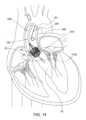
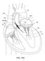
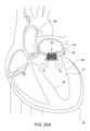
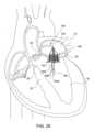
図1は、健康な人間の心臓の断面図を構成している。心臓は、左心房12、右心房14、左心室16、および右心室18を含む、4室の円錐形状の構造体を有している。心臓の左側と右側とを分離する壁は、中隔20と称される。天然の僧帽弁30は、左心房12と左心室16との間に位置決めされている。天然の大動脈弁40は、左心室16と大動脈80との間に位置決めされている。天然の大動脈弁40から延在する大動脈80の最初の部分は、大動脈基部82であり、左心室16の隣接部は、左心室流出路(LVOT:left ventricular outflow tract)22である。Figure 1 constitutes a cross-sectional view of a healthy human heart. The heart has a four-chambered, cone-shaped structure including the
天然の僧帽弁30は、僧帽弁輪32と、弁輪32から下向きに延在する1対の僧帽弁尖34とを含む。適正に動作しているときには、弁尖34は、一緒に機能し、左心房12から左心室14への血流のみを可能する。具体的には、心臓拡張期の間に、左心房12および左心室16の筋肉が拡張するときに、酸素化された血液が、左心房12から僧帽弁30を通って左心室16の中へ流れる。心臓収縮期の間に、左心房12の筋肉が弛緩し、左心室16が接触するとき、左心室16の中の血圧が上昇し、2つの僧帽弁尖34を接合するように促すようになっており、それによって、左心室16からの血流が左心房12に戻ることを防止する。複数の繊維状の索状物(腱索36と称される)が、僧帽弁尖34を左心室16の乳頭筋につなぎ、それらが圧力下で脱出することおよび僧帽弁輪32を通って折り返されることを防止する。The native mitral valve 30 includes a
本明細書で使用されているように、「複数」という用語は、2つ以上を意味している。As used herein, the term "plurality" means two or more.
天然の大動脈弁40は、大動脈弁輪42と、弁輪42から上向きに(大動脈基部82に向けて)延在する3つの大動脈弁尖44とを含む。心臓収縮期の間に、血液は、左心室16から大動脈弁40を通して大動脈80の中へ排出される。天然の僧帽弁30または天然の大動脈弁40のいずれかが適正に機能できないときには、人工交換弁140が、機能性を回復させることを助けることが可能である。The native
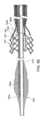
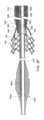
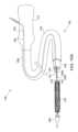
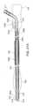
図2は、いくつかの実施形態による、送達アセンブリ100の斜視の図を構成している。送達アセンブリ100は、人工弁140および送達装置102を含むことが可能である。人工弁140は、送達装置102の上にあるか、または、送達装置102に解放可能に連結され得る。送達装置は、その近位端部にハンドル110を含むことが可能であり、ノーズコーンシャフト(本明細書では、NCシャフトとも呼ばれる)108が、ハンドル110から遠位に延在しており、ノーズコーン126が、ノーズコーンシャフト遠位部分(本明細書では、NCシャフト遠位部分とも呼ばれる)120に取り付けられており、送達シャフト106が、NCシャフト118の上に延在しており、随意的に、外側シャフト104が、送達シャフト106の上に延在している。FIG. 2 constitutes a perspective view of a
本明細書で使用されているように、「近位」という用語は、使用時にハンドル110またはハンドル110のオペレータのより近くにある、任意のデバイスまたはデバイスのコンポーネントの側部または端部を一般的に指す。As used herein, the term "proximal" generally refers to the side or end of any device or component of a device that is closer to the
本明細書で使用されているように、「遠位」という用語は、使用時にハンドル110またはハンドル110のオペレータからより遠くにある、任意のデバイスまたはデバイスのコンポーネントの側部または端部を一般的に指す。As used herein, the term "distal" generally refers to the side or end of any device or component of a device that is further from the
本明細書で使用されているように、「人工弁」という用語は、カテーテルの上を患者のターゲット部位へ送達可能な任意のタイプの人工弁を指しており、それは、半径方向に圧縮された(または、クリンプされた)状態と半径方向に拡張された状態との間で、半径方向に拡張可能および圧縮可能である。したがって、人工弁140は、送達の間に、圧縮された状態で、送達装置102によってクリンプされるかまたは保たれ得、次いで、人工弁140が植え込み部位に達すると、拡張された状態に拡張され得る。拡張された状態は、圧縮された状態と、完全に拡張された状態において達される最大直径との間で、弁が拡張することができる直径の範囲を含むことが可能である。したがって、複数の部分的に拡張された状態は、半径方向に圧縮されたまたはクリンプされた状態と最大限に拡張された状態との間の任意の拡張直径に関係することが可能である。As used herein, the term "prosthetic valve" refers to any type of prosthetic valve that can be delivered over a catheter to a target site in a patient, and that is radially expandable and compressible between a radially compressed (or crimped) state and a radially expanded state. Thus, the
本開示の人工弁140は、天然の大動脈弁、天然の僧帽弁、天然の肺動脈弁、および、天然の三尖弁の中に装着されるように構成されている任意の人工弁を含むことが可能である。本開示に説明されている送達アセンブリ100は、送達装置102および人工弁140を含むが、本開示の任意の実施形態による送達装置102は、人工弁以外の他の人工デバイス(たとえば、ステントまたはグラフトなど)の植え込みのために使用され得ることが理解されるべきである。The
人工弁140は、半径方向に圧縮された状態またはクリンプされた状態で弁140をターゲット部位に向けて運搬する送達アセンブリ100を介して、植え込みの部位へ送達され、さまざまな拡張メカニズムを介して弁140を拡張させることによって、天然の解剖学的構造に対して装着され得る。バルーン拡張可能な弁は、一般的に、人工弁の中でバルーンを膨張させ、それによって、所望の植え込み部位の中に人工弁140を拡張させる処置を必要とする。弁が十分に拡張されると、バルーンは収縮され、送達装置102とともに回収される。自己拡張可能な弁は、フレームを含み、フレームは、外側保持カプセル(それは、外側シャフト104の遠位部分または送達シャフト106の遠位部分としても定義され得る)が人工弁に対して近位に引き出されるとすぐに、自動的に拡張するように形状設定されている。機械的に拡張可能な弁は、拡張のために機械的な作動メカニズムに依存する人工弁のカテゴリーである。機械的な作動メカニズムは、通常、複数のアクチュエータアセンブリを含み、複数のアクチュエータアセンブリは、送達装置102のそれぞれの作動アームアセンブリに解放可能に連結されており、作動アームアセンブリは、所望の直径まで人工弁を拡張させるようにアクチュエータアセンブリを作動させるためのハンドル110を介して制御される。アクチュエータアセンブリは、随意的に、弁の位置をロックし、望ましくないその再圧縮、および、アクチュエータアセンブリからの作動アームアセンブリの切り離しを防止することが可能であり、人工弁が植え込みの所望の部位に適正に位置決めされると、送達装置102の回収を可能にすることができる。The
たとえば、大動脈弁輪42に対して装着するための人工大動脈弁を送達するために、僧帽弁輪32に対して装着するための人工僧帽弁を送達するために、または、任意の他の天然の弁輪に対して装着するための人工弁を送達するために、送達アセンブリ100が利用され得る。For example, the
外側シャフト104および送達シャフト106は、互いに対して軸線方向に移動可能であるように構成され得、送達シャフト106に対する外側シャフト104の近位に配向された移動、または、外側シャフト104に対する送達シャフト106の遠位に配向された移動が、外側シャフト104から人工弁140を露出させることができるようになっている。代替的な実施形態において、人工弁140は、送達の間に外側シャフト104の中に収容されていない。したがって、いくつかの実施形態によれば、送達装置102は、外側シャフト104を含まない。The
上述のように、NCシャフト118、送達シャフト106、(機械的に拡張可能な弁のケースでは)作動アームアセンブリのコンポーネント、および、存在するときには、外側シャフト104の近位端部が、ハンドル110に連結され得る。人工弁140の送達の間に、ハンドル110は、オペレータ(たとえば、臨床医または外科医)によって操作され、患者の血管系を通して、送達装置102のコンポーネント(たとえば、ノーズコーンシャフト118、送達シャフト106、および/または外側シャフト104など)を軸線方向に前進または後退させ、ならびに、たとえば、作動アームアセンブリを操作することによって、機械的に拡張可能な弁140'を拡張または収縮させ、ならびに、たとえば、機械的に拡張可能な弁のアクチュエータアセンブリから作動アームアセンブリを解除することによって、送達装置102から人工弁140を切り離すことが可能であり、人工弁が植え込み部位に装着されると、送達装置102を後退させるようになっている。As described above, the
「および/または」という用語は、ここでは包括的であり、「および」ならびに「または」を意味している。たとえば、「送達シャフト106および/または外側シャフト104」は、送達シャフト106、外側シャフト104、および、外側シャフト104を備えた送達シャフト106を包含しており、そのような「送達シャフト106および/または外側シャフト104」は、同様に他のエレメントを含むことも可能である。The term "and/or" is inclusive herein, meaning "and" as well as "or." For example, "
いくつかの実施形態によれば、ハンドル110は、1つまたは複数の動作インターフェース(たとえば、操縦可能なまたは回転可能な調節ノブ、レバー、スライダー、ボタン(図示せず)、および、他の作動メカニズムなど)を含むことが可能であり、1つまたは複数の動作インターフェースは、送達装置102の異なるコンポーネントに動作可能に接続されており、近位方向および遠位方向への送達装置102の軸線方向の移動を作り出すように構成されており、また、さまざまな調節および活性化メカニズムを介して、人工弁140を拡張または収縮させるように構成されている。According to some embodiments, the
いくつかの実施形態によれば、ハンドルは、視覚的なまたは聴覚的な情報および/またはフィードバックを送達装置102のユーザまたはオペレータに提供するように構成されている1つまたは複数の視覚的なまたは聴覚的な情報的エレメントをさらに含む(たとえば、デジタルスクリーン1022(たとえば、LCDスクリーン)、LEDライト1024、およびスピーカー(図示せず)など)。According to some embodiments, the handle further includes one or more visual or auditory informational elements configured to provide visual or auditory information and/or feedback to a user or operator of the delivery device 102 (e.g., a digital screen 1022 (e.g., an LCD screen),
図3Aは、いくつかの実施形態による、拡張された状態の例示的な人工弁140を示している。人工弁140は、流入端部145を画定する流入端部部分144と、流出端部143を画定する流出端部部分142とを含むことが可能である。人工弁140は、流入端部部分144および流出端部部分142を通って延在する弁長手方向軸線141を画定することが可能である。いくつかの場合において、流出端部143は、人工弁140の遠位端部であり、流入端部145は、人工弁140の近位端部である。代替的に、たとえば、弁の送達アプローチに応じて、流出端部は、人工弁の近位端部になることが可能であり、流入端部は、人工弁の遠位端部になることが可能である。3A illustrates an exemplary
本明細書で使用されているように、「流出」という用語は、人工弁の領域を指しており、血液は、そこを通って弁140から流れ、それは、たとえば、弁長手方向軸線141と流出端部143との間にある。As used herein, the term "outflow" refers to the area of the prosthetic valve through which blood flows from the
本明細書で使用されているように、「流入」という用語は、人工弁の領域を指しており、血液は、それを通って弁140の中へ流れ、それは、たとえば、流入端部145と弁長手方向軸線141との間にある。As used herein, the term "inflow" refers to the area of the prosthetic valve through which blood flows into the
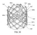
弁140は、相互接続されたストラット148から構成されたフレーム146を含む。フレームは、それに限定されないが、ステンレス鋼、ニッケルベースの合金(たとえば、コバルト-クロムまたはニッケル-コバルト-クロム合金、たとえば、MP35N合金など)、ポリマー、または、それらの組み合わせなどのような、塑性的に拡張可能な材料を含む、さまざまな適切な材料から作製され得る。塑性的に拡張可能な材料から構築されているときには、フレーム146(ひいては、人工弁140)は、送達シャフト106の上で半径方向に圧縮された状態にクリンプされ、次いで、膨張可能なバルーンまたは同等の拡張メカニズムによって患者の内側で拡張され得る。代替的にまたは追加的に、フレーム146は、自己拡張材料、たとえば、それに限定されないが、ニッケルチタン合金(たとえば、ニチノール)などから作製され得る。自己拡張可能な材料から構築されているときには、フレーム146(ひいては、人工弁140)は、半径方向に圧縮された状態にクリンプされ、送達装置102のシャフトまたは同等のメカニズムの中への挿入によって、圧縮された状態で拘束され得る。The
図3Aに示されている例示的な実施形態において、ストラット148の端部部分は、流出端部143において頂点149を形成しており、流入端部145において頂点151を形成している。ストラット148は、流出頂点149と流入頂点151との間に形成された追加的な接合部150において、互いに相互接続され得る。接合部150は、互いに、および/または、流出端部143と流入端部145との間の頂点149、151から、等しく間隔を離してまたは等しくなく間隔を離して配置され得る。ストラット148は、フレーム146の複数のオープンセル147を集合的に画定している。いくつかの実施形態によれば、図3Aの例示的な実施形態に示されているように、ストラット148は、交互の曲げ部を備えて形成され得、曲げ部は、接合部150において互いに溶接され得るかまたはその他の方法で固定され得る。In the exemplary embodiment shown in FIG. 3A, the end portions of the
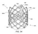
人工弁140は、1つまたは複数の弁尖152(たとえば、3つの弁尖)をさらに含み、1つまたは複数の弁尖152は、流入端部145から流出端部143へ人工弁140を通る血流を調整するように構成されている。三尖弁配置で折り畳むように配置されている3つの弁尖152が、図3Aに図示されている例示的な実施形態に示されているが、人工弁140は、任意の他の数の弁尖152を含むことが可能であることが明確であることになる。弁尖152は、生物学的な材料(たとえば、ウシ心膜または他の供給源からの心膜)、生体適合性の合成材料、または、他の適切な材料に由来する、可撓性の材料から作製されている。弁尖は、直接的に、または、フレーム146に接続されているかもしくはその中に埋め込まれている他の構造的エレメント(たとえば、交連部ポストなど)に取り付けられてのいずれかで、交連部154を介してフレーム146に連結され得る。人工弁に関するさらなる詳細(弁尖がそれらのフレームに装着され得る様式を含む)は、米国特許第6,730,118号、米国特許第7,393,360号、米国特許第7,510,575号、米国特許第7,993,394号、および米国特許第8,252,202号、ならびに、米国特許出願第62/614,299号に説明されており、それらの文献のすべては、参照により本明細書に組み込まれている。The
いくつかの実施形態によれば、人工弁140は、少なくとも1つのスカートまたはシーリング部材(たとえば、図3Aに図示されている例示的な実施形態に示されている内側スカート153など)をさらに含むことが可能である。内側スカート153は、フレーム146の内側表面の上に装着され得、それは、たとえば、シーリング部材として機能し、弁周囲漏出を防止するかまたは減少させるように構成されている。内側スカート153は、フレーム146への弁尖152のためのアンカー固定領域としてさらに機能することが可能であり、および/または、たとえば、弁クリンピングの間に、もしくは、人工弁140の作業サイクルの間に、フレーム146との接触によって引き起こされる可能性のある損傷に対して、弁尖152を保護するように機能することが可能である。追加的にまたは代替的に、人工弁140は、フレーム146の外側表面の上に装着された外側スカート(図示せず)を含むことが可能であり、たとえば、フレーム146と天然の弁輪(人工弁140がそれに対して装着される)の周囲の組織との間に保たれるシーリング部材として機能するように構成することが可能であり、それによって、人工弁140を通過する弁傍漏出のリスクを低減させる。内側スカート153および/または外側スカートのいずれかは、さまざまな適切な生体適合性材料、たとえば、それに限定されないが、さまざまな合成材料(たとえば、PET)または自然の組織(たとえば、心膜の組織)などから作製され得る。According to some embodiments, the
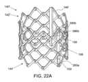
図3Bは、機械的に拡張可能な弁140'を図示しており、機械的に拡張可能な弁140'は、本明細書で上記に説明されている特定のタイプの人工弁140であり、同様のパーツは、ダッシュ記号を有している。いくつかの実施形態によれば、ストラット148'は、格子タイプパターンで配置されている。図3Bに図示されている実施形態では、ストラット148'は、人工弁140'が拡張された位置にあるときに、斜めに位置決めされており、または、弁長手方向軸線141'に対して所定の角度でオフセットされており、弁長手方向軸線141'から半径方向にオフセットされている。ストラット148'は、図3Bに示されているもの以外の角度だけオフセットされ得ることは明らかであろう(たとえば、弁長手方向軸線141'に対して実質的に平行に配向されるなど)。3B illustrates a mechanically expandable valve 140', which is a particular type of
いくつかの実施形態によれば、図3Bにさらに示されているように、フレーム146'は、頂点149'、151'の領域において、および、ストラット148'の接合部150'において、開口部またはアパーチャを含むことが可能である。それぞれのヒンジは、アパーチャを通って延在する締結具(たとえば、リベットまたはピンなど)を介して、ストラット148'のアパーチャが互いに重なり合う場所に含まれ得る。フレーム146'が半径方向に拡張されるかまたは圧縮されるときに、ヒンジは、ストラット148'が互いに対して枢動することを可能にすることができる。According to some embodiments, as further shown in FIG. 3B, the frame 146' can include openings or apertures in the area of the
代替的な実施形態において、ストラットは、それぞれのヒンジを介して互いに連結されていないが、互いに対してその他の方法で枢動可能であるかまたは曲げ可能であり、フレーム拡張または圧縮を可能にするようになっている。たとえば、フレームは、ヒンジなどがない場合にも半径方向に折り畳む/拡張する能力を保ちながら、さまざまなプロセス(たとえば、それに限定されないが、レーザ切断、電鋳、および/または物理蒸着など)を介して、単一のピースの材料(たとえば、金属チューブなど)から形成され得る。In alternative embodiments, the struts are not connected to one another via respective hinges, but are otherwise pivotable or bendable relative to one another to allow for frame expansion or compression. For example, the frame may be formed from a single piece of material (e.g., metal tubing, etc.) via various processes (e.g., but not limited to, laser cutting, electroforming, and/or physical vapor deposition, etc.) while retaining the ability to fold/expand radially in the absence of hinges, etc.
いくつかの実施形態によれば、機械的に拡張可能な弁140'は、複数のアクチュエータアセンブリ156を含み、それは、弁140の拡張を促進させるように構成されており、いくつかの場合において、拡張された状態で弁140'をロックするように構成されており、その非意図的な再圧縮を防止する。図3Bは、3つのアクチュエータアセンブリ156(それは、フレーム146の内側表面に装着されており、フレームフレーム146の内側表面の周りに等しく間隔を置いて配置されている)を図示しているが、異なる数のアクチュエータアセンブリ156が利用され得ること、アクチュエータアセンブリ156がフレーム146にその外側表面の周りに装着され得ること、および、アクチュエータアセンブリ156同士の間の円周方向の間隔は等しくなっていなくてもよいことが明確であるべきである。According to some embodiments, the mechanically expandable valve 140' includes a plurality of
人工弁140および140'の特定の例が、図3Aおよび図3Bにそれぞれ図示されているが、人工弁140は、当技術分野で知られている多くの他の形態をとることが可能であることが理解されよう。本開示の全体を通して、人工弁140への言及は、そうでないことが述べられていない限り、図3Aに図示されている人工弁140の実施形態、および、図3Bに図示されている機械的に拡張可能な弁140'の実施形態を含む、任意のタイプの人工弁に関係する。Specific examples of
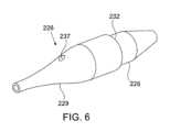
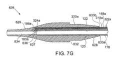
図4Aおよび図4Bは、ノーズコーン外側表面(本明細書では、NC外側表面とも呼ばれる)127を有する例示的な従来のノーズコーン130の斜視の図および側断面図を構成している。ノーズコーン126は、NCシャフト118の遠位端部に接続され得る。ガイドワイヤ(GW)112(図2には示されていないが、たとえば、図12において見ることができる)は、ノーズコーンシャフトガイドワイヤルーメン(本明細書では、NCシャフトGWルーメンとも呼ばれる)122およびノーズコーンガイドワイヤルーメン(本明細書では、NC GWルーメンとも呼ばれる)134を通って延在することが可能であり、送達装置102が、患者の血管系を通してガイドワイヤ112の上を前進され得るようになっている。いくつかの実施形態によれば、ノーズコーン126は、低デュロメーターポリマー、たとえば、Pebax(たとえば、35-shore Pebax)などから作製され得る。4A and 4B constitute a perspective view and a side cross-sectional view of an exemplary
いくつかの実施形態によれば、NCシャフト118は、ノーズコーン近位開口部(本明細書では、NC近位開口部とも呼ばれる)133を通ってノーズコーン126の中へ延在するNCシャフト遠位部分120を含む。ノーズコーン126は、NCシャフト遠位部分120の上にオーバーモールドされるか、または、別個のパーツとして形成され、それに結合され得る。いくつかの実施形態によれば、保持リング(図示せず)が、NCシャフト遠位部分120にリジッドに取り付けられ得、次いで、ノーズコーン126が、保持リングとともにNCシャフト遠位部分120の上にオーバーモールドされ、保持リングの上に保持チャネルを生成させ、それによって、ノーズコーン126とNCシャフト遠位部分120との間にタイトフィットを形成することが可能であり、それは、それらの間の自発的な軸線方向変位を防止するように構成されている。According to some embodiments, the
いくつかの実施形態によれば、ノーズコーンシャフト遠位端部(本明細書では、NSシャフト遠位端部とも呼ばれる)121は、NC近位開口部133の縁部の周りでノーズコーン126の近位表面にリジッドに取り付けられている(実施形態は示されていない)。According to some embodiments, the nosecone shaft distal end (also referred to herein as the NS shaft distal end) 121 is rigidly attached to the proximal surface of the
いくつかの実施形態によれば、NCシャフト遠位部分120は、少なくともノーズコーン遠位端部(本明細書では、NC遠位端部とも呼ばれる)138まで延在しているか、または、NC遠位端部138を越えて延在しており、NC GWルーメン134が、その長さ全体に沿って、NCシャフト遠位部分120の外側表面の一部分を重ね合わせるようになっている(実施形態は示されていない)。ノーズコーン126は、NC近位開口部133およびNC遠位端部138を通って延在するガイドワイヤルーメン長手方向軸線(本明細書では、GWルーメン長手方向軸線とも呼ばれる)135を画定することが可能である。いくつかの場合において、GWルーメン長手方向軸線135および弁長手方向軸線141は、一致することが可能である。According to some embodiments, the NC shaft
いくつかの実施形態によれば、ノーズコーン126は、遠位方向にテーパーの付いた非外傷性のノーズコーン遠位部分(本明細書では、NC遠位部分とも呼ばれる)129を含み、それは、ガイドワイヤ112がそれを通って延在しているときに、ガイドワイヤ112との滑らかな移行を提供するように形成されている。According to some embodiments, the
いくつかの実施形態によれば、ノーズコーン126は、ノーズコーン近位部分(本明細書では、NC近位部分とも呼ばれる)128をさらに含み、ノーズコーン近位部分は、NC遠位部分129の最も近位の端部よりも小さい外径を有することが可能であり、ショルダー部またはノーズコーンリッジ部(本明細書では、NCリッジ部とも呼ばれる)132を画定するようになっている。According to some embodiments, the
NC近位部分128は、図4A~図4Bに図示されているように、ノーズコーン近位円筒状部分(本明細書では、NC近位円筒状部分とも呼ばれる)131を含むことが可能であり、ノーズコーン近位円筒状部分は、NCリッジ部132から近位に延在しており、均一な外径を有しており、望ましくは、外側シャフト104の遠位部分がその上に延在することを可能にするようにサイズ決めされており、また、外側シャフト遠位リップ105(たとえば、図5B~図5Cに示されている)がノーズコーンリッジ部132に当接するかまたは押し付けられることを可能にするようにサイズ決めされている。NC近位部分128は、ノーズコーン近位傾斜部分(本明細書では、NC近位傾斜部分とも呼ばれる)130をさらに含むことが可能であり、ノーズコーン近位傾斜部分は、NC近位円筒状部分131の最も近位の端部におけるより大きい直径から、ノーズコーン126の最も近位の端部におけるより小さい直径へテーパー付きになっている。これは、人工弁140が拡張された後に、人工弁140を通して送達シャフト106の中へノーズコーン126を後退させて戻すことを補助することが可能である。しかし、他の実施形態において、NC近位部分128は、NC近位傾斜部分130を含まなくてもよい。同様に、NC近位部分128は、また、上記に説明されているものとは異なる幾何学的な形状を提供され得る。NC
図5A~図5Cは、人工弁140送達および拡張処置の異なる局面における送達アセンブリ100の遠位部分を示している。植え込みの前に、人工弁140は、送達装置102の上にクリンプされ得る。このステップは、半径方向に圧縮された弁140'を外側シャフト104の中に設置することを含むことが可能である。外側シャフト104の遠位端部部分は、人工弁140の上に延在し、送達装置102の送達構成において、ノーズコーン126に接触することが可能である。したがって、外側シャフト104の遠位端部部分は、送達カプセルとしての役割を果たすことが可能であり、送達カプセルは、患者の血管系を通した送達のために、半径方向に圧縮されたまたはクリンプされた構成で人工弁140を含有するかまたは収容する。図5Aは、クリンプされた人工弁(視界から隠されている)の上に延在している外側シャフト104の遠位部分の例示的な実施形態を示しており、外側シャフト遠位リップ105が、NCリッジ部132に押し付けられている(両方とも図5B~図5Cで見ることができる)。いくつかの実施形態によれば、NC遠位部分129の最大直径は、外側シャフト104の外径に実質的に等しく、ノーズコーン126と外側シャフト104との間の滑らかな移行を提供する。5A-5C show the distal portion of the
外側シャフト104および送達シャフト106は、互いに対して軸線方向に移動可能となるように構成され得、送達シャフト106に対する外側シャフト104の近位に配向された移動、または、外側シャフト104に対する送達シャフト106の遠位に配向された移動が、図5Bに示されているように、外側シャフト104から人工弁140を露出させることができるようになっている。代替的な実施形態において、人工弁140は、送達の間に外側シャフト104の中に収容されていない。したがって、いくつかの実施形態によれば、送達装置102は、外側シャフト104を含まない。The
いくつかの実施形態によれば、人工弁140は、機械的に拡張可能な弁140'であり、それは、複数のアクチュエータアセンブリ156を含み、複数のアクチュエータアセンブリ156は、フレーム146に固定されており、ハンドル110によって動作可能な適当な作動制御メカニズムを介して、フレーム146を半径方向に拡張および/または圧縮するように構成されている。According to some embodiments, the
図5Cは、拡張された状態の例示的な機械的に拡張可能な弁140'を示しており、送達装置102は、ハンドル110から送達シャフト106を通って延在する複数の作動アームアセンブリ160をさらに含む。作動アームアセンブリ160は、一般的に、作動部材155およびサポートスリーブ157を含むことが可能であり、作動部材155は、それらの遠位端部において、それぞれのアクチュエータアセンブリ156に解除可能に連結されており、サポートスリーブ157は、それぞれの作動部材155の周りに配設されている(作動部材155およびサポートスリーブ157は、たとえば、図9Dの断面図で見ることができる)。それぞれの作動部材155は、それをカバーするサポートスリーブ157に対して軸線方向に移動可能であり得る。そうでないことが述べられていない限り、弁尖132、132'およびスカート136、136'は、明確にする目的のために、図の全体を通して図から省略されている。5C illustrates an exemplary mechanically expandable valve 140' in an expanded state, with the
いくつかの実施形態によれば、それぞれのアクチュエータアセンブリ156は、内側部材159を含み、内側部材159は、外側部材158のルーメンを通って部分的に延在することが可能である。内側部材は、その一方の端部(たとえば、流入端部部分144'に沿った流入頂点151'または別の接合部150'など)において、フレーム146'に取り付けられ得る。外側部材は、その反対側端部(たとえば、流出端部部分142'に沿った流出頂点149'または別の接合部150'など)において、フレーム146'に取り付けられ得る。According to some embodiments, each
いくつかの実施形態によれば、作動アームアセンブリ160は、人工弁140'に解除可能に連結するように構成されており、また、半径方向に圧縮された状態と半径方向に拡張された状態との間で、人工弁140'を移動させるように構成されている。たとえば、作動アームアセンブリ160の作動部材155は、その遠位端部において、内側部材159の近位端部における受け入れ用ネジ山付きボアにネジ式に取り付けられ得る。作動部材155をカバーするサポートスリーブ157の遠位縁部は、外側部材158の近位端部に当接するかまたは係合することが可能であり、外側部材158がサポートスリーブ157を越えて近位に移動することを防止するようになっている。According to some embodiments, the
フレーム146'(ひいては、人工弁140')を半径方向に拡張させるために、サポートスリーブ157は、外側部材158に対してしっかりと保持され得る。次いで、作動部材155は、近位に配向された方向に引っ張られ得る。サポートスリーブ157は、外側部材158に対して保持されており、外側部材158は、流出頂点149'に接続されているので、フレーム146'の流出端部143'は、サポートスリーブ157に対して移動することを防止される。そうであるので、近位に配向された方向への作動部材155の移動は、同じ方向への内側部材159の移動を引き起こし、それによって、フレーム146'を軸線方向に短縮して半径方向に拡張させることが可能である。より具体的には、内側部材159が外側部材158の中を(たとえば、近位に配向された方向に)軸線方向に移動されるときには、内側部材159が取り付けられている接合部150'が、それに沿って、外側部材158が取り付けられている反対側の接合部に向けて、同じ方向に移動する。そして、これは、フレーム146'を軸線方向に短縮して半径方向に拡張させる。To radially expand the frame 146' (and thus the prosthetic valve 140'), the
人工弁140'の所望の直径に達すると、作動部材155は、内側部材159からそれを回して外すように回転され得る。この回転は、作動部材155の遠位ネジ山付き部分と内側部材(図示せず)のネジ山付きボアとの間で離脱させる役割を果たし、作動アームアセンブリ160が引き離されて患者の身体から送達装置102とともに後退されることを可能にし、人工弁140'が患者の中に植え込まれたままにする。Once the desired diameter of the prosthetic valve 140' is reached, the
フレーム146'の半径方向の拡張は、近位に配向された方向に外側部材158に対して内側部材159を軸線方向に移動させることによって実現可能であるが、同様のフレーム拡張は、遠位に配向された方向に内側部材159に対して外側部材158を軸線方向に押すことによって実現され得ることが理解されよう。そのうえ、図5Cの図示されている実施形態は、フレーム146'の流出端部部分142'に固着された外側部材158、および、フレーム146'の流入端部部分144'に固着された内側部材159を示しているが、代替的な実施形態において、外側部材158は、フレーム146'の流入端部部分144'に固着され得、一方では、内側部材159は、フレーム146'の流出端部部分142'に固着され得る。It will be appreciated that while radial expansion of the frame 146' can be achieved by axially moving the
いくつかの実施形態によれば、ハンドル110は、制御メカニズムを含むことが可能であり、制御メカニズムは、操縦可能なまたは回転可能なノブ、レバー、およびボタンなどを含むことが可能であり、それらは、オペレータによって手動で制御可能であり、送達装置102の異なるコンポーネントの軸線方向のおよび/または回転可能な移動を作り出す。たとえば、ハンドル110は、1つまたは複数の手動の制御ノブ(たとえば、オペレータによって回転されるときに作動アームアセンブリ160の作動部材155を引っ張るのに効果的な手動で回転可能な制御ノブなど)を含むことが可能である。According to some embodiments, the
他の実施形態によれば、ハンドル110の中のおよび/または送達装置102の他のコンポーネントの中の制御メカニズムは、電気的に、空気圧式に、および/または液圧式に制御され得る。いくつかの実施形態によれば、ハンドル110は、1つまたは複数の電気モーターを収容することが可能であり、1つまたは複数の電気モーターは、たとえば、ハンドル110の上のボタンまたはスイッチを押圧することなどによって、オペレータによって作動され、送達装置102のコンポーネントの移動を作り出すことが可能である。たとえば、ハンドル110は、作動アームアセンブリ160のコンポーネントの線形移動を作り出すように動作可能な1つもしくは複数のモーター、および/または、内側部材159から作動部材155を切り離すために、作動部材155の回転移動を作り出すように動作可能な1つもしくは複数のモーターを含むことが可能である。いくつかの実施形態によれば、1つまたは複数の手動のまたは電気的な制御メカニズムは、作動部材155のすべての同時の線形移動および/または回転移動を作り出すように構成されている。According to other embodiments, the control mechanisms in the
特定の作動メカニズムが上記に説明されているが、他のメカニズムが用いられ、たとえば、ネジ式のまたは他の係合メカニズムを介して、作動アセンブリの内側部材と外側部材との間の相対的な移動を推進することが可能である。機械的に拡張可能な弁およびその送達システムの構造および動作に関するさらなる詳細は、米国特許第9、827、093号、米国特許出願公開第2019/0060057号、米国特許出願公開第2018/0153689号、および米国特許出願公開第2018/0344456号、ならびに、米国特許出願第62/870,372号および米国特許出願第62/776,348号に説明されており、それらの文献のすべては、参照により本明細書に組み込まれている。Although certain actuation mechanisms are described above, other mechanisms can be used to drive relative movement between the inner and outer members of the actuation assembly, for example, via a threaded or other engagement mechanism. Further details regarding the structure and operation of the mechanically expandable valve and its delivery system are described in U.S. Pat. No. 9,827,093, U.S. Patent Application Publication No. 2019/0060057, U.S. Patent Application Publication No. 2018/0153689, and U.S. Patent Application Publication No. 2018/0344456, as well as U.S. Patent Application No. 62/870,372 and U.S. Patent Application No. 62/776,348, all of which are incorporated herein by reference.
いくつかのケースでは、たとえば、再位置決め処置もしくは再交差処置(re-crossing procedure)が実施されることを可能にするために、および/または、人工弁拡張直径の再調節を可能にするために、拡張された人工弁140を現場で再圧縮することが望ましい可能性がある。いくつかの実施形態によれば、送達装置102は、再圧縮メカニズムをさらに含み、再圧縮メカニズムは、部分的にまたは完全に拡張された人工弁140の再圧縮を促進させるように構成されている。図5Cは、機械的に拡張可能な人工弁140'を圧縮するように構成されている例示的な再圧縮メカニズムを示しているが、そのメカニズムは、他のタイプの人工弁140にも同様に適用され得る。In some cases, it may be desirable to recompress the expanded
いくつかの実施形態によれば、再圧縮メカニズムは、可撓性の再圧縮部材166を含み、再圧縮部材166は、(図9Fに示されているメインルーメン263と同様の)再圧縮シャフトメインルーメン163を通って延在している。再圧縮シャフト162は、送達シャフト106のルーメンを通って延在している。再圧縮部材166は、可撓性のワイヤ、ケーブル、および縫合糸などから形成され得る。可撓性の再圧縮部材166は、再圧縮シャフト162の遠位端部に形成された開口部を通って遠位に延在するように構成されており、遠位ループ167を形成しており、遠位ループ167は、人工弁140'を取り巻くことが可能であり、または、人工弁140'に取り付けられている作動アームアセンブリ160の周りに、および/もしくは、作動アームアセンブリ160同士の間に延在することが可能である。According to some embodiments, the recompression mechanism includes a
図5Cの例示的な実施形態において、遠位ループ167は、作動アームアセンブリ160に連結されており、作動アームアセンブリ160同士の間に延在している。いくつかの実施形態によれば、それぞれの作動アームアセンブリ160は、ループ取り付け部材161を含む。たとえば、それぞれの作動アームアセンブリ160のサポートスリーブ157は、その遠位部分において、作動アームアセンブリ160が人工弁140'に取り付けられているときには人工弁140'に近接して、ループ取り付け部材161を含むことが可能である。ループ取り付け部材161は、アイレット、フック、リング、クリップ、サポートスリーブ157の中のアパーチャ、または、それらの間での遠位ループ167の拡張を保つようにおよび可能にするように構成されている任意の他の構造的エレメントの形態で提供され得る。図5Cに図示されている特定の実施形態では、遠位ループ167は、アイレットの形態のループ取り付け部材161を通って延在している。In the exemplary embodiment of FIG. 5C, the
いくつかの実施形態によれば、再圧縮部材166と再圧縮シャフト162との間の軸線方向への相対的な移動は、作動アームアセンブリ160に接続されて作動アームアセンブリ160同士の間に延在している遠位ループ167を締め付けるのに効果的であり、それによって、人工弁140'を半径方向に圧縮する。たとえば、ハンドル110は、再圧縮部材166を引っ張るように操作され得、内向きに方向付けられた力を作動アームアセンブリ160に印加するようになっている。作動アームアセンブリ160がアクチュエータアセンブリ156に取り付けられている限り、弁140'のフレーム146'は、また、比例して半径方向に圧縮される。According to some embodiments, the relative axial movement between the
代替的な実施形態において、遠位ループ167は、弁140'自身を取り巻き、作動アームアセンブリ160を介する代わりに、遠位ループ167を締め付けながら、それを直接的に圧縮することが可能である(実施形態は示されていない)。In an alternative embodiment, the
上述のように、再圧縮メカニズムは、代替的に、他のタイプの人工弁140(たとえば、自己拡張可能な弁(図示せず)など)とともに利用され得る。自己拡張可能な弁は、可撓性のフレームを含み、弁は、可撓性のフレームは、送達の間にクリンプされた状態で人工弁を保つ送達カプセルから人工弁が解放されるときに、その拡張された自由状態まで拡張するように構成されている。そのような実施形態では、遠位ループ167は、機械的に拡張可能な弁の代わりに自己拡張可能な弁を取り巻くことが可能であり、それは、再圧縮部材166がハンドル110を介して引っ張られるときに、それを圧縮するように構成されている。弁再拡張は、再圧縮部材166が張力をかけられた状態から解放されるときに許容され得る(実施形態は示されていない)。As discussed above, the recompression mechanism may alternatively be utilized with other types of
いくつかの実施形態によれば、送達装置102は、第1のセンサ180aをさらに含み、第1のセンサ180aは、ノーズコーンの中に保たれており、第1のセンサ180aが、ノーズコーン側部開口部を通してノーズコーンの周囲環境に露出されるようになっており、すなわち、ノーズコーンガイドワイヤルーメンを通してノーズコーンの周りの血流に露出されるようになっている。第1のセンサ180aは、生理学的なフロー関係の特性(たとえば、血圧および/または血流など)を測定するように構成されている。According to some embodiments, the
図6は、いくつかの実施形態による、第1のセンサ180aをその中に保つように構成されているノーズコーン226の斜視の図を構成している(たとえば、図7Aに示されている)。ノーズコーン226は、第1のセンサ180a(それは、ノーズコーン226の中に保たれ得る)への横断方向のアクセスを提供するためのノーズコーン横方向ポート(本明細書では、NC横方向ポートとも呼ばれる)236(たとえば、図7Aに示されている)をさらに含むことを除いて、構造および機能に関してノーズコーン126と同様である。第1のセンサ180aは、NC横方向ポート236と位置合わせされノーズコーンの中に位置決めされている。図6に示されているように、NC横方向ポート236は、その端部において、ノーズコーンポート開口部(本明細書では、NCポート開口部とも呼ばれる)237において終端することが可能であり、第1のセンサ180aが、NCポート開口部237と位置合わせされて、NC横方向ポート236の中に位置決めされるようになっている。いくつかの実施形態によれば、NCポート開口部237は、NC外側表面227に形成されており、第1のセンサ180aが、NCポート開口部237と位置合わせされて位置決めされ得るようになっている。ノーズコーン226の他のエレメントは、本質的に、ノーズコーン126のエレメントと同様であり、同様の参照番号は、図の全体を通して同様のパーツを指しており、したがって、さらには説明されないことになる。FIG. 6 constitutes a perspective view of a
第1のセンサ180aなどのようなセンサに対して「ノーズコーンの中に保たれる」という用語は、ノーズコーンの外側表面とノーズコーン長手方向軸線との間に境界を定められた体積の中に、センサが位置決めされていることを指す。たとえば、第1のセンサ180aがノーズコーン226の中に保たれていることは、第1のセンサ180aがNC外側表面227とGWルーメン長手方向軸線235との間に位置決めされていることを指す。いくつかの実施形態によれば、第1のセンサ180aは、第1のセンサ180aのいずれの部分もNC外側表面227から離れるように半径方向に突出していない場合に、ノーズコーン226の中に保たれているものとして定義される。The term "held within the nosecone" for a sensor, such as the
有利には、第1のセンサ180aがノーズコーン226の中に保たれている構成は、NC外側表面227が滑らかなままであることを保証し、それが患者の血管系の中を容易にナビゲートすることを可能にする。Advantageously, the configuration in which the
いくつかの実施形態によれば、NC遠位部分229は、NC横方向ポート236を含み、NCポート開口部237が、図6に示されているように、NC遠位部分229の外側表面に形成されるようになっている。According to some embodiments, the NC
図7A~図7Gは、ノーズコーンの中に保たれている第1のセンサ180aを含む、送達装置102のノーズコーンおよびNCシャフトの異なる構成を示している。図7Aは、ノーズコーン226の中に保たれている第1のセンサ180aの例示的な構成を示している。いくつかの実施形態によれば、図7Aに示されているように、第1のセンサ180aは、NCシャフト遠位部分120の外側表面に取り付けられており、また、第1のセンサ180aがNC横方向ポート236の中にNC横方向ポート236と位置合わせされて位置決めされるように、より具体的には、NCポート開口部237と位置合わせされて位置決めされるように位置決めされている。いくつかの実施形態によれば、NC横方向ポート236は、図7Aに示されているように、NC GWルーメン234に実質的に直交している。7A-7G show different configurations of the nosecone and NC shaft of the
いくつかの実施形態によれば、センサは、アクティブ面およびパッシブ面を含む。たとえば、第1のセンサ180aは、第1のアクティブ面186aと、反対側の第1のパッシブ面187aとを含み、第1のアクティブ面186aは、測定領域に方向付けられた第1のセンサ180aの側部または表面として定義されており、第1のパッシブ面187aは、送達アセンブリ100のコンポーネントに面しおよび/またはそれに取り付けられている第1のセンサ180aの側部または表面であることが可能である。図7Aの例示的な実施形態において、第1のセンサ180aは、その第1のパッシブ面187aにおいて、NCシャフト遠位部分120の外側表面に取り付けられている。According to some embodiments, the sensor includes an active surface and a passive surface. For example, the
いくつかの実施形態によれば、第1のセンサ180aは、ノーズコーン226の中に保たれており、第1のパッシブ面187aがGWルーメン長手方向軸線235に向けて配向されるようになっており、一方では、第1のアクティブ面186aがNCポート開口部237に向けて配向されており、随意的に、NCポート開口部237と同一平面上にあるようになっている。According to some embodiments, the
いくつかの実施形態によれば、NC横方向ポート236の長さは、第1のセンサ180aの高さよりも大きく、第1のアクティブ面186aが、(たとえば、図7Aに示されているように)NC外側表面127に対して半径方向内向きに位置決めされるようになっている。代替的な実施形態によれば、NC横方向ポート236の長さは、第1のセンサ180aの高さに実質的に等しく、第1のアクティブ面186aが、(たとえば、図7Cに示されているように)NC外側表面127と同一平面上にあるようになっている。第1のセンサ180aの高さは、第1のパッシブ面187aと第1のアクティブ面186aとの間の距離として定義される。According to some embodiments, the length of the
いくつかの実施形態によれば、第1の送信ライン168aが、第1のセンサ180aに連結されており、そこから近位にハンドル110に向けて延在している。いくつかの実施形態によれば、第1の送信ライン168aは、電力を第1のセンサ180aに送達するように構成されている。いくつかの実施形態によれば、第1の送信ライン168aは、(たとえば、ハンドル110の中の)近位電源に接続されており、近位電源は、電力を提供し、第1のセンサ180aを動作させるように構成されている。According to some embodiments, the
いくつかの実施形態によれば、第1の送信ライン168aは、第1のセンサ180aからおよび/または第1のセンサ180aへ、信号(たとえば、電気信号および/または光学信号)を送達するように構成されている。いくつかの実施形態によれば、第1の送信ライン168aは、プロセッサーを含む内部制御ユニット1010(たとえば、図16Aに概略的に示されている)に接続されている。内部制御ユニット1010は、ハンドル110の中に埋め込まれ得、第1のセンサ180aから信号を受信するように、および/または、それへ信号を送信するように構成されている。According to some embodiments, the
いくつかの実施形態によれば、第1の送信ライン168aは、直接的にまたは間接的に(たとえば、内部制御ユニット1010を介して)、近位通信コンポーネント1030(たとえば、図16Aに概略的に示されている)に接続されている。近位通信コンポーネント1030は、内部制御ユニット1010に動作可能に連結され得る。近位通信コンポーネント1030は、トランスミッター、レシーバー、トランシーバー、および/または、データ通信ソケットを含むことが可能であり、それは、ハンドル110の中に埋め込まれており、送達アセンブリ100の外部にあるコンポーネントおよび/もしくはデバイスから信号を受信するように、ならびに/または、それへ信号を送信するように構成されている。According to some embodiments, the
いくつかの実施形態によれば、第1の送信ライン168aは、ノーズコーンシャフト外側表面(本明細書では、NCシャフト外側表面とも呼ばれる)125に取り付けられているか、または、たとえば、螺旋状のパターン(図示せず)でその周りに巻き付けられており、第1のセンサ180aからハンドル110へ延在しており、随意的に、ハンドル110の中へさらに延在している。According to some embodiments, the
いくつかの実施形態によれば、図7Aに示されているように、NC近位開口部233は、NCシャフト118および第1の送信ライン168aの両方がそれを通って延在することを可能にするように形状決めおよび寸法決めされている。According to some embodiments, as shown in FIG. 7A, the NC
いくつかの実施形態によれば、NCシャフトは、マルチルーメンシャフトであり、少なくとも1つのノーズコーンシャフトガイドワイヤルーメンおよび少なくとも1つのノーズコーンシャフトセンサルーメンを含む。According to some embodiments, the NC shaft is a multi-lumen shaft and includes at least one nosecone shaft guidewire lumen and at least one nosecone shaft sensor lumen.
図7Bは、ノーズコーン226の中に保たれている第1のセンサ180aの別の例示的な構成を示している。図7Bの実施形態では、ノーズコーン226は、NCシャフト218のNCシャフト遠位部分220に取り付けられている。NCシャフト218は、それがマルチルーメンシャフトとして提供されることを除いて、構造および機能に関してNCシャフト118と同様であり、マルチルーメンシャフトは、NCシャフトGWルーメン222に加えて、ノーズコーンシャフトセンサルーメン(本明細書では、NCシャフトセンサルーメンとも呼ばれる)223を含み、また、NCシャフト遠位部分220において、ノーズコーンシャフト側部開口部(本明細書では、NCシャフト側部開口部とも呼ばれる)224を含む。NCシャフト側部開口部224は、NCシャフトセンサルーメン223から半径方向外向きに延在している。NCシャフト側部開口部224は、ノーズコーンシャフト遠位端部(本明細書では、NCシャフト遠位端部とも呼ばれる)221に隣接しているか、または、ノーズコーンシャフト遠位端部221から軸線方向に離れるように間隔を置いて配置され得る。NCシャフト218の他のエレメントは、NCシャフト118のエレメントと本質的に同様であり、同様の参照番号は、図の全体を通して同様のパーツを指しており、したがって、さらには説明されないことになる。いくつかの実施形態によれば、NCシャフトセンサルーメン223は、図7Bに示されているように、NCシャフト遠位端部221において閉鎖端になっている。7B illustrates another exemplary configuration of the
いくつかの実施形態によれば、第1のセンサ180aは、NCシャフト側部開口部224と位置合わせされて、NCシャフトセンサルーメン223の中に位置決めされている。いくつかの実施形態によれば、第1のセンサ180aは、NCシャフトセンサルーメン223の内側表面に取り付けられている。いくつかの実施形態によれば、第1のセンサ180aは、その第1のパッシブ面187aにおいて、NCシャフトセンサルーメン223の内側表面に取り付けられており、一方では、第1のアクティブ面186aは、NCシャフト側部開口部224に向けて配向されており、随意的に、NCシャフト側部開口部224と同一平面上にある。According to some embodiments, the
NCシャフト側部開口部224は、NC横方向ポート236と位置合わせされ、NC横方向ポート236に流体連通しており、使用時に第1のセンサ180a(とりわけ、第1のアクティブ面186a)をNCポート開口部237に隣接する血流に露出させるように構成された連続的なチャネルまたはポートを一緒に形成している。The NC
いくつかの実施形態によれば、第1の送信ライン168aは、第1のセンサ180aからハンドル110に向けて、NCシャフトセンサルーメン223を通って軸線方向に延在している。いくつかの実施形態によれば、第1の送信ライン168aは、NCシャフトセンサルーメン223の内側表面に取り付けられている。いくつかの実施形態によれば、NC近位開口部233は、マルチルーメンNCシャフト218がそれを通って延在することを可能にするように形状決めおよび寸法決めされている。According to some embodiments, the
いくつかの実施形態によれば、送達装置102は、少なくとも1つのセンサシャフト318をさらに含み、少なくとも1つのセンサシャフト318は、ハンドル110から遠位に延在しており、その中に取り付けられている(または、保たれている)少なくとも1つのセンサを担持するように構成されている。少なくとも1つのセンサは、センサシャフト遠位部分320に取り付けられ得る。いくつかの実施形態によれば、少なくとも1つのセンサシャフトは、第1のセンサシャフト318aであり、第1のセンサシャフト318aは、第1のセンサシャフト遠位部分320aを含み、第1のセンサシャフトルーメン322aを画定している。いくつかの実施形態によれば、第1のセンサシャフト318aは、送達シャフト108のルーメンを通って軸線方向に延在している。いくつかの実施形態によれば、第1のセンサシャフト遠位部分320aは、ノーズコーンに取り付けられている。According to some embodiments, the
図7Cは、ノーズコーン326の中に保たれている第1のセンサ180aの例示的な構成を示しており、第1のセンサ180aは、第1のセンサシャフト遠位部分320aに取り付けられている。ノーズコーン326は、ノーズコーン326が(NCシャフト遠位部分120を介して)NCシャフト118および(第1のセンサシャフト遠位部分320aを介して)第1のセンサシャフト318aの両方に取り付けられていることを除いて、構造および機能に関してノーズコーン226と同様である。具体的には、NCシャフト118および第1のセンサシャフト318aは、第1のノーズコーン近位開口部333aおよび第2のノーズコーン近位開口部333bをそれぞれ通って、ノーズコーン326の中へ延在している。ノーズコーン326の他のエレメントは、ノーズコーン226のエレメントと本質的に同様であり、同様の参照番号は、図の全体を通して同様のパーツを指しており、したがって、さらには説明されないことになる。7C shows an exemplary configuration of a
いくつかの実施形態によれば、第1のセンサシャフト318aは、第1のセンサシャフト遠位部分320aにおいて、第1のセンサシャフト側部開口部324aを含む。第1のセンサシャフト側部開口部324aは、第1のセンサシャフト遠位端部321aに隣接しているか、または、第1のセンサシャフト遠位端部321aから軸線方向に離れるように間隔を置いて配置され得る。いくつかの実施形態によれば、第1のセンサシャフトルーメン322aは、図7Cに示されているように、第1のセンサシャフト遠位端部321aにおいて閉鎖端になっている。代替的に、第1のセンサシャフト318aは、遠位軸線方向開口部(図示せず)、たとえば、第1のセンサ180aがそれを通って延在することができる遠位軸線方向開口部を含むことが可能である。According to some embodiments, the
図7Cに示されている第1のセンサ180aは、第1のセンサシャフト側部開口部324aと位置合わせされて、第1のセンサシャフトルーメン322aの中に位置決めされている。いくつかの実施形態によれば、第1のセンサ180aは、第1のセンサシャフトルーメン322aの内側表面に取り付けられている。いくつかの実施形態によれば、第1のセンサ180aは、その第1のパッシブ面187aにおいて、第1のセンサシャフトルーメン322aの内側表面に取り付けられており、一方では、第1のアクティブ面186aは、第1のセンサシャフト側部開口部324aに向けて配向されている。図7Cに図示されている実施形態では、第1のアクティブ面186aは、NC外側表面327と実質的に同一平面上にある。The
第1のセンサシャフト側部開口部324aは、NC横方向ポート236と位置合わせされており、それらの間に流体接続を形成するようになっており、使用時に第1のセンサ180aをNCポート開口部237に隣接する血流に露出させるように構成された連続的なチャネルまたはポートを一緒に形成している。The first sensor
いくつかの実施形態によれば、第1の送信ライン168aは、第1のセンサ180aからハンドル110に向けて、第1のセンサシャフトルーメン322aを通って軸線方向に延在している。いくつかの実施形態によれば、第1の送信ライン182aは、第1のセンサシャフトルーメン322aの内側表面に取り付けられている。いくつかの実施形態によれば、第2のノーズコーン近位開口部333bは、第1のセンサシャフト318aがそれを通って延在することを可能にするように形状決めおよび寸法決めされている。According to some embodiments, the
いくつかの実施形態によれば、第1のセンサ180aは、NC外側表面の周りの周囲環境、NC GWルーメン、またはその両方のいずれかにそれが露出され得るように、ノーズコーンの中に保たれている。According to some embodiments, the
図7Dは、第1のセンサ180aの例示的な構成を示しており、第1のセンサ180aは、ノーズコーン426の中に保たれており、第1のセンサ180aが、NC外側表面427の周りの周囲環境、NC GWルーメン434、またはその両方のいずれかにそれが露出され得るようになっている。図7Dの実施形態では、ノーズコーン426は、NCシャフト418のNCシャフト遠位部分420に取り付けられている。NCシャフト418は、マルチルーメンシャフトであり、それは、NCシャフトセンサルーメン423がNCシャフト遠位端部421において開放端になっていることを除いて、構造および機能に関してマルチルーメンNCシャフト218と同様である。NCシャフト418は、NCシャフト側部開口部を含んでもよくまたは含まなくてもよい。図7Dの例示的な実施形態において、NCシャフト418は、NCシャフト側部開口部を欠いている。NCシャフト418の他のエレメントは、NCシャフト218のエレメントと本質的に同様であり、同様の参照番号は、図の全体を通して同様のパーツを指しており、したがって、さらには説明されないことになる。FIG. 7D illustrates an exemplary configuration of the
ノーズコーン426は、NC横方向ポート436がNC GWルーメン434からNC外側表面427へ半径方向に延在していることを除いて、構造および機能に関してノーズコーン226と同様である。NCシャフト418は、NC横方向ポート436の中へ突出することなく、NC横方向ポート436においてまたはその近位において終端することが可能である。たとえば、NCシャフト遠位端部421は、NC横方向ポート436の近位縁部と同一平面上にあることが可能である。ノーズコーン426の他のエレメントは、ノーズコーン226のエレメントと本質的に同様であり、同様の参照番号は、図の全体を通して同様のパーツを指しており、したがって、さらには説明されないことになる。The
いくつかの実施形態によれば、第1のセンサ180aは、NC横方向ポート436の中に位置決めされ得る。たとえば、第1の送信ライン168aは、NCシャフトセンサルーメン423を通って延在することが可能であり、第1のセンサ180aが、NCシャフト遠位端部421の遠位に延在することができるようになっている。According to some embodiments, the
NC横方向ポート436の中に位置決めされている第1のセンサ180aは、NC外側表面427の周りの周囲環境、NC GWルーメン434、または、その両方に露出され得る。いくつかの実施形態によれば、図7Dに図示されているように、第1のアクティブ面186aは、NC外側表面427に向けて配向されており、一方では、第1のパッシブ面187aは、NC GWルーメン434に向けて配向されている。いくつかの実施形態によれば、第1のアクティブ面186aは、NC GWルーメン434に向けて配向されており、一方では、第1のパッシブ面187aは、NC外側表面427に向けて配向されている。いくつかの実施形態によれば、第1のセンサ180aは、少なくとも2つの直径方向に対向する第1のアクティブ面を含み、一方のアクティブ面がNC GWルーメン434に向けて配向されるようになっており、反対側のアクティブ面がNC GWルーメン434に向けて配向されるようになっている。いくつかの実施形態によれば、第1のセンサ180aは、たとえば、ハンドル110によって操作可能な第1の送信ライン186を介して、その対称軸線の周りに回転され得、第1のアクティブ面186aの配向が、NC外側表面427とNC GWルーメン434との間切り替えられ得るようになっている。The
いくつかの実施形態によれば、第1の送信ライン168aまたは第1のセンサ180aのいずれも、ノーズコーンシャフト418にリジッドに取り付けられておらず、むしろ、これらのエレメントは、ノーズコーンシャフト418に対して軸線方向に移動可能となるように構成されている。そのような実施形態は、たとえば、第1のセンサ180aの除去または交換が必要とされる場合には、NCシャフトセンサルーメン423を通した第1のセンサ180aの挿入および後退を可能にすることができる。According to some embodiments, neither the
いくつかの実施形態によれば、送達装置102は、第1のセンサ180aを含み、第1のセンサ180aは、ノーズコーンの中に保たれており、第1のセンサ180aが、NC GWルーメンに露出されており、NC外側表面には露出されないようになっている。「NC GWルーメン」という用語は、NC遠位端部からNC近位開口部へ延在するそのようなルーメンの長さ全体を指し、それは、少なくともノーズコーンに取り付けられているNCシャフト遠位部分の一部分に沿って、NCシャフトGWルーメンの一部分と一致することが可能であることが明確であることになる。According to some embodiments, the
図7Eは、第1のセンサ180aの例示的な構成を示しており、第1のセンサ180aは、ノーズコーン126の中に保たれており、第1のセンサ180aが、NC GWルーメン134に露出されるようになっている。図7Eに示されている例示的な構成では、ノーズコーン126は、マルチルーメンNCシャフト518のNCシャフト遠位部分520に取り付けられている。NCシャフト518は、NCシャフト側部開口部524がNCシャフトセンサルーメン523からNC GWルーメン134に向けて半径方向内向きに延在していることを除いて、構造および機能に関してノーズコーンシャフト218と同様である。NCシャフト518の他のエレメントは、NCシャフト218のエレメントと本質的に同様であり、同様の参照番号は、図の全体を通して同様のパーツを指しており、したがって、さらには説明されないことになる。7E shows an exemplary configuration of the
いくつかの実施形態によれば、第1のセンサ180aは、NCシャフト側部開口部524と位置合わせされて、NCシャフトセンサルーメン523の中に位置決めされている。いくつかの実施形態によれば、第1のセンサ180aは、NCシャフトセンサルーメン523の内側表面に取り付けられている。いくつかの実施形態によれば、第1のセンサ180aは、その第1のパッシブ面187aにおいて、NCシャフトセンサルーメン523の内側表面に取り付けられており、一方では、第1のアクティブ面186aは、NCシャフト側部開口部524に向けて配向されており、随意的に、NCシャフト側部開口部524と同一平面上にある。より具体的には、第1のアクティブ面186aは、NC GWルーメン134に向けて配向されている。According to some embodiments, the
いくつかの実施形態によれば、第1のセンサ180aは、ノーズコーン126の中に保たれており、第1のアクティブ面186aが、GWルーメン長手方向軸線135に向けて配向されるようになっており、一方では、第1のパッシブ面187aが、NC外側表面127に向けて配向されるようになっている。According to some embodiments, the
いくつかの実施形態によれば、第1の送信ライン168aは、第1のセンサ180aからハンドル110に向けて、NCシャフトセンサルーメン523を通って軸線方向に延在している。いくつかの実施形態によれば、第1の送信ライン168aは、NCシャフトセンサルーメン523の内側表面に取り付けられている。いくつかの実施形態によれば、NC近位開口部133は、マルチルーメンNCシャフト518がそれを通って延在することを可能にするように形状決めおよび寸法決めされている。According to some embodiments, the
図7Fは、ノーズコーン526の中に保たれている第1のセンサ180aの別の例示的な構成を示している。図7Fの実施形態では、ノーズコーン526は、NCシャフト418のNCシャフト遠位部分420に取り付けられている。ノーズコーン526は、NC横方向ポート536がNC GWルーメン534からNC外側表面527に向けて半径方向に延在しているが、NC外側表面527までは延在していないことを除いて、構造および機能に関してノーズコーン426と同様である。したがって、NC横方向ポート536は、NCポート開口部537において、NC GWルーメン534に流体連通しており、NCポート開口部537は、それらの間に形成されている。ノーズコーン526の他のエレメントは、ノーズコーン426のエレメントと本質的に同様であり、同様の参照番号は、図の全体を通して同様のパーツを指しており、したがって、さらには説明されないことになる。7F illustrates another exemplary configuration of the
いくつかの実施形態によれば、第1のセンサ180aは、NC横方向ポート536の中に位置決めされ得る。NC横方向ポート536の中に位置決めされている第1のセンサ180aは、NC GWルーメン534に露出され得る。According to some embodiments, the
図7Gは、ノーズコーン626の中に保たれている第1のセンサ180aの追加的な例示的な構成を示している。図7Gに示されているように、ノーズコーン626は、(NCシャフト遠位部分120を介して)NCシャフト118および(第1のセンサシャフト遠位部分320aを介して)第1のセンサシャフト318aの両方に取り付けられている。ノーズコーン626は、NC横方向ポート636が第1のセンサシャフト遠位部分320aからNC GWルーメン634へ延在していることを除いて、構造および機能に関してノーズコーン326と同様である。ノーズコーン626の他のエレメントは、ノーズコーン326のエレメントと本質的に同様であり、同様の参照番号は、図の全体を通して同様のパーツを指しており、したがって、さらには説明されないことになる。7G illustrates an additional exemplary configuration of the
図7Gに示されている第1のセンサ180aは、第1のセンサシャフト側部開口部324aと位置合わせされて、第1のセンサシャフトルーメン322aの中に位置決めされており、第1のアクティブ面186aは、NC GWルーメン634に向けて配向されている。The
第1のセンサシャフト側部開口部324aは、NC横方向ポート636と位置合わせされており、その両方の間に流体接続を形成するようになっており、使用時に第1のセンサ180aをNCポート開口部637に隣接する血流に露出させるように構成された連続的なチャネルまたはポートを一緒に形成している。The first sensor
それぞれのノーズコーンシャフトおよび/または第1のセンサシャフトを備えたノーズコーンに関するいくつかの構成が、図7A~図7Gに関連して図示および説明されているが、ノーズコーンの中に保たれており、NC外側表面の周りの周囲環境またはNC GWルーメンのいずれかに露出されている、第1のセンサ180aを有する他の追加的な実施形態または構成も企図されることが明確であることになる。Although several configurations of the nosecone with its respective nosecone shaft and/or first sensor shaft are shown and described in connection with Figures 7A-7G, it will be apparent that other additional embodiments or configurations are also contemplated having a
本明細書(明細書および特許請求の範囲を含む)で使用されているように、「含む(including)」および/または「有する」という用語は、「含む(comprising)」として定義される(すなわち、開放型の言語)。As used herein (including the specification and claims), the terms "including" and/or "having" are defined as "comprising" (i.e., open-ended language).
いくつかの実施形態によれば、送達装置102は、ノーズコーン1226を含み、ノーズコーン1226は、第1のセンサ180aを保つように構成されており、第1のセンサ180aが、NC外側表面において側部開口部に露出されるようになっている。ノーズコーン1226は、ノーズコーン226、326、または426のうちのいずれかの形態をとることが可能である。いくつかの実施形態によれば、送達装置102は、ノーズコーン1326を含み、ノーズコーン1326は、第1のセンサ180aを保つように構成されており、第1のセンサ180aが、NC GWルーメンに露出されるようになっている。ノーズコーン1326は、ノーズコーン126、426、526、または626のいずれかの形態をとることが可能である。いくつかの実施形態によれば、送達装置102は、ノーズコーン1126を含み、ノーズコーン1126は、第1のセンサ180aをその中に保つように構成されている。ノーズコーン1126は、ノーズコーン1226または1326のいずれかの形態をとることが可能である。いくつかの実施形態によれば、送達装置は、ノーズコーン1126に取り付けられているNCシャフト1118を含む。NCシャフト1118は、NCシャフト118、218、318、418、または518のいずれかの形態をとることが可能である。いくつかの実施形態によれば、送達装置102は、第1のセンサ180aに連結されている第1のセンサシャフト318aをさらに含む。According to some embodiments, the
いくつかの実施形態によれば、送達装置102は、第1のセンサ180aの近位に位置決めされている第2のセンサ180bをさらに含む。いくつかの実施形態によれば、第2のセンサ180bは、ノーズコーン1126の近位に位置決めされている。いくつかの実施形態によれば、第2のセンサ180bは、人工弁140の近位に位置決めされている。いくつかの実施形態によれば、第1のセンサ180aおよび第2のセンサ180bを装備している送達アセンブリ100の人工弁140は、非バルーン拡張可能な弁であり、第2のセンサ180bは、非バルーン拡張可能な弁の近位に位置決めされている。According to some embodiments, the
「非バルーン拡張可能な弁」という用語は、自己拡張可能な人工弁または機械的に拡張可能な人工弁のいずれかを指すが、バルーン拡張可能な人工弁を指さない。The term "non-balloon-expandable valve" refers to either a self-expandable prosthetic valve or a mechanically expandable prosthetic valve, but does not refer to a balloon-expandable prosthetic valve.
第2のセンサ180bは、NCシャフト1118、送達シャフト、作動アームアセンブリ160(存在するとき)、再圧縮シャフト(存在するとき)、および/またはセンサシャフト(存在するとき)のうちのいずれか1つに連結され得る。The
図8は、例示的な送達アセンブリ100の遠位領域の斜視の図を構成しており、それは、第1のセンサ180aおよび第2のセンサ180bを提供されており、第1のセンサ180aは、ノーズコーン1126の中に保たれており(第1のセンサ180aは、図8では視界から隠されている)、ノーズコーン1126は、機械的に拡張可能な弁140'の遠位に位置決めされており、第2のセンサ180bは、機械的に拡張可能な弁140'の近位に位置決めされている。図8に示されている例示的な実施形態では、第2のセンサ180bは、機械的に拡張可能な弁140'の近位の位置において、NCシャフト外側表面1125に取り付けられている。FIG. 8 constitutes a perspective view of the distal region of an
第1のセンサ180aおよび第2のセンサ180bは、それぞれ、生理学的パラメータ(リアルタイムの血圧および/または血流速度を含む)をセンシングおよび/または測定することができ、ならびに、生理学的パラメータを表す信号(たとえば、電気信号または光学信号)を発生させる。いくつかの実施形態によれば、第1のセンサ180aおよび第2のセンサ180bは、それぞれ、フローセンサである。いくつかの実施形態によれば、第1のセンサ180aおよび第2のセンサ180bは、それぞれ、圧力センサであり、それは、当技術分野で知られている公知の経験的相関関係に基づいて、関心のパラメータに相関付けされ得る時間分解された血圧データを提供するように構成されている。第1のセンサ180aおよび第2のセンサ180bに関する測定範囲は、それぞれ、心臓血管系の中の正常のおよび高い生理学的な圧力および/または流量を測定するのに十分であり、それから微分値が計算され得る。The
第1のセンサ180aと同様に、第2のセンサ180bは、第2のアクティブ面186bと、反対側の第2のパッシブ面187bと含むことが可能であり、第2のアクティブ面186bは、測定領域に方向付けられている第2のセンサ180bの側部または表面として定義されており、第2のパッシブ面187bは、送達アセンブリ100のコンポーネントに取り付けられている第2のセンサ180bの側部または表面であることが可能である。Similar to the
図9A~図9Gは、送達装置100のさまざまな構成の断面図を示しており、送達装置100は、ノーズコーン1126の中に保たれている第1のセンサ180aと、人工弁140の近位に位置決めされている第2のセンサ180bとを含む。機械的に拡張可能な弁140'が、図9A~図9Gに図示されているが、これらの図の構成は、同様の様式で他のタイプの人工弁140に適用されることが明確であることになる。そのうえ、第1のセンサ180aは、図9A~図9Gの全体を通して、図7Bに示されているものと同様の構成で、ノーズコーン226の中に保たれており、NCシャフト(たとえば、NCシャフト218など)に取り付けられているものとして示されているが、この構成は、ノーズコーン1126の中の第1のセンサ180aの位置の単なる例示的な表現として示されていること、ならびに、上記に図示および説明されているようにノーズコーンの中に保たれている第1のセンサ180aの構成のいずれかは、図9A~図9Gに関連して第2のセンサ180bに関して示されて説明されている構成と組み合わせて実装され得ることが理解されよう。同様に、NCシャフト218は、図示目的のためだけに図9Aおよび図9D~図9Gに示されているに過ぎず、任意のNCシャフト1118は、図9Aおよび図9D~図9Gに関連して第2のセンサ180bに関して示されて説明されている構成と組み合わせて実装され得る。9A-9G show cross-sectional views of various configurations of a
図9Aは、人工弁140'の近位に位置決めされている第2のセンサ180bの1つの例示的な構成を示している。いくつかの実施形態によれば、第2のセンサ180bは、人工弁140の近位の位置において、NCシャフト外側表面1125に取り付けられている。図9Aでは、第2のセンサ180bは、人工弁140'の近位の位置において、NCシャフト外側表面225に取り付けられていることを示されている。図9Aの例示的な実施形態にさらに図示されているように、第2のセンサ180bは、その第2のパッシブ面187bにおいて、NCシャフト外側表面225に取り付けられ得る。FIG. 9A illustrates one exemplary configuration of a
いくつかの実施形態によれば、第2の送信ライン168bは、第2のセンサ180bに連結されており、ハンドル110に向けて近位に延在している。いくつかの実施形態によれば、第2の送信ライン168bは、電力を第2のセンサ180bに送達するように構成されている。いくつかの実施形態によれば、第2の送信ライン168bは、(たとえば、ハンドル110の中の)近位電源に接続されており、近位電源は、電力を提供し、第2のセンサ180bを動作させるように構成されている。According to some embodiments, the
いくつかの実施形態によれば、第2の送信ライン168bは、第2のセンサ180bからおよび/または第2のセンサ180bへ、信号(たとえば、電気信号および/または光学信号)を送達するように構成されている。いくつかの実施形態によれば、第2の送信ライン168bは、内部制御ユニット1010に接続されている。内部制御ユニット1010は、第2のセンサ180aから信号を受信するように、および/または、それへ信号を送信するように構成され得る。According to some embodiments, the
いくつかの実施形態によれば、第2の送信ライン168bは、直接的にまたは間接的に(たとえば、内部制御ユニット1010を介して)、近位通信コンポーネント1030に接続されている。According to some embodiments, the
いくつかの実施形態によれば、第2の送信ライン168bは、NCシャフト外側表面1125(たとえば、図9Aに示されているNCシャフト外側表面225など)に取り付けられているか、または、たとえば、螺旋状のパターン(図示せず)でその周りに巻き付けられており、第2のセンサ180bからハンドル110へ延在しており、随意的に、ハンドル110の中へさらに延在している。According to some embodiments, the
図9Bは、人工弁140'の近位に位置決めされている第2のセンサ180bの別の例示的な構成を示している。いくつかの実施形態によれば、ノーズコーン1126は、マルチルーメンNCシャフト618のNCシャフト遠位部分620に取り付けられている。マルチルーメンNCシャフト618は、それが少なくとも2つのNCシャフトセンサルーメン623aおよび623bを含むことを除いて、構造および機能に関してマルチルーメンNCシャフト218と同様である。第1のNCシャフトセンサルーメン623aは、NCシャフトセンサルーメン223と同様であり、第1のNCシャフト側部開口部624aを提供されており、第1のNCシャフト側部開口部624aは、NCシャフト側部開口部224に関して開示されている任意の実施形態と同様に構造化および位置決めされている。NCシャフト618は、第2のNCシャフト側部開口部624bをさらに含み、第2のNCシャフト側部開口部624bは、第2のNCシャフトセンサルーメン623bから半径方向外向きに延在している。第2のNCシャフト側部開口部624bは、人工弁140(図9Bでは人工弁140'として図示されている)の近位に位置決めされている。NCシャフト618の他のエレメントは、NCシャフト218のエレメントと本質的に同様であり、同様の参照番号は、図の全体を通して同様のパーツを指しており、したがって、さらには説明されないことになる。9B illustrates another exemplary configuration of a
いくつかの実施形態によれば、第2のセンサ180bは、第2のNCシャフト側部開口部624bと位置合わせされて、第2のNCシャフトセンサルーメン623bの中に位置決めされている。いくつかの実施形態によれば、第2のセンサ180bは、第2のNCシャフトセンサルーメン623bの内側表面に取り付けられている。いくつかの実施形態によれば、第2のセンサ180bは、その第2のパッシブ面187bにおいて、第2のNCシャフトセンサルーメン623bの内側表面に取り付けられており、一方では、第2のアクティブ面186bは、第2のNCシャフト側部開口部624bに向けて配向されており、随意的に、第2のNCシャフト側部開口部624bと同一平面上にある。According to some embodiments, the
いくつかの実施形態によれば、第2の送信ライン168bは、第2のセンサ180bからハンドル110に向けて、第2のNCシャフトセンサルーメン623bを通って軸線方向に延在している。いくつかの実施形態によれば、第2の送信ライン168bは、第2のNCシャフトセンサルーメン623bの内側表面に取り付けられている。According to some embodiments, the
明示的には図示されていないが、第2のセンサ180bおよび第2の送信ライン168bは、第1のNCシャフトセンサルーメンから延在するNCシャフト側部開口部の有無にかかわらず、そのNC遠位端部において開放端になっているNCシャフトの第2のNCシャフトセンサルーメンの中に同様に保たれ得ることが明確であることになる。たとえば、NCシャフトは、構造および機能に関して、図7Dおよび図7Fに関連して説明および図示されているNCシャフト418と同様であり、また、本明細書で上記に説明されている第2のNCシャフトセンサルーメン623bと同様の第2のNCシャフトセンサルーメンを含む。同様に、第2のセンサ180bおよび第2の送信ライン168bは、NC GWルーメンに開口する第1のNCシャフト側部開口部を有するNCシャフト(たとえば、図7Eに関連して説明および図示されているNCシャフト518など)の第2のNCシャフトセンサルーメンの中に保たれ得る。Although not explicitly shown, it will be apparent that the
図9Cは、人工弁140'の近位に位置決めされている第2のセンサ180bの別の例示的な構成を示している。いくつかの実施形態によれば、ノーズコーン1126は、マルチルーメンNCシャフト718のNCシャフト遠位部分720に取り付けられている。マルチルーメンNCシャフト718は、それが少なくとも2つのNCシャフト側部開口部724aおよび724b(異なる軸線方向位置において同じNCシャフトセンサルーメン723から半径方向外向きに延在している)を含むことを除いて、構造および機能に関してマルチルーメンNCシャフト218と同様である。第1のNCシャフト側部開口部724aは、NCシャフト側部開口部224に関して開示されている任意の実施形態と同様に構造化および位置決めされている。第2のNCシャフト側部開口部724bは、人工弁140(図9Cでは人工弁140'として図示されている)の近位に位置決めされている。NCシャフト718の他のエレメントは、NCシャフト218のエレメントと本質的に同様であり、同様の参照番号は、図の全体を通して同様のパーツを指しており、したがって、さらには説明されないことになる。9C shows another exemplary configuration of the
いくつかの実施形態によれば、第1のセンサ180aおよび第2のセンサ180bの両方は、NCシャフトセンサルーメン723の中に位置決めされており、第1のセンサ180aは、第1のNCシャフト側部開口部724aと位置合わせされて位置決めされており、第2のセンサ180bは、第2のNCシャフト側部開口部724bと位置合わせされて位置決めされている。According to some embodiments, both the
いくつかの実施形態によれば、第2のセンサ180bは、NCシャフトセンサルーメン723の内側表面に取り付けられている。いくつかの実施形態によれば、第2のセンサ180bは、その第2のパッシブ面187bにおいて、NCシャフトセンサルーメン723の内側表面に取り付けられており、一方では、第2のアクティブ面186bは、第2のNCシャフト側部開口部724bに向けて配向されており、随意的に、第2のNCシャフト側部開口部724bと同一平面上にある。According to some embodiments, the
いくつかの実施形態によれば、第2の送信ライン168bは、第2のセンサ180bからハンドル110に向けて、第2のNCシャフトセンサルーメン723を通って軸線方向に延在している。いくつかの実施形態によれば、第2の送信ライン168bは、NCシャフトセンサルーメン723の内側表面に取り付けられている。According to some embodiments, the
いくつかの実施形態によれば、NCシャフトセンサルーメン723は、少なくとも第2のNCシャフト側部開口部724bから近位に延在するNCシャフトセンサルーメン723の一部分に沿って、第1の送信ライン168aおよび第2の送信ライン168bの両方を収容するように寸法決めされている。According to some embodiments, the NC
明示的には図示されていないが、第2のセンサ180bおよび第2の送信ライン168bは、第1のNCシャフトセンサルーメンから延在するNCシャフト側部開口部の有無にかかわらず、そのNC遠位端部において開放端になっているNCシャフトのNCシャフトセンサルーメンの中に同様に保たれ得ることが明確であることになる。たとえば、NCシャフトは、構造および機能に関して、図7Dおよび図7Fに関連して説明および図示されているNCシャフト418と同様であり、また、本明細書で上記に説明されている第2のNCシャフト側部開口部624bと同様の第2のNCシャフト側部開口部を含む。同様に、第2のセンサ180bおよび第2の送信ライン168bは、NC GWルーメンに開口する第1のNCシャフト側部開口部を有するNCシャフト(たとえば、図7Eに関連して説明および図示されているNCシャフト518など)のNCシャフトセンサルーメンの中に保たれ得る。Although not explicitly shown, it will be apparent that the
図9Dは、複数の作動アームアセンブリ160を含む送達装置102のための、機械的に拡張可能な弁140'の近位に位置決めされている第2のセンサ180bのさらに別の例示的な構成を示している。図9Dの実施形態では、第2のセンサ180bは、複数の作動アームアセンブリ160のうちの1つの外側表面に取り付けられている。述べられているように、それぞれの作動アームアセンブリ160は、作動部材155およびサポートスリーブ157を含むことが可能であり、作動部材155は、それらの遠位端部において、それぞれのアクチュエータアセンブリ156に解除可能に連結されており、サポートスリーブ157は、作動部材155の周りに配設されている。いくつかの実施形態によれば、第2のセンサ180bは、サポートスリーブ157の外側表面に取り付けられている。9D illustrates yet another exemplary configuration of a
いくつかの実施形態によれば、第2の送信ライン168bは、複数の作動アームアセンブリ160のうちの1つの外側表面に取り付けられているか、または、たとえば、螺旋状のパターン(図示せず)でその周りに巻き付けられており、第2のセンサ180bからハンドル110へ延在しており、随意的に、ハンドル110の中へさらに延在している。いくつかの実施形態によれば、第2の送信ライン168bは、サポートスリーブ157の外側表面に取り付けられている。According to some embodiments, the
図9Eは、再圧縮メカニズムを含む送達装置102のための、人工弁140'の近位に位置決めされている第2のセンサ180bの別の例示的な構成を示している。図9Eの実施形態では、第2のセンサ180bは、再圧縮シャフト162の外側表面に取り付けられている。FIG. 9E illustrates another exemplary configuration of a
いくつかの実施形態によれば、第2の送信ライン168bは、再圧縮シャフト162の外側表面に取り付けられているか、または、たとえば、螺旋状のパターン(図示せず)でその周りに巻き付けられており、第2のセンサ180bからハンドル110へ延在しており、随意的に、ハンドル110の中へさらに延在している。According to some embodiments, the
図9Fは、再圧縮メカニズムを含む送達装置102のための、人工弁140'の近位に位置決めされている第2のセンサ180bのさらに別の例示的な構成を示している。図9Fに示されている再圧縮メカニズムは、再圧縮シャフト262を含み、再圧縮シャフト262は、それがマルチルーメン再圧縮シャフトであることを除いて、構造および機能に関して再圧縮シャフト162と同様であり、マルチルーメン再圧縮シャフトは、再圧縮シャフトメインルーメン263に加えて、再圧縮シャフトセンサルーメン264を含む。再圧縮シャフト262は、再圧縮シャフト側部開口部265をさらに含み、再圧縮シャフト側部開口部265は、再圧縮シャフトセンサルーメン264から半径方向外向きに延在している。再圧縮シャフト側部開口部265は、人工弁140(図9Fでは人工弁140'として図示されている)の近位に位置決めされている。再圧縮シャフト262の他のエレメントは、再圧縮シャフト162のエレメントと本質的に同様であり、同様の参照番号は、図の全体を通して同様のパーツを指しており、したがって、さらには説明されないことになる。9F illustrates yet another exemplary configuration of a
いくつかの実施形態によれば、第2のセンサ180bは、再圧縮シャフト側部開口部265と位置合わせされて、再圧縮シャフトセンサルーメン264の中に位置決めされている。いくつかの実施形態によれば、第2のセンサ180bは、再圧縮シャフトセンサルーメン264の内側表面に取り付けられている。いくつかの実施形態によれば、第2のセンサ180bは、その第2のパッシブ面187bにおいて、再圧縮シャフトセンサルーメン264の内側表面に取り付けられており、一方では、第2のアクティブ面186bは、再圧縮シャフト側部開口部265に向けて配向されており、随意的に、再圧縮シャフト側部開口部265と同一平面上にある。According to some embodiments, the
いくつかの実施形態によれば、第2の送信ライン168bは、第2のセンサ180bからハンドル110に向けて、再圧縮シャフトセンサルーメン264を通って軸線方向に延在している。いくつかの実施形態によれば、第2の送信ライン168bは、再圧縮シャフトセンサルーメン264の内側表面に取り付けられている。According to some embodiments, the
図9Gは、人工弁140'の近位に位置決めされている第2のセンサ180bの別の例示的な構成を示している。いくつかの実施形態によれば、第2のセンサ180bは、送達シャフト106に取り付けられている。図9Gに示されている実施形態では、第2のセンサ180bは、送達シャフト106の外側表面に取り付けられている。具体的には、第2のセンサ180bは、その第2のパッシブ面187bにおいて、送達シャフト106の外側表面に取り付けられ得る。代替的に、第2のセンサ180bは、送達シャフト106の内側表面に取り付けられ得る。FIG. 9G illustrates another exemplary configuration of the
いくつかの実施形態によれば、第2の送信ライン168bは、送達シャフト106の外側表面に取り付けられているか、または、たとえば、螺旋状のパターン(図示せず)でその周りに巻き付けられており、第2のセンサ180bからハンドル110へ延在しており、随意的に、ハンドル110の中へさらに延在している。代替的にまたは追加的に、第2の送信ライン168bは、送達シャフト106の内側表面に取り付けられ得る。According to some embodiments, the
図9Hは、人工弁140'の近位に位置決めされている第2のセンサ180bの追加的な例示的な構成を示している。図9Hの実施形態では、第2のセンサ180bは、送達シャフト206に取り付けられており、送達シャフト206は、送達シャフト206がマルチルーメンシャフトであることを除いて、構造および機能に関して送達シャフト106と同様であり、ルーメンのうちの少なくとも1つは、送達シャフトセンサルーメン208である。送達シャフト206は、送達シャフト側部開口部209をさらに含み、送達シャフト側部開口部209は、送達シャフトセンサルーメン208から半径方向外向きに延在している。使用時に、送達シャフト206は、弁拡張の前に、人工弁140の近位に位置決めされており、送達シャフト側部開口部209が、人工弁140(図9Hでは人工弁140'として図示されている)の近位に位置決めされるようになっている。送達シャフト206の他のエレメントは、送達シャフト106のエレメントと本質的に同様であり、同様の参照番号は、図の全体を通して同様のパーツを指しており、したがって、さらには説明されないことになる。FIG. 9H illustrates an additional exemplary configuration of the
いくつかの実施形態によれば、第2のセンサ180bは、送達シャフト側部開口部209と位置合わせされて、送達シャフトセンサルーメン208の中に位置決めされている。いくつかの実施形態によれば、第2のセンサ180bは、送達シャフトセンサルーメン208の内側表面に取り付けられている。いくつかの実施形態によれば、第2のセンサ180bは、その第2のパッシブ面187bにおいて、送達シャフトセンサルーメン208の内側表面に取り付けられており、一方では、第2のアクティブ面186bは、送達シャフト側部開口部209に向けて配向されており、随意的に、送達シャフト側部開口部209と同一平面上にある。いくつかの実施形態によれば、送達シャフト側部開口部209は、送達シャフト206の外側表面に位置決めされている。代替的に、送達シャフト側部開口部209は、GWルーメン長手方向軸線135に向けて方向付けられ得る。According to some embodiments, the
いくつかの実施形態によれば、第2の送信ライン168bは、第2のセンサ180bからハンドル110に向けて、送達シャフトセンサルーメン208を通って軸線方向に延在している。いくつかの実施形態によれば、第2の送信ライン168bは、送達シャフトセンサルーメン208の内側表面に取り付けられている。According to some embodiments, the
明示的には示されていないが、人工弁140の近位の位置において、送達装置102の任意のコンポーネントに取り付けられている第2のセンサ180bの他の構成も企図される。いくつかの実施形態によれば、第2のセンサ180bは、第1のセンサシャフト318aに取り付けられ得、第1のセンサシャフト318aは、図7Cおよび図7Gに関連して示されて説明されているように、ノーズコーン1126に取り付けられている。いくつかの実施形態によれば、第2のセンサ180bは、図9Aに関連して、NCシャフト外側表面225への第2のセンサ180bの取り付けに関して説明された同様の様式で、人工弁140の近位の位置において、第1のセンサシャフト外側表面325の外側表面に取り付けられている。そのような実施形態では、第2の送信ライン168bは、第1のセンサシャフト外側表面325に取り付けられているか、または、第1のセンサシャフト外側表面325の周りに巻き付けられ、第2のセンサ180bからハンドル110へ延在することが可能である(実施形態は示されていない)。Although not explicitly shown, other configurations of the
いくつかの実施形態によれば、第1のセンサシャフト(たとえば、第1のセンサシャフト318aなど)は、2つのセンサシャフトルーメンを含むことが可能であり、2つのセンサシャフトルーメンは、そこから半径方向外向きに延在している側部開口部をそれぞれ有している。第2のセンサ180bは、図9Bに関連して、第2のNCシャフトセンサルーメン623bの中での第2のセンサ180bの位置決めに関して説明された同様の様式で、弁140の近位の位置において、第2のセンサシャフト側部開口部と位置合わせされて、第2のセンサシャフトルーメンの中に位置決めされ得る。そのような実施形態では、第2の送信ライン168bは、第2のセンサ180bからハンドル110に向けて、第2のセンサシャフトルーメンを通って軸線方向に延在することが可能である(実施形態は示されていない)。According to some embodiments, the first sensor shaft (e.g.,
いくつかの実施形態によれば、第1のセンサシャフト(たとえば、第1のセンサシャフト318aなど)は、2つのセンサシャフト側部開口部を含むことが可能であり、2つのセンサシャフト側部開口部は、異なる軸線方向位置において、同じセンサシャフトルーメンから半径方向外向きに延在している。第2のセンサ180bは、図9Cに関連して、NCシャフトセンサルーメン723の中での第2のセンサ180bの位置決めに関して説明された同様の様式で、第2のセンサシャフト側部開口部と位置合わせされて、センサシャフトルーメンの中に位置決めされ得る。そのような実施形態では、第2の送信ライン168bは、第2のセンサ180bからハンドル110に向けて、センサシャフトルーメンを通って軸線方向に延在することが可能である(実施形態は示されていない)。According to some embodiments, the first sensor shaft (e.g.,
いくつかの実施形態によれば、送達装置102は、第2のセンサシャフト318bをさらに含むことが可能であり、第2のセンサシャフト318bは、第2のセンサシャフト318bがノーズコーン1126に取り付けられておらず、随意的に、送達シャフト106の中で軸線方向に並進することが可能であることを除いて、第1のセンサシャフト318aと同一であることが可能である。第2のセンサシャフト318bのエレメントは、第1のセンサシャフト318aのエレメントと本質的に同様であり、同様の参照番号は、図の全体を通して同様のパーツを指しており、したがって、さらには説明されないことになる。第2のセンサ180bは、図7Cに関連して、第1のセンサシャフト318aへの第1のセンサ180aの取り付けに関して説明された同様の様式で、第2のセンサシャフト318bに取り付けられ得る。しかし、使用時に、第2のセンサシャフト318bは、第2のセンサシャフト側部開口部324b、および、それと位置合わせされた第2のセンサ180bが、人工弁140の近位にあるように位置決めされている。第2の送信ライン168bは、第2のセンサ180bからハンドル110に向けて、第2のセンサシャフトルーメン322bを通って軸線方向に延在することが可能である(実施形態は示されていない)。According to some embodiments, the
完全に詳細には扱われていないが、本明細書で上記に説明されている構成のいずれかによる、ノーズコーン1126の中に保たれている第1のセンサ180aは、本明細書で上記に説明されている構成のいずれかによる第2のセンサ180bと組み合わせて使用され得、第2のセンサ180bは、人工弁140の近位位置において、送達装置102の中に位置決めおよび/または配置されていることが容易に理解されるべきである。Although not addressed in full detail, it should be readily understood that a
いくつかの実施形態によれば、第1のセンサ180aおよび第2のセンサ180bのいずれかは、それぞれ、ピエゾ抵抗圧力センサ(たとえば、MEMSピエゾ抵抗圧力センサなど)であることが可能である。他の実施形態によれば、第1のセンサ180aおよび第2のセンサ180bのいずれかは、それぞれ、容量型圧力センサ(たとえば、MEMS容量型圧力センサなど)であることが可能である。そのような実施形態では、送信ライン168aおよび168bは、導電性の媒体(たとえば、1つまたは複数の導電性ワイヤなど)を含むことが可能である。According to some embodiments, either the
いくつかの実施形態によれば、第1のセンサ180aおよび第2のセンサ180bは、それぞれ、光ファイバ圧力センサ(たとえば、ファブリ-ペロータイプの圧力センサ280aおよび280bなど)であり、それぞれの送信ライン182aおよび182bは、それぞれ、光ファイバ268aおよび268bである。光ファイバセンサの利用は、それらの軽い重量、小型の寸法、低電力消費、高感度、環境的耐久性、および低コストに起因して、有利である可能性がある。According to some embodiments, the
図10Aは、図7Bに関連して説明および図示されている構成と同様に、マルチルーメンNCシャフト218に取り付けられている例示的なノーズコーン226を示しており、送信ラインは、光ファイバ268aであり、第1のセンサは、第1の光学圧力センサ280aである。図10Bは、図10Aの中の領域10Bの拡大図である。図10A~図10Bに図示されている実施形態では、第1の光ファイバ268aは、クラッディング271によって取り囲まれている光学コア270を含む。いくつかの実施形態によれば、第1の光ファイバ268aは、クラッディング271の周りを取り囲むポリマーバッファーコーティング(図示せず)をさらに含むことが可能であり、それは、周囲環境からの保護バッファーとしての役割を果たす。FIG. 10A shows an
いくつかの実施形態によれば、第1の光学圧力センサ280aは、ファブリ-ペローキャビティベースのセンシングヘッドである。ファブリ-ペローセンサは、それらの小型のサイズおよびセンシングエレメントの低コストに起因して魅力的である。ファブリ-ペローセンサは、ダイヤフラムの表面に対して垂直の方向にダイヤフラムに印加される圧力を検出する。ファブリ-ペローセンサ280aは、光ファイバ遠位端部274に取り付けられているハウジング282を含むことが可能であり、ダイヤフラム286が、ハウジング282に取り付けられている。圧力が印加されているハウジング282の撓みを検出および測定することによって、圧力がモニタリングされ得る。According to some embodiments, the first
いくつかの実施形態によれば、第1の光学圧力センサ280aは、クロス-アキシャル圧力センサであり、クロス-アキシャル圧力センサは、コア軸線273に実質的に直交する方向に、それに印加される圧力を測定するように構成されている。図10A~図10Bに示されているように、光学コア270は、傾斜表面272において終端しており、傾斜表面272は、コア軸線273に対して角度を付けられている。光学的な側部キャビティ284が、クラッディング271およびハウジング282(ダイヤフラム286によって重ねられている)を通って延在している。いくつかの実施形態によれば、第1の光学センサ280aは、ハウジング282を欠いており、光学的な側部キャビティ284が、クラッディング271を通って延在するようになっており、ダイヤフラム286が、クラッディング271の外側表面に、または、存在する場合には、クラッディング271を取り囲む任意の保護層に取り付けられるようになっている(実施形態は示されていない)。According to some embodiments, the first
傾斜表面272は、好ましくは、傾斜表面272からの完全反射を保証するために、光学コア270に沿って通過する光ビームのために臨界入射角度を提供するように角度を付けられている。好ましくは、傾斜表面272は、コア軸線273に対して45°の角度で、角度を付けられている。しかし、光学コア270を通過する光ビームのために臨界入射角度が提供される限りにおいて、傾斜表面272とコア軸線273との間の他の角度も適用可能であり得ることが理解されるべきである。The
さらに図10Bに示されているように、傾斜表面272がコア軸線273に対して角度を付けられているので、光学コア270を通過する光ビームは、コア軸線273に対して90°だけ方向転換される。方向転換された光ビームがダイヤフラム286に衝突するときに、それは反射し、傾斜表面272に戻され、光ファイバ268aを通して、たとえば、ハンドル110の中の内部制御ユニット1010に向けて戻るように方向転換される。別の言い方をすれば、ダイヤフラム286および光学的な側部キャビティ284は、コア軸線273とクロスアキシャル方向に位置合わせされている。10B, the
圧力がダイヤフラム286に印加されているときには、ダイヤフラム286は、光学的な側部キャビティ284の中へ曲がり、それによって、光ビームの経路を変化させ、それは、反射された信号の位相を変化させる。When pressure is applied to the
図10A~図10Bは、第1のセンサ180aおよび第1の送信ライン168aの構造的コンポーネントを図示しているが(クロス-アキシャル光学圧力センサ280aおよび光ファイバ286aとして現実化されている)、同じ機能的なおよび構造的な原理が、同様に、第2のセンサ180bおよび第2の送信ライン168bにそれぞれ適用されることが明確であることになる。While Figures 10A-10B illustrate the structural components of the
そのうえ、光学圧力センサ280aおよび光ファイバ268aは、図10A~図10Bの特定の構成に関連して図示されているが(ノーズコーン226に取り付けられているマルチルーメンNCシャフト218の中に位置決めされている)、この構成は、単なる例示目的のために示されているに過ぎず、図7A~図9Hに図示されているセンサ180a、180bおよび送信ライン168a、168bのうちのいずれか1つは、光学圧力センサおよび光ファイバ(たとえば、本明細書で説明されている光学センサ280aおよび光ファイバ268aなど)として現実化され得ることが明確であることになる。Moreover, while the
本開示の全体を通して、センサ(たとえば、第1のセンサ180aまたは第2のセンサ180bなど)への任意の言及は、そうでないことが述べられていない限り、図9A~図8Bに図示されている光学圧力センサの実施形態を含む、任意のタイプのセンサに関係する。同様に、本開示の全体を通して、送信ライン(たとえば、第1の送信ライン168aまたは第2の送信ライン168bなど)への任意の言及は、そうでないことが述べられていない限り、図10A~図10Bに図示されている光ファイバの実施形態を含む、任意のタイプの送信ラインに関係する。Throughout this disclosure, any reference to a sensor (e.g.,
いくつかの実施形態によれば、光ファイバ268aと同様に、単一の光ファイバは、マルチコア光ファイバであることが可能であり、それぞれのコアは、光学圧力センサにおいて終端している。複数の光学圧力センサは、互いに軸線方向に間隔を置いて配置され得、第1の光学圧力センサが、第1のセンサ180aに関して本明細書で開示されている位置のいずれかに対応して、ノーズコーン1126の中に位置決めされているようになっており、第2の光学圧力センサが、第2のセンサ168aに関して本明細書で開示されている位置のいずれかに対応して、人工弁140の近位に位置決めされているようになっている(実施形態は示されていない)。According to some embodiments, the single optical fiber, like
第1のセンサ180a、第1の送信ライン182a、第2のセンサ180b、および/または、第2の送信ライン182bのいずれかを、本明細書で図示および説明されている実施形態および構成のいずれかによる送達装置102の任意のコンポーネントに取り付けることは、縫合すること、ねじ込むこと、クランプすること、生体適合性接着剤によって接着すること、締め付けること、溶接すること、または、任意の他の適切な技法によって実装され得る。Attachment of any of the
いくつかの実施形態によれば、第1のセンサ180aまたは第2のセンサ180bのいずれかは、X線不透過性のマーキングをそれぞれ含み、X線不透過性のマーキングは、X線透視法の下で見られるときに、センサの場所の可視インディケーションを提供することが可能である。According to some embodiments, either the
いくつかの実施形態において、送達装置102は、3つ以上のセンサを装備していることが可能であることに留意されたい。たとえば、複数の第1のセンサ180aおよび/または複数の第2のセンサ180bを有する送達装置が、本発明の範囲の中で企図されている。Note that in some embodiments, the
いくつかの実施形態によれば、送達装置102は、ハンドル110から送達シャフト106を通って延在するセンシングカテーテル194をさらに含む。図11は、送達アセンブリ100の遠位領域を示しており、センシングカテーテル194は、センシングヘッド196を含み、センシングヘッド196は、送達シャフト106から遠位に延在することを図示されている。機械的に拡張可能な弁140'が図11に図示されているが、これらの図の構成は、同様の様式で他のタイプの人工弁140に適用されることが明確であることになる。According to some embodiments, the
センシングカテーテル194は、送達シャフト106に対して軸線方向に移動可能であり得る。センシングカテーテル194の移動は、ハンドル110によって制御され得る。センシングヘッド196は、センサ(たとえば、本明細書で開示されている実施形態のいずれかによる第1のセンサ180aまたは第2のセンサ180bなど)を含むことが可能である。センシングカテーテル194は、センサヘッドからハンドル100に向けて延在する送信ライン(たとえば、本明細書で開示されている実施形態のいずれかによる第1の送信ライン168aまたは第2の送信ライン168bなど)をさらに含むことが可能である。The
いくつかの実施形態によれば、送達装置は、ノーズコーン1126の中に保たれている第1のセンサ180aと、センシングヘッド196を装備しているセンシングカテーテル194とを含み、センシングヘッド196は、第2のセンサ180bを含み、センシングヘッド196は、人工弁140の近位に位置決めされ得る。According to some embodiments, the delivery device includes a
ここで、図12が参照される。単なる例として、経弁的圧力測定のために、ノーズコーン1226の中に保たれている第1の圧力センサ180aと、非バルーン拡張可能な弁の近位に位置決めされている第2の圧力センサ180bとを装備している送達アセンブリ100の使用が、機械的に拡張可能な大動脈弁140'を参照して、および、天然の大動脈弁40を参照して説明されることになる。Reference is now made to FIG. 12. By way of example only, the use of a
送達アセンブリ100は、従来の経カテーテル弁交換処置にしたがって利用され、ノーズコーン1126(より具体的には、図12ではノーズコーン1226として図示されている)を天然の心臓弁の遠位の位置へガイドワイヤ112の上を前進させることが可能である。たとえば、ノーズコーン1126を左心室16に向けて前進させ、図12に示されているように、それをLVOT22の中に位置決めする。非バルーン拡張可能な大動脈弁140(たとえば、機械的に拡張可能な弁140'など)は、大動脈弁輪42に位置決めされており、第2のセンサ180bが、大動脈80の中に(たとえば、大動脈基部82の中に、または、大動脈基部82の付近に)配設されるようになっている。The
この位置において、第1の圧力センサ180aおよび第2の圧力センサ180bは、左心室16および大動脈80の中の圧力を同時に測定することが可能である。したがって、第1の圧力センサ180aおよび第2の圧力センサ180bの両方から獲得される信号は、計算するために使用され、それによって、左心室16と大動脈80との間の圧力差を提供し、天然の大動脈弁輪42に対する拡張の前に、その間に、および/または、その後に、非バルーン拡張可能な大動脈弁140を横切る圧力降下を決定することが可能である。そのような測定は、植え込み処置の間の弁拡張直径および弁位置決めの血行力学的妥当性に関するリアルタイムフィードバックを提供することが可能である。測定結果は、たとえば、ハンドル110の上に提供されるLCDスクリーン1022またはLEDライト1024の上に、グラフィカルに表示され得る。In this position, the
提案されるアセンブリおよび方法は、主に、非バルーン拡張可能な人工弁140を含む送達アセンブリ100に適用可能である。バルーン拡張可能な弁は、バルーン膨張の間に人工弁を通る血流を阻止し、したがって、そのような処置の間の圧力降下測定のために、人工弁の近位および遠位に位置決めされている圧力センサを利用することを非実用的にする。それとは対照的に、非バルーン拡張可能な弁(たとえば、自己拡張可能な弁または機械的に拡張可能な弁など)は、それを通る血流を阻止することなく拡張され得る。The proposed assembly and method are primarily applicable to
代替的な実施形態によれば、ノーズコーン1126の中に保たれている第1のセンサ180aと、人工弁の近位に位置決めされている第2のセンサ180bとを装備している送達アセンブリ100が、バルーン拡張可能な弁とともに利用され、たとえば、バルーンが収縮されると、拡張された弁を横切る圧力降下の測定値を提供することが可能である。According to an alternative embodiment, a
いくつかの実施形態によれば、本明細書で上記に説明されている第1の圧力センサ180aおよび第2の圧力センサ180bを装備している送達アセンブリ100を利用する方法は、非バルーン拡張可能な大動脈弁140を部分的に拡張させるステップと、拡張処置の間のリアルタイム圧力値を導出するステップとを含み、必要な場合には、非バルーン拡張可能な大動脈弁140が再圧縮および再位置決めされ得るようになっている。According to some embodiments, a method utilizing a
第1の圧力センサ180aおよび第2の圧力センサ180bを装備しており、再圧縮メカニズムをさらに含む、送達アセンブリ100は、有利には、提案される方法にしたがって利用され得る。その理由は、第1の圧力センサ180aおよび第2の圧力センサ180bから受信されるリアルタイム圧力測定値に照らして、必要な場合には、非バルーン拡張可能な人工弁140を再配向または再位置決めするために、再圧縮メカニズムが、非バルーン拡張可能な人工弁140を再圧縮することを可能にするからである。A
図12では、人工大動脈弁(図12では機械的に拡張可能な弁140'として図示されている)を運搬する送達システムに関係して示されているが、方法は、心臓の他の場所における(たとえば、天然の僧帽弁、天然の肺動脈弁、および、天然の三尖弁の中などでの)植え込みのために、人工弁を運搬する送達システムを使用して同様に実装され得る。Although FIG. 12 is shown in relation to a delivery system carrying a prosthetic aortic valve (illustrated in FIG. 12 as mechanically expandable valve 140'), the method may be similarly implemented using a delivery system carrying a prosthetic valve for implantation elsewhere in the heart (e.g., in the native mitral valve, native pulmonary valve, and native tricuspid valve, etc.).
図12に図示されているように、ガイドワイヤ112が任意のノーズコーン1226のNC GWルーメン1234の中に依然として保たれているときでも(図12では視界から隠されている)、圧力は、少なくとも第1の圧力センサ180aによって測定され得る。その理由は、第1の圧力センサ180aのアクティブ面186aが、たとえば、NC横方向ポート1236を通して、ノーズコーン1226を取り囲む血流に向けて配向されているからである。As shown in FIG. 12, even when the
上記に説明されており、図12に関連して図示されている、同じ方法は、NC GWルーメン1334からガイドワイヤ112を後退させるさらなるステップを実施することによって、ノーズコーン1326の中に保たれている第1のセンサ180aに関して実装され得る。第1の圧力センサ180aのアクティブ面186aは、NC GWルーメン1334に向けて配向され得、ガイドワイヤ112がNC GWルーメン1334のスペースを占有している限り、圧力読み取りが実施され得ないようになっている。しかし、ガイドワイヤ112の後退は、NC GWルーメン1334を通る血流を可能にし、それによって、第1のセンサ180aがNC GWルーメン1334の中の血圧を測定することを可能にすることができる。The same method described above and illustrated in connection with FIG. 12 may be implemented with respect to the
いくつかの実施形態によれば、ノーズコーン1126の中に保たれている第1のセンサ180aと、センシングヘッド296を提供されたセンシングカテーテル294とを装備している送達アセンブリ100を含むシステム200が提供される。According to some embodiments, a
図13は、システム200の遠位領域を示しており、それは、弁140'と、ノーズコーン1126の中に保たれている第1のセンサ180a(第1のセンサ180aは、視界から隠されている)とを提供された送達アセンブリ100を含む。機械的に拡張可能な弁140'が図13に図示されているが、この図の構成は、同様の様式で他のタイプの人工弁140に適用されることが明確であることになる。システム200は、センシングカテーテル294をさらに含み、センシングカテーテル294は、センシングカテーテル294が送達装置102の一部でない別個のコンポーネントとして提供されていることを除いて、構造および機能に関してセンシングカテーテル194と同様であることが可能である。13 shows a distal region of the
センシングカテーテル294は、送達アセンブリ100の任意のコンポーネントに対して軸線方向に移動可能であり得る。センシングカテーテル294は、センシングヘッド296を含み、センシングヘッド296は、センサ(たとえば、本明細書で開示されている実施形態のいずれかによる第2のセンサ180bなど)を含むことが可能である。いくつかの実施形態によれば、センシングカテーテル294は、図13に図示されているように、ピッグテールカテーテルの形態で提供され得る。The
ここで、図14が参照される。単なる例として、システム200の使用は、機械的に拡張可能な大動脈弁140'を参照して、および、天然の大動脈弁40を参照して説明されることになる。送達アセンブリ100は、従来の経カテーテル弁交換処置にしたがって利用され、ノーズコーン1126を左心室16に前進させ、図14に示されているように、たとえば、それをLVOT22の中に位置決めすることが可能である。非バルーン拡張可能な大動脈弁140(たとえば、機械的に拡張可能な弁140'など)は、大動脈弁輪42に位置決めされており、一方では、センシングカテーテル294が大動脈80を通して前進され、非バルーン拡張可能な大動脈弁140の近位にセンシングヘッド296を位置決めする。Reference is now made to FIG. 14. By way of example only, use of the
この位置において、第1のセンサ180aおよびセンシングヘッド296は、左心室16および大動脈80の中の圧力を同時に測定することが可能である。したがって、第1のセンサ180aおよびセンシングヘッド296の両方からの信号は、左心室16と大動脈80との間の圧力差を提供するために使用され、天然の大動脈弁輪42に対する拡張の前に、その間に、および/または、その後に、非バルーン拡張可能な大動脈弁140を横切る圧力降下を決定することが可能である。そのような測定は、植え込み処置の間の弁拡張直径および弁位置決めの血行力学的妥当性に関するリアルタイムフィードバックを提供することが可能である。測定結果は、たとえば、ハンドル110の上に提供されるLCDスクリーン1022またはLEDライト1024の上に、グラフィカルに表示され得る。In this position, the
提案されるアセンブリおよび方法は、主に、非バルーン拡張可能な人工弁140を含む送達アセンブリ100に適用可能であるが、それらは、同様に、バルーン拡張可能な弁とともに利用され、たとえば、バルーンが収縮されると、拡張された弁を横切る圧力降下の測定値を提供することが可能である。Although the proposed assemblies and methods are primarily applicable to
方法のさらなるステップ(拡張処置の間のリアルタイム圧力値の導出、および/または、ガイドワイヤ112後退を含む)が、図12に関連して上記に説明されている同じ様式で実装され得る。Further steps of the method (including deriving real-time pressure values during the dilation procedure and/or retracting the guidewire 112) may be implemented in the same manner as described above in connection with FIG. 12.
いくつかの実施形態によれば、送達装置102は、弁付きシャフトを含み、弁付きシャフトは、ハンドル110から延在しており、弁シャフトルーメンを画定している。弁付きシャフトは、弁付きシャフトルーメンの中に少なくとも1つのセンサを含む。弁付きシャフトは、シャフト弁をさらに含み、シャフト弁は、閉位置と開位置との間で移動可能であり、閉位置は、弁付きシャフトルーメンを通る流体フローを阻止し、開位置は、それを通る流体フロー(たとえば、血流)を可能にする。According to some embodiments, the
図15A~図15Bは、それぞれ、いくつかの実施形態による、シャフト弁193の閉状態および開状態における、弁付きシャフト188を含む送達アセンブリ100を示している。図16A~図16Bは、それぞれ、図15A~図15Bの弁付きシャフト188の構成に対応する、弁付きシャフト188の側断面図を示している。弁付きシャフト188は、弁付きシャフトルーメン189を画定しており、弁付きシャフト近位部分192および弁付きシャフト遠位部分190を含み、弁付きシャフト近位部分192は、ハンドル110の中へ延在することが可能であり、弁付きシャフト遠位部分190は、弁付きシャフト遠位端部191において終端している。弁付きシャフト188は、ハンドル110から送達シャフト106を通って延在することが可能であり、送達シャフト106に対して軸線方向に移動可能であり得る。弁付きシャフト188の軸線方向の移動は、ハンドル110によって制御され得る。15A-15B show a
いくつかの実施形態によれば、弁付きシャフト188は、それに取り付けられている第1のセンサ180aを含み、第1のセンサ180aは、弁付きシャフトルーメン189の中に配設されている。図15A~図16Bに示されている例示的な実施形態において、第1のセンサ180aは、弁付きシャフト内側表面187に取り付けられている。いくつかの実施形態によれば、第1のセンサ180aは、弁付きシャフト遠位部分190の内側表面に取り付けられている。弁付きシャフト188は、第1の送信ライン168aをさらに含むことが可能であり、第1の送信ライン168aは、第1のセンサ180aからハンドル110に向けて延在している。いくつかの実施形態によれば、第1の送信ライン168aは、弁付きシャフト内側表面187に取り付けられている。According to some embodiments, the
いくつかの実施形態によれば、送達装置102は、弁付きシャフト遠位部分190に取り付けられている第1のセンサ180aと、人工弁140の近位に位置決めされている第2のセンサ180bとを含む。第2のセンサ180bは、例示目的のために、図15A~図15Bでは、NCシャフト外側表面125に取り付けられていることを示されているが、第2のセンサ180bは、図9A~図9Hに関連して説明および図示されている構成のいずれかにしたがって、人工弁140の近位に位置決めされ得ることが明確であることになる。According to some embodiments, the
弁シャフト188は、シャフト近位部分192に連結されているシャフト弁をさらに含み、シャフト弁は、弁付きシャフトルーメン189の中に配設されているリーフ弁として、図15A~図16Bに概略的に示されている。シャフト弁193は、開位置と閉位置との間で移動可能な任意のタイプの弁であることが可能であり、それは、たとえば、それに限定されないが、ゲート弁、バタフライ弁、逆止弁、およびボール弁などである。シャフト弁193は、閉位置において、弁付きシャフトルーメン189を通るフローを防止するように構成されており、開位置において、それを通るフローを可能にするように構成されている。シャフト弁193は、たとえば、ハンドル110の適当な作動メカニズム(図示せず)を操作することによって、送達アセンブリ100のユーザによって手動でまたは電気的に動作され得る。いくつかの実施形態によれば、弁付きシャフト188は、弁付きシャフトルーメン189を取り囲む連続的な壁を含み、それは、弁付きシャフトルーメン189から半径方向外向きに延在する任意の切り込み部、開口部、またはアパーチャを欠いている。The
図15Aは、弁拡張の前に、送達装置102によってクリンプされた状態で運搬された人工弁140を示している。この状態において、シャフト弁193は、図16Aにより詳細に示されているように、閉位置にある。弁付きシャフト遠位部分190は、この状態において、図15Aに図示されているように、人工弁140の近位に位置決めされるか、または、それに対して任意の他の位置に位置決めされ得る。シャフト弁193が閉位置のままである限り、血液は、弁付きシャフトルーメン189を通って流れることを阻止される。FIG. 15A shows the
図15Bは、拡張された状態で人工弁140を示しており、人工弁140は、たとえば、天然の弁輪に対して部分的に拡張されるかまたは完全に拡張されるかのいずれかであることが可能である。この状態において、弁シャフト188は、人工弁140を通して遠位に前進され、たとえば、弁シャフト遠位部分190を人工弁140の遠位に前進させることによって、第1のセンサ180aを人工弁140の遠位の位置に位置決めすることが可能である。この位置において、シャフト弁193が、開位置に移動される。たとえば、弁付きシャフト近位部分192の内側表面にヒンジ接続されているシャフト弁193は、図16Bの中の矢印c1の方向に、そのヒンジの周りに枢動され得る。しかし、シャフト弁193に関して実装される他のタイプの弁が、閉位置から開位置への異なる並進メカニズムに関連付けられ得る。シャフト弁193の開位置において、血液は、図15Bおよび図16Bの中の矢印f1の方向に、弁付きシャフトルーメン189を通って流れることが可能である。弁付きシャフトルーメン189を通る血流が許容されると、圧力またはフローが、第1のセンサ180aによって容易に測定され得る。15B shows the
測定信号は、第1の送信ライン168aを介して、第1のセンサ180aから内部制御ユニット1010へ送信され得る。図16A~図16Bは、例示的な内部制御ユニット1010を概略的に示しており、内部制御ユニット1010は、ハンドル110の中に埋め込まれており、ディスプレイ1020(たとえば、図2に示されているデジタルスクリーン1022またはLEDライト1024など)および/または近位通信コンポーネント1030と動作可能に連結されている。図16A~図16Bには明示的に図示されていないが、測定信号は、同様に、第2の送信ライン168bを介して、第2のセンサから内部制御ユニット1010へ送信され得ることが明確であることになる。したがって、図15Bおよび図16Bに示されている構成は、人工弁140が拡張されているときに、および、シャフト弁193が開位置にあるときに、第2のセンサ180bによる人工弁140の近位の圧力測定値の導出、および、第1のセンサ180aによる人工弁140の遠位の圧力測定値の導出を可能にする。The measurement signal may be transmitted from the
図17A~図17Bは、それぞれ、いくつかの実施形態による、シャフト弁293の閉状態および開状態における、弁付きシャフト288を含む送達アセンブリを示している。図18A~図18Bは、それぞれ、図17A~図17Bに示されている状態に対応する状態における弁付きシャフト288の側断面図を示している。弁付きシャフト288は、シャフト弁が活栓弁293であり、活栓弁293が閉位置と開位置との間で切り替えられ得ることを除いて、構造および機能に関して弁付きシャフト188と同様である。弁付きシャフト288の他のエレメントは、弁付きシャフト188のエレメントと本質的に同様であり、同様の参照番号は、図の全体を通して同様のパーツを指しており、したがって、さらには説明されないことになる。17A-17B show a delivery assembly including a
ここで、図19A~図19Bが参照される。単なる例として、経弁的圧力測定のために、弁付きシャフト188、288のルーメンの中に保たれている第1の圧力センサ180aと、人工弁140の近位に位置決めされている第2の圧力センサ180bとを装備している送達アセンブリ100の使用が、人工大動脈弁を参照して、および、天然の大動脈弁40を参照して説明されることになる。送達アセンブリ100は、従来の経カテーテル弁交換処置にしたがって利用され、植え込みの所望の部位(たとえば、天然の大動脈弁40など)に向けて人工弁を送達することが可能である。送達処置の間に、および、人工弁140が図19Aに示されているクリンプされた状態にある限り、弁付きシャフト188、288は、その遠位端部が人工弁140の近位にあるように位置決めされ得、シャフト弁193、293(図19A~図19Bには示されていない)は、シャフト弁193に関して図15Aおよび図16Aに図示されているように、または、シャフト弁293に関して図17Aおよび図18Aに図示されているように、閉位置にある。Reference is now made to Figures 19A-19B. By way of example only, the use of a
図19Bにおいて、人工弁140(それは、非バルーン拡張可能な大動脈弁であることが可能である)は、大動脈弁輪42に対して拡張されており、弁付きシャフト188、288がそれを通って遠位に前進されることを可能にし、第1のセンサ180aを人工弁の遠位に位置決めする。図19Bに示されているように、弁付きシャフト188、288は、左心室16に向けて前進され、たとえば、第1のセンサ180a(視界から隠されている)をLVOT22の中に位置決めする。この状態において、シャフト弁193、293は、開位置に移動されるかまたは切り替えられ、シャフト弁193に関して図15Bおよび図16Bに図示されているように、または、シャフト弁293に関して図17Bおよび図18Bに図示されているように、弁付きシャフト188、288を通る血流を可能にする。19B, the prosthetic valve 140 (which can be a non-balloon expandable aortic valve) is expanded against the
この状態において、第1の圧力センサ180aおよび第2の圧力センサ180bは、左心室16および大動脈80の中の圧力を同時に測定することが可能である。したがって、第1の圧力センサ180aおよび第2の圧力センサ180bの両方から獲得される信号は、計算するために使用され、それによって、左心室16と大動脈80との間の圧力差を提供し、天然の大動脈弁輪42に対する拡張の前に、その間に、および/または、その後に、非バルーン拡張可能な大動脈弁140を横切る圧力降下を決定することが可能である。そのような測定は、植え込み処置の間の弁拡張直径および弁位置決めの血行力学的妥当性に関するリアルタイムフィードバックを提供することが可能である。測定結果は、たとえば、ハンドル110の上に提供されるLCDスクリーン1022またはLEDライト1024の上に、グラフィカルに表示され得る。In this state, the
提案されるアセンブリおよび方法は、主に、非バルーン拡張可能な人工弁140を含む送達アセンブリ100に適用可能であるが、それらは、同様に、バルーン拡張可能な弁とともに利用され、たとえば、バルーンが収縮されると、拡張された弁を横切る圧力降下の測定値を提供することが可能である。方法のさらなるステップ(拡張処置の間のリアルタイム圧力値の導出を含む)が、図12に関連して上記に説明されている同じ様式で実装され得る。Although the proposed assemblies and methods are primarily applicable to
明示的には示されていないが、弁付きシャフト(たとえば、弁付きシャフト188または288など)の他の実施形態が企図され、それは、第2のセンサ180bを含み、第2のセンサ180bは、随意的に、そこからハンドル110に向けて延在する第2の送信ライン168bに接続されている。第2のセンサ180bの取り付けは、図15A~図18Bに関連して第1のセンサ180aに関して説明および図示されている構成のいずれかにしたがって実装され得る。弁付きシャフトルーメンの中に第2のセンサ180bを含む弁付きシャフトは、ノーズコーン1126の中に保たれている第1のセンサ180aを装備している送達装置102とともに使用され得る。そのようなケースでは、弁付きシャフトは、その拡張のときに、人工弁140を通して前進されるのではなく、人工弁140の近位にあるままであり、第2のセンサ180bを人工弁140の近位に位置決めされた状態に維持するようになっている。人工弁140が拡張されているときに、シャフト弁は、開位置に切り替えられ得、第1のセンサ180aおよび第2のセンサ180b(それらは圧力センサであることが可能である)が同時に人工弁140の遠位および近位の圧力をそれぞれ測定することを可能にする。Although not explicitly shown, other embodiments of the valved shaft (e.g.,
いくつかの実施形態によれば、送達装置102は、弁付きガイドワイヤ(本明細書では、弁付きGWとも呼ばれる)212を含み、弁付きガイドワイヤ212は、ハンドル110からNCシャフトGWルーメン122およびNC GWルーメン134を通って延在しており、ガイドワイヤ内部ルーメン(本明細書では、GW内部ルーメンとも呼ばれる)213を画定している。弁付きGWは、GW内部ルーメン213の中に少なくとも1つのセンサを含む。弁付きGW212は、それに連結されているガイドワイヤ弁(本明細書では、GW弁とも呼ばれる)217をさらに含み、ガイドワイヤ弁217は、閉位置と開位置との間で移動可能であり、閉位置は、GW内部ルーメン213を通る流体フローを阻止し、開位置は、それを通る流体フロー(たとえば、血流)を可能にする。According to some embodiments, the
図20A~図20Bは、それぞれ、いくつかの実施形態による、GW弁217の閉状態および開状態における、弁付きGW212を含む送達アセンブリ100を示している。図21A~図21Bは、それぞれ、図20A~図20Bの状態に対応する、弁付きGW212の側断面図を示している。弁付きGW212は、弁付きガイドワイヤ近位部分(本明細書では、弁付きGW近位部分とも呼ばれる)216および弁付きガイドワイヤ遠位部分(本明細書では、弁付きGW遠位部分とも呼ばれる)を含み、弁付きガイドワイヤ近位部分216は、ハンドル110の中へ延在することが可能であり、弁付きガイドワイヤ遠位部分は、ノーズコーン126を通っておよび/またはノーズコーン126の遠位に延在することが可能である。いくつかの実施形態によれば、GW弁217は、弁付きGW近位部分216に連結されている。20A-20B show a
いくつかの実施形態によれば、弁付きGW212は、少なくとも2つのセンサを含み、少なくとも2つのセンサは、GW内部ルーメン213の中に互いに軸線方向に間隔を置いて配置されている。弁付きガイドワイヤ内側表面(本明細書では、弁付きGW内側表面とも呼ばれる)215は、GW内部ルーメン213の周りに画定されている。いくつかの実施形態によれば、弁付きGW212は、センサ180aおよび第2のセンサ180bを含み、センサ180aは、人工弁140の遠位の位置において、弁付きGW内側表面215に取り付けられており、第2のセンサ180bは、人工弁140の近位の位置において、弁付きGW内側表面215に取り付けられている。いくつかの実施形態によれば、弁付きGW212は、第1の送信ライン168aおよび第2の送信ライン168bをさらに含み、第1の送信ライン168aは、第1のセンサ180aに取り付けられ、ハンドル110に向けて延在しており、第2の送信ライン168bは、第2のセンサ180bに取り付けられ、ハンドル110に向けて延在している。いくつかの実施形態によれば、第1の送信ライン168aおよび/または第2の送信ライン168bは、GW内側表面215に取り付けられ得る。いくつかの実施形態によれば、弁付きGW212は、連続的なGW内側表面215を含み、それは、GW内部ルーメン213からGW内側表面215を通って半径方向外向きに延在する任意の切り込み部、開口部、またはアパーチャを欠いている。According to some embodiments, the
弁付きGW近位部分216は、GW弁217を含む(活栓弁として図20A~図21Bに示されている)。GW弁217は、開位置と閉位置との間で移動可能な任意の他のタイプの弁であることが可能であり、それは、たとえば、それに限定されないが、ゲート弁、バタフライ弁、逆止弁、およびボール弁などである。GW弁217は、閉位置において、GW内部ルーメン213を通るフローを防止するように構成されており、開位置において、それを通るフローを可能にするように構成されている。GW弁217は、たとえば、ハンドル110の中の適当な作動メカニズムを操作することによって、送達アセンブリ100のユーザによって手動でまたは電気的に動作され得る。The valved GW
図20Aは、弁拡張の前に、送達装置102によってクリンプされた状態で運搬された人工弁140を示している。この状態において、GW弁217は、図21Aにより詳細に示されているように、閉位置にある。GW弁217が閉位置のままである限り、血液は、弁付きGW内部ルーメン213を通って流れることを阻止される。Figure 20A shows the
図20Bは、拡張された状態の人工弁140を示しており、経弁的圧力測定が望ましい可能性のある状態を表している。この段階において、GW弁217は、開位置に移動されるかまたは切り替えられ、図20Bおよび図21Bの中の矢印f1の方向への弁付きGW内部ルーメン213を通る血流を可能にする。弁付きGW内部ルーメン213を通る血流が許容されると、圧力またはフローが、第1のセンサ180aおよび/または第2のセンサ180bによって容易に測定され得る。測定信号は、第1のセンサ180aおよび/または第2のセンサ180bから、第1の送信ライン168aおよび/または第2の送信ライン168bを介して、内部制御ユニット1010へ送信され得る。 FIG. 20B shows the
明示的には示されていないが、弁付きシャフト(たとえば、弁付きシャフト188または288など)のさらなる実施形態が企図され、それは、第1のセンサ180aおよび第2のセンサ180bの両方をそのルーメンの中に含む。第1のセンサ180aおよび第2のセンサ180bは、それぞれ、弁付きGW212に関して開示されているものと同様の様式で、弁付きシャフトに取り付けられ得、すなわち、両方とも、弁付きシャフト188、288に取り付けられており、弁付きシャフトルーメン189、289の中に配設されており、第1のセンサ180aが、弁付きシャフト遠位部分190、290に取り付けられるようになっており、第2のセンサ180bが、第1のセンサ180aから近位に距離を置かれるようになっている。Although not explicitly shown, further embodiments of the valved shaft (e.g.,
第1のセンサ180aおよび第2のセンサ180bの両方を備えた弁付きシャフトは、それぞれ、弁付きシャフト188または288に関して説明されている方法のいずれかにしたがって使用され得、そのような弁付きシャフトは、拡張された人工弁140を通して所定の位置へ前進され、第1のセンサ180が、人工弁140の遠位にあるようになっており、一方では、第2のセンサ180bが、人工弁140の近位にあるようになっている。A valved shaft with both a
いくつかの実施形態によれば、送達アセンブリ100は、人工弁140に取り付けられている少なくとも1つのセンサ380(好ましくは、複数のセンサ380)を含む。センサ380は、生理学的パラメータ(たとえば、血圧、血流速度、温度、組織までの距離、沈着物蓄積、および/または電気伝導率など)を測定するように、ならびに、生理学的パラメータを表す信号を発生させるように適合されている。少なくとも1つのセンサ380は、流入端部部分144に、人工弁流出端部部分142に、または、それらの間の任意の他の領域に取り付けられ得る。少なくとも1つのセンサ380は、フレーム146に、交連部154に、アクチュエータアセンブリ156に、または、人工弁140の任意の他の構造的コンポーネントに取り付けられ得る。いくつかの実施形態によれば、少なくとも1つのセンサ380は、縫合すること、ねじ込むこと、クランプすること、生体適合性接着剤によって接着すること、締め付けること、溶接すること、または、任意の他の適切な技法によって、人工弁140に取り付けられ得る。According to some embodiments, the
少なくとも1つのセンサ380は、半径方向内向きに(すなわち、弁長手方向軸線141に向けて)配向され、人工弁140の中の1つまたは複数のタイプの生理学的パラメータを測定することが可能であるか、または、半径方向外向きに配向され、人工弁140の外側表面の外側の(または、それと接触している)1つまたは複数のタイプの生理学的なデータを測定することが可能である。At least one sensor 380 may be oriented radially inward (i.e., toward the valve longitudinal axis 141) and capable of measuring one or more types of physiological parameters within the
いくつかの実施形態によれば、人工弁140は、第1のセンサ380a(流入端部部分144に取り付けられている)および第2のセンサ380b(流出端部部分142に取り付けられている)を含む。第1のセンサ380aおよび第2のセンサ380bのそれぞれは、生理学的なフロー関係の特性(たとえば、血圧および/または血流など)を測定するように構成されている。いくつかの実施形態によれば、第1のセンサ380aおよび第2のセンサ380bは、圧力センサである。いくつかの実施形態によれば、第1のセンサ380aおよび第2のセンサ380bは、フローセンサである。According to some embodiments, the
ここで、図22A~図22Bが参照され、図22A~図22Bは、人工弁に取り付けられている第1のセンサ380aおよび第2のセンサ380bを図示している。図22Aは、第1のセンサ380aおよび第2のセンサ380bの例示的な実施形態を示しており、第1のセンサ380aおよび第2のセンサ380bは、機械的に拡張可能な弁140'に取り付けられており、より具体的には、人工弁140'の少なくとも1つのアクチュエータアセンブリ156に取り付けられている。図示されている例では、第1のセンサ380aおよび第2のセンサ380bの両方は、軸線方向に間隔を離して配置され、同じ外側部材158に取り付けられている。代替的にまたは追加的に、第1のセンサ380aおよび/または第2のセンサ380bのそれぞれは、アクチュエータアセンブリ156の他のコンポーネント(たとえば、内側部材159など)に取り付けられ得るか、異なるアクチュエータアセンブリ156に取り付けられ得るか、または、人工弁140'の任意の他のコンポーネントに取り付けられ得る。Reference is now made to Figures 22A-22B, which illustrate a
図22Bは、第1のセンサ380aおよび第2のセンサ380bの例示的な実施形態を示しており、第1のセンサ380aおよび第2のセンサ380bは、人工弁140のフレーム146に取り付けられており、より具体的には、人工弁140の接合部150に取り付けられている。図示されている例では、第1のセンサ380aおよび第2のセンサ380bは、軸線方向に間隔を離して配置され、流入頂点151および流出頂点149にそれぞれ取り付けられている。代替的にまたは追加的に、第1のセンサ380aおよび/または第2のセンサ380bのそれぞれは、他の接合部150または人工弁140の任意の他のコンポーネントに取り付けられ得る。22B shows an exemplary embodiment of the
いくつかの実施形態によれば、センサ380は、アクティブ面386およびパッシブ面387を含む。たとえば、第1のセンサ380aは、第1のアクティブ面386aおよび第1のパッシブ面387aを含み、第1のアクティブ面386aは、測定領域に方向付けられた第1のセンサ380aの側部または表面として定義されており、第1のパッシブ面387aは、人工弁140のコンポーネントに取り付けられている第1のセンサ380aの側部または表面であることが可能である。第2のセンサ380bは、同様に、人工弁140のコンポーネントに取り付けられている側部または表面であることが可能である第2のアクティブ面386bおよび第2のパッシブ面387bを含む。According to some embodiments, the sensor 380 includes an active surface 386 and a passive surface 387. For example, the
パッシブ面387は、アクティブ面386の、または、任意の他の面の、たとえば、アクティブ面386に直交する面の反対側にあることが可能である。図22Aに図示されている例示的な実施形態において、第2のアクティブ面386bは、フレーム146'から半径方向外向きに配向されている面である。図22Aに図示されている例示的な実施形態において、第2のアクティブ面386bは、流入端部部分144'に向けて遠位に配向されている面である。The passive surface 387 can be opposite the active surface 386 or any other surface, e.g., perpendicular to the active surface 386. In the exemplary embodiment illustrated in FIG. 22A, the second
いくつかの実施形態によれば、第1のセンサ380aおよび第2のセンサ380bのいずれかは、それぞれ、ピエゾ抵抗圧力センサ(たとえば、MEMSピエゾ抵抗圧力センサなど)であることが可能である。他の実施形態によれば、第1のセンサ380aおよび第2のセンサ380bのいずれかは、それぞれ、容量型圧力センサ(たとえば、MEMS容量型圧力センサなど)であることが可能である。According to some embodiments, either the
いくつかの実施形態によれば、それぞれのセンサ380は、送信ライン368に連結されており、送信ライン368は、それからハンドル110に向けて近位に延在している。たとえば、第1のセンサ380aは、第1の送信ライン368aに連結され得、第2のセンサ380bは、第2の送信ライン368bに連結され得る。いくつかの実施形態によれば、送信ライン368は、送達装置102のコンポーネントに取り付けられている。いくつかの実施形態によれば、送信ライン368は、導電性の媒体(たとえば、1つまたは複数の導電性ワイヤなど)を含む。According to some embodiments, each sensor 380 is coupled to a transmission line 368 that extends proximally therefrom toward the
いくつかの実施形態によれば、送信ライン368は、電力をセンサ380に送達するように構成されている。いくつかの実施形態によれば、送信ライン368は、(たとえば、ハンドル110の中の)近位電源に接続されており、近位電源は、電力を提供し、第1のセンサ380aを動作させるように構成されている。いくつかの実施形態によれば、送信ライン368は、センサ380からおよび/またはセンサ380へ、信号を送達するように構成されている。いくつかの実施形態によれば、送信ライン368は、内部制御ユニット1010に接続されている。いくつかの実施形態によれば、送信ライン368は、直接的にまたは間接的に(たとえば、内部制御ユニット1010を介して)、近位通信コンポーネント1030に接続されている。According to some embodiments, the transmission line 368 is configured to deliver power to the sensor 380. According to some embodiments, the transmission line 368 is connected to a proximal power source (e.g., in the handle 110), which is configured to provide power to operate the
いくつかの実施形態によれば、送信ライン368は、センサ380に解除可能に連結されている。そのような実施形態では、送信ライン368は、植え込み部位への人工弁140送達の間に、および、植え込み処置の間に、センサ380に連結され得、ならびに、植え込み処置が完了した後に、センサ380から解除または解放され得、送信ライン368が送達装置102の残りの部分とともに患者の身体から後退されることを可能にする。そのような実施形態では、人工弁140は、患者の身体の中に植え込まれたままであることが可能であり、非動作モードでそれに取り付けられている少なくとも1つのセンサ380を有する。According to some embodiments, the transmission line 368 is releasably coupled to the sensor 380. In such embodiments, the transmission line 368 may be coupled to the sensor 380 during delivery of the
いくつかの実施形態によれば、センサ380は、センサハウジング382の中に保たれており、そのアクティブ面386が、所望の測定領域に方向付けられるようになっている。そのような実施形態では、センサ380は、センサハウジング382を介して人工弁140に連結されている。いくつかの実施形態によれば、センサ380は、そのパッシブ面386を介してセンサハウジング382に取り付けられており、一方では、ハウジングは、人工弁140に連結されている。そのような実施形態では、送信ライン368は、送信ラインシャフト376のルーメンを通って延在しており、一方では、送信ラインシャフト376は、センサハウジング382に解除可能に連結されている。送信ライン368は、センサハウジング382の中へさらに延在しており、センサ380に解除可能に連結されている。送信ラインシャフト376がセンサハウジング382に連結されているときに、送信ラインシャフト376は、それを通って延在する送信ライン368、および、送信ライン368に取り付けられているセンサ380を、周囲のフロー(たとえば血流)から隔離するように構成されている。According to some embodiments, the sensor 380 is held in a sensor housing 382 with its active surface 386 oriented toward the desired measurement area. In such embodiments, the sensor 380 is coupled to the
送信ラインシャフト376は、ハンドル110から送達シャフト106を通って延在することが可能である。いくつかの実施形態によれば、送信ラインシャフト376は、人工弁140に対して軸線方向に移動可能である。いくつかの実施形態によれば、送信ラインシャフト376は、送達シャフト106に対して軸線方向に移動可能である。送信ライン368は、ハンドル100から対応する送信ラインシャフト376を通って延在しており、対応するセンサ380から解放されるときに、送信ラインシャフト376に対して軸線方向に移動可能である。The transmission line shafts 376 can extend from the
図23A~図23Cは、送信シャフトルーメン377を通って延在する送信ライン368と、センサハウジング382の中に保たれているセンサ380との間の取り外し可能な連結メカニズムを表す、拘束力のない構成を図示している。図23A~図23Cにおいて、センサ380aおよび380bは、それぞれ、対応するセンサハウジング382aおよび382bの中に視界から隠されている。図23Aは、流入端部部分144に取り付けられている第1のセンサハウジング382aと、流出端部部分142に取り付けられている第2のセンサ382bとを示している。FIGS. 23A-23C illustrate a non-binding configuration depicting a removable coupling mechanism between the transmission line 368 extending through the transmission shaft lumen 377 and the sensor 380 held within the sensor housing 382. In FIGS. 23A-23C, the
いくつかの実施形態によれば、送信ライン186は、送信ライン遠位端部174を含み、送信ライン遠位端部174は、センサ380に解除可能に連結されている。同様に、送信ラインシャフト176は、送信シャフト遠位端部378(図23Cを参照)を含み、送信シャフト遠位端部378は、センサハウジング382に解除可能に連結されている。いくつかの実施形態によれば、センサハウジング382は、ハウジングネジ山付きボア383(図23Cを参照)を含み、送信シャフト遠位端部378は、送信シャフト外部ネジ山379を含み、送信シャフト外部ネジ山379は、ハウジングネジ山付きボア383とネジ式に係合するように構成されている。According to some embodiments, the transmission line 186 includes a transmission line distal end 174 that is releasably coupled to the sensor 380. Similarly, the transmission line shaft 176 includes a transmission shaft distal end 378 (see FIG. 23C) that is releasably coupled to the sensor housing 382. According to some embodiments, the sensor housing 382 includes a housing threaded bore 383 (see FIG. 23C) that includes a transmission shaft distal end 378 that includes a transmission shaft external thread 379 that is configured to threadably engage with the housing threaded bore 383.
図23Aに示されている状態では、第1の送信ライン遠位端部374aおよび第2の送信ライン遠位端部374bは、第1のセンサ380aおよび第2のセンサ380bにそれぞれ連結されており、第1の送信シャフト遠位端部378aおよび第2の送信シャフト遠位端部378bは、第1のセンサハウジングボア383aおよび第2のセンサハウジングボア383bにそれぞれ連結されている(たとえば、ネジ式に接続されている)。この状態において、電力が、送信ライン368aおよび368bを介して、センサ380aおよび380bにそれぞれ供給され得、信号が、送信ライン368aおよび368bを介して、センサ380aおよび380bから、ならびに、センサ380aおよび380bへそれぞれ送信され得る。In the state shown in FIG. 23A, the first transmission line
図23Bは、センサ380aおよび380bから送信ライン368aおよび368bをそれぞれ離脱させる間の状態を示している。いくつかの実施形態によれば、送信ライン368は、センサ380に連結され得、所定の閾値の大きさを超える、方向f1への引っ張り力の印加が、センサ380から送信ライン368を離脱させることができるようになっている。いくつかの実施形態によれば、センサ380から送信ライン368を離脱させるために必要とされる力は、手動で印加され得る。いくつかの実施形態によれば、センサ380から送信ライン368を離脱させるために必要とされる力は、ハンドル110における機械的なまたは電気的な作動メカニズムによって印加され得る。 23B shows the state during the disengagement of the
図23Bに示されているように、送信ライン368がセンサ380から解除されている間に、送信ラインシャフト376は、センサハウジング382に連結されたままであり、それによって、血流の周囲環境から送信ライン368を隔離する。これは、周囲の血流または他の組織をその電流に露出されるリスクを回避しながら、送信ライン368がセンサ380から解除されて引っ張られることを可能にする。As shown in FIG. 23B, while the transmission line 368 is released from the sensor 380, the transmission line shaft 376 remains coupled to the sensor housing 382, thereby isolating the transmission line 368 from the surrounding environment of the blood flow. This allows the transmission line 368 to be released and pulled from the sensor 380 while avoiding the risk of exposing the surrounding blood flow or other tissue to the current.
送信ライン368が、センサ380から解除され、それから引き離されると、送信ラインシャフト376は、たとえば、その対称軸線の周りに方向c2に回転され得、センサハウジング382から解除するようになっている。いくつかの実施形態によれば、送信ライン368は、センサハウジング382から送信ラインシャフト376を離脱させる前に、十分な距離に沿って引っ張られており、送信ラインシャフト376が離脱されたときに、送信ライン368が、送信シャフトルーメン377を通って流れる血流に露出され得ないようになっている。 Once the transmission line 368 is released from the sensor 380 and pulled away therefrom, the transmission line shaft 376 can be rotated, for example, about its axis of symmetry in a directionc2 to release it from the sensor housing 382. According to some embodiments, the transmission line 368 is pulled along a sufficient distance prior to disengaging the transmission line shaft 376 from the sensor housing 382 such that when the transmission line shaft 376 is disengaged, the transmission line 368 may not be exposed to blood flow through the transmission shaft lumen 377.
図23Cは、図23Bに示されている状態と比較して、センサ380bから送信ライン368bを離脱させることの、より前進された状態を示している。図23Cに示されている状態は、センサハウジング382から離脱された後に、センサハウジング382から離れるように、送信ラインシャフト376を近位方向f1にさらに引っ張ることによって実現される。このメカニズムは、送信ライン368が送信ラインシャフト376とともにセンサ380およびセンサハウジング382から離脱されることを可能にし、また、そのような離脱の間に送信ライン368を通って流れる電流に天然の組織または血流を露出させるリスクなしに、植え込み処置の終わりに患者の身体から後退されることを可能にする。 FIG 23C illustrates a more advanced state of detachment of the
人工弁140の流入端部部分144およびthe流出端部部分142にそれぞれ取り付けられている第1の圧力センサ380aおよび第2の圧力センサ380bを含む送達アセンブリ100は、送達装置102のコンポーネントに取り付けられている第1のセンサ180aおよび第2のセンサ180bによって提供される構成のいずれかに関して上記に説明された同じ様式で、植え込み処置の間に、人工弁140を横切る圧力読み値を提供するために利用され得る。The
代替的に、または、センサ380と送信ライン362との間の解放可能な連結に加えて、人工弁140は、少なくとも1つの処置後センサ380に連結され得る。処置後センサ380は、なかでも、人工弁植え込みの後に、送達装置の任意のコンポーネントに配線されることなく、生理学的パラメータを測定するように構成されたセンサとして定義される。いくつかの実施形態によれば、処置後センサ380は、送信ライン362に解除可能に連結され得、それは、ハンドル110の中の電源から送信ライン362を通して電力を受け取ることが可能であり、植え込み処置の間に、内部制御回路1110および/または近位通信コンポーネント1130と通信することが可能であり、処置後センサ380が送信ライン362から取り外されると動作することを可能にする追加的なコンポーネントを含むことが可能である。代替的に、処置後センサ380は、送信ライン362または任意の他の外部電源に接続されることなく、植え込み処置の間、および/または、植え込み処置の後のいずれかに、動作するように構成され得る。Alternatively, or in addition to a releasable coupling between the sensor 380 and the transmission line 362, the
いくつかの実施形態によれば、処置後センサ380は、トランスミッター(図示せず)を含むか、または、トランスミッターに連結されており、トランスミッターは、処置後センサ380によって獲得される信号(たとえば、測定信号)を無線で送信するように構成されている。いくつかの実施形態によれば、人工弁140は、少なくとも1つの処置後センサ380に連結されている少なくとも1つのトランスミッターを含む。いくつかの実施形態によれば、処置後センサ380は、送信/受信アンテナ(図示せず)に電磁気的に連結され得る。According to some embodiments, the post-treatment sensor 380 includes or is coupled to a transmitter (not shown) configured to wirelessly transmit a signal (e.g., a measurement signal) acquired by the post-treatment sensor 380. According to some embodiments, the
有利には、処置後測定信号を獲得および送信するように構成された処置後センサ380は、処置後モニタリングを可能にする。たとえば、人工弁性能は、弁尖152の運動性の低減に起因して(それは、弁尖血栓症、弁尖石灰化、および/または、その上に形成された任意の他の沈着物によって引き起こされる可能性がある)、経時的に劣化を検出するようにモニタリングされ得る。Advantageously, a post-procedure sensor 380 configured to acquire and transmit a post-procedure measurement signal allows for post-procedure monitoring. For example, prosthetic valve performance may be monitored to detect deterioration over time due to reduced motility of the
ここで、図24~図26Bが参照され、図24~図26Bは、人工僧帽弁140植え込みの間に起こり得る例示的なフロー障害を図示している。LVOT22の近くの天然の僧帽弁30の独特の解剖学的位置は、たとえば、LVOT22の中の血行力学的障害を回避するために、慎重な人工弁位置決めを必要とする。Reference is now made to Figures 24-26B, which illustrate exemplary flow disturbances that may occur during implantation of a prosthetic
図24は、人工僧帽弁140を示しており、人工僧帽弁140は、上記に説明されている人工弁140(機械的に拡張可能な弁140'を含む)のいずれかの形態をとることが可能である。図24に示されている人工僧帽弁140は、僧帽弁輪32の中に植え込まれている。いくつかの場合において、図24に実証されているように、左心室16の中での流入端部部分144の設置は、新LVOT22'領域を形成することが可能であり、新LVOT22'領域は、解剖学的なLVOT22(図1に示されている)よりも狭くなっており、この領域の中の血行力学的挙動を乱す望ましくない狭窄領域を生成させる可能性がある。新LVOT22'は、たとえば、流入端部部分144が下側中隔20に向けて配向されているときに形成され得、天然の僧帽弁尖34を同じ方向に押し、それによって、LVOT22'の幅を狭くし、大動脈弁40に向けた矢印d2の方向への血流を抑制する。 FIG. 24 shows a prosthetic
したがって、人工弁140植え込み処置の間に、リアルタイム血行力学的測定値(たとえば、フロー測定値および/または圧力測定値など)を提供することが望ましい。有利には、関心のエリア(たとえば、LVOT22など)におけるフロー障害のリアルタイム検出は、たとえば、LVOT22との干渉を防止するかまたは低減させるために、是正措置(たとえば、それに限定されないが、人工弁140を再位置決めすること、LVOT22に対して弁の角度を再配向させること、または、人工弁140を再圧縮することなど(そのような操作が、たとえば、再圧縮メカニズムを介して、機械的に実行可能である限り))がその後に続くことが可能である。It is therefore desirable to provide real-time hemodynamic measurements (e.g., flow and/or pressure measurements, etc.) during the
図25A~図25Bは、人工僧帽弁140の断面図を構成しており、人工僧帽弁140は、僧帽弁輪32の中に植え込まれており、僧帽弁流入d1が、心臓の頂点26に方向付けられるようになっており、図26A~図26Bは、人工僧帽弁140の断面図を構成しており、人工僧帽弁140は、僧帽弁輪32の中に植え込まれており、僧帽弁流入d1が、下側中隔20に方向付けられるようになっている。 25A-25B show cross-sectional views of a prosthetic
図25Aは、2つの渦輪、すなわち、左心室16の中隔壁20に面する第1の渦輪v1、および、左心室16の自由壁24の隣に形成された第2の渦輪v2を示している。心臓拡張期が進行し、左心室が充填されるとき(図25Bを参照)、第1の渦輪v1は、非対称的に成長し、左心室心臓収縮期と協調して天然の大動脈弁40に向けて血流をガイドする運動量伝達を捕らえる。渦構造体は、血液が大動脈80の中へ排出されるときに消散し、次の心周期の間に再形成される。 Figure 25A shows two vortex rings, a first vortex ringv1 facing the
図26Aは、心臓拡張期の開始時に形成される渦輪v1、v2を示しているが、このケースでは、図26Bに示されているように、渦v2(LVOT22の反対側)が成長し、天然の大動脈弁40から離れるように血液を方向転換させる。心臓収縮期の間に、血流は、大動脈弁40を通って退出するために、LVOT22において入って来る渦経路v1を横切らなければならない。 Figure 26A shows vortex ringsv1 ,v2 forming at the beginning of diastole, but in this case, as shown in Figure 26B, vortexv2 (on the opposite side of the LVOT 22) grows and redirects blood away from the native
渦構造体v1、v2は、人工僧帽弁140の配向および位置に依存するので、血行力学的パラメータ(たとえば、流体フローまたは圧力など)が、人工僧帽弁140位置決めの間にモニタリングされ、弁装着構成に関するリアルタイムフィードバックを臨床医に提供するべきである。人工弁140の装着構成は、1セットの位置決めパラメータ(たとえば、左心室16の中への人工弁突出部の深さ、および、僧帽弁輪32の平面に対するその角度など)を指す。 Because the vortex structuresv1 ,v2 depend on the orientation and position of the
いくつかの実施形態によれば、人工僧帽弁140とノーズコーン1226とを装備している送達アセンブリが提供され、ノーズコーン1226は、その中に保たれている第1のセンサ180aを含み、第1のセンサ180aは、ドップラーセンサである。According to some embodiments, a delivery assembly is provided that includes a prosthetic
ここで、図27が参照され、図27は、送達装置102の実施形態を図示しており、送達装置102は、ノーズコーン1126の中に保たれているドップラーセンサ180aを装備しており、天然の僧帽弁輪32に対して装着するための人工僧帽弁140を担持している。送達アセンブリ100は、従来の経カテーテル弁交換処置にしたがって利用され、僧帽弁交換のために、僧帽弁輪32に向けて人工弁140を前進させることが可能である。そのような処置の間に、ノーズコーン1126(その中に保たれているドップラーセンサ180aを装備している)は、図27に示されているように、左心室16に向けて前進され得る。Reference is now made to FIG. 27, which illustrates an embodiment of a
ドップラーセンサ180aは、超音波を送信し、反射された超音波またはエコーを受信する。信号の周波数またはピッチは、血液速度に比例しており、独特の色調パターンが作り出される。色調パターンは、時変速度の観点からフローパターンを示している。具体的には、エコーのドップラーシフトの決定は、血流を検出および評価するための手段を提供し、それによって、人工僧帽弁140の位置および/または配向に関する情報を取得するための手段を提供する。いくつかの実施形態によれば、ドップラーセンサ180aは、圧電性結晶(図示せず)を含み、圧電性結晶は、超音波信号を送信および受信する。The
いくつかの実施形態によれば、ノーズコーン1126は、LVOT22の中のフローを測定するようにドップラーセンサ180aを方向付けるように配向され得る。いくつかの実施形態によれば、ノーズコーン1126は、たとえば、ハンドル110を操作することによって、その軸線の周りに回転され、センサ180aを左心室16のさまざまな領域に向けることが可能である。たとえば、ノーズコーン1126は、その長手方向軸線の周りに360度回転され、すべての横方向のフローをマッピングすることが可能であり、または、少なくとも2つの直径方向に対向する領域の間で少なくとも回転され、LVOT22の中のおよび左心室16の反対側領域の中のフローを測定するようになっており、フロー異常(たとえば、望ましくない渦構造体v1およびv2など)の検出を可能にする。 According to some embodiments, the
いくつかの実施形態によれば、上記に説明されているようにノーズコーン1126の中に保たれているドップラーセンサ180aを装備している送達アセンブリ100を利用して、人工弁140の流出端部部分142を取り囲む異なる領域におけるフローを測定する方法が、本明細書で開示されている。方法は、人工僧帽弁140を部分的に拡張させるステップと、拡張処置の間にリアルタイムドップラーフロー読み値を導出するステップと、したがって、必要とされる場合には、人工僧帽弁140を再圧縮および/または再位置決めするステップとを含む。According to some embodiments, disclosed herein is a method for measuring flow in different regions surrounding the
ドップラーセンサ180aは、少なくとも2つの直径方向に対向する領域からフロー測定値を獲得するために利用される。いくつかの実施形態によれば、ドップラーセンサ180aは、最初に、第1の領域に向けて1つの方向に方向付けられ、そこから測定信号を獲得するために利用され、次いで、ノーズコーンが回転され、ドップラーセンサ180aを直径方向に反対側の方向に第2の領域に向けて配向させる。次いで、ドップラーセンサ180aは、第2の領域から測定信号を獲得するために利用され得る。代替的にまたは追加的に、ドップラーセンサ180aは、複数の超音波トランスデューサーを提供され得、複数の超音波トランスデューサーは、第1の領域および対向する第2の領域の両方に向けて配向されている。The
再圧縮メカニズムは、有利には、ノーズコーン1126の中に保たれているドップラーセンサ180aを有する送達アセンブリ100と組み合わせて利用され得、ドップラーセンサ180aから受信されるリアルタイムフロー測定値に照らして、必要とされる場合には、それを再配向または再位置決めするために人工弁再圧縮を可能にする。The recompression mechanism may be advantageously utilized in combination with a
いくつかの場合において、人工弁140(たとえば、図27に示されている人工僧帽弁など)と天然の組織(たとえば、中隔20など)との間の距離を評価することが望ましい可能性がある。人工僧帽弁140と中隔20との間の距離は、所望の人工弁装着構成に影響を及ぼす可能性がある追加的なデータを提供することが可能である。In some cases, it may be desirable to evaluate the distance between the prosthetic valve 140 (such as the prosthetic mitral valve shown in FIG. 27) and the native tissue (such as the septum 20). The distance between the prosthetic
いくつかの実施形態によれば、人工僧帽弁140とノーズコーン1226とを装備している送達アセンブリが提供され、ノーズコーン1226は、その中に保たれている第1のセンサ180aを含み、第1のセンサ180aは、距離測定センサである。いくつかの実施形態によれば、第1のセンサ180aは、超音波距離センサであり、それは、心臓の心腔の中の距離を測定するための少なくとも1つの超音波トランスデューサーを含む。図27に示されている送達アセンブリ100は、ノーズコーン1126の中に保たれている超音波距離センサ180aを装備していることが可能であり、それは、関心の領域(たとえば、中隔20または左心室16の任意の他の壁など)に向けて配向され、超音波距離センサ180aの位置から中隔20または任意の他の構造体への距離を測定することが可能である。According to some embodiments, a delivery assembly is provided that includes a prosthetic
いくつかの実施形態によれば、ノーズコーン1126の中に保たれている超音波距離センサ180aを使用して、人工弁140と心腔壁(たとえば、中隔20など)との間の距離を測定する方法が、本明細書で開示されている。いくつかの実施形態によれば、方法は、超音波距離センサ180aが人工弁140の流出端部部分142のレベルに位置決めされ、中隔20に向けて配向されるように、ノーズコーン1126を位置決めするステップと、超音波センサ180aの動作を通して、人工弁140の側壁(たとえば、中隔20に面するフレーム146の側部など)までの距離および中隔20までの距離を測定し、それによって、人工弁140の流出端部部分142と中隔20との間の距離を取得するステップとを含む。According to some embodiments, a method is disclosed herein for measuring the distance between the
超音波距離センサは、パルス-エコー方法に基づいて距離を測定し、パルス-エコー方法は、超音波パルスの飛行時間を測定することによって、物体までの距離を決定する。これは、超音波ドップラーセンサとは異なり、超音波ドップラーセンサは、上記に説明されている原理にしたがったパルスドップラー方法に基づいている。それにもかかわらず、いくつかの実施形態によれば、図27に関連して図示および説明されているように、ノーズコーン1126の中に保たれている第1のセンサ180aは、(パルスドップラー方法に基づく)フロー測定および(パルス-エコー方法に基づく)距離測定の両方のために利用され得る超音波センサである。An ultrasonic distance sensor measures distance based on the pulse-echo method, which determines the distance to an object by measuring the time of flight of an ultrasonic pulse. It differs from an ultrasonic Doppler sensor, which is based on the pulse Doppler method according to the principles described above. Nevertheless, according to some embodiments, as shown and described in relation to FIG. 27, the
いくつかの実施形態によれば、人工僧帽弁140と送達装置102とを含む送達アセンブリ100が提供され、送達装置102は、ハンドル110から送達シャフト106を通って延在する超音波測定カテーテル394をさらに含む。図28は、送達装置102の上に担持される人工弁140を含む送達アセンブリ100の遠位部分を示しており、送達装置102は、第1のセンサ180aを装備しているセンシングヘッド396を有する超音波測定カテーテル394をさらに含み、第1のセンサ180aは、少なくとも1つの超音波トランスデューサーを含み、フロー測定のためのドップラーセンサ、または、(図27に関連してそのようなセンサに関して説明されているような)距離センサのいずれかとして機能することが可能である。機械的に拡張可能な弁140'が図28に図示されているが、この図の構成は、同様の様式で他のタイプの人工弁140に適用されることが明確であることになる。According to some embodiments, a
超音波測定カテーテル394は、超音波センサ180aからハンドル100に向けて延在する送信ライン(たとえば、本明細書で開示されている実施形態のいずれかによる第1の送信ライン168aなど)をさらに含むことが可能である。The
超音波測定カテーテル394は、送達シャフト106に対して軸線方向に移動可能であり得る。超音波測定カテーテル394の移動は、ハンドル110によって制御され得る。超音波測定カテーテル394は、軸線方向に移動可能であり得、人工弁140がそれを通る自由通路を提供するのに十分に拡張されているときに、人工弁140のルーメンを通って延在するようになっている。The
ここで、図29が参照され、図29は、超音波測定カテーテル394を装備している送達装置102の実施形態を図示しており、それは、天然の僧帽弁輪32に対して装着するための人工僧帽弁140を担持している。送達アセンブリ100は、従来の経カテーテル弁交換処置にしたがって利用され、僧帽弁交換のために、人工弁140を僧帽弁輪32に向けて前進させることが可能である。たとえば、送達アセンブリ100は、図29に示されているように、先の尖ったデバイス(図示せず)(たとえば、針またはワイヤなど)によって、卵円窩の場所を最初に穿刺し、随意的に、先の尖ったデバイスの上に拡張器を通し、次いで、拡張器を適切な場所に残しながら、先の尖ったデバイスを後退させる(送達装置102が拡張器の上を前進され得る)従来の技法を使用して、左心房12に向けて上側中隔20を横切る、経中隔処置において、クリンプされた状態で人工弁140を送達するために利用され得る。Reference is now made to FIG. 29, which illustrates an embodiment of a
人工僧帽弁140がそれを通る通路を提供するのに十分に拡張されているときに、超音波測定カテーテル394は、図29に示されているように、所望の位置へ遠位に前進され得、測定の所望の領域に向けて超音波センサ180aを配向させるようになっている。When the prosthetic
いくつかの実施形態によれば、センシングヘッド396の中に保たれている第1のセンサ180aは、ドップラーセンサである。そのような実施形態では、超音波測定カテーテル394は、LVOT22の中のフローを測定するようにドップラーセンサ180aを方向付けるように配向され得る。いくつかの実施形態によれば、超音波測定カテーテル394は、たとえば、ハンドル110操作することによって、その軸線の周りに回転され、ドップラーセンサ180aを左心室16のさまざまな領域に向けることが可能である。たとえば、超音波測定カテーテル394は、その長手方向軸線の周りに360度回転され、すべての横方向のフローをマッピングすることが可能であり、または、少なくとも回転され、LVOT22の中のおよび左心室16の反対側領域の中のフローを測定するようになっており、フロー異常(たとえば、望ましくない渦構造体v1およびv2など)の検出を可能にする。 According to some embodiments, the
いくつかの実施形態によれば、ドップラーセンサ180aは、最初に、第1の領域に向けて1つの方向に方向付けられ、そこから測定信号を獲得するために利用され、次いで、ノーズコーンが回転され、ドップラーセンサ180aを直径方向に反対側の方向に第2の領域に向けて配向させる。次いで、ドップラーセンサ180aは、第2の領域から測定信号を獲得するために利用され得る。代替的にまたは追加的に、ドップラーセンサ180aは、センシングヘッド396の中で円周方向に広がる超音波トランスデューサーのアレイを含み、それは、360度にわたる(すなわち、センシングヘッド396の長手方向軸線の周りの)測定信号を提供するように構成されている。According to some embodiments, the
いくつかの実施形態によれば、ドップラーセンサ180aを有する超音波測定カテーテル394を装備している送達アセンブリ100を利用する方法が、本明細書で開示されている。方法は、人工僧帽弁140を部分的に拡張させるステップと、人工僧帽弁140のルーメンを通して超音波測定カテーテル394を前進させるステップと、潜在的に、僧帽弁輪32に対して人工僧帽弁140をさらに拡張させるステップと、拡張処置の間にリアルタイムドップラーフロー読み値を導出し、それによって、必要とされる場合には、人工僧帽弁140を再圧縮および再位置決めするステップとを含む。According to some embodiments, disclosed herein is a method utilizing a
再圧縮メカニズムは、有利には、ドップラーセンサ180aを装備している超音波測定カテーテル394を有する送達アセンブリ100と組み合わせて利用され得、ドップラーセンサ180aから受信されるリアルタイムフロー測定値に照らして、必要とされる場合には、それを再配向または再位置決めするために人工弁再圧縮を可能にする。The recompression mechanism may be advantageously utilized in combination with a
いくつかの実施形態によれば、センシングヘッド396の中に保たれている第1のセンサ180aは、超音波距離センサである。そのような実施形態では、超音波距離センサ180aを使用する方法は、超音波センサ180aが人工弁140の流出端部部分142のレベルに位置決めされ、中隔20に向けて配向されるように、部分的に(または、完全に)拡張された人工弁140(たとえば、人工僧帽弁)を通して、超音波測定カテーテル394を前進させるステップを含むことが可能である。次いで、超音波距離センサ180aは、中隔20に面するフレーム146の側部までの距離、および、中隔20までの距離を測定することが可能であり、それから、人工弁140の流出端部部分142と中隔20との間の距離が導出され得る。According to some embodiments, the
人工僧帽弁を担持する送達システムに関係して図27および図29に示されているが、超音波センサ180a(ノーズコーン1126または超音波測定カテーテル394の中に保たれている)は、心臓の他の場所における(たとえば、天然の大動脈弁、天然の肺動脈弁、および/または、天然の三尖弁の中などの)植え込みのために、人工弁140を担持する送達システムと組み合わせて、同様の様式で実装され得ることが明確であることになる。Although illustrated in Figures 27 and 29 in relation to a delivery system carrying a prosthetic mitral valve, it will be apparent that the
いくつかの実施形態によれば、送達アセンブリ100および別個のドップラーカテーテル494を含む、経カテーテルドップラー調整システムが提供される。送達アセンブリ100は、たとえば、図30に示されているように、人工僧帽弁140および従来の送達装置102を含む。ドップラーカテーテル494は、ドップラーセンサ180aを装備しているセンシングヘッド496を含む。ドップラーカテーテルは、スタンドアロンの血管内カテーテルであり、それは、送達アセンブリ100に物理的に接続されておらず、送達アセンブリ100およびドップラーカテーテル494のそれぞれが、患者の血管系に沿って異なる血管内経路を辿ることができるようになっている。According to some embodiments, a transcatheter Doppler adjustment system is provided that includes a
いくつかの実施形態によれば、人工弁140に隣接する領域におけるフローを測定する方法が提供され、本明細書で開示されている。方法は、送達装置102の上を第1の天然の弁(たとえば、天然の僧帽弁30)まで人工弁140を送達するステップと、人工弁140の少なくとも一部分が心腔(たとえば、左心室16)の中へ延在するように、第1の天然の弁に対して人工弁140を拡張させるステップと、センシングヘッド496が心腔の中に位置決めされるように、第2の天然の弁(たとえば、天然の大動脈弁40)を通してドップラーカテーテル494を延在させるステップと、人工弁140に向けてドップラーセンサ180aを配向させるステップと、ドップラーセンサ180aを利用し、人工弁140に隣接する少なくとも1つの領域(たとえば、LVOT22)から、および、随意的に、人工弁140に隣接する少なくとも2つの直径方向に反対側の領域から、測定信号を獲得するステップとを含む。According to some embodiments, a method of measuring flow in an area adjacent to a
ここで、図30が参照され、図30は、経カテーテルドップラー調整システムの実施形態を図示している。送達アセンブリ100は、従来の経カテーテル弁交換処置にしたがって利用され、僧帽弁交換のために、僧帽弁輪32に向けて人工弁140を前進させることが可能である。たとえば、送達アセンブリ100は、たとえば、図30に示されているように、経中隔処置において、クリンプされた状態で人工弁140を送達するために利用され得る。ドップラーカテーテル494は、送達アセンブリ100の同様の経路または異なる経路のいずれかに沿って、所望のフロー測定領域に向けて前進され、所望のフロー測定領域は、人工僧帽弁140の付近にあることが可能である。Reference is now made to FIG. 30, which illustrates an embodiment of a transcatheter Doppler adjustment system. The
いくつかの実施形態によれば、ドップラーカテーテル494は、送達装置102を利用する前に、患者の血管系を通して前進され得、センシングヘッド496が、所望の植え込み部位の中に人工僧帽弁140を位置決めする前に、所望のフロー測定領域の中に配設され得るようになっている。According to some embodiments, the
図30に示されている実施形態では、人工僧帽弁140は、僧帽弁輪32に対して拡張されており、ドップラーカテーテル494の遠位部分は、大動脈80および大動脈弁40を通って延在しており、LVOT22の中にセンシングヘッド496を位置決めするようになっている。有利には、そのような構成は、ドップラーセンサ180aに関して利用可能な測定領域を制限することなく、任意の送達アプローチ(たとえば、経大腿、経中隔、経心尖、または、他の経皮的アプローチなど)を介して、人工僧帽弁140が僧帽弁輪32に送達されることを可能にする。In the embodiment shown in FIG. 30, the prosthetic
比較すると、(図27に関連して説明および図示されているような)ノーズコーン1126の中に保たれているドップラーセンサ180a、または、(図29に関連して説明および図示されているような)送達シャフト106を通って延在可能な超音波測定カテーテル394の中に保たれているドップラーセンサ180aは、経中隔アプローチにより適切であることが可能であり、ドップラーセンサ180aは、人工僧帽弁140のルーメンの中に位置決めされ得るか、または、その遠位に延在可能であり、経心尖アプローチ(図示せず)にあまり適切ではなく、送達装置102のコンポーネント(たとえば、送達シャフト106など)は、左心室16の中の特定の領域を測定するドップラーセンサの能力を部分的に妨害する可能性がある。そのうえ、送達装置102とは別個に提供されるドップラーカテーテル494を有することは、必要に応じて、臨床医がドップラーカテーテル494および送達アセンブリ100を独立して制御することを可能にする。In comparison, a
いくつかの実施形態によれば、ドップラーセンサ180aは、センシングヘッド496の中に円周方向に広がる超音波トランスデューサーのアレイを含み、それは、センシングヘッド496の長手方向軸線を横切って360度に広がる測定信号を提供するように構成されている。According to some embodiments, the
ここで、図31A~図31Eが参照され、図31A~図31Eは、人工弁140のさまざまな構成を図示しており、人工弁140は、それに取り付けられている複数のセンサ380を含む。センサ380の位置決めは、人工僧帽弁に関して図31A~図31Eにおいて実証されており、人工僧帽弁は、僧帽弁輪32の中に位置決めされており、流入端部部分144が、左心房12に面しており、流出端部部分142が、左心室16の中へ延在するようになっている。いくつかの実施形態によれば、図31A~図31Eに関連して示されて説明されている複数のセンサ380は、生理学的なフロー関係の特性(たとえば、血圧および/または血流など)を測定するように構成されている。いくつかの実施形態によれば、複数のセンサ380は、圧力センサである。いくつかの実施形態によれば、複数のセンサ380は、フローセンサである。Reference is now made to FIGS. 31A-31E, which illustrate various configurations of the
いくつかの実施形態によれば、人工弁140(たとえば、人工僧帽弁など)は、図31Aに示されているように、流出端部部分142に取り付けられている複数のセンサ380を含む。いくつかの実施形態によれば、複数のセンサ380のうちの少なくとも2つのセンサが、互いに円周方向に距離を置かれている。いくつかの実施形態によれば、複数のセンサ380のうちの少なくとも2つのセンサが、互いに円周方向に等しい間隔を置いて配置されている。いくつかの実施形態によれば、複数のセンサ380のうちの少なくとも2つのセンサは、直径方向に反対側の位置において、流出端部部分142に取り付けられている。According to some embodiments, the prosthetic valve 140 (e.g., a prosthetic mitral valve, etc.) includes a plurality of sensors 380 attached to the
いくつかの実施形態によれば、複数のセンサ380のうちの少なくとも2つのセンサが、同じ弁水平方向平面に位置決めされており、それは、弁長手方向軸線141に実質的に直交する任意の平面として定義される。According to some embodiments, at least two sensors of the plurality of sensors 380 are positioned in the same valve horizontal plane, which is defined as any plane substantially perpendicular to the valve
図31Aは、人工僧帽弁140の実施形態を示しており、人工僧帽弁140は、第1のセンサ380aおよび第2のセンサ380bを装備しており、第1のセンサ380aおよび第2のセンサ380bは、同じ水平方向平面を横切って直径方向に反対側の位置において、流出端部部分142に取り付けられている。この構成では、第1のセンサ380aは、中隔20に面することが可能であり、一方では、第2のセンサ380bは、左心室16の自由壁24に面することが可能である。FIG. 31A shows an embodiment of a prosthetic
図31Aは、人工弁140の2つの直径方向に反対側の領域におけるフローを同時に測定することができる2つのフローセンサ380a、380bの例示的な実施形態を表すことが可能である。たとえば、第1のフローセンサ380aは、LVOT22の付近のフローを測定することが可能であり、一方では、第2のフローセンサ380bは、人工僧帽弁140と左心室16の自由壁24との間に境界を定められた反対側の領域におけるフローを測定することが可能である。いくつかの実施形態によれば、第1のフローセンサ380aおよび第2のフローセンサ380bの測定値をそれぞれ比較することによって、異常なフローパターンが検出され、たとえば、心周期の間の異常な渦形成v1およびv2を検出することが可能である。 31A may depict an exemplary embodiment of two
所望の関心の領域から意味のある測定値を導出するために、第1のセンサ380aおよび第2のセンサ380bの適正な位置決めがそれぞれ必要とされ得る。図31Bは、人工弁140の不適正な円周方向の配向を示しており、センサ380aおよび380bの両方が、中隔20および/または左心室16の自由壁24から実質的に等しく間隔を置いて配置されている。異なる領域(たとえば、渦輪v1およびv2のより近くの領域など)からの測定が望まれる場合には、そのような位置は、不適正である。 Proper positioning of the first and
いくつかの実施形態によれば、複数のセンサ380のうちの少なくとも2つは、X線不透過性のマーキングを含み、人工弁植え込みおよび位置決め処置の間のそれらの位置の視覚的な検出を可能にする。マーキングは、臨床医が人工弁140(たとえば、人工僧帽弁)を再位置決めまたは再配向させることを可能にすることができ、複数のセンサ380が、所望の関心の領域(たとえば、図31Aに示されている第1のセンサ380aおよび第2のセンサ380bの位置)に位置決めおよび配向されるようになっている。According to some embodiments, at least two of the multiple sensors 380 include radiopaque markings to allow visual detection of their position during the prosthetic valve implantation and positioning procedure. The markings can allow a clinician to reposition or reorient the prosthetic valve 140 (e.g., the prosthetic mitral valve) such that the multiple sensors 380 are positioned and oriented in a desired region of interest (e.g., the location of the
いくつかの実施形態によれば、複数のセンサ380は、3つ以上のセンサを含む。図31Cは、流出端部部分142に取り付けられている3つのセンサ380a、380b、および380cの例示的な実施形態を示している。有利には、3つ以上のセンサ380は、流出端部部分142に沿っていくつかのポイントにおけるフローをマッピングすることによって、より良好な分解能を提供することが可能である。そのうえ、3つ以上のセンサ380は、より容易な円周方向の弁配向を可能にし、所望の関心の領域にセンサ380を位置決めすることが可能である。According to some embodiments, the plurality of sensors 380 includes three or more sensors. FIG. 31C illustrates an exemplary embodiment of three
いくつかの実施形態によれば、複数のセンサ380のうちの少なくとも2つのセンサは、流出端部部分142に沿って互いに軸線方向に距離を置かれている。図31Dは、第1のセンサ380aおよび第2のセンサ380bの例示的な実施形態を示しており、第1のセンサ380aおよび第2のセンサ380bは、互いに軸線方向に距離を置かれており、センサ380aおよび380bのそれぞれが、流出端部部分142に沿って異なる水平方向平面に位置決めされるようになっている。According to some embodiments, at least two sensors of the plurality of sensors 380 are axially spaced apart from one another along the
図31Dの例示的な実施形態において、第1のセンサ380aおよび第2のセンサ380bの両方は、互いに軸線方向に距離を置かれており、人工弁140の同じ円周方向の位置に沿って長手方向に位置合わせされており、両方ともが、円周方向に同じ関心の領域(それは、図31DではLVOT22である)に面することができるようになっている。In the exemplary embodiment of FIG. 31D, both the
異なる軸線方向の(随意的に、長手方向に位置合わせされた)位置に沿って行われる測定は、フロー障害(たとえば、停滞または異常なフロー再循環など)を検出する役割を果たすことが可能である。Measurements taken along different axial (optionally longitudinally aligned) positions can serve to detect flow disturbances (e.g., stagnation or abnormal flow recirculation, etc.).
図31Dは、2つの圧力センサ380aおよび380bの例示的な実施形態を表すことが可能であり、2つの圧力センサ380aおよび380bは、大動脈弁40に向けてLVOT22を通るフローd2の軌跡に沿って異なる領域間の圧力差を検出するように構成されている。たとえば、第2のセンサ380bの領域における測定圧力と、第1のセンサ380aの領域において測定される圧力との間の比較は、LVOT22の中のフロー障害を示すことが可能である。代替的にまたは追加的に、図31Dは、2つのフローセンサ380aおよび380bの例示的な実施形態を表すことが可能であり、2つのフローセンサ380aおよび380bは、フローd2の軌跡に沿って異なる領域においてフローを測定し、LVOT22を通るフロープロファイルを導出するように構成されている。 FIG. 31D may depict an exemplary embodiment of two
図31Eは、図22A~図22Bに関連して図示および説明されている構成と同様に、流入端部部分144に取り付けられている第1のセンサ380a、および、流出端部部分142に取り付けられている第2のセンサ380bの例示的な実施形態を示している。軸線方向に距離を置かれたセンサ380aおよび380bは、人工僧帽弁140の流入端部部分144と流出端部部分142との間の圧力降下プロファイルの導出のために利用される圧力センサ、または、人工僧帽弁140を通るフロープロファイルを提供するために利用されるフローセンサのいずれかであることが可能である。FIG. 31E illustrates an exemplary embodiment of a
人工僧帽弁と組み合わせて図31A~図31Eに示されているが、1つまたは複数のセンサ380は、同様に、心臓の他の場所(たとえば、天然の大動脈弁、天然の肺動脈弁、および、天然の三尖弁の中など)に植え込まれた任意の他のタイプの人工弁140に取り付けられ得る。Although shown in Figures 31A-31E in combination with a prosthetic mitral valve, the sensor(s) 380 may be similarly attached to any other type of
人工弁140に沿ったセンサ380の位置は、測定の精度に影響を及ぼす可能性がある。特に、軸線方向に距離を置かれたフローまたは圧力センサ380のケースでは、センサと天然の組織(たとえば、僧帽弁輪32または天然の僧帽弁尖34など)との間の接触を回避するために、注意が払わなければならない。どの理由は、そのような接触が、意味のある測定信号を導出する能力を制限する可能性があるからである。そのうえ、天然の組織に押し付けられたセンサ380は、生理学的反応(たとえば、新生内膜成長など)を誘発する可能性があり、それは、長期および短期の測定の精度に影響を及ぼす、および/または、影響を与える可能性がある。The location of the sensor 380 along the
いくつかの実施形態によれば、1つまたは複数のセンサ380は、人工弁460のルーメン表面に連結されている。この構成は、たとえば、1つまたは複数のセンサ380とそうでなければセンサ380に接触することになる天然の解剖学的構造の部分との間の干渉を回避することを助けることが可能である。そのうえ、そのような構成は、1つまたは複数のセンサ380が、人工弁140を通過する血液に露出されることを保証することを助けることが可能であり、それは、いくつかの場合において、弁長手方向軸線141から離れる方を向くセンサと比較して、より正確な測定を可能にすることができる。According to some embodiments, the one or more sensors 380 are coupled to a luminal surface of the prosthetic valve 460. This configuration can help to avoid interference between the one or more sensors 380 and portions of the native anatomy that would otherwise contact the sensor 380, for example. Moreover, such a configuration can help ensure that the one or more sensors 380 are exposed to blood passing through the
代替的にまたは追加的に、1つまたは複数のセンサ380は、人工弁140の外部表面に連結され得る。この構成は、弁140を取り囲む直ぐそばの環境の中の生理学的パラメータの測定に有用である可能性がある。そのうえ、そのような構成は、たとえば、1つまたは複数のセンサ380が流出端部部分142に連結されているケースでは、センサ380と弁尖152(それは、そうでなければ、心周期の局面(たとえば、心臓収縮期など)の間に、フレーム146のルーメン表面に接触する可能性がある)との間の干渉を回避することを助けることが可能である。Alternatively or additionally, one or more sensors 380 may be coupled to an exterior surface of the
いくつかの実施形態によれば、フロー測定値または圧力測定値のいずれかに関する閾値が、事前設定されており、事前設定された閾値を超える(事前設定された最大値を上回るか、または、事前設定された最小値を下回るかのいずれか)測定された信号が、臨床医への視覚的なまたは聴覚的な警告を作り出すことが可能であるようになっている。代替的に、所定の閾値を超えることは、移植処置を自動的に停止することが可能である。According to some embodiments, thresholds for either the flow or pressure measurements are pre-set such that a measured signal that exceeds the pre-set threshold (either above a pre-set maximum or below a pre-set minimum) can generate a visual or audible alert to the clinician. Alternatively, exceeding a pre-set threshold can automatically stop the implantation procedure.
いくつかの実施形態によれば、図31A~図31Eに関連して説明および図示されている実施形態のいずれかによる複数のセンサ380は、対応する送信ライン368に解除可能に連結され得る。そのような実施形態では、センサ380のいずれかは、対応するセンサハウジング382の中に保たれ得、送信ライン368のいずれかは、送信ラインシャフト376を通って延在することが可能であり、センサハウジング382は、図31A~図31Eに関連して説明および図示されている構成のいずれかによる人工弁140に取り付けられ得、送信ラインシャフト376は、図23A~図23Cに関連して説明および図示されているものと同様の様式で、センサハウジング382に解除可能に連結され得る。代替的にまたは追加的に、図31A~図31Eに関連して説明および図示されている実施形態のいずれか1つによる複数のセンサ380は、処置後センサ380であることが可能である。According to some embodiments, the multiple sensors 380 according to any of the embodiments described and illustrated in connection with FIGS. 31A-31E may be releasably coupled to the corresponding transmission line 368. In such an embodiment, any of the sensors 380 may be retained in a corresponding sensor housing 382, any of the transmission lines 368 may extend through a transmission line shaft 376, the sensor housing 382 may be attached to the
いくつかの実施形態によれば、測定されるパラメータの大きさ(たとえば、最大または平均のフローまたは圧力など)は、特定の臨床的に関連する評価を示すことが可能である。たとえば、処置後センサ380によって獲得される処置後測定信号は、心拍出量(CO)を示すことが可能であり、それは、COの改善または劣化をモニタリングするために、心臓再同期療法(CRT)デバイスを有する患者にとって高い関心のあるものである可能性がある。そのような入力は、CRTデバイスの同期パラメータを再調節する必要性に関する意思決定を支援することが可能である。According to some embodiments, the magnitude of the measured parameter (e.g., maximum or average flow or pressure, etc.) can be indicative of a particular clinically relevant assessment. For example, the post-treatment measurement signal acquired by the post-treatment sensor 380 can be indicative of cardiac output (CO), which may be of high interest to patients with cardiac resynchronization therapy (CRT) devices to monitor improvement or deterioration of CO. Such input can aid in decision making regarding the need to readjust synchronization parameters of the CRT device.
人工弁関連の血行力学的障害は、たとえば、準最適な弁配向、拡張、および/または位置決めに起因して、弁植え込み処置の間に生じるフロー障害に限定されるだけでなく、たとえば、弁-組織または弁-血流の相互作用から結果として生じる可能性のある炎症および他の生物学的なプロセスに起因して、植え込み後に、経時的に発達する可能性もある。Prosthetic valve-associated hemodynamic impairments are not limited to flow impairments that arise during the valve implantation procedure, e.g., due to suboptimal valve orientation, expansion, and/or positioning, but may also develop over time after implantation, e.g., due to inflammation and other biological processes that may result from valve-tissue or valve-blood flow interactions.
1つのそのような合併症は、弁尖152と人工弁140のフレーム146との間に閉じ込められた小さい解剖学的なスペースの中のフロー停滞に関連付けられ、それは、弁尖血栓症を推進する可能性がある。準臨床的な弁尖血栓症であっても、低減された弁尖運動性と関係付けられ、それによって、人工弁性能を低下させる可能性がある。したがって、弁尖152の周りの流れ場が乱されているかどうかを検出するために、そのような関心の領域におけるフローパターンを測定する手段を提供することが望ましい。One such complication is associated with flow stagnation in the small anatomical space trapped between the
いくつかの実施形態によれば、人工弁140(たとえば、人工大動脈弁)を担持し、送達シャフト106を通って延在する超音波測定カテーテル394を含む、送達アセンブリ100を使用する方法が提供される。方法は、関心の領域(たとえば、大動脈弁輪42など)において人工弁を展開させるステップと、展開された人工弁140の領域まで超音波測定カテーテル394を前進させるステップと、その後に、弁尖152とフレーム146との間に閉じ込められた解剖学的なスペースにおけるフローの測定値を獲得するステップとを含む。According to some embodiments, a method is provided for using a
いくつかの実施形態によれば、超音波測定カテーテル394は、ドップラーセンサ180aを含み、ドップラーセンサ180aは、フローパターン測定値を提供するように構成されており、フローパターン測定値は、絶対的な閾値と比較され、たとえば、事前設定された閾値を超える可能性のある長い滞留時間を検出することが可能である。According to some embodiments, the
超音波測定カテーテル394は、選択された関心の領域に向けて、または、いくつかの関心の領域に向けて、ドップラーセンサ180aを方向付けるように回転され得る。いくつかの実施形態によれば、異なる領域(たとえば、弁尖152のそれぞれとフレーム146との間に閉じ込められた解剖学的なスペースなど)からドップラーセンサ180aによって獲得される測定値が、互いに比較され得る。そのような比較は、他の領域に対して乱されるフローを示す、影響を受けやすい領域の検出に有用である可能性がある。The
いくつかの実施形態によれば、超音波測定カテーテル394は、人工弁展開の間にリアルタイム測定信号を提供するように構成されている。いくつかの実施形態によれば、超音波測定カテーテル394は、弁展開処置が完了すると後退される。According to some embodiments, the
いくつかのケースでは、血栓が、低流量または鬱血を受ける領域(たとえば、弁尖152とフレーム146との間に境界を定められた領域など)に形成され得る。いくつかの実施形態によれば、超音波心エコーカテーテル594を使用して、弁尖血栓症または弁尖石灰化を検出する方法が提供される。超音波心エコーカテーテル594は、センシングヘッド596を含み、センシングヘッド596は、超音波心エコーセンサ180aを含む。超音波心エコーセンサ180aは、弁尖152をイメージングするために利用され、たとえば、弁尖血栓症、弁尖石灰化、または、その上に形成された任意の他の沈着物を検出することが可能である。In some cases, a thrombus may form in an area experiencing low flow or congestion (such as, for example, an area bounded between the
弁尖血栓症は、通常、植え込み後数日の間に起こる。弁尖狭窄は、通常、さらに長いプロセスの結果である。したがって、弁尖血栓症または弁尖石灰化検出は、処置後プロセスである。Leaflet thrombosis usually occurs within a few days after implantation. Leaflet stenosis is usually the result of an even longer process. Thus, leaflet thrombosis or leaflet calcification detection is a post-procedure process.
ここで、図32が参照され、図32は、大動脈弁輪42の中に植え込まれた人工弁140'に向けて前進される超音波心エコーカテーテル594の実施形態を図示している。いくつかの実施形態によれば、超音波心エコーカテーテル594を使用して、事前装着された人工弁140の中の弁尖血栓症を識別する方法は、弁展開の間ではなくフォローアップ訪問の間に、超音波心エコーカテーテル594を患者の身体の中へ導入するステップを含み、センシングヘッド596は、流出端部部分142'によって画定される開口部を通して、人工弁140'のルーメンの中へ、関心のイメージング領域に隣接する位置へ前進される。たとえば、超音波心エコーセンサ180aは、弁尖152'のうちの少なくとも1つに方向付けられ、弁尖152'とフレーム146'との間に閉じ込められた解剖学的なスペースのイメージを獲得するために利用され得る。Reference is now made to FIG. 32, which illustrates an embodiment of an ultrasound echocardiographic catheter 594 advanced toward a prosthetic valve 140' implanted in the
いくつかの実施形態によれば、超音波心エコーセンサ180aは、少なくとも1つの超音波トランスデューサーを含み、少なくとも1つの超音波トランスデューサーは、そこから半径方向外向きに突き出ている特定の側方領域を横切るイメージングを提供するように構成されている。超音波心エコーカテーテル594は、その長手方向軸線の周りに回転され、所望の領域のいずれかに向けて超音波トランスデューサーを配向させることが可能である。たとえば、超音波心エコーセンサ180aは、1つの弁尖152'に方向付けられ得、それは、この弁尖152'とフレーム146'との間に閉じ込められた解剖学的なスペースのイメージを獲得するために利用され、センシングヘッド596は、次いで、超音波心エコーセンサ180aを1つの他の異なる弁尖152'に方向付けるように回転され得、それは、少なくとも1つの他の弁尖152'とフレーム146'との間に閉じ込められた解剖学的なスペースのイメージを獲得するために利用され、以下同様に続く。According to some embodiments, the ultrasonic
いくつかの実施形態によれば、センシングヘッド596は、それに円周方向に広がる超音波トランスデューサーのアレイを含み、それは、センシングヘッド596の長手方向軸線を横切って360度に広がる側方イメージングを提供するように構成されている。According to some embodiments, the sensing head 596 includes an array of ultrasound transducers extending circumferentially therethrough that are configured to provide lateral imaging extending 360 degrees across the longitudinal axis of the sensing head 596.
いくつかの実施形態によれば、血液粘度の変化を測定するための方法が提供され、それは、センシングヘッド696を含む音響粘度カテーテル694の使用を含み、センシングヘッド696は、音響粘度センサ180aを含む。方法は、たとえば、弁尖152とフレーム146との間に閉じ込められた解剖学的なスペースの中で適用され得る。According to some embodiments, a method for measuring changes in blood viscosity is provided that includes the use of an acoustic viscosity catheter 694 that includes a sensing head 696 that includes an
血液粘度は、血栓症の前に、または、血栓症の早期の段階に変化する可能性がある。たとえば、血液粘度は、血液組成の変化に起因して変更され得、血液組成は、フィブリノゲンなどのような粒子を含む可能性がある。図32は、大動脈弁輪42の中に植え込まれた人工弁140'に向けて前進される音響粘度カテーテル694の実施形態を同様に例示することが可能である。いくつかの実施形態によれば、音響粘度カテーテル694を使用する方法は、弁展開の間ではなくフォローアップ訪問の間に、音響粘度カテーテル694を患者の身体の中へ導入するステップを含み、センシングヘッド696は、流出端部部分142'によって画定される開口部を通して、人工弁140'のルーメンの中へ、関心の測定領域に隣接する位置へ前進される。たとえば、音響粘度センサ180aは、弁尖152'のうちの少なくとも1つに方向付けられ、弁尖152'とフレーム146'との間に閉じ込められた解剖学的なスペースの血液粘度を測定するために利用され得る。Blood viscosity may change prior to or during the early stages of thrombosis. For example, blood viscosity may be altered due to changes in blood composition, which may include particles such as fibrinogen. FIG. 32 may also illustrate an embodiment of an acoustic viscosity catheter 694 advanced toward a prosthetic valve 140' implanted in the
いくつかの実施形態によれば、音響粘度センサ180aは、音波トランスデューサーおよび圧電性トランスデューサーを含み、それは、音波トランスデューサーの音場量の修正を測定するように構成されている。音響粘度カテーテル694は、その長手方向軸線の周りに回転され、所望の円周方向の領域のいずれかに向けて音響粘度センサ180aを配向させることが可能である。たとえば、音響粘度センサ180aは、1つの弁尖152'に方向付けられ得、それは、この弁尖152'とフレーム146'との間に閉じ込められた解剖学的なスペースの音場量の修正を測定するために利用され、次いで、センシングヘッド696は、音響粘度センサ180aを1つの他の異なる弁尖152'に方向付けるように回転され得、少なくとも1つの他の弁尖152'とフレーム146'との間に閉じ込められた解剖学的なスペースの音場量の修正を測定するために利用され、以下同様に続く。According to some embodiments, the
機械的に拡張可能な大動脈弁140'に関連して図32に示されているが、超音波心エコーカテーテル594または音響粘度カテーテル694のいずれかは、同様に、大動脈弁輪42の中に、または、心臓の他の場所に(たとえば、僧帽弁輪32、肺動脈弁弁輪、および三尖弁弁輪の中などに)位置決めされる任意の他のタイプの人工弁140とともに利用され得る。Although shown in FIG. 32 in connection with a mechanically expandable aortic valve 140', either the ultrasound echocardiographic catheter 594 or the acoustic viscosity catheter 694 may similarly be utilized with any other type of
ここで、図33~図36が参照され、図33~図36は、人工弁140(たとえば、機械的に拡張可能な弁140'など)のさまざまな構成を図示しており、それは、それに取り付けられている複数のセンサ380を含む。Reference is now made to Figures 33-36, which illustrate various configurations of a prosthetic valve 140 (e.g., a mechanically expandable valve 140', etc.) that includes multiple sensors 380 attached thereto.
いくつかの実施形態によれば、人工弁140は、複数のセンサ380を含み、複数のセンサ380は、互いに円周方向に距離を置かれており、人工弁140の中間部分155に取り付けられている。中間部分155は、流入端部部分144と流出端部部分142との間の領域として定義される。According to some embodiments, the
図33は、3つの円周方向に距離を置かれたセンサ380a、380b、および380cを装備している人工弁140'の実施形態を示しており、センサ380a、380b、および380cは、同じ水平方向平面を横切って中間部分155'に取り付けられている。センサ380a、380bおよび380cの軸線方向位置は、弁尖152'とフレーム146'との間に閉じ込められた小さい解剖学的なスペースに隣接するように選ばれ得る。Figure 33 shows an embodiment of a prosthetic valve 140' equipped with three circumferentially spaced
いくつかの実施形態によれば、センサ380の量は、弁尖152'の量に等しい。いくつかの実施形態によれば、それぞれのセンサ380は、弁尖152'のうちの1つの付近に位置決めされており、弁尖152'とフレーム146'との間に閉じ込められた解剖学的なスペースの中の血行力学的パラメータ(たとえば、血流または圧力など)を測定するように構成されている。いくつかの実施形態によれば、それぞれのセンサ380は、半径方向内向きに配向され、対応する弁尖152'に面している。それぞれのセンサは、そのパッシブ面387がフレーム146'に方向付けられ、一方では、そのアクティブ面386が弁尖152'に方向付けられるように、人工弁140に取り付けられ得る。According to some embodiments, the amount of sensors 380 is equal to the amount of leaflets 152'. According to some embodiments, each sensor 380 is positioned near one of the leaflets 152' and configured to measure a hemodynamic parameter (e.g., blood flow or pressure, etc.) in the anatomical space confined between the leaflets 152' and the frame 146'. According to some embodiments, each sensor 380 is oriented radially inward and faces the corresponding leaflet 152'. Each sensor may be attached to the
いくつかの実施形態によれば、少なくとも1つのセンサ380は、フローセンサであり、それは、フロー測定信号を提供するように構成されており、フロー測定信号は、絶対的な閾値と比較され、たとえば、事前設定された閾値を超える可能性のある長い滞留時間を検出することが可能である。According to some embodiments, at least one sensor 380 is a flow sensor, which is configured to provide a flow measurement signal that can be compared to an absolute threshold to detect, for example, long residence times that may exceed a pre-set threshold.
いくつかの実施形態によれば、少なくとも1つのセンサ380は、圧力センサであり、それは、圧力測定信号を提供するように構成されており、圧力測定信号は、フロー値と関連付けられ得、また、絶対的な閾値と比較され、たとえば、事前設定された閾値を超える可能性のある長い滞留時間を検出することが可能である。圧力センサ380は、フロー速度の変化に関連付けられる圧力変動をセンシングすることが可能である。任意の理論または作用のメカニズムに拘束されることなく、そのような測定は、ベルヌーイの原理(すなわち、流体の速度の増加は、圧力の減少と同時に起こり得る)に基づくことが可能である。According to some embodiments, at least one sensor 380 is a pressure sensor configured to provide a pressure measurement signal that may be correlated with a flow value and compared to an absolute threshold to detect, for example, long residence times that may exceed a pre-set threshold. The pressure sensor 380 may sense pressure variations associated with changes in flow rate. Without being bound to any theory or mechanism of action, such measurements may be based on Bernoulli's principle (i.e., an increase in the velocity of a fluid may occur simultaneously with a decrease in pressure).
いくつかの実施形態によれば、異なるセンサ380からの読み値は、互いに比較され、フローもしくは圧力が他の領域に対して乱されている領域を検出するか、または、そのような障害の影響を受けやすい領域を検出することが可能である。According to some embodiments, readings from different sensors 380 can be compared to each other to detect areas where flow or pressure is being disturbed relative to other areas or areas susceptible to such disturbances.
いくつかの実施形態によれば、少なくとも1つのセンサ380、好ましくは、複数のセンサ(たとえば、図33に示されているセンサ380a、380b、および380cなど)は、光ファイバセンサであり、それは、対応する弁尖152'に向けて配向されており、弁尖152'とフレーム146'との間に閉じ込められた領域の中の光データを取得するように構成されている。According to some embodiments, at least one sensor 380, and preferably multiple sensors (such as
有利には、弁尖152'とフレーム146'との間に閉じ込められた解剖学的なスペースに向けて配向されている光学センサ(たとえば、センサ380a、380b、および380cなど)は、弁尖152'の表面に沿って光データを取得するように構成され得、それは、血栓形成、石灰化、または、その上に蓄積された他の粒子状物質に関するインディケーションを提供するために使用され得る。Advantageously, optical sensors (e.g.,
いくつかの実施形態によれば、少なくとも1つのセンサ380、好ましくは、複数のセンサ(たとえば、図33に示されているセンサ380a、380b、および380cなど)は、インピーダンスセンサであり、それは、対応する弁尖152'に向けて配向されており、弁尖152'とフレーム146'との間に閉じ込められた領域の中の電気伝導率データを取得するように構成されている。According to some embodiments, at least one sensor 380, and preferably multiple sensors (such as
血液の伝導率は、フローによって誘発される変化によって影響を受ける可能性があり、そして、それは、たとえば、赤血球および他の粒子の配向に影響を与える可能性がある。いくつかの実施形態によれば、センサ380は、弁尖152'とフレーム146'との間に閉じ込められた領域の中の血流の変化によって誘発されるインピーダンスの変化を検出するように構成されている。The conductivity of blood can be affected by flow-induced changes, which can affect, for example, the orientation of red blood cells and other particles. According to some embodiments, the sensor 380 is configured to detect impedance changes induced by changes in blood flow in the region confined between the valve leaflets 152' and the frame 146'.
いくつかの実施形態によれば、センサ380によって獲得される測定信号は、絶対的な閾値と比較され、たとえば、フロー障害を示す可能性のある異常なインピーダンス値を検出することが可能である。According to some embodiments, the measurement signal acquired by the sensor 380 can be compared to an absolute threshold to detect, for example, abnormal impedance values that may indicate a flow disturbance.
いくつかの実施形態によれば、インピーダンスセンサ380は、処置後センサ380であり、それは、センサ380によって獲得されるインピーダンス測定信号を無線で送信するように構成されており、それによって、処置後モニタリングが弁性能劣化を経時的に検出することを可能にする。According to some embodiments, the impedance sensor 380 is a post-procedure sensor 380 that is configured to wirelessly transmit the impedance measurement signal acquired by the sensor 380, thereby enabling post-procedure monitoring to detect valve performance degradation over time.
また、血液の伝導率は、たとえば、血液の組成および粘度に影響を与える、フィブリノゲンなどのような粒子に起因して、その組成または粘度によって影響を受ける可能性がある。したがって、インピーダンスの変化は、弁尖152'とフレーム146'との間に閉じ込められた領域の中の血液組成または粘度の変化を検出するために分析され得る。The conductivity of blood may also be affected by its composition or viscosity, for example due to particles such as fibrinogen, which affect the composition and viscosity of blood. Thus, changes in impedance may be analyzed to detect changes in blood composition or viscosity in the area confined between the leaflets 152' and the frame 146'.
いくつかの実施形態によれば、それぞれのインピーダンスセンサ380は、フレーム146'へのその取り付けに極めて近接して、それぞれの弁尖152'の遠位領域の実質的に前に位置決めされている。血液のインピーダンスは、人工弁尖152'がそれから作製される材料(たとえば、心膜の組織)のインピーダンスとは異なっており、材料の形態学的特性に依存することが可能である。そうであるので、インピーダンスの変化は、弁尖152'とフレーム146'との間に閉じ込められた領域の中に形成された血栓の存在、ならびに、石灰化された破片および/または他の大きい沈着物の存在を示すことが可能である。According to some embodiments, each impedance sensor 380 is positioned substantially in front of the distal region of each leaflet 152', in close proximity to its attachment to the frame 146'. The impedance of blood is different from the impedance of the material (e.g., pericardial tissue) from which the prosthetic leaflet 152' is made and can depend on the morphological properties of the material. As such, changes in impedance can indicate the presence of a thrombus formed in the area trapped between the leaflet 152' and the frame 146', as well as the presence of calcified debris and/or other large deposits.
有利には、処置後弁尖肥厚の検出(たとえば、処置後インピーダンスセンサ380によって獲得される)は、適当な療法(たとえば、経口抗凝固療法など)によってフォローされ得る。患者の個々のニーズに関係なく、すべての患者に対する均一な抗血小板療法を回避することが好ましい。その理由は、そのような療法が、望ましくない出血のリスクを結果として生じる可能性もあるからである。したがって、ケースバイケースで適当な抗凝固療法を決定することが重要である。Advantageously, detection of post-procedure leaflet thickening (e.g., acquired by the post-procedure impedance sensor 380) can be followed up with an appropriate therapy (e.g., oral anticoagulation therapy, etc.). It is preferable to avoid a uniform antiplatelet therapy for all patients, regardless of their individual needs, since such a therapy may result in an undesirable risk of bleeding. It is therefore important to determine the appropriate anticoagulation therapy on a case-by-case basis.
有利には、処置後インピーダンスセンサ380から取得される処置後測定値は、弁尖血栓症を発症する患者に関するデータを提供することが可能である。したがって、本明細書で開示されている方法およびシステムは、カスタムメイドの抗凝固療法を、それを必要とする患者に設計することを可能にする。そのうえ、抗凝固療法の間のインピーダンス測定値をフォローアップおよび獲得し、治療計画および有効性を決定することが可能である。Advantageously, post-procedure measurements obtained from the post-procedure impedance sensor 380 can provide data regarding patients who develop leaflet thrombosis. Thus, the methods and systems disclosed herein allow for custom anticoagulation therapy to be designed for patients in need thereof. Moreover, impedance measurements can be followed up and obtained during anticoagulation therapy to determine treatment planning and efficacy.
いくつかの実施形態によれば、人工弁140は、少なくとも1つのセンサ380を含み、少なくとも1つのセンサ380は、少なくとも1つの交連部154の領域においてそれに連結されている。図34は、3つのセンサ380a、380b、および380c(センサ380bは、視界から隠されている)を含む人工弁140'を示しており、3つのセンサ380a、380b、および380cは、3つの対応する交連部154に取り付けられている。いくつかの実施形態によれば、センサ380は、交連部ポスト(たとえば、アクチュエータアセンブリ156の外側部材158など)に、より具体的には、そのようなポストの内側表面に取り付けられ得る。According to some embodiments, the
交連部154に取り付けられているセンサ380は、図33に関連して上記に説明されている、フローセンサ、圧力センサ、光学センサ、および/またはインピーダンスセンサのいずれかとして実装され得る。そのうえ、交連部154に取り付けられているセンサ380は、処置後センサとして実装され得る。2つの隣接する弁尖152の間において、交連部154にセンサ380を位置決めすることは、交連部154の領域の中に、または、そのような領域に隣接して焦点を合わせられた、さまざまなパラメータ(たとえば、沈着物蓄積およびパンヌスなど)に関するデータを提供することが可能である。The sensor 380 attached to the
人工大動脈弁140は、大動脈弁輪42の中で展開され得、流出端部部分142が、天然の大動脈弁尖44を越えて近位に延在するようになっている。そのようなケースでは、ギャップが、流出端部部分142と周囲の解剖学的構造との間に形成され得、センサ380が血管の壁に押し付けられるリスクを伴わずに、そのフレーム146から半径方向外向きに配向されるセンサ380の設置を可能にする。The prosthetic
図35は、3つのセンサ380a、380b、および380cの例示的な実施形態を示しており、3つのセンサ380a、380b、および380cは、流出端部部分142'に取り付けられている。いくつかの実施形態によれば、それぞれのセンサ380は、フレーム146'から半径方向外向きに配向されており、それは、人工弁140を取り囲む領域の中の血行力学的パラメータ(たとえば、フローまたは圧力など)を測定するように構成されている。たとえば、図35に示されているセンサ380a、380b、および380cは、流出端部部分142'と周囲の解剖学的構造(図35には示されていない)との間に閉じ込められた領域の中の血行力学的パラメータを測定することが可能である。その領域におけるフローまたは圧力の測定は、たとえば、冠状動脈口の付近の関心のフローパターンの検出のために望ましい可能性がある。35 illustrates an exemplary embodiment of three
いくつかの実施形態によれば、少なくとも1つのフローまたは圧力センサ380、および、好ましくは、複数のフローまたは圧力センサ380は、人工弁140に取り付けられており、人工弁140の中央リークを検出するように構成されている。たとえば、人工大動脈弁140のケースでは、大動脈弁閉鎖不全症が、人工大動脈弁展開の間に、または、処置後センサ380から導出される進行中の測定値を利用する処置後の進行中のモニタリングプロセスとして、センサ380によって検出され得る。According to some embodiments, at least one flow or pressure sensor 380, and preferably multiple flow or pressure sensors 380, are attached to the
いくつかの実施形態によれば、少なくとも1つのセンサ380、および、好ましくは、複数のセンサ(たとえば、図35に示されているセンサ380a、380b、および380cなど)は、温度センサであり、それは、フレーム146'から半径方向外向きに配向されており、組織温度を測定するために周囲の組織に接触するように構成されている。炎症を起こした領域は、通常の体温を上回る温度を検出することによって識別され得る。上昇した温度は、典型的に、組織の中の炎症細胞の代謝活動を示している。具体的には、活性化された炎症細胞は、結合組織細胞のものよりもわずかに高い熱サイン(heat signature)を有している。温度センサ380の感度は、炎症を適正に検出するために、予期される温度変動にマッチするように構成されている。According to some embodiments, at least one sensor 380, and preferably multiple sensors (such as
人工大動脈弁360が植え込み部位に位置決めされると、センサ380が周囲の組織に接触する様式で、センサ380が人工弁140の外側表面に取り付けられている限り、温度センサ380の利用は実行可能である。代替的に、温度センサは、周囲の組織と完全に接触しているのではなく、周囲の組織の直ぐ付近にあることが可能である。そのような構成では、(組織温度というよりもむしろ)関心の組織の近くの血液温度が測定される。いくつかの実施形態によれば、温度センサ380は、処置後炎症を検出することを意図した処置後温度センサ380である。Utilization of a temperature sensor 380 is feasible so long as the sensor 380 is attached to the outer surface of the
図36は、流入端部部分144'に取り付けられている3つのセンサ380a、380b、および380cの例示的な実施形態を示している。いくつかの実施形態によれば、それぞれのセンサ380は、フレーム146'から半径方向外向きに配向されており、それは、人工弁140'を取り囲む領域の中の生理学的パラメータを測定するように構成されている。たとえば、センサ380a、380b、および380cは、大動脈壁組織または大動脈弁輪42に接触するように構成され得る。FIG. 36 illustrates an exemplary embodiment of three
いくつかの実施形態によれば、少なくとも1つのセンサ380、および、好ましくは、複数のセンサ(たとえば、図36に示されているセンサ380a、380b、および380cなど)は、温度センサであり、それは、流入端部部分144'に取り付けられており、フレーム146'から半径方向外向きに配向されており、組織温度を測定するために、大動脈弁輪42または任意の他の弁輪もしくは天然の組織に接触するように構成されている。According to some embodiments, at least one sensor 380, and preferably multiple sensors (such as, for example,
いくつかの実施形態によれば、複数の温度センサ380は、図35~図36に示されているように、互いに、円周方向に距離を置かれている。いくつかの実施形態によれば、少なくとも2つの温度センサ380は、たとえば、図23A~図23Bに示されている構成と同様に、互いに軸線方向に間隔を置いて配置されている。According to some embodiments, the temperature sensors 380 are circumferentially spaced apart from one another, as shown in FIGS. 35-36. According to some embodiments, at least two temperature sensors 380 are axially spaced apart from one another, for example, similar to the configuration shown in FIGS. 23A-23B.
いくつかの実施形態によれば、人工弁140の異なる領域の周りに配設されている異なる温度センサ380からの温度測定値は、互いに比較され、周囲の組織の温度マップを発生させ、炎症を起こしたエリアが特定の領域に限られているかどうか、または、それが人工弁140全体を取り囲んでいるかどうかを検出する。According to some embodiments, temperature measurements from different temperature sensors 380 disposed around different regions of the
いくつかの実施形態によれば、炎症の進行をモニタリングするために、温度が、定期的に測定され、測定された温度値の潜在的な上昇を経時的に検出することが可能である。According to some embodiments, temperature is measured periodically to monitor the progression of inflammation, allowing potential increases in the measured temperature values to be detected over time.
有利には、処置後温度センサ380からの処置後読み値は、臨床医が推奨される抗炎症療法のタイプを決定することを支援することが可能である。そのうえ、抗炎症療法の間の温度読み値をフォローアップおよび取得し、治療有効性を観察し、および/または、所望の治療計画を決定することが可能である。Advantageously, post-treatment readings from the post-treatment temperature sensor 380 can assist the clinician in determining the type of anti-inflammatory therapy recommended. Additionally, temperature readings can be followed up and taken during the anti-inflammatory therapy to monitor treatment efficacy and/or determine a desired treatment regimen.
いくつかの実施形態によれば、少なくとも1つのセンサ380、および、好ましくは、複数のセンサ(たとえば、図36に示されているセンサ380a、380b、および380cなど)は、センシング電極であり、それは、流入端部部分144'から半径方向外向きに配向されており、組織の固有の電気的活動を測定するために、周囲の組織(たとえば、大動脈弁輪42など)に接触するように構成されている。センシング電極380は、固有の電気的な心臓活動を活用し、瘢痕化した炎症を起こした組織に起因し得る低減された活動の領域を検出する。According to some embodiments, at least one sensor 380, and preferably multiple sensors (such as
人工弁140が展開されると、センシング電極380が周囲の組織に直接的に接触することができる限り、センシング電極380は、人工弁140に沿って任意の位置に位置付けされ得る。センシング電極380取り付けのための好適な場所に関する例は、流入端部部分144'に沿っており、たとえば、流入頂点151に沿っており、そこでは、自然の急速伝導経路の近接が有用である可能性がある。センシング電極380の数および場所は、変化することが可能であり、いくつかの実施形態において、単一のセンシング電極380を含むことが可能であることが明確であることになる。When the
いくつかの実施形態によれば、センシング電極380は、フレーム146または人工弁140の任意の他のコンポーネント取り付けられており、そこから半径方向外向きに配向されており、周囲の組織に直接的に接触するようになっている。いくつかの実施形態によれば、センシング電極280は、フレーム146から電気的に隔離されている。According to some embodiments, the sensing electrodes 380 are attached to the
いくつかの実施形態によれば、センシング電極380は、人工弁140(たとえば、人工大動脈弁)の位置に取り付けられており、人工弁140が患者の身体の中に植え込まれているときに、それは、センシング電極380と冠状静脈洞の近位部分との間の接触を可能にする。According to some embodiments, the sensing electrode 380 is attached to a location on the prosthetic valve 140 (e.g., a prosthetic aortic valve) that allows contact between the sensing electrode 380 and a proximal portion of the coronary sinus when the
いくつかの実施形態によれば、センシング電極380は、センシング目的のためだけに動作可能であり、電気ペーシング信号を提供するために動作可能であるわけではない。According to some embodiments, the sensing electrode 380 is operable solely for sensing purposes and is not operable to provide an electrical pacing signal.
いくつかの場合において、異物の植え込みに起因して、組織電気的活動の時間依存性の減衰が予期され、それは、デバイス植え込みの付近における予期される細胞脱分極の喪失を結果として生じさせる。センシング電極380によって獲得される信号は、適当な治療プロトコルを正当化することができる炎症領域を示す予期されない減衰率を検出するために、予期される減衰または事前決定された閾値と比較され得る。In some cases, a time-dependent decay of tissue electrical activity is expected due to the implantation of a foreign body, resulting in a loss of expected cellular depolarization in the vicinity of the device implant. The signal acquired by the sensing electrode 380 can be compared to the expected decay or a pre-determined threshold to detect unexpected decay rates indicative of areas of inflammation that may warrant appropriate treatment protocols.
そのような炎症応答の緩和は、適切な薬物(たとえば、ステロイドなど)を使用することによって実現され得る。代替的にまたは追加的に、センシング電極380の表面は、予防手段として、抗炎症薬物によってコーティングされ得る。いくつかの実施形態によれば、センシング電極380の外側表面は、ナノレベルの粗い材料によってコーティングされており、それは、一定の刺激を引き起こす可能性のある相対運動を防止するように構成されている。Mitigation of such inflammatory responses may be achieved by using appropriate drugs (e.g., steroids, etc.). Alternatively or additionally, the surface of the sensing electrode 380 may be coated with an anti-inflammatory drug as a preventative measure. According to some embodiments, the outer surface of the sensing electrode 380 is coated with a nano-rough material that is configured to prevent relative motion that may cause constant irritation.
いくつかの実施形態によれば、センシング電極380は、電極分極を減少させるように構成されている材料によってコーティングされている。いくつかの実施形態によれば、センシング電極380は、コーティング材料(たとえば、それに限定されないが、Irox(酸化イリジウム)またはTiN(窒化チタン)など)によってフラクタルコーティングされている。フラクタルコーティングの表面は、電気化学的に活性な表面積を2倍にする数学的操作を繰り返して適用することによって構築される。2倍にするステップを10回繰り返すことは、たとえば、電気化学的に活性な表面積と幾何学的な電極表面積の間の比率を約1,000にすることが可能である。有利には、フラクタルコーティングされた電極380は、0.1Hzから200Hzの範囲の中の非常に低くてほぼ一定のインピーダンスを特徴とし、それは、心臓信号の重要なスペクトル成分がその中に位置する関連範囲である。According to some embodiments, the sensing electrode 380 is coated with a material configured to reduce electrode polarization. According to some embodiments, the sensing electrode 380 is fractal coated with a coating material (such as, but not limited to, Irox (iridium oxide) or TiN (titanium nitride)). The surface of the fractal coating is constructed by repeatedly applying a mathematical operation that doubles the electrochemically active surface area. Repeating the doubling step ten times, for example, can result in a ratio between the electrochemically active surface area and the geometric electrode surface area of approximately 1,000. Advantageously, the fractal coated electrode 380 is characterized by a very low and nearly constant impedance in the range of 0.1 Hz to 200 Hz, which is the relevant range within which the important spectral components of the cardiac signal are located.
いくつかの実施形態によれば、センシング電極380は、処置後センサとして実装されている。有利には、処置後センシング電極380からの処置後測定値は、臨床医が抗炎症療法のタイプを決定することを支援することが可能である。そのうえ、電気的活動読み値をフォローアップおよび取得し、適正な療法の持続期間を決定し、また、信号活動のさらなる劣化を検出することが可能である。According to some embodiments, the sensing electrode 380 is implemented as a post-treatment sensor. Advantageously, post-treatment measurements from the post-treatment sensing electrode 380 can assist the clinician in determining the type of anti-inflammatory therapy. Additionally, electrical activity readings can be followed up and obtained to determine the proper duration of therapy and to detect further deterioration of signal activity.
いくつかの実施形態によれば、センシング電極380は、構造および機能に関してペースメーカー電極と同様であり、必要とされるときにペースメーカー信号を提供するために同時に利用され、それによって、センシング電極および信号送達電極の両方として作用することが可能である。同様に、センシング電極および信号送達電極380は、必要とされるときに他のタイプの信号(たとえば、除細動信号および心臓収縮性変調など)を送達するために利用され得る。According to some embodiments, the sensing electrode 380 is similar in structure and function to a pacemaker electrode and can be simultaneously utilized to provide a pacemaker signal when needed, thereby acting as both a sensing electrode and a signal delivery electrode. Similarly, the sensing electrode and the signal delivery electrode 380 can be utilized to deliver other types of signals (e.g., defibrillation signals and cardiac contractility modulation, etc.) when needed.
代替的に、電極380がペーシング信号を送達するために使用され得ないケースでは、電極380によってセンシングされる信号は、ペースメーカー/ICD/CCMデバイスが植え込まれるべきかどうか、および/または、抗不整脈薬物療法が投与されるべきであるかどうかを決定することを支援する有用な情報を提供することが可能である。Alternatively, in cases where electrode 380 cannot be used to deliver a pacing signal, the signal sensed by electrode 380 can provide useful information to assist in determining whether a pacemaker/ICD/CCM device should be implanted and/or whether antiarrhythmic drug therapy should be administered.
機械的に拡張可能な弁140'に関係して図33~図36に示されているが、1つまたは複数のセンサ380は、同様に、心臓の任意の場所における(たとえば、大動脈弁輪42の中での、僧帽弁輪32の中での、天然の肺動脈弁の弁輪の中での、および/または、天然の三尖弁の弁輪の中などでの)植え込みのために構成されている任意の他のタイプの人工弁140に連結され得る。Although illustrated in FIGS. 33-36 in connection with a mechanically expandable valve 140', the one or more sensors 380 may similarly be coupled to any other type of
いくつかの実施形態によれば、複数のセンサ380(本明細書で上記に説明されているセンサタイプからの2つ以上のタイプのセンサを含む)が、人工弁140に取り付けられている。According to some embodiments, multiple sensors 380 (including two or more types of sensors from the sensor types described herein above) are attached to the
いくつかの実施形態によれば、第1のセンサ180a、280aおよび/または第2のセンサ180b、280b(送達装置102のコンポーネントに取り付けられている)のいずれか、および、人工弁140に取り付けられている任意のセンサ380は、測定された信号を制御ユニットに送信することが可能であり、制御ユニットは、内部制御ユニット1110または外部制御ユニット(図示せず)のいずれかであることが可能であり、内部制御ユニット1110は、送達装置102のコンポーネント(たとえば、ハンドル110など)に接続されているかまたはその中に収容されており、外部制御ユニット(図示せず)は、送達アセンブリ100とは別個に提供されている。According to some embodiments, any of the
制御ユニットは、通信コンポーネント(たとえば、内部制御ユニット1110に動作可能に連結されている近位通信コンポーネント1130など)に動作可能に連結され得る。通信コンポーネントは、レシーバーを含むことが可能であり、レシーバーは、第1のセンサ180a、280aおよび/または第2のセンサ180b、280b(送達装置102のコンポーネントに取り付けられている)のいずれか、ならびに、人工弁140に取り付けられている任意のセンサ380からの測定信号を受信するように動作可能である。The control unit may be operably coupled to a communication component (e.g., a proximal communication component 1130 operably coupled to the internal control unit 1110). The communication component may include a receiver operable to receive measurement signals from any of the
いくつかの実施形態によれば、外部制御ユニットは、無線通信を介して、処置後センサ380のいずれかに動作可能に接続されている。上記に述べられているように、処置後センサ380は、(たとえば、外部制御ユニットとの)遠隔通信のためのトランスミッターを含むか、または、それに連結され得る。いくつかの実施形態によれば、トランスミッターは、ラジオ周波数トランスミッターである。実施形態の1つの変形例において、すべての処置後センサ380が、トランスミッターを含む。実施形態の別の変形例において、複数の処置後センサ380が、単一のトランスミッターに連結されている。According to some embodiments, the external control unit is operatively connected to any of the post-treatment sensors 380 via wireless communication. As noted above, the post-treatment sensors 380 may include or be coupled to a transmitter for remote communication (e.g., with the external control unit). According to some embodiments, the transmitter is a radio frequency transmitter. In one variation of the embodiment, all of the post-treatment sensors 380 include a transmitter. In another variation of the embodiment, multiple post-treatment sensors 380 are coupled to a single transmitter.
いくつかの実施形態によれば、処置後センサ380は、内部制御回路(図示せず)を含み、それは、処置後センサ380または人工弁140に電気的に接続されているか、または、その中に埋め込まれている。実施形態の1つの変形例において、すべての処置後センサ380が、内部制御回路を含む。実施形態の別の変形例において、複数の処置後センサ380が、単一の内部制御回路に接続されている。According to some embodiments, the post-treatment sensor 380 includes an internal control circuit (not shown) that is electrically connected to or embedded within the post-treatment sensor 380 or the
いくつかの実施形態によれば、処置後センサ380は、内部メモリー(図示せず)を含み、または、内部メモリーに連結されており、内部メモリーは、処置後センサ380または人工弁140に電気的に接続されているか、または、その中に埋め込まれている。実施形態の1つの変形例において、すべての処置後センサ380が、内部メモリーを含む。実施形態の別の変形例において、複数の処置後センサ380が、単一の内部メモリーに接続されている。According to some embodiments, the post-treatment sensor 380 includes or is coupled to an internal memory (not shown) that is electrically connected to or embedded within the post-treatment sensor 380 or the
いくつかの実施形態によれば、処置後センサ380は、遠隔から給電され得る。いくつかの実施形態によれば、処置後センサ380は、誘導キャパシター回路または任意の他のエネルギーハーベスティング回路(図示せず)を含み、それは、送信/受信アンテナによってラジオ周波数(RF)を使用して給電され得る。実施形態の1つの変形例において、処置後センサ380は、エネルギーハーベスティング回路を含む。実施形態の別の変形例において、複数の処置後センサ380が、単一のエネルギーハーベスティング回路に接続されている。According to some embodiments, the post-treatment sensor 380 may be remotely powered. According to some embodiments, the post-treatment sensor 380 includes an inductive capacitor circuit or any other energy harvesting circuit (not shown), which may be powered using radio frequency (RF) by a transmit/receive antenna. In one variation of the embodiment, the post-treatment sensor 380 includes an energy harvesting circuit. In another variation of the embodiment, multiple post-treatment sensors 380 are connected to a single energy harvesting circuit.
いくつかの実施形態によれば、処置後センサ380は、RFIDリーダーユニット(図示せず)に連結され得、RFIDリーダーユニットは、電力が提供されることを可能にし、ならびに/または、情報が処置後センサ380から読み取られること、および/もしくは、処置後センサ380に送信されることを可能にするように構成されている。実施形態の1つの変形例において、すべての処置後センサ380が、RFIDリーダーユニットを含む。実施形態の別の変形例において、複数の処置後センサ380が、単一のRFIDリーダーユニットに接続されている。According to some embodiments, the post-treatment sensors 380 may be coupled to an RFID reader unit (not shown) that is configured to allow power to be provided and/or information to be read from and/or transmitted to the post-treatment sensors 380. In one variation of the embodiment, all of the post-treatment sensors 380 include an RFID reader unit. In another variation of the embodiment, multiple post-treatment sensors 380 are connected to a single RFID reader unit.
エネルギーハーベスティング回路は、RFIDリーダーユニットからRFエネルギーを受信するように構造化され得、また、RFエネルギーをDCエネルギー(たとえば、DC電圧)に変換することによって、それからエネルギーを得るように構造化され得る。DCエネルギーは、処置後センサ380、および、処置後センサ380に取り付けられている任意の他のエネルギー消費コンポーネント(たとえば、内部制御回路、内部メモリー部材、および/またはトランスミッターなど)に給電するために使用され得る。The energy harvesting circuitry may be structured to receive RF energy from the RFID reader unit and may be structured to harvest energy therefrom by converting the RF energy to DC energy (e.g., a DC voltage). The DC energy may be used to power the post-treatment sensor 380 and any other energy consuming components attached to the post-treatment sensor 380 (e.g., internal control circuitry, internal memory members, and/or transmitters, etc.).
代替的にまたは追加的に、人工弁140は、少なくとも1つのセンサ380に給電するために、それに取り付けられているローカル電源(図示せず)(たとえば、バッテリーなど)を提供され得る。そのような実施形態では、バッテリーは、十分な電力を提供し、植え込み処置の間のセンサ操作性を可能にすることができ、また、植え込み処置が完了した後に弁140からのセンサ280の追加的な複雑な取り外しメカニズムを組み込む必要なしに、バッテリーおよびセンサの両方を、植え込まれた弁140に操作不可能に取り付けられたままにして、その後に消耗され得る。代替的に、バッテリーは、限られた処置後の時間期間の間にセンサ操作性を可能にするのに十分な電力を提供することが可能である。Alternatively or additionally, the
いくつかの実施形態によれば、制御ユニット(たとえば、内部制御ユニット1110など)は、第1のセンサ180a、280aおよび/または第2のセンサ180b、280b(送達装置102のコンポーネントに取り付けられている)のいずれか、ならびに、人工弁140に取り付けられている任意のセンサ380から受信される測定データを処理および解釈するためのプロセッサーを含む。制御ユニットは、データを解釈および/または表示するためのソフトウェアを含むことが可能である。センシングされた信号の解釈に関連付けられる警告を(たとえば、臨床医に)提供するために、多種多様なアルゴリズムが使用され得る。加えて、制御ユニットは、いくつかのサイクルにわたって平均化されることになる複数の測定値を提供することが可能であり、および/または、可視化されることになるサイクルごとの変動を提供することが可能である。したがって、本開示の実施形態のいずれかによる送達アセンブリ100のオペレータは、経弁的圧力勾配、人工弁140の周りの異なる領域を横切るフローパターン、および、本開示のセンサによって測定される任意の他のパラメータの形態で表示され得るリアルタイム測定値を迅速かつ容易に取得することが可能である。According to some embodiments, the control unit (e.g., the internal control unit 1110, etc.) includes a processor for processing and interpreting the measurement data received from any of the
いくつかの実施形態によれば、制御ユニットは、メモリー部材(図示せず)(たとえば、内部制御ユニット1110の中の内部メモリーなど)をさらに含み、それは、第1のセンサ180a、280aおよび/もしくは第2のセンサ180b、280b(送達装置102のコンポーネントに取り付けられている)のいずれか、ならびに、人工弁140に取り付けられている任意のセンサ380から受信される信号を記憶するように構成されており、ならびに/または、プロセッサーによって解釈されたデータを記憶するように構成されている。メモリー部材は、適切なメモリーチップまたはストレージ媒体(たとえば、PROM、EPROM、EEPROM、ROM、フラッシュメモリー、またはソリッドステートメモリーなど)を含むことが可能である。メモリー部材は、制御ユニットと一体になっていることが可能であり、または、制御ユニットに除去可能に連結され得る。According to some embodiments, the control unit further includes a memory member (not shown) (e.g., an internal memory in the internal control unit 1110, etc.) configured to store signals received from any of the
いくつかの実施形態によれば、測定信号は、メモリー部材の中に記憶され、また、測定されたパラメータの改善または劣化を検出するために、履歴値と比較され得る。According to some embodiments, the measurement signal may be stored in a memory member and compared to historical values to detect improvement or deterioration of the measured parameter.
いくつかの実施形態によれば、測定信号は、既知の関係およびインデックスを導出するために、測定信号の上の制御ユニットによって数学的に操作または処理され得、既知の関係およびインデックスは、臨床的に関連するものである可能性があるか、または、関連の臨床結果を示す可能性がある。According to some embodiments, the measurement signals may be mathematically manipulated or processed by a control unit on the measurement signals to derive known relationships and indices that may be clinically relevant or may be indicative of relevant clinical outcomes.
いくつかの実施形態によれば、内部制御ユニット1110は、たとえば、近位通信コンポーネント1130を介して、生のまたは解釈されたデータ(記憶されたデータを含む)を、有線または無線通信プロトコルのいずれかを介して、外部制御ユニットまたは任意の他の外部デバイスに送信するように構成されている。According to some embodiments, the internal control unit 1110 is configured to transmit raw or interpreted data (including stored data), e.g., via the proximal communication component 1130, to an external control unit or any other external device, via either a wired or wireless communication protocol.
有利には、本開示の実施形態のいずれかによるセンサによって獲得される生理学的パラメータ(たとえば、圧力勾配、血流、炎症を示す温度、視覚的な沈着物の検出、および/または天然の電気的活動)の測定は、植え込み処置の間および/または後の、人工弁140の機能的な性能に関係するリアルタイムの正確な定量的なデータを提供することが可能である。Advantageously, measurements of physiological parameters (e.g., pressure gradients, blood flow, temperature indicative of inflammation, visual deposit detection, and/or natural electrical activity) acquired by sensors according to any of the embodiments of the present disclosure can provide real-time, accurate, quantitative data related to the functional performance of the
本発明の特定の特徴(それらは、明確化のために、別個の実施形態の文脈において説明されている)は、また、単一の実施形態の中で組み合わせて提供され得ることが認識される。逆に、本発明のさまざまな特徴(それらは、簡潔化のために、単一の実施形態の文脈において説明されている)は、別個に、もしくは、任意の適切なサブコンビネーションで、または、本発明の任意の他の説明された実施形態において適切なように提供され得る。実施形態の文脈において説明されている特徴は、そのように明示的に特定されていない限り、その実施形態の本質な特徴と見なされるべきではない。It will be appreciated that certain features of the invention, which are, for clarity, described in the context of separate embodiments, may also be provided in combination in a single embodiment. Conversely, various features of the invention, which are, for clarity, described in the context of a single embodiment, may also be provided separately or in any suitable subcombination or as appropriate in any other described embodiment of the invention. A feature described in the context of an embodiment should not be considered an essential feature of that embodiment, unless expressly identified as such.
本発明は、その特定の実施形態に関連して説明されているが、当業者に明らかである多数の代替例、修正例、および変形例が存在し得ることが明らかである。本発明は、その適用において、本明細書で記載されているコンポーネントおよび/または方法の構築および配置の詳細に必ずしも限定されるとは限らないことが理解されるべきである。他の実施形態も実践され得、実施形態は、さまざまな方式で実施され得る。したがって、本発明は、添付の特許請求の範囲の中に入るすべてのそのような代替例、修正例、および変形例を包含する。While the present invention has been described in connection with specific embodiments thereof, it is apparent that numerous alternatives, modifications, and variations may exist that are apparent to those skilled in the art. It is to be understood that the invention is not necessarily limited in its application to the details of construction and arrangement of the components and/or methods described herein. Other embodiments may be practiced, and the embodiments may be carried out in various ways. Accordingly, the present invention embraces all such alternatives, modifications, and variations that fall within the scope of the appended claims.
12 左心房
14 右心房
16 左心室
18 右心室
20 中隔
22 左心室流出路(LVOT)
22' 新LVOT
30 僧帽弁
32 僧帽弁輪
34 僧帽弁尖
36 腱索
40 大動脈弁
42 大動脈弁輪
44 大動脈弁尖
80 大動脈
82 大動脈基部
100 送達アセンブリ
102 送達装置
104 外側シャフト
105 外側シャフト遠位リップ
106 送達シャフト
108 ノーズコーンシャフト
110 ハンドル
112 ガイドワイヤ
118 ノーズコーンシャフト
120 ノーズコーンシャフト遠位部分
121 ノーズコーンシャフト遠位端部
122 ノーズコーンシャフトガイドワイヤルーメン
125 ノーズコーンシャフト外側表面
126 ノーズコーン
127 ノーズコーン外側表面
128 ノーズコーン近位部分
129 ノーズコーン遠位部分
130 ノーズコーン、ノーズコーン近位傾斜部分
131 ノーズコーン近位円筒状部分
132 ノーズコーンリッジ部
133 ノーズコーン近位開口部
134 ノーズコーンガイドワイヤルーメン
135 ガイドワイヤルーメン長手方向軸線
136 スカート
136' スカート
138 ノーズコーン遠位端部
140 人工弁、人工交換弁
140' 人工弁、機械的に拡張可能な弁
141 弁長手方向軸線
141' 弁長手方向軸線
142 流出端部部分
142' 流出端部部分
143 流出端部
143' 流出端部
144 流入端部部分
144' 流入端部部分
145 流入端部
145' 流入端部
146 フレーム
146' フレーム
147 オープンセル
147' オープンセル
148 ストラット
148' ストラット
149 流出頂点
149' 流出頂点
150 接合部
150' 接合部
151 流入頂点
151' 流入頂点
152 弁尖
152' 弁尖
153 内側スカート
153' 内側スカート
154 交連部
154' 交連部
155 作動部材
155' 中間部分
156 アクチュエータアセンブリ
157 サポートスリーブ
158 外側部材
159 内側部材
160 作動アームアセンブリ
161 ループ取り付け部材
162 再圧縮シャフト
163 再圧縮シャフトメインルーメン
166 再圧縮部材
167 遠位ループ
168a 第1の送信ライン
168b 第2の送信ライン
180a 第1のセンサ
180b 第2のセンサ
186a 第1のアクティブ面
186b 第2のアクティブ面
187a 第1のパッシブ面
187b 第2のパッシブ面
188 弁付きシャフト
189 弁付きシャフトルーメン
190 弁付きシャフト遠位部分
191 弁付きシャフト遠位端部
192 弁付きシャフト近位部分
193 シャフト弁
194 センシングカテーテル
196 センシングヘッド
200 システム
206 送達シャフト
208 送達シャフトセンサルーメン
209 送達シャフト側部開口部
212 弁付きガイドワイヤ
213 ガイドワイヤ内部ルーメン
215 弁付きガイドワイヤ内側表面
216 弁付きガイドワイヤ近位部分
217 ガイドワイヤ弁
218 ノーズコーンシャフト
220 NCシャフト遠位部分
221 ノーズコーンシャフト遠位端部
222 NCシャフトGWルーメン
223 ノーズコーンシャフトセンサルーメン
224 ノーズコーンシャフト側部開口部
226 ノーズコーン
227 NC外側表面
229 NC遠位部分
233 NC近位開口部
234 NC GWルーメン
235 GWルーメン長手方向軸線
236 ノーズコーン横方向ポート
237 ノーズコーンポート開口部
262 再圧縮シャフト
263 再圧縮シャフトメインルーメン
264 再圧縮シャフトセンサルーメン
265 再圧縮シャフト側部開口部
268a 第1の光ファイバ
268b 光ファイバ
270 光学コア
271 クラッディング
272 傾斜表面
273 コア軸線
274 光ファイバ遠位端部
280a 第1の光学圧力センサ、ファブリ-ペローセンサ
280b 第2のセンサ、ファブリ-ペローセンサ
282 ハウジング
284 光学的な側部キャビティ
286 ダイヤフラム
288 弁付きシャフト
289 弁付きシャフトルーメン
290 弁付きシャフト遠位部分
293 シャフト弁、活栓弁
294 センシングカテーテル
296 センシングヘッド
318a 第1のセンサシャフト
320 センサシャフト遠位部分
320a 第1のセンサシャフト遠位部分
321a 第1のセンサシャフト遠位端部
322a 第1のセンサシャフトルーメン
324a 第1のセンサシャフト側部開口部
326 ノーズコーン
327 NC外側表面
333a 第1のノーズコーン近位開口部
333b 第2のノーズコーン近位開口部
368 送信ライン
368a 第1の送信ライン
368b 第2の送信ライン
374a 第1の送信ライン遠位端部
374b 第2の送信ライン遠位端部
376 送信ラインシャフト
377 送信シャフトルーメン
378 送信シャフト遠位端部
378a 第1の送信シャフト遠位端部
378b 第2の送信シャフト遠位端部
379 送信シャフト外部ネジ山
380 センサ
380a 第1のセンサ
380b 第2のセンサ
380c センサ
382 センサハウジング
382a 第1のセンサハウジング
382b 第2のセンサ
383 ハウジングネジ山付きボア
383a 第1のセンサハウジングボア
383b 第2のセンサハウジングボア
386 アクティブ面
386a 第1のアクティブ面
386b 第2のアクティブ面
387 パッシブ面
387a 第1のパッシブ面
387b 第2のパッシブ面
394 超音波測定カテーテル
396 センシングヘッド
418 NCシャフト
420 NCシャフト遠位部分
421 NCシャフト遠位端部
423 NCシャフトセンサルーメン
426 ノーズコーン
427 NC外側表面
434 NC GWルーメン
436 NC横方向ポート
494 ドップラーカテーテル
496 センシングヘッド
518 マルチルーメンNCシャフト
520 NCシャフト遠位部分
523 NCシャフトセンサルーメン
524 NCシャフト側部開口部
526 ノーズコーン
534 NC GWルーメン
536 NC横方向ポート
537 NCポート開口部
594 超音波心エコーカテーテル
596 センシングヘッド
618 NCシャフト
620 NCシャフト遠位部分
623a 第1のNCシャフトセンサルーメン
623b 第2のNCシャフトセンサルーメン
624a 第1のNCシャフト側部開口部
624b 第2のNCシャフト側部開口部
626 ノーズコーン
634 NC GWルーメン
636 NC横方向ポート
637 NCポート開口部
694 音響粘度カテーテル
696 センシングヘッド
718 NCシャフト
720 NCシャフト遠位部分
723 NCシャフトセンサルーメン
724a 第1のNCシャフト側部開口部
724b 第2のNCシャフト側部開口部
1010 内部制御ユニット
1020 ディスプレイ
1022 デジタルスクリーン、LCDスクリーン
1024 LEDライト
1030 近位通信コンポーネント
1118 NCシャフト
1125 NCシャフト外側表面
1126 ノーズコーン
1226 ノーズコーン
c1 矢印
c2 方向
d1 僧帽弁流入
d2 フロー
f1 近位方向
v1 第1の渦輪
v2 第2の渦輪 12 Left atrium
14 Right atrium
16 Left Ventricle
18 Right Ventricle
20 Septum
22 Left ventricular outflow tract (LVOT)
22' New LVOT
30 Mitral Valve
32 Mitral annulus
34 Mitral valve leaflet
36 Chordae tendineae
40 Aortic Valve
42 Aortic valve annulus
44 Aortic valve cusp
80 Aorta
82 Aortic root
100 Delivery Assembly
102 Delivery Device
104 Outer Shaft
105 Outer Shaft Distal Lip
106 Delivery shaft
108 Nose cone shaft
110 Handle
112 Guidewire
118 Nose cone shaft
120 Nosecone shaft distal portion
121 Nosecone shaft distal end
122 Nose cone shaft guide wire lumen
125 Nose cone shaft outer surface
126 Nosecone
127 Nosecone outer surface
128 Nosecone proximal part
129 Nosecone Distal Part
130 Nosecone, proximal inclined portion of nosecone
131 Nosecone proximal cylindrical part
132 Nosecone Ridge
133 Nosecone proximal opening
134 Nosecone guidewire lumen
135 Guidewire lumen longitudinal axis
136 Skirt
136' Skirt
138 Nosecone Distal End
140 Artificial valves, artificial replacement valves
140' Prosthetic valve, mechanically expandable valve
141 Valve longitudinal axis
141' Valve Longitudinal Axis
142 Outlet end portion
142' Outflow end
143 Outlet end
143' Outflow end
144 Inlet end part
144' Inlet end section
145 Inlet end
145' Inlet end
146 frames
146' Frame
147 Open Cell
147' Open Cell
148 Strut
148' Strut
149 Outflow Apex
149' Outflow apex
150 Joint
150' Junction
151 Inflow Vertex
151' Inflow apex
152 Valve Cusp
152' valve leaflet
153 Inner Skirt
153' Inner Skirt
154 Commissure
154' commissure
155 Operating member
155' Middle section
156 Actuator Assembly
157 Support Sleeve
158 Outer member
159 Inner member
160 Actuating Arm Assembly
161 Loop attachment member
162 Recompression Shaft
163 Recompression Shaft Main Lumen
166 Recompression member
167 Distal Loop
168a First Transmission Line
168b Second Transmission Line
180a First sensor
180b Second sensor
186a First active surface
186b Second active surface
187a 1st Passive Plane
187b Second Passive Plane
188 Valve shaft
189 Valved Shaft Lumen
190 Valved shaft distal portion
191 Valved shaft distal end
192 Valved shaft proximal portion
193 Shaft valve
194 Sensing Catheter
196 Sensing Head
200 Systems
206 Delivery Shaft
208 Delivery shaft sensor lumen
209 Delivery shaft side opening
212 Valved Guidewire
213 Guidewire inner lumen
215 Valved Guidewire Inner Surface
216 Valved Guidewire Proximal Section
217 Guidewire Valve
218 Nose cone shaft
220 NC shaft distal part
221 Nosecone shaft distal end
222 NC Shaft GW Lumen
223 Nose cone shaft sensor lumen
224 Nose cone shaft side opening
226 Nosecone
227 NC outer surface
229 NC distal part
233 NC proximal opening
234 NC GW Lumens
235 GW Lumen Longitudinal Axis
236 Nosecone Lateral Port
237 Nosecone port opening
262 Recompression Shaft
263 Recompression Shaft Main Lumen
264 Recompression Shaft Sensor Lumen
265 Recompression Shaft Side Opening
268a First Optical Fiber
268b Optical Fiber
270 Optical Core
271 Cladding
272 Inclined Surface
273 Core axis
274 Optical fiber distal end
280a First optical pressure sensor, Fabry-Perot sensor
280b Second sensor, Fabry-Perot sensor
282 Housing
284 Optical Side Cavity
286 Diaphragm
288 Valved Shaft
289 Valved Shaft Lumen
290 Valved shaft distal portion
293 Shaft valves, stopcock valves
294 Sensing Catheter
296 Sensing Head
318a first sensor shaft
320 Sensor shaft distal portion
320a First sensor shaft distal portion
321a First sensor shaft distal end
322a first sensor shaft lumen
324a First sensor shaft side opening
326 Nosecone
327 NC outer surface
333a first nosecone proximal opening
333b second nosecone proximal opening
368 Transmission Line
368a First Transmission Line
368b Second Transmission Line
374a First transmission line distal end
374b second transmission line distal end
376 Transmission line shaft
377 Transmission shaft lumen
378 Transmission shaft distal end
378a First transmitting shaft distal end
378b second transmission shaft distal end
379 Transmission Shaft External Thread
380 Sensors
380a First sensor
380b Second sensor
380c Sensor
382 Sensor Housing
382a first sensor housing
382b Second Sensor
383 Housing Threaded Bore
383a First sensor housing bore
383b Second Sensor Housing Bore
386 Active Surface
386a First active surface
386b Second active surface
387 Passive Side
387a 1st Passive Plane
387b Second Passive Plane
394 Ultrasound Measurement Catheter
396 Sensing Head
418 NC Shaft
420 NC shaft distal part
421 NC shaft distal end
423 NC shaft sensor lumen
426 Nosecone
427 NC outer surface
434 NC GW Lumens
436 NC lateral port
494 Doppler Catheter
496 Sensing Head
518 Multi-lumen NC shaft
520 NC shaft distal part
523 NC shaft sensor lumen
524 NC shaft side opening
526 Nosecone
534 NC GW Lumens
536 NC lateral port
537 NC port opening
594 Ultrasound Echocardiogram Catheter
596 Sensing Head
618 NC Shaft
620 NC shaft distal part
623a 1st NC shaft sensor lumen
623b 2nd NC shaft sensor lumen
624a First NC shaft side opening
624b Second NC shaft side opening
626 Nosecone
634 NC GW Lumens
636 NC lateral port
637 NC port opening
694 Acoustic Viscosity Catheter
696 Sensing Head
718 NC Shaft
720 NC shaft distal part
723 NC shaft sensor lumen
724a 1st NC shaft side opening
724b Second NC shaft side opening
1010 Internal control unit
1020 Display
1022 Digital Screen, LCD Screen
1024 LED lights
1030 Proximal communication component
1118 NC Shaft
1125 NC shaft outer surface
1126 Nosecone
1226 Nosecone
c1 arrow
c2 -way
d1 Mitral inflow
d2 flow
f1 proximal direction
v1 First vortex ring
v2 Second vortex ring
Claims (13)
Translated fromJapanese半径方向に圧縮された構成と半径方向に拡張された構成との間で移動可能な人工弁と、
送達装置と、
を含み、
送達装置は、
ハンドルと、
前記ハンドルから遠位に延在している送達シャフトと、
前記送達シャフトを通って延在しているノーズコーンシャフトであって、
ノーズコーンシャフト外側表面、
ノーズコーンシャフトガイドワイヤルーメン、および、
ノーズコーンシャフト遠位部分、
を含む、ノーズコーンシャフトと、
前記ノーズコーンシャフト遠位部分に取り付けられているノーズコーンであって、ノーズコーンガイドワイヤルーメンおよびノーズコーン外側表面を含む、ノーズコーンと、
前記ノーズコーンの中に保たれている第1のセンサと、
前記第1のセンサに連結されている第1の送信ラインであって、前記ハンドルに向けて前記第1のセンサから近位に延在している、第1の送信ラインと、
を含み、
前記第1のセンサは、第1の圧力センサであり、
前記ノーズコーンは、ノーズコーン横方向ポートをさらに備えており、
前記ノーズコーン横方向ポートは、前記ノーズコーンの半径方向において前記ノーズコーンを貫通する孔によって形成されており、前記ノーズコーン横方向ポートは、2つのノーズコーンポート開口部を有しており、前記2つのノーズコーンポート開口部の一方は、前記ノーズコーン外側表面に位置しており、前記2つのノーズコーンポート開口部の他方は、前記ノーズコーンのノーズコーン内側表面に位置しており、
前記第1の圧力センサは、前記2つのノーズコーンポート開口部と位置合わせされた状態で、前記ノーズコーン横方向ポートの中に位置決めされており、
前記ノーズコーン内側表面におけるノーズコーンポート開口部は、前記ノーズコーン横方向ポートと前記ノーズコーンガイドワイヤルーメンとの間に形成されている、送達アセンブリ。 A delivery assembly comprising:
a prosthetic valve movable between a radially compressed configuration and a radially expanded configuration;
A delivery device.
Including,
The delivery device comprises:
A handle and
a delivery shaft extending distally from the handle;
a nosecone shaft extending through the delivery shaft,
Nose cone shaft outer surface,
a nosecone shaft guidewire lumen; and
a nose cone shaft distal portion;
a nose cone shaft including:
a nosecone attached to the nosecone shaft distal portion, the nosecone including a nosecone guidewire lumen and a nosecone outer surface;
a first sensor held within the nose cone;
a first transmission line coupled to the first sensor, the first transmission line extending proximally from the first sensor towards the handle;
Including,
the first sensor is a first pressure sensor;
the nosecone further comprises a nosecone lateral port;
the nosecone lateral port is formed by a hole passing through the nosecone in a radial direction of the nosecone, the nosecone lateral port having two nosecone port openings, one of the two nosecone port openings being located on an outer surface of the nosecone and the other of the two nosecone port openings being located on an inner surface of the nosecone;
the first pressure sensor is positioned in the nosecone lateral port in alignment with the two nosecone port openings;
A nosecone port opening in the nosecone inner surface is formed between the nosecone lateral port and the nosecone guidewire lumen .
前記第1の圧力センサは、前記ノーズコーンシャフト側部開口部と位置合わせされて位置決めされており、
前記第1の送信ラインは、前記ノーズコーンシャフトセンサルーメンを通って延在している、請求項1から3のいずれか一項に記載の送達アセンブリ。 the nosecone shaft further includes a nosecone shaft sensor lumen and a nosecone shaft side opening;
the first pressure sensor is positioned in alignment with the nosecone shaft side opening;
4. A delivery assembly according to claim1 , wherein the first transmission line extends through the nosecone shaft sensor lumen.
第1のセンサシャフトルーメンと、
第1のセンサシャフト遠位部分と、
前記第1のセンサシャフト遠位部分における第1のセンサシャフト側部開口部と、
を含み、
前記ノーズコーンは、前記第1のセンサシャフト遠位部分に取り付けられており、
前記第1の圧力センサは、前記第1のセンサシャフト側部開口部と位置合わせされて位置決めされており、
前記第1の送信ラインは、前記第1のセンサシャフトルーメンを通って延在している、請求項1から3のいずれか一項に記載の送達アセンブリ。 The delivery device further includes a first sensor shaft extending through the delivery shaft, the first sensor shaft comprising:
a first sensor shaft lumen;
a first sensor shaft distal portion;
a first sensor shaft side opening in the first sensor shaft distal portion;
Including,
the nosecone is attached to the first sensor shaft distal portion;
the first pressure sensor is positioned in alignment with the first sensor shaft side opening;
4. A delivery assembly according to claim1 , wherein the first transmission line extends through the first sensor shaft lumen.
前記第2の圧力センサは、第2の光学圧力センサである、請求項7に記載の送達アセンブリ。 the second transmission line is a second optical fiber;
The delivery assembly of claim7 , wherein the second pressure sensor is a second optical pressure sensor.
前記第1の圧力センサは、前記第1のノーズコーンシャフト側部開口部と位置合わせされて位置決めされており、
前記第2の圧力センサは、前記第2のノーズコーンシャフト側部開口部と位置合わせされて位置決めされている、請求項7または8に記載の送達アセンブリ。 the nosecone shaft further includes a first nosecone shaft sensor lumen having a first nosecone shaft side opening and a second nosecone shaft sensor lumen having a second nosecone shaft side opening;
the first pressure sensor is positioned in alignment with the first nosecone shaft side opening;
9. A delivery assembly according to claim7 or8 , wherein the second pressure sensor is positioned in alignment with the second nosecone shaft side opening.
前記ノーズコーンシャフトセンサルーメンは、第1のノーズコーンシャフト側部開口部および第2のノーズコーンシャフト側部開口部を含み、
前記第1の圧力センサは、前記第1のノーズコーンシャフト側部開口部と位置合わせされて位置決めされており、
前記第2の圧力センサは、前記第2のノーズコーンシャフト側部開口部と位置合わせされて位置決めされており、
前記第1の送信ラインおよび前記第2の送信ラインの両方が、前記ノーズコーンシャフトセンサルーメンを通って延在している、請求項7または8に記載の送達アセンブリ。 the nosecone shaft further comprises a nosecone shaft sensor lumen;
the nosecone shaft sensor lumen includes a first nosecone shaft side opening and a second nosecone shaft side opening;
the first pressure sensor is positioned in alignment with the first nosecone shaft side opening;
the second pressure sensor is positioned in alignment with the second nosecone shaft side opening;
9. A delivery assembly according to claim7 or8 , wherein both the first transmission line and the second transmission line extend through the nosecone shaft sensor lumen.
前記複数のアクチュエータアームアセンブリは、前記送達シャフトを通って延在しており、前記人工弁に解除可能に連結されており、前記第2の圧力センサは、少なくとも1つの作動アセンブリに取り付けられている、請求項7または8に記載の送達アセンブリ。 The delivery device further includes a plurality of actuator arm assemblies;
9. The delivery assembly of claim 7 or 8, wherein the multiple actuator arm assemblies extend through the deliveryshaft and are releasably coupled to the prosthetic valve, and the second pressure sensor is attached to at leastone actuation assembly.
前記送達シャフトを通って延在している再圧縮シャフトであって、再圧縮シャフトメインルーメンを含む、再圧縮シャフトと、
前記再圧縮シャフトメインルーメンを通って延在している再圧縮部材であって、遠位ループを含む、再圧縮部材と、
を含み、
前記第2の圧力センサは、前記再圧縮シャフトに取り付けられている、請求項7または8に記載の送達アセンブリ。 The delivery device further includes a recompression mechanism configured to compress the mechanically expandable prosthetic valve, the recompression mechanism comprising:
a recompression shaft extending through the delivery shaft, the recompression shaft including a recompression shaft main lumen;
a recompression member extending through the recompression shaft main lumen, the recompression member including a distal loop;
Including,
9. A delivery assembly according to claim7 or8 , wherein the second pressure sensor is attached to the recompression shaft.
Priority Applications (1)
| Application Number | Priority Date | Filing Date | Title |
|---|---|---|---|
| JP2025035606AJP2025100537A (en) | 2019-10-31 | 2025-03-06 | Real-time measurement of physiological parameters associated with heart valve replacement |
Applications Claiming Priority (3)
| Application Number | Priority Date | Filing Date | Title |
|---|---|---|---|
| US201962928925P | 2019-10-31 | 2019-10-31 | |
| US62/928,925 | 2019-10-31 | ||
| PCT/US2020/058106WO2021087196A1 (en) | 2019-10-31 | 2020-10-30 | Real time measurements of physiological parameters associated with heart valve replacement |
Related Child Applications (1)
| Application Number | Title | Priority Date | Filing Date |
|---|---|---|---|
| JP2025035606ADivisionJP2025100537A (en) | 2019-10-31 | 2025-03-06 | Real-time measurement of physiological parameters associated with heart valve replacement |
Publications (3)
| Publication Number | Publication Date |
|---|---|
| JP2023501847A JP2023501847A (en) | 2023-01-20 |
| JPWO2021087196A5 JPWO2021087196A5 (en) | 2023-11-02 |
| JP7648547B2true JP7648547B2 (en) | 2025-03-18 |
Family
ID=73554503
Family Applications (2)
| Application Number | Title | Priority Date | Filing Date |
|---|---|---|---|
| JP2021575005AActiveJP7648547B2 (en) | 2019-10-31 | 2020-10-30 | Real-time measurement of physiological parameters associated with heart valve replacement |
| JP2025035606APendingJP2025100537A (en) | 2019-10-31 | 2025-03-06 | Real-time measurement of physiological parameters associated with heart valve replacement |
Family Applications After (1)
| Application Number | Title | Priority Date | Filing Date |
|---|---|---|---|
| JP2025035606APendingJP2025100537A (en) | 2019-10-31 | 2025-03-06 | Real-time measurement of physiological parameters associated with heart valve replacement |
Country Status (6)
| Country | Link |
|---|---|
| US (1) | US20220257128A1 (en) |
| EP (1) | EP4051181B1 (en) |
| JP (2) | JP7648547B2 (en) |
| CN (2) | CN215960462U (en) |
| CA (1) | CA3143511A1 (en) |
| WO (1) | WO2021087196A1 (en) |
Families Citing this family (6)
| Publication number | Priority date | Publication date | Assignee | Title |
|---|---|---|---|---|
| WO2023137024A1 (en)* | 2022-01-17 | 2023-07-20 | Edwards Lifesciences Corporation | Mechanical wave sensor for detecting detachment of prosthetic valve actuator |
| WO2023141067A1 (en)* | 2022-01-19 | 2023-07-27 | Edwards Lifesciences Corporation | Prosthetic valve actuator attachment status detection system |
| WO2023167851A1 (en)* | 2022-03-02 | 2023-09-07 | Edwards Lifesciences Corporation | Devices and methods for prosthetic valve positioning |
| US20250152343A1 (en)* | 2022-05-02 | 2025-05-15 | Medtronic, Inc. | Transcatheter prosthetic heart valve delivery device with support extensions and method of loading a prosthetic heart valve to a delivery device |
| WO2024191981A1 (en)* | 2023-03-13 | 2024-09-19 | Edwards Lifesciences Corporation | Tissue perforation assemblies with stiff dilators |
| CN116672051B (en)* | 2023-07-21 | 2023-11-07 | 合源医疗器械(上海)有限公司 | Delivery device and medical system |
Citations (2)
| Publication number | Priority date | Publication date | Assignee | Title |
|---|---|---|---|---|
| JP2005291945A (en) | 2004-03-31 | 2005-10-20 | Masaki Esashi | Sensor device |
| JP2016518223A (en) | 2013-05-16 | 2016-06-23 | シンセオン カーディオロジー, エルエルシー | Actively controllable stent, stent graft, heart valve, and method for controlling them |
Family Cites Families (12)
| Publication number | Priority date | Publication date | Assignee | Title |
|---|---|---|---|---|
| US20020072679A1 (en)* | 2000-12-12 | 2002-06-13 | Schock Robert B. | Intra-aortic balloon catheter having a fiberoptic sensor |
| US20060009740A1 (en)* | 2001-08-28 | 2006-01-12 | Michael Higgins | Multiple lumen catheter having a soft tip |
| US6893460B2 (en) | 2001-10-11 | 2005-05-17 | Percutaneous Valve Technologies Inc. | Implantable prosthetic valve |
| JP5386363B2 (en) | 2007-05-17 | 2014-01-15 | Dic株式会社 | Nematic liquid crystal composition and bistable nematic liquid crystal display device |
| PL4223257T3 (en) | 2008-06-06 | 2024-09-23 | Edwards Lifesciences Corporation | LOW-PROFILE TRANSCATHETIC HEART VALVE |
| US20130274618A1 (en)* | 2012-04-17 | 2013-10-17 | Boston Scientific Scimed, Inc. | Guidewire system for use in transcatheter aortic valve implantation procedures |
| US10667904B2 (en)* | 2016-03-08 | 2020-06-02 | Edwards Lifesciences Corporation | Valve implant with integrated sensor and transmitter |
| US11272847B2 (en)* | 2016-10-14 | 2022-03-15 | Hemocath Ltd. | System and apparatus comprising a multi-sensor catheter for right heart and pulmonary artery catheterization |
| US10603165B2 (en) | 2016-12-06 | 2020-03-31 | Edwards Lifesciences Corporation | Mechanically expanding heart valve and delivery apparatus therefor |
| US10869759B2 (en) | 2017-06-05 | 2020-12-22 | Edwards Lifesciences Corporation | Mechanically expandable heart valve |
| US10806573B2 (en) | 2017-08-22 | 2020-10-20 | Edwards Lifesciences Corporation | Gear drive mechanism for heart valve delivery apparatus |
| CA3021877C (en)* | 2017-11-14 | 2019-04-09 | Three Rivers Cardiovascular Systems Inc. | Dual sensor system for continuous blood pressure monitoring during transcatheter heart valve therapies |
- 2020
- 2020-10-30JPJP2021575005Apatent/JP7648547B2/enactiveActive
- 2020-10-30CACA3143511Apatent/CA3143511A1/enactivePending
- 2020-10-30CNCN202022471720.XUpatent/CN215960462U/enactiveActive
- 2020-10-30WOPCT/US2020/058106patent/WO2021087196A1/ennot_activeCeased
- 2020-10-30EPEP20812172.3Apatent/EP4051181B1/enactiveActive
- 2020-10-30CNCN202080047492.3Apatent/CN114144143A/enactivePending
- 2022
- 2022-04-29USUS17/733,614patent/US20220257128A1/enactivePending
- 2025
- 2025-03-06JPJP2025035606Apatent/JP2025100537A/enactivePending
Patent Citations (2)
| Publication number | Priority date | Publication date | Assignee | Title |
|---|---|---|---|---|
| JP2005291945A (en) | 2004-03-31 | 2005-10-20 | Masaki Esashi | Sensor device |
| JP2016518223A (en) | 2013-05-16 | 2016-06-23 | シンセオン カーディオロジー, エルエルシー | Actively controllable stent, stent graft, heart valve, and method for controlling them |
Also Published As
| Publication number | Publication date |
|---|---|
| EP4051181B1 (en) | 2025-07-16 |
| EP4051181A1 (en) | 2022-09-07 |
| CA3143511A1 (en) | 2021-05-06 |
| JP2025100537A (en) | 2025-07-03 |
| WO2021087196A1 (en) | 2021-05-06 |
| CN215960462U (en) | 2022-03-08 |
| JP2023501847A (en) | 2023-01-20 |
| CN114144143A (en) | 2022-03-04 |
| US20220257128A1 (en) | 2022-08-18 |
Similar Documents
| Publication | Publication Date | Title |
|---|---|---|
| JP7648547B2 (en) | Real-time measurement of physiological parameters associated with heart valve replacement | |
| US10537287B2 (en) | Sensors for prosthetic heart devices | |
| US20220287851A1 (en) | Methods of personalizing drug treatment based on real-time pressure gradient measurements | |
| EP3716912B1 (en) | Prosthetic heart valve for cardiac hemodynamic optimization and monitoring | |
| US9737264B2 (en) | Sensors for prosthetic heart devices | |
| US20200060852A1 (en) | Prosthetic cardiac valve devices, systems, and methods | |
| CN110831546A (en) | Valved stent and delivery system for in situ replacement of dysfunctional heart valves | |
| US20220257379A1 (en) | Valves and delivery apparatuses equipped with optic fiber sensors | |
| US20230255752A1 (en) | Sound and vibration sensors for estimating prosthetic valve diameter during expansion | |
| US20250000649A1 (en) | Devices and methods for prosthetic valve positioning | |
| US20240358506A1 (en) | Mechanical wave sensor for detecting detachment of prosthetic valve actuator | |
| WO2024229310A1 (en) | Prosthetic valves and delivery assemblies with positioning and stabilization members | |
| WO2025151779A1 (en) | Delivery assemblies with ultrasound sensors |
Legal Events
| Date | Code | Title | Description |
|---|---|---|---|
| A521 | Request for written amendment filed | Free format text:JAPANESE INTERMEDIATE CODE: A523 Effective date:20231025 | |
| A621 | Written request for application examination | Free format text:JAPANESE INTERMEDIATE CODE: A621 Effective date:20231025 | |
| A977 | Report on retrieval | Free format text:JAPANESE INTERMEDIATE CODE: A971007 Effective date:20240716 | |
| A131 | Notification of reasons for refusal | Free format text:JAPANESE INTERMEDIATE CODE: A131 Effective date:20240819 | |
| A601 | Written request for extension of time | Free format text:JAPANESE INTERMEDIATE CODE: A601 Effective date:20241119 | |
| A521 | Request for written amendment filed | Free format text:JAPANESE INTERMEDIATE CODE: A523 Effective date:20250120 | |
| TRDD | Decision of grant or rejection written | ||
| A01 | Written decision to grant a patent or to grant a registration (utility model) | Free format text:JAPANESE INTERMEDIATE CODE: A01 Effective date:20250204 | |
| A61 | First payment of annual fees (during grant procedure) | Free format text:JAPANESE INTERMEDIATE CODE: A61 Effective date:20250306 | |
| R150 | Certificate of patent or registration of utility model | Ref document number:7648547 Country of ref document:JP Free format text:JAPANESE INTERMEDIATE CODE: R150 |