JP7647372B2 - Operation support device, operation support method, and program - Google Patents
Operation support device, operation support method, and programDownload PDFInfo
- Publication number
- JP7647372B2 JP7647372B2JP2021101065AJP2021101065AJP7647372B2JP 7647372 B2JP7647372 B2JP 7647372B2JP 2021101065 AJP2021101065 AJP 2021101065AJP 2021101065 AJP2021101065 AJP 2021101065AJP 7647372 B2JP7647372 B2JP 7647372B2
- Authority
- JP
- Japan
- Prior art keywords
- plant
- simulator
- state
- plan
- support device
- Prior art date
- Legal status (The legal status is an assumption and is not a legal conclusion. Google has not performed a legal analysis and makes no representation as to the accuracy of the status listed.)
- Active
Links
Images


Landscapes
- Management, Administration, Business Operations System, And Electronic Commerce (AREA)
Description
Translated fromJapanese本発明は、運用支援装置、運用支援方法、及びプログラムに関する。The present invention relates to an operation support device, an operation support method, and a program.
定常プラントシミュレータを用いて、ガスタービンや冷凍機等といった機器で構成されるエネルギープラントの最適な運用計画を作成する技術が従来から知られている。例えば、特許文献1には、エネルギーの負荷予測を行った上で、定常プラントシミュレータにより各機器の出力値を計算することで、エネルギーの負荷予測値に対するエネルギー供給(需給バランス)等を満足し、かつ、エネルギーコストが最小となる運用方法を決定する技術が開示されている。なお、この特許文献1では、負荷予測にはニューラルネットワーク、運用方法の決定には粒子群最適化(PSO:Particle Swarm Optimization)と呼ばれる手法を使用している。Technology has been known for some time that uses a steady-state plant simulator to create an optimal operation plan for an energy plant composed of equipment such as gas turbines and chillers. For example, Patent Document 1 discloses a technology that performs an energy load prediction and then calculates the output value of each device using a steady-state plant simulator to determine an operation method that satisfies the energy supply (supply and demand balance) for the energy load prediction value and minimizes energy costs. In Patent Document 1, a neural network is used for the load prediction, and a method called Particle Swarm Optimization (PSO) is used to determine the operation method.
しかしながら、従来技術では、機器の経年劣化等により実際の機器の出力値とシミュレータで計算した出力値との間の乖離が大きくなった場合(つまり、シミュレータの精度が低下した場合)には、その都度、シミュレータのパラメータ(例えば、機器の出力特性を表すパラメータ等)を補正する必要があった。However, in conventional technology, when the deviation between the actual output value of the equipment and the output value calculated by the simulator becomes large due to deterioration of the equipment over time (i.e., when the accuracy of the simulator decreases), it is necessary to correct the simulator parameters (e.g., parameters that represent the output characteristics of the equipment) each time.
本発明の一実施形態は、上記の点に鑑みてなされたもので、プラントの運用計画の作成に用いられるシミュレータのパラメータを自動的に補正することを目的とする。One embodiment of the present invention has been made in consideration of the above points, and aims to automatically correct the parameters of a simulator used to create a plant operation plan.
上記目的を達成するため、一実施形態に係る運用支援装置は、プラントの運用計画を作成する運用支援装置であって、前記プラントを構成する各機器の起動状態と入力値と出力値とが含まれる運用実績データを用いて、前記プラントの将来の需要を予測する予測部と、前記プラントの運用をシミュレーションするシミュレータを用いて、前記需要と前記プラントを構成する各機器の特性とを制約条件として所定の目的関数を最適化することで、前記プラントを構成する各機器の将来の起動状態及び入力値の計画を少なくとも表す前記運用計画を作成する最適化部と、前記運用計画を作成したときに前記シミュレータで計算された出力値と、前記プラントを実際に運用したときの出力値との差を用いて、前記シミュレータのパラメータを補正する補正部と、を有する。In order to achieve the above object, an operation support device according to one embodiment is an operation support device that creates an operation plan for a plant, and includes: a prediction unit that predicts future demand for the plant using operation performance data including the startup state, input values, and output values of each piece of equipment that constitutes the plant; an optimization unit that uses a simulator that simulates the operation of the plant to optimize a predetermined objective function with the demand and the characteristics of each piece of equipment that constitutes the plant as constraints, thereby creating the operation plan that at least represents a plan for the future startup state and input values of each piece of equipment that constitutes the plant; and a correction unit that corrects parameters of the simulator using the difference between the output value calculated by the simulator when the operation plan was created and the output value when the plant was actually operated.
プラントの運用計画の作成に用いられるシミュレータのパラメータを自動的に補正することができる。The simulator parameters used to create plant operation plans can be automatically corrected.
以下、本発明の一実施形態について説明する。本実施形態では、プラントの運用支援を目的として、プラントの最適な運用計画を作成すると共に、その運用計画の作成に用いられる定常プラントシミュレータのパラメータを自動的に補正することができる運用支援装置10について説明する。One embodiment of the present invention will be described below. In this embodiment, an
<運用支援装置10のハードウェア構成>
本実施形態に係る運用支援装置10のハードウェア構成を図1に示す。図1に示すように、本実施形態に係る運用支援装置10は、入力装置101と、表示装置102と、外部I/F103と、通信I/F104と、プロセッサ105と、メモリ装置106とを有する。これらの各ハードウェアは、それぞれがバス107を介して通信可能に接続されている。 <Hardware configuration of the
The hardware configuration of the
入力装置101は、例えば、キーボードやマウス、タッチパネル、各種ボタン等である。表示装置102は、例えば、ディスプレイや表示パネル等である。なお、運用支援装置10は、入力装置101及び表示装置102のうちの少なくとも一方を有していなくてもよい。The
外部I/F103は、記録媒体103a等の外部装置とのインタフェースである。運用支援装置10は、外部I/F103を介して、記録媒体103aの読み取りや書き込み等を行うことができる。なお、記録媒体103aとしては、例えば、CD(Compact Disc)、DVD(Digital Versatile Disk)、SDメモリカード(Secure Digital memory card)、USB(Universal Serial Bus)メモリカード等がある。The external I/
通信I/F104は、運用支援装置10を通信ネットワークに接続するためのインタフェースである。プロセッサ105は、例えば、CPU(Central Processing Unit)やGPU(Graphics Processing Unit)等の各種演算装置である。メモリ装置106は、例えば、HDD(Hard Disk Drive)やSSD(Solid State Drive)、RAM(Random Access Memory)、ROM(Read Only Memory)、フラッシュメモリ等の各種記憶装置である。The communication I/
本実施形態に係る運用支援装置10は、図1に示すハードウェア構成を有することにより、後述する各種処理を実現することができる。なお、図1に示すハードウェア構成は一例であって、運用支援装置10は、例えば、複数のプロセッサ105を有していてもよいし、複数のメモリ装置106を有していてもよいし、その他の様々なハードウェアを有していてもよい。The
<運用支援装置10の機能構成>
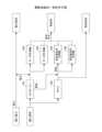
本実施形態に係る運用支援装置10の機能構成を図2に示す。図2に示すように、本実施形態に係る運用支援装置10は、データ取得部201と、需要予測部202と、最適化部203と、シミュレーション部204と、シミュレータ補正部205とを有する。これら各部は、例えば、運用支援装置10にインストールされた1以上のプログラムがプロセッサ105に実行させる処理により実現される。特に、シミュレーション部204は、定常プラントシミュレータとして機能するプログラムがプロセッサ105に実行させる処理により実現される。なお、定常プラントシミュレータとはプラントの定常状態をシミュレーションするためのプログラム又はソフトウェアのことである。 <Functional configuration of the
A functional configuration of the
また、本実施形態に係る運用支援装置10は、運用実績記憶部206を有する。運用実績記憶部206は、例えば、HDDやSSD等の補助記憶装置により実現される。なお、運用実績記憶部206は、例えば、運用支援装置10と通信ネットワークを介して接続される記憶装置(データベースサーバ等)により実現されていてもよい。The
運用実績記憶部206は、プラント20(例えば、需給系統等)の過去の運用実績データを記憶する。ここで、運用実績記憶部206には、過去の時刻s=1,・・・,Sの運用実績データが少なくとも記憶されているものとする。ただし、Sはプラント20の需要予測に用いられる運用実績データ数である。なお、時刻とはプラント20の制御時刻(つまり、制御周期を時間幅に持つ時刻)を表す時刻インデックスのことである。The operation
ここで、例えば、プラント20を構成する各機器をi、時刻sにおける機器iの起動状態をris∈{0,1}、入力値をxis、出力値をyisとすれば、過去の時刻sの運用実績データは{(ris,xis,yis)|i=1,・・・,I}と表される。Iはプラント20を構成する機器の総数である。また、ris=0は機器iが停止していることを表し、ris=1は機器iが起動していることを表す。 Here, for example, if each device constituting the
なお、入力値xis及び出力値yisはスカラーであってもよいし、ベクトルであってもよく、機器iの種類によって異なり得る。例えば、機器iがガスタービンである場合、入力値は燃料を表すスカラー、出力値は電力と蒸気を要素に持つベクトルとなる。一方で、例えば、機器iが冷凍機である場合、入力値は電力を表すスカラー、出力値は熱量(冷熱量)を表すスカラーとなる。 The input value xis and the output value yis may be a scalar or a vector, and may differ depending on the type of device i. For example, if device i is a gas turbine, the input value is a scalar representing fuel, and the output value is a vector having power and steam as elements. On the other hand, if device i is a chiller, the input value is a scalar representing power, and the output value is a scalar representing heat (amount of cold).
また、一般に、ris=0である場合(つまり、機器iが停止している場合)は、xis=0、yis=0であるが、例えば、余熱等によりris=0であってもyis>0であることもあり得る。 Generally, when ris =0 (that is, when device i is stopped), xis =0 and yis =0. However, for example, due to residual heat or the like, even if ris =0, yis >0 may be true.
上記の運用実績記憶部206に記憶される運用実績データは、例えば、プラント20を構成する各機器iの起動状態、入力値、出力値をセンシングする各種センサ等から収集される。The operational performance data stored in the operational
データ取得部201は、プラント20の需要予測(負荷予測)に用いられる過去の運用実績データ{(ris,xis,yis)|i=1,・・・,I,s=1,・・・,S}を運用実績記憶部206から取得する。 The
需要予測部202は、データ取得部201により取得された過去の運用実績データを用いて、将来の時刻t=1,・・・,Tにおけるプラント20全体のエネルギー種別毎の需要(負荷)を予測する。すなわち、エネルギー種別をk、将来の時刻tにおけるエネルギー種別kの需要をLtkとすれば、需要予測部202は、{(Lt1,・・・,LtK)|t=1,・・・,T}を予測する。ここで、Tは予測の最終時刻、Kはエネルギー種別数である。 The
需要予測部202は、既知の手法(例えば、ディープラーニング、ニューラルネットワーク、PLS(Partial Least Squares)回帰等)によりプラント20全体のエネルギー種別毎の需要を予測すればよい。例えば、上記の特許文献1にはニューラルネットワークによりエネルギー種別毎の需要を予測する手法が記載されており、需要予測部202は、この手法によりプラント20全体のエネルギー種別毎の需要を予測すればよい。この他にも、例えば、特開2000-132203号公報、特開2004-171548号公報、特開2015-125593号公報等に記載されている需要(負荷)予測手法によりエネルギー種別毎の需要を予測すればよい。なお、エネルギー種別としては、例えば、電力、熱、蒸気等が挙げられる。The
最適化部203は、需要予測部202により予測された需要を用いて、将来の時刻t=1,・・・,T'におけるプラント20の最適な運用計画を作成する。ここで、T'は、運用計画として作成したい将来の時刻数であり、1≦T'≦Tであれば任意の整数値を設定可能である。The
すなわち、最適化部203は、需要予測部202により予測された需要(エネルギー種別毎の需要予測)の需給バランスとプラント20を構成する各機器の特性とを制約条件、プラント20を構成する各機器iの起動状態と入力値とを状態変数{(rit,xit)|t=1,・・・,T'}として、所定の目的関数を最小化するプラント最適化問題を非線形混合整数計画問題や線形混合整数計画問題等として定式化する。なお、機器の特性としては、例えば、機器の入出力限界(入出力上限)、起動・停止時間等が挙げられる。 That is, the
そして、最適化部203は、上記の状態変数値の初期値を生成した上で、以下の手順1~手順4により最適運用計画を作成し、オペレータ端末30に送信する。なお、状態変数値の初期値はランダムに生成してもよいし、プラント20の運用知識等に基づいてユーザが与えてもよい。Then, the
手順1:状態変数値をシミュレーション部204に入力する。これにより、シミュレーション部204では各機器iの出力値{yit|t=1,・・・,T'}が計算される。 Step 1: State variable values are input to the
手順2:シミュレーション部204で計算された出力値{yit|t=1,・・・,T'}を用いて、目的関数値を計算する。 Step 2: The output values {yit |t=1, . . . , T′} calculated by the
手順3:所定の最適化手法により目的関数値が小さくなるように状態変数値を更新する。Step 3: Update the state variable values using a specified optimization method to reduce the objective function value.
手順4:所定の終了条件を満たすか否かを判定し、当該終了条件を満たさない場合は上記の手順1に戻る。一方で、当該終了条件を満たす場合は現在の状態変数値を{(rit,xit)|t=1,・・・,T'}を最適運用計画とする。なお、現在の状態変数値とそれに対応する出力値{(rit,xit,yit)|t=1,・・・,T'}を最適運用計画としてもよい。 Step 4: Determine whether a predetermined termination condition is satisfied, and if the termination condition is not satisfied, return to step 1 above. On the other hand, if the termination condition is satisfied, the current state variable values {(rit , xit )|t=1, ..., T'} are set as the optimal operation plan. Note that the current state variable values and the corresponding output values {(rit , xit , yit )|t=1, ..., T'} may also be set as the optimal operation plan.
ここで、目的関数値としては、例えば、プラント20全体の運用コスト(エネルギーコスト)、CO2排出量、メンテナンス時間等が挙げられる。最適化手法としては、例えば、非線形混合整数計画問題の場合はBrain Storm Optimization、Modified Brain Storm Optimizaiton、Brain Storm Optimization with Differential Evolution等といったメタヒューリスティクスが挙げれる。一方で、線形混合整数計画問題の場合は線形計画法等が挙げられる。Here, examples of the objective function value include the operating cost (energy cost) of the
また、終了条件としては、例えば、手順1~手順3の繰り返し回数が所定の回数に達したこと、目的関数値が収束したこと、等が挙げられる。In addition, examples of termination conditions include when steps 1 to 3 have been repeated a predetermined number of times, when the objective function value has converged, etc.
なお、上記の手順2で目的関数値の計算に出力値が必要な理由は、例えば、目的関数値としてプラント20全体のエネルギーコストを考えた場合、エネルギー種別kのコストをckとすれば目的関数EはE=Σckと表され、ckは時刻t=1~t=T'までのプラント20全体におけるエネルギー種別kの出力値とその単位コストとの積で表されるためである。 The reason why output values are required to calculate the objective function value in step 2 above is that, for example, when considering the energy cost of the
シミュレーション部204は、最適化部203から状態変数値{(rit,xit,yit)|t=1,・・・,T'}が入力されると、プラント20のシミュレーション(定常状態における運用シミュレーション)を行って、各機器iの出力値{yit|t=1,・・・,T'}を計算する。このとき、シミュレーション部204は、rit=0の場合はyit=0、r=1の場合はyit=fi(xit;αi)により機器iの出力値を計算する。ここで、fiはシミュレーションパラメータαiを持つ関数であり、機器iの出力特性を表す。本実施形態では、簡単のため、一例として、関数fiはfi(x;αi)=αi(aix+bi)という線形関数であるものとする。ai及びbiは機器iの出力特性に応じて決まるパラメータである。ただし、fiが線形関数であることは一例であって、機器iの種類によってはfiが非線形関数であってもよい。 When the state variable values {(rit , xit , yit )|t=1, ..., T'} are input from the
シミュレータ補正部205は、最適運用計画が得られた際にシミュレーション部204で計算された出力値{yit|t=1,・・・,T'}と、当該最適運用計画に基づいてプラント20を実際に運用した際の各機器の出力値との差を用いて、シミュレーションパラメータαiを補正する。例えば、プラント20を実際に運用した際の時刻t=1,・・・,T'における実際の各機器iの出力値をy'itとすれば、シミュレータ補正部205は、各i=1,・・・,Iについて、t=1,・・・,T'に関する|yit-y'it|の和を最小化するようにシミュレーションパラメータαiを補正する。 The
<運用支援装置10が実行する処理>
以下、運用支援装置10が実行する処理として、運用計画作成処理とシミュレータ補正処理について説明する。なお、運用計画作成処理はプラント20の最適運用計画を作成するための処理であり、シミュレータ補正処理は当該最適運用計画とプラント20の実際の運用とに乖離がある場合に定常シミュレータのパラメータを補正するための処理である。 <Processing Executed by
Hereinafter, an operation plan creation process and a simulator correction process will be described as processes executed by the
また、以下では、プラント20として、主に、図3に示す需給系統を想定する。図3に示す需給系統は、燃料を入力して電力と蒸気を出力するガスタービン301と、燃料を入力して蒸気を出力するボイラ302と、電力を入力して熱を出力するターボ冷凍機303及び304と、蒸気を入力して熱を出力する蒸気吸収式冷凍機305及び306とで構成されるエネルギープラントであり、購入電力と購入燃料を入力、電力負荷と熱負荷と蒸気負荷を出力とする。これらの電力負荷、熱負荷、蒸気負荷は各種設備(例えば、生産設備等)で需要される。In the following, the supply and demand system shown in FIG. 3 is mainly assumed as
≪運用計画作成処理≫
本実施形態に係る運用計画作成処理について図4を参照しながら説明する。 <Operation plan creation process>
The operation plan creation process according to this embodiment will be described with reference to FIG.
まず、データ取得部201は、プラント20の需要予測(つまり、図3に示す需給系統の電力負荷、熱負荷、蒸気負荷の予測)に用いられる過去の運用実績データを運用実績記憶部206から取得する(ステップS101)。First, the
次に、需要予測部202は、上記のステップS101で取得された過去の運用実績データを用いて、将来の時刻t=1,・・・,Tにおけるプラント20全体のエネルギー種別毎の需要を予測する(ステップS102)。すなわち、需要予測部202は、{(Lt1,Lt2,Lt3)|t=1,・・・,T}を予測する。ここで、Lt1は時刻tにおける電力負荷の予測値、Lt2は時刻tにおける熱負荷の予測値、Lt3は時刻tにおける蒸気負荷の予測値である。 Next, the
次に、最適化部203は、上記のステップS102で予測された需要を用いて、将来の時刻t=1,・・・,T'におけるプラント20の最適な運用計画を作成する(ステップS103)。Next, the
すなわち、最適化部203は、上記のステップS102で予測された{(Lt1,Lt2,Lt3)|t=1,・・・,T'}と各機器の特性とを制約条件、プラント20を構成する各機器iの起動状態と入力値とを状態変数{(rit,xit)|t=1,・・・,T'}として、所定の目的関数を最小化するプラント最適化問題を非線形混合整数計画問題や線形混合整数計画問題等として定式化する。なお、プラント20を構成する各機器iはそれぞれガスタービン301、ボイラ302、ターボ冷凍機303、ターボ冷凍機304、蒸気吸収式冷凍機305、蒸気吸収式冷凍機306に該当する。 That is, the
そして、最適化部203は、上記の状態変数値の初期値を生成した上で、上記の手順1~手順4により最適運用計画を作成する。なお、上述したように、上記の手順1ではシミュレーション部204により各機器iの出力値{yit|t=1,・・・,T'}が計算される。 Then, the
次に、最適化部203は、上記のステップS103で作成された最適運用計画をオペレータ端末30に送信する(ステップS104)。これにより、オペレータは、各時刻t=1,・・・,T'において、当該最適運用計画を参考にプラント20の運用を制御することができる。Next, the
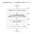
≪シミュレータ補正処理≫
本実施形態に係るシミュレータ補正処理について図5を参照しながら説明する。ここで、以下では、時刻t=1,・・・,T'に関する最適運用計画がオペレータ端末30に送信され、この最適運用計画を参考に各時刻t=1,・・・,T'でプラント20の運用が制御されたものとする。したがって、運用実績記憶部206には、時刻t=1,・・・,T'の運用実績データ{(r'it,x'it,y'it)|i=1,・・・,I,t=1,・・・,T'}が記憶されているものとする。なお、r'itは時刻tにおける機器iの実際の起動状態、x'itは時刻tにおける機器iの実際の入力値、y'itは時刻tにおける機器iの実際の出力値を表す。 <Simulator correction process>
The simulator correction process according to this embodiment will be described with reference to Fig. 5. Here, hereinafter, it is assumed that an optimal operation plan for times t = 1, ..., T' is transmitted to the operator terminal 30, and the operation of the
まず、シミュレータ補正部205は、当該最適運用計画に対応する実際の出力値{y'it|i=1,・・・,I,t=1,・・・,T'}を運用実績記憶部206から取得する(ステップS201)。すなわち、シミュレータ補正部205は、各時刻t=1,・・・,T'において当該最適運用計画を参考にオペレータがプラント20を実際に運用した際の出力値{y'it|i=1,・・・,I,t=1,・・・,T'}を取得する。
次に、シミュレータ補正部205は、当該最適運用計画が得られた際にシミュレーション部204で計算された出力値{yit|t=1,・・・,T'}と、上記のステップS201で取得した出力値{y'it|i=1,・・・,I,t=1,・・・,T'}との差を用いて、この際を最小化するシミュレーションパラメータα'iを算出する(ステップS202)。すなわち、シミュレータ補正部205は、各i=1,・・・,Iについて、|yi1-y'i1|+・・・+|yiT'-y'iT'|を最小化するシミュレーションパラメータα'iを算出する。これは、|yi1-y'i1|+・・・+|yiT'-y'iT'|を目的関数として既知の最適化手法により算出することが可能である。 First, the
Next, the
次に、シミュレータ補正部205は、各i=1,・・・,Iについて、上記のステップS202で算出したシミュレーションパラメータα'iを定常プラントシミュレータに反映するか否かを判定する(ステップS203)。シミュレータ補正部205は、例えば、|αi-α'i|が所定の閾値よりも大きい場合はシミュレーションパラメータα'iを定常プラントシミュレータに反映すると判定し、一方で|αi-α'i|が当該閾値以下である場合はシミュレーションパラメータα'iを定常プラントシミュレータに反映しないと判定する。なお、αiは機器iに関する現在のシミュレーションパラメータである。 Next, the
そして、シミュレータ補正部205は、上記のステップS203で定常プラントシミュレータに反映すると判定されたシミュレーションパラメータα'iについて、定常プラントシミュレータに反映する(ステップS204)。すなわち、シミュレータ補正部205は、αi←α'iとシミュレーションパラメータαiを更新する。これにより、シミュレーションパラメータαiが補正される。 Then, the
以上のように、本実施形態に係る運用支援装置10は、オペレータによる実際の運用との差を用いてシミュレーションパラメータαiを補正するため、例えば、プラント20を構成する機器の経年劣化等に伴う特性変化も考慮した最適な運用計画を作成することが可能となる。 As described above, the
<変形例>
以下、本実施形態の変形例について説明する。 <Modification>
A modification of this embodiment will now be described.
≪変形例1≫
図4のステップS204では最適運用計画をオペレータ端末30に送信したが、例えば、定常プラントシミュレータがオペレータの実際の運用を精度良くシミュレーションしている場合には、最適運用計画に従って運用支援装置10がプラント20の運用を制御してもよい。なお、定常プラントシミュレータがオペレータの実際の運用を精度良くシミュレーションしている場合とは、例えば、直近の最適運用計画において、全てのiについて(又は、所定の個数若しくは所定の比率以上のiについて)、図5のステップS203で|αi-α'i|が所定の閾値以下である場合等が挙げられえる。 <Modification 1>
In step S204 in Fig. 4, the optimal operation plan was transmitted to the operator terminal 30, but for example, when the steady-state plant simulator accurately simulates the actual operation of the operator, the
≪変形例2≫
図5のステップS204ではシミュレーションパラメータαiをαi←α'iと更新したが、例えば、重み付け和で更新してもよい。例えば、0<γi<1を予め決められたパラメータとして、αi←γiαi+(1-γi)α'iと更新してもよい。また、このとき、γiはすべてのiに対して同一であってもよいし、異なっていてもよい。この変形例2を用いることで、現在のシミュレーションパラメータの値も考慮した上でその補正を行うことができるようになる。 <<Modification 2>>
In step S204 of Fig. 5, the simulation parameterαi is updated asαi ←α'i , but it may be updated by a weighted sum, for example. For example, it may be updated asαi ←γiαi +(1-γi )α'i , with0 <γi <1 as a predetermined parameter. In this case,γi may be the same for all i, or may be different. By using this modification 2, it becomes possible to perform the correction while taking into consideration the current simulation parameter value.
本発明は、具体的に開示された上記の実施形態に限定されるものではなく、特許請求の範囲の記載から逸脱することなく、種々の変形や変更、既知の技術との組み合わせ等が可能である。The present invention is not limited to the specifically disclosed embodiments above, and various modifications, changes, and combinations with known technologies are possible without departing from the scope of the claims.
10 運用支援装置
20 プラント
30 オペレータ端末
101 入力装置
102 表示装置
103 外部I/F
103a 記録媒体
104 通信I/F
105 プロセッサ
106 メモリ装置
107 バス
201 データ取得部
202 需要予測部
203 最適化部
204 シミュレーション部
205 シミュレータ補正部
206 運用実績記憶部 REFERENCE SIGNS
103a Recording medium 104 Communication I/F
105
Claims (8)
Translated fromJapanese前記プラントを構成する各機器の起動状態と入力値と出力値とが含まれる運用実績データを用いて、前記プラントの将来の需要を予測する予測部と、
前記プラントの運用をシミュレーションするシミュレータを用いて、前記需要と前記プラントを構成する各機器の特性とを制約条件として所定の目的関数を最適化することで、前記プラントを構成する各機器の将来の起動状態及び入力値の計画を少なくとも表す前記運用計画を作成する最適化部と、
前記運用計画を作成したときに前記シミュレータで計算された出力値と、前記プラントを実際に運用したときの出力値との差を用いて、前記シミュレータのパラメータを補正する補正部と、
を有する運用支援装置。 An operation support device that creates a plant operation plan,
a prediction unit that predicts future demand for the plant using operation performance data including the start-up state, input values, and output values of each device that constitutes the plant;
an optimization unit that creates the operation plan, which represents at least a plan of a future start-up state and an input value of each device that configures the plant, by optimizing a predetermined objective function using a simulator that simulates the operation of the plant and setting the demand and characteristics of each device that configures the plant as constraint conditions;
a correction unit that corrects parameters of the simulator using a difference between an output value calculated by the simulator when the operation plan is created and an output value when the plant is actually operated;
An operational support device having the above configuration.
将来の時刻t=1,・・・,Tにおける前記需要を予測し、
前記最適化部は、
将来の時刻t=1,・・・,T'(ただし、1≦T'≦T)における各機器iの起動状態ritと入力値xitとが含まれる前記運用計画を作成し、
前記補正部は、
前記運用計画に含まれる起動状態ritと入力値xitとを前記シミュレータに入力することで計算された出力値yitと、時刻tにおいて前記プラントを実際に運用したときの機器iの出力値y'itとの差を用いて、前記差を最小化するように、前記パラメータを補正する、請求項1に記載の運用支援装置。 The prediction unit is
forecasting the demand at future times t=1, ..., T;
The optimization unit is
The operation plan is created, which includes the start-up state rit and the input value xit of each device i at future times t = 1, ..., T' (where 1 ≤ T' ≤ T),
The correction unit is
2. The operation support device according to claim 1, wherein the parameters are corrected so as to minimize a difference between an output value yit calculated by inputting a start-up state rit and an input value xit included in the operation plan to the simulator, and an output value y'it of an equipment i when the plant is actually operated at time t.
前記シミュレータは、
前記起動状態ritが、前記機器iが起動していないことを表す値である場合は、yit=0と計算し、
前記起動状態ritが、前記機器iが起動していることを表す値である場合は、前記パラメータαiを持つ関数fiによりyit=fi(xit;αi)と計算する、請求項2に記載の運用支援装置。 The parameter for device i is defined as αi ,
The simulator comprises:
If the activation state rit is a value indicating that the device i is not activated, yit =0 is calculated;
3. The operation support device according to claim 2, wherein when the activation state rit is a value indicating that the device i is activated, calculation is performed as yit =fi (xit ; αi ) using a function fi having the parameter αi .
前記差を最小化する前記パラメータの値α'iを計算し、|αi-α'i|が所定の閾値よりも大きい場合は、α'iを用いて、前記パラメータαiを更新する、請求項3に記載の運用支援装置。 The correction unit is
4. The operation support device according to claim 3, further comprising: calculating a valueα'i of the parameter that minimizes the difference; and updating the parameterαi usingα'i when |αi -α'i | is greater than a predetermined threshold value.
αi←α'iにより前記パラメータαiを更新する、請求項4に記載の運用支援装置。 The correction unit is
5. The operation support device according to claim 4, wherein the parameter αi is updated by αi ←α'i .
αi←γiαi+(1-γi)α'i(ただし、0<γi<1)により前記パラメータαiを更新する、請求項4に記載の運用支援装置。 The correction unit is
5. The operation support device according to claim 4, wherein the parameterαi is updated byαi ←γiαi +(1-γi )α'i (where 0<γi <1).
前記プラントを構成する各機器の起動状態と入力値と出力値とが含まれる運用実績データを用いて、前記プラントの将来の需要を予測する予測手順と、
前記プラントの運用をシミュレーションするシミュレータを用いて、前記需要と前記プラントを構成する各機器の特性とを制約条件として所定の目的関数を最適化することで、前記プラントを構成する各機器の将来の起動状態及び入力値の計画を少なくとも表す前記運用計画を作成する最適化手順と、
前記運用計画を作成したときに前記シミュレータで計算された出力値と、前記プラントを実際に運用したときの出力値との差を用いて、前記シミュレータのパラメータを補正する補正手順と、
をコンピュータが実行する運用支援方法。 An operation support device that creates a plant operation plan,
a prediction step of predicting future demand for the plant using operation result data including the start-up state, input values, and output values of each device constituting the plant;
an optimization procedure for creating the operation plan, which represents at least a plan of a future start-up state and an input value of each device constituting the plant, by optimizing a predetermined objective function using a simulator that simulates the operation of the plant and setting the demand and characteristics of each device constituting the plant as constraint conditions;
a correction step of correcting parameters of the simulator using a difference between an output value calculated by the simulator when the operation plan is created and an output value when the plant is actually operated;
The operational support method is carried out by a computer.
前記プラントを構成する各機器の起動状態と入力値と出力値とが含まれる運用実績データを用いて、前記プラントの将来の需要を予測する予測手順と、
前記プラントの運用をシミュレーションするシミュレータを用いて、前記需要と前記プラントを構成する各機器の特性とを制約条件として所定の目的関数を最適化することで、前記プラントを構成する各機器の将来の起動状態及び入力値の計画を少なくとも表す前記運用計画を作成する最適化手順と、
前記運用計画を作成したときに前記シミュレータで計算された出力値と、前記プラントを実際に運用したときの出力値との差を用いて、前記シミュレータのパラメータを補正する補正手順と、
をコンピュータに実行させるプログラム。 The operation support device that creates the plant operation plan
a prediction step of predicting future demand for the plant using operation result data including the start-up state, input values, and output values of each device constituting the plant;
an optimization procedure for creating the operation plan, which represents at least a plan of a future start-up state and an input value of each device constituting the plant, by optimizing a predetermined objective function using a simulator that simulates the operation of the plant and setting the demand and characteristics of each device constituting the plant as constraint conditions;
a correction step of correcting parameters of the simulator using a difference between an output value calculated by the simulator when the operation plan is created and an output value when the plant is actually operated;
A program that causes a computer to execute the following.
Priority Applications (1)
| Application Number | Priority Date | Filing Date | Title |
|---|---|---|---|
| JP2021101065AJP7647372B2 (en) | 2021-06-17 | 2021-06-17 | Operation support device, operation support method, and program |
Applications Claiming Priority (1)
| Application Number | Priority Date | Filing Date | Title |
|---|---|---|---|
| JP2021101065AJP7647372B2 (en) | 2021-06-17 | 2021-06-17 | Operation support device, operation support method, and program |
Publications (2)
| Publication Number | Publication Date |
|---|---|
| JP2023000319A JP2023000319A (en) | 2023-01-04 |
| JP7647372B2true JP7647372B2 (en) | 2025-03-18 |
Family
ID=84687816
Family Applications (1)
| Application Number | Title | Priority Date | Filing Date |
|---|---|---|---|
| JP2021101065AActiveJP7647372B2 (en) | 2021-06-17 | 2021-06-17 | Operation support device, operation support method, and program |
Country Status (1)
| Country | Link |
|---|---|
| JP (1) | JP7647372B2 (en) |
Citations (7)
| Publication number | Priority date | Publication date | Assignee | Title |
|---|---|---|---|---|
| JP2002006938A (en) | 2000-06-22 | 2002-01-11 | Hitachi Ltd | Operation management system and maintenance management service method for power generation equipment |
| JP2006048474A (en) | 2004-08-06 | 2006-02-16 | Fuji Electric Systems Co Ltd | Plant optimum operation planning device |
| WO2012105231A1 (en) | 2011-02-03 | 2012-08-09 | 日本電気株式会社 | Model adaptation device, model adaptation method, and program for model adaptation |
| WO2013161793A1 (en) | 2012-04-24 | 2013-10-31 | 日本電気株式会社 | Wireless parameter control device, wireless base station, wireless parameter control method, and program |
| JP2015510079A (en) | 2012-03-01 | 2015-04-02 | ヌオーヴォ ピニォーネ ソチエタ レスポンサビリタ リミタータNuovo Pignone S.R.L. | Method and system for real-time gas turbine performance notification |
| JP2019040483A (en) | 2017-08-28 | 2019-03-14 | 三菱電機株式会社 | Electricity transaction development device |
| JP2019057035A (en) | 2017-09-20 | 2019-04-11 | 株式会社東芝 | Operation plan creating device, control device, operation plan creating method and operation plan creating program |
- 2021
- 2021-06-17JPJP2021101065Apatent/JP7647372B2/enactiveActive
Patent Citations (7)
| Publication number | Priority date | Publication date | Assignee | Title |
|---|---|---|---|---|
| JP2002006938A (en) | 2000-06-22 | 2002-01-11 | Hitachi Ltd | Operation management system and maintenance management service method for power generation equipment |
| JP2006048474A (en) | 2004-08-06 | 2006-02-16 | Fuji Electric Systems Co Ltd | Plant optimum operation planning device |
| WO2012105231A1 (en) | 2011-02-03 | 2012-08-09 | 日本電気株式会社 | Model adaptation device, model adaptation method, and program for model adaptation |
| JP2015510079A (en) | 2012-03-01 | 2015-04-02 | ヌオーヴォ ピニォーネ ソチエタ レスポンサビリタ リミタータNuovo Pignone S.R.L. | Method and system for real-time gas turbine performance notification |
| WO2013161793A1 (en) | 2012-04-24 | 2013-10-31 | 日本電気株式会社 | Wireless parameter control device, wireless base station, wireless parameter control method, and program |
| JP2019040483A (en) | 2017-08-28 | 2019-03-14 | 三菱電機株式会社 | Electricity transaction development device |
| JP2019057035A (en) | 2017-09-20 | 2019-04-11 | 株式会社東芝 | Operation plan creating device, control device, operation plan creating method and operation plan creating program |
Also Published As
| Publication number | Publication date |
|---|---|
| JP2023000319A (en) | 2023-01-04 |
Similar Documents
| Publication | Publication Date | Title |
|---|---|---|
| CN104049538B (en) | Method and apparatus for compensating the simulation model based on First Principle | |
| US11573541B2 (en) | Future state estimation device and future state estimation method | |
| US7219040B2 (en) | Method and system for model based control of heavy duty gas turbine | |
| US8874242B2 (en) | Graphical language for optimization and use | |
| JP2020095352A (en) | Control device, control method and program | |
| EP3913452A1 (en) | Operating index presenting device, operating index presenting method, and program | |
| US20120239169A1 (en) | Transparent models for large scale optimization and control | |
| JP2013109711A (en) | Plant model creation device and plant operation support system | |
| JP7700730B2 (en) | Model selection device, model selection method, and model selection program | |
| Khokhlovskiy et al. | Development of control automation for energy objects based on the unified process approach | |
| US20230061033A1 (en) | Information processing device, calculation method, and computer-readable recording medium | |
| Gordon et al. | Data-driven and safety-aware holistic production planning | |
| JP7060130B1 (en) | Operation support equipment, operation support methods and programs | |
| JP7647372B2 (en) | Operation support device, operation support method, and program | |
| Pilarski et al. | Predictions-on-chip: model-based training and automated deployment of machine learning models at runtime: For multi-disciplinary design and operation of gas turbines | |
| US12292730B2 (en) | Information processing device, evaluation method, and computer-readable recording medium | |
| US20250005409A1 (en) | Future state estimation apparatus | |
| Wang et al. | Time dependent supervisory control update with FARM using rolling window | |
| Serralunga et al. | Including disjunctions in real-time optimization | |
| Ehlhardt et al. | Real‐Time Optimization Using Machine Learning Models Applied to the 4, 4′‐Diphenylmethane Diisocyanate Production Process | |
| Orka et al. | Artificial intelligence-based online control scheme for the regulations of interconnected thermal power systems | |
| Aissat et al. | Identification of twin-shaft gas turbine based on hybrid decoupled state multiple model approach | |
| Krcala et al. | Control Logic Encoding using RiskSpectrum ModelBuilder | |
| JP2003500717A (en) | Method, apparatus and computer program for designing a technical system | |
| JP7410083B2 (en) | Start-up control device, start-up control method, and start-up control program |
Legal Events
| Date | Code | Title | Description |
|---|---|---|---|
| A621 | Written request for application examination | Free format text:JAPANESE INTERMEDIATE CODE: A621 Effective date:20240514 | |
| A977 | Report on retrieval | Free format text:JAPANESE INTERMEDIATE CODE: A971007 Effective date:20250123 | |
| TRDD | Decision of grant or rejection written | ||
| A01 | Written decision to grant a patent or to grant a registration (utility model) | Free format text:JAPANESE INTERMEDIATE CODE: A01 Effective date:20250204 | |
| A61 | First payment of annual fees (during grant procedure) | Free format text:JAPANESE INTERMEDIATE CODE: A61 Effective date:20250217 | |
| R150 | Certificate of patent or registration of utility model | Ref document number:7647372 Country of ref document:JP Free format text:JAPANESE INTERMEDIATE CODE: R150 |