JP7647049B2 - Electronic device, imaging device, display method and program - Google Patents
Electronic device, imaging device, display method and programDownload PDFInfo
- Publication number
- JP7647049B2 JP7647049B2JP2020167765AJP2020167765AJP7647049B2JP 7647049 B2JP7647049 B2JP 7647049B2JP 2020167765 AJP2020167765 AJP 2020167765AJP 2020167765 AJP2020167765 AJP 2020167765AJP 7647049 B2JP7647049 B2JP 7647049B2
- Authority
- JP
- Japan
- Prior art keywords
- image
- display
- displayed
- function
- display unit
- Prior art date
- Legal status (The legal status is an assumption and is not a legal conclusion. Google has not performed a legal analysis and makes no representation as to the accuracy of the status listed.)
- Active
Links
Images


Landscapes
- Camera Bodies And Camera Details Or Accessories (AREA)
- Indication In Cameras, And Counting Of Exposures (AREA)
- Studio Devices (AREA)
- User Interface Of Digital Computer (AREA)
Description
Translated fromJapanese本発明は、電子機器、撮像装置、表示方法およびプログラムに関する。The present invention relates to an electronic device, an imaging device, a display method, and a program.
従来、表示中の画像に対応する機能に関連する機能を実現させるために、ユーザの操作に応じて、表示中の画像とは異なる画像を表示する電子機器が開発されている。例えば、特許文献1には、アプリケーションプログラムに規定された処理を実行する携帯電子デバイスが開示されている。この携帯電子デバイスは、ユーザの操作に応答して、ホーム画面を含む第一の画面表示レイアウトから、当該プログラムの使用可能な設定メニューに対応するアイコンを含む第二の画面表示レイアウトに、表示画面を遷移させる。Conventionally, electronic devices have been developed that display an image different from the currently displayed image in response to a user's operation in order to realize a function related to a function corresponding to the currently displayed image. For example,
特許文献1には、第一の画面表示レイアウトを表示させたまま、第二の画面表示レイアウトを表示させるという技術思想は開示されていない。特許文献1に記載の技術では、第二の画面表示レイアウトが表示されると、第一の画面表示レイアウトで選択できた機能が選択できなくなり、操作性という観点で改善の余地がある。
開示の技術は、操作性が良い電子機器を提供することを目的とする。The disclosed technology aims to provide electronic devices that are easy to use.
開示の技術は、表示部を有する電子機器であって、当該電子機器における第一機能に対応する第一画像が前記表示部に表示されている状態において、前記第一機能とは異なり、前記第一画像に関する設定を行う第二機能に対応する第二画像を表示させる操作を受け付けると、前記第一画像の少なくとも一部を表示させたまま、前記第二画像を前記表示部に表示させる制御部を備え、前記制御部は、前記表示部に前記第一画像および前記第二画像が表示されている場合に、前記第一機能および前記第二機能とは異なり、前記電子機器に関する設定を行う第三機能に対応する第三画像を表示させる操作を受け付けると、前記第一画像および前記第二画像を前記表示部に表示される表示画面から消去して、前記第三画像を前記表示部に表示させ、前記第二機能および前記第三機能は、撮影に関する設定を受け付ける機能であり、前記第三画像において表示される機能の数は、前記第二画像において表示される機能の数よりも多い、電子機器である。
The disclosed technology is an electronic device having a display unit, which, when a first image corresponding to a first function of the electronic device is displayed on the display unit, and when an operation to display a second image corresponding to a second function different from the first function and which makes settings related to the first image is accepted, a control unit causes the second image to be displayed on the display unit while keeping at least a portion of the first image displayed, and when the control unit accepts an operation to display a third image corresponding to a third function different from the first function and the second function and which makes settings related to the electronic device while the first image and the second image are displayed on the display unit, the control unit erases the first image and the second image from the display screen displayed on the display unit and displays the third image on the display unit, the second function and the third function are functions that accept settings related to photography, and the number of functions displayed in the third image is greater than the number of functions displayed in the second image .
開示の技術によると、操作性が良い電子機器を実現することができる。The disclosed technology makes it possible to realize electronic devices with good operability.
以下に、図面を参照して本発明に係る電子機器の一例である撮像装置の実施の形態について説明する。電子機器は撮像装置に限らず、スマートフォン、タブレット端末、ゲーム機、PDA(Personal Digital Assistant)、ウェアラブルPC等であってもよい。Below, an embodiment of an imaging device, which is an example of an electronic device according to the present invention, will be described with reference to the drawings. The electronic device is not limited to an imaging device, but may be a smartphone, a tablet terminal, a game console, a PDA (Personal Digital Assistant), a wearable PC, etc.
図1は、撮像装置のハードウェア構成の一例を示す図である。Figure 1 shows an example of the hardware configuration of an imaging device.
撮像装置1は、撮像ユニット101と、画像処理ユニット104と、撮像制御ユニット105と、マイク108と、音処理ユニット109と、CPU(Central Processing Unit)111と、ROM(Read Only Memory)112と、SRAM(Static Random Access Memory)113と、DRAM(Dynamic Random Access Memory)114と、操作部115と、外部機器接続I/F116と、通信部117と、アンテナ117aと、加速度・方位センサ118と、タッチパネル119と、を備える。The
このうち、撮像ユニット101は、広角レンズ102aおよび広角レンズ102bと、各広角レンズに対応させて設けられている2つの撮像素子103aおよび撮像素子103bと、を備える。広角レンズ102aおよび広角レンズ102bは、いわゆる魚眼レンズであって、各々半球画像を結像するための180°以上の画角を有する。Of these, the
撮像素子103aおよび撮像素子103bは、それぞれ広角レンズ102aまたは広角レンズ102bによる光学像を電気信号の画像データに変換して出力するCMOS(Complementary Metal Oxide Semiconductor)センサやCCD(Charge Coupled Device)センサなどの画像センサ、画像センサの水平又は垂直同期信号や画素クロックなどを生成するタイミング生成回路、撮像素子の動作に必要な種々のコマンド、パラメータなどが設定されるレジスタ群などを有している。The
撮像ユニット101の撮像素子103aおよび撮像素子103bは、各々、画像処理ユニット104と、シリアルI/Fバスを介して接続されている。また、撮像ユニット101の撮像素子103aおよび103bは、各々、撮像制御ユニット105と、シリアルI/Fバス(I2Cバス等)を介して接続されている。The
画像処理ユニット104、撮像制御ユニット105及び音処理ユニット109は、バス110を介してCPU111と接続されている。さらに、バス110には、ROM112、SRAM113、DRAM114、操作部115、外部機器接続I/F(Interface)116、通信部117、加速度・方位センサ118、タッチパネル119などが接続されている。The
画像処理ユニット104は、撮像素子103aおよび撮像素子103bから出力される画像データをシリアルI/Fバスを通して取り込み、それぞれの画像データに対して所定の処理を施した後、これらの画像データを合成して、正距円筒射影画像のデータを作成する。The
撮像制御ユニット105は、一般に撮像制御ユニット105をマスタデバイス、撮像素子103aおよび撮像素子103bをスレーブデバイスとして、I2Cバスを利用して、撮像素子103aおよび撮像素子103bのレジスタ群にコマンド等を設定する。撮像制御ユニット105は、必要なコマンド等をCPU111から受け取る。また、撮像制御ユニット105は、同じくI2Cバスを利用して、撮像素子103aおよび撮像素子103bのレジスタ群のステータスデータ等を取り込み、CPU111に送る。The
また、撮像制御ユニット105は、操作部115のシャッターボタンが押下されたタイミングで、撮像素子103aおよび撮像素子103bに画像データの出力を指示する。撮像装置1は、タッチパネル119または外部装置に撮像装置1が撮影した動画像を表示するライブビュー表示機能を有する。そのため、撮像素子103aおよび撮像素子103bは、画像データの出力を所定のフレームレート(フレーム/分)によって連続して行う。In addition, the
また、撮像制御ユニット105は、後述するように、CPU111と協働して撮像素子103aおよび撮像素子103bの画像データの出力タイミングの同期をとる同期制御手段としても機能する。The
マイク108は、音を音(信号)データに変換する。音処理ユニット109は、マイク108から出力される音データをI/Fバスを通して取り込み、音データに対して所定の処理を施す。The
CPU111は、撮像装置1の全体の動作を制御すると共に必要な処理を実行する。ROM112は、CPU111のための種々のプログラムを記憶している。SRAM113及びDRAM114はワークメモリであり、CPU111で実行するプログラムや処理途中のデータ等を記憶する。なお、DRAM114は、画像処理ユニット104での処理途中の画像データや処理済みの正距円筒射影画像のデータを記憶する。The
操作部115は、シャッターボタンなどの操作ボタンを有する。ユーザは操作部115を操作することで、種々の撮影モードや撮影条件などを入力する。The
外部機器接続I/F116は、各種の外部機器を接続するためのインターフェースである。この場合の外部機器は、例えば、USB(Universal Serial Bus)メモリ、PC(Personal Computer)等である。撮像装置1は、DRAM114に記憶された正距円筒射影画像のデータを、この外部機器接続I/F116を介して外付けのメディアに記録する。また、撮像装置1は、外部機器接続I/F116を介してスマートフォン等の外部端末(装置)に送信しても良い。The external device connection I/
通信部117は、撮像装置1に設けられたアンテナ117aを介して、Wi-Fi、NFC(Near Field Communication)、Bluetooth(登録商標)等の近距離無線通信技術によって、スマートフォン等の外部端末(装置)と通信を行う。この通信部117によっても、正距円筒射影画像のデータをスマートフォン等の外部端末(装置)に送信することができる。The
加速度・方位センサ118は、地球の磁気から撮像装置1の方位を算出し、方位情報を出力する。この方位情報はExifに沿った関連情報(メタデータ)の一例であり、撮影画像の画像補正等の画像処理に利用される。なお、関連情報には、画像の撮影日時、及び画像データのデータ容量の各データも含まれている。また、加速度・方位センサ118は、撮像装置1の移動に伴う角度の変化(Roll角、Pitch角、Yaw角)を検出する。The acceleration and
角度の変化はExifに沿った関連情報(メタデータ)の一例であり、撮像画像の画像補正等の画像処理に利用される。更に、加速度・方位センサ118は、3軸方向の加速度を検出する。撮像装置1は、加速度・方位センサ118が検出した加速度に基づいて、自装置(撮像装置1)の姿勢(重力方向に対する角度)を算出する。撮像装置1に、加速度・方位センサ118が設けられることによって、画像補正の精度が向上する。The change in angle is an example of related information (metadata) according to Exif, and is used in image processing such as image correction of the captured image. Furthermore, the acceleration/
タッチパネル119は、表示部119aと、位置入力部119bと、を備える。表示部119aには、例えば液晶ディスプレイ等であって、撮像ユニット101から送信される撮像画像、ROM112に格納されたアイコン画像などを含む表示画面が表示される。The
位置入力部119bは、表示部119aへの接触を検知し、接触された位置を示す位置情報をCPU111に出力する。The position input unit 119b detects contact with the
なお、撮像装置1は、ソフトシャッター機能を有する。ソフトシャッター機能とは、タッチパネル119に表示されたシャッター領域への接触を検知した場合に、画像を撮影する機能である。すなわち、撮像装置1は、シャッター領域への接触を検知した場合に、操作部115のシャッターボタンが押下された場合と同様に、シャッターを切る処理を実行する。The
図1に示した撮像装置1は、2つの撮像素子を使用した全天球撮影装置であるが、撮像素子は2つに限定するものでなく、いくつでもよい。また、撮像装置1は、全天球撮影装置である必要はなく、画像を撮影する装置であればよい。また、撮像装置1は、後付けの全方位の撮像ユニットを取り付けられたデジタルカメラ、スマートフォン等であっても良い。The
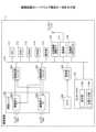
図2は、撮像装置の機能の一例を示す図である。Figure 2 shows an example of the functions of an imaging device.
撮像装置1は、制御部10を備える。制御部10は、CPU111が、ROM112、SRAM113またはDRAM114等に記憶されたプログラムに規定された処理を実行することによって、実現される。The
制御部10は、第一表示制御部13と、第一操作受付部14と、第二表示制御部15と、第二操作受付部16と、第三表示制御部17と、撮像操作受付部18と、を含む。The
第一表示制御部13は、第一機能に対応する第一画像を表示部119aに表示させる。第一機能は、自機(撮像装置1)が実現する機能であって、例えば、ライブビュー表示機能またはソフトシャッター機能である。その場合、第一画像は、ライブビュー表示機能を実現するための動画像またはソフトシャッター機能に対応するシャッター領域を示す画像である。The first
第一操作受付部14は、表示部119aに第一画像が表示されている場合に、第一機能とは異なる第二機能に対応する第二画像を表示させる操作を受け付ける。具体的には、第二機能は、第一機能に関連する機能であり、例えば、ライブビュー表示機能における動画像の表示に関する設定、またはソフトシャッター機能における静止画像の撮影に関する設定を受け付ける機能である。例えば、第二機能は、露出、ホワイトバランス、シャッタースピード等の設定を受ける機能である。When a first image is displayed on the
第二画像を表示させる操作は、例えば、表示部119aにおける表示領域の端部から中央に向けられたスワイプ操作である。The operation for displaying the second image is, for example, a swipe operation from the edge of the display area on the
また、第一操作受付部14は、表示部119aに第一画像と第二画像が表示されている場合は、第二画像を消去する操作を受け付ける。第二画像を消去する操作は、例えば、表示部119aにおける表示領域の中央から端部に向けられたスワイプ操作である。この場合の端部は、表示中の第二画像を表示させるスワイプ操作において接触が検知された端部である。When the first image and the second image are displayed on the
第二表示制御部15は、第一操作受付部14が第二画像を表示させる操作を受け付けると、第一画像を表示させたまま、第二画像を表示部119aに表示させる。具体的には、第二表示制御部15は、少なくとも第一画像の一部と第二画像とを含む表示画面を表示部119aに表示させる。これによって、撮像装置1のユーザは、ライブビュー表示機能による動画像を見ながら露出、ホワイトバランス、シャッタースピード等の設定が可能となったり、ソフトシャッター機能を利用してシャッターを切ったりすることができる。When the first
また、第二表示制御部15は、第一操作受付部14が第二画像を消去する操作を受け付けると、第二画像を表示画面から消去する。これによって、第二表示制御部15は、第二画像によって隠れていた部分に相当する第一画像を表示部119aに表示させる。When the first
第二操作受付部16は、表示部119aに第一画像および第二画像が表示されている場合に、第一機能および第二機能とは異なる第三機能に対応する第三画像を表示させる操作を受け付ける。具体的には、第三画像は、第二画像に対応する設定とは異なる設定に対応する画像である。例えば、第三画像は、撮像装置1についての詳細な設定に対応する画像である。When the first image and the second image are displayed on the
第三画像を表示させる操作は、第二画像を表示させる操作と同様に、例えば、表示部119aにおける表示領域の端部から中央に向けられたスワイプ操作である。第三画像を表示させる操作が、第二画像を表示させる操作と同様であれば、撮像装置1のユーザは、操作方法を複数記憶する必要が無いため、操作性が良い。The operation to display the third image is, for example, a swipe operation from the edge to the center of the display area on the
なお、この場合、第二画像を表示させる操作と第三画像を表示させる操作との違いは、表示部119aに第一画像が表示されている場合に受け付けた操作であるか、表示部119aに第一画像および第二画像が表示されている場合に受け付けた操作であるかの違いである。In this case, the difference between the operation to display the second image and the operation to display the third image is whether the operation is accepted when the first image is displayed on the
また、第二操作受付部16は、表示部119aに第三画像が表示されている場合は、第三画像を消去する操作を受け付ける。第三画像を消去する操作は、例えば、表示部119aにおける表示領域の中央から端部に向けられたスワイプ操作である。この場合の端部は、表示中の第三画像を表示させるスワイプ操作において接触が検知された端部である。When the third image is displayed on the
第三表示制御部17は、第二操作受付部16が第三画像を表示させる操作を受け付けると、第一画像および第二画像を表示画面から消去して、第三画像を表示部119aに表示させる。これによって、撮像装置1のユーザは、表示部119aの表示領域における広い範囲を利用して詳細な設定を行うことができる。When the second
また、第三表示制御部17は、第二操作受付部16が第三画像を消去する操作を受け付けると、第三画像を表示画面から消去する。これによって、第三表示制御部17は、第三画像によって隠れていた部分に相当する第一画像および第二画像を表示部119aに表示させる。When the second
第一表示制御部13、第一操作受付部14、第二表示制御部15、第二操作受付部16および第三表示制御部17は、CPU111によって実現される。The first
撮像操作受付部18は、撮像操作を受け付ける。具体的には、撮像操作受付部18は、操作部115が有するシャッターボタンの押下を検知するか、またはソフトシャッター機能のシャッター領域への接触を検知することによって、撮像操作を受け付ける。The imaging
次に、表示部119aに表示される画像について説明する。Next, we will explain the images displayed on the
図3は、第一画像の一例を示す図である。Figure 3 shows an example of the first image.
図3は、表示部119aに表示される表示画面900に、第一画像が含まれる例を示している。第一画像は、撮像された動画像と、シャッター領域を示すアイコン画像901と、を含む。撮像操作受付部18は、アイコン画像901に囲まれた領域への接触を検知すると、撮像操作として受け付ける。Figure 3 shows an example in which a first image is included on the display screen 900 displayed on the
図4は、第二画像の表示方法について説明するための第一の図である。Figure 4 is the first diagram for explaining the method of displaying the second image.
第一操作受付部14がスワイプ操作等の操作を受け付けると、第二表示制御部15は、その操作に応じたアニメーション動作によって、第二画像902を表示部119aに表示させる。具体的には、第二表示制御部15は、第一操作受付部14が表示部119aにおける表示領域の下端から中央に向けられたスワイプ操作を受け付けると、図4に示すように、表示部119aにおける表示領域の下端から中央に向けて徐々に表示範囲を拡大しながら第二画像902を表示部119aに表示させる。When the first
図5は、第二画像の表示方法について説明するための第二の図である。Figure 5 is a second diagram illustrating a method for displaying a second image.
第二表示制御部15は、第二画像902の表示範囲が最も拡大された状態でも、図5に示すように、ライブビュー表示機能による動画像の主要な部分と、アイコン画像901とが表示されたまま、第二画像902を表示部119aに表示させる。したがって、図5に示す状態では、ライブビュー表示機能およびソフトシャッター機能は有効なまま維持されている。Even when the display range of the second image 902 is maximized, the second
なお、図5に示す第二画像902は、露出設定、ホワイトバランス設定およびシャッタースピード設定を受け付ける機能に対応する画像である。Note that the second image 902 shown in FIG. 5 is an image corresponding to a function that accepts exposure settings, white balance settings, and shutter speed settings.
図6は、スワイプ操作について説明するための図である。Figure 6 is a diagram explaining the swipe operation.
図6に示されるマス目は、表示部119aの表示領域を複数の小領域に区切ったものである。位置入力部119bは、各小領域への接触を検知する。具体的には、各小領域は、表示部119aの表示領域の上端部801、下端部802、左端部803、右端部804および中央部805のいずれかに区分されている。The grid shown in FIG. 6 divides the display area of the
第一操作受付部14または第二操作受付部16は、上端部801、下端部802、左端部803または右端部804のいずれかへの接触を検知し、接触されたまま接触の位置が中央部805に向かって移動することを検知すると、第二画像または第三画像を表示させる操作として受け付ける。The first
図7は、第三画像の表示方法について説明するための第一の図である。Figure 7 is the first diagram for explaining the display method of the third image.
第二操作受付部16がスワイプ操作等の操作を受け付けると、第三表示制御部17は、その操作に応じたアニメーション動作によって、第三画像903を表示部119aに表示させる。具体的には、第三表示制御部17は、第二操作受付部16が表示部119aにおける表示領域の下端から中央に向けられたスワイプ操作を受け付けると、図7に示すように、表示部119aにおける表示領域の下端から中央に向けて徐々に表示範囲を拡大しながら第三画像903を表示部119aに表示させる。When the second
また、第三表示制御部17は、あらかじめ表示されていた第二画像902を、第三画像903に押し出されるように移動させて表示する。The third
図8は、第三画像の表示方法について説明するための第二の図である。Figure 8 is a second diagram illustrating a method for displaying a third image.
第三表示制御部17は、あらかじめ表示されていた第二画像902を、第三画像903に押し出されるように移動させつつ、徐々に第三画像903に重畳されるように、すなわち第二画像902の下端の一部を徐々に表示画面から消去するようにしても良い。The third
なお、第三表示制御部17は、あらかじめ表示されていた第二画像902を移動させないで、徐々に第三画像903に重畳されるように、すなわち第二画像902の下端の一部を徐々に表示画面から消去するようにしても良い。The third
図9は、第三画像の表示方法について説明するための第三の図である。Figure 9 is a third diagram illustrating a method for displaying a third image.
第三表示制御部17は、第三画像903の表示範囲が最も拡大された状態では、図9に示すように、ライブビュー表示機能による動画像、アイコン画像901、第二画像902等を表示画面から消去する。したがって、図9に示す状態では、詳細な設定内容の操作に必要な大きさで表示され、操作性が良い。When the display range of the third image 903 is maximized, the third
次に、撮像装置1の動作について説明する。Next, the operation of the
撮像装置1の電源がONされ、ライブビュー表示機能が有効になると、第一表示制御部13は、撮像ユニット101によって撮像された動画像を表示部119aに表示して、次に示す処理フローを開始する。When the power of the
図10は、撮像装置の実行する処理のフローの一例を示す図である。Figure 10 shows an example of the flow of processing executed by the imaging device.
撮像操作受付部18は、撮像操作を受け付けたか否かを判定する(ステップS101)。撮像操作受付部18が、撮像操作を受け付けたと判定すると(ステップS101:Yes)、制御部10は、撮像ユニット101を制御して撮像する(ステップS102)。そして、撮像装置1は、ステップS101の処理を再度実行する。The imaging
また、撮像操作受付部18が、撮像操作を受け付けていないと判定すると(ステップS101:No)、第一操作受付部14は、第二画像を表示させる操作を受け付けたか否かを判定する(ステップS103)。第一操作受付部14が、第二画像を表示させる操作を受け付けていないと判定すると(ステップS103:No)、撮像装置1は、ステップS101の処理を再度実行する。If the imaging
第一操作受付部14が、第二画像を表示させる操作を受け付けたと判定すると(ステップS103:Yes)、第二表示制御部15は、第二画像を表示部119aに表示させる(ステップS104)。これによって、図5に示したように、表示部119aに表示される表示画面900は、アイコン画像901等を含む第一画像と、第二画像902とを含む。この状態では、撮像操作受付部18は、撮像操作を受け付けることができる。When the first
図10に戻り、次に、撮像操作受付部18は、撮像操作を受け付けたか否かを判定する(ステップS105)。撮像操作受付部18が、撮像操作を受け付けたと判定すると(ステップS105:Yes)、制御部10は、撮像ユニット101を制御して撮像する(ステップS102)。Returning to FIG. 10, next, the imaging
また、撮像操作受付部18が、撮像操作を受け付けていないと判定すると(ステップS105:No)、第一操作受付部14は、第二画像を消去する操作を受け付けたか否かを判定する(ステップS106)。Also, if the imaging
第一操作受付部14が、第二画像を消去する操作を受け付けたと判定すると(ステップS106:Yes)、第二表示制御部15は、第二画像を表示画面から消去する(ステップS107)。具体的には、第二表示制御部15は、表示部119aに、図3に示したように、表示されていた第二画像に相当する部分も含む第一画像を表示させる。When the first
そして、撮像装置1は、ステップS101の処理を再度実行する。Then, the
また、第一操作受付部14が、第二画像を消去する操作を受け付けていないと判定すると(ステップS106:No)、第二操作受付部16は、第三画像を表示させる操作を受け付けたか否かを判定する(ステップS108)。If the first
第二操作受付部16が、第三画像を表示させる操作を受け付けていないと判定すると(ステップS108:No)、撮像装置1は、ステップS105の処理を再度実行する。If the second
第二操作受付部16が、第三画像を表示させる操作を受け付けたと判定すると(ステップS108:Yes)、第三表示制御部17は、第三画像を表示部119aに表示させる(ステップS109)。これによって、図9に示したように、表示部119aに表示される表示画面900から、アイコン画像901等を含む第一画像と、第二画像902とが消去され、表示部119aに第三画像903が表示される。この状態では、撮像操作受付部18は、撮像操作を受け付けることができない。When the second
図10に戻り、第二操作受付部16は、第三画像を消去する操作を受け付けたか否かを判定する(ステップS110)。第二操作受付部16は、第三画像を消去する操作を受け付けていないと判定すると(ステップS110:No)、ステップS110の処理を再度実行する。Returning to FIG. 10, the second
第二操作受付部16が、第三画像を消去する操作を受け付けたと判定すると(ステップS110:Yes)、第三表示制御部17は、第三画像を表示画面から消去する(ステップS111)。そして、撮像装置1は、ステップS105の処理を再度実行する。When the second
本実施形態に係る撮像装置1によれば、第一操作受付部14が、第二画像を表示させる操作を受け付けると、第一画像を表示させたまま、第二画像を表示部119aに表示させる。これによって、表示中の第一画像に対応する第一機能の操作性が向上する。According to the
また、表示部119aに第一画像および第二画像が表示されている場合に、第二操作受付部16が第三画像を表示させる操作を受け付けると、第一画像および第二画像を表示画面から消去して、第三画像を表示部119aに表示させる。これによって、第三機能に対応する第三画像の表示範囲を十分に確保することができる。In addition, when the first image and the second image are displayed on the
上述した実施形態に係る第一機能、第二機能および第三機能は、一例であって他でも良い。第一機能、第二機能および第三機能は、表示された第一画像、第二画像および第三画像に対応する機能であれば良く、表示された画像に対する操作によって実現される機能であっても、表示そのものが機能の目的であっても良い。The first function, second function, and third function according to the above-described embodiment are merely examples and may be other functions. The first function, second function, and third function may be functions corresponding to the displayed first image, second image, and third image, and may be functions that are realized by operations on the displayed images, or the display itself may be the purpose of the function.
上述した実施形態において、撮像装置1がタッチパネル119を有する例を示した。しかし、タッチパネル119の代わりに、スマートフォン等の他の機器が表示部119aとして機能しても良い。この場合、撮像装置1は、外部機器接続I/F116を介して、スマートフォン等の他の機器と通信して、表示する画像、検知された位置情報等を送信または受信しても良い。In the above-described embodiment, an example has been shown in which the
ある実施形態では、撮像装置1は、サーバクラスタといった複数のコンピューティングデバイスを含む情報処理システムとして構成されても良い。複数のコンピューティングデバイスは、ネットワークや共有メモリなどを含む任意のタイプの通信リンクを介して互いに通信するように構成されており、本明細書に開示された処理を実施しても良い。In some embodiments, the
上記で説明した実施形態の各機能は、一又は複数の処理回路によって実現することが可能である。ここで、本明細書における「処理回路」とは、電子回路により実装されるプロセッサのようにソフトウェアによって各機能を実行するようプログラミングされたプロセッサや、上記で説明した各機能を実行するよう設計されたASIC(Application Specific Integrated Circuit)、DSP(Digital Signal Processor)、FPGA(Field Programmable Gate Array)や従来の回路モジュール等のデバイスを含むものとする。Each function of the embodiments described above can be realized by one or more processing circuits. In this specification, the term "processing circuit" includes a processor programmed to execute each function by software, such as a processor implemented by an electronic circuit, and devices such as an ASIC (Application Specific Integrated Circuit), DSP (Digital Signal Processor), FPGA (Field Programmable Gate Array), and conventional circuit modules designed to execute each function described above.
以上、各実施形態に基づき本発明の説明を行ってきたが、上記実施形態に示した要件に本発明が限定されるものではない。これらの点に関しては、本発明の主旨をそこなわない範囲で変更することができ、その応用形態に応じて適切に定めることができる。The present invention has been described above based on each embodiment, but the present invention is not limited to the requirements shown in the above embodiments. These points can be changed without departing from the spirit of the present invention, and can be appropriately determined according to the application form.
1 撮像装置
10 制御部
13 第一表示制御部
14 第一操作受付部
15 第二表示制御部
16 第二操作受付部
17 第三表示制御部
18 撮像操作受付部 REFERENCE SIGNS
Claims (8)
Translated fromJapanese当該電子機器における第一機能に対応する第一画像が前記表示部に表示されている状態において、前記第一機能とは異なり、前記第一画像に関する設定を行う第二機能に対応する第二画像を表示させる操作を受け付けると、前記第一画像の少なくとも一部を表示させたまま、前記第二画像を前記表示部に表示させる制御部を備え、
前記制御部は、
前記表示部に前記第一画像および前記第二画像が表示されている場合に、
前記第一機能および前記第二機能とは異なり、前記電子機器に関する設定を行う第三機能に対応する第三画像を表示させる操作を受け付けると、前記第一画像および前記第二画像を前記表示部に表示される表示画面から消去して、前記第三画像を前記表示部に表示させ、
前記第二機能および前記第三機能は、撮影に関する設定を受け付ける機能であり、
前記第三画像において表示される機能の数は、前記第二画像において表示される機能の数よりも多い、
電子機器。 An electronic device having a display unit,
a control unit that, when an operation to display a second image corresponding to a second function different from the first function and performing settings related to the first image is received in a state in which a first image corresponding to a first function of the electronic device is displayed on the display unit, causes the second image to be displayed on the display unit while keeping at least a portion of the first image displayed;
The control unit is
When the first image and the second image are displayed on the display unit,
when an operation to display a third image corresponding to a third function that is different from the first function and the second function and that performs settings related to the electronic device is accepted, the first image and the second image are erased from a display screen displayed on the display unit, and the third image is displayed on the display unit;
the second function and the third function are functions for receiving settings related to photography,
The number of functions displayed in the third image is greater than the number of functions displayed in the second image.
Electronic devices.
請求項1に記載の電子機器。 before erasing the first image and the second image from the display screen, the control unit causes the third image to be displayed on an opposite side of the first image with respect to the second image, and moves a display position of the second image toward the first image in association with the display of the third image.
2. The electronic device according to claim 1.
請求項1に記載の電子機器。 The control unit accepts a swipe operation directed from an end portion of a display area of the display unit to a center thereof as an operation for displaying the second image or an operation for displaying the third image.
2. The electronic device according to claim 1.
前記表示部に、撮影された動画像と、静止画像の撮影の指示を受け付けるためのシャッター領域を示す画像と、を含む第一画像が表示されている場合に、前記動画像の表示に関する設定、または前記静止画像の撮影に関する設定に対応する第二画像を表示させる操作を受け付けると、前記第一画像の少なくとも一部を表示したまま、前記第二画像を前記表示部に表示させる制御部と、を備える撮像装置であって、
前記制御部は、前記表示部に前記第一画像および前記第二画像が表示されている場合に、前記第二画像に対応する設定とは異なり、前記撮像装置についての設定に対応する第三画像を表示させる操作を受け付けると、前記第一画像および前記第二画像を前記表示部に表示される表示画面から消去して、前記第三画像を前記表示部に表示させ、
前記第三画像において表示される機能の数は、前記第二画像において表示される機能の数よりも多い、
撮像装置。 A display unit;
and a control unit that, when a first image including a captured moving image and an image showing a shutter area for receiving an instruction to capture a still image is displayed on the display unit, receives an operation to display a second image corresponding to a setting related to displaying the moving image or a setting related to capturing the still image, causes the second image to be displayed on the display unit while keeping at least a part of the first image displayed,
when the control unit receives an operation to display a third image corresponding to a setting for the imaging device, different from a setting corresponding to the second image, in a case where the first image and the second image are displayed on the display unit, the control unit erases the first image and the second image from a display screen displayed on the display unit, and displays the third image on the display unit;
The number of functions displayed in the third image is greater than the number of functions displayed in the second image.
Imaging device.
請求項4に記載の撮像装置。 When the control unit receives the operation, the control unit causes the display unit to display at least an image indicating the shutter area and the second image.
The imaging device according to claim 4.
請求項5に記載の撮像装置。 The control unit accepts a swipe operation directed from an end portion of a display area of the display unit to a center thereof as an operation for displaying the second image or an operation for displaying the third image.
The imaging device according to claim 5 .
前記電子機器における第一機能に対応する第一画像が表示部に表示されている状態において、前記第一機能とは異なり、前記第一画像に関する設定を行う第二機能に対応する第二画像を表示させる操作を受け付けるステップと、
前記操作を受け付けると、前記第一画像の少なくとも一部を表示させたまま、前記第二画像を前記表示部に表示させるステップと、
前記表示部に前記第一画像および前記第二画像が表示されている場合に、前記第一機能および前記第二機能とは異なり、前記電子機器に関する設定を行う第三機能に対応する第三画像を表示させる操作を受け付けると、前記第一画像および前記第二画像を前記表示部に表示される表示画面から消去して、前記第三画像を前記表示部に表示させるステップと、を備え、
前記第二機能および前記第三機能は、撮影に関する設定を受け付ける機能であり、
前記第三画像において表示される機能の数は、前記第二画像において表示される機能の数よりも多い、
表示方法。 A display method for an electronic device, comprising:
receiving an operation to display a second image corresponding to a second function, which is different from the first function and which performs settings related to the first image, in a state in which a first image corresponding to a first function of the electronic device is displayed on a display unit;
When the operation is accepted, the second image is displayed on the display unit while at least a portion of the first image is displayed;
a step of erasing the first image and the second image from a display screen displayed on the display unit and displaying the third image on the display unit when an operation to display a third image corresponding to a third function that is different from the first function and the second function and that performs settings related to the electronic device is received while the first image and the second image are displayed on the display unit;
the second function and the third function are functions for receiving settings related to photography,
The number of functions displayed in the third image is greater than the number of functions displayed in the second image.
Display method.
前記電子機器における第一機能に対応する第一画像が表示部に表示されている状態において、前記第一機能とは異なり、前記第一画像に関する設定を行う第二機能に対応する第二画像を表示させる操作を受け付けるステップと、
前記操作を受け付けると、前記第一画像の少なくとも一部を表示させたまま、前記第二画像を前記表示部に表示させるステップと、
前記表示部に前記第一画像および前記第二画像が表示されている場合に、前記第一機能および前記第二機能とは異なり、前記電子機器に関する設定を行う第三機能に対応する第三画像を表示させる操作を受け付けると、前記第一画像および前記第二画像を前記表示部に表示される表示画面から消去して、前記第三画像を前記表示部に表示させるステップと、
を実行させるためのプログラムであって、
前記第二機能および前記第三機能は、撮影に関する設定を受け付ける機能であり、
前記第三画像において表示される機能の数は、前記第二画像において表示される機能の数よりも多い、
プログラム。 For electronic devices,
receiving an operation to display a second image corresponding to a second function, which is different from the first function and which performs settings related to the first image, in a state in which a first image corresponding to a first function of the electronic device is displayed on a display unit;
When the operation is accepted, the second image is displayed on the display unit while at least a portion of the first image is displayed;
a step of, when an operation to display a third image corresponding to a third function for making settings related to the electronic device, different from the first function and the second function, being received while the first image and the second image are being displayed on the display unit, erasing the first image and the second image from a display screen displayed on the display unit, and displaying the third image on the display unit;
A programfor executing
the second function and the third function are functions for receiving settings related to photography,
The number of functions displayed in the third image is greater than the number of functions displayed in the second image.
program.
Priority Applications (1)
| Application Number | Priority Date | Filing Date | Title |
|---|---|---|---|
| JP2020167765AJP7647049B2 (en) | 2020-10-02 | 2020-10-02 | Electronic device, imaging device, display method and program |
Applications Claiming Priority (1)
| Application Number | Priority Date | Filing Date | Title |
|---|---|---|---|
| JP2020167765AJP7647049B2 (en) | 2020-10-02 | 2020-10-02 | Electronic device, imaging device, display method and program |
Publications (2)
| Publication Number | Publication Date |
|---|---|
| JP2022059885A JP2022059885A (en) | 2022-04-14 |
| JP7647049B2true JP7647049B2 (en) | 2025-03-18 |
Family
ID=81124588
Family Applications (1)
| Application Number | Title | Priority Date | Filing Date |
|---|---|---|---|
| JP2020167765AActiveJP7647049B2 (en) | 2020-10-02 | 2020-10-02 | Electronic device, imaging device, display method and program |
Country Status (1)
| Country | Link |
|---|---|
| JP (1) | JP7647049B2 (en) |
Citations (12)
| Publication number | Priority date | Publication date | Assignee | Title |
|---|---|---|---|---|
| JP2008204402A (en) | 2007-02-22 | 2008-09-04 | Eastman Kodak Co | User interface device |
| JP2013175183A (en) | 2012-02-24 | 2013-09-05 | Samsung Electronics Co Ltd | Capture data provision method and mobile terminal therefor |
| JP5581986B2 (en) | 2010-11-12 | 2014-09-03 | コニカミノルタ株式会社 | Image forming apparatus and computer program |
| JP2015508357A (en) | 2012-01-09 | 2015-03-19 | エアビクティ インコーポレイテッド | User interface for mobile devices |
| JP5775659B2 (en) | 2009-05-07 | 2015-09-09 | オリンパス株式会社 | Imaging apparatus and mode switching method in imaging apparatus |
| JP5882923B2 (en) | 2013-01-31 | 2016-03-09 | Necパーソナルコンピュータ株式会社 | Portable information terminal, control method, and program |
| JP5888305B2 (en) | 2013-10-11 | 2016-03-22 | セイコーエプソン株式会社 | MEASUREMENT INFORMATION DISPLAY DEVICE, MEASUREMENT INFORMATION DISPLAY SYSTEM, MEASUREMENT INFORMATION DISPLAY METHOD, AND MEASUREMENT INFORMATION DISPLAY PROGRAM |
| JP6173961B2 (en) | 2014-04-01 | 2017-08-02 | ビッグローブ株式会社 | Communication terminal, display control method and program |
| JP6295738B2 (en) | 2014-03-10 | 2018-03-20 | 株式会社ニコン | Video display device, video display system, and video display program |
| JP2018200385A (en) | 2017-05-26 | 2018-12-20 | キヤノン株式会社 | Content display apparatus, control method therefor, and program |
| JP6455147B2 (en) | 2012-05-22 | 2019-01-23 | 株式会社ニコン | Electronic camera, image display device, and image display program |
| JP6762723B2 (en) | 2016-01-18 | 2020-09-30 | キヤノン株式会社 | Recording device, control method and program of recording device |
Family Cites Families (3)
| Publication number | Priority date | Publication date | Assignee | Title |
|---|---|---|---|---|
| JP2002055750A (en)* | 2000-08-10 | 2002-02-20 | Canon Inc | Information processing apparatus, function list display method, and storage medium |
| US10009536B2 (en)* | 2016-06-12 | 2018-06-26 | Apple Inc. | Applying a simulated optical effect based on data received from multiple camera sensors |
| JP6765902B2 (en)* | 2016-08-31 | 2020-10-07 | キヤノン株式会社 | Display control device and its control method, program, and storage medium |
- 2020
- 2020-10-02JPJP2020167765Apatent/JP7647049B2/enactiveActive
Patent Citations (12)
| Publication number | Priority date | Publication date | Assignee | Title |
|---|---|---|---|---|
| JP2008204402A (en) | 2007-02-22 | 2008-09-04 | Eastman Kodak Co | User interface device |
| JP5775659B2 (en) | 2009-05-07 | 2015-09-09 | オリンパス株式会社 | Imaging apparatus and mode switching method in imaging apparatus |
| JP5581986B2 (en) | 2010-11-12 | 2014-09-03 | コニカミノルタ株式会社 | Image forming apparatus and computer program |
| JP2015508357A (en) | 2012-01-09 | 2015-03-19 | エアビクティ インコーポレイテッド | User interface for mobile devices |
| JP2013175183A (en) | 2012-02-24 | 2013-09-05 | Samsung Electronics Co Ltd | Capture data provision method and mobile terminal therefor |
| JP6455147B2 (en) | 2012-05-22 | 2019-01-23 | 株式会社ニコン | Electronic camera, image display device, and image display program |
| JP5882923B2 (en) | 2013-01-31 | 2016-03-09 | Necパーソナルコンピュータ株式会社 | Portable information terminal, control method, and program |
| JP5888305B2 (en) | 2013-10-11 | 2016-03-22 | セイコーエプソン株式会社 | MEASUREMENT INFORMATION DISPLAY DEVICE, MEASUREMENT INFORMATION DISPLAY SYSTEM, MEASUREMENT INFORMATION DISPLAY METHOD, AND MEASUREMENT INFORMATION DISPLAY PROGRAM |
| JP6295738B2 (en) | 2014-03-10 | 2018-03-20 | 株式会社ニコン | Video display device, video display system, and video display program |
| JP6173961B2 (en) | 2014-04-01 | 2017-08-02 | ビッグローブ株式会社 | Communication terminal, display control method and program |
| JP6762723B2 (en) | 2016-01-18 | 2020-09-30 | キヤノン株式会社 | Recording device, control method and program of recording device |
| JP2018200385A (en) | 2017-05-26 | 2018-12-20 | キヤノン株式会社 | Content display apparatus, control method therefor, and program |
Also Published As
| Publication number | Publication date |
|---|---|
| JP2022059885A (en) | 2022-04-14 |
Similar Documents
| Publication | Publication Date | Title |
|---|---|---|
| US11323621B2 (en) | Image communication system, image capturing device, communication terminal, and mode switching method | |
| US11558431B2 (en) | Communication terminal, communication system, communication method, and display method | |
| US10979751B2 (en) | Communication management apparatus, method and computer-readable storage medium for generating image data identification information communication | |
| US10721116B2 (en) | Communication terminal, method for controlling display of image, and non-transitory computer-readable storage medium | |
| US11956547B2 (en) | Omnidirectional camera system with improved point of interest selection | |
| CN109218606B (en) | Image pickup control apparatus, control method thereof, and computer readable medium | |
| CN108495032B (en) | Image processing method, device, storage medium and electronic device | |
| US20210026589A1 (en) | Communication terminal, image communication system, display method, and non-transitory recording medium | |
| JP7205386B2 (en) | IMAGING DEVICE, IMAGE PROCESSING METHOD, AND PROGRAM | |
| US20250184600A1 (en) | Electronic apparatus, control method, and non-transitory computer readable medium | |
| US20170091899A1 (en) | Image management apparatus and system, and method for controlling display of captured image | |
| JP7647049B2 (en) | Electronic device, imaging device, display method and program | |
| JP7017045B2 (en) | Communication terminal, display method, and program | |
| US11533430B2 (en) | Image capturing device with display control, image communication system, and method for display control, and recording medium | |
| JP6586819B2 (en) | Image management system, image communication system, image management method, and program | |
| US20250173918A1 (en) | Communication terminal, display method, and non-transitory recording medium | |
| JP7613031B2 (en) | Electronic device, input method and program | |
| JP2025014301A (en) | Display system, method, and program | |
| JP2025060378A (en) | Display terminal, display method, and program | |
| JP6816403B2 (en) | Image management system, image communication system, image management method, and program | |
| JP2017040685A (en) | Image display system, information processor, image display method, and program | |
| JP2023047536A (en) | Electronics | |
| KR20210058339A (en) | The electronic apparatus and the method for controlling thereof | |
| JP2023081101A (en) | Information processing system, imaging device, method, and program | |
| JP2021097280A (en) | Imaging apparatus, image creation method, and program |
Legal Events
| Date | Code | Title | Description |
|---|---|---|---|
| A621 | Written request for application examination | Free format text:JAPANESE INTERMEDIATE CODE: A621 Effective date:20230824 | |
| A977 | Report on retrieval | Free format text:JAPANESE INTERMEDIATE CODE: A971007 Effective date:20240313 | |
| A131 | Notification of reasons for refusal | Free format text:JAPANESE INTERMEDIATE CODE: A131 Effective date:20240319 | |
| A521 | Request for written amendment filed | Free format text:JAPANESE INTERMEDIATE CODE: A523 Effective date:20240514 | |
| A131 | Notification of reasons for refusal | Free format text:JAPANESE INTERMEDIATE CODE: A131 Effective date:20240910 | |
| A521 | Request for written amendment filed | Free format text:JAPANESE INTERMEDIATE CODE: A523 Effective date:20241111 | |
| TRDD | Decision of grant or rejection written | ||
| A01 | Written decision to grant a patent or to grant a registration (utility model) | Free format text:JAPANESE INTERMEDIATE CODE: A01 Effective date:20250204 | |
| A61 | First payment of annual fees (during grant procedure) | Free format text:JAPANESE INTERMEDIATE CODE: A61 Effective date:20250217 | |
| R150 | Certificate of patent or registration of utility model | Ref document number:7647049 Country of ref document:JP Free format text:JAPANESE INTERMEDIATE CODE: R150 |