JP7646654B2 - Rod coupling assembly for bone stabilization construct - Patent application - Google Patents
Rod coupling assembly for bone stabilization construct - Patent applicationDownload PDFInfo
- Publication number
- JP7646654B2 JP7646654B2JP2022529720AJP2022529720AJP7646654B2JP 7646654 B2JP7646654 B2JP 7646654B2JP 2022529720 AJP2022529720 AJP 2022529720AJP 2022529720 AJP2022529720 AJP 2022529720AJP 7646654 B2JP7646654 B2JP 7646654B2
- Authority
- JP
- Japan
- Prior art keywords
- collet
- implant
- tulip
- region
- bone implant
- Prior art date
- Legal status (The legal status is an assumption and is not a legal conclusion. Google has not performed a legal analysis and makes no representation as to the accuracy of the status listed.)
- Active
Links
Images


Classifications
- A—HUMAN NECESSITIES
- A61—MEDICAL OR VETERINARY SCIENCE; HYGIENE
- A61B—DIAGNOSIS; SURGERY; IDENTIFICATION
- A61B17/00—Surgical instruments, devices or methods
- A61B17/56—Surgical instruments or methods for treatment of bones or joints; Devices specially adapted therefor
- A61B17/58—Surgical instruments or methods for treatment of bones or joints; Devices specially adapted therefor for osteosynthesis, e.g. bone plates, screws or setting implements
- A61B17/68—Internal fixation devices, including fasteners and spinal fixators, even if a part thereof projects from the skin
- A61B17/70—Spinal positioners or stabilisers, e.g. stabilisers comprising fluid filler in an implant
- A61B17/7001—Screws or hooks combined with longitudinal elements which do not contact vertebrae
- A61B17/7035—Screws or hooks, wherein a rod-clamping part and a bone-anchoring part can pivot relative to each other
- A61B17/7037—Screws or hooks, wherein a rod-clamping part and a bone-anchoring part can pivot relative to each other wherein pivoting is blocked when the rod is clamped
- A—HUMAN NECESSITIES
- A61—MEDICAL OR VETERINARY SCIENCE; HYGIENE
- A61B—DIAGNOSIS; SURGERY; IDENTIFICATION
- A61B17/00—Surgical instruments, devices or methods
- A61B17/56—Surgical instruments or methods for treatment of bones or joints; Devices specially adapted therefor
- A61B17/58—Surgical instruments or methods for treatment of bones or joints; Devices specially adapted therefor for osteosynthesis, e.g. bone plates, screws or setting implements
- A61B17/68—Internal fixation devices, including fasteners and spinal fixators, even if a part thereof projects from the skin
- A61B17/70—Spinal positioners or stabilisers, e.g. stabilisers comprising fluid filler in an implant
- A61B17/7001—Screws or hooks combined with longitudinal elements which do not contact vertebrae
- A61B17/7032—Screws or hooks with U-shaped head or back through which longitudinal rods pass
- A61B17/7034—Screws or hooks with U-shaped head or back through which longitudinal rods pass characterised by a lateral opening
- A—HUMAN NECESSITIES
- A61—MEDICAL OR VETERINARY SCIENCE; HYGIENE
- A61B—DIAGNOSIS; SURGERY; IDENTIFICATION
- A61B17/00—Surgical instruments, devices or methods
- A61B17/56—Surgical instruments or methods for treatment of bones or joints; Devices specially adapted therefor
- A61B17/58—Surgical instruments or methods for treatment of bones or joints; Devices specially adapted therefor for osteosynthesis, e.g. bone plates, screws or setting implements
- A61B17/68—Internal fixation devices, including fasteners and spinal fixators, even if a part thereof projects from the skin
- A61B17/70—Spinal positioners or stabilisers, e.g. stabilisers comprising fluid filler in an implant
- A61B17/7001—Screws or hooks combined with longitudinal elements which do not contact vertebrae
- A61B17/7035—Screws or hooks, wherein a rod-clamping part and a bone-anchoring part can pivot relative to each other
- A—HUMAN NECESSITIES
- A61—MEDICAL OR VETERINARY SCIENCE; HYGIENE
- A61B—DIAGNOSIS; SURGERY; IDENTIFICATION
- A61B17/00—Surgical instruments, devices or methods
- A61B17/56—Surgical instruments or methods for treatment of bones or joints; Devices specially adapted therefor
- A61B17/58—Surgical instruments or methods for treatment of bones or joints; Devices specially adapted therefor for osteosynthesis, e.g. bone plates, screws or setting implements
- A61B17/68—Internal fixation devices, including fasteners and spinal fixators, even if a part thereof projects from the skin
- A61B17/70—Spinal positioners or stabilisers, e.g. stabilisers comprising fluid filler in an implant
- A61B17/7074—Tools specially adapted for spinal fixation operations other than for bone removal or filler handling
- A61B17/7076—Tools specially adapted for spinal fixation operations other than for bone removal or filler handling for driving, positioning or assembling spinal clamps or bone anchors specially adapted for spinal fixation
- A—HUMAN NECESSITIES
- A61—MEDICAL OR VETERINARY SCIENCE; HYGIENE
- A61B—DIAGNOSIS; SURGERY; IDENTIFICATION
- A61B17/00—Surgical instruments, devices or methods
- A61B17/56—Surgical instruments or methods for treatment of bones or joints; Devices specially adapted therefor
- A61B17/58—Surgical instruments or methods for treatment of bones or joints; Devices specially adapted therefor for osteosynthesis, e.g. bone plates, screws or setting implements
- A61B17/68—Internal fixation devices, including fasteners and spinal fixators, even if a part thereof projects from the skin
- A61B17/70—Spinal positioners or stabilisers, e.g. stabilisers comprising fluid filler in an implant
- A61B17/7097—Stabilisers comprising fluid filler in an implant, e.g. balloon; devices for inserting or filling such implants
- A61B17/7098—Stabilisers comprising fluid filler in an implant, e.g. balloon; devices for inserting or filling such implants wherein the implant is permeable or has openings, e.g. fenestrated screw
- A—HUMAN NECESSITIES
- A61—MEDICAL OR VETERINARY SCIENCE; HYGIENE
- A61B—DIAGNOSIS; SURGERY; IDENTIFICATION
- A61B90/00—Instruments, implements or accessories specially adapted for surgery or diagnosis and not covered by any of the groups A61B1/00 - A61B50/00, e.g. for luxation treatment or for protecting wound edges
- A61B90/03—Automatic limiting or abutting means, e.g. for safety
- A61B2090/037—Automatic limiting or abutting means, e.g. for safety with a frangible part, e.g. by reduced diameter
Landscapes
- Health & Medical Sciences (AREA)
- Orthopedic Medicine & Surgery (AREA)
- Neurology (AREA)
- Life Sciences & Earth Sciences (AREA)
- Surgery (AREA)
- Heart & Thoracic Surgery (AREA)
- Engineering & Computer Science (AREA)
- Biomedical Technology (AREA)
- Nuclear Medicine, Radiotherapy & Molecular Imaging (AREA)
- Medical Informatics (AREA)
- Molecular Biology (AREA)
- Animal Behavior & Ethology (AREA)
- General Health & Medical Sciences (AREA)
- Public Health (AREA)
- Veterinary Medicine (AREA)
- Surgical Instruments (AREA)
- Prostheses (AREA)
Description
Translated fromJapanese(関連出願の相互参照)
本出願は、2019年11月21日に出願された米国仮特許出願第62/938,546号に基づいて優先権を主張し、その開示の全体は、あらゆる目的のために参照により本明細書に組み込まれる。CROSS-REFERENCE TO RELATED APPLICATIONS
This application claims priority to U.S. Provisional Patent Application No. 62/938,546, filed November 21, 2019, the disclosure of which is incorporated by reference herein in its entirety for all purposes.
(参照による組み込み)
本明細書で言及されるすべての刊行物及び特許出願は、個々の刊行物又は特許出願が参照により組み込まれることが具体的かつ個別に示されている場合と同程度に、参照により本明細書に組み込まれる。(Incorporated by reference)
All publications and patent applications mentioned in this specification are herein incorporated by reference to the same extent as if each individual publication or patent application was specifically and individually indicated to be incorporated by reference.
骨インプラントは、脊椎固定術などの脊椎手術における骨の固定を補助するために使用することができるが、これに限定されない。骨インプラントの近位領域は、チューリップ(tulip)にカップリングするように構成することができる。チューリップは、一般に、第1の可動状態でインプラントに対して回転可能であり、チューリップは、固定のためにロッドを受け入れるように更に構成される。The bone implant can be used, but is not limited to, to aid in bone fixation in spinal procedures, such as spinal fusion. The proximal region of the bone implant can be configured to couple to a tulip. The tulip is generally rotatable relative to the implant in a first movable state, and the tulip is further configured to receive a rod for fixation.
インプラント、チューリップ、及びアセンブリは、一般に、インプラント、チューリップ、及びロッドをしっかりとカップリングする必要がある。The implant, tulip, and assembly generally require a secure coupling of the implant, tulip, and rod.
本開示の一態様は、ロッドカップリングシステムである。ロッドカップリングシステムは、骨インプラント及びチューリップアセンブリを含みことができる。One aspect of the present disclosure is a rod coupling system. The rod coupling system can include a bone implant and a tulip assembly.
本態様では、骨インプラントは、遠位領域から離間した近位領域を有し、近位領域は、チューリップアセンブリとインターフェースするようにサイズ設計及び構成されている。チューリップアセンブリは、チューリップと、少なくとも部分的にチューリップ内に配置されるようにサイズ設計及び構成されたコレット(collet)とを含むことができる。骨インプラントの近位領域は、半径方向に陥凹のコレット受容領域を含み、当該陥凹のコレット受容領域は、内部でコレットの半径方向内側に突出するインプラントインターフェース領域を受け入れるようにサイズ設計及び構成される。陥凹のコレット受容領域は、骨インプラントの長手軸に対して90度未満の角度を成して配置された半径方向に延びる表面を含み、当該角度は、半径方向に延びる表面に対して遠位で測定されたものである。チューリップアセンブリは、それを通って安定化ロッドを受け入れるようにサイズ設計及び構成された開口部を有する。コレットのインプラントインターフェース領域は、コレットの長手軸に対して角度を成して配置された半径方向に延びる表面を含むことができ、インプラントインターフェース領域が陥凹のコレット受容領域とインターフェースされたときに、インプラントインターフェース領域の半径方向に延びる表面は、陥凹のコレット受容領域の半径方向に延びる表面に面するように配置される。In this aspect, the bone implant has a proximal region spaced from a distal region, the proximal region sized and configured to interface with a tulip assembly. The tulip assembly can include a tulip and a collet sized and configured to be disposed at least partially within the tulip. The proximal region of the bone implant includes a radially recessed collet receiving region sized and configured to receive a radially inwardly projecting implant interface region of the collet therein. The recessed collet receiving region includes a radially extending surface disposed at an angle of less than 90 degrees relative to a longitudinal axis of the bone implant, the angle being measured distally to the radially extending surface. The tulip assembly has an opening sized and configured to receive a stabilization rod therethrough. The implant interface region of the collet can include a radially extending surface disposed at an angle relative to the longitudinal axis of the collet, such that when the implant interface region is interfaced with the collet receiving region of the recess, the radially extending surface of the implant interface region faces the radially extending surface of the collet receiving region of the recess.
本態様では、コレットのインプラントインターフェース領域の半径方向に延びる表面は、コレットの長手軸に直交することができる。In this embodiment, the radially extending surface of the implant interface region of the collet can be perpendicular to the longitudinal axis of the collet.
本態様では、陥凹のコレット受容領域の半径方向に延びる表面は、インプラントの長手方向軸に対して85度未満の角度を成して配置することができる。In this embodiment, the radially extending surface of the collet receiving area of the recess can be disposed at an angle of less than 85 degrees relative to the longitudinal axis of the implant.
本態様では、陥凹のコレット受容領域の半径方向に延びる表面は、インプラントの長手方向軸に対して45度を超える角度を成して配置することができる。In this embodiment, the radially extending surface of the collet receiving area of the recess can be disposed at an angle of greater than 45 degrees relative to the longitudinal axis of the implant.
本態様では、陥凹のコレット受容領域の半径方向に延びる表面は、インプラントの長手方向軸に対して75度を超える角度を成して配置することができる。In this embodiment, the radially extending surface of the collet receiving area of the recess can be disposed at an angle of greater than 75 degrees relative to the longitudinal axis of the implant.
本態様では、陥凹のコレット受容領域の半径方向に延びる表面は、インプラントの長手方向軸に対して70度から89度の角度を成して配置することができる。In this embodiment, the radially extending surface of the collet receiving area of the recess can be disposed at an angle of 70 degrees to 89 degrees relative to the longitudinal axis of the implant.
本態様では、チューリップアセンブリは、オプション的にモジュール式であってもよく、骨インプラントと分離して送達されるように適合させることができ、骨インプラントが少なくとも部分的に骨内に植え込まれた後に骨インプラントに移動可能に固定されてもよい。インプラントの近位端は、内側でねじ山付きガイドロッドを受け入れるようにサイズ設計及び構成された内面ねじ(internal thread)を含み、チューリップアセンブリは、ねじ山付きガイドロッド上を前進し、インプラントの近位端上を前進して、チューリップアセンブリと骨インプラントとをカップリングするように適合される。In this aspect, the tulip assembly may be optionally modular and adapted to be delivered separately from the bone implant and movably secured to the bone implant after the bone implant is at least partially implanted within the bone. The proximal end of the implant includes an internal thread sized and configured to receive an internally threaded guide rod, and the tulip assembly is adapted to be advanced over the threaded guide rod and advanced over the proximal end of the implant to couple the tulip assembly to the bone implant.
本態様では、骨インプラントの近位領域は、面取りされた近位端を含み、コレットが面取りされた近位端上を前進するとき、コレットの遠位端の拡張を容易にし、コレットが骨インプラントの近位領域上を遠位方向に前進するとき、陥凹のコレット受容領域により、コレットの半径方向内側に突出するインプラントインターフェース領域は、半径方向内側に移動し、陥凹のコレット受容領域内に移動する。コレットとインプラントとのカップリングは、インプラントが骨内に植え込まれる前に行うことができる。In this aspect, the proximal region of the bone implant includes a chamfered proximal end that facilitates expansion of the distal end of the collet as the collet is advanced over the chamfered proximal end, and the collet receiving area of the recess causes the radially inwardly protruding implant interface region of the collet to move radially inward and into the collet receiving area of the recess as the collet is advanced distally over the proximal region of the bone implant. Coupling of the collet to the implant can occur before the implant is implanted in the bone.
本態様では、骨インプラントの近位領域は、コレットが近位端上を前進するときに、コレットの遠位端の開放を容易にするように構成することができる。コレットが骨インプラント上を更に前進するとき、陥凹のコレット受容領域によって、コレットの半径方向内側に突出するインプラントインターフェース領域は、静止状態に向けて陥凹のコレット受容領域内に戻る。In this aspect, the proximal region of the bone implant can be configured to facilitate opening of the distal end of the collet as the collet is advanced over the proximal end. As the collet is advanced further over the bone implant, the collet receiving area of the recess causes the radially inwardly protruding implant interface region of the collet to return back into the collet receiving area of the recess toward a resting state.
本態様では、陥凹のコレット受容領域は、0.1mmから2.0mmの深さを有することができる。In this embodiment, the collet receiving area of the recess can have a depth of 0.1 mm to 2.0 mm.
本態様では、骨インプラントの近位領域は、外面ねじ(outer thread)が設けられなくてもよい。In this embodiment, the proximal region of the bone implant may not be provided with an outer thread.
本態様では、骨インプラントの近位領域は、最も外側のスリーブ表面を有することができ、当該最も外側のスリーブ表面は、チューリップの遠位端の少なくとも一部にわたって延びるようにサイズ設計及び構成される。最も外側のスリーブ表面は、外側インプラントスリーブの表面であってもよく、外側インプラントスリーブは、インプラントの内側シャンクの周りに配置されてもよい。In this aspect, the proximal region of the bone implant can have an outermost sleeve surface that is sized and configured to extend over at least a portion of the distal end of the tulip. The outermost sleeve surface can be a surface of an outer implant sleeve that can be disposed around an inner shank of the implant.
本態様では、陥凹のコレット受容領域は、骨インプラントの周りの環状構成を有することができる。In this embodiment, the collet receiving area of the recess can have an annular configuration around the bone implant.
本開示の一態様は、陥凹のコレット受容領域を有する骨インプラントであり、陥凹のコレット受容領域は、骨インプラントの長手軸に対して90度未満の角度を成して配置された半径方向に延びる表面を含み、当該角度は、半径方向に延びる表面に対して遠位で測定されたものである。あらゆる点で類似しているが、骨インプラントの長手軸に直交する半径方向に延びる表面を有するシステムに比較して、半径方向に延びる表面は角度が付けられることで、コレットが軸方向の力に応じて拡張し、緩くなる可能性を低減する。One aspect of the present disclosure is a bone implant having a recessed collet receiving area, the recessed collet receiving area including a radially extending surface disposed at an angle of less than 90 degrees relative to a longitudinal axis of the bone implant, the angle being measured distal to the radially extending surface. Compared to a system that is similar in all respects but has a radially extending surface perpendicular to the longitudinal axis of the bone implant, the angled radially extending surface reduces the likelihood of the collet expanding and loosening in response to axial forces.
本態様は、本明細書に記載の骨インプラント、システム、又はアセンブリの任意の他の適切な特徴を含むことができる。This aspect may include any other suitable features of the bone implant, system, or assembly described herein.
本開示の一態様は、骨インプラントに、及び安定化ロッドに固定するためのチューリップアセンブリである。チューリップアセンブリは、モジュール式であってもよく、モジュール式でなくてもよい。One aspect of the present disclosure is a tulip assembly for fastening to a bone implant and to a stabilization rod. The tulip assembly may or may not be modular.
本態様では、チューリップは、それを通って細長い安定化ロッドを受け入れるようにサイズ設計及び構成された1つ又は複数の側面開口部を含むことができる。In this aspect, the tulip can include one or more side openings sized and configured to receive an elongated stabilization rod therethrough.
本態様は、部分的な球形構成を有するコレットを含むことができ、コレットは、少なくとも部分的にチューリップ内に配置されるようにサイズ設計され、内面を有するチューリップと外面を有するコレットとは、コレットがチューリップ内に配置されたときに互いにインターフェースするように一緒にサイズ設計及び構成され、チューリップの内面とコレットの外面との両方は、移動可能な配置において、コレットに対してチューリップが移動可能であるように相互に構成されている。This aspect can include a collet having a partial spherical configuration, the collet sized to be at least partially disposed within the tulip, the tulip having an inner surface and the collet having an outer surface sized and configured together to interface with one another when the collet is disposed within the tulip, and both the inner surface of the tulip and the outer surface of the collet are mutually configured to allow the tulip to move relative to the collet in the movable arrangement.
本態様では、コレットは、半径方向内側に突出するインプラントインターフェース領域を含むことができ、突出するインプラントインターフェース領域は、コレットの長手軸に対して角度を成して配置された半径方向に延びる表面と、半径方向に延びる表面と交わる軸方向に延びる表面とを含む。半径方向内側への突出は、コレットが骨インプラントの近位領域上を前進するとき、コレットの遠位端が骨インプラントの近位領域における陥凹領域に向かって陥没することを容易にする。In this aspect, the collet can include a radially inwardly protruding implant interface region, the protruding implant interface region including a radially extending surface disposed at an angle relative to a longitudinal axis of the collet and an axially extending surface intersecting the radially extending surface. The radially inward protrusion facilitates recessing of a distal end of the collet into a recessed region in the proximal region of the bone implant as the collet is advanced over the proximal region of the bone implant.
本態様では、チューリップアセンブリは、サドル(saddle)を含むことができ、当該サドルは、チューリップ内に、少なくとも部分的に前記コレットの近位に配置されるようにサイズ設計及び構成される。サドルは、コレットの湾曲した近位領域と噛み合うように形成された内側の湾曲した内面を有する遠位領域を有する。サドルは、細長いロッドとインターフェースするように成形された構成を有するロッド陥凹領域を備える近位端を有する。In this aspect, the tulip assembly can include a saddle sized and configured to be disposed within the tulip at least partially proximal to the collet. The saddle has a distal region having an inner curved inner surface configured to mate with the curved proximal region of the collet. The saddle has a proximal end with a rod recessed region having a shaped configuration to interface with an elongated rod.
本態様では、コレットの半径方向内側への突出は、0.1mmから2.0mmの高さを有することができる。In this embodiment, the radially inward protrusion of the collet can have a height of 0.1 mm to 2.0 mm.
本態様では、半径方向に延びる表面は、コレットの長手軸に直交することができる。In this embodiment, the radially extending surface can be perpendicular to the longitudinal axis of the collet.
本態様では、軸方向に延びる表面は、コレットの長手軸に平行であってもよい。In this embodiment, the axially extending surface may be parallel to the longitudinal axis of the collet.
本態様では、軸方向に延びる表面はテーパ状であってもよく、コレットの長手軸に対して0度から20度の角度を成して配置することができる。In this embodiment, the axially extending surface may be tapered and may be disposed at an angle of 0 to 20 degrees relative to the longitudinal axis of the collet.
本開示の一態様は、チューリップアセンブリにカップリングするように適合された骨インプラントである。骨インプラントは、長軸及び近位領域を有する細長い本体を有し、近位領域は、チューリップアセンブリのコレット内でカップリングされるようにサイズ設計及び構成されている。本態様では、近位領域は、半径方向に陥凹のコレット受容領域を含み、当該コレット受容領域は、長軸に対して90度未満の角度を成して配置された半径方向に延びる表面と、遠位の軸方向に延びる表面と、近位の軸方向に延びる表面とを含み、遠位の軸方向に延びる表面と近位の軸方向に延びる表面とは、半径方向に延びる表面の両側にあり、近位の軸方向に延びる表面は、遠位の軸方向に延びる表面よりも長軸から更に半径方向外側に配置されている。One aspect of the present disclosure is a bone implant adapted to couple to a tulip assembly. The bone implant has an elongated body having a longitudinal axis and a proximal region, the proximal region being sized and configured to couple within a collet of the tulip assembly. In this aspect, the proximal region includes a radially recessed collet receiving region including a radially extending surface disposed at an angle of less than 90 degrees relative to the longitudinal axis, a distal axially extending surface, and a proximal axially extending surface, the distal and proximal axially extending surfaces being on opposite sides of the radially extending surface, and the proximal axially extending surface being disposed further radially outward from the longitudinal axis than the distal axially extending surface.
本態様では、近位領域の近位端は、面取りされた構成を有してもよい。In this aspect, the proximal end of the proximal region may have a chamfered configuration.
本態様では、遠位の軸方向に延びる表面は、長軸と平行であってもよい。In this embodiment, the distal axially extending surface may be parallel to the long axis.
本態様では、遠位の軸方向に延びる表面は、長軸に対して0度から25度の角度を成してもよい。In this embodiment, the distal axially extending surface may be at an angle of 0 to 25 degrees relative to the longitudinal axis.
本態様では、近位の軸方向に延びる表面は、長軸と平行であってもよい。In this embodiment, the proximal axially extending surface may be parallel to the longitudinal axis.
本態様では、細長い本体の近位領域は、外面ねじが設けられていなくてもよい。In this embodiment, the proximal region of the elongate body may not be externally threaded.
本態様では、半径方向に陥凹のコレット受容領域は、細長い本体の近位領域の周りの環状構成を有してもよい。In this aspect, the radially recessed collet receiving region may have an annular configuration about the proximal region of the elongate body.
本態様では、半径方向に陥凹のコレット受容領域は、陥凹のコレット受容領域に軸方向に隣接するインプラントの外形寸法に対して、0.1mmから2.0mmの深さを有してもよい。In this embodiment, the radially recessed collet receiving area may have a depth of 0.1 mm to 2.0 mm relative to the outer dimension of the implant axially adjacent the recessed collet receiving area.
本開示の一態様は、チューリップアセンブリにカップリングされるように適合された骨インプラントである。骨インプラントは、長軸及び近位領域を有することができ、近位領域は、チューリップアセンブリのコレットにカップリングされるようにサイズ設計及び構成されている。近位領域は、アンダーカットレッジ(undercut ledge)を備える近位端を有する半径方向に陥凹のコレット受容領域を含むことができる。One aspect of the present disclosure is a bone implant adapted to be coupled to a tulip assembly. The bone implant can have a longitudinal axis and a proximal region, the proximal region being sized and configured to be coupled to a collet of the tulip assembly. The proximal region can include a radially recessed collet receiving region having a proximal end with an undercut ledge.
本態様では、本明細書の任意のインプラント、システム、又はアセンブリの任意の他の適切な特徴を含むことができる。This aspect may include any other suitable features of any implant, system, or assembly herein.
本明細書の開示は、ロッドカップリングシステム又はアセンブリに関する。本明細書のロッドカップリングアセンブリは、チューリップを含み、アセンブリは、骨安定化構造の一部である安定化ロッドにカップリングされるように適合及び構成される。この文脈におけるロッドカップリングアセンブリはまた、インプラントを含む、又は組織(例えば骨)に固定されるインプラント可能な部分を有すると考えられ、インプラントはチューリップにカップリングされる。ロッドは、脊椎や骨盤など、患者の体の1つ又は複数の領域を安定させるために使用できるより大きな構造の一部であってもよい。いくつかの実施形態では、本明細書のロッドカップリングアセンブリは、仙腸関節の領域など、脊椎の下部領域に配置することができる。The disclosure herein relates to a rod coupling system or assembly. The rod coupling assembly herein includes a tulip, the assembly adapted and configured to be coupled to a stabilization rod that is part of a bone stabilization structure. The rod coupling assembly in this context may also be considered to include an implant or have an implantable portion that is secured to tissue (e.g., bone), the implant being coupled to the tulip. The rod may be part of a larger structure that can be used to stabilize one or more regions of a patient's body, such as the spine or pelvis. In some embodiments, the rod coupling assembly herein may be placed in a lower region of the spine, such as the region of the sacroiliac joint.
ロッドカップリングアセンブリに関連する本明細書の開示は、公開された出願WO2020/168269により開示された、いくつかの態様に関連しており、これらは、全ての目的のために参照により本明細書に完全に組み込まれる。例えば、限定されないが、公開されたWO2020/168269の図25Aから図26Bは、カプラー2524と本体2526とナット(図示せず)とを備えるヘッド部分2506を含む例示的なロッドカップリングアセンブリを示している。ナットは、本体2526の近位のくぼみ内に配置された内面ねじと噛み合う外面ねじを有して、本体2526のチャネル2528の底部に対して脊椎ロッド(図示せず)を締めることができる。図25Bに示すように、シャンク部分2502の近位端は、ヘッド部分2506をシャンク部分2502にスナップフィット方式で固定するための円周リブ又はバーブ2530を備えることができる。ヘッド部分は、ロッドカップリングアセンブリの一部として考えることができる。ヘッド部分は、組織に直接に接触していないが、インプラントの一部として考えることができる。The disclosure herein relating to rod coupling assemblies relates to certain aspects disclosed by published application WO2020/168269, which is hereby fully incorporated by reference for all purposes. For example, but not by way of limitation, FIGS. 25A-26B of published WO2020/168269 show an exemplary rod coupling assembly including a head portion 2506 with a coupler 2524, a body 2526, and a nut (not shown). The nut can have external threads that mate with internal threads disposed in a proximal recess of the body 2526 to tighten a spinal rod (not shown) against the bottom of the channel 2528 of the body 2526. As shown in FIG. 25B, the proximal end of the shank portion 2502 can include a circumferential rib or barb 2530 for securing the head portion 2506 to the shank portion 2502 in a snap-fit manner. The head portion can be considered as part of the rod coupling assembly. The head portion does not directly contact the tissue but can be considered as part of the implant.
本明細書の図1Aから図1Eは、例示的なロッドカップリングアセンブリ110を示し、ロッドカップリングアセンブリ110は、インプラント部分100並びにロッド130(その一部のみが示されている)に固定されるように成形及びサイズ設計される。アセンブリ110は、本体111を含み、本体111は、本明細書では、チューリップとも呼ばれる。インプラント100は、丸みを帯びた(場合により少なくとも部分的な球形の)近位端101を有し、近位端101は、本体111の湾曲の内面112(図1Bに示す)及びインプラント安定化部材120(例えば、サドル)の湾曲の内面(図1Dに示す)と安定に、ただし可動にインターフェースするように成形及びサイズ設計される。図1Dの位置(並びに図1A及び図1Eの完全に組み立てられた図)において、3つの構成要素(インプラント100、本体111、及びインプラント安定化部材120)の球面により、本体111は、インプラント100の近位端101に対してある程度回転可能である。湾曲面の位置は、インプラント軸「IA」(図1D)が本体軸「MB」と同一直線上にないようになっている。好ましくは、角度(示されるように)は少なくとも15度であり、いくつかの実施形態では、35度から55度の間、オプション的に約45度(例えば、42度から48度の間)である。このように、球面の配向は、本体(例えば、チューリップ)とインプラントとの間に望ましい又は好ましい角度を与え、望ましい又は好ましい角度を可能にする一方で、本体とインプラントとの間のある程度の回転自由度を可能にすることができる。1A-1E herein show an exemplary
図1A及び図1Cから図1Eに示す位置において、チューリップ111のチャネル113は、遠位ポート(distal port)102を含むインプラントの内部チャネルと連通し、整列している。これにより、必要に応じて、薬剤をチューリップからインプラントを介して対象者に送達することができる。チューリップのチャネル又はポート113はまた、六角ドライブ又はトルクスドライブ(torx drive)(登録商標)などの回転ドライブ機構へのアクセスを可能にする。In the position shown in Figures 1A and 1C-1E, the
インプラント安定化部材120(例えば、サドル)が図1Dに示す位置に前進されると、ロッド130は、ロッドがロッドチャネルを通って延びるように、チューリップのロッドチャネルに対して位置することができる。図1A及び1Eは、チューリップ内に配置されたロッドの一部を示している。ロッドとチューリップとは、当技術分野で広く知られている。ロッドを所定の位置に固定するために、ロッド安定化部材140(例えば、ねじ山付きセットキャップ)は、図1A及び1Eに示されるように、ロッド130と係合してロッドを所定の位置に固定するのに役立つまで、ねじ山の回転で本体内に前進することができる。インプラント安定化部材120はまた、図1Eの断面図に示されるように、ロッドの一部と安定してインターフェースするように構成された近位の湾曲面(図1Bに示す)を有する。例示的な使用において、ロッド130は、一般に上から下へと考えられる方向に延びることができ、追加の骨アンカー(「インプラント」)を含む脊椎安定化システムの一部であってもよい。ロッドが固定されると、インプラントを含むアセンブリの全体が基本的に安全で安定した構造となる。When the implant stabilization member 120 (e.g., a saddle) is advanced to the position shown in FIG. 1D, the
図2Aから図2Jは、例示的なロッドカップリングアセンブリ200の一部を示しているが、明確にするために、ロッド及びセットキャップ(例えば、図1Aから図1Eのセットキャップ140)を示していない。図2Aから図2Jは、ロッドカップリングアセンブリの部分を示し、本体又はチューリップ220がインプラント部分210に対してどのように固定されるかを示している。本明細書の実施形態のいずれかにおいて、ロッドは、本明細書の開示の、例えば、図1Aの実施形態に示されるロッド安定化部材140のいずれかを使用して、チューリップ220に対して固定することができる。図2Aは、ロッドカップリングアセンブリ200の分解図を示しており、ロッドカップリングアセンブリ200は、インプラント部分210の近位領域を含むと考えられてもよい。ロッドカップリングアセンブリ200は、本体又はチューリップ220、遠位コレット部分230、近位コレット部分240、及びサドル250を含む。インプラント210は、示されているように、少なくとも部分的にねじ山が設けられてもよく、骨内に固定するようにサイズ設計及び成形することができる。2A-2J show a portion of an exemplary
チューリップ220は、図2Dに示されるように、その内部のチャネルで球形のコレット部分とサドルとの両方を受け入れるように構成される。近位コレット部分240は、示されるように、それに形成されたスリットを含む。図2B、2C、及び2Dでは、スプリットコレットは、嵌合するテーパ状の内面231から切り離されている。そして、インプラント部分210の近位部分は、コレット内で前進することに連れ、インプラント近位端は、コレットフィンガー(collet finger)を外側に偏向させるか、又はスプリットさせる。図2Eから図2Gに示すように、インプラント部分の継続的な前進により、コレットフィンガーは、インプラント溝211の周りで逆戻りして内側に偏向する。The
サドル250は、チューリップに対する移動量を制限するように、スエージ加工されたボス(bosses)とインターフェースするようにサイズ設計及び構成された1つ又は複数のスロット(図2Aに示す)を含むことができる。The
そして、ロッド(明確にするために示されていない)を、チューリップ220を通って前進させることができ、また、ねじ山付きのセットキャップ(明確にするために示されていない)を、遠位に進めることができる。このように、図2H-2Jに示すように、ロッドがサドル250に押し付けることで、コレットを圧縮する。これで、インプラント近位部分がロッドカップリングアセンブリに対して固定され、ロッドがロッドカップリングアセンブリに安定にカップリングされる。A rod (not shown for clarity) can then be advanced through
本明細書の図2から図7、及び図11の実施形態では、チューリップとインプラントとの間に所望の角度を付けると、セットスクリューが前進し、これによって、セットスクリュー及びロッドがサドルをコレットに対して前進させる。そして、スロット付きコレットがチューリップに対して圧縮され、チューリップが、コレットをインプラントの近位部分に対して圧縮して固定する。これは、アセンブリをインプラント及びロッドに固定する全般的な方法である。In the embodiment of Figures 2-7 and 11 herein, once the desired angle is achieved between the tulip and the implant, the set screw is advanced, which causes the set screw and rod to advance the saddle against the collet. The slotted collet is then compressed against the tulip, which compresses and secures the collet against the proximal portion of the implant. This is the general method of securing the assembly to the implant and rod.
図3A及び3Bは、図2Aから図2H(同様の部品について同様の符号を付している)の実施形態の変形例を示し、ロッドカップリングアセンブリは、ねじ山付きツール260とインターフェースするように、ねじ山が設けられたサドル及び近位コレットを含む。図3Aに示されるように、ねじ山付きツール260がサドル及びコレットにねじ込まれたとき、ツールがチューリップ220’に対して近位方向に引っ張られると、サドル及びコレットが近位方向に引っ張られ、遠位の球形コレットから外される。これにより、サドルを近位に引っ込めることができ、必要に応じて(例えば、インプラント部分が緩んだ場合に)チューリップを取り外すオプションを提供することができる。また、チューリップはサイドチャネル(図1A-1Eに示すように)を有することができる。当該サイドチャネルは、例えば、チューリップが回転して医師がチューリップのメインチャネルにアクセスできない場合に、必要に応じてインプラントの近位端へのアクセスを提供することができる。遠位コレット部分230(又は230’)は、インプラント部分210に対してチューリップ220が好ましい角度で回転することを可能にする。3A and 3B show a variation of the embodiment of FIGS. 2A-2H (like parts numbered the same) in which the rod coupling assembly includes a threaded saddle and proximal collet to interface with a threaded
図4Aから図4Hは、本体又はチューリップ420、球形コレット430(図4Aにはスリットを有するように示している)、サドル450、セットキャップ460、及びスプリット環状部材440を含むロッドカップリングアセンブリ400の例示的な実施形態である。インプラント部分410も示されており、その近位領域は、溝411又は他の同様のタイプのくぼみ又はそれに形成された陥凹領域を含む。インプラント410は、図4A及び4Bの構成のように、スプリット環状部材440(例えば、スプリットリング)と組み立てることができる。本体又はチューリップ420は、球形部材430及びサドル450を収容する。明確にするために、チューリップを通るロッドは示されていないが、ねじ付きのセットキャップ460を、本体内で前進させ、ロッドを所定の位置に固定するまで前進させることができる。これについて、本明細書の他の段落で詳細に説明する。4A-4H are exemplary embodiments of a
スプリット環状部材440は、図4B及び4Cに示すように、テーパ状の近位面441を有する。図4D、4E、及び4Fに示すように、インプラント部分410及び環状部材440がチューリップ420及び球形コレット430内に前進すると、スプリット環状部材440は、テーパ状のインプラント溝411の最も深い部分に遠位方向に押し込まれる。セットキャップ460にトルクがかかると、スプリット環状部材440は、図4G及び4Hに示されるように、テーパ状のインプラント溝411の浅い部分に押し込まれ、球形コレット430内の溝に押し込まれる。The split
図5Aから図5Dは、図4Aから図4Hの実施形態と同様の例示的なロッドカップリングアセンブリを示し、類似又は同様の部品について、同様の符号を付している。図4Aから図4Hの説明による全ての開示は、反対に示されない限り、図5Aから図5Dの実施形態に明らかに組み込むことができる。図5Aから図5Dでは、スプリット環状部材540は、図4Aから図4Hよりも比較的大きく、図5Bから図5Dに示すように、球形部材530内の溝内に予め組み立てることができる。この実施形態において、環状部材の動きは、図4Aから図4Hにおける環状部材の動きとは反対である。インプラント510の近位領域が球形部材530内に前進するとき、図5Cに示されるように、環状部材540は、球形部材の溝の最も深い部分に近位方向に押し込まれる。インプラント510の近位領域が更に前進するとき、環状部材540がインプラントの溝511にスナップする。セットキャップにトルクがかかると、図5Dに示すように、スプリット環状部材540が球形部材の溝の浅い部分に押し込まれる。5A-5D show an exemplary rod coupling assembly similar to the embodiment of FIG. 4A-4H, with similar or similar parts being similarly numbered. All disclosures from the description of FIG. 4A-4H can be obviously incorporated into the embodiment of FIG. 5A-5D, unless otherwise indicated. In FIG. 5A-5D, the split
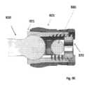
図6Aから図6Eは、本体又はチューリップ620、サドル650、球形コレット630、及びセットキャップ(図示せず)を含むロッドカップリングアセンブリ600の実施形態を示している。インプラント610の近位領域のねじ山611(図1B)は、図6Cに示す球形コレットの内面ねじとインターフェースする。図6Eに示すように、本体又はチューリップ620及びコレットアセンブリ630は、インプラント上をねじ込まれ、チューリップ620ドライバーは球形コレットの六角形又はトルクス(登録商標)に係合する。ねじ山は鋸歯状ねじ山にすることができる。球形コレットは、球形コレットが回転するときに半径方向にわずかに圧縮されるように、それに形成されたスリットを有する。そして、ロッドがチューリップに通って配置され、セットキャップをトルクで締めてロッドを所定の位置に固定することができる。6A-6E show an embodiment of a
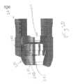
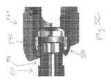
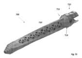
ロッドが固定インプラント(例えば本明細書に記載されているもののいずれか)のロッドカップリングアセンブリに固定された場合、チューリップ及びインプラントに曲げ荷重を加える場合がある。ロッドカップリングアセンブリ及び/又はインプラントが、曲げ荷重に抵抗するのに機能するように構成及び/又はサイズ設計されることが有益である場合がある。図7Aから図7Eは、インプラントの一部又はインプラント部分が本体又はチューリップとインターフェースし、特に、曲げ荷重に対してより多くの抵抗を提供するようにチューリップに対する支持を提供する、単なる例示的なロッドカップリングアセンブリを示している。図7Cにおいて、インプラント700のシャンク710は、インプラント可能な部分の細長い部材、例えば、PCT出願公開WO2020/168269における細長い内側部材(例えば、シャンク)のいずれかの例であり、その開示は、参照により本明細書に組み込まれる。外側スリーブ712は、一般に、少なくとも部分的に内側部材又はシャンク710の周りに配置された外側部材を指す。図7Dは、外側スリーブ712及び内側細長い本体710(例えば、シャンク部分)を含むインプラント700の非限定的な例を示している。スリーブは、近位領域713を含み、近位領域713は、その近位端が、チューリップ720の少なくとも一部の外側及びその周りに半径方向に配置され、チューリップに対する支持を提供するように、半径方向外向きに延びる構成を有する。チューリップは、外側スリーブのロック機構としても機能する。When a rod is secured to a rod coupling assembly of a fixed implant (such as any of those described herein), it may apply bending loads to the tulip and the implant. It may be beneficial for the rod coupling assembly and/or implant to be configured and/or sized to function to resist bending loads. FIGS. 7A-7E show merely exemplary rod coupling assemblies in which a portion of the implant or implant portion interfaces with a body or tulip and, in particular, provides support for the tulip to provide more resistance to bending loads. In FIG. 7C, the
この例示的な実施形態におけるスリーブ710は、PCT出願公開WO2020/168269の、例えば、図25Bの本体2504などを含む、本明細書の外側の細長い部材のいずれかであってもよい。更に、外側の細長い部材のいずれか(例えば、PCT出願公開WO2020/168269の図25Bの本体2504)は、図7Aから図7Eのスリーブ710がそうであるように、半径方向外向きに延びる近位領域を含むことができる。本実施形態におけるインプラントは、多種多様な形状及び構成を採用することができ、チューリップの外面とインターフェースするようにサイズ設計及び構成された近位に延びる領域713を含むことができる。The
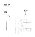
図8Aから図8Gは、図7Aから図7Eに示される実施形態にいくつかの点で類似しており、参照により任意の適切な開示を実施形態に組み込むことができるロッドカップリングアセンブリの実施形態を示す。この実施形態では、インプラントのスリーブ部分812は、図7Aから図7Eよりもチューリップ820の周りに大きく延びて、より多くの支持及び曲げ荷重に対するより多くの抵抗を提供する。この実施形態における球形構成要素は、図8Cに示される、インプラントの球形要素830として、インプラントの一部である。 図8D及び図8Eは、通常の負荷又は無負荷下でのチューリップ820とインプラントスリーブ812との間のクリアランス(clearance)870を示している。図8F及び図8Gは、極端な負荷のシナリオを示し、外側スリーブ812がどのようにブレース(brace)として機能し、内側シャンク810のネック領域の過度のゆがみを防止するかを示している。分かりやすくするために、ロッド及びセットスクリューは図示されていない。8A-8G show an embodiment of a rod coupling assembly similar in some respects to the embodiment shown in FIGS. 7A-7E, and in which any suitable disclosures may be incorporated by reference into the embodiment. In this embodiment, the
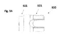
本明細書で議論されるように、いくつかのロッドカップリングアセンブリは、移植されると曲げ荷重を受ける可能性がある。図9Aから図9Fは、内側チューリップ部材及び外側チューリップ部材を含む例示的なチューリップを示している。図9Aから図9Fに示されるチューリップ920は、本明細書に示されたか又は記載されたもの以外のインプラントとともに使用することができる。チューリップ920は、外側チューリップ923と内側チューリップ921とを含む。図9Aから図9Fのチューリップは、反対に示されない限り、本明細書の任意の適切な実施形態に組み込むことができる。図9Aから図9Cは、ロッドカップリングアセンブリの他の部分がないチューリップ部材921及び923を示している。図9Dは、球形部材911が内側チューリップ921内に配置されている例示的なインプラント部分910を示している。図示のように、ロック解除位置における外側チューリップ923と内側チューリップ921との間のクリアランス925は、球形部材911が内側チューリップのインターフェース内にスナップすることを可能にする。そして、図9Eでは、ロッド980を配置した後、セットキャップ970を締めると、図示のように、内側チューリップ921が引っ張られ、外側チューリップ923に対して近位に移動する。図9Fに示されるように、外側チューリップ923と内側チューリップ921との間のテーパ状のインターフェースは、チューリップアセンブリが球形部材911にロックすることを可能にする。この最終的な構成では、外側チューリップは内側チューリップの広がりを防ぐのに役立つ。曲げ荷重を受けて、内側チューリップが、広がりしやすい場合がある。図示のように、ロッドカップリングアセンブリはまた、本明細書のサドルのいずれかのように、球形部材に前進することができるサドルを含むことができる。本実施の形態の内側チューリップ部材の例は、使用時に外側チューリップ部材に対して軸方向に移動するように構成されている。As discussed herein, some rod coupling assemblies may be subject to bending loads when implanted. FIGS. 9A-9F show an exemplary tulip including an inner tulip member and an outer tulip member. The
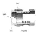
図10Aから図10Iは、図9Aから図9Fに示された実施形態と同様のロッドカップリングアセンブリであって、内側チューリップ部材及び外側チューリップ部材を備えるロッドカップリングアセンブリの例示的な実施形態を示す。図9Aから図9Fの実施形態による適切な開示のいずれか、例えば、セットキャップによって、内側チューリップが近位に引っ張られ、外側チューリップ内にする開示などは、反対に示されない限り、10A-10Iの開示に組み込まれることができる。示されるように、及び図9Aから図9Fの実施形態の場合のように、内側チューリップ1021は、それに少なくとも1つのスリット1025を備える遠位端を有し、軸方向移動中にある程度の広がり及び陥没することが可能となる。この実施形態において、1つの違いは、外側チューリップ1023の構成、及び最終的にセットキャップ1080を締める前に回転する(単に例として、例えば、4分の1又は1/4回転)ことができる方法である。外側チューリップ1023を回転させると、図に示すように、外側チューリップ1023の部分1025が内側チューリップの領域上に延び、これにより、チューリップアームに対する半径方向のより多くの支持を提供し、内側チューリップが広がる可能性を減少することができる。他の実施形態では、外側チューリップ及び/又は内側チューリップは、異なる構成を有することができ、4分の1回転よりも多く(90度)又は4分の1回転よりも少なく、例えば、0度から180度の間の角度で、例えば、5度から135度の間の角度で、例えば、45度から135度の間の角度で、例えば、90度の角度で回転することができる。10A-10I show an exemplary embodiment of a rod coupling assembly similar to the embodiment shown in FIGS. 9A-9F, but with an inner tulip member and an outer tulip member. Any of the appropriate disclosures according to the embodiment of FIGS. 9A-9F, such as a disclosure in which the inner tulip is pulled proximally into the outer tulip by the set cap, can be incorporated into the disclosure of 10A-10I, unless otherwise indicated. As shown, and as in the embodiment of FIGS. 9A-9F, the
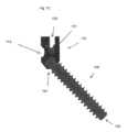
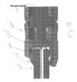
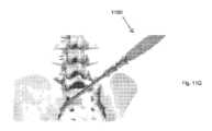
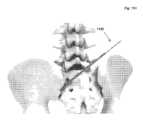
図11Aから図11Jは、例示的な骨インプラント1110及びチューリップアセンブリ1130を含む、ロッドカップリングシステム又はロッドカップリングアセンブリ1100の追加の例示的な実施形態を示す。代替のシステムは、骨インプラント1110及び他のタイプのチューリップアセンブリ(本明細書に記載されていないものを含む)を含むことができることを理解すべきである。代替のシステムは、チューリップサブアセンブリ1130及び他のタイプの骨インプラント(本明細書に記載されていないものを含む)を含むことができることを理解すべきである。更に、代替のシステムは、骨インプラント1110の1つ又は複数の特徴、並びにチューリップサブアセンブリの他のタイプ及び特徴(本明細書に記載されていないものを含む)を含むことができることを理解すべきである。代替のシステムは、チューリップサブアセンブリ1130の1つ又は複数の特徴、並びに骨インプラントの他のタイプ及び特徴(本明細書に記載されていないものを含む)を含むことができることを理解すべきである。11A-11J show additional exemplary embodiments of a rod coupling system or
チューリップアセンブリ及び骨インプラントを含む本明細書のシステム1100及び他の同様のシステムはまた、システムがチューリップアセンブリ及び骨インプラントに対して安定化ロッドをカップリング又は固定をするために使用することができるため、ロッドカップリングアセンブリ又はロッドカップリングシステムと称することができる。The
システム1100、骨インプラント1110、及びチューリップアセンブリ1130は、それらのテキスト記述がそれらの特徴を明示的に開示していなくても、本明細書に記載された他の特徴を含むと理解することができる。The
この実施形態の例示的な態様では、コレットと骨インプラントの近位領域との間のインターフェースは、チューリップにかかる軸方向の力(例えば、近位の力)に応じて、コレットの遠位端が拡張して緩む可能性を減少させるように、サイズ設計及び構成される。例えば、ロッドの動きによりチューリップに与えられる近位の力は、コレットに伝達される可能性があり、これは、時間の経過とともにコレットの遠位端を緩めたり、拡張させたりするような望ましくないことを引き起こす場合がある。In an exemplary aspect of this embodiment, the interface between the collet and the proximal region of the bone implant is sized and configured to reduce the likelihood of the distal end of the collet expanding and loosening in response to axial forces (e.g., proximal forces) applied to the tulip. For example, proximal forces applied to the tulip by movement of the rod can be transferred to the collet, which can undesirably cause the distal end of the collet to loosen and expand over time.
更に、図11Aから図11Jの例示的な実施形態におけるコレットとインプラントとのインターフェースは、ロッドの引き下げにより生じる軸方向の力に起因する緩む傾向に抵抗するか又は最小化にするように構成される。ロッドの引き下げは、一般的に、医師がロッドをチューリップから突き出して配置してから、解剖学的な修正を得るために、ロッドを引き下げる(つまり、ロッドをインプラントチューリップ内に引き込める)場合が挙げられる。このステップは、コレットが所定の位置に固定される前に行われる。これらの引き下げはインプラントに大きな力を加え、コレットはまだ固定されていないため、コレットがバラバラになる可能性がある。図11Aから図11Jのコレットとインプラントとのインターフェースは、これらの引き下げの間に、コレットが閉じたままであることを確実にする、又はコレットが閉じたままである可能性を高めるようにサイズ設計及び構成されたようなインターフェースの例である。Furthermore, the collet-implant interface in the exemplary embodiment of Figs. 11A-11J is configured to resist or minimize the tendency to loosen due to the axial force caused by the pull-down of the rod, which typically occurs when the surgeon places the rod protruding from the tulip and then pulls the rod down (i.e., retracts the rod into the implant tulip) to obtain an anatomical correction. This step occurs before the collet is locked into place. These pull-downs apply significant forces to the implant and, because the collet is not yet locked, the collet may break apart. The collet-implant interface of Figs. 11A-11J is an example of such an interface sized and configured to ensure or increase the likelihood that the collet will remain closed during these pull-downs.
これらの力に応じてコレットが緩むか又は拡張する可能性を低減するために、これらのシナリオでは、インプラントアンダーカットは、互いに平行でない表面1114と表面1114に面するコレット表面との間に、ギャップ1102(図11E)を形成又は生成する。コレット表面は長手軸に直交していてもよい。軸方向の力がチューリップに加えられると、ギャップ1102は、コレットの垂直面に加えられる遠位方向の力が少なくなるように空間を提供し、コレットの拡張及び緩みの可能性を低減させる。コレットの拡張及び緩みの可能性を低減させるのは、すべての点で類似し、骨インプラントの長手軸LAに直交する半径方向に延びる表面1114を有するシステム、又はギャップが存在しないシステムと比較して言及したものである。To reduce the likelihood of the collet loosening or expanding in response to these forces, in these scenarios, the implant undercut forms or creates a gap 1102 (FIG. 11E) between the
骨インプラント陥凹1112の近位端のアンダーカットは、様々な方法で説明することができる。アンダーカットは、骨インプラントの長手軸に対して90度未満の角度を成して配置された半径方向に延びる表面(例えば、1114)を含む、インプラントの近位領域にある陥凹のコレット受容領域1112として説明することができ、角度は、図11Dの角度αとして示されているように、半径方向に延びる表面に対して遠位で測定したものである。図11Dでは、角度はまた、軸方向に延びる表面1118に対して示されているが、軸方向に延びる表面1118は、示されるように平坦なものである必要はなく、曲面であってもよい。なお、本明細書の任意の実施形態において、表面1114又はその延長部は、インプラントの長軸又は長軸に平行な軸と角度を形成してもよく、当該角度は、両方の場合において同じ角度αであってもよい。The undercut at the proximal end of the
本明細書のアンダーカットはまた、本明細書において機能的に記載及び主張することができる。例えば、あらゆる点で類似しているが、骨インプラントの長手軸に直交する半径方向に延びる表面を有するシステムに比較して、半径方向に延びる表面は角度が付けられることで、コレットの遠位端が軸方向の力に応じて拡張し、緩くなる可能性を低減することができる。The undercuts herein may also be described and claimed functionally herein. For example, the radially extending surfaces may be angled to reduce the likelihood that the distal end of the collet will expand and become loose in response to axial forces, as compared to a system that is similar in all respects but has radially extending surfaces perpendicular to the longitudinal axis of the bone implant.
本明細書のアンダーカットは、半径方向に陥凹のコレット受容領域を含む近位領域、又は長軸に対して90度未満の角度を成して配置された半径方向に延びる表面を含む領域を含むと説明することができる。本明細書のアンダーカットは、半径方向に延びる表面(例えば、1114)の両側にある遠位の軸方向に延びる表面(例えば、表面1118)と近位の軸方向に延びる表面(例えば、1116)とを有する半径方向に陥凹のコレット受容領域を含む近位領域を含むと説明することができる。近位の軸方向に延びる表面は、遠位の軸方向に延びる表面よりも長軸から更に半径方向外側に配置され、その例が図11D及び11Eに示されている。An undercut herein can be described as including a proximal region that includes a radially recessed collet receiving area, or a region that includes a radially extending surface disposed at an angle less than 90 degrees relative to the longitudinal axis. An undercut herein can be described as including a proximal region that includes a radially recessed collet receiving area having a distal axially extending surface (e.g., surface 1118) and a proximal axially extending surface (e.g., 1116) on either side of a radially extending surface (e.g., 1114). The proximal axially extending surface is disposed further radially outward from the longitudinal axis than the distal axially extending surface, examples of which are shown in Figures 11D and 11E.
アンダーカットは、半径方向に延びる表面1114とそこから延びる1つ又は複数の表面、例えば、軸方向に延びる表面1118及び軸方向に延びる表面1116など、を含むと考えることができる。この例では、アンダーカットは、図11D及び図11Eに示されるように、半径方向に延びる表面1114の近位端よりも更に遠位に延びる軸方向に延びる表面1116の遠位端を含む。The undercut can be considered to include radially extending
本明細書に記載されるように、軸方向に延びる表面は、必ずしもインプラントの長軸と平行である必要はなく、むしろそれに対してある角度を成し、依然として軸方向に延びると考えられるか、又は曲面であり、依然として軸方向に延びると考えられる。As described herein, an axially extending surface need not necessarily be parallel to the long axis of the implant, but rather may be at an angle thereto and still be considered to extend axially, or may be curved and still be considered to extend axially.
コレット1134又は本明細書の任意のコレットは、一般的なコレット特徴、例えば、コレットの遠位端の拡張及び圧潰を可能とするように、それを通して形成された線形スリット又はスロットを含むことができる。これにより、コレットがインプラントの近位端上を前進するにつれ、コレットが拡張することができる。いくつかの実施形態では、インプラントの近位端は、例えば、面取りされた表面1120(図11C)を有することによって、コレットの拡張を容易にすることができ、これは、コレットがインプラントの近位端上を遠位にスライドするときにコレットの遠位端を拡張するのに役立つことができる。コレットインプラントインターフェース領域1135(図11B)が陥凹領域1112に対して遠位に前進すると、スリット/スロットによるコレットの遠位端の圧潰性のため、コレットインプラントインターフェース領域1135は陥凹1112内に陥没する。図11A、11B、及び11Eに示されるように、陥凹領域1112の所定の位置にスナップ又は陥没することにより、インプラントの近位領域1111に対してコレットが所定の位置に固定される。チューリップ1132は、固定ネジがチューリップ内にねじ込まれ(図11Aに示されている内面ねじ)、ロッドが所定の位置に固定されるまで(図11A-11Iには図示せず)、コレット1134に対して移動できるが、本明細書の任意のロッドは、チューリップの側面の開口部を通って配置することができる。
図11Bに示されるコレットインプラントインターフェース領域1135は、コレットの半径方向内側に突出するインプラントインターフェース領域の例であり、コレット1134の陥凹領域1112に配置されてインターフェースすることが示されている。インプラント表面1114に面している、図11Eに示すコレット1134の半径方向に延びる表面は、コレットの中心軸に直交することができる。他の実施形態では、コレット1134の半径方向に延びる表面は、長軸に対して角度を成して配置することができる。Collet-
いくつかの実施形態では、コレットのインプラントインターフェース領域の半径方向に延びる表面(例えば、図11Eに示すように)は、コレットの長手軸に直交している。In some embodiments, the radially extending surface of the implant interface region of the collet (e.g., as shown in FIG. 11E) is perpendicular to the longitudinal axis of the collet.
いくつかの実施形態では、インプラントの陥凹のコレット受容領域の半径方向に延びる表面は、インプラントの長手軸に対して85度未満の角度(例えば、図11Dの角度α)を成して配置される。いくつかの実施形態では、角度αは、インプラントの長手軸に対して45度より大きくてもよい。いくつかの実施形態では、角度αは、インプラントの長手軸に対して75度よりも大きい。いくつかの実施形態では、角度は、インプラントの長手軸に対して70度から89度である。In some embodiments, the radially extending surfaces of the collet receiving area of the implant recess are disposed at an angle of less than 85 degrees (e.g., angle α in FIG. 11D ) relative to the longitudinal axis of the implant. In some embodiments, angle α may be greater than 45 degrees relative to the longitudinal axis of the implant. In some embodiments, angle α is greater than 75 degrees relative to the longitudinal axis of the implant. In some embodiments, the angle is between 70 degrees and 89 degrees relative to the longitudinal axis of the implant.
いくつかの実施形態では、陥凹のコレット受容領域(例えば、領域1112)は、陥凹の域1112に軸方向に隣接するインプラントの外形寸法に対して0.1mmから2.0mmの深さを有する。In some embodiments, the collet receiving area of the recess (e.g., area 1112) has a depth of 0.1 mm to 2.0 mm relative to the outer dimension of the implant axially adjacent to the recessed
本明細書の実施形態のいずれかにおいて、骨インプラントの近位領域は、図11Aから図11Jの例に示されるように、外面ねじが設けられていなくてもよい。In any of the embodiments herein, the proximal region of the bone implant may not be externally threaded, as shown in the examples of Figures 11A-11J.
いくつかの実施形態において、インプラントの陥凹のコレット受容領域は、図11Cに示されるように、骨インプラントの周りの環状構成を有する。In some embodiments, the collet receiving area of the implant recess has an annular configuration around the bone implant, as shown in FIG. 11C.
本明細書に示されていなくても、本明細書の任意のシステムのコレットは、部分的な球形構成を有することができ、チューリップは、対応する内面を有することができる。コレットとチューリップとの表面は、コレットがチューリップ内に配置されたときに互いにインターフェースするように一緒にサイズ設計及び構成される。チューリップの内面とコレットの外面との両方は、図11Aから図11Jの実施形態のように、移動可能な状態でコレットに対してチューリップを移動可能にするようにサイズ設計及び構成することができる。Although not shown herein, the collet of any system herein can have a partial spherical configuration and the tulip can have a corresponding inner surface. The surfaces of the collet and tulip are together sized and configured to interface with one another when the collet is placed within the tulip. Both the inner surface of the tulip and the outer surface of the collet can be sized and configured to move the tulip relative to the collet in a movable manner, such as in the embodiment of Figures 11A-11J.
本明細書のチューリップアセンブリ又はロッドカップリングアセンブリのいずれかは、チューリップ内に、且つ、少なくとも部分的に前記コレットの近位に配置するようにサイズ設計及び構成されたサドルを更に含むことができる。本明細書のサドルは、コレットの湾曲した近位領域と噛み合うように成形された湾曲の内面を備える遠位領域を有することができる。本明細書のサドルは、細長いロッド(例えば、図11Aから図11Jの実施形態に示されたように)の外面とインターフェースするように成形された構成を有する陥凹の領域を備える近位端を有することができる。Any of the tulip assemblies or rod coupling assemblies herein may further include a saddle sized and configured to be disposed within the tulip and at least partially proximal to the collet. The saddle herein may have a distal region with a curved inner surface shaped to mate with the curved proximal region of the collet. The saddle herein may have a proximal end with a recessed region having a shaped configuration to interface with an outer surface of an elongated rod (e.g., as shown in the embodiment of FIGS. 11A-11J).
本明細書のコレットのいずれかは、それに形成された1つ又は複数の開口部を有することができる。図11Aのチューリップ内にセットスクリュー外面ねじ込むと、ロッド(図示せず)に力が加わり、それによってサドルに力が加わる。これは、コレット/チューリップのインターフェースとともに、インプラントの近位端の周りでコレットの圧縮を生じさせる。チューリップが所望の角度になったら、セットスクリューを本明細書に記載されているように前進させ、ロッド及びインプラントに対してチューリップを本質的に安定させることができる。Any of the collets herein can have one or more openings formed therein. When a set screw is externally threaded into the tulip of FIG. 11A, a force is applied to the rod (not shown), which in turn applies a force to the saddle. This, along with the collet/tulip interface, causes compression of the collet around the proximal end of the implant. Once the tulip is at the desired angle, the set screw can be advanced as described herein, essentially stabilizing the tulip relative to the rod and implant.
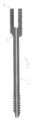
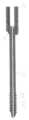
例示的な骨インプラントが本明細書に示されているが、本明細書のロッドカップリングアセンブリの一部であり得る骨インプラントは、多種多様な骨インプラントとして構成され、サイズ設計することができる。例えば、本明細書の骨インプラントは、それらの長さの少なくとも一部に沿ってねじ山が設けられてもよく、又はそれらにはねじ山が設けられなくてもよい。本明細書の骨インプラントは、1つ又は複数の腸骨、又は仙骨、又は他の椎骨内に進むように構成することができる。Although exemplary bone implants are shown herein, the bone implants that may be part of the rod coupling assemblies herein can be configured and sized as a wide variety of bone implants. For example, the bone implants herein can be threaded along at least a portion of their length or they can be unthreaded. The bone implants herein can be configured to advance into one or more ilium, or sacrum, or other vertebrae.
本開示の一態様は、関連するチューリップアセンブリを有する又は有さない骨インプラントである。骨インプラントは、長軸及び近位領域を備える細長い本体を有することができ、近位領域は、チューリップアセンブリのコレット内でカップリングされるようにサイズ設計及び構成されている。インプラントの近位領域は、半径方向に陥凹のコレット受容領域(例えば、領域1112)を含むことができ、陥凹のコレット受容領域は、インプラントの長軸(又は中心)に対して90度未満の角度を成して配置された半径方向に延びる表面(例えば、表面1114)を含む。インプラントのコレット受容領域はまた、遠位の軸方向に延びる表面と近位の軸方向に延びる表面とを含み、遠位の軸方向に延びる表面と近位の軸方向に延びる表面とは、半径方向に延びる表面の両側にあり、近位の軸方向に延びる表面は、遠位の軸方向に延びる表面よりも長軸又は中心軸から更に半径方向外側に配置される。One aspect of the present disclosure is a bone implant with or without an associated tulip assembly. The bone implant can have an elongate body with a longitudinal axis and a proximal region, the proximal region sized and configured to couple within a collet of the tulip assembly. The proximal region of the implant can include a radially recessed collet receiving region (e.g., region 1112) that includes a radially extending surface (e.g., surface 1114) disposed at an angle of less than 90 degrees relative to the longitudinal axis (or center) of the implant. The collet receiving region of the implant also includes a distal axially extending surface and a proximal axially extending surface, the distal axially extending surface and the proximal axially extending surface being on opposite sides of the radially extending surface, the proximal axially extending surface being disposed further radially outward from the longitudinal axis or center axis than the distal axially extending surface.
本明細書の任意の骨インプラントの近位端は、図11Cに示される例において1120として符号付けされているような面取りされた構成を有することができる。The proximal end of any bone implant herein can have a chamfered configuration, such as that shown in the example in FIG. 11C, labeled as 1120.
遠位の軸方向に延びる表面(例えば、表面1118)は、インプラントの長軸に対して、0度から25度の角度を成して配置されてもよい。The distal axially extending surface (e.g., surface 1118) may be disposed at an angle of 0 degrees to 25 degrees relative to the long axis of the implant.
本明細書の骨インプラントのいずれかは、図11Aに示されるような、内面ねじを備える内腔を有する近位領域を含むことができる。モジュール式チューリップアセンブリとしてカップリングされるいくつかの実施形態では、内面ねじは、ガイドロッド上の外ねじとインターフェースするようにサイズ設計及び構成され、ガイドロッドは、コレットを含むモジュラーチューリップアセンブリの細長い本体の近位領域上の前進を容易にすることができる。Any of the bone implants herein can include a proximal region having an internal lumen with internal threads, as shown in FIG. 11A. In some embodiments coupled as a modular tulip assembly, the internal threads are sized and configured to interface with external threads on a guide rod, which can facilitate advancement over the proximal region of the elongated body of the modular tulip assembly, including the collet.
本明細書のアンダーカットレッジ構成のいずれは、上面を有するがけ(cliff)と同様に説明することができ、その少なくとも一部は、がけの半径方向に延びる壁部分に対して遠位に延びる。Any of the undercut ledge configurations herein can be described similarly as a cliff having an upper surface, at least a portion of which extends distally relative to the radially extending wall portion of the cliff.
本明細書のチューリップアセンブリは、挿入前にインプラントにカップリングすることができ、又はインプラントが少なくとも部分的に骨内に植え込まれた後にモジュール式でインプラントにカップリングすることができる。骨インプラントが植え込まれる前にインプラントにモジュール式でカップリングされるかどうかにかかわらず、チューリップアセンブリは、本明細書の任意のチューリップアセンブリの特徴のいずれかを含むことができる。The tulip assemblies herein may be coupled to the implant prior to insertion or may be modularly coupled to the implant after the implant is at least partially implanted within the bone. Whether or not the tulip assembly is modularly coupled to the implant prior to implantation of the bone implant, the tulip assembly may include any of the features of any of the tulip assemblies herein.
本明細書のチューリップは、既存のチューリップに共通する任意の適切な特徴を含むことができる。図11Aから図11Jは、それを通って細長いロッドを受け入れるようにサイズ設計及び構成された第1の側面開口部及び第2の側面開口部を備える例示的なチューリップを示している。図11Aから図11Jは、半径方向内側に突出するインプラントインターフェース領域(例えば、領域1135)を含むコレットを備える例示的なチューリップアセンブリを示し、図示のように、突出するインプラントインターフェース領域は、コレットの長手軸に対して角度を成して配置された半径方向に延びる表面と、半径方向に延びる表面と交わる軸方向に延びる表面とを含む。半径方向内側への突出は、コレットが骨インプラントの近位領域上を前進する(又はインプラントがコレット内で軸方向に移動する)ときに、コレットの遠位端が骨インプラントの近位領域における陥凹領域に向かって陥没することを容易にする。また、本明細書のチューリップアセンブリのいずれかは、チューリップ内に配置され、少なくとも部分的に前記コレットの近位に配置されるようにサイズ設計されたサドルを含むことができる。サドルのいずれかは、コレットの湾曲した近位領域と噛み合うように成形された湾曲した内面を備える遠位領域を有することができる。本明細書の任意のサドルは、細長いロッドとインターフェースするように成形された構成を有する陥凹の領域を備える近位端を有することができる。The tulips herein may include any suitable features common to existing tulips. FIGS. 11A-11J show an exemplary tulip with a first side opening and a second side opening sized and configured to receive an elongated rod therethrough. FIGS. 11A-11J show an exemplary tulip assembly with a collet including a radially inwardly protruding implant interface region (e.g., region 1135), as shown, the protruding implant interface region includes a radially extending surface disposed at an angle to the longitudinal axis of the collet and an axially extending surface intersecting the radially extending surface. The radially inward protrusion facilitates the distal end of the collet to recess toward a recessed region in the proximal region of the bone implant as the collet advances over the proximal region of the bone implant (or the implant moves axially within the collet). Any of the tulip assemblies herein may also include a saddle disposed within the tulip and sized to be disposed at least partially proximal to the collet. Any of the saddles can have a distal region with a curved inner surface shaped to mate with the curved proximal region of the collet. Any of the saddles herein can have a proximal end with a recessed region having a configuration shaped to interface with the elongated rod.
本明細書のチューリップアセンブリのいずれかは、それに1つ又は複数の開口部又はスリットを有するコレットを含むことによって、コレットが、チューリップ及びサドルからコレットに加えられる力に応じて半径方向内向きの締付力を加えることを可能にする。Any of the tulip assemblies herein may include a collet having one or more openings or slits therein, thereby allowing the collet to apply a radially inward clamping force in response to forces applied to the collet from the tulip and saddle.
本明細書のチューリップアセンブリのいずれかは、0.1mmから2.0mmの高さを有する半径方向内向きの突起(例えば、インプラントインターフェース領域1135)を含むことができ、その寸法は、本明細書の陥凹のインプラント領域のいずれかと実質的に同じ深さであると考えることができる。Any of the tulip assemblies herein may include a radially inward protrusion (e.g., implant interface region 1135) having a height of 0.1 mm to 2.0 mm, the dimensions of which may be considered to be substantially the same depth as any of the recessed implant regions herein.
本明細書のコレットのいずれかは、図11Eに例示的に示されるように、コレットの長軸に直交する半径方向に延びる表面を含む突起を含むことができる。Any of the collets herein may include a protrusion that includes a radially extending surface perpendicular to the longitudinal axis of the collet, as shown illustratively in FIG. 11E.
米国特許第8,84,5693号及び第9,655,656号に開示されているシステムコンポーネント及び特徴の更なる開示は、本明細書の開示に関連することができ、その開示の全体は、あらゆる目的のために参照により本明細書に組み込まれる。Further disclosure of system components and features disclosed in U.S. Patent Nos. 8,845,693 and 9,655,656 may be relevant to the disclosure herein, the entire disclosures of which are incorporated herein by reference for all purposes.
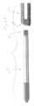
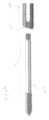
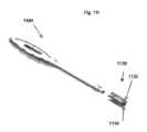
図11Fから図11Jは、モジュラーチューリップアセンブリをインプラントにカップリングするための単なる例示的な方法のステップ及び送達ツールを示している。FIGS. 11F-11J show merely exemplary method steps and delivery tools for coupling a modular tulip assembly to an implant.
図11F及び図11Gは、インプラント送達ツール1190を使用して植え込まれているインプラント1110を示している。インプラント送達ツール1190が取り外された後、ガイドロッド1192は、図11Hに示すように、ガイドロッドが骨インプラントから近位に延びるように、骨インプラントの近位領域にカップリングされる。ガイドロッドが取り外された後、図11I及び図11Jに示すように、チューリップアセンブリ1130にカップリングされたチューリップ送達ツール1194を使用して、チューリップアセンブリを、ガイドロッド上を前進させる。この方法は、骨インプラントの近位領域の近位端に対してコレットを前進させることと、コレットが骨インプラントの近位領域上を前進するときにコレットの遠位端を拡張させることとを更に含むことができる。この方法は、コレットの半径方向内側の突出が半径方向内側に移動して骨インプラントの陥凹の領域に移動するまで、コレットを、骨インプラントの近位領域上を続けて前進させることを更に含み、骨インプラントの陥凹の領域は、アンダーカットレッジ構成を備える近位端を有する。11F and 11G show an
いくつかの実施形態では、骨インプラントは、それに既にカップリングされているチューリップアセンブリとともに植え込まれる。In some embodiments, the bone implant is implanted with the tulip assembly already coupled to it.
Claims (15)
Translated fromJapanese前記骨インプラントは、遠位領域から離間した近位領域を有し、前記近位領域は、チューリップアセンブリとインターフェースするようにサイズ設計及び構成され、前記チューリップアセンブリは、チューリップと、少なくとも部分的に前記チューリップ内に配置されるようにサイズ設計及び構成されたコレットとを含み、
前記チューリップアセンブリは、それを通って安定化ロッドを受け入れるようにサイズ設計及び構成された開口部を有し、
前記骨インプラントの近位領域は、半径方向に陥凹のコレット受容領域を含み、前記陥凹のコレット受容領域は、内部で前記コレットの半径方向内側に突出するインプラントインターフェース領域を受け入れるようにサイズ設計及び構成され、前記陥凹のコレット受容領域は、前記骨インプラントの長手軸に対して90度未満の角度を成して配置された半径方向に延びる表面を含み、前記角度は、半径方向に延びる表面に対して遠位で測定され、
前記コレットの前記インプラントインターフェース領域は、コレットの長手軸に対して角度を成して配置された半径方向に延びる表面を含み、前記インプラントインターフェース領域が前記陥凹のコレット受容領域とインターフェースされたときに、前記インプラントインターフェース領域の前記半径方向に延びる表面は、前記陥凹のコレット受容領域の半径方向に延びる表面に面するように配置され、前記インプラントインターフェース領域の前記半径方向に延びる表面と、前記陥凹のコレット受容領域の前記半径方向に延びる表面との間にギャップが形成される、
システム。 1. A rod coupling system comprising a bone implant and a tulip assembly for securing a rod to the bone implant,
the bone implant has a proximal region spaced from a distal region, the proximal region sized and configured to interface with a tulip assembly including a tulip and a collet sized and configured to be at least partially disposed within the tulip;
the tulip assembly having an opening sized and configured to receive a stabilization rod therethrough;
a proximal region of the bone implant including a radially recessed collet receiving area sized and configured to receive therein a radially inwardly projecting implant interface region of the collet, the recessed collet receiving area including a radially extending surface disposed at an angle of less than 90 degrees relative to a longitudinal axis of the bone implant, the angle being measured distally to the radially extending surface;
the implant interface region of the collet includes a radially extending surface disposed at an angle relative to a longitudinal axis of the collet, the radially extending surface of the implant interface region being disposed such that when the implant interface region is interfaced with the collet receiving region of the recess, the radially extending surface of the implant interface region faces the radially extending surfaceof the collet receiving region of the recess such that a gap is formed between the radially extending surface of the implant interface region and the radially extending surface of the collet receiving region of the recess .
system.
請求項1に記載のシステム。 the radially extending surface of the implant interface region of the collet is perpendicular to a longitudinal axis of the collet;
The system of claim 1 .
請求項1に記載のシステム。 the radially extending surface of the collet receiving area of the recess is disposed at an angle of less than 85 degrees relative to a longitudinal axis of the bone implant;
The system of claim 1 .
請求項1に記載のシステム。 the radially extending surface of the collet receiving area of the recess is disposed at an angle of greater than 45 degrees relative to a longitudinal axis of the bone implant;
The system of claim 1 .
請求項1に記載のシステム。 the radially extending surface of the collet receiving area of the recess is disposed at an angle of greater than 75 degrees relative to a longitudinal axis of the bone implant;
The system of claim 1 .
請求項1に記載のシステム。 the radially extending surface of the collet receiving area of the recess is disposed at an angle of between 70 degrees and 89 degrees relative to the longitudinal axis of the bone implant;
The system of claim 1 .
請求項1に記載のシステム。 the tulip assembly is modular and adapted to be delivered separately from the bone implant and movably secured to the bone implant after the bone implant is at least partially implanted within the bone;
The system of claim 1 .
前記チューリップアセンブリは、前記ねじ山付きガイドロッド上を前進し、前記骨インプラントの前記近位端上を前進して、前記チューリップアセンブリと前記骨インプラントとを移動可能に固定するように適合されている、
請求項7に記載のシステム。 a proximal end of the bone implant including internal threads sized and configured to receive an internally threaded guide rod;
the tulip assembly is adapted to be advanced over the threaded guide rod and over the proximal end of the bone implant to movably secure the tulip assembly and the bone implant.
The system of claim 7.
前記陥凹のコレット受容領域により、前記コレットが前記骨インプラントの前記近位領域上を遠位方向に前進するときに、前記コレットの半径方向内側に突出する前記インプラントインターフェース領域が半径方向内側に移動して前記陥凹のコレット受容領域内に移動する、
請求項1に記載のシステム。 the proximal region of the bone implant includes a chamfered proximal end to facilitate expansion of the distal end of the collet as the collet is advanced over the chamfered proximal end;
a collet receiving area of the recess such that as the collet is advanced distally over the proximal region of the bone implant, the radially inwardly projecting implant interface region of the collet moves radially inwardly into the collet receiving area of the recess.
The system of claim 1 .
前記陥凹のコレット受容領域により、前記コレットが前記骨インプラント上を更に前進するとき、前記コレットの半径方向内側に突出するインプラントインターフェース領域は、静止状態に向けて前記陥凹のコレット受容領域内に戻る、
請求項9に記載のシステム。 the proximal region of the bone implant is configured to facilitate opening of the distal end of the collet as the collet is advanced over the proximal end;
a collet receiving area of the recess such that as the collet is further advanced over the bone implant, a radially inwardly protruding implant interface area of the collet moves back into the collet receiving area of the recess toward a resting state.
The system of claim9 .
請求項1に記載のシステム。 The collet receiving area of the recess has a depth of 0.1 mm to 2.0 mm.
The system of claim 1 .
請求項1に記載のシステム。 the proximal region of the bone implant is free of external threads;
The system of claim 1 .
請求項1に記載のシステム。 the proximal region of the bone implant having an outermost sleeve surface sized and configured to extend over at least a portion of the distal end of the tulip;
The system of claim 1 .
請求項13に記載のシステム。 the outermost sleeve surface being a surface of an outer implant sleeve, the outer implant sleeve being disposed about an inner shank of the implant;
The system of claim 13.
請求項1に記載のシステム。 the collet receiving area of the recess has an annular configuration around the bone implant;
The system of claim 1 .
Priority Applications (1)
| Application Number | Priority Date | Filing Date | Title |
|---|---|---|---|
| JP2025034945AJP2025081770A (en) | 2019-11-21 | 2025-03-05 | Rod coupling assembly for bone stabilization structure |
Applications Claiming Priority (3)
| Application Number | Priority Date | Filing Date | Title |
|---|---|---|---|
| US201962938546P | 2019-11-21 | 2019-11-21 | |
| US62/938,546 | 2019-11-21 | ||
| PCT/US2020/061849WO2021102429A1 (en) | 2019-11-21 | 2020-11-23 | Rod coupling assemblies for bone stabilization constructs |
Related Child Applications (1)
| Application Number | Title | Priority Date | Filing Date |
|---|---|---|---|
| JP2025034945ADivisionJP2025081770A (en) | 2019-11-21 | 2025-03-05 | Rod coupling assembly for bone stabilization structure |
Publications (2)
| Publication Number | Publication Date |
|---|---|
| JP2023502278A JP2023502278A (en) | 2023-01-23 |
| JP7646654B2true JP7646654B2 (en) | 2025-03-17 |
Family
ID=75980921
Family Applications (2)
| Application Number | Title | Priority Date | Filing Date |
|---|---|---|---|
| JP2022529720AActiveJP7646654B2 (en) | 2019-11-21 | 2020-11-23 | Rod coupling assembly for bone stabilization construct - Patent application |
| JP2025034945APendingJP2025081770A (en) | 2019-11-21 | 2025-03-05 | Rod coupling assembly for bone stabilization structure |
Family Applications After (1)
| Application Number | Title | Priority Date | Filing Date |
|---|---|---|---|
| JP2025034945APendingJP2025081770A (en) | 2019-11-21 | 2025-03-05 | Rod coupling assembly for bone stabilization structure |
Country Status (5)
| Country | Link |
|---|---|
| US (1) | US12419668B2 (en) |
| EP (1) | EP4061262A1 (en) |
| JP (2) | JP7646654B2 (en) |
| AU (1) | AU2020386985A1 (en) |
| WO (1) | WO2021102429A1 (en) |
Families Citing this family (12)
| Publication number | Priority date | Publication date | Assignee | Title |
|---|---|---|---|---|
| US20180228621A1 (en) | 2004-08-09 | 2018-08-16 | Mark A. Reiley | Apparatus, systems, and methods for the fixation or fusion of bone |
| US10363140B2 (en) | 2012-03-09 | 2019-07-30 | Si-Bone Inc. | Systems, device, and methods for joint fusion |
| US10166033B2 (en) | 2014-09-18 | 2019-01-01 | Si-Bone Inc. | Implants for bone fixation or fusion |
| ES3011907T3 (en) | 2018-03-28 | 2025-04-08 | Si Bone Inc | Threaded implants for use across bone segments |
| US10813769B2 (en) | 2018-07-24 | 2020-10-27 | DePuy Synthes Products, Inc. | Baseplate of a modular shoulder joint prosthesis and related methods for implanting the same |
| EP4613244A2 (en) | 2019-02-14 | 2025-09-10 | SI-Bone Inc. | Implants for spinal fixation and or fusion |
| AU2020392121B2 (en) | 2019-11-27 | 2025-05-22 | Si-Bone, Inc. | Bone stabilizing implants and methods of placement across SI joints |
| EP4072452A4 (en) | 2019-12-09 | 2023-12-20 | SI-Bone, Inc. | Sacro-iliac joint stabilizing implants and methods of implantation |
| WO2021127251A1 (en)* | 2019-12-17 | 2021-06-24 | Jackson Roger P | Bone anchor assembly with closed ring retainer and internal snap ring |
| EP4259015A4 (en) | 2020-12-09 | 2024-09-11 | SI-Bone, Inc. | SACROILIAC JOINT STABILIZATION IMPLANTS AND METHODS OF IMPLANTATION |
| WO2025038769A1 (en) | 2023-08-15 | 2025-02-20 | Si-Bone Inc. | Pelvic stabilization implants, methods of use and manufacture |
| KR102733824B1 (en)* | 2023-08-25 | 2024-11-25 | 박경우 | Bio-flexible spinal implant assembly with detachable head modules and their continuous connection assembly |
Citations (4)
| Publication number | Priority date | Publication date | Assignee | Title |
|---|---|---|---|---|
| US20060036252A1 (en) | 2004-08-12 | 2006-02-16 | Baynham Bret O | Polyaxial screw |
| WO2008153723A1 (en) | 2007-05-23 | 2008-12-18 | Jackson Roger P | Polyaxial bone screw with shank-retainer inset capture |
| JP2011041802A (en) | 2009-08-20 | 2011-03-03 | Biedermann Motech Gmbh & Co Kg | Bone anchoring device, tool and method for assembling the same and tool for inserting the same |
| JP2011512939A (en) | 2008-02-27 | 2011-04-28 | 崔 吉運 | Buffer type spinal screw device |
Family Cites Families (1023)
| Publication number | Priority date | Publication date | Assignee | Title |
|---|---|---|---|---|
| US2675801A (en) | 1954-04-20 | Intramedbllary nail | ||
| US1951278A (en) | 1932-02-13 | 1934-03-13 | Ericsson Ernst Axel Johan | Fracture nail |
| US2136471A (en) | 1937-06-30 | 1938-11-15 | Rudolph H Schneider | Bone pin |
| US2243717A (en) | 1938-09-20 | 1941-05-27 | Moreira Franciseo Elias Godoy | Surgical device |
| US2414882A (en) | 1943-09-24 | 1947-01-28 | Herschel Leiter H | Fracture reduction apparatus |
| US2562419A (en) | 1948-04-05 | 1951-07-31 | George L Ferris | Expansion nut setting tool |
| US2697433A (en) | 1951-12-04 | 1954-12-21 | Max A Zehnder | Device for accurately positioning and guiding guide wires used in the nailing of thefemoral neck |
| US3076453A (en) | 1961-01-16 | 1963-02-05 | Raymond G Tronzo | Hip nail |
| US3506982A (en) | 1965-06-21 | 1970-04-21 | Cleveland Clinic | Endoprosthetic joints |
| US3709218A (en) | 1970-04-24 | 1973-01-09 | W Halloran | Combination intramedullary fixation and external bone compression apparatus |
| US3694821A (en) | 1970-11-02 | 1972-10-03 | Walter D Moritz | Artificial skeletal joint |
| US3744488A (en) | 1971-06-08 | 1973-07-10 | J Cox | Bone splint |
| US4059115A (en) | 1976-06-14 | 1977-11-22 | Georgy Stepanovich Jumashev | Surgical instrument for operation of anterior fenestrated spondylodessis in vertebral osteochondrosis |
| SE7707082L (en) | 1976-07-06 | 1978-01-07 | Scheicher Hans | DRILLING HEAD AND BONE DRILL, IN PARTICULAR FOR THE PREPARATION OF BENCH CAVITES FOR RECEIVING ENOSSAL PROTETICAL ELEMENTS, AND AN ENOSSAL ODONTOLOGICAL HALF IMPLANT |
| US4156943A (en) | 1977-08-24 | 1979-06-05 | Collier John P | High-strength porous prosthetic device and process for making the same |
| AT358715B (en) | 1978-09-04 | 1980-09-25 | Plansee Metallwerk | BUTCHING AND REJECTING DEVICE FOR BONE MARKING NAIL |
| US4341206A (en) | 1978-12-19 | 1982-07-27 | Synthes Ag | Device for producing a hole in a bone |
| DE2901962A1 (en) | 1979-01-19 | 1980-07-24 | Max Bernhard Ulrich | DEVICE FOR ILIOSACRAL TRANSFIXATION OF A POOL FRACTURE |
| DE3064260D1 (en) | 1979-07-25 | 1983-08-25 | Univ Exeter | Plugs for the medullary canal of a bone |
| US4399813A (en) | 1981-01-22 | 1983-08-23 | Barber Forest C | Apparatus and method for removing a prosthesis embedded in skeletal bone |
| US4501269A (en) | 1981-12-11 | 1985-02-26 | Washington State University Research Foundation, Inc. | Process for fusing bone joints |
| DE8214493U1 (en) | 1982-05-18 | 1982-09-09 | Howmedica International, Inc. Zweigniederlassung Kiel, 2301 Schönkirchen | Bone nail for the treatment of fractures in the proximal thigh area |
| US4475545A (en) | 1982-12-06 | 1984-10-09 | Ender Hans G | Bone-nail |
| JPS59200642A (en) | 1983-04-28 | 1984-11-14 | 三菱鉱業セメント株式会社 | Bone fixing nail |
| US4569338A (en) | 1984-02-09 | 1986-02-11 | Edwards Charles C | Sacral fixation device |
| US4612918A (en) | 1984-10-16 | 1986-09-23 | Barclay Slocum | Method of eliminating canine cauda equina syndrome |
| FR2575059B1 (en) | 1984-12-21 | 1988-11-10 | Daher Youssef | SHORING DEVICE FOR USE IN A VERTEBRAL PROSTHESIS |
| US4622959A (en) | 1985-03-05 | 1986-11-18 | Marcus Randall E | Multi-use femoral intramedullary nail |
| US4638799A (en) | 1985-06-13 | 1987-01-27 | Moore Robert R | Needle guide apparatus for discolysis procedures |
| US4773402A (en) | 1985-09-13 | 1988-09-27 | Isola Implants, Inc. | Dorsal transacral surgical implant |
| US4743256A (en) | 1985-10-04 | 1988-05-10 | Brantigan John W | Surgical prosthetic implant facilitating vertebral interbody fusion and method |
| US4787378A (en) | 1986-09-08 | 1988-11-29 | Sodhi Jitendra S | Self-retaining nail for fracture of neck of femur |
| JPS6368155A (en) | 1986-09-11 | 1988-03-28 | グンゼ株式会社 | Bone bonding pin |
| IT1214567B (en) | 1986-12-02 | 1990-01-18 | Cremascoli G S P A | ENDOMIDOLLAR NAIL STRUCTURE, AND EQUIPMENT FOR ITS INSERTION INTO THE BONE. |
| US4834757A (en) | 1987-01-22 | 1989-05-30 | Brantigan John W | Prosthetic implant |
| US4790303A (en) | 1987-03-11 | 1988-12-13 | Acromed Corporation | Apparatus and method for securing bone graft |
| GB8718627D0 (en) | 1987-08-06 | 1987-09-09 | Showell A W Sugicraft Ltd | Spinal implants |
| US4846162A (en) | 1987-09-14 | 1989-07-11 | Moehring H David | Orthopedic nail and method of bone fracture fixation |
| DE3734111A1 (en) | 1987-10-06 | 1989-04-20 | Mecron Med Prod Gmbh | INTERMEDIATE NAIL FOR TREATMENT OF BONE BREAKS ACCORDING TO THE PRINCIPLE OF MARBLE NAILING AND MARNEL TOOL |
| US7491205B1 (en) | 1988-06-13 | 2009-02-17 | Warsaw Orthopedic, Inc. | Instrumentation for the surgical correction of human thoracic and lumbar spinal disease from the lateral aspect of the spine |
| US7534254B1 (en) | 1988-06-13 | 2009-05-19 | Warsaw Orthopedic, Inc. | Threaded frusto-conical interbody spinal fusion implants |
| US7431722B1 (en) | 1995-02-27 | 2008-10-07 | Warsaw Orthopedic, Inc. | Apparatus including a guard member having a passage with a non-circular cross section for providing protected access to the spine |
| EP0703757B1 (en) | 1988-06-13 | 2003-08-27 | Karlin Technology, Inc. | Apparatus for inserting spinal implants |
| US6770074B2 (en) | 1988-06-13 | 2004-08-03 | Gary Karlin Michelson | Apparatus for use in inserting spinal implants |
| US7452359B1 (en) | 1988-06-13 | 2008-11-18 | Warsaw Orthopedic, Inc. | Apparatus for inserting spinal implants |
| US5609635A (en) | 1988-06-28 | 1997-03-11 | Michelson; Gary K. | Lordotic interbody spinal fusion implants |
| US4961740B1 (en) | 1988-10-17 | 1997-01-14 | Surgical Dynamics Inc | V-thread fusion cage and method of fusing a bone joint |
| SE462137B (en) | 1988-10-18 | 1990-05-14 | Freddy Rafael Astudillo Ley | DEVICE FOR CONNECTING AN OPENING IN STERNUM |
| DE3841704A1 (en) | 1988-12-10 | 1990-06-21 | Imz Fertigung Vertrieb | IMPLANTABLE FASTENER FOR EXTRA-ORAL APPLICATIONS |
| US5066296A (en) | 1989-02-02 | 1991-11-19 | Pfizer Hopsital Products Group, Inc. | Apparatus for treating a fracture |
| US4950270A (en) | 1989-02-03 | 1990-08-21 | Boehringer Mannheim Corporation | Cannulated self-tapping bone screw |
| US4969888A (en) | 1989-02-09 | 1990-11-13 | Arie Scholten | Surgical protocol for fixation of osteoporotic bone using inflatable device |
| US5034013A (en) | 1989-04-24 | 1991-07-23 | Zimmer Inc. | Intramedullary nail |
| US5041118A (en) | 1989-04-28 | 1991-08-20 | Implant Technology Inc. | Femoral broach |
| US5139500A (en) | 1989-05-08 | 1992-08-18 | Schwartz Nathan H | Bone attachment system |
| US5458638A (en) | 1989-07-06 | 1995-10-17 | Spine-Tech, Inc. | Non-threaded spinal implant |
| US5290558A (en) | 1989-09-21 | 1994-03-01 | Osteotech, Inc. | Flowable demineralized bone powder composition and its use in bone repair |
| US5059193A (en) | 1989-11-20 | 1991-10-22 | Spine-Tech, Inc. | Expandable spinal implant and surgical method |
| CH683065A5 (en) | 1990-03-20 | 1994-01-14 | Synthes Ag | Tibial intramedullary nail with adapted cross-section. |
| US5108397A (en) | 1990-04-19 | 1992-04-28 | Joseph White | Method and apparatus for stabilization of pelvic fractures |
| US5053035A (en) | 1990-05-24 | 1991-10-01 | Mclaren Alexander C | Flexible intramedullary fixation rod |
| US5034011A (en) | 1990-08-09 | 1991-07-23 | Advanced Spine Fixation Systems Incorporated | Segmental instrumentation of the posterior spine |
| US5122141A (en) | 1990-08-30 | 1992-06-16 | Zimmer, Inc. | Modular intramedullary nail |
| US5098434A (en) | 1990-11-28 | 1992-03-24 | Boehringer Mannheim Corporation | Porous coated bone screw |
| US5147402A (en) | 1990-12-05 | 1992-09-15 | Sulzer Brothers Limited | Implant for ingrowth of osseous tissue |
| US5190551A (en) | 1990-12-14 | 1993-03-02 | Zimmer, Inc. | Controlled apparatus and method for extracting cement mantles from bone recesses |
| US5147367A (en) | 1991-02-22 | 1992-09-15 | Ellis Alfred B | Drill pin guide and method for orthopedic surgery |
| US5390683A (en) | 1991-02-22 | 1995-02-21 | Pisharodi; Madhavan | Spinal implantation methods utilizing a middle expandable implant |
| CA2062012C (en) | 1991-03-05 | 2003-04-29 | Randall D. Ross | Bioabsorbable interference bone fixation screw |
| GB9113578D0 (en) | 1991-06-24 | 1991-08-14 | Howmedica | Intramedullary intertrochanteric fracture fixation appliance |
| EP0523926A3 (en) | 1991-07-15 | 1993-12-01 | Smith & Nephew Richards Inc | Prosthetic implants with bioabsorbable coating |
| US5242444A (en) | 1991-11-04 | 1993-09-07 | University Of Florida | Lumbosacral fixation and fusion method and device |
| US5443466A (en) | 1991-12-13 | 1995-08-22 | Shah; Mrugesh K. | Method and apparatus for treating fractures of a bone |
| US5171279A (en) | 1992-03-17 | 1992-12-15 | Danek Medical | Method for subcutaneous suprafascial pedicular internal fixation |
| US5197961A (en) | 1992-05-12 | 1993-03-30 | Castle Tris S | Toenail extender |
| US5433718A (en) | 1992-08-20 | 1995-07-18 | Brinker; Mark | Antibiotic eluding intramedullary nail apparatus |
| US6989033B1 (en) | 1992-09-17 | 2006-01-24 | Karlheinz Schmidt | Implant for recreating verterbrae and tubular bones |
| SE510158C2 (en) | 1992-10-29 | 1999-04-26 | Medevelop Ab | Anchorage elements for supporting prostheses and the use of such anchorage elements for fixing dentures |
| FR2697742B1 (en) | 1992-11-06 | 1994-12-16 | Biomat | Osteosynthesis device for spinal consolidation. |
| US6984235B2 (en) | 1993-01-21 | 2006-01-10 | Acumed Llc | System for fusing joints |
| US6030162A (en) | 1998-12-18 | 2000-02-29 | Acumed, Inc. | Axial tension screw |
| US6066175A (en) | 1993-02-16 | 2000-05-23 | Henderson; Fraser C. | Fusion stabilization chamber |
| ATE263511T1 (en) | 1993-06-10 | 2004-04-15 | Karlin Technology Inc | PROTECTIVE DEVICE WITH TWO PASSAGES FOR SURGERY OF THE INTERVERBEL SPACE |
| US5334205A (en) | 1993-06-30 | 1994-08-02 | The United States Of America As Represented By The Secretary Of The Air Force | Sacroiliac joint fixation guide |
| US5480402A (en) | 1993-08-05 | 1996-01-02 | Kim; Andrew C. | Shoulder compression interlocking system |
| FI961468A7 (en) | 1993-10-04 | 1996-04-01 | Endocare Ag | Drill bit, as well as Kirschner wires, bone burs or similar equipped with such a drill bit |
| US7722678B2 (en) | 1993-11-01 | 2010-05-25 | Biomet Manufacturing Corp. | Intramedullary compliant fixation |
| JP3509103B2 (en) | 1994-05-23 | 2004-03-22 | スルザー スパイン−テック インコーポレイテッド | Intervertebral fusion implant |
| WO1998008454A1 (en) | 1994-05-25 | 1998-03-05 | Jackson Roger P | Apparatus and method for spinal fixation and correction of spinal deformities |
| US5489284A (en) | 1994-07-15 | 1996-02-06 | Smith & Nephew Richards Inc. | Cannulated modular intramedullary nail |
| FR2722980B1 (en) | 1994-07-26 | 1996-09-27 | Samani Jacques | INTERTEPINOUS VERTEBRAL IMPLANT |
| US5863201A (en) | 1994-11-30 | 1999-01-26 | Implant Innovations, Inc. | Infection-blocking dental implant |
| US5716358A (en) | 1994-12-02 | 1998-02-10 | Johnson & Johnson Professional, Inc. | Directional bone fixation device |
| US5766252A (en) | 1995-01-24 | 1998-06-16 | Osteonics Corp. | Interbody spinal prosthetic implant and method |
| CN1134810A (en) | 1995-02-17 | 1996-11-06 | 索发默达纳集团股份有限公司 | Improved interbody spinal fusion implants |
| US5591235A (en) | 1995-03-15 | 1997-01-07 | Kuslich; Stephen D. | Spinal fixation device |
| ES2236792T3 (en) | 1995-03-27 | 2005-07-16 | Sdgi Holdings, Inc. | IMPLANTS OF SPINAL FUSION AND INSTRUMENTS FOR INSERTION AND REVIEW. |
| US5782919A (en) | 1995-03-27 | 1998-07-21 | Sdgi Holdings, Inc. | Interbody fusion device and method for restoration of normal spinal anatomy |
| US5607424A (en) | 1995-04-10 | 1997-03-04 | Tropiano; Patrick | Domed cage |
| US5626616A (en) | 1995-05-31 | 1997-05-06 | Speece; Conrad A. | Sacroiliac joint mobilization device |
| US5683391A (en) | 1995-06-07 | 1997-11-04 | Danek Medical, Inc. | Anterior spinal instrumentation and method for implantation and revision |
| US5667510A (en) | 1995-08-03 | 1997-09-16 | Combs; C. Robert | Joint fixation system and method |
| FR2737968B1 (en) | 1995-08-23 | 1997-12-05 | Biomat | IMPLANT FOR OSTEOSYNTHESIS OF SUPERIOR FEMALE EPIPHYSIS |
| US5643264A (en) | 1995-09-13 | 1997-07-01 | Danek Medical, Inc. | Iliac screw |
| US5766174A (en) | 1995-09-26 | 1998-06-16 | Orthologic Corporation | Intramedullary bone fixation device |
| US6423095B1 (en) | 1995-10-16 | 2002-07-23 | Sdgi Holdings, Inc. | Intervertebral spacers |
| US6143031A (en) | 1995-10-20 | 2000-11-07 | Synthes (U.S.A.) | Intervertebral implant with compressible shaped hollow element |
| IT1276590B1 (en) | 1995-11-03 | 1997-11-03 | Fernando Ricci | OSTEO INTEGRATED DENTAL IMPLANT WITH HYBRID ANCHORAGE |
| JPH09149906A (en) | 1995-11-29 | 1997-06-10 | Nagoya Rashi Seisakusho:Kk | Tool for curing bone disease |
| JP3948749B2 (en) | 1995-12-04 | 2007-07-25 | シュトラウマン・ホールディング・アクチェンゲゼルシャフト | Artificial root treatment cap |
| US5709683A (en) | 1995-12-19 | 1998-01-20 | Spine-Tech, Inc. | Interbody bone implant having conjoining stabilization features for bony fusion |
| US5672178A (en) | 1996-01-05 | 1997-09-30 | Petersen; Thomas D. | Fixation pin |
| US5766261A (en) | 1996-02-01 | 1998-06-16 | Osteonics Corp. | Femoral revision broach with modular trial components and method |
| US5868749A (en) | 1996-04-05 | 1999-02-09 | Reed; Thomas M. | Fixation devices |
| DE19628473C1 (en) | 1996-07-15 | 1998-04-23 | Aesculap Ag & Co Kg | Implant to fuse vertebrae |
| US6159214A (en) | 1996-07-31 | 2000-12-12 | Michelson; Gary K. | Milling instrumentation and method for preparing a space between adjacent vertebral bodies |
| JP3263806B2 (en) | 1996-09-18 | 2002-03-11 | タキロン株式会社 | Osteosynthesis pin |
| US5941885A (en) | 1996-10-08 | 1999-08-24 | Jackson; Roger P. | Tools for use in installing osteosynthesis apparatus utilizing set screw with break-off head |
| US6602293B1 (en) | 1996-11-01 | 2003-08-05 | The Johns Hopkins University | Polymeric composite orthopedic implant |
| US6632224B2 (en) | 1996-11-12 | 2003-10-14 | Triage Medical, Inc. | Bone fixation system |
| US5961554A (en) | 1996-12-31 | 1999-10-05 | Janson; Frank S | Intervertebral spacer |
| US7306628B2 (en) | 2002-10-29 | 2007-12-11 | St. Francis Medical Technologies | Interspinous process apparatus and method with a selectably expandable spacer |
| US5836948A (en) | 1997-01-02 | 1998-11-17 | Saint Francis Medical Technologies, Llc | Spine distraction implant and method |
| US6068630A (en) | 1997-01-02 | 2000-05-30 | St. Francis Medical Technologies, Inc. | Spine distraction implant |
| WO1998034552A1 (en) | 1997-02-06 | 1998-08-13 | Surgical Dynamics | Expandable non-threaded spinal fusion device |
| ES2297092T3 (en) | 1997-02-11 | 2008-05-01 | Warsaw Orthopedic, Inc. | PREVIOUS CERVICAL PLATE OF UNIQUE BLOCK. |
| US5713904A (en) | 1997-02-12 | 1998-02-03 | Third Millennium Engineering, Llc | Selectively expandable sacral fixation screw-sleeve device |
| US7066956B2 (en) | 1997-02-12 | 2006-06-27 | Arthrex, Inc. | Transverse fixation technique for ACL reconstruction using bone-tendon-bone graft |
| US20070282443A1 (en) | 1997-03-07 | 2007-12-06 | Disc-O-Tech Medical Technologies Ltd. | Expandable element |
| US5800440A (en) | 1997-03-18 | 1998-09-01 | Johnson & Johnson Professional, Inc. | Device for inserting a surgical pin |
| US5897556A (en) | 1997-06-02 | 1999-04-27 | Sdgi Holdings, Inc. | Device for supporting weak bony structures |
| US7048762B1 (en) | 1997-08-27 | 2006-05-23 | Regeneration Technologies, Inc. | Elongated cortical bone implant |
| US5961522A (en) | 1997-11-10 | 1999-10-05 | Mehdizadeh; Hamid M. | Laminectomy chisel and guide apparatus |
| US6021343A (en) | 1997-11-20 | 2000-02-01 | Surgical Navigation Technologies | Image guided awl/tap/screwdriver |
| US7147666B1 (en) | 1997-11-26 | 2006-12-12 | Bernard Francis Grisoni | Monolithic implants with openings |
| US6214049B1 (en) | 1999-01-14 | 2001-04-10 | Comfort Biomedical, Inc. | Method and apparatus for augmentating osteointegration of prosthetic implant devices |
| US6036696A (en) | 1997-12-19 | 2000-03-14 | Stryker Technologies Corporation | Guide-pin placement device and method of use |
| DE19801219A1 (en) | 1998-01-15 | 1999-07-22 | Holger K Dr Essiger | Bone nail |
| EP1059888B8 (en) | 1998-03-05 | 2004-03-03 | Synthes AG, Chur | Intramedullary nail with locking hole |
| US5928239A (en) | 1998-03-16 | 1999-07-27 | University Of Washington | Percutaneous surgical cavitation device and method |
| WO1999049792A1 (en) | 1998-04-01 | 1999-10-07 | Bionx Implants Oy | Bioabsorbable surgical fastener for tissue treatment |
| US6241729B1 (en) | 1998-04-09 | 2001-06-05 | Sdgi Holdings, Inc. | Method and instrumentation for posterior interbody fusion |
| US6264657B1 (en) | 1998-04-21 | 2001-07-24 | Depuy Acromed, Inc. | Method for removing devices from bone |
| US6241769B1 (en) | 1998-05-06 | 2001-06-05 | Cortek, Inc. | Implant for spinal fusion |
| US6800093B2 (en) | 1998-05-06 | 2004-10-05 | Cortek, Inc. | Device for spinal fusion |
| JPH11318931A (en) | 1998-05-20 | 1999-11-24 | Ikufumi Yamada | Intramedullary nail facilitating distal lateral fixing and nail pulling |
| US6010507A (en) | 1998-07-24 | 2000-01-04 | Rudloff; David A. C. | Repair of bone fracture using flexible fully or partially cannulated compression/decompression fixation element |
| JP4156197B2 (en) | 1998-08-06 | 2008-09-24 | ウォーソー・オーソペディック・インコーポレーテッド | Composite intervertebral spacer |
| US6605294B2 (en) | 1998-08-14 | 2003-08-12 | Incept Llc | Methods of using in situ hydration of hydrogel articles for sealing or augmentation of tissue or vessels |
| US6406498B1 (en) | 1998-09-04 | 2002-06-18 | Bionx Implants Oy | Bioactive, bioabsorbable surgical composite material |
| EP1131020B1 (en) | 1998-10-30 | 2005-04-20 | Gary Karlin Michelson | Self-broaching, rotatable, push-in interbody fusion implant |
| US6241732B1 (en) | 1998-11-03 | 2001-06-05 | David W. Overaker | Biocompatible absorbable rivets and pins for use in surgical procedures |
| US6120504A (en) | 1998-12-10 | 2000-09-19 | Biomet Inc. | Intramedullary nail having dual distal bore formation |
| JP4167398B2 (en) | 1998-12-23 | 2008-10-15 | ネナド セシック, | Metaphyseal direction intramedullary screw for osteosynthesis of long bones |
| US6197062B1 (en) | 1999-01-11 | 2001-03-06 | Howmedica Osteonics, Corp. | Modular shoulder prosthesis system |
| ATE464847T1 (en) | 1999-01-25 | 2010-05-15 | Warsaw Orthopedic Inc | INSTRUMENT FOR CREATION OF AN INTERVERBEL SPACE FOR ACCOMMODATION OF AN IMPLANT |
| US6086589A (en) | 1999-02-02 | 2000-07-11 | Spineology, Inc. | Method and device for fixing spondylolisthesis posteriorly |
| CA2360904C (en) | 1999-02-04 | 2007-05-22 | Michael Ahrens | Bone screw |
| CA2361068A1 (en) | 1999-02-04 | 2000-08-10 | Sdgi Holdings, Inc. | Improved interbody fusion device with anti-rotation features |
| US6129730A (en) | 1999-02-10 | 2000-10-10 | Depuy Acromed, Inc. | Bi-fed offset pitch bone screw |
| US6053916A (en) | 1999-02-17 | 2000-04-25 | Moore; Michael R. | Sacroiliac implant |
| US6056749A (en) | 1999-03-15 | 2000-05-02 | Spineology, Inc. | Method and device for fixing and correcting spondylolisthesis anteriorly |
| AU4988700A (en) | 1999-05-05 | 2000-11-17 | Gary K. Michelson | Spinal fusion implants with opposed locking screws |
| US6607530B1 (en) | 1999-05-10 | 2003-08-19 | Highgate Orthopedics, Inc. | Systems and methods for spinal fixation |
| US6221074B1 (en) | 1999-06-10 | 2001-04-24 | Orthodyne, Inc. | Femoral intramedullary rod system |
| US6575991B1 (en) | 1999-06-17 | 2003-06-10 | Inrad, Inc. | Apparatus for the percutaneous marking of a lesion |
| US6497707B1 (en) | 1999-07-23 | 2002-12-24 | Ethicon, Inc. | Graft fixation device combination |
| US6447516B1 (en) | 1999-08-09 | 2002-09-10 | Peter M. Bonutti | Method of securing tissue |
| US7972337B2 (en) | 2005-12-28 | 2011-07-05 | Intrinsic Therapeutics, Inc. | Devices and methods for bone anchoring |
| US8323341B2 (en) | 2007-09-07 | 2012-12-04 | Intrinsic Therapeutics, Inc. | Impaction grafting for vertebral fusion |
| GB9920785D0 (en) | 1999-09-03 | 1999-11-03 | Depuy Int Ltd | Bone splint |
| US6432107B1 (en) | 2000-01-15 | 2002-08-13 | Bret A. Ferree | Enhanced surface area spinal fusion devices |
| US20040260286A1 (en) | 1999-10-08 | 2004-12-23 | Ferree Bret A. | Intradiscal devices with anti-extrusion keels |
| US6494883B1 (en) | 2000-05-26 | 2002-12-17 | Bret A. Ferree | Bone reinforcers |
| DE19949285C2 (en) | 1999-10-12 | 2002-08-14 | Impag Gmbh Medizintechnik | bone screw |
| CA2387042A1 (en) | 1999-10-20 | 2001-04-26 | Sdgi Holdings, Inc. | Impacted orthopedic bone support implant |
| US6575899B1 (en) | 1999-10-20 | 2003-06-10 | Sdgi Holdings, Inc. | Methods and instruments for endoscopic interbody surgical techniques |
| US6206924B1 (en) | 1999-10-20 | 2001-03-27 | Interpore Cross Internat | Three-dimensional geometric bio-compatible porous engineered structure for use as a bone mass replacement or fusion augmentation device |
| US6764491B2 (en) | 1999-10-21 | 2004-07-20 | Sdgi Holdings, Inc. | Devices and techniques for a posterior lateral disc space approach |
| US6673116B2 (en) | 1999-10-22 | 2004-01-06 | Mark A. Reiley | Intramedullary guidance systems and methods for installing ankle replacement prostheses |
| ATE285207T1 (en) | 1999-10-22 | 2005-01-15 | Archus Orthopedics Inc | FACET ARTHROPLASTY DEVICES |
| US6827740B1 (en) | 1999-12-08 | 2004-12-07 | Gary K. Michelson | Spinal implant surface configuration |
| WO2001041681A1 (en) | 1999-12-10 | 2001-06-14 | Nuvasive, Inc. | Facet screw and bone allograft intervertebral support and fusion system |
| US7717958B2 (en) | 2000-02-16 | 2010-05-18 | Trans1, Inc. | Prosthetic nucleus apparatus |
| US6558386B1 (en) | 2000-02-16 | 2003-05-06 | Trans1 Inc. | Axial spinal implant and method and apparatus for implanting an axial spinal implant within the vertebrae of the spine |
| US6409768B1 (en) | 2000-03-16 | 2002-06-25 | Slobodan Tepic | Screw anchored joint prosthesis |
| US6565566B1 (en) | 2000-03-22 | 2003-05-20 | Spinal Concepts, Inc. | Sacral screw assembly and method |
| KR100810198B1 (en) | 2000-05-25 | 2008-03-06 | 오소플렉스 엘엘씨 | Fixtures for fixing objects to bones |
| EP1292239B1 (en) | 2000-06-23 | 2013-02-13 | University Of Southern California | Percutaneous vertebral fusion system |
| US7018416B2 (en) | 2000-07-06 | 2006-03-28 | Zimmer Spine, Inc. | Bone implants and methods |
| US6579293B1 (en) | 2000-08-02 | 2003-06-17 | Rama E. Chandran | Intramedullary rod with interlocking oblique screw for tibio-calcaneal arthrodesis |
| US7833250B2 (en) | 2004-11-10 | 2010-11-16 | Jackson Roger P | Polyaxial bone screw with helically wound capture connection |
| US20060025771A1 (en) | 2000-08-23 | 2006-02-02 | Jackson Roger P | Helical reverse angle guide and advancement structure with break-off extensions |
| US20020038123A1 (en) | 2000-09-20 | 2002-03-28 | Visotsky Jeffrey L. | Osteotomy implant |
| US6527775B1 (en) | 2000-09-22 | 2003-03-04 | Piper Medical, Inc. | Intramedullary interlocking fixation device for the distal radius |
| US20040073216A1 (en) | 2000-10-05 | 2004-04-15 | The Cleveland Clinic Foundation | Apparatus and method for attaching adjacent bones |
| ATE334644T1 (en) | 2000-10-11 | 2006-08-15 | Michael D Mason | INTEGRATED FUSION DEVICE |
| US6556857B1 (en) | 2000-10-24 | 2003-04-29 | Sdgi Holdings, Inc. | Rotation locking driver for image guided instruments |
| US6605090B1 (en) | 2000-10-25 | 2003-08-12 | Sdgi Holdings, Inc. | Non-metallic implant devices and intra-operative methods for assembly and fixation |
| US6740088B1 (en) | 2000-10-25 | 2004-05-25 | Sdgi Holdings, Inc. | Anterior lumbar plate and method |
| US6582467B1 (en) | 2000-10-31 | 2003-06-24 | Vertelink Corporation | Expandable fusion cage |
| DE10055891A1 (en) | 2000-11-10 | 2002-06-06 | Biedermann Motech Gmbh | bone screw |
| FR2817463B1 (en) | 2000-12-05 | 2003-04-04 | Stryker Spine Sa | IN-SITU DISTRACTABLE SPINAL INTERSOMATIC IMPLANT |
| US20020169507A1 (en) | 2000-12-14 | 2002-11-14 | David Malone | Interbody spine fusion cage |
| US6692501B2 (en) | 2000-12-14 | 2004-02-17 | Gary K. Michelson | Spinal interspace shaper |
| US6743257B2 (en) | 2000-12-19 | 2004-06-01 | Cortek, Inc. | Dynamic implanted intervertebral spacer |
| ES2378608T3 (en) | 2000-12-22 | 2012-04-16 | Tyco Healthcare Group Lp | Suture screw |
| FR2818530B1 (en) | 2000-12-22 | 2003-10-31 | Spine Next Sa | INTERVERTEBRAL IMPLANT WITH DEFORMABLE SHIM |
| US6635059B2 (en) | 2001-01-03 | 2003-10-21 | Bernard L. Randall | Cannulated locking screw system especially for transiliac implant |
| US6306140B1 (en) | 2001-01-17 | 2001-10-23 | Synthes (Usa) | Bone screw |
| US6972019B2 (en) | 2001-01-23 | 2005-12-06 | Michelson Gary K | Interbody spinal implant with trailing end adapted to receive bone screws |
| DE60224850T2 (en) | 2001-02-04 | 2009-01-22 | Warsaw Orthopedic, Inc., Warsaw | Instrumentation for introducing and positioning an expandable intervertebral fusion implant |
| WO2002064044A2 (en) | 2001-02-13 | 2002-08-22 | Yeung Jeffrey E | Intervertebral disc repair compression device and trocar |
| US20030078660A1 (en) | 2001-02-15 | 2003-04-24 | Dale Clifford | Orthopedic implant and method for orthopedic treatment |
| US7235081B2 (en) | 2001-07-16 | 2007-06-26 | Spinecore, Inc. | Wedge plate inserter/impactor and related methods for use in implanting an artificial intervertebral disc |
| US6989032B2 (en) | 2001-07-16 | 2006-01-24 | Spinecore, Inc. | Artificial intervertebral disc |
| US6673075B2 (en) | 2001-02-23 | 2004-01-06 | Albert N. Santilli | Porous intervertebral spacer |
| US6663656B2 (en) | 2001-02-26 | 2003-12-16 | Arthrex, Inc. | Torque driver for interference screw |
| DE60138521D1 (en) | 2001-02-27 | 2009-06-10 | Co Ligne Ag | Medical implant |
| US20020120335A1 (en) | 2001-02-28 | 2002-08-29 | Angelucci Christopher M. | Laminoplasty implants and methods of use |
| US6896680B2 (en) | 2001-03-01 | 2005-05-24 | Gary K. Michelson | Arcuate dynamic lordotic guard with movable extensions for creating an implantation space posteriorly in the lumbar spine |
| AU2002247230B9 (en) | 2001-03-01 | 2007-05-10 | Warsaw Orthopedic, Inc. | Dynamic lordotic guard with movable extensions for creating an implantation space posteriorly in the lumbar spine and method for use thereof |
| ATE338516T1 (en) | 2001-03-02 | 2006-09-15 | Woodwelding Ag | IMPLANTS AND DEVICE FOR CONNECTING TISSUE PARTS |
| US6666868B2 (en) | 2001-03-02 | 2003-12-23 | Medicinelodge, Inc. | Two-part orthopedic fastener |
| US6595998B2 (en) | 2001-03-08 | 2003-07-22 | Spinewave, Inc. | Tissue distraction device |
| US6511481B2 (en) | 2001-03-30 | 2003-01-28 | Triage Medical, Inc. | Method and apparatus for fixation of proximal femoral fractures |
| US7066943B2 (en) | 2001-03-30 | 2006-06-27 | Zirkle Jr Lewis G | Method and apparatus for locating and stabilizing an orthopedic implant |
| JP4499310B2 (en) | 2001-04-12 | 2010-07-07 | 経憲 武井 | Surgical instruments |
| US8353932B2 (en) | 2005-09-30 | 2013-01-15 | Jackson Roger P | Polyaxial bone anchor assembly with one-piece closure, pressure insert and plastic elongate member |
| US7862587B2 (en) | 2004-02-27 | 2011-01-04 | Jackson Roger P | Dynamic stabilization assemblies, tool set and method |
| US6471707B1 (en) | 2001-05-11 | 2002-10-29 | Biomet | Bone screw having bioresorbable proximal shaft portion |
| US20020183858A1 (en) | 2001-06-05 | 2002-12-05 | Contiliano Joseph H. | Attachment of absorbable tissue scaffolds to scaffold fixation devices |
| WO2002100426A1 (en) | 2001-06-08 | 2002-12-19 | Smith & Nephew Plc | Bmp binding proteins for use in bone or cartilage regeneration |
| DE10129490A1 (en) | 2001-06-21 | 2003-01-02 | Helmut Mueckter | Implantable screw for stabilization of joint or bone fracture, has flexible shaft which interconnects proximal head portion and distal insertion portion of elongated screw body |
| JP4197158B2 (en) | 2001-07-16 | 2008-12-17 | デピュイ・プロダクツ・インコーポレイテッド | Devices with naturally occurring biologically derived materials |
| US6652528B2 (en) | 2001-07-17 | 2003-11-25 | Biomet, Inc. | Intramedullary nail with modular sleeve |
| DE10136129A1 (en) | 2001-07-27 | 2003-02-20 | Biedermann Motech Gmbh | Bone screw and fastening tool for this |
| US6524314B1 (en) | 2001-08-24 | 2003-02-25 | John C. Dean | Interlocking intramedullary nail |
| CA2356535A1 (en) | 2001-09-04 | 2003-03-04 | Sylvio Quesnel | Intervertebral fusion device |
| US6916321B2 (en) | 2001-09-28 | 2005-07-12 | Ethicon, Inc. | Self-tapping resorbable two-piece bone screw |
| US7520898B2 (en) | 2001-10-01 | 2009-04-21 | Scandius Biomedical, Inc. | Apparatus and method for reconstructing a ligament |
| US6835197B2 (en) | 2001-10-17 | 2004-12-28 | Christoph Andreas Roth | Bone fixation system |
| US6709439B2 (en) | 2001-10-30 | 2004-03-23 | Depuy Spine, Inc. | Slaphammer tool |
| US7008431B2 (en) | 2001-10-30 | 2006-03-07 | Depuy Spine, Inc. | Configured and sized cannula |
| US7285121B2 (en) | 2001-11-05 | 2007-10-23 | Warsaw Orthopedic, Inc. | Devices and methods for the correction and treatment of spinal deformities |
| US6723099B1 (en) | 2001-11-08 | 2004-04-20 | Biomet, Inc. | Three sided tack for bone fixation |
| FR2832054B1 (en) | 2001-11-15 | 2004-09-10 | Rene Louis | POSTERIOR VERTEBRAL JOINT PROSTHESIS |
| US6572620B1 (en) | 2001-11-16 | 2003-06-03 | Lew C. Schon | Modular, blade-rod, intramedullary fixation device |
| US6991461B2 (en) | 2001-12-28 | 2006-01-31 | Gittleman Neal B | Expandable dental implant apparatus |
| US6740118B2 (en) | 2002-01-09 | 2004-05-25 | Sdgi Holdings, Inc. | Intervertebral prosthetic joint |
| US20030181979A1 (en) | 2002-01-23 | 2003-09-25 | Ferree Bret A. | Bone reinforcers |
| US7527649B1 (en) | 2002-02-15 | 2009-05-05 | Nuvasive, Inc. | Intervertebral implant and related methods |
| US20030181982A1 (en) | 2002-03-04 | 2003-09-25 | Spineology, Inc. | No-profile, lumbo-sacral fixation device and method |
| US7819869B2 (en) | 2004-11-15 | 2010-10-26 | Kimberly-Clark Inc. | Methods of treating the sacroilac region of a patient's body |
| EP1482877B1 (en) | 2002-03-11 | 2007-05-30 | Spinal Concepts Inc. | Instrumentation for implanting spinal implant devices |
| US6991653B2 (en) | 2002-03-21 | 2006-01-31 | Sdgi Holdings, Inc. | Vertebral body and disc space replacement devices |
| US20040010315A1 (en) | 2002-03-29 | 2004-01-15 | Song John K. | Self-expanding intervertebral device |
| US8696749B2 (en) | 2002-04-25 | 2014-04-15 | Blackstone Medical, Inc. | Artificial intervertebral disc |
| US6770095B2 (en) | 2002-06-18 | 2004-08-03 | Depuy Acroned, Inc. | Intervertebral disc |
| KR100848950B1 (en) | 2002-06-26 | 2008-07-29 | 신세스 게엠바하 | Bone fixation device |
| US20050143837A1 (en) | 2002-06-27 | 2005-06-30 | Ferree Bret A. | Arthroplasty devices configured to reduce shear stress |
| US7175663B1 (en) | 2003-10-08 | 2007-02-13 | Biomet Manufacturing Corp. | Shoulder implant assembly |
| JP4988203B2 (en) | 2002-07-19 | 2012-08-01 | インターヴェンショナル スパイン、インコーポレイテッド | Spinal fixation method and spinal fixation device |
| WO2004008976A1 (en) | 2002-07-19 | 2004-01-29 | Osteotech, Inc. | Chisels and procedure for insertion of spinal implant in a spinal disc space |
| US7001386B2 (en) | 2002-07-23 | 2006-02-21 | Advanced Orthopaedic Solutions, Inc. | Intramedullary nail for long bone fractures |
| US20040087948A1 (en) | 2002-08-29 | 2004-05-06 | Loubert Suddaby | Spinal facet fixation device |
| ES2343951T3 (en) | 2002-09-24 | 2010-08-13 | Bogomir Gorensek | STABILIZING DEVICE FOR INTERVERTEBRAL DISK AND METHODS FOR IT. |
| US6712852B1 (en) | 2002-09-30 | 2004-03-30 | Depuy Spine, Inc. | Laminoplasty cage |
| DE10246177A1 (en) | 2002-10-02 | 2004-04-22 | Biedermann Motech Gmbh | Anchor element consists of screw with head, bone-thread section on shank and holder joining rod-shaped part to screw. with cavities in wall, and thread-free end of shank |
| DE10246386B4 (en) | 2002-10-04 | 2008-08-07 | Biedermann Motech Gmbh | Bone screw, bone fixation device and retaining element |
| US6966929B2 (en) | 2002-10-29 | 2005-11-22 | St. Francis Medical Technologies, Inc. | Artificial vertebral disk replacement implant with a spacer |
| AU2003261497B2 (en) | 2002-11-08 | 2009-02-26 | Howmedica Osteonics Corp. | Laser-produced porous surface |
| US20060147332A1 (en) | 2004-12-30 | 2006-07-06 | Howmedica Osteonics Corp. | Laser-produced porous structure |
| EP1572017A1 (en) | 2002-11-13 | 2005-09-14 | Orthoplex LLC | Anchoring system for fixing objects to bones |
| US7641677B2 (en) | 2002-11-20 | 2010-01-05 | Orthopediatrics Corp. | Compression bone fragment wire |
| US7175625B2 (en) | 2002-11-25 | 2007-02-13 | Triage Medical | Soft tissue anchor and method of using same |
| US7223269B2 (en) | 2002-12-02 | 2007-05-29 | Chappuis James L | Facet fusion system |
| US20050124993A1 (en) | 2002-12-02 | 2005-06-09 | Chappuis James L. | Facet fusion system |
| US7914545B2 (en) | 2002-12-03 | 2011-03-29 | Arthrosurface, Inc | System and method for retrograde procedure |
| US7776042B2 (en) | 2002-12-03 | 2010-08-17 | Trans1 Inc. | Methods and apparatus for provision of therapy to adjacent motion segments |
| US7204852B2 (en) | 2002-12-13 | 2007-04-17 | Spine Solutions, Inc. | Intervertebral implant, insertion tool and method of inserting same |
| AU2003297195A1 (en) | 2002-12-17 | 2004-07-22 | Amedica Corporation | Total disc implant |
| EP1430858B1 (en) | 2002-12-19 | 2012-11-14 | coLigne AG | A pair of lumbar interbody implants and method of fusing together adjoining vertebrae bodies |
| DE10260222B4 (en) | 2002-12-20 | 2008-01-03 | Biedermann Motech Gmbh | Tubular element for an implant and implant to be used in spine or bone surgery with such an element |
| US7500991B2 (en) | 2002-12-31 | 2009-03-10 | Depuy Acromed, Inc. | Banana cage |
| US7048764B2 (en) | 2003-01-07 | 2006-05-23 | Ferree Bret A | Artificial disc replacements with articulating components |
| USD493533S1 (en) | 2003-02-14 | 2004-07-27 | Nuvasive, Inc. | Intervertebral implant |
| US6669529B1 (en) | 2003-02-25 | 2003-12-30 | Joseph L. Scaries | Turkey call |
| US20040176853A1 (en) | 2003-03-05 | 2004-09-09 | Sennett Andrew R. | Apparatus and method for spinal fusion using posteriorly implanted devices |
| US20050049590A1 (en) | 2003-03-07 | 2005-03-03 | Neville Alleyne | Spinal implant with securement spikes |
| US7648509B2 (en) | 2003-03-10 | 2010-01-19 | Ilion Medical Llc | Sacroiliac joint immobilization |
| EP1617792B1 (en) | 2003-04-10 | 2009-11-18 | Synthes GmbH | Device for the temporary splinting of toes |
| US6993406B1 (en) | 2003-04-24 | 2006-01-31 | Sandia Corporation | Method for making a bio-compatible scaffold |
| US7608097B2 (en) | 2003-04-29 | 2009-10-27 | Millennium Medical Technologies | Bone screw with fluid delivery structure |
| US7601155B2 (en) | 2003-05-20 | 2009-10-13 | Petersen Thomas D | Instruments and method for minimally invasive surgery for total hips |
| US7377923B2 (en) | 2003-05-22 | 2008-05-27 | Alphatec Spine, Inc. | Variable angle spinal screw assembly |
| US7951176B2 (en) | 2003-05-30 | 2011-05-31 | Synthes Usa, Llc | Bone plate |
| US20110040338A1 (en)* | 2003-08-28 | 2011-02-17 | Jackson Roger P | Polyaxial bone anchor having an open retainer with conical, cylindrical or curvate capture |
| US8398682B2 (en) | 2003-06-18 | 2013-03-19 | Roger P. Jackson | Polyaxial bone screw assembly |
| US8926670B2 (en) | 2003-06-18 | 2015-01-06 | Roger P. Jackson | Polyaxial bone screw assembly |
| US7967850B2 (en) | 2003-06-18 | 2011-06-28 | Jackson Roger P | Polyaxial bone anchor with helical capture connection, insert and dual locking assembly |
| US7776067B2 (en) | 2005-05-27 | 2010-08-17 | Jackson Roger P | Polyaxial bone screw with shank articulation pressure insert and method |
| US8257398B2 (en) | 2003-06-18 | 2012-09-04 | Jackson Roger P | Polyaxial bone screw with cam capture |
| US7300439B2 (en) | 2003-06-24 | 2007-11-27 | Depuy Mitek, Inc. | Porous resorbable graft fixation pin |
| WO2005000159A2 (en) | 2003-06-25 | 2005-01-06 | Baylor College Of Medicine | Tissue integration design for seamless implant fixation |
| JP4054291B2 (en) | 2003-07-11 | 2008-02-27 | スミス・アンド・ネフュー株式会社 | Ligament reconstruction tool and ligament reconstruction method |
| US8062270B2 (en) | 2003-07-15 | 2011-11-22 | Spinal Generations, Llc | Method and device for delivering medicine to bone |
| US7575572B2 (en) | 2003-07-15 | 2009-08-18 | Spinal Generations, Llc | Method and device for delivering medicine to bone |
| EP1648348B1 (en) | 2003-07-24 | 2015-06-17 | Tecomet Inc. | Assembled non-random foams |
| FR2858546B1 (en) | 2003-08-04 | 2006-04-28 | Spine Next Sa | INTERVERTEBRAL DISC PROSTHESIS |
| US8062365B2 (en) | 2003-08-04 | 2011-11-22 | Warsaw Orthopedic, Inc. | Bone supporting devices with bio-absorbable end members |
| EP1659973A4 (en) | 2003-08-11 | 2007-10-03 | Imtec Corp | Dental implant system |
| DE20321551U1 (en) | 2003-08-26 | 2007-12-27 | Synthes Gmbh | bone plate |
| GB0320287D0 (en) | 2003-08-29 | 2003-10-01 | Stanmore Implants Worldwide | Shoulder joint prosthetic system |
| US9254137B2 (en) | 2003-08-29 | 2016-02-09 | Lanterna Medical Technologies Ltd | Facet implant |
| US20050070907A1 (en) | 2003-09-25 | 2005-03-31 | Abernathie Dennis L. | Method and device for drilling and tapping a bore for a bone screw |
| US8016865B2 (en) | 2003-09-29 | 2011-09-13 | Depuy Mitek, Inc. | Method of performing anterior cruciate ligament reconstruction using biodegradable interference screw |
| US8388690B2 (en) | 2003-10-03 | 2013-03-05 | Linvatec Corporation | Osteotomy system |
| US20050080415A1 (en) | 2003-10-14 | 2005-04-14 | Keyer Thomas R. | Polyaxial bone anchor and method of spinal fixation |
| US7896917B2 (en) | 2003-10-15 | 2011-03-01 | Biomet Sports Medicine, Llc | Method and apparatus for graft fixation |
| AU2004283727A1 (en) | 2003-10-23 | 2005-05-06 | Trans1 Inc. | Tools and tool kits for performing minimally invasive procedures on the spine |
| US7699852B2 (en) | 2003-11-19 | 2010-04-20 | Zimmer Spine, Inc. | Fenestrated bone tap and method |
| US20050149192A1 (en) | 2003-11-20 | 2005-07-07 | St. Francis Medical Technologies, Inc. | Intervertebral body fusion cage with keels and implantation method |
| US7723395B2 (en) | 2004-04-29 | 2010-05-25 | Kensey Nash Corporation | Compressed porous materials suitable for implant |
| WO2005057165A2 (en) | 2003-12-05 | 2005-06-23 | The Regents Of The University Of Michigan | Biodegradable/bioresorbable tissue augmentation/reconstruction device |
| US7588590B2 (en) | 2003-12-10 | 2009-09-15 | Facet Solutions, Inc | Spinal facet implant with spherical implant apposition surface and bone bed and methods of use |
| US7785328B2 (en) | 2003-12-30 | 2010-08-31 | Depuy Products, Inc. | Minimally invasive bone miller apparatus |
| AU2005206920B2 (en) | 2004-01-16 | 2011-04-14 | Osteobiologics, Inc. | Bone-tendon-bone implant |
| AU2005206175A1 (en) | 2004-01-16 | 2005-08-04 | Expanding Orthopedics, Inc. | Bone fracture treatment devices |
| US8574268B2 (en) | 2004-01-26 | 2013-11-05 | DePuy Synthes Product, LLC | Highly-versatile variable-angle bone plate system |
| US20050165398A1 (en) | 2004-01-26 | 2005-07-28 | Reiley Mark A. | Percutaneous spine distraction implant systems and methods |
| US20100191292A1 (en) | 2004-02-17 | 2010-07-29 | Demeo Joseph | Oriented polymer implantable device and process for making same |
| US7819902B2 (en) | 2004-02-27 | 2010-10-26 | Custom Spine, Inc. | Medialised rod pedicle screw assembly |
| US20050216082A1 (en) | 2004-03-25 | 2005-09-29 | Zimmer Spine, Inc. | Threaded intervertebral implant |
| US20050228388A1 (en) | 2004-03-30 | 2005-10-13 | Darrel Brodke | Double lead bone screw |
| US20060062825A1 (en) | 2004-04-19 | 2006-03-23 | Maria Maccecchini | Method of implanting a sterile, active agent-coated material and composition made according to same |
| US7338500B2 (en) | 2004-04-20 | 2008-03-04 | Chappuis James L | Internal pedicle insulator apparatus and method of use |
| US8410146B2 (en) | 2004-04-21 | 2013-04-02 | Sk Chemicals Co., Ltd. | 2-pyridyl substituted imidazoles as ALK5 and/or ALK4 inhibitors |
| DE102004027881B4 (en) | 2004-05-28 | 2006-06-01 | Aesculap Ag & Co. Kg | Bone screw and osteosynthesis device |
| FR2871362B1 (en) | 2004-06-11 | 2007-05-25 | Michel Allard | PIN FOR ATTACHING A SUPPORT ON A BONE |
| EP3087949B1 (en) | 2004-06-14 | 2018-07-25 | Boston Scientific Limited | System relating to implantable supportive slings |
| US7175626B2 (en) | 2004-06-15 | 2007-02-13 | Board Of Regents Of The University Of Nebraska | Dynamic compression device and driving tool |
| WO2006000109A1 (en) | 2004-06-24 | 2006-01-05 | Synthes Gmbh | Intramedullary nail |
| US7632273B2 (en) | 2004-06-29 | 2009-12-15 | Depuy Products, Inc. | Minimally invasive bone broach |
| MXPA06014714A (en) | 2004-06-30 | 2007-06-22 | Synergy Disc Replacement Inc | Artificial spinal disc. |
| US8512340B2 (en) | 2004-07-02 | 2013-08-20 | Stryker Corporation | Torsional pineapple dissection tip |
| US20100094420A1 (en) | 2004-07-02 | 2010-04-15 | Grohowski Jr Joseph A | Porous Bone Fixation Device |
| US20090324678A1 (en) | 2004-07-16 | 2009-12-31 | Spinal Restoration, Inc. | Methods and kits for treating joints and soft tissues |
| US8425570B2 (en) | 2004-08-09 | 2013-04-23 | Si-Bone Inc. | Apparatus, systems, and methods for achieving anterior lumbar interbody fusion |
| US8414648B2 (en) | 2004-08-09 | 2013-04-09 | Si-Bone Inc. | Apparatus, systems, and methods for achieving trans-iliac lumbar fusion |
| US8470004B2 (en) | 2004-08-09 | 2013-06-25 | Si-Bone Inc. | Apparatus, systems, and methods for stabilizing a spondylolisthesis |
| US9662158B2 (en) | 2004-08-09 | 2017-05-30 | Si-Bone Inc. | Systems and methods for the fixation or fusion of bone at or near a sacroiliac joint |
| US8388667B2 (en) | 2004-08-09 | 2013-03-05 | Si-Bone, Inc. | Systems and methods for the fixation or fusion of bone using compressive implants |
| US9949843B2 (en) | 2004-08-09 | 2018-04-24 | Si-Bone Inc. | Apparatus, systems, and methods for the fixation or fusion of bone |
| US8444693B2 (en) | 2004-08-09 | 2013-05-21 | Si-Bone Inc. | Apparatus, systems, and methods for achieving lumbar facet fusion |
| US20180228621A1 (en) | 2004-08-09 | 2018-08-16 | Mark A. Reiley | Apparatus, systems, and methods for the fixation or fusion of bone |
| US20060036251A1 (en) | 2004-08-09 | 2006-02-16 | Reiley Mark A | Systems and methods for the fixation or fusion of bone |
| US20070156241A1 (en) | 2004-08-09 | 2007-07-05 | Reiley Mark A | Systems and methods for the fixation or fusion of bone |
| US20060089647A1 (en) | 2004-08-20 | 2006-04-27 | Culbert Brad S | Method and apparatus for delivering an agent |
| US7799081B2 (en) | 2004-09-14 | 2010-09-21 | Aeolin, Llc | System and method for spinal fusion |
| US20060054171A1 (en) | 2004-09-15 | 2006-03-16 | Bruce Dall | Method and apparatus of approaching a joint |
| WO2006034436A2 (en) | 2004-09-21 | 2006-03-30 | Stout Medical Group, L.P. | Expandable support device and method of use |
| US8298235B2 (en) | 2004-09-30 | 2012-10-30 | Depuy Spine, Inc. | Instrument and method for the insertion and alignment of an intervertebral implant |
| US7452369B2 (en) | 2004-10-18 | 2008-11-18 | Barry Richard J | Spine microsurgery techniques, training aids and implants |
| US20060089656A1 (en) | 2004-10-22 | 2006-04-27 | Sdgi Holdings, Inc. | Revision instruments |
| WO2006047711A2 (en) | 2004-10-25 | 2006-05-04 | Alphaspine, Inc. | Pedicle screw systems and methods |
| US9463012B2 (en) | 2004-10-26 | 2016-10-11 | P Tech, Llc | Apparatus for guiding and positioning an implant |
| US20060089646A1 (en) | 2004-10-26 | 2006-04-27 | Bonutti Peter M | Devices and methods for stabilizing tissue and implants |
| US9271766B2 (en) | 2004-10-26 | 2016-03-01 | P Tech, Llc | Devices and methods for stabilizing tissue and implants |
| US7691129B2 (en) | 2004-10-27 | 2010-04-06 | Felix Brent A | Spinal stabilizing system |
| US7513905B2 (en) | 2004-11-03 | 2009-04-07 | Jackson Roger P | Polyaxial bone screw |
| US7608098B1 (en) | 2004-11-09 | 2009-10-27 | Biomet Sports Medicine, Llc | Bone fixation device |
| US20060111779A1 (en) | 2004-11-22 | 2006-05-25 | Orthopedic Development Corporation, A Florida Corporation | Minimally invasive facet joint fusion |
| US7857832B2 (en) | 2004-12-08 | 2010-12-28 | Interventional Spine, Inc. | Method and apparatus for spinal stabilization |
| SE0403020D0 (en) | 2004-12-13 | 2004-12-13 | Rickard Braanemark | Implant |
| US20060142772A1 (en) | 2004-12-29 | 2006-06-29 | Ralph James D | Surgical fasteners and related implant devices having bioabsorbable components |
| US20060178673A1 (en) | 2005-02-09 | 2006-08-10 | Arthrocare Corporation | Lockable slide hammer and gripping apparatus |
| US20060195091A1 (en) | 2005-02-15 | 2006-08-31 | Mcgraw J K | Percutaneous spinal stabilization device and method |
| US8740955B2 (en) | 2005-02-15 | 2014-06-03 | Zimmer, Inc. | Bone screw with multiple thread profiles for far cortical locking and flexible engagement to a bone |
| US20060241600A1 (en) | 2005-03-23 | 2006-10-26 | Ensign Michael D | Percutaneous pedicle screw assembly |
| US7909826B2 (en) | 2005-03-24 | 2011-03-22 | Depuy Spine, Inc. | Low profile spinal tethering methods |
| US8986383B2 (en) | 2005-03-24 | 2015-03-24 | Igip, Llc | End cap and connector for a spinal implant |
| US20060217717A1 (en) | 2005-03-24 | 2006-09-28 | Dale Whipple | Methods and devices for stabilizing a bone anchor |
| US7833244B2 (en) | 2005-04-20 | 2010-11-16 | Arthroscopic Innovations Llc | Suture fixation device and method for surgical repair |
| US8292967B2 (en) | 2005-04-21 | 2012-10-23 | Biomet Manufacturing Corp. | Method and apparatus for use of porous implants |
| TWI375545B (en)* | 2005-04-25 | 2012-11-01 | Synthes Gmbh | Bone anchor with locking cap and method of spinal fixation |
| WO2006116761A2 (en) | 2005-04-27 | 2006-11-02 | Stout Medical Group, L.P. | Expandable support device and methods of use |
| EP1879527A4 (en) | 2005-05-02 | 2009-08-26 | Kinetic Spine Technologies Inc | Artificial vertebral body |
| US7951198B2 (en) | 2005-05-10 | 2011-05-31 | Acumed Llc | Bone connector with pivotable joint |
| US20060264951A1 (en) | 2005-05-18 | 2006-11-23 | Nelson Charles L | Minimally Invasive Actuable Bone Fixation Devices Having a Retractable Interdigitation Process |
| US20060293667A1 (en) | 2005-05-19 | 2006-12-28 | Agnes Vignery | Bone implant device and methods of using same |
| US7837688B2 (en) | 2005-06-13 | 2010-11-23 | Globus Medical | Spinous process spacer |
| US7727235B2 (en) | 2005-06-29 | 2010-06-01 | Ethicon, Inc. | Medical fixation devices with improved torsional drive head |
| KR101145415B1 (en) | 2005-07-08 | 2012-05-15 | 비이더만 모테크 게엠베하 & 코. 카게 | Bone Anchoring Element |
| EP1903949A2 (en) | 2005-07-14 | 2008-04-02 | Stout Medical Group, L.P. | Expandable support device and method of use |
| US20070027544A1 (en) | 2005-07-28 | 2007-02-01 | Altiva Corporation | Spinal cage implant |
| ES2318391T3 (en) | 2005-08-05 | 2009-05-01 | Biedermann Motech Gmbh | OSEO ANCHORAGE ELEMENT. |
| WO2007021772A2 (en) | 2005-08-09 | 2007-02-22 | Trans1, Inc. | Exchange system for axial spinal procedures |
| KR100741293B1 (en) | 2005-08-30 | 2007-07-23 | 주식회사 솔고 바이오메디칼 | Spinal Pedicle Screw |
| US7835784B2 (en) | 2005-09-21 | 2010-11-16 | Medtronic Navigation, Inc. | Method and apparatus for positioning a reference frame |
| GB2430396A (en) | 2005-09-23 | 2007-03-28 | Thomas Hoogland | A surgical drill |
| CA2623448A1 (en) | 2005-09-26 | 2007-03-29 | Frank J. Schwab | Hybrid intervertebral spinal fusion implant |
| CN101272750A (en) | 2005-09-26 | 2008-09-24 | 华沙整形外科股份有限公司 | Transforaminal hybrid implant |
| WO2007041648A2 (en) | 2005-10-03 | 2007-04-12 | Abdou Samy M | Devices and methods for inter-vertebral orthopedic device placement |
| US20070161985A1 (en) | 2005-12-05 | 2007-07-12 | Kentomia, Llc . | Screws configured to engage bones, and methods of attaching implants to skeletal regions |
| US7678114B2 (en) | 2005-12-20 | 2010-03-16 | Warsaw Orthopedic, Inc. | Vertebral implant inserter and method of use |
| CA2572095C (en) | 2005-12-30 | 2009-12-08 | Howmedica Osteonics Corp. | Laser-produced implants |
| US20070173820A1 (en) | 2006-01-13 | 2007-07-26 | Sdgi Holdings, Inc. | Materials, devices, and methods for treating multiple spinal regions including the anterior region |
| EP1983917B1 (en) | 2006-01-27 | 2014-06-25 | Spinal Ventures, LLC | Low pressure delivery system for delivering a solid and liquid mixture into a target site for medical treatment |
| US7967820B2 (en) | 2006-02-07 | 2011-06-28 | P Tech, Llc. | Methods and devices for trauma welding |
| US7780704B2 (en) | 2006-03-10 | 2010-08-24 | Custom Spine, Inc. | Spinal cross-connector |
| US7867257B2 (en)* | 2006-03-20 | 2011-01-11 | Synthes Usa, Llc | Poly-axial bone screw mating seat |
| DE602006009069D1 (en) | 2006-04-06 | 2009-10-22 | Biedermann Motech Gmbh | Angled polyaxial bone anchoring device |
| EP2007295A4 (en) | 2006-04-14 | 2012-05-16 | Blackstone Medical Inc | Percutaneous facet fusion system and method |
| US20070270879A1 (en) | 2006-04-19 | 2007-11-22 | Depuy Spine, Inc. | Sacroiliac joint fusion alignment guide |
| US8372126B2 (en) | 2006-04-21 | 2013-02-12 | Warsaw Orthopedic, Inc. | Surgical fasteners with mechanical and osteogenic fixation means |
| US20070250166A1 (en) | 2006-04-25 | 2007-10-25 | Sdgi Holdings, Inc. | Facet fusion implants and methods of use |
| US20080140082A1 (en) | 2006-07-17 | 2008-06-12 | Eren Erdem | Kit and methods for medical procedures within a sacrum |
| US8002799B2 (en) | 2006-07-21 | 2011-08-23 | Spinefrontier Lls | System and method for spine fixation |
| US20080021454A1 (en) | 2006-07-21 | 2008-01-24 | Depuy Spine, Inc. | Sacral or iliac connector |
| US20080021455A1 (en) | 2006-07-21 | 2008-01-24 | Depuy Spine, Inc. | Articulating Sacral or Iliac Connector |
| US20080021456A1 (en) | 2006-07-21 | 2008-01-24 | Depuy Spine, Inc. | Sacral or iliac cross connector |
| US7967847B2 (en) | 2006-07-24 | 2011-06-28 | Warsaw Orthopedic, Inc. | Spinal stabilization and reconstruction with fusion rods |
| US8894661B2 (en) | 2007-08-16 | 2014-11-25 | Smith & Nephew, Inc. | Helicoil interference fixation system for attaching a graft ligament to a bone |
| US20080154314A1 (en) | 2006-08-16 | 2008-06-26 | Mcdevitt Dennis M | Composite interference screw for attaching a graft ligament to a bone, and other apparatus for making attachments to bone |
| EP1897518B1 (en) | 2006-09-05 | 2010-03-03 | CoLigne AG | Spinal implant and instrument |
| US8377133B2 (en) | 2006-09-15 | 2013-02-19 | Pioneer Surgical Technology, Inc. | Systems and methods for sizing, inserting and securing an implant in intervertebral space |
| US20080161927A1 (en) | 2006-10-18 | 2008-07-03 | Warsaw Orthopedic, Inc. | Intervertebral Implant with Porous Portions |
| US20080161810A1 (en) | 2006-10-18 | 2008-07-03 | Warsaw Orthopedic, Inc. | Guide and Cutter for Contouring Facet Joints and Methods of Use |
| US8057481B2 (en) | 2006-11-03 | 2011-11-15 | Innovative Spine, Llc | System and method for providing surgical access to a spine |
| US7850732B2 (en) | 2006-12-11 | 2010-12-14 | Warsaw Orthopedic, Inc. | Sacral prosthesis and surgical method |
| US8734452B2 (en) | 2006-12-15 | 2014-05-27 | Spinefrontier, Inc | Guidance system,tools and devices for spinal fixation |
| US20080154374A1 (en) | 2006-12-20 | 2008-06-26 | Robert David Labrom | Joint implant and a surgical method associated therewith |
| US7892265B2 (en) | 2006-12-28 | 2011-02-22 | Mi4Spine, Llc | Surgical screw including a body that facilitates bone in-growth |
| US8221479B2 (en) | 2007-01-19 | 2012-07-17 | Pbj, Llc | Orthopedic screw insert |
| US10792074B2 (en) | 2007-01-22 | 2020-10-06 | Roger P. Jackson | Pivotal bone anchor assemly with twist-in-place friction fit insert |
| US8425602B2 (en) | 2007-02-09 | 2013-04-23 | Alphatec Spine, Inc. | Curvilinear spinal access method and device |
| EP1961433A1 (en) | 2007-02-20 | 2008-08-27 | National University of Ireland Galway | Porous substrates for implantation |
| US8133261B2 (en) | 2007-02-26 | 2012-03-13 | Depuy Spine, Inc. | Intra-facet fixation device and method of use |
| US8177786B2 (en) | 2007-03-30 | 2012-05-15 | Depuy Products, Inc. | Orthopaedic trauma hip screw assembly and associated method |
| US8128671B2 (en) | 2007-04-04 | 2012-03-06 | Warsaw Orthopedic, Inc. | Variable flank bone screw |
| US20080255664A1 (en) | 2007-04-10 | 2008-10-16 | Mdesign International | Percutaneously deliverable orthopedic joint device |
| WO2008128067A2 (en) | 2007-04-11 | 2008-10-23 | Eduardo Gonzalez-Hernandez | Curved assembly for reattachment of fragmented bone segments |
| US8043334B2 (en) | 2007-04-13 | 2011-10-25 | Depuy Spine, Inc. | Articulating facet fusion screw |
| US8894685B2 (en) | 2007-04-13 | 2014-11-25 | DePuy Synthes Products, LLC | Facet fixation and fusion screw and washer assembly and method of use |
| US7901439B2 (en) | 2007-04-13 | 2011-03-08 | Horton Kenneth L | Allograft spinal facet fusion system |
| US7955336B2 (en) | 2007-04-13 | 2011-06-07 | Warsaw Orthopedic, Inc. | Cutting instrument and method of use for preparing an osteochondral plug for implantation |
| US8197513B2 (en) | 2007-04-13 | 2012-06-12 | Depuy Spine, Inc. | Facet fixation and fusion wedge and method of use |
| US20100286778A1 (en) | 2007-04-18 | 2010-11-11 | Lukas Eisermann | Textile-Based Spinal Implant and Related Methods |
| US8257395B2 (en) | 2007-09-21 | 2012-09-04 | Jmea Corporation | Spinal fixation with selectively applied bone growth promoting agent |
| US20090048675A1 (en) | 2007-04-25 | 2009-02-19 | Bhatnagar Mohit K | Spinal Fusion Implants with Selectively Applied Bone Growth Promoting Agent |
| US20080275454A1 (en) | 2007-05-04 | 2008-11-06 | Geibel Paul T | Lumbar pedicular-facet fixation system and instrumentation |
| WO2008153732A1 (en) | 2007-05-22 | 2008-12-18 | Vg Innovations, Llc | Method and apparatus for spinal facet fusion |
| US9095391B2 (en) | 2007-06-11 | 2015-08-04 | Aeolin Llc | Osseointegration and biointegration coatings for bone screw implants |
| US8500811B2 (en) | 2007-07-02 | 2013-08-06 | Spinal Elements, Inc. | Device and method for delivery of multiple heterogenous orthopedic implants |
| WO2009006622A2 (en) | 2007-07-03 | 2009-01-08 | Innovative Spinal Technologies, Inc. | Facet fusion implant |
| US7938834B2 (en) | 2007-07-13 | 2011-05-10 | Thomas F Roush | Hybrid fusion/arthroplasty device |
| US10758283B2 (en) | 2016-08-11 | 2020-09-01 | Mighty Oak Medical, Inc. | Fixation devices having fenestrations and methods for using the same |
| US20090024174A1 (en) | 2007-07-17 | 2009-01-22 | Stark John G | Bone screws and particular applications to sacroiliac joint fusion |
| PL2170192T3 (en)* | 2007-07-20 | 2011-07-29 | Synthes Gmbh | Polyaxial bone fixation element |
| US8052728B2 (en) | 2007-07-31 | 2011-11-08 | Zimmer Spine, Inc. | Method for stabilizing a facet joint |
| EP2117479B1 (en) | 2007-08-31 | 2014-11-12 | Ilion Medical LLC | Sacroiliac joint immobilzation |
| US8894651B2 (en) | 2007-09-11 | 2014-11-25 | Kamran Aflatoon | Method of lateral facet approach, decompression and fusion using screws and staples as well as arthroplasty |
| US20090082869A1 (en) | 2007-09-14 | 2009-03-26 | Slemker Tracy C | Double ended pyramid adapter |
| US8343189B2 (en) | 2007-09-25 | 2013-01-01 | Zyga Technology, Inc. | Method and apparatus for facet joint stabilization |
| US8551171B2 (en) | 2007-10-12 | 2013-10-08 | Globus Medical, Inc. | Methods of stabilizing the sacroiliac joint |
| US8398683B2 (en) | 2007-10-23 | 2013-03-19 | Pioneer Surgical Technology, Inc. | Rod coupling assembly and methods for bone fixation |
| US8109971B2 (en) | 2007-10-29 | 2012-02-07 | Horace Winston Hale | Orthopedic fixation mechanism |
| WO2009067486A2 (en) | 2007-11-19 | 2009-05-28 | David Lee | Method and apparatus for spinal facet joint fusion using irregularly shaped cortical bone implants |
| DE102007056993A1 (en) | 2007-11-27 | 2009-06-04 | Kilian Kraus | Bone-contacting implants |
| US20090171394A1 (en) | 2007-12-18 | 2009-07-02 | Abdou M S | Devices And Methods For The Treatment Of Facet Joint Disease |
| US9668775B2 (en) | 2008-06-03 | 2017-06-06 | Jeffrey Scott Smith | Pedicle screw |
| CA2781407A1 (en) | 2008-01-14 | 2009-07-23 | Michael P. Brenzel | Apparatus and methods for fracture repair |
| EP2237748B1 (en) | 2008-01-17 | 2012-09-05 | Synthes GmbH | An expandable intervertebral implant |
| US20090187247A1 (en) | 2008-01-23 | 2009-07-23 | Metcalf Jr Newton H | Spinal implant having a resorbable anchor device for temporarily securing an interbody device to adjacent upper and lower vertebrae |
| US8092505B2 (en) | 2008-01-28 | 2012-01-10 | Acumed Llc | Bone nail |
| US8740912B2 (en) | 2008-02-27 | 2014-06-03 | Ilion Medical Llc | Tools for performing less invasive orthopedic joint procedures |
| WO2009131955A1 (en) | 2008-04-21 | 2009-10-29 | Total Connect Spine, Llc | Posterior spinal fastener and method for using same |
| US8080046B2 (en) | 2008-04-24 | 2011-12-20 | Loubert Suddaby | Facet joint fixation device |
| FR2931054A1 (en) | 2008-05-13 | 2009-11-20 | Warsaw Orthopedic Inc | SPINAL CONNECTOR SYSTEM AND SPINAL SURGICAL SYSTEM USING THE SAME |
| US8246654B2 (en) | 2008-06-16 | 2012-08-21 | U.S. Spine, Inc. | Transfacet fixation assembly and related surgical methods |
| US8562348B2 (en) | 2008-07-02 | 2013-10-22 | Zimmer Dental, Inc. | Modular implant with secured porous portion |
| WO2010019514A2 (en) | 2008-08-11 | 2010-02-18 | Arch Day Design, Llc | Collapsible bone screw apparatus |
| JP5774989B2 (en) | 2008-08-13 | 2015-09-09 | スメド−ティーエイ/ティーディー・エルエルシー | Orthopedic screw |
| US8172878B2 (en) | 2008-08-27 | 2012-05-08 | Yue James J | Conical interspinous apparatus and a method of performing interspinous distraction |
| WO2010025386A1 (en) | 2008-08-29 | 2010-03-04 | Smed-Ta/Td, Llc | Orthopaedic implant |
| JP5602739B2 (en) | 2008-09-02 | 2014-10-08 | ジンテス ゲゼルシャフト ミット ベシュレンクテル ハフツング | Intervertebral implant having blades for connection to adjacent vertebral bodies |
| EP2355725B1 (en) | 2008-09-05 | 2017-03-08 | Synthes GmbH | Bone fixation assembly |
| DE102008049012A1 (en) | 2008-09-25 | 2010-04-22 | Bagambisa, Frank, Dr. | Device for explanting a dental implant from a human or animal bone |
| US8177785B2 (en) | 2008-10-09 | 2012-05-15 | Rahul Vaidya | Method for minimally invasive treatment of unstable pelvic ring injuries with an internal anterior fixator and posterior iliosacral screws |
| US8398635B2 (en) | 2008-10-09 | 2013-03-19 | Rahul Vaidya | Method and apparatus for minimally invasive treatment of unstable pelvic ring injuries |
| AU2009222580B2 (en) | 2008-10-10 | 2014-11-27 | Depuy Mitek, Inc. | Method for replacing a ligament in a knee |
| US8506601B2 (en) | 2008-10-14 | 2013-08-13 | Pioneer Surgical Technology, Inc. | Low profile dual locking fixation system and offset anchor member |
| CA2958962C (en) | 2008-10-21 | 2020-03-10 | Ww Technology Ag | Method for fusing a human or animal joint as well as fusion device and tool set for carrying out the method |
| RU2011120290A (en) | 2008-10-29 | 2012-12-10 | Смит Энд Нефью, Инк. | LAYERS OF A POROUS SURFACE WITH AN INCREASED ROUGHNESS AND IMPLANTS CONTAINING SUCH LAYERS |
| EP2745789B1 (en) | 2008-10-30 | 2017-04-19 | Depuy Spine Inc. | Systems for delivering bone cement to a bone anchor |
| JP5291719B2 (en) | 2008-10-31 | 2013-09-18 | 株式会社ロバート・リード商会 | Bone fixation member and femoral fixation system |
| US20180235643A1 (en) | 2008-12-01 | 2018-08-23 | Dsan Technology, Llc | Bone fusion system and method |
| JP2010137016A (en) | 2008-12-15 | 2010-06-24 | Kobayashi Pharmaceut Co Ltd | Osteosynthesis implement |
| WO2010080511A1 (en) | 2008-12-18 | 2010-07-15 | 4-Web Spine, Inc. | Truss implant |
| US20100168798A1 (en) | 2008-12-30 | 2010-07-01 | Clineff Theodore D | Bioactive composites of polymer and glass and method for making same |
| FR2940760B1 (en) | 2009-01-08 | 2010-12-31 | Memometal Technologies | ORTHOPEDIC IMPLANT FOR DIGITAL ARTHROPLASTY |
| US9592131B2 (en) | 2010-01-22 | 2017-03-14 | Frontier Medical Devices, Inc. | Apparatus and method for stabilizing adjacent bone portions |
| US9486324B2 (en) | 2010-01-22 | 2016-11-08 | Frontier Medical Devices, Inc. | Apparatus and method for stabilizing adjacent bone portions |
| WO2010096829A2 (en) | 2009-02-23 | 2010-08-26 | Crocker Spinal, L.L.C. | Press-on link for surgical screws |
| US9482260B1 (en) | 2009-02-24 | 2016-11-01 | William R Krause | Flexible fastening device for industrial use |
| US20100228301A1 (en) | 2009-03-09 | 2010-09-09 | Greenhalgh E Skott | Attachment device and methods of use |
| US7935138B1 (en) | 2010-07-28 | 2011-05-03 | Richelsoph Marc E | Active bone screw |
| US8734497B2 (en) | 2009-03-13 | 2014-05-27 | The University Of Toledo | Removable anchoring pedicle screw |
| US9241798B2 (en) | 2009-03-20 | 2016-01-26 | David A. Petersen | Surgical methods and tools |
| EP2416721B1 (en) | 2009-04-09 | 2013-07-10 | Synthes GmbH | Minimally invasive spine augmentation and stabilization system |
| US8641766B2 (en) | 2009-04-15 | 2014-02-04 | DePuy Synthes Products, LLC | Arcuate fixation member |
| US9408715B2 (en) | 2009-04-15 | 2016-08-09 | DePuy Synthes Products, Inc. | Arcuate fixation member |
| US8529608B2 (en) | 2009-04-28 | 2013-09-10 | Osteomed Llc | Bone plate with a transfixation screw hole |
| US8439925B2 (en) | 2009-05-11 | 2013-05-14 | Trinity Orthopedics, Llc | Transiliac-transsacral method of performing lumbar spinal interventions |
| US8486084B2 (en) | 2009-06-24 | 2013-07-16 | Donald HUENE | Surgical slap hammer |
| US8545531B2 (en) | 2009-06-26 | 2013-10-01 | Safe Wire Holding, Llc | Guidewire and method for surgical procedures |
| IN2012DN00371A (en) | 2009-06-26 | 2015-08-21 | Safe Wire Holding Llc | |
| US20120123542A1 (en) | 2009-07-22 | 2012-05-17 | Next21 K.K. | Artificial Bone Constituent Unit And Artificial Bone Constituent System |
| US8394125B2 (en) | 2009-07-24 | 2013-03-12 | Zyga Technology, Inc. | Systems and methods for facet joint treatment |
| EP2467099B1 (en) | 2009-08-19 | 2019-05-15 | Synthes GmbH | Apparatus for augmenting bone |
| US8574273B2 (en) | 2009-09-09 | 2013-11-05 | Innovision, Inc. | Bone screws and methods of use thereof |
| BR112012002215B1 (en) | 2009-09-14 | 2020-06-02 | Synthes Gmbh | HUMAN HEAD FIXATION DEVICE FOR BONES WITH OSTEOPOROSIS. |
| US8579947B2 (en) | 2009-09-14 | 2013-11-12 | Yangguan Wu | Polyporous hollow bone screw |
| EP2485654B1 (en) | 2009-10-05 | 2021-05-05 | Jackson P. Roger | Polyaxial bone anchor with non-pivotable retainer and pop-on shank, some with friction fit |
| US9814493B2 (en) | 2009-10-12 | 2017-11-14 | Globus Medical, Inc. | Trans-iliac connector |
| WO2011044697A1 (en) | 2009-10-13 | 2011-04-21 | The Royal Institution For The Advancement Of Learning / Mcgill University | Porous bone screw |
| US20110098817A1 (en) | 2009-10-28 | 2011-04-28 | Warsaw Orthopedic, Inc. | Sacro-iliac joint implant system and method |
| US20110098816A1 (en) | 2009-10-28 | 2011-04-28 | Warsaw Orthopedic, Inc. | Sacro-iliac joint implant system and method |
| US8430917B2 (en) | 2009-10-30 | 2013-04-30 | Warsaw Orthopedic, Inc. | Bone engaging implant with adjustment saddle |
| WO2011057079A1 (en) | 2009-11-05 | 2011-05-12 | K2M, Inc. | Semi-constrained bone screw |
| EP2496160B1 (en) | 2009-11-06 | 2017-08-23 | Mark Crawford | Spinal surgery apparatus and method |
| RU2712028C2 (en) | 2009-11-09 | 2020-01-24 | Спайнуэлдинг Аг | Medical device for implantation into human or animal body or for strengthening of human or animal solid tissue for further implantation of separate implant and dental implant |
| WO2011063240A1 (en) | 2009-11-20 | 2011-05-26 | Knee Creations, Llc | Implantable devices for subchondral treatment of joint pain |
| EP2329780B1 (en) | 2009-12-03 | 2013-02-20 | Biedermann Technologies GmbH & Co. KG | Bone screw |
| US8348950B2 (en) | 2010-01-04 | 2013-01-08 | Zyga Technology, Inc. | Sacroiliac fusion system |
| WO2014015309A1 (en) | 2012-07-20 | 2014-01-23 | Jcbd, Llc | Orthopedic anchoring system and methods |
| US9333090B2 (en) | 2010-01-13 | 2016-05-10 | Jcbd, Llc | Systems for and methods of fusing a sacroiliac joint |
| US9421109B2 (en) | 2010-01-13 | 2016-08-23 | Jcbd, Llc | Systems and methods of fusing a sacroiliac joint |
| CA3002234C (en) | 2010-01-13 | 2020-07-28 | Jcbd, Llc | Sacroiliac joint fixation fusion system |
| US10596004B2 (en) | 2010-01-13 | 2020-03-24 | Jcbd, Llc | Spinopelvic fixation technology |
| US9381045B2 (en) | 2010-01-13 | 2016-07-05 | Jcbd, Llc | Sacroiliac joint implant and sacroiliac joint instrument for fusing a sacroiliac joint |
| WO2011091052A1 (en) | 2010-01-20 | 2011-07-28 | Kyle Taylor | Apparatus and methods for bone access and cavity preparation |
| US20110184518A1 (en) | 2010-01-22 | 2011-07-28 | Warsaw Orthopedic, Inc. | Sacro-iliac joint implant |
| US8221428B2 (en) | 2010-01-26 | 2012-07-17 | Warsaw Orthopedic, Inc. | Sacro-iliac joint implant system, method and instrument |
| US8556896B2 (en) | 2010-01-27 | 2013-10-15 | Zimmer, Inc. | Distal relief for a surgical device |
| US20110184520A1 (en) | 2010-01-27 | 2011-07-28 | Warsaw Orthopedic, Inc. | Sacro-iliac joint implant, method and apparatus |
| WO2011112615A1 (en) | 2010-03-08 | 2011-09-15 | Krinke Todd A | Apparatus and methods for securing a bone implant |
| US9308080B2 (en) | 2010-03-10 | 2016-04-12 | Smith & Nephew Inc. | Composite interference screws and drivers |
| GB201004068D0 (en) | 2010-03-11 | 2010-04-28 | Goodfellow John | Tibial prosthetic component for a partial or unicondylar meniscal bearing knee replacement,method of selecting such a tibial prosthetic component |
| US8945224B2 (en) | 2010-03-18 | 2015-02-03 | Warsaw, Orthopedic, Inc. | Sacro-iliac implant system, method and apparatus |
| US20110238181A1 (en) | 2010-03-29 | 2011-09-29 | Warsaw Orthopedic, Inc., A Indiana Corporation | Sacro-iliac joint implant system and method |
| WO2011124874A1 (en) | 2010-04-09 | 2011-10-13 | Castrol Limited | Closure and container combination and method |
| EP2384709B1 (en)* | 2010-05-05 | 2012-09-05 | Biedermann Technologies GmbH & Co. KG | Receiving part for receiving a rod for coupling the rod to a bone anchoring element, bone anchoring device, method and tool for assembling the same |
| WO2011149557A1 (en) | 2010-05-27 | 2011-12-01 | Stout Medical Group, L.P. | Support device and method for use |
| US8900251B2 (en) | 2010-05-28 | 2014-12-02 | Zyga Technology, Inc | Radial deployment surgical tool |
| US20140243912A1 (en) | 2010-05-28 | 2014-08-28 | Jean-Pierre Mobasser | Awl-tipped pedicle screw and method of implanting same |
| US20110295370A1 (en) | 2010-06-01 | 2011-12-01 | Sean Suh | Spinal Implants and Methods of Use Thereof |
| WO2011153454A2 (en) | 2010-06-03 | 2011-12-08 | The University Of North Carolina At Chapel Hill | Threaded elastic intramedullary nails devices and methods |
| US20110313532A1 (en) | 2010-06-18 | 2011-12-22 | Jessee Hunt | Bone implant interface system and method |
| US8394108B2 (en) | 2010-06-18 | 2013-03-12 | Spine Wave, Inc. | Screw driver for a multiaxial bone screw |
| US8979860B2 (en) | 2010-06-24 | 2015-03-17 | DePuy Synthes Products. LLC | Enhanced cage insertion device |
| US11806197B2 (en) | 2010-06-29 | 2023-11-07 | Mighty Oak Medical, Inc. | Patient-matched apparatus for use in spine related surgical procedures and methods for using the same |
| US20130338722A1 (en) | 2010-07-07 | 2013-12-19 | Matthew Adam Yalizis | Compression bone screw |
| US8945193B2 (en) | 2010-07-20 | 2015-02-03 | X-Spine Systems, Inc. | Minimally invasive spinal facet compression screw and system for bone joint fusion and fixation |
| US10368919B2 (en) | 2010-07-22 | 2019-08-06 | Globus Medical, Inc. | Sacral-iliac stabilization system |
| US20190298542A1 (en) | 2010-07-23 | 2019-10-03 | Privelop-Spine Ag | Surgical implant |
| AU2011281934B2 (en) | 2010-07-23 | 2016-06-02 | Privelop-Spine Ag | Surgical implant |
| US12409039B2 (en) | 2010-07-27 | 2025-09-09 | Tenon Medical, Inc. | Systems for sacroiliac joint stabilization |
| US20240285410A1 (en) | 2010-07-27 | 2024-08-29 | Tenon Medical, Inc. | Systems, Apparatus and Methods for Stabilizing Sacroiliac Joints |
| US12115077B2 (en) | 2010-07-27 | 2024-10-15 | Tenon Medical, Inc. | Systems, apparatus and methods for stabilizing sacroiliac joints |
| US20220273447A1 (en) | 2010-07-27 | 2022-09-01 | Tenon Medical, Inc. | Methods for Sacroiliac Joint Stabilization |
| US20220273448A1 (en) | 2010-07-27 | 2022-09-01 | Tenon Medical, Inc. | Methods for Sacroiliac Joint Stabilization |
| CA2806755C (en) | 2010-07-27 | 2018-07-10 | Richard S. Ginn | System for sacro-iliac stabilization |
| US20230000631A1 (en) | 2010-07-27 | 2023-01-05 | Tenon Medical, Inc. | Multi-Function Bone Structure Prostheses |
| US20240390151A1 (en) | 2010-07-27 | 2024-11-28 | Tenon Medical, Inc. | Systems, Apparatus and Methods for Stabilizing Sacroiliac Joints |
| US20220304814A1 (en) | 2010-07-27 | 2022-09-29 | Tenon Medical, Inc. | Prostheses for Stabilizing Bone Structures |
| US20230404762A1 (en) | 2010-07-27 | 2023-12-21 | Tenon Medical, Inc. | Systems for Sacroiliac (SI) Joint Stabilization |
| US20220296378A1 (en) | 2010-07-27 | 2022-09-22 | Tenon Medical, Inc. | Methods and Prostheses for Stabilizing Bone Structures |
| US12427027B2 (en) | 2010-07-27 | 2025-09-30 | Tenon Medical, Inc. | Methods for sacroiliac joint stabilization |
| US9402734B2 (en) | 2010-07-30 | 2016-08-02 | Igip, Llc | Spacer for spinal implant |
| US20120035667A1 (en) | 2010-08-06 | 2012-02-09 | Warsaw Orthopedic, Inc. | Locking mechanisms for pivoting bone anchors |
| EP2420834A1 (en) | 2010-08-16 | 2012-02-22 | Medizinische Hochschule Hannover | Methods and means for diagnosing spondyloarthritis using autoantibody markers |
| EP2608747A4 (en) | 2010-08-24 | 2015-02-11 | Flexmedex Llc | Support device and method for use |
| RU2585694C2 (en) | 2010-09-21 | 2016-06-10 | Спайнуэлдинг Аг | Device for restoration of human or animal joint |
| KR101877806B1 (en) | 2010-10-05 | 2018-07-12 | 모건 피. 로리오 | Minimally invasive intervertebral systems and methods |
| US9220535B2 (en) | 2010-10-26 | 2015-12-29 | Christian Röbling | Process for introducing a stabilizing element into a vertebral column |
| AU2011324058A1 (en) | 2010-11-02 | 2013-06-20 | Roger P. Jackson | Polyaxial bone anchor with pop-on shank and pivotable retainer |
| US9149286B1 (en) | 2010-11-12 | 2015-10-06 | Flexmedex, LLC | Guidance tool and method for use |
| WO2012074991A1 (en) | 2010-11-30 | 2012-06-07 | Amit Sinha | Bone compression and fixation devices |
| US11701238B2 (en) | 2011-01-06 | 2023-07-18 | Darren L. BERGEY | Compressive, orthopedic, anchoring apparatus and method |
| US20240366401A1 (en) | 2011-01-06 | 2024-11-07 | Darren L. BERGEY | Robust, sacroiliac, anchoring in three degrees of freedom |
| US20230390078A1 (en) | 2011-01-06 | 2023-12-07 | Darren L. BERGEY | Sacroiliac, anchoring apparatus and method |
| US9039765B2 (en) | 2011-01-21 | 2015-05-26 | Warsaw Orhtopedic, Inc. | Implant system and method for stabilization of a sacro-iliac joint |
| US8394129B2 (en) | 2011-03-10 | 2013-03-12 | Interventional Spine, Inc. | Method and apparatus for minimally invasive insertion of intervertebral implants |
| DE102011001264A1 (en) | 2011-03-14 | 2012-09-20 | Aesculap Ag | Surgical K-wire and surgical screw system |
| US9687278B2 (en) | 2011-03-21 | 2017-06-27 | Ronald Childs | Sleeve for bone fixation device |
| JP5865479B2 (en) | 2011-03-24 | 2016-02-17 | ロジャー・ピー・ジャクソン | Multiaxial bone anchor with compound joint and pop-mounted shank |
| US8562651B2 (en) | 2011-03-30 | 2013-10-22 | Warsaw Orthopedic, Inc. | Sacroiliac terminal anchor device and method |
| WO2012139022A2 (en) | 2011-04-07 | 2012-10-11 | Kube Richard A | Interbody cage for spinal fusion and method of implanting interbody cages into spines |
| US8845693B2 (en) | 2011-04-27 | 2014-09-30 | Jeffrey Scott Smith | Tulip head apparatus |
| US20120277866A1 (en) | 2011-04-28 | 2012-11-01 | Prakasam Kalluri | Angled Bullet-Nose Banana Cage |
| CA2833543A1 (en) | 2011-05-05 | 2012-11-08 | Zyga Technology, Inc. | Sacroiliac fusion system |
| US8900279B2 (en) | 2011-06-09 | 2014-12-02 | Zyga Technology, Inc. | Bone screw |
| EP2720628B1 (en) | 2011-06-17 | 2021-08-11 | Jcbd, Llc | Sacroiliac joint implant system |
| US9861411B2 (en) | 2011-06-28 | 2018-01-09 | Spinologics Inc. | Bone screw, and bone fixation system and method |
| USD738498S1 (en) | 2013-12-16 | 2015-09-08 | George Frey | Sacroiliac surgical guide |
| US9161841B2 (en) | 2011-07-12 | 2015-10-20 | Spinesmith Partners, L.P. | Interbody fusion device and associated methods |
| US10925653B2 (en) | 2011-07-15 | 2021-02-23 | Globus Medical, Inc. | Screw implants for bone fusion |
| US10335216B2 (en) | 2011-07-15 | 2019-07-02 | Globus Medical, Inc. | Screw implants for bone fusion |
| US11172961B2 (en) | 2011-07-15 | 2021-11-16 | Globus Medical Inc. | Orthopedic fixation devices and methods of installation thereof |
| US9999447B2 (en) | 2011-07-15 | 2018-06-19 | Globus Medical, Inc. | Orthopedic fixation devices and methods of installation thereof |
| US9993269B2 (en) | 2011-07-15 | 2018-06-12 | Globus Medical, Inc. | Orthopedic fixation devices and methods of installation thereof |
| US8888827B2 (en) | 2011-07-15 | 2014-11-18 | Globus Medical, Inc. | Orthopedic fixation devices and methods of installation thereof |
| US9603635B2 (en) | 2011-07-15 | 2017-03-28 | Globus Medical, Inc | Orthopedic fixation devices and methods of installation thereof |
| US20130018427A1 (en) | 2011-07-15 | 2013-01-17 | Khiem Pham | Screw Implants For Bone Fusion |
| US9358047B2 (en) | 2011-07-15 | 2016-06-07 | Globus Medical, Inc. | Orthopedic fixation devices and methods of installation thereof |
| US20190247094A1 (en) | 2011-07-15 | 2019-08-15 | Globus Medical, Inc. | Orthopedic fixation devices and methods of installation thereof |
| US9198676B2 (en) | 2011-07-26 | 2015-12-01 | Howmedica Osteonics Corp. | PCL guides for drilling tibial and femoral tunnels |
| USD951455S1 (en) | 2011-07-27 | 2022-05-10 | Tenon Medical, Inc. | Sacroiliac joint stabilization prosthesis |
| US20130030529A1 (en) | 2011-07-29 | 2013-01-31 | Jessee Hunt | Implant interface system and method |
| US8852241B2 (en) | 2011-08-04 | 2014-10-07 | Devin Datta | Surgical devices and methods providing sacroiliac stabilization |
| EP2747682A4 (en) | 2011-08-23 | 2015-01-21 | Flexmedex Llc | Tissue removal device and method |
| US8685096B2 (en) | 2011-08-23 | 2014-04-01 | Amendia, Inc. | Lumbar fusion device |
| US9113972B2 (en) | 2011-08-24 | 2015-08-25 | Pioneer Surgical Technology, Inc. | Apparatus and methods for immobilization and fusion of a synovial joint |
| US9155580B2 (en) | 2011-08-25 | 2015-10-13 | Medos International Sarl | Multi-threaded cannulated bone anchors |
| US9066734B2 (en) | 2011-08-31 | 2015-06-30 | Biomet Manufacturing, Llc | Patient-specific sacroiliac guides and associated methods |
| US9295497B2 (en) | 2011-08-31 | 2016-03-29 | Biomet Manufacturing, Llc | Patient-specific sacroiliac and pedicle guides |
| US20130072984A1 (en) | 2011-09-21 | 2013-03-21 | James C. Robinson | Fenestrated bone screws and methods of bone fastening and stabilization |
| US20130085535A1 (en) | 2011-09-21 | 2013-04-04 | Flexmedex, LLC | Support device and method |
| WO2013052807A2 (en) | 2011-10-05 | 2013-04-11 | H. Lee Moffitt Cancer Center And Research Institute, Inc. | Bone fusion system |
| US10799367B2 (en) | 2011-10-05 | 2020-10-13 | H. Lee Moffitt Cancer Center And Research Institute, Inc. | Bone fusion system |
| JP5345193B2 (en) | 2011-10-13 | 2013-11-20 | 京セラメディカル株式会社 | Prosthesis for proximal femoral fracture |
| US9615856B2 (en) | 2011-11-01 | 2017-04-11 | Imds Llc | Sacroiliac fusion cage |
| WO2013067528A1 (en) | 2011-11-03 | 2013-05-10 | 4-Web, Inc. | Method of length preservation during bone repair |
| EP3326558B1 (en) | 2011-11-14 | 2025-04-30 | The University of British Columbia | Intramedullary fixation system for management of pelvic and acetabular fractures |
| EP2790599B1 (en) | 2011-12-14 | 2016-08-10 | DePuy Synthes Products, LLC | Device for compression across fractures |
| CN102429716A (en) | 2011-12-19 | 2012-05-02 | 北京爱康宜诚医疗器材股份有限公司 | Integrated-type internal set screw for vertebral column |
| US20130172736A1 (en) | 2012-01-03 | 2013-07-04 | Samy Abdou | Devices and methods for the diagnosis and treatment of sacro-iliac joint disease |
| US9131955B2 (en) | 2012-01-20 | 2015-09-15 | Swofford Ideas, Llc | Anesthesia in bone joints |
| EP2837347B1 (en) | 2012-01-30 | 2018-10-03 | Biedermann Technologies GmbH & Co. KG | Bone anchoring device |
| WO2013116452A2 (en) | 2012-01-31 | 2013-08-08 | The University Of Toledo | Bioactive fusion device |
| EP2814504B1 (en) | 2012-02-01 | 2022-03-16 | Oramed Ltd. | Protease inhibitor-containing compositions, compositions comprising same, and methods for producing and using same |
| JP2015511838A (en) | 2012-02-08 | 2015-04-23 | フォー−ウェブ・インコーポレイテッド | Prosthetic implant for acetabular joint and method of using the same |
| US9907657B2 (en) | 2012-02-09 | 2018-03-06 | Arthrex, Inc. | Porous coating for orthopedic implant utilizing porous, shape memory materials |
| US20130245703A1 (en) | 2012-03-02 | 2013-09-19 | Interventional Spine, Inc. | Method and apparatus for sacroiliac joint fixation |
| US20130267989A1 (en) | 2012-03-09 | 2013-10-10 | Richard G. Mauldin | Tissue dilator and protector |
| US20140276851A1 (en) | 2013-03-15 | 2014-09-18 | Bret W. SCHNEIDER | Systems and methods for removing an implant |
| US20140276846A1 (en) | 2013-03-15 | 2014-09-18 | Richard G. Mauldin | Systems and methods for implanting bone graft and implant |
| WO2013134692A1 (en) | 2012-03-09 | 2013-09-12 | Si-Bone Inc. | Revision tool and method |
| US10363140B2 (en) | 2012-03-09 | 2019-07-30 | Si-Bone Inc. | Systems, device, and methods for joint fusion |
| WO2013134778A1 (en) | 2012-03-09 | 2013-09-12 | Si-Bone Inc. | Impactor |
| US8778026B2 (en) | 2012-03-09 | 2014-07-15 | Si-Bone Inc. | Artificial SI joint |
| WO2013134678A1 (en) | 2012-03-09 | 2013-09-12 | Si-Bone Inc. | Threaded implant |
| WO2013134775A1 (en) | 2012-03-09 | 2013-09-12 | Si-Bone Inc. | Guide pin |
| US9044321B2 (en) | 2012-03-09 | 2015-06-02 | Si-Bone Inc. | Integrated implant |
| US20130253595A1 (en) | 2012-03-26 | 2013-09-26 | Spartek Medical, Inc. | System and method for securing an implant to a bone containing bone cement |
| US9730801B2 (en) | 2012-04-17 | 2017-08-15 | Warsaw Orthopedic, Inc. | Interbody bone implant device |
| EP3818947B1 (en) | 2012-05-04 | 2023-08-30 | SI-Bone, Inc. | Fenestrated implant |
| US10342897B2 (en) | 2012-05-17 | 2019-07-09 | Cartiheal (2009) Ltd | Biomatrix hydrogels and methods of use thereof |
| CN104349747A (en) | 2012-05-28 | 2015-02-11 | Nlt脊椎有限公司 | Surgical impaling member |
| TW201240653A (en) | 2012-05-30 | 2012-10-16 | Ossaware Biotech Co Ltd | Hollow-grid medical implant |
| US10179014B1 (en) | 2012-06-01 | 2019-01-15 | Nuvasive, Inc. | Systems and methods for promoting sacroiliac joint fusion |
| US9173692B1 (en) | 2012-06-15 | 2015-11-03 | Stc.Unm | Composite metal and bone orthopedic fixation devices |
| EP2676622B1 (en) | 2012-06-18 | 2015-12-30 | Biedermann Technologies GmbH & Co. KG | Bone anchor |
| US20140012334A1 (en) | 2012-07-03 | 2014-01-09 | Warsaw Orthopedic, Inc. | Mutiple zone bone fastener |
| US20140012340A1 (en) | 2012-07-05 | 2014-01-09 | Warsaw Orthopedic, Inc. | Sacro-iliac joint implant system and method |
| DE102012106336A1 (en) | 2012-07-13 | 2014-01-16 | Aesculap Ag | Bone screw for use in bone fixation system for connecting two bone portions, has distal screw part and proximal screw part, where distal screw part has distal bone thread, and proximal screw part has proximal bone thread |
| EP2877129B1 (en) | 2012-07-25 | 2017-10-11 | Spineology, Inc. | Mesh spacer hybrid |
| EP2877127B1 (en) | 2012-07-26 | 2019-08-21 | Synthes GmbH | Expandable implant |
| US20140031934A1 (en) | 2012-07-26 | 2014-01-30 | Warsaw Orthopedic, Inc. | Sacro-iliac joint implant system and method |
| US9603644B2 (en) | 2012-08-07 | 2017-03-28 | Spinal Generations, Llc | Methods and devices for delivery of medicine to bone |
| US9295488B2 (en) | 2012-08-09 | 2016-03-29 | Wilson T. Asfora | Joint fusion |
| US20140058461A1 (en) | 2012-08-27 | 2014-02-27 | Michael Black | Fenestrated Bone Screw |
| DE202012103384U1 (en) | 2012-09-05 | 2012-09-24 | Signus Medizintechnik Gmbh | Pelvic ring implant |
| US8882818B1 (en) | 2012-09-24 | 2014-11-11 | Vg Innovations, Llc | Method for deploying a fusion device for sacroiliac joint fusion |
| USD697209S1 (en) | 2012-09-24 | 2014-01-07 | NuTech Spine, Inc. | Sacroiliac joint implant |
| US20250009396A1 (en) | 2012-09-24 | 2025-01-09 | VGI Medical, LLC | Apparatus and method for fusing a sacroiliac joint |
| JP6310922B2 (en) | 2012-09-25 | 2018-04-11 | フォー−ウェブ・インコーポレイテッド | Programmable graft and method of using a programmable graft to repair bone structure |
| US9782209B2 (en) | 2012-10-03 | 2017-10-10 | Rtg Scientific | Medical fastener |
| FR2997623B1 (en) | 2012-11-05 | 2015-12-18 | Lavigne Sainte Suzanne Christophe De | INTRAOSSIBLE SCREW FOR ATTACHING TO A BONE A BONE FRAGMENT OR TRANSPLANT AND METHOD OF MAKING SUCH AN INTRAOSSEVER SCREW |
| US10335206B2 (en) | 2012-11-06 | 2019-07-02 | Globus Medical, Inc. | Low profile connectors |
| EP2916777A1 (en) | 2012-11-12 | 2015-09-16 | DePuy Synthes Products, Inc. | Interbody interference implant and instrumentation |
| US9775648B2 (en) | 2012-11-13 | 2017-10-03 | Louis E. Greenberg | Orthopedic implant having non-circular cross section and method of use thereof |
| EP2740428B1 (en) | 2012-12-05 | 2019-05-08 | Biedermann Technologies GmbH & Co. KG | Dynamic bone anchor and method of manufacturing a dynamic bone anchor |
| EP2740427B1 (en) | 2012-12-05 | 2020-03-11 | Biedermann Technologies GmbH & Co. KG | Dynamic bone anchor and method of manufacturing the same |
| FR2999069B1 (en) | 2012-12-06 | 2016-03-11 | In2Bones | COMPRESSION STAPLE WITH CONVERGENT LEGS |
| US8663332B1 (en) | 2012-12-13 | 2014-03-04 | Ouroboros Medical, Inc. | Bone graft distribution system |
| US20140188179A1 (en) | 2012-12-27 | 2014-07-03 | Wright Medical Technology, Inc. | Percutaneous flaring hammertoe fixation implant and instrument |
| US9451986B2 (en) | 2013-01-24 | 2016-09-27 | Michael R. Stoffman | Percutaneous sacroiliac joint implant and method for surgically inserting and securing the implant into the sacroiliac joint |
| US9486330B2 (en) | 2013-03-01 | 2016-11-08 | Bones And Spine Surgery Inc. | Minimally invasive method and surgical tools for trans-PSOAS approach |
| US9795426B2 (en) | 2013-03-07 | 2017-10-24 | DePuy Synthes Products, Inc. | Implants |
| US9724149B2 (en) | 2013-03-07 | 2017-08-08 | Warsaw Orhtopedic, Inc. | Surgical implant system and method |
| US9883874B1 (en) | 2013-03-08 | 2018-02-06 | Vg Innovations, Llc | Tool and method for implanting fusion device into sacroiliac joint |
| US9763802B2 (en) | 2013-03-14 | 2017-09-19 | Atlas Spine, Inc. | Transpedicular nucleus replacement system |
| US9186155B2 (en) | 2013-03-14 | 2015-11-17 | NuTech Spine, Inc. | Sacroiliac joint stabilization method |
| US9433454B2 (en) | 2013-03-14 | 2016-09-06 | Amei Technologies, Inc. | Variable angle screws, plates and systems |
| US10610370B2 (en) | 2013-03-14 | 2020-04-07 | Atlas Spine, Inc. | Polyaxial cannulated screw |
| US9993276B2 (en) | 2013-03-15 | 2018-06-12 | Innovision, Inc. | Bone screws and methods of use thereof |
| USD972137S1 (en) | 2013-03-15 | 2022-12-06 | Orthocision Inc. | Surgical rasp |
| WO2014145725A2 (en) | 2013-03-15 | 2014-09-18 | Si-Bone Inc. | Implants for facet fusion |
| US9826986B2 (en) | 2013-07-30 | 2017-11-28 | Jcbd, Llc | Systems for and methods of preparing a sacroiliac joint for fusion |
| US20230076180A1 (en) | 2013-03-15 | 2023-03-09 | Orthocision, Inc. | Method and implant system for sacroiliac joint fixation and fusion |
| US9119732B2 (en) | 2013-03-15 | 2015-09-01 | Orthocision, Inc. | Method and implant system for sacroiliac joint fixation and fusion |
| WO2014145567A1 (en) | 2013-03-15 | 2014-09-18 | 4-Web, Inc. | Motion preservation implant and methods |
| WO2014146018A1 (en) | 2013-03-15 | 2014-09-18 | Jcbd, Llc | Systems and methods for fusing a sacroiliac joint and anchoring an orthopedic appliance |
| US10433880B2 (en) | 2013-03-15 | 2019-10-08 | Jcbd, Llc | Systems and methods for fusing a sacroiliac joint and anchoring an orthopedic appliance |
| WO2014145772A2 (en) | 2013-03-15 | 2014-09-18 | Si-Bone Inc. | Long implant for sacroiliac joint fusion |
| US10245087B2 (en) | 2013-03-15 | 2019-04-02 | Jcbd, Llc | Systems and methods for fusing a sacroiliac joint and anchoring an orthopedic appliance |
| US9700356B2 (en) | 2013-07-30 | 2017-07-11 | Jcbd, Llc | Systems for and methods of fusing a sacroiliac joint |
| US9717539B2 (en) | 2013-07-30 | 2017-08-01 | Jcbd, Llc | Implants, systems, and methods for fusing a sacroiliac joint |
| WO2014145902A1 (en) | 2013-03-15 | 2014-09-18 | Si-Bone Inc. | Implants for spinal fixation or fusion |
| JP6521872B2 (en) | 2013-03-15 | 2019-05-29 | インプランティカ・パテント・リミテッド | Restraint device |
| KR20150130528A (en) | 2013-03-15 | 2015-11-23 | 4웹, 인코포레이티드 | Traumatic bone fracture repair systems and methods |
| US9510872B2 (en) | 2013-03-15 | 2016-12-06 | Jcbd, Llc | Spinal stabilization system |
| US11172939B2 (en) | 2013-03-15 | 2021-11-16 | Jcbd, Llc | Systems for and methods of preparing a sacroiliac joint for fusion |
| GB2512063B (en) | 2013-03-18 | 2019-05-29 | Fitzbionics Ltd | Spinal implant assembly |
| WO2014169058A1 (en) | 2013-04-09 | 2014-10-16 | Smith & Nephew, Inc | Open-architecture interference screw |
| CN108670349B (en) | 2013-04-24 | 2021-06-04 | Tag医疗器材农业合作有限公司 | Device and method for bone material removal |
| CN105916458B (en) | 2013-06-24 | 2019-09-27 | 托莱多大学 | Bioactive Fusion Devices |
| US9522028B2 (en) | 2013-07-03 | 2016-12-20 | Interventional Spine, Inc. | Method and apparatus for sacroiliac joint fixation |
| EP2848222A3 (en) | 2013-09-14 | 2015-03-25 | Paonan Biotech Co., Ltd | Vertebral fixation apparatus |
| US9717538B2 (en) | 2013-09-16 | 2017-08-01 | Spinefrontier, Inc | System and method for bone fusing implants and implant insertion tools |
| CN106029931A (en) | 2013-10-09 | 2016-10-12 | 怡康医疗股份有限公司 | Improved metal alloy for medical devices |
| US9451999B2 (en) | 2013-10-10 | 2016-09-27 | Warsaw Orthopedic, Inc. | Surgical instrument adaptor |
| US11147688B2 (en) | 2013-10-15 | 2021-10-19 | Si-Bone Inc. | Implant placement |
| US9839448B2 (en) | 2013-10-15 | 2017-12-12 | Si-Bone Inc. | Implant placement |
| US20150112444A1 (en) | 2013-10-18 | 2015-04-23 | Camber Spine Technologies, LLC | Sacroiliac Joint Implants and Implantation Methods |
| US20150134006A1 (en) | 2013-11-08 | 2015-05-14 | Blackstone Medical, Inc. | Lockable Pedicle Fastener |
| US9517095B2 (en) | 2013-11-16 | 2016-12-13 | Rahul Vaidya | Method and apparatus for minimally invasive treatment of unstable pelvic ring injuries combined with hip arthroplasty |
| WO2015095353A1 (en) | 2013-12-17 | 2015-06-25 | H. Lee Moffit Cancer Center And Research Institute, Inc. | Transdiscal screw |
| US9452065B1 (en) | 2013-12-18 | 2016-09-27 | Robert Charles Hill | Sacroiliac joint exposure, fusion, and debridement |
| US9345589B2 (en) | 2013-12-19 | 2016-05-24 | Ilion Medical, Inc. | Bone implants for orthopedic procedures and corresponding methods |
| US20150190187A1 (en) | 2014-01-03 | 2015-07-09 | Spinologics Inc. | Bone screw fixation system |
| US9861375B2 (en) | 2014-01-09 | 2018-01-09 | Zyga Technology, Inc. | Undercutting system for use in conjunction with sacroiliac fusion |
| US20150209094A1 (en) | 2014-01-27 | 2015-07-30 | Biomet Trauma, LLC | Porous bone screw |
| WO2015134750A1 (en) | 2014-03-06 | 2015-09-11 | University Of British Columbia | Shape adaptable intramedullary fixation device |
| JP6596784B2 (en) | 2014-03-11 | 2019-10-30 | 国立大学法人三重大学 | Bone screw and method for producing the same |
| EP3134022B1 (en) | 2014-04-24 | 2018-01-10 | KB Medical SA | Surgical instrument holder for use with a robotic surgical system |
| US10667836B2 (en) | 2014-04-28 | 2020-06-02 | Boston Scientific Scimed, Inc. | Tissue resectors, hand operated tissue resecting systems, and associated methods |
| US10531904B2 (en) | 2014-04-30 | 2020-01-14 | Eric D. Kolb | Bone screw with apertures |
| WO2015168478A1 (en) | 2014-05-01 | 2015-11-05 | Lorio Morgan Packard | Sacroiliac joint fastener, systems, and methods of using the same |
| CA3195066A1 (en) | 2014-05-02 | 2015-11-05 | The Royal Institution For The Advancement Of Learning/Mcgill University | Structural porous biomaterial and implant formed of same |
| US10064670B2 (en) | 2014-05-12 | 2018-09-04 | DePuy Synthes Products, Inc. | Sacral fixation system |
| CA2949060A1 (en) | 2014-05-12 | 2015-11-19 | DePuy Synthes Products, Inc. | Sacral fixation system |
| US9801546B2 (en) | 2014-05-27 | 2017-10-31 | Jcbd, Llc | Systems for and methods of diagnosing and treating a sacroiliac joint disorder |
| US11284798B2 (en) | 2014-05-27 | 2022-03-29 | Jcbd, Llc | Systems for and methods of diagnosing and treating a sacroiliac joint disorder |
| US10188432B2 (en)* | 2014-06-04 | 2019-01-29 | Roger P. Jackson | Snap-on multi-planar and mono-planar receiver assemblies having integral and multi-part multipurpose positioners for pivoting and non-pivoting retainers |
| AU2015269383B2 (en) | 2014-06-04 | 2017-12-07 | Wenzel Spine, Inc. | Bilaterally expanding intervertebral body fusion device |
| BR112016030273A8 (en) | 2014-06-24 | 2021-05-18 | Icon Medical Corp | medical device and method of forming said device |
| US20170202511A1 (en) | 2014-06-26 | 2017-07-20 | Vertera, Inc. | Porous lumbar and cervical medical devices and processes for producing same |
| US10045803B2 (en) | 2014-07-03 | 2018-08-14 | Mayo Foundation For Medical Education And Research | Sacroiliac joint fusion screw and method |
| JP2017529886A (en) | 2014-07-10 | 2017-10-12 | クロスローズ エクストリミティ システムズ リミテッド ライアビリティ カンパニー | Bone implant and means of insertion |
| US11202626B2 (en) | 2014-07-10 | 2021-12-21 | Crossroads Extremity Systems, Llc | Bone implant with means for multi directional force and means of insertion |
| US10561456B2 (en) | 2014-07-24 | 2020-02-18 | KYOCERA Medical Technologies, Inc. | Bone screw incorporating a porous surface formed by an additive manufacturing process |
| FR3024351B1 (en) | 2014-08-01 | 2021-11-19 | Ldr Medical | BONE IMPLANTS |
| US9907593B2 (en) | 2014-08-05 | 2018-03-06 | Woven Orthopedic Technologies, Llc | Woven retention devices, systems and methods |
| US11607256B1 (en) | 2014-08-13 | 2023-03-21 | Alevio, Llc | Bone screw and method of using same |
| JP6542362B2 (en) | 2014-09-18 | 2019-07-10 | エスアイ−ボーン・インコーポレイテッドSi−Bone, Inc. | Matrix implant |
| US10166033B2 (en) | 2014-09-18 | 2019-01-01 | Si-Bone Inc. | Implants for bone fixation or fusion |
| US9579123B2 (en) | 2014-09-19 | 2017-02-28 | Globus Medical, Inc. | Orthopedic stabilization devices and methods for installation thereof |
| US10166022B2 (en) | 2014-09-29 | 2019-01-01 | Biomet C.V. | Method and apparatus for bone fixation |
| US20160095721A1 (en) | 2014-10-04 | 2016-04-07 | Quandary Medical Llc | Trans-osseous oblique lumbosacral fusion system and method |
| US20180042735A1 (en) | 2014-10-04 | 2018-02-15 | Mis Ip Holdings Llc | System and method for spinal surgery utilizing a low-diameter sheathed portal shielding an oblique lateral approach through kambin's triangle |
| JP6389002B2 (en) | 2014-10-14 | 2018-09-12 | ザ ユニヴァーシティ オブ ブリティッシュ コロンビア | System and method for intramedullary bone fixation |
| WO2016061148A1 (en) | 2014-10-16 | 2016-04-21 | Additive Innovations, Llc | Additive manufactured titanium bone device |
| BR112017008135B1 (en) | 2014-10-19 | 2022-11-16 | T.A.G. Medical Devices - Agriculture Cooperative Ltd | SET INCLUDING A GUIDANCE SYSTEM AND BONE MATERIAL REMOVAL DEVICE AND METHOD FOR DRILLING A BONE TUNNEL INTO A BONE |
| US10172650B2 (en) | 2014-10-21 | 2019-01-08 | Warsaw Orthopedic, Inc. | Spinal implant system and method |
| US9872711B2 (en) | 2014-10-21 | 2018-01-23 | Warsaw Orthopedic. Inc. | Spinal implant system and method |
| US9974573B2 (en) | 2014-10-24 | 2018-05-22 | Mis Ip Holdings Llc | Minimally invasive approaches, methods and apparatuses to accomplish sacroiliac fusion |
| WO2016065489A1 (en) | 2014-10-31 | 2016-05-06 | RIOS Medical AG | Implant assembly for the sacroiliac joint |
| EP3017780A1 (en) | 2014-11-04 | 2016-05-11 | Hyprevention | Implant for stabilizing fractured or non-fractured bones |
| US9763695B2 (en) | 2014-11-14 | 2017-09-19 | Warsaw Orthopedic, Inc. | Spinal implant system and method |
| US9931141B2 (en) | 2014-11-26 | 2018-04-03 | Ex Technology, Llc | Method and apparatus for joint fusion |
| AU2014412343A1 (en) | 2014-11-27 | 2017-06-15 | Materialise N.V. | Bone screw |
| US10420597B2 (en) | 2014-12-16 | 2019-09-24 | Arthrex, Inc. | Surgical implant with porous region |
| CN107530109B (en) | 2014-12-22 | 2020-07-28 | 比肯生物医学有限公司 | Sacroiliac joint fusion systems and methods |
| US9060876B1 (en) | 2015-01-20 | 2015-06-23 | Ouroboros Medical, Inc. | Stabilized intervertebral scaffolding systems |
| US9655656B2 (en) | 2015-01-20 | 2017-05-23 | Amendia, Inc. | Modular pedicle screw assembly with a snap tulip |
| US20160213405A1 (en) | 2015-01-27 | 2016-07-28 | K2M, Inc. | Vertebral plate systems and methods of use |
| KR101562501B1 (en) | 2015-01-30 | 2015-10-22 | (주)엘앤케이바이오메드 | Bone fusion device |
| CH710695B1 (en) | 2015-02-03 | 2022-11-30 | Brianza Stefano | Device for variable fixation of bone fragments. |
| US10064656B2 (en) | 2015-02-12 | 2018-09-04 | K2M, Inc. | Spinal fixation construct and methods of use |
| US10238427B2 (en) | 2015-02-19 | 2019-03-26 | Nuvasive Specialized Orthopedics, Inc. | Systems and methods for vertebral adjustment |
| US9943340B2 (en) | 2015-02-25 | 2018-04-17 | Amendia, Inc. | Sacroiliac screw |
| US9358057B1 (en) | 2015-02-25 | 2016-06-07 | Amendia, Inc. | Sacroiliac screw |
| EP3267914B1 (en) | 2015-03-13 | 2020-06-17 | Medacta International SA | Bone fixation device |
| USD1086449S1 (en) | 2015-03-25 | 2025-07-29 | Orthocision Inc. | Surgical cannula |
| US10376206B2 (en) | 2015-04-01 | 2019-08-13 | Si-Bone Inc. | Neuromonitoring systems and methods for bone fixation or fusion procedures |
| WO2016155665A1 (en) | 2015-04-02 | 2016-10-06 | Versitech Limited | Anti-penetration bone implant device and method |
| US10932838B2 (en) | 2015-04-03 | 2021-03-02 | Life Spine, Inc. | Bone compression screws |
| US10363143B2 (en) | 2015-04-16 | 2019-07-30 | Seth L. Neubardt | Harvesting bone graft material for use in spinal and other bone fusion surgeries |
| US20160310197A1 (en) | 2015-04-23 | 2016-10-27 | Camber Spine Technologies, LLC | System for sacroiliac joint fusion |
| US20160310188A1 (en) | 2015-04-27 | 2016-10-27 | Trinity Orthopedics, Llc | Devices and Methods for Sacroiliac Joint Arthrodesis and Fixation |
| US10492921B2 (en) | 2015-04-29 | 2019-12-03 | Institute for Musculoskeletal Science and Education, Ltd. | Implant with arched bone contacting elements |
| US10449051B2 (en) | 2015-04-29 | 2019-10-22 | Institute for Musculoskeletal Science and Education, Ltd. | Implant with curved bone contacting elements |
| US10709570B2 (en) | 2015-04-29 | 2020-07-14 | Institute for Musculoskeletal Science and Education, Ltd. | Implant with a diagonal insertion axis |
| JP6768001B2 (en) | 2015-04-29 | 2020-10-14 | インスティテュート フォー マスキュロスケレタル サイエンス アンド エジュケイション,リミテッド | Coiled implants and systems and how to make them |
| US10376367B2 (en) | 2015-07-02 | 2019-08-13 | First Ray, LLC | Orthopedic fasteners, instruments and methods |
| BR112017028507A2 (en) | 2015-07-02 | 2018-08-28 | Mirus Llc | molybdenum alloys for medical devices |
| FR3038218B1 (en) | 2015-07-03 | 2017-07-21 | Orthopaedic & Spine Dev (Osd) | SACRO-ILIAC FIXING IMPLANT FOR INTERVERTEBRAL CONNECTION BAR |
| US20170020573A1 (en) | 2015-07-20 | 2017-01-26 | Amendia, Inc. | Pedicle screw tulip assembly with multi-segmented member |
| USD783821S1 (en) | 2015-07-22 | 2017-04-11 | Alevio, Llc | Bone screw |
| US10555758B2 (en) | 2015-08-05 | 2020-02-11 | Woven Orthopedic Technologies, Llc | Tapping devices, systems and methods for use in bone tissue |
| CN108135709B (en) | 2015-08-11 | 2020-06-16 | Sc医药公司 | A device for maintaining intervertebral space |
| WO2017058965A1 (en) | 2015-09-28 | 2017-04-06 | Regenimmune, Inc. | Improved modular bone screw for surgical fixation to bone |
| US9820780B2 (en) | 2015-09-30 | 2017-11-21 | Amendia, Inc. | Angled offset tulip assembly |
| BR112018007347A2 (en) | 2015-10-16 | 2018-10-23 | Nuvasive Specialized Orthopedics, Inc. | adjustable devices for the treatment of knee arthritis |
| KR101609581B1 (en) | 2015-10-19 | 2016-04-06 | (주)엘앤케이바이오메드 | Surgical screw and fusion device using thereof |
| KR101609582B1 (en) | 2015-10-19 | 2016-04-06 | (주)엘앤케이바이오메드 | Surgical screw and fusion device using thereof |
| US20170258606A1 (en) | 2015-10-21 | 2017-09-14 | Thomas Afzal | 3d printed osteogenesis scaffold |
| US20210338454A1 (en) | 2015-10-21 | 2021-11-04 | Mca Group, Llc | 3d printed osteogenesis scaffold |
| US9585675B1 (en) | 2015-10-23 | 2017-03-07 | RELIGN Corporation | Arthroscopic devices and methods |
| EP3367938A4 (en) | 2015-10-27 | 2019-04-17 | Caploon, Konstantin, A. | AUTOCOMPRESSION IMPLANT |
| WO2017086953A1 (en) | 2015-11-18 | 2017-05-26 | Stryker European Holdings I, Llc | Orthopedic locking screw for an orthopedic fastening system |
| US10166116B2 (en) | 2015-12-02 | 2019-01-01 | Brian Patrick Janowski | Helical lock spacer, instruments and methods |
| EP3386444B1 (en) | 2015-12-07 | 2020-11-18 | Nexus Spine, L.L.C. | Porous interbody spacer |
| AU2016369593B2 (en) | 2015-12-16 | 2021-04-01 | Nuvasive, Inc. | Porous spinal fusion implant |
| GB201600263D0 (en) | 2016-01-07 | 2016-02-24 | Innovate Orthopaedics Ltd | Fixation device and method of manufacture and use |
| FR3046534B1 (en) | 2016-01-13 | 2021-12-10 | Neuro France Implants | IMPLANT DEVICE |
| EP3799806A1 (en) | 2016-02-11 | 2021-04-07 | T.A.G. Medical Devices - Agriculture Cooperative Ltd. | Bone material removal device |
| EP3413820B1 (en) | 2016-02-12 | 2024-04-10 | Nuvasive, Inc. | Post-operatively adjustable spinal fixation devices |
| WO2017147140A1 (en) | 2016-02-22 | 2017-08-31 | Conventus Orthopaedics, Inc. | Apparatus and methods for spine and sacroiliac joint repair |
| FR3048176A1 (en) | 2016-02-26 | 2017-09-01 | Ldr Medical | SPINAL ARTHRODESIS IMPLANT SYSTEM |
| US11224467B2 (en) | 2016-02-26 | 2022-01-18 | Activortho, Inc. | Active compression apparatus, methods of assembly and methods of use |
| CA3015902A1 (en) | 2016-02-26 | 2017-08-31 | Activortho, Inc. | Active compression apparatus, methods of assembly and methods of use |
| US11766506B2 (en) | 2016-03-04 | 2023-09-26 | Mirus Llc | Stent device for spinal fusion |
| US10299837B2 (en) | 2016-03-08 | 2019-05-28 | West End Bay Partners, Llc | Sacroiliac joint stabilization and fixation devices and related methods |
| US20170258506A1 (en) | 2016-03-08 | 2017-09-14 | West End Bay Partners, Llc | Injection Devices For Joint Fixation And Related Methods |
| FR3049453B1 (en) | 2016-03-30 | 2018-04-27 | Medicrea International | METHOD FOR MANUFACTURING AN IMPLANT, IN PARTICULAR VERTEBRAL OR INTERVERTEBRAL, AND IMPLANT OBTAINED BY THIS METHOD |
| US10588750B2 (en) | 2016-04-14 | 2020-03-17 | Cutting Edge Spine Llc | Implants and techniques for tissue fixation and fusion |
| US9833321B2 (en) | 2016-04-25 | 2017-12-05 | Imds Llc | Joint fusion instrumentation and methods |
| US10413332B2 (en) | 2016-04-25 | 2019-09-17 | Imds Llc | Joint fusion implant and methods |
| FR3050927B1 (en) | 2016-05-03 | 2022-01-07 | Ldr Medical | VERTEBRAL IMPLANT AND INSERT FOR VERTEBRAL IMPLANT |
| USD846977S1 (en) | 2016-05-12 | 2019-04-30 | Innovate Orthopaedics Limited | Screw |
| DE102016108972A1 (en) | 2016-05-13 | 2017-11-16 | Aesculap Ag | Bone thread pedicle screw of large diameter |
| WO2017201371A1 (en) | 2016-05-19 | 2017-11-23 | University Of Pittsburgh-Of The Commonwealth System Of Higher Education | Biomimetic plywood motifs for bone tissue engineering |
| WO2017205863A1 (en) | 2016-05-27 | 2017-11-30 | Mobarn Medical Devices, Llc | Interbody fusion cages |
| US10368881B2 (en) | 2016-06-03 | 2019-08-06 | Quandary Medical, Llc | Method and apparatus for minimally invasive posterolateral spinal fusion |
| US20200000595A1 (en) | 2016-06-07 | 2020-01-02 | HD LifeSciences LLC | High X-Ray Lucency Lattice Structures |
| KR101791004B1 (en) | 2016-06-08 | 2017-10-27 | 경북대학교 산학협력단 | Screw anchor assembly and a method for using the same to pedicle screw instrumentation |
| US20170367839A1 (en) | 2016-06-23 | 2017-12-28 | VGI Medical, LLC | Method and apparatus for spinal facet fusion |
| EP3500218B1 (en) | 2016-06-23 | 2021-10-13 | Frank H. Boehm | Minimally invasive surgical systems for fusion of the sacroiliac joint |
| US10292825B2 (en) | 2016-06-27 | 2019-05-21 | Globus Medical, Inc. | Intervertebral spacer with chamfered edges |
| US10285745B2 (en) | 2016-07-05 | 2019-05-14 | Zavation Medical Products Llc | Orthopedic screws |
| US20180008286A1 (en) | 2016-07-05 | 2018-01-11 | Mortise Medical, LLC | Noncircular broach and methods of use |
| US10363073B2 (en) | 2016-07-13 | 2019-07-30 | Medos International Sàrl | Bone anchor assemblies and related instrumentation |
| US10463402B2 (en) | 2016-07-13 | 2019-11-05 | Medos International Sàrl | Bone anchor assemblies and related instrumentation |
| US10188442B2 (en) | 2016-07-14 | 2019-01-29 | Cm Developpement | Cannulated bone screw and methods of use therefof |
| WO2018017556A1 (en) | 2016-07-18 | 2018-01-25 | Sail Fusion, Llc | Implant and method for posterior sacroiliac fusion |
| EP3490474A4 (en) | 2016-07-26 | 2019-08-28 | Band-lok, LLC | ORTHOPEDIC IMPLANTS. |
| EP3281593A1 (en) | 2016-08-12 | 2018-02-14 | Sota Orthopaedics Limited | An orthopaedic device |
| WO2018039485A1 (en) | 2016-08-24 | 2018-03-01 | Integrity Implants, Inc. | Adjustable bone fixation systems |
| WO2018053403A1 (en) | 2016-09-16 | 2018-03-22 | Mirus Llc | Interbody fusion devices and related methods of manufacture |
| IT201600095900A1 (en) | 2016-09-23 | 2018-03-23 | Medacta Int Sa | DISPOSABLE GUIDE DEVICE FOR SPINAL SURGERY |
| DE102016011947A1 (en) | 2016-10-05 | 2018-04-05 | Bluewater Medical GmbH | Screw with a head part, a threaded part and a connecting part |
| US10307265B2 (en) | 2016-10-18 | 2019-06-04 | Institute for Musculoskeletal Science and Education, Ltd. | Implant with deployable blades |
| US20190091027A1 (en) | 2016-10-18 | 2019-03-28 | Spinecraft, LLC | Structure for facilitating bone attachment |
| US20180104063A1 (en) | 2016-10-18 | 2018-04-19 | Spinecraft, LLC | Structure for facilitating bone attachment |
| US10512545B2 (en) | 2016-10-24 | 2019-12-24 | Corelink, Llc | Interbody spacer for spinal fusion |
| US10478312B2 (en) | 2016-10-25 | 2019-11-19 | Institute for Musculoskeletal Science and Education, Ltd. | Implant with protected fusion zones |
| US10667923B2 (en) | 2016-10-31 | 2020-06-02 | Warsaw Orthopedic, Inc. | Sacro-iliac joint implant system and method |
| ES2672265B1 (en) | 2016-11-07 | 2019-04-10 | Inst Biomecanico De Barcelona S L | DEVICE FOR INTERVERTEBRAL FUSION COMPRISING AN INTERVERTEBRAL STABILIZATION SCREW AND A COMPOSITION FOR BONE REMODELING |
| US10485596B2 (en) | 2016-12-06 | 2019-11-26 | Medos International Sàrl | Longitudinally-adjustable bone anchors and related methods |
| US10912654B2 (en) | 2016-12-13 | 2021-02-09 | Apical Healthcare Solutions Inc. | Method and apparatus for fusing a joint |
| US10610728B2 (en) | 2016-12-27 | 2020-04-07 | Bootymaker, Llc | Devices and methods for targeted isolation and exercising of the gluteal muscles |
| EP3573553A1 (en) | 2017-01-27 | 2019-12-04 | Zimmer, Inc. | Porous fixation devices and methods |
| CA3061043A1 (en) | 2017-02-14 | 2018-08-23 | HD LifeSciences LLC | High x-ray lucency lattice structures and variably x-ray lucent markers |
| US10660682B2 (en) | 2017-02-20 | 2020-05-26 | Vertebral Anchor System, Llc | Bone anchorage system |
| US20180243097A1 (en) | 2017-02-24 | 2018-08-30 | HD LifeSciences LLC | Implants and Methods of Designing and Manufacturing Devices with a Reduced Volumetric Density |
| US10687863B2 (en) | 2017-03-10 | 2020-06-23 | Board Of Trustees Of Michigan State University | Apparatus and method for minimally invasive osteosynthesis of sacroiliac luxations/fractures |
| US10357377B2 (en) | 2017-03-13 | 2019-07-23 | Institute for Musculoskeletal Science and Education, Ltd. | Implant with bone contacting elements having helical and undulating planar geometries |
| US10213317B2 (en) | 2017-03-13 | 2019-02-26 | Institute for Musculoskeletal Science and Education | Implant with supported helical members |
| US10512549B2 (en) | 2017-03-13 | 2019-12-24 | Institute for Musculoskeletal Science and Education, Ltd. | Implant with structural members arranged around a ring |
| WO2018183830A2 (en) | 2017-03-30 | 2018-10-04 | K2M, Inc. | Fixation device and method of using the same |
| EP3606473A4 (en) | 2017-04-01 | 2020-12-30 | HD Lifesciences LLC | FLUID INTERFACE SYSTEM FOR IMPLANTS |
| CA3058365A1 (en) | 2017-04-01 | 2018-10-04 | HD LifeSciences LLC | Three-dimensional lattice structures for implants |
| US20190150910A1 (en) | 2017-04-01 | 2019-05-23 | HD LifeSciences LLC | Bone Anchors and Screws |
| US20180289504A1 (en) | 2017-04-11 | 2018-10-11 | Quandary Medical, Llc | Fenestrated spinal implant |
| US20180296363A1 (en) | 2017-04-18 | 2018-10-18 | Bret Michael Berry | Interbody fusion implant |
| EP3612138A1 (en) | 2017-04-19 | 2020-02-26 | Life Spine, Inc. (a Delaware Corporation) | Stand-alone alif spine implants |
| EP3612139A1 (en) | 2017-04-19 | 2020-02-26 | Life Spine, Inc. | Steerable tlif spine implants |
| US10349986B2 (en) | 2017-04-20 | 2019-07-16 | Warsaw Orthopedic, Inc. | Spinal implant system and method |
| US11452548B2 (en) | 2017-04-21 | 2022-09-27 | Stryker Corporation | Stabilization system, implant, and methods for preventing relative motion between sections of tissue |
| US20180303520A1 (en) | 2017-04-21 | 2018-10-25 | Sharad Rajpal | Methods, implants, and tools for fusion of sacroiliac joints |
| US11147602B2 (en) | 2017-05-04 | 2021-10-19 | Warsaw Orthopedic, Inc. | Spinal implant system and method |
| AU2018265427B2 (en) | 2017-05-12 | 2024-02-29 | Cutting Edge Spine Llc | Implants for tissue fixation and fusion |
| US11298747B2 (en) | 2017-05-18 | 2022-04-12 | Howmedica Osteonics Corp. | High fatigue strength porous structure |
| EP3629958A1 (en) | 2017-05-31 | 2020-04-08 | Nazar Sadiq | Threaded joint for supporting and stabilizing a rear fracture of the pelvic ring or for stabilizing and stiffening the sacroiliac joint |
| USD816843S1 (en) | 2017-06-07 | 2018-05-01 | Alevio, Llc | Orthopedic implant |
| US10856922B2 (en) | 2017-06-07 | 2020-12-08 | Warsaw Orthopedic, Inc. | Spinal implant system and method |
| CN109124748A (en) | 2017-06-28 | 2019-01-04 | 北京形梦信息技术有限公司 | A kind of spongious screw |
| KR101806140B1 (en) | 2017-06-29 | 2017-12-15 | 주식회사 멘티스로지텍 | Spinal implant with unit structure printed 3d printer |
| US11006981B2 (en) | 2017-07-07 | 2021-05-18 | K2M, Inc. | Surgical implant and methods of additive manufacturing |
| EP3638129A4 (en) | 2017-07-11 | 2021-03-10 | Mirus LLC | Tungsten and rhenium alloy for medical device |
| USD831828S1 (en) | 2017-07-12 | 2018-10-23 | NuTech Spine, Inc. | Spinal implant |
| US11510801B2 (en) | 2017-07-21 | 2022-11-29 | Christopher A. Archbold | Magnetic core bone screw |
| US10307194B2 (en) | 2017-08-01 | 2019-06-04 | Warsaw Orthopedic, Inc. | Spinal implant and method of manufacture |
| US10987142B2 (en) | 2017-08-04 | 2021-04-27 | K2M, Inc. | Pelvic wedge |
| US11052229B2 (en) | 2017-08-15 | 2021-07-06 | Corelink, Llc | Devices and methods for guidewire extension in spinal surgery |
| US10842511B2 (en) | 2017-09-05 | 2020-11-24 | Cutting Edge Spine Llc | Instruments for guiding placement of implants |
| WO2019051260A1 (en) | 2017-09-08 | 2019-03-14 | Pioneer Surgical Technology, Inc. | Intervertebral implants, instruments, and methods |
| US10653455B2 (en) | 2017-09-12 | 2020-05-19 | Warsaw Orthopedic, Inc. | Spinal implant system and methods of use |
| US11801144B2 (en) | 2017-09-14 | 2023-10-31 | Degen Medical, Inc. | Methods of making medical devices |
| US11998222B2 (en) | 2017-09-15 | 2024-06-04 | Jcbd, Llc | Minimally invasive systems for and methods of preparing and fusing a sacroiliac joint during interventional procedures |
| US10603055B2 (en) | 2017-09-15 | 2020-03-31 | Jcbd, Llc | Systems for and methods of preparing and fusing a sacroiliac joint |
| EP3459502B1 (en) | 2017-09-20 | 2024-05-22 | Stryker European Operations Holdings LLC | Spinal implants |
| US11116519B2 (en) | 2017-09-26 | 2021-09-14 | Si-Bone Inc. | Systems and methods for decorticating the sacroiliac joint |
| US10219841B1 (en) | 2017-10-25 | 2019-03-05 | Foundation Fusion Solutions, LLC | Bone structure coupling systems and methods of use |
| US20190117827A1 (en) | 2017-10-25 | 2019-04-25 | Mirus Llc | Medical Devices |
| USD904615S1 (en) | 2017-10-31 | 2020-12-08 | Sicage Llc | Bone screw |
| US10631905B2 (en) | 2017-10-31 | 2020-04-28 | Sicage Llc | Bone cage with helically arranged fenestrations |
| USD850616S1 (en) | 2017-10-31 | 2019-06-04 | Sicage Llc | Parallel surgical guide spacer |
| USD847994S1 (en) | 2017-10-31 | 2019-05-07 | Sicage Llc | Bone screw |
| US10603054B2 (en) | 2017-10-31 | 2020-03-31 | Sicage Llc | Parallel guide for surgical implants |
| USD847336S1 (en) | 2017-10-31 | 2019-04-30 | Sicage Llc | Parallel surgical guide spacer |
| US10792053B2 (en) | 2017-10-31 | 2020-10-06 | Sicage Llc | Press system for setting a surgical device |
| US20190133769A1 (en) | 2017-11-06 | 2019-05-09 | Kevin D. Tetsworth | Truss implant with rounded corners |
| US10744001B2 (en) | 2017-11-21 | 2020-08-18 | Institute for Musculoskeletal Science and Education, Ltd. | Implant with improved bone contact |
| US10940015B2 (en) | 2017-11-21 | 2021-03-09 | Institute for Musculoskeletal Science and Education, Ltd. | Implant with improved flow characteristics |
| US10888363B2 (en) | 2017-12-06 | 2021-01-12 | Stout Medical Group, L.P. | Attachment device and method for use |
| WO2019111041A1 (en) | 2017-12-06 | 2019-06-13 | Stryker European Holdings I, Llc | Orthopedic locking screw |
| US11039933B2 (en) | 2017-12-15 | 2021-06-22 | Innovasis, Inc. | Interbody spinal fusion implant with support struts |
| EP3501457A1 (en) | 2017-12-20 | 2019-06-26 | Materialise N.V. | Flexible porous implant fixation system |
| USD921898S1 (en) | 2017-12-22 | 2021-06-08 | Orthocision Inc. | Helical implant |
| US10864029B2 (en) | 2018-01-26 | 2020-12-15 | West End Bay Partners, Llc | Sacroiliac joint stabilization and fixation devices and related methods |
| US10695192B2 (en) | 2018-01-31 | 2020-06-30 | Institute for Musculoskeletal Science and Education, Ltd. | Implant with internal support members |
| WO2019152737A1 (en) | 2018-02-01 | 2019-08-08 | Genesys Spine | Material directing orthopedic anchor |
| EP3593745B1 (en) | 2018-02-02 | 2024-10-09 | Stryker European Operations Holdings LLC | Orthopedic screw and porous structures thereof |
| US10864602B2 (en) | 2018-02-06 | 2020-12-15 | Warsaw Orthopedic, Inc. | System and method of manufacture for spinal implant |
| US11471203B2 (en) | 2018-02-23 | 2022-10-18 | SIJ Surgical, LLC. | Apparatus, system and method for fusion of bone |
| US11000325B2 (en) | 2018-02-27 | 2021-05-11 | Acumed Llc | Bone fastener with partially overlapping threads and a varying lead |
| US10905472B2 (en) | 2018-02-28 | 2021-02-02 | Globus Medical, Inc. | Method and apparatus for performing medial-to-lateral sacroiliac fusion |
| US11109983B2 (en) | 2018-03-21 | 2021-09-07 | Life Spine, Inc. | Steerable TLIF spine implant, installer, and method of installation |
| US10595917B2 (en) | 2018-03-21 | 2020-03-24 | Thomas Stuart Loftus | Bone screw and tool for use therewith |
| SG11202009612YA (en) | 2018-03-26 | 2020-10-29 | Univ California | Medical implants and other articles of manufacture based on trabecular bone lattices |
| WO2019186405A1 (en) | 2018-03-26 | 2019-10-03 | DePuy Synthes Products, Inc. | Three-dimensional porous structures for bone ingrowth and methods for producing |
| ES3011907T3 (en) | 2018-03-28 | 2025-04-08 | Si Bone Inc | Threaded implants for use across bone segments |
| US11439514B2 (en) | 2018-04-16 | 2022-09-13 | Carlsmed, Inc. | Systems and methods for orthopedic implant fixation |
| EP3781057A1 (en) | 2018-04-18 | 2021-02-24 | GLW, Inc. | Removable orthopedic screws |
| PL425339A1 (en) | 2018-04-24 | 2019-11-04 | Radomskie Centrum Innowacji I Tech Spolka Z Ograniczona Odpowiedzialnoscia | Interference screw and method for producing it |
| US11580268B2 (en) | 2018-04-25 | 2023-02-14 | Loubert S. Suddaby | Method of creating a customized segmented alignment rod for alignment of a spine |
| US10531962B2 (en) | 2018-05-08 | 2020-01-14 | Globus Medical, Inc. | Intervertebral spinal implant |
| US10682238B2 (en) | 2018-05-08 | 2020-06-16 | Globus Medical, Inc. | Intervertebral spinal implant |
| US10744003B2 (en) | 2018-05-08 | 2020-08-18 | Globus Medical, Inc. | Intervertebral spinal implant |
| US11224470B2 (en) | 2018-05-09 | 2022-01-18 | Warsaw Orthopedic, Inc. | Bone screw and method of manufacture |
| US10575886B2 (en) | 2018-05-09 | 2020-03-03 | Warsaw Orthopedic, Inc. | Bone screw and method of manufacture |
| US10993753B2 (en) | 2018-05-09 | 2021-05-04 | Warsaw Orthopedic, Inc. | Bone screw and method of manufacture |
| US11191582B2 (en) | 2018-05-09 | 2021-12-07 | Warsaw Orthopedic, Inc. | Bone screw and method of manufacture |
| USD895111S1 (en) | 2018-06-04 | 2020-09-01 | Mighty Oak Medical, Inc. | Sacro-iliac guide |
| US11273043B1 (en) | 2018-06-15 | 2022-03-15 | Advance Research System, Llc | System and method for fusion of sacroiliac joint |
| US20200375750A1 (en) | 2018-06-15 | 2020-12-03 | Advance Research System, Llc | Systems and methods for fusion of sacroiliac joint |
| US11045238B2 (en) | 2018-06-20 | 2021-06-29 | Life Spine, Inc. | Bone screw implant for sacroiliac joint fusion |
| US20190388242A1 (en) | 2018-06-25 | 2019-12-26 | Nexus Spine, L.L.C. | Interbody Inserter |
| US11129655B2 (en) | 2018-07-20 | 2021-09-28 | Kic Ventures, Llc | System and method for bone fusing implants |
| EP3826582A4 (en) | 2018-07-26 | 2022-05-25 | Nanohive Medical LLC | DYNAMIC IMPLANT FIXATION PLATE |
| US11065126B2 (en) | 2018-08-09 | 2021-07-20 | Stryker European Operations Holdings Llc | Interbody implants and optimization features thereof |
| WO2020040862A1 (en) | 2018-08-24 | 2020-02-27 | Blue Sky Technologies, LLC | Surgical fastener |
| JP6979051B2 (en) | 2018-08-27 | 2021-12-08 | グローバス メディカル インコーポレイティッド | Screw implants for bone fixation |
| WO2020069238A1 (en) | 2018-09-26 | 2020-04-02 | Nexus Spine, LLC | Expanding, conforming interbody spacer |
| US20200100822A1 (en) | 2018-10-02 | 2020-04-02 | Kenneth I. Lipow | Fasteners and system for providing fasteners in bone |
| ES2978217T3 (en) | 2018-10-08 | 2024-09-09 | Medacta Int Sa | Patient-specific navigation guide |
| CN112912022A (en) | 2018-10-17 | 2021-06-04 | 不列颠哥伦比亚大学 | Bone fixation device and system |
| US11660133B2 (en) | 2018-10-26 | 2023-05-30 | Zimmer, Inc. | Bone coupling device and method |
| CA3116344A1 (en) | 2018-10-31 | 2020-05-07 | Dignity Health | Systems and methods for fixating, fusing and/or realigning the sacroiliac joint |
| US20200138485A1 (en) | 2018-11-07 | 2020-05-07 | Frank Kuwamura | SI Joint Implant |
| US11039866B2 (en) | 2018-11-07 | 2021-06-22 | Cilag Gmbh International | Bone screw with 3D printed thread locking feature |
| US11166821B2 (en) | 2018-11-19 | 2021-11-09 | John Anthony Sazy | Implants and implantation techniques for sacroiliac joint fusion |
| US11331123B2 (en)* | 2018-11-28 | 2022-05-17 | Warsaw Orthopedic, Inc. | Spinal implant |
| US20250025309A1 (en) | 2018-11-29 | 2025-01-23 | Carlsmed, Inc. | Systems and methods for orthopedic implants |
| US11219469B2 (en) | 2018-12-03 | 2022-01-11 | Warsaw Orthopedic, Inc. | Bone screw and method of manufacture |
| US20230321317A1 (en) | 2018-12-21 | 2023-10-12 | Ctl Medical Corporation | Osseointegrative implants |
| US11957812B2 (en) | 2018-12-21 | 2024-04-16 | Ctl Medical Corporation | Silicon nitride implants and coatings |
| US20200206390A1 (en) | 2018-12-26 | 2020-07-02 | Mirus Llc | Titanium Alloy For Medical Devices |
| EP3679898B1 (en) | 2019-01-11 | 2021-08-18 | Kilian Kraus | Implant for stabilizing and/or fusion of the sacroiliac joint |
| US20200276019A1 (en) | 2019-02-07 | 2020-09-03 | PrinterPrezz, Inc. | Three dimensionally printed and nanocoated medical implants |
| US20200254140A1 (en) | 2019-02-11 | 2020-08-13 | Mirus Llc | Alloy For Medical Device |
| EP4613244A2 (en) | 2019-02-14 | 2025-09-10 | SI-Bone Inc. | Implants for spinal fixation and or fusion |
| US11369419B2 (en) | 2019-02-14 | 2022-06-28 | Si-Bone Inc. | Implants for spinal fixation and or fusion |
| WO2020172517A1 (en) | 2019-02-21 | 2020-08-27 | Anjali Investments Llc | Implant for bone segment fusion |
| US20220031365A1 (en) | 2019-02-22 | 2022-02-03 | Ctl Medical Corporation | Fixation screw & method |
| US11607274B2 (en) | 2019-02-22 | 2023-03-21 | Board Of Supervisors Of Louisiana State University And Agricultural And Mechanical College | Tool and method to evaluate safety and angular ranges of pins and screws used for pelvic fixation |
| US11266505B2 (en) | 2019-02-22 | 2022-03-08 | Ctl Medical Corporation | Sacro-iliac (SI) joint fixation system and method |
| US20230190442A1 (en) | 2019-02-24 | 2023-06-22 | Blue Sky Technologies, LLC | Implant for Bone |
| US11432829B2 (en) | 2019-02-24 | 2022-09-06 | Blue Sky Technologies, LLC | Implant for bone |
| WO2020171849A1 (en) | 2019-02-24 | 2020-08-27 | Blue Sky Technologies, LLC | Implant for bone |
| US20200281729A1 (en) | 2019-03-05 | 2020-09-10 | Orthocision Inc. | Instruments and methods for posterior surgical approach for sacroiliac joint |
| US11857420B2 (en) | 2019-03-19 | 2024-01-02 | Brad MULLIN | Sacroiliac joint fusion implants and methods |
| US11925417B2 (en) | 2019-04-02 | 2024-03-12 | Medicrea International | Systems, methods, and devices for developing patient-specific spinal implants, treatments, operations, and/or procedures |
| US11026723B2 (en) | 2019-04-10 | 2021-06-08 | Warsaw Orthopedic, Inc. | Pedicle screw assemblies with 3D printed components |
| US11419652B2 (en) | 2019-04-26 | 2022-08-23 | Warsaw Orthopedic, Inc. | Thread form for bone screw |
| USD935876S1 (en) | 2019-05-07 | 2021-11-16 | Si-Restore Llc | Screw |
| USD927295S1 (en) | 2019-05-07 | 2021-08-10 | RRR Sports LLC | Screw |
| WO2020242551A1 (en) | 2019-05-24 | 2020-12-03 | Blue Sky Technologies, LLC | Joint implant |
| JP6827070B2 (en) | 2019-06-10 | 2021-02-10 | 大建工業株式会社 | Suspended sliding door |
| US11660126B1 (en) | 2019-06-28 | 2023-05-30 | Advance Research System, Llc | Iliac anchor system |
| US11925475B2 (en) | 2019-06-28 | 2024-03-12 | Orthosensor Inc. | Orthopedic system for pre-operative, intra-operative, and post-operative assessment |
| US11219534B2 (en) | 2019-07-16 | 2022-01-11 | Warsaw Orthopedic, Inc. | Spinal implant system and method |
| US12064154B2 (en) | 2019-07-18 | 2024-08-20 | Kic Ventures, Llc | System and method for bone fusing implants |
| US20220304672A1 (en) | 2019-08-29 | 2022-09-29 | Musc Foundation For Research Development | Decorticating Screw |
| US11553953B1 (en) | 2019-09-10 | 2023-01-17 | Joseph T. Robbins | Bone screw system and method |
| US11969350B2 (en) | 2019-09-20 | 2024-04-30 | Beacon Biomedical, Llc | Spinal implant with surface projections |
| US11224490B2 (en) | 2019-09-25 | 2022-01-18 | Michael MacMillan | Method for performing spinal surgical procedures through the sacral ala |
| EP4037618A4 (en) | 2019-10-04 | 2023-12-13 | PTL Opco LLC | Allograft implant for fusing a sacroiliac joint |
| US11058550B2 (en) | 2019-10-04 | 2021-07-13 | Pain TEQ, LLC | Allograft implant for fusing a sacroiliac joint |
| US11154402B1 (en) | 2019-10-04 | 2021-10-26 | Pain TEQ, LLC | Instrumentation for fusing a sacroiliac joint |
| WO2021081192A1 (en) | 2019-10-22 | 2021-04-29 | Gilbride Charles | Sacro-iliac fusion systems and methods |
| US10980568B1 (en) | 2019-11-25 | 2021-04-20 | Izi Medical Products, Llc | Half handle bone access needle |
| AU2020392121B2 (en) | 2019-11-27 | 2025-05-22 | Si-Bone, Inc. | Bone stabilizing implants and methods of placement across SI joints |
| EP4072452A4 (en) | 2019-12-09 | 2023-12-20 | SI-Bone, Inc. | Sacro-iliac joint stabilizing implants and methods of implantation |
| US11172969B2 (en) | 2020-01-28 | 2021-11-16 | Loubert S. Suddaby | Fusion device |
| US11583326B2 (en) | 2020-01-28 | 2023-02-21 | Loubert S. Suddaby | Fusion device |
| FR3106972B1 (en) | 2020-02-10 | 2022-02-18 | S M A I O | Method for designing a couple of connecting rods intended to be implanted on the spine of a patient, and method for manufacturing such a rod |
| US11246631B2 (en) | 2020-02-12 | 2022-02-15 | Blue Sky Technologies, LLC | Surgical fastener |
| EP4103064A1 (en) | 2020-02-12 | 2022-12-21 | Blue Sky Technologies, LLC | Biocompatible construction for implantation into a joint |
| US11696771B2 (en) | 2020-02-19 | 2023-07-11 | Forcyte Medical, Llc | Bone fusion system |
| US11918257B2 (en) | 2020-03-04 | 2024-03-05 | Orthofix Us Llc | Implant system and method for joint fusion |
| EP4125650A4 (en) | 2020-03-23 | 2024-05-15 | 4-web, Inc. | Sacroiliac joint fusion systems and methods |
| US11478260B2 (en) | 2020-07-17 | 2022-10-25 | Asfora Ip, Llc | Parallel guide for access needle |
| KR102537768B1 (en) | 2020-09-29 | 2023-05-31 | 주식회사 에이스메디코프 | Bone cement injection type pedicle screw and Surgical tool for spinal fixation equipped with the screw |
| US12171439B2 (en) | 2020-11-05 | 2024-12-24 | Warsaw Orthopedic, Inc. | Protected drill |
| WO2022109259A1 (en) | 2020-11-20 | 2022-05-27 | Carlsmed, Inc. | Patient-specific jig for personalized surgery |
| EP4259015A4 (en) | 2020-12-09 | 2024-09-11 | SI-Bone, Inc. | SACROILIAC JOINT STABILIZATION IMPLANTS AND METHODS OF IMPLANTATION |
- 2020
- 2020-11-23JPJP2022529720Apatent/JP7646654B2/enactiveActive
- 2020-11-23AUAU2020386985Apatent/AU2020386985A1/enactivePending
- 2020-11-23EPEP20889681.1Apatent/EP4061262A1/ennot_activeWithdrawn
- 2020-11-23WOPCT/US2020/061849patent/WO2021102429A1/ennot_activeCeased
- 2020-11-23USUS17/777,679patent/US12419668B2/enactiveActive
- 2025
- 2025-03-05JPJP2025034945Apatent/JP2025081770A/enactivePending
Patent Citations (4)
| Publication number | Priority date | Publication date | Assignee | Title |
|---|---|---|---|---|
| US20060036252A1 (en) | 2004-08-12 | 2006-02-16 | Baynham Bret O | Polyaxial screw |
| WO2008153723A1 (en) | 2007-05-23 | 2008-12-18 | Jackson Roger P | Polyaxial bone screw with shank-retainer inset capture |
| JP2011512939A (en) | 2008-02-27 | 2011-04-28 | 崔 吉運 | Buffer type spinal screw device |
| JP2011041802A (en) | 2009-08-20 | 2011-03-03 | Biedermann Motech Gmbh & Co Kg | Bone anchoring device, tool and method for assembling the same and tool for inserting the same |
Also Published As
| Publication number | Publication date |
|---|---|
| US20230000526A1 (en) | 2023-01-05 |
| EP4061262A1 (en) | 2022-09-28 |
| AU2020386985A1 (en) | 2022-06-02 |
| JP2023502278A (en) | 2023-01-23 |
| WO2021102429A1 (en) | 2021-05-27 |
| JP2025081770A (en) | 2025-05-27 |
| US12419668B2 (en) | 2025-09-23 |
Similar Documents
| Publication | Publication Date | Title |
|---|---|---|
| JP7646654B2 (en) | Rod coupling assembly for bone stabilization construct - Patent application | |
| US11793554B2 (en) | Tandem rod connectors and related methods | |
| US9649134B2 (en) | Uniplanar screw assembly and methods of use | |
| US9186191B2 (en) | Rod coupling assembly and methods for bone fixation | |
| JP3738243B2 (en) | Bone fixation assembly | |
| US7226453B2 (en) | Instrument for inserting, adjusting and removing pedicle screws and other orthopedic implants | |
| EP2221012B1 (en) | Receiving part for receiving a rod for coupling the rod to a bone anchoring element and a bone anchoring device with such a receiving part | |
| CA2359373C (en) | Pedicle screw assembly | |
| EP2624775B1 (en) | Pedicle screw assembly and method of assembly | |
| US20070173819A1 (en) | Spinal implant fixation assembly | |
| US20050216000A1 (en) | Closure member for a medical implant device | |
| US20070270820A1 (en) | Revision fixation plate and method of use | |
| JP2014517739A (en) | Expandable spinal anchor | |
| JP2010537780A (en) | Multiaxial bone anchor assembly | |
| JP2006520652A (en) | Spinal fixation device with improved strength and rigidity | |
| JP2007512085A (en) | Bone fixation assembly and method of attachment | |
| US20250114129A1 (en) | Bone Fixation System With Fasteners And A Removal Tool For Decoupling Of The Fasteners | |
| CN111902098B (en) | Split dynamic and static two-purpose pedicle screw and mounting tool thereof | |
| US11272959B2 (en) | Bone anchoring device | |
| JP6808779B2 (en) | Orthopedic fixation device and its mounting method | |
| US20250032155A1 (en) | Stabilizing bones using screws and rods | |
| WO2021011313A1 (en) | Attachment device and method for use | |
| HK1099504B (en) | Bone fixation assembly |
Legal Events
| Date | Code | Title | Description |
|---|---|---|---|
| A621 | Written request for application examination | Free format text:JAPANESE INTERMEDIATE CODE: A621 Effective date:20231016 | |
| A977 | Report on retrieval | Free format text:JAPANESE INTERMEDIATE CODE: A971007 Effective date:20240417 | |
| A131 | Notification of reasons for refusal | Free format text:JAPANESE INTERMEDIATE CODE: A131 Effective date:20240528 | |
| A601 | Written request for extension of time | Free format text:JAPANESE INTERMEDIATE CODE: A601 Effective date:20240826 | |
| A601 | Written request for extension of time | Free format text:JAPANESE INTERMEDIATE CODE: A601 Effective date:20241025 | |
| A521 | Request for written amendment filed | Free format text:JAPANESE INTERMEDIATE CODE: A523 Effective date:20241127 | |
| TRDD | Decision of grant or rejection written | ||
| A01 | Written decision to grant a patent or to grant a registration (utility model) | Free format text:JAPANESE INTERMEDIATE CODE: A01 Effective date:20250204 | |
| A61 | First payment of annual fees (during grant procedure) | Free format text:JAPANESE INTERMEDIATE CODE: A61 Effective date:20250305 | |
| R150 | Certificate of patent or registration of utility model | Ref document number:7646654 Country of ref document:JP Free format text:JAPANESE INTERMEDIATE CODE: R150 |