JP7645049B2 - Intraoral sensing system and intraoral sensing method - Google Patents
Intraoral sensing system and intraoral sensing methodDownload PDFInfo
- Publication number
- JP7645049B2 JP7645049B2JP2020044445AJP2020044445AJP7645049B2JP 7645049 B2JP7645049 B2JP 7645049B2JP 2020044445 AJP2020044445 AJP 2020044445AJP 2020044445 AJP2020044445 AJP 2020044445AJP 7645049 B2JP7645049 B2JP 7645049B2
- Authority
- JP
- Japan
- Prior art keywords
- information
- sensor
- patient
- terminal device
- disease
- Prior art date
- Legal status (The legal status is an assumption and is not a legal conclusion. Google has not performed a legal analysis and makes no representation as to the accuracy of the status listed.)
- Active
Links
Images


Classifications
- A—HUMAN NECESSITIES
- A61—MEDICAL OR VETERINARY SCIENCE; HYGIENE
- A61C—DENTISTRY; APPARATUS OR METHODS FOR ORAL OR DENTAL HYGIENE
- A61C8/00—Means to be fixed to the jaw-bone for consolidating natural teeth or for fixing dental prostheses thereon; Dental implants; Implanting tools
- A—HUMAN NECESSITIES
- A61—MEDICAL OR VETERINARY SCIENCE; HYGIENE
- A61B—DIAGNOSIS; SURGERY; IDENTIFICATION
- A61B5/00—Measuring for diagnostic purposes; Identification of persons
- A61B5/0002—Remote monitoring of patients using telemetry, e.g. transmission of vital signals via a communication network
- A61B5/0004—Remote monitoring of patients using telemetry, e.g. transmission of vital signals via a communication network characterised by the type of physiological signal transmitted
- A61B5/0008—Temperature signals
- A—HUMAN NECESSITIES
- A61—MEDICAL OR VETERINARY SCIENCE; HYGIENE
- A61B—DIAGNOSIS; SURGERY; IDENTIFICATION
- A61B5/00—Measuring for diagnostic purposes; Identification of persons
- A61B5/01—Measuring temperature of body parts ; Diagnostic temperature sensing, e.g. for malignant or inflamed tissue
- A—HUMAN NECESSITIES
- A61—MEDICAL OR VETERINARY SCIENCE; HYGIENE
- A61B—DIAGNOSIS; SURGERY; IDENTIFICATION
- A61B5/00—Measuring for diagnostic purposes; Identification of persons
- A61B5/02—Detecting, measuring or recording for evaluating the cardiovascular system, e.g. pulse, heart rate, blood pressure or blood flow
- A61B5/0205—Simultaneously evaluating both cardiovascular conditions and different types of body conditions, e.g. heart and respiratory condition
- A61B5/02055—Simultaneously evaluating both cardiovascular condition and temperature
- A—HUMAN NECESSITIES
- A61—MEDICAL OR VETERINARY SCIENCE; HYGIENE
- A61B—DIAGNOSIS; SURGERY; IDENTIFICATION
- A61B5/00—Measuring for diagnostic purposes; Identification of persons
- A61B5/02—Detecting, measuring or recording for evaluating the cardiovascular system, e.g. pulse, heart rate, blood pressure or blood flow
- A61B5/024—Measuring pulse rate or heart rate
- A61B5/02438—Measuring pulse rate or heart rate with portable devices, e.g. worn by the patient
- A—HUMAN NECESSITIES
- A61—MEDICAL OR VETERINARY SCIENCE; HYGIENE
- A61B—DIAGNOSIS; SURGERY; IDENTIFICATION
- A61B5/00—Measuring for diagnostic purposes; Identification of persons
- A61B5/02—Detecting, measuring or recording for evaluating the cardiovascular system, e.g. pulse, heart rate, blood pressure or blood flow
- A61B5/026—Measuring blood flow
- A61B5/0261—Measuring blood flow using optical means, e.g. infrared light
- A—HUMAN NECESSITIES
- A61—MEDICAL OR VETERINARY SCIENCE; HYGIENE
- A61B—DIAGNOSIS; SURGERY; IDENTIFICATION
- A61B5/00—Measuring for diagnostic purposes; Identification of persons
- A61B5/117—Identification of persons
- A—HUMAN NECESSITIES
- A61—MEDICAL OR VETERINARY SCIENCE; HYGIENE
- A61B—DIAGNOSIS; SURGERY; IDENTIFICATION
- A61B5/00—Measuring for diagnostic purposes; Identification of persons
- A61B5/145—Measuring characteristics of blood in vivo, e.g. gas concentration or pH-value ; Measuring characteristics of body fluids or tissues, e.g. interstitial fluid or cerebral tissue
- A61B5/1455—Measuring characteristics of blood in vivo, e.g. gas concentration or pH-value ; Measuring characteristics of body fluids or tissues, e.g. interstitial fluid or cerebral tissue using optical sensors, e.g. spectral photometrical oximeters
- A61B5/14551—Measuring characteristics of blood in vivo, e.g. gas concentration or pH-value ; Measuring characteristics of body fluids or tissues, e.g. interstitial fluid or cerebral tissue using optical sensors, e.g. spectral photometrical oximeters for measuring blood gases
- A61B5/14552—Details of sensors specially adapted therefor
- A—HUMAN NECESSITIES
- A61—MEDICAL OR VETERINARY SCIENCE; HYGIENE
- A61B—DIAGNOSIS; SURGERY; IDENTIFICATION
- A61B5/00—Measuring for diagnostic purposes; Identification of persons
- A61B5/42—Detecting, measuring or recording for evaluating the gastrointestinal, the endocrine or the exocrine systems
- A61B5/4205—Evaluating swallowing
- A—HUMAN NECESSITIES
- A61—MEDICAL OR VETERINARY SCIENCE; HYGIENE
- A61B—DIAGNOSIS; SURGERY; IDENTIFICATION
- A61B5/00—Measuring for diagnostic purposes; Identification of persons
- A61B5/45—For evaluating or diagnosing the musculoskeletal system or teeth
- A61B5/4538—Evaluating a particular part of the muscoloskeletal system or a particular medical condition
- A61B5/4542—Evaluating the mouth, e.g. the jaw
- A61B5/4557—Evaluating bruxism
- A—HUMAN NECESSITIES
- A61—MEDICAL OR VETERINARY SCIENCE; HYGIENE
- A61B—DIAGNOSIS; SURGERY; IDENTIFICATION
- A61B5/00—Measuring for diagnostic purposes; Identification of persons
- A61B5/68—Arrangements of detecting, measuring or recording means, e.g. sensors, in relation to patient
- A61B5/6801—Arrangements of detecting, measuring or recording means, e.g. sensors, in relation to patient specially adapted to be attached to or worn on the body surface
- A61B5/6813—Specially adapted to be attached to a specific body part
- A61B5/6814—Head
- A61B5/682—Mouth, e.g., oral cavity; tongue; Lips; Teeth
- A—HUMAN NECESSITIES
- A61—MEDICAL OR VETERINARY SCIENCE; HYGIENE
- A61C—DENTISTRY; APPARATUS OR METHODS FOR ORAL OR DENTAL HYGIENE
- A61C13/00—Dental prostheses; Making same
- A—HUMAN NECESSITIES
- A61—MEDICAL OR VETERINARY SCIENCE; HYGIENE
- A61C—DENTISTRY; APPARATUS OR METHODS FOR ORAL OR DENTAL HYGIENE
- A61C19/00—Dental auxiliary appliances
- A61C19/04—Measuring instruments specially adapted for dentistry
- A—HUMAN NECESSITIES
- A61—MEDICAL OR VETERINARY SCIENCE; HYGIENE
- A61C—DENTISTRY; APPARATUS OR METHODS FOR ORAL OR DENTAL HYGIENE
- A61C7/00—Orthodontics, i.e. obtaining or maintaining the desired position of teeth, e.g. by straightening, evening, regulating, separating, or by correcting malocclusions
- A—HUMAN NECESSITIES
- A61—MEDICAL OR VETERINARY SCIENCE; HYGIENE
- A61F—FILTERS IMPLANTABLE INTO BLOOD VESSELS; PROSTHESES; DEVICES PROVIDING PATENCY TO, OR PREVENTING COLLAPSING OF, TUBULAR STRUCTURES OF THE BODY, e.g. STENTS; ORTHOPAEDIC, NURSING OR CONTRACEPTIVE DEVICES; FOMENTATION; TREATMENT OR PROTECTION OF EYES OR EARS; BANDAGES, DRESSINGS OR ABSORBENT PADS; FIRST-AID KITS
- A61F5/00—Orthopaedic methods or devices for non-surgical treatment of bones or joints; Nursing devices ; Anti-rape devices
- A61F5/56—Devices for preventing snoring
- A61F5/566—Intra-oral devices
- H—ELECTRICITY
- H04—ELECTRIC COMMUNICATION TECHNIQUE
- H04Q—SELECTING
- H04Q9/00—Arrangements in telecontrol or telemetry systems for selectively calling a substation from a main station, in which substation desired apparatus is selected for applying a control signal thereto or for obtaining measured values therefrom
- A—HUMAN NECESSITIES
- A61—MEDICAL OR VETERINARY SCIENCE; HYGIENE
- A61B—DIAGNOSIS; SURGERY; IDENTIFICATION
- A61B2560/00—Constructional details of operational features of apparatus; Accessories for medical measuring apparatus
- A61B2560/02—Operational features
- A61B2560/0204—Operational features of power management
- A61B2560/0214—Operational features of power management of power generation or supply
- A—HUMAN NECESSITIES
- A61—MEDICAL OR VETERINARY SCIENCE; HYGIENE
- A61B—DIAGNOSIS; SURGERY; IDENTIFICATION
- A61B2562/00—Details of sensors; Constructional details of sensor housings or probes; Accessories for sensors
- A61B2562/02—Details of sensors specially adapted for in-vivo measurements
- A61B2562/0219—Inertial sensors, e.g. accelerometers, gyroscopes, tilt switches
- A—HUMAN NECESSITIES
- A61—MEDICAL OR VETERINARY SCIENCE; HYGIENE
- A61B—DIAGNOSIS; SURGERY; IDENTIFICATION
- A61B2562/00—Details of sensors; Constructional details of sensor housings or probes; Accessories for sensors
- A61B2562/02—Details of sensors specially adapted for in-vivo measurements
- A61B2562/0233—Special features of optical sensors or probes classified in A61B5/00
- A—HUMAN NECESSITIES
- A61—MEDICAL OR VETERINARY SCIENCE; HYGIENE
- A61B—DIAGNOSIS; SURGERY; IDENTIFICATION
- A61B2562/00—Details of sensors; Constructional details of sensor housings or probes; Accessories for sensors
- A61B2562/02—Details of sensors specially adapted for in-vivo measurements
- A61B2562/0247—Pressure sensors
- A—HUMAN NECESSITIES
- A61—MEDICAL OR VETERINARY SCIENCE; HYGIENE
- A61B—DIAGNOSIS; SURGERY; IDENTIFICATION
- A61B2562/00—Details of sensors; Constructional details of sensor housings or probes; Accessories for sensors
- A61B2562/02—Details of sensors specially adapted for in-vivo measurements
- A61B2562/0261—Strain gauges
- A—HUMAN NECESSITIES
- A61—MEDICAL OR VETERINARY SCIENCE; HYGIENE
- A61B—DIAGNOSIS; SURGERY; IDENTIFICATION
- A61B2562/00—Details of sensors; Constructional details of sensor housings or probes; Accessories for sensors
- A61B2562/02—Details of sensors specially adapted for in-vivo measurements
- A61B2562/0271—Thermal or temperature sensors
- H—ELECTRICITY
- H04—ELECTRIC COMMUNICATION TECHNIQUE
- H04Q—SELECTING
- H04Q2209/00—Arrangements in telecontrol or telemetry systems
- H04Q2209/10—Arrangements in telecontrol or telemetry systems using a centralized architecture
- H—ELECTRICITY
- H04—ELECTRIC COMMUNICATION TECHNIQUE
- H04Q—SELECTING
- H04Q2209/00—Arrangements in telecontrol or telemetry systems
- H04Q2209/40—Arrangements in telecontrol or telemetry systems using a wireless architecture
Landscapes
- Health & Medical Sciences (AREA)
- Life Sciences & Earth Sciences (AREA)
- Engineering & Computer Science (AREA)
- Animal Behavior & Ethology (AREA)
- Veterinary Medicine (AREA)
- Public Health (AREA)
- General Health & Medical Sciences (AREA)
- Physics & Mathematics (AREA)
- Biomedical Technology (AREA)
- Biophysics (AREA)
- Heart & Thoracic Surgery (AREA)
- Pathology (AREA)
- Surgery (AREA)
- Medical Informatics (AREA)
- Molecular Biology (AREA)
- Cardiology (AREA)
- Physiology (AREA)
- Oral & Maxillofacial Surgery (AREA)
- Dentistry (AREA)
- Epidemiology (AREA)
- Pulmonology (AREA)
- Computer Networks & Wireless Communication (AREA)
- Orthopedic Medicine & Surgery (AREA)
- Optics & Photonics (AREA)
- Spectroscopy & Molecular Physics (AREA)
- Hematology (AREA)
- Gastroenterology & Hepatology (AREA)
- Rheumatology (AREA)
- Endocrinology (AREA)
- Physical Education & Sports Medicine (AREA)
- Otolaryngology (AREA)
- Nursing (AREA)
- Vascular Medicine (AREA)
- Dental Tools And Instruments Or Auxiliary Dental Instruments (AREA)
- Measuring And Recording Apparatus For Diagnosis (AREA)
Description
Translated fromJapanese本発明は、口腔内センシングシステム、及び口腔内センシング方法に関する。The present invention relates to an intraoral sensing system and an intraoral sensing method.
従来、口腔内にセンサを設置して生体情報を取得したり、口腔内に装着する矯正器具などの状態をセンシングしたりすることが行われている。例えば、口腔内に装着する矯正器具などの状態をセンシングする技術に関して、バッテリの消費量を抑えつつ口腔内の咬合状態を送信する技術が知られている(例えば、特許文献1参照)。この技術では、マウスピースは、バッテリによって駆動する。センシング部は、センサから構成され、被験者の咬合状態を検出する。送信タイミング設定部は、センシング部が検出した咬合状態に基づいて、データ送信タイミングを設定する。送信部は、送信タイミング設定部が定めたデータ送信タイミングに基づいて、センシング部が検出した咬合状態を送信する。Conventionally, sensors have been placed in the oral cavity to obtain biometric information and to sense the condition of orthodontic appliances and the like worn in the oral cavity. For example, a technology for sensing the condition of orthodontic appliances and the like worn in the oral cavity that transmits the occlusal state in the oral cavity while reducing battery consumption is known (see, for example, Patent Document 1). In this technology, the mouthpiece is battery-powered. The sensing unit is composed of a sensor and detects the occlusal state of the subject. The transmission timing setting unit sets the data transmission timing based on the occlusal state detected by the sensing unit. The transmission unit transmits the occlusal state detected by the sensing unit based on the data transmission timing determined by the transmission timing setting unit.
前述した技術では、歯科の治療を目的としたセンシングなどによって、特定の目的のために、生体情報が取得される。
このため、仮に歯科の治療を目的としたセンシングによって取得された生体情報に、医学的治療に必要な日々の生体情報の変化が含まれていたとしても、そのデータが、医学的治療に使用されることはなかった。
本発明は、上記の問題点に鑑みてなされたものであって、口腔内に設置されたセンサモジュールで取得された生体情報を、医学的治療または予防に使用できる口腔内センシングシステム、及び口腔内センシング方法を提供することを目的とする。 In the above-mentioned technology, biological information is acquired for a specific purpose, such as by sensing for the purpose of dental treatment.
For this reason, even if the biometric information obtained through sensing for the purpose of dental treatment contained daily biometric changes necessary for medical treatment, that data would not be used for medical treatment.
The present invention has been made in consideration of the above-mentioned problems, and aims to provide an intraoral sensing system and an intraoral sensing method that can use biometric information obtained by a sensor module installed in the oral cavity for medical treatment or prevention.
(1)上述の課題に鑑み、本発明の一態様に係る口腔内センシングシステムは、口腔内に設置されたセンサモジュールで生体情報をセンシングする口腔内センシングシステムであって、患者の口腔内に装着され、生体情報をセンシングすることによって取得したデータを保存するセンサモジュールと、前記センサモジュールが記憶する前記データと前記患者の識別情報とを取得し、取得した前記データと患者の前記識別情報とを関連付けて保存する歯科用ストレージと、前記歯科用ストレージに保存された前記データを、患者の識別情報毎に解析する歯科医師用端末装置と、前記歯科用ストレージに保存された患者の前記データの中で、疾患を発症した患者に関係する前記データを、前記歯科医師用端末装置から取得する医師用端末装置とを備え、前記歯科医師用端末装置には、疾患名と前記疾患に関係するセンサデータとを関連付けたデータベースが構築され、前記歯科医師用端末装置は、前記医師用端末装置から疾患を発症した患者に関係する前記データを要求するためのセンサ情報要求を取得し、取得した前記センサ情報要求に含まれる前記患者が発症した疾患名に関連付けられるセンサデータを前記データベースから特定し、前記センサ情報要求に含まれる患者名に該当する前記患者の識別情報と前記データベースから特定した前記センサデータとに基づいて前記データのうち患者が発症した疾患名に関係付けられるデータを前記歯科用ストレージから取得し、取得した前記データのうち患者が発症した疾患名に関係付けられる前記データを含むセンサ情報応答を作成し、作成した前記センサ情報応答を、前記医師用端末装置へ送信する。
(2)本発明の一態様に係る口腔内センシングシステムにおいて、前記センサモジュールは、矯正装置、義歯、及びインプラントのいずれかに設置されてもよい。
(3)本発明の一態様に係る口腔内センシングシステムにおいて、前記生体情報は、体温、血流、酸素、心拍、細菌、歯ぎしり、及び咀嚼嚥下回数の少なくとも一つであってもよい。
(4)本発明の一態様に係る口腔内センシングシステムにおいて、前記センサモジュールは、生体をセンシングするセンサと、電力を供給する電池と、前記センサがセンシングした結果に基づいて、デジタルデータを作成する信号処理部と、前記信号処理部が作成した前記デジタルデータを保存するメモリと、デジタルデータを取得する取得機器が送信したデータを取得するコマンドを受信し、受信したコマンドに基づいて、前記メモリに保存された前記デジタルデータと、前記患者の前記識別情報とを、前記取得機器に送信する無線送受信部とを備えてもよい。
(5)本発明の一態様に係る口腔内センシングシステムにおいて、前記センサモジュールは、温度センサ、加速度センサ、ジャイロセンサ、圧力センサ、歪センサ、脈波センサ、パルスオキシメータ、心拍センサ、及びレーザーセンサの少なくとも一つを含んでもよい。
(6)本発明の一態様に係る口腔内センシングシステムにおいて、前記センサモジュールは、矯正装置、義歯、及びインプラントのいずれかに設置され、前記矯正装置、前記義歯、及び前記インプラントのいずれかは、波長400nm~1000nmのいずれかの光を透過することができる材料を少なくとも一部に含んで形成されてもよい。
(7)本発明の一態様に係る口腔内センシングシステムにおいて、前記センサモジュールは、動作確認信号を送信し、前記口腔内センシングシステムは、前記センサモジュールが送信した前記動作確認信号を受信する端末装置を備えてもよい。
(8)本発明の一態様に係る口腔内センシングシステムにおいて、前記歯科医師用端末装置は、前記データに基づいて、患者の前記識別情報毎に、歯科治療の解析と医療疾患の解析とのいずれか一方又は両方を行う処理部を備えてもよい。
(9)本発明の一態様に係る口腔内センシングシステムにおいて、前記処理部は、患者に疾患の疑いがあると判定した場合に、前記患者の患者IDと、疾患の疑いがあることを示す情報とを含む、前記医師用端末装置を宛先とする疾患情報を作成し、前記歯科医師用端末装置は、前記処理部が作成した前記疾患情報を、医師用端末装置へ送信する通信部を備えてもよい。
(10)本発明の一態様に係る口腔内センシング方法は、口腔内に設置されたセンサモジュールで生体情報をセンシングする口腔内センシングシステムによって実行される口腔内センシング方法であって、歯科用ストレージが、センサモジュールが記憶するデータと患者の識別情報とを取得し、取得した前記データと前記患者の前記識別情報とを関連付けて保存するステップと、歯科医師用端末装置が、前記センサモジュールが記憶する前記データと前記患者の前記識別情報とを取得し、取得した前記データを解析するステップと、前記歯科医師用端末装置が、前記患者に疾患の疑いがあると判定した場合に、前記患者の識別情報と、疾患の疑いがあることを示す情報とを含む疾患情報を作成し、作成した前記疾患情報を、医師用端末装置へ送信するステップと、前記医師用端末装置が、疾患を発症した患者に関係する前記データを要求するためのセンサ情報要求を作成するステップと、前記歯科医師用端末装置が、医師用端末装置から前記センサ情報要求を取得し、取得した前記センサ情報要求に含まれる前記患者が発症した疾患名に関連付けられるセンサデータを、疾患名と前記疾患に関係するセンサデータとを関連付けたデータベースから特定し、前記センサ情報要求に含まれる患者名に該当する前記患者の識別情報と前記データベースから特定した前記センサデータとに基づいて前記データのうち患者が発症した疾患名に関係付けられるデータを前記歯科用ストレージから取得し、取得した前記データのうち患者が発症した疾患名に関係付けられる前記データを含むセンサ情報応答を作成し、作成した前記センサ情報応答を、前記医師用端末装置へ送信するステップと、前記医師用端末装置が、前記歯科医師用端末装置からの前記センサ情報応答に含まれる前記データのうち患者が発症した疾患名に関係付けられる前記データを取得するステップとを有する。
(11)本発明の一態様に係る口腔内センシング方法において、解析する前記ステップでは、前記歯科医師用端末装置は、歯科治療の解析と医療疾患の解析とを行ってもよい。
(12)本発明の一態様に係る口腔内センシング方法において、前記歯科医師用端末装置が、前記疾患情報を送信した前記医師用端末装置が設置された医科医院の連絡先を示す情報と、前記患者の前記識別情報と、疾患名とを含む医科医院情報を作成し、作成した前記医科医院情報を、前記歯科用ストレージへ送信するステップと、前記歯科用ストレージが、前記歯科医師用端末装置が送信した前記医科医院情報を記憶するステップとをさらに有してもよい。
(13)本発明の一態様に係る口腔内センシング方法において、前記歯科医師用端末装置が、前記医師用端末装置へ送信した前記センサ情報応答に含まれる前記患者の前記データに該当する患者の識別情報と、疾患名と、医科医院名とを関連付けて、前記歯科用ストレージに保存するステップと、前記歯科医師用端末装置が、前記医師用端末装置が送信した治療情報に含まれる患者の氏名と、疾患名と、医科医院名と、治療情報とを取得し、取得した患者の氏名に該当する患者の識別情報と、疾患名と、医科医院名と、治療情報とを関連付けて、前記歯科用ストレージに保存するステップとをさらに有してもよい。(1) In view of the above-mentioned problems, an intraoral sensing system according to one aspect of the present invention is an intraoral sensing system that senses bioinformation using a sensor module installed in the oral cavity, the system comprising: a sensor module that is attached to a patient's oral cavity and stores data acquired by sensing the bioinformation; a dental storage that acquires the data stored in the sensor module and identification information of the patient and associates the acquired data with the identification information of the patient and stores the associated data; a dentist terminal device that analyzes the data stored in the dental storage for each patient's identification information; and a doctor terminal device that acquires, from the patient data stored in the dental storage, data related to a patient who has developed a disease from the dentist terminal device, and A database is constructed that associates disease names with sensor data related to the disease, and the dentist's terminal device acquires a sensor information request from the doctor's terminal device to request the data related to a patient who has developed a disease, identifies from the database sensor data associated with the name of the disease that the patient has developed and included in the acquired sensor information request, acquires from the dental storage dataassociated with the name of the disease that the patient has developedfrom the patient identification information corresponding to the patient name included in the sensor information request and the sensor data identified from the database , creates a sensor information response including the dataassociated with the name of the disease that the patient has developed from the acquired data , and transmits the created sensor information response to the doctor's terminal device.
(2) In an intraoral sensing system according to one aspect of the present invention, the sensor module may be installed in any one of an orthodontic device, a denture, and an implant.
(3) In an intraoral sensing system according to one aspect of the present invention, the biological information may be at least one of body temperature, blood flow, oxygen, heart rate, bacteria, teeth grinding, and number of chewing and swallowing events.
(4) In an intra-oral sensing system according to one embodiment of the present invention, the sensor module may include a sensor for sensing a living body, a battery for supplying power, a signal processing unit for creating digital data based on the results of sensing by the sensor, a memory for storing the digital data created by the signal processing unit, and a wireless transceiver unit for receiving a command for acquiring data sent by an acquisition device for acquiring digital data, and for transmitting the digital data stored in the memory and the patient's identification information to the acquisition device based on the received command.
(5) In an intraoral sensing system according to one aspect of the present invention, the sensor module may include at least one of a temperature sensor, an acceleration sensor, a gyro sensor, a pressure sensor, a strain sensor, a pulse wave sensor, a pulse oximeter, a heart rate sensor, and a laser sensor.
(6) In an intraoral sensing system according to one aspect of the present invention, the sensor module is installed in any one of an orthodontic device, a denture, and an implant, and any one of the orthodontic device, the denture, and the implant may be formed to contain at least a part of a material capable of transmitting light having a wavelength between 400 nm and 1000 nm.
(7) In an intraoral sensing system according to one aspect of the present invention, the sensor module may transmit an operation confirmation signal, and the intraoral sensing system may include a terminal device that receives the operation confirmation signal transmitted by the sensor module.
(8) In an intraoral sensing system according to one aspect of the present invention, the dentist's terminal device may be provided with a processing unit that performs either or both of an analysis of dental treatment and an analysis of medical disease for each patient's identification information based on the data.
(9) In an intraoral sensing system according to one aspect of the present invention, when the processing unit determines that a patient is suspected of having a disease, the processing unit creates disease information addressed to the doctor's terminal device, the disease information including the patient's patient ID and information indicating the suspicion of disease, and the dentist's terminal device may be provided with a communications unit that transmits the disease information created by the processing unit to the doctor's terminal device.
(10) An intraoral sensing method according to one aspect of the present invention is an intraoral sensing method executed by an intraoral sensing system that senses bioinformation with a sensor module installed in the oral cavity, comprising a step in which a dental storage acquires data stored in the sensor module and identification information of a patient, and associates and stores the acquired data with the identification information of the patient; a step in which a dentist terminal device acquires the data stored in the sensor module and the identification information of the patient, and analyzes the acquired data; a step in which the dentist terminal device, when determining that the patient is suspected of having a disease, creates disease information including the patient's identification information and information indicating the suspicion of a disease, and transmits the created disease information to a doctor terminal device; and a step in which the doctor terminal device creates a sensor information request to request the data related to a patient who has developed a disease. the dentist terminal device acquiring the sensor information request from the doctor's terminal device, identifying sensor data associated with the name of the disease developed by the patient included in the acquired sensor information request from a database that associatesdisease names with sensordata related to the disease, acquiring data from the dental storage that is associated with thename of the disease developed by thepatient based on the patient's identification information corresponding to the patient name included in the sensor information request and the sensordata identified from the database, creating a sensor information response including the data that is associated with the name of the disease developed by the patient among the acquired data , and transmitting the created sensor information response to the doctor's terminal device; and the doctor's terminal deviceacquiring the datathat is associated with the name of the disease developed by the patient among the data included in the sensor information response from the dentist's terminal device.
(11) In an intraoral sensing method according to one aspect of the present invention, in the analyzing step, the dentist terminal device may perform an analysis of dental treatment and an analysis of medical diseases.
(12) In an intraoral sensing method according to one aspect of the present invention, the method may further include a step in which the dentist terminal device creates clinic information including information indicating contact information for the clinic in which the dentist terminal device that sent the disease information is installed, the patient's identification information, and the disease name, and transmits the created clinic information to the dental storage; and a step in which the dental storage stores the clinic information sent by the dentist terminal device.
(13) In an intraoral sensing method according to one aspect of the present invention, the method may further include a step in which the dentist terminal device associates patient identification information corresponding to the patient data included in the sensor information response sent to the doctor terminal device with a disease name and a clinic name, and stores the associated information in the dental storage; and a step in which the dentist terminal device acquires the patient's name, disease name, clinic name, and treatment information included in the treatment information sent by the doctor terminal device, and associates the patient identification information corresponding to the acquired patient name with the disease name, clinic name, and treatment information, and stores the associated information in the dental storage.
本発明によれば、口腔内に設置されたセンサモジュールで取得された生体情報を、医学的治療または予防に使用できる口腔内センシングシステム、及び口腔内センシング方法を提供できる。The present invention provides an intraoral sensing system and an intraoral sensing method that can use biometric information acquired by a sensor module placed in the oral cavity for medical treatment or prevention.
次に、本実施形態の口腔内センシングシステム、及び口腔内センシング方法を、図面を参照しつつ説明する。以下で説明する実施形態は一例に過ぎず、本発明が適用される実施形態は、以下の実施形態に限られない。
また、本願でいう「XXに基づいて」とは、「少なくともXXに基づく」ことを意味し、XXに加えて別の要素に基づく場合も含む。また、「XXに基づいて」とは、XXを直接に用いる場合に限定されず、XXに対して演算や加工が行われたものに基づく場合も含む。「XX」は、任意の要素(例えば、任意の情報)である。 Next, an intraoral sensing system and an intraoral sensing method according to the present embodiment will be described with reference to the drawings. The embodiment described below is merely an example, and the embodiment to which the present invention is applied is not limited to the following embodiment.
In addition, "based on XX" in this application means "based on at least XX," and includes cases where it is based on other elements in addition to XX. Furthermore, "based on XX" is not limited to cases where XX is directly used, but also includes cases where it is based on XX that has been calculated or processed. "XX" is any element (for example, any information).
(実施形態)
以下、本発明の実施形態について図面を参照して説明する。同一又は類似の機能を有する構成には、同一の符号を付し、その構成に関して重複する説明は省略する場合がある。(Embodiment)
Hereinafter, an embodiment of the present invention will be described with reference to the drawings. Components having the same or similar functions are denoted by the same reference numerals, and duplicated descriptions of the components may be omitted.
(口腔内センシングシステム)
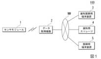
図1は、本発明の実施形態の口腔内センシングシステムの一例を示す図である。本発明の実施形態の口腔内センシングシステム100は、口腔内に設置されたセンサモジュールで生体情報をセンシングする。
口腔内センシングシステム100は、センサモジュール1と、データ取得機器2と、歯科医師用端末装置3と、歯科用ストレージ4と、医師用端末装置5とを備える。
センサモジュール1とデータ取得機器2との間は、無線によって接続される。データ取得機器2と、歯科医師用端末装置3と、歯科用ストレージ4と、医師用端末装置5と、端末装置10とは、ネットワークNWを介して通信する。ネットワークNWは、例えば、インターネット、WAN(Wide Area Network)、LAN(Local Area Network)、プロバイダ装置、無線基地局などを含む。 (Intraoral sensing system)
1 is a diagram showing an example of an intraoral sensing system according to an embodiment of the present invention. The
The
The
センサモジュール1は、患者PAの口腔内に装着され、生体情報をセンシングすることによって取得したデータと、そのデータを取得した日時情報とを関連付けて保存する。
データ取得機器2は、センサ情報を取得することを示すコマンドを作成し、作成したコマンドを、センサモジュール1へ送信する。
センサモジュール1は、データ取得機器2が送信したセンサ情報を取得することを示すコマンドを受信した場合に、記憶しているデータと日時情報と患者IDの識別情報(以下「患者ID」という)とを含むセンサ情報を作成し、作成したセンサ情報を、データ取得機器2へ送信する。
データ取得機器2は、送信したコマンドに対して、センサモジュール1が送信したセンサ情報を受信する。データ取得機器2は、受信したセンサ情報を、歯科医師用端末装置3と歯科用ストレージ4とのいずれか一方又は両方へ送信する。
歯科用ストレージ4は、データ取得機器2が送信したセンサ情報に含まれるデータと日時情報と患者IDとを関連付けて保存する。
歯科医師用端末装置3は、データ取得機器2が送信したセンサ情報に含まれるデータと日時情報と患者IDとを取得する。歯科医師用端末装置3は、取得したデータと日時情報とに基づいて、そのデータを解析する。 The
The
When the
In response to the transmitted command, the
The
The
また、歯科医師用端末装置3は、歯科医師などのユーザが、データを取得する操作を行うことによって、患者IDとデータを取得することを示す情報とを含み、歯科用ストレージ4を宛先とするセンサ情報要求を作成する。歯科医師用端末装置3は、作成したセンサ情報要求を、歯科用ストレージ4へ送信する。
歯科用ストレージ4は、歯科医師用端末装置3が送信したセンサ情報要求に含まれる患者IDとデータを取得することを示す情報とに基づいて、患者IDに関連付けて記憶されているデータと日時情報とを取得する。歯科用ストレージ4は、取得したデータと日時情報とを含む、センサ情報応答を作成する。歯科用ストレージ4は、作成したセンサ情報応答を、歯科医師用端末装置3へ送信する。
歯科医師用端末装置3は、歯科用ストレージ4へ送信したセンサ情報要求に対して、歯科用ストレージ4が送信したセンサ情報応答を受信する。歯科医師用端末装置3は、センサ情報応答に含まれるデータと日時情報とに基づいて、そのデータを解析する。つまり、歯科医師用端末装置3は、歯科用ストレージ4に保存されたデータを、患者ID毎に解析する。
また、医師用端末装置5は、疾患が発症した患者PAの患者IDに関連付けて記憶されているデータを、歯科医師用端末装置3へ要求する。医師用端末装置5は、医師などのユーザが、データを取得する操作を行うことによって、患者の氏名と疾患名と情報提供期間とを含み、歯科医師用端末装置3を宛先とするセンサ情報要求を作成する。医師用端末装置5は、作成したセンサ情報要求を、歯科医師用端末装置3へ送信する。
歯科医師用端末装置3は、医師用端末装置5が送信したセンサ情報要求を受信した場合に、そのセンサ情報要求に含まれる患者の氏名を患者IDに変更し、疾患名から生体情報を特定し、特定した生体情報を含む、歯科用ストレージ4を宛先とするセンサ情報要求を作成する。歯科医師用端末装置3は、作成したセンサ情報要求を、歯科用ストレージ4へ転送する。歯科医師用端末装置3は、歯科用ストレージ4へ転送したセンサ情報要求に対して、歯科用ストレージ4が送信したセンサ情報応答を受信する。歯科医師用端末装置3は、受信したセンサ情報応答に含まれる患者IDを該当する患者の氏名に変更し、センシングを開始する日時情報と測定の時間間隔を示す情報とに基づいて、各デジタルデータの測定日時を特定し、特定した測定日時を含む、医師用端末装置5を宛先とするセンサ情報応答を作成する。歯科医師用端末装置3は、作成したセンサ情報要求を、医師用端末装置5へ転送する。
医師用端末装置5は、歯科医師用端末装置3へ送信したセンサ情報要求に対して、歯科医師用端末装置3が送信したセンサ情報応答を受信する。医師用端末装置5は、センサ情報応答に含まれる患者の氏名と、疾患名と、デジタルデータと、測定日時を示す情報とを取得する。医師は、取得した疾患名と、デジタルデータと、測定日時を示す情報とに基づいて、疾病の治療を行う。 Furthermore, when a user such as a dentist performs an operation to acquire data, the
The
The
The
When the
The
以下、口腔内センシングシステム100に含まれるセンサモジュール1と、データ取得機器2と、歯科医師用端末装置3と、歯科用ストレージ4と、医師用端末装置5とについて詳細に説明する。
図2は、本実施形態の口腔内センシングシステムに含まれるセンサモジュールと、データ取得機器と、歯科医師用端末装置と、歯科用ストレージと、医師用端末装置との一例を示すブロック図である。 The
FIG. 2 is a block diagram showing an example of a sensor module, a data acquisition device, a dentist terminal device, a dental storage, and a doctor terminal device included in the intraoral sensing system of this embodiment.
(センサモジュール1)
センサモジュール1は、電池11と、センサ12と、センサモジュール部13とを備える。電池11、センサ12、センサモジュール部13などの回路ブロックは、薄い回路基板あるいはフレキシブル基板上に実装される。センサモジュール部13の一例は、信号処理部14と、メモリ15と、無線送受信部16とを含むチップで実現される。センサモジュール1は、矯正器具や義歯に取りけられたり、インプラントに埋め込まれたりする。
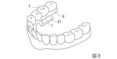
図3は、本実施形態の口腔内生体モニタリングシステムのセンサモジュールの外観の例1を示す図である。
図4は、本実施形態の口腔内生体モニタリングシステムのセンサモジュールが取り付けられた部分の断面の例1を示す図である。
図3、図4に示されるように、センサモジュール1は、マウスピース21によって保持される。マウスピース21の一例は、少なくとも一部が光を透過させる材料で作製されている。マウスピース21の一例は、被検体(患者PA)の歯冠T及び歯茎Gの少なくとも一方を覆う状態で、歯冠Tに装着される。また、マウスピース21の一例は、被検体の歯茎Gの少なくとも一部を覆っている。さらに、マウスピース21の一例は、センサモジュール1の少なくとも一部を覆っている。具体的には、マウスピース21は、センサモジュール1の少なくとも一部を封止している。図3に示される例では、センサモジュール1は、歯の内側に設置されている。
図5は、本実施形態の口腔内生体モニタリングシステムのセンサモジュールの外観の例2を示す図である。図5に示される例では、センサモジュール1は、歯の外側に設置されている。 (Sensor module 1)
The
FIG. 3 is a diagram showing a first example of the appearance of a sensor module of the intraoral biological monitoring system of this embodiment.
FIG. 4 is a diagram showing a first example of a cross section of a portion where a sensor module of the intra-oral biological monitoring system of this embodiment is attached.
As shown in Fig. 3 and Fig. 4, the
5 is a diagram showing a second example of the external appearance of the sensor module of the intra-oral biological monitoring system of the present embodiment. In the example shown in Fig. 5, the
図3から図5に示したように、センサモジュール1を歯列矯正器具に装着する場合、歯列矯正器具は、ポリエチレン系素材と、ポリウレタン系素材と、アクリル系レジンの熱可塑性高分子化合物とのいずれかなどを含んで構成される。歯列矯正器具は、型押し、3Dプリンタなどの成型技術を使用して、歯型、歯茎型形状に成形される。
歯列矯正器具の一部に窪みが形成され、形成された窪みに、センサモジュール1が設置される。センサモジュール1を設置する場所は、歯冠部側壁に相当する部分、歯茎に相当する部分のいずれでもよい。上歯と、下歯とのかみ合わせを考慮した場合には、図4に示したように、歯茎に相当する部分に、センサモジュール1を設置するのが望ましい。
また、光を使用した脈波を測定する脈波センサ、光を使用して血中酸素濃度を測定するパルスオキシメータ、光を使用して心拍を測定する心拍センサ、レーザー光を使って血流を測定するレーザーセンサの少なくとも一つを、センサモジュール1が搭載している場合には、センサモジュール1は、歯茎部分の血管から情報を取得するため、歯茎部分にセンサモジュール1を設置することが望ましい。
さらに、センサモジュール1が、光、レーザーを使用するセンサを搭載する場合には、光の透過が必須となるため、歯列矯正器具の少なくとも一部は、波長400nm~1000nmのいずれかの光の波長を透過することができる材料で構成される必要がある。 3 to 5, when the
A recess is formed in a part of the orthodontic appliance, and the
Furthermore, if the
Furthermore, when the
図6は、本実施形態の口腔内生体モニタリングシステムのセンサモジュールが取り付けられた部分の断面の例2を示す図である。図6に示される例では、センサモジュール1は、インプラントINに埋め込まれる。インプラントINは、インプラント体63を備えている。インプラント体63は、埋入の対象となる骨64の内部に埋め込まれるネジ部62と、ネジ部62に接続された頭部61とを備えている。
図6に示したように、センサモジュール1を、インプラントINに装着する場合、インプラント義歯などの頭部61の中に、センサモジュール1が設置される。頭部61の中に、センサモジュール1が設置され、且つセンサモジュール1に、光を使用して脈波を測定する脈波センサと、光を使用して血中酸素濃度を測定するパルスオキシメータと、光を使用して心拍を測定する心拍センサと、レーザー光を使用して血流を測定するレーザーセンサとのうち、少なくとも一つを、センサモジュール1が搭載している場合には、歯茎の血管から情報を取得するため、歯茎に相当する部分に、センサモジュール1を設置するのが望ましい。
さらに、センサモジュール1が、光、レーザーを使用するセンサを搭載する場合には、光の透過が必須のため、頭部61の少なくとも一部は、波長400nm~1000nmのいずれかの光の波長を透過することができる材料で構成される必要がある。図2に戻り説明を続ける。 Fig. 6 is a diagram showing a second example of a cross section of a portion where a sensor module of the intra-oral biological monitoring system of this embodiment is attached. In the example shown in Fig. 6, the
6, when the
Furthermore, when the
電池11の一例は、一次電池あるいは二次電池である。電池11は、センサ12と、センサモジュール部13とへ、電力を供給する。
センサ12は、温度センサと、加速度センサと、ジャイロセンサと、圧力センサと、歪センサと、脈波センサと、パルスオキシメータと、心拍センサと、レーザーセンサとのうち、少なくとも一つを含み、センシングすることによって、センシングデータを取得する。ここで、脈波センサは光を使って脈波を測定し、パルスオキシメータは光を使って血中酸素濃度を測定し、心拍センサは光を使って心拍を測定し、レーザーセンサはレーザー光を使って血流を測定する。
また、前述したように、センサモジュール1が、光を使用して脈波を測定する脈波センサと、光を使用して血中酸素濃度を測定するパルスオキシメータと、光を使用して心拍を測定する心拍センサと、レーザー光を使用して血流を測定するレーザーセンサとの少なくとも一つを含んで構成されてもよい。また、センサモジュール1が、光、レーザーを使用するセンサを含んで構成されてもよい。センサ12は、取得したセンシングデータを、センサモジュール部13へ出力する。ここで、センシングデータ(センサデータ)は、センサモジュール1に搭載されたセンサ12の出力値である。例えば、センサモジュール1に、温度センサと加速度センサとが搭載されている場合は、温度センサと加速度センサとが、温度センサ値と加速度センサ値(x,y,z)を、それぞれ測定間隔毎に出力する。 An example of the
The
As described above, the
無線送受信部16は、データ取得機器2との間で通信を行う。無線送受信部16と、データ取得機器2との間での通信に使用される無線通信方式の一例は、Bluetooth Low Energy(BLE)である。ただし、BLE以外の通信方式で、無線送受信部16と、データ取得機器2との間で無線通信が行われてもよい。
具体的には、無線送受信部16は、データ取得機器2が送信した初期設定情報を受信する。初期設定情報には、センサモジュール1がセンシングを開始する日時情報と、測定の時間間隔を示す情報と、患者IDとが含まれる。ここで、日時情報には、年と月とを示す情報が含まれてもよい。
また、無線送受信部16は、データ取得機器2が送信したコマンドを受信する。無線送受信部16は、信号処理部14が出力したセンサ情報を取得し、取得したセンサ情報を、口腔外部のデータ取得機器2へ送信する。
信号処理部14は、マイコンと、アナログ-デジタル変換回路 (ADC: analog to digital converter)とを含んで構成される。信号処理部14は、無線送受信部16が受信した初期設定情報を取得し、取得した初期設定情報に含まれるセンシングを開始する日時情報と、測定の時間間隔を示す情報と、患者IDとを取得する。信号処理部14は、取得したセンシングを開始する日時情報と、測定の時間間隔を示す情報と、患者IDとを、メモリ15に記憶する。また、信号処理部14は、取得した測定の時間間隔を示す情報を、センサ12へ設定する。
信号処理部14は、センサ12が出力したセンシングデータを取得し、取得したセンシングデータをデジタルデータへ変換する。信号処理部14は、センシングデータを変換することによって得られたデジタルデータと、測定インデックスとを関連付けて、メモリ15に記憶する。ここで、測定インデックスは、デジタルデータの識別情報である。測定インデックスとセンサデータは測定間隔毎に保存される。測定インデックスの一例は、測定順に割り振られた一意に決まる数値である。 The
Specifically, the
Furthermore, the
The
The
信号処理部14は、無線送受信部16が受信したコマンドを取得し、取得したコマンドを解釈する。信号処理部14は、コマンドを解釈した結果に基づいて、メモリ15と、無線送受信部16とを制御する。具体的には、信号処理部14は、無線送受信部16が受信したコマンドが、センサ情報を取得することである場合に、メモリ15に記憶されたセンシングを開始する日時情報と、測定の時間間隔を示す情報と、患者IDと、センサモジュール1のID(センサ12のID)と、測定インデックスと、デジタルデータとを関連付けた情報を含み、データ取得機器2を宛先とするセンサ情報を作成する。ここで、センサモジュール1のIDは、センサモジュール1の識別情報である。信号処理部14は、作成したセンサ情報を、無線送受信部16へ出力する。The
(データ取得機器2)
データ取得機器2は、パーソナルコンピュータ、サーバ、スマートフォン、タブレットコンピュータ又は産業用コンピュータ等の装置によって実現される。データ取得機器2は、例えば、第1通信部21-1と、第2通信部21-2と、処理部22と、記憶部25とを備える。
第1通信部21-1は、通信モジュールによって実現される。第1通信部21-1は、外部の通信装置と通信する。第1通信部21-1は、BLEなどの通信方式で通信してもよい。第1通信部21-1は、センサモジュール1と通信するために必要な通信情報を保持する。第1通信部21-1は、センサモジュール1へ、処理部22が出力した初期設定情報を送信する。第1通信部21-1は、センサモジュール1へ、処理部22が出力したコマンドを送信する。第1通信部21-1は、送信したコマンドに対して、センサモジュール1が送信したセンサ情報を受信する。
第2通信部21-2は、通信モジュールによって実現される。第2通信部21-2は、ネットワークNWを介して、外部の通信装置と通信する。第2通信部21-2は、例えば有線LANなどの通信方式で通信してもよい。第2通信部21-2は、ネットワークNWを介して歯科医師用端末装置3、及び歯科用ストレージ4と通信するために必要な通信情報を保持する。第2通信部21-2は、歯科医師用端末装置3が送信したセンサ情報取得要求を受信する。第2通信部21-2は、処理部22が出力したセンサ情報を、歯科医師用端末装置3へ送信する。第2通信部21-2は、処理部22が出力したセンサ情報を、歯科用ストレージ4へ送信する。 (Data acquisition device 2)
The
The first communication unit 21-1 is realized by a communication module. The first communication unit 21-1 communicates with an external communication device. The first communication unit 21-1 may communicate using a communication method such as BLE. The first communication unit 21-1 holds communication information necessary for communicating with the
The second communication unit 21-2 is realized by a communication module. The second communication unit 21-2 communicates with an external communication device via the network NW. The second communication unit 21-2 may communicate using a communication method such as a wired LAN. The second communication unit 21-2 holds communication information required to communicate with the
記憶部25は、HDD(Hard Disk Drive)やフラッシュメモリ、RAM(Random Access Memory)、ROM(Read Only Memory)などにより実現される。
処理部22は、例えば、CPUなどのハードウェアプロセッサが記憶部25に格納されたコンピュータプログラム(ソフトウェア)を実行することにより実現される。また、これらの機能部のうち一部または全部は、LSI(Large Scale Integration)やASIC(Application Specific Integrated Circuit)、FPGA(Field-Programmable Gate Array)、GPU(Graphics Processing Unit)などのハードウェア(回路部;circuitryを含む)によって実現されてもよいし、ソフトウェアとハードウェアとの協働によって実現されてもよい。コンピュータプログラムは、予めHDD(Hard Disk Drive)やフラッシュメモリなどの記憶装置に格納されていてもよいし、DVDやCD-ROMなどの着脱可能な記憶媒体に格納されており、記憶媒体がドライブ装置に装着されることでインストールされてもよい。
処理部22は、センシングを開始する日時情報と、測定の時間間隔を示す情報と、患者IDとを含む初期設定情報を作成する。処理部22は、センサモジュール1が起動し、センサモジュール1が起動したことを検出した場合に、初期設定情報を作成する。処理部22は、作成した初期設定情報を、第1通信部21-1へ出力する。処理部22は、第2通信部21-2が受信したセンサ情報取得要求を取得する。処理部22は、取得したセンサ情報取得要求に基づいて、センサ情報を取得するコマンドを作成する。処理部22は、作成したコマンドを、第1通信部21-1へ出力する。処理部22は、第1通信部21-1が受信したセンサ情報を取得する。処理部22は、取得したセンサ情報を、第2通信部21-2へ出力する。 The
The
The
(歯科医師用端末装置3)
歯科医師用端末装置3は、パーソナルコンピュータ、サーバ、スマートフォン、タブレットコンピュータ又は産業用コンピュータ等の装置によって実現される。歯科医師用端末装置3は、歯科医院などの歯の検査や治療を行う医院に設置される。歯科医師用端末装置3は、例えば、通信部31と、処理部32と、操作部33と、記憶部35とを備える。
通信部31は、通信モジュールによって実現される。通信部31は、ネットワークNWを介して、外部の通信装置と通信する。通信部31は、例えば有線LANなどの通信方式で通信してもよい。通信部31は、ネットワークNWを介して、データ取得機器2、歯科用ストレージ4、及び医師用端末装置5と通信するために必要な通信情報を保持する。
具体的には、通信部31は、処理部32が出力したセンサ情報取得要求を、データ取得機器2へ送信し、送信したセンサ情報取得要求に対して、データ取得機器2が送信したセンサ情報を受信する。通信部31は、処理部32が出力したセンサ情報要求を、歯科用ストレージ4へ送信し、送信したセンサ情報要求に対して、歯科用ストレージ4が送信したセンサ情報応答を受信する。
通信部31は、医師用端末装置5が送信したセンサ情報要求を受信し、受信したセンサ情報要求に対して、処理部32が出力したセンサ情報要求を、歯科用ストレージ4へ送信する。通信部31は、歯科用ストレージ4が送信したセンサ情報応答を受信し、受信したセンサ情報応答に対して、処理部32が出力したセンサ情報応答を、医師用端末装置5へ送信する。
操作部33は、入力デバイスを備え、歯科医師の操作を受け付ける。この入力デバイスには、キーボード等の文字情報を入力するデバイス、マウス、タッチパネル等のポインティングデバイス、釦、ダイヤル、ジョイスティック、タッチセンサ、タッチパッド等が含まれる。歯科医師は、操作部33を操作することによって、センサ情報を取得することを要求する情報と、患者IDとのいずれか一方又は両方を入力する。 (Dentist terminal device 3)
The
The
Specifically, the
The
The operation unit 33 includes an input device and accepts operations by a dentist. The input device includes a device for inputting character information such as a keyboard, a pointing device such as a mouse or a touch panel, a button, a dial, a joystick, a touch sensor, a touch pad, etc. The dentist operates the operation unit 33 to input either or both of information requesting acquisition of sensor information and a patient ID.
記憶部35は、HDDやフラッシュメモリ、RAM、ROMなどにより実現される。
処理部32は、例えば、CPUなどのハードウェアプロセッサが記憶部35に格納されたコンピュータプログラム(ソフトウェア)を実行することにより実現される。また、これらの機能部のうち一部または全部は、LSIやASIC、FPGA、GPUなどのハードウェア(回路部;circuitryを含む)によって実現されてもよいし、ソフトウェアとハードウェアとの協働によって実現されてもよい。コンピュータプログラムは、予めHDDやフラッシュメモリなどの記憶装置に格納されていてもよいし、DVDやCD-ROMなどの着脱可能な記憶媒体に格納されており、記憶媒体がドライブ装置に装着されることでインストールされてもよい。 The
The
処理部32は、歯科医師などのユーザが操作部33を操作することによって、操作部33が出力したセンサ情報を取得することを要求する情報に基づいて、センサ情報取得要求を作成し、作成したセンサ情報取得要求を、通信部31へ出力する。処理部32は、センサ情報取得要求に対して、データ取得機器2が送信したセンサ情報を、通信部31から取得する。処理部32は、取得したセンサ情報に含まれるセンシングを開始する日時情報と、測定の時間間隔を示す情報と、患者IDと、センサモジュール1のIDと、測定インデックスと、デジタルデータとを取得する。処理部32は、取得したデジタルデータから、患者PAの歯科治療に必要なデジタルデータを抽出する。処理部32は、抽出したデジタルデータと、抽出したデジタルデータに関連付けられるセンシングを開始する日時情報と、測定の時間間隔を示す情報とに基づいて、歯科治療に必要な解析を行う。
また、処理部32は、歯科医師などのユーザが操作部33を操作することによって、操作部33が出力したセンサ情報を取得することを要求する情報と、患者IDとに基づいて、センサ情報を要求する患者IDと、センサ情報を要求するための情報とを含み、歯科用ストレージ4を宛先とするセンサ情報要求を作成する。処理部32は、作成したセンサ情報要求を、通信部31へ出力する。処理部32は、センサ情報要求に対して、歯科用ストレージ4が送信したセンサ情報応答を、通信部31から取得する。処理部32は、取得したセンサ情報応答に含まれるセンシングを開始する日時情報と、測定の時間間隔を示す情報と、患者IDと、センサモジュール1のIDと、測定インデックスと、デジタルデータとを取得する。処理部32は、取得したデジタルデータから、患者PAの歯科治療に必要なデジタルデータを抽出する。処理部32は、抽出したデジタルデータと、抽出したデジタルデータに関連付けられるセンシングを開始する日時情報と、測定の時間間隔を示す情報とに基づいて、歯科治療に必要な解析を行う。 The
In addition, the
また、処理部32は、通信部31から、医師用端末装置5が送信したセンサ情報要求を取得し、取得したセンサ情報要求に含まれる患者の氏名を該当する患者IDに変更し、疾患名から生体情報を特定し、特定した生体情報を含む、歯科用ストレージ4を宛先とするセンサ情報要求を、通信部31へ出力する。例えば、歯科医師用端末装置3は、疾患名とその疾患に関係するセンサデータとを関連付けたデータベースが構築されている。処理部32は、センサ情報要求に含まれる疾患名を取得し、取得した疾患名に関連付けられるセンサデータを取得する。
具体的には、処理部32は、センサ情報要求から疾患名Aを取得し、取得した疾患名Aに関連付けられている温度センサデータを特定できる。処理部32は、センサ情報要求から疾患名Bを取得し、取得した疾患名Bに関連付けられる温度センサデータと加速度センサデータとを特定できる。このように構成することによって、歯科医師それぞれの判断で情報が提供されることをなくすことができる。つまり、歯科医師によって提供されるデータが異なるという不具合はなくなる。処理部32は、このセンサ情報要求に対して、歯科用ストレージ4が送信したセンサ情報応答を、通信部31から取得する。処理部32は、取得したセンサ情報応答に含まれる患者IDを該当する患者の氏名に変更し、センシングを開始する日時情報と測定の時間間隔を示す情報とに基づいて、各デジタルデータの測定日時を特定し、特定した測定日時を含む、医師用端末装置5を宛先とするセンサ情報応答を、通信部31へ出力する。 The
Specifically, the
(歯科用ストレージ4)
歯科用ストレージ4は、パーソナルコンピュータ、サーバ、又は産業用コンピュータ等の装置によって実現される。歯科用ストレージ4の一例は、歯科医院などの歯の検査や治療を行う医院に設置される。また、歯科用ストレージ4が、クラウド上で実現されてもよい。歯科用ストレージ4は、例えば、通信部41と、処理部42と、記憶部45とを備える。
通信部41は、通信モジュールによって実現される。通信部41は、ネットワークNWを介して、外部の通信装置と通信する。通信部41は、例えば有線LANなどの通信方式で通信してもよい。通信部41は、ネットワークNWを介して、データ取得機器2、及び歯科用ストレージ4と通信するために必要な通信情報を保持する。具体的には、通信部41は、データ取得機器2が送信したセンサ情報を受信する。通信部41は、歯科医師用端末装置3が送信したセンサ情報要求を受信し、受信したセンサ情報要求に対して、処理部42が出力したセンサ情報応答を、歯科医師用端末装置3へ送信する。 (Dental Storage 4)
The
The communication unit 41 is realized by a communication module. The communication unit 41 communicates with an external communication device via the network NW. The communication unit 41 may communicate using a communication method such as a wired LAN. The communication unit 41 holds communication information required to communicate with the
記憶部45は、HDDやフラッシュメモリ、RAM、ROMなどにより実現される。
処理部42は、例えば、CPUなどのハードウェアプロセッサが記憶部45に格納されたコンピュータプログラム(ソフトウェア)を実行することにより実現される。また、これらの機能部のうち一部または全部は、LSIやASIC、FPGA、GPUなどのハードウェア(回路部;circuitryを含む)によって実現されてもよいし、ソフトウェアとハードウェアとの協働によって実現されてもよい。コンピュータプログラムは、予めHDDやフラッシュメモリなどの記憶装置に格納されていてもよいし、DVDやCD-ROMなどの着脱可能な記憶媒体に格納されており、記憶媒体がドライブ装置に装着されることでインストールされてもよい。 The
The
処理部42は、通信部41が受信したセンサ情報を取得し、取得したセンサ情報に含まれるセンシングを開始する日時情報と、測定の時間間隔を示す情報と、患者IDと、センサモジュール1のIDと、測定インデックスと、デジタルデータとを取得する。処理部42は、取得したセンシングを開始する日時情報と、測定の時間間隔を示す情報と、患者IDと、センサモジュール1のIDと、測定インデックスと、デジタルデータとを関連付けて、記憶部45に記憶する。
また、処理部42は、通信部41が受信したセンサ情報要求を取得し、取得したセンサ情報要求に含まれるセンサ情報を要求する患者IDと、センサ情報を要求するための情報とを取得する。処理部42は、取得した患者IDに関連付けて記憶されているセンシングを開始する日時情報と、測定の時間間隔を示す情報と、センサモジュール1のIDと、測定インデックスと、デジタルデータとを、取得する。歯科用ストレージ4は、患者IDと、取得したセンシングを開始する日時情報と、測定の時間間隔を示す情報と、センサモジュール1のIDと、測定インデックスと、デジタルデータとを含み、歯科医師用端末装置3を宛先とするセンサ情報応答を作成する。歯科用ストレージ4は、作成したセンサ情報応答を、歯科医師用端末装置3へ送信する。 The
The
(医師用端末装置5)
医師用端末装置5は、パーソナルコンピュータ、サーバ、スマートフォン、タブレットコンピュータ又は産業用コンピュータ等の装置によって実現される。医科医院などの疾患の治療を行う医院に設置される。医師用端末装置5は、例えば、通信部51と、処理部52と、操作部53と、記憶部55とを備える。
通信部51は、通信モジュールによって実現される。通信部51は、ネットワークNWを介して、外部の通信装置と通信する。通信部51は、例えば有線LANなどの通信方式で通信してもよい。通信部51は、ネットワークNWを介して、歯科医師用端末装置3と通信するために必要な通信情報を保持する。具体的には、通信部51は、処理部52が出力したセンサ情報要求を、歯科医師用端末装置3へ送信し、歯科医師用端末装置3が送信したセンサ情報応答を受信する。
操作部53は、入力デバイスを備え、医師などのユーザの操作を受け付ける。この入力デバイスには、キーボード等の文字情報を入力するデバイス、マウス、タッチパネル等のポインティングデバイス、釦、ダイヤル、ジョイスティック、タッチセンサ、タッチパッド等が含まれる。医師は、操作部53を操作することによって、センサ情報を取得することを要求する情報と、患者IDとを入力する。 (Doctor's terminal device 5)
The
The
The
記憶部55は、HDDやフラッシュメモリ、RAM、ROMなどにより実現される。
処理部52は、例えば、CPUなどのハードウェアプロセッサが記憶部55に格納されたコンピュータプログラム(ソフトウェア)を実行することにより実現される。また、これらの機能部のうち一部または全部は、LSIやASIC、FPGA、GPUなどのハードウェア(回路部;circuitryを含む)によって実現されてもよいし、ソフトウェアとハードウェアとの協働によって実現されてもよい。コンピュータプログラムは、予めHDDやフラッシュメモリなどの記憶装置に格納されていてもよいし、DVDやCD-ROMなどの着脱可能な記憶媒体に格納されており、記憶媒体がドライブ装置に装着されることでインストールされてもよい。
処理部52は、医師などのユーザが操作部53を操作することによって、操作部53が出力した疾患名と、患者の氏名とを取得する。処理部52は、取得したセンサ情報を要求する患者の氏名と、疾患名とを含み、歯科医師用端末装置3を宛先とするセンサ情報要求を作成する。処理部52は、作成したセンサ情報要求を、通信部51へ出力する。処理部52は、センサ情報要求に対して、歯科医師用端末装置3が送信したセンサ情報応答を、通信部51から取得する。処理部52は、取得したセンサ情報応答に含まれる患者の氏名と、疾患名と、デジタルデータと、測定日時を示す情報とを取得する。処理部52は、取得した疾患名と、デジタルデータと、測定日時を示す情報とに基づいて、疾病の治療を行う。 The
The processing unit 52 is realized, for example, by a hardware processor such as a CPU executing a computer program (software) stored in the
The processing unit 52 acquires the disease name and the patient's name output by the
次に、口腔内センシングシステム100の動作について説明する。
(口腔内センシングシステム100の動作)
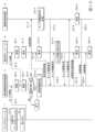
図7は、本実施形態の口腔内センシングシステムの動作の例1を示すフロー図である。
(ステップS1-1)
患者PAは、センサモジュール1を装着する。
(ステップS2-1)
データ取得機器2は、センシングを開始する日時情報と、測定の時間間隔を示す情報と、患者IDとを含む初期設定情報を作成する。データ取得機器2は、作成した初期設定情報を、センサモジュール1へ送信する。
センサモジュール1は、データ取得機器2が送信した初期設定情報を受信する。センサモジュール1は、受信した初期設定情報に含まれるセンシングを開始する日時情報と、測定の時間間隔を示す情報と、患者IDとを取得する。信号処理部14は、取得したセンシングを開始する日時情報と、測定の時間間隔を示す情報と、患者IDとを、メモリ15に記憶する。また、信号処理部14は、取得した測定の時間間隔を示す情報を、センサ12へ設定する。
センサ12は、測定の時間間隔に該当する周期で、センシングデータを取得する。センサ12は、取得したセンシングデータを、センサモジュール部13へ出力する。信号処理部14は、センサ12が出力したセンシングデータを取得し、取得したセンシングデータをデジタルデータへ変換する。信号処理部14は、センシングデータを変換することによって得られたデジタルデータと、測定インデックスとを関連付けて、メモリ15に記憶する。センサモジュール1は、15日間から30日間などの所定に期間の間、日常生活内のデジタルデータと、測定インデックスとを関連付けて、メモリ15に記憶する。
(ステップS3-1)
所定の期間が経過した後に、患者PAは、歯科医院に来院する。歯科医師は、センサモジュール1を取り出す。
歯科医師用端末装置3は、歯科医師などのユーザの操作に基づいて、センサ情報取得要求を作成し、作成したセンサ情報取得要求を、データ取得機器2へ送信する。
データ取得機器2は、歯科医師用端末装置3が送信したセンサ情報取得要求を受信し、受信したセンサ情報取得要求に基づいて、センサ情報を取得することを示すコマンドを作成し、作成したコマンドを、センサモジュール1へ送信する。
センサモジュール1において、無線送受信部16は、データ取得機器2が送信したコマンドを受信する。信号処理部14は、無線送受信部16が受信したコマンドを取得し、取得したコマンドが、センサ情報を取得することである場合に、メモリ15に記憶されたセンシングを開始する日時情報と、測定の時間間隔を示す情報と、患者IDと、センサモジュール1のIDと、測定インデックスと、デジタルデータとを関連付けた情報を含み、データ取得機器2を宛先とするセンサ情報を作成する。信号処理部14は、作成したセンサ情報を、無線送受信部16へ出力する。無線送受信部16は、信号処理部14が出力したセンサ情報を取得し、取得したセンサ情報を、データ取得機器2へ送信する。データ取得機器2は、センサモジュール1が送信したセンサ情報を受信する。 Next, the operation of the
(Operation of intraoral sensing system 100)
FIG. 7 is a flow diagram showing example 1 of the operation of the intraoral sensing system of this embodiment.
(Step S1-1)
The patient PA wears the
(Step S2-1)
The
The
The
(Step S3-1)
After a predetermined period of time has passed, the patient PA visits a dental clinic. The dentist takes out the
The
The
In the
(ステップS4-1)
歯科医師用端末装置3は、歯科医師などのユーザの操作に基づいて、センサ情報要求を作成し、作成したセンサ情報要求を、データ取得機器2へ送信する。
データ取得機器2は、歯科医師用端末装置3が送信したセンサ情報要求に基づいて、センサ情報応答を作成する。データ取得機器2は、作成したセンサ情報応答を、歯科医師用端末装置3へ送信する。
歯科医師用端末装置3は、センサ情報要求に対して、データ取得機器2が送信したセンサ情報応答を受信する。歯科医師用端末装置3は、受信したセンサ情報応答に含まれるセンシングを開始する日時情報と、測定の時間間隔を示す情報と、患者IDと、センサモジュール1のIDと、測定インデックスと、デジタルデータとを取得する。歯科医師用端末装置3は、取得したデジタルデータから、患者PAの歯科治療に必要なデジタルデータを抽出する。歯科医師用端末装置3は、抽出したデジタルデータと、抽出したデジタルデータに関連付けられるセンシングを開始する日時情報と、測定の時間間隔を示す情報とに基づいて、歯科治療に必要な解析を行う。例えば、歯科医師用端末装置3は、温度情報から患者PAが矯正器具を装着した時間を割り出したり、加速度情報から患者PAの咀嚼回数を割り出したりする。その後、ステップS1-1へ移行する。
歯科医師用端末装置3が解析した結果から、歯科医師は次の15日間~30日間などの所定の期間の治療計画を立案する。患者PAは、再度口腔内にセンサモジュール1を装着し、15日間~30日間などの所定の期間の日常生活内のデジタルデータを取得する。以降、これを繰り返す。
(ステップS5-1)
データ取得機器2は、受信したセンサ情報を、歯科用ストレージ4へ記憶する。
(ステップS6-1)
患者PAに疾患が発症する。
(ステップS7-1)
患者PAが医科医院MCを受診する。
(ステップS8-1)
医師は、患者PAの疾患の発症前までの生体情報が必要であるか否かを判断する。生体情報が必要でないと判断した場合、終了する。 (Step S4-1)
The
The
The
Based on the analysis results by the
(Step S5-1)
The
(Step S6-1)
Patient PA develops a disease.
(Step S7-1)
A patient PA visits a medical clinic MC.
(Step S8-1)
The doctor judges whether or not vital information of the patient PA before the onset of the disease is necessary. If it is judged that vital information is not necessary, the process ends.
(ステップS9-1)
医師は、患者PAの疾患の発症前までの生体情報が必要であると判断した場合に、歯科医院に生体情報の提供を依頼する。具体的には、医師などのユーザの操作に基づいて、医師用端末装置5は、患者の氏名と、疾患名とを含み、歯科医師用端末装置3を宛先とするセンサ情報要求を作成し、作成したセンサ情報要求を、歯科医師用端末装置3へ送信する。
(ステップS10-1)
歯科医師用端末装置3は、医師用端末装置5が送信したセンサ情報要求を受信し、受信したセンサ情報要求に含まれる患者の氏名を該当する患者IDに変更し、疾患名から生体情報を特定し、特定した生体情報を含む、歯科用ストレージ4を宛先とするセンサ情報要求を、歯科用ストレージ4へ転送する。
歯科用ストレージ4は、歯科医師用端末装置3が転送したセンサ情報要求を受信し、受信したセンサ情報要求に含まれる患者IDと生体情報とに基づいて、患者IDに関連付けて記憶されているセンシングを開始する日時情報と、測定の時間間隔を示す情報と、デジタルデータとを取得する。歯科用ストレージ4は、患者IDと、取得したセンシングを開始する日時情報と、測定の時間間隔を示す情報と、デジタルデータとを含む、歯科医師用端末装置3を宛先とするセンサ情報応答を作成する。歯科用ストレージ4は、作成したセンサ情報応答を、歯科医師用端末装置3へ送信する。
歯科医師用端末装置3は、歯科用ストレージ4が送信したセンサ情報応答を受信する。歯科医師用端末装置3は、受信したセンサ情報応答に含まれる患者IDを該当する患者の氏名に変更し、センシングを開始する日時情報と測定の時間間隔を示す情報とに基づいて、各デジタルデータの測定日時を特定し、特定した測定日時を含む、医師用端末装置5を宛先とするセンサ情報応答を、医師用端末装置5へ転送する。
(ステップS11-1)
医師用端末装置5は、歯科医師用端末装置3が転送したセンサ情報応答を受信する。医師用端末装置5は、受信したセンサ情報応答に含まれる患者の氏名と、疾患名と、デジタルデータと、測定日時を示す情報とを取得する。医師は、取得した疾患名と、デジタルデータと、測定日時を示す情報とに基づいて、疾病の治療を行う。 (Step S9-1)
When the doctor judges that the biological information of the patient PA before the onset of the disease is necessary, the doctor requests the dental clinic to provide the biological information. Specifically, based on the operation of the user such as the doctor, the
(Step S10-1)
The dentist's
The
The
(Step S11-1)
The
一例として、歯列矯正器具にセンサモジュール1を設置した場合について説明する。
治療が開始されると、歯科医師は、先ず患者PAの歯の初期位置を計測し、歯列矯正設計システムで、最終の歯の位置を計算する。歯列矯正設計システムで、歯の初期位置と最終の歯の位置から治療計画が計算され、最初の歯列矯正器具作製データが作られる。ここで、最初の歯列矯正器具作製データは、必ずしも一つではなく、複数の歯列矯正器具作製データが作成されてもよい。作成された歯列矯正器具作製データは、歯列矯正器具作製システムに送信され、歯列矯正器具作製システムで、歯列矯正器具が作製される。
患者PAは、作製された歯列矯正器具を装着する。患者PAが歯列矯正器具を装着することによって、治療が開始される。患者PAは、歯科医師が指示する装着時間などの所定の期間に従って歯列矯正器具を装着する。ここで、患者PAが、子供などである場合には、歯科医師が指示する装着時間などの所定の期間以下の装着時間である場合がある。
患者PAは、定期的に歯科医師の元を訪れ、歯列の状況の確認を依頼する。歯科医師は、患者PAから提出された歯列矯正器具に設置されたセンサモジュール1を、データ取得機器2と接続する。データ取得機器2は、センサモジュール1に保存されているセンサ情報を取得する。取り出されたセンサ情報に基づいて、患者PA固有の装着傾向が計算される。装着傾向の計算結果に、歯科医師がチェックした歯列状況を加味され、歯列矯正設計システムは、治療計画データを再計算する。再計算されたデータに基づいて、歯列矯正器具の三次元データが作成される。歯列矯正設計システムは、作成した三次元データを、歯列矯正器具作製システムへ転送する。
歯列矯正器具作成システムは、歯列矯正設計システムが送信した三次元データを受信する。歯列矯正器具作成システムは、受信した三次元データに基づいて、次の歯列矯正器具を作成する。歯列矯正器具システムが作成した次の歯列矯正器具を使用して、治療が再開される。
以降、患者PAは、定期的に歯科医師の元を訪れ、前述した手順が繰り返される。歯の位置が最終位置に達したところで治療が終了する。 As an example, a case where the
When treatment begins, the dentist first measures the initial positions of the teeth of the patient PA, and calculates the final tooth positions in the orthodontic design system. In the orthodontic design system, a treatment plan is calculated from the initial and final tooth positions, and initial orthodontic appliance manufacturing data is created. Here, the initial orthodontic appliance manufacturing data is not necessarily one piece, and multiple pieces of orthodontic appliance manufacturing data may be created. The created orthodontic appliance manufacturing data is sent to the orthodontic appliance manufacturing system, and the orthodontic appliance is manufactured in the orthodontic appliance manufacturing system.
The patient PA wears the prepared orthodontic appliance. Treatment begins when the patient PA wears the orthodontic appliance. The patient PA wears the orthodontic appliance for a predetermined period of time, such as a wearing time, instructed by a dentist. Here, if the patient PA is a child, the wearing time may be shorter than the predetermined period of time, such as a wearing time, instructed by a dentist.
The patient PA periodically visits the dentist and requests that the condition of his/her teeth be checked. The dentist connects the
The orthodontic appliance creation system receives the three-dimensional data sent by the orthodontic design system. The orthodontic appliance creation system creates a next orthodontic appliance based on the received three-dimensional data. Treatment is resumed using the next orthodontic appliance created by the orthodontic appliance system.
After that, the patient PA periodically visits the dentist and the above-mentioned procedure is repeated. When the teeth reach their final positions, the treatment is completed.
次に、口腔内センシングシステム100を利用している患者PAが、疾患を発症して医科医院を受診した場合について説明する。
医師は、患者PAが、疾患を発症するまでの体温、運動量、血流、心拍、血中酸素濃度、細菌などの日常の生体情報が必要と判断する。医師は、歯科医院に、患者PAの生体情報の転送を依頼する。ここで、生体情報は、医師が必要と判断した生体情報である。患者PAの生体情報の転送の依頼を受けた歯科医師は、歯科医師用端末装置3を操作することによって、歯科用ストレージ4から、医師が必要としている患者PAの生体情報を取得し、取得した生体情報を、医師用端末装置5へ転送する。
医師用端末装置5は、歯科医師用端末装置3が転送した生体情報を受信する。生体情報を受け取った医師は、患者PAの生体情報の経時変化に基づいて、治療計画や治療方法を策定する。 Next, a case will be described in which a patient PA using the
The doctor determines that daily biological information of the patient PA, such as body temperature, amount of exercise, blood flow, heart rate, blood oxygen concentration, bacteria, etc., is required before the onset of a disease. The doctor requests the dental clinic to transfer the biological information of the patient PA. Here, the biological information is the biological information that the doctor determines is necessary. Upon receiving the request to transfer the biological information of the patient PA, the dentist operates the
The
図7に示されるフロー図では、患者PAが受診した医科病院で、医師によって、発症前までの生体情報が必要であると判断される場合について説明したが、この例に限られない。例えば、歯科病院で、センサ情報応答から取得されたデジタルデータから、患者PAの疾患の治療に必要なデジタルデータが抽出され、抽出されたデジタルデータと、抽出したデジタルデータに関連付けられるセンシングを開始する日時情報と、測定の時間間隔を示す情報とを使用して解析が行われ、患者PAに疾患の疑いがあるか否かが判断されてもよい。さらに、患者PAに、疾患の疑いがある場合に、歯科病院から、医科病院へ、患者PAに、疾患の疑いがあることが連絡されてもよい。この場合の処理の一例について説明する。In the flow diagram shown in FIG. 7, a case is described in which a doctor at a medical hospital where the patient PA visits determines that biometric information from before the onset of symptoms is necessary, but this example is not limited to this. For example, at a dental hospital, digital data necessary for treating the patient PA's disease is extracted from the digital data acquired from the sensor information response, and the extracted digital data, date and time information for starting sensing associated with the extracted digital data, and information indicating the time interval of measurement are used to analyze whether the patient PA is suspected of having a disease. Furthermore, if the patient PA is suspected of having a disease, the dental hospital may notify the medical hospital of the patient PA's suspicion of the disease. An example of the processing in this case will be described.
図8は、本実施形態の口腔内センシングシステムの動作の例2を示すフロー図である。
ステップS1-2からステップS3-2は、図7のステップS1-1からステップS3-1を適用できる。
図示されていないが、ステップS3-1の後に、図7のステップS4-1と同様の処理が行われる。具体的には、歯科医師用端末装置3は、歯科医師などのユーザの操作に基づいて、センサ情報要求を作成し、作成したセンサ情報要求を、データ取得機器2へ送信する。データ取得機器2は、歯科医師用端末装置3が送信したセンサ情報要求に基づいて、センサ情報応答を作成する。データ取得機器2は、作成したセンサ情報応答を、歯科医師用端末装置3へ送信する。
歯科医師用端末装置3は、センサ情報要求に対して、データ取得機器2が送信したセンサ情報応答を受信する。歯科医師用端末装置3は、受信したセンサ情報応答に含まれるセンシングを開始する日時情報と、測定の時間間隔を示す情報と、患者IDと、センサモジュール1のIDと、測定インデックスと、デジタルデータとを取得する。歯科医師用端末装置3は、取得したデジタルデータから、患者PAの歯科治療に必要なデジタルデータを抽出する。歯科医師用端末装置3は、抽出したデジタルデータと、抽出したデジタルデータに関連付けられるセンシングを開始する日時情報と、測定の時間間隔を示す情報とに基づいて、歯科治療に必要な解析を行う。例えば、歯科医師用端末装置3は、温度情報から患者PAが矯正器具を装着した時間を割り出したり、加速度情報から患者PAの咀嚼回数を割り出したりする。その後、ステップS1-1へ移行する。
歯科医師用端末装置3が解析した結果から、歯科医師は次の15日間~30日間などの所定の期間の治療計画を立案する。患者PAは、再度口腔内にセンサモジュール1を装着し、15日間~30日間などの所定の期間の日常生活内のデジタルデータを取得する。以降、これを繰り返す。 (ステップS4-2)
データ取得機器2は、受信したセンサ情報を、歯科用ストレージ4へ記憶する。
(ステップS5-2)
歯科医師用端末装置3は、歯科医師などのユーザの操作に基づいて、センサ情報要求を作成し、作成したセンサ情報要求を、データ取得機器2へ送信する。
データ取得機器2は、歯科医師用端末装置3が送信したセンサ情報要求に基づいて、センサ情報応答を作成する。データ取得機器2は、作成したセンサ情報応答を、歯科医師用端末装置3へ送信する。
(ステップS6-2)
歯科医師用端末装置3は、センサ情報要求に対して、データ取得機器2が送信したセンサ情報応答を受信する。歯科医師用端末装置3は、受信したセンサ情報応答に含まれる患者IDと、センシングを開始する日時情報と、測定の時間間隔を示す情報と、センサモジュール1のIDと、測定インデックスと、デジタルデータとを取得する。歯科医師用端末装置3の処理部32は、取得したデジタルデータと、デジタルデータに関連付けられるセンシングを開始する日時情報と、測定の時間間隔を示す情報とを使用して解析を行う。処理部32は、解析結果に基づいて、疾患の疑いがあるか否かを判定する。疾患の疑いが無いと判定した場合には、処理を終了する。 FIG. 8 is a flow diagram showing a second example of the operation of the intraoral sensing system of this embodiment.
Steps S1-2 to S3-2 can be implemented by steps S1-1 to S3-1 in FIG.
7 is performed after step S3-1, although this is not shown in the figure. Specifically, the
The
Based on the analysis results by the dentist's
The
(Step S5-2)
The
The
(Step S6-2)
The
(ステップS7-2)
歯科医師用端末装置3において、処理部32は、疾患の疑いがあると判定した場合には、患者の氏名と、疑いがある疾患名とを含む、医師用端末装置5を宛先とする疾患情報を作成する。処理部32は、作成した疾患情報を、通信部31へ出力する。通信部31は、処理部32が出力した疾患情報を取得し、取得した疾患情報を、医師用端末装置5へ送信する。処理部32は、疾患情報を、医師用端末装置5へ通知した場合に、患者IDと、疑いがある疾患名と、疾患の発生日時と、通知した医科医院MCの名称とを関連付けて、歯科用ストレージ4に記憶させる。
(ステップS8-2)
医師用端末装置5は、歯科医師用端末装置3が送信した疾患情報を受信する。医科医院では、疾患情報に含まれる患者PAに受診を勧める連絡が行われる。
(ステップS9-2)
医科医院MCから、受診を勧められた患者PAは、医科医院MCを受信する。
ステップS10-2からステップS12-2は、図7のステップS9-1からステップS11-1を適用できる。
図8に示されるフローによれば、歯科医院DCは、患者PAの生体情報から、疾患の疑いがあるか否かを判定できる。このため、患者PAに、疾患が発病していない未病の段階で、歯科医師から、医師へ、患者PAに疾患が発病する可能性があることを通知できる。 (Step S7-2)
In the
(Step S8-2)
The
(Step S9-2)
A patient PA who has been recommended to visit a medical clinic MC receives the medical clinic MC.
Steps S9-1 to S11-1 in FIG. 7 can be applied to steps S10-2 to S12-2.
According to the flow shown in Fig. 8, the dental clinic DC can determine whether or not there is a suspicion of disease from the biological information of the patient PA. Therefore, the dentist can notify the doctor that the patient PA may develop a disease at the pre-disease stage.
また、例えば、歯科病院DCで、センサ情報応答から取得されたデジタルデータから、患者PAの疾患の治療に必要なデジタルデータが抽出され、抽出されたデジタルデータと、抽出したデジタルデータに関連付けられるセンシングを開始する日時情報と、測定の時間間隔を示す情報とを使用して解析が行われ、患者PAに、疾患の疑いがあるか否かが判断されてもよい。さらに、患者PAに疾患の疑いがある場合に、歯科病院DCから、患者PAへ、疾患の疑いがあることが連絡されてもよい。この場合の処理の一例について説明する。
図9は、本実施形態の口腔内センシングシステムの動作の例3を示すフロー図である。
ステップS1-3からステップS3-3は図7のステップS1-1からステップS3-1を適用でき、ステップS4-3からステップS6-3は、図8のステップS4-2からステップS6-2を適用できる。
(ステップS7-3)
歯科医院DCでは、処理部32が、疾患の疑いがあると判定した場合には、患者PAに、疾患の疑いがあることが通知される。
(ステップS8-3)
歯科医院DCから、疾患の疑いがあることを通知された患者PAは、医科医院MC受信する。
ステップS9-3からステップS11-3は、図7のステップS9-1からステップS11-1を適用できる。
図9に示されるフローによれば、歯科医院は、患者PAが生体情報から、疾患の疑いがあるか否かを判定できる。このため、患者PAに、疾患が発病していない未病の段階で、歯科医師から患者PAへ、疾患が発病する可能性があることを通知できる。 Also, for example, in the dental hospital DC, digital data necessary for treating the disease of the patient PA is extracted from the digital data acquired from the sensor information response, and analysis is performed using the extracted digital data, the date and time information of the start of sensing associated with the extracted digital data, and the information indicating the time interval of the measurement, to determine whether or not the patient PA is suspected of having a disease. Furthermore, if the patient PA is suspected of having a disease, the dental hospital DC may notify the patient PA of the suspicion of the disease. An example of the processing in this case will be described.
FIG. 9 is a flow diagram showing example 3 of the operation of the intraoral sensing system of this embodiment.
Steps S1-3 to S3-3 can be implemented by steps S1-1 to S3-1 in FIG. 7, and steps S4-3 to S6-3 can be implemented by steps S4-2 to S6-2 in FIG.
(Step S7-3)
At the dental clinic DC, if the
(Step S8-3)
A patient PA who has been notified by a dental clinic DC that he or she may have a disease receives the notification from a medical clinic MC.
Steps S9-3 to S11-3 can be implemented by steps S9-1 to S11-1 in FIG.
According to the flow shown in Fig. 9, the dental clinic can determine whether the patient PA is suspected of having a disease based on the biological information. Therefore, the dentist can notify the patient PA of the possibility of developing a disease at the pre-disease stage when the patient PA is not yet ill.
前述した実施形態では、センサモジュール1からデータ取得機器2へ、センサ情報が送信され、データ取得機器2から歯科医師用端末装置3と歯科用ストレージ4とのいずれか一方又は両方へ、センサ情報が送信される場合について説明したが、この例に限られない。例えば、センサモジュール1から歯科用ストレージ4へセンサ情報が送信されてもよい。このように構成することによって、データ取得機器2を使用することなく、歯科医師用端末装置3は、センサモジュール1に記憶されているセンサ情報を取得できる。この場合の処理の一例について説明する。
図10は、本実施形態の口腔内センシングシステムの動作の例4を示すフロー図である。図10は、センサモジュール1の初期設定が終了し、センサモジュール1が口腔内に装着された後の動作を示す。
ステップS1-4は、図7のステップS2-1を適用できる。
(ステップS2-4)
所定の期間が経過した後に、患者PAは、歯科医院DCに来院する。歯科医師は、センサモジュール1を取り出す。
歯科医師用端末装置3は、歯科医師などのユーザの操作に基づいて、センサ情報取得要求を作成し、作成したセンサ情報取得要求を、センサモジュール1へ送信する。
センサモジュール1において、無線送受信部16は、歯科医師用端末装置3が送信したセンサ情報取得要求を受信する。
(ステップS3-4)
センサモジュール1において、信号処理部14は、無線送受信部16が受信したセンサ情報取得要求を取得し、取得したセンサ情報取得要求に基づいて、メモリ15に記憶されたセンシングを開始する日時情報と、測定の時間間隔を示す情報と、患者IDと、センサモジュール1のIDと、測定インデックスと、デジタルデータとを関連付けた情報を含み、歯科医師用端末装置3を宛先とするセンサ情報を作成する。信号処理部14は、作成したセンサ情報を、無線送受信部16へ出力する。無線送受信部16は、信号処理部14が出力したセンサ情報を取得し、取得したセンサ情報を、歯科医師用端末装置3へ送信する。 In the above embodiment, a case has been described in which sensor information is transmitted from the
Fig. 10 is a flow diagram showing a fourth example of the operation of the intraoral sensing system of this embodiment. Fig. 10 shows the operation after the initial setting of the
Step S2-1 in FIG. 7 can be applied to step S1-4.
(Step S2-4)
After a predetermined period of time has passed, the patient PA visits the dental clinic DC. The dentist takes out the
The
In the
(Step S3-4)
In the
(ステップS4-4)
歯科医師用端末装置3は、センサモジュール1が送信したセンサ情報を受信する。
(ステップS5-4)
歯科医師用端末装置3は、受信したセンサ情報を、歯科用ストレージ4へ送信する。
(ステップS6-4)
歯科用ストレージ4は、歯科医師用端末装置3が送信したセンサ情報を受信する。
(ステップS7-4)
歯科用ストレージ4は、受信したセンサ情報に含まれるセンシングを開始する日時情報と、測定の時間間隔を示す情報と、患者IDと、センサモジュール1のIDと、測定インデックスと、デジタルデータとを関連付けて保存する。
(ステップS8-4)
歯科医師用端末装置3において、処理部32は、通信部31が受信したセンサ情報を取得し、取得したセンサ情報に含まれるセンシングを開始する日時情報と、測定の時間間隔を示す情報と、患者IDと、センサモジュール1のIDと、測定インデックスと、デジタルデータとを取得する。処理部32は、取得したデジタルデータと、デジタルデータに関連付けられるセンシングを開始する日時情報と、測定の時間間隔を示す情報とを使用して解析を行う。具体的には、歯科医師用端末装置3において、処理部32は、図7のステップS4-1に示したように、歯科治療の解析を行う。さらに、歯科医師用端末装置3は、医科疾患の疑いを解析する。歯科医師用端末装置3において、処理部32は、医科疾患の疑いを解析する場合に、医科疾患データベース又は医科疾患を解析可能に学習させた人工知能を用いて、センサ情報がどのような医科疾患の疑いがあるか解析することによって、医療疾患の解析を行う。 (Step S4-4)
The
(Step S5-4)
The
(Step S6-4)
The
(Step S7-4)
The
(Step S8-4)
In the
(ステップS9-4)
歯科医師用端末装置3において、処理部32は、解析結果に基づいて、患者PAに、疾患の疑いがあるか否かを判定する。疾患の疑いが無いと判定した場合には、処理を終了する。
(ステップS10-4)
歯科医師用端末装置3において、処理部32は、患者PAに疾患の疑いがあると判定した場合に、その患者PAの患者IDと、疾患の疑いがあることを示す情報を含む、医師用端末装置5を宛先とする疾患情報を作成する。
(ステップS11-4)
歯科医師用端末装置3において、処理部32は、作成した疾患情報を、通信部31へ出力する。通信部31は、処理部32が出力した疾患情報を取得し、取得した疾患情報を、医師用端末装置5へ送信する。
(ステップS12-4)
歯科医師用端末装置3において、処理部32は、疾患情報を通知した医師用端末装置5に該当する医科医院MCの連絡先を示す情報と、患者IDと、可能性のある疾患名と、その疾患が発生した日時を示す情報とを含む、歯科用ストレージ4を宛先とする医科医院情報を作成する。処理部32は、作成した医科医院情報を通信部31へ出力する。通信部31は、処理部32が出力した医科医院情報を、歯科用ストレージ4へ送信する。
(ステップS13-4)
歯科用ストレージ4において、通信部41は、歯科医師用端末装置3が送信した医科医院情報を受信する。処理部42は、通信部41が受信した医科医院情報に含まれる医科医院MCの連絡先を示す情報と、患者IDと、可能性のある疾患名と、その疾患が発生した日時を示す情報とを取得する。処理部42は、記憶部45に記憶されている患者IDのうち、取得した患者IDと同じ患者IDと関連付けて、取得した医科医院MCの連絡先を示す情報と、可能性のある疾患名と、その疾患が発生した日時を示す情報とを記憶する。 (Step S9-4)
In the
(Step S10-4)
In the dentist's
(Step S11-4)
In the
(Step S12-4)
In the
(Step S13-4)
In the
(ステップS14-4)
医師用端末装置5において、通信部51は、歯科医師用端末装置3が送信した疾患情報を受信する。処理部52は、通信部51が受信した疾患情報を取得し、取得した疾患情報に含まれる患者PAの氏名に基づいて、患者PAへ、医科医院MCを受診することを勧める。
医科医院MCを受診することを勧められた患者PAは、医科医院MCを受診する。医師は、センサ情報が必要であると判断する。
医師は、歯科医院DCに生体情報の提供を依頼する。具体的には、医師などのユーザの操作に基づいて、医師用端末装置5は、患者PAの氏名と、疾患名と、情報提供期間を示す情報とを含む、歯科医師用端末装置3を宛先とするセンサ情報要求を作成する。
(ステップS15-4)
医師用端末装置5は、作成したセンサ情報要求を、歯科医師用端末装置3へ送信する。
(ステップS16-4)
歯科医師用端末装置3において、通信部31は、医師用端末装置5が送信したセンサ情報要求を受信する。処理部32は、通信部31が受信したセンサ情報要求に含まれる患者PAの氏名に該当する患者IDを特定し、疾患名に基づいて必要な生体情報を特定する。処理部32は、特定した患者IDと、生体情報とを含む、歯科用ストレージ4を宛先とするセンサ情報要求を、通信部31へ出力する。通信部31は、処理部32が出力したセンサ情報要求を取得し、取得したセンサ情報要求を、歯科用ストレージ4へ送信する。 (Step S14-4)
In the
The patient PA, who has been recommended to visit the medical clinic MC, visits the medical clinic MC. The doctor determines that sensor information is necessary.
The doctor requests the dental clinic DC to provide biological information. Specifically, based on the operation of a user such as a doctor, the
(Step S15-4)
The
(Step S16-4)
In the
(ステップS17-4)
歯科用ストレージ4において、通信部41は、歯科医師用端末装置3が送信したセンサ情報要求を受信する。処理部42は、通信部41が受信したセンサ情報要求を取得する。処理部42は、取得したセンサ情報要求に含まれる患者IDと、生体情報とを取得し、記憶部45から、取得した患者IDと同じ患者IDと関連付けて記憶されているデジタルデータのうち、取得した生体情報に該当するものと、センシングを開始する日時情報と、測定の時間間隔を示す情報と、センサモジュール1のIDと、測定インデックスとを取得する。処理部42は、患者IDと、取得したデジタルデータと、センシングを開始する日時情報と、測定の時間間隔を示す情報と、センサモジュール1のIDと、測定インデックスとを含む、歯科医師用端末装置3を宛先とするセンサ情報応答を作成する。
(ステップS18-4)
歯科用ストレージ4において、処理部42は、作成したセンサ情報応答を、通信部41へ出力する。通信部41は、処理部42が出力したセンサ情報応答を取得し、取得したセンサ情報応答を、歯科医師用端末装置3へ送信する。
(ステップS19-4)
歯科医師用端末装置3において、通信部31は、歯科用ストレージ4が送信したセンサ情報応答を受信する。処理部32は、通信部31が受信したセンサ情報応答を取得する。処理部32は、取得したセンサ情報応答に含まれるセンシングを開始する日時情報と、測定の時間間隔を示す情報と、測定インデックスと、デジタルデータとに基づいて、デジタルデータの各々の測定日時を算出する。また、処理部32は、患者IDに該当する患者PAの氏名を特定する。処理部32は、特定した患者の氏名と、疾患名と、測定日時と、デジタルデータとを含む、医師用端末装置5を宛先とするセンサ情報応答を作成する。処理部32は、作成したセンサ情報応答を、通信部31へ出力する。通信部31は、処理部32が出力したセンサ情報応答を、医師用端末装置5へ送信する。 (Step S17-4)
In the
(Step S18-4)
In the
(Step S19-4)
In the
(ステップS20-4)
医師用端末装置5において、通信部51は、歯科医師用端末装置3が送信したセンサ情報応答を受信する。処理部52は、通信部51が受信したセンサ情報応答を取得する。処理部52は、取得したセンサ情報応答に含まれる患者の氏名と、疾患名と、測定日時と、デジタルデータとを出力する。
医師は、医師用端末装置5が出力した患者の氏名と、疾患名と、測定日時と、デジタルデータとを治療に反映する。
(ステップS21-4)
歯科医師用端末装置3において、処理部32は、医師用端末装置5へ送信したセンサ情報応答に含まれる患者の氏名の該当する患者IDと、センサモジュール1のIDとを特定する。処理部32は、患者IDと、疾患名と、発生日時と、センサ情報応答を送信した医科医院名とを含む、歯科用ストレージ4を宛先とする治療医科医院情報を作成する。処理部32は、作成した治療医科医院情報を、通信部31へ出力する。通信部31は、処理部32が出力した治療医科医院情報を取得し、取得した医科医院情報を、歯科用ストレージ4へ送信する。
(ステップS22-4)
歯科用ストレージ4において、通信部41は、歯科医師用端末装置3が送信した治療医科医院情報を受信する。処理部42は、通信部41が受信した治療医科医院情報に含まれる患者IDと、疾患名と、発生日時と、センサ情報応答を送信した医科医院名とを取得する。処理部42は、記憶部45に記憶されている患者IDのうち、取得した患者IDと同じ患者IDと関連付けて、取得した疾患名と、発生日時と、センサ情報応答を送信した医科医院名とを記憶する。
(ステップS23-4)
医師用端末装置5において、処理部52は、医師などのユーザの操作に基づいて、医師用端末装置5は、患者PAの氏名と、疾患名と、発生日時を示す情報と、医科医院名と、治療情報とを含む、歯科医師用端末装置3を宛先とする治療情報を作成する。処理部52は、作成した治療情報を通信部51へ出力する。通信部51は、処理部52が出力した治療情報を作成し、作成した治療情報を、歯科医師用端末装置3へ送信する。 (Step S20-4)
In the
The doctor reflects the patient's name, disease name, measurement date and time, and digital data output by the doctor's
(Step S21-4)
In the
(Step S22-4)
In the
(Step S23-4)
In the doctor's
(ステップS24-4)
歯科医師用端末装置3において、通信部31は、医師用端末装置5が送信した治療情報を受信する。処理部32は、通信部31が受信した治療情報に含まれる患者PAの氏名に該当する患者IDを特定する。処理部32は、特定した患者IDと、疾患名と、発生日時を示す情報と、医科医院名と、治療情報とを含む、歯科用ストレージ4を宛先とする治療情報を作成する。処理部32は、作成した治療情報を、通信部31へ出力する。通信部31は、処理部32が出力した治療情報を取得し、取得した治療情報を、歯科用ストレージ4へ送信する。
(ステップS25-4)
歯科用ストレージ4において、通信部41は、歯科医師用端末装置3が送信した治療情報を受信する。処理部42は、通信部41が受信した治療情報に含まれる患者IDと、疾患名と、発生日時を示す情報と、医科医院名と、治療情報とを取得する。処理部42は、記憶部45に記憶されている患者IDのうち、取得した患者IDと同じ患者IDと関連付けて、取得した疾患名と、発生日時を示す情報と、医科医院名と、治療情報とを記憶する。 (Step S24-4)
In the
(Step S25-4)
In the
前述した実施形態では、データ取得機器2と、歯科医師用端末装置3と、歯科用ストレージ4と、医師用端末装置5とが、ネットワークNWを介して接続されている場合について説明したが、この例に限られない。例えば、データ取得機器2と歯科用ストレージ4と医師用端末装置5との各々が、歯科医師用端末装置3と有線接続されていてもよい。データ取得機器2と、歯科医師用端末装置3と、歯科用ストレージ4と、医師用端末装置5とが、ネットワークNWを介して接続されることによって、仮に患者PAが遠隔地に行ってしまった場合でも、歯科医師、医師は、患者PAのデジタルデータへアクセスが可能となる。このため、患者PAの疾患の治療に大きく貢献できる。
前述した実施形態では、センサモジュール1とデータ取得機器2とが無線接続される場合について説明したが、この例に限られない。例えば、センサモジュール1とデータ取得機器2とが有線接続されてもよい。この場合、センサモジュール部13は、無線送受信部16に代わりに、有線で送受信するモジュールを備える。有線で送受信するモジュールを備える場合に、センサモジュール1とデータ取得機器2とを接続するコネクタ部を防水構造にする必要がある。防水機構の一例は、コネクタ部分に、蓋のような開閉機構が設置される。開閉機構は、センサモジュール1からデータ取得機器2へ、デジタルデータを読み出す場合には開き、センサモジュール1を口腔内に設置するときは閉じる。センサモジュール1とデータ取得機器2との間を無線接続することによって、防水構造を簡便できる。 In the above embodiment, the
In the above embodiment, the case where the
前述した実施形態では、インプラントINにセンサモジュール1が設置される場合について、説明したが、この例に限られない。例えば、義歯に、センサモジュール1が設置される場合にも適用できる。センサモジュール1を、義歯に装着する場合、義歯の中に、センサモジュール1が設置される。義歯の中に、センサモジュール1が設置され、且つセンサモジュール1に、光を使用して脈波を測定する脈波センサと、光を使用して血中酸素濃度を測定するパルスオキシメータと、光を使用して心拍を測定する心拍センサと、レーザー光を使用して血流を測定するレーザーセンサとの少なくとも一つを、センサモジュール1が搭載している場合、歯茎部分の血管から情報を取得するため、歯茎に相当するところに設置するのが望ましい。
さらに、センサモジュール1が、光、レーザーを使用するセンサを搭載する場合、光の透過が必須のため、義歯の少なくとも一部は、波長400nm~1000nmのいずれかの光の波長を透過することができる材料で構成される必要がある。
前述した実施形態において、歯科医師用端末装置3に、日常の生体情報の変化から疾患の可能性を導出する解析プログラムを搭載するようにしてもよい。歯科用ストレージ4には、医師や歯科医師から提示される患者PAの疾患名とその患者PAの日常生体情報変化が蓄積されている。歯科医師用端末装置3は、患者PAの疾患名とその患者PAの日常生体情報変化とを深層学習することによって、生体情報変化から患者PAの疾患可能性を推定することが可能となる。このように構成することによって、歯科医師用端末装置3が、自動的に患者PAの疾患可能性をピックアップするので、歯科医師が、逐次患者PAの日常生体情報をチェックすることなく、患者PAの疾患の可能性を取得できる。このため、医師の見落としのリスクを低減することができる。 In the above embodiment, the
Furthermore, when the
In the above-mentioned embodiment, the
本実施形態の口腔内センシングシステム100によれば、普段の生活に必要な義歯、インプラント、口腔内の治療に必要な矯正装置にセンサ12を含むセンサモジュール1を搭載する。このように構成することによって、本来の歯の治療を目的とする生体情報に加えて、歯の治療とは別に日常生活の生体情報を取得できる。このため、患者PAの日常生活の生体情報の変化を把握できる。これまで、患者PAは、何らかの病気になって初めて、その病気に関する生体情報を取得していたため、その情報が病気によるものなのか、その患者個人の特性なのか把握することが難しかった。
しかし、口腔内センシングシステム100によれば、日常使われる矯正装置、義歯、インプラントに設置されたセンサモジュール1から生体情報を取得できるため、医師用端末装置5は、センサモジュール1が取得した生体情報を取得することによって、生体情報の変化を解析することができる。このため、病気の治療に大きく貢献することができる。
本実施形態の口腔内センシングシステム100によれば、生体情報を時系列的に取得することができるため、患者PAの生体情報の変化を読み取ることができる。これまで、患者PAが何らかの病気になって初めてその病気に関する生体情報を取得していたため、測定時点での生体情報しか取得することができなかった。 According to the
However, with the
According to the
本実施形態の口腔内センシングシステム100によれば、矯正装置、義歯、インプラントなどの口腔内治療に使用する装置に、センサ12を含むセンサモジュール1を搭載することによって、日常の生体情報を取得できる。このため、歯学と医学との医療連携が図れると共に、疾患の発症過程を解明することができる。このため、医学診断に大きな変革をもたらすことができる。これまで、歯科治療に必要な生体情報は歯科医院で、医科治療に必要なデータは医科医院でセンサを設置し、測定を行っていた。
本実施形態の口腔内センシングシステム100によれば、センサ12に温度センサを用いることにより、矯正器具を装着した時間を計測することで、口腔内矯正治療に活用できるだけではなく、日常の体温の変化をモニタリングできる。
本実施形態の口腔内センシングシステム100によれば、センサ12に加速度センサ、ジャイロセンサを用いることによって、咀嚼回数をカウントできることに加え、歩数計測、活動量計測、顎の動き計測、Bruxism(歯ぎしり)、及び咀嚼嚥下回数を計測できる。
本実施形態の口腔内センシングシステム100によれば、センサ12に圧力センサ、歪センサを用いることによって、歯や義歯、インプラントにかかる力を計測できることに加え、矯正器具が歯に加える力の計測やBruxism(歯ぎしり)の計測、噛む力の計測、咀嚼回数、矯正器具を装着した時間も計測できる。 According to the
According to the
According to the
According to the
本実施形態の口腔内センシングシステム100によれば、センサモジュール1が無線送受信部16を備えることによって、センサモジュール1にデジタルデータ読み出しのためのコネクタを設けることなく、センサ情報を外部へ送信できる。センサモジュール1にコネクタを設ける必要が無いため、センサモジュール1を完全に覆う防水構造を採用することができる。仮に、センサモジュール1にデジタルデータ読み出しのためのコネクタを設けて有線で、センサ情報を外部へ送信する場合には、センサモジュール1は、口腔内に設置されるため、防水を施す必要がある。通常コネクタの部分は、蓋のような開閉機構が設置され、デジタルデータを読み出す場合には開き、口腔内に設置するときは閉じる機構を採用する。口腔内に設置されるセンサモジュール1は、非常に小さいため、防水蓋の機構は技術的に難しい。
本実施形態の口腔内センシングシステム100によれば、センサモジュール1がメモリ15を備えることによって、センサ12がセンシングしたデジタルデータを保存できる。さらに、矯正装置、義歯、インプラントを口腔内から外した際に、メモリ15に記憶されたデジタルデータを、外部へ送信できる。このため、時間的に抜けが無い時系列データを取得できる。仮に、センサモジュール1がメモリ15を備えない場合には、センサ12がセンシングしたデジタルデータを、記憶することなく外部へ無線送信する必要があり、センサモジュール1は口腔内に設置されるため、電波が口腔の外に出にくく、データが送信されないおそれがある。
さらに、センシングする度に無線でデータ送信する場合には、電池のエネルギー消費が大きくなる。本実施形態の口腔内センシングシステム100によれば、矯正装置、義歯、インプラントを口腔内から取り外したときに、メモリ15に保存されたデジタルデータを無線で送信できるため、電池のエネルギー消費は少なくて済む。このため、電池エネルギーの長寿命化を実現できる。 According to the
According to the
Furthermore, transmitting data wirelessly every time sensing is performed consumes a lot of battery energy. According to the
(実施形態の変形例)
以下、実施形態の変形例について図面を参照して説明する。同一又は類似の機能を有する構成には、同一の符号を付し、その構成に関して重複する説明は省略する場合がある。
実施形態では、デジタルデータは、センサモジュール1のメモリ15に保存されているが、患者PAは、センサモジュール1が動作しているか否かを確認することが難しかった。実施形態の変形例では、患者PAが、センサモジュール1が動作しているか否かを確認できるようにしたものである。
(口腔内センシングシステム)
図11は、本発明の実施形態の変形例の口腔内センシングシステムの一例を示す図である。本発明の実施形態の変形例の口腔内センシングシステム100aは、口腔内に設置されたセンサモジュールで生体情報をセンシングする。
口腔内センシングシステム100aは、センサモジュール1aと、データ取得機器2と、歯科医師用端末装置3と、歯科用ストレージ4と、医師用端末装置5と、端末装置10とを備える。
センサモジュール1aは、センサモジュール1aが動作していることを通知するための確認信号を作成し、作成した確認信号を無線送信する。
端末装置10は、例えば、センサモジュール1aを装着している患者PAが携帯している。端末装置10は、センサモジュール1aが無線送信した確認信号を受信する。端末装置10は、確認信号を受信した場合に、確認信号を受信したことを示す情報を出力する。端末装置10は、センサモジュール1aが送信する動作確認信号を受信することによって、センサモジュール1aの動作確認行う。(Modification of the embodiment)
Modifications of the embodiment will be described below with reference to the drawings. Components having the same or similar functions are denoted by the same reference numerals, and duplicate descriptions of the components may be omitted.
In the embodiment, the digital data is stored in the
(Intraoral sensing system)
11 is a diagram showing an example of an intraoral sensing system according to a modified embodiment of the present invention. The
The
The
The
以下、本発明の実施形態の変形例の口腔内センシングシステム100aについて、実施形態と異なるセンサモジュール1aと、端末装置10とについて説明する。
図12は、実施形態の変形例の口腔内センシングシステムを構成するセンサモジュールと、端末装置とを示すブロック図である。
(センサモジュール1a)
センサモジュール1aは、センサモジュール1を適用できる。ただし、信号処理部14の代わりに信号処理部14aを備える点で異なる。
信号処理部14aは、信号処理部14を適用できる。ただし、信号処理部14aは、確認信号を作成し、作成した確認信号を、無線送受信部16へ出力する。
無線送受信部16は、信号処理部14aが出力した確認信号を無線送信する。 Hereinafter, an
FIG. 12 is a block diagram showing a sensor module and a terminal device constituting an intraoral sensing system according to a modified example of the embodiment.
(
The
The
The
(端末装置10)
端末装置10は、パーソナルコンピュータ、スマートフォン、又はタブレットコンピュータ等の装置によって実現される。端末装置10は、例えば、通信部17と、処理部18と、記憶部19とを備える。
通信部17は、通信モジュールによって実現される。通信部17は、外部の通信装置と通信する。通信部17は、BLEなどの通信方式で通信してもよい。通信部17は、センサモジュール1aと通信するために必要な通信情報を保持する。通信部17は、センサモジュール1aが送信した確認信号を受信する。
記憶部19は、HDDやフラッシュメモリ、RAM、ROMなどにより実現される。
処理部18は、例えば、CPUなどのハードウェアプロセッサが記憶部19に格納されたコンピュータプログラム(ソフトウェア)を実行することにより実現される。また、これらの機能部のうち一部または全部は、LSIやASIC、FPGA、GPUなどのハードウェア(回路部;circuitryを含む)によって実現されてもよいし、ソフトウェアとハードウェアとの協働によって実現されてもよい。コンピュータプログラムは、予めHDDやフラッシュメモリなどの記憶装置に格納されていてもよいし、DVDやCD-ROMなどの着脱可能な記憶媒体に格納されており、記憶媒体がドライブ装置に装着されることでインストールされてもよい。
処理部18は、通信部17が受信した確認信号を取得する。処理部18は、取得した確認信号に基づいて、確認信号を取得したことを示す情報を出力する。ここで、処理部18は、確認信号を取得したことを示す情報を、表示部(図示なし)に出力してもよいし、スピーカ(図示なし)から音声で出力してもよい。 (Terminal device 10)
The
The communication unit 17 is realized by a communication module. The communication unit 17 communicates with an external communication device. The communication unit 17 may communicate using a communication method such as BLE. The communication unit 17 holds communication information necessary for communicating with the
The
The processing unit 18 is realized, for example, by a hardware processor such as a CPU executing a computer program (software) stored in the
The processing unit 18 acquires the confirmation signal received by the communication unit 17. The processing unit 18 outputs information indicating that the confirmation signal has been acquired based on the acquired confirmation signal. Here, the processing unit 18 may output the information indicating that the confirmation signal has been acquired to a display unit (not shown) or may output the information as sound from a speaker (not shown).
前述した実施形態の変形例では、センサモジュール1aが確認信号を送信する場合について説明したが、この例に限られない。例えば、センサモジュール1aは、デジタルデータ、加工された装着時間を示すデータなどの所定の情報を含むビーコン信号を送信してもよい。この場合、端末装置10は、センサモジュール1aが送信したビーコン信号を受信することによって、センサモジュール1が動作しているか否かを把握してもよい。
また、例えば、センサモジュール1aと、端末装置10との間で、無線データの送受信を行うことなく、センサモジュール1aが、所定の情報を含むビーコン信号を送信し、端末装置10がそのビーコン信号を受信するようにしてもよい。このように構成することによって、センサモジュール1aの消費電力を低減できる。
実施形態の変形例の口腔内センシングシステム100aによれば、センサモジュール1aは動作確認信号を送信し、端末装置10はセンサモジュール1aが送信した動作確認信号を受信する。このように構成することによって、患者PAなどの端末装置10を携帯する者は、センサモジュール1aが動作しているか否かを知ることができる。デジタルデータは、センサモジュール1のメモリ15に保存されているが、患者PAは、センサモジュール1が動作しているか否かを確認することが難しかったが、無線送受信部から動作確認信号が発信され、患者PAが持つ携帯端末でその信号を受信することにより、センサモジュールの動作状況を患者PAが知ることができる。 In the modification of the embodiment described above, the
Also, for example, the
According to the
以上、本発明の実施形態を説明したが、これらの実施形態は例として提示したものであり、発明の範囲を限定することは意図していない。実施形態は、その他様々な形態で実施されることが可能であり、発明の要旨を逸脱しない範囲で、種々の省略、置き換え、変更を行うことができる。実施形態やその変形例には、例えば当業者が容易に想定できるもの、実質的に同一のもの、均等の範囲のものなどが含まれる。
例えば、上述した各装置の機能を実現するためのコンピュータプログラムをコンピュータ読み取り可能な記録媒体に記録して、この記録媒体に記録されたコンピュータプログラムをコンピュータシステムに読み込ませ、実行するようにしてもよい。なお、ここでいう「コンピュータシステム」とは、OSや周辺機器等のハードウェアを含むものであってもよい。
また、「コンピュータ読み取り可能な記録媒体」とは、フレキシブルディスク、光磁気ディスク、ROM、フラッシュメモリ等の書き込み可能な不揮発性メモリ、DVD(Digital Versatile Disc)等の可搬媒体、コンピュータシステムに内蔵されるハードディスク等の記憶装置のことをいう。
さらに「コンピュータ読み取り可能な記録媒体」とは、インターネット等のネットワークや電話回線等の通信回線を介してコンピュータプログラムが送信された場合のサーバやクライアントとなるコンピュータシステム内部の揮発性メモリ(例えばDRAM(Dynamic Random Access Memory))のように、一定時間プログラムを保持しているものも含むものとする。
また、上記プログラムは、このプログラムを記憶装置等に格納したコンピュータシステムから、伝送媒体を介して、あるいは、伝送媒体中の伝送波により他のコンピュータシステムに伝送されてもよい。ここで、プログラムを伝送する「伝送媒体」は、インターネット等のネットワーク(通信網)や電話回線等の通信回線(通信線)のように情報を伝送する機能を有する媒体のことをいう。
また、上記プログラムは、前述した機能の一部を実現するためのものであっても良い。
さらに、前述した機能をコンピュータシステムにすでに記録されているプログラムとの組み合わせで実現できるもの、いわゆる差分ファイル(差分プログラム)であっても良い。 Although the embodiments of the present invention have been described above, these embodiments are presented as examples and are not intended to limit the scope of the invention. The embodiments can be implemented in various other forms, and various omissions, substitutions, and modifications can be made without departing from the gist of the invention. The embodiments and their modifications include, for example, those that can be easily imagined by a person skilled in the art, those that are substantially the same, those that are within the scope of the equivalents, and the like.
For example, a computer program for implementing the functions of each of the above-mentioned devices may be recorded on a computer-readable recording medium, and the computer program recorded on the recording medium may be read into a computer system and executed. Note that the "computer system" referred to here may include hardware such as an OS and peripheral devices.
In addition, the term "computer-readable recording medium" refers to a storage device such as a flexible disk, a magneto-optical disk, a ROM, a writable non-volatile memory such as a flash memory, a portable medium such as a DVD (Digital Versatile Disc), or a hard disk built into a computer system.
Furthermore, the term "computer-readable recording medium" includes devices that retain a program for a certain period of time, such as volatile memory (e.g., DRAM (Dynamic Random Access Memory)) within a computer system that serves as a server or client when a computer program is transmitted via a network such as the Internet or a communication line such as a telephone line.
The program may be transmitted from a computer system in which the program is stored in a storage device or the like to another computer system via a transmission medium, or by a transmission wave in the transmission medium. Here, the "transmission medium" that transmits the program refers to a medium that has a function of transmitting information, such as a network (communication network) such as the Internet or a communication line (communication line) such as a telephone line.
The program may be for implementing part of the functions described above.
Furthermore, the above-mentioned functions may be realized in combination with a program already recorded in the computer system, that is, a so-called differential file (differential program).
100、100a…口腔内センシングシステム、 1、1a…センサモジュール、 2…データ取得機器、 3…歯科医師用端末装置、 4…歯科用ストレージ、 5…医師用端末装置、 10…端末装置、11…電池、 12…センサ、 13…センサモジュール部、 14、14a…信号処理部、 15…メモリ、 16…無線送受信部、 17…通信部、 18…処理部、 19…記憶部、21…マウスピース、 61…頭部、 62…ネジ部、 63…インプラント体、 64…骨100, 100a... intraoral sensing system, 1, 1a... sensor module, 2... data acquisition device, 3... dentist terminal device, 4... dental storage, 5... dentist terminal device, 10... terminal device, 11... battery, 12... sensor, 13... sensor module section, 14, 14a... signal processing section, 15... memory, 16... wireless transmission/reception section, 17... communication section, 18... processing section, 19... storage section, 21... mouthpiece, 61... head, 62... screw section, 63... implant body, 64... bone
Claims (13)
Translated fromJapanese患者の口腔内に装着され、生体情報をセンシングすることによって取得したデータを保存するセンサモジュールと、
前記センサモジュールが記憶する前記データと前記患者の識別情報とを取得し、取得した前記データと患者の前記識別情報とを関連付けて保存する歯科用ストレージと、
前記歯科用ストレージに保存された前記データを、患者の識別情報毎に解析する歯科医師用端末装置と、
前記歯科用ストレージに保存された患者の前記データの中で、疾患を発症した患者に関係する前記データを、前記歯科医師用端末装置から取得する医師用端末装置と
を備え、
前記歯科医師用端末装置には、疾患名と前記疾患に関係するセンサデータとを関連付けたデータベースが構築され、
前記歯科医師用端末装置は、前記医師用端末装置から疾患を発症した患者に関係する前記データを要求するためのセンサ情報要求を取得し、取得した前記センサ情報要求に含まれる前記患者が発症した疾患名に関連付けられるセンサデータを前記データベースから特定し、
前記センサ情報要求に含まれる患者名に該当する前記患者の識別情報と前記データベースから特定した前記センサデータとに基づいて前記データのうち患者が発症した疾患名に関係付けられるデータを前記歯科用ストレージから取得し、取得した前記データのうち患者が発症した疾患名に関係付けられる前記データを含むセンサ情報応答を作成し、作成した前記センサ情報応答を、前記医師用端末装置へ送信する、口腔内センシングシステム。 An intraoral sensing system that senses biological information using a sensor module installed in an oral cavity,
A sensor module that is attached to the oral cavity of a patient and stores data acquired by sensing biological information;
A dental storage device that acquires the data stored in the sensor module and identification information of the patient, and stores the acquired data in association with the identification information of the patient;
A dentist terminal device that analyzes the data stored in the dental storage for each patient's identification information;
a doctor terminal device that acquires, from the dentist terminal device, the data related to a patient who has developed a disease among the data of the patients stored in the dental storage;
A database is constructed in the dentist's terminal device, in which a disease name is associated withsensor data related to the disease,
The dentist terminal device acquires a sensor information request for requesting the data related to a patient who has developed a disease from the dentist terminal device, and identifiessensor data associated with the name of the disease developed by the patient, which is included in the acquired sensor information request, from the database;
An intraoral sensing systemthat obtains data from the dental storage that is associated with the name of the disease the patient has developed based on the patient's identification information corresponding to the patient's name included in the sensor information request and the sensor data identified from the database, creates a sensor information response including the datathat is associated with the name of the disease the patient has developed from the obtained data, and transmits the created sensor information response to the doctor's terminal device.
請求項1に記載の口腔内センシングシステム。 The sensor module is installed in any one of an orthodontic appliance, a denture, and an implant.
The intraoral sensing system of claim 1 .
請求項1又は請求項2に記載の口腔内センシングシステム。 The biological information is at least one of body temperature, blood flow, oxygen, heart rate, bacteria, teeth grinding, and chewing and swallowing frequency.
The intraoral sensing system according to claim 1 or 2.
生体をセンシングするセンサと、
電力を供給する電池と、
前記センサがセンシングした結果に基づいて、デジタルデータを作成する信号処理部と、
前記信号処理部が作成した前記デジタルデータを保存するメモリと、
取得機器が送信したデータを取得するコマンドを受信し、受信したコマンドに基づいて、前記メモリに保存された前記デジタルデータと、前記患者の前記識別情報とを、前記取得機器に送信する無線送受信部と、
を備える、請求項1から請求項3のいずれか1項に記載の口腔内センシングシステム。 The sensor module includes:
A sensor for sensing a living body;
A battery for supplying power;
A signal processing unit that creates digital data based on the result of sensing by the sensor;
A memory for storing the digital data created by the signal processing unit;
a wireless transceiver that receives a command to acquire data transmitted by an acquisition device, and transmits the digital data stored in the memory and the patient's identification information to the acquisition device based on the received command;
The intraoral sensing system according to claim 1 , further comprising:
前記矯正装置、前記義歯、及び前記インプラントのいずれかは、波長400nm~1000nmのいずれかの光を透過することができる材料を少なくとも一部に含んで形成されている、請求項1から請求項5のいずれか一項に記載の口腔内センシングシステム。 The sensor module is installed in any one of an orthodontic appliance, a denture, and an implant;
The intraoral sensing system according to any one of claims 1 to 5, wherein any one of the orthodontic device, the denture, and the implant is formed to contain at least a part of a material capable of transmitting light having a wavelength of 400 nm to 1000 nm.
前記口腔内センシングシステムは、
前記センサモジュールが送信した前記動作確認信号を受信する端末装置
を備える、請求項1から請求項6のいずれか一項に記載の口腔内センシングシステム。 The sensor module transmits an operation confirmation signal;
The intraoral sensing system comprises:
The intraoral sensing system according to claim 1 , further comprising: a terminal device that receives the operation confirmation signal transmitted by the sensor module.
前記データに基づいて、患者の前記識別情報毎に、歯科治療の解析と医療疾患の解析とのいずれか一方又は両方を行う処理部
を備える、請求項1から請求項7のいずれか一項に記載の口腔内センシングシステム。 The dentist terminal device includes:
The intraoral sensing system according to claim 1 , further comprising: a processing unit configured to perform either or both of an analysis of dental treatment and an analysis of medical disease for each of the patient's identification information based on the data.
前記歯科医師用端末装置は、
前記処理部が作成した前記疾患情報を、医師用端末装置へ送信する通信部
を備える、請求項8に記載の口腔内センシングシステム。 When the processing unit determines that the patient is suspected of having a disease, the processing unit creates disease information addressed to the doctor's terminal device, the disease information including a patient ID of the patient and information indicating the suspected disease;
The dentist terminal device includes:
The intraoral sensing system according to claim 8 , further comprising: a communication unit that transmits the disease information created by the processing unit to a doctor's terminal device.
歯科用ストレージが、センサモジュールが記憶するデータと患者の識別情報とを取得し、取得した前記データと前記患者の前記識別情報とを関連付けて保存するステップと、
歯科医師用端末装置が、前記センサモジュールが記憶する前記データと前記患者の前記識別情報とを取得し、取得した前記データを解析するステップと、
前記歯科医師用端末装置が、前記患者に疾患の疑いがあると判定した場合に、前記患者の識別情報と、疾患の疑いがあることを示す情報とを含む疾患情報を作成し、作成した前記疾患情報を、医師用端末装置へ送信するステップと、
医師用端末装置が、疾患を発症した患者に関係する前記データを要求するためのセンサ情報要求を作成するステップと、
前記歯科医師用端末装置が、医師用端末装置から前記センサ情報要求を取得し、取得した前記センサ情報要求に含まれる前記患者が発症した疾患名に関連付けられるセンサデータを、疾患名と前記疾患に関係するセンサデータとを関連付けたデータベースから特定し、前記センサ情報要求に含まれる患者名に該当する前記患者の識別情報と前記データベースから特定した前記センサデータとに基づいて前記データのうち患者が発症した疾患名に関係付けられるデータを前記歯科用ストレージから取得し、取得した前記データのうち患者が発症した疾患名に関係付けられる前記データを含むセンサ情報応答を作成し、作成した前記センサ情報応答を、前記医師用端末装置へ送信するステップと、
前記医師用端末装置が、前記歯科医師用端末装置からの前記センサ情報応答に含まれる前記データのうち患者が発症した疾患名に関係付けられる前記データを取得するステップと
を有する、口腔内センシング方法。 An intraoral sensing method executed by an intraoral sensing system that senses biological information using a sensor module installed in an oral cavity, comprising:
A dental storage acquires data stored by the sensor module and identification information of a patient, and stores the acquired data in association with the identification information of the patient;
A step in which a dentist terminal device acquires the data stored in the sensor module and the identification information of the patient, and analyzes the acquired data;
When the dentist terminal device determines that the patient is suspected of having a disease, the dentist terminal device creates disease information including identification information of the patient and information indicating the suspected disease, and transmits the created disease information to a doctor terminal device.
generating a sensor information request at the physician's terminal to request the data related to the patient suffering from the disease;
the dentist terminal device acquiring the sensor information request from the doctor terminal device, identifying sensor data associated with the name of the disease suffered by the patient included in the acquired sensor information request from a database associatingdisease names with sensordata related to the disease, acquiring dataassociated with the name of thedisease suffered by the patient from the dental storage based on the patient's identification information corresponding to the patient name included in the sensor information request and the sensor data identified from the database, creating a sensor information response including the dataassociated with the name of the disease suffered by the patient among the acquired data , and transmitting the created sensor information response to the doctor terminal device;
The intraoral sensing method includes a step in which the doctor terminal device acquires,from the data included in the sensor information response from the dentist terminal device, the data associated with the name of a disease that the patient has developed .
前記歯科用ストレージが、前記歯科医師用端末装置が送信した前記医科医院情報を記憶するステップと
をさらに有する、請求項10又は請求項11に記載の口腔内センシング方法。 a step in which the dentist terminal device creates clinic information including information indicating contact information of the clinic in which the doctor terminal device that transmitted the disease information is installed, the patient's identification information, and a disease name, and transmits the created clinic information to the dental storage;
The intraoral sensing method according to claim 10 or 11, further comprising: a step in which the dental storage stores the dental clinic information transmitted by the dentist terminal device.
前記歯科医師用端末装置が、前記医師用端末装置が送信した治療情報に含まれる患者の氏名と、疾患名と、医科医院名と、治療情報とを取得し、取得した患者の氏名に該当する患者の識別情報と、疾患名と、医科医院名と、治療情報とを関連付けて、前記歯科用ストレージに保存するステップと
をさらに有する請求項10から請求項12のいずれか一項に記載の口腔内センシング方法。 The dentist terminal device stores in the dental storage an identification information of the patient corresponding to the data of the patient included in the sensor information response transmitted to the dentist terminal device, a disease name, and a clinic name in association with each other;
The intraoral sensing method described in any one of claims 10 to 12, further comprising a step in which the dentist's terminal device acquires the patient's name, disease name, clinic name, and treatment information contained in the treatment information sent by the doctor's terminal device, and associates patient identification information corresponding to the acquired patient name, the disease name, the clinic name, and treatment information, and stores them in the dental storage.
Priority Applications (4)
| Application Number | Priority Date | Filing Date | Title |
|---|---|---|---|
| JP2020044445AJP7645049B2 (en) | 2020-03-13 | 2020-03-13 | Intraoral sensing system and intraoral sensing method |
| US17/194,937US11864873B2 (en) | 2020-03-13 | 2021-03-08 | Intraoral sensing system and intraoral sensing method |
| EP21161636.2AEP3878399B1 (en) | 2020-03-13 | 2021-03-09 | Intraoral sensing system |
| CN202110260521.0ACN113384248B (en) | 2020-03-13 | 2021-03-10 | Intraoral sensing system and intraoral sensing method |
Applications Claiming Priority (1)
| Application Number | Priority Date | Filing Date | Title |
|---|---|---|---|
| JP2020044445AJP7645049B2 (en) | 2020-03-13 | 2020-03-13 | Intraoral sensing system and intraoral sensing method |
Publications (2)
| Publication Number | Publication Date |
|---|---|
| JP2021142242A JP2021142242A (en) | 2021-09-24 |
| JP7645049B2true JP7645049B2 (en) | 2025-03-13 |
Family
ID=74870638
Family Applications (1)
| Application Number | Title | Priority Date | Filing Date |
|---|---|---|---|
| JP2020044445AActiveJP7645049B2 (en) | 2020-03-13 | 2020-03-13 | Intraoral sensing system and intraoral sensing method |
Country Status (4)
| Country | Link |
|---|---|
| US (1) | US11864873B2 (en) |
| EP (1) | EP3878399B1 (en) |
| JP (1) | JP7645049B2 (en) |
| CN (1) | CN113384248B (en) |
Families Citing this family (12)
| Publication number | Priority date | Publication date | Assignee | Title |
|---|---|---|---|---|
| US20210353180A1 (en)* | 2020-05-14 | 2021-11-18 | Cydent LLC | System and method for smart dental unit |
| CN115668207A (en)* | 2020-05-22 | 2023-01-31 | 尼古拉斯·R·弗拉坦托尼奥 | Dental bonding veneer recognition equipment |
| EP4014926B1 (en) | 2020-12-16 | 2025-05-21 | Ivoclar Vivadent AG | Dental object for fixing to a tooth |
| EP4014919B1 (en) | 2020-12-16 | 2023-09-13 | Ivoclar Vivadent AG | Dental sensor with a fastening system |
| EP4014924B1 (en) | 2020-12-16 | 2023-11-08 | Ivoclar Vivadent AG | Dental object with an adhesive area |
| IT202100027635A1 (en)* | 2021-10-28 | 2023-04-28 | Orthofix Srl | Sensorized component for endosseous screw, screw assembly including said component, and monitoring system including said component |
| US20230187088A1 (en)* | 2021-12-14 | 2023-06-15 | Scuyler Myron Robert Kurlbaum | System and method for improved dentistry |
| JP7465570B2 (en)* | 2022-04-10 | 2024-04-11 | 合同会社Medical EMW systems | Bone conduction hearing aids |
| WO2024042711A1 (en)* | 2022-08-26 | 2024-02-29 | マクセル株式会社 | Biometric information measurement system and measurement terminal |
| TWI854454B (en)* | 2023-01-18 | 2024-09-01 | 孟令士 | A doctor-patient communication assistance system |
| CN116350189A (en)* | 2023-02-20 | 2023-06-30 | 休美(北京)微系统科技有限公司 | Tooth grinding event detection system and tooth grinding data processing method |
| CN119279818A (en)* | 2024-10-08 | 2025-01-10 | 石家庄印象全瓷科技有限公司 | An oral implant system based on data collection and application |
Citations (7)
| Publication number | Priority date | Publication date | Assignee | Title |
|---|---|---|---|---|
| JP2003070752A (en) | 2001-06-12 | 2003-03-11 | Yoshida Dental Mfg Co Ltd | Instrument for measurement, record, and communication of organism information using dental construction and method to control information input/output therefor |
| JP2005192938A (en) | 2004-01-09 | 2005-07-21 | Horiba Ltd | Method and system for analyzing intraoral health state |
| WO2012128121A1 (en) | 2011-03-18 | 2012-09-27 | 国立大学法人岐阜大学 | Diagnosis assistance system utilizing panoramic radiographs, and diagnosis assistance program utilizing panoramic radiographs |
| JP2015188558A (en) | 2014-03-28 | 2015-11-02 | Necエンベデッドプロダクツ株式会社 | Biological information measurement device, biological information measurement system, and biological information measurement method |
| KR101906475B1 (en) | 2017-06-13 | 2018-12-05 | 이종환 | Oral care device |
| US20190223751A1 (en) | 2018-01-19 | 2019-07-25 | UCHU Biosensors, Inc. | Long-term, continual, wireless, intraoral monitor |
| KR102038044B1 (en) | 2019-01-29 | 2019-10-29 | 민승기 | Apparatus configured to removably be attached to oral cavity |
Family Cites Families (27)
| Publication number | Priority date | Publication date | Assignee | Title |
|---|---|---|---|---|
| JP2001258857A (en)* | 2000-03-15 | 2001-09-25 | Ntt Me Corp | Medical information system |
| KR20050119922A (en)* | 2004-06-17 | 2005-12-22 | (주)윤민에이엠 | A system and method for remote and joint diagnosis |
| US7766658B2 (en)* | 2004-11-30 | 2010-08-03 | Align Technology, Inc. | Systems and methods for intra-oral diagnosis |
| JP2006309465A (en)* | 2005-04-27 | 2006-11-09 | Sense It Smart Corp | Dental health management system, oral cavity information analyzing device, dental disease analyzing method and program |
| US8366652B2 (en)* | 2007-08-17 | 2013-02-05 | The Invention Science Fund I, Llc | Systems, devices, and methods including infection-fighting and monitoring shunts |
| KR20090090916A (en)* | 2008-02-22 | 2009-08-26 | 조선대학교산학협력단 | Ubiquitous Healthcare System Using Dental Bacterial Sensor |
| RU2526672C2 (en)* | 2009-12-23 | 2014-08-27 | Колгейт-Палмолив Компани | Device for identifying oral diseases |
| US10674960B2 (en)* | 2010-08-27 | 2020-06-09 | Aidar Health | Device and system for sensing medically relevant information from the mouth |
| US9949671B2 (en)* | 2013-03-13 | 2018-04-24 | Orthoaccel Technologies, Inc. | Diagnostic mouthpieces |
| JP6184907B2 (en) | 2014-06-30 | 2017-08-23 | 日本光電工業株式会社 | Oral measuring device, occlusion evaluation system, and program |
| DE102014225457B4 (en)* | 2014-12-10 | 2019-01-10 | Deutsche Telekom Ag | Apparatus for connecting orthodontic appliances to communications networks, orthodontic appliance, system and method |
| US9877700B1 (en)* | 2015-02-24 | 2018-01-30 | Asch-Klaassen Sonics, Llc | Ultrasound imaging of anatomy |
| US20170024555A1 (en)* | 2015-07-24 | 2017-01-26 | Johnson & Johnson Vision Care, Inc. | Identification aspects of biomedical devices for biometric based information communication |
| CN105125310B (en)* | 2015-09-29 | 2017-03-08 | 京东方光科技有限公司 | A kind of intelligent dental veneer and using method thereof |
| US10314537B2 (en)* | 2016-06-07 | 2019-06-11 | Peter John Zegarelli | Oral data collecting device for diagnosis or prognosis |
| WO2017218947A1 (en)* | 2016-06-17 | 2017-12-21 | Align Technology, Inc. | Intraoral appliances with sensing |
| CN107865663A (en)* | 2016-09-27 | 2018-04-03 | 李陈均 | Wearable devices for tooth attachment and induction devices for tooth fixation |
| GB201709640D0 (en)* | 2017-06-16 | 2017-08-02 | Univ Oxford Innovation Ltd | Method of sensing dental region, dental probe, device for sensing multiple dental regions, drill |
| US10639134B2 (en)* | 2017-06-26 | 2020-05-05 | Align Technology, Inc. | Biosensor performance indicator for intraoral appliances |
| US20190073448A1 (en)* | 2017-09-05 | 2019-03-07 | International Business Machines Corporation | Monitoring and determining the state of health of a user |
| JP7410466B2 (en)* | 2017-09-20 | 2024-01-10 | メディア株式会社 | Information processing system, information processing system control method, program, and recording medium |
| US12171575B2 (en)* | 2017-10-04 | 2024-12-24 | Align Technology, Inc. | Intraoral systems and methods for sampling soft-tissue |
| US20190175104A1 (en)* | 2017-12-10 | 2019-06-13 | Bela Malik | In-situ salivary component collection, concentration, isolation, analytics, and communication system |
| US20190223770A1 (en)* | 2018-01-24 | 2019-07-25 | Bela Malik | Biological sample extraction and detection system |
| JP2022505334A (en)* | 2018-10-18 | 2022-01-14 | スリーエム イノベイティブ プロパティズ カンパニー | Dental device with a structured surface |
| JP6690774B2 (en) | 2019-12-27 | 2020-04-28 | コニカミノルタ株式会社 | Dynamic analysis system, program and dynamic analysis device |
| WO2021155285A1 (en)* | 2020-01-29 | 2021-08-05 | UCHU Biosensors, Inc. | Systems for measuring patient physiologic parameters |
- 2020
- 2020-03-13JPJP2020044445Apatent/JP7645049B2/enactiveActive
- 2021
- 2021-03-08USUS17/194,937patent/US11864873B2/enactiveActive
- 2021-03-09EPEP21161636.2Apatent/EP3878399B1/enactiveActive
- 2021-03-10CNCN202110260521.0Apatent/CN113384248B/enactiveActive
Patent Citations (7)
| Publication number | Priority date | Publication date | Assignee | Title |
|---|---|---|---|---|
| JP2003070752A (en) | 2001-06-12 | 2003-03-11 | Yoshida Dental Mfg Co Ltd | Instrument for measurement, record, and communication of organism information using dental construction and method to control information input/output therefor |
| JP2005192938A (en) | 2004-01-09 | 2005-07-21 | Horiba Ltd | Method and system for analyzing intraoral health state |
| WO2012128121A1 (en) | 2011-03-18 | 2012-09-27 | 国立大学法人岐阜大学 | Diagnosis assistance system utilizing panoramic radiographs, and diagnosis assistance program utilizing panoramic radiographs |
| JP2015188558A (en) | 2014-03-28 | 2015-11-02 | Necエンベデッドプロダクツ株式会社 | Biological information measurement device, biological information measurement system, and biological information measurement method |
| KR101906475B1 (en) | 2017-06-13 | 2018-12-05 | 이종환 | Oral care device |
| US20190223751A1 (en) | 2018-01-19 | 2019-07-25 | UCHU Biosensors, Inc. | Long-term, continual, wireless, intraoral monitor |
| KR102038044B1 (en) | 2019-01-29 | 2019-10-29 | 민승기 | Apparatus configured to removably be attached to oral cavity |
Also Published As
| Publication number | Publication date |
|---|---|
| CN113384248A (en) | 2021-09-14 |
| EP3878399A1 (en) | 2021-09-15 |
| EP3878399B1 (en) | 2023-08-09 |
| US20210282650A1 (en) | 2021-09-16 |
| CN113384248B (en) | 2025-02-25 |
| JP2021142242A (en) | 2021-09-24 |
| US11864873B2 (en) | 2024-01-09 |
Similar Documents
| Publication | Publication Date | Title |
|---|---|---|
| JP7645049B2 (en) | Intraoral sensing system and intraoral sensing method | |
| US20200093436A1 (en) | Wearable apparatus attaching on tooth and the sensing device fixing at tooth | |
| US20090210032A1 (en) | Manufacturing methods, testing methods, and testers for intra-oral electronically embedded devices | |
| EP3656344B1 (en) | Tooth wearable device | |
| US20160296163A1 (en) | Method, system and apparatus for a toothbrush with smart sensors for communication with electronic devices | |
| JP2023162434A (en) | Support server of support system for extending healthy life expectancy | |
| O’Hare et al. | An intraoral non-occlusal MEMS sensor for bruxism detection | |
| Pollis et al. | Customized appliance device for force detection in bruxism individuals: an observational study | |
| Ardila et al. | Efficacy of wireless sensors in assessing occlusal and bite forces: A systematic review | |
| EP3977920A1 (en) | Biological monitoring device | |
| EP3977919A1 (en) | Biological monitoring device | |
| Liu et al. | In situ quantitative assessment of food oral processing parameters: A review of feasible techniques and devices | |
| Pan et al. | Teethvib: Monitoring teeth functional occlusion through retainer vibration sensing | |
| KR102724018B1 (en) | Apparatus and method for diagnosing biologic anomalies using a dental attachment device | |
| CN109907934A (en) | Tongue Trainer | |
| JP7286093B2 (en) | Eating Related Proposal Device and Eating Related Proposing System | |
| WO2025177054A1 (en) | Systems, devices, and methods for assessing and treating bruxism (teeth grinding) | |
| Al-Hamad et al. | Development and In-Vitro Validation of an Intraoral Wearable Biofeedback System for Bruxism Management | |
| Al-Hamad et al. | Integration of an Implantable Biosensor within a Traditional Oral Bite Guard for Bruxism Detection: An In Vitro Study | |
| TW201039801A (en) | Identifiable artificial tooth | |
| JP2025064014A (en) | Biometric information generating method and biological information management system | |
| JP2022057582A (en) | Oral monitoring device | |
| CN117813039A (en) | Systems, kits, and methods for oral device therapy diagnosis and treatment of obstructive sleep apnea | |
| JP2022057616A (en) | Oral monitoring device | |
| Singh et al. | Intraoral Telemetry: The Prosthodontic Concerns |
Legal Events
| Date | Code | Title | Description |
|---|---|---|---|
| RD01 | Notification of change of attorney | Free format text:JAPANESE INTERMEDIATE CODE: A7426 Effective date:20200417 | |
| A521 | Request for written amendment filed | Free format text:JAPANESE INTERMEDIATE CODE: A821 Effective date:20200417 | |
| A711 | Notification of change in applicant | Free format text:JAPANESE INTERMEDIATE CODE: A711 Effective date:20210106 | |
| A521 | Request for written amendment filed | Free format text:JAPANESE INTERMEDIATE CODE: A821 Effective date:20210106 | |
| A621 | Written request for application examination | Free format text:JAPANESE INTERMEDIATE CODE: A621 Effective date:20230224 | |
| A977 | Report on retrieval | Free format text:JAPANESE INTERMEDIATE CODE: A971007 Effective date:20231003 | |
| A131 | Notification of reasons for refusal | Free format text:JAPANESE INTERMEDIATE CODE: A131 Effective date:20231017 | |
| A521 | Request for written amendment filed | Free format text:JAPANESE INTERMEDIATE CODE: A523 Effective date:20231211 | |
| A131 | Notification of reasons for refusal | Free format text:JAPANESE INTERMEDIATE CODE: A131 Effective date:20240227 | |
| A521 | Request for written amendment filed | Free format text:JAPANESE INTERMEDIATE CODE: A523 Effective date:20240415 | |
| A02 | Decision of refusal | Free format text:JAPANESE INTERMEDIATE CODE: A02 Effective date:20240709 | |
| A521 | Request for written amendment filed | Free format text:JAPANESE INTERMEDIATE CODE: A523 Effective date:20241002 | |
| A911 | Transfer to examiner for re-examination before appeal (zenchi) | Free format text:JAPANESE INTERMEDIATE CODE: A911 Effective date:20241010 | |
| TRDD | Decision of grant or rejection written | ||
| A01 | Written decision to grant a patent or to grant a registration (utility model) | Free format text:JAPANESE INTERMEDIATE CODE: A01 Effective date:20250204 | |
| A61 | First payment of annual fees (during grant procedure) | Free format text:JAPANESE INTERMEDIATE CODE: A61 Effective date:20250303 | |
| R150 | Certificate of patent or registration of utility model | Ref document number:7645049 Country of ref document:JP Free format text:JAPANESE INTERMEDIATE CODE: R150 |