JP7644662B2 - External defibrillators - Google Patents
External defibrillatorsDownload PDFInfo
- Publication number
- JP7644662B2 JP7644662B2JP2021097954AJP2021097954AJP7644662B2JP 7644662 B2JP7644662 B2JP 7644662B2JP 2021097954 AJP2021097954 AJP 2021097954AJP 2021097954 AJP2021097954 AJP 2021097954AJP 7644662 B2JP7644662 B2JP 7644662B2
- Authority
- JP
- Japan
- Prior art keywords
- paddle
- external
- extracorporeal
- electrode
- storage
- Prior art date
- Legal status (The legal status is an assumption and is not a legal conclusion. Google has not performed a legal analysis and makes no representation as to the accuracy of the status listed.)
- Active
Links
Images


Landscapes
- Electrotherapy Devices (AREA)
Description
Translated fromJapanese本発明は、体外式除細動器に関する。The present invention relates to an external defibrillator.
例えば、心臓が心室細動を起こし全身へ血液を送れなくなってしまった患者に対して、心臓の動きを正常に戻すために、電気ショックを与えて心臓の細動の除去を試みる装置として、体外式除細動器が知られている。For example, when a patient's heart goes into ventricular fibrillation and is unable to pump blood around the body, an external defibrillator is a device that delivers an electric shock to try to eliminate the fibrillation and return the heart to normal.
体外式除細動器は、例えば、特許文献1に示すように、体外パドルと、体外パドルに供給する電気エネルギーを生成する除細動器本体と、を有する。また、除細動器本体は、体外パドルを通じて患者の心臓の状態に関わる情報(心電図ECG:Electrocardiogram)を取得することもできる。As shown in Patent Document 1, for example, an external defibrillator has an external paddle and a defibrillator main body that generates electrical energy to be supplied to the external paddle. The defibrillator main body can also obtain information related to the patient's cardiac condition (electrocardiogram ECG) through the external paddle.
除細動器本体の上面には、パドル収容部を有する上部ケースが設けられている。パドル収容部は、体外パドルのフランジが収まるような大きさの凹状の収容空間を有する。An upper case having a paddle housing is provided on the top surface of the defibrillator body. The paddle housing has a concave housing space large enough to accommodate the flange of the external paddle.
加えて、パドル収容部は、体外パドルがパドル収容部から飛び出さないように保持する保持部を有する。保持部は、例えば体外パドルの側部に係合する可撓性の係合爪を有する。保持部によって体外パドルが保持されるので、例えば、パドル収容部に体外パドルを収容した状態でユーザーが除細動器を持ち運んだ場合に、パドル収容部からの体外パドルの飛び出しが防止される。In addition, the paddle housing has a holding portion that holds the external paddle so that it does not fly out of the paddle housing. The holding portion has, for example, a flexible engaging claw that engages with the side of the external paddle. Since the external paddle is held by the holding portion, for example, when a user carries the defibrillator with the external paddle stored in the paddle housing, the external paddle is prevented from flying out of the paddle housing.
ところで、体外式除細動器は、屋内だけでなく屋外でも利用される。屋外で利用される場合には、体外式除細動器が雨などに晒される場合も想定される。体外式除細動器自体は、防水性及び防塵性を備えているが、パドル収容部に水が貯まると通電テストに悪影響がでる。よって、パドル収容部に水が貯まった場合には、ユーザーが布などで水を取り除く必要があり、手間がかかる。By the way, external defibrillators are used not only indoors but also outdoors. When used outdoors, it is expected that the external defibrillator may be exposed to rain or other elements. Although the external defibrillator itself is waterproof and dustproof, if water accumulates in the paddle housing, it will adversely affect the electrical conductivity test. Therefore, if water accumulates in the paddle housing, the user must remove the water using a cloth or the like, which is time-consuming.
本発明は、以上の点を考慮してなされたものであり、パドル収容部に水が貯まることを防止できるとともに、ユーザーによる除細動処置の利便性を向上させることができる、体外式除細動器を提供する。The present invention has been made in consideration of the above points, and provides an external defibrillator that can prevent water from accumulating in the paddle housing and improve the convenience of defibrillation treatment for the user.
本発明の体外式除細動器の一つの態様は、
患者の体表に接触可能な電極部をそれぞれ有する一対の体外パドルと、
前記体外パドルが接続され、前記体外パドルに除細動のための電気エネルギーを供給する除細動器本体と、
前記体外パドルを収容する凹状の収容空間を有する収容部と、
前記収容空間の底部が外部に連通するように前記収容部に形成された連通部と、
を有し、
前記連通部は、前記体外パドルの一部が係合可能な形状とされている。 One embodiment of the external defibrillator of the present invention comprises:
A pair of external paddles each having an electrode portion capable of coming into contact with a body surface of a patient;
a defibrillator main body to which the external paddle is connected and which supplies electrical energy for defibrillation to the external paddle;
A housing portion having a concave housing space for housing the external paddle;
a communication portion formed in the storage portion such that a bottom portion of the storage space is in communication with the outside;
having
The communication portion is shaped so that a part of the extracorporeal paddle can be engaged therewith.
本発明によれば、連通部によって、パドル収容部に水が貯まることが防止され、かつ、体外パドルを立て掛けることもできるようになるので、パドル収容部に水が貯まることを防止できるとともに、ユーザーによる除細動処置の利便性を向上させることができる体外式除細動器を実現できる。According to the present invention, the communication section prevents water from accumulating in the paddle housing section and also allows the external paddle to be leaned upright, realizing an external defibrillator that can prevent water from accumulating in the paddle housing section and improve the convenience of defibrillation treatment for the user.
以下、本発明の実施の形態について、図面を参照して詳細に説明する。The following describes in detail the embodiments of the present invention with reference to the drawings.
<1>体外式除細動器の全体構成
図1は、本実施の形態の体外式除細動器10の正面図である。 <1> Overall Configuration of External Defibrillator FIG. 1 is a front view of an
体外式除細動器10は、除細動器本体20と、左右一対の体外パドル30とを有する。体外パドル30は、接続コード50によって除細動器本体20に接続されている。除細動器本体20は、除細動のための電気エネルギーを発生し、この電気エネルギーを接続コード50を介して体外パドル30に供給する。ユーザーは、体外パドル30のハンドル部30aを握って体外パドル30を患者の胸部に押し当てることで除細動の処置を行う。The
除細動器本体20には、出力エネルギー設定ツマミ71、操作キー72及び表示部73などが設けられている。ユーザーは、出力エネルギー設定ツマミ71及び操作キー72を操作することで、除細動エネルギーや各種モードの設定などを行うことができる。表示部73には、患者の心電図などが表示される。The defibrillator
除細動器本体20の上部には本体ハンドル部60が設けられており、ユーザーは本体ハンドル部60を把持することで、体外式除細動器10を持ち上げて移動させることができる。A
体外式除細動器10の他の構成については。既知の構成を採用することができるので説明を省略する。As for other configurations of the
<2>パドル収容部の構成
次に、図2-図11を用いて、本実施の形態のパドル収容部(以下単に「収容部」と呼ぶ)の構成について説明する。 <2> Configuration of the Paddle Container Next, the configuration of the paddle container (hereinafter simply referred to as the "container") of this embodiment will be described with reference to FIGS.
図2及び図3は、それぞれ、体外式除細動器10の上部の構成を示す斜視図及び平面図である。図4は、成人用電極部40を取り付けた状態の体外パドル30と収容部100の様子を示す斜視図である。図5は、成人用電極部40を取り外した状態の体外パドル30と収容部100の様子を示す斜視図である。Figures 2 and 3 are perspective and plan views, respectively, showing the configuration of the upper part of the
図2から分かるように、収容部100は、除細動器本体20の上部に取り付けられた上部ケース20aに形成されている。収容部100は、体外パドル30を収容する凹状の収容空間を有する。As can be seen from FIG. 2, the
具体的には、図4及び図5から分かるように、収容部100の上部開口部分は体外パドル30のフランジ31の外形に沿った大きさとなっており、収容部100の底部開口部分は成人用電極部40の外形に沿った大きさとなっている。また、収容部100の深さは、成人用電極部40を取り付けた状態での成人用電極部40の下面からフランジ31までの高さにほぼ等しい。これにより、体外パドル30は、成人用電極部40を取り付けた状態において、収容部100内に横ぶれすることなく丁度収まるようになっている。Specifically, as can be seen from Figures 4 and 5, the upper opening of the
収容部100の底面部101には、テスト用電極110が設けられている。テスト用電極110は、板バネ状の金属板であり、一端が底面部101から上方に突出した状態で設けられている。テスト用電極110の他端は、除細動器本体20内の電気回路(図示せず)に接続されている。A
体外パドル30のフランジ31の下方位置には小児用電極P1(図6、図7)が形成されている。成人用電極部40は、小児用電極P1を覆うように体外パドル30の下部位置に取り付けられる。本実施の形態の場合、成人用電極部40はスライドにより体外パドル30に取り付け及び取り外しできるようになっている。成人用電極部40の下面には成人用電極P2(図6)が形成されている。成人用電極P2は小児用電極P1よりも面積が大きい。なお、成人用電極部40の取り付け構造は実施の形態の構造に限らず、要は小児用電極P1の下方に取り付け自在に成人用電極P2が取り付けることができる構造であればよい。A pediatric electrode P1 (Figs. 6 and 7) is formed below the
体外パドル30が収容部100に収容されると、成人用電極P1または小児用電極P2がテスト用電極110に当接することで、通電テストが可能な状態となる。When the
かかる構成に加えて、図4及び図5から分かるように、フランジ31の下方位置にフランジ31aが形成されている。In addition to this configuration, as can be seen from Figures 4 and 5, a
また、図2及び図3から分かるように、収容部100には、進退部21が設けられている。進退部21は、それぞれの収容部100において、互いに対向する位置に設けられている。つまり、1つの収容部100につき2個の進退部21が設けられている。As can be seen from Figs. 2 and 3, the
換言すれば、進退部21は、収容部100のうち、凹部に収容される体外パドル30に対向する側面に設けられている。進退部21は、体外パドル30の方向に前進および後退可能に構成されている。進退部21は、収容部100に収容された体外パドル30の上方向への移動を規制する。進退部21の詳しい構成および動作については後述する。In other words, the advance/retract
<3>収容部での体外パドルの保持
次に、本実施の形態による収容部100での体外パドル30の保持構造について詳しく説明する。 <3> Holding of the Extracorporeal Paddle in the Container Next, a holding structure of the
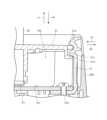
図6及び図7は、収容部100に体外パドル30が収容された状態において、進退部21を通る鉛直面によって上部ケース20aと体外パドル30とを切った断面図である。特に、図6は体外パドル30に成人用電極部40が取り付けられた状態での断面図であり、図7は体外パドル30から成人用電極部40が取り外された状態での断面図である。Figures 6 and 7 are cross-sectional views of the
先ず、進退部21の構成について詳しく説明する。進退部21は樹脂からなる断面がL字状の部材である。進退部21の基台部はネジ21bによって上部ケース20aに固定されている。ここで、上述したように、体外式除細動器10において、進退部21は1つの収容部100につき2個、よって、合計4個の進退部21が設けられている。各進退部21を上部ケース20aに固定している合計4つのネジ21bは、上部ケース20aを除細動器本体20に固定する機能も有する。つまり、ネジ21bの先端は、除細動器本体20にまで達している。First, the configuration of the advance/retract
これにより、本実施の形態においては、ネジ21bによって、上部ケース20aへの進退部21の固定と同時に、除細動器本体20への上部ケース20aの固定も行うことができるようになっている。進退部21が上部ケース20aと一体に成形されておらず、別体とされていることにより、進退部21が破損した場合に、上部ケース20a全体を交換することなく破損した進退部21のみを交換すればよい。この結果、メンテナンス性を向上させることができる。As a result, in this embodiment, the
進退部21の立ち上がり部の先端近傍には体外パドル30の方向に突き出た爪21aが形成されている。爪21aは、進退部21自体の弾性により、矢印d1で示した前進方向及び矢印d2で示した後退方向に移動可能となっている。A
次に、進退部21の動作について説明する。Next, the operation of the advance/retract
図6に示したように、成人用電極部40が取り付けられた体外パドル30がユーザーによって収容方向c2に移動されて収容部100に収容されると、進退部21の爪21aが第2のフランジ31aの上面に当接することにより、体外パドル30の収容部100からの逸脱方向c1への移動が規制されて、体外パドル30が収容部100内の所定位置に保持される。この所定位置とは、成人用電極P2の表面が収容部100の底面部101にほぼ一致する位置である。As shown in FIG. 6, when the
厳密に言うと、この所定位置において、成人用電極P2の表面は収容部100の底面部101から若干浮いた状態となる。これは、体外パドル30がテスト用電極110のバネ力によって逸脱方向c1に付勢されるためである。換言すれば、爪21a及びフランジ31aとの位置関係と、テスト用電極110の付勢力と、により、成人用電極P2の表面が収容部100の底面部101から所定距離若干浮いた状態に位置決めされる。これにより、上記所定位置においては、成人用電極P2の表面には底面部101は当接せずテスト用電極110のみが当接するので、成人用電極P2とテスト用電極110との電気的接続の信頼性が向上する。Strictly speaking, at this predetermined position, the surface of the adult electrode P2 is slightly raised above the
ユーザーは、除細動の処置を行う際には、体外パドル30のハンドル部30aを持って、図6の収容位置から、体外パドル30を逸脱方向c1に引っ張り上げる。このとき、引っ張り力が進退部21の弾性力に打ち勝つと、進退部21の爪21aが後退方向d2に移動する。この結果、爪21aが第2のフランジ31aを乗り越え、体外パドル30が逸脱方向c1に移動する。When performing defibrillation, the user holds the
一方、図7に示したように、成人用電極部40が取り外された体外パドル30が収容部100に収容されると、進退部21の爪21aが第1のフランジ31の上面に当接することにより、体外パドル30の収容部100からの逸脱方向c1への移動が規制されて、体外パドル30が収容部100内の所定位置に保持される。この所定位置とは、小児用電極P1の表面が収容部100の底面部101にほぼ当接する位置である。On the other hand, as shown in FIG. 7, when the
厳密に言うと、この所定位置において、小児用電極P1の表面は収容部100の底面部101から若干浮いた状態となる。これは、体外パドル30がテスト用電極110のバネ力によって逸脱方向c1に付勢されるためである。換言すれば、爪21a及びフランジ31との位置関係と、テスト用電極110の付勢力と、により、小児用電極P1の表面が収容部100の底面部101から所定距離若干浮いた状態に位置決めされる。これにより、上記所定位置においては、小児用電極P1の表面には底面部101は当接せずテスト用電極110のみが当接するので、小児用電極P1とテスト用電極110との電気的接続の信頼性が向上する。Strictly speaking, at this predetermined position, the surface of the pediatric electrode P1 is slightly raised above the
ユーザーは、除細動の処置を行う際には、体外パドル30のハンドル部30aを持って、図7の収容位置から、体外パドル30を逸脱方向c1に引っ張り上げる。このとき、引っ張り力が進退部21の弾性力に打ち勝つと、進退部21の爪21aが後退方向d2に移動する。この結果、爪21aが第1のフランジ31を乗り越え、さらには第2のフランジ31aを乗り越えて、体外パドル30が逸脱方向c1に移動する。When performing defibrillation, the user holds the
このように、第1及び第2のフランジ31、31aと進退部21とによって、小児用電極P1及び成人用電極P2のどちらもテスト用電極110に一定の力で当接されるようになる。この結果、小児用電極P1とテスト用電極110との接触圧と、成人用電極P2とテスト用電極110との接触圧がほぼ同じとなり、均等な接触抵抗の下での通電テストを行うことができるようになり、通電テストの信頼性が向上する。例えば、ユーザーによって体外パドル30を下方に押圧してテスト用電極110との当接を確保する場合と比較して、通電テストの信頼性が向上する。In this way, the first and
<4>収容部への体外パドルの立て掛け
本実施の形態では、収容部100に体外パドル30を立て掛けることができるようになっている。 <4> Leaning the Extracorporeal Paddle Against the Container In this embodiment, the
図8及び図9は、それぞれ、収容部100に体外パドル30を立て掛けた状態を示す斜視図及び平面図である。なお、図8及び図9では、成人用電極部40を取り付けた体外パドル30を立て掛けた状態が示されているが、勿論、成人用電極部40を取り外した状態の体外パドル30を立て掛けることもできる。Figures 8 and 9 are perspective and plan views, respectively, showing the
収容部100の側壁には長孔22が形成されている。長孔22は、上部ケース20aの側壁(収容部100の側壁と言ってもよい)を上下方向に亘って切り欠いたものであり、一端が上部ケース20aの上端位置(収容部100の上端位置と言ってもよい)で開口しているとともに他端(下端)が上部ケース20aの底面部101(収容部100の底面部101と言ってもよい)に達しており、かつ孔幅が体外パドル30のフランジ31の厚みよりも大きい。A
長孔22に対向する上部ケース20aの壁面には、上下方向に亘って延びる案内溝23が形成されている。案内溝23の溝幅は体外パドル30のフランジ31の厚みよりも大きい。A
図8及び図9から分かるように、体外パドル30は、長孔22及び案内溝23に上方からフランジ31を差し込むことにより、収容部100に立て掛けることができる。As can be seen from Figures 8 and 9, the
長孔22及び案内溝23は、長孔22及び案内溝23に体外パドル30のフランジ31が差し込まれたときに、体外パドル30のハンドル部30aが収容部100の外部に配置されるような位置に形成されている。これにより、ユーザーが収容部100の外からハンドル部30aを容易に把持できるようになる。また、ハンドル部30aとフランジ31とで上部ケース20aの壁面を挟持することにより、ハンドル部30の立て掛け状態が安定する。The
ここで、実際に体外式除細動器10が使用される場合には、ユーザーは、先ず収容部100から体外パドル30を取り出して、次に使用する電極P1又はP2に導電性ジェルを塗る。次に、ユーザーは、体外式除細動器10の電源を入れ、体外パドル30を患者の胸部に押し当てる。この状態で体外式除細動器10によって患者の心電図が取得される。When the
次に、ユーザーによってショックボタンが押されると、体外パドル30から患者に電気エネルギーが供給されて電気的除細動が行われる。次に、ユーザーは、必要に応じて患者に心臓マッサージなどの処置を行う。その後、ユーザーは、必要に応じて再び体外パドル30を患者の胸部に押し当てて除細動の処置を行う。Next, when the user presses the shock button, electrical energy is supplied from the
ここで、処置を行う者が2人以上存在する場合には、体外パドル30により除細動の処置を行う者と心臓マッサージなどの処置を行う者とで役割分担を行うことができる。従って、除細動の処置を行う者は、1回目の除細動の処置を行った後に他の者が心臓マッサージなどの処置を行っている時間そのまま体外パドル30を持ったままで待機し、2回目の除細動の処置を行うことができる。Here, if there are two or more people performing treatment, the roles can be divided between those who perform defibrillation using the
これに対して、処置を行う者が1人しか存在しない場合には、除細動の処置を行う者が心臓マッサージなどの処置も行う必要がある。この場合、心臓マッサージなどの処置を行う際には、体外パドル30をどこかに置かなければならない。On the other hand, if there is only one person performing treatment, the person performing the defibrillation treatment must also perform treatments such as cardiac massage. In this case, the
本実施の形態の場合には、体外パドル30を図8及び図9に示したように収容部100に立て掛けておくことができるので便利である。特に、体外パドル30を床や地面に直接置くと、導電性ジェルが汚れるおそれがあり好ましくない。また、体外パドル30を図6や図7に示したように収容部100に完全に収容してしまうと、収容部100の底面部101やテスト用電極110に導電性ジェルが付着するおそれがあるので好ましくない。本実施の形態の構成によれば、このような不都合を回避できる。In the present embodiment, the
また、上述したように、長孔22の下端は、上部ケース20aの底面部101に達している。これにより、長孔22は水抜き孔として機能し、収容部100に水が貯まることが防止される。As described above, the lower end of the
さらに、本実施の形態の場合には、収容部100の底面部101は、長孔22の下端に向かって低くなるように傾斜している。これにより、収容部100での水貯まりをより防止できるようになる。また、長孔22の下端の高さを、テスト用電極110の取り付け部の高さよりも低くすることが好ましい。このようにすることで、水貯まりの影響を受け易いテスト用電極110が水に浸ることを防止できる。Furthermore, in this embodiment, the
このように、本実施の形態の構成によれば、長孔22に、収容部100の水抜きの機能と体外パドル30の立て掛けの機能とを持たせたので、簡易な構成により、水抜き機能と立て掛け機能とを実現できる。In this way, according to the configuration of this embodiment, the
<5>実施の形態の効果
以上説明したように、本実施の形態の体外式除細動器10は、収容部100の側壁を上下方向に亘って切り欠いた長孔22であり、一端が収容部100の上端位置で開口しているとともに他端が少なくとも収容部100の底面部101まで達しており、かつ孔幅が体外パドル30のフランジ31の厚みよりも大きい、長孔22を有する。 <5> Effects of the embodiment As described above, the
これにより、長孔22によって、収容部100に水が貯まることが防止され、かつ、フランジ31を介して体外パドル30を立て掛けることもできるようになる。この結果、収容部100に水が貯まることを防止できるとともに、ユーザーによる除細動処置の利便性を向上させることができる体外式除細動器10を実現できる。The
特に、上述の実施の形態では、フランジ31を長孔22に差し込むといった構成となっているので、体外パドル30に成人用電極部40が取り付けられているかいないかにかかわらず、体外パドル30を収容部100に安定して係合させることができ、安定した立て掛けを実現できる。In particular, in the above-described embodiment, the
<6>他の実施の形態
上述の実施の形態は、本発明を実施するにあたっての具体化の一例を示したものに過ぎず、これらによって本発明の技術的範囲が限定的に解釈されてはならないものである。すなわち、本発明はその要旨、またはその主要な特徴から逸脱することなく、様々な形で実施することができる。 <6> Other Embodiments The above-described embodiments are merely examples of the embodiment of the present invention, and the technical scope of the present invention should not be interpreted as being limited by these embodiments. In other words, the present invention can be embodied in various forms without departing from the gist or main characteristics of the present invention.
上述の実施の形態では、第2の係合部を、第1の収容位置で進退部21に当接する上面を有する第1のフランジ31と、第1の収容位置よりも低い第2の収容位置で進退部21に当接する上面を有する第2のフランジ31aと、を有するように構成した場合について述べたが、本発明はこれに限らない。要は、第1及び第2の係合部を、体外パドル30を収容部100内における深さの異なる第1及び第2の収容位置で保持できるように構成すればよい。In the above embodiment, the second engagement portion is configured to have a
図6及び図7との対応部分に同一符号を付して示した図10及び図11は、他の実施の形態の構成を示す断面図である。図10及び図11の構成では、第1の係合部としての進退部21は、第1の収容位置で第2の係合部(フランジ31a)に係合する第1の進退部材(爪21a)と、第1の収容位置よりも低い第2の収容位置で第2の係合部(フランジ31a)に係合する第2の進退部材(爪21c)と、を有する。Figures 10 and 11, in which parts corresponding to those in Figures 6 and 7 are denoted by the same reference numerals, are cross-sectional views showing the configuration of another embodiment. In the configuration of Figures 10 and 11, the advance/retract
図10に示したように、第1の進退部材(爪21a)の位置と第2の進退部材(爪21c)の位置との差t1は、成人用電極部40を取り付けたときと成人用電極部40を取り外したときの体外パドル30の厚さの差t2に等しい。As shown in FIG. 10, the difference t1 between the position of the first advancing/retracting member (claw 21a) and the position of the second advancing/retracting member (claw 21c) is equal to the difference t2 in the thickness of the
このような構成でも、上述の実施の形態と同様の効果を得ることができる。With this configuration, the same effects as those of the above embodiment can be obtained.
具体的に説明する。図10に示したように、成人用電極部40が取り付けられた体外パドル30が収容部100に収容されると、進退部21の爪21aがフランジ31aの上面に当接することにより、体外パドル30の収容部100からの逸脱方向c1への移動が規制されて、体外パドル30が収容部100内の所定位置に保持される。As shown in FIG. 10, when the
一方、図11に示したように、成人用電極部40が取り外された体外パドル30が収容部100に収容されると、進退部21の爪21cがフランジ31aの上面に当接することにより、体外パドル30の収容部100からの逸脱方向c1への移動が規制されて、体外パドル30が収容部100内の所定位置に保持される。On the other hand, as shown in FIG. 11, when the
上述の実施の形態では、収容部100に第1の係合部として進退部21を形成し、体外パドル30に第2の係合部としてフランジ31、31aを形成する場合について述べたが、本発明はこれに限らない。例えば、収容部100に第1の係合部としてフランジを形成し、体外パドル30に第2の係合部として進退部を形成してもよい。さらに、第1の係合部及び第2の係合部は、上述の実施の形態のような進退部21及びフランジ31、31aに限らず、要は、第1の係合部と第2の係合部は、体外パドルを収容部内における深さの異なる第1及び第2の収容位置で保持できる構成であればよい。In the above embodiment, the advancing/retreating
上述の実施の形態では、長孔22によって、収容部100に水が貯まることを防止するとともに体外パドル30の立て掛けを実現した場合について述べたが、本発明はこれに限らない。要は、収容部100に、収容空間の底部が外部に連通するような連通部を形成し、この連通部の形状を、体外パドル30の一部が係合可能なようにすればよい。このような構成により、連通部によって収容空間内の水抜きと体外パドルの立て掛けを実現できる。In the above embodiment, the
ただし、上述の実施の形態の長孔22は、収容空間100内に凹凸を形成する必要がないので、収容空間100内への汚れの付着が少なくかつ掃除が容易である。よって、水抜きと立て掛けの機能を衛生的に実現できるといった、医療機器にとって大きなメリットがある。However, the
本発明は、パドル収容部を有する体外式除細動器に広く適用可能である。The present invention is widely applicable to external defibrillators that have a paddle housing.
10 体外式除細動器
20 除細動器本体
20a 上部ケース
21 進退部
21a、21c 係合爪
21b ネジ
22 長孔
23 案内溝
30 体外パドル
30a ハンドル部
31、31a フランジ
40 成人用電極部
50 接続コード
60 本体ハンドル部
100 収容部
101 底面部
110 テスト用電極 REFERENCE SIGNS
Claims (6)
Translated fromJapanese前記体外パドルが接続され、前記体外パドルに除細動のための電気エネルギーを供給する除細動器本体と、
前記体外パドルを収容する凹状の収容空間を有する収容部と、
前記収容空間の底部が外部に連通するように前記収容部に形成された連通部と、
を有し、
前記連通部は、前記体外パドルの一部が係合可能な形状とされている、
体外式除細動器。 A pair of external paddles each having an electrode portion capable of coming into contact with a body surface of a patient;
a defibrillator main body to which the external paddle is connected and which supplies electrical energy for defibrillation to the external paddle;
A housing portion having a concave housing space for housing the external paddle;
a communication portion formed in the storage portion such that a bottom portion of the storage space is in communication with the outside;
having
The communication portion is shaped so that a part of the extracorporeal paddle can be engaged therewith.
External defibrillator.
前記収容部の側壁を上下方向に亘って切り欠いた長孔であり、当該長孔は、一端が前記収容部の上端位置で開口しているとともに他端が少なくとも前記収容部の底面まで達しており、かつ孔幅が前記体外パドルのフランジの厚みよりも大きい、
請求項1に記載の体外式除細動器。 The communication portion is
a long hole formed by cutting a side wall of the storage section in the vertical direction, one end of the long hole being open at the upper end position of the storage section and the other end reaching at least the bottom surface of the storage section, and a hole width being larger than a thickness of a flange of the extracorporeal paddle;
2. The external defibrillator of claim 1.
請求項2に記載の体外式除細動器。 Further, a guide groove extending in the vertical direction is formed on a side wall of the housing portion facing the long hole, and a groove width of the guide groove is larger than a thickness of a flange of the extracorporeal paddle.
3. The external defibrillator of claim 2.
請求項2又は3に記載の体外式除細動器。 the long hole is formed at a position such that a handle portion of the extracorporeal paddle is disposed outside the housing portion when the flange of the extracorporeal paddle is inserted into the long hole;
4. An external defibrillator according to claim 2 or 3.
請求項2から4のいずれか一項に記載の体外式除細動器。 The bottom surface of the storage portion is inclined so as to become lower toward the other end of the slot.
5. An external defibrillator according to any one of claims 2 to 4.
前記長孔の他端の高さは、前記電極の取り付け部の高さよりも低い、
請求項2から5のいずれか一項に記載の体外式除細動器。
An electrode is provided on the bottom surface of the storage portion,
The height of the other end of the long hole is lower than the height of the attachment portion of the electrode.
6. An external defibrillator according to any one of claims 2 to 5.
Priority Applications (1)
| Application Number | Priority Date | Filing Date | Title |
|---|---|---|---|
| JP2021097954AJP7644662B2 (en) | 2021-06-11 | 2021-06-11 | External defibrillators |
Applications Claiming Priority (1)
| Application Number | Priority Date | Filing Date | Title |
|---|---|---|---|
| JP2021097954AJP7644662B2 (en) | 2021-06-11 | 2021-06-11 | External defibrillators |
Publications (2)
| Publication Number | Publication Date |
|---|---|
| JP2022189399A JP2022189399A (en) | 2022-12-22 |
| JP7644662B2true JP7644662B2 (en) | 2025-03-12 |
Family
ID=84533010
Family Applications (1)
| Application Number | Title | Priority Date | Filing Date |
|---|---|---|---|
| JP2021097954AActiveJP7644662B2 (en) | 2021-06-11 | 2021-06-11 | External defibrillators |
Country Status (1)
| Country | Link |
|---|---|
| JP (1) | JP7644662B2 (en) |
Citations (4)
| Publication number | Priority date | Publication date | Assignee | Title |
|---|---|---|---|---|
| JP2012005661A (en) | 2010-06-24 | 2012-01-12 | Katsuhiro Iida | Outdoor type aed storage box |
| JP2012520738A (en) | 2009-03-17 | 2012-09-10 | カーディオスライヴ インコーポレイテッド | External defibrillator |
| JP2016087361A (en) | 2014-11-11 | 2016-05-23 | フクダ電子株式会社 | External defibrillator |
| CN210057147U (en) | 2019-04-26 | 2020-02-14 | 朱涛 | A cardiac defibrillator for cardiac surgery |
Family Cites Families (4)
| Publication number | Priority date | Publication date | Assignee | Title |
|---|---|---|---|---|
| US4628935A (en)* | 1985-01-08 | 1986-12-16 | Physio-Control Corporation | Defibrillator adapted for use with accessory cassettes |
| US4779630A (en)* | 1987-09-18 | 1988-10-25 | Katecho, Inc. | Defibrillator pad assembly and method for using same |
| US5148805A (en)* | 1991-02-11 | 1992-09-22 | Kas Products, Inc. | Defibrillator pad system and method for using same |
| US5690684A (en)* | 1995-05-02 | 1997-11-25 | Hewlett-Packard Company | Pivot assisted defibrillator paddle retainer |
- 2021
- 2021-06-11JPJP2021097954Apatent/JP7644662B2/enactiveActive
Patent Citations (4)
| Publication number | Priority date | Publication date | Assignee | Title |
|---|---|---|---|---|
| JP2012520738A (en) | 2009-03-17 | 2012-09-10 | カーディオスライヴ インコーポレイテッド | External defibrillator |
| JP2012005661A (en) | 2010-06-24 | 2012-01-12 | Katsuhiro Iida | Outdoor type aed storage box |
| JP2016087361A (en) | 2014-11-11 | 2016-05-23 | フクダ電子株式会社 | External defibrillator |
| CN210057147U (en) | 2019-04-26 | 2020-02-14 | 朱涛 | A cardiac defibrillator for cardiac surgery |
Also Published As
| Publication number | Publication date |
|---|---|
| JP2022189399A (en) | 2022-12-22 |
Similar Documents
| Publication | Publication Date | Title |
|---|---|---|
| EP0217383A2 (en) | Electrocadiographic electrode | |
| ATE507870T1 (en) | TRANSSEPTAL/TRANSMYOCARDIAL VENTRICULAR PACING LEAD | |
| US4773424A (en) | Electrocardiographic electrode | |
| JP7644662B2 (en) | External defibrillators | |
| US20220409898A1 (en) | Electric device for skin treatment and control method therefor | |
| JP7686463B2 (en) | external defibrillator | |
| US5277613A (en) | Electrode junction assembly | |
| DK150841B (en) | CONNECTOR FOR ESTABLISHING ELECTRICAL CONNECTION WITH A disposable skin electrode | |
| CN208677386U (en) | A kind of multi-functional switching folder | |
| CN208923469U (en) | A kind of integral type cardiac diagnosis lead-line instrument side plug | |
| EP1541190A1 (en) | Electromedical electrode with a detachable cable connector | |
| CN218900270U (en) | Double-switch starting energy-saving protection type disinfection box for electric toothbrush | |
| CN115721854B (en) | Electrode catheter structure and pacing electrode catheter device | |
| CN214105127U (en) | Massage device | |
| JP6444695B2 (en) | External defibrillator | |
| KR102495584B1 (en) | Wet tissue warmer | |
| JP2023512842A (en) | Electrical connectors and covers for simultaneous connection of epicardial wires, bedside monitors and temporary pacemakers | |
| CN220320915U (en) | Supporting seat and monitoring equipment | |
| CN215457511U (en) | Folding foot tub | |
| CN221266675U (en) | Acupuncture needle for electric stimulation of small animal acupuncture points | |
| CN219374686U (en) | Electrocardiogram monitor circuit disinfection and arrangement device | |
| CN213157599U (en) | Dredging massage head of eye nursing equipment | |
| CN215084277U (en) | Automatic external defibrillator | |
| CN215383265U (en) | Cooking utensil | |
| KR0135345B1 (en) | Sole Low Frequency Therapy |
Legal Events
| Date | Code | Title | Description |
|---|---|---|---|
| A621 | Written request for application examination | Free format text:JAPANESE INTERMEDIATE CODE: A621 Effective date:20240502 | |
| A977 | Report on retrieval | Free format text:JAPANESE INTERMEDIATE CODE: A971007 Effective date:20241211 | |
| TRDD | Decision of grant or rejection written | ||
| A01 | Written decision to grant a patent or to grant a registration (utility model) | Free format text:JAPANESE INTERMEDIATE CODE: A01 Effective date:20250204 | |
| A61 | First payment of annual fees (during grant procedure) | Free format text:JAPANESE INTERMEDIATE CODE: A61 Effective date:20250228 | |
| R150 | Certificate of patent or registration of utility model | Ref document number:7644662 Country of ref document:JP Free format text:JAPANESE INTERMEDIATE CODE: R150 |