JP7642219B2 - Luminous body, luminous element, and method of using as luminous body - Google Patents
Luminous body, luminous element, and method of using as luminous bodyDownload PDFInfo
- Publication number
- JP7642219B2 JP7642219B2JP2018555029AJP2018555029AJP7642219B2JP 7642219 B2JP7642219 B2JP 7642219B2JP 2018555029 AJP2018555029 AJP 2018555029AJP 2018555029 AJP2018555029 AJP 2018555029AJP 7642219 B2JP7642219 B2JP 7642219B2
- Authority
- JP
- Japan
- Prior art keywords
- molecule
- electron donor
- phosphorescent
- electron
- electron acceptor
- Prior art date
- Legal status (The legal status is an assumption and is not a legal conclusion. Google has not performed a legal analysis and makes no representation as to the accuracy of the status listed.)
- Active
Links
- 238000000034methodMethods0.000titleclaimsdescription13
- 239000000463materialSubstances0.000claimsdescription134
- 230000005284excitationEffects0.000claimsdescription53
- 125000003118aryl groupChemical group0.000claimsdescription48
- 150000001875compoundsChemical class0.000claimsdescription48
- 125000001424substituent groupChemical group0.000claimsdescription35
- 239000000203mixtureSubstances0.000claimsdescription29
- 150000005839radical cationsChemical class0.000claimsdescription25
- 150000005838radical anionsChemical class0.000claimsdescription24
- 125000000732arylene groupChemical group0.000claimsdescription22
- 125000001072heteroaryl groupChemical group0.000claimsdescription22
- 229920000642polymerPolymers0.000claimsdescription18
- 125000000217alkyl groupChemical group0.000claimsdescription13
- 238000005215recombinationMethods0.000claimsdescription10
- 230000006798recombinationEffects0.000claimsdescription10
- 125000004663dialkyl amino groupChemical group0.000claimsdescription8
- -1diphenylamino groupChemical group0.000claimsdescription8
- 125000005549heteroarylene groupChemical group0.000claimsdescription8
- 125000004435hydrogen atomChemical group[H]*0.000claimsdescription8
- 238000003860storageMethods0.000claimsdescription8
- 125000001997phenyl groupChemical group[H]C1=C([H])C([H])=C(*)C([H])=C1[H]0.000claimsdescription7
- 229910052760oxygenInorganic materials0.000claimsdescription5
- 229910052717sulfurInorganic materials0.000claimsdescription4
- 239000010408filmSubstances0.000description88
- 238000000295emission spectrumMethods0.000description47
- 230000008859changeEffects0.000description46
- 238000004020luminiscence typeMethods0.000description46
- 238000004768lowest unoccupied molecular orbitalMethods0.000description34
- 125000004432carbon atomChemical groupC*0.000description31
- YXFVVABEGXRONW-UHFFFAOYSA-NTolueneChemical compoundCC1=CC=CC=C1YXFVVABEGXRONW-UHFFFAOYSA-N0.000description27
- 239000000243solutionSubstances0.000description27
- 238000004770highest occupied molecular orbitalMethods0.000description20
- 239000011521glassSubstances0.000description19
- YMWUJEATGCHHMB-UHFFFAOYSA-NDichloromethaneChemical compoundClCClYMWUJEATGCHHMB-UHFFFAOYSA-N0.000description18
- 239000000758substrateSubstances0.000description17
- 238000000862absorption spectrumMethods0.000description15
- 229920005989resinPolymers0.000description15
- 239000011347resinSubstances0.000description15
- 238000011156evaluationMethods0.000description14
- 230000003111delayed effectEffects0.000description13
- 230000007246mechanismEffects0.000description13
- 125000000623heterocyclic groupChemical group0.000description12
- 150000002894organic compoundsChemical class0.000description12
- 238000002360preparation methodMethods0.000description12
- DIVZFUBWFAOMCW-UHFFFAOYSA-N4-n-(3-methylphenyl)-1-n,1-n-bis[4-(n-(3-methylphenyl)anilino)phenyl]-4-n-phenylbenzene-1,4-diamineChemical compoundCC1=CC=CC(N(C=2C=CC=CC=2)C=2C=CC(=CC=2)N(C=2C=CC(=CC=2)N(C=2C=CC=CC=2)C=2C=C(C)C=CC=2)C=2C=CC(=CC=2)N(C=2C=CC=CC=2)C=2C=C(C)C=CC=2)=C1DIVZFUBWFAOMCW-UHFFFAOYSA-N0.000description11
- JWUJQDFVADABEY-UHFFFAOYSA-N2-methyltetrahydrofuranChemical compoundCC1CCCO1JWUJQDFVADABEY-UHFFFAOYSA-N0.000description10
- 238000005259measurementMethods0.000description10
- 239000003973paintSubstances0.000description10
- 230000008569processEffects0.000description10
- 125000005842heteroatomChemical group0.000description9
- MPQXHAGKBWFSNV-UHFFFAOYSA-NoxidophosphaniumChemical group[PH3]=OMPQXHAGKBWFSNV-UHFFFAOYSA-N0.000description9
- 239000010409thin filmSubstances0.000description9
- 238000010521absorption reactionMethods0.000description7
- 230000000052comparative effectEffects0.000description7
- 229910052761rare earth metalInorganic materials0.000description7
- 238000000926separation methodMethods0.000description7
- 229920000491PolyphenylsulfonePolymers0.000description6
- 125000004429atomChemical group0.000description6
- 238000013461designMethods0.000description6
- 238000004519manufacturing processMethods0.000description6
- 238000001296phosphorescence spectrumMethods0.000description6
- ATTVYRDSOVWELU-UHFFFAOYSA-N1-diphenylphosphoryl-2-(2-diphenylphosphorylphenoxy)benzeneChemical compoundC=1C=CC=CC=1P(C=1C(=CC=CC=1)OC=1C(=CC=CC=1)P(=O)(C=1C=CC=CC=1)C=1C=CC=CC=1)(=O)C1=CC=CC=C1ATTVYRDSOVWELU-UHFFFAOYSA-N0.000description5
- 101100207324Arabidopsis thaliana TPPD geneProteins0.000description5
- 125000005647linker groupChemical group0.000description5
- 239000012299nitrogen atmosphereSubstances0.000description5
- 150000003839saltsChemical class0.000description5
- 239000002904solventSubstances0.000description5
- 238000001228spectrumMethods0.000description5
- 230000007704transitionEffects0.000description5
- SECXISVLQFMRJM-UHFFFAOYSA-NN-MethylpyrrolidoneChemical compoundCN1CCCC1=OSECXISVLQFMRJM-UHFFFAOYSA-N0.000description4
- 125000003277amino groupChemical class0.000description4
- 238000002484cyclic voltammetryMethods0.000description4
- ZUOUZKKEUPVFJK-UHFFFAOYSA-NdiphenylChemical groupC1=CC=CC=C1C1=CC=CC=C1ZUOUZKKEUPVFJK-UHFFFAOYSA-N0.000description4
- 238000002189fluorescence spectrumMethods0.000description4
- 230000005283ground stateEffects0.000description4
- 239000000155meltSubstances0.000description4
- 239000003960organic solventSubstances0.000description4
- 125000000843phenylene groupChemical groupC1(=C(C=CC=C1)*)*0.000description4
- 239000010453quartzSubstances0.000description4
- VYPSYNLAJGMNEJ-UHFFFAOYSA-Nsilicon dioxideInorganic materialsO=[Si]=OVYPSYNLAJGMNEJ-UHFFFAOYSA-N0.000description4
- UHOVQNZJYSORNB-UHFFFAOYSA-NBenzeneChemical groupC1=CC=CC=C1UHOVQNZJYSORNB-UHFFFAOYSA-N0.000description3
- 125000003342alkenyl groupChemical group0.000description3
- 125000003545alkoxy groupChemical group0.000description3
- 125000000304alkynyl groupChemical group0.000description3
- 150000004945aromatic hydrocarbonsChemical class0.000description3
- 239000011248coating agentSubstances0.000description3
- 238000000576coating methodMethods0.000description3
- 239000003086colorantSubstances0.000description3
- 238000010586diagramMethods0.000description3
- 238000001035dryingMethods0.000description3
- 125000006575electron-withdrawing groupChemical group0.000description3
- 239000000835fiberSubstances0.000description3
- 230000001443photoexcitationEffects0.000description3
- 239000000126substanceSubstances0.000description3
- 230000001052transient effectEffects0.000description3
- YOILXOMTHPUMRG-JSGCOSHPSA-N(4as,10bs)-4-propyl-3,4a,5,10b-tetrahydro-2h-chromeno[4,3-b][1,4]oxazin-9-olChemical compoundC1=C(O)C=C2[C@@H]3OCCN(CCC)[C@H]3COC2=C1YOILXOMTHPUMRG-JSGCOSHPSA-N0.000description2
- 238000004435EPR spectroscopyMethods0.000description2
- 238000004847absorption spectroscopyMethods0.000description2
- 125000004414alkyl thio groupChemical group0.000description2
- 230000008901benefitEffects0.000description2
- 239000004305biphenylChemical group0.000description2
- 235000010290biphenylNutrition0.000description2
- 239000004566building materialSubstances0.000description2
- 239000000470constituentSubstances0.000description2
- GPAYUJZHTULNBE-UHFFFAOYSA-NdiphenylphosphineChemical compoundC=1C=CC=CC=1PC1=CC=CC=C1GPAYUJZHTULNBE-UHFFFAOYSA-N0.000description2
- 239000006185dispersionSubstances0.000description2
- 230000005274electronic transitionsEffects0.000description2
- 238000000695excitation spectrumMethods0.000description2
- 230000005281excited stateEffects0.000description2
- 230000009975flexible effectEffects0.000description2
- 239000000976inkSubstances0.000description2
- 229910010272inorganic materialInorganic materials0.000description2
- 239000011147inorganic materialSubstances0.000description2
- 238000002844meltingMethods0.000description2
- 230000008018meltingEffects0.000description2
- 239000011259mixed solutionSubstances0.000description2
- 238000002156mixingMethods0.000description2
- 239000000178monomerSubstances0.000description2
- 239000002245particleSubstances0.000description2
- 229910052698phosphorusInorganic materials0.000description2
- 238000001420photoelectron spectroscopyMethods0.000description2
- 238000005424photoluminescenceMethods0.000description2
- 230000000379polymerizing effectEffects0.000description2
- 230000002265preventionEffects0.000description2
- 238000012545processingMethods0.000description2
- 238000011160researchMethods0.000description2
- 239000012780transparent materialSubstances0.000description2
- RFDGVZHLJCKEPT-UHFFFAOYSA-Ntris(2,4,6-trimethyl-3-pyridin-3-ylphenyl)boraneChemical compoundCC1=C(B(C=2C(=C(C=3C=NC=CC=3)C(C)=CC=2C)C)C=2C(=C(C=3C=NC=CC=3)C(C)=CC=2C)C)C(C)=CC(C)=C1C1=CC=CN=C1RFDGVZHLJCKEPT-UHFFFAOYSA-N0.000description2
- VOXZDWNPVJITMN-ZBRFXRBCSA-N17β-estradiolChemical compoundOC1=CC=C2[C@H]3CC[C@](C)([C@H](CC4)O)[C@@H]4[C@@H]3CCC2=C1VOXZDWNPVJITMN-ZBRFXRBCSA-N0.000description1
- CINYXYWQPZSTOT-UHFFFAOYSA-N3-[3-[3,5-bis(3-pyridin-3-ylphenyl)phenyl]phenyl]pyridineChemical compoundC1=CN=CC(C=2C=C(C=CC=2)C=2C=C(C=C(C=2)C=2C=C(C=CC=2)C=2C=NC=CC=2)C=2C=C(C=CC=2)C=2C=NC=CC=2)=C1CINYXYWQPZSTOT-UHFFFAOYSA-N0.000description1
- WPUSEOSICYGUEW-UHFFFAOYSA-N4-[4-(4-methoxy-n-(4-methoxyphenyl)anilino)phenyl]-n,n-bis(4-methoxyphenyl)anilineChemical compoundC1=CC(OC)=CC=C1N(C=1C=CC(=CC=1)C=1C=CC(=CC=1)N(C=1C=CC(OC)=CC=1)C=1C=CC(OC)=CC=1)C1=CC=C(OC)C=C1WPUSEOSICYGUEW-UHFFFAOYSA-N0.000description1
- AWXGSYPUMWKTBR-UHFFFAOYSA-N4-carbazol-9-yl-n,n-bis(4-carbazol-9-ylphenyl)anilineChemical compoundC12=CC=CC=C2C2=CC=CC=C2N1C1=CC=C(N(C=2C=CC(=CC=2)N2C3=CC=CC=C3C3=CC=CC=C32)C=2C=CC(=CC=2)N2C3=CC=CC=C3C3=CC=CC=C32)C=C1AWXGSYPUMWKTBR-UHFFFAOYSA-N0.000description1
- ZOKIJILZFXPFTO-UHFFFAOYSA-N4-methyl-n-[4-[1-[4-(4-methyl-n-(4-methylphenyl)anilino)phenyl]cyclohexyl]phenyl]-n-(4-methylphenyl)anilineChemical compoundC1=CC(C)=CC=C1N(C=1C=CC(=CC=1)C1(CCCCC1)C=1C=CC(=CC=1)N(C=1C=CC(C)=CC=1)C=1C=CC(C)=CC=1)C1=CC=C(C)C=C1ZOKIJILZFXPFTO-UHFFFAOYSA-N0.000description1
- IJGRMHOSHXDMSA-UHFFFAOYSA-NAtomic nitrogenChemical compoundN#NIJGRMHOSHXDMSA-UHFFFAOYSA-N0.000description1
- OKTJSMMVPCPJKN-UHFFFAOYSA-NCarbonChemical group[C]OKTJSMMVPCPJKN-UHFFFAOYSA-N0.000description1
- 229910052684CeriumInorganic materials0.000description1
- 229920000089Cyclic olefin copolymerPolymers0.000description1
- YZCKVEUIGOORGS-OUBTZVSYSA-NDeuteriumChemical compound[2H]YZCKVEUIGOORGS-OUBTZVSYSA-N0.000description1
- 229910052693EuropiumInorganic materials0.000description1
- 101000837344Homo sapiens T-cell leukemia translocation-altered gene proteinProteins0.000description1
- JUJWROOIHBZHMG-UHFFFAOYSA-NPyridineChemical groupC1=CC=NC=C1JUJWROOIHBZHMG-UHFFFAOYSA-N0.000description1
- 102100028692T-cell leukemia translocation-altered gene proteinHuman genes0.000description1
- 229910052771TerbiumInorganic materials0.000description1
- 125000002947alkylene groupChemical group0.000description1
- 238000004577artificial photosynthesisMethods0.000description1
- QVGXLLKOCUKJST-UHFFFAOYSA-Natomic oxygenChemical compound[O]QVGXLLKOCUKJST-UHFFFAOYSA-N0.000description1
- 150000001555benzenesChemical class0.000description1
- 125000003354benzotriazolyl groupChemical groupN1N=NC2=C1C=CC=C2*0.000description1
- 230000015572biosynthetic processEffects0.000description1
- 125000006267biphenyl groupChemical group0.000description1
- 229910052799carbonInorganic materials0.000description1
- 239000000969carrierSubstances0.000description1
- 238000001816coolingMethods0.000description1
- 238000002425crystallisationMethods0.000description1
- 230000008025crystallizationEffects0.000description1
- 125000004122cyclic groupChemical group0.000description1
- 238000001514detection methodMethods0.000description1
- 229910052805deuteriumInorganic materials0.000description1
- 238000011161developmentMethods0.000description1
- 229910001873dinitrogenInorganic materials0.000description1
- IIDFEIDMIKSJSV-UHFFFAOYSA-Ndipropoxyphosphinothioyloxy-dipropoxy-sulfanylidene-$l^{5}-phosphaneChemical compoundCCCOP(=S)(OCCC)OP(=S)(OCCC)OCCCIIDFEIDMIKSJSV-UHFFFAOYSA-N0.000description1
- 230000007613environmental effectEffects0.000description1
- 239000003822epoxy resinSubstances0.000description1
- 229960005309estradiolDrugs0.000description1
- 229930182833estradiolNatural products0.000description1
- 125000001495ethyl groupChemical group[H]C([H])([H])C([H])([H])*0.000description1
- 238000002474experimental methodMethods0.000description1
- 239000004744fabricSubstances0.000description1
- 239000010419fine particleSubstances0.000description1
- 238000010304firingMethods0.000description1
- 230000009477glass transitionEffects0.000description1
- 125000005843halogen groupChemical group0.000description1
- 125000002887hydroxy groupChemical group[H]O*0.000description1
- 238000005286illuminationMethods0.000description1
- 239000004615ingredientSubstances0.000description1
- 230000001678irradiating effectEffects0.000description1
- 125000001449isopropyl groupChemical group[H]C([H])([H])C([H])(*)C([H])([H])[H]0.000description1
- 230000031700light absorptionEffects0.000description1
- 239000004973liquid crystal related substanceSubstances0.000description1
- 230000005923long-lasting effectEffects0.000description1
- VSQYNPJPULBZKU-UHFFFAOYSA-Nmercury xenonChemical compound[Xe].[Hg]VSQYNPJPULBZKU-UHFFFAOYSA-N0.000description1
- 229910052751metalInorganic materials0.000description1
- 239000002184metalSubstances0.000description1
- 125000002496methyl groupChemical group[H]C([H])([H])*0.000description1
- 125000002950monocyclic groupChemical group0.000description1
- 125000004123n-propyl groupChemical group[H]C([H])([H])C([H])([H])C([H])([H])*0.000description1
- 125000001624naphthyl groupChemical group0.000description1
- 229910052757nitrogenInorganic materials0.000description1
- 125000004433nitrogen atomChemical groupN*0.000description1
- 239000001301oxygenSubstances0.000description1
- 239000005022packaging materialSubstances0.000description1
- 239000000123paperSubstances0.000description1
- 230000035699permeabilityEffects0.000description1
- 239000004033plasticSubstances0.000description1
- YJGVMLPVUAXIQN-XVVDYKMHSA-NpodophyllotoxinChemical compoundCOC1=C(OC)C(OC)=CC([C@@H]2C3=CC=4OCOC=4C=C3[C@H](O)[C@@H]3[C@@H]2C(OC3)=O)=C1YJGVMLPVUAXIQN-XVVDYKMHSA-N0.000description1
- 229920003217poly(methylsilsesquioxane)Polymers0.000description1
- 229920000647polyepoxidePolymers0.000description1
- PBMFSQRYOILNGV-UHFFFAOYSA-NpyridazineChemical groupC1=CC=NN=C1PBMFSQRYOILNGV-UHFFFAOYSA-N0.000description1
- 125000000714pyrimidinyl groupChemical group0.000description1
- 150000003254radicalsChemical class0.000description1
- 239000002994raw materialSubstances0.000description1
- 230000000630rising effectEffects0.000description1
- 239000000565sealantSubstances0.000description1
- 239000010703siliconSubstances0.000description1
- 229910052710siliconInorganic materials0.000description1
- 239000007921spraySubstances0.000description1
- 125000005415substituted alkoxy groupChemical group0.000description1
- 125000000547substituted alkyl groupChemical group0.000description1
- 125000004665trialkylsilyl groupChemical group0.000description1
- 125000001425triazolyl groupChemical group0.000description1
- 230000000007visual effectEffects0.000description1
- XLYOFNOQVPJJNP-UHFFFAOYSA-NwaterSubstancesOXLYOFNOQVPJJNP-UHFFFAOYSA-N0.000description1
Images


Classifications
- C—CHEMISTRY; METALLURGY
- C09—DYES; PAINTS; POLISHES; NATURAL RESINS; ADHESIVES; COMPOSITIONS NOT OTHERWISE PROVIDED FOR; APPLICATIONS OF MATERIALS NOT OTHERWISE PROVIDED FOR
- C09K—MATERIALS FOR MISCELLANEOUS APPLICATIONS, NOT PROVIDED FOR ELSEWHERE
- C09K11/00—Luminescent, e.g. electroluminescent, chemiluminescent materials
- C09K11/06—Luminescent, e.g. electroluminescent, chemiluminescent materials containing organic luminescent materials
- H—ELECTRICITY
- H10—SEMICONDUCTOR DEVICES; ELECTRIC SOLID-STATE DEVICES NOT OTHERWISE PROVIDED FOR
- H10K—ORGANIC ELECTRIC SOLID-STATE DEVICES
- H10K50/00—Organic light-emitting devices
- C—CHEMISTRY; METALLURGY
- C09—DYES; PAINTS; POLISHES; NATURAL RESINS; ADHESIVES; COMPOSITIONS NOT OTHERWISE PROVIDED FOR; APPLICATIONS OF MATERIALS NOT OTHERWISE PROVIDED FOR
- C09K—MATERIALS FOR MISCELLANEOUS APPLICATIONS, NOT PROVIDED FOR ELSEWHERE
- C09K2211/00—Chemical nature of organic luminescent or tenebrescent compounds
- C09K2211/10—Non-macromolecular compounds
- C09K2211/1003—Carbocyclic compounds
- C09K2211/1007—Non-condensed systems
- C—CHEMISTRY; METALLURGY
- C09—DYES; PAINTS; POLISHES; NATURAL RESINS; ADHESIVES; COMPOSITIONS NOT OTHERWISE PROVIDED FOR; APPLICATIONS OF MATERIALS NOT OTHERWISE PROVIDED FOR
- C09K—MATERIALS FOR MISCELLANEOUS APPLICATIONS, NOT PROVIDED FOR ELSEWHERE
- C09K2211/00—Chemical nature of organic luminescent or tenebrescent compounds
- C09K2211/10—Non-macromolecular compounds
- C09K2211/1003—Carbocyclic compounds
- C09K2211/1014—Carbocyclic compounds bridged by heteroatoms, e.g. N, P, Si or B
- C—CHEMISTRY; METALLURGY
- C09—DYES; PAINTS; POLISHES; NATURAL RESINS; ADHESIVES; COMPOSITIONS NOT OTHERWISE PROVIDED FOR; APPLICATIONS OF MATERIALS NOT OTHERWISE PROVIDED FOR
- C09K—MATERIALS FOR MISCELLANEOUS APPLICATIONS, NOT PROVIDED FOR ELSEWHERE
- C09K2211/00—Chemical nature of organic luminescent or tenebrescent compounds
- C09K2211/10—Non-macromolecular compounds
- C09K2211/1018—Heterocyclic compounds
Landscapes
- Chemical & Material Sciences (AREA)
- Engineering & Computer Science (AREA)
- Materials Engineering (AREA)
- Organic Chemistry (AREA)
- Physics & Mathematics (AREA)
- Optics & Photonics (AREA)
- Electroluminescent Light Sources (AREA)
- Plural Heterocyclic Compounds (AREA)
Description
Translated fromJapanese本発明は、発光時間が長い蓄光体および蓄光素子に関する。The present invention relates to a phosphorescent body and a phosphorescent element that have a long light-emitting time.
蓄光材料は、励起光が照射されている間にエネルギーを蓄え、励起光の照射が断たれた後にも、蓄えたエネルギーにより発光する発光材料である。蓄光材料は、暗所や夜間で光る時計の文字盤、標識や案内板等の文字、図形等のための夜光塗料に用いられており、最近では、電力供給がなくても照明できる蓄光照明への利用も進められている。
こうした蓄光材料の中でも、特に、発光時間が長い蓄光材料として、Eu、Ce、Tb等の希土類元素を含む無機塩が知られている(例えば、特許文献1参照)。 A phosphorescent material is a luminescent material that stores energy while being irradiated with excitation light and emits light using the stored energy even after the irradiation of the excitation light is stopped. Phosphorescent materials are used in luminous paints for clock faces that glow in the dark or at night, letters and figures on signs and guide plates, etc., and recently, their use in phosphorescent lighting that can provide illumination even without a power supply has also been promoted.
Among these phosphorescent materials, inorganic salts containing rare earth elements such as Eu, Ce, and Tb are known as phosphorescent materials that emit light for a particularly long period of time (see, for example, Patent Document 1).
しかしながら、これらの無機塩からなる蓄光材料は、良質な結晶化と粒径制御が必要であるために製造工程が複雑になることや、高価な希土類元素を用いて複雑な製造工程で製造されるため製造コストが高くなること、さらに、その無機微粒子の分散液(不均一系)を塗料に用いて蓄光膜を形成するため、均一な蓄光膜を得ることが難しい等の問題がある。さらに、透明性が確保しにくいうえ、無機塩からなる蓄光材料の多くは、励起波長が紫外域であり、紫外光が少ない励起光源を利用できないという不都合もある。
一方、有機化合物からなる蓄光材料であれば、粒径制御のような複雑な工程を行うことなく製造することができ、また、無尽蔵に存在する炭素が主な構成元素であるために製造コストを低く抑えることができる。また、有機化合物は分子設計により特性を多様に変化させることができるため、励起波長や発光波長、発光時間を容易に制御することが可能である。さらに、有機化合物は、通常、透明性を確保しやすく、多くの有機溶媒に溶解させることができるため、均一な膜を形成し易いという利点もある。
しかし、従来から用いられている有機系蓄光材料は、有機化合物である燐光材料のフォトルミネッセンスを単純に利用したものであり、その発光時間は、主として有機化合物自体の励起三重項状態の寿命(燐光の発光寿命)に依拠している。このため、従来の有機系蓄光材料では、発光時間を延ばすのにも限界があり、十分な発光時間が得られないのが実情である。
そこで本発明者らは、希土類元素を用いずに有機化合物だけで、十分な発光時間が得られる蓄光体および蓄光素子を提供することを目的として鋭意検討を進めた。 However, these phosphorescent materials made of inorganic salts have problems such as the need for good crystallization and particle size control, which makes the manufacturing process complicated, the high manufacturing cost due to the use of expensive rare earth elements in a complicated manufacturing process, and the difficulty in obtaining a uniform phosphorescent film because the phosphorescent film is formed using a dispersion (heterogeneous system) of the inorganic fine particles as a paint. Furthermore, it is difficult to ensure transparency, and many phosphorescent materials made of inorganic salts have the inconvenience that the excitation wavelength is in the ultraviolet range, making it impossible to use an excitation light source with little ultraviolet light.
On the other hand, phosphorescent materials made of organic compounds can be manufactured without complicated processes such as particle size control, and because the main constituent element is carbon, which is inexhaustible, manufacturing costs can be kept low. In addition, the properties of organic compounds can be varied in a variety of ways through molecular design, making it easy to control the excitation wavelength, emission wavelength, and emission time. Furthermore, organic compounds usually have the advantage of being easy to ensure transparency and can be dissolved in many organic solvents, making it easy to form a uniform film.
However, conventional organic phosphorescent materials simply utilize the photoluminescence of phosphorescent materials, which are organic compounds, and their emission time mainly depends on the lifetime of the excited triplet state of the organic compound itself (the phosphorescence emission lifetime). Therefore, conventional organic phosphorescent materials have a limit to how long they can extend the emission time, and the reality is that sufficient emission time cannot be obtained.
Therefore, the present inventors have carried out extensive research with the aim of providing a phosphorescent body and a phosphorescent element that can obtain a sufficient light-emitting time using only organic compounds without using rare earth elements.
鋭意検討を進めた結果、本発明者らは、特定の電子ドナー分子と特定の電子アクセプター分子を用いることにより、光照射終了後においても十分な時間発光することを見出すに至った。ここで観測された発光時間は、電子ドナー分子自体または電子アクセプター分子自体の発光寿命を上回っており、このことは予想外の発見であった。本発明は、これらの知見に基づいて提案されたものであり、以下の構成を有する。As a result of intensive research, the inventors have discovered that by using a specific electron donor molecule and a specific electron acceptor molecule, light emission continues for a sufficient period of time even after the end of light irradiation. The light emission time observed here exceeds the light emission life of the electron donor molecule itself or the electron acceptor molecule itself, which was an unexpected discovery. The present invention has been proposed based on these findings and has the following configuration.
[1] ラジカルカチオン状態が安定な電子ドナー分子とラジカルアニオン状態が安定な電子アクセプター分子を有する蓄光体であって、前記蓄光体への光照射を停止した後に10Kで発光が観測される蓄光体。
[2] 前記蓄光体への光照射を停止した後に20℃においても発光が観測される、[1]に記載の蓄光体。
[3] 前記蓄光体への光照射に伴って、前記電子ドナー分子から前記電子アクセプター分子へ電子が移動して、ラジカルカチオン状態の電子ドナー分子とラジカルアニオン状態の電子アクセプター分子が生成する、[1]または[2]に記載の蓄光体。
[4] 前記蓄光体への光照射に伴って、前記電子アクセプター分子のHOMOからLUMOへ電子が遷移する、[1]~[3]のいずれか1項に記載の蓄光体。
[5] 前記電子ドナー分子のHOMOから前記電子アクセプター分子のHOMOへ電子が移動して、ラジカルカチオン状態の電子ドナー分子とラジカルアニオン状態の電子アクセプター分子が生成する、[4]に記載の蓄光体。
[6] 前記蓄光体への光照射に伴って、前記電子ドナー分子のHOMOからLUMOへ電子が遷移する、[1]~[3]のいずれか1項に記載の蓄光体。
[7] 前記電子ドナー分子のLUMOから前記電子アクセプター分子のLUMOへ電子が移動して、ラジカルカチオン状態の電子ドナー分子とラジカルアニオン状態の電子アクセプター分子が生成する、[6]に記載の蓄光体。
[8] 前記ラジカルアニオン状態の電子アクセプター分子のLUMOから他の電子アクセプター分子のLUMOへ電子が移動する、[1]~[7]のいずれか1項に記載の蓄光体。
[9] 前記ラジカルアニオン状態の電子アクセプター分子のLUMOからの電子が、前記ラジカルカチオン状態の電子ドナー分子の正孔と再結合してエネルギーが生成する、[1]~[8]のいずれか1項に記載の蓄光体。
[10] 前記蓄光体への光照射に伴って、前記電子ドナー分子と前記電子アクセプター分子がエキサイプレックスを形成する、[1]~[9]のいずれか1項に記載の蓄光体。
[11] 前記電子と前記正孔が再結合して生成した前記エネルギーにより、前記電子ドナー分子と前記電子アクセプター分子がエキサイプレックスを形成する、[10]に記載の蓄光体。
[12] 前記エキサイプレックスが発光する、[10]または[11]に記載の蓄光体。
[13] 前記電子ドナー分子と前記電子アクセプター分子の他にさらに発光材料を有する、[1]~[12]のいずれか1項に記載の蓄光体。
[14] 前記発光材料が発光する、[13]に記載の蓄光体。
[15] 前記発光が蛍光を含む、[1]~[14]のいずれか1項に記載の蓄光体。
[16] 前記発光が蛍光と燐光を含む、[1]~[14]のいずれか1項に記載の蓄光体。
[17] 前記発光が、さらに遅延蛍光を含む、[15]または[16]に記載の蓄光体。
[18] 前記電子アクセプター分子の含有率が、前記電子アクセプター分子と前記電子ドナー分子の合計モル数に対して50mol%超である、[1]~[17]のいずれか1項に記載の蓄光体。
[19] 前記電子アクセプター分子が、下記の部分構造を有する、[1]~[18]のいずれか1項に記載の蓄光体。
[20] 前記電子アクセプター分子が、ホスフィンオキシド構造R3P(=O)(Rは置換基を表し、3つのR同士は、互いに同一であっても異なっていてもよい)を2つ以上と、それ以外にヘテロ原子を1つ以上含む、[1]~[19]のいずれか1項に記載の蓄光体。
[21] 前記ヘテロ原子が、N、O、SおよびPから選択される少なくとも1種である、[20]に記載の蓄光体。
[22] 前記電子ドナー分子が、ジアルキルアミノ基と芳香環を有する、[1]~[21]のいずれか1項に記載の蓄光体。
[23] 前記電子ドナー分子と前記電子アクセプター分子が混合している、[1]~[22]のいずれか1項に記載の蓄光体。
[24] 前記電子アクセプター分子の100質量倍以上の量の前記電子ドナー分子を含む領域と、前記電子ドナー分子の100質量倍以上の量の前記電子アクセプター分子を含む領域が存在する、[1]~[23]のいずれか1項に記載の蓄光体。
[25] 前記電子アクセプター分子の100質量倍以上の量の前記電子ドナー分子を含む領域と、前記電子ドナー分子の100質量倍以上の量の前記電子アクセプター分子を含む領域とが互いに接している、[24]に記載の蓄光体。
[26] 前記電子アクセプター分子か前記電子ドナー分子の少なくとも一方が、繰り返し単位を有する重合体である、[1]~[25]のいずれか1項に記載の蓄光体。
[27] [1]~[26]のいずれか1項に記載の蓄光体を含む蓄光膜を支持体上に有する蓄光素子。[1] A phosphorescent material having an electron donor molecule stable in a radical cation state and an electron acceptor molecule stable in a radical anion state, wherein luminescence is observed at 10K after light irradiation of the phosphorescent material is stopped.
[2] The luminous body according to [1], in which luminescence is observed even at 20° C. after the irradiation of light to the luminous body is stopped.
[3] The phosphorescent material according to [1] or [2], wherein, upon irradiation of the phosphorescent material with light, electrons are transferred from the electron donor molecule to the electron acceptor molecule, thereby generating an electron donor molecule in a radical cation state and an electron acceptor molecule in a radical anion state.
[4] The phosphorescent material according to any one of [1] to [3], wherein an electron transitions from the HOMO to the LUMO of the electron acceptor molecule upon irradiation of the phosphorescent material with light.
[5] The luminous body according to [4], wherein an electron is transferred from the HOMO of the electron donor molecule to the HOMO of the electron acceptor molecule to generate an electron donor molecule in a radical cation state and an electron acceptor molecule in a radical anion state.
[6] The phosphorescent material according to any one of [1] to [3], wherein an electron transitions from the HOMO to the LUMO of the electron donor molecule upon irradiation of the phosphorescent material with light.
[7] The luminous body according to [6], wherein an electron is transferred from the LUMO of the electron donor molecule to the LUMO of the electron acceptor molecule to generate an electron donor molecule in a radical cation state and an electron acceptor molecule in a radical anion state.
[8] The luminous body according to any one of [1] to [7], wherein an electron is transferred from the LUMO of the electron acceptor molecule in the radical anion state to the LUMO of another electron acceptor molecule.
[9] The phosphorescent material according to any one of [1] to [8], wherein an electron from the LUMO of the electron acceptor molecule in the radical anion state recombines with a hole in the electron donor molecule in the radical cation state to generate energy.
[10] The phosphorescent material according to any one of [1] to [9], wherein the electron donor molecule and the electron acceptor molecule form an exciplex when the phosphorescent material is irradiated with light.
[11] The phosphorescent body according to [10], wherein the electron donor molecule and the electron acceptor molecule form an exciplex by the energy generated by recombination of the electron and the hole.
[12] The luminous body according to [10] or [11], wherein the exciplex emits light.
[13] The luminous body according to any one of [1] to [12], further comprising a luminescent material in addition to the electron donor molecule and the electron acceptor molecule.
[14] The luminous body according to [13], wherein the luminous material emits light.
[15] The luminous body according to any one of [1] to [14], wherein the luminescence includes fluorescence.
[16] The luminous body according to any one of [1] to [14], wherein the luminescence includes fluorescence and phosphorescence.
[17] The luminescent material according to [15] or [16], wherein the luminescence further includes delayed fluorescence.
[18] The phosphorescent material according to any one of [1] to [17], wherein the content of the electron acceptor molecule is more than 50 mol% with respect to the total number of moles of the electron acceptor molecule and the electron donor molecule.
[19] The phosphorescent material according to any one of [1] to [18], wherein the electron acceptor molecule has the following partial structure:
[20] The luminescent material described in any one of [1] to [19], wherein the electron acceptor molecule contains two or more phosphine oxide structures R3 P(═O) (R represents a substituent, and the three Rs may be the same or different from one another) and one or more heteroatoms.
[21] The phosphorescent material according to [20], wherein the heteroatom is at least one selected from N, O, S and P.
[22] The phosphorescent material according to any one of [1] to [21], wherein the electron donor molecule has a dialkylamino group and an aromatic ring.
[23] The phosphorescent material according to any one of [1] to [22], wherein the electron donor molecule and the electron acceptor molecule are mixed.
[24] The phosphorescent material according to any one of [1] to [23], wherein there is a region containing the electron donor molecule in an
[25] The phosphorescent body according to [24], wherein a region containing the electron donor molecules in an
[26] The phosphorescent material according to any one of [1] to [25], wherein at least one of the electron acceptor molecule and the electron donor molecule is a polymer having a repeating unit.
[27] A light-storage element having a light-storage film containing the light-storage body according to any one of [1] to [26] on a support.
本発明の蓄光体は、希土類元素を含む無機物を用いずに、特定の電子アクセプター分子と電子ドナー分子の機能により、長時間残光を放射することができる。そのため、この蓄光体によれば、優れた蓄光性能を発揮する蓄光素子を低いコストで提供することができる。The phosphorescent material of the present invention can emit afterglow for a long time without using inorganic substances containing rare earth elements, due to the function of specific electron acceptor molecules and electron donor molecules. Therefore, this phosphorescent material can provide a phosphorescent element that exhibits excellent phosphorescence performance at low cost.
以下において、本発明の内容について詳細に説明する。以下に記載する構成要件の説明は、本発明の代表的な実施態様や具体例に基づいてなされることがあるが、本発明はそのような実施態様や具体例に限定されるものではない。なお、本明細書において「~」を用いて表される数値範囲は、「~」の前後に記載される数値を下限値および上限値として含む範囲を意味する。また、本発明に用いられる化合物の分子内に存在する水素原子の同位体種は特に限定されず、例えば分子内の水素原子がすべて1Hであってもよいし、一部または全部が2H(デューテリウムD)であってもよい。
本明細書における「室温」とは20℃のことを意味する。
本明細書における「電子求引基」とはハメットのσp値が正である置換基を意味し、「電子供与基」とはハメットのσp値が負である置換基を意味する。ハメットのσp値に関する説明と各置換基の数値については、Hansch,C.et.al.,Chem.Rev.,91,165-195(1991)のσp値に関する記載を参照することができる。 The contents of the present invention will be described in detail below. The following description of the constituent elements may be based on a representative embodiment or specific example of the present invention, but the present invention is not limited to such an embodiment or specific example. In this specification, a numerical range expressed using "~" means a range including the numerical values before and after "~" as the lower and upper limits. In addition, the isotope species of hydrogen atoms present in the molecule of the compound used in the present invention is not particularly limited, and for example, all hydrogen atoms in the molecule may be1H , or some or all of them may be2H (deuterium D).
In this specification, "room temperature" means 20°C.
In this specification, the term "electron-withdrawing group" refers to a substituent having a positive Hammett σp value, and the term "electron-donating group" refers to a substituent having a negative Hammett σp value. For an explanation of the Hammett σp value and the numerical values of each substituent, the description of the σp value in Hansch, C. et.al., Chem.Rev., 91, 165-195 (1991) can be referred to.
[蓄光体]
本発明の蓄光体は、ラジカルカチオン状態が安定な電子ドナー分子とラジカルアニオン状態が安定な電子アクセプター分子を有しており、蓄光体への光照射を停止した後に10Kで発光が観測されるものである。
本発明における「電子ドナー分子」とは、蓄光体への光照射に伴って、電子を放出してラジカルカチオン状態になる分子を意味し、本発明における「電子アクセプター分子」とは、電子ドナー分子が放出した電子を受け取ってラジカルアニオン状態になる分子を意味する。「ラジカルカチオン」や「ラジカルアニオン」といったラジカルの存在は、ESR(Electron Spin Resonance)測定等により確認することができる。
本発明における「エキサイプレックス発光」とは、電子ドナー分子と電子アクセプター分子が会合して形成した励起状態(エキサイプレックス)からの発光を意味し、電子ドナー分子単独で観測される発光、および、電子アクセプター分子単独で観測される発光とは発光スペクトルのパターンが異なる発光である。本発明における「10Kで発光が観測される」とは、10Kで蓄光体に光を照射したとき、電子ドナー分子単独で観測される発光、および、電子アクセプター分子単独で観測される発光と発光スペクトルのパターンが異なる発光が観測されることを言う。ここで、本発明の蓄光体の発光スペクトルのパターンは、電子ドナー分子単独で観測される発光スペクトル、および、電子アクセプター分子単独で観測される発光スペクトルに対して、発光スペクトルの形状が異なっていればよく、発光極大波長が異なっていてもよいし、発光ピークの半値幅や立ち上がりの傾きが異なっていてもよいし、発光ピークの数が異なっていてもよい。
本発明の蓄光体は、こうした発光が10Kで(好ましくは20℃でも)観測されるものであって、その電子ドナー分子のラジカルカチオン状態が安定であり、電子アクセプター分子のラジカルアニオン状態が安定なものである。これにより、この蓄光体では、光照射が行われている間にラジカルカチオン状態の電子ドナー分子およびラジカルアニオン状態の電子アクセプター分子が蓄積し、光照射を停止した後にも、それらの再結合により発光が引き続き起こると推定される。そのため、この蓄光体は、長時間発光を継続することができる。
ここで、本明細書中では、光照射を停止した時点からの発光を「残光」と言い、光照射を停止した時点から発光強度が検出できなくなるまでの時間を「残光時間」と言うことがある。本願でいう蓄光体は残光時間が0.1秒以上の蓄光体を意味し、本発明の蓄光体の残光時間は1秒以上であることが好ましく、5秒以上であることがより好ましく、5分以上であることがさらに好ましく、20分以上であることがさらにより好ましい。本発明の蓄光体は、10Kにおいてこのような長い残光時間を達成するだけでなく、20℃においてもこのような長い残光時間を達成するものであることが好ましい。
発光強度は、例えば分光測定装置(浜松ホトニクス社製:PMA-50)を用いて測定することができる。0.01cd/m2未満の発光は、発光強度が検出できないとみなすことができる。[Luminous body]
The luminous material of the present invention has an electron donor molecule stable in a radical cation state and an electron acceptor molecule stable in a radical anion state, and luminescence is observed at 10K after the irradiation of the luminous material is stopped.
In the present invention, the term "electron donor molecule" refers to a molecule that releases electrons and becomes a radical cation when the phosphorescent material is irradiated with light, and the term "electron acceptor molecule" refers to a molecule that receives the electron released by the electron donor molecule and becomes a radical anion. The presence of radicals such as "radical cations" and "radical anions" can be confirmed by ESR (Electron Spin Resonance) measurement or the like.
In the present invention, "exciplex emission" means emission from an excited state (exciplex) formed by the association of an electron donor molecule and an electron acceptor molecule, and is emission with a different emission spectrum pattern from the emission observed by the electron donor molecule alone and the emission observed by the electron acceptor molecule alone. In the present invention, "emission observed at 10K" means that when light is irradiated to the phosphorescent body at 10K, emission with a different emission spectrum pattern from the emission observed by the electron donor molecule alone and the emission observed by the electron acceptor molecule alone is observed. Here, the emission spectrum pattern of the phosphorescent body of the present invention may be different from the emission spectrum observed by the electron donor molecule alone and the emission spectrum observed by the electron acceptor molecule alone as long as the shape of the emission spectrum is different, and the emission maximum wavelength may be different, the half-width or rising slope of the emission peak may be different, or the number of emission peaks may be different.
The phosphorescent material of the present invention is one in which such luminescence is observed at 10K (preferably also at 20°C), and the radical cation state of the electron donor molecule is stable, and the radical anion state of the electron acceptor molecule is stable. As a result, it is presumed that in this phosphorescent material, the electron donor molecule in the radical cation state and the electron acceptor molecule in the radical anion state are accumulated during light irradiation, and light emission continues due to their recombination even after the light irradiation is stopped. Therefore, this phosphorescent material can continue to emit light for a long time.
Here, in this specification, the light emitted from the time when the light irradiation is stopped is called "afterglow", and the time from the time when the light irradiation is stopped until the light emission intensity can no longer be detected is sometimes called "afterglow time". The phosphorescent body in this application means a phosphorescent body with a afterglow time of 0.1 seconds or more, and the afterglow time of the phosphorescent body of the present invention is preferably 1 second or more, more preferably 5 seconds or more, even more preferably 5 minutes or more, and even more preferably 20 minutes or more. It is preferable that the phosphorescent body of the present invention not only achieves such a long afterglow time at 10K, but also achieves such a long afterglow time at 20°C.
The emission intensity can be measured, for example, using a spectrometer (PMA-50, manufactured by Hamamatsu Photonics KK). Emission of less than 0.01 cd/m2 can be considered to have an undetectable emission intensity.
以下において、この蓄光体の推定される発光メカニズムについて、図1を参照しながら説明する。なお、以下の説明における角括弧付き数字は、図1中の角括弧付き数字に対応しており、各発光過程の順位を表す。また、図1には、電子ドナー分子および電子アクセプター分子の具体的な構造式を示しているが、これらの構造式で表される電子ドナー分子および電子アクセプター分子は一例であり、本発明において用いることができる電子ドナー分子および電子アクセプター分子はこれらの具体例によって限定的に解釈されるものではない。
図1上図に示すように、この蓄光体に光が照射されると、電子アクセプター分子が光を吸収して、そのHOMO(Highest Occupied Molecular Orbital)からLUMO(Lowest Unoccupied Molecular Orbital)へ電子が遷移し[1]、その電子アクセプター分子のHOMOへ、電子ドナー分子のHOMOから電子が移動する[2]。これにより、ラジカルカチオン状態の電子ドナー分子とラジカルアニオン状態の電子アクセプター分子からなる電荷分離状態が生成する。電子アクセプター分子のLUMOに遷移した電子は隣接する電子アクセプター分子のLUMOへ順次移動して拡散する[3]。拡散した電子が電子ドナー分子の存在領域と電子アクセプター分子の存在領域の界面に到達すると、その界面に存在する電子ドナー分子のホールと再結合し[4]、これによりエネルギーが発生する。その再結合エネルギーにより、例えば電子ドナー分子と電子アクセプター分子が会合してエキサイプレックス(励起状態)が形成される[5]。このとき、励起一重項状態S1と励起三重項状態T1の発生確率は25%:75%であり、励起一重項状態S1が基底状態へ戻る際に蛍光が放射され、励起三重項状態T1が基底状態へ戻る際に燐光が放射される。あるいは、励起三重項状態T1から励起一重項状態S1への逆項間交差が生じ、その励起一重項状態S1が基底状態へ戻る際に蛍光が放射される。この逆項間交差を経て放射される蛍光は、基底状態から直接遷移した励起一重項状態S1からの蛍光よりも遅れて観測される蛍光であり、本明細書中では「遅延蛍光」と称する。
ここで、電子ドナー分子と電子アクセプター分子とで形成されるエキサイプレックスでは、電子ドナー分子と電子アクセプター分子が空間的に離れていることにより、電子ドナーと電子アクセプターが1分子内に存在する場合に比べて最低励起一重項エネルギー準位と最低励起三重項エネルギー準位との差ΔESTを極めて小さくすることができる。これにより、上記の逆項間交差が高い確率で生じ、励起三重項状態T1のエネルギーも蛍光発光に有効に利用することができる。このため、高い発光効率を得ることができる。また、本発明では、上記の[2]の過程で生成する電子ドナー分子のラジカルカチオン状態および電子アクセプター分子のラジカルアニオン状態が安定であることにより、光照射が行われている間に、そのラジカルカチオン状態の電子ドナー分子とラジカルアニオン状態の電子アクセプター分子が効率よく蓄積すると推測される。このため、この蓄光体は、光照射を停止した後にも、上記の[4]以降の発光メカニズムが働き、長時間発光を継続することができる。
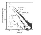
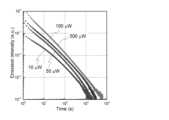
以上の発光メカニズムで蓄光体が発光することは、蓄光体に光を3分間照射した後に、光照射を停止し、その後の発光強度の経時変化を、縦軸に発光強度の対数をとり、横軸に経過時間の対数をとって両対数グラフとし、その両対数グラフが直線関係であることをもって確認することができる。ここで、蓄光体に照射する励起光には電子アクセプター分子の吸収波長または電子ドナー分子の吸収波長に一致する波長の光を用いることができる。
なお、有機化合物のフォトルミネッセンスによる通常の燐光では、縦軸に発光強度の対数をとり、横軸に時間(対数ではない通常の時間)をとってプロットした片対数グラフが直線(1次減衰)になることが確認されている。これに対して、本発明の蓄光体からの発光では、この片対数グラフは直線にならず、通常の燐光とは発光メカニズムが明らかに相違する。
以上、本発明の蓄光体の発光メカニズムについて説明したが、本発明の蓄光体は、上記の過程以外の過程で発光を生じてもよい。例えば、蓄光体に光が照射されたとき、図1下図に示すように、電子ドナー分子が光を吸収して、そのHOMOからLUMOへ電子遷移し[1]、電子アクセプター分子のLUMOへ電子が移動し[2]、電荷分離状態が生成してもよい。このように、HOMOからLUMOへの光吸収による電子遷移が電子アクセプター分子で起きるか電子ドナー分子で起きるかは、電子ドナー分子と電子アクセプター分子の存在比と、これら分子の吸収波長に依存する。すなわち、電子ドナー分子の存在比が比較的大きい場合や、電子ドナー分子の吸収波長が電子アクセプター分子の吸収波長よりも照射光の波長に近い場合には、電子ドナー分子のLUMOから電子アクセプター分子のLUMOへ電子が移動する経路で電荷分離状態が生成し易い傾向がある。
また、電荷分離状態が生成した後、電子ドナー分子に生じたホールが、隣接する電子ドナー分子のHOMOへ順次移動して拡散してもよい。この場合、拡散したホールが電子ドナー分子存在領域と電子アクセプター分子存在領域の界面で電子アクセプター分子の電子と再結合し、エネルギーが発生する。その再結合エネルギーにより、上記の[4]以降の発光メカニズムで発光が生じる。ホールが拡散する態様では、電子は拡散せず、ホールのみが拡散してもよく、電子とホールの両方が拡散してもよい。ただし、本発明の蓄光体では、ホールのみが拡散するよりも、電子のみが拡散するか、電子とホールの両方が拡散することが好ましい。
電子ドナー分子と電子アクセプター分子の存在比(モル比)は、特に制限されないが、電子アクセプター分子の存在比の方が電子ドナー分子の存在比よりも大きいことが好ましい。これにより、電子アクセプター分子のLUMOからLUMOに亘って電子が移動し易く、電子とホールの再結合を高い確率で発生させることができる。蓄光体における電子ドナー分子の含有量については、電子ドナー分子の含有量の項で具体的に説明する。 The presumed light-emitting mechanism of this phosphorescent body will be described below with reference to Fig. 1. Note that the numbers in square brackets in the following description correspond to the numbers in square brackets in Fig. 1 and indicate the order of each light-emitting process. Also, Fig. 1 shows specific structural formulas of the electron donor molecule and the electron acceptor molecule, but the electron donor molecule and the electron acceptor molecule represented by these structural formulas are only examples, and the electron donor molecule and the electron acceptor molecule that can be used in the present invention should not be interpreted as being limited by these specific examples.
As shown in the upper diagram of Figure 1, when light is irradiated onto this phosphorescent material, the electron acceptor molecule absorbs the light and electrons transition from its HOMO (Highest Occupied Molecular Orbital) to its LUMO (Lowest Unoccupied Molecular Orbital) [1], and electrons move from the HOMO of the electron donor molecule to the HOMO of the electron acceptor molecule [2]. This creates a charge-separated state consisting of an electron donor molecule in a radical cation state and an electron acceptor molecule in a radical anion state. The electrons that transition to the LUMO of the electron acceptor molecule move sequentially to the LUMO of the adjacent electron acceptor molecule and diffuse [3]. When the diffused electrons reach the interface between the electron donor molecule and the electron acceptor molecule, they recombine with the holes in the electron donor molecule present at the interface [4], which generates energy. The recombination energy causes, for example, the electron donor molecule and the electron acceptor molecule to associate to form an exciplex (excited state) [5]. At this time, the occurrence probability of the excited singlet state S1 and the excited triplet state T1 is 25%:75%, and fluorescence is emitted when the excited singlet state S1 returns to the ground state, and phosphorescence is emitted when the excited triplet state T1 returns to the ground state. Alternatively, reverse intersystem crossing occurs from the excited triplet state T1 to the excited singlet state S1 , and fluorescence is emitted when the excited singlet state S1 returns to the ground state. The fluorescence emitted through this reverse intersystem crossing is observed later than the fluorescence from the excited singlet state S1 that has transitioned directly from the ground state, and is referred to as "delayed fluorescence" in this specification.
Here, in the exciplex formed by the electron donor molecule and the electron acceptor molecule, the electron donor molecule and the electron acceptor molecule are spatially separated, so that the difference ΔEST between the lowest excited singlet energy level and the lowest excited triplet energy level can be made extremely small compared to when the electron donor and the electron acceptor are present in one molecule. As a result, the reverse intersystem crossing occurs with a high probability, and the energy of the excited triplet state T1 can also be effectively used for fluorescent emission. Therefore, high luminous efficiency can be obtained. In addition, in the present invention, since the radical cation state of the electron donor molecule and the radical anion state of the electron acceptor molecule generated in the above process [2] are stable, it is presumed that the electron donor molecule in the radical cation state and the electron acceptor molecule in the radical anion state are efficiently accumulated during light irradiation. Therefore, even after the light irradiation is stopped, the luminous mechanism from the above [4] onwards works, and this phosphorescent body can continue to emit light for a long time.
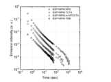
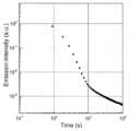
The fact that the phosphorescent body emits light through the above-mentioned light emission mechanism can be confirmed by irradiating the phosphorescent body with light for 3 minutes, stopping the light irradiation, plotting the change in the emission intensity over time thereafter with a logarithmic graph of the emission intensity on the vertical axis and the logarithm of the elapsed time on the horizontal axis, and seeing that the logarithmic graph shows a linear relationship. Here, the excitation light irradiated to the phosphorescent body can be light with a wavelength that matches the absorption wavelength of the electron acceptor molecule or the absorption wavelength of the electron donor molecule.
In addition, it has been confirmed that in normal phosphorescence due to photoluminescence of organic compounds, a semi-logarithmic graph plotted with the logarithm of luminous intensity on the vertical axis and time (normal time that is not logarithmic) on the horizontal axis becomes a straight line (first-order decay). In contrast, the light emitted from the phosphorescent body of the present invention does not become a straight line in this semi-logarithmic graph, and the light emission mechanism is clearly different from that of normal phosphorescence.
The light emitting mechanism of the phosphorescent body of the present invention has been described above, but the phosphorescent body of the present invention may emit light in a process other than the above process. For example, when light is irradiated to the phosphorescent body, as shown in the lower diagram of FIG. 1, the electron donor molecule absorbs the light, undergoes electronic transition from its HOMO to LUMO [1], and electrons move to the LUMO of the electron acceptor molecule [2], and a charge separation state may be generated. In this way, whether the electronic transition due to light absorption from HOMO to LUMO occurs in the electron acceptor molecule or the electron donor molecule depends on the abundance ratio of the electron donor molecule and the electron acceptor molecule and the absorption wavelength of these molecules. That is, when the abundance ratio of the electron donor molecule is relatively large or the absorption wavelength of the electron donor molecule is closer to the wavelength of the irradiated light than the absorption wavelength of the electron acceptor molecule, a charge separation state tends to be easily generated in the path in which electrons move from the LUMO of the electron donor molecule to the LUMO of the electron acceptor molecule.
In addition, after the charge separation state is generated, the holes generated in the electron donor molecule may be sequentially transferred to the HOMO of the adjacent electron donor molecule and diffused. In this case, the diffused holes recombine with the electrons of the electron acceptor molecule at the interface between the electron donor molecule presence region and the electron acceptor molecule presence region, generating energy. The recombination energy causes light emission in the light emission mechanism from [4] onwards. In the embodiment in which the holes diffuse, the electrons do not diffuse, and only the holes may diffuse, or both the electrons and the holes may diffuse. However, in the phosphorescent body of the present invention, it is preferable that only the electrons diffuse or both the electrons and the holes diffuse, rather than only the holes diffuse.
The abundance ratio (molar ratio) of the electron donor molecule and the electron acceptor molecule is not particularly limited, but it is preferable that the abundance ratio of the electron acceptor molecule is greater than that of the electron donor molecule. This makes it easier for electrons to move from LUMO to LUMO of the electron acceptor molecule, and allows the recombination of electrons and holes to occur with a high probability. The content of the electron donor molecule in the phosphorescent body will be specifically described in the section on the content of the electron donor molecule.
このように、本発明の蓄光体はラジカルカチオン状態が安定な電子ドナー分子とラジカルアニオン状態が安定な電子アクセプター分子を用いて残光を得るものであり、希土類元素を含む無機塩を用いずに、電子ドナー分子および電子アクセプター分子として有機化合物を用いることで実現することができる。このため、この蓄光体は、安価な有機化合物を原料に用いて簡単な工程で製造することができるとともに、電子アクセプター分子と電子ドナー分子の分子設計により、励起波長や発光波長、発光時間を容易に制御することができる。さらに、有機化合物は、透明性を確保しやすく、また、多くの有機溶媒に可溶であり、それらを均一に含む塗料を得ることができるため、この蓄光体からなる均一な蓄光膜を良好なパターンで形成することができる。
以下において、この蓄光体が含む電子アクセプター分子および電子ドナー分子、必要に応じて添加されるその他の成分について説明する。 In this way, the phosphorescent material of the present invention obtains afterglow using electron donor molecules with a stable radical cation state and electron acceptor molecules with a stable radical anion state, and can be realized by using organic compounds as the electron donor molecules and electron acceptor molecules without using inorganic salts containing rare earth elements. Therefore, this phosphorescent material can be manufactured in a simple process using inexpensive organic compounds as raw materials, and the excitation wavelength, emission wavelength, and emission time can be easily controlled by molecular design of the electron acceptor molecules and electron donor molecules. Furthermore, organic compounds are easy to ensure transparency, are soluble in many organic solvents, and can be used to obtain paints that uniformly contain them, so that a uniform phosphorescent film made of this phosphorescent material can be formed in a good pattern.
The electron acceptor molecule and electron donor molecule contained in the phosphorescent material, as well as other components that may be added as necessary, will be described below.
(電子アクセプター分子)
本発明の蓄光体を構成する電子アクセプター分子は、ラジカルアニオン状態が安定であり、電子ドナー分子と組み合わることにより10Kで残光放射を実現しうるものである。例えば、10Kで(および好ましくは20℃においても)電子ドナー分子とエキサイプレックスを形成して発光するものを選択することができる。電子アクセプター分子のHOMOとLUMOのギャップは1.0~3.5eVであることが好ましく、1.5~3.4eVであることがより好ましく、2.0~3.3eVであることがさらに好ましい。これにより、蓄光体への光照射に伴って、そのHOMOからLUMOへの電子遷移を効率よく生じさせることができる。また、電子アクセプター分子のLUMOは6.0eV以下であることが好ましく、5.5eV以下あることがより好ましく、5.0eV以下であることがさらに好ましい。これにより、電荷分離状態が生成した後、電子アクセプター分子のLUMOからLUMOに亘って電子が移動し易く、ホールとの再結合を高い確率で発生させることができる。
電子アクセプター分子のHOMOは光電子分光法またはサイクリックボルタンメトリーにより測定することができ、またLUMOはサイクリックボルタンメトリーまたは吸収スペクトルより求めることが出来る。
また、電子アクセプター分子は、室温においてガラス状態で存在しうるように、高いガラス転移温度Tgを有するものであることが好ましく、また、成膜したときに高い膜密度が得られるものであることが好ましい。膜における電子アクセプターの密度が高いことにより、電荷分離状態が生成した後、電子アクセプター分子のLUMOからLUMOに亘って電子が拡散し易く、電子とホールの再結合を高い確率で発生させることができる。(Electron acceptor molecule)
The electron acceptor molecule constituting the phosphorescent material of the present invention has a stable radical anion state, and can realize afterglow emission at 10K by combining with an electron donor molecule. For example, one that forms an exciplex with an electron donor molecule and emits light at 10K (and preferably at 20°C) can be selected. The gap between the HOMO and LUMO of the electron acceptor molecule is preferably 1.0 to 3.5 eV, more preferably 1.5 to 3.4 eV, and even more preferably 2.0 to 3.3 eV. This allows efficient electron transition from the HOMO to the LUMO when the phosphorescent material is irradiated with light. In addition, the LUMO of the electron acceptor molecule is preferably 6.0 eV or less, more preferably 5.5 eV or less, and even more preferably 5.0 eV or less. As a result, after the charge separation state is generated, electrons can easily move from LUMO to LUMO of the electron acceptor molecule, and recombination with holes can occur with a high probability.
The HOMO of the electron acceptor molecule can be measured by photoelectron spectroscopy or cyclic voltammetry, and the LUMO can be determined by cyclic voltammetry or absorption spectroscopy.
In addition, the electron acceptor molecule preferably has a high glass transition temperature Tg so that it can exist in a glassy state at room temperature, and preferably has a high film density when formed into a film. Due to the high density of the electron acceptor in the film, after the charge separation state is generated, the electrons are easily diffused from LUMO to LUMO of the electron acceptor molecule, and the recombination of electrons and holes can occur with a high probability.
電子アクセプター分子には、ラジカルアニオンの安定性の点から、電気陰性度が高い原子や電子求引基を有する化合物を用いることが好ましく、電気陰性度が高い原子や電子求引基と共役系を有する化合物を用いることがより好ましい。From the standpoint of the stability of the radical anion, it is preferable to use a compound having a highly electronegative atom or an electron-withdrawing group as the electron acceptor molecule, and it is even more preferable to use a compound having a conjugated system with a highly electronegative atom or an electron-withdrawing group.
電子アクセプター分子の好ましい例として、ホスフィンオキシド構造R3P(=O)(Rは置換基を表し、3つのR同士は、互いに同一であっても異なっていてもよい)を1つ以上含む化合物を挙げることができ、さらに好ましい例として、ホスフィンオキシド構造R3P(=O)を1つ以上と、それ以外にヘテロ原子を1つ以上含む化合物を挙げることができる。ヘテロ原子としては、N、O、S、P等を挙げることができ、このうちの1種のみを含んでいてもよいし、2種以上を含んでいてもよい。電子アクセプター分子が含むホスフィンオキシド構造の数は2つ以上であることが好ましく、その場合、複数のホスフィンオキシド構造は互いに同一であっても異なっていてもよい。また、複数のホスフィンオキシド構造は、その置換基Rの少なくとも1つが他のホスフィンオキシド構造の置換基Rにヘテロ原子を介して連結していることが好ましく、その置換基Rの少なくとも1つが他のホスフィンオキシド構造の置換基Rにヘテロ原子を介して連結するとともに、その連結している置換基Rのヘテロ原子に結合している原子とは別の原子同士が互いに単結合で連結していることがより好ましい。
ホスフィンオキシド構造の置換基Rは、置換もしくは無置換のアリール基、置換もしくは無置換のヘテロアリール基であることが好ましい。アリール基を構成する芳香環の説明と好ましい範囲、アリール基の具体例については、下記のAr11等が置換もしくは無置換のアリール基であるときのアリール基を構成する芳香環についての説明と好ましい範囲、アリール基の具体例を参照することができる。ヘテロアリール基を構成する複素環の説明と好ましい範囲、ヘテロアリール基の具体例については、下記のAr11等が置換もしくは無置換のヘテロアリール基であるときのヘテロアリール基を構成する複素環についての説明と好ましい範囲、ヘテロアリール基の具体例を参照することができる。アリール基およびヘテロアリール基に置換しうる置換基の具体例と好ましい範囲については、Ar11等におけるアリール基およびヘテロアリール基に置換しうる置換基の具体例と好ましい範囲を参照することができる。 A preferred example of the electron acceptor molecule is a compound containing one or more phosphine oxide structures R3 P(═O) (R represents a substituent, and the three Rs may be the same or different from each other), and a more preferred example is a compound containing one or more phosphine oxide structures R3 P(═O) and one or more heteroatoms in addition to the above. Examples of the heteroatom include N, O, S, P, etc., and the compound may contain only one of these, or may contain two or more of them. The number of phosphine oxide structures contained in the electron acceptor molecule is preferably two or more, and in this case, the multiple phosphine oxide structures may be the same or different from each other. In addition, in the multiple phosphine oxide structures, at least one of the substituents R is preferably linked to a substituent R of another phosphine oxide structure via a heteroatom, and it is more preferable that at least one of the substituents R is linked to a substituent R of another phosphine oxide structure via a heteroatom, and atoms other than the atom bonded to the heteroatom of the linked substituent R are linked to each other via a single bond.
The substituent R of the phosphine oxide structure is preferably a substituted or unsubstituted aryl group or a substituted or unsubstituted heteroaryl group. For the explanation and preferred range of the aromatic ring constituting the aryl group and specific examples of the aryl group, the explanation and preferred range of the aromatic ring constituting the aryl group when Ar11 or the like is a substituted or unsubstituted aryl group below and specific examples of the aryl group can be referred to. For the explanation and preferred range of the heterocyclic ring constituting the heteroaryl group and specific examples of the heteroaryl group, the explanation and preferred range of the heterocyclic ring constituting the heteroaryl group when Ar11 or the like is a substituted or unsubstituted heteroaryl group below and specific examples of the heteroaryl group can be referred to. For the specific examples and preferred range of the substituents that can be substituted on the aryl group and the heteroaryl group, the specific examples and preferred range of the substituents that can be substituted on the aryl group and the heteroaryl group in Ar11 or the like can be referred to.
電子アクセプター分子は、下記一般式(1)で表される化合物であることが好ましい。
一般式(1)において、Ar11~Ar14は各々独立に置換もしくは無置換のアリール基または置換もしくは無置換のヘテロアリール基を表し、置換もしくは無置換のアリール基であることが好ましい。Ar11~Ar14は互いに同一であっても異なっていてもよい。Ar15およびAr16は各々独立に置換もしくは無置換のアリーレン基または置換もしくは無置換のヘテロアリーレン基を表し、Ar15とAr16は互いに単結合で連結して縮環構造を形成していてもよい。Ar15およびAr16は互いに同一であっても異なっていてもよい。Ar15およびAr16は置換もしくは無置換のアリーレン基であることが好ましく、そのアリーレン基同士が、互いに単結合で連結して縮環構造を形成していることがより好ましい。 In the general formula (1), Ar11 to Ar14 each independently represent a substituted or unsubstituted aryl group or a substituted or unsubstituted heteroaryl group, and are preferably substituted or unsubstituted aryl groups. Ar11 to Ar14 may be the same or different from each other. Ar15 and Ar16 each independently represent a substituted or unsubstituted arylene group or a substituted or unsubstituted heteroarylene group, and Ar15 and Ar16 may be linked to each other by a single bond to form a condensed ring structure. Ar15 and Ar16 may be the same or different from each other. Ar15 and Ar16 are preferably substituted or unsubstituted arylene groups, and it is more preferable that the arylene groups are linked to each other by a single bond to form a condensed ring structure.
Ar11~Ar14が置換もしくは無置換のアリール基であるときのアリール基を構成する芳香環、並びに、Ar15およびAr16が置換もしくは無置換のアリーレン基であるときのアリーレン基を構成する芳香環は、単環であっても、2以上の芳香環が縮合した縮合環であっても、2以上の芳香環が連結した連結環であってもよい。2以上の芳香環が連結している場合は、直鎖状に連結したものであってもよいし、分枝状に連結したものであってもよい。アリール基およびアリーレン基を構成する芳香環の炭素数は、6~40であることが好ましく、6~22であることがより好ましく、6~18であることがさらに好ましく、6~14であることがさらにより好ましく、6~10であることが特に好ましい。アリール基の具体例として、フェニル基、ナフタレニル基、ビフェニル基を挙げることができる。アリーレン基の具体例として、フェニレン基、ナフタレンジイル基、ビフェニルジイル基を挙げることができる。これらの中で、Ar11~Ar14として特に好ましいのは、置換もしくは無置換のフェニル基である。また、Ar15およびAr16として特に好ましいのは、置換もしくは無置換のフェニレン基であり、そのフェニレン基同士が互いに単結合で連結して3環構造(ベンゼン環とX11を含む5員環とベンゼン環の3環構造)を形成していることが特により好ましい。 The aromatic rings constituting the aryl group when Ar11 to Ar14 are substituted or unsubstituted aryl groups, and the aromatic rings constituting the arylene group when Ar15 and Ar16 are substituted or unsubstituted arylene groups, may be a single ring, a condensed ring in which two or more aromatic rings are condensed, or a linked ring in which two or more aromatic rings are linked. When two or more aromatic rings are linked, they may be linked in a straight chain or in a branched chain. The number of carbon atoms in the aromatic rings constituting the aryl group and the arylene group is preferably 6 to 40, more preferably 6 to 22, even more preferably 6 to 18, even more preferably 6 to 14, and particularly preferably 6 to 10. Specific examples of the aryl group include a phenyl group, a naphthalenyl group, and a biphenyl group. Specific examples of the arylene group include a phenylene group, a naphthalenediyl group, and a biphenyldiyl group. Among these, substituted or unsubstituted phenyl groups are particularly preferred as Ar11 to Ar14. Also, substituted or unsubstituted phenylene groups are particularly preferred as Ar15 and Ar16 , and it is particularly preferred that the phenylene groups are linked to each other via single bonds to form a three-ring structure (a three-ring structure of a benzene ring, a five-membered ring containing X11 , and a benzene ring).
Ar11~Ar14が置換もしくは無置換のヘテロアリール基であるときのヘテロアリール基を構成する複素環、並びに、Ar15およびAr16が置換もしくは無置換のヘテロアリーレン基であるときのヘテロアリーレン基を構成する複素環は、単環であっても、1以上の複素環と芳香環または複素環が縮合した縮合環であっても、1以上の複素環と芳香環または複素環が連結した連結環であってもよい。ヘテロアリール基を構成する複素環の炭素数は3~40であることが好ましく、5~22であることがより好ましく、5~18であることがさらに好ましく、5~14であることがさらにより好ましく、5~10であることが特に好ましい。複素環を構成する複素原子は窒素原子であることが好ましい。複素環の具体例として、ピリジン環、ピリダジン環、ピリミジン環、トリアゾール環、ベンゾトリアゾール環を挙げることができる。 The heterocyclic ring constituting the heteroaryl group when Ar11 to Ar14 are substituted or unsubstituted heteroaryl groups, and the heterocyclic ring constituting the heteroarylene group when Ar15 and Ar16 are substituted or unsubstituted heteroarylene groups, may be a monocyclic ring, a condensed ring in which one or more heterocyclic rings are condensed with an aromatic ring or a heterocyclic ring, or a linked ring in which one or more heterocyclic rings are linked with an aromatic ring or a heterocyclic ring. The number of carbon atoms in the heterocyclic ring constituting the heteroaryl group is preferably 3 to 40, more preferably 5 to 22, even more preferably 5 to 18, even more preferably 5 to 14, and particularly preferably 5 to 10. The heteroatom constituting the heterocyclic ring is preferably a nitrogen atom. Specific examples of the heterocyclic ring include a pyridine ring, a pyridazine ring, a pyrimidine ring, a triazole ring, and a benzotriazole ring.
Ar11~Ar14におけるアリール基およびヘテロアリール基に置換しうる置換基、Ar15およびAr16におけるアリーレン基およびヘテロアリーレン基に置換しうる置換基として、例えばヒドロキシ基、ハロゲン原子、炭素数1~20のアルキル基、炭素数1~20のアルコキシ基、炭素数1~20のアルキルチオ基、炭素数1~20のアルキル置換アミノ基、炭素数1~20のアリール置換アミノ基、炭素数6~40のアリール基、炭素数3~40のヘテロアリール基、炭素数2~10のアルケニル基、炭素数2~10のアルキニル基、炭素数2~20のアルキルアミド基、炭素数7~21のアリールアミド基、炭素数3~20のトリアルキルシリル基等が挙げられる。これらの具体例のうち、さらに置換基により置換可能なものは置換されていてもよい。より好ましい置換基は、炭素数1~20のアルキル基、炭素数1~20のアルコキシ基、炭素数1~20のアルキルチオ基、炭素数1~20のアルキル置換アミノ基、炭素数1~20のアリール置換アミノ基、炭素数6~40のアリール基、炭素数3~40のヘテロアリール基である。 Examples of the substituents which may be substituted on the aryl and heteroaryl groups in Ar11 to Ar14 , and the substituents which may be substituted on the arylene and heteroarylene groups in Ar15 and Ar16 include a hydroxy group, a halogen atom, an alkyl group having 1 to 20 carbon atoms, an alkoxy group having 1 to 20 carbon atoms, an alkylthio group having 1 to 20 carbon atoms, an alkyl-substituted amino group having 1 to 20 carbon atoms, an aryl-substituted amino group having 1 to 20 carbon atoms, an aryl group having 6 to 40 carbon atoms, a heteroaryl group having 3 to 40 carbon atoms, an alkenyl group having 2 to 10 carbon atoms, an alkynyl group having 2 to 10 carbon atoms, an alkylamide group having 2 to 20 carbon atoms, an arylamide group having 7 to 21 carbon atoms, a trialkylsilyl group having 3 to 20 carbon atoms, etc. Among these specific examples, those which may be further substituted by a substituent may be substituted. More preferred substituents are an alkyl group having 1 to 20 carbon atoms, an alkoxy group having 1 to 20 carbon atoms, an alkylthio group having 1 to 20 carbon atoms, an alkyl-substituted amino group having 1 to 20 carbon atoms, an aryl-substituted amino group having 1 to 20 carbon atoms, an aryl group having 6 to 40 carbon atoms, and a heteroaryl group having 3 to 40 carbon atoms.
X11はNR11、OまたはSを表し、R11は水素原子または置換基を表す。R11がとりうる置換基として、例えば炭素数1~20のアルキル基、炭素数6~40のアリール基、炭素数3~40のヘテロアリール基、炭素数2~10のアルケニル基、炭素数2~10のアルキニル基等を挙げることができる。これらの置換基は、さらに置換基で置換されていてもよい。R11は、水素原子、置換もしくは無置換のアリール基であることが好ましく、置換もしくは無置換のアリール基であることがより好ましく、置換もしくは無置換のフェニル基であることがさらに好ましい。 X11 represents NR11 , O or S, and R11 represents a hydrogen atom or a substituent. Examples of the substituent that R11 may have include an alkyl group having 1 to 20 carbon atoms, an aryl group having 6 to 40 carbon atoms, a heteroaryl group having 3 to 40 carbon atoms, an alkenyl group having 2 to 10 carbon atoms, and an alkynyl group having 2 to 10 carbon atoms. These substituents may be further substituted with a substituent. R11 is preferably a hydrogen atom or a substituted or unsubstituted aryl group, more preferably a substituted or unsubstituted aryl group, and even more preferably a substituted or unsubstituted phenyl group.
また、本発明で用いる電子アクセプター分子は、下記のいずれかの部分構造を有する化合物であることも好ましい。下記部分構造におけるArは芳香環または複素芳香環を表し、融合環であってもよい。下記部分構造において置換可能な水素原子は、置換されていてもよい。また、これらの部分構造や、電子アクセプター分子に重合性基を導入し、これをモノマーとして重合した重合体であってもよいし、非重合体であってもよい。重合体を採用する場合の繰り返し単位数nは2以上とすることができ、例えば4以上、6以上、8以上、10以上にすることも可能である。重合体を採用する場合の分子量は例えば1000以上、2000以上、5000以上、10000以上にすることも可能である。重合体を採用することにより、蓄光寿命をより長くすることが可能である。
ジフェニルホスフィン部分構造を含む電子アクセプター分子の一般式として、下記一般式(2)および一般式(3)を挙げることができる。
一般式(2)および一般式(3)において、L1は2価の連結基を表し、好ましくは置換もしくは無置換のアルキレン基、置換もしくは無置換のアリーレン基、置換もしくは無置換のヘテロアリーレン基、ヘテロ原子で連結する置換基を有していてもよい基、あるいは、これらの連結基の2種以上が連結した基を挙げることができる。R1~R34は各々独立に水素原子または置換基を表し、好ましくは水素原子、置換もしくは無置換のアルキル基、置換もしくは無置換のアルコキシ基、置換もしくは無置換のアリール基、置換もしくは無置換のヘテロアリール基を挙げることができる。ここでいう置換アルキル基や置換アルコキシ基には、ポリアルキレンオキシ構造を持つものも含まれる。
以下に一般式(2)および一般式(3)におけるL1の好ましい具体例を挙げるが、本発明で採用することができる基は以下の具体例に限定されることはない。なお、nは1以上の整数を表す。 In general formula (2) and general formula (3), L1 represents a divalent linking group, preferably a substituted or unsubstituted alkylene group, a substituted or unsubstituted arylene group, a substituted or unsubstituted heteroarylene group, a group which may have a substituent linked by a heteroatom, or a group in which two or more of these linking groups are linked. R1 to R34 each independently represent a hydrogen atom or a substituent, preferably a hydrogen atom, a substituted or unsubstituted alkyl group, a substituted or unsubstituted alkoxy group, a substituted or unsubstituted aryl group, or a substituted or unsubstituted heteroaryl group. The substituted alkyl group and substituted alkoxy group referred to here also include those having a polyalkyleneoxy structure.
Preferred specific examples ofL1 in formula (2) and formula (3) are given below, but the groups that can be used in the present invention are not limited to the following specific examples. Here, n represents an integer of 1 or more.


L2~L4は、1または2原子を介して連結する連結基であり、好ましくは1原子を介して連結する連結基である。例えば好ましい連結基として下記の連結基を挙げることができる。
以下に一般式(2)および一般式(3)におけるR1~R34の好ましい具体例を挙げるが、本発明で採用することができる基は以下の具体例に限定されることはない。
ジフェニルホスフィン部分構造を有する電子アクセプター分子の具体例を以下に挙げる。なお、以下の具体例におけるRはアルキル基またはフェニル基を表し、mおよびnは各々独立に2以上の整数を表す。
以下において、電子アクセプター分子として用いることができる、上記以外の好ましい化合物を挙げる。好ましい化合物には、後述する実施例で採用している具体的な電子アクセプター分子も含まれる。ただし、本発明において用いることができる電子アクセプター分子はこれらの具体例によって限定的に解釈されるべきものではない。Below, other preferred compounds that can be used as electron acceptor molecules are listed. The preferred compounds also include the specific electron acceptor molecules used in the examples described below. However, the electron acceptor molecules that can be used in the present invention should not be interpreted as being limited to these specific examples.


(電子ドナー分子)
蓄光体を構成する電子ドナー分子は、ラジカルカチオン状態が安定であり、電子アクセプター分子と組み合わることにより10Kで残光放射を実現しうるものである。例えば、10Kで(および好ましくは20℃においても)電子アクセプター分子とエキサイプレックスを形成して発光するものを選択することができる。電子ドナー分子のHOMOは電子アクセプター分子のHOMOよりも高く、そのLUMOが電子アクセプター分子のLUMOよりも高いことが好ましい。これにより、電子ドナー分子のHOMOから電子アクセプター分子のHOMOまたはLUMOへの電子移動が生じ易くなり、電荷分離状態を効率よく生成することができる。具体的には、電子ドナー分子のHOMOは、-3.5~-8.0eVであることが好ましく、-4.0~-7.0eVであることがより好ましく、-4.5~-6.0eVであることがさらに好ましい。
電子ドナー分子のHOMOおよびLUMOはHOMOは光電子分光法またはサイクリックボルタンメトリーにより測定することができ、またLUMOはサイクリックボルタンメトリーまたは吸収スペクトルより求めることが出来る。(Electron donor molecule)
The electron donor molecule constituting the phosphorescent body has a stable radical cation state, and can realize afterglow emission at 10K by combining with an electron acceptor molecule. For example, one that forms an exciplex with an electron acceptor molecule and emits light at 10K (and preferably at 20°C) can be selected. The HOMO of the electron donor molecule is preferably higher than the HOMO of the electron acceptor molecule, and the LUMO of the electron donor molecule is preferably higher than the LUMO of the electron acceptor molecule. This makes it easier for electrons to move from the HOMO of the electron donor molecule to the HOMO or LUMO of the electron acceptor molecule, and allows the charge separation state to be efficiently generated. Specifically, the HOMO of the electron donor molecule is preferably -3.5 to -8.0 eV, more preferably -4.0 to -7.0 eV, and even more preferably -4.5 to -6.0 eV.
The HOMO and LUMO of the electron donor molecule can be measured by photoelectron spectroscopy or cyclic voltammetry, and the LUMO can be determined by cyclic voltammetry or absorption spectroscopy.
電子ドナー分子には、ラジカルカチオンの安定性の点から、電子供与基を有する化合物を用いることが好ましく、電子供与基と共役系を有する化合物を用いることがより好ましく、ジアルキルアミノ基と芳香環を有する化合物やジフェニルアミノ基を有する化合物(ジフェニルアミノ基を構成する2つのフェニル基が互いに結合している化合物も含む)を用いることがさらに好ましい。From the viewpoint of the stability of the radical cation, it is preferable to use a compound having an electron-donating group as the electron donor molecule, it is more preferable to use a compound having an electron-donating group and a conjugated system, and it is even more preferable to use a compound having a dialkylamino group and an aromatic ring or a compound having a diphenylamino group (including a compound in which the two phenyl groups constituting the diphenylamino group are bonded to each other).
電子ドナー分子がジアルキルアミノ基と芳香環を有する化合物である場合、その芳香環は、芳香族炭化水素であってもよいし、芳香族複素環であってもよいが、芳香族炭化水素であることが好ましい。芳香族炭化水素の説明と好ましい範囲については、上記のAr15およびAr16が置換もしくは無置換のアリーレン基であるときのアリーレン基を構成する芳香環についての説明と好ましい範囲を参照することができる。また、芳香族複素環の説明と好ましい範囲については、上記のAr15およびAr16が置換もしくは無置換のヘテロアリーレン基であるときのヘテロアリーレン基を構成する複素環についての説明と好ましい範囲を参照することができる。これらの中で、芳香環はベンゼン環、ビフェニル環であることが好ましく、ビフェニル環であることがより好ましい。芳香環は置換基で置換されていてもよい。芳香環に置換しうる置換基の具体例と好ましい範囲については、上記のAr15およびAr16におけるアリーレン基等に置換しうる置換基の具体例と好ましい範囲を参照することができる。一方、ジアルキルアミノ基は芳香環に置換していることが好ましい。電子ドナー分子が含むジアルキルアミノ基の数は、1つであってもよいし、2つ以上であってもよいが、1~4つであることが好ましく、2つまたは4つであることがより好ましく、2つであることがさらに好ましい。ジアルキルアミノ基のアルキル基の説明と好ましい範囲、具体例については、下記のR21等におけるアルキル基についての説明と好ましい範囲、具体例を参照することができる。ジアルキルアミノ基のアルキル基は置換基で置換されていてもよい。その置換基の説明と好ましい範囲については、R21等におけるアルキル基に置換しうる置換基についての説明と好ましい範囲を参照することができる。 When the electron donor molecule is a compound having a dialkylamino group and an aromatic ring, the aromatic ring may be an aromatic hydrocarbon or an aromatic heterocycle, but is preferably an aromatic hydrocarbon. For the description and preferred range of the aromatic hydrocarbon, the description and preferred range of the aromatic ring constituting the arylene group when Ar15 and Ar16 are substituted or unsubstituted arylene groups can be referred to. For the description and preferred range of the aromatic heterocycle, the description and preferred range of the heterocycle constituting the heteroarylene group when Ar15 and Ar16 are substituted or unsubstituted heteroarylene groups can be referred to. Among these, the aromatic ring is preferably a benzene ring or a biphenyl ring, and more preferably a biphenyl ring. The aromatic ring may be substituted with a substituent. For the specific examples and preferred range of the substituent that can be substituted on the aromatic ring, the specific examples and preferred range of the substituent that can be substituted on the arylene group in Ar15 and Ar16 can be referred to. On the other hand, it is preferable that the dialkylamino group is substituted on the aromatic ring. The number of dialkylamino groups contained in the electron donor molecule may be one or two or more, but is preferably one to four, more preferably two or four, and even more preferably two. For the explanation, preferred range, and specific examples of the alkyl group of the dialkylamino group, the explanation, preferred range, and specific examples of the alkyl group in R21 etc. below can be referred to. The alkyl group of the dialkylamino group may be substituted with a substituent. For the explanation and preferred range of the substituent, the explanation and preferred range of the substituent that can be substituted for the alkyl group in R21 etc. can be referred to.
電子ドナー分子は、下記一般式(4)で表される化合物であることが好ましい。
一般式(4)において、Ar21は置換もしくは無置換のアリーレン基を表す。Ar21のアリーレン基を構成する芳香環の説明と好ましい範囲、アリーレン基の具体例については、上記のAr15およびAr16が置換もしくは無置換のアリーレン基であるときのアリーレン基を構成する芳香環についての説明と好ましい範囲、アリーレン基の具体例を参照することができる。Ar21は置換もしくは無置換のフェニレン基、置換もしくは無置換のビフェニルジイル基であることが好ましく、置換もしくは無置換のビフェニルジイル基であることがより好ましい。アリーレン基に置換しうる置換基の具体例と好ましい範囲については、上記のAr15およびAr16におけるアリーレン基等に置換しうる置換基の具体例と好ましい範囲を参照することができる。 In the general formula (4), Ar21 represents a substituted or unsubstituted arylene group. For the description and preferred range of the aromatic ring constituting the arylene group of Ar21 , and specific examples of the arylene group, reference can be made to the description and preferred range of the aromatic ring constituting the arylene group when Ar15 and Ar16 are substituted or unsubstituted arylene groups, and specific examples of the arylene group. Ar21 is preferably a substituted or unsubstituted phenylene group, a substituted or unsubstituted biphenyldiyl group, and more preferably a substituted or unsubstituted biphenyldiyl group. For the specific examples and preferred range of the substituents that can be substituted on the arylene group, reference can be made to the specific examples and preferred range of the substituents that can be substituted on the arylene group in Ar15 and Ar16 .
R21~R24は各々独立に置換もしくは無置換のアルキル基を表す。R21~R24は互いに同一であっても異なっていてもよい。R21~R24におけるアルキル基は、直鎖状、分枝状、環状のいずれであってもよい。好ましい炭素数は1~20であり、より好ましくは1~10であり、さらに好ましくは1~6である。例えば、メチル基、エチル基、n-プロピル基、イソプロピル基などを例示することができる。アルキル基に置換しうる置換基として、炭素数6~40のアリール基、炭素数3~40のヘテロアリール基、炭素数2~10のアルケニル基、炭素数2~10のアルキニル基等を挙げることができる。これらの置換基は、さらに置換基で置換されていてもよい。 R21 to R24 each independently represent a substituted or unsubstituted alkyl group. R21 to R24 may be the same or different from each other. The alkyl group in R21 to R24 may be linear, branched, or cyclic. The number of carbon atoms is preferably 1 to 20, more preferably 1 to 10, and even more preferably 1 to 6. For example, methyl, ethyl, n-propyl, and isopropyl groups can be exemplified. Examples of substituents that can be substituted on the alkyl group include aryl groups having 6 to 40 carbon atoms, heteroaryl groups having 3 to 40 carbon atoms, alkenyl groups having 2 to 10 carbon atoms, and alkynyl groups having 2 to 10 carbon atoms. These substituents may be further substituted with a substituent.
以下において、電子ドナー分子として用いることができる好ましい化合物を挙げる。好ましい化合物には、後述する実施例で採用している具体的な電子ドナー分子も含まれる。ただし、本発明において用いることができる電子ドナー分子はこれらの具体例によって限定的に解釈されるべきものではない。Below, preferred compounds that can be used as electron donor molecules are listed. Preferred compounds also include the specific electron donor molecules used in the examples described below. However, the electron donor molecules that can be used in the present invention should not be interpreted as being limited to these specific examples.


また、本発明で用いる電子ドナー分子は、単体である電子ドナー分子に重合性基を導入し、これをモノマーとして重合した重合体であってもよい。電子ドナー分子として用いることができる重合体の具体例として、下記構造を有する重合体を挙げることができる。下記式において、nは1以上の整数である。ただし、本発明において電子ドナー分子として用いることができる重合体はこの具体例によって限定的に解釈されるべきものではない。The electron donor molecule used in the present invention may be a polymer obtained by introducing a polymerizable group into a simple electron donor molecule and polymerizing this as a monomer. Specific examples of polymers that can be used as electron donor molecules include polymers having the following structures. In the following formula, n is an integer of 1 or more. However, the polymers that can be used as electron donor molecules in the present invention should not be interpreted as being limited by these specific examples.

(電子ドナー分子の含有量)
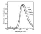
蓄光体における電子ドナー分子の含有量は、電子ドナー分子と電子アクセプター分子の合計モル数に対して60mol%未満であることが好ましく、30mol%未満であることがより好ましく、20mol%未満であることがさらに好ましく、10mol%未満であることがさらにより好ましい。また、蓄光体における電子ドナー分子の含有量は、電子ドナー分子と電子アクセプター分子の合計モル数に対して0.001mol%超であることが好ましく、0.01mol%超であることがより好ましく、1mol%超であることがさらに好ましい。電子ドナー分子の含有量を変えることにより、蓄光体が発光する発光色を制御することができる。例えば、電子ドナー分子の含有量を多くする程、エキサイプレックス形成が強くなり長波長の発光になるという現象が見られる。こうした現象を利用することで、蓄光体の発光色や発光時間を制御することができる。例えば、実施例で使用しているPO2CzPhを電子アクセプター分子として含み、TMBを電子ドナー分子として含む蓄光体では、TMBの含有量が30mol%未満である場合には青色光を観測することができ、TMBの含有量が30mol%超である場合には黄色光が観測される。(Content of electron donor molecules)
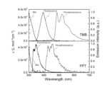
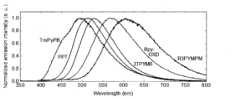
The content of the electron donor molecule in the phosphorescent body is preferably less than 60 mol% relative to the total mole number of the electron donor molecule and the electron acceptor molecule, more preferably less than 30 mol%, even more preferably less than 20 mol%, and even more preferably less than 10 mol%. The content of the electron donor molecule in the phosphorescent body is preferably more than 0.001 mol% relative to the total mole number of the electron donor molecule and the electron acceptor molecule, more preferably more than 0.01 mol%, and even more preferably more than 1 mol%. By changing the content of the electron donor molecule, the luminescent color emitted by the phosphorescent body can be controlled. For example, the phenomenon that the more the content of the electron donor molecule is increased, the stronger the exciplex formation and the longer the wavelength of the light emission is observed. By utilizing such a phenomenon, the luminescent color and the luminescent time of the phosphorescent body can be controlled. For example, in a phosphorescent material used in the examples that contains PO2CzPh as an electron acceptor molecule and TMB as an electron donor molecule, blue light can be observed when the TMB content is less than 30 mol%, and yellow light is observed when the TMB content is more than 30 mol%.
(その他の成分)
本発明の蓄光体は、電子アクセプター分子と電子ドナー分子のみから構成されていてもよいし、その他の成分が添加されていてもよいし、電子アクセプター分子および電子ドナー分子、その他の成分を溶解する溶媒を含んでいてもよい。その他の成分として、例えば蛍光材料、燐光材料や遅延蛍光を放射する発光材料(遅延蛍光材料)等の発光材料や、キャリアトラップ材料を挙げることができる。ここで、「遅延蛍光」とは、エネルギー供与により励起状態になった化合物において、励起三重項状態から励起一重項状態への逆項間交差が生じた後、その励起一重項状態から基底状態に戻る際に放射される蛍光であり、直接生じた励起一重項状態からの蛍光(通常の蛍光であり、前記遅延蛍光以外の蛍光)よりも遅れて観測される蛍光である。
蓄光体に蛍光材料を添加することにより、発光波長を制御することができる。
蓄光体に燐光材料を添加することにより、蓄光体が発光する燐光の割合を増加させることができ、燐光の割合を100%にすることもできる。
一方、蓄光体に遅延蛍光材料を添加した場合には、その遅延蛍光材料で励起三重項エネルギー状態から励起一重項エネルギー状態への逆項間交差が生じうるため、蓄光体が発光する蛍光の割合を増加させることができ、蛍光の割合を100%にすることもできる。
蓄光体に添加する燐光材料および遅延蛍光材料としては、公知のものを選択して用いることができる。
蓄光体に燐光材料や遅延蛍光材料を添加する場合、燐光材料および遅延蛍光材料の添加量は、それぞれ、蓄光体の全質量に対して50mol%未満であることが好ましく、25mol%未満であることがより好ましく、0.001~10mol%であることがさらに好ましい。
また、蓄光体にはキャリアトラップ材料を添加することもできる。キャリアトラップ材料を添加することにより、電荷分離により生じた電子アクセプター分子のラジカルカチオンからキャリアトラップ材料への電子移動がおき、キャリアトラップ材料中で電子をより安定に蓄積することができる。キャリアトラップ材料に蓄積された電子は熱などのエネルギーで再び電子アクセプター分子に戻り、電子ドナー材料の界面で再結合することで蓄光発光が得られる。
キャリアトラップ材料としては、そのLUMO準位が電子アクセプター分子のLUMO準位と近い材料が好ましい。キャリアトラップ材料のLUMO準位は、電子アクセプター分子のLUMO準位より0.001eV以上低いことが好ましく、0.01eV以上低いことがより好ましく、0.1eV以上低いことがさらに好ましい。また、キャリアトラップ材料のLUMO準位と、電子アクセプター分子のLUMO準位との差は、0.5eV以下であることが好ましく、0.4eV以下であることがより好ましく、0.3eV以下であることがさらに好ましい。(Other ingredients)
The phosphorescent body of the present invention may be composed of only electron acceptor molecules and electron donor molecules, or may contain other components added thereto, or may contain a solvent that dissolves electron acceptor molecules, electron donor molecules, and other components. Examples of other components include luminescent materials such as fluorescent materials, phosphorescent materials, and luminescent materials that emit delayed fluorescence (delayed fluorescent materials), and carrier trapping materials. Here, "delayed fluorescence" refers to the fluorescence emitted when a compound that has been excited by energy donation returns from an excited triplet state to an excited singlet state after reverse intersystem crossing occurs, and is observed later than the fluorescence from the directly generated excited singlet state (normal fluorescence, fluorescence other than the delayed fluorescence).
By adding a fluorescent material to the phosphorescent material, the emission wavelength can be controlled.
By adding a phosphorescent material to the phosphorescent body, the proportion of phosphorescence emitted by the phosphorescent body can be increased, and the proportion of phosphorescence can be made 100%.
On the other hand, when a delayed fluorescent material is added to the phosphorescent body, the delayed fluorescent material can undergo reverse intersystem crossing from an excited triplet energy state to an excited singlet energy state, thereby increasing the proportion of fluorescence emitted by the phosphorescent body, and making it possible to make the proportion of
The phosphorescent material and delayed fluorescent material to be added to the phosphorescent material may be selected from known materials.
When a phosphorescent material or a delayed fluorescent material is added to the phosphorescent body, the amount of the phosphorescent material and the delayed fluorescent material added is preferably less than 50 mol %, more preferably less than 25 mol %, and even more preferably 0.001 to 10 mol %, based on the total mass of the phosphorescent body.
A carrier trapping material can also be added to the phosphorescent body. By adding a carrier trapping material, electrons are transferred from the radical cations of the electron acceptor molecules generated by charge separation to the carrier trapping material, allowing electrons to be stored more stably in the carrier trapping material. The electrons stored in the carrier trapping material are returned to the electron acceptor molecules by energy such as heat, and recombine at the interface of the electron donor material, resulting in phosphorescent emission.
The carrier trapping material is preferably a material whose LUMO level is close to that of the electron acceptor molecule. The LUMO level of the carrier trapping material is preferably 0.001 eV or more lower than that of the electron acceptor molecule, more preferably 0.01 eV or more lower, and even more preferably 0.1 eV or more lower. The difference between the LUMO level of the carrier trapping material and that of the electron acceptor molecule is preferably 0.5 eV or less, more preferably 0.4 eV or less, and even more preferably 0.3 eV or less.
(発光の態様)
本発明の蓄光体は、光が照射されることにより、光照射を停止した後にも、発光(残光)が長時間継続する。
蓄光体の発光は、電子ドナー分子と電子アクセプター分子が会合して形成したエキサイプレックスからの発光か、その他の成分として添加した発光材料(蛍光材料、燐光材料、遅延蛍光材料のうちの少なくとも1つ)からの発光を少なくとも含み、電子アクセプター分子と会合していない電子ドナー分子からの発光や、電子ドナー分子と会合していない電子アクセプター分子からの発光を含んでいてもよい。発光する光は、蛍光および燐光のいずれか一方であってもよく、蛍光と燐光の両方であってもよいし、さらに、遅延蛍光を含んでいてもよい。
蓄光体から残光を得るための励起光は、太陽光であってもよいし、特定の波長範囲の光を出射する人工光源からの光であってもよい。
蓄光体から残光を得るために行う光照射の時間は、1μ秒以上であることが好ましく、1m秒以上であることがより好ましく、1秒以上であることがさらに好ましく、10秒以上であることがさらにより好ましい。これにより、ラジカルアニオンとラジカルカチオンを十分に生成することができ、光照射を停止した後に、発光を長時間継続させることができる。(Light Emitting Mode)
When the phosphorescent material of the present invention is irradiated with light, it continues to emit light (afterglow) for a long period of time even after the light irradiation is stopped.
The light emitted by the phosphorescent body includes at least light emitted from an exciplex formed by the association of an electron donor molecule with an electron acceptor molecule, or light emitted from a light-emitting material (at least one of a fluorescent material, a phosphorescent material, and a delayed fluorescent material) added as another component, and may include light emitted from an electron donor molecule not associated with an electron acceptor molecule, or light emitted from an electron acceptor molecule not associated with an electron donor molecule. The emitted light may be either fluorescence or phosphorescence, or may be both fluorescence and phosphorescence, or may further include delayed fluorescence.
The excitation light for obtaining afterglow from the phosphorescent body may be sunlight or light from an artificial light source that emits light in a specific wavelength range.
The time of light irradiation for obtaining afterglow from the phosphorescent body is preferably 1 μsec or more, more preferably 1 msec or more, even more preferably 1 sec or more, and even more preferably 10 sec or more, which allows sufficient generation of radical anions and radical cations and allows light emission to continue for a long time after the light irradiation is stopped.
(蓄光体の形態)
本発明の蓄光体は、電子アクセプター分子と電子ドナー分子を有していればよく、その形態は特に限定されない。このため、電子アクセプター分子と電子ドナー分子を混合した混合物であってもよいし、電子アクセプター分子と電子ドナー分子がそれぞれ別の領域に存在しているものであってもよい。電子アクセプター分子と電子ドナー分子を混合した混合物としては、例えば、電子アクセプター分子と電子ドナー分子を溶媒に溶解して得た溶液や、電子アクセプター分子と電子ドナー分子を含む薄膜(蓄光膜)を挙げることができる。また、電子アクセプター分子と電子ドナー分子がそれぞれ別の領域に存在している例としては、電子アクセプター分子の100質量倍以上の量の電子ドナー分子を含む領域と電子ドナー分子の100質量倍以上の量の電子アクセプター分子を含む領域を有するもの、電子アクセプター分子を含まず電子ドナー分子を含む領域と電子ドナー分子を含まず電子アクセプター分子を含む領域を有するもの、これらの2つの領域が互いに接しているもの、これらの領域が層状(薄膜を含む)であるものを挙げることができる。
電子アクセプター分子と電子ドナー分子を用いた薄膜は、ドライプロセス、ウェットプロセスのどちらで成膜されたものであってもよい。例えば、加熱溶融させた電子アクセプター分子の融液に電子ドナー分子を添加して混合し、冷却して得たガラス状の薄膜であってもよい。ウェットプロセスで成膜するときに用いる溶媒は、溶質となる電子アクセプター分子や電子ドナー分子に相溶性を有する有機溶媒であればよい。有機溶媒を用いて、例えば、電子アクセプター分子と電子ドナー分子の混合溶液を調製したり、電子アクセプター分子だけを溶解した溶液を調製したり、電子ドナー分子のみを溶解した溶液を調製することができる。混合溶液を支持体上に塗布して乾燥すれば電子アクセプター分子と電子ドナー分子の混合薄膜を形成することができ、また、支持体上に電子アクセプター分子の溶液と電子ドナー分子の溶液を順次塗布して乾燥することにより電子アクセプター分子の薄膜と電子ドナー分子の薄膜を互いに接するように形成することもできる(電子アクセプター分子の溶液と電子ドナー分子の溶液の塗布順は順不同である)。
薄膜の平面形状は用途に応じて適宜選択することができ、例えば、正方形状、長方形状等の多角形状、真円状、楕円状、長円状、半円状のような連続形状であってもよいし、幾何学模様や文字、図形等に対応する特定のパターンであってもよい。(Shape of phosphorescent body)
The phosphorescent body of the present invention may have an electron acceptor molecule and an electron donor molecule, and the form of the phosphorescent body is not particularly limited. Therefore, the phosphorescent body may be a mixture of an electron acceptor molecule and an electron donor molecule, or the electron acceptor molecule and the electron donor molecule may exist in different regions. Examples of the mixture of an electron acceptor molecule and an electron donor molecule include a solution obtained by dissolving the electron acceptor molecule and the electron donor molecule in a solvent, and a thin film (phosphorescent film) containing the electron acceptor molecule and the electron donor molecule. Examples of the electron acceptor molecule and the electron donor molecule existing in different regions include a region containing an electron donor molecule in an amount of 100 times or more by mass of the electron acceptor molecule and a region containing an electron acceptor molecule in an amount of 100 times or more by mass of the electron donor molecule, a region containing an electron donor molecule without an electron acceptor molecule and a region containing an electron acceptor molecule without an electron donor molecule, a region in which these two regions are in contact with each other, and a layered (including a thin film) region.
The thin film using the electron acceptor molecule and the electron donor molecule may be formed by either a dry process or a wet process. For example, it may be a glassy thin film obtained by adding an electron donor molecule to a melt of the electron acceptor molecule that has been heated and melted, mixing the mixture, and cooling. The solvent used when forming the film by the wet process may be an organic solvent that is compatible with the electron acceptor molecule and the electron donor molecule that are the solutes. For example, a mixed solution of the electron acceptor molecule and the electron donor molecule, a solution in which only the electron acceptor molecule is dissolved, or a solution in which only the electron donor molecule is dissolved can be prepared using an organic solvent. A mixed thin film of the electron acceptor molecule and the electron donor molecule can be formed by applying the mixed solution on a support and drying it, and a thin film of the electron acceptor molecule and a thin film of the electron donor molecule can be formed so as to be in contact with each other by applying a solution of the electron acceptor molecule and a solution of the electron donor molecule sequentially on the support and drying it (the order of application of the solution of the electron acceptor molecule and the solution of the electron donor molecule is not limited).
The planar shape of the thin film can be appropriately selected depending on the application. For example, it may be a polygonal shape such as a square or a rectangle, or a continuous shape such as a perfect circle, an ellipse, an oval, or a semicircle, or it may be a specific pattern corresponding to a geometric design, a letter, a figure, or the like.
[蓄光素子]
本発明の蓄光素子は、本発明の蓄光体を支持体上に有するものである。蓄光体は通常は膜状にして支持体上に形成される。支持体上に形成される膜は、単一膜でもよいし、複数の膜からなるものであってもよい。単一膜や、複数の膜のうちの一部の膜は、電子アクセプター分子と電子ドナー分子の両方を含む膜とすることができる。また、複数の膜のうちの一部の膜を電子アクセプター分子を含み電子ドナー分子を含まない膜とし、一部の膜を電子ドナー分子を含み電子アクセプター分子を含まない膜とすることもできる。このとき、これらの2種類の膜は互いに接するように構成することもできる。
蓄光体については、蓄光体の欄の対応する記載を参照することができる。なお、蓄光膜の形態については、蓄光体の形態の欄の薄膜についての記載を参照することができる。
支持体については、特に制限はなく、蓄光材料に慣用されているものであればよい。支持体の材料として、例えば紙、金属、プラスチック、ガラス、石英、シリコン等を挙げることができる。可撓性がある支持体に形成することもできるため、用途に応じて様々な形状にすることも可能である。
蓄光膜は、全体が封止材により覆われていることが好ましい。封止材には、ガラス、エポキシ樹脂等の水や酸素の透過率が低い透明材料を用いることができる。
本発明によれば、透明な蓄光体を提供することが可能である。このため、従来の無機材料と異なり、多様な用途に使用し、応用することが可能である。例えば、ガラス等の透明な材料でできた2枚の支持体で本発明の透明な蓄光体を挟み込むことにより、透明な蓄光板を形成すること等が可能である。支持体の透明性を調節すれば、半透明な蓄光板にすることもできる。また、本発明によれば、発光色が異なる透明な蓄光膜を積層することにより、外部へ放出される光の色味を調整することも可能である。[Luminous element]
The light-storage element of the present invention has the light-storage body of the present invention on a support. The light-storage body is usually formed in a film shape on the support. The film formed on the support may be a single film or may be composed of multiple films. A single film or a part of the multiple films may be a film containing both electron acceptor molecules and electron donor molecules. In addition, a part of the multiple films may be a film containing electron acceptor molecules but not electron donor molecules, and a part of the films may be a film containing electron donor molecules but not electron acceptor molecules. In this case, these two types of films may be configured to be in contact with each other.
For the phosphorescent body, please refer to the corresponding description in the phosphorescent body section. For the form of the phosphorescent film, please refer to the description of the thin film in the form of the phosphorescent body section.
The support is not particularly limited, and may be any material commonly used for phosphorescent materials. Examples of the support material include paper, metal, plastic, glass, quartz, silicon, etc. Since the support can be formed into a flexible support, it can be formed into various shapes depending on the application.
The phosphorescent film is preferably entirely covered with a sealant, which may be a transparent material with low water and oxygen permeability, such as glass or epoxy resin.
According to the present invention, it is possible to provide a transparent phosphorescent body. Therefore, unlike conventional inorganic materials, it can be used and applied in a variety of applications. For example, it is possible to form a transparent phosphorescent plate by sandwiching the transparent phosphorescent body of the present invention between two supports made of a transparent material such as glass. By adjusting the transparency of the support, it is also possible to make a translucent phosphorescent plate. In addition, according to the present invention, it is also possible to adjust the color of the light emitted to the outside by stacking transparent phosphorescent films with different luminous colors.
[蓄光組成物の用途]
本発明の蓄光組成物は、有機化合物としての電子ドナー分子、電子アクセプター分子および発光材料を溶媒中で混合し塗布するだけで、蓄光品を構成することができる。そのため、本発明の蓄光組成物は、希少元素を含む無機材料の高温焼成、微粒子化および分散工程を用いて蓄光品を構成する無機蓄光材料に比べて、材料調達が容易であるとともに、蓄光品の製造コストが低く抑えられ、また、蓄光品に透明性・フレキシブル性・柔軟性を持たせることができるというメリットがある。よって、本発明の蓄光組成物は、一般的な蓄光品に用いうることの他、上記の特徴を活かして、これまでにない新規な用途を実現することができる。
例えば、本発明の蓄光組成物は、電子ドナー分子および電子アクセプター分子を適宜選択することにより、青色光~近赤外線領域に亘る広い波長範囲の中で特定の発光波長を実現することができる。このうち、緑色光を発光する蓄光組成物は、緑色の視感強度が強いため、標識用の蓄光塗料として効果的に用いることができる。また、赤色~近赤外領域の光を発光する蓄光組成物は、その波長領域の光が生体を透過しやすいため、バイオイメージングに用いる標識材料として有用である。さらに、様々な発光色の蓄光組成物を組み合わせて使用することにより、意匠性に優れた物品を提供することができ、また、パスポートなどの公文書偽造防止システムなどにも応用することができる。[Uses of phosphorescent composition]
The light-storing composition of the present invention can be used to form a light-storing product by simply mixing and applying an organic compound, such as an electron donor molecule, an electron acceptor molecule, and a light-emitting material, in a solvent. Therefore, compared with inorganic light-storing materials that are formed into light-storing products using high-temperature firing, microparticulation, and dispersion processes of inorganic materials containing rare elements, the light-storing composition of the present invention has the advantages of being easier to procure materials, lowering the manufacturing cost of light-storing products, and providing light-storing products with transparency, flexibility, and pliability. Therefore, the light-storing composition of the present invention can be used in general light-storing products, and can realize new applications that have never been seen before by utilizing the above characteristics.
For example, the phosphorescent composition of the present invention can realize a specific emission wavelength in a wide wavelength range from blue light to the near infrared region by appropriately selecting the electron donor molecule and the electron acceptor molecule. Among them, the phosphorescent composition emitting green light has a strong visual intensity of green, and therefore can be effectively used as a phosphorescent paint for marking. In addition, the phosphorescent composition emitting light in the red to near infrared region is useful as a marking material for bioimaging, since light in that wavelength region easily penetrates the living body. Furthermore, by using a combination of phosphorescent compositions of various luminescent colors, it is possible to provide an article with excellent design, and it can also be applied to a system for preventing the forgery of official documents such as passports.
また、本発明の蓄光組成物を溶媒に溶解することにより、塗布性に優れた蓄光塗料を構成することができる。こうした蓄光塗料を道路や建築物内装面に全面的に塗布することにより、電源が不要な大規模蓄光照明を実現することができる。また、この蓄光塗料で車道外側線を引いた場合には、暗闇でも車道外側線が認知できるようになり、車両通行の安全性を格段に向上させることができる。
さらに、この蓄光塗料で描いた安全誘導標識を用いれば、災害時に長時間にわたる安全な避難誘導が実現するほか、この蓄光塗料を省エネ照明、住宅建材、鉄道、モバイル機器などにコーティングして災害時避難システムの構築が可能となる。
また、本発明の蓄光組成物を含有する蓄光塗料は印刷用インキとしても用いることもできる。これにより、意匠性に優れ、暗闇や災害時の誘導にも用いうる印刷物を得ることができる。こうした蓄光印刷用インキは、例えば、表紙、パッケージ、ポスター、POP、ステッカー、案内看板、避難誘導サイン、安全用品、防犯用品のための印刷に好ましく用いることができる。 In addition, by dissolving the phosphorescent composition of the present invention in a solvent, a phosphorescent paint with excellent applicability can be constructed. By coating such a phosphorescent paint over the entire surface of a road or the interior surface of a building, a large-scale phosphorescent lighting that does not require a power source can be realized. In addition, when the outer side line of a road is drawn with this phosphorescent paint, the outer side line of the road can be recognized even in the dark, and the safety of vehicle traffic can be significantly improved.
Furthermore, safety guidance signs painted with this phosphorescent paint can be used to provide safe evacuation guidance for long periods of time during disasters, and the phosphorescent paint can be coated on energy-saving lighting, building materials, railways, mobile devices, and other items to create evacuation systems during disasters.
The phosphorescent paint containing the phosphorescent composition of the present invention can also be used as a printing ink. This makes it possible to obtain a printed matter that has excellent design and can be used for guidance in the dark or during disasters. Such phosphorescent printing inks can be preferably used for printing on covers, packages, posters, POP, stickers, guide signs, evacuation guidance signs, safety products, and crime prevention products.
また、電子アクセプター分子、電子ドナー分子および発光材料の少なくともいずれかがポリマーである蓄光組成物(蓄光ポリマー)や、本発明の蓄光組成物に市販の半導体性ポリマーを添加した組成物を用いることにより、蓄光成形品を得ることができる。
こうした蓄光成形品として、例えば電飾看板、商品ディスプレイ、液晶バックライト、照明ディスプレイ、照明器具カバー、交通標識、安全標識、夜間視認性向上部材、サインボード、スクリーン、反射板やメーター部品等の自動車部品、娯楽施設の遊具や玩具、ノートパソコン、携帯電話などのモバイル機器をはじめ、自動車室内や建物内の標示ボタン、時計の文字盤、アクセサリー類、文具類、スポーツ用品、各種の電気・電子・OA機器等の分野における筐体やスイッチ、ボタン類等を挙げることができる。
また、本発明の蓄光組成物は透明性に優れるため、この蓄光組成物をガラスの表面にコーティングするか、蓄光組成物と樹脂の混合物を薄板状に成形することで、蓄光機能を有する調光窓を実現することができる。さらに、蓄光組成物からなる薄板と反射板を積層した場合には、高輝度の蓄光板を得ることができる。こうした蓄光板は、発光誘導タイルとして、各種災害に伴う避難経路道部材、階段段板、蹴込版、框材、溝蓋材、屋外駐車場部材、 港湾整備部材、道路施設安全部材、高所作業足場部材、海上浮遊施設足場部材、山岳遊歩道関連部材、耐塩害性耐候看板等に用いることができる。
また、本発明の蓄光組成物を繊維にコーティングすることにより、蓄光繊維やそれを用いた布類や蓄光衣類を得ることができる。こうした蓄光繊維品として、夜間用作業衣、帽子、非常通路用カーペット、ブライダル衣装、壁掛け、車両用内装材等を挙げることができる。 Furthermore, a luminous molded article can be obtained by using a luminous composition (luminous polymer) in which at least one of the electron acceptor molecule, the electron donor molecule, and the light-emitting material is a polymer, or a composition in which a commercially available semiconducting polymer is added to the luminous composition of the present invention.
Examples of such phosphorescent molded articles include illuminated signs, product displays, liquid crystal backlights, lighting displays, lighting fixture covers, traffic signs, safety signs, nighttime visibility improving members, signboards, screens, automobile parts such as reflectors and meter parts, play equipment and toys at entertainment facilities, mobile devices such as laptops and mobile phones, as well as marking buttons inside automobiles and buildings, clock faces, accessories, stationery, sporting goods, and housings, switches, buttons, etc. in the fields of various electric, electronic, and office automation devices.
In addition, since the phosphorescent composition of the present invention has excellent transparency, a light control window having a phosphorescent function can be realized by coating the phosphorescent composition on the surface of glass or by forming a mixture of the phosphorescent composition and a resin into a thin plate. Furthermore, when a thin plate made of the phosphorescent composition and a reflector are laminated, a phosphorescent plate with high brightness can be obtained. Such a phosphorescent plate can be used as a light-emitting guide tile for evacuation route road components for various disasters, staircase treads, risers, frame materials, groove cover materials, outdoor parking lot components, port development components, road facility safety components, high-altitude work scaffolding components, marine floating facility scaffolding components, mountain promenade related components, salt damage-resistant weather-resistant signs, etc.
In addition, by coating fibers with the luminous composition of the present invention, luminous fibers and fabrics and luminous clothing using the same can be obtained. Examples of such luminous fiber products include nighttime work clothes, hats, carpets for emergency passages, bridal clothing, wall hangings, and interior materials for vehicles.
この他にも、本発明の蓄光組成物は、蓄光フィルム、蓄光テープ、蓄光シール、蓄光建材、蓄光スプレーなど、様々な素材を構成することができる。いずれにおいても各成分を有機化合物で構成できることにより、色の選択の幅が広く、透明で柔軟な性状を各素材に付与することができ、意匠性や標識性、取り扱い性に優れたものとすることができる。例えば、蓄光フィルムは、避難誘導や防災グッズの包装材として幅広く利用することができる。
さらに、本発明の蓄光体は、電荷分離状態が長寿命である。そのため、広い分野で様々な用途に用いることができる。例えば、本発明の蓄光体は、光エネルギーにより電荷分離状態を形成して物質の生産に導く人工光合成の分野に応用することができる。また、本発明の蓄光体は、熱エネルギーや力学的エネルギーに応答する素子としても効果的に用いることができる。例えば、熱エネルギーに応答する素子として、励起光の照射により蓄光体を電荷分離状態とした後、熱を加えて瞬発的に発光させる熱スイッチングを挙げることができる。また、力学的エネルギーに応答する素子として、電荷分離状態とした蓄光体に、圧力などの力学的エネルギーを加えることによって発光する素子や、電荷分離状態とした蓄光体に、圧力などの力学的エネルギーを加えることによって発光状態が変化する素子を挙げることができる。 In addition, the phosphorescent composition of the present invention can be used to form various materials such as phosphorescent films, phosphorescent tapes, phosphorescent stickers, phosphorescent building materials, and phosphorescent sprays. In any case, each component can be composed of an organic compound, so that a wide range of colors can be selected, and each material can be given transparent and flexible properties, and can be made to have excellent design, signage, and handling properties. For example, the phosphorescent film can be widely used as a packaging material for evacuation guidance and disaster prevention goods.
Furthermore, the light-storing body of the present invention has a long life in the charge-separated state. Therefore, it can be used for various purposes in a wide range of fields. For example, the light-storing body of the present invention can be applied to the field of artificial photosynthesis, which forms a charge-separated state by light energy and leads to the production of substances. In addition, the light-storing body of the present invention can be effectively used as an element that responds to thermal energy or mechanical energy. For example, an element that responds to thermal energy can be thermal switching, in which the light-storing body is put into a charge-separated state by irradiation with excitation light, and then heat is applied to cause it to emit light instantaneously. In addition, an element that responds to mechanical energy can be an element that emits light by applying mechanical energy such as pressure to a light-storing body in a charge-separated state, or an element whose luminous state changes by applying mechanical energy such as pressure to a light-storing body in a charge-separated state.
以下に実施例を挙げて本発明の特徴をさらに具体的に説明する。以下に示す材料、処理内容、処理手順等は、本発明の趣旨を逸脱しない限り適宜変更することができる。したがって、本発明の範囲は以下に示す具体例により限定的に解釈されるべきものではない。なお、励起光には、150Wの水銀キセノンランプからの光を300nm、320nm、340nm、365nmのいずれかのバンドパスフィルターおよび800nm以上の赤外カットフィルターを通して使用した。また、発光スペクトル、残光スペクトルおよび発光寿命の測定は、分光測定装置(浜松ホトニクス社製:PMA-50)、マルチチャンネルスペクトロメーター(オーシャンオプティクス社製:QE-Pro)、光電子増倍管(浜松ホトニクス社製:C13366-1350GA)、マルチメーター(キーサイト社製:34461A)を用いて行った。The features of the present invention are explained in more detail below with reference to examples. The materials, processing contents, processing procedures, etc. shown below can be changed as appropriate without departing from the spirit of the present invention. Therefore, the scope of the present invention should not be interpreted as being limited by the specific examples shown below. For the excitation light, light from a 150W mercury xenon lamp was used through a bandpass filter of 300 nm, 320 nm, 340 nm, or 365 nm and an infrared cut filter of 800 nm or more. Furthermore, the emission spectrum, afterglow spectrum, and emission lifetime were measured using a spectrometer (Hamamatsu Photonics: PMA-50), a multichannel spectrometer (Ocean Optics: QE-Pro), a photomultiplier tube (Hamamatsu Photonics: C13366-1350GA), and a multimeter (Keysight: 34461A).
[本実施例で特性を評価した化合物]
本実施例で特性を評価した化合物を以下に示す。[Compounds whose characteristics were evaluated in this example]
The compounds whose characteristics were evaluated in this example are shown below.


(実施例1)PO2CzPhからなる電子アクセプター分子とTMBからなる電子ドナー分子を含む蓄光体の作製と評価
窒素雰囲気のグローブボックス中で、石英基板をPO2CzPhの融点以上(300℃以上)の温度に加熱し、その石英基板の上でPO2CzPhを融解させた。このPO2CzPhの融液に、TMBを10mol%の濃度で添加して混合し、急冷することでガラス状態の蓄光膜を形成し、ガラス基板と紫外線硬化樹脂で封止した。作製した蓄光膜について、紫外線吸収スペクトル(Abs)の結果と、室温で340nm励起光による発光スペクトルを測定した結果を図2に示す。
また、これとは別に、TMBの濃度を40mol%に変更すること以外は、上記と同様にしてPO2CzPhとTMBの蓄光膜を形成し、ガラス基板と紫外線硬化樹脂で封止した。
作製した各蓄光膜について、室温で340nm励起光による発光スペクトルを測定した結果を図3に示す。
また、作製した蓄光膜のうち、TMB濃度を10mol%にした蓄光膜について、10~400Kの温度で340nm励起光を3分間照射した後に、光照射を停止し、その後の発光強度の経時変化を測定した。その発光強度の経時変化を、縦軸に発光強度の対数をとり、横軸に経過時間の対数をとって両対数グラフとした結果を図4に示す。
ここで、光を照射している間、および、光照射を停止してから5秒後、5分後、20分後に撮影した蓄光膜の写真を図9に示す。図9中の各写真は、それぞれ、その下方に示した化合物を電子アクセプター分子として含む蓄光膜の写真であり、実施例1で作製した蓄光膜の写真は、「PO2CzPh」で示した写真である。(Example 1) Preparation and evaluation of a phosphorescent body containing an electron acceptor molecule made of PO2CzPh and an electron donor molecule made of TMB In a glove box with a nitrogen atmosphere, a quartz substrate was heated to a temperature above the melting point of PO2CzPh (300°C or higher), and PO2CzPh was melted on the quartz substrate. TMB was added to the melt of PO2CzPh at a concentration of 10 mol%, mixed, and quenched to form a phosphorescent film in a glass state, which was then sealed with a glass substrate and a UV-curable resin. The results of the ultraviolet absorption spectrum (Abs) and the emission spectrum measured by 340 nm excitation light at room temperature for the prepared phosphorescent film are shown in Figure 2.
Separately, a phosphorescent film was formed of PO2CzPh and TMB in the same manner as above, except that the concentration of TMB was changed to 40 mol %, and was then sealed with a glass substrate and ultraviolet-curing resin.
FIG. 3 shows the results of measuring the emission spectrum of each of the prepared phosphorescent films using 340 nm excitation light at room temperature.
In addition, the phosphorescent film with a TMB concentration of 10 mol% was irradiated with 340 nm excitation light for 3 minutes at temperatures between 10 and 400 K, and then the light irradiation was stopped and the change in luminescence intensity over time was measured. The change in luminescence intensity over time was plotted as a double logarithmic graph with the logarithm of luminescence intensity on the vertical axis and the logarithm of elapsed time on the horizontal axis, and the results are shown in Figure 4.
Here, photographs of the phosphorescent film taken during light irradiation and 5 seconds, 5 minutes, and 20 minutes after the light irradiation was stopped are shown in Figure 9. Each photograph in Figure 9 is a photograph of a phosphorescent film containing the compound shown below it as an electron acceptor molecule, and the photograph of the phosphorescent film produced in Example 1 is the photograph shown as "PO2CzPh".
(比較例1)PO2CzPh溶液の調製と評価
窒素雰囲気のグローブボックス中で、PO2CzPhを2-メチルテトラヒドロフランまたはジクロロメタンに溶解して溶液(濃度10-5M)を調製した。
調製したPO2CzPhの2-メチルテトラヒドロフラン溶液について、340nm励起光により、300Kで蛍光スペクトルを測定した結果と、77Kで燐光スペクトルを測定した結果と、77Kで発光スペクトル(発光を全て合わせた発光スペクトル)を測定した結果と、PO2CzPhのジクロロメタン溶液について紫外線吸収スペクトル(Abs)を測定した結果を図5に示す。
また、このTMBの2-メチルテトラヒドロフラン溶液について、77Kで340nm励起光を3分間照射した後に、光照射を停止し、その後の燐光発光強度の経時変化を測定した。その発光強度の経時変化を、縦軸に発光強度の対数をとり、横軸に経過時間をとって片対数グラフとした結果を図7に示す。Comparative Example 1 Preparation and Evaluation of PO2CzPh Solution In a glove box with a nitrogen atmosphere, PO2CzPh was dissolved in 2-methyltetrahydrofuran or dichloromethane to prepare a solution (concentration: 10-5 M).
Figure 5 shows the results of measuring the fluorescence spectrum at 300 K, the phosphorescence spectrum at 77 K, and the emission spectrum (emission spectrum combining all emissions) at 77 K for the prepared PO2CzPh in 2-methyltetrahydrofuran solution using 340 nm excitation light, as well as the ultraviolet absorption spectrum (Abs) of the PO2CzPh in dichloromethane solution.
The 2-methyltetrahydrofuran solution of TMB was irradiated with 340 nm excitation light at 77 K for 3 minutes, and then the light irradiation was stopped and the change in phosphorescence intensity over time was measured. The change in emission intensity over time was plotted as a semi-logarithmic graph with the logarithm of emission intensity on the ordinate and the elapsed time on the abscissa, and the results are shown in Figure 7.
(比較例2)TMB溶液の調製と評価
窒素雰囲気のグローブボックス中で、TMBを2-メチルテトラヒドロフラン、ジクロロメタンまたはトルエンに溶解して溶液(濃度10-5M)を調製した。
調製したTMBの2-メチルテトラヒドロフラン溶液について、340nm励起光により、300Kで蛍光スペクトルを測定した結果と、77Kで燐光スペクトルを測定した結果と、77Kで発光スペクトル(発光を全て合わせた発光スペクトル)を測定した結果と、TMBのジクロロメタン溶液について紫外線吸収スペクトル(Abs)を測定した結果を図6に示す。
また、このTMBの2-メチルテトラヒドロフラン溶液について、77Kで340nm励起光を3分間照射した後に、光照射を停止し、その後の燐光の発光強度の経時変化を測定した。その発光強度の経時変化を、縦軸に発光強度の対数をとり、横軸に経過時間をとって片対数グラフとした結果を図7に示す。
図2の発光スペクトルは、図5および図6の発光スペクトルのいずれとも合致していないことから、実施例1で作製したPO2CzPhとTMBの蓄光膜からの発光はエキサイプレックス発光であることを確認することができた。また、図3において、TMBの添加濃度が異なる蓄光体同士で発光極大波長に差があることから、TMBの添加濃度により発光色が変化することが確認された。
次に、発光強度の経時変化について見ると、図4の発光強度を時間に対してプロットした両対数グラフの傾きは、いずれの温度条件においても1である。一方、図7の片対数グラフから、TMBの燐光強度減衰は1次指数関数減衰であることがわかる。このことから、実施例1で作製したPO2CzPhとTMBの蓄光膜は、TMBとは発光メカニズムが異なり、図1に示す発光メカニズムにより発光するものであることを確認することができた。
また、図9の写真から、実施例1で作製したPO2CzPhとTMBの蓄光体は光照射を停止してから5分経過後においても残光を認めることができ、優れた蓄光性能を有することが示された。Comparative Example 2 Preparation and Evaluation of TMB Solution In a glove box under a nitrogen atmosphere, TMB was dissolved in 2-methyltetrahydrofuran, dichloromethane or toluene to prepare a solution (concentration: 10-5 M).
For the prepared 2-methyltetrahydrofuran solution of TMB, the fluorescence spectrum was measured at 300 K using 340 nm excitation light, the phosphorescence spectrum was measured at 77 K, and the emission spectrum (emission spectrum combining all emitted light) was measured at 77 K. Also, the ultraviolet absorption spectrum (Abs) of the dichloromethane solution of TMB was measured. These results are shown in FIG. 6.
The 2-methyltetrahydrofuran solution of TMB was irradiated with 340 nm excitation light at 77 K for 3 minutes, and then the light irradiation was stopped and the change in phosphorescence intensity over time was measured. The change in emission intensity over time was plotted as a semi-logarithmic graph with the logarithm of emission intensity on the ordinate and the elapsed time on the abscissa, and the results are shown in Figure 7.
Since the emission spectrum in Fig. 2 does not match either the emission spectrum in Fig. 5 or Fig. 6, it was confirmed that the emission from the phosphorescent film of PO2CzPh and TMB prepared in Example 1 is exciplex emission. In addition, since there is a difference in the emission maximum wavelength between phosphorescent bodies with different TMB addition concentrations in Fig. 3, it was confirmed that the emission color changes depending on the TMB addition concentration.
Next, looking at the change in luminescence intensity over time, the slope of the log-log graph in which the luminescence intensity in FIG. 4 is plotted against time is 1 under all temperature conditions. On the other hand, the log-log graph in FIG. 7 shows that the phosphorescence intensity of TMB decays as a first-order exponential function. From this, it was confirmed that the phosphorescent films of PO2CzPh and TMB prepared in Example 1 have a different luminescence mechanism from TMB, and emit light according to the luminescence mechanism shown in FIG. 1.
Furthermore, from the photograph in FIG. 9, it was shown that the PO2CzPh and TMB phosphorescent bodies prepared in Example 1 had an afterglow even 5 minutes after the light irradiation was stopped, and thus had excellent phosphorescent performance.
(実験例1)他の化合物の電子アクセプター分子としての評価
PO2CzPhの代わりに、PO2CzH、DPEPO、PPT、2CzPO、PyPO、P2CzPh、Estradiol、UGH3、mCP、mCBPまたはT2Tを用い、各化合物を融解させる際、その融点以上の温度に石英基板を加熱したこと以外は、実施例1と同様にしてTMB濃度が10mol%の各種蓄光膜を形成し、それぞれガラス基板と紫外線硬化樹脂で封止した。
実験例1で作製した蓄光膜のうち、PO2CzH、PPT、DPEPO、2CzPOを電子アクセプター分子として含む蓄光膜および実施例1で作製した蓄光膜について、300Kの温度で340nm励起光を3分間照射した後に、光照射を停止し、その後の発光強度の経時変化を測定した。その発光強度の経時変化を、縦軸に発光強度の対数をとり、横軸に経過時間の対数をとって両対数グラフとした結果を図8に示す。図8中の化合物名は、それぞれ、その化合物を電子アクセプター分子として含む蓄光体を表す。
また、実験例1で作製した各蓄光膜に、室温において、340nm励起光を3分間照射した後に、光照射を停止し、その光を照射している間、および、光照射を停止してから5秒後、5分後、20分後に蓄光膜の写真を撮影した。その写真を図9に示す。図9中の各写真は、それぞれ、その下方に示した化合物を電子アクセプター分子として含む蓄光膜の写真であり、例えば「PO2CzH」で示した写真は、PO2CzHを電子アクセプター分子として含む蓄光膜の写真である。
図8に示すように、PO2CzH、PPT、DPEPO、2CzPOを電子アクセプター分子として含む蓄光膜においても、発光強度を時間に対してプロットした両対数グラフは、1程度の傾きを有する直線状であった。また、図9の写真から、PO2CzPhの代わりにPO2CzH、DPEPO、PPT、2CzPOを用いた蓄光膜においても、PO2CzPhを用いた蓄光膜と同様に、残光が認められた。特に、PO2CzH、DPEPO、PPTを用いた蓄光膜では、光照射を停止してから5分経過後においても残光を確認することができた。このことから、これらの化合物を含む蓄光膜もPO2CzPhを含む蓄光膜と同様のメカニズムで発光することが示唆された。また、これらの化合物がTMBと組み合わせる電子アクセプター分子として有効に機能することも確認することができた。(Experimental Example 1) Evaluation of other compounds as electron acceptor molecules
Instead of PO2CzPh, PO2CzH, DPEPO, PPT, 2CzPO, PyPO, P2CzPh, Estradiol, UGH3, mCP, mCBP or T2T was used, and when each compound was melted, the quartz substrate was heated to a temperature above its melting point. Except for this, various phosphorescent films with a TMB concentration of 10 mol% were formed in the same manner as in Example 1, and each was sealed with a glass substrate and ultraviolet curing resin.
The phosphorescent films prepared in Experimental Example 1, which contained PO2CzH, PPT, DPEPO, and 2CzPO as electron acceptor molecules, and the phosphorescent film prepared in Example 1 were irradiated with 340 nm excitation light at a temperature of 300 K for 3 minutes, and then the light irradiation was stopped, and the change in luminescence intensity over time was measured. The change in luminescence intensity over time was plotted as a double logarithmic graph with the logarithm of luminescence intensity on the vertical axis and the logarithm of elapsed time on the horizontal axis, and the results are shown in Figure 8. The names of the compounds in Figure 8 each represent a phosphorescent body containing that compound as an electron acceptor molecule.
In addition, each phosphorescent film prepared in Experimental Example 1 was irradiated with 340 nm excitation light for 3 minutes at room temperature, and then the light irradiation was stopped. The phosphorescent film was photographed while the light was being irradiated, and 5 seconds, 5 minutes, and 20 minutes after the light irradiation was stopped. The photographs are shown in Figure 9. Each photograph in Figure 9 is a photograph of a phosphorescent film containing the compound shown below as an electron acceptor molecule, for example, the photograph shown with "PO2CzH" is a photograph of a phosphorescent film containing PO2CzH as an electron acceptor molecule.
As shown in Figure 8, the double logarithmic graph plotting the luminescence intensity against time for the luminescent films containing PO2CzH, PPT, DPEPO, and 2CzPO as electron acceptor molecules was a straight line with a slope of about 1. Also, from the photographs in Figure 9, afterglow was observed in the luminescent films using PO2CzH, DPEPO, PPT, and 2CzPO instead of PO2CzPh, as in the luminescent films using PO2CzPh. In particular, afterglow was observed in the luminescent films using PO2CzH, DPEPO, and PPT even 5 minutes after the light irradiation was stopped. This suggests that the luminescent films containing these compounds also emit light by the same mechanism as the luminescent films containing PO2CzPh. It was also confirmed that these compounds function effectively as electron acceptor molecules to be combined with TMB.
(実験例2)他の化合物の電子ドナー分子としての評価
TMBの代わりに、TPPD、TPA、PhCz、MeCzまたはmCPを用いること以外は、実施例1と同様にして各電子ドナー分子の濃度が10mol%の各種蓄光膜を形成し、それぞれガラス基板と紫外線硬化樹脂で封止した。(Experimental Example 2) Evaluation of other compounds as electron donor molecules
Except for using TPPD, TPA, PhCz, MeCz or mCP instead of TMB, various phosphorescent films with a concentration of 10 mol% of each electron donor molecule were formed in the same manner as in Example 1, and each was sealed with a glass substrate and ultraviolet curing resin.
実験例2で作製した各蓄光膜に、室温において、340nm励起光を3分間照射した後に、光照射を停止した。光を照射している間、および、光照射を停止してから5秒後、5分後、20分後に撮影した蓄光膜の写真を図10に示す。図10中の各写真は、それぞれ、その下方に示した化合物を電子ドナー分子として含む蓄光膜の写真であり、例えば、「TPPD」で示した写真は、TPPDを電子ドナー分子として含む蓄光膜の写真である。
図10の写真から、TMBの代わりにTPPDを用いた蓄光膜においても、TMBを用いた蓄光膜と同様に残光が認められた。このことから、この化合物を含む蓄光膜もTMBを含む蓄光膜と同様のメカニズムで発光することが示唆された。また、TPPDがPO2CzPhと組み合わせる電子ドナー分子として有効に機能することも確認することができた。 Each phosphorescent film prepared in Experimental Example 2 was irradiated with 340 nm excitation light for 3 minutes at room temperature, and then the light irradiation was stopped. Photographs of the phosphorescent film taken during light irradiation and 5 seconds, 5 minutes, and 20 minutes after the light irradiation was stopped are shown in Figure 10. Each photograph in Figure 10 is a photograph of a phosphorescent film containing the compound shown below as an electron donor molecule, for example, the photograph shown with "TPPD" is a photograph of a phosphorescent film containing TPPD as an electron donor molecule.
From the photograph in Figure 10, afterglow was observed in the phosphorescent film using TPPD instead of TMB, as in the film using TMB. This suggests that the phosphorescent film containing this compound also emits light in the same mechanism as the phosphorescent film containing TMB. It was also confirmed that TPPD effectively functions as an electron donor molecule in combination with PO2CzPh.
(実験例3)電子ドナー分子の濃度の検討
PO2CzPhの融液に添加するTMBの濃度を、0~100mol%の範囲で変えたこと以外は、実施例1と同様にして各種蓄光膜を作製し、それぞれガラス基板と紫外線硬化樹脂で封止した。
実験例3で作製した各蓄光膜に、室温において、340nm励起光を3分間照射した後に、光照射を停止した。光を照射している間、および、光照射を停止してから5秒後、5分後、20分後に撮影した蓄光膜の写真を図11に示す。
図11の写真から、電子ドナー分子が1~60mol%である場合に残光が認められ、1~30mol%である場合により明るい残光が見られ、特に、1~20mol%では、光照射を停止してから5分経過後においても残光が認められた。このことから、電子ドナー分子の含有量は、電子アクセプター分子と電子ドナー分子の合計モル数に対して1~60mol%であることが好ましく、1~30mol%であることがより好ましく、1~20mol%であることがさらに好ましいことがわかった。(Experimental Example 3) Examination of the concentration of electron donor molecules
Except for varying the concentration of TMB added to the PO2CzPh melt within the range of 0 to 100 mol%, various phosphorescent films were prepared in the same manner as in Example 1, and each was sealed with a glass substrate and ultraviolet-curing resin.
Each of the phosphorescent films prepared in Experimental Example 3 was irradiated with 340 nm excitation light at room temperature for 3 minutes, and then the light irradiation was stopped. Photographs of the phosphorescent film taken during the light irradiation and 5 seconds, 5 minutes, and 20 minutes after the light irradiation was stopped are shown in FIG.
11, afterglow was observed when the electron donor molecule was 1 to 60 mol%, brighter afterglow was observed when the electron donor molecule was 1 to 30 mol%, and particularly when the electron donor molecule was 1 to 20 mol%, afterglow was observed even 5 minutes after the light irradiation was stopped. This shows that the content of the electron donor molecule is preferably 1 to 60 mol%, more preferably 1 to 30 mol%, and even more preferably 1 to 20 mol%, based on the total mole number of the electron acceptor molecule and the electron donor molecule.
(実施例2)PPTからなる電子アクセプター分子とTMBからなる電子ドナー分子を含む蓄光体の作製と評価
この実施例では、実験例1で蓄光性能を確認したPPTを電子アクセプター分子とする蓄光体について、さらに特性を評価した。
PO2CzPhの代わりにPPTを用い、その融液に添加するTMBの濃度を1mol%としたこと以外は、実施例1と同様にして蓄光膜を形成し、ガラス基板と紫外線硬化樹脂で封止した。
作製した蓄光膜について、紫外可視吸収スペクトル(Absorption)を測定した結果と、検出波長510nmで励起スペクトル(excitation)を測定した結果と、300Kで340nm励起光による発光スペクトル(PL)および残光スペクトル(LPL)を測定した結果を図12に示す。ここで、「発光スペクトル(PL)」は励起光を照射中に観測された発光の発光スペクトルであり、「残光スペクトル(LPL)」は励起光の照射を停止した時点から5秒後に測定した発光スペクトルである。また、TMB濃度を1~50mol%の範囲で変えて形成した蓄光膜について、発光スペクトル(PL)を測定した結果を図13に示す。ここで、図13および後述の図20の測定に用いている、TMB濃度が5mol%、10mol%、20mol%または50mol%である蓄光膜は、融液に添加するTMBの濃度を変えたこと以外は、この実施例2で他の測定に用いた蓄光膜(TMB濃度:1mol%)と同様にして形成したものである。
また、作製したTMB濃度が1mol%の蓄光膜に、300Kで340nm励起光(500μW)を60秒間照射した後に、光照射を停止し、その後の発光強度の経時変化を測定した。その発光強度の経時変化を、縦軸に発光強度の対数をとり、横軸に経過時間の対数をとって両対数グラフとした結果を図14に示す。また、励起光の照射を停止した時点から1秒後に測定した過渡吸収スペクトルを図15に示す。さらに、励起光の照射を停止した時点から30分までの間に逐次撮影した蓄光膜の写真を図16に示す。
また、図14における発光強度の経時変化を、励起光強度を変えて測定した結果を図17に示し、励起光の照射時間を変えて測定した結果を図18に示し、測定環境の温度を変えて測定した結果を図19に示し、TMB濃度を1mol%、5mol%、20mol%または50mol%とした各蓄光膜について測定した結果を図20に示す。ここで、図17、19、20で変更した項目以外の条件は、図14に示す発光強度の経時変化の測定条件(励起光強度:500μW、励起光の照射時間:60秒、測定環境の温度:300K)と同じである。図18の発光強度の経時変化は、励起光強度:10μW、測定環境温度:300Kで測定した。Example 2: Preparation and evaluation of a luminous body containing electron acceptor molecules made of PPT and electron donor molecules made of TMB In this example, the characteristics of the luminous body containing PPT as the electron acceptor molecule, the luminous performance of which was confirmed in Experimental Example 1, were further evaluated.
A phosphorescent film was formed in the same manner as in Example 1, except that PPT was used instead of PO2CzPh and the concentration of TMB added to the melt was 1 mol %, and the film was sealed with a glass substrate and ultraviolet curing resin.
The results of measuring the ultraviolet-visible absorption spectrum (Absorption) of the prepared phosphorescent film, the results of measuring the excitation spectrum (excitation) at a detection wavelength of 510 nm, and the results of measuring the emission spectrum (PL) and afterglow spectrum (LPL) with 340 nm excitation light at 300 K are shown in FIG. 12. Here, the "emission spectrum (PL)" is the emission spectrum observed during irradiation with excitation light, and the "afterglow spectrum (LPL)" is the emission spectrum measured 5 seconds after the irradiation of the excitation light was stopped. FIG. 13 shows the results of measuring the emission spectrum (PL) of the phosphorescent film formed by changing the TMB concentration in the range of 1 to 50 mol%. Here, the phosphorescent films with TMB concentrations of 5 mol%, 10 mol%, 20 mol%, and 50 mol% used in the measurements of FIG. 13 and FIG. 20 described later were formed in the same manner as the phosphorescent films (TMB concentration: 1 mol%) used in other measurements in this Example 2, except that the concentration of TMB added to the melt was changed.
In addition, the prepared phosphorescent film with a TMB concentration of 1 mol% was irradiated with 340 nm excitation light (500 μW) at 300 K for 60 seconds, and then the light irradiation was stopped and the change in luminescence intensity over time was measured. The change in luminescence intensity over time was plotted as a double logarithmic graph with the logarithm of luminescence intensity on the vertical axis and the logarithm of elapsed time on the horizontal axis, and the results are shown in Figure 14. In addition, the transient absorption spectrum measured 1 second after the irradiation of the excitation light was stopped is shown in Figure 15. Furthermore, photographs of the phosphorescent film taken sequentially from the time the irradiation of the excitation light was stopped until 30 minutes are shown in Figure 16.
In addition, the results of measuring the change in luminescence intensity over time in FIG. 14 by changing the excitation light intensity are shown in FIG. 17, the results of measuring the change in luminescence intensity over time by changing the excitation light irradiation time are shown in FIG. 18, the results of measuring the change in luminescence intensity over time by changing the temperature of the measurement environment are shown in FIG. 19, and the results of measuring the luminescence film with a TMB concentration of 1 mol%, 5 mol%, 20 mol%, or 50 mol% are shown in FIG. 20. Here, the conditions other than the items changed in FIG. 17, 19, and 20 are the same as the measurement conditions (excitation light intensity: 500 μW, excitation light irradiation time: 60 seconds, temperature of the measurement environment: 300K) of the change in luminescence intensity over time shown in FIG. 18 were measured at an excitation light intensity of 10 μW and a measurement environment temperature of 300K.
(比較例3)PPTおよびTMBの各トルエン溶液の調製と評価
窒素雰囲気のグローブボックス中で、PPTをトルエンに溶解して溶液(濃度1x10⁻⁵M)を調製した。
また、窒素雰囲気のグローブボックス中で、TMBをトルエンに溶解して溶液(濃度1x10⁻⁵M)を調製した。
調製したPPTおよびTMBの各トルエン溶液について、紫外可視吸収スペクトルを測定した結果と、340nm励起光により、300Kで蛍光スペクトルを測定した結果と、77Kで燐光スペクトルを測定した結果を図23に示す。
また、このPPTおよびTMBの各トルエン溶液について、77Kで340nm励起光を60秒間照射した後に、光照射を停止し、その後の燐光発光強度の経時変化を測定した。その発光強度の経時変化を、縦軸の発光強度の対数をとり、横軸に経過時間をとって片対数グラフとした結果を図24に示す。Comparative Example 3 Preparation and Evaluation of Toluene Solutions of PPT and TMB In a glove box under a nitrogen atmosphere, PPT was dissolved in toluene to prepare a solution (concentration: 1×10⁻⁵ M).
Furthermore, in a glove box under a nitrogen atmosphere, TMB was dissolved in toluene to prepare a solution (concentration: 1×10⁻⁵ M).
FIG. 23 shows the results of measuring the UV-visible absorption spectrum, the fluorescence spectrum at 300 K using 340 nm excitation light, and the phosphorescence spectrum at 77 K for the prepared PPT and TMB toluene solutions.
The toluene solutions of PPT and TMB were irradiated with 340 nm excitation light for 60 seconds at 77 K, and then the light irradiation was stopped, and the change in phosphorescence intensity over time was measured. The change in emission intensity over time was plotted as a semi-logarithmic graph with the logarithm of emission intensity on the vertical axis and the elapsed time on the horizontal axis, and the results are shown in Figure 24.
以上の実施例2および比較例3の測定結果において、まず、図12の発光スペクトル(PL)が図23の発光スペクトルのいずれとも一致していないこと、および、図13において、TMBの添加濃度に依存して発光ピークの位置がシフトしていることから、実施例2で作製したPPTとTMBの蓄光膜からの発光はエキサイプレックス発光であることを確認することができた。なお、この蓄光膜における発光スペクトル(PL)および残光スペクトル(LPL)は、測定環境温度(サンプル温度)を10~400Kの間で変えても変化しないことが確認されている。
次に、図14に示す残光の発光強度の経時変化を見ると、発光強度を時間に対してプロットした両対数グラフの傾きが1になっている。一方、上記の比較例2でも確認したように、TMBの燐光強度減衰は1次指数関数減衰である(比較例2の図7、比較例3の図24参照)。このことから、実施例2で作製したPPTとTMBの蓄光膜も、TMBとは発光メカニズムが異なり、図1に示す発光メカニズムにより発光するものであることを確認することができた。
また、図15の過渡吸収スペクトルは、光励起によって生成した活性種の吸収スペクトルに相当するものであり、これを見ると、ラジカルカチオンの吸収帯である600~1400nmにピークが認められる。このことから、光励起された蓄光膜で、電子ドナーのラジカルカチオンが生成していることを確認することができた。
また、図16の写真から、実施例2で作製したPPTとTMBの蓄光膜は光照射を停止してから30分経過後においても残光を観測することができ、優れた蓄光性能を有することもわかった。 In the measurement results of Example 2 and Comparative Example 3, first, the emission spectrum (PL) in Fig. 12 does not match any of the emission spectra in Fig. 23, and the position of the emission peak shifts depending on the concentration of TMB added in Fig. 13, so it was confirmed that the emission from the phosphorescent film of PPT and TMB prepared in Example 2 is exciplex emission. It has been confirmed that the emission spectrum (PL) and afterglow spectrum (LPL) of this phosphorescent film do not change even if the measurement environment temperature (sample temperature) is changed between 10 and 400K.
Next, looking at the change over time in the emission intensity of the afterglow shown in Figure 14, the slope of the double logarithmic graph in which the emission intensity is plotted against time is 1. On the other hand, as confirmed in the above Comparative Example 2, the phosphorescence intensity of TMB decays according to a first-order exponential function (see Figure 7 of Comparative Example 2 and Figure 24 of Comparative Example 3). From this, it was confirmed that the phosphorescent films of PPT and TMB produced in Example 2 also have a different emission mechanism from TMB, and emit light according to the emission mechanism shown in Figure 1.
In addition, the transient absorption spectrum in Figure 15 corresponds to the absorption spectrum of the active species generated by photoexcitation, and from this, a peak is observed in the absorption band of radical cations, 600 to 1400 nm. From this, it was confirmed that electron donor radical cations are generated in the photoexcited phosphorescent film.
Furthermore, from the photograph in FIG. 16, it was found that the PPT and TMB phosphorescent films prepared in Example 2 had excellent phosphorescent performance, since afterglow could be observed even 30 minutes after the light irradiation was stopped.
さらに、図17~20の発光強度の経時変化の傾向から、この蓄光膜からの発光(残光)には、励起光強度依存性、励起時間依存性、サンプル温度依存性および電子ドナー濃度依存性において、通常の発光体には見られない特徴があることが示された。
まず、励起光強度依存性に関して、通常の発光体からの発光では、励起光強度とともに発光が強くなるが、ある程度の励起光強度を超えると、発光強度が飽和する傾向が見られる。一方、図17を見ると、この蓄光膜では、励起光強度を高くしても発光強度が飽和せずに強くなっており、また、10μWという弱い励起光でも、十分な強度の発光が認められる。特に、弱い励起光で、十分な強度の発光を観測できていることが極めて特徴的である。
次に、通常の発光体における発光強度は励起時間に依存せず、励起時間を長くしても発光強度は変わらない。これに対して、図18から、この蓄光膜では励起時間を長くするほど、発光寿命と発光強度が増加していることがわかる。これは、光励起によりキャリア(ラジカルカチオンとラジカルアニオン)が生成して蓄積していることを示すものである。
次に、図19に示すサンプル温度依存性を見ると、10~300Kの範囲では、ほとんど発光強度に変化がないことがわかる。このことから、この蓄光膜は、広い温度範囲で蓄光性能を発揮することができ、室温でも十分に蓄光体として機能することがわかる。
図20に示す電子ドナー濃度依存性については、電子ドナー濃度を高くしていくと、発光寿命が短くなる傾向が認められた。これは、電子ドナー分子であるTMBの濃度が大きいと、光励起によって生成した電子ドナー分子のラジカルカチオンと電子アクセプター分子のラジカルアニオンとの距離が短くなるために、その再結合確率が大きくなって、早期に発光のために消費されるからであると考えられる。 Furthermore, from the tendency of the change in luminescence intensity over time shown in Figures 17 to 20, it was shown that the luminescence (afterglow) from this phosphorescent film has characteristics in terms of excitation light intensity dependency, excitation time dependency, sample temperature dependency, and electron donor concentration dependency that are not seen in ordinary luminescent materials.
First, regarding the dependency on the excitation light intensity, in the case of light emission from a normal light emitter, the light intensity increases with increasing excitation light intensity, but when the excitation light intensity exceeds a certain level, the emission intensity tends to saturate. On the other hand, as shown in Figure 17, in this phosphorescent film, the emission intensity does not saturate even when the excitation light intensity is increased, and even with a weak excitation light of 10 μW, sufficient intensity of emission is observed. In particular, it is extremely characteristic that sufficient intensity of emission can be observed with a weak excitation light.
Next, the emission intensity of a normal illuminant does not depend on the excitation time, and the emission intensity does not change even if the excitation time is extended. In contrast, as shown in Figure 18, the emission lifetime and emission intensity of this phosphorescent film increase as the excitation time is extended. This indicates that carriers (radical cations and radical anions) are generated and accumulated by photoexcitation.
Next, looking at the sample temperature dependence shown in Figure 19, it can be seen that there is almost no change in luminescence intensity in the range of 10 to 300 K. This shows that this phosphorescent film can exhibit phosphorescent performance over a wide temperature range, and can function sufficiently as a phosphorescent body even at room temperature.
As shown in Fig. 20, the electron donor concentration dependence shows a tendency for the luminescence lifetime to become shorter as the electron donor concentration increases. This is thought to be because, when the concentration of the electron donor molecule TMB is high, the distance between the radical cation of the electron donor molecule generated by photoexcitation and the radical anion of the electron acceptor molecule becomes shorter, increasing the probability of recombination and causing the radical anion to be consumed for luminescence earlier.
(実施例3)TMBからなる電子ドナー分子と種々の電子アクセプター分子を含む蓄光体の作製と評価
実施例2において、電子ドナー分子であるTMBと組み合わせて用いたPPTの代わりに電子アクセプター分子としてB3PYMPM、TmPyBP、T2T、PO-T2T、3TPYMB、Bphen、Bpy-OXDを用いて実施例2と同様にして蓄光体を作製し、ガラス基板と紫外線硬化樹脂で封止した。実施例2と同じ条件で測定した各蓄光体の発光スペクトルを図21に示し、発光強度の経時変化を図22に示す。(Example 3) Preparation and evaluation of phosphorescent bodies containing electron donor molecules consisting of TMB and various electron acceptor molecules In Example 2, instead of PPT used in combination with TMB as the electron donor molecule, B3PYMPM, TmPyBP, T2T, PO-T2T, 3TPYMB, Bphen, and Bpy-OXD were used as electron acceptor molecules to prepare phosphorescent bodies in the same manner as in Example 2, and the phosphorescent bodies were sealed with a glass substrate and ultraviolet curing resin. The emission spectrum of each phosphorescent body measured under the same conditions as in Example 2 is shown in Figure 21, and the change in emission intensity over time is shown in Figure 22.
(実施例4)m-MTDATAからなる電子ドナー分子と種々の電子アクセプター分子を含む蓄光体の作製と評価
実施例2において、電子ドナー分子であるTMBの代わりにm-MTDATAを用い、電子アクセプター分子としてPPT、TmPyPB、3TPYMB、B3PYMPM、Bpy-OXDを用いたこと以外は、実施例2と同様にして蓄光膜を形成し、ガラス基板と紫外線硬化樹脂で封止した。実施例2と同じ条件で測定した各蓄光体の発光スペクトルを図25に示し、発光強度の経時変化を図26に示す。(Example 4) Preparation and evaluation of a phosphorescent body containing an electron donor molecule consisting of m-MTDATA and various electron acceptor molecules. In Example 2, m-MTDATA was used instead of the electron donor molecule TMB, and PPT, TmPyPB, 3TPYMB, B3PYMPM, and Bpy-OXD were used as electron acceptor molecules, except that a phosphorescent film was formed in the same manner as in Example 2 and sealed with a glass substrate and ultraviolet curing resin. The emission spectrum of each phosphorescent body measured under the same conditions as in Example 2 is shown in Figure 25, and the change in emission intensity over time is shown in Figure 26.
(実施例5)PPTからなる電子アクセプター分子とCVからなる電子ドナー分子を含む蓄光体の作製と評価
実施例2において、電子アクセプター分子であるPPTと組み合わせて用いた電子ドナー分子であるTMBの代わりにCVを用いたこと以外は、実施例2と同様にして蓄光膜を形成し、ガラス基板と紫外線硬化樹脂で封止した。実施例2と同じ条件で測定した蓄光体の発光スペクトルを図27に示し、発光強度の経時変化を図28に示す。(Example 5) Preparation and evaluation of a phosphorescent body containing an electron acceptor molecule made of PPT and an electron donor molecule made of CV A phosphorescent film was formed in the same manner as in Example 2, except that CV was used instead of TMB, which is an electron donor molecule used in combination with PPT, which is an electron acceptor molecule, in Example 2, and sealed with a glass substrate and ultraviolet curing resin. The emission spectrum of the phosphorescent body measured under the same conditions as in Example 2 is shown in Figure 27, and the change in emission intensity over time is shown in Figure 28.
(実施例6)PPTからなる電子アクセプター分子と種々の電子ドナー分子を含む蓄光体の作製と評価
実施例2において、電子アクセプター分子であるPPTと組み合わせて用いる電子ドナー分子としてTMB、m-MTDATA、TAPC、TPD、MeO-TPD、NTNPBを用いて、実施例2と同様にして蓄光膜を形成し、ガラス基板と紫外線硬化樹脂で封止した。実施例2と同じ条件で測定した蓄光体の発光スペクトルを図29に示し、発光強度の経時変化を図30に示す。(Example 6) Preparation and evaluation of a phosphorescent body containing an electron acceptor molecule consisting of PPT and various electron donor molecules In Example 2, TMB, m-MTDATA, TAPC, TPD, MeO-TPD, and NTNPB were used as electron donor molecules used in combination with the electron acceptor molecule PPT, and a phosphorescent film was formed in the same manner as in Example 2, and sealed with a glass substrate and ultraviolet curing resin. The emission spectrum of the phosphorescent body measured under the same conditions as in Example 2 is shown in Figure 29, and the change in emission intensity over time is shown in Figure 30.
(実施例7)B3PYMPMからなる電子アクセプター分子と種々の電子ドナー分子を含む蓄光体の作製と評価
実施例2において、電子アクセプター分子であるPPTの代わりにB3PYMPMを用い、電子ドナー分子としてTMB、m-MTDATA、NPD、TCTAを用いて、実施例2と同様にして蓄光膜を形成し、ガラス基板と紫外線硬化樹脂で封止した。実施例2と同じ条件で測定した蓄光体の発光スペクトルを図31に示し、発光強度の経時変化を図32に示す。(Example 7) Preparation and evaluation of a phosphorescent body containing an electron acceptor molecule consisting of B3PYMPM and various electron donor molecules In Example 2, B3PYMPM was used instead of PPT, which is an electron acceptor molecule, and TMB, m-MTDATA, NPD, and TCTA were used as electron donor molecules to form a phosphorescent film in the same manner as in Example 2, and the film was sealed with a glass substrate and an ultraviolet curing resin. The emission spectrum of the phosphorescent body measured under the same conditions as in Example 2 is shown in Figure 31, and the change in emission intensity over time is shown in Figure 32.
(実施例8)m-MTDATAからなる電子ドナー分子とPPSUからなる電子アクセプター分子を含む蓄光体の作製と評価
窒素ガス環境下において、PPSU(100mg:Aldrich製、Tg=192℃)を1mLのN-メチル-2-ピロリドン(NMP)に溶解させ、TMB またはm-MTDATA(1mg)を加えた。得られた溶液をドロップキャストし、200℃でアニールすることで蓄光膜を形成し、ガラス基板と紫外線硬化樹脂で封止した。実施例2と同じ条件で測定した蓄光体の発光スペクトルを図33に示し、発光強度の経時変化を図34に示す。(Example 8) Preparation and evaluation of a phosphorescent body containing electron donor molecules made of m-MTDATA and electron acceptor molecules made of PPSU In a nitrogen gas environment, PPSU (100 mg: manufactured by Aldrich, Tg = 192 ° C.) was dissolved in 1 mL of N-methyl-2-pyrrolidone (NMP), and TMB or m-MTDATA (1 mg) was added. The resulting solution was drop-cast and annealed at 200 ° C. to form a phosphorescent film, which was then sealed with a glass substrate and ultraviolet-curing resin. The emission spectrum of the phosphorescent body measured under the same conditions as in Example 2 is shown in Figure 33, and the change in emission intensity over time is shown in Figure 34.
(実施例9)TMBからなる電子ドナー分子と種々のポリマーからなる電子アクセプター分子を含む蓄光体の作製と評価
実施例8において、電子ドナー分子であるm-MTDATAの代わりにTMBを用い、電子アクセプター分子としてPBPO、PPSU、PPPOの各種ポリマーを用いて、実施例8と同様にして蓄光膜を形成し、ガラス基板と紫外線硬化樹脂で封止した。また、参照実験として TMBとシクロオレフィンポリマー(日本ゼオン製のZEONEX、以下においてZEOと略す)を用いた膜も形成し、ガラス基板と紫外線硬化樹脂で封止した。ZEOはアクセプター性を持たないホストとして用いたものである。実施例2と同じ条件で測定した蓄光体の発光スペクトルを図35に示し、発光強度の経時変化を図36に示す。図35において、三角は吸収スペクトルを示し、四角は蛍光と燐光を含む発光スペクトルを示し、丸は燐光の発光スペクトルを示す。電子アクセプター分子としてPBPO、PPSU、PPPOの各種ポリマーを用いた場合は、まず蛍光と燐光を含む発光が観測され、次いで燐光だけが観測され、2段階で減衰した。一方、ZEOを用いた場合は、ZEOにアクセプター性がないため蓄光が観測されず、初期のリン光のみが観測された。(Example 9) Preparation and evaluation of a phosphorescent body containing an electron donor molecule made of TMB and an electron acceptor molecule made of various polymers In Example 8, TMB was used instead of the electron donor molecule m-MTDATA, and various polymers such as PBPO, PPSU, and PPPO were used as electron acceptor molecules, and a phosphorescent film was formed in the same manner as in Example 8, and sealed with a glass substrate and a UV-curable resin. In addition, as a reference experiment, a film was also formed using TMB and a cycloolefin polymer (ZEONEX manufactured by Nippon Zeon Co., Ltd., hereinafter abbreviated as ZEO) and sealed with a glass substrate and a UV-curable resin. ZEO was used as a host that does not have acceptor properties. The emission spectrum of the phosphorescent body measured under the same conditions as in Example 2 is shown in FIG. 35, and the change over time in emission intensity is shown in FIG. 36. In FIG. 35, the triangles indicate the absorption spectrum, the squares indicate the emission spectrum including fluorescence and phosphorescence, and the circles indicate the emission spectrum of phosphorescence. When PBPO, PPSU, and PPPO polymers were used as electron acceptor molecules, luminescence including fluorescence and phosphorescence was observed first, followed by phosphorescence only, which decayed in two stages. On the other hand, when ZEO was used, no phosphorescence was observed because ZEO has no acceptor property, and only the initial phosphorescence was observed.
本発明の蓄光体は、希土類元素を含む無機物によらずに、特定の電子ドナー分子および電子アクセプター分子の機能により、長時間残光を放射することができる。このため、本発明によれば、希少な希土類元素を用いずに、簡単な工程で蓄光体を製造することができる。このため、本発明の蓄光体は、産業上の利用可能性が高い。The phosphorescent body of the present invention can emit a long-lasting afterglow due to the functions of specific electron donor molecules and electron acceptor molecules, without relying on inorganic substances containing rare earth elements. Therefore, according to the present invention, a phosphorescent body can be manufactured in a simple process without using rare rare earth elements. Therefore, the phosphorescent body of the present invention has a high industrial applicability.
Claims (8)
Translated fromJapanese(1)前記組成物は、電子ドナー分子と電子アクセプター分子を有しており、前記電子ドナー分子の含有量が、前記電子ドナー分子と前記電子アクセプター分子の合計モル数に対して10モル%未満である。
(2)前記組成物に励起光を照射した後、ラジカルカチオン状態の前記電子ドナー分子の正孔とラジカルアニオン状態の前記電子アクセプター分子の電子との再結合エネルギーにより形成されるエキサイプレックスにより発光する。 A luminous body made of a composition that satisfies the following (1) and (2) (wherein the luminous body is irradiated with excitation light at 20°C for 3 minutes, and then a double logarithmic graph in which the logarithm of the luminous intensity is plotted on the vertical axis against the logarithm of the elapsed time on the horizontal axis, includes a linear region 5 seconds or more after the irradiation is stopped).
(1) The composition has an electron donor molecule and an electron acceptor molecule, and the content of the electron donor molecule is less than 10 mol % with respect to the total number of moles of the electron donor molecule and the electron acceptor molecule.
(2) After the composition is irradiated with excitation light, light is emitteddue to exciplexesformed by recombination energy between a hole of the electron donor molecule in a radical cation state and an electron of the electron acceptor molecule in a radical anion state.
前記電子アクセプター分子が、下記の部分構造を有する、請求項1または2に記載の蓄光体。
The phosphorescent material according to claim 1 or 2, wherein the electron acceptor molecule has the following partial structure:
(1)前記組成物は、電子ドナー分子と電子アクセプター分子を有しており、前記電子ドナー分子の含有量が、前記電子ドナー分子と前記電子アクセプター分子の合計モル数に対して10モル%未満である。
(2)前記組成物に励起光を照射した後、ラジカルカチオン状態の前記電子ドナー分子の正孔とラジカルアニオン状態の前記電子アクセプター分子の電子との再結合エネルギーにより形成されるエキサイプレックスにより発光する。 A method of using a composition that satisfies the following (1) and (2) as a luminous body (wherein the luminous body is one that, after irradiation with excitation light at 20°C for 3 minutes, a double logarithmic graph in which the logarithm of the luminous intensity is plotted on the vertical axis against the logarithm of the elapsed time on the horizontal axis, includes a linear region 5 seconds or more after the irradiation has stopped).
(1) The composition has an electron donor molecule and an electron acceptor molecule, and the content of the electron donor molecule is less than 10 mol % with respect to the total number of moles of the electron donor molecule and the electron acceptor molecule.
(2) After the composition is irradiated with excitation light, light is emitteddue to exciplexesformed by recombination energy between a hole of the electron donor molecule in a radical cation state and an electron of the electron acceptor molecule in a radical anion state.
Applications Claiming Priority (9)
| Application Number | Priority Date | Filing Date | Title |
|---|---|---|---|
| JP2016236432 | 2016-12-06 | ||
| JP2016236432 | 2016-12-06 | ||
| JP2017087831 | 2017-04-27 | ||
| JP2017087831 | 2017-04-27 | ||
| JP2017151837 | 2017-08-04 | ||
| JP2017151837 | 2017-08-04 | ||
| JP2017199285 | 2017-10-13 | ||
| JP2017199285 | 2017-10-13 | ||
| PCT/JP2017/043741WO2018105633A1 (en) | 2016-12-06 | 2017-12-06 | Phosphorescent substance and phosphorescent element |
Publications (2)
| Publication Number | Publication Date |
|---|---|
| JPWO2018105633A1 JPWO2018105633A1 (en) | 2019-10-24 |
| JP7642219B2true JP7642219B2 (en) | 2025-03-10 |
Family
ID=62491682
Family Applications (1)
| Application Number | Title | Priority Date | Filing Date |
|---|---|---|---|
| JP2018555029AActiveJP7642219B2 (en) | 2016-12-06 | 2017-12-06 | Luminous body, luminous element, and method of using as luminous body |
Country Status (7)
| Country | Link |
|---|---|
| US (1) | US10301540B2 (en) |
| EP (1) | EP3553151A4 (en) |
| JP (1) | JP7642219B2 (en) |
| KR (2) | KR20180096792A (en) |
| CN (1) | CN108603108A (en) |
| TW (1) | TWI650401B (en) |
| WO (1) | WO2018105633A1 (en) |
Families Citing this family (14)
| Publication number | Priority date | Publication date | Assignee | Title |
|---|---|---|---|---|
| US11505739B2 (en)* | 2017-08-09 | 2022-11-22 | Okinawa Institute Of Science And Technology School Corporation | Long-persistent luminescent composition, long-persistent luminescent device and wavelength control method |
| TW201942327A (en)* | 2018-03-29 | 2019-11-01 | 國立大學法人九州大學 | Phosphorescent substance and phosphorescent element |
| CN109378406A (en)* | 2018-08-20 | 2019-02-22 | 电子科技大学 | Preparation method of all-solution exciplex organic light-emitting diode |
| CN110079301B (en)* | 2018-11-12 | 2022-02-01 | 重庆理工大学 | Organic long-afterglow material and preparation method and application thereof |
| CN111454756B (en)* | 2019-01-18 | 2021-05-28 | 天津大学 | Application of D-A Type Organic Doping Crystal Afterglow Materials in Oil |
| JP7306245B2 (en)* | 2019-02-07 | 2023-07-11 | Jsr株式会社 | Polymer, polymer composition and light-emitting device |
| CN111751336B (en)* | 2019-03-27 | 2021-08-31 | 天津大学 | Application of D-A Type Organic Doping Crystal Afterglow Materials in Anti-counterfeiting |
| CN112154194B (en)* | 2019-04-04 | 2023-11-21 | 复旦大学 | Long afterglow luminescent material |
| CN112010903B (en) | 2019-05-29 | 2023-07-18 | 香港科技大学 | Organic long afterglow composition |
| CN111956186B (en)* | 2020-08-19 | 2022-07-01 | 湖南大学 | A kit for monitoring the activity of signaling pathways in vivo |
| JP2022050340A (en)* | 2020-09-15 | 2022-03-30 | 学校法人沖縄科学技術大学院大学学園 | Composition, organic stimulable light-emitting device, light-emitting method, and design method of stimulable light-emitting composition |
| JP2022117676A (en)* | 2021-02-01 | 2022-08-12 | 学校法人沖縄科学技術大学院大学学園 | phosphorescent luminous body |
| JP2022117677A (en)* | 2021-02-01 | 2022-08-12 | 学校法人沖縄科学技術大学院大学学園 | phosphorescent luminous body |
| JP2023033735A (en)* | 2021-08-30 | 2023-03-13 | 学校法人沖縄科学技術大学院大学学園 | Light storing body, light storing element, and use of polymer as light storing body |
Citations (3)
| Publication number | Priority date | Publication date | Assignee | Title |
|---|---|---|---|---|
| JP2012193352A (en) | 2011-02-28 | 2012-10-11 | Kyushu Univ | Delayed fluorescent material and organic electroluminescent device |
| US20150069352A1 (en) | 2012-04-10 | 2015-03-12 | Snu R&Db Foundation | Organic light-emitting diode containing co-hosts forming exciplex, and lighting device and display apparatus including same |
| WO2015041157A1 (en) | 2013-09-17 | 2015-03-26 | 国立大学法人九州大学 | Organic electroluminescence element |
Family Cites Families (6)
| Publication number | Priority date | Publication date | Assignee | Title |
|---|---|---|---|---|
| JP4581086B2 (en) | 2005-01-25 | 2010-11-17 | 国立大学法人東北大学 | Method for manufacturing phosphorescent material |
| JP5424172B2 (en)* | 2007-11-28 | 2014-02-26 | 国立大学法人東京農工大学 | Room temperature organic phosphorescent material, reversible thermosensitive recording material, reversible thermosensitive recording medium, and reversible thermosensitive recording medium recording method |
| CN105932170B (en)* | 2011-02-16 | 2018-04-06 | 株式会社半导体能源研究所 | Light-emitting component |
| TWI680600B (en)* | 2011-02-28 | 2019-12-21 | 日商半導體能源研究所股份有限公司 | Light-emitting element |
| JP6158543B2 (en)* | 2012-04-13 | 2017-07-05 | 株式会社半導体エネルギー研究所 | LIGHT EMITTING ELEMENT, LIGHT EMITTING DEVICE, ELECTRONIC DEVICE, AND LIGHTING DEVICE |
| CN103887439B (en)* | 2014-04-08 | 2016-08-17 | 西南大学 | A kind of Organic Light Emitting Diode with magnetic effect |
- 2017
- 2017-12-06JPJP2018555029Apatent/JP7642219B2/enactiveActive
- 2017-12-06KRKR1020187022445Apatent/KR20180096792A/ennot_activeCeased
- 2017-12-06WOPCT/JP2017/043741patent/WO2018105633A1/ennot_activeCeased
- 2017-12-06KRKR1020197027766Apatent/KR102268487B1/enactiveActive
- 2017-12-06CNCN201780009918.4Apatent/CN108603108A/enactivePending
- 2017-12-06TWTW106142692Apatent/TWI650401B/ennot_activeIP Right Cessation
- 2017-12-06EPEP17878643.0Apatent/EP3553151A4/enactivePending
- 2018
- 2018-08-07USUS16/057,478patent/US10301540B2/enactiveActive
Patent Citations (3)
| Publication number | Priority date | Publication date | Assignee | Title |
|---|---|---|---|---|
| JP2012193352A (en) | 2011-02-28 | 2012-10-11 | Kyushu Univ | Delayed fluorescent material and organic electroluminescent device |
| US20150069352A1 (en) | 2012-04-10 | 2015-03-12 | Snu R&Db Foundation | Organic light-emitting diode containing co-hosts forming exciplex, and lighting device and display apparatus including same |
| WO2015041157A1 (en) | 2013-09-17 | 2015-03-26 | 国立大学法人九州大学 | Organic electroluminescence element |
Non-Patent Citations (4)
| Title |
|---|
| TONG LIN et al., Thermally activated delayed-fluorescence organic light-emitting diodes based on exciplex emitter with high efficiency and low roll-off, ORGANIC ELECTRONICS, 2016年08月08日, 発行日, Vol. 38, p.69-73 |
| 合志 憲一, 外2名, エキサイプレックスを用いた遅延蛍光有機EL素子, 2012年春季第59回応用物理学関係連合講演会講演予稿集, 2012, 発行日 |
| 平田 修造, 外2名, 長寿命三重項励起子を有するドナー置換芳香族の高効率項間交差の要因, 2010年春季第57回応用物理学関係連合講演会講演予稿集, 2010, 発行日 |
| 戸谷 健朗, 外3名, 常温大気中で高効率な蓄光機能を実現する有機材料, 2010年春季第57回応用物理学関係連合講演会講演予稿集, 2010, 発行日 |
Also Published As
| Publication number | Publication date |
|---|---|
| US20180346807A1 (en) | 2018-12-06 |
| TW201833299A (en) | 2018-09-16 |
| KR20180096792A (en) | 2018-08-29 |
| US10301540B2 (en) | 2019-05-28 |
| KR20190111160A (en) | 2019-10-01 |
| TWI650401B (en) | 2019-02-11 |
| KR102268487B1 (en) | 2021-06-22 |
| EP3553151A1 (en) | 2019-10-16 |
| EP3553151A4 (en) | 2019-12-11 |
| CN108603108A (en) | 2018-09-28 |
| WO2018105633A1 (en) | 2018-06-14 |
| JPWO2018105633A1 (en) | 2019-10-24 |
Similar Documents
| Publication | Publication Date | Title |
|---|---|---|
| JP7642219B2 (en) | Luminous body, luminous element, and method of using as luminous body | |
| JP6323970B1 (en) | Luminescent body and phosphorescent element | |
| JP7125146B2 (en) | Luminescent composition, phosphorescent element and wavelength control method | |
| Kumari et al. | White light emission from AIE‐active luminescent organic materials | |
| Xiao et al. | Solid-emissive BODIPY derivatives: design, synthesis and applications | |
| TW201416411A (en) | Light-emitting material, compound and organic electroluminescent device using them | |
| CN103052644A (en) | Copper (I) complexes for optoelectronic devices | |
| CN104844594B (en) | Ion type rareearth complex luminescent material and preparation method and application | |
| CN110218220A (en) | A kind of functional metal-organic frame compound, its compound formed and its preparation method and application | |
| US20040233347A1 (en) | Triboluminescent materials and devices | |
| Gao et al. | Synthesis, two-photon absorption and AIE properties of multibranched thiophene-based triphenylamine derivatives with triazine core | |
| Sit et al. | Strongly Luminescent Tetradentate Palladium (II)‐TADF Emitters. Blue TADF And TADF‐Sensitized OLEDs with External Quantum Efficiencies Over 23% | |
| Liras et al. | New BODIPY chromophores bound to polyhedral oligomeric silsesquioxanes (POSS) with improved thermo-and photostability | |
| TW201923029A (en) | Organic luminescent composition and luminescent element | |
| Liu et al. | Synthesis and properties of a new class of aggregation-induced enhanced emission compounds: Intense blue light emitting triphenylethylene derivatives | |
| WO2019189045A1 (en) | Phosphorescent substance and phosphorescent element | |
| US12096685B2 (en) | Persistent luminescence emitter | |
| JP2023033735A (en) | Light storing body, light storing element, and use of polymer as light storing body | |
| US20220243122A1 (en) | Persistent luminescence emitter | |
| Ye et al. | Boosting Organic Long Persistent Luminescence by Enhancing Charge Separation Processes in Three‐Component Systems | |
| Achelle et al. | Synthesis and Photophysical Properties of Substituted Pyrimidines | |
| CN103936777A (en) | Diethylfluorenyl-modified double-tooth aromatic phosphine oxygen europium complex, and synthesis method application thereof | |
| CN110229055A (en) | Conversion of white light system on anthracene derivant and dim light with conversion of white light emission characteristics in wide spectrum |
Legal Events
| Date | Code | Title | Description |
|---|---|---|---|
| A711 | Notification of change in applicant | Free format text:JAPANESE INTERMEDIATE CODE: A711 Effective date:20190731 | |
| A711 | Notification of change in applicant | Free format text:JAPANESE INTERMEDIATE CODE: A711 Effective date:20190801 | |
| A521 | Request for written amendment filed | Free format text:JAPANESE INTERMEDIATE CODE: A821 Effective date:20190801 Free format text:JAPANESE INTERMEDIATE CODE: A821 Effective date:20190731 | |
| A621 | Written request for application examination | Free format text:JAPANESE INTERMEDIATE CODE: A621 Effective date:20201106 | |
| A131 | Notification of reasons for refusal | Free format text:JAPANESE INTERMEDIATE CODE: A131 Effective date:20220105 | |
| A521 | Request for written amendment filed | Free format text:JAPANESE INTERMEDIATE CODE: A523 Effective date:20220307 | |
| A02 | Decision of refusal | Free format text:JAPANESE INTERMEDIATE CODE: A02 Effective date:20220802 | |
| A521 | Request for written amendment filed | Free format text:JAPANESE INTERMEDIATE CODE: A523 Effective date:20221007 | |
| C60 | Trial request (containing other claim documents, opposition documents) | Free format text:JAPANESE INTERMEDIATE CODE: C60 Effective date:20221007 | |
| C11 | Written invitation by the commissioner to file amendments | Free format text:JAPANESE INTERMEDIATE CODE: C11 Effective date:20221101 | |
| A521 | Request for written amendment filed | Free format text:JAPANESE INTERMEDIATE CODE: A523 Effective date:20221104 | |
| A911 | Transfer to examiner for re-examination before appeal (zenchi) | Free format text:JAPANESE INTERMEDIATE CODE: A911 Effective date:20221107 | |
| C21 | Notice of transfer of a case for reconsideration by examiners before appeal proceedings | Free format text:JAPANESE INTERMEDIATE CODE: C21 Effective date:20221108 | |
| A912 | Re-examination (zenchi) completed and case transferred to appeal board | Free format text:JAPANESE INTERMEDIATE CODE: A912 Effective date:20230203 | |
| C211 | Notice of termination of reconsideration by examiners before appeal proceedings | Free format text:JAPANESE INTERMEDIATE CODE: C211 Effective date:20230207 | |
| A61 | First payment of annual fees (during grant procedure) | Free format text:JAPANESE INTERMEDIATE CODE: A61 Effective date:20250218 | |
| R150 | Certificate of patent or registration of utility model | Ref document number:7642219 Country of ref document:JP Free format text:JAPANESE INTERMEDIATE CODE: R150 |