JP7641899B2 - SYSTEM AND METHOD FOR CONTROLLING AND MONITORING AN INFLAPABLE PERFUSION AUGMENTATION DEVICE FOR CONTACT PRESSURE RELIEF - Patent application - Google Patents
SYSTEM AND METHOD FOR CONTROLLING AND MONITORING AN INFLAPABLE PERFUSION AUGMENTATION DEVICE FOR CONTACT PRESSURE RELIEF - Patent applicationDownload PDFInfo
- Publication number
- JP7641899B2 JP7641899B2JP2021542061AJP2021542061AJP7641899B2JP 7641899 B2JP7641899 B2JP 7641899B2JP 2021542061 AJP2021542061 AJP 2021542061AJP 2021542061 AJP2021542061 AJP 2021542061AJP 7641899 B2JP7641899 B2JP 7641899B2
- Authority
- JP
- Japan
- Prior art keywords
- controller
- pressure relief
- relief device
- pressure
- chambers
- Prior art date
- Legal status (The legal status is an assumption and is not a legal conclusion. Google has not performed a legal analysis and makes no representation as to the accuracy of the status listed.)
- Active
Links
Images


Classifications
- A—HUMAN NECESSITIES
- A61—MEDICAL OR VETERINARY SCIENCE; HYGIENE
- A61G—TRANSPORT, PERSONAL CONVEYANCES, OR ACCOMMODATION SPECIALLY ADAPTED FOR PATIENTS OR DISABLED PERSONS; OPERATING TABLES OR CHAIRS; CHAIRS FOR DENTISTRY; FUNERAL DEVICES
- A61G7/00—Beds specially adapted for nursing; Devices for lifting patients or disabled persons
- A61G7/05—Parts, details or accessories of beds
- A61G7/057—Arrangements for preventing bed-sores or for supporting patients with burns, e.g. mattresses specially adapted therefor
- A61G7/05769—Arrangements for preventing bed-sores or for supporting patients with burns, e.g. mattresses specially adapted therefor with inflatable chambers
- A61G7/05776—Arrangements for preventing bed-sores or for supporting patients with burns, e.g. mattresses specially adapted therefor with inflatable chambers with at least two groups of alternately inflated chambers
- A—HUMAN NECESSITIES
- A61—MEDICAL OR VETERINARY SCIENCE; HYGIENE
- A61B—DIAGNOSIS; SURGERY; IDENTIFICATION
- A61B5/00—Measuring for diagnostic purposes; Identification of persons
- A61B5/44—Detecting, measuring or recording for evaluating the integumentary system, e.g. skin, hair or nails
- A61B5/441—Skin evaluation, e.g. for skin disorder diagnosis
- A61B5/447—Skin evaluation, e.g. for skin disorder diagnosis specially adapted for aiding the prevention of ulcer or pressure sore development, i.e. before the ulcer or sore has developed
- A—HUMAN NECESSITIES
- A61—MEDICAL OR VETERINARY SCIENCE; HYGIENE
- A61B—DIAGNOSIS; SURGERY; IDENTIFICATION
- A61B5/00—Measuring for diagnostic purposes; Identification of persons
- A61B5/68—Arrangements of detecting, measuring or recording means, e.g. sensors, in relation to patient
- A61B5/6887—Arrangements of detecting, measuring or recording means, e.g. sensors, in relation to patient mounted on external non-worn devices, e.g. non-medical devices
- A61B5/6892—Mats
- A—HUMAN NECESSITIES
- A61—MEDICAL OR VETERINARY SCIENCE; HYGIENE
- A61F—FILTERS IMPLANTABLE INTO BLOOD VESSELS; PROSTHESES; DEVICES PROVIDING PATENCY TO, OR PREVENTING COLLAPSING OF, TUBULAR STRUCTURES OF THE BODY, e.g. STENTS; ORTHOPAEDIC, NURSING OR CONTRACEPTIVE DEVICES; FOMENTATION; TREATMENT OR PROTECTION OF EYES OR EARS; BANDAGES, DRESSINGS OR ABSORBENT PADS; FIRST-AID KITS
- A61F5/00—Orthopaedic methods or devices for non-surgical treatment of bones or joints; Nursing devices ; Anti-rape devices
- A61F5/01—Orthopaedic devices, e.g. long-term immobilising or pressure directing devices for treating broken or deformed bones such as splints, casts or braces
- A61F5/30—Pressure pads
- A61F5/32—Adjustable pressure pads
- A—HUMAN NECESSITIES
- A61—MEDICAL OR VETERINARY SCIENCE; HYGIENE
- A61F—FILTERS IMPLANTABLE INTO BLOOD VESSELS; PROSTHESES; DEVICES PROVIDING PATENCY TO, OR PREVENTING COLLAPSING OF, TUBULAR STRUCTURES OF THE BODY, e.g. STENTS; ORTHOPAEDIC, NURSING OR CONTRACEPTIVE DEVICES; FOMENTATION; TREATMENT OR PROTECTION OF EYES OR EARS; BANDAGES, DRESSINGS OR ABSORBENT PADS; FIRST-AID KITS
- A61F5/00—Orthopaedic methods or devices for non-surgical treatment of bones or joints; Nursing devices ; Anti-rape devices
- A61F5/01—Orthopaedic devices, e.g. long-term immobilising or pressure directing devices for treating broken or deformed bones such as splints, casts or braces
- A61F5/30—Pressure pads
- A61F5/34—Pressure pads filled with air or liquid
- A—HUMAN NECESSITIES
- A61—MEDICAL OR VETERINARY SCIENCE; HYGIENE
- A61G—TRANSPORT, PERSONAL CONVEYANCES, OR ACCOMMODATION SPECIALLY ADAPTED FOR PATIENTS OR DISABLED PERSONS; OPERATING TABLES OR CHAIRS; CHAIRS FOR DENTISTRY; FUNERAL DEVICES
- A61G7/00—Beds specially adapted for nursing; Devices for lifting patients or disabled persons
- A61G7/05—Parts, details or accessories of beds
- A61G7/057—Arrangements for preventing bed-sores or for supporting patients with burns, e.g. mattresses specially adapted therefor
- A61G7/05769—Arrangements for preventing bed-sores or for supporting patients with burns, e.g. mattresses specially adapted therefor with inflatable chambers
- A—HUMAN NECESSITIES
- A61—MEDICAL OR VETERINARY SCIENCE; HYGIENE
- A61G—TRANSPORT, PERSONAL CONVEYANCES, OR ACCOMMODATION SPECIALLY ADAPTED FOR PATIENTS OR DISABLED PERSONS; OPERATING TABLES OR CHAIRS; CHAIRS FOR DENTISTRY; FUNERAL DEVICES
- A61G2203/00—General characteristics of devices
- A61G2203/10—General characteristics of devices characterised by specific control means, e.g. for adjustment or steering
- A61G2203/20—Displays or monitors
- A—HUMAN NECESSITIES
- A61—MEDICAL OR VETERINARY SCIENCE; HYGIENE
- A61G—TRANSPORT, PERSONAL CONVEYANCES, OR ACCOMMODATION SPECIALLY ADAPTED FOR PATIENTS OR DISABLED PERSONS; OPERATING TABLES OR CHAIRS; CHAIRS FOR DENTISTRY; FUNERAL DEVICES
- A61G2203/00—General characteristics of devices
- A61G2203/30—General characteristics of devices characterised by sensor means
- A61G2203/34—General characteristics of devices characterised by sensor means for pressure
- A—HUMAN NECESSITIES
- A61—MEDICAL OR VETERINARY SCIENCE; HYGIENE
- A61G—TRANSPORT, PERSONAL CONVEYANCES, OR ACCOMMODATION SPECIALLY ADAPTED FOR PATIENTS OR DISABLED PERSONS; OPERATING TABLES OR CHAIRS; CHAIRS FOR DENTISTRY; FUNERAL DEVICES
- A61G2203/00—General characteristics of devices
- A61G2203/70—General characteristics of devices with special adaptations, e.g. for safety or comfort
- A—HUMAN NECESSITIES
- A61—MEDICAL OR VETERINARY SCIENCE; HYGIENE
- A61G—TRANSPORT, PERSONAL CONVEYANCES, OR ACCOMMODATION SPECIALLY ADAPTED FOR PATIENTS OR DISABLED PERSONS; OPERATING TABLES OR CHAIRS; CHAIRS FOR DENTISTRY; FUNERAL DEVICES
- A61G2205/00—General identification or selection means
- A61G2205/60—General identification or selection means using magnetic or electronic identifications, e.g. chips, RFID, electronic tags
Landscapes
- Health & Medical Sciences (AREA)
- Life Sciences & Earth Sciences (AREA)
- Animal Behavior & Ethology (AREA)
- General Health & Medical Sciences (AREA)
- Public Health (AREA)
- Veterinary Medicine (AREA)
- Nursing (AREA)
- Engineering & Computer Science (AREA)
- Biomedical Technology (AREA)
- Heart & Thoracic Surgery (AREA)
- Biophysics (AREA)
- Pathology (AREA)
- Physics & Mathematics (AREA)
- Medical Informatics (AREA)
- Molecular Biology (AREA)
- Surgery (AREA)
- Orthopedic Medicine & Surgery (AREA)
- Vascular Medicine (AREA)
- Dermatology (AREA)
- Invalid Beds And Related Equipment (AREA)
Description
Translated fromJapanese関連出願の相互参照
本出願は、2018年9月26日に出願された米国仮特許出願第62/736,758号に対する優先権を主張し、その全体が参照により本明細書に組み込まれる。CROSS-REFERENCE TO RELATED APPLICATIONS This application claims priority to U.S. Provisional Patent Application No. 62/736,758, filed Sep. 26, 2018, which is incorporated by reference herein in its entirety.
技術分野
本技術は、一般に、支持体表面によって人体に印加される接触圧力を緩和する膨張可能な灌流増強装置を制御及び監視するための装置、システム及び方法に関する。TECHNICAL FIELD The present technology relates generally to devices, systems and methods for controlling and monitoring inflatable perfusion augmentation devices that mitigate contact pressure applied to the human body by a support surface.
圧迫創傷(pressure injuries)(「褥瘡性潰瘍(decubitus ulcers)」、「圧迫潰瘍(pressure ulcers)」、「褥瘡(pressure sores)」又は「床ずれ(bedsores)」とも称される)は、典型的には、人体の表面に沿った一箇所(例えば、仙骨等)に定常的な圧力が印加される結果として生じる。圧迫創傷は、運動障害のある者又は(例えば、車椅子やベッド、手術台等で)長時間にわたって動けなくされた者において、最もよく見られる。多くの場合、これらの者は、高齢者、栄養不良者及び/又は失禁者であり、人体に圧迫創傷が形成されやすくなる全ての要因がある。これらの者は歩行できないことが多いため、長時間にわたって同じ体位で座る又は横になることがある。さらに、これらの者は、圧力を緩和するために自身の体位を変えることができないことが多い。その結果、皮膚及び軟組織への圧力によって、やがて虚血又はその領域への血流が不十分になり、それによって皮膚の破壊や組織の損傷が起こる。圧迫創傷は、皮膚の表面的な損傷、又は、より深い全層性潰瘍を引き起こす可能性があり、そのような全層性潰瘍は、下層組織を露出してその者を感染症の危険に晒す可能性がある。その結果生じる感染症が悪化すると、敗血症、場合によっては死に至ることさえある。Pressure injuries (also referred to as "decubitus ulcers," "pressure ulcers," "pressure sores," or "bedsores") typically result from constant pressure applied to a single location along the surface of the human body (e.g., the sacrum, etc.). Pressure injuries are most common in individuals with reduced mobility or who have been immobilized for extended periods of time (e.g., in a wheelchair, bed, operating table, etc.). Often, these individuals are elderly, malnourished, and/or incontinent, all factors that predispose the body to pressure injuries. These individuals are often unable to walk and therefore may sit or lie in the same position for extended periods of time. Additionally, these individuals are often unable to reposition themselves to relieve pressure. As a result, pressure on the skin and soft tissues can eventually lead to ischemia or insufficient blood flow to the area, which can result in skin breakdown and tissue damage. Pressure wounds can cause either a superficial breakdown of the skin or a deeper, full-thickness ulcer that can expose the underlying tissue and put the person at risk for infection. If the resulting infection worsens, it can lead to sepsis and even death.
市場には、圧迫創傷を予防するための様々な圧力技術が出回っている。しかしながら、従来の交番圧力技術には多くの欠点があり、その中の1つとして、人と支持体表面との間の空間的関係を制御できないことが挙げられる。その結果、従来の交番圧力技術を使用している者は、依然として圧迫創傷を発現するか、関連する合併症を患う可能性がある。There are a variety of pressure technologies on the market to prevent pressure sores. However, traditional alternating pressure technologies have many drawbacks, including the inability to control the spatial relationship between the person and the support surface. As a result, individuals using traditional alternating pressure technologies may still develop pressure sores or suffer from associated complications.
本開示の多くの態様は、以下の図面を参照することにより、よりよく理解され得る。各図中の構成要素は、必ずしも縮尺通りではない。その代わり、本開示の原理を明確に図示することに重点が置かれている。さらに、各構成要素は特定の視点では透明として示される場合があるが、それは説明の目的であって、その構成要素が必然的に透明であることを示すのではない。ここに提供される見出しは、単なる便宜上のものである。Many aspects of the present disclosure may be better understood with reference to the following drawings. The components in the figures are not necessarily to scale; instead, emphasis has been placed on clearly illustrating the principles of the present disclosure. Additionally, while components may be shown as transparent in certain views, this is for purposes of illustration and does not imply that the components are necessarily transparent. Headings provided herein are merely for convenience.
圧迫創傷(pressure injuries)(「圧迫潰瘍(pressure ulcers)」又は「潰瘍(ulcers)」とも称される)は、体の対応する解剖学的領域への接触圧力(又は単に「圧力」)に起因する、皮膚及び/又は下層組織の損傷の局所領域である。圧迫創傷はしばしば、仙骨、尾骨、踵又は股関節を覆う皮膚及び軟組織のような、骨の隆起の上に形成される。しかしながら、他の部位(例えば、肘、膝、足首、肩、腹部、背中又は頭蓋骨)もまた、冒される可能性がある。一般的に、圧迫創傷は、軟組織内の血管に圧力が印加された際に発現し、この圧力は(例えば、圧力が毛細血管充満圧を超えた際に)該軟組織への血流を少なくとも部分的に妨害して、圧力部位にて長期間にわたり虚血を生じさせる。したがって、圧迫創傷はしばしば、運動障害のある者、動けなくされた者又は長時間座ったままでいることが多い者に生じる。圧迫創傷が形成されると、治癒プロセスは、典型的には遅くなる。例えば、圧迫創傷の部位から圧力が解放された際、体はその区域を灌流するために、該領域へ血液(炎症誘発性メディエーターを含む)を急送する。損傷し虚血状態であった領域に突然の再灌流が起こると、炎症誘発性メディエーターによって起こる炎症反応が生じることが示されており、これによって、実際には元々の圧迫創傷が悪化して、回復が長引く可能性がある。さらに、患者及び該圧迫創傷によっては、炎症誘発性メディエーターは、血流を通じて圧迫創傷の部位を越えて拡散し、それによって全身性の炎症反応を引き起こす可能性がある。炎症誘発性メディエーターによって引き起こされるこの二次炎症反応は、現状を悪化させるか、さらなる病気を引き起こし、それによって回復を遅らせることが示されている。さらに、回復時間は、圧迫損傷を起こしやすい者にしばしば関連する多くの要因、例えば、老年期、不動状態、既存の病状(例えば、動脈硬化症、糖尿病又は感染症)、喫煙及び/又は薬物療法(例えば、抗炎症薬)等によって、長くなる可能性がある。したがって、圧迫創傷の形成を予防又は低減(及び、炎症誘発性メディエーターを低減)することによって、個人、特に、治療の過程で運動障害のある者における多くの治療プロセスを増強及び促進することができる。Pressure injuries (also referred to as "pressure ulcers" or "ulcers") are localized areas of damage to the skin and/or underlying tissue resulting from contact pressure (or simply "pressure") on the corresponding anatomical region of the body. Pressure wounds often form over bony prominences, such as the skin and soft tissue over the sacrum, coccyx, heels, or hips. However, other sites (e.g., elbows, knees, ankles, shoulders, abdomen, back, or skull) can also be affected. Generally, pressure wounds develop when pressure is applied to blood vessels in soft tissue, which at least partially obstructs blood flow to the soft tissue (e.g., when the pressure exceeds capillary filling pressure), resulting in ischemia at the pressure site for an extended period of time. Thus, pressure wounds often occur in individuals with impaired mobility, immobilized individuals, or individuals who tend to remain sedentary for long periods of time. Once a pressure wound has formed, the healing process is typically slow. For example, when pressure is released from the site of a pressure injury, the body rushes blood (including proinflammatory mediators) to the area to perfuse the area. Sudden reperfusion of an injured and ischemic area has been shown to result in an inflammatory response caused by proinflammatory mediators, which may actually worsen the original pressure injury and prolong recovery. Furthermore, depending on the patient and the pressure injury, the proinflammatory mediators may diffuse beyond the site of the pressure injury through the bloodstream, thereby causing a systemic inflammatory response. This secondary inflammatory response caused by proinflammatory mediators has been shown to worsen the existing condition or cause further illness, thereby slowing recovery. Furthermore, recovery time may be prolonged by many factors often associated with individuals susceptible to pressure injuries, such as advanced age, immobility, pre-existing medical conditions (e.g., arteriosclerosis, diabetes, or infections), smoking, and/or medications (e.g., anti-inflammatory drugs). Therefore, preventing or reducing the formation of pressure sores (and reducing pro-inflammatory mediators) can enhance and facilitate many healing processes in individuals, particularly those with movement disorders during the healing process.
したがって、本出願では、支持体表面によって人体に印加される接触圧力を緩和する膨張可能な灌流増強装置を制御及び監視するためのシステム及び方法が提示される。コントローラデバイス(「コントローラ」とも称される)は、一連の選択的に膨張可能なチャンバ(「セル」とも称される)を含む圧力緩和装置(「圧力緩和デバイス」又は「圧力緩和パッド」とも称される)に、流体的に結合することができる。圧力緩和装置が人体と支持体表面(「接触表面」とも称される)との間に配置される際に、コントローラデバイスは、圧力緩和装置を通じて空気を連続的かつインテリジェントに循環させることができる。コントローラデバイスは、圧力緩和デバイスの1つ以上のチャンバを選択的に膨張させる、収縮させる、又は、それらの任意の組み合わせを行わせる。Thus, the present application presents a system and method for controlling and monitoring an inflatable perfusion augmentation device that relieves contact pressure applied to a human body by a support surface. A controller device (also referred to as a "controller") can be fluidly coupled to a pressure relief device (also referred to as a "pressure relief device" or "pressure relief pad") that includes a series of selectively inflatable chambers (also referred to as "cells"). When the pressure relief device is positioned between the human body and the support surface (also referred to as a "contact surface"), the controller device can continuously and intelligently circulate air through the pressure relief device. The controller device selectively inflates, deflates, or any combination thereof, one or more chambers of the pressure relief device.
一連のチャンバ内の圧力を制御可能に変化させることにより、コントローラデバイスは、支持体表面によって印加される主要圧力点を、人体中の様々な異なる領域へと動かすことができる。例えば、圧力緩和装置を配備した後、コントローラデバイスは、膨張のレベル、及び、それによって種々異なる所定の膨張可能なチャンバにおける圧力を逐次的に変化させることによって、支持体表面により印加される(1つ以上の)主要圧力点を、複数の所定位置間で動かすことができる。いくつかの実施形態では、コントローラは、解剖学的構造の周囲の圧力点を精確な方法で動かして所定の期間において解剖学的構造の特定の部分(例えば、骨の隆起に隣接する組織)に印加される圧力を最小限にするため、患者の特定の解剖学的位置の下方の圧力を、特定の持続時間にわたって制御する。 この連続的又は断続的な(1つ以上の)圧力点の再配置によって、持続時間の期間における血管圧迫が回避され、それによって虚血が抑制されて、結果的に圧力損傷の発生率が低下する。By controllably varying the pressure in a series of chambers, the controller device can move the key pressure point applied by the support surface to various different regions in the human body. For example, after deploying the pressure relief device, the controller device can move the key pressure point(s) applied by the support surface between multiple predefined locations by sequentially varying the level of inflation, and therefore the pressure, in the different predefined inflatable chambers. In some embodiments, the controller controls pressure under a particular anatomical location of the patient for a particular duration to move the pressure points around the anatomical structure in a precise manner to minimize pressure applied to a particular portion of the anatomical structure (e.g., tissue adjacent to a bony prominence) in a predefined period of time. This continuous or intermittent relocation of the pressure point(s) avoids vascular compression for a sustained period of time, thereby reducing ischemia and, consequently, reducing the incidence of pressure injury.
加えて、コントローラデバイスは、圧力緩和デバイスの動的制御を提供及び増強する様々な種々異なる特徴及び機能を提供することができる。例えば、コントローラデバイスは、該コントローラデバイスに取り付けられた圧力緩和デバイスのタイプを自動検出して、そのタイプのデバイスの圧力緩和膨張収縮プロトコルを構成するように構成されてもよい。In addition, the controller device can provide a variety of different features and functions that provide and enhance dynamic control of the pressure relief device. For example, the controller device may be configured to automatically detect the type of pressure relief device attached to the controller device and configure a pressure relief inflation and deflation protocol for that type of device.
コントローラデバイスはまた、患者、介護者及び他の人に対して、圧力緩和デバイスの機能及び患者の監視(例えば、不適切な使用、治療プロトコルの遵守)に関連する警告を提供することもできる。いくつかの実施形態では、例えば、コントローラデバイスはまた、空気チャンバ内の圧力をリモートで監視することによって、圧力緩和デバイスにおける患者の動きを検出し、その後この情報を使用して、該デバイスにおける患者の動き及び患者の位置に関する情報をリアルタイムで決定することもできる。The controller device can also provide alerts to the patient, caregivers, and others related to the functioning of the pressure relief device and patient monitoring (e.g., improper use, compliance with treatment protocols). In some embodiments, for example, the controller device can also detect patient movement in the pressure relief device by remotely monitoring the pressure in the air chamber, and then use this information to determine information regarding the patient's movement and position in the device in real time.
本技術のいくつかの実施形態の具体的詳細が、図1A~14を参照して本明細書に説明される。実施形態の多くは、膨張可能な灌流増強装置を制御するためのシステム、装置及び方法、並びに、支持体表面(例えば、マットレス)によって特定の体位(例えば、仰臥位)における人体(例えば、患者、個人又は対象)に印加される圧力を緩和するための関連するシステム及び方法に関して本明細書に記載されているが、本明細書に記載されたものに加えて他の実施形態もまた、本技術の範囲内である。例えば、本技術の少なくともいくつかの実施形態は、座位における人体に印加される圧力を緩和するために有用であってもよい。そのような実施形態では、圧力緩和装置のチャンバは、異なるサイズ、異なる配置であってもよく、かつ/又はそうでなくても、仰臥位に位置合わせされた患者のための圧力緩和装置のチャンバとは異なっていてもよい。加えて又はこれに代えて、圧力緩和装置のチャンバは、異なる順序、異なる圧力、異なる持続時間で膨張されてもよく、かつ/又はそうでなくても、仰臥位に位置合わせされた患者のための圧力緩和装置のチャンバとは異なる膨張パターンを有していてもよい。Specific details of some embodiments of the present technology are described herein with reference to FIGS. 1A-14. Although many of the embodiments are described herein with respect to systems, devices, and methods for controlling an inflatable perfusion augmentation device and related systems and methods for relieving pressure applied by a support surface (e.g., a mattress) to a human body (e.g., a patient, individual, or subject) in a particular body position (e.g., supine position), other embodiments in addition to those described herein are also within the scope of the present technology. For example, at least some embodiments of the present technology may be useful for relieving pressure applied to a human body in a sitting position. In such embodiments, the chambers of the pressure relief device may be differently sized, differently positioned, and/or otherwise different from the chambers of the pressure relief device for a patient positioned in a supine position. Additionally or alternatively, the chambers of the pressure relief device may be inflated in a different order, to a different pressure, for a different duration, and/or have a different inflation pattern than the chambers of the pressure relief device for a patient positioned in a supine position.
本明細書に開示される実施形態に加えて他の実施形態もまた、本技術の範囲内にあることに留意されたい。例えば、一実施形態に関して示される又は説明される構成要素、構成及び/又は手順は、他の実施形態に記載される構成要素、構成及び/又は手順と組み合わせられ得る又は置換され得る。さらに、本技術の実施形態は、本明細書に示される又は説明されるものとは異なる構成要素、構成及び/又は手順を有し得る。さらに、当業者は、本技術の実施形態は、本明細書に示される又は説明されるものに加えた構成、構成要素及び/又は手順を有し得ると共に、本技術の実施形態及び他の実施形態が、本技術から逸脱することなく、本明細書に示される又は説明されるいくつかの構成、構成要素及び/又は手順を備えないことがあり得ることを理解するであろう。It should be noted that other embodiments in addition to the embodiments disclosed herein are also within the scope of the present technology. For example, components, configurations, and/or procedures shown or described with respect to one embodiment may be combined or substituted with components, configurations, and/or procedures described in other embodiments. Furthermore, embodiments of the present technology may have components, configurations, and/or procedures different from those shown or described herein. Furthermore, one skilled in the art will understand that embodiments of the present technology may have configurations, components, and/or procedures in addition to those shown or described herein, and that embodiments of the present technology and other embodiments may not include some configurations, components, and/or procedures shown or described herein without departing from the present technology.
選択された圧力緩和装置の実施形態
圧力緩和装置は、複数のチャンバ又は区画を含み、該複数のチャンバは、各チャンバ内及び/又は該複数のチャンバのサブセット内の圧力を変化させるよう個別に制御され得る。人体と支持体表面との間に配置された際に、圧力緩和装置は、1つ以上のチャンバの膨張、1つ以上のチャンバの収縮又はそれらの任意の組み合わせを制御可能に行うことによって、解剖学的領域への圧力を変化させ得る。圧力緩和装置のいくつかの例が、図1A~3に関して以下に説明される。別段の記載がない限り、一実施形態に関して説明された任意の特徴は、他の実施形態にも同様に適用可能である。いくつかの特徴は、本開示を簡略化する目的で、圧力緩和装置の単一の実施形態に関してのみ説明されている。Selected Pressure Relief Device Embodiments The pressure relief device includes multiple chambers or compartments that can be individually controlled to vary the pressure in each chamber and/or a subset of the multiple chambers. When placed between the body and a support surface, the pressure relief device can vary the pressure on an anatomical region by controllably inflating one or more chambers, deflating one or more chambers, or any combination thereof. Some examples of pressure relief devices are described below with respect to Figures 1A-3. Unless otherwise stated, any feature described with respect to one embodiment is equally applicable to other embodiments. Some features are described with respect to only a single embodiment of a pressure relief device for purposes of simplifying the disclosure.
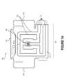
図1A及び1Bはそれぞれ、本技術の実施形態に係る、細長い支持体表面によって印加される特定の解剖学的領域における圧力を緩和するための圧力緩和装置100の上面図及び底面図である。圧力緩和装置100は、マットレス、担架、手術台及び検査台等の細長い支持体表面と組み合わせて使用され得る。いくつかの実施形態では、圧力緩和装置100は、取付装置を使用して支持体表面に固定され、他の実施形態では、圧力緩和装置100は、支持体表面と直接接触して(すなわち、取付装置を間に備えずに)配置される。1A and 1B are top and bottom views, respectively, of a
図1Aに示すように、圧力緩和装置100は、少なくとも1つの側部支持体104に沿って位置決めされた中央部分102(「接触部分」とも称される)を含み得る。ここで、一対の側部支持体104は、中央部分102の両側に配置されている。しかしながら、圧力緩和装置100のいくつかの実施形態は、側部支持体を何ら含んでいない。例えば、(1つ以上の)側部支持体104は、個人が(例えば、麻酔下で、医学的に誘発された昏睡状態において、等)医学的に動けなくされている際、並びに/又は、下方の支持体表面(例えば、ベッドの側部に沿ったレール、椅子の側部に沿った肘掛けによって)及び/若しくは他の構造(例えば、患者を押さえつける物理的拘束具、ギプス等)によって物理的に拘束されている際には、省かれてもよい。As shown in FIG. 1A, the
圧力緩和装置100は、圧力を個別に変化させることが可能な一連のチャンバ106(「セル」とも称される)を含む。いくつかの実施形態では、一連のチャンバ106は、人体の1つ以上の特定の解剖学的領域への圧力を緩和するように設計された幾何学的パターンで配置されている。上記のように、人体と支持体表面との間に配置された際に、圧力緩和装置100は、(1つ以上の)チャンバの膨張、(1つ以上の)チャンバの収縮又はそれらの任意の組み合わせを制御可能に行うことによって、(1つ以上の)特定の解剖学的領域への圧力を変化させ得る。The
いくつかの実施形態では、幾何学的パターンは、特定の解剖学的領域が幾何学的パターンの標的領域108の上方に位置合わせされている際の該特定の解剖学的領域への圧力を緩和するように設計されている。図1A及び1Bに示すように、標的領域108は、人の解剖学的構造を圧力緩和装置100に対して適切に位置決めするために、圧力緩和装置100の中心点又は中心部分に相当していてもよい。例えば、標的領域108は、幾何学的パターンの中心地点に対応してもよい。しかしながら、特に圧力緩和装置100が対称でない場合には、標的領域108は必ずしも圧力緩和装置100の中心点でなくてもよい。標的領域108は、個人(例えば、医師、看護師、介護者又は患者自身)が、標的領域108上に配置されることになる人体の対応する解剖学的領域に標的領域108を容易に位置決め可能となるように印がつけられていてもよい。In some embodiments, the geometric pattern is designed to relieve pressure on a particular anatomical region when the particular anatomical region is aligned over a
圧力緩和装置100は、支持体表面に面するように設計された第1の部分110(「第1の層」又は「底層」とも称される)と、支持体表面によって支持された人体に面するように設計された第2の部分112(「第2の層」又は「上層」とも称される)とを含み得る。いくつかの実施形態では、第1の部分110は、支持体表面に直接隣接しており、他の実施形態では、第1の部分110は、圧力緩和装置100を支持体表面に固定することを補助するように設計された取付装置に直接隣接している。圧力緩和装置100は、様々な材料で構成されていてもよく、圧力緩和装置100の各構成要素の構成に使用される(1つ以上の)材料は、該構成要素によって体感される身体接触があるならば、その性質に基づいて選択されてもよい。例えば、第2の部分112は、多くの場合に皮膚と直接接触するため、柔らかい布又は通気性の布(例えば、吸湿性材料若しくは速乾性材料で構成される布、又は、穿孔を有する布)で構成されていてもよい。いくつかの実施形態では、流体(例えば、汗)が一連のチャンバ106に入るのを妨げるために、(例えば、ポリウレタンで構成される)不浸透性のライニングが、第2の部分112の内側に固定される。別の例として、圧力緩和装置100がカバー(例えば、ベッドシーツ)の下に配備するように設計されている場合には、第2の部分112は、ポリウレタン、ポリプロピレン、シリコーン又はゴム等の液体不浸透性の可撓性材料で構成されていてもよい。また、第1の部分110も、液体不浸透性の可撓性材料で構成されていてもよい。The
一連のチャンバ106は、第1の部分110と第2の部分112との間の相互接続を介して(例えば、直接又は1つ以上の中間層を介してのいずれかにより)形成されてもよい。図1A及び1Bに示される実施形態では、圧力緩和装置100は、互いに向かい合う2つの「C字型」チャンバと絡み合った「M字型」チャンバを含んでいる。このような配置は、これらのチャンバ内の圧力が交番になっている際に、支持体表面によって仰臥位における人体の仙骨領域に印加される圧力を効果的に緩和することが示されている。圧力緩和装置が仙骨領域以外の解剖学的領域のために設計されている場合、又は、圧力緩和装置が仰臥位以外(例えば、座位)において人体を支持するために使用される場合、圧力緩和装置は別のチャンバ配置を有していてもよい。全般的に、チャンバ106の幾何学的パターンは、圧力が和らげられることとなる特定の解剖学的領域の内部解剖学的構造(例えば、筋肉、骨及び血管系)に基づいて設計される。The series of
圧力緩和装置100を使用する人及び/又はその介護者(例えば、看護師、医師等)は、患者の解剖学的領域を、幾何学的パターンの標的領域108上で長さ方向に能動的に位置合わせする役割を担うことが多い。しかしながら、(1つ以上の)側部支持体104は、人体の特定の解剖学的領域を、幾何学的パターンの標的領域108上で横方向に能動的に位置合わせ又は誘導してもよい。いくつかの実施形態では、(1つ以上の)側部支持体104は膨張式であり、他の実施形態では、(1つ以上の)側部支持体104は、圧力緩和装置100の一方又は両方の横側部から突出した永久構造物である。例えば、各側部支持体の少なくとも一部には、綿、ラテックス、ポリウレタンフォーム又はそれらの任意の組み合わせが詰められていてもよい。The person using the
図6A及び6Bに関して以下でさらに説明するように、コントローラデバイスは、各チャンバ(及び含まれる場合は側部支持体104)内の圧力を、1つ以上の対応する弁114を介して個別の気流を供給することによって、別々に制御し得る。いくつかの実施形態では、弁114は、圧力緩和装置100に恒久的に固定され、(例えば、輸送、保管等をより容易にするために)容易に取り外し可能な配管とインタフェースするように設計される。ここで、圧力緩和装置100は、5つの弁114を含む。3つの弁が一連のチャンバ106に流体的に結合され、2つの弁が側部支持体104に流体的に結合されている。他の実施形態では、圧力緩和装置100は、5つを超える弁114及び/又は5つ未満の弁114を含んでいる。6A and 6B, the controller device may separately control the pressure in each chamber (and
いくつかの実施形態では、圧力緩和装置100は、支持体表面及び/又は取付装置への圧力緩和装置100の固定を強化する1つ以上の構造的特徴116a~cを含む。図1Bに示すように、例えば、圧力緩和装置100は、3つの設計特徴116a~cを含むことができ、それらの設計特徴116a~cのそれぞれは、支持体表面又は取付装置に沿ってアクセス可能な対応する構造的特徴と位置合わせさせられ得る。例えば、各設計特徴116a~cは、上方に突出する構造的特徴を少なくとも部分的に包囲するように設計されてもよい。設計特徴116a~cはまた、圧力緩和装置100と支持体表面又は取付装置との適切な位置合わせを容易にしてもよい。In some embodiments, the
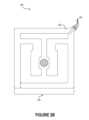
図2A及び2Bはそれぞれ、本技術の実施形態に従って構成される圧力緩和装置200の上面図及び底面図である。圧力緩和装置200は、一般的に、椅子(例えば、事務用椅子、検査用椅子、リクライナ及び車椅子)や車両及び飛行機に含まれる座席等、座位又は部分的に立位にある個人を支持する細長くない支持体表面と組み合わせて使用される。そのため、圧力緩和装置200はしばしば、支持体自体に統合された側部支持体(リクライナ又は車椅子の側部アームなど)を備えた支持体表面の上に位置決めされることになる。いくつかの実施形態では、圧力緩和装置200は、取付装置を使用して支持体表面に固定され、他の実施形態では、圧力緩和装置200が下方の支持体表面に直接接触するように、取付装置が省かれる。2A and 2B are top and bottom views, respectively, of a
圧力緩和装置200は、図1A及び1Bに関して上記にて説明された圧力緩和装置100の特徴と概ね同様の様々な特徴を含み得る。例えば、圧力緩和装置200は、支持体表面に面するように設計された第1の部分202(「第1の層」又は「底層」とも称される)と、支持体表面によって支持された人体に面するように設計された第2の部分204(「第2の層」又は「上層」とも称される)と、第1の部分202と第2の部分204との間の相互接続を介して形成された複数のチャンバ206とを含んでいてもよい。本実施形態では、圧力緩和装置200は、後方の「J字型」チャンバ206及び後方の「C字型」チャンバ206と絡み合った「M字型」チャンバ206を含んでいる。このようなチャンバ206の配置における交番の膨張/収縮は、人体が座位にある際に支持体表面によって仙骨領域に印加される圧力を効果的に緩和することが示されている。The
これらのチャンバ206の個々の膨張/収縮は、所定のパターンで、所定の圧力レベルとなるまで実行され得る。圧力緩和装置200によって支持される人体は座位にあることから、人体が仰臥位又は腹臥位にある場合よりも圧力緩和装置200により大きな圧力がかかるため、いくつかの実施形態では、例えば、個々のチャンバ206は、図1A及び1Bに関して説明された圧力緩和装置100のチャンバ206よりも高い圧力レベルにまで膨張させられ得る。さらに、図1A及び1Bの圧力緩和装置100とは異なり、図2A及び2Bの圧力緩和装置200は、側部支持体を含んでいない。上記のように、構造上に個人が座っている又はリクライニングしている該構造物が、既にその者を横方向中央に配置する構成要素(例えば、ベッドの側部に沿ったレール、椅子の側部に沿った肘掛け)を提供している場合、側部支持体は省かれてもよい。このことは、支持体表面が細長くない場合に多く該当する。The individual inflation/deflation of these
図6A及び6Bに関して以下でさらに説明するように、コントローラは、各チャンバ206内の圧力を、1つ以上の対応する弁208を介して個別の気流を供給することによって制御し得る。ここで、圧力緩和装置200は、3つの弁208を含んでおり、3つの弁208のそれぞれが、単一のチャンバ206に対応する。他の実施形態では、圧力緩和装置200は、1つの弁、2つの弁又は3つを超える弁208を含んでいてもよく、各弁208は、個別に制御される特定のチャンバの膨張及び/又は収縮のために、該特定のチャンバ206に関連付けられ得る。これらの実施形態及び他の実施形態では、単一の弁208は、2つ以上のチャンバ206に流体的に結合され得る。これらの実施形態及び他の実施形態では、単一のチャンバ206は、2つ以上の弁208(例えば、ある膨張用の弁及び別の収縮用の弁)と流体連通し得る。6A and 6B, the controller may control the pressure in each
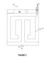
図3は、本技術の実施形態に係る、車椅子によって印加される特定の解剖学的領域における圧力を緩和するための圧力緩和装置300の上面図である。圧力緩和装置300は、上記の図2A及び2Bの圧力緩和装置200並びに図1A及び1Bの圧力緩和装置100の特徴と概ね同様の様々な特徴を含み得る。例えば、圧力緩和装置300は、車椅子の座席(すなわち、支持体表面)に面するように設計された第1の部分302(「第1の層」又は「底層」とも称される)と、車椅子の座席によって支持された人体に面するように設計された第2の部分304(「第2の層」又は「上層」とも称される)と、第1の部分302と第2の部分304との間の相互接続を介して形成された複数のチャンバ306と、該複数のチャンバ306から出る流体及び/又は該複数のチャンバ306に入る流体の流れを制御する複数の弁308とを含んでいてもよい。いくつかの実施形態では、第1の部分302は車椅子の座席に直接隣接し、他の実施形態では、第1の部分302は取付装置に直接隣接している。図3に示すように、圧力緩和装置300は、「U字型」チャンバ306及び「C字型」チャンバ306と絡み合った「M字型」チャンバ306を含んでいてもよく、これらのチャンバ306は、車椅子の座席上での座位における人体の仙骨領域に印加される圧力を緩和するために、所定のパターンに従って膨張及び収縮される。3 is a top view of a
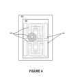
図4は、本技術の実施形態に係る、運動障害のある患者の虚血を回避するための様々な圧力分布を示す、圧力緩和装置400の部分概略上面図である。上記にて説明したように、人体が接触表面402によって長期間にわたって支持されている際には、仙骨、尾骨、踵又は股関節を覆う皮膚のような、骨の隆起を覆う組織内に圧迫創傷が形成される可能性がある。これらの骨の隆起は、しばしば接触表面402によって最も圧力が印加される1つ以上の位置に相当し、したがって、人体の表面に沿った「(1つ以上の)主要圧力点」と称されることがある。圧迫創傷の形成を予防するため、健康な者は、定期的に軽い体位調整(「微調整」としても知られる)を行い、それによって主要圧力点の位置をシフトさせている。しかしながら、運動障害のある人は、自分でこれらの微調整を行えないことが多い。運動障害は、身体的傷害(例えば、外傷性創傷又は進行性創傷)、運動制限(例えば、車内、航空機内又は拘束中)、医療処置(例えば、麻酔を必要とするもの)及び/又は個人の自然な動きを制限する他の条件に起因することがある。これらの運動障害のある者のために、圧力緩和装置400は、主要圧力点の位置をそれらの者に代わってシフトするために使用され得る。すなわち、圧力緩和装置400は、持続的で局所的な血管圧迫を回避し、組織灌流を増強するために、移動する圧力勾配を作り出し得る。4 is a partial schematic top view of a
図4に示すように、圧力緩和装置400は、圧力を個別に変化させることが可能な一連のチャンバ404(「セル」とも称される)を含み得る。チャンバ404は、圧力緩和装置400の第1の層(又は、底層)と第2の層(又は、上層)との間の相互接続によって形成されてもよい。上層は、人体と直接接触するように構成された第1の材料(例えば、通気性の非刺激性材料)で構成されてもよく、底層は、接触表面402又は取付装置と直接接触するように構成された第2の材料(例えば、非通気性のグリップ材料)で構成されてもよい。これらの実施形態及び他の実施形態では、上層及び/又は底層は、コーティングされた布又は相互接続された材料の積層体等の複数の材料で構成され得る。As shown in FIG. 4, the
ポンプは、図13に関して以下に説明する圧力装置1314のようなものであって、各チャンバ404に(例えば、対応する入口弁を介して)流体的に結合され得る一方で、コントローラは、図13に関して以下に説明するコントローラ1312のようなものであって、ポンプによって生成された、各チャンバ404内への流体(例えば、空気)の流れを、所定のパターンに従って個別に制御し得る。以下でさらに説明するように、ポンプ及びコントローラは、一連のチャンバ404をいくつかの異なる方法で操作し得る。いくつかの実施形態では、チャンバ404は、自然に収縮した状態を有し、コントローラは、ポンプによって少なくとも1つのチャンバ404を膨張させ、それによって主要圧力点をユーザの解剖学的構造に沿ってシフトさせる。例えば、ポンプは、解剖学的領域の真下に位置するチャンバ404の少なくとも1つを膨張させ、それによって該解剖学的領域に瞬間的に接触圧力を印加し、収縮した(1つ以上の)チャンバ404に隣接する周囲の解剖学的領域における接触圧力を和らげてもよい。これらの実施形態及び他の実装形態では、コントローラは、ポンプによって解剖学的領域に隣接する2つ以上のチャンバ404を膨張させ、それによって該解剖学的領域の下方に開放空間又は空所を作成して、主要圧力点を少なくとも瞬間的に該解剖学的領域から離れるようにシフトする。他の実施形態では、チャンバ404は自然に膨張した状態を有し、コントローラは、ポンプによって少なくとも1つのチャンバ404を収縮させ、それによって主要圧力点をユーザの解剖学的構造に沿ってシフトさせる。例えば、ポンプは、解剖学的領域の真下に位置するチャンバ404の少なくとも1つを収縮させ、それによって該解剖学的領域の下方に空所を形成して、解剖学的領域上の接触圧力を瞬間的に和らげるように構成されてもよい。自然に収縮した状態又は自然に膨張した状態のいずれに構成されていても、個々のチャンバ404の膨張レベルの連続的又は断続的な変更は、主要圧力点の位置を人体の種々異なる部分にわたって移動させる。図4に示すように、例えば、チャンバ404を膨張及び/又は収縮させることにより、圧力緩和装置400にわたって所定のパターンで移動する一時的な接触領域406が作成され、それによって、人体上の(1つ以上の)主要圧力点の位置が有限の時間間隔にて変化する。このようにして、圧力緩和装置400は、動ける個人によってなされる微調整をシミュレートすることができ、それによって接触表面402によって生じる停滞圧力の印加を和らげることができる。A pump, such as a
上記のように、一連のチャンバ404は、解剖学的に特定のパターンで配置されてもよく、その結果、1つ以上の個々のチャンバ内の圧力が変更される際に、(例えば、主要圧力点を他の場所にシフトすることによって)人体の特定の解剖学的領域の接触圧力が和らげられる。図4に示すように、例えば、主要圧力点は、8つの一時的な接触領域406に対応する8つの異なる位置の間で移動させられ得る。いくつかの実施形態では、主要圧力点は、予測可能な様式で(例えば、時計回り又は反時計回りのパターンで)これらの位置の間をシフトし、他の実施形態では、主要圧力点は、予測不可能な様式で(例えば、ランダムパターン、準ランダムパターン及び/又は検出された圧力レベルに従って)これらの位置の間をシフトする。当業者は、これらの一時的な接触領域406の量及び位置が、一連のチャンバ404の配置、圧力緩和装置400によって支持される解剖学的領域、圧力緩和装置400によって支持される人体の特性、及び/又は、ユーザの状態(例えば、ユーザが完全に動けなくされている、部分的に動けなくされている等)に基づいて変化し得ることを認識するであろう。As described above, the series of
いくつかの実施形態では、ユーザ(「患者」とも称される)の状態が側部支持体により提供される位置決めによる利益を得られない可能性があるため、圧力緩和装置400は、側部支持体を含まない。例えば、側部支持体は、患者が(例えば、麻酔下で、医学的に誘発された昏睡状態において、等)医学的に動けなくされている際、並びに/又は、下方の支持体表面(例えば、ベッドの側部に沿ったレール、椅子の側部上の肘掛け)及び/若しくは他の構造(例えば、患者を押さえつける物理的拘束具、ギプス等)によって物理的に拘束されている際には、省かれ得る。In some embodiments, the
図5Aは、本技術の実施形態に係る、チャンバ収縮によって特定の解剖学的領域への圧力を和らげるための圧力緩和装置502aの部分概略側面図である。圧力緩和装置502aは、接触表面500(例えば、ベッド、テーブル又は椅子)と人体504との間に位置決めされ得るものであり、人体504の特定の解剖学的領域における圧力を和らげるために、特定の解剖学的領域に近接する複数のチャンバ(まとめて「チャンバ508」と呼ばれる)のうち少なくとも1つのチャンバ508aが少なくとも部分的に収縮し、それによって該特定の解剖学的領域の下方に開放領域又は空所506aを作成する。そのような実施形態では、残りのチャンバ508が膨張したままであってもよい。このようにして、圧力緩和装置502aは、接触表面500によって人体504に印加された接触圧力を和らげるために、チャンバ508(又は複数のチャンバの配置)を順次収縮させてもよい。5A is a partial schematic side view of a
図5Bは、本技術の実施形態に係る、チャンバ膨張によって特定の解剖学的構造への圧力を和らげるための圧力緩和装置502bの部分的に概略的な側面図である。例えば、人体504の特定の解剖学的領域における圧力を和らげるために、圧力緩和装置502bは、特定の解剖学的領域に直接隣接して配置された2つのチャンバ508b及び508cを膨張させることができ、それによって該特定の解剖学的領域の下方に空所506bを作成し得る。そのような実施形態では、残りのチャンバが少なくとも部分的に収縮したままであってもよい。このようにして、圧力緩和装置502bは、接触表面500によって人体504に印加された接触圧力を和らげるために、チャンバ(又は複数のチャンバの配置)を順次膨張させてもよい。5B is a partially schematic side view of a
図5A及び5Bの圧力緩和装置502a及び502bは、接触表面500と直接接触していることが示されている。しかしながら、いくつかの実施形態では、取付装置は、圧力緩和装置502a及び502bと接触表面500との間に位置決めされる。The
いくつかの実施形態では、図5A及び5Bの圧力緩和装置502a及び502bは、同じ構成のチャンバ508を有し得ると共に、オペレータ(例えば、医療専門家又はユーザ)の選択に基づいて、標準で膨張した状態(図5Aに関して説明される)及び標準で収縮した状態(図5Bに関して説明される)の両方で動作することができる。例えば、オペレータは、コントローラを使用して、圧力緩和デバイスが図5Aに関して説明したように動作するように標準で収縮したモードを選択した後、圧力緩和デバイスが図5Bに関して説明したように動作するように、動作モードを標準で膨張したモードに変更することができる。したがって、本明細書に開示される圧力緩和装置は、制御可能に膨張するチャンバ、制御可能に収縮するチャンバ又はそれらの組み合わせによって、主要圧力点の位置をシフトさせることができる。In some embodiments, the
コントローラデバイスの選択された実施形態
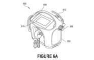
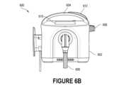
図6A~6Cは、それぞれ、本技術の実施形態に係る、圧力緩和装置のチャンバの膨張及び/又は収縮を開始するためのコントローラデバイス600(「コントローラ600」とも称される)の等角図、正面図及び背面図である。例えば、コントローラ600は、図1A~3に関して上記した圧力緩和装置100,200,300に結合されることができ、それによってチャンバ106,206,306内の圧力を制御し得る。コントローラ600は、1つ以上のポンプを制御可能に駆動することによって、圧力緩和装置の各チャンバ内の圧力を管理することができる。いくつかの実施形態では、単一のポンプが全てのチャンバに流体的に接続され、その結果、該ポンプは、流体の流れを複数のチャンバへと導く、及び/又は、複数のチャンバから導く役割を担う。他の実施形態では、コントローラ600は、2つ以上のポンプに結合され、それらのそれぞれは、単一のチャンバに流体的に結合されることができ、それによって該チャンバの膨張/収縮を駆動し得る。他の実施形態では、コントローラ600は、2つ以上のチャンバに流体的に結合された少なくとも1つのポンプ、及び/又は、単一のチャンバに流体的に結合された少なくとも1つのポンプに結合される。(1つ以上の)ポンプは、システムが簡単に持ち運びできるように、コントローラ自体と同じ筐体内に配置され得る。あるいは、1つ又は複数のポンプは、コントローラとは別の筐体内に存在し得る。Selected Embodiments of the Controller Device FIGS. 6A-6C are isometric, front, and rear views, respectively, of a controller device 600 (also referred to as “
図6A~6Cに示すように、コントローラ600は、内部コンポーネント(例えば、図7に関して以下に説明されるもの)が中に存在する筐体602と、筐体602に接続されたハンドル604とを含み得る。いくつかの実施形態では、ハンドル604は、筐体602に所定の向きに固着して固定され、他の実施形態では、ハンドル604は、筐体602に枢動可能に固定される。例えば、ハンドル604は、複数の位置の間において、筐体に接続されたヒンジの周りを回転するように構成されていてもよい。該ヒンジは、対向する側面に沿って筐体602に接続された一対のヒンジのうちの1つであってもよい。いくつかの実施形態では、コントローラデバイス600は、筐体606に取り付けられた又は筐体606と統合されたコード保持機構607を含むことができる。本システムに関連するコード(例えば、電気コード)、チューブ及び/又は他の細長い構造物は、コード保持機構607によって巻き付けられ得る、あるいはコード保持機構607によって支持され得る。したがって、コード保持機構607は、電力コードの歪み軽減(strain relief)及び保持を提供することができ、所定の実施形態では、電力コードプラグを保持する可撓性フランジを提供することもできる。6A-6C, the
図6A~6Cにさらに示すように、コントローラ600は、筐体602を構造体(例えば、移動式カート、ベッドフレーム、レール、テーブル)に固着して、しかしながら解放可能に、取り付けることを可能にする接続機構612を含んでいてもよい。図示の実施形態では、接続機構612は据付フックであり、そのような据付フックは、片手操作を可能にすると共に、様々な厚さの据付表面への取り付けを可能にするように調整可能である。いくつかの実施形態では、コントローラデバイス600は、コントローラデバイス600の点滴用ポール(IV (intravenous) pole)への取り付けを容易にする統合された点滴用ポールクランプ613を含むことができる。点滴用ポールクランプは、迅速に作動するようにされていてもよく、単一の作動機構(例えば、ノブ又はボタン)を使用してセルフセンタリング可能である。6A-6C, the
いくつかの実施形態では、筐体602は、コントローラ600に命令を提供するための1つ以上の機械的入力コンポーネント606を含む。入力コンポーネント606は、1つ以上のノブ(例えば、図6A~6Cに示されるようなもの)、ダイヤル、ボタン、レバー及び/又は他の作動機構を含んでいてもよい。オペレータは、圧力緩和装置に提供される気流を変更するように、圧力緩和装置から空気を排出するように、又は、コントローラ600を圧力緩和装置から(例えば、コントローラ600を、コントローラ600と圧力緩和装置とを接続する配管から切断することによって)切断するように、1つ以上の入力コンポーネント606を対話操作し得る。In some embodiments, the
以下でさらに説明するように、コントローラ600は、圧力緩和装置の個々のチャンバを既定のパターンで膨張及び/又は収縮させるように構成することができる。いくつかの実施形態では、少なくとも1つの圧力装置(例えば、空気ポンプ)は、コントローラ600の筐体602内に存在し、他の実施形態では、コントローラ600が少なくとも1つの圧力装置に流体的に接続される。例えば、筐体602は、流体が通過して(1つ以上の)圧力装置から受けられる第1の流体インタフェースと、流体が通過して圧力緩和装置へと導かれる第2の流体インタフェースとを含んでいてもよい。多チャンネル配管は、これらの流体インタフェースの一方又は両方に接続されていてもよい。例えば、多チャンネル配管は、コントローラ600の第1の流体インタフェースと複数の圧力装置との間に接続されていてもよい。別の例として、多チャンネル配管は、コントローラ600の第2の流体インタフェースと圧力緩和装置の複数の弁との間に接続されていてもよい。ここで、コントローラ600は、多チャンネル配管とインタフェースするように設計された流体インタフェース608を含む。いくつかの実施形態では、多チャンネル配管は、一方向の流体の流れを可能にし、他の実施形態では、多チャンネル配管は、双方向の流体の流れを可能にする。したがって、圧力緩和装置から(例えば、排出プロセスの一部として)戻る流体は、第2の流体インタフェースを通過してコントローラ600へと戻るよう移動してもよい。圧力緩和装置から戻る流体の排出を制御することによって、コントローラ600は、使用中に発生する騒音を能動的に管理することができる。As described further below, the
流体インタフェース608との接続を監視することによって、コントローラ600は、どのタイプの圧力緩和装置が接続されているかを検出可能であってもよい。各タイプの圧力緩和装置はそれぞれ、異なるタイプのコネクタを含んでいてもよい。例えば、細長い支持体表面用に設計された圧力緩和装置(例えば、図1A~Bの圧力緩和装置100)は、該装置のコネクタ内に第1の配置の磁石を含んでいてもよく、一方、細長くない支持体表面用に設計された圧力緩和装置は、表面(例えば、図2A~Bの圧力緩和装置)は、該装置のコネクタ内に第2の配置の磁石を含んでいてもよい。コントローラ600は、磁石が指定の近接範囲内に配置されているかどうかを検出するために、流体インタフェース608の近くに配置された1つ以上のセンサを含んでいてもよい。コントローラ600は、どのような磁石がセンサによって検出されたかに基づいて、どのタイプの圧力緩和装置が接続されているかを自動的に決定してもよい。例えば、圧力緩和装置は、様々な異なる患者の位置(例えば、仰臥位、腹臥位、座位)、その上に患者が居るように設計された支持体表面(例えば、車椅子、ベッド、リクライナ、手術台)及び/又は患者の特性(例えば、指示(indication)、サイズ)に適した種々異なる形状、レイアウト及び/又は寸法を有していてもよく、コントローラは、該コントローラに接続された圧力緩和装置のタイプを自動的に検出するように構成され得る。いくつかの実施形態では、自動検出は、他の適切な識別メカニズムを使用して実行することができ、そのようなメカニズムとして、圧力緩和デバイス上のRFIDタグ又はバーコードを読み取るコントローラデバイス600等が挙げられる。以下でさらに説明するように、コントローラ600は、どのタイプの圧力緩和装置が接続されているかに基づいて、膨張するチャンバのパターンを動的に変更するように構成され得る。By monitoring the connection with the
コントローラ600はまた、圧力緩和装置、膨張/収縮のパターン、患者等に関連する情報を表示するためのディスプレイ610を含んでいてもよい。例えば、ディスプレイ610は、どのタイプの圧力緩和装置(例えば、図1A~3の圧力緩和装置100,200,300)がコントローラ600に接続されているかについて指定するインタフェースを提示してもよい。他の表示技術もまた、コントローラ600のオペレータに情報を伝達するために使用され得る。いくつかの実施形態では、コントローラ600は、オペレータ又はユーザに視覚的な警告を提供するための種々異なる状態を表す一連のライト(例えば、発光ダイオード)を含む。例えば、状態ライトは、コントローラ600が現在治療を提供している場合は緑色の視覚的表示、コントローラ600が一時停止されている場合(すなわち、一時停止モードにある場合)は黄色の視覚的表示、コントローラ600に問題が生じている(例えば、患者の非遵守、デバイス上に患者が検出されない)又はメンテナンスが必要な場合(つまり、警告モードにある場合)は赤色、の視覚的表示、等を提供してもよい。これらの視覚的表示は、指定の期間が終了した際、又は、ステータスが変更された(例えば、一時停止モードがアクティブではなくなった)際に、暗くなってもよい。The
いくつかの実施形態では、コントローラデバイス600はまた、臨床医が圧力緩和デバイスの全部又は一部(例えば、側部チャンバ)を急速に収縮させることを可能にする迅速又は急速な収縮機能を含むことができる。この機能は、コントローラデバイス600によって提供されて、ディスプレイ610(例えば、タッチスクリーンボタンを備えたユーザインタフェースとして構成された場合)及び/又はデバイス上の触覚アクチュエータ(例えば、ボタン)を介してアクティブ化される、ソフトウェアソリューションである。この急速な収縮、特にサイドピローの収縮は、患者への迅速なアクセス(例えば、CPRを提供すること)が必要な場合に、臨床医にとって有益であると期待される。In some embodiments, the
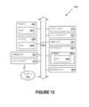
図7は、本技術の実施形態に係る、コントローラ700のコンポーネントを示すブロック図である。コントローラ700は、1つ以上のプロセッサ702、通信モジュール704、分析モジュール706、マニホールド708、メモリ710、及び/又は、電力インタフェース714に電気的に結合された電力コンポーネント712を含むことができる。これらのコンポーネントは、図6A~6Cに関して上記で説明されたコントローラデバイス筐体602などの筐体(「構造体」とも呼ばれる)内に存在していてもよい。いくつかの実施形態では、コントローラ700は、圧力緩和システムの他の筐体又はコンポーネントに組み込まれることができ、これには、圧力緩和装置にリモートで結合されることが含まれる。コントローラ700の実施形態は、図7に示されるコンポーネントの任意のサブセット、及び、図7に示されていない追加のコンポーネントを含むことができる。例えば、コントローラ700のいくつかの実施形態は、データが通って別のコンピューティングデバイスに送信され得る物理データインタフェースを含む。物理データインタフェースの例には、イーサネットポート、ユニバーサルシリアルバス(USB)ポート及び専用ポートが含まれる。7 is a block diagram illustrating components of a controller 700, according to an embodiment of the present technology. The controller 700 may include one or more processors 702, a communication module 704, an
コントローラ700は、圧力が個別に変化され得る一連のチャンバを含む圧力緩和装置に接続されてもよい。圧力緩和装置が人体と支持体表面との間に配置される際に、コントローラ700は、1つ以上のチャンバを制御可能に膨張させる、1つ以上のチャンバを収縮させる又はそれらの任意の組み合わせを行うことによって、人体の解剖学的領域への圧力を変化させることができる。そのような作用は、圧力緩和装置の一連のチャンバへの流体の流れを制御するマニホールド708によって達成することができる。マニホールド708は、図8及び9に関してさらに説明される。The controller 700 may be connected to a pressure relief device that includes a series of chambers in which pressure can be individually varied. When the pressure relief device is placed between the body and a support surface, the controller 700 can vary the pressure on an anatomical region of the body by controllably inflating one or more chambers, deflating one or more chambers, or any combination thereof. Such action can be accomplished by a manifold 708 that controls the flow of fluid to the series of chambers of the pressure relief device. The manifold 708 is further described with respect to FIGS. 8 and 9.
以下でさらに説明するように、マニホールド708に据え付けられたトランスデューサは、圧力緩和装置のチャンバ内で検出された圧力に基づいて電気信号を生成することができる。一般に、各チャンバは、異なる流体チャンネル及び異なるトランスデューサに関連付けられている。したがって、マニホールド708が4チャンバ圧力緩和装置への流体の流れを容易にするように設計されている場合、マニホールド708は、4つの流体チャンネル及び4つのトランスデューサを含んでいてもよい。いくつかの実施形態では、マニホールド708は、4つ未満の流体チャンネル及び/又はトランスデューサ、又は4つを超える流体チャンネル及び/又はトランスデューサを含んでいてもよい。トランスデューサによって生成された電気信号の値を表す圧力データは、メモリ710内に、少なくとも一時的に格納することができる。いくつかの実施形態では、(1つ以上の)プロセッサ702は、分析モジュール706による検査の前に、圧力データを処理する。例えば、プロセッサ702は、時間的整列、アーチファクト除去等のために設計されたアルゴリズムを適用してもよい。As described further below, the transducers mounted on the manifold 708 can generate electrical signals based on pressures detected within the chambers of the pressure relief device. Generally, each chamber is associated with a different fluid channel and a different transducer. Thus, if the manifold 708 is designed to facilitate fluid flow to a four-chamber pressure relief device, the manifold 708 may include four fluid channels and four transducers. In some embodiments, the manifold 708 may include fewer than four fluid channels and/or transducers, or more than four fluid channels and/or transducers. Pressure data representing values of the electrical signals generated by the transducers can be stored, at least temporarily, in the memory 710. In some embodiments, the processor(s) 702 process the pressure data prior to review by the
この圧力データをポンプからコントローラ700に流入する流体を表す流れデータと併せて調査することによって、分析モジュール706は、圧力緩和装置のチャンバがどのように膨張及び/又は収縮するかを制御することができる。例えば、分析モジュール706は、各チャンバへの流体の流れについての設定点を、別々に制御する役割を担ってもよい。By examining this pressure data in conjunction with flow data representing fluid flowing from the pump to the controller 700, the
さらに、この圧力データを調査することによって、分析モジュール706は、圧力緩和装置が配置されている人体の動きを感知可能であってもよい。これらの動きは、患者、別の個人(例えば、介護者又はコントローラ700の操作者)、又は下方の支持体表面によって引き起こされてもよい。分析モジュール706は、反復的な動き及び/又はランダムな動きを識別することによって患者の健康状態をよりよく理解するために、これらの動きを表すデータ(「動きデータ」又は「モーションデータ」とも称される)にアルゴリズムを適用してもよい。例えば、分析モジュール706は、患者の動きに基づいて呼吸数又は心拍数を確立可能であってもよい。一般に、動きデータは、圧力データから導出可能である。これにより、圧力緩和装置は、加速度計、傾斜センサ又はジャイロスコープ等の動きを測定するためのセンサを、実際には含まなくてもよい。Furthermore, by examining this pressure data, the
圧力データを調査した後、分析モジュール706は、様々な方法において応答してもよい。例えば、分析モジュール706は、他のコンピューティングデバイスに送信される通知(例えば、警告)を、通信モジュール704によって生成してもよい。この他のコンピューティングデバイスは、医療専門家(例えば、医師又は看護師)、患者の家族又は他の何らかの主体(例えば、研究者又は保険者)に関連付けられてもよい。通信モジュール704は、近距離通信(NFC)、ワイヤレスUSB、Bluetooth、Wi-Fi、セルラーデータプロトコル(例えば、LTE、3G、4G若しくは5G)、又は、独自のポイントツーポイントプロトコル等の双方向通信プロトコルを介して、他のコンピューティングデバイスと通信してもよい。別の例として、分析モジュール706は、圧力データ(又は、そのようなデータの分析)を、患者の電子健康記録と統合させてもよい。一般に、電子健康記録は、ネットワークを介して通信モジュール704にアクセス可能な記憶媒体に保持される。After reviewing the pressure data, the
コントローラ700は、必要に応じて筐体内に存在する他のコンポーネントに提供可能な電力コンポーネント712を含んでいてもよい。電力コンポーネントの例には、充電式リチウムイオン(Li-Ion)電池、充電式ニッケル水素(NiMH)電池、充電式ニッケルカドミウム(NiCad)電池等が含まれる。いくつかの実施形態では、コントローラ700は、電力コンポーネントを含んでいないため、外部電源から電力を受ける必要となる。そのような実施形態では、コントローラ700の電力インタフェース714と外部電源との間に、(例えば、電気接点の物理的接続を介して)電力の伝達を容易にするように設計されたケーブルが接続されてもよい。外部電源は、例えば、交流(AC)電源ソケットであってもよく、別の電子デバイスであってもよい。The controller 700 may include a power component 712 that may provide power to other components present within the enclosure as needed. Examples of power components include rechargeable lithium ion (Li-Ion) batteries, rechargeable nickel metal hydride (NiMH) batteries, rechargeable nickel cadmium (NiCad) batteries, and the like. In some embodiments, the controller 700 does not include a power component and must receive power from an external power source. In such embodiments, a cable designed to facilitate the transfer of power (e.g., via a physical connection of electrical contacts) may be connected between the power interface 714 of the controller 700 and the external power source. The external power source may be, for example, an alternating current (AC) power socket or may be another electronic device.
図8は、本技術の実施形態に係る、圧力緩和装置のチャンバへの流体の流れ(例えば、空気の流れ)を制御するためのマニホールド800の等角図である。上記のように、コントローラは、圧力緩和装置のチャンバを膨張及び/又は収縮するように構成することができる。このことを達成するために、マニホールド800は、一連の弁802を介して流体をチャンバに導くことができる。いくつかの実施形態では、各弁802はそれぞれ、圧力緩和装置の別個のチャンバに対応する。いくつかの実施形態では、少なくとも1つの弁802が、圧力緩和装置の複数のチャンバに対応する。いくつかの実施形態では、少なくとも1つの弁802が、操作中に使用されない。例えば、圧力緩和装置が4つのチャンバを含む場合、圧力緩和装置とマニホールド800の4つの弁802との間に、多チャンネル配管が接続されてもよい。そのような実施形態では、他の弁は、動作中に塞がれたままであってもよい。8 is an isometric view of a manifold 800 for controlling the flow of fluid (e.g., air) to a chamber of a pressure relief device, according to an embodiment of the present technology. As described above, the controller can be configured to inflate and/or deflate the chamber of the pressure relief device. To accomplish this, the manifold 800 can direct fluid to the chambers through a series of
一般に、弁802は、電圧の印加に応答して、1つの状態(例えば、開状態)から別の状態(例えば、閉状態)に切り替わるように設計された圧電弁である。圧電弁は、リニア弁やソレノイドベースの弁など、他の弁に比べていくつかの利点を提供する。第1に、圧電弁は、状態を維持するために保持電流を必要としない。そのため、圧電弁は熱をほとんど発生させない。第2に、圧電弁は、状態を切り替える際にノイズをほとんど発生させない。このことは、医療現場で特に有用である。第3に、圧電弁は、マニホールド800がオーバーシュート又はアンダーシュートすることなく所与の流量に正確に近づくことを可能にする、制御された方法で開閉され得る。これに対し、上記した他の弁は、弁が完全に開いている開状態又は弁が完全に閉じている閉状態のいずれかの必要がある。第4に、圧電弁は、動作するのに電力をほとんど必要としないため、コントローラの電力コンポーネント(例えば、図7の電力コンポーネント712)は、任意の所与の時間において、マニホールド800に対して3~6ワットを供給するだけでよい。マニホールド800の実施形態は圧電弁の文脈で説明され得るが、圧電弁の代わりに又は圧電弁に加えて、線形弁又はソレノイドベースの弁等の他のタイプの弁も使用可能である。Generally, the
各圧電弁は、電気機械トランスデューサとして機能する少なくとも1つの圧電要素を含む。圧電素子に電圧を印加する際、圧電素子が変形し、それによって機械的な動き(弁の開閉など)が発生する。圧電素子の例には、ディスクトランスデューサ、屈曲アクチュエータ及び圧電スタック等が含まれる。Each piezoelectric valve includes at least one piezoelectric element that functions as an electromechanical transducer. When a voltage is applied to the piezoelectric element, the piezoelectric element deforms, thereby producing mechanical motion (such as opening or closing the valve). Examples of piezoelectric elements include disk transducers, bending actuators, and piezoelectric stacks.
いくつかの実施形態では、マニホールド800は、1つ以上のトランスデューサ806と、弁802及びトランスデューサ806との通信を管理するための1つ以上の集積回路(「チップ」とも称される)を含む回路基板804とを含む。これらのローカルチップは、マニホールド800自体の中に存在するため、弁802は精確な方法でデジタル制御することができる。ローカルチップはまた、コントローラの他のコンポーネントに接続されていてもよい。例えば、ローカルチップは、コントローラ内に収容されたプロセッサ(例えば、図7のプロセッサ702)に接続されていてもよい。一方で、トランスデューサ806は、圧力緩和装置の各チャンバの圧力に基づいて、電気信号を生成することができる。一般に、各チャンバはそれぞれ、異なる弁802及び異なるトランスデューサ806に関連付けられている。ここで、例えば、マニホールドは、圧力緩和装置とインタフェース可能な6つの弁802を含み、これらの弁のそれぞれは、対応するトランスデューサ802に関連付けられている。トランスデューサ806によって生成された電気信号の値を表す圧力データは、さらなる分析のためにコントローラの他のコンポーネントに提供され得る。In some embodiments, the manifold 800 includes one or
マニホールド800はまた、1つ以上の圧縮機を含んでいてもよい。いくつかの実施形態では、マニホールド800の各弁802は、同じ圧縮機に流体的に結合され、他の実施形態では、マニホールド800の各弁802はそれぞれ、異なる圧縮機に流体的に結合される。各圧縮機は、流体(例えば、空気)を圧力緩和装置に導く前に該流体の体積を減らすことによって、該流体の圧力を上昇させることができる。The manifold 800 may also include one or more compressors. In some embodiments, each
ポンプによって提供された流体は、まず、1つ以上の入口流体インタフェース808を通じて、マニホールド800によって受けられてもよい。上記のように、いくつかの実施形態では、圧縮機は、流体の体積を減らすことによって、該流体の圧力を上昇させてもよい。その後、マニホールド800は、弁802を通じて、流体を圧力緩和装置のチャンバ内に制御可能に案内することができる。各チャンバへの流体の流れは、回路基板804上に配置されたローカルチップによって制御することができる。例えば、(1つ以上の)ローカルチップは、弁802を開閉するように電圧を制御可能に印加することによって、リアルタイムで各チャンバへの流体の流れを動的に変化させることができる。Fluid provided by the pump may first be received by the manifold 800 through one or more inlet fluid interfaces 808. As noted above, in some embodiments, a compressor may increase the pressure of the fluid by reducing the volume of the fluid. The manifold 800 may then controllably direct the fluid through
いくつかの実施形態では、マニホールドは、1つ以上の出口流体インタフェース810を含む。出口流体インタフェース810は、圧力緩和装置の急速な収縮を可能にするために、高圧高流量用に設計されてもよい。例えば、オペレータが圧力緩和装置(又は、その一部)を収縮させる要求を示す入力を提供したと決定した際に、マニホールド800は、流体が圧力緩和装置から弁802を通って戻り、続いて出口流体インタフェース810を通って出るように移動することを可能にしてもよい。したがって、出口流体インタフェース810は、「排気」又は「出口(outlet)」とも称され得る。入力を提供するために、オペレータは、機械的入力コンポーネント(例えば、図6Aの機械的入力コンポーネント606)又はデジタル入力コンポーネント(例えば、図6Aのディスプレイ610上に見られる)を対話操作してもよい。In some embodiments, the manifold includes one or more outlet fluid interfaces 810. The outlet fluid interfaces 810 may be designed for high pressure and high flow rates to allow for rapid deflation of the pressure relief device. For example, upon determining that an operator has provided an input indicating a desire to deflate the pressure relief device (or a portion thereof), the manifold 800 may allow fluid to travel from the pressure relief device back through the
図9は、本技術の実施形態に係る、マニホールドの圧電弁902が複数のチャンネルに沿った流体の流れを別々に制御することができる方法を示す一般化された電気回路図である。図9では、マニホールドは、7つの圧電弁902を含む。他の実施形態では、マニホールドは、7つ未満の弁又は7つを超える弁を含んでいてもよい。流体は、マニホールドによって、圧電弁902を通って圧力緩和装置のチャンバへと導かれることができる。図9では、マニホールド900は、5つのチャンバを含む圧力緩和装置に流体的に接続されている。しかしながら、他の実施形態では、マニホールド900は、5つ未満のチャンバ又は5つを超えるチャンバを含む圧力緩和装置に流体的に接続されていてもよい。9 is a generalized electrical diagram illustrating how
マニホールドに含まれる圧電弁902の全ては、必ずしも互いに同一である必要はない。圧電弁は、高圧低流量、高圧高流量、低圧低流量又は低圧高流量向けに設計されていてもよい。いくつかの実施形態では、マニホールドに含まれる全ての圧電弁は同じタイプであるが、他の実施形態では、マニホールドは複数のタイプの圧電弁を含む。例えば、圧力緩和装置の側部支持体に対応する圧電弁は、(例えば、流体の迅速な排出を可能にするために)高圧高流量向けに設計されてもよいが、圧力緩和装置のチャンバに対応する圧電弁は、高圧低流量向けに設計されていてもよい。さらに、いくつか圧電弁が、双方向の流体の流れをサポートしていてもよく、他の圧電弁が一方向の流体の流れをサポートしていてもよい。一般に、マニホールド900が複数の一方向圧電弁を含む場合、圧力緩和装置の各チャンバは、流体がいずれか方向にも流れることを可能にするために、一対の一方向圧電弁に関連付けられる。ここでは、例えば、チャンバ1~3は単一の双方向圧電弁に関連付けられ、チャンバ4は2つの双方向圧電弁に関連付けられ、チャンバ5は2つの一方向圧電弁に関連付けられる。さらに、コントローラのマニホールドは、指定の圧力値を達成するために、圧力緩和装置の各チャンバを膨張及び/又は収縮するように構成されることができる。All of the
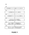
図10は、本技術の実施形態に係る人体と支持体表面との間に配置された圧力緩和装置のチャンバ内の圧力を変化させるためのプロセス1100のフロー図である。チャンバ内の圧力を変化させることにより、コントローラは、支持体表面によって印加される主要圧力点を人体全体にわたって動かすことができる。例えば、支持体表面によって人体に印加される主要圧力点は、膨張可能なチャンバの種々異なる所定のサブセット内の圧力を逐次的に変化させることによって、複数の所定位置間で動かされてもよい。FIG. 10 is a flow diagram of a
まず、コントローラは、圧力緩和装置がコントローラに接続されていることを決定することができる(ステップ1101)。流体インタフェース(例えば、図6Bの流体インタフェース608)と圧力緩和装置との接続を監視することによって、コントローラは、どのタイプの圧力緩和装置が接続されているかを検出することができる。いくつかの実施形態では、各タイプの圧力緩和装置はそれぞれ、異なるタイプのコネクタを含んでいてもよい。例えば、細長い支持体表面用に設計された圧力緩和装置(例えば、図1A~Bの圧力緩和装置100)は、該装置のコネクタ内に第1の配置の磁石を含んでいてもよく、一方、細長くない支持体表面用に設計された圧力緩和装置は、表面(例えば、図2A~Bの圧力緩和装置)は、該装置のコネクタ内に第2の配置の磁石を含んでいてもよい。コントローラは、指定の近接範囲内でどの磁石が検出されたかに基づいて、どのタイプの圧力緩和装置が接続されているかを決定してもよい。別の例として、細長い支持体表面用に設計された圧力緩和装置は、第1の電子署名を発信可能なビーコンを含んでいてもよく、一方、細長くない支持体表面用に設計された圧力緩和装置は、第2の電子署名を発信可能なビーコンを含んでいてもよい。ビーコンの例には、Bluetoothビーコン、USBビーコン及び赤外線ビーコンが含まれる。ビーコンは、有線通信チャンネル又は無線通信チャンネルを介して、コントローラと通信するように構成されていてもよい。First, the controller may determine that a pressure relief device is connected to the controller (step 1101). By monitoring the connection of the fluid interface (e.g.,
次に、コントローラは、圧力緩和装置に対応するパターンを識別することができる(ステップ1102)。例えば、コントローラは、適切なパターンを識別するために、種々異なる圧力緩和装置に対応するパターンのライブラリを調査してもよい。パターンのライブラリは、ローカルメモリ(例えば、図7のメモリ710)内に格納されていてもよく、ネットワークを介してコントローラにアクセス可能なリモートメモリ内に格納されていてもよい。別の例として、コントローラは、圧力緩和装置に基づいて、既存のパターンを修正してもよい。例えば、コントローラは、圧力緩和装置が含む命令よりもパターンが多くのチャンバの命令を含むとの決定に応答して、既存のパターンを変更してもよい。次に、コントローラは、圧力緩和装置のチャンバをパターンに従って膨張させることができる(ステップ1103)。より具体的には、コントローラは、1つ以上のチャンバを制御可能に膨張させる、1つ以上のチャンバを収縮させる又はそれらの任意の組み合わせによって、人体の1つ以上の解剖学的領域に対する圧力を変化させることができる。The controller may then identify a pattern corresponding to the pressure relief device (step 1102). For example, the controller may review a library of patterns corresponding to different pressure relief devices to identify an appropriate pattern. The library of patterns may be stored in a local memory (e.g., memory 710 of FIG. 7) or in a remote memory accessible to the controller over a network. As another example, the controller may modify an existing pattern based on the pressure relief device. For example, the controller may change an existing pattern in response to determining that the pattern includes instructions for more chambers than the pressure relief device includes instructions. The controller may then inflate the chambers of the pressure relief device according to the pattern (step 1103). More specifically, the controller may change pressure on one or more anatomical regions of the body by controllably inflating one or more chambers, deflating one or more chambers, or any combination thereof.
コントローラは、収縮手順を開始する要求を示す入力を受信してもよい(ステップ1104)。いくつかの実施形態では、入力は、(例えば、機械的入力コンポーネント又はデジタル入力コンポーネントの対話操作の結果として)オペレータによって手動で提供される命令に関連付けられる。例えば、操作者は、患者が圧力緩和装置へと/から移動する前に、収縮手順が開始されることを要求してもよい。別の例として、操作者は、患者の関与する医療処置(例えば、心肺蘇生法又は除細動)が実行される前に、収縮処置が開始されることを要求してもよい。他の実施形態では、入力は、コントローラによって自動的に生成される命令に関連付けられている。コントローラは、指定された基準が満たされることに応答して、命令を自動的に生成してもよい。例えば、コントローラは、チャンバ又は圧力緩和装置の側部支持体内の圧力が上限閾値を超えた際に、命令を自動的に生成してもよい。The controller may receive an input indicating a request to initiate the deflation procedure (step 1104). In some embodiments, the input is associated with an instruction provided manually by an operator (e.g., as a result of interaction with a mechanical or digital input component). For example, the operator may request that the deflation procedure be initiated before a patient is moved to or from the pressure relief device. As another example, the operator may request that the deflation procedure be initiated before a medical procedure involving the patient (e.g., cardiopulmonary resuscitation or defibrillation) is performed. In other embodiments, the input is associated with an instruction automatically generated by the controller. The controller may automatically generate the instruction in response to a specified criterion being met. For example, the controller may automatically generate the instruction when the pressure in the chamber or the side support of the pressure relief device exceeds an upper threshold.
その後、コントローラは、チャンバ、側部支持体又はそれらの任意の組み合わせを収縮させることができる(ステップ1105)。より具体的には、コントローラは、マニホールド(例えば、図8のマニホールド800)に対して、圧力緩和装置の少なくとも一部への流体の供給を停止するように、及び/又は、流体が圧力緩和装置から逃げることを可能にする圧力緩和装置の部分に対応する(1つ以上の)弁を開くように命令してもよい。The controller may then deflate the chamber, the side supports, or any combination thereof (step 1105). More specifically, the controller may instruct a manifold (e.g.,
図11は、本技術の実施形態に係る、人体と直接接触するセンサを配置することなく、圧力緩和装置によって支持された人体の特性を確立するためのプロセス1200のフロー図である。図12のステップ1201~1203は、図10のステップ1101~1103と、少なくとも概ね同様であってもよい。FIG. 11 is a flow diagram of a
上記のように、圧力緩和装置の膨張/収縮を管理する役割を担うコントローラは、圧力緩和装置の各チャンバの圧力に基づいて電気信号を生成するように構成された(1つ以上の)トランスデューサを含んでいてもよい。したがって、コントローラは、(1つ以上の)トランスデューサによって生成された電気信号の値を表す圧力データを取得してもよい(ステップ1204)。次に、コントローラは、圧力データを調査して、人体の(1つ以上の)動きを識別することができる(ステップ1205)。いくつかの実施形態では、コントローラは、圧力データの一部又は全てを、処理又は分析のためにリモート位置(例えば、中央サーバ)へと送信することができる。圧力緩和装置のチャンバの圧力を常に監視することによって、コントローラは、人体に直接接触するセンサを使用することなく、人体の動き/位置に関する情報を解釈することができる。As described above, the controller responsible for managing the inflation/deflation of the pressure relief device may include a transducer(s) configured to generate an electrical signal based on the pressure in each chamber of the pressure relief device. The controller may then obtain pressure data representing the value of the electrical signal generated by the transducer(s) (step 1204). The controller may then examine the pressure data to identify the movement(s) of the human body (step 1205). In some embodiments, the controller may transmit some or all of the pressure data to a remote location (e.g., a central server) for processing or analysis. By constantly monitoring the pressure in the chambers of the pressure relief device, the controller may interpret information regarding the movement/position of the human body without the use of sensors in direct contact with the human body.
リモート圧力監視を介した患者の動きの監視は、患者の運動性状態及び/又は患者の全体的な健康状態の指標として使用可能であると共に、完全に動いていない期間を特定することができる。このことは、患者の動きが、患者の健康状態の低下又は潜在的な健康上の合併症をも示すことができることを示している。リモート圧力監視はまた、患者がベッド、椅子又は患者緩和装置が配置されている他の表面を離れる時を検出することもでき、いくつかの実施形態では、この動きに対して注意を引くために、ローカル又はリモートの位置へと(例えば、介護者へと)提供される警告又は警報によって、この動きに応答することができる。このことは、患者の介護者が、患者が歩行可能であるときに転倒を回避することを支援したり、支持体表面からの転倒をリアルタイムで識別したりすることを可能にする。リモート圧力監視データはまた、患者がデバイスを適切に使用しているかどうか、患者が圧力緩和表面に適切に配置されているかどうか、患者が処方されたプロトコルを遵守しているかどうかを決定するために使用することもできる。この情報に基づいて、病院、介護者及び/又は患者の介護に関与する他の人々によってアクセス可能なリモートシステムへと警告又は警報が送信される。データのリアルタイムでの監視及び分析は、患者がプロトコルを遵守していない場合、及び/又はデバイスを適切に使用していない(例えば、位置が正しくない)場合に、介護者や管理者などに警告するための正確な警報を提供することができ、これによって、圧力緩和システムの適切な使用が促進されて、圧力緩和システムの利点が強化される。Monitoring of patient movement via remote pressure monitoring can be used as an indicator of the patient's mobility status and/or overall health status, as well as identifying periods of complete immobility. This indicates that patient movement can also indicate a decline in the patient's health or potential health complications. Remote pressure monitoring can also detect when the patient leaves the bed, chair, or other surface on which the patient relief device is located, and in some embodiments can respond to this movement with an alert or warning provided to a local or remote location (e.g., to a caregiver) to draw attention to this movement. This allows the patient's caregiver to assist the patient in avoiding falls when ambulatory, or to identify falls from the support surface in real time. Remote pressure monitoring data can also be used to determine whether the patient is using the device properly, whether the patient is properly positioned on the pressure relief surface, and whether the patient is adhering to the prescribed protocol. Based on this information, an alert or warning is sent to a remote system accessible by the hospital, the caregiver, and/or others involved in the patient's care. Real-time monitoring and analysis of the data can provide accurate alerts to alert caregivers, administrators, etc. if the patient is not adhering to protocol and/or is not using the device properly (e.g., incorrect positioning), thereby promoting proper use of the pressure relief system and enhancing the benefits of the pressure relief system.
コントローラ(又は、他の電子デバイス。例えば、携帯電話、ラップトップコンピュータ又はコンピュータサーバ等)は、圧力データ、(1つ以上の)動き又はそれらの任意の組み合わせに基づいて、人体の特性を推定することができる(ステップ1206)。例えば、コントローラは、圧力データを、(例えば、1つ以上のポンプから)コントローラへと流入する流体を表す流量データと併せて調査することによって、人体の重量を推定することが可能であってもよい。別の例として、コントローラは、動きに基づいて、人体の呼吸数又は心拍数を推定することが可能であってもよい。したがって、コントローラは、運動性状態等の人体の健康状態についての所定の態様を、非侵襲的な方法で理解することが可能であってもよい。The controller (or other electronic device, such as a mobile phone, laptop computer, or computer server) may estimate characteristics of the human body based on the pressure data, the motion(s), or any combination thereof (step 1206). For example, the controller may be able to estimate the weight of the human body by examining the pressure data in conjunction with flow data representative of fluid flowing into the controller (e.g., from one or more pumps). As another example, the controller may be able to estimate the respiration rate or heart rate of the human body based on the motion. Thus, the controller may be able to understand certain aspects of the health of the human body, such as the mobility state, in a non-invasive manner.
物理的可能性に反しない限り、上記のステップは、様々な順序及び組み合わせで実行されてもよいことが想定される。例えば、コントローラは、図10のプロセス1100及び図11のプロセス1200を同時に実行するように構成されていてもよい。いくつかの実施形態はまた、他のステップをも含んでいてもよい。例えば、コントローラは、所定の状況(例えば、人体の指定の解剖学的領域における不快感を示す動きを発見した際、圧力緩和装置を離れようとする試みを示す動きを発見した際、又は、指定された期間の動きが全くないことを発見した際)において、通知を別のコンピューティングデバイスへと送信させてもよい。It is contemplated that the above steps may be performed in various orders and combinations, consistent with physical possibilities. For example, the controller may be configured to simultaneously perform
圧力緩和システムの選択された実施形態
図12は、本技術の実施形態に係る、個人1302を圧力緩和装置1306上に位置合わせするための圧力緩和システム1300(又は単に「システム」)の部分概略側面図である。
システム1300は、圧力緩和装置1306を含むことができ、圧力緩和装置1306は、側部支持体1308、取付装置1304、圧力デバイス1314及びコントローラ1312を含む。図12に示すように、取付装置1304は、圧力緩和装置1306を支持体表面1316に固定する役割を担ってもよい。取付装置のさらなる例は、図1~3に関して詳細に説明されており、圧力緩和装置のさらなる例は、図4A~6に関して詳細に説明されている。SELECTED EMBODIMENTS OF A PRESSURE RELIEF SYSTEM FIG. 12 is a partial schematic side view of a pressure relief system 1300 (or simply "system") for positioning an individual 1302 over a
The
本実施形態では、圧力緩和装置1306は、圧力緩和装置1306の両側部に沿って長手方向に延びる一対の隆起した側部支持体1308を含んでいる。圧力緩和装置1306は、基材上で相互接続された一連のチャンバを含む。上記にてさらに説明したように、これらのチャンバは、支持体表面1316によって特定の解剖学的領域に印加される圧力を緩和するように設計された幾何学的パターンで配置されてもよい。In this embodiment, the
隆起した側部支持体1308は、個々の1302の特定の解剖学的領域を一連のチャンバにわたって能動的に位置合わせするように構成され得る。例えば、隆起した側部支持体1308は、幾何学的パターンの中心地点を越えて特定の解剖学的領域を幅方向に能動的に位置合わせする役割を担ってもよい。図10に示すように、特定の解剖学的領域は、仙骨領域であってもよい。しかしながら、特定の解剖学的領域は、圧力の影響を受け易い(したがって、圧迫潰瘍の形成に影響を受け易い)身体の任意の領域であってもよい。隆起した側部支持体1308は、人間工学的に快適であるように構成されてもよい。例えば、隆起した側部支持体1308は、前腕を収容するように設計された凹部を含んでいてもよく、該凹部によって、圧力が肘から解放されることが許容される。The raised side supports 1308 may be configured to actively align a particular anatomical region of the individual 1302 across a series of chambers. For example, the raised side supports 1308 may be responsible for actively aligning a particular anatomical region widthwise across a center point of a geometric pattern. As shown in FIG. 10, the particular anatomical region may be the sacral region. However, the particular anatomical region may be any area of the body that is susceptible to pressure (and therefore susceptible to the formation of pressure ulcers). The raised side supports 1308 may be configured to be ergonomically comfortable. For example, the raised side supports 1308 may include recesses designed to accommodate the forearms, allowing pressure to be relieved from the elbows.
隆起した側部支持体1308は、圧力緩和装置1306のチャンバと比較してサイズが著しく大きくてもよい。したがって、隆起した側部支持体1308は、個人1302の横方向の動きを制限する障壁を作成してもよい。いくつかの実施形態では、隆起した側部支持体1308は、膨張したチャンバの平均高さと比較して、高さが約2~3インチ高い。隆起した側部支持体1306は個人1302を跨ぐため、隆起した側部支持体1308は、圧力緩和装置1306の上部における個人1302の体位を維持するための障壁として機能し得る。いくつかの実施形態では、隆起した側部支持体1308は、省かれていてもよい。The raised side supports 1308 may be significantly larger in size compared to the chamber of the
いくつかの実施形態では、隆起した側部支持体1308の内側側壁は、膨張後において、圧力緩和装置1306に対する配向角度が急勾配の堅固な表面を形成する。例えば、内側側壁は、圧力緩和装置1306の平面から約135度±24度の平面上にあってもよい。これらの急勾配の内側側壁は、圧力緩和装置1306のチャンバ上に個人1302を自然に位置決めする溝状帯(channel)を形成し得る。このようにして、隆起した側部支持体1308の膨張は、個人1302を圧力緩和装置1306のチャンバに対して正しい体位に位置合わせすることによって、個人1302を能動的に圧力を緩和するための適切な位置へと強制的に追い込んでもよい。In some embodiments, the inner sidewalls of the raised side supports 1308 form a rigid surface with a steep orientation angle relative to the
快適性を高めると共に個人1302の横側部に対して過度の力がかかることを防止するために、最初の膨張サイクルが完了した後、各隆起した側部支持体1308の圧力が低下させられてもよい。隆起した側部支持体1308によって個人1302が圧力緩和装置1306の上方に適切に位置決めされることを確実にするために、多くの場合、医療専門家(例えば、医師、看護師又は介護者)が、最初の膨張サイクル中に立ち会うことになる。To increase comfort and prevent excessive force against the lateral sides of the individual 1302, the pressure on each raised
コントローラ1312は、圧力デバイス1314(例えば、空気ポンプ)及び多チャンネル配管1310を介して、圧力緩和装置1306及び/又は各隆起した側部支持体1308に含まれる各チャンバの圧力を調節するように構成され得る。例えば、これらのチャンバは、コントローラ1312によって協調的に膨張(加圧)及び収縮(減圧)された際に血流を保つと共に個人1302に印加される圧力を低減するため、特定のパターンで制御されてもよい。多チャンネル配管1310は、圧力緩和装置1306と圧力デバイス1314との間に接続されていてもよい。したがって、圧力緩和装置1306は、多チャンネル配管1310の第1の端部に流体的に結合されてもよく、圧力デバイス1314は、多チャンネル配管1310の第2の端部に流体的に結合されてもよい。The controller 1312 may be configured to regulate the pressure of each chamber included in the
処理システム
図13は、本明細書に記載の少なくともいくつかの動作を実装可能な処理システム1400を示すブロック図である。例えば、処理システム1400のいくつかの構成要素は、圧力緩和装置(例えば、図12の圧力緩和装置1106)を制御する役割を担うコントローラ(例えば、図12のコントローラ1112)上でホストされてもよい。Processing System Figure 13 is a block diagram illustrating a
処理システム1400は、1つ以上の中央処理ユニット(「プロセッサ」)1402と、メインメモリ1406と、不揮発性メモリ1410と、ネットワークアダプタ1412(例えば、ネットワークインタフェース)と、ビデオディスプレイ1418と、入力/出力デバイス1420と、制御デバイス1422(例えば、キーボード及びポインティングデバイス)と、記憶媒体1426を含むドライブユニット1424と、バス1416に通信可能に接続された信号生成デバイス1430とを含んでいてもよい。バス1416は、適切なブリッジ、アダプタ又はコントローラによって接続された1つ以上の物理バス及び/又はポイントツーポイント接続を表す抽象概念として図示されている。したがって、バス1416には、システムバス、周辺機器相互接続(Peripheral Component Interconnect、PCI)バス又はPCI-Expressバス、HyperTransport又は業界標準アーキテクチャ(ISA)バス、小型コンピュータシステムインタフェース(SCSI)バス、ユニバーサルシリアルバス(USB)、IIC(I2C)バス、又は電気電子技術者協会(IEEE)の標準1494バス(「Firewire」とも称される)が含まれ得る。The
処理システム1400は、デスクトップコンピュータ、タブレットコンピュータ、パーソナルデジタルアシスタント(PDA)、携帯電話、ゲームコンソール、音楽プレーヤ、ウェアラブル電子デバイス(例えば、時計又はフィットネストラッカー)、ネットワーク接続(「スマート」)デバイス(例えば、テレビ又はホームアシスタントデバイス)、仮想/拡張現実システム(例えば、ヘッドマウントディスプレイ)、又は、処理システム1400によって行われることになる(1つ以上の)アクションを指定する命令のセットを(逐次的に又はそれ以外の方法で)実行可能な別の電子デバイスと同様のコンピュータプロセッサアーキテクチャを共有してもよい。
メインメモリ1406、不揮発性メモリ1410及び記憶媒体1426(「機械可読媒体」とも称される)は、単一の媒体として示されているが、用語「機械可読媒体」及び「記憶媒体」は、1つ以上の命令のセット1428を記憶する単一の媒体又は複数の媒体(例えば、集中データベース又は分散データベース、及び/又は関連するキャッシュ及びサーバ)を含むと解されるべきである。用語「機械可読媒体」及び「記憶媒体」は、処理システム1400により実行される命令のセットを格納、符号化又は運搬可能な任意の媒体を含むと解されるべきである。Although
全体として、本開示の実施形態を実施するために実行されるルーチンは、オペレーティングシステム又は特定のアプリケーション、コンポーネント、プログラム、オブジェクト、モジュール若しくは命令シーケンス(あわせて「コンピュータプログラム」と称される)の一部として実装されてもよい。コンピュータプログラムは、典型的には、コンピュータの様々なメモリ及び記憶デバイス内に、種々の時点にセットされた1つ以上の命令(例えば、命令1404,1408,1428)を含む。該(1つ以上の)命令は、1つ以上のプロセッサ1402によって読み取られて実行された際に、処理システム1400に、本開示の様々な態様を伴う要素を実行する動作を行わせる。In general, the routines executed to implement the embodiments of the present disclosure may be implemented as part of an operating system or a specific application, component, program, object, module, or sequence of instructions (collectively referred to as a "computer program"). A computer program typically includes one or more instructions (e.g.,
さらに、実施形態は、完全に機能するコンピューティングデバイスの文脈にて記載されているが、当業者であれば、種々の実施形態が様々な形態のプログラム製品として配布可能であることを理解するであろう。本開示は、実際に配布を行うために使用される機械又はコンピュータ可読媒体の特定のタイプにかかわらず適用される。Furthermore, while the embodiments are described in the context of a fully functional computing device, those skilled in the art will appreciate that various embodiments may be distributed as program products in a variety of forms. This disclosure applies regardless of the particular type of machine or computer-readable medium used to actually accomplish the distribution.
機械可読記憶媒体、機械可読媒体又はコンピュータ可読媒体のさらなる例には、揮発性及び不揮発性メモリデバイス1410、フロッピー及び他のリムーバブルディスク、ハードディスクドライブ、光ディスク(例えば、コンパクトディスク読み取り専用メモリ(CD-ROM)、デジタル多用途ディスク(DVD))等のような記録可能型媒体、及び、デジタル及びアナログ通信リンクのような伝送型媒体が含まれる。Further examples of machine-readable storage media, machine-readable media, or computer-readable media include recordable-type media such as volatile and
ネットワークアダプタ1412は、処理システム1400が、処理システム1400及び外部エンティティによってサポートされる任意の通信プロトコルを通じて、処理システム1400の外部にあるエンティティを用いてネットワーク1414内のデータを仲介することを可能にする。ネットワークアダプタ1412は、ネットワークアダプタカード、ワイヤレスネットワークインタフェースカード、ルータ、アクセスポイント、ワイヤレスルータ、スイッチ、マルチレイヤスイッチ、プロトコルトランスデューサ、ゲートウェイ、ブリッジ、ブリッジルータ、ハブ、デジタルメディアレシーバ及び/又はリピータを含むことができる。The
ネットワークアダプタ1412は、コンピュータネットワーク内のデータにアクセス/プロキシするためのパーミッションを統御及び/又は管理してもよく、かつ、種々異なるマシン及び/又はアプリケーションの間の様々なレベルの信頼を追跡するファイアウォールを含んでいてもよい。ファイアウォールは、特定のマシンのセットとアプリケーションとの間、マシンとマシンとの間、及び/又は、アプリケーションとアプリケーションとの間で(例えば、これらのエンティティ間のトラフィック及びリソース共有のフローを規制するために)所定のアクセス権のセットを実施可能なハードウェア及び/又はソフトウェアコンポーネントの任意の組み合わせを有する、任意の数のモジュールであり得る。ファイアウォールはさらに、個人、マシン及び/又はアプリケーションによるオブジェクトのアクセス権及び操作権を含むパーミッション、並びに、パーミッション権が有効である状況について詳述するアクセス制御リストを管理する、及び/又は、該アクセス制御リストにアクセスすることができる。The
本明細書にて提示される技術は、プログラム可能な回路(例えば、1つ以上のマイクロプロセッサ)、ソフトウェア及び/若しくはファームウェア、専用のハードワイヤード(すなわち、プログラム不可能な)回路、又は、そのような形態の組み合わせによって実装され得る。専用の回路は、1つ以上の特定用途向け集積回路(ASIC)、プログラマブルロジックデバイス(PLD)、フィールドプログラマブルゲートアレイ(FPGA)等の形式であり得る。The techniques presented herein may be implemented with programmable circuitry (e.g., one or more microprocessors), software and/or firmware, dedicated hardwired (i.e., non-programmable) circuitry, or a combination of such forms. The dedicated circuitry may be in the form of one or more application specific integrated circuits (ASICs), programmable logic devices (PLDs), field programmable gate arrays (FPGAs), etc.
結論
本技術の実施形態についての上記の詳細な説明は、網羅的であること、すなわち、本技術を上記に開示された正確な形態に限定することを意図するものではない。本技術についての特定の実施形態及びその例は、上記にて例示の目的で説明されているが、関連技術の当業者が認識するように、本技術の範囲内において様々な均等の修正が可能である。例えば、ステップは所与の順序で提示されているが、代替の実施形態では、ステップを異なる順序で実行してもよい。また、本明細書に記載の様々な実施形態を組み合わせて、さらなる実施形態を提供してもよい。Conclusion The above detailed description of the embodiments of the present technology is not intended to be exhaustive or to limit the present technology to the precise form disclosed above. Although specific embodiments of the present technology and examples thereof have been described above for illustrative purposes, various equivalent modifications are possible within the scope of the present technology, as will be recognized by those skilled in the relevant art. For example, although steps are presented in a given order, in alternative embodiments, the steps may be performed in a different order. Also, various embodiments described herein may be combined to provide further embodiments.
このように、本技術の特定の実施形態は例示の目的で本明細書に記載されているが、本技術の実施形態の説明を不必要に曖昧にすることを避けるために、周知の構造及び機能は詳細には示されない又は記載されていないことが理解されよう。文脈が許容する場合、単数形又は複数形の用語はまた、それぞれ、複数形又は単数形の用語を含んでもよい。Thus, while specific embodiments of the present technology are described herein for illustrative purposes, it will be understood that well-known structures and functions have not been shown or described in detail to avoid unnecessarily obscuring the description of the embodiments of the present technology. Where the context permits, singular or plural terms may also include the plural or singular terms, respectively.
さらに、単語「又は」が、2つ以上の項目を含むリストに関して他の項目から排他的な単一の項目のみを意味するよう明示的に限定されていない限り、そのようなリストにおける「又は」の使用は、(a)リスト内の任意の単一の項目、(b)リスト内の全ての項目、又は、(c)リスト内の項目の任意の組み合わせを含むと解釈される。加えて、用語「含む」は、全体を通して、より多くの数の同一の特徴及び/又は追加のタイプの他の特徴が何ら排除されないように、記載された(1つ以上の)特徴を少なくとも含むことを意味するために使用されている。特定の実施形態は例示の目的で本明細書に記載されているが、様々な修正が本技術から逸脱することなく行われ得ることも理解されよう。さらに、本技術の特定の実施形態に関連する利点は、それらの実施形態の文脈にて説明されてきたが、他の実施形態もまたそのような利点を示し得ると共に、必ずしも全ての実施形態が本技術の範囲に属するためにそのような利点を示さなくてもよい。したがって、本開示及び関連する技術は、本明細書に明示的に示されない又は記載されていない他の実施形態を包含し得る。Furthermore, unless the word "or" is expressly limited to mean only a single item exclusive of the other items in a list containing two or more items, the use of "or" in such a list is to be interpreted as including (a) any single item in the list, (b) all items in the list, or (c) any combination of items in the list. In addition, the term "comprises" is used throughout to mean at least the inclusion of a recited feature(s), without excluding a greater number of the same features and/or other features of additional types. Although certain embodiments have been described herein for illustrative purposes, it will be understood that various modifications may be made without departing from the technology. Furthermore, while advantages associated with certain embodiments of the technology have been described in the context of those embodiments, other embodiments may also exhibit such advantages, and not necessarily all embodiments may exhibit such advantages to fall within the scope of the technology. Thus, the present disclosure and related technology may encompass other embodiments not expressly shown or described herein.
Claims (26)
Translated fromJapanese人体と表面との間に配置された圧力緩和装置に流体的に結合された出口インタフェースであって、前記圧力緩和装置は、選択的に膨張可能な複数のチャンバを含む、出口インタフェースと
を含む筐体と、
前記出口インタフェースに近接して配置された1つ以上のセンサと、
プロセッサと、
前記圧力緩和装置の前記複数のチャンバを制御された方法で膨張させるように、前記ポンプによって供給される空気の流れを調整するための命令を含むメモリであって、
前記命令は、前記プロセッサによって実行された際に、前記プロセッサに対して、
前記出口インタフェースに接続されている前記圧力緩和装置のタイプを、前記1つ以上のセンサにより生成された出力の分析に基づいて決定すること、
前記圧力緩和装置のタイプに対応するプログラム可能なパターンを識別すること、及び、
前記プログラム可能なパターンに従って、前記圧力緩和装置の前記複数のチャンバを様々な程度に膨張させ、それによって前記表面によって前記人体に印加される接触圧力点を経時的にシフトさせること
を行わせる、メモリと、
マニホールドであって、
複数の圧電弁であって、各圧電弁は、前記圧力緩和装置の前記複数のチャンバの対応するチャンバへの空気流を調節するように構成される、複数の圧電弁と、
複数のトランスデューサであって、各トランスデューサは、前記圧力緩和装置の前記複数のチャンバの対応するチャンバの圧力を監視するように構成される、複数のトランスデューサとを含み、
前記圧力緩和装置の前記複数のチャンバの各チャンバがそれぞれ、異なる前記圧電弁及び異なる前記トランスデューサに関連付けられている、マニホールドと
を含む、コントローラ。 an inlet interface fluidly coupled to the pump;
an outlet interface fluidly coupled to a pressure relief device disposed between the body and the surface, the pressure relief device including a plurality of selectively inflatable chambers; and
one or more sensors disposed proximate to the outlet interface;
A processor;
a memory containing instructions for regulating the flow of air provided by the pump to inflate the chambers of the pressure relief device in a controlled manner,
The instructions, when executed by the processor, cause the processor to:
determining a type of the pressure relief device connected to the outlet interface based on an analysis of the output generated by the one or more sensors;
identifying a programmable pattern corresponding to the type of pressure relief device; and
a memory for inflating the chambers of the pressure relief device to different degrees according to the programmable pattern, thereby shifting the contact pressure points applied by the surface to the body over time;
A manifold comprising:
a plurality of piezoelectric valves, each piezoelectric valve configured to regulate airflow to a corresponding one of the plurality of chambers of the pressure relief device;
a plurality of transducers, each transducer configured to monitor a pressure in a corresponding one of the plurality of chambers of the pressure relief device;
a manifold, each chamber of the plurality of chambers of the pressure relief device being associated with a different one of the piezoelectric valves and a different one of the transducers.
ポンプに流体的に結合された第2の入口インタフェースと、
第2の出口インタフェースであって、該第2の出口インタフェースを通って空気が周囲環境へと排出されることができる第2の出口インタフェースとをさらに含む、請求項1に記載のコントローラ。 The manifold comprises:
a second inlet interface fluidly coupled to the pump;
The controller of claim 1 , further comprising: a second outlet interface through which air can be exhausted to an ambient environment.
前記ポンプから受けた空気を、前記複数の圧電弁を介して前記圧力緩和装置の前記複数のチャンバへと送達される前に加圧するように構成された圧縮機をさらに含む、請求項10に記載のコントローラ。 The manifold comprises:
11. The controller of claim 10, further comprising a compressor configured to pressurize air received from the pump before it is delivered to the plurality of chambers of the pressure relief device via the plurality ofpiezoelectric valves.
前記コントローラによって、前記コントローラの前記出口インタフェースに結合されている前記圧力緩和装置のタイプを、前記出力の分析に基づいて確立することと、
前記コントローラによって、前記圧力緩和装置のタイプに対応するプログラム可能なパターンを識別することと、
前記コントローラによって、前記圧力緩和装置の前記複数のチャンバを、前記プログラム可能なパターンに従って様々な程度に膨張させることであって、それによって前記表面によって前記人体に印加される接触圧力点を経時的にシフトさせる、ことと
を含む、方法。 determining, by the controller of any one of claims 1 to 16, that a pressure relief device disposed between a human body and a surface is fluidly coupled to an outlet interface of the controller based on an analysis of outputs generated by one or more sensors disposed proximate to the outlet interface, the pressure relief device including a plurality of chambers;
establishing, by the controller, a type of the pressure relief device coupled to the outlet interface of the controller based on an analysis of the output;
identifying, by the controller, a programmable pattern corresponding to a type of the pressure relief device;
and inflating, by the controller, the multiple chambers of the pressure relief device to different degrees according to the programmable pattern, thereby shifting the contact pressure points applied by the surface to the body over time.
前記コントローラによって、前記圧力緩和装置の少なくとも1つのチャンバから第2の出口インタフェースを通って周囲環境へと流体を収縮させることと
をさらに含む、請求項17に記載の方法。 receiving, by the controller, an input indicating a request to initiate a deflation procedure;
20. The method of claim 17, further comprising: causing, by the controller, to contract fluid from at least one chamber of the pressure relief device through a second outlet interface to an ambient environment.
前記コントローラによって、前記人体によって行われた動きがあれば、該動きを識別するためのデータを調査することと
をさらに含む、請求項17に記載の方法。 obtaining, by the controller, data indicative of a pressure in each of the plurality of chambers of the pressure relief device;
20. The method of claim 17, further comprising examining, by the controller, the data to identify movements, if any, made by the human body.
前記コントローラによって、通知を電子デバイスへと送信させることであって、前記通知は、前記指定の期間、前記人体によって動きが行われなかったことを指定する、ことと
をさらに含む、請求項22に記載の方法。 determining, by the controller, that the human body has not performed a movement for a specified period of time;
23. The method of claim 22, further comprising: causing the controller to send a notification to an electronic device, the notification specifying that no movement was made by the human body for the specified period of time.
前記コントローラによって、通知を電子デバイスへと送信させることであって、前記通知は、前記人体によって行われた動きが指定のパターンにマッチすることを指定する、ことと
をさらに含む、請求項22に記載の方法。 determining, by the controller, that a movement made by the human body matches a specified pattern;
23. The method of claim 22, further comprising: causing the controller to send a notification to an electronic device, the notification specifying that a movement made by the human body matches a specified pattern.
前記コントローラによって、前記データに基づいて前記人体の特性を推定することと
をさらに含む、請求項17に記載の方法。 obtaining, by the controller, data indicative of a pressure in each of the plurality of chambers of the pressure relief device;
The method of claim 17 , further comprising: estimating, by the controller, a characteristic of the body based on the data.
Applications Claiming Priority (3)
| Application Number | Priority Date | Filing Date | Title |
|---|---|---|---|
| US201862736758P | 2018-09-26 | 2018-09-26 | |
| US62/736,758 | 2018-09-26 | ||
| PCT/US2019/053246WO2020069186A1 (en) | 2018-09-26 | 2019-09-26 | Systems and methods for controlling and monitoring inflatable perfusion enhancement apparatus for mitigating contact pressure |
Publications (2)
| Publication Number | Publication Date |
|---|---|
| JP2022514435A JP2022514435A (en) | 2022-02-10 |
| JP7641899B2true JP7641899B2 (en) | 2025-03-07 |
Family
ID=69952597
Family Applications (1)
| Application Number | Title | Priority Date | Filing Date |
|---|---|---|---|
| JP2021542061AActiveJP7641899B2 (en) | 2018-09-26 | 2019-09-26 | SYSTEM AND METHOD FOR CONTROLLING AND MONITORING AN INFLAPABLE PERFUSION AUGMENTATION DEVICE FOR CONTACT PRESSURE RELIEF - Patent application |
Country Status (8)
| Country | Link |
|---|---|
| EP (1) | EP3856097B1 (en) |
| JP (1) | JP7641899B2 (en) |
| KR (1) | KR20210135214A (en) |
| CN (1) | CN113556993B (en) |
| AU (3) | AU2019348038B2 (en) |
| CA (1) | CA3114107A1 (en) |
| SG (1) | SG11202103068RA (en) |
| WO (1) | WO2020069186A1 (en) |
Citations (10)
| Publication number | Priority date | Publication date | Assignee | Title |
|---|---|---|---|---|
| JP2005261817A (en) | 2004-03-22 | 2005-09-29 | Kiyokuni Japan Kk | Air mat apparatus for prevention of bedsore |
| JP2005532086A (en) | 2002-04-25 | 2005-10-27 | チャフィー,ロバート,ビー. | Inflatable chamber fluidly connected by a one-way valve and method of use thereof |
| JP2008027030A (en) | 2006-07-19 | 2008-02-07 | Sysmex Corp | Bed-sore reporting system |
| JP2010155084A (en) | 2002-09-06 | 2010-07-15 | Hill-Rom Services Inc | Hospital bed |
| JP2011013503A (en) | 2009-07-02 | 2011-01-20 | Olympus Corp | Microscope system, and method for controlling the same |
| JP2012029869A (en) | 2010-07-30 | 2012-02-16 | Molten Corp | Air mat device |
| US20130255699A1 (en) | 2012-04-02 | 2013-10-03 | TurnCare, Inc. | Patient-orienting alternating pressure decubitus prevention support apparatus |
| JP2014069070A (en) | 2012-09-28 | 2014-04-21 | Covidien Lp | Compression device pumping |
| JP2015162760A (en) | 2014-02-26 | 2015-09-07 | キヤノン株式会社 | Image processing apparatus, control method thereof, and program |
| JP2018126205A (en) | 2017-02-06 | 2018-08-16 | パラマウントベッド株式会社 | Body state determination device, body support device, and body state determination method |
Family Cites Families (19)
| Publication number | Priority date | Publication date | Assignee | Title |
|---|---|---|---|---|
| US4967756A (en)* | 1988-06-15 | 1990-11-06 | Instromedix, Inc. | Blood pressure and heart rate monitoring method and apparatus |
| CA2071379C (en)* | 1991-11-12 | 1998-11-10 | John F. Dye | Compression device |
| US6786879B1 (en)* | 1994-04-05 | 2004-09-07 | Kci Licensing, Inc. | Gradient sequential compression system for preventing deep vein thrombosis |
| US8052630B2 (en)* | 1999-04-30 | 2011-11-08 | Innovative Medical Corporation | Segmented pneumatic pad regulating pressure upon parts of the body during usage |
| JP4074809B2 (en)* | 2002-11-29 | 2008-04-16 | 株式会社日本メディックス | Liquid massage device |
| JP2007535378A (en)* | 2004-04-30 | 2007-12-06 | ヒル−ロム サービシーズ,インコーポレイティド | Patient support |
| US7260860B2 (en)* | 2004-08-04 | 2007-08-28 | Hill-Rom Services, Inc. | Mattress system for a hospital bed |
| US8037563B2 (en)* | 2009-03-24 | 2011-10-18 | Hill-Rom Services, Inc. | Multiple air source mattress control system |
| US20110185508A1 (en)* | 2010-02-02 | 2011-08-04 | Charles Hsu | Prevention and Treatment of Pressure Sores Using a Sheet with an Integrated Inflatable Component |
| EP2351521A1 (en)* | 2010-02-02 | 2011-08-03 | Koninklijke Philips Electronics N.V. | Sensor system, sensor array and cover member |
| US9044367B2 (en)* | 2010-06-12 | 2015-06-02 | American Home Health Care, Inc. | Patient weighing and bed exit monitoring |
| AU2013232352B2 (en)* | 2012-03-12 | 2017-10-12 | Tactile Systems Technology, Inc. | Compression therapy device with multiple simultaneously active chambers |
| US8726908B2 (en)* | 2012-04-02 | 2014-05-20 | TurnCare, Inc. | Enhanced patient-orienting alternating pressure support apparatus |
| US11039962B2 (en)* | 2012-04-02 | 2021-06-22 | TurnCare, Inc. | Non-invasive pressure-mitigation apparatuses for improving blood flow and associated systems and methods |
| US10695264B2 (en)* | 2014-05-07 | 2020-06-30 | Jolife Ab | CPR chest compression system with rate-based patient tranquility mode |
| US10058189B2 (en)* | 2014-08-05 | 2018-08-28 | Intuition Ventures, Inc. | Active multicompartmental pressure redistribution system |
| US20160317370A1 (en)* | 2015-05-01 | 2016-11-03 | 1834958 Alberta Inc. | Cushion with bladders running different pressurization modes inside and outside dynamically selected target bladder group |
| JP2017185031A (en)* | 2016-04-05 | 2017-10-12 | 酒井医療株式会社 | Fluid pressure type massage device |
| CN106859886A (en)* | 2017-03-21 | 2017-06-20 | 上海市第人民医院 | A kind of computer controls many air bag matrix form medical air equalizing beds |
- 2019
- 2019-09-26JPJP2021542061Apatent/JP7641899B2/enactiveActive
- 2019-09-26CACA3114107Apatent/CA3114107A1/enactivePending
- 2019-09-26KRKR1020217012226Apatent/KR20210135214A/enactivePending
- 2019-09-26CNCN201980078022.0Apatent/CN113556993B/enactiveActive
- 2019-09-26AUAU2019348038Apatent/AU2019348038B2/enactiveActive
- 2019-09-26SGSG11202103068RApatent/SG11202103068RA/enunknown
- 2019-09-26EPEP19866325.4Apatent/EP3856097B1/enactiveActive
- 2019-09-26WOPCT/US2019/053246patent/WO2020069186A1/ennot_activeCeased
- 2024
- 2024-10-17AUAU2024227409Apatent/AU2024227409B2/enactiveActive
- 2025
- 2025-08-13AUAU2025217280Apatent/AU2025217280A1/enactivePending
Patent Citations (10)
| Publication number | Priority date | Publication date | Assignee | Title |
|---|---|---|---|---|
| JP2005532086A (en) | 2002-04-25 | 2005-10-27 | チャフィー,ロバート,ビー. | Inflatable chamber fluidly connected by a one-way valve and method of use thereof |
| JP2010155084A (en) | 2002-09-06 | 2010-07-15 | Hill-Rom Services Inc | Hospital bed |
| JP2005261817A (en) | 2004-03-22 | 2005-09-29 | Kiyokuni Japan Kk | Air mat apparatus for prevention of bedsore |
| JP2008027030A (en) | 2006-07-19 | 2008-02-07 | Sysmex Corp | Bed-sore reporting system |
| JP2011013503A (en) | 2009-07-02 | 2011-01-20 | Olympus Corp | Microscope system, and method for controlling the same |
| JP2012029869A (en) | 2010-07-30 | 2012-02-16 | Molten Corp | Air mat device |
| US20130255699A1 (en) | 2012-04-02 | 2013-10-03 | TurnCare, Inc. | Patient-orienting alternating pressure decubitus prevention support apparatus |
| JP2014069070A (en) | 2012-09-28 | 2014-04-21 | Covidien Lp | Compression device pumping |
| JP2015162760A (en) | 2014-02-26 | 2015-09-07 | キヤノン株式会社 | Image processing apparatus, control method thereof, and program |
| JP2018126205A (en) | 2017-02-06 | 2018-08-16 | パラマウントベッド株式会社 | Body state determination device, body support device, and body state determination method |
Also Published As
| Publication number | Publication date |
|---|---|
| AU2019348038A1 (en) | 2021-04-29 |
| AU2024227409B2 (en) | 2025-05-15 |
| AU2025217280A1 (en) | 2025-09-18 |
| AU2019348038B2 (en) | 2024-09-26 |
| EP3856097B1 (en) | 2024-01-24 |
| CA3114107A1 (en) | 2020-04-02 |
| CN113556993B (en) | 2024-04-26 |
| JP2022514435A (en) | 2022-02-10 |
| SG11202103068RA (en) | 2021-04-29 |
| EP3856097A1 (en) | 2021-08-04 |
| WO2020069186A1 (en) | 2020-04-02 |
| EP3856097A4 (en) | 2022-07-27 |
| CN113556993A (en) | 2021-10-26 |
| KR20210135214A (en) | 2021-11-12 |
| AU2024227409A1 (en) | 2024-11-28 |
Similar Documents
| Publication | Publication Date | Title |
|---|---|---|
| US12251347B2 (en) | Approaches to determining health of a living body through analysis of the pressure of inflatable chambers of a pressure-mitigation device | |
| US20240391192A1 (en) | Systems and methods for controlling and monitoring inflatable perfusion enhancement apparatus for mitigating contact pressure | |
| US12370108B2 (en) | Pressure-mitigation apparatuses for improved treatment of respiratory illnesses and associated systems and methods | |
| US20250090739A1 (en) | Pressure-mitigation apparatuses for improved treatment of immobilized patients and associated systems and methods | |
| US20220110808A1 (en) | Inflatable pressure-mitigation apparatuses for patients in sitting position | |
| JP7641899B2 (en) | SYSTEM AND METHOD FOR CONTROLLING AND MONITORING AN INFLAPABLE PERFUSION AUGMENTATION DEVICE FOR CONTACT PRESSURE RELIEF - Patent application | |
| US20250318972A1 (en) | Pressure-mitigation apparatuses for improved treatment of respiratory illnesses and associated systems and methods | |
| WO2024155539A1 (en) | Pressure-mitigation apparatuses designed to be fastened to, or integrated into, a mattress other substrate | |
| EP4604885A2 (en) | Controllers designed for multi-component use and approaches to using the same to inflate multiple pressure-mitigation apparatuses | |
| WO2025049911A1 (en) | Dimensionally-based approaches for constructing and operating pressure-mitigation apparatuses |
Legal Events
| Date | Code | Title | Description |
|---|---|---|---|
| A621 | Written request for application examination | Free format text:JAPANESE INTERMEDIATE CODE: A621 Effective date:20220812 | |
| A977 | Report on retrieval | Free format text:JAPANESE INTERMEDIATE CODE: A971007 Effective date:20230726 | |
| A131 | Notification of reasons for refusal | Free format text:JAPANESE INTERMEDIATE CODE: A131 Effective date:20230804 | |
| A521 | Request for written amendment filed | Free format text:JAPANESE INTERMEDIATE CODE: A523 Effective date:20231106 | |
| A131 | Notification of reasons for refusal | Free format text:JAPANESE INTERMEDIATE CODE: A131 Effective date:20240109 | |
| A521 | Request for written amendment filed | Free format text:JAPANESE INTERMEDIATE CODE: A523 Effective date:20240409 | |
| A02 | Decision of refusal | Free format text:JAPANESE INTERMEDIATE CODE: A02 Effective date:20240517 | |
| A521 | Request for written amendment filed | Free format text:JAPANESE INTERMEDIATE CODE: A523 Effective date:20240910 | |
| A521 | Request for written amendment filed | Free format text:JAPANESE INTERMEDIATE CODE: A821 Effective date:20240910 | |
| A911 | Transfer to examiner for re-examination before appeal (zenchi) | Free format text:JAPANESE INTERMEDIATE CODE: A911 Effective date:20241010 | |
| A131 | Notification of reasons for refusal | Free format text:JAPANESE INTERMEDIATE CODE: A131 Effective date:20241101 | |
| A521 | Request for written amendment filed | Free format text:JAPANESE INTERMEDIATE CODE: A523 Effective date:20241113 | |
| TRDD | Decision of grant or rejection written | ||
| A01 | Written decision to grant a patent or to grant a registration (utility model) | Free format text:JAPANESE INTERMEDIATE CODE: A01 Effective date:20250131 | |
| A61 | First payment of annual fees (during grant procedure) | Free format text:JAPANESE INTERMEDIATE CODE: A61 Effective date:20250225 | |
| R150 | Certificate of patent or registration of utility model | Ref document number:7641899 Country of ref document:JP Free format text:JAPANESE INTERMEDIATE CODE: R150 |