JP7640566B2 - General-purpose drill guide system - Google Patents
General-purpose drill guide systemDownload PDFInfo
- Publication number
- JP7640566B2 JP7640566B2JP2022546711AJP2022546711AJP7640566B2JP 7640566 B2JP7640566 B2JP 7640566B2JP 2022546711 AJP2022546711 AJP 2022546711AJP 2022546711 AJP2022546711 AJP 2022546711AJP 7640566 B2JP7640566 B2JP 7640566B2
- Authority
- JP
- Japan
- Prior art keywords
- drill
- wire
- universal
- tube
- guide system
- Prior art date
- Legal status (The legal status is an assumption and is not a legal conclusion. Google has not performed a legal analysis and makes no representation as to the accuracy of the status listed.)
- Active
Links
Images


Classifications
- A—HUMAN NECESSITIES
- A61—MEDICAL OR VETERINARY SCIENCE; HYGIENE
- A61B—DIAGNOSIS; SURGERY; IDENTIFICATION
- A61B90/00—Instruments, implements or accessories specially adapted for surgery or diagnosis and not covered by any of the groups A61B1/00 - A61B50/00, e.g. for luxation treatment or for protecting wound edges
- A61B90/03—Automatic limiting or abutting means, e.g. for safety
- A—HUMAN NECESSITIES
- A61—MEDICAL OR VETERINARY SCIENCE; HYGIENE
- A61B—DIAGNOSIS; SURGERY; IDENTIFICATION
- A61B17/00—Surgical instruments, devices or methods
- A61B17/16—Instruments for performing osteoclasis; Drills or chisels for bones; Trepans
- A61B17/1613—Component parts
- A61B17/1615—Drill bits, i.e. rotating tools extending from a handpiece to contact the worked material
- A61B17/1617—Drill bits, i.e. rotating tools extending from a handpiece to contact the worked material with mobile or detachable parts
- A—HUMAN NECESSITIES
- A61—MEDICAL OR VETERINARY SCIENCE; HYGIENE
- A61B—DIAGNOSIS; SURGERY; IDENTIFICATION
- A61B17/00—Surgical instruments, devices or methods
- A61B17/16—Instruments for performing osteoclasis; Drills or chisels for bones; Trepans
- A61B17/1613—Component parts
- A61B17/1633—Sleeves, i.e. non-rotating parts surrounding the bit shaft, e.g. the sleeve forming a single unit with the bit shaft
- A—HUMAN NECESSITIES
- A61—MEDICAL OR VETERINARY SCIENCE; HYGIENE
- A61B—DIAGNOSIS; SURGERY; IDENTIFICATION
- A61B17/00—Surgical instruments, devices or methods
- A61B17/16—Instruments for performing osteoclasis; Drills or chisels for bones; Trepans
- A61B17/1637—Hollow drills or saws producing a curved cut, e.g. cylindrical
- A—HUMAN NECESSITIES
- A61—MEDICAL OR VETERINARY SCIENCE; HYGIENE
- A61B—DIAGNOSIS; SURGERY; IDENTIFICATION
- A61B17/00—Surgical instruments, devices or methods
- A61B17/16—Instruments for performing osteoclasis; Drills or chisels for bones; Trepans
- A61B17/1662—Instruments for performing osteoclasis; Drills or chisels for bones; Trepans for particular parts of the body
- A61B17/1671—Instruments for performing osteoclasis; Drills or chisels for bones; Trepans for particular parts of the body for the spine
- A—HUMAN NECESSITIES
- A61—MEDICAL OR VETERINARY SCIENCE; HYGIENE
- A61B—DIAGNOSIS; SURGERY; IDENTIFICATION
- A61B17/00—Surgical instruments, devices or methods
- A61B17/16—Instruments for performing osteoclasis; Drills or chisels for bones; Trepans
- A61B17/1697—Instruments for performing osteoclasis; Drills or chisels for bones; Trepans specially adapted for wire insertion
- A—HUMAN NECESSITIES
- A61—MEDICAL OR VETERINARY SCIENCE; HYGIENE
- A61B—DIAGNOSIS; SURGERY; IDENTIFICATION
- A61B17/00—Surgical instruments, devices or methods
- A61B17/16—Instruments for performing osteoclasis; Drills or chisels for bones; Trepans
- A61B17/17—Guides or aligning means for drills, mills, pins or wires
- A61B17/1739—Guides or aligning means for drills, mills, pins or wires specially adapted for particular parts of the body
- A61B17/1757—Guides or aligning means for drills, mills, pins or wires specially adapted for particular parts of the body for the spine
- A—HUMAN NECESSITIES
- A61—MEDICAL OR VETERINARY SCIENCE; HYGIENE
- A61B—DIAGNOSIS; SURGERY; IDENTIFICATION
- A61B17/00—Surgical instruments, devices or methods
- A61B17/16—Instruments for performing osteoclasis; Drills or chisels for bones; Trepans
- A61B17/17—Guides or aligning means for drills, mills, pins or wires
- A61B17/1796—Guides or aligning means for drills, mills, pins or wires for holes for sutures or flexible wires
- A—HUMAN NECESSITIES
- A61—MEDICAL OR VETERINARY SCIENCE; HYGIENE
- A61B—DIAGNOSIS; SURGERY; IDENTIFICATION
- A61B17/00—Surgical instruments, devices or methods
- A61B17/56—Surgical instruments or methods for treatment of bones or joints; Devices specially adapted therefor
- A61B17/58—Surgical instruments or methods for treatment of bones or joints; Devices specially adapted therefor for osteosynthesis, e.g. bone plates, screws or setting implements
- A61B17/68—Internal fixation devices, including fasteners and spinal fixators, even if a part thereof projects from the skin
- A61B17/70—Spinal positioners or stabilisers, e.g. stabilisers comprising fluid filler in an implant
- A61B17/7074—Tools specially adapted for spinal fixation operations other than for bone removal or filler handling
- A61B17/7076—Tools specially adapted for spinal fixation operations other than for bone removal or filler handling for driving, positioning or assembling spinal clamps or bone anchors specially adapted for spinal fixation
- A61B17/7082—Tools specially adapted for spinal fixation operations other than for bone removal or filler handling for driving, positioning or assembling spinal clamps or bone anchors specially adapted for spinal fixation for driving, i.e. rotating, screws or screw parts specially adapted for spinal fixation, e.g. for driving polyaxial or tulip-headed screws
- A—HUMAN NECESSITIES
- A61—MEDICAL OR VETERINARY SCIENCE; HYGIENE
- A61B—DIAGNOSIS; SURGERY; IDENTIFICATION
- A61B17/00—Surgical instruments, devices or methods
- A61B17/56—Surgical instruments or methods for treatment of bones or joints; Devices specially adapted therefor
- A61B17/58—Surgical instruments or methods for treatment of bones or joints; Devices specially adapted therefor for osteosynthesis, e.g. bone plates, screws or setting implements
- A61B17/68—Internal fixation devices, including fasteners and spinal fixators, even if a part thereof projects from the skin
- A61B17/70—Spinal positioners or stabilisers, e.g. stabilisers comprising fluid filler in an implant
- A61B17/7074—Tools specially adapted for spinal fixation operations other than for bone removal or filler handling
- A61B17/7092—Tools specially adapted for spinal fixation operations other than for bone removal or filler handling for checking pedicle hole has correct depth or has an intact wall
- A—HUMAN NECESSITIES
- A61—MEDICAL OR VETERINARY SCIENCE; HYGIENE
- A61B—DIAGNOSIS; SURGERY; IDENTIFICATION
- A61B17/00—Surgical instruments, devices or methods
- A61B17/56—Surgical instruments or methods for treatment of bones or joints; Devices specially adapted therefor
- A61B17/58—Surgical instruments or methods for treatment of bones or joints; Devices specially adapted therefor for osteosynthesis, e.g. bone plates, screws or setting implements
- A61B17/68—Internal fixation devices, including fasteners and spinal fixators, even if a part thereof projects from the skin
- A61B17/84—Fasteners therefor or fasteners being internal fixation devices
- A61B17/846—Nails or pins, i.e. anchors without movable parts, holding by friction only, with or without structured surface
- A61B17/848—Kirschner wires, i.e. thin, long nails
- A—HUMAN NECESSITIES
- A61—MEDICAL OR VETERINARY SCIENCE; HYGIENE
- A61B—DIAGNOSIS; SURGERY; IDENTIFICATION
- A61B17/00—Surgical instruments, devices or methods
- A61B17/56—Surgical instruments or methods for treatment of bones or joints; Devices specially adapted therefor
- A61B17/58—Surgical instruments or methods for treatment of bones or joints; Devices specially adapted therefor for osteosynthesis, e.g. bone plates, screws or setting implements
- A61B17/88—Osteosynthesis instruments; Methods or means for implanting or extracting internal or external fixation devices
- A61B17/8897—Guide wires or guide pins
- A—HUMAN NECESSITIES
- A61—MEDICAL OR VETERINARY SCIENCE; HYGIENE
- A61B—DIAGNOSIS; SURGERY; IDENTIFICATION
- A61B17/00—Surgical instruments, devices or methods
- A61B17/56—Surgical instruments or methods for treatment of bones or joints; Devices specially adapted therefor
- A61B17/58—Surgical instruments or methods for treatment of bones or joints; Devices specially adapted therefor for osteosynthesis, e.g. bone plates, screws or setting implements
- A61B17/88—Osteosynthesis instruments; Methods or means for implanting or extracting internal or external fixation devices
- A61B17/92—Impactors or extractors, e.g. for removing intramedullary devices
- A—HUMAN NECESSITIES
- A61—MEDICAL OR VETERINARY SCIENCE; HYGIENE
- A61B—DIAGNOSIS; SURGERY; IDENTIFICATION
- A61B90/00—Instruments, implements or accessories specially adapted for surgery or diagnosis and not covered by any of the groups A61B1/00 - A61B50/00, e.g. for luxation treatment or for protecting wound edges
- A61B90/06—Measuring instruments not otherwise provided for
- A—HUMAN NECESSITIES
- A61—MEDICAL OR VETERINARY SCIENCE; HYGIENE
- A61B—DIAGNOSIS; SURGERY; IDENTIFICATION
- A61B90/00—Instruments, implements or accessories specially adapted for surgery or diagnosis and not covered by any of the groups A61B1/00 - A61B50/00, e.g. for luxation treatment or for protecting wound edges
- A61B90/03—Automatic limiting or abutting means, e.g. for safety
- A61B2090/033—Abutting means, stops, e.g. abutting on tissue or skin
- A61B2090/034—Abutting means, stops, e.g. abutting on tissue or skin abutting on parts of the device itself
- A—HUMAN NECESSITIES
- A61—MEDICAL OR VETERINARY SCIENCE; HYGIENE
- A61B—DIAGNOSIS; SURGERY; IDENTIFICATION
- A61B90/00—Instruments, implements or accessories specially adapted for surgery or diagnosis and not covered by any of the groups A61B1/00 - A61B50/00, e.g. for luxation treatment or for protecting wound edges
- A61B90/06—Measuring instruments not otherwise provided for
- A61B2090/062—Measuring instruments not otherwise provided for penetration depth
- A—HUMAN NECESSITIES
- A61—MEDICAL OR VETERINARY SCIENCE; HYGIENE
- A61B—DIAGNOSIS; SURGERY; IDENTIFICATION
- A61B90/00—Instruments, implements or accessories specially adapted for surgery or diagnosis and not covered by any of the groups A61B1/00 - A61B50/00, e.g. for luxation treatment or for protecting wound edges
- A61B90/08—Accessories or related features not otherwise provided for
- A61B2090/0801—Prevention of accidental cutting or pricking
- A61B2090/08021—Prevention of accidental cutting or pricking of the patient or his organs
Landscapes
- Health & Medical Sciences (AREA)
- Surgery (AREA)
- Life Sciences & Earth Sciences (AREA)
- Orthopedic Medicine & Surgery (AREA)
- Medical Informatics (AREA)
- General Health & Medical Sciences (AREA)
- Veterinary Medicine (AREA)
- Engineering & Computer Science (AREA)
- Biomedical Technology (AREA)
- Heart & Thoracic Surgery (AREA)
- Public Health (AREA)
- Molecular Biology (AREA)
- Animal Behavior & Ethology (AREA)
- Nuclear Medicine, Radiotherapy & Molecular Imaging (AREA)
- Oral & Maxillofacial Surgery (AREA)
- Dentistry (AREA)
- Neurology (AREA)
- Pathology (AREA)
- Surgical Instruments (AREA)
- Drilling And Boring (AREA)
- Earth Drilling (AREA)
- Holo Graphy (AREA)
Description
Translated fromJapanese本開示は、概して、脊椎固定のための汎用ドリルガイドシステムに関する。The present disclosure generally relates to a general purpose drill guide system for spinal fixation.
脊椎結合は、損傷した椎骨を取り除き、取り除かれた椎骨に隣接する椎骨を移植片材料と一緒に結合させる処置である。脊柱は、結合の間、固定されなければならない。脊椎を固定するために、1つまたは複数の固定ロッドが、動きを制限するために椎骨に固定される。Spinal fusion is a procedure in which a damaged vertebra is removed and the vertebrae adjacent to the removed vertebra are joined together with graft material. The spinal column must be immobilized during the fusion. To immobilize the spine, one or more fixation rods are fixed to the vertebrae to limit movement.
固定ロッドは、椎骨に打ち込まれる骨スクリュを使用して椎骨に固定される。骨スクリュが椎体内に打ち込まれる前に、汎用ドリルガイドシステムの助けを借りて、侵襲を最小限にする方法で椎体内に穴が準備される。1つの考えられる処置では、ドリルチューブを小さな切開部に通し、椎体上の所望の進入点までナビゲートする。次に、皮質パンチをチューブに通して前進させ、骨の皮質層に開始穴を開ける。次に、皮質パンチをチューブから取り外し、ドリルビットを、チューブを通して開始穴まで前進させる。ドリルビットが開始穴と位置合わせされると、外科用ドリルの電源が入り、所望の直径および深さの穴を開ける。ねじ穴が開けられた後、ドリルガイドが取り外され、骨スクリュをねじ穴内に進めることができる。The fixation rods are secured to the vertebrae using bone screws that are driven into the vertebrae. Before the bone screws are driven into the vertebral bodies, holes are prepared in the vertebral bodies in a minimally invasive manner with the aid of a universal drill guide system. In one possible procedure, a drill tube is passed through a small incision and navigated to the desired entry point on the vertebral body. A cortical punch is then advanced through the tube to drill a starter hole in the cortical layer of the bone. The cortical punch is then removed from the tube and a drill bit is advanced through the tube to the starter hole. Once the drill bit is aligned with the starter hole, the surgical drill is turned on to drill a hole of the desired diameter and depth. After the screw hole is drilled, the drill guide is removed and the bone screw can be advanced into the screw hole.
ねじ穴を開ける場合は、穿孔深さを注意深く制御し、ドリルビットが椎体内にあまり深く入りすぎないようにする必要がある。穿孔深さを制御するための1つの選択肢は、ドリルビットの先端がドリルチューブの端部を越えてどれだけ患者内に延在するかを制限するために、ドリルチューブ上に何らかの種類のドリル止めを取り付けることである。しかしながら、この選択肢は、様々なサイズの複数のドリルビット及びドリルチューブが収容されなければならない場合には、実施するのが困難である。When drilling screw holes, the drilling depth must be carefully controlled to ensure that the drill bit does not penetrate too deeply into the vertebral body. One option for controlling the drilling depth is to install some type of drill stop on the drill tube to limit how far the tip of the drill bit extends into the patient beyond the end of the drill tube. However, this option is difficult to implement when multiple drill bits and drill tubes of various sizes must be accommodated.
ドリルビットを適切な位置に案内することは困難であり得る。したがって、いくつかのドリルビットは、ドリルビットがキルシュナーワイヤまたは「Kワイヤ」上を通過することを可能にする通路を有する。Kワイヤは、ドリルビットおよび他の器具をその位置に正確にナビゲートするために、所望の位置で骨に取り付けることができる。Kワイヤはナビゲーションに役立つが、周囲で他の器具を使用する場合には多くの課題がある。Guiding the drill bit to the proper location can be difficult. Therefore, some drill bits have passages that allow the drill bit to pass over a Kirschner wire or "K-wire." The K-wire can be attached to the bone at the desired location to navigate the drill bit and other instruments precisely to that location. Although K-wires are helpful for navigation, they present many challenges when using other instruments in the vicinity.
複数のドリルビットと複数のドリルチューブは、様々なねじ穴を開ける場合に特に必要である。互いに異なるサイズを有するねじ穴を開けるために、ドリルビットは、互いに異なるドリル直径または異なる寸法を有するように設計される。したがって、外科医は、最初に、所望のドリルビットおよび対応するドリルチューブを、それらを組み立てる前に注意深く選択しなければならない。一方では、複数のドリルビットと複数のドリルチューブとの間の(直径)差を認識することは容易ではないので、選択エラーが生じ得る。一方、選択処理は、処置時間を大幅に増加させる。
米国出願公開特許2018/0271602、米国出願公開特許2012/0589192に開示の先行技術が知られている。 Multiple drill bits and multiple drill tubes are especially necessary when drilling various screw holes. In order to drill screw holes with different sizes, the drill bits are designed to have different drill diameters or different dimensions. Therefore, the surgeon must first carefully select the desired drill bit and the corresponding drill tube before assembling them. On the one hand, it is not easy to recognize the (diameter) difference between the multiple drill bits and the multiple drill tubes, so selection errors may occur. On the other hand, the selection process significantly increases the procedure time.
Prior art is known, as disclosed in U.S. Patent Application Publication No. 2018/0271602 and U.S. Patent Application Publication No. 2012/0589192.
これに関連して、本開示は、処置時間を短縮しながら操作エラーを回避するように、複数のドリルビットおよび複数のドリルチューブが容易に選択される、汎用ドリルガイドシステムを提供するという目的に基づく。In this regard, the present disclosure is based on the objective of providing a universal drill guide system in which multiple drill bits and multiple drill tubes can be easily selected to avoid operational errors while reducing procedure time.
本開示によれば、この目的は、各々がドリルビット通路を有する複数のドリルチューブと、各々が複数のドリルチューブの各々のドリルビット通路内に挿入可能な複数のドリルビットとを含む、汎用ドリルガイドシステムによって達成される。ドリルビット通路の各々は、他のドリルビット通路のいずれの内径とも異なる内径を有する。複数のドリルビットの各々は、他のドリルビットのいずれの外径とも異なる外径を有する。複数のドリルビットの各々の外径は、それぞれドリルビット通路の各々の内径に対応する。このようにして、複数のドリルチューブの各々は、複数のドリルビットのそれぞれのうち1つのみと作動するように設計される。これにより、不適切なドリルビットを不適切なドリルチューブへ挿入することが回避される。同時に、外科医は、ドリルビットとドリルチューブとの対応するペアを容易に選択して、処置時間を短縮することができる。汎用ドリルガイドシステムは、さらに、汎用ドリルガイドと、ロック方向と解除方向との間で前記汎用ドリルガイド内を回転可能なロックリングを含む自動ドリルチューブ捕捉部と、を備える。 In accordance with the present disclosure, this object is achieved by a universal drill guide system including a plurality of drill tubes, each having a drill bit passage, and a plurality of drill bits, each insertable into a respective drill bit passage of the plurality of drill tubes. Each of the drill bit passages has an inner diameter different from an inner diameter of any of the other drill bit passages. Each of the plurality of drill bits has an outer diameter different from an outer diameter of any of the other drill bits. The outer diameter of each of the plurality of drill bits corresponds respectively to the inner diameter of each of the drill bit passages. In this manner, each of the plurality of drill tubes is designed to work with only one of the respective plurality of drill bits. This avoids inserting an inappropriate drill bit into an inappropriate drill tube. At the same time, the surgeon can easily select a corresponding pair of drill bits and drill tubes to reduce procedure time.The universal drill guide system further includes a universal drill guide and an automatic drill tube capture including a locking ring rotatable within the universal drill guide between a locked orientation and an unlocked orientation.
本開示の有利な実施形態は、サブクレームにおいて特許請求され、以下でより正確に説明される。Advantageous embodiments of the present disclosure are claimed in the subclaims and are described more precisely below.
好ましくは、複数のドリルチューブは、(少なくとも)第1のドリルチューブと、第2のドリルチューブと、第3のドリルチューブとを含み、複数のドリルビットは、(少なくとも)第1のドリルチューブに対応する第1のドリルビットと、第2のドリルチューブに対応する第2のドリルビットと、第3のドリルチューブに対応する第3のドリルビットとを含む。Preferably, the plurality of drill tubes includes (at least) a first drill tube, a second drill tube, and a third drill tube, and the plurality of drill bits includes (at least) a first drill bit corresponding to the first drill tube, a second drill bit corresponding to the second drill tube, and a third drill bit corresponding to the third drill tube.
複数のドリルチューブの各々は、他のドリルチューブのいずれとも異なる整合印を有する。複数のドリルビットの各々は、他のドリルビットのいずれとも異なる整合印を有する。ドリルビットの各々の整合印は、複数のドリルチューブの各々の整合印にそれぞれ対応する。好ましくは、異なる整合印は、複数のドリルチューブの各々及び複数のドリルビットの各々の円周方向のまわりに、異なる色の帯の形態で現れる。印は、選択されたドリルビットのための適切なドリルチューブをユーザが選択するのを助けるために使用される。これにより、ドリルチューブとドリルビットの選択処理が容易になり、短縮される一方で、選択エラーを効率的に防止することができる。Each of the plurality of drill tubes has a different alignment marking from any of the other drill tubes. Each of the plurality of drill bits has a different alignment marking from any of the other drill bits. The alignment markings of each of the drill bits correspond respectively to the alignment markings of each of the plurality of drill tubes. Preferably, the different alignment markings appear in the form of bands of different colors around the circumference of each of the plurality of drill tubes and each of the plurality of drill bits. The markings are used to help a user select an appropriate drill tube for a selected drill bit. This facilitates and shortens the selection process of drill tubes and drill bits, while efficiently preventing selection errors.
複数のドリルチューブは、汎用ドリルガイドの開口部に挿入可能である。複数のドリルチューブは、同一の外形寸法を有する。これにより、異なるドリルチューブを汎用ドリルガイド/その開口部に同じ方法で挿入することができる。汎用ドリルガイドとドリルチューブの組立工程を効率的に短縮できる。The multiple drill tubes can be inserted into the openings of the universal drill guide. The multiple drill tubes have the same outer dimensions. This allows different drill tubes to be inserted into the universal drill guide/its openings in the same way. This effectively shortens the assembly process of the universal drill guide and the drill tubes.
自動ドリルチューブ捕捉部が、複数のドリルチューブを、クイックフィット接続部により汎用ドリルガイドの開口部に挿入することを許可することは、特に有利である。これにより、汎用ドリルガイドとドリルチューブの組立を効率的に容易かつ短縮することができる。汎用ドリルガイドにねじを入れるなどの追加工程も、接続のための追加の補助要素も必要ない。It is particularly advantageous thatthe automatic drill tube capture allows multiple drill tubes to be inserted into the openings of the universal drill guide with the quick-fit connection, which effectively simplifies and shortens the assembly of the universal drill guide and the drill tubes, without requiring additional steps such as threading the universal drill guide or additional auxiliary elements for the connection.
自動ドリルチューブ捕捉部は、さらに、ロックリングに付勢力をかけ、ロックリングをロック方向に付勢する圧縮ばねを含む。自動ドリルチューブ捕捉部は、更に、圧縮ばねの付勢力に逆らってロックリングをロック方向から解除方向に手動で回転させるためのスイッチを備える。The automatic drill tube catch further includes a compression spring that applies a biasing force to the lock ring to bias the lock ring in the locking direction. The automatic drill tube catch further includes a switch for manually rotating the lock ring from the locking direction to the unlocking direction against the biasing force of the compression spring.
ロックリングは、内側に向かって延びる面取り部を備えることが好ましく、この面取り部は、自動ドリル捕捉部に挿入されたドリルチューブの側壁が、圧縮ばねの付勢に逆らう方向に角度をつけてロック方向からロックリングを偏向させるように向けられ/構成されている。ドリルチューブの外周面に形成された切り込みが面取り部と位置合わせされるまで、ロックリングの偏向が維持される。このようにして、ドリルチューブを、クイックフィット接続部により汎用ドリルガイドに挿入することができる。The locking ring preferably includes an inwardly extending chamfer oriented/configured such that the sidewall of a drill tube inserted into the automatic drill capture deflects the locking ring from the locking orientation at an angle against the bias of the compression spring. The deflection of the locking ring is maintained until a notch formed in the outer peripheral surface of the drill tube is aligned with the chamfer. In this manner, the drill tube can be inserted into the universal drill guide with the quick-fit connection.
複数のドリルビットの各々は、複数のKワイヤのうちの1つを受け入れるためのKワイヤ通路を備える。複数のドリルビットの各々のKワイヤ通路は、他のKワイヤ通路のいずれとも異なる内径を有する。複数のKワイヤの各々は、他のKワイヤのものとは異なる外径を有する。Kワイヤの各々の外径は、それぞれKワイヤ通路の各々の内径に対応する。これにより、Kワイヤは、対応するドリルビットによってのみ受け入れられることができる。言い換えれば、複数のドリルビットの各々は、複数のKワイヤのそれぞれのうち1つのみと作動するように設計される。これにより、選択/組立時間を短縮しつつ、選択/組立エラーを防止することができる。Each of the plurality of drill bits includes a K-wire passage for receiving one of the plurality of K-wires. The K-wire passage of each of the plurality of drill bits has an inner diameter different from any of the other K-wire passages. Each of the plurality of K-wires has an outer diameter different from those of the other K-wires. The outer diameter of each of the K-wires corresponds to the inner diameter of each of the K-wire passages, respectively. This allows the K-wire to be received only by the corresponding drill bit. In other words, each of the plurality of drill bits is designed to work with only one of the respective K-wires. This allows for reduced selection/assembly time while preventing selection/assembly errors.
更に、複数のドリルビットの各々は、他のドリルビットの穿孔直径とは異なる穿孔直径を有する。言い換えれば、複数のドリルビットは、異なるねじ穴を開けるように構成された異なる穿孔直径を有する。Furthermore, each of the plurality of drill bits has a drilling diameter that is different from the drilling diameters of the other drill bits. In other words, the plurality of drill bits have different drilling diameters that are configured to drill different threaded holes.
さらに、複数のドリルビットの各々は、ドリルドライバに取り付けるための近位端部と、ねじ穴をあけるための切れ刃を有する反対側の遠位端部とを有する。Additionally, each of the plurality of drill bits has a proximal end for attachment to the drill driver and an opposing distal end having a cutting edge for drilling the threaded hole.
好ましくは、汎用ドリルガイドは、ドリル止めを備える。複数のドリルビットの各々は、近位端部と遠位端部との間に位置する停止面を有する。停止面は、ドリル止めと協働して、穿孔中にドリルビットが骨内を進行可能な距離を制限する。したがって、穿孔深さが不適切になることを防止できる。Preferably, the universal drill guide includes a drill stop. Each of the plurality of drill bits has a stop surface located between a proximal end and a distal end. The stop surface cooperates with the drill stop to limit the distance the drill bit can advance into the bone during drilling, thus preventing improper drilling depth.
前述の概要および以下の詳細な説明は、図面に示される非限定的な例と併せてより良く理解されるであろう。The foregoing summary and the following detailed description will be better understood in conjunction with the non-limiting examples illustrated in the drawings.
以下のセクションでは、本開示による頸椎の固定に使用される様々な器具について説明する。The following sections describe various instruments that may be used for cervical spine fixation according to the present disclosure.
本開示において、「遠位」は、基本的に、「ユーザ/外科医から患者に向かう方向」を意味し、「近位」は、基本的に、「ユーザ/外科医に向かって患者から離れる方向」を意味する。For the purposes of this disclosure, "distal" essentially means "in a direction from the user/surgeon toward the patient" and "proximal" essentially means "in a direction away from the patient toward the user/surgeon."
汎用ドリルガイドシステム
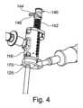
図1~3を参照すると、一例による汎用ドリルガイドシステム100が示されている。汎用ドリルガイドシステム100は、汎用ドリルガイド110を特徴とする。汎用ドリルガイド110は、管状ガイド本体120と、ガイド本体120から斜めに延びるハンドル130とを含む。ガイド本体120は、後述するように、ドリルビットを受け入れるための近位開口部123を画定する近位端部122を有する。ガイド本体120はまた、後述するように、ドリルチューブを受け入れるための遠位開口部125を画定する遠位端部124を有する。さらに、ガイド本体120は、ドリルビットがガイド本体120を通ってどれくらい進むかを制限することによって、穿孔深さを制限するドリル止め140を特徴とする。任意選択のナビゲーションスターユニット50が、図1の汎用ドリルガイド110に取り付けられており、これは、調整されて従来のナビゲーションシステムとともに使用することができる。 1-3, a universal
汎用ドリルガイドシステム100はまた、交換可能なドリルチューブ150のセットと、交換可能なドリルビット200のセットとを含む。交換可能なドリルチューブ150のセットは、第1のドリルチューブ150A、第2のドリルチューブ150B、および第3のドリルチューブ150Cを含む。交換可能なドリルビット200のセットは、第1のドリルビット200Aと、第2のドリルビット200Bと、第3のドリルビット200Cとを含む。しかしながら、ドリルチューブ150の数およびドリルビット200の数は、3つに限定されない。全てのドリルチューブ150A、150B及び150C、並びに全てのドリルビット200A、200B及び200Cは、汎用ドリルガイド110に接続可能である。The universal
第1、第2、および第3のドリルビット200A、200B、および200Cは、中空であり、この説明の次のセクションで説明されるように、Kワイヤを保持するように設計された特徴を有する。第1、第2、および第3のドリルビット200A、200B、および200Cも、異なる穿孔直径を有する。各穿孔直径は、特定のサイズのねじ穴を椎体に開けるように構成される。第1、第2、および第3のドリルビット200A、200B、および200Cは、それぞれ、ドリルドライバに取り付けるための近位端部202と、穴を開けるための刃先を有する反対側の遠位端部204とを有する。また、第1、第2、および第3のドリルビット200A、200B、および200Cは、拡大直径部207に隣接する縮小直径部205を有し、急激な移行を形成する。この急激な移行は、近位端部202と遠位端部204との間に位置する停止面206を形成する。停止面206は、ガイド本体120のドリル止め140と協働して、穿孔中にドリルビットが椎体内を進むことができる距離を制限する。停止面206は、ドリルビット200A、200B、および200Cをドリル操作後に取り外す役割も果たす。これについては、別のセクションで説明する。The first, second, and
第1、第2、および第3のドリルチューブ150A、150B、および150Cは、穿孔中に、それぞれ第1、第2、および第3のドリルビット200A、200B、および200Cの前進をガイドするように設計されている。また、第1、第2、および第3のドリルチューブ150A、150B、および150Cは、穿孔中、第1、第2、および第3のドリルビット200A、200B、および200Cを軸方向に安定した状態に保つ。第1、第2、および第3のドリルチューブ150A、150B、および150Cの各々は、ガイド本体120に取り付けるための近位端部152と、穿孔位置において患者に挿入される反対側の遠位端部154とを有する。ドリルチューブ150A、150Bおよび150Cの各々の近位端部152は、後により詳細に記載されるように、ガイド本体120への取り付けを容易にする切り込み157を含む。The first, second, and
第1、第2、および第3のドリルチューブ150A、150B、および150Cは、それぞれ、第1、第2、および第3のドリルビット200A、200B、および200Cを受け入れるように特別にサイズ決めされた内径を有するドリルビット通路156を画定する。したがって、第1、第2、および第3のドリルビット200A、200B、および200Cは、それぞれ、第1、第2、および第3のドリルチューブ150A、150B、および150Cのみと共に作動するように設計される。第1、第2、第3のドリルチューブ150A、150B、150Cの各々、および第1、第2、第3のドリルビット200A、200B、200Cの各々には、選択されたドリルビットに対して適切なドリルチューブをユーザが選択するのを助けるための印が設けられている。任意の種類の印を使用することができる。システム100では、第1のドリルチューブ150Aと第1のドリルビット200Aは、整合印160Aを有し、第2のドリルチューブ150Bと第2のドリルビット200Bは、整合印160Bを有し、第3のドリルチューブ150Cと第3のドリルビット200Cは、整合印160Cを有する。印160A、160Bおよび160Cは、独特で互いに異なり、各ドリルチューブおよびドリルビットの円周の周りの異なる色の帯の形態で現れる。The first, second, and
図4を参照すると、ドリル止め140は、シャフト142と、シャフト142から横方向に延びる停止プレート144とを有する。停止プレート144は、第1、第2、および第3のドリルビット200A、200B、および200Cの遠位部分が停止プレート144を通過できるように十分に広いスロット寸法を有するスロット146を有する。スロット146は、第1、第2、および第3のドリルビット200A、200B、および200Cの停止面206の断面寸法よりも小さい。この構成では、停止プレート144は、第1、第2、および第3のドリルビット200A、200B、および200Cのそれぞれが、それぞれの停止面206が停止プレート144に当接するまで、停止プレート144を通って前進できるように構成されている。このようなとき、ドリルビットは選択されたドリル深さに達し、ガイド本体120を通るドリルビットがさらに前進することが妨げられる。4, the
図5および図6を参照すると、ドリル止め140を上昇または下降させて、所望の穿孔深さ設定を設定することができる。ばね式ロック126がドリル止め140のシャフト142と解除可能に係合し、シャフト142をロックおよびロック解除する。シャフト142は、一側面に一連の円周溝143を有する。ばね式ロック126は、ばねの付勢力下でシャフト142の位置をロックするために、溝143のうちの1つと係合するように構成される。ばね式ロック126は、図5に示すように内側に押し込むことができるリリースボタン127を含む。リリースボタン127を内側に押すと、ばね式ロック126がシャフト142から外れ、シャフト142をガイド本体120に対して上昇または下降させて、深さ設定を設定することができる。深さ設定が一旦設定されると、図6に示すようにリリースボタン127が解除され、ばね式ロック126がばねの付勢力下でシャフト142と係合できるようにする。ばね式ロック126とシャフト142との係合は、ガイド本体120に対するシャフト142の垂直位置をロックし、深さ設定を固定する。5 and 6, the drill stop 140 can be raised or lowered to set the desired drilling depth setting. A spring loaded
汎用ドリルガイド110は、選択された深さ設定の視覚的インジケータをユーザに提供する2セットの印をその外側に有する。第1のセットの印128は、ガイド本体120の側面に垂直方向の一連のマーキング128aを含む。第2のセットの印148は、シャフト142上の垂直方向の一連のマーキング148aを含む。マーキング128a、148aの各々は、ミリメートル単位または他の測定単位の深さに対応する固有の数字でラベル付けされる。マーキング128aは、マーキング148aとは異なる汎用ドリルガイド110の側に向けられる。2つの異なる側に重複してマーキングを配置することは、外科医が汎用ドリルガイド110の片側のみしか見ることができない状況に対応する。The
ガイド本体120は、第1、第2、および第3のドリルチューブ150A、150B、および150Cの各々が、クイックコネクト結合部/クイックフィット接続部により遠位開口部125に接続されることを可能にする自動ドリルチューブ捕捉部170を含む。自動ドリルチューブ捕捉部170によって、ユーザは、ドリルチューブ150A、150Bおよび150Cのうちの1つをガイド本体120内に挿入し、ガイド本体120上のどのロック機構にも触れることなく所定の位置にロックすることができる。ドリルチューブは、自動ロックと係合するまで、遠位開口部125に単純に挿入される。ドリルチューブ150A、150B、150Cの各々は、上述したように、ドリルビットの1つを収容するために異なる内径を有する。しかしながら、ドリルチューブ150A、150Bおよび150Cの全ては、ドリル止め140および自動ドリルチューブ捕捉部170と係合する同じ外形寸法を有する。したがって、ドリルチューブ150A、150Bおよび150Cの全ては、同じように自動ドリルチューブ捕捉部170と相互作用する。The
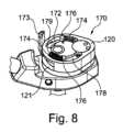
図7および図8を参照すると、自動ドリルチューブ捕捉部170は、ガイド本体120の内側にばね式ロックリング172を備えている。ロックリング172は、ドリルチューブ150A、150Bおよび150Cのそれぞれに形成された切り込み157にスナップ嵌めされるように構成されている。ロックリング172は、ロック方向と解除方向との間でガイド本体120内を回転可能である。一対の圧縮ばね174は、ロックリング172に反時計回りの付勢力を加えて、ロックリング172をロック方向に付勢する。各圧縮ばね174は、ロックリング172の残りの部分から近位方向又は上方に延びるロックタブ176に当接している。7 and 8, the automatic
ロックタブ176及び圧縮ばね174は、一対のスロット178内に収容されている。各圧縮ばね174の一端はスロット178の端壁179に当接し、ばね174の他端はロックタブ176に当接する。この配置では、ユーザが手動でロックリング172を解除方向に回転させない限り、ロックリング172はロック方向に維持される。ロックリング172は、ロックリングに取り付けられているスイッチ173に時計回りの力を加えることによって回転させることができる。スイッチ173は、ガイド本体120内の細長い開口121を通って延在し、ガイド本体120の外側に露出している。The locking
ロックリング172がロック方向にあるとき、図7に示すように、圧縮ばね174は、エネルギーを放出してロックタブ176をそれぞれのスロット178内で反時計回り方向に押し、ロックリング172を反時計回りに回転させる。ロックリング172が解除方向にあるとき、図8に示すように、ロックタブ176は時計回り方向に回転され、蓄積されたエネルギー下でそれぞれのスロット178内の圧縮ばね174を圧縮する。ユーザは、スイッチ173を時計方向に手動で回転させることによって、ロックリング172をロック方向から解除方向に移動させることができる。When the
図9A~図9Dは、ドリルチューブ、この例では第1のドリルチューブ150Aがガイド本体120に挿入され、ロックリング172によって所定の位置にロックされる一連の流れを示す。第2のドリルチューブ150Bおよび第3のドリルチューブ150Cがガイド本体120に挿入されるときにも、同じ流れが生じる。Figures 9A-9D show the sequence in which a drill tube, in this example a
ドリルチューブ150Aは、図9Aに示すように、遠位開口部125を通って、ガイド本体120に形成された通路129内に挿入される。ロックリング172は、最初はロック方向に配置される。ドリルチューブ150Aは、図9Bに示すように、ロックリング172に入るまで通路129内を前進する。ドリルチューブ150Aが進み続けると、ドリルチューブ150Aは、図9Cに示すように、ロックリング172の内面に接触する。ドリルチューブ150Aとロックリング172との間のこの接触は、ロックリング172をロック方向から回転させる。ロックリング172との接触は、通路129内に延びるロックリング172上の面取り部177で生じる。ドリルチューブ150Aの近位端部および側壁は、ドリルチューブ150Aが通路129内で近位方向に前進するときに、面取り部177に接触する。面取り部177の向きは、ドリルチューブ150Aの側壁が、圧縮ばね174の付勢力に逆らって、小さな距離/小さな角度でロックリング172を反時計回り方向に偏向させ、ばね174にさらなるエネルギーを蓄えるように構成される。この偏向は、図9Bで始まり、図9Cで続く。The
ドリルチューブ150Aが通路129内にさらに進められると、ロックリング172は、図9Dに示されるように、ドリルチューブ150A内の切り込み157が面取り部177と位置が合うまで偏向されたままである。この位置合わせが生じると、ロックリング172を偏向させる力が一時的に解除され、圧縮ばね174が拡張し、緩和状態に戻ることを可能にする。この拡張によって、ロックリング172は、ロック方向に向かって回転して戻る。面取り部177は、圧縮ばね174の付勢力の下で、切り込み157内に半径方向内側に向かってスナップする。ロックリング172の軸方向寸法は、ドリルチューブ150Aの軸方向位置がガイド本体120に固定されてロックされるように、スロット157の軸方向寸法と実質的に等しい。As the
図10は、ロック方向におけるロックリング172を示す断面を示す。切り込み157と係合するロックリング172の部分は、円形である。図11は、解除方向におけるロックリング172を示す断面を示す。この状態では、ロックリング172のどの部分も切り込み157内まで延在していない。これら2つの図から分かるように、スイッチ173を圧縮ばね174の付勢力に逆らって反時計方向に回転させることによって、ガイド本体120からドリルチューブ150Aを取り外すことができる。この回転により、図11に示すように、切り込み157から面取り部177を移動させる。この状態では、ドリルチューブ150Aはもはやロックリング172によって軸方向に拘束されず、ガイド本体120から引き出すことができる。10 shows a cross section of the
ドリルビット200A、200B、200Cはそれぞれ、ドリルチューブ150A、150B、150Cの内径に対応する外径を有する。ドリルビット200A、200Bおよび200Cの各々は、ドリルチューブ150Aがガイド本体120に取り付けられているとき、ドリル止め140の上方からドリルチューブ150Aの遠位端部を越えて延びるのに十分な長さである。
穿孔が完了した後、ドリルチューブとドリルビットを所定の位置に残したまま、ドリルドライバと汎用ドリルガイド110を操作側から取り外す必要がある場合がある。これは、ドリル止め140が図1に示すようにドリルビットと係合しているので、技術的な課題となり得る。したがって、汎用ドリルガイド110は、汎用ドリルガイド110がドリルチューブから解除されるときに、ドリル止め140を反時計回りに、ドリルビットから離れるように回動させる機構を含む。これは、図12および図13に示すように、ロックリング172をドリル止め140のシャフト142と相互接続するカム機構190によって達成される。After drilling is completed, it may be necessary to remove the drill driver and the
ロックリング172は、シャフト142の底部のカム追従ピン145を駆動するカムスロット181を含む。この配置では、ロックリング172の時計回り(または図では左)の回転は、シャフト142およびドリル止め140を同時に反時計回り(または図では右)に回転させ、ドリル止め140をドリルビットから離れるように移動させ、ドリルチューブおよびドリルビットが患者の体内に残る一方、汎用ドリルガイド110は、ドリルチューブから離れて持ち上げられ得る。汎用ドリルガイド110をドリルチューブ150Aから離して持ち上げるプロセスを図14および図15に示す。The
ロックリング172上のスイッチ173は、時計回りまたは左に向けて回転されることが図14から分かる。これにより、ドリル止め140が反時計回りまたは右に回動する。ドリル止めをドリルビット200Aから係合解除させる間、図15に示すように、汎用ドリルガイド110は、阻害されることなくドリルチューブ150Aおよびドリルビットから離れて持ち上げられることができる。It can be seen from FIG. 14 that the
Kワイヤ保持付き中空ドリル
前述のように、第1、第2、および第3のドリルビット200A、200B、および200Cは、中空になっており、Kワイヤを保持するように設計された特徴を有する。ドリルビット200A、200Bおよび200Cは、一般に同じであるが、いくつかの違いがある。ドリルビット200A、200B、200Cの外径は異なり、各外径は異なるサイズの穴を開けるように構成されている。ドリルビット200Aの内径は、ドリルビット200B及び200Cの内径よりも小さく、ドリルビット200Aの内径は、直径1.0mmのKワイヤがドリルビット200Aを通過できるように構成されている。ドリルビット200B及び200Cの内径はより大きく、各々は、直径1.5mmのKワイヤがドリルビット200B、200Cを通過できるように構成されている。ドリルビット200A、200Bおよび200Cはまた、その外側に異なる色の印を有し、ユーザが各ドリルビットを対応するドリルチューブとペアにするのを助ける。 Hollow Drill with K-Wire Retention As previously mentioned, the first, second and
ここで図16を参照して、同じ説明がドリルビット200Bおよび200Cに適用されるという理解のもと、ドリルビット200Aを有するドリルビットアセンブリについて、より詳細に説明する。ドリルビット200Aは、Kワイヤ300とともに示されている。Kワイヤ300は、近位端部202から遠位端部204までドリルビット200Aを通って延びる通路208を通って延びる。Kワイヤ300は、近位端部302と、遠位端部304と、近位端部と遠位端部との間に延在するワイヤ本体306とを有する。遠位端部304は、選択された位置で骨内に穿孔できる鋭い尖った端部308を有する。Kワイヤ300が骨内に挿入されると、外科医は、中空骨スクリュ、ドリルビット、または他の器具をKワイヤ上に通し、それを選択された位置に前進させて手術を行うことができる。16, the drill bit assembly having
Kワイヤ300は、ドリルビット200Aよりも著しく長い。従ってKワイヤ300は、Kワイヤの近位端部302が近位方向へ、ドリルビット200Aの近位端部202の外側に突出する状態で、ドリルビット200Aを貫通して延びることができる。同時にKワイヤ300は、Kワイヤの遠位端部304が遠位方向へ、ドリルビット200Aの遠位端部204の外側に突出する状態で、ドリルビット200Aを貫通して延びることができる。Kワイヤ300は、Kワイヤとドリルビットを一緒に骨内に挿入することを可能にするアセンブリとして、ドリルビット200Aの内側に取り外し可能に固定可能である。The K-
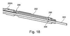
図17および図18を参照すると、ドリルビットに内蔵されている保持機構290によって、穿孔中にKワイヤ300がドリルビット200Aの内側に取り外し可能に固定される。保持機構290は、穿孔中にドリルビット200Aに対してKワイヤが軸方向に前進すること防ぐために、Kワイヤ300と係合するように構成される。この保持はKワイヤ300およびドリルビット200Aが一緒に挿入され、骨内に同じ量だけ前進することを確実にする。保持機構290はまた、ドリルビット200Aに加えられたトルクをKワイヤ300に伝達することを可能にする。従って、保持機構が係合されると、Kワイヤ300とドリルビット200Aは一体となって回転する。トルクドライバは、Kワイヤ300とドリルビット200Aに一体でトルクを加えて、Kワイヤを骨にしっかりと挿入し、骨スクリュ用のパイロット穴を形成することができる。パイロット穴が開けられると、ドリルビット200AはKワイヤを骨内に残しながら、Kワイヤ300から係合解除され、患者から取り外され得る。17 and 18, the K-
保持機構290はKワイヤ300の外側部分上のロック溝308と解除可能に係合するように構成された保持クリップ292を含む。本開示によるロック溝及び保持クリップは、様々な形態及び幾何学的形状を有することができる。例えば、ロック溝は、Kワイヤの一部の周囲に延在することができ、又はKワイヤを円周方向に完全に囲むことができる。保持クリップは、ドリルビットの外側にクリップ留めされるか、またはドリルビットと一体に形成することができる。保持クリップは、ドリルビット内でKワイヤが軸方向に変位することを制限するために、ロック溝内に押し込むことができる内向きに延びる保持端部を有することもできる。The
保持クリップ292は、保持クリップをドリルビット200Aに取り付けるハブ部分294を有する。保持クリップ292はまた、ハブ部分294の反対側に保持端部296を有する。保持端部296は、ドリルビット200の側壁を通って半径方向内側に向かって突出し、Kワイヤ300のロック溝308と係合する。The retaining
本開示によるKワイヤは、トルクがドリルビット/保持クリップからKワイヤに伝達されることを可能にする幾何学的形状をロック溝内に有することができる。例えば、Kワイヤは、溝内のその外側の一部に、保持クリップの保持端上の平坦な縁部と係合する平坦な表面を有することができる。図19は、溝内に四面四角形の部分310を有するロック溝308を有するKワイヤ300の一例を示す。Kワイヤ300は、ドリルビット200Aのような、前述の例のいずれかによるドリルビットに形成された保持クリップと共に動作することができる。A K-wire according to the present disclosure can have a geometry in the locking groove that allows torque to be transferred from the drill bit/retaining clip to the K-wire. For example, the K-wire can have a flat surface on its outer portion in the groove that engages with a flat edge on the retaining end of the retaining clip. FIG. 19 shows an example of a K-
本開示によるロック溝は、近位端壁および遠位端壁によって境界付けられ得る。近位端壁および遠位端壁は、周囲のドリルビットに対するKワイヤの軸方向の変位を制御する様々な幾何形状を有することができる。図19の例では、ロック溝308は、近位端壁312と遠位端壁314とを有する。遠位端壁314はKワイヤ300の長手方向軸301に対して実質的に垂直である。これは、保持クリップ292がロック溝308に係合されたときに保持クリップ292の保持端部296に当接することができる停止部316を形成し、それによってKワイヤ300が遠位方向に相対変位すること防止する。遠位端壁314とは対照的に、近位端壁312は、長手方向軸301に対して鋭角に延びる傾斜面318からなる。傾斜面318は傾斜した部分320を形成し、穿孔が完了した後にドリルビット200AをKワイヤ300から引き抜く間に、保持クリップ292の保持端部296が徐々に外側に偏向し、ロック溝308から摺動して外れることを可能にする。The locking groove according to the present disclosure may be bounded by a proximal end wall and a distal end wall. The proximal end wall and the distal end wall may have various geometries that control the axial displacement of the K-wire relative to the surrounding drill bit. In the example of FIG. 19, the locking
保持クリップ292は、ロックモードおよび解除モードで動作可能である。ロックモードでは、保持端部296は、図18に示すように、ロック溝内で内側に向かって押圧保持される。これにより、穿孔中にドリルビット200に対するKワイヤ300の軸方向位置がロックされる。穿孔が完了した後、保持端部296上の内向きの力を取り除き、保持クリップ292を解除モードに留めることができる。解除モードでは、ドリルビットがKワイヤから完全に取り外されるまで、ドリルビット200をKワイヤ300に対して近位方向に移動させることが可能である。これにより、Kワイヤ300をその後の使用のために患者の体内に残したまま、ドリルビット200Aを患者から引き抜くことができる。The retaining
図20を参照すると、保持クリップ292は、ペンのポケットクリップと同様に、ドリルビットの丸い外側にクリップ留めするように構成された部分的に円筒形のハブ部分294を有する。保持クリップ292はまた、ハブ部分294と保持端部296との間に可撓性アーム295を有する。可撓性アーム295は、ドリルビットがKワイヤから引き出されるときに、保持端部296が蓄積されたエネルギーの下で半径方向外側にたわむことを可能にする。保持端部296は、ドリルビットがKワイヤから取り外されるとき、外側の位置に偏向されたままである。ドリルビットがKワイヤから取り外されると、保持端部296は、半径方向内側に向かってスナップして図20に示される緩和状態に戻る。20, the retaining
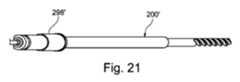
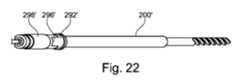
保持クリップの保持端部に半径方向内側に向かって力を加えて、保持クリップを押してロック溝との係合モードで保持することができる。内側向きの力は、多くの方法で加えることができる。図21および図22は、ドリルビット200’および可動スリーブ298’を備えたドリルビットアセンブリの別の例を示す。可動スリーブ298’は、第1の位置と第2の位置との間でドリルビット200’の外部上を摺動可能である。第1の位置(図21)では、スリーブ298’は保持端部296’を覆い、内側向きの力を加えて保持クリップ292’を係合モードに保持する。第2の位置(図22)では、スリーブ298’が保持端部296’から外れて動かされ、保持端部296’が外側に撓みKワイヤ300のロック溝から保持クリップ298’が外れることを可能にする。A radially inward force can be applied to the retaining end of the retaining clip to push and hold the retaining clip in engagement mode with the locking groove. The inward force can be applied in a number of ways. FIGS. 21 and 22 show another example of a drill bit assembly with a drill bit 200' and a movable sleeve 298'. The movable sleeve 298' is slidable on the exterior of the drill bit 200' between a first position and a second position. In the first position (FIG. 21), the sleeve 298' covers the retaining end 296' and applies an inward force to hold the retaining clip 292' in engagement mode. In the second position (FIG. 22), the sleeve 298' is moved off the retaining end 296', allowing the retaining end 296' to flex outwardly and disengage the retaining clip 298' from the locking groove of the K-
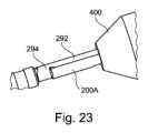
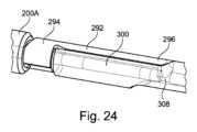
他の例では、別個の器具を使用して、保持クリップをロックしてKワイヤと係合させることができる。図23および図24は、ドリルドライバ400によってドリルビット200Aの保持クリップ292が係合モードに維持される例を示す。ドリルドライバ400は、保持クリップ292の保持端部296上に固定され、保持クリップ292をKワイヤ300の四面ロック溝308内で係合モードに維持するために外力を加える。In other examples, a separate instrument can be used to lock the retaining clip into engagement with the K-wire. FIGS. 23 and 24 show an example in which the
ドリル取外しツール
図25~32を参照すると、一例によるドリル取り外しツール500が示される。ドリル取り外しツール500は、穴が開けられた後に骨から中空ドリルビットを取り外す一方で、Kワイヤを骨内の適所に残すように設計される。ドリルビットがKワイヤから取り外されると、骨スクリュをKワイヤの上で進め、ねじ穴内に進めることができる。ドリル取り外しツール500は、ドリルビット、ドリルチューブ、およびKワイヤの任意の組み合わせと使用することができる。この説明の目的のために、ドリル取り外しツール500は、先に説明した同じドリルビット200A、ドリルチューブ150AおよびKワイヤ300と共に使用して説明される。 Drill Removal Tool Referring to Figures 25-32, an example
ドリル取り外しツール500は、第1の支持端部510と、第2の支持端部520と、第1の支持端部510と第2の支持端部520との間に延在する歯付きラック530とを含む。第1の支持端部510はKワイヤ300を固定するように動作可能なワイヤクランプ540を含む。第2の支持端部520は、ドリルチューブ150Aの周囲にぴったりと嵌合するように構成されたC字型基部522を含む。ドリルビット取り外し部570は、第1の支持端部510と第2の支持端部520との間の歯付きラック530上で軸方向に変位可能である。The
図26~図29を参照すると、ワイヤクランプ540は、非ロック状態においてKワイヤ300の露出端部上を通過し、続いて、ロック状態においてKワイヤ300をクランプするように構成される。ワイヤクランプ540は、第1の支持端部510から延在する中空ハウジング542を含む。中空ハウジング542は、近位端部546と、遠位端部548と、近位端部546と遠位端部548との間の収束部549とを有するクランプ通路544を画定する。近位端部546は雌ねじ547を有する。ノブ550は、ダイヤル552と、クランプ通路544内の雌ねじ547と嵌合する雄ねじ557を備えたシャフト554とを含む。ノブ550は、クランプピン560を軸方向に受け入れる貫通孔558を画定する。クランプピン560は、貫通路562と、その遠位端部566にくさび形コレット564とを画定する。コレット564は、遠位端部566に向かって徐々に減少する外径を有し、収束部549の形状に適合する円錐形状の突起を形成する。貫通路562は、Kワイヤ300を受け入れるように適合された内径を有する。26-29, the
ノブ550は、ロック解除状態とロック状態との間でノブ軸551を中心に回転可能である。ノブ軸551は、貫通孔558および貫通路562と同軸上で整列する。図27は、ノブ550が非ロック状態にあることを示し、図28は、ノブがロック状態に回転された後の状態を示す。雌ねじ547および雄ねじ557は、ノブが回転されるときに、ノブ550の軸方向変位を促進する。クランプピン560は、ノブ550内で軸方向に固定され、ノブ550の遠位端部556は、コレット564に当接する。この配置では、ノブ550およびクランプピン560は、ノブが回転されると、クランプハウジング544内で軸方向に、かつ一体となって移動する。雌ねじ547および雄ねじ557は、ダイヤル552の時計回り方向CWの回転によって、ノブ550およびコレット564が、収束部549内に遠位方向に移動するように向けられる。収束部549のテーパ形状は、クランプピン560が遠位方向に移動するときにコレット564に内側向きの力を加え、Kワイヤ300をロック状態でロックするようにコレット564を圧縮する。The
ドリル取り外しツール500はKワイヤ300、ドリルビット200A、およびドリルチューブの上に2段階で取り付け可能である。第1の段階では、ワイヤクランプ540がKワイヤに通される。ワイヤクランプ540をKワイヤ300に通すために、ノブ550は、コレット564がクランプ通路544の収束部549内で圧縮されないように、ロック解除状態まで反時計回りに回転される。一旦、Kワイヤ300の近位端部がワイヤクランプ540を通過すると、第2の支持端部520およびC字型基部522は、図26の湾曲した矢印で示される方向にドリルチューブ150Aの方へ回動される。C字型基部522は、C字型基部の開口523が、ぴったりとフィットしてドリルチューブ150Aを受け入れるまで回動される。The
図30を参照すると、ドリルビット取り外し部570は、貫通スロット574を画定するフォーク形状のアンビル572を含む。貫通スロット574は、クランプ通路544および開口523と位置合わせされ、ドリル取り外しツール500の3つのすべての部分を通る直線通路を形成する。アンビル572は、貫通スロット574の上方に平坦なフォークリフト面576を有する。貫通スロット574およびフォークリフト面576は、先に述べたように、停止面206の下でドリルビット200Aと係合するように構成される。貫通スロット574は、ドリルビット200A上の縮小直径部205よりもわずかに大きいが、拡大直径部207よりも小さい直径を有する丸い端部575を有する。したがって、アンビル572は、フォークリフト面576が停止面206に対して下方または遠位に位置決めされた状態で、ドリルビット200Aの縮小直径部205を貫通スロット574内に受け入れるように構成される。この位置では、フォークリフト面576は、図32に示すように、停止面206において拡大直径部207に当接する。30, the drill
ドリルビット取り外し部570は、アンビル572に接続されたスリーブ573を含む。スリーブ573は、ラック530を取り囲み、アンビル572をC字型基部522と相互接続する。ピニオンハウジング582は、スリーブ573の一方の側から延在し、ピニオン584を含む。ピニオン584は、ピニオンハウジング582とラック530との間の開口部を通してラック530の歯531と噛み合うか、または係合する複数のギア歯585を有する。ホイールハンドル586は、ピニオン584に取り付けられ、ピニオンハウジング582の外側に延在する。ホイールハンドル586およびピニオン584は、ピニオンハウジング582に対して一体となって回転可能である。この配置では、ホイールハンドル586を回転させて、ドリルビット取り外し部570をラック530に沿って上下に移動させることができる。The drill
図30及び図31を参照すると、ばね式爪部587がラック530の歯531と解除可能に係合する。爪部587は、ばね588によって歯531と係合するように付勢されている。爪部587の歯531との係合は、ドリルビット取り外し部570がラック530に沿って変位した後に自動的に生じ、アンビル572の位置を維持するためにラック530に対するドリルビット取り外し部570の位置をロックするように働く。爪部587は、ばね588の付勢力に逆らって歯531との係合から外れて回動可能であり、爪部587を解除してドリルビット取り外し部570がラック530上で移動できるようにする。爪部587は、爪部587から延びるタブ589を押し下げることによって、歯531との係合から外れるように回動させることができる。必要に応じて、ばね588の強度は、爪部587をラック530に対して保持するが、ラチェットのようにホイールハンドル586が回されると、爪部587がラック530に沿って動くことを可能にするように設計され得る。あるいは、ばね588の強度は、ホイールハンドル586が回されたときには爪部587が歯531から外れず、ユーザがタブ589を押し下げたときにのみ歯531から外れるように選択することができる。30 and 31, a spring-loaded
ピニオン584は、ホイールハンドル586を正面から見るときに、ラック530の左側に配置される。この配置では、時計回り方向CWへのホイールハンドル586を回転させることによって、アンビル572を上方に、または第1の支持端部510に向かって上昇させる。これにより、フォークリフト面576は、ドリルビット200Aの停止面206に接触して上向きにまたは近位方向に支え、ドリルビット200Aを近位方向に変位させる。従って、ドリルビット200Aを患者から取り外すために、Kワイヤ300を取り外さずに、ユーザは、まず、ワイヤクランプ540をロックしてKワイヤ300を軸方向に固定する。次いで、ユーザは、ホイールハンドル586を時計回りに回転させて、ドリルビット200AをKワイヤ300に対して近位方向に移動させる。これはKワイヤ300を変位させず、Kワイヤを所定の位置に保持しながら、ドリルビット200Aを患者から引き抜く効果を有する。ホイールハンドル586は、ドリルビット200Aの遠位端部204が患者から取り外されるまで回転される。ドリルビット200Aがもはや患者の体内にいなくなると、ワイヤクランプ540がロック解除され、C字型基部522がドリルチューブ150Aから取り外される。これにより、ドリル取り外しツール500はKワイヤ300に沿って再び移動することができる。次いで、ドリルビット200AもKワイヤ300から取外されるように、フォークリフト面576がドリルビット200Aを支持した状態で、ドリルビット取り外しツール500がKワイヤ300から外れて持ち上げられる。ドリルビット取り外しツール500がKワイヤ300から取り外された後、ドリルチューブ150Aは、任意の組織拡張器と同様に、患者から取り外され得る。この例では、ドリルチューブ150Aは、複数の入れ子式拡張器を通って延びており、最も外側の拡張器Dが図32に示されている。The
代替のMIS技術では、ドリルビット200AをKワイヤ300なしで骨内に挿入することができる。このような場合、ドリルビット200Aを通してKワイヤ300を骨内に挿入するためにドリル取り外しツール500は使用され得る。この技術を開始するために、前述の実施形態のような汎用ドリルガイドがナビゲーションユニットに取り付けられ、調整される。ドリル止めの高さが設定され、適切なドリルチューブが汎用ドリルガイドに取り付けられる。次に、閉塞具を汎用ドリルガイドおよびドリルチューブに挿入し、所定の位置にロックする。次に、汎用ドリルガイドおよび閉塞具は、患者内の所望の穿孔位置まで挿入される。次に、閉塞具を汎用ドリルガイドおよびドリルチューブから取り外し、皮質パンチと交換する。皮質パンチは、皮質層に開始穴を形成するために使用され、次いで取り外される。次いで、適切なドリルビットをドライバに取り付け、汎用ドリルガイドに挿入し、ドリルチューブを通して前進させ、骨に穴をあける。ドリルビットが骨に挿入されると、汎用ドリルガイドがドリルチューブから取り外され、ドリルビットとドリルチューブはそのまま残される。In an alternative MIS technique, the
組織拡張器Dは、拡張器ハンドルに取り付けられ、ドリルチューブを取り囲む組織に接触するまで、ドリルチューブ上を前進する。次に、拡張器を押し、回転させて組織を拡張させる。次に、組織プロテクタPが拡張器上を前進する。次に、Kワイヤを、ドリルビットを通して骨に挿入することができる。A tissue expander D is attached to the expander handle and advanced over the drill tube until it contacts the tissue surrounding the drill tube. The expander is then pushed and rotated to expand the tissue. A tissue protector P is then advanced over the expander. A K-wire can then be inserted through the drill bit and into the bone.
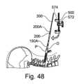
図46~52を参照すると、ドリルビット200Aを通してKワイヤ300を挿入するための1つのプロセスが示されている。第1の工程ではKワイヤ300がドリル取り外しツール500に取り付けられる。ノブ550は、ロック解除位置まで回転され、Kワイヤ300は、図46の矢印で示される方向にノブを通って挿入される。Kワイヤ300は、Kワイヤの長いマーキング303がドリル取り外しツール500によって完全に覆われるまで、ノブ550を通って前進する。Kワイヤ300がドリル取り外しツール500を通って適切な位置まで前進すると、ノブ550は、図47の矢印で示されるようにロック位置まで回転されてKワイヤをワイヤクランプ540内にロックする。Referring to Figures 46-52, one process for inserting the K-
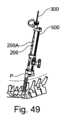
ドリル取り外しツール500及びKワイヤ300は、ドリルビット200Aの近位端部202の上方に配置される。次にKワイヤ300は、ドリルビット200A内に案内される。ドリル取り外しツール500の底部は、図48に示すように、ドリルビットがアンビル572の貫通スロット574内に受け入れられるまで、ドリルビット200Aおよび拡張器Dに向かって回動される。ドリル取り外しツール500は、アンビル572が停止面206の下に位置することを確認しながら回動される。ドリル取り外しツール500がドリルビット200Aおよび拡張器Dに取り付けられると、ノブ550は、図49に示される方向にロック解除位置まで回転される。The
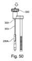
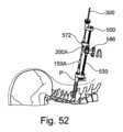
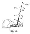
Kワイヤ300は、図50に示されるように、ドリルビット200A内へ下方に進められる。一旦長いマーキング303がドリルビット200Aによって完全に覆われると、ノブ550は、図51に示すようにロック位置まで回転される。次に、図52に示すように、ホイールハンドル586を回転させて、アンビル572を歯付きラック530に対して上方に移動させ、ドリルビット200Aを骨から引き出す。ドリルビット200Aが骨から引き出されると、ドリル取り外しツール500およびドリルビットを持ち上げて取り外すことができる。次に、図53に示すように、ドリルチューブ150Aおよび拡張器DをプロテクタPから取り外すことができる。The K-
Kワイヤ保持付き骨スクリュドライバ
図33~図41を参照すると、一例による骨スクリュドライバ600を有する骨スクリュドライバセンブリが示されている。骨スクリュドライバ600は、Kワイヤが前方(すなわち、遠位)に前進することを防止しつつ、骨スクリュをKワイヤ上で前進させ、骨スクリュを骨内に進めるように設計される。これを達成するために、骨スクリュドライバセンブリはKワイヤ保持モジュール700を特徴とする。この説明の目的のために、骨スクリュドライバ600およびKワイヤ保持モジュール700は、先に説明したのと同じKワイヤ300と共に使用して説明される。 Bone Screwdriver with K-Wire Retention Referring to Figures 33-41, there is shown a bone screwdriver assembly having a
骨スクリュドライバ600は、近位端部602と、近位端部602の反対側の遠位端部604と、近位端部602と遠位端部604との間の長手方向貫通路606とを画定するシャフト601を有する。通路606は、骨スクリュドライバ600がKワイヤ300の近位端部上を通過しKワイヤ300の遠位端部に向かって前進することができるように構成される。近位端部602は、ハンドル603が取り付けられる取り付け機構(図示せず)を有する。取り付け機構は、六角形のシャフトを含むがこれに限定されない、ハンドルを受け入れるための任意の適切な構造とすることができる。ハンドル603は、従来のスクリュドライバのように、骨スクリュドライバ600を操作するユーザによって把持され、回転されるように構成される。遠位端部604は、椎弓根スクリュアセンブリのロッド受容構成要素内の雌ねじと嵌合するように構成された雄ねじ605を有する。シャフト601の回転を容易にし、雄ねじ605をロッド受け部品にねじ込むために、ノブ607がシャフト601に設けられている。The
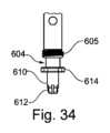
図34および図35を参照すると、遠位端部604はドライバ先端部610を有する。ドライバ先端部610は、骨スクリュの頭部に、同様に成形された凹部に嵌合するヘクサロビュラ延長部612を有する。ドライバ先端部610はまた、延長部612に対して近位に配置された一対の舌部614を有する。舌部614は、雄ねじ605がロッド受け部品の雌ねじにねじ入れされるときに、ロッド受け部品内の直径方向に対向したスロット内にスライドして入るように構成されている。この構成では、舌部614は、固定ロッドが配置される位置を占める。34 and 35, the
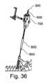
Kワイヤ保持モジュール700は、近位端部712と、遠位端部714と、近位端部712と遠位端部714との間に延在する通路716とを有するハウジング710を含む。通路716は、骨スクリュドライバ600の通路606と位置合わせされる。この配置では、骨スクリュドライバ600およびKワイヤ保持モジュール700は、一体としてKワイヤ300上を進むことができる。図36は、埋め込まれたKワイヤ300上を前進する最中の(ハンドル603が取り付けられていない)骨スクリュドライバ600を示す。ドライバ先端部610は、Kワイヤ300の上を同様に通る中空多軸スクリュアセンブリ800とタブ保護スリーブ850とに固定される。The K-
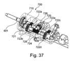
図37を参照すると、Kワイヤ保持モジュール700は、ハウジング710内に収容されたローラアセンブリ720を有する。ローラアセンブリ720は、係合解除モードおよび係合(または駆動)モードで動作可能である。係合解除モードでは、ローラアセンブリ720は、Kワイヤ保持モジュール700及び骨スクリュドライバ600がKワイヤ300の長さに沿って自由に進むことを可能にする。係合モードでは、ローラアセンブリ720はKワイヤ300と係合し、骨スクリュドライバ600が多軸スクリュアセンブリ800を遠位方向に前進すると、Kワイヤ300を、ハウジング710を介して近位方向に送る。Referring to FIG. 37, the K-
ローラアセンブリ720は、骨スクリュドライバ600のシャフト601に取り付けられた第1の平歯車722aと、第1の平歯車722aに嵌合した第2の平歯車722bとを有している。また、ローラアセンブリ720は、第4の平歯車722dと嵌合するシャフト601上の第3の平歯車722cを含む。第2の平歯車722bおよび第4の平歯車722dは、シャフト601と平行に延びる二次シャフト721に取り付けられている。二次シャフト721は、第5の平歯車722eと嵌合したウォームギヤ724を有する。第5の平歯車722eは、第5の平歯車722eに固定された第1のローラ726に取り付けられており、第5の平歯車722eと第1のローラ726とが一体となって回転するようになっている。第2のローラ728は、第1のローラ726とは反対側のKワイヤ300と係合する位置で第1のローラ726に隣接して配置されている。The
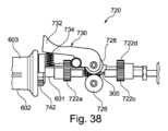
図38~図41を参照すると、ローラアセンブリ720の係合および係合解除は、レバーアセンブリ730によって制御される。レバーアセンブリ730は、圧縮ばね734によって係合モードに向かって付勢されるばね式レバー732を含む。図38は、Kワイヤ300上を前進する直前のローラアセンブリ720の構成要素を示している。レバー732は、完全に拡張されたばね734によって係合モードに位置決めされる。このモードでは、第1および第2のローラ726、728は、互いに近接して配置され、それらの間の隙間はほとんどまたは全くない。ローラアセンブリ720をKワイヤ300の上で前進させるために、レバー732は、図40に示すようにKワイヤに向かって内側に押圧される。これにより、第1および第2のローラ726、728が離れるように動き、ローラアセンブリ720がKワイヤ300上を進むことができる。Kワイヤ300が第1および第2のローラ726、728の間に受け入れられると、レバー732を解除して、ローラをKワイヤと直接係合させるばね734の付勢の下でローラアセンブリ720を係合モードに戻すことができる。38-41, engagement and disengagement of the
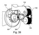
多軸スクリュアセンブリ800は、骨スクリュドライバ600の近位端部602に時計回りのトルクを加えることによって、Kワイヤ300上で骨内に進められる。ローラアセンブリ720が係合モードにある状態で、スクリュドライバ600の近位端部602に時計回りのトルクが加えられると、ローラアセンブリ720は、ハウジング710を介してKワイヤ300を近位方向に送る。シャフト601の時計回りの回転により、第1の平歯車722aおよび第3の平歯車722cが時計回りに回転し、これにより第2の平歯車722cおよび第4の平歯車722dを介して二次シャフト721にトルクが付与される。二次シャフト721およびウォームギヤ724は、反時計回り方向に回転し、これにより、第5の平歯車722eにトルクが付与される。第5の平歯車722eは、第1のローラ726を第1の方向に駆動する。第2のローラ728は、Kワイヤ300に係合するように付勢され、第1の方向とは逆の第2の方向に回転する。第1及び第2のローラ726、728の外面は、Kワイヤ300の表面を把持して、Kワイヤをハウジング710に対して近位方向に引っ張り、その結果、Kワイヤ300は、多軸スクリュアセンブリ800が骨内に遠位方向に進められるときに、近位方向に送られる。The
Kワイヤ300が遠位方向にハウジング710を通して送られることは、ラチェットホイール742および爪部744によって防止される。爪部744は、図39に示すように、ラチェットホイール742と係合して、シャフト601がハウジング710に対して反時計回りに回転されないようにする。これにより、ハウジング710は、Kワイヤを遠位側に送る逆方向に第1および第2のローラ726、728を回転させることになる。爪部744は、図41に示されるように、レバー732をばね724に対して内側に向けて押し付けることによって、ラチェットホイール742との係合から外れて回動され得る。これは、ローラアセンブリ720を非係合モードに切り替えてKワイヤ300を解除し、Kワイヤ300を遠位側に前進させる危険なしに、骨スクリュドライバ600およびKワイヤ保持モジュール700をKワイヤ300から取り外すことを可能にする。The K-
本開示によるKワイヤ保持モジュールは、タッピングおよび駆動のための器具を含むがこれに限定されない、異なる種類の器具に着脱自在に接続可能なモジュラーユニットとすることができる。本実施例では、Kワイヤ保持モジュール700は、図33に示されるクイックフィット接続部650によって骨スクリュドライバ600に着脱可能に接続される。骨スクリュドライバ600のシャフト601は、六角ドライブ、1/4インチドライブ、または回転を制御するAOドライブとすることができるクイックフィット接続部650を使用して、ハウジング710内にスナップ嵌めされる。The K-wire retention module according to the present disclosure can be a modular unit that can be removably connected to different types of instruments, including but not limited to instruments for tapping and driving. In this example, the K-
本開示による骨スクリュドライバは、骨スクリュの挿入を補助するための様々なタイプの印を含むことができる。例えば、シャフト601は、汎用ドリルガイド110上のものと同様に、深さマーキングを提供する間隔を開けた線を有することができる。深さマーキングは、骨スクリュの先端が進む深さの視覚的表示をユーザに提供することができる。骨スクリュドライバはまた、滅菌を補助するための様々な特徴を含み得る。例えば、シャフト601は、オートクレーブ処理および洗浄中に蒸気がシャフト601の内部に入ることを可能にする一連の開口611を有する。Bone screwdrivers according to the present disclosure can include various types of markings to aid in the insertion of the bone screw. For example, the
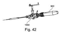
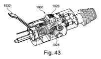
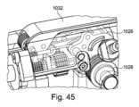
図42~図45は、別の実施形態による代替の骨スクリュドライバ900およびKワイヤ保持モジュール1000を示す。Kワイヤ保持モジュール1000は、Kワイヤ保持モジュール700に類似しているが、ピンチレバー1032およびピンチローラ1026、1028を特徴とする。ピンチレバー1032は、通常、図43及び図44に示すように、ピンチローラ1026、1028を離すために開位置にある。ピンチレバー1032は、図45に示されるように、閉位置に動かされて、Kワイヤ300に対してローラと係合することができる。ピンチレバー1032は、Kワイヤ300がピンチローラ1026、1028の間に配置された場合にのみ、閉じたままにすることができる(すなわち、駆動部を係合したままにすることができる)。42-45 show an
本明細書に記載の器具は、ステンレス鋼の様々な合金を含むがこれに限定されない様々な材料を使用して製造することができる。合金の等級は、所望の強度、硬度、耐食性、摩耗特性および他の性能基準に基づいて選択することができる。The instruments described herein can be manufactured using a variety of materials, including, but not limited to, various alloys of stainless steel. The grade of alloy can be selected based on the desired strength, hardness, corrosion resistance, wear characteristics, and other performance criteria.
したがって、添付の特許請求の範囲は、本開示の範囲内に入るそのようなすべての変形を包含することが意図される。
以下に、本明細書で開示する技術の特徴を列挙する。
(項目1)
汎用ドリルガイドシステム(100)であって、
各々がドリルビット通路を有する複数のドリルチューブ(150)と、
各々が前記複数のドリルチューブ(150)の各々の前記ドリルビット通路に挿入可能な複数のドリルビット(200)と、
を備え、
前記ドリルビット通路の各々は、他のドリルビット通路のいずれの内径とも異なる内径を有し、
前記複数のドリルビット(200)の各々は、他のドリルビット(200)のいずれの外径とも異なる外径を有し、
前記複数のドリルビット(200)の各々の前記外径は、それぞれ、前記ドリルビット通路の各々の前記内径に対応する、
汎用ドリルガイドシステム。
(項目2)
前記複数のドリルチューブ(150)は、第1のドリルチューブ(150A)と、第2のドリルチューブ(150B)と、第3のドリルチューブ(150C)とを含み、
前記複数のドリルビット(200)は、前記第1のドリルチューブ(150A)に対応する第1のドリルビット(200A)と、前記第2のドリルチューブ(150B)に対応する第2のドリルビット(200B)と、前記第3のドリルチューブ(150C)に対応する第3のドリルビット(200C)とを含む、項目1に記載の汎用ドリルガイドシステム(100)。
(項目3)
前記複数のドリルチューブ(150)の各々は、他のドリルチューブ(150)のいずれとも異なる整合印を有し、
前記複数のドリルビット(200)の各々は、他のドリルビット(200)のいずれとも異なる整合印を有し、
前記ドリルビット(200)の各々の整合印は、それぞれ、前記複数のドリルチューブ(150)の各々の整合印に対応する、項目1又は2に記載の汎用ドリルガイドシステム(100)。
(項目4)
前記汎用ドリルガイドシステム(100)は、汎用ドリルガイド(110)を備え、
前記複数のドリルチューブ(150)は、前記汎用ドリルガイド(110)の開口部(125)に挿入可能であり、
前記複数のドリルチューブ(150)は、同一の外形寸法を有する、項目1から3のいずれかに記載の汎用ドリルガイドシステム(100)。
(項目5)
前記汎用ドリルガイド(110)は、自動ドリルチューブ捕捉部(170)を備え、
前記自動ドリルチューブ捕捉部(170)は、前記複数のドリルチューブ(150)を、クイックフィット接続部により前記汎用ドリルガイド(110)の前記開口部(125)に挿入することを許可する、項目4に記載の汎用ドリルガイドシステム(100)。
(項目6)
前記自動ドリルチューブ捕捉部(170)は、ロック方向と解除方向との間で前記汎用ドリルガイド(110)内を回転可能なロックリング(172)を含む、項目5に記載の汎用ドリルガイドシステム(100)。
(項目7)
前記自動ドリルチューブ捕捉部(170)は、前記ロックリング(172)に付勢力をかけて前記ロックリング(172)を前記ロック方向に付勢する圧縮ばね(174)を含む、項目6に記載の汎用ドリルガイドシステム(100)。
(項目8)
前記自動ドリルチューブ捕捉部(170)は、前記圧縮ばね(174)の前記付勢力に逆らって前記ロックリング(172)を前記ロック方向から前記解除方向に手動で回転させるためのスイッチ(173)を備える、項目7に記載の汎用ドリルガイドシステム(100)。
(項目9)
前記ロックリング(172)は、内側に向かって延びる面取り部(177)を備え、前記面取り部(177)は、前記自動ドリルチューブ捕捉部(170)の前記開口部(125)に挿入された前記ドリルチューブ(150)の側壁が、前記圧縮ばね(174)の前記付勢力に逆らう方向に角度をつけて前記ロックリング(172)を偏向させるように向けられ/構成されている、項目7又は8に記載の汎用ドリルガイドシステム(100)。
(項目10)
前記ドリルチューブ(150)の外周面に形成された切り込みが前記面取り部(177)と位置合わせされるまで、前記ロックリング(172)の偏向が維持される、項目9に記載の汎用ドリルガイドシステム(100)。
(項目11)
前記複数のドリルビット(200)の各々は、複数のKワイヤ(300)のうちの1つを受け入れるためのKワイヤ通路を備え、
前記複数のドリルビット(200)の各々の前記Kワイヤ通路は、他のKワイヤ通路のうちのいずれの内径とも異なる内径を有し、
前記複数のKワイヤ(300)の各々は、他のKワイヤ(300)の外径と異なる外径を有し、
前記Kワイヤ(300)の各々の外径は、それぞれ、前記Kワイヤ通路の各々の内径に対応する、項目1から10のいずれか1項に記載の汎用ドリルガイドシステム(100)。
(項目12)
前記複数のドリルビット(200)の各々は、他のドリルビット(200)の穿孔直径とは異なる穿孔直径を有する、項目1から11のいずれか1項に記載の汎用ドリルガイドシステム(100)。
(項目13)
前記複数のドリルビット(200)のそれぞれは、ドリルドライバに取り付けるための近位端部(202)と、ねじ穴を開けるための切れ刃を有する反対側の遠位端部(204)とを有する、項目1から12のいずれか1項に記載の汎用ドリルガイドシステム(100)。
(項目14)
前記汎用ドリルガイド(110)は、ドリル止め(140)を備え、
前記複数のドリルビット(200)の各々は、近位端部(202)と遠位端部(204)との間に位置する停止面(206)を有し、
前記停止面(206)は、前記ドリル止め(140)と協働して、穿孔中に前記ドリルビット(200)が骨内を進行可能な距離を制限する、項目1から13のいずれか1項に記載の汎用ドリルガイドシステム(100)。
It is therefore intended that the appended claims will cover all such modifications that fall within the scope of this disclosure.
The features of the technology disclosed in this specification are listed below.
(Item 1)
A universal drill guide system (100), comprising:
a plurality of drill tubes (150) each having a drill bit passage;
a plurality of drill bits (200), each insertable into the drill bit passages of each of the plurality of drill tubes (150);
Equipped with
each of the drill bit passages has an inner diameter different from the inner diameter of any of the other drill bit passages;
each of the plurality of drill bits (200) has an outer diameter different from the outer diameter of any of the other drill bits (200);
the outer diameter of each of the plurality of drill bits (200) corresponds to the inner diameter of each of the drill bit passages, respectively;
A versatile drill guide system.
(Item 2)
the plurality of drill tubes (150) includes a first drill tube (150A), a second drill tube (150B), and a third drill tube (150C);
2. The universal drill guide system of claim 1, wherein the plurality of drill bits includes a first drill bit corresponding to the first drill tube, a second drill bit corresponding to the second drill tube, and a third drill bit corresponding to the third drill tube.
(Item 3)
each of said plurality of drill tubes (150) having a registration indicia different from any of the other drill tubes (150);
each of the plurality of drill bits (200) having a registration indicia different from any of the other drill bits (200);
3. The universal drill guide system (100) of claim 1 or 2, wherein an alignment mark on each of the drill bits (200) corresponds to an alignment mark on each of the plurality of drill tubes (150), respectively.
(Item 4)
The universal drill guide system (100) comprises a universal drill guide (110);
the plurality of drill tubes (150) are insertable into openings (125) of the universal drill guide (110);
4. The universal drill guide system (100) of any one of items 1 to 3, wherein the plurality of drill tubes (150) have the same outer dimensions.
(Item 5)
The universal drill guide (110) includes an automatic drill tube capture (170);
5. The universal drill guide system of claim 4, wherein the automatic drill tube capture allows the multiple drill tubes to be inserted into the openings of the universal drill guide via quick-fit connections.
(Item 6)
6. The universal drill guide system of claim 5, wherein the automatic drill tube capture includes a locking ring rotatable within the universal drill guide between a locked orientation and an unlocked orientation.
(Item 7)
7. The universal drill guide system of claim 6, wherein the automatic drill tube capture includes a compression spring that exerts a biasing force on the locking ring to bias the locking ring in the locking direction.
(Item 8)
8. The universal drill guide system of claim 7, wherein the automatic drill tube capture includes a switch for manually rotating the lock ring from the locked orientation to the unlocked orientation against the biasing force of the compression spring.
(Item 9)
9. The universal drill guide system (100) of claim 7 or 8, wherein the locking ring (172) comprises an inwardly extending chamfer (177) that is oriented/configured such that a sidewall of the drill tube (150) inserted into the opening (125) of the automatic drill tube capture (170) biases the locking ring (172) at an angle against the biasing force of the compression spring (174).
(Item 10)
10. The universal drill guide system of claim 9, wherein the deflection of the lock ring is maintained until a notch formed in an outer peripheral surface of the drill tube is aligned with the chamfer.
(Item 11)
Each of the plurality of drill bits (200) includes a K-wire passage for receiving one of a plurality of K-wires (300);
the K-wire passage of each of the plurality of drill bits (200) having an inner diameter different from the inner diameter of any of the other K-wire passages;
Each of the plurality of K-wires (300) has an outer diameter different from the outer diameter of the other K-wires (300);
11. The universal drill guide system (100) of any one of claims 1 to 10, wherein an outer diameter of each of the K-wires (300) corresponds to an inner diameter of each of the K-wire passages, respectively.
(Item 12)
12. The universal drill guide system (100) of any one of claims 1 to 11, wherein each of the plurality of drill bits (200) has a drilling diameter that is different from the drilling diameters of the other drill bits (200).
(Item 13)
13. The universal drill guide system (100) of any one of items 1 to 12, wherein each of the plurality of drill bits (200) has a proximal end (202) for attachment to a drill driver and an opposite distal end (204) having a cutting edge for drilling a screw hole.
(Item 14)
The universal drill guide (110) includes a drill stop (140);
Each of the plurality of drill bits (200) has a stop surface (206) located between a proximal end (202) and a distal end (204);
14. The universal drill guide system (100) of any one of claims 1 to 13, wherein the stop surface (206) cooperates with the drill stop (140) to limit the distance the drill bit (200) can advance into bone during drilling.
Claims (13)
Translated fromJapanese各々がドリルビット通路を有する複数のドリルチューブと、
各々が前記複数のドリルチューブの各々の前記ドリルビット通路に挿入可能な複数のドリルビットと、
を備え、
前記ドリルビット通路の各々は、他のドリルビット通路のいずれの内径とも異なる内径を有し、
前記複数のドリルビットの各々は、他のドリルビットのいずれの外径とも異なる外径を有し、
前記複数のドリルビットの各々の前記外径は、それぞれ、前記ドリルビット通路の各々の前記内径に対応し、
さらに、汎用ドリルガイドと、
ロック方向と解除方向との間で前記汎用ドリルガイド内を回転可能なロックリングを含む自動ドリルチューブ捕捉部と、
を備える、
汎用ドリルガイドシステム。 1. A universal drill guide system, comprising:
a plurality of drill tubes, each having a drill bit passage;
a plurality of drill bits, each insertable into the drill bit passages of each of the plurality of drill tubes;
Equipped with
each of the drill bit passages has an inner diameter different from the inner diameter of any of the other drill bit passages;
each of the plurality of drill bits has an outer diameter different from an outer diameter of any of the other drill bits;
the outer diameter of each of the plurality of drill bits corresponds to the inner diameter of each of the drill bit passages, respectively;
In addition, a general-purpose drill guide and
an automatic drill tube capture including a locking ring rotatable within the universal drill guide between a locked orientation and an unlocked orientation;
Equipped with
A versatile drill guide system.
前記複数のドリルビットは、前記第1のドリルチューブに対応する第1のドリルビットと、前記第2のドリルチューブに対応する第2のドリルビットと、前記第3のドリルチューブに対応する第3のドリルビットとを含む、請求項1に記載の汎用ドリルガイドシステム。 the plurality of drill tubes includes a first drill tube, a second drill tube, and a third drill tube;
2. The universal drill guide system of claim 1, wherein the plurality of drill bits includes a first drill bit corresponding to the first drill tube, a second drill bit corresponding to the second drill tube, and a third drill bit corresponding to the third drill tube.
前記複数のドリルビットの各々は、他のドリルビットのいずれとも異なる整合印を有し、
前記ドリルビットの各々の整合印は、それぞれ、前記複数のドリルチューブの各々の整合印に対応する、請求項1又は2に記載の汎用ドリルガイドシステム。 each of the plurality of drill tubes having an alignment indicia different from any of the other drill tubes;
each of the plurality of drill bits having a registration indicia different from any of the other drill bits;
The universal drill guide system of claim 1 or 2, wherein an alignment mark on each of the drill bits corresponds to an alignment mark on each of the plurality of drill tubes, respectively.
前記複数のドリルチューブは、同一の外形寸法を有する、請求項1から3のいずれかに記載の汎用ドリルガイドシステム。 the plurality of drill tubes are insertable into openings of the universal drill guide;
The universal drill guide system according to claim 1 , wherein the plurality of drill tubes have the same outer dimensions.
一つのドリルチューブが、前記ガイド本体に挿入され、所定の位置にロックされることを許可するクイックコネクト結合部により、前記自動ドリルチューブ捕捉部が、前記複数のドリルチューブのそれぞれを前記開口部に接続することを許可する、請求項4に記載の汎用ドリルガイドシステム。a guide bodyincluding the automatic drill tube capture portion;
5. The universal drill guide system of claim 4, wherein the automatic drill tube capture permitseach of the plurality of drill tubes to be connected to the aperture by a quick connect coupling that permits one drill tube to be inserted into the guide body and locked into place.
前記複数のドリルビットの各々の前記Kワイヤ通路は、他のKワイヤ通路のうちのいずれの内径とも異なる内径を有し、
前記複数のKワイヤの各々は、他のKワイヤの外径と異なる外径を有し、
前記Kワイヤの各々の外径は、それぞれ、前記Kワイヤ通路の各々の内径に対応する、請求項1から9のいずれか1項に記載の汎用ドリルガイドシステム。 each of the plurality of drill bits includes a K-wire passage for receiving one of a plurality of K-wires;
the K-wire passage of each of the plurality of drill bits has an inner diameter different from the inner diameter of any of the other K-wire passages;
Each of the plurality of K-wires has an outer diameter different from the outer diameters of the other K-wires,
10. The universal drill guide system of claim 1, wherein an outer diameter of each of the K-wires corresponds to an inner diameter of each of the K-wire passages, respectively.
前記複数のドリルビットの各々は、近位端部と遠位端部との間に位置する停止面を有し、
前記停止面は、前記ドリル止めと協働して、穿孔中に前記ドリルビットが骨内を進行可能な距離を制限する、請求項1から12のいずれか1項に記載の汎用ドリルガイドシステム。
The universal drill guide includes a drill stop;
Each of the plurality of drill bits has a stop surface located between a proximal end and a distal end;
13. The universal drill guide system of claim 1, wherein the stop surface cooperates with the drill stop to limit the distance the drill bit can advance within bone during drilling.
Applications Claiming Priority (3)
| Application Number | Priority Date | Filing Date | Title |
|---|---|---|---|
| US202062970850P | 2020-02-06 | 2020-02-06 | |
| US62/970,850 | 2020-02-06 | ||
| PCT/EP2021/052718WO2021156394A1 (en) | 2020-02-06 | 2021-02-04 | Universal drill guide system |
Publications (2)
| Publication Number | Publication Date |
|---|---|
| JP2023513884A JP2023513884A (en) | 2023-04-04 |
| JP7640566B2true JP7640566B2 (en) | 2025-03-05 |
Family
ID=74556670
Family Applications (3)
| Application Number | Title | Priority Date | Filing Date |
|---|---|---|---|
| JP2022546708AActiveJP7580471B2 (en) | 2020-02-06 | 2021-02-04 | Drill Removal Tool |
| JP2022546710AActiveJP7580472B2 (en) | 2020-02-06 | 2021-02-04 | General-purpose drill guide system |
| JP2022546711AActiveJP7640566B2 (en) | 2020-02-06 | 2021-02-04 | General-purpose drill guide system |
Family Applications Before (2)
| Application Number | Title | Priority Date | Filing Date |
|---|---|---|---|
| JP2022546708AActiveJP7580471B2 (en) | 2020-02-06 | 2021-02-04 | Drill Removal Tool |
| JP2022546710AActiveJP7580472B2 (en) | 2020-02-06 | 2021-02-04 | General-purpose drill guide system |
Country Status (6)
| Country | Link |
|---|---|
| US (1) | US11759280B2 (en) |
| EP (5) | EP4099923B1 (en) |
| JP (3) | JP7580471B2 (en) |
| CN (3) | CN115066215B (en) |
| ES (5) | ES3032939T3 (en) |
| WO (3) | WO2021156394A1 (en) |
Families Citing this family (7)
| Publication number | Priority date | Publication date | Assignee | Title |
|---|---|---|---|---|
| US12262927B2 (en)* | 2020-12-10 | 2025-04-01 | K2M, Inc. | Screw insertion instrument and methods of use |
| WO2023102423A1 (en)* | 2021-12-01 | 2023-06-08 | Foley Kevin T | Guidewire retention mechanism |
| DE102022104674A1 (en)* | 2022-02-28 | 2023-08-31 | Aesculap Ag | Medical drilling device and medical drilling system |
| CN114704214B (en)* | 2022-06-07 | 2022-09-02 | 西南石油大学 | Drill bit fastening and clamping structure and method |
| US12329418B2 (en) | 2022-07-26 | 2025-06-17 | Globus Medical Inc. | Minimally invasive surgery guide wire capturing instrumentation |
| DE102023118429A1 (en)* | 2023-07-12 | 2025-01-16 | Aesculap Ag | preparation instrument for preparing a bone |
| WO2025064874A1 (en)* | 2023-09-20 | 2025-03-27 | Paragon 28, Inc. | Right angle drill, instrumentation, system and methods of use and assembly |
Citations (3)
| Publication number | Priority date | Publication date | Assignee | Title |
|---|---|---|---|---|
| JP2007502171A (en) | 2003-08-13 | 2007-02-08 | ジンテス ゲゼルシャフト ミット ベシュレンクテル ハフツング | Rapid removal drill guide assembly for bone fixation plates |
| US20180271602A1 (en) | 2010-06-29 | 2018-09-27 | Mighty Oak Medical, Inc. | Patient-matched apparatus and methods for performing surgical procedures |
| US20190269420A1 (en) | 2018-03-05 | 2019-09-05 | Edge Surgical, Inc. | Handheld devices for use in medical procedures |
Family Cites Families (36)
| Publication number | Priority date | Publication date | Assignee | Title |
|---|---|---|---|---|
| GB8708076D0 (en)* | 1987-04-03 | 1987-05-07 | British Aerospace | Nose piece adaptors |
| CA2155422C (en)* | 1993-02-10 | 2005-07-12 | Stephen D. Kuslich | Spinal stabilization surgical method |
| GB9325698D0 (en)* | 1993-12-15 | 1994-02-16 | Richardson James B | Patient-operated orthopedic device |
| US6716215B1 (en)* | 1999-10-29 | 2004-04-06 | Image-Guided Neurologics | Cranial drill with sterile barrier |
| GB0125749D0 (en)* | 2001-10-26 | 2001-12-19 | Black & Decker Inc | Power tool |
| AUPR524901A0 (en)* | 2001-05-24 | 2001-06-21 | Hills Industries Limited | Guide mechanism for power drill |
| US6827722B1 (en)* | 2001-12-11 | 2004-12-07 | Biomet, Inc. | Method and apparatus for use of a guide wire capturing surgical instrument |
| AU2004283727A1 (en)* | 2003-10-23 | 2005-05-06 | Trans1 Inc. | Tools and tool kits for performing minimally invasive procedures on the spine |
| US7207995B1 (en)* | 2004-01-29 | 2007-04-24 | Biomer Manufacturing Corp. | Method and apparatus for retaining a guide wire |
| US7163542B2 (en)* | 2004-03-30 | 2007-01-16 | Synthes (U.S.A.) | Adjustable depth drill bit |
| US8109934B2 (en)* | 2005-02-10 | 2012-02-07 | Zimmer Spine, Inc. | All through one drill guide for cervical plating |
| EP2151202B1 (en)* | 2008-08-04 | 2011-02-16 | BrainLAB AG | Clamping piece for clamping a cannulated drill and a guide wire |
| CA2792997A1 (en) | 2010-03-23 | 2011-09-29 | Geisinger Clinic | Diagnostic device for determining mechanical integrity of bone |
| BR112012026814A2 (en)* | 2010-04-20 | 2016-07-12 | Starrett L S Co | spindle and hollow saw spindle system |
| WO2012046210A1 (en)* | 2010-10-07 | 2012-04-12 | Miami Device Solutions, Llc | Bone plate assembly with guide member |
| MX348238B (en)* | 2011-03-09 | 2017-05-29 | Smith & Nephew Inc | Multiple portal guide. |
| DE102011001446B4 (en)* | 2011-03-21 | 2022-06-23 | Wolfcraft Gmbh | Quick change adapter for a hole saw |
| AU2012282919B2 (en)* | 2011-07-08 | 2017-04-13 | Smith & Nephew, Inc. | Orthopedic instruments |
| EP2849656B1 (en)* | 2012-05-14 | 2017-10-04 | Synthes GmbH | Bone access instrument |
| DE102012104207A1 (en)* | 2012-05-15 | 2013-12-05 | Ulrich Gmbh & Co. Kg | assembly tool |
| EP3158952B1 (en)* | 2012-09-14 | 2019-10-23 | Synthes GmbH | Multihole drill sleeve with protection sleeve |
| US20140088647A1 (en)* | 2012-09-21 | 2014-03-27 | Atlas Spine, Inc. | Minimally invasive spine surgery instruments: spinal rod with flange |
| EP2956072B1 (en)* | 2013-02-13 | 2019-12-18 | Synthes GmbH | Pedicle screw engaging control instrument with a guidewire capturing system |
| US9433445B2 (en)* | 2013-03-14 | 2016-09-06 | DePuy Synthes Products, Inc. | Bone anchors and surgical instruments with integrated guide tips |
| US9254160B2 (en)* | 2013-03-14 | 2016-02-09 | Aesculap Implant Systems, Llc | Driver assembly with guidewire control mechanism |
| US20140276880A1 (en)* | 2013-03-15 | 2014-09-18 | Blackstone Medical, Inc. | Locking assembly for a surgical drill bit guide |
| US9439658B2 (en)* | 2013-05-14 | 2016-09-13 | SpineDriver, LLC | Drill bit package assembly |
| WO2015006296A1 (en)* | 2013-07-09 | 2015-01-15 | Stryker Corporation | Surgical drill having brake that, upon the drill bit penetrating through bone, prevents further insertion of the drill bit |
| US20160199072A1 (en) | 2013-08-19 | 2016-07-14 | Smith & Nephew, Inc. | Bone removal under direct visualization |
| US9427274B1 (en)* | 2013-10-17 | 2016-08-30 | Z'egist Solutions, LLC | Surgical cutting system and method |
| US9427271B2 (en)* | 2014-03-18 | 2016-08-30 | Osteomed Llc | Percutaneous exchange tube and method of use |
| US10080583B2 (en)* | 2014-12-12 | 2018-09-25 | Depuy Mitel, Llc | Dilator for accessing a joint space |
| WO2016204711A1 (en)* | 2015-06-16 | 2016-12-22 | Spine Wave, Inc. | Instrument and system for placing graft, implant and graft material for minimally invasive posterolateral fusion |
| JP2018532498A (en)* | 2015-10-14 | 2018-11-08 | マイティ オーク メディカル、インコーポレイテッド | Patient fitting device and method of performing a surgical procedure |
| US10987116B2 (en)* | 2017-12-15 | 2021-04-27 | Medos International Sarl | Adjustable drill guides and related methods |
| CN208644148U (en)* | 2018-04-24 | 2019-03-26 | 米沃奇电动工具公司 | Electric drill rack |
- 2021
- 2021-02-01USUS17/164,145patent/US11759280B2/enactiveActive
- 2021-02-04ESES21704725Tpatent/ES3032939T3/enactiveActive
- 2021-02-04EPEP21704725.7Apatent/EP4099923B1/enactiveActive
- 2021-02-04WOPCT/EP2021/052718patent/WO2021156394A1/ennot_activeCeased
- 2021-02-04ESES21155339Tpatent/ES2924757T3/enactiveActive
- 2021-02-04ESES21704456Tpatent/ES2960328T3/enactiveActive
- 2021-02-04CNCN202180012140.9Apatent/CN115066215B/enactiveActive
- 2021-02-04EPEP21155339.1Apatent/EP3861940B1/enactiveActive
- 2021-02-04EPEP21155340.9Apatent/EP3861941B1/enactiveActive
- 2021-02-04WOPCT/EP2021/052720patent/WO2021156396A1/ennot_activeCeased
- 2021-02-04ESES21155340Tpatent/ES2992101T3/enactiveActive
- 2021-02-04JPJP2022546708Apatent/JP7580471B2/enactiveActive
- 2021-02-04CNCN202180012885.5Apatent/CN115279285A/enactivePending
- 2021-02-04JPJP2022546710Apatent/JP7580472B2/enactiveActive
- 2021-02-04ESES21704457Tpatent/ES3032867T3/enactiveActive
- 2021-02-04JPJP2022546711Apatent/JP7640566B2/enactiveActive
- 2021-02-04EPEP21704457.7Apatent/EP4099930B1/enactiveActive
- 2021-02-04WOPCT/EP2021/052719patent/WO2021156395A1/ennot_activeCeased
- 2021-02-04CNCN202180012910.XApatent/CN115052536B/enactiveActive
- 2021-02-04EPEP21704456.9Apatent/EP4099925B1/enactiveActive
Patent Citations (3)
| Publication number | Priority date | Publication date | Assignee | Title |
|---|---|---|---|---|
| JP2007502171A (en) | 2003-08-13 | 2007-02-08 | ジンテス ゲゼルシャフト ミット ベシュレンクテル ハフツング | Rapid removal drill guide assembly for bone fixation plates |
| US20180271602A1 (en) | 2010-06-29 | 2018-09-27 | Mighty Oak Medical, Inc. | Patient-matched apparatus and methods for performing surgical procedures |
| US20190269420A1 (en) | 2018-03-05 | 2019-09-05 | Edge Surgical, Inc. | Handheld devices for use in medical procedures |
Also Published As
| Publication number | Publication date |
|---|---|
| CN115052536B (en) | 2023-06-02 |
| CN115052536A (en) | 2022-09-13 |
| WO2021156395A1 (en) | 2021-08-12 |
| ES2924757T3 (en) | 2022-10-10 |
| ES2992101T3 (en) | 2024-12-09 |
| CN115066215A (en) | 2022-09-16 |
| EP3861940A1 (en) | 2021-08-11 |
| EP4099930B1 (en) | 2025-04-02 |
| EP3861941A1 (en) | 2021-08-11 |
| JP2023513883A (en) | 2023-04-04 |
| JP7580471B2 (en) | 2024-11-11 |
| EP4099930A1 (en) | 2022-12-14 |
| JP7580472B2 (en) | 2024-11-11 |
| CN115279285A (en) | 2022-11-01 |
| WO2021156396A1 (en) | 2021-08-12 |
| JP2023513884A (en) | 2023-04-04 |
| WO2021156394A1 (en) | 2021-08-12 |
| EP4099925A1 (en) | 2022-12-14 |
| EP4099925B1 (en) | 2023-07-19 |
| JP2023513882A (en) | 2023-04-04 |
| ES3032867T3 (en) | 2025-07-28 |
| CN115066215B (en) | 2023-08-08 |
| EP3861940B1 (en) | 2022-05-25 |
| ES2960328T3 (en) | 2024-03-04 |
| EP4099923A1 (en) | 2022-12-14 |
| ES3032939T3 (en) | 2025-07-29 |
| EP3861941B1 (en) | 2024-08-21 |
| EP4099923B1 (en) | 2025-04-09 |
| US20210244424A1 (en) | 2021-08-12 |
| US11759280B2 (en) | 2023-09-19 |
Similar Documents
| Publication | Publication Date | Title |
|---|---|---|
| JP7640566B2 (en) | General-purpose drill guide system | |
| US11337736B2 (en) | Driver instruments and related methods | |
| US8123785B2 (en) | Minimally invasive spinal stabilization system | |
| EP4011306B1 (en) | Screw insertion instrument | |
| EP2288303B1 (en) | Minimally invasive spinal stabilization system |
Legal Events
| Date | Code | Title | Description |
|---|---|---|---|
| A521 | Request for written amendment filed | Free format text:JAPANESE INTERMEDIATE CODE: A523 Effective date:20221116 | |
| A621 | Written request for application examination | Free format text:JAPANESE INTERMEDIATE CODE: A621 Effective date:20240122 | |
| A977 | Report on retrieval | Free format text:JAPANESE INTERMEDIATE CODE: A971007 Effective date:20240925 | |
| A131 | Notification of reasons for refusal | Free format text:JAPANESE INTERMEDIATE CODE: A131 Effective date:20241001 | |
| A521 | Request for written amendment filed | Free format text:JAPANESE INTERMEDIATE CODE: A523 Effective date:20241224 | |
| TRDD | Decision of grant or rejection written | ||
| A01 | Written decision to grant a patent or to grant a registration (utility model) | Free format text:JAPANESE INTERMEDIATE CODE: A01 Effective date:20250204 | |
| A61 | First payment of annual fees (during grant procedure) | Free format text:JAPANESE INTERMEDIATE CODE: A61 Effective date:20250220 | |
| R150 | Certificate of patent or registration of utility model | Ref document number:7640566 Country of ref document:JP Free format text:JAPANESE INTERMEDIATE CODE: R150 |