JP7638997B2 - Surgical instruments and methods - Google Patents
Surgical instruments and methodsDownload PDFInfo
- Publication number
- JP7638997B2 JP7638997B2JP2022538965AJP2022538965AJP7638997B2JP 7638997 B2JP7638997 B2JP 7638997B2JP 2022538965 AJP2022538965 AJP 2022538965AJP 2022538965 AJP2022538965 AJP 2022538965AJP 7638997 B2JP7638997 B2JP 7638997B2
- Authority
- JP
- Japan
- Prior art keywords
- cement restrictor
- inserter
- cement
- restrictor
- inserter instrument
- Prior art date
- Legal status (The legal status is an assumption and is not a legal conclusion. Google has not performed a legal analysis and makes no representation as to the accuracy of the status listed.)
- Active
Links
Images


Classifications
- A—HUMAN NECESSITIES
- A61—MEDICAL OR VETERINARY SCIENCE; HYGIENE
- A61B—DIAGNOSIS; SURGERY; IDENTIFICATION
- A61B17/00—Surgical instruments, devices or methods
- A61B17/56—Surgical instruments or methods for treatment of bones or joints; Devices specially adapted therefor
- A61B17/58—Surgical instruments or methods for treatment of bones or joints; Devices specially adapted therefor for osteosynthesis, e.g. bone plates, screws or setting implements
- A61B17/88—Osteosynthesis instruments; Methods or means for implanting or extracting internal or external fixation devices
- A61B17/8802—Equipment for handling bone cement or other fluid fillers
- A61B17/8805—Equipment for handling bone cement or other fluid fillers for introducing fluid filler into bone or extracting it
- A61B17/8808—Equipment for handling bone cement or other fluid fillers for introducing fluid filler into bone or extracting it with sealing collar for bone cavity
- A—HUMAN NECESSITIES
- A61—MEDICAL OR VETERINARY SCIENCE; HYGIENE
- A61F—FILTERS IMPLANTABLE INTO BLOOD VESSELS; PROSTHESES; DEVICES PROVIDING PATENCY TO, OR PREVENTING COLLAPSING OF, TUBULAR STRUCTURES OF THE BODY, e.g. STENTS; ORTHOPAEDIC, NURSING OR CONTRACEPTIVE DEVICES; FOMENTATION; TREATMENT OR PROTECTION OF EYES OR EARS; BANDAGES, DRESSINGS OR ABSORBENT PADS; FIRST-AID KITS
- A61F2/00—Filters implantable into blood vessels; Prostheses, i.e. artificial substitutes or replacements for parts of the body; Appliances for connecting them with the body; Devices providing patency to, or preventing collapsing of, tubular structures of the body, e.g. stents
- A61F2/02—Prostheses implantable into the body
- A61F2/30—Joints
- A61F2/30721—Accessories
- A61F2/30723—Plugs or restrictors for sealing a cement-receiving space
- A—HUMAN NECESSITIES
- A61—MEDICAL OR VETERINARY SCIENCE; HYGIENE
- A61F—FILTERS IMPLANTABLE INTO BLOOD VESSELS; PROSTHESES; DEVICES PROVIDING PATENCY TO, OR PREVENTING COLLAPSING OF, TUBULAR STRUCTURES OF THE BODY, e.g. STENTS; ORTHOPAEDIC, NURSING OR CONTRACEPTIVE DEVICES; FOMENTATION; TREATMENT OR PROTECTION OF EYES OR EARS; BANDAGES, DRESSINGS OR ABSORBENT PADS; FIRST-AID KITS
- A61F2/00—Filters implantable into blood vessels; Prostheses, i.e. artificial substitutes or replacements for parts of the body; Appliances for connecting them with the body; Devices providing patency to, or preventing collapsing of, tubular structures of the body, e.g. stents
- A61F2/02—Prostheses implantable into the body
- A61F2/30—Joints
- A61F2/46—Special tools for implanting artificial joints
- A61F2/4603—Special tools for implanting artificial joints for insertion or extraction of endoprosthetic joints or of accessories thereof
- A61F2/4614—Special tools for implanting artificial joints for insertion or extraction of endoprosthetic joints or of accessories thereof of plugs for sealing a cement-receiving space
- A—HUMAN NECESSITIES
- A61—MEDICAL OR VETERINARY SCIENCE; HYGIENE
- A61F—FILTERS IMPLANTABLE INTO BLOOD VESSELS; PROSTHESES; DEVICES PROVIDING PATENCY TO, OR PREVENTING COLLAPSING OF, TUBULAR STRUCTURES OF THE BODY, e.g. STENTS; ORTHOPAEDIC, NURSING OR CONTRACEPTIVE DEVICES; FOMENTATION; TREATMENT OR PROTECTION OF EYES OR EARS; BANDAGES, DRESSINGS OR ABSORBENT PADS; FIRST-AID KITS
- A61F2/00—Filters implantable into blood vessels; Prostheses, i.e. artificial substitutes or replacements for parts of the body; Appliances for connecting them with the body; Devices providing patency to, or preventing collapsing of, tubular structures of the body, e.g. stents
- A61F2/02—Prostheses implantable into the body
- A61F2/30—Joints
- A61F2/46—Special tools for implanting artificial joints
- A61F2/4684—Trial or dummy prostheses
- A—HUMAN NECESSITIES
- A61—MEDICAL OR VETERINARY SCIENCE; HYGIENE
- A61B—DIAGNOSIS; SURGERY; IDENTIFICATION
- A61B17/00—Surgical instruments, devices or methods
- A61B17/16—Instruments for performing osteoclasis; Drills or chisels for bones; Trepans
- A61B17/1659—Surgical rasps, files, planes, or scrapers
- A—HUMAN NECESSITIES
- A61—MEDICAL OR VETERINARY SCIENCE; HYGIENE
- A61B—DIAGNOSIS; SURGERY; IDENTIFICATION
- A61B17/00—Surgical instruments, devices or methods
- A61B17/16—Instruments for performing osteoclasis; Drills or chisels for bones; Trepans
- A61B17/1662—Instruments for performing osteoclasis; Drills or chisels for bones; Trepans for particular parts of the body
- A61B17/1664—Instruments for performing osteoclasis; Drills or chisels for bones; Trepans for particular parts of the body for the hip
- A61B17/1668—Instruments for performing osteoclasis; Drills or chisels for bones; Trepans for particular parts of the body for the hip for the upper femur
- A—HUMAN NECESSITIES
- A61—MEDICAL OR VETERINARY SCIENCE; HYGIENE
- A61F—FILTERS IMPLANTABLE INTO BLOOD VESSELS; PROSTHESES; DEVICES PROVIDING PATENCY TO, OR PREVENTING COLLAPSING OF, TUBULAR STRUCTURES OF THE BODY, e.g. STENTS; ORTHOPAEDIC, NURSING OR CONTRACEPTIVE DEVICES; FOMENTATION; TREATMENT OR PROTECTION OF EYES OR EARS; BANDAGES, DRESSINGS OR ABSORBENT PADS; FIRST-AID KITS
- A61F2/00—Filters implantable into blood vessels; Prostheses, i.e. artificial substitutes or replacements for parts of the body; Appliances for connecting them with the body; Devices providing patency to, or preventing collapsing of, tubular structures of the body, e.g. stents
- A61F2/02—Prostheses implantable into the body
- A61F2/30—Joints
- A61F2/30721—Accessories
- A61F2/30724—Spacers for centering an implant in a bone cavity, e.g. in a cement-receiving cavity
- A—HUMAN NECESSITIES
- A61—MEDICAL OR VETERINARY SCIENCE; HYGIENE
- A61F—FILTERS IMPLANTABLE INTO BLOOD VESSELS; PROSTHESES; DEVICES PROVIDING PATENCY TO, OR PREVENTING COLLAPSING OF, TUBULAR STRUCTURES OF THE BODY, e.g. STENTS; ORTHOPAEDIC, NURSING OR CONTRACEPTIVE DEVICES; FOMENTATION; TREATMENT OR PROTECTION OF EYES OR EARS; BANDAGES, DRESSINGS OR ABSORBENT PADS; FIRST-AID KITS
- A61F2/00—Filters implantable into blood vessels; Prostheses, i.e. artificial substitutes or replacements for parts of the body; Appliances for connecting them with the body; Devices providing patency to, or preventing collapsing of, tubular structures of the body, e.g. stents
- A61F2/02—Prostheses implantable into the body
- A61F2/30—Joints
- A61F2/32—Joints for the hip
- A61F2/36—Femoral heads ; Femoral endoprostheses
- A61F2/3662—Femoral shafts
- A—HUMAN NECESSITIES
- A61—MEDICAL OR VETERINARY SCIENCE; HYGIENE
- A61F—FILTERS IMPLANTABLE INTO BLOOD VESSELS; PROSTHESES; DEVICES PROVIDING PATENCY TO, OR PREVENTING COLLAPSING OF, TUBULAR STRUCTURES OF THE BODY, e.g. STENTS; ORTHOPAEDIC, NURSING OR CONTRACEPTIVE DEVICES; FOMENTATION; TREATMENT OR PROTECTION OF EYES OR EARS; BANDAGES, DRESSINGS OR ABSORBENT PADS; FIRST-AID KITS
- A61F2/00—Filters implantable into blood vessels; Prostheses, i.e. artificial substitutes or replacements for parts of the body; Appliances for connecting them with the body; Devices providing patency to, or preventing collapsing of, tubular structures of the body, e.g. stents
- A61F2/02—Prostheses implantable into the body
- A61F2/30—Joints
- A61F2/38—Joints for elbows or knees
- A—HUMAN NECESSITIES
- A61—MEDICAL OR VETERINARY SCIENCE; HYGIENE
- A61F—FILTERS IMPLANTABLE INTO BLOOD VESSELS; PROSTHESES; DEVICES PROVIDING PATENCY TO, OR PREVENTING COLLAPSING OF, TUBULAR STRUCTURES OF THE BODY, e.g. STENTS; ORTHOPAEDIC, NURSING OR CONTRACEPTIVE DEVICES; FOMENTATION; TREATMENT OR PROTECTION OF EYES OR EARS; BANDAGES, DRESSINGS OR ABSORBENT PADS; FIRST-AID KITS
- A61F2/00—Filters implantable into blood vessels; Prostheses, i.e. artificial substitutes or replacements for parts of the body; Appliances for connecting them with the body; Devices providing patency to, or preventing collapsing of, tubular structures of the body, e.g. stents
- A61F2/02—Prostheses implantable into the body
- A61F2/30—Joints
- A61F2/40—Joints for shoulders
- A—HUMAN NECESSITIES
- A61—MEDICAL OR VETERINARY SCIENCE; HYGIENE
- A61F—FILTERS IMPLANTABLE INTO BLOOD VESSELS; PROSTHESES; DEVICES PROVIDING PATENCY TO, OR PREVENTING COLLAPSING OF, TUBULAR STRUCTURES OF THE BODY, e.g. STENTS; ORTHOPAEDIC, NURSING OR CONTRACEPTIVE DEVICES; FOMENTATION; TREATMENT OR PROTECTION OF EYES OR EARS; BANDAGES, DRESSINGS OR ABSORBENT PADS; FIRST-AID KITS
- A61F2/00—Filters implantable into blood vessels; Prostheses, i.e. artificial substitutes or replacements for parts of the body; Appliances for connecting them with the body; Devices providing patency to, or preventing collapsing of, tubular structures of the body, e.g. stents
- A61F2/02—Prostheses implantable into the body
- A61F2/30—Joints
- A61F2002/30001—Additional features of subject-matter classified in A61F2/28, A61F2/30 and subgroups thereof
- A61F2002/30316—The prosthesis having different structural features at different locations within the same prosthesis; Connections between prosthetic parts; Special structural features of bone or joint prostheses not otherwise provided for
- A61F2002/30535—Special structural features of bone or joint prostheses not otherwise provided for
- A61F2002/30604—Special structural features of bone or joint prostheses not otherwise provided for modular
- A61F2002/30616—Sets comprising a plurality of prosthetic parts of different sizes or orientations
- A—HUMAN NECESSITIES
- A61—MEDICAL OR VETERINARY SCIENCE; HYGIENE
- A61F—FILTERS IMPLANTABLE INTO BLOOD VESSELS; PROSTHESES; DEVICES PROVIDING PATENCY TO, OR PREVENTING COLLAPSING OF, TUBULAR STRUCTURES OF THE BODY, e.g. STENTS; ORTHOPAEDIC, NURSING OR CONTRACEPTIVE DEVICES; FOMENTATION; TREATMENT OR PROTECTION OF EYES OR EARS; BANDAGES, DRESSINGS OR ABSORBENT PADS; FIRST-AID KITS
- A61F2/00—Filters implantable into blood vessels; Prostheses, i.e. artificial substitutes or replacements for parts of the body; Appliances for connecting them with the body; Devices providing patency to, or preventing collapsing of, tubular structures of the body, e.g. stents
- A61F2/02—Prostheses implantable into the body
- A61F2/30—Joints
- A61F2002/30001—Additional features of subject-matter classified in A61F2/28, A61F2/30 and subgroups thereof
- A61F2002/30316—The prosthesis having different structural features at different locations within the same prosthesis; Connections between prosthetic parts; Special structural features of bone or joint prostheses not otherwise provided for
- A61F2002/30535—Special structural features of bone or joint prostheses not otherwise provided for
- A61F2002/30617—Visible markings for adjusting, locating or measuring
- A—HUMAN NECESSITIES
- A61—MEDICAL OR VETERINARY SCIENCE; HYGIENE
- A61F—FILTERS IMPLANTABLE INTO BLOOD VESSELS; PROSTHESES; DEVICES PROVIDING PATENCY TO, OR PREVENTING COLLAPSING OF, TUBULAR STRUCTURES OF THE BODY, e.g. STENTS; ORTHOPAEDIC, NURSING OR CONTRACEPTIVE DEVICES; FOMENTATION; TREATMENT OR PROTECTION OF EYES OR EARS; BANDAGES, DRESSINGS OR ABSORBENT PADS; FIRST-AID KITS
- A61F2/00—Filters implantable into blood vessels; Prostheses, i.e. artificial substitutes or replacements for parts of the body; Appliances for connecting them with the body; Devices providing patency to, or preventing collapsing of, tubular structures of the body, e.g. stents
- A61F2/02—Prostheses implantable into the body
- A61F2/30—Joints
- A61F2/46—Special tools for implanting artificial joints
- A61F2/4603—Special tools for implanting artificial joints for insertion or extraction of endoprosthetic joints or of accessories thereof
- A61F2002/4629—Special tools for implanting artificial joints for insertion or extraction of endoprosthetic joints or of accessories thereof connected to the endoprosthesis or implant via a threaded connection
- A—HUMAN NECESSITIES
- A61—MEDICAL OR VETERINARY SCIENCE; HYGIENE
- A61F—FILTERS IMPLANTABLE INTO BLOOD VESSELS; PROSTHESES; DEVICES PROVIDING PATENCY TO, OR PREVENTING COLLAPSING OF, TUBULAR STRUCTURES OF THE BODY, e.g. STENTS; ORTHOPAEDIC, NURSING OR CONTRACEPTIVE DEVICES; FOMENTATION; TREATMENT OR PROTECTION OF EYES OR EARS; BANDAGES, DRESSINGS OR ABSORBENT PADS; FIRST-AID KITS
- A61F2/00—Filters implantable into blood vessels; Prostheses, i.e. artificial substitutes or replacements for parts of the body; Appliances for connecting them with the body; Devices providing patency to, or preventing collapsing of, tubular structures of the body, e.g. stents
- A61F2/02—Prostheses implantable into the body
- A61F2/30—Joints
- A61F2/46—Special tools for implanting artificial joints
- A61F2002/4631—Special tools for implanting artificial joints the prosthesis being specially adapted for being cemented
- A—HUMAN NECESSITIES
- A61—MEDICAL OR VETERINARY SCIENCE; HYGIENE
- A61F—FILTERS IMPLANTABLE INTO BLOOD VESSELS; PROSTHESES; DEVICES PROVIDING PATENCY TO, OR PREVENTING COLLAPSING OF, TUBULAR STRUCTURES OF THE BODY, e.g. STENTS; ORTHOPAEDIC, NURSING OR CONTRACEPTIVE DEVICES; FOMENTATION; TREATMENT OR PROTECTION OF EYES OR EARS; BANDAGES, DRESSINGS OR ABSORBENT PADS; FIRST-AID KITS
- A61F2/00—Filters implantable into blood vessels; Prostheses, i.e. artificial substitutes or replacements for parts of the body; Appliances for connecting them with the body; Devices providing patency to, or preventing collapsing of, tubular structures of the body, e.g. stents
- A61F2/02—Prostheses implantable into the body
- A61F2/30—Joints
- A61F2/46—Special tools for implanting artificial joints
- A61F2/4657—Measuring instruments used for implanting artificial joints
- A61F2002/4662—Measuring instruments used for implanting artificial joints for measuring penetration depth
Landscapes
- Health & Medical Sciences (AREA)
- Orthopedic Medicine & Surgery (AREA)
- Transplantation (AREA)
- Life Sciences & Earth Sciences (AREA)
- General Health & Medical Sciences (AREA)
- Animal Behavior & Ethology (AREA)
- Engineering & Computer Science (AREA)
- Biomedical Technology (AREA)
- Heart & Thoracic Surgery (AREA)
- Veterinary Medicine (AREA)
- Public Health (AREA)
- Vascular Medicine (AREA)
- Cardiology (AREA)
- Oral & Maxillofacial Surgery (AREA)
- Physical Education & Sports Medicine (AREA)
- Surgery (AREA)
- Nuclear Medicine, Radiotherapy & Molecular Imaging (AREA)
- Medical Informatics (AREA)
- Molecular Biology (AREA)
- Prostheses (AREA)
- Surgical Instruments (AREA)
- Pharmaceuticals Containing Other Organic And Inorganic Compounds (AREA)
- Medicines Containing Material From Animals Or Micro-Organisms (AREA)
- Saccharide Compounds (AREA)
Description
Translated fromJapanese本開示は、外科用器具及び方法に関し、具体的には、排他的ではないが、外科用器具及び整形外科処置中にセメントリストリクタを配置するための方法に関する。The present disclosure relates to surgical instruments and methods, and particularly, but not exclusively, to surgical instruments and methods for placing a cement restrictor during an orthopedic surgical procedure.
いくつかの整形外科処置は、患者の骨内にプロテーゼ整形外科用インプラントを固定するのを補助するためにセメントが使用される、セメント固定インプラントを使用する。しばしば、外科処置の一部として、プロテーゼインプラントを受容するために、空洞が骨に形成される。セメントが空洞に導入され、次いで、プロテーゼインプラントが挿入される。Some orthopedic surgical procedures use cemented implants, where cement is used to help secure a prosthetic orthopedic implant within the patient's bone. Often, as part of the surgical procedure, a cavity is formed in the bone to receive the prosthetic implant. Cement is introduced into the cavity and then the prosthetic implant is inserted.
場合によっては、セメントが導入される前にセメントリストリクタが空洞に挿入され得る。セメントリストリクタは、様々な目的を果たし得る。セメントリストリクタは中実の基礎を提供することができ、この基礎に対して、セメントの空洞への良好な導入を確実にするためにセメントが加圧され得る。追加的に又は代替的に、セメントリストリクタは、セメントがそれを越えて、更には調製した空洞の中へ入ることを防止し得るか、又はその量を低減させ得る。空洞内の過剰なセメントは、後で再置換術が必要になる場合に問題をもたらすことがあり、例えば、再置換術中に過剰なセメントを空洞から除去することが必要になる。In some cases, a cement restrictor may be inserted into the cavity before the cement is introduced. The cement restrictor may serve a variety of purposes. It may provide a solid base against which the cement may be pressurized to ensure good introduction of the cement into the cavity. Additionally or alternatively, the cement restrictor may prevent or reduce the amount of cement beyond and into the prepared cavity. Excess cement in the cavity may cause problems if a revision surgery is required later, for example, requiring the excess cement to be removed from the cavity during the revision surgery.
セメントリストリクタを使用する理由にかかわらず、概して、セメントレストリクタが配置されるべき、空洞内の好ましい位置又は深さが存在する。セメントリストリクタとプロテーゼインプラントとの間に好ましい量のセメントが存在することを確実にしようとするために、この好ましい位置又は深さは、プロテーゼインプラントの位置に関連付けられ得る。セメントリストリクタとインプラントとの間のセメントが多すぎる場合は、上で述べた再置換術に関する同じ潜在的問題を生じさせ、少なすぎる場合は、挿入後にプロテーゼインプラントを適切に安定させる、及び/又は空洞内にインプラントを適切に固定する能力を低減させ得る。Regardless of the reason for using a cement restrictor, there is generally a preferred location or depth within the cavity where the cement restrictor should be placed. This preferred location or depth may be related to the location of the prosthetic implant to try to ensure that there is a preferred amount of cement between the cement restrictor and the prosthetic implant. Too much cement between the cement restrictor and the implant can create the same potential problems with revision surgery discussed above, while too little can reduce the ability to properly stabilize the prosthetic implant after insertion and/or properly secure the implant within the cavity.
したがって、概して、セメントリストリクタを正しく位置決めすることが望ましい。しかしながら、セメントリストリクタの正しい位置は、使用されているインプラントのサイズ及び/又はタイプの関数であり得る。また、ある空洞内でセメントリストリクタが視界から隠れてしまうとき、外科医には、挿入中のセメントレストリクタの位置を視覚化する簡単な方式がない。Therefore, it is generally desirable to properly position the cement restrictor. However, the correct location of the cement restrictor may be a function of the size and/or type of implant being used. Also, when the cement restrictor is hidden from view in some cavities, the surgeon does not have an easy way to visualize the location of the cement restrictor during insertion.
セメントリストリクタ用の導入器は、セメントリストリクタが挿入された深さに関してなんらかのガイダンスを外科医に提供するために、様々なマーキングをその上に備えている。しかしながら、これらのマーキングは、手術中に見ること及び/又は読み取ることが困難であり得る。また、これらのマーキングが整列されるべき解剖学的特徴部は、手術部位を視覚化することが困難であり得る、かつ/又は不明瞭であり得る。また、様々なマーキングと、意図したプロテーゼインプラントについて外科医が現在達成しようとしている挿入深さとの間には、明白な関係が存在しない場合がある。外科医が、複数のマーキングのうちのどれを現在使用するべきかを確実に思い出すことは困難であり得る。この問題は、セメントリストリクタの適切な位置が、利用可能であり得る異なるサイズのインプラントによってより複雑に変化する、より精巧なインプラントシステムに悪影響を及ぼす。Introducers for cement restrictors have various markings thereon to provide the surgeon with some guidance as to the depth to which the cement restrictor is inserted. However, these markings may be difficult to see and/or read during surgery. Also, the anatomical features to which these markings should be aligned may be difficult to visualize at the surgical site and/or may be unclear. Also, there may not be a clear relationship between the various markings and the insertion depth the surgeon is currently attempting to achieve for the intended prosthetic implant. It may be difficult for the surgeon to reliably remember which of multiple markings to currently use. This problem is exacerbated in more sophisticated implant systems where the proper location of the cement restrictor varies more intricately with the different sizes of implants that may be available.
したがって、セメントリストリクタが位置決めされ得る容易さ及び/又は信頼性を促進し得る器具及び方法が有益である。Therefore, instruments and methods that can facilitate the ease and/or reliability with which a cement restrictor can be positioned would be beneficial.
本開示の第1の態様によれば、セメントリストリクタインサータ器具が提供され、器具は、インサータであって、近位端のハンドルと、セメントリストリクタを解放可能に取り付けるための、遠位端のセメントリストリクタアタッチメント形成部と、近位端から遠位端まで延びるシャフトと、シャフト上の、かつ近位端と遠位端との間の止め具と、を有する、インサータと、本体であって、整形外科用プロテーゼインプラントの形状に対応する形状と、スペーサと、可視の深さガイド特徴部と、本体をロッドに解放可能に取り付け可能である解放可能なアタッチメント機構と、を有する、本体と、を備え、可視の深さガイド特徴部が、セメントリストリクタが挿入される患者の骨の特徴部と整列されるときの、目標セメントリストリクタ位置に対応する止め具にスペーサが当接したときに、スペーサが、可視の深さガイド特徴部をインサータに対して固定位置に位置決めするように構成されている。According to a first aspect of the present disclosure, a cement restrictor inserter instrument is provided, the instrument comprising: an inserter having a handle at a proximal end, a cement restrictor attachment formation at a distal end for releasably attaching a cement restrictor, a shaft extending from a proximal end to a distal end, and a stop on the shaft and between the proximal and distal ends; and a body having a shape corresponding to a shape of an orthopedic prosthetic implant, a spacer, a visible depth guide feature, and a releasable attachment mechanism by which the body can be releasably attached to a rod, the spacer being configured to position the visible depth guide feature in a fixed position relative to the inserter when the spacer abuts the stop corresponding to a target cement restrictor position when the visible depth guide feature is aligned with a feature of a patient's bone into which the cement restrictor is to be inserted.
解放可能なアタッチメント機構は、押し込み嵌め機構又はスナップ嵌め機構を含み得る。The releasable attachment mechanism may include a push-fit mechanism or a snap-fit mechanism.
止め具は、アタッチメント形成部を含んでもよく、解放可能なアタッチメント機構は、アタッチメント形成部と相互作用し得る。The fastener may include an attachment forming portion and the releasable attachment mechanism may interact with the attachment forming portion.
解放可能なアタッチメント形成部は、Cクリップ又はサークリップと、Cクリップ又はサークリップを受容するように構成された溝と、を含み得る。Cクリップ又はサークリップが止め具の一部の中にあってもよく、及び/又は本体の解放可能なアタッチメント機構が溝を含んでもよい。The releasable attachment formation may include a C-clip or circlip and a groove configured to receive the C-clip or circlip. The C-clip or circlip may be within a portion of the fastener and/or the releasable attachment feature of the body may include the groove.
本体は、シャフトを受け入れるように構成された開チャネル又は閉チャネルを画定し得る。チャネルは、本体の長手方向軸に沿って延びてもよく、及び/又はシャフトの長手方向軸と平行な軸に沿って延びてもよい。The body may define an open or closed channel configured to receive the shaft. The channel may extend along a longitudinal axis of the body and/or along an axis parallel to the longitudinal axis of the shaft.
解放可能なアタッチメント機構は、回転式の解放可能なアタッチメント機構であり得る。解放可能なアタッチメント機構は、本体に対するシャフトの回転を可能にし得る。The releasable attachment mechanism may be a rotary releasable attachment mechanism. The releasable attachment mechanism may allow rotation of the shaft relative to the body.
セメントリストリクタアタッチメント形成部は、押し込み嵌め形成部を含み得る。The cement restrictor attachment formation may include a push-fit formation.
セメントリストリクタアタッチメント形成部は、回転式のアタッチメント機構を含み得る。回転式のアタッチメント機構は、ねじ山であり得る。The cement restrictor attachment formation may include a rotary attachment mechanism. The rotary attachment mechanism may be a screw thread.
可視の深さガイド特徴部は、本体の一部の表面又は縁部を含み得る。The visible depth guide feature may include a surface or edge of a portion of the body.
可視の深さガイド特徴部は、本体の一部の表面上の1つのマーキングを含み得る。The visible depth guide feature may include a single marking on a surface of a portion of the body.
可視の深さガイド特徴部は、本体の一部の表面上の複数のマーキングを含み得る。複数のマーキングの各々は、患者の骨に対する整形外科用プロテーゼインプラントの異なる位置又は挿入深さに対応し得る。The visible depth guide feature may include a plurality of markings on a surface of a portion of the body. Each of the plurality of markings may correspond to a different position or insertion depth of the orthopaedic prosthetic implant relative to the patient's bone.
整形外科用プロテーゼインプラントは、上腕骨ステム、肩部構成要素、大腿骨ステム、膝の大腿骨構成要素、又は脛骨構成要素であり得る。The orthopaedic prosthetic implant may be a humeral stem, a shoulder component, a femoral stem, a femoral component of the knee, or a tibial component.
本体は、整形外科用プロテーゼインプラントのサイズに対応するサイズを有し得る。本体は、1mm、2mm、3mm、4mm、又は5mm以内の、整形外科用プロテーゼインプラントのサイズに対応する寸法を有するサイズを有し得る。The body may have a size that corresponds to the size of an orthopedic prosthetic implant. The body may have a size that has a dimension that corresponds to within 1 mm, 2 mm, 3 mm, 4 mm, or 5 mm of the size of an orthopedic prosthetic implant.
本体は、止め具と当接するか、係合するか、又は嵌合するスペーサと共にインサータに装着され得る。The body can be attached to the inserter with a spacer that abuts, engages, or fits with the stop.
本開示の更なる態様は、外科用器具部品のキットを提供し、キットは、第1の態様のセメントリストリクタインサータ器具と、更なる本体であって、整形外科用プロテーゼインプラントの形状に対応する形状と、更なるスペーサと、更なる可視の深さガイド特徴部と、更なる本体をシャフトに解放可能に取り付け可能である更なる解放可能なアタッチメント機構と、を有する更なる本体を備える。更なる本体は、本体とは異なるサイズを有し得る。更なる本体は、異なる長さ及び/又は異なる幅を有し得る。更なる本体は、本体より大きくてもよく、又は小さくてもよい。複数の更なる本体が提供され得、各本体は、異なるサイズ及び/又は同じ形状を有し得る。更なる本体は、本体とは異なるサイズを有し得、整形外科用プロテーゼインプラントの異なるサイズの形状に対応し得る。更なるスペーサは、スペーサとは異なるサイズを有し得、更なる可視の深さガイド特徴部が、セメントリストリクタが挿入される患者の骨の特徴部と整列されるときの、目標セメントリストリクタ位置に対応する止め具に更なるスペーサが当接したときに、更なる可視の深さガイド特徴部をインサータに対して異なる固定位置に位置決めするように構成され得る。A further aspect of the present disclosure provides a kit of surgical instrument parts, the kit comprising a cement restrictor inserter instrument of the first aspect, a further body having a shape corresponding to a shape of an orthopedic prosthetic implant, a further spacer, a further visible depth guide feature, and a further releasable attachment mechanism by which the further body can be releasably attached to the shaft. The further body may have a different size than the body. The further body may have a different length and/or a different width. The further body may be larger or smaller than the body. A plurality of further bodies may be provided, each body having a different size and/or the same shape. The further body may have a different size than the body and may correspond to the shape of different sizes of the orthopedic prosthetic implant. The additional spacer may have a different size than the spacer and may be configured to position the additional visible depth guide feature in a different fixed position relative to the inserter when the additional spacer abuts a stop that corresponds to a target cement restrictor position when aligned with a feature of the patient's bone into which the cement restrictor is inserted.
本開示の更なる態様は、セメントリストリクタを患者の骨の空洞に挿入する方法を提供し、方法は、患者の骨の空洞に埋め込まれる整形外科用プロテーゼインプラントの形状に対応する形状を有する本体を選択することであって、本体は、可視の深さガイド特徴部を含む、選択することと、所定の位置において、セメントリストリクタインサータのシャフトに本体を解放可能に取り付けることと、セメントリストリクタインサータのシャフトの遠位端にセメントリストリクタを取り付けることと、可視の深さガイド特徴部が患者の骨の特徴部と整列されることによって決定される深さまで、本体が上に装着されたセメントリストリクタインサータを空洞の中へ挿入することと、を含む。A further aspect of the present disclosure provides a method of inserting a cement restrictor into a cavity in a patient's bone, the method including: selecting a body having a shape corresponding to a shape of an orthopedic prosthetic implant to be implanted in the cavity in the patient's bone, the body including a visible depth guide feature; releasably attaching the body to a shaft of a cement restrictor inserter at a predetermined location; attaching a cement restrictor to a distal end of the shaft of the cement restrictor inserter; and inserting the cement restrictor inserter with the body mounted thereon into the cavity to a depth determined by alignment of the visible depth guide feature with a feature of the patient's bone.
本方法は、セメントリストリクタインサータのシャフトを本体に対して回転させて、ロッドの遠位端からセメントリストリクタを取り外すことと、空洞からセメントリストリクタインサータを引き出すことと、を更に含み得る。The method may further include rotating the shaft of the cement restrictor inserter relative to the body to remove the cement restrictor from the distal end of the rod and withdrawing the cement restrictor inserter from the cavity.
本体を選択することは、患者の骨の空洞内に埋め込まれる整形外科用インプラントのサイズに対応するサイズを有する本体を選択することを更に含み得る。Selecting the body may further include selecting a body having a size corresponding to the size of the orthopedic implant to be implanted within the patient's bone cavity.
本方法は、本体を選択する前に、最終トライアル構成要素、又は最終ブローチ、又は最終リーマ、又は最終切削器具に基づいて、埋め込まれる整形外科用インプラントのサイズを決定することを更に含み得る。The method may further include determining the size of the orthopedic implant to be implanted based on the final trial component, or the final broach, or the final reamer, or the final cutting instrument, prior to selecting the body.
本方法は、セメントリストリクタトライアルをシャフトの遠位端に取り付けることと、本体を取り付けた後に、かつセメントリストリクタを取り付ける前に、セメントリストリクタインサータを空洞の中へ挿入して、セメントリストリクタのサイズをトライアルすることと、を更に含み得る。The method may further include attaching a cement restrictor trial to the distal end of the shaft and, after attaching the body and prior to attaching the cement restrictor, inserting a cement restrictor inserter into the cavity to trial the size of the cement restrictor.
患者の骨の特徴部は、患者の骨の解剖学的特徴部であり得る。The patient's bone features may be anatomical features of the patient's bone.
患者の骨の特徴部は、患者の骨の切除された表面、又は縁部、又は周縁であり得る。The feature of the patient's bone may be the resected surface, edge, or periphery of the patient's bone.
視覚的深さガイドは、本体の表面又は縁部であり得る。The visual depth guide can be on the surface or edge of the body.
視覚的深さガイド特徴部は、本体の表面上の1つのマーキングであり得る。The visual depth guide feature can be a single marking on the surface of the body.
視覚的深さガイド特徴部は、本体の表面上の複数のマーキングを含み得る。各マーキングは、患者の骨に対する整形外科用プロテーゼインプラントの異なる位置、例えば挿入深さに対応し得る。本方法は、異なる位置のうちの選択された1つに対応するマーキングを使用して、セメントリストリクタインサータが挿入される深さを決定することを更に含み得る。The visual depth guide feature may include a plurality of markings on a surface of the body. Each marking may correspond to a different position, e.g., an insertion depth, of the orthopaedic prosthetic implant relative to the patient's bone. The method may further include using the marking corresponding to a selected one of the different positions to determine the depth to which the cement restrictor inserter is inserted.
プロテーゼ整形外科用インプラントは、大腿骨ステムであり得る。患者の骨の特徴部は、部又は大腿骨の頸部切除部であり得る。The prosthetic orthopedic implant may be a femoral stem. The patient's bone feature may be a femoral neck resection or a femoral neck resection.
プロテーゼ整形外科用インプラントは、脛骨構成要素であり得る。患者の骨の特徴部は、脛骨の近位切除部であり得る。The prosthetic orthopaedic implant can be a tibial component. The patient's bone feature can be a proximal resection of the tibia.
プロテーゼ整形外科用インプラントは、上腕骨ステムであり得る。患者の骨の特徴部は、上腕骨の近位切除部、又は近位上腕骨にリーマ加工された空洞の周縁であり得る。The prosthetic orthopedic implant may be a humeral stem. The patient's bone feature may be a proximal resection of the humerus or the periphery of a cavity reamed in the proximal humerus.
以下、例示のみを目的として、添付図面を参照しながら、実施形態を詳細に説明する。
図面の図において、別途指示されない限り、同じ部品を参照するために同じ参照番号が使用される。In the drawing figures, the same reference numbers are used to refer to the same parts unless otherwise indicated.
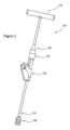
図1を参照すると、股関節全置換術外科処置を受けた患者100の股関節の図が示されている。プロテーゼ構成要素は、患者の骨盤104の調製された寛骨臼に埋め込まれた股臼カップ102を含む。図1に例示されるように、股臼カップ102は、関節形成面を提供するライナ106を含む。また、患者の大腿骨110の近位部の断面図も示されている。プロテーゼの大腿部品は、頸部116を介して大腿骨ステム114に装着された大腿骨頭部112を含む。大腿骨ステム114の遠位端は、セントラライザ118を含む。大腿骨ステム114は、大腿骨の脊髄内空洞内のセメントマントル120内に位置する。脊髄内空洞の遠位端に向かって、セメントリストリクタ122が提供される。図1に例示されるように、大腿骨の遠位の大部分(スタビライザ118)と、好ましくは約10~20mmである側面124のセメントリストリクタ122との間には、隙間が存在する。With reference to FIG. 1, a diagram of the hip joint of a
好ましくは、セメントマントル120は、大腿骨の脊髄内空洞内の略中央に位置するステム114の周りに、数ミリメートル、例えば約2mmの厚さを有する。また、好ましくは、ステムの最遠位部分とセメントリストリクタ124との間の距離は、ステム114をセメント内に沈降させることを可能にするのに十分である。しかしながら、後に再置換術が必要となる場合は、例えば過剰なセメントを除去する際の困難を回避するために、脊髄内空洞内に過剰なセメントが存在することはあまり良いことではない。実際には、距離124は、好ましくは約20mmである。Preferably, the
セメントリストリクタの使用は、当業者によって概ね理解されており、セメントリストリクタは、いくつかのプロテーゼ構成要素が患者の骨の空洞内の適所にセメント固定される他の整形外科処置で使用することができる。簡単に上で考察されたように、好ましくは、セメントリストリクタとプロテーゼインプラント構成要素の遠位大部分との間には、いくらかの有限距離が存在する。しかしながら、プロテーゼ構成要素の端部とセメントリストリクタとの間に好ましい分離124を生じさせ得る空洞内の深さに、セメントリストリクタ122が配置されることを確実にしようとする際に問題が生じる。これは、セメント固定の前に、セメントリストリクタ122が空洞の中へ挿入されるときに視界から隠れるので、視覚的に達成することができるものではない。The use of cement restrictors is generally understood by those skilled in the art, and cement restrictors can be used in other orthopedic procedures in which several prosthetic components are cemented in place within a cavity in a patient's bone. As briefly discussed above, preferably there is some finite distance between the cement restrictor and the distal majority of the prosthetic implant component. However, a problem arises in trying to ensure that the
図2は、第1の実施形態による、及びその遠位端にセメントリストリクタ150が取り付けられた、セメントリストリクタインサータ器具130の側面図を示す。セメントリストリクタインサータ器具130は、近位端のハンドル132と、セメントリストリクタ150をインサータ器具130に着脱可能に取り付けることができる遠位端134(図2では見えない)のアタッチメント形成部と、を有する。シャフト136は、ハンドル132から遠位端134まで延びる。止め具138は、近位端と遠位端との間でシャフト上に提供される。本体140は、シャフト136上に提供される。シャフト136に沿った本体140の位置は、本体140のスペーサ部142に当接する止め具138によって制御される。2 shows a side view of a cement
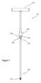
図3は、本体140を取り除いた、器具130全体のうちの一部であるセメントリストリクタインサータ131の側面図を示す。したがって、器具130全体は、本体140及びインサータ131の組立体とみなされ得る。図3に例示されるように、インサータ131は、略Tバーの構造を有する。ハンドル132は、シャフト136の近位端に取り付けられた円筒状クロスバーの形態である。シャフト136は、略円形のロッドの形態を有する。図3に例示されるように、アタッチメント形成部137は、シャフト136の遠位端134に提供され、例示される実施形態では、ねじ山の形態をとり得る。しかしながら、他の実施形態では、アタッチメント形成部は、セメントリストリクタ150の対応する大腿骨特徴部との押し込み嵌めインターフェースを提供し得る。3 shows a side view of the
止め具138は、シャフト136よりも大きい直径に延びる広がり部分を有し、当接する肩部分139を提供する。円筒状ボス152は、遠位端に向かって延び、その中に溝又は凹部154を画定する。Cクリップ又はサークリップ156は、円形溝154内に位置する。サークリップ156は、概して、金属、例えばステンレス鋼などの弾性材料のCリング又は割りリングの形態である。図3に例示されるセメントリストリクタインサータ器具のインサータ部品131は、好適な金属又は合金、例えばステンレス鋼から作製され得る。The
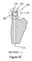
図4A~図4Eは、図2に例示される本体140と略同様の更なる本体160の様々な図を示す。下で更に詳細で説明されるように、図4A~図4Eに示される本体160と図2に示される本体140との間の大きな違いは、インサータ131のシャフト136の軸と平行な方向に沿ったスペーサ要素の長さである。図4Aは、本体160の(概して前後方向の)側面図を示し、図4Bは、側面図を示す。図4Cは、線L-L’に沿って本体を通る断面図を示す。図4Dは、本体160の斜視図を示し、図4Eは、図4Cの断面の一部170の拡大断面図を示す。4A-4E show various views of a
図4Aに最良に例示されるように、本体160は、概して、図1に例示される大腿骨ステム114の近位部と同じ形状を有する。しかしながら、本体160は、ステム114の近位部のみに対応しており、プロテーゼステム114のその遠位部が存在しないという点で、遠位に切頭されている。また、本体160は、プロテーゼステム114の頸部116に対応する部分で切頭される。ステム114の近位部に対応する本体の部分162はまた、ステム114の近位部と実質的に同じ寸法を有し得る。すなわち、本体160は、概して、対応するプロテーゼ構成要素114の近位部と同じ形状及びサイズを有する。4A, the
本体及び対応するプロテーゼの寸法が同一であることは必須ではない。本体は、概ね同じ形態又は形状を有し、機械加工がより容易かつより安価になる、ステムの近位部の簡略化バージョンであり得る。したがって、一般的に言えば、本体は、対応するプロテーゼが経済的に合理的であるような幾何学形状にできる限り近づけなければならない。しかしながら、本体は、大腿骨空洞を形成するために使用される最終ブローチ、又はトライアル、又は切削器具よりも長く、又は広く、又は厚くするべきではなく、さもなければ、尚早に、かつセメントリストリクタが所望の深さまで挿入される前に、本体が大腿骨空洞の内部壁に接触する。It is not essential that the dimensions of the body and the corresponding prosthesis be identical. The body can be a simplified version of the proximal portion of the stem that has roughly the same form or shape and is easier and less expensive to machine. Thus, generally speaking, the body should be as close as possible to the geometry for which the corresponding prosthesis is economically reasonable. However, the body should not be longer, wider, or thicker than the final broach, or trial, or cutting instrument used to form the femoral cavity, or it will contact the interior wall of the femoral cavity prematurely and before the cement restrictor has been inserted to the desired depth.
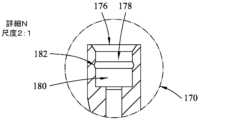
スペーサ部164は、本体166の近位部から、かつインサータ131のシャフト136の長手方向軸と略平行である本体の長手方向軸168に概ね沿って延びる。図4Cに最良に例示されるように、本体162は、長手方向軸に概ね沿って、スペーサ164の下部開口174と上部開口部176との間に延びるチャネル172を画定する。The
スペーサ要素164は、略円筒状の構造を有し、その中に僅かにテーパ付きの空洞178を画定する。図4C及び図4Eに最良に例示されるように、スペーサの内壁180は、長手方向軸の周りに延びる溝182をその中に画定する。本体160とセメントリストリクタインサータ130の残部との間に解放可能なアタッチメント機構を提供するために、空洞178は、その中でボス152をぴったりと受容するようにサイズ決定され、溝182は、その中で回路156を受容するように位置決め及び寸法決めされる。The
したがって、本体160は、スペーサ164が止め具138に当接して、インサータの残部に対する本体の位置を固定するまで、インサータのシャフト136に沿って摺動し得る。解放可能なアタッチメント機構は、本体が取り扱い中にシャフトから意図せず取り外されることを防止する。Thus, the
図4Aに最良に例示されるように、視覚的深さガイド特徴部190は、本体の前面192に提供される。同様の位置合わせ特徴部は、図面では見えない後ろ側に提供される。As best illustrated in FIG. 4A, visual depth guide features 190 are provided on the
例示される実施形態では、視覚的深さガイド特徴部190は、各々が直線セクションを備える複数のマーキング194、196、198の形態である。直線セクションは、対応するステム構成要素114の頸部軸の方向に対して略垂直に構成される。実際に、対応するマーキング119は、図1のプロテーゼステム構成要素114上に見ることができる。In the illustrated embodiment, the visual
上で説明されたように、インサータ器具130の本体部160、140は、シャフト136に沿って摺動させて、止め具138に着脱可能に取り付けることによって、インサータ131に解放可能に取り付け可能である。実際には、各々がプロテーゼ構成要素の異なるサイズに対応する、複数の本体部が提供され得る。例えば、図5は、異なるサイズのプロテーゼ大腿骨ステムに各々が対応する、第1の本体140、第2の本体160、及び第3の本体200を示す。他の実施形態では、より多い又はより少ない数の本体が提供され得ることが理解されるであろう。この説明される実施例では、第1の本体140が最小のステムに対応し、第2の本体160が中間サイズのステムに対応し、第3の本体200が最大のステムに対応する。As described above, the
一般的に言えば、ステムのサイズは、内側外側方向におけるそのサイズによって決定される。ステムの長さはまた、より小さいステムがより大きくサイズ決定されたステムよりも前後方向においてより短い長さを有するように、ステムのサイズによっても変化し得る。したがって、第1の本体140は、上下方向において最も短い長さを有するプロテーゼ大腿骨ステムに対応し、第2の本体160は、上下方向において第1の長さよりも長い長さを有する第2のプロテーゼ大腿骨ステムに対応し、第3の本体200は、上下方向において最も長い長さを有する最大のプロテーゼ大腿骨ステムに対応する。Generally speaking, the size of a stem is determined by its size in the medial-lateral direction. The length of the stem may also vary with the size of the stem, with smaller stems having a shorter length in the anterior-posterior direction than larger sized stems. Thus, the
止め具138と、セメントリストリクタが取り付けられるインサータの遠位端134との間の距離が固定されるので、対応するステムのサイズが増大するにつれて各本体のスペーサ部の長さが減少する。このようにして、セメントリストリクタ150の挿入深さを制御するために使用される視覚的深さガイド特徴部を使用することによって、インサータ130を使用して、プロテーゼインプラントの最遠位点から好ましく分離させて、セメントリストリクタ150を確実に位置決めすることができる。Because the distance between the
第1の本体140は、上下方向に最も短い長さを有するプロテーゼステムに対応し、したがって、止め具138に対してシャフトの更に下に視覚的深さガイド特徴部を位置決めするように、最も長いスペーサ部142を有する。中間にサイズ決定された本体160は、第1の本体140に対応する大腿骨ステムよりも長い上下方向の長さを有する大腿骨ステムに対応し、したがって、視覚的深さガイド特徴部190を止め具138により近づけて位置決めするように、より短いスペーサ164を有する。The
第3の本体200は、上下方向に最も長い長さを有する大腿骨ステムに対応し、したがって、視覚的深さガイド特徴部210を止め具138に最も近づけて位置決めするように、最も短いスペーサ204を有する。The
本体の長手方向軸に沿ってスペーサ部の長さを変化させることによって、本体に対応するステムの上下方向における異なる長さを補償するために、視覚的深さガイド特徴部を使用して、埋め込まれるときに、セメントリストリクタとプロテーゼステムの最遠位部との間で、所望の分離124に対応する空洞内の深さまでのセメントリストリクタ150の挿入を案内し得る。By varying the length of the spacer portion along the longitudinal axis of the body to compensate for the different vertical lengths of the stem relative to the body, the visual depth guide feature may be used to guide insertion of the
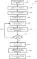
図6を参照すると、セメントリストリクタ150を大腿骨の脊髄内空洞の中の適切な深さに挿入するために、セメントリストリクタインサータ器具130を使用する方法300を例示するフローチャートが示されている。股関節置換処置全体の様々な部品は、明確にするため取り除かれているが、概して当業者に知られている。したがって、図6は、単にインサータ器具130の使用を説明するために有用な股関節全置換術処置の一部だけを例示する。302で、大腿骨が調製される。これは、大腿骨の天然頸部を切除することと、更には大腿骨の近位解剖学的軸に概ね沿って延びる脊髄内空洞を形成することと、を含み得る。脊髄内空洞を形成するために、ブローチ及びラスプなどの様々な切削器具が使用され得る。いくつかの実施形態では、大腿骨の中に空洞を形成するために、最終ブローチとしても機能するトライアル大腿骨ステム構成要素を使用してもよい。With reference to FIG. 6, a flow chart is shown illustrating a
例えば、図7は、患者の大腿骨の近位部110の断面図を示し、天然大腿骨頸部の切除によって生じる切除平面113を示す。トライアル大腿骨ステム400は、頸部402と、ステム上に設置され、大腿骨空洞をブローチ加工するために使用されている切削歯404と、を有するように示されている。トライアルステム400の前方側壁は、本体、例えば本体140上に存在するものと類似する視覚的深さガイド特徴部406と、対応するプロテーゼ大腿骨ステム構成要素114と、を含む。視覚的深さガイド特徴部406は、同様に、ステムの頸部軸に対して略垂直な3つの平行な線の形態である。ラインの各々は、内側外側方向及び上下方向における骨盤に対する大腿骨の異なる量のオフセットに対応する。中間線408は、中間の量の内側外側オフセット及び下上オフセット(脚長とも称される)に対応し得る。上部線410は、低減させた量の上下オフセット及び内側外側オフセットに対応し得る。下部線412は、増加させた量の内側外側オフセット及び上下オフセットに対応し得る。したがって、外科医は、所望の変化に、該当する場合はオフセットに対応するマーキングのうちの1つが大腿骨切除の平面と整列されるまで、トライアルステム400を使用して、大腿骨の脊髄内空洞のブローチ加工を完了し得る。図7に例示されるように、中間のオフセットされたライン408は、大腿骨の切除平面113と概ね整列される。For example, FIG. 7 shows a cross-sectional view of the
大腿骨トライアル400は、対応してサイズ決定されたプロテーゼ大腿骨ステム114を有する。しかしながら、プロテーゼ大腿骨ステム114は、プロテーゼステム114を取り囲むセメントマントル120を提供するために、トライアルステム400よりも僅かに小さいサイズを有する。したがって、304でトライアルが完了すると、外科医は、トライアル大腿骨ステム400に対応するプロテーゼ大腿骨ステムのサイズを決定し得る。The femoral trial 400 has a correspondingly sized prosthetic
図7に更に例示されるように、本体140は、プロテーゼ大腿骨ステム114に対応する形状及びサイズを有する。したがって、306で、外科医は、プロテーゼ大腿骨ステム114の選択されたサイズに対応するインサータの本体を選択し得る。As further illustrated in FIG. 7, the
308で、選択された本体104が、シャフトに沿って摺動させることによってインサータ131に取り付けられ得、解放可能なアタッチメント機構を介して取り付けられ得る。上で考察されたように、インサータの長手方向軸に沿った本体140の位置は、スペーサ部142と止め具138との当接によって決定される。At 308, the selected
次いで、310で、セメントリストリクタトライアルがインサータ器具130の遠位端に取り付けられ得る。次いで、インサータ器具130を使用して、セメントリストリクタトライアルを大腿骨の脊髄内空洞の中へ導入し得る。概して、セメントリストリクタトライアルの目的は、使用されるセメントリストリクタの適切な直径を測定することである。したがって、外科医は、セメントリストリクタの意図した目標位置の近くの脊髄内空洞の直径を測定するために、セメントリストリクタトライアルを脊髄内空洞の中へ遠位に移動させ得る。トライアルの正確な位置決めは重要でないので、これは、単純に感触によって行われ得る。代替的又は追加的に、312で、外科医は、大腿骨の切除平面113に対する、以前に計画した位置に対応するマーキング、例えばマーキング408の位置を比較することによって、本体の前面の視覚的深さガイド特徴部144を使用し得る。At 310, the cement restrictor trial may then be attached to the distal end of the
314で、外科医は、セメントリストリクタトライアルが目標挿入深さに適切な直径を有するかどうかを判断し得る。有しない場合、本方法は、流れ線316によって例示されるように、ステップ310に戻ってもよく、異なるセメントリストリクタトライアルが、より大きい又はより小さい直径の導入器の遠位端に取り付けられ得る。したがって、本方法は、セメントリストリクタの直径が成功裏に決定されるまで繰り返され得る。At 314, the surgeon may determine whether the cement restrictor trial has an appropriate diameter for the target insertion depth. If not, the method may return to step 310, as illustrated by
318で、セメントリストリクタトライアルを取り外した後に、トライアルによって決定された直径を有するセメントリストリクタがロッドの遠位端に解放可能に取り付けられる。ねじ接続が使用される実施形態では、次いで、セメントリストリクタが、インサータ器具130の遠位端134のねじ形成部にねじ込まれる。押し込み嵌めアタッチメント機構が使用される他の実施形態では、次いで、セメントリストリクタ150が、単純にインサータ器具130の遠位端134に押し込まれ得る。次いで、320で、セメントリストリクタ150が脊髄内空洞に導入され、インサータ130を使用して、セメントリストリクタ150を脊髄内空洞の中へ挿入する。本体140の形状は、インサータ130の長手方向軸が、前頭面内で傾斜させるのではなく、空洞の中心軸と概ね整列されることを確実にするのを補助する。しかしながら、本体140の寸法は、トライアルステム400の寸法よりも小さく、したがって、それ自体は、セメントリストリクタの挿入深さを制限しない。むしろ、本体の形状は、セメントリストリクタの正しい挿入深さに関する視覚的状況を外科医に提供するのを補助する。具体的には、本体140上の視覚的深さガイド特徴部は、トライアルステム上の視覚的深さガイド特徴部406、更にはプロテーゼステム上の視覚的深さガイド特徴部119に対応する。At 318, after removing the cement restrictor trial, a cement restrictor having a diameter determined by the trial is releasably attached to the distal end of the rod. In embodiments where a threaded connection is used, the cement restrictor is then threaded into the threaded formation on the
したがって、外科医は、以前にトライアルされたマーキングに対応するマーキング、この実施例では中央の線が大腿骨の切除平面113と整列されるまで、インサータ器具を骨髄内管の中へ進行させ得る。この時点で、外科医は、セメントリストリクタ150が大腿骨の骨髄内管内の目標深さに位置決めされたことを確信することができ、目標深さ位置は、切除平面113と整列されている視覚的深さガイド特徴部119の同じ中間線によって画定される対応する位置において骨髄内管に挿入されたときに、プロテーゼステム114の最遠位部からの適切な程度の分離124を有する。The surgeon may thus advance the inserter instrument into the intramedullary canal until a marking, in this example a central line, corresponding to a previously trialed marking is aligned with the
したがって、押し込み嵌めが使用される実施形態では、大腿骨の内壁とセメントリストリクタの外面との間のより大きい摩擦力が、インサータの遠位端とセメントリストリクタとの間の押し込み嵌めインターフェースの摩擦力に打ち勝ち、よって、インサータ器具130が、単純に、脊髄内空洞から引き出され得、セメントリストリクタ150を目標深さにおいて適所に固定されたままにする。Thus, in embodiments where a push-fit is used, the greater frictional force between the inner wall of the femur and the outer surface of the cement restrictor overcomes the frictional force of the push-fit interface between the distal end of the inserter and the cement restrictor, so that the
代替的に、ねじ螺合アタッチメントが使用される場合、ハンドル132を使用して、本体140に対して回転し得るシャフト136を回転させることができ、それによって、セメントリストリクタ150からインサータの遠位端134を取り外すことを可能にする。サークリップ及び溝の解放可能なアタッチメント機構は、本体に対するシャフト136の回転を可能にし、それによって、ねじ山のアタッチメント機構の係合解除を可能にする。したがって、322で、図1に例示されるように、インサータが、セメントリストリクタから分離され、目標深さにおいて適所に残される。Alternatively, if a threaded attachment is used, the
その結果、セメントが、骨髄内管の中へ、次いで、導入されたプロテーゼステム114の中へ導入され得、大腿骨の切除平面113と整列されたその対応する視覚的深さガイド特徴部の中央マーキングによって位置決めされ得る。As a result, cement can be introduced into the intramedullary canal and then into the introduced
図8A及び図8Bを参照すると、セメントリストリクタインサータ器具の一部として使用され得る本体500の更なる実施形態の側面図及び斜視図が示されている。本体500は、本体がインサータの止め具に解放可能に取り付けられる解放可能なアタッチメント機構以外は、上で説明した第1の実施形態と略同様である。図8A及び図8Bに示される本体500は、図2、図5、及び図7に示される本体140と概ね同じ幾何学形状及びサイズを有する。本体500は、概して、対応する大腿骨ステム114の近位部に対応する形状及びサイズを有する。各々が線を含む複数のマーキングの形態の視覚的深さガイド特徴部502が、本体500の前面504に設けられる。8A and 8B, side and perspective views of a further embodiment of a
同様に、スペーサ506は、本体500の上部から本体の長手方向軸に概ね沿って延び、使用時にインサータ131のシャフト136を受容するための円筒状空洞をその中に画定する。スペーサ506の近位端は、インサータの止め具138に当接するように構成された肩部508を画定する。しかしながら、例示される実施形態では、サークリップ及び溝を使用する代わりに、解放可能なアタッチメント機構510は、4つの弾性舌状部を含むスナップ嵌めコネクタの形態である。インサータ131の止め具138は、略環状の空洞をその中に画定し、更には舌状部の自由端の突起、例えば舌状部514の突起512を受容するように構成された溝をスペーサの内壁に画定する。したがって、本体500は、上で説明した第1の実施形態と略同様に使用することができる。ここでも、アタッチメント機構のスナップ嵌め部品は、インサータのシャフトが本体に対して回転することを可能にし、したがって、この本体を使用して提供されるセメントリストリクタインサータを、押し込み嵌め接続又はねじ嵌め接続を介して取り付けられたセメントリストリクタと共に使用することができる。Similarly, the
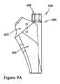
図9A及び図9Bは、本体600の第3の実施形態の側面図及び斜視図を示す。ここでも、本体600は、対応するプロテーゼ大腿骨ステム114の形状及び寸法を有し、その前面604上に視覚的深さガイド特徴部602を含む。例示される実施形態では、視覚的深さガイド特徴部602は、本体600の長手方向軸と平行な軸に沿って等間隔に離間配置された複数の円又は点の形態である。本体600は、本体200に概ね対応し、同様に、本体600の上端部から延びるスペーサ要素606を含む。スペーサ606の近位面608は、インサータの止め具138に当接して、インサータ器具に対する本体の位置を制御するように配設されている。9A and 9B show side and perspective views of a third embodiment of a
しかしながら、図9Bに最良に例示されるように、本体600の解放可能なアタッチメント機構は、本体の前面604及び後面612の一部分によって画定されている略開チャネル610によって提供される。チャネル610は、本体の長手方向軸に概ね沿って延び、止め具138の真下でインサータ131のシャフト136を受容するように寸法決めされる。この本体を使用する場合、インサータ131は、ボス152を省略し、よって、本体600は、単純に、スペーサ606が止め具138の最遠位表面に当接した状態で、インサータのシャフト136の上へクリップ留めされ得る。本体600は、スナップ嵌め式の解放可能なアタッチメント機構を提供するための好適な可塑性材料から作製される。図9Bにも例示されるように、溝614は、チャネル610の内面壁616によって画定され得る。隆起リング(proud ring)は、インサータ131のシャフト136の周りに延び得、表面608が止め具138の遠位面に当接したときに溝614内で受容されるように位置決めされて、止め具138に対する本体600の正しい相対的位置決めを確実にして、本体がシャフト136を遠位に下って不正確な相対位置に摺動されるのを防止し得る。材料のリングは、その後にいくつかの別々の部品をシャフトに取り付けるのではなく、機械加工することによって形成されたシャフトの一体部分であり得る。However, as best illustrated in FIG. 9B, the releasable attachment mechanism of the
セメントリストリクタの使用は、大腿骨ステムに限定されず、実際には、空洞の中へ延びて外科医に不可視である部分のようないくつかのステムを有する他のセメント固定された整形外科用インプラントに使用され得ることが理解されるであろう。対応するプロテーゼインプラントの近位部と同じ形状及び寸法を有する本体の使用は、いくつかの視覚的深さガイド特徴部を使用して患者の骨のいくつかの部分と比較することによって、セメントリストリクタの挿入深さは正しいが、本体及び対応するプロテーゼインプラントの共通の状況の範囲内にあるかどうかを、外科医がより良好に理解すること及び/又は想起するのを補助することを意図する。数多くの実施形態では、本体自体は、挿入の深さを制御するために使用されない。むしろ、本体は、セメント空洞を受容するために空洞の壁とプロテーゼインプラントとの間に必要とされる隙間のために、空洞よりも小さい寸法を有する。本体は、空洞の近位部を部分的に充填することによって、インサータのいくらかの中央化を補助し得る。しかしながら、本体の形状及びサイズは、インプラントがその同じ位置にあるときに本体が正しい位置にあることを直ちに理解することができるように、外科医への視覚的及び状況的なフィードバックを提供することを更に意図する。It will be appreciated that the use of the cement restrictor is not limited to femoral stems, and may in fact be used with other cemented orthopedic implants that have some stem-like portions that extend into the cavity and are not visible to the surgeon. The use of a body having the same shape and dimensions as the proximal portion of the corresponding prosthetic implant is intended to help the surgeon better understand and/or recall whether the insertion depth of the cement restrictor is correct but within the common context of the body and the corresponding prosthetic implant by comparing it to some portion of the patient's bone using some visual depth guide features. In many embodiments, the body itself is not used to control the depth of insertion. Rather, the body has smaller dimensions than the cavity due to the clearance required between the walls of the cavity and the prosthetic implant to receive the cement cavity. The body may aid in some centering of the inserter by partially filling the proximal portion of the cavity. However, the shape and size of the body is further intended to provide visual and contextual feedback to the surgeon so that they can immediately understand that the body is in the correct position when the implant is in that same position.
現在選択されている本体のサイズに関するセメントリストリクタの相対位置は、インサータのシャフトの長手方向軸と略平行な軸に沿ったスペーサ要素の長さ及び本体上の視覚的深さガイド特徴部の位置によるロッド上の本体の正しい位置決めによって対処される。したがって、同じインサータシャフトは、異なるサイズのステム長さを有する異なるサイズのプロテーゼインプラントに対応する複数の異なる本体と共に使用することができる。The relative position of the cement restrictor with respect to the currently selected body size is addressed by the length of the spacer element along an axis generally parallel to the longitudinal axis of the inserter shaft and the correct positioning of the body on the rod by the location of the visual depth guide feature on the body. Thus, the same inserter shaft can be used with multiple different bodies corresponding to different sized prosthetic implants with different sized stem lengths.
したがって、本開示の一態様はまた、インサータ器具と、異なるサイズの複数の本体と、任意選択的に、異なるサイズの複数の対応するプロテーゼインプラントと、を含む、部品又は外科システムのキットにも関する。Thus, one aspect of the present disclosure also relates to a kit of parts or surgical system that includes an inserter instrument, a plurality of bodies of different sizes, and, optionally, a plurality of corresponding prosthetic implants of different sizes.
セメント固定ステムを使用し得る他の共通の整形外科用インプラントとしては、従来型肩部及びリバース型肩部両方の上腕骨ステム、更には膝プロテーゼの脛骨構成要素及び大腿骨構成要素を含む。いくつかの大腿骨構成要素は、特に再置換術で使用される、セメント固定ステムを含む。Other common orthopaedic implants that may use cemented stems include humeral stems in both conventional and reverse shoulders, as well as tibial and femoral components of knee prostheses. Some femoral components, especially those used in revision procedures, include cemented stems.
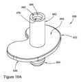
例えば、図10A及び図10Bには、対応するプロテーゼ脛骨構成要素の形状及びサイズを有する本体650が例示されている。プロテーゼ脛骨構成要素は、概して、下面から延び、上側の軸受面のためのアタッチメント機構を提供するステムを有する脛骨トレイの形態を有し得る。したがって、セメント固定ステムを有する脛骨トレイが使用される場合、同じ一般的な手法も使用されてよく、この手法では、本体650が、脛骨プロテーゼの近位部の、すなわち少なくともステムの最遠位部分を含まない形状及び寸法を有する。例えば、図10A及び図10Bに例示されるように、本体650は、対応するプロテーゼ構成要素の脛骨トレイの一般的な形状及びサイズを有する脛骨トレイ部652を含む。脛骨ステム654の少なくとも一部は、脛骨トレイ部652の下側656から下位方向に延びる。一対のウィング又はフランジ658、660は、ステム654とトレイ652の下側656との間に延びる。上で説明された本体と同様に、スペーサ662は、トレイ652の上面664から、概ね上下軸の方向に、かつインサータ131のシャフト136の長手方向軸と平行に延びる。スペーサ662、トレイ部652、及びステム部654は、それらの間に、使用時にインサータ131のシャフト136が挿入される中央円筒状空洞666を画定する。スペーサ662の内面668は、インサータ131のサークリップを受容して、シャフト136が本体650に対して回転することも可能にする解放可能なアタッチメント機構を提供するように配設された溝670を画定する。For example, FIGS. 10A and 10B illustrate a
シャフト136の長手方向軸の方向におけるスペーサ662の長さは、スペーサ662の自由端がインサータ131に装着されて止め具138に当接したときに、セメントリストリクタが、脛骨脊髄内空洞内で、(近位脛骨切断によって生じる)脛骨の切除された表面にトレイ652の下側又は下面656を着座させたときに対応するプロテーゼ構成要素のステムの最遠位部から適切な距離124に位置するように選択される。したがって、この実施形態では、セメントリストリクタの正しい位置決めは、本体のマーキング又は構造部を患者の骨のいくつかの部分と比較するのではなく、脛骨トレイ部652を、切除された脛骨表面と面一に着座させたことを外科医が観察することによって決定される。したがって、この実施形態では、トレイ部652の下側の面又は下面656は、セメントリストリクタの挿入深さが外科医によって視覚的に評価され得る、本体650の視覚的深さガイド特徴部を提供する。The length of the
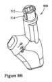
更なる一実施例として、図11は、概して、上腕骨ステム又は肩部ステムプロテーゼの形状及び寸法を有する本体710を含む、セメントリストリクタインサータ器具700の更なる実施形態を示す。肩部ステムプロテーゼは、典型的には、リバース型肩関節形成処置において使用される。肩部ステムプロテーゼは、患者の上腕骨内の脊髄内空洞に挿入されて浅いカップを提供し、このカップには、軸受構成要素が挿入されて、患者の肩部内に位置する対応するボール型プロテーゼインプラントのための関節形成面を提供し得る。したがって、本体710は、概して、ステム712の一部及びカップ状の部分714を含む上腕骨プロテーゼインプラントの形状及び形状を有する。カップ部714は、略環状の壁716と、上腕骨の脊髄内空洞内のセメントリストリクタインサータの正しい位置決めを評価するために使用される視覚的深さガイド特徴部を提供する上縁部又は表面718と、を含む。同様に、スペーサ部720は、本体710の上部から延び、本体710をインサータ131のサークリップに解放可能に取り付けるための溝722が、その中のスペーサ部720の内面724内に画定される。スペーサ720、カップ部714、及びステム部712は、それらの間に、使用時にインサータ131のシャフト136が挿入される中央円筒状空洞726を画定する。As a further example, FIG. 11 illustrates a further embodiment of a cement
シャフト136の長手方向軸の方向におけるスペーサ720の長さは、スペーサ720の自由端がインサータ131に装着されて止め具138に当接したときに、セメントリストリクタが、上腕骨脊髄内空洞内で、壁716の表面718を上腕骨の近位部に形成された空洞の周縁と整列されたときに対応するプロテーゼ構成要素のステムの最遠位部から適切な距離124に位置するように選択される。図11に例示されるセメントリストリクタインサータ器具700の使用は、本体の縁部又は表面718を患者の上腕骨の切除された又は別様に調製された部分と整列されることによってセメントリストリクタ150の正しい挿入深さが決定されること以外は、図2を参照して上で説明されたものと概ね同じである。The length of the
上で説明された本体部は、様々な材料から作製され得、様々なプラスチック、特に重合プラスチックが特に好適である。例えば、本体部は、アセタール又はポリオキシメチレン(Polyoxymethylene、POM)、ポリフェニルスルホン(Polyphenylsulphone、PPS)、ポリエーテルエーテルケトン(Polyetheretherketone、PEEK)、ポリアリールエーテルケトン(Polyaryletherketone、PAEK)、又は類似物、更には、それらのプラスチックの充填バージョン又は類似物から作製され得る。The body portion described above can be made from a variety of materials, with various plastics being particularly suitable, particularly polymeric plastics. For example, the body portion can be made from acetal or polyoxymethylene (POM), polyphenylsulphone (PPS), polyetheretherketone (PEEK), polyaryletherketone (PAEK), or the like, as well as filled versions or the like of these plastics.
したがって、本明細書で説明される様々な器具のセット及びそれによって可能になる方法によって提供される、いくつかの異なる利益が存在することが明らかになるであろう。It will therefore become apparent that there are several distinct benefits provided by the various sets of instruments and methods enabled thereby described herein.
本明細書において、例示的な実施形態が、選択された詳細事項のセットに関して提示されてきた。しかしながら、当業者であれば、これらの選択された詳細事項の異なるセットを含む、多くの他の例示的な実施形態が実践され得ることを理解するであろう。以下の特許請求の範囲は、全ての可能な例示的な実施形態を網羅することが意図される。Exemplary embodiments have been presented herein with respect to a selected set of details. However, one of ordinary skill in the art will appreciate that many other exemplary embodiments may be practiced that include different sets of these selected details. The following claims are intended to cover all possible exemplary embodiments.
上記の図中のフローチャートのステップは、特定の順序が本質的に必要とされるか、又は明示的に述べられていない限り、他の順序で実行され得る。また、当業者であれば、1つの例示的な方法が考察されているが、本明細書における内容は、様々に組み合わされて、他の例も同様にもたらすことができること、及びこの詳細な説明によって提供される文脈内で理解されるべきであることを認識するであろう。The steps of the flowcharts in the above figures may be performed in other orders unless a particular order is inherently required or explicitly stated. Additionally, one skilled in the art will recognize that while one exemplary method is discussed, the contents herein may be combined in various ways to yield other examples as well, and should be understood within the context provided by this detailed description.
本開示は様々な改変及び代替的形態に適しているが、それらの具体的事項が例示のために図面に示され、詳細に説明されてきた。しかしながら、説明された具体的な実施形態以外の他の実施形態もまた可能であることを理解されたい。添付の特許請求の範囲の範囲内に含まれる全ての修正、均等物、及び代替の実施形態もまた想定される。While the present disclosure is susceptible to various modifications and alternative forms, specific details thereof have been shown by way of example in the drawings and have been described in detail. It will be understood, however, that other embodiments are possible other than the specific embodiments described. All modifications, equivalents, and alternative embodiments falling within the scope of the appended claims are also contemplated.
〔実施の態様〕
(1) セメントリストリクタインサータ器具であって、
インサータであって、近位端のハンドルと、セメントリストリクタを解放可能に取り付けるための、遠位端のセメントリストリクタアタッチメント形成部と、前記近位端から前記遠位端まで延びるシャフトと、前記シャフト上の、かつ前記近位端と前記遠位端との間の止め具と、を有する、インサータと、
本体であって、整形外科用プロテーゼインプラントの形状に対応する形状と、スペーサと、可視の深さガイド特徴部と、前記本体を前記ロッドに解放可能に取り付け可能である解放可能なアタッチメント機構と、を有する、本体と、を備え、前記可視の深さガイド特徴部が、前記セメントリストリクタが挿入される患者の骨の特徴部と整列されるときの、目標セメントリストリクタ位置に対応する前記止め具に前記スペーサが当接したときに、前記スペーサが、前記可視の深さガイド特徴部を前記インサータに対して固定位置に位置決めするように構成されている、セメントリストリクタインサータ器具。
(2) 前記解放可能なアタッチメント機構が、押し込み嵌め機構又はスナップ嵌め機構を含む、実施態様1に記載のセメントリストリクタインサータ器具。
(3) 前記止め具が、アタッチメント形成部を含み、前記解放可能なアタッチメント機構が、前記アタッチメント形成部と相互作用する、実施態様1又は2に記載のセメントリストリクタインサータ器具。
(4) 前記アタッチメント形成部が、前記止め具の一部の中にサークリップを含み、前記本体の前記解放可能なアタッチメント機構が、前記サークリップを受容するように構成された溝を含む、実施態様3に記載のセメントリストリクタインサータ器具。
(5) 前記本体が、前記本体の長手方向軸に沿って延び、前記シャフトを受け入れるように構成された開チャネル又は閉チャネルを画定する、実施態様1~4のいずれかに記載のセメントリストリクタインサータ器具。[Embodiment]
(1) A cement restrictor inserter device, comprising:
an inserter having a handle at a proximal end, a cement restrictor attachment formation at a distal end for releasably attaching a cement restrictor, a shaft extending from said proximal end to said distal end, and a stop on said shaft and between said proximal and distal ends;
1. A cement restrictor inserter instrument comprising: a body having a shape corresponding to a shape of an orthopedic prosthetic implant, a spacer, a visible depth guide feature, and a releasable attachment mechanism by which the body can be releasably attached to the rod, wherein the spacer is configured to position the visible depth guide feature in a fixed position relative to the inserter when the spacer abuts the stop that corresponds to a target cement restrictor position when the visible depth guide feature is aligned with a feature of a patient's bone into which the cement restrictor is to be inserted.
2. The cement restrictor inserter instrument of claim 1, wherein the releasable attachment mechanism comprises a push-fit mechanism or a snap-fit mechanism.
3. The cement restrictor inserter instrument of claim 1, wherein the stop includes an attachment forming portion, and the releasable attachment mechanism interacts with the attachment forming portion.
4. The cement restrictor inserter instrument of claim 3, wherein the attachment formation includes a circlip within a portion of the fastener, and the releasable attachment mechanism of the body includes a groove configured to receive the circlip.
5. The cement restrictor inserter instrument of any one of claims 1 to 4, wherein the body defines an open or closed channel extending along a longitudinal axis of the body and configured to receive the shaft.
(6) 前記解放可能なアタッチメント機構が、前記本体に対する前記シャフトの回転を可能にする、実施態様1~5のいずれかに記載のセメントリストリクタインサータ器具。
(7) 前記セメントリストリクタアタッチメント形成部が、押し込み嵌め形成部を含む、実施態様1~6のいずれかに記載のセメントリストリクタインサータ器具。
(8) 前記セメントリストリクタアタッチメント形成部が、ねじ山を含む、実施態様1~6のいずれかに記載のセメントリストリクタインサータ器具。
(9) 前記可視の深さガイド特徴部が、前記本体の一部の表面又は縁部を含む、実施態様1~8のいずれかに記載のセメントリストリクタインサータ器具。
(10) 前記可視の深さガイド特徴部が、前記本体の一部の表面上の1つのマーキングを含む、実施態様1~8のいずれかに記載のセメントリストリクタインサータ器具。(6) The cement restrictor inserter instrument of any one of claims 1 to 5, wherein the releasable attachment mechanism allows for rotation of the shaft relative to the body.
(7) The cement restrictor inserter instrument of any one of claims 1 to 6, wherein the cement restrictor attachment formation comprises a push-fit formation.
8. The cement restrictor inserter instrument of any one of claims 1 to 6, wherein the cement restrictor attachment formation comprises a screw thread.
(9) The cement restrictor inserter instrument of any one of the preceding claims, wherein the visible depth guide feature comprises a surface or edge of a portion of the body.
(10) The cement restrictor inserter instrument of any one of the preceding claims, wherein the visible depth guide feature comprises a marking on a surface of a portion of the body.
(11) 前記可視の深さガイド特徴部が、前記本体の前記一部の前記表面上の複数のマーキングを含み、前記複数のマーキングの各々が、前記患者の前記骨に対する前記整形外科用プロテーゼインプラントの異なる位置に対応する、実施態様10に記載のセメントリストリクタインサータ器具。
(12) 前記整形外科用プロテーゼインプラントが、上腕骨ステム、大腿骨ステム、膝の大腿骨構成要素、又は脛骨構成要素である、実施態様1~11のいずれかに記載のセメントリストリクタインサータ器具。
(13) 前記本体が、前記整形外科用プロテーゼインプラントのサイズに対応するサイズを有する、実施態様1~12のいずれかに記載のセメントリストリクタインサータ器具。
(14) 外科用器具部品のキットであって、
実施態様1~13のいずれかに記載のセメントリストリクタインサータ器具と、
更なる本体であって、前記整形外科用プロテーゼインプラントの前記形状に対応する形状と、更なるスペーサと、更なる可視の深さガイド特徴部と、前記更なる本体を前記シャフトに解放可能に取り付け可能である更なる解放可能なアタッチメント機構と、を有する更なる本体と、を備え、前記更なる本体が、前記本体とは異なるサイズを有し、前記整形外科用プロテーゼインプラントの異なるサイズの前記形状に対応し、前記更なるスペーサが、前記スペーサとは異なるサイズを有し、前記更なる可視の深さガイド特徴部が、前記セメントリストリクタが挿入される前記患者の前記骨の前記特徴部と整列されるときの、前記目標セメントリストリクタ位置に対応する前記止め具に前記更なるスペーサが当接したときに、前記更なる可視の深さガイド特徴部を前記インサータに対して異なる固定位置に位置決めするように構成されている、外科用器具部品のキット。
(15) セメントリストリクタを患者の骨の空洞に挿入する方法であって、
患者の骨の空洞に埋め込まれる整形外科用プロテーゼインプラントの形状に対応する形状を有する本体を選択することであって、前記本体が、可視の深さガイド特徴部を含む、選択することと、
所定の位置において、セメントリストリクタインサータのシャフトに前記本体を解放可能に取り付けることと、
前記セメントリストリクタインサータの前記シャフトの遠位端にセメントリストリクタを取り付けることと、
前記可視の深さガイド特徴部が前記患者の前記骨の特徴部と整列されることによって決定される深さまで、前記本体が上に装着された前記セメントリストリクタインサータを前記空洞の中へ挿入することと、を含む、方法。11. The cement restrictor inserter instrument of claim 10, wherein the visible depth guide feature comprises a plurality of markings on the surface of the portion of the body, each of the plurality of markings corresponding to a different location of the orthopedic prosthetic implant relative to the bone of the patient.
12. The cement restrictor inserter instrument of any one of claims 1 to 11, wherein the orthopaedic prosthetic implant is a humeral stem, a femoral stem, a femoral component of a knee, or a tibial component.
13. The cement restrictor inserter instrument of any one of claims 1 to 12, wherein the body has a size corresponding to a size of the orthopedic prosthetic implant.
(14) A kit of surgical instrument parts, comprising:
A cement restrictor inserter instrument according to any one of claims 1 to 13,
and a further body having a shape corresponding to the shape of the orthopedic prosthetic implant, a further spacer, a further visible depth guide feature, and a further releasable attachment mechanism by which the further body can be releasably attached to the shaft, wherein the further body has a different size than the main body and corresponds to the shape of the different sizes of the orthopedic prosthetic implants, and the further spacer has a different size than the spacer, and the further visible depth guide feature is configured to position the further visible depth guide feature in a different fixed position relative to the inserter when the further spacer abuts the stop that corresponds to the target cement restrictor position when aligned with the feature of the bone of the patient into which the cement restrictor is to be inserted.
(15) A method of inserting a cement restrictor into a bone cavity of a patient, comprising:
selecting a body having a shape corresponding to a shape of an orthopaedic prosthetic implant to be implanted in a patient's bone cavity, the body including a visible depth guide feature;
releasably attaching the body to a shaft of a cement restrictor inserter at a predetermined location;
attaching a cement restrictor to a distal end of the shaft of the cement restrictor inserter;
and inserting the cement restrictor inserter with the body mounted thereon into the cavity to a depth determined by alignment of the visible depth guide feature with a bone feature of the patient.
(16) 前記セメントリストリクタインサータの前記シャフトを前記本体に対して回転させて、前記ロッドの前記遠位端から前記セメントリストリクタを取り外すことと、
前記空洞から前記セメントリストリクタインサータを引き出すことと、を更に含む、実施態様15に記載の方法。
(17) 前記本体を選択することが、前記患者の前記骨の前記空洞に埋め込まれる前記整形外科用インプラントの前記サイズに対応するサイズを有する前記本体を選択することを更に含む、実施態様15又は16に記載の方法。
(18) 前記本体を選択する前に、最終トライアル構成要素、又は最終ブローチ、又は最終リーマ、又は最終切削器具に基づいて、埋め込まれる前記整形外科用インプラントの前記サイズを決定することを更に含む、実施態様17に記載の方法。
(19) セメントリストリクタトライアルを前記シャフトの前記遠位端に取り付けることと、前記本体を取り付けた後に、かつ前記セメントリストリクタを取り付ける前に、前記セメントリストリクタインサータを前記空洞の中へ挿入して、前記セメントリストリクタのサイズをトライアルすることと、を更に含む、実施態様15~18のいずれかに記載の方法。
(20) 前記患者の前記骨の前記特徴部が、前記患者の前記骨の解剖学的特徴部である、実施態様15~19のいずれかに記載の方法。(16) rotating the shaft of the cement restrictor inserter relative to the body to remove the cement restrictor from the distal end of the rod;
16. The method of claim 15, further comprising withdrawing the cement restrictor inserter from the cavity.
17. The method of claim 15 or 16, wherein selecting the body further comprises selecting the body having a size corresponding to the size of the orthopedic implant to be implanted in the cavity of the bone of the patient.
18. The method of claim 17, further comprising determining the size of the orthopedic implant to be implanted based on a final trial component, or a final broach, or a final reamer, or a final cutting instrument prior to selecting the body.
19. The method of any one of claims 15 to 18, further comprising attaching a cement restrictor trial to the distal end of the shaft; and after attaching the body and prior to attaching the cement restrictor, inserting the cement restrictor inserter into the cavity to trial a size of the cement restrictor.
20. The method of any one of claims 15 to 19, wherein the feature of the bone of the patient is an anatomical feature of the bone of the patient.
(21) 前記患者の前記骨の前記特徴部が、前記患者の前記骨の切除された表面、又は縁部、又は周縁である、実施態様15~19のいずれかに記載の方法。
(22) 視覚的深さガイドが、前記本体の表面又は縁部である、実施態様15~21のいずれかに記載の方法。
(23) 視覚的深さガイド特徴部が、前記本体の表面上の1つのマーキングである、実施態様15~21のいずれかに記載の方法。
(24) 前記視覚的深さガイド特徴部が、前記本体の表面上の複数のマーキングを含み、各マーキングが、前記患者の前記骨に対する前記整形外科用プロテーゼインプラントの異なる位置に対応し、前記異なる位置のうちの選択された1つに対応する前記マーキングを使用して、前記セメントリストリクタインサータが挿入される深さを決定することを更に含む、実施態様23に記載の方法。
(25) 前記プロテーゼ整形外科用インプラントが、大腿骨ステムであり、前記患者の前記骨の前記特徴部が、前記大腿骨の頸部切除部である、実施態様15~24のいずれかに記載の方法。21. The method of any one of claims 15 to 19, wherein the feature of the bone of the patient is a resected surface, or an edge, or a rim of the bone of the patient.
22. The method of any one of claims 15 to 21, wherein the visual depth guide is a surface or edge of the body.
23. The method of any one of claims 15 to 21, wherein the visual depth guide feature is a single marking on a surface of the body.
24. The method of claim 23, wherein the visual depth guide feature comprises a plurality of markings on a surface of the body, each marking corresponding to a different position of the orthopedic prosthetic implant relative to the bone of the patient, and further comprising using the marking corresponding to a selected one of the different positions to determine a depth to which the cement restrictor inserter is to be inserted.
25. The method of any one of claims 15 to 24, wherein the prosthetic orthopedic implant is a femoral stem and the feature of the patient's bone is a neck resection of the femur.
(26) 前記プロテーゼ整形外科用インプラントが、脛骨構成要素であり、前記患者の前記骨の前記特徴部が、前記脛骨の近位切除部である、実施態様15~24のいずれかに記載の方法。
(27) 前記プロテーゼ整形外科用インプラントが、上腕骨ステムであり、前記患者の前記骨の前記特徴部は、前記上腕骨の前記近位切除部である、実施態様15~24のいずれかに記載の方法。26. The method of any one of claims 15 to 24, wherein the prosthetic orthopaedic implant is a tibial component and the feature of the patient's bone is a proximal resection of the tibia.
27. The method of claim 15, wherein the prosthetic orthopedic implant is a humeral stem and the feature of the patient's bone is the proximal resection of the humerus.
Claims (14)
Translated fromJapaneseインサータであって、近位端のハンドルと、セメントリストリクタを解放可能に取り付けるための、遠位端のセメントリストリクタアタッチメント形成部と、前記近位端から前記遠位端まで延びるシャフトと、前記シャフト上の、かつ前記近位端と前記遠位端との間の止め具と、を有する、インサータと、
本体であって、整形外科用プロテーゼインプラントの形状に対応する形状と、スペーサと、可視の深さガイド特徴部と、前記本体を前記シャフトに解放可能に取り付け可能である解放可能なアタッチメント機構と、を有する、本体と、を備え、前記可視の深さガイド特徴部が、前記セメントリストリクタが挿入される患者の骨の特徴部と整列されるときの、目標セメントリストリクタ位置に対応する前記止め具に前記スペーサが当接したときに、前記スペーサが、前記可視の深さガイド特徴部を前記インサータに対して固定位置に位置決めするように構成されている、セメントリストリクタインサータ器具。 1. A cement restrictor inserter instrument comprising:
an inserter having a handle at a proximal end, a cement restrictor attachment formation at a distal end for releasably attaching a cement restrictor, a shaft extending from said proximal end to said distal end, and a stop on said shaft and between said proximal and distal ends;
1. A cement restrictor inserter instrument comprising: a body having a shape corresponding to a shape of an orthopedic prosthetic implant, a spacer, a visible depth guide feature, and a releasable attachment mechanism by which the body can be releasably attached tothe shaft , wherein the spacer is configured to position the visible depth guide feature in a fixed position relative to the inserter when the spacer abuts the stop that corresponds to a target cement restrictor position when the visible depth guide feature is aligned with a feature of a patient's bone into which the cement restrictor is to be inserted.
請求項1~13のいずれか一項に記載のセメントリストリクタインサータ器具と、
更なる本体であって、前記整形外科用プロテーゼインプラントの前記形状に対応する形状と、更なるスペーサと、更なる可視の深さガイド特徴部と、前記更なる本体を前記シャフトに解放可能に取り付け可能である更なる解放可能なアタッチメント機構と、を有する更なる本体と、を備え、前記更なる本体が、前記本体とは異なるサイズを有し、前記整形外科用プロテーゼインプラントの異なるサイズの前記形状に対応し、前記更なるスペーサが、前記スペーサとは異なるサイズを有し、前記更なる可視の深さガイド特徴部が、前記セメントリストリクタが挿入される前記患者の前記骨の前記特徴部と整列されるときの、前記目標セメントリストリクタ位置に対応する前記止め具に前記更なるスペーサが当接したときに、前記更なる可視の深さガイド特徴部を前記インサータに対して異なる固定位置に位置決めするように構成されている、外科用器具部品のキット。 1. A kit of surgical instrument parts, comprising:
A cement restrictor inserter instrument according to any one of claims 1 to 13;
and a further body having a shape corresponding to the shape of the orthopedic prosthetic implant, a further spacer, a further visible depth guide feature, and a further releasable attachment mechanism by which the further body can be releasably attached to the shaft, wherein the further body has a different size than the main body and corresponds to the shape of the different sizes of the orthopedic prosthetic implants, and the further spacer has a different size than the spacer, and the further visible depth guide feature is configured to position the further visible depth guide feature in a different fixed position relative to the inserter when the further spacer abuts the stop that corresponds to the target cement restrictor position when aligned with the feature of the bone of the patient into which the cement restrictor is to be inserted.
Applications Claiming Priority (3)
| Application Number | Priority Date | Filing Date | Title |
|---|---|---|---|
| GBGB1919271.5AGB201919271D0 (en) | 2019-12-24 | 2019-12-24 | Surgical instruments and methods |
| GB1919271.5 | 2019-12-24 | ||
| PCT/EP2020/087877WO2021130372A1 (en) | 2019-12-24 | 2020-12-24 | Surgical instruments and methods |
Publications (2)
| Publication Number | Publication Date |
|---|---|
| JP2023508081A JP2023508081A (en) | 2023-02-28 |
| JP7638997B2true JP7638997B2 (en) | 2025-03-04 |
Family
ID=69322667
Family Applications (1)
| Application Number | Title | Priority Date | Filing Date |
|---|---|---|---|
| JP2022538965AActiveJP7638997B2 (en) | 2019-12-24 | 2020-12-24 | Surgical instruments and methods |
Country Status (9)
| Country | Link |
|---|---|
| US (1) | US20230056410A1 (en) |
| EP (1) | EP4081143B1 (en) |
| JP (1) | JP7638997B2 (en) |
| CN (1) | CN114867424B (en) |
| AU (1) | AU2020412322A1 (en) |
| BR (1) | BR112022011884A2 (en) |
| CA (1) | CA3161169A1 (en) |
| GB (1) | GB201919271D0 (en) |
| WO (1) | WO2021130372A1 (en) |
Families Citing this family (2)
| Publication number | Priority date | Publication date | Assignee | Title |
|---|---|---|---|---|
| USD990680S1 (en)* | 2021-06-24 | 2023-06-27 | MAP Medical Solutions, LLC | Flexible rounded surgical osteotome blade |
| US20240197463A1 (en)* | 2022-12-16 | 2024-06-20 | Depuy Ireland Unlimited Company | Orthopaedic surgical system and method for installing cement restrictor components in a direct anterior approach hip replacement surgical procedure |
Family Cites Families (10)
| Publication number | Priority date | Publication date | Assignee | Title |
|---|---|---|---|---|
| US5078746A (en)* | 1989-01-25 | 1992-01-07 | Richards Medical Company | Femoral stem distal centralizer |
| US5383932A (en)* | 1993-04-27 | 1995-01-24 | Johnson & Johnson Professional, Inc. | Absorbable medullary plug |
| DE19621269A1 (en)* | 1996-05-25 | 1997-11-27 | Gmt Medizinische Technik Gmbh | Saddle prosthesis |
| US5972034A (en)* | 1997-07-29 | 1999-10-26 | Joint Enterprises, L.C. A Limited Corporation | Self-venting intramedullary cement restrictor |
| CA2400011A1 (en)* | 2000-03-02 | 2001-09-07 | Knute Buehler | Shrouds for implants |
| GB0028445D0 (en)* | 2000-11-22 | 2001-01-10 | Depuy Int Ltd | A tamp assembly |
| AU2003206468A1 (en)* | 2002-02-08 | 2003-09-02 | Auckland Uniservices Limited | Equipment for use in joint replacement surgery |
| WO2012151589A1 (en)* | 2011-05-05 | 2012-11-08 | Wright Medical Technology, Inc. | Orthopedic surgical guide |
| US9216089B2 (en)* | 2013-03-13 | 2015-12-22 | Depuy (Ireland) | Method of surgically preparing a patient's tibia |
| US11039939B2 (en)* | 2016-02-29 | 2021-06-22 | Smith & Nephew, Inc. | Orthopedic trial apparatus |
- 2019
- 2019-12-24GBGBGB1919271.5Apatent/GB201919271D0/ennot_activeCeased
- 2020
- 2020-12-24CACA3161169Apatent/CA3161169A1/enactivePending
- 2020-12-24USUS17/785,659patent/US20230056410A1/enactivePending
- 2020-12-24JPJP2022538965Apatent/JP7638997B2/enactiveActive
- 2020-12-24BRBR112022011884Apatent/BR112022011884A2/enunknown
- 2020-12-24CNCN202080090018.9Apatent/CN114867424B/enactiveActive
- 2020-12-24WOPCT/EP2020/087877patent/WO2021130372A1/ennot_activeCeased
- 2020-12-24AUAU2020412322Apatent/AU2020412322A1/enactivePending
- 2020-12-24EPEP20841942.4Apatent/EP4081143B1/enactiveActive
Also Published As
| Publication number | Publication date |
|---|---|
| GB201919271D0 (en) | 2020-02-05 |
| JP2023508081A (en) | 2023-02-28 |
| WO2021130372A1 (en) | 2021-07-01 |
| CN114867424A (en) | 2022-08-05 |
| CN114867424B (en) | 2025-07-11 |
| EP4081143B1 (en) | 2024-10-09 |
| CA3161169A1 (en) | 2021-07-01 |
| US20230056410A1 (en) | 2023-02-23 |
| BR112022011884A2 (en) | 2022-09-06 |
| AU2020412322A1 (en) | 2022-08-18 |
| EP4081143A1 (en) | 2022-11-02 |
Similar Documents
| Publication | Publication Date | Title |
|---|---|---|
| US12262899B2 (en) | Systems and methods for preparing bone voids to receive a prosthesis | |
| US12274455B2 (en) | Void filling joint prosthesis and associated instruments | |
| EP2241293B1 (en) | Sleeve for proximal reamer | |
| US11006968B2 (en) | Method and orthopaedic surgical instrument system for surgically preparing a patient's bone | |
| JP7638997B2 (en) | Surgical instruments and methods | |
| JP6391948B2 (en) | Instrument assembly for implanting a stem component of a knee prosthesis and orthopedic procedure for using the same | |
| EP1905364A1 (en) | A kit for removing calcar bone |
Legal Events
| Date | Code | Title | Description |
|---|---|---|---|
| A621 | Written request for application examination | Free format text:JAPANESE INTERMEDIATE CODE: A621 Effective date:20231222 | |
| A131 | Notification of reasons for refusal | Free format text:JAPANESE INTERMEDIATE CODE: A131 Effective date:20240716 | |
| A521 | Request for written amendment filed | Free format text:JAPANESE INTERMEDIATE CODE: A523 Effective date:20241011 | |
| TRDD | Decision of grant or rejection written | ||
| A01 | Written decision to grant a patent or to grant a registration (utility model) | Free format text:JAPANESE INTERMEDIATE CODE: A01 Effective date:20250121 | |
| A61 | First payment of annual fees (during grant procedure) | Free format text:JAPANESE INTERMEDIATE CODE: A61 Effective date:20250219 | |
| R150 | Certificate of patent or registration of utility model | Ref document number:7638997 Country of ref document:JP Free format text:JAPANESE INTERMEDIATE CODE: R150 |