JP7638848B2 - Walls and precast blocks - Google Patents
Walls and precast blocksDownload PDFInfo
- Publication number
- JP7638848B2 JP7638848B2JP2021172388AJP2021172388AJP7638848B2JP 7638848 B2JP7638848 B2JP 7638848B2JP 2021172388 AJP2021172388 AJP 2021172388AJP 2021172388 AJP2021172388 AJP 2021172388AJP 7638848 B2JP7638848 B2JP 7638848B2
- Authority
- JP
- Japan
- Prior art keywords
- blocks
- wall
- precast
- back surface
- formwork
- Prior art date
- Legal status (The legal status is an assumption and is not a legal conclusion. Google has not performed a legal analysis and makes no representation as to the accuracy of the status listed.)
- Active
Links
Images


Landscapes
- Sewage (AREA)
Description
Translated fromJapanese本発明は、タンクなどの壁体とその構築に用いるプレキャストブロック等に関する。The present invention relates to walls of tanks and the like and precast blocks used in their construction.
地上式タンクは筒状の壁体を有するが、この壁体を、プレキャストブロックを壁体の周方向および鉛直方向に並べて構築することがある(例えば、特許文献1参照)。特許文献1では、隣接するプレキャストブロックの間にコンクリートを打設して目地とし、これによりプレキャストブロック同士の接続を行う。Above-ground tanks have cylindrical walls, which are sometimes constructed by lining up precast blocks in the circumferential and vertical directions of the wall (see, for example, Patent Document 1). In
特許文献1では壁体の内面が円周状であり、前記のコンクリートは、プレキャストブロックの背面から延びる鋼板を型枠として打設を行う。しかしながら、この構成では、壁体の内面の平滑性を高めることが比較的難しく、品質確保の容易さの面で課題があった。In
本発明は上記の問題に鑑みてなされたものであり、内面の平滑性を容易に高めることのできる壁体等を提供することを目的とする。The present invention was made in consideration of the above problems, and aims to provide a wall body etc. that can easily improve the smoothness of the inner surface.
前述した課題を解決するための第1の発明は、プレキャストブロックを左右に並べて構築された筒状の壁体であって、平面の内側が正多角形状であり、当該正多角形の辺の中央部で、左右のプレキャストブロックの間の目地が形成され、前記プレキャストブロックの背面が、平面視で前面側に凸となるように折れ曲がった直線状に形成され、左右の前記プレキャストブロックの間の目地の形成に用いる埋設型枠部が、前記埋設型枠部の背面が前記プレキャストブロックの背面の直線部分と同一面となるように配置されたことを特徴とする壁体である。The first invention for solving the above-mentioned problem is a cylindrical wall constructed by lining up precast blocks side by side, the inside of the plane being a regular polygon, the joints between the left and right precast blocks being formed at the center of the sides of the regular polygon, the back surface of the precast block being formed in a straight line that is bent so as to be convex toward the front surface in a plan view, and the embedded formwork section used to form the joints between the left and right precast blocks being positioned so that the back surface of the embedded formwork section is flush with the straight line portion of the back surface of the precast block.
本発明により、壁体の内面を正多角形とし、プレキャストブロックの背面と目地形成用の埋設型枠部を同一面に収めることで、壁体の内面の平滑性を容易に高めることができる。また壁体の内面を正多角形とすることで、上記の埋設型枠部が断面欠損となることを考慮した合理的形状を実現できる。According to the present invention, the smoothness of the inner surface of the wall can be easily improved by making the inner surface of the wall a regular polygon and fitting the back surface of the precast block and the embedded formwork section for forming the joints in the same plane. Also, by making the inner surface of the wall a regular polygon, a rational shape can be realized that takes into account the cross-sectional loss of the embedded formwork section.
前記背面の左右の少なくともいずれかの端部に、鉛直方向に延びる切欠きが設けられ、当該切欠きに端部が収まるように、前記埋設型枠部が配置されることが望ましい。また前記背面の左右の端部に前記切欠きが設けられ、前記切欠きに左右の端部が収まるように、前記埋設型枠部が配置されることも望ましい。
これにより、プレキャストブロックの背面の切欠きに目地形成用の埋設型枠部を収めて壁体の内面を平滑とできる。また背面の左右の端部に切欠きを設けることで、埋設型枠部をプレキャストブロックとは別部材とし、プレキャストブロックの設置後に埋設型枠部のセットを行うことができる。 It is preferable that a notch extending in the vertical direction is provided at least on either the left or right end of the back surface, and that the embedded form part is arranged so that the end fits into the notch. It is also preferable that the notch is provided at the left and right end of the back surface, and that the embedded form part is arranged so that the left and right end fits into the notch.
This allows the embedded formwork for forming joints to be placed in the notches on the back of the precast blocks, making the inner surface of the wall smooth. Also, by providing notches on the left and right ends of the back, the embedded formwork can be made a separate member from the precast blocks, and the embedded formwork can be set after the precast blocks are installed.
前記壁体は、前記プレキャストブロックを左右に並べるとともに上下に積層して構築され、上下の前記プレキャストブロックの間に目地が形成され、前記プレキャストブロックの背面の上下の少なくともいずれかの端部に、左右方向に延びる切欠きが設けられ、当該切欠きに端部が収まるように、上下の前記プレキャストブロックの間の目地の形成に用いる埋設型枠部が配置されることが望ましい。
これにより、上下のプレキャストブロックの接続部についても、左右のプレキャストブロックと同様のディテールを採用することができる。 The wall is constructed by lining up the precast blocks side by side and stacking them vertically, with joints formed between the upper and lower precast blocks, and it is desirable that a notch extending in the left-right direction is provided at at least one of the upper and lower ends of the back surface of the precast block, and that an embedded formwork section used to form the joints between the upper and lower precast blocks is positioned so that the end fits into the notch.
This allows the connection between the upper and lower precast blocks to use the same details as the left and right precast blocks.
前記壁体は、例えば地上式タンクの壁体である。
本発明では、壁体の内面が直線状とされるので、貯留物の貯留に必要な内装設備の取付けが容易になる。 The wall may be, for example, the wall of an above-ground tank.
In the present invention, since the inner surface of the wall is linear, it is easy to install the interior equipment required for storing the stored material.
第2の発明は、左右に並べて筒状の壁体を構築するために用いられるプレキャストブロックであって、背面が、平面視で前面側に凸となるように折れ曲がった直線状に形成され、前記背面の左右の少なくともいずれかの端部に、左右の前記プレキャストブロックの間の目地の形成に用いる埋設型枠部の端部を収めるための、鉛直方向に延びる切欠き、または、その背面が前記プレキャストブロックの背面の直線部分と同一面となるように配置された、前記埋設型枠部が設けられたことを特徴とするプレキャストブロックである。The second invention is a precast block used to construct a cylindrical wall by arranging them side by side, characterized in that the back surface is formed in a straight line that is bent so as to be convex toward the front surface in a plan view, and at least one of the left and right ends of the back surface is provided with a notch extending in the vertical direction to accommodate the end of an embedded formwork part used to form a joint between the left and right precast blocks, or the embedded formwork part is arranged so that its back surface is flush with the straight portion of the back surface of the precast block.
本発明により、内面の平滑性を容易に高めることのできる壁体等を提供できる。The present invention provides a wall body etc. that can easily improve the smoothness of the inner surface.
以下、図面に基づいて本発明の好適な実施形態について詳細に説明する。The following describes in detail a preferred embodiment of the present invention with reference to the drawings.
(1.地上式タンク1)
図1は、本発明の実施形態に係る壁体2を有する地上式タンク1(以下「タンク」ということがある)を示す図である。タンク1は、地盤上の底版5に筒状の壁体2を設けたものであり、壁体2の頂部には金属製の屋根3が設けられる。タンク1は、壁体2の内側で貯留物の貯留を行う。貯留物は特に限定されない。また屋根3はコンクリート製でもよい。(1. Above-ground tank 1)
Fig. 1 is a diagram showing an above-ground tank 1 (hereinafter sometimes referred to as "tank") having a
このタンク1では、壁体2がプレキャストブロック10(以下「ブロック」ということがある)により形成される。ブロック10は、壁体2の周方向に並べるとともに鉛直方向に積層される。壁体2の周方向および鉛直方向に隣り合う上下左右のブロック10の間には、コンクリート等の充填材が設けられ、これにより壁体2の鉛直方向および周方向の目地7が形成される。In this
図2は壁体2の水平方向の断面を示す図である。壁体2の平面の外側は円周状であり、平面の内側は正多角形状(図の例では正三十六角形状)である。壁体2は、当該正多角形の各辺の中央部に当たる位置でブロック10に分割され、隣り合うブロック10の間に目地7が形成される。Figure 2 shows a horizontal cross section of
(2.プレキャストブロック10)
図3は、ブロック10の平面、前面、背面、および側面を示す図である。ブロック10は、ブロック本体(以下「本体」という)11に、鉄筋12、14や穴13等を設けたものである。なおブロック10の前面は壁体2の外面に対応し、ブロック10の背面は壁体2の内面に対応する。図3のブロック10の平面は、前面を下、背面を上として示したものであり、ブロック10の側面は、前面を左、背面を右として示したものである。(2. Precast Block 10)
Fig. 3 is a diagram showing the plan, front, back, and side of the
本体11は矩形板状のコンクリート部材であり、本体11の前面は、平面視において、壁体2の径に応じた円弧状となっている。一方、本体11の背面は、平面視において、前面側に凸となるように折れ曲がった直線状であり、その両端部に切欠き111が設けられる。切欠き111は、鉛直方向に延びるように本体11の全高さに亘って設けられる。The
本体11の背面については、その上端部と下端部にも切欠き112が設けられる。切欠き112は、左右方向に延びるように本体11の全幅に亘って設けられる。なお左右方向は壁体2の周方向に対応し、本体11の幅は、本体11の左右方向の長さを指す。
鉄筋12は、本体11の左右の側面に設けられる。鉄筋12は、左右に隣り合うブロック10の間で機械式継手や重ね継手などの継手を形成するための継手材である。The
穴13は本体11の上面の所定位置に設けられる。鉄筋14は、本体11の下面に、本体11から下方に突出するように設けられる棒材である。穴13と鉄筋14は、平面において対応する位置に設けられる。The
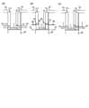
図4は、隣り合うブロック10の接続部を示す図である。図4(a)は、左右のブロック10の接続部について、前面を下、背面を上として水平方向の断面を示したものであり、図4(b)は、上下のブロック10の接続部について、前面を左、背面を右として鉛直方向の断面を示したものである。また図4(c)は上下左右のブロック10の接続部の背面を示す図である。Figure 4 shows the connection between
本実施形態では、図4(a)に示すように、左右のブロック10の前記した切欠き111が左右に隣り合って配置され、これらの切欠き111に左右の端部が収まるように、埋設型枠20が設けられる。ブロック10の背面の前記した直線部分と埋設型枠20の背面は同一面となり、平滑化される。In this embodiment, as shown in FIG. 4(a), the
また図4(b)に示すように、上下のブロック10についても、各ブロック10の前記した切欠き112が上下に隣り合って配置され、これらの切欠き112に上下の端部が収まるように、埋設型枠30が設けられる。ブロック10の背面と埋設型枠30の背面は同一面となり、平滑とされる。As shown in FIG. 4(b), the
埋設型枠20、30は、隣り合うブロック10の間で充填材を充填して目地7を形成するために用いる型枠部(埋設型枠部)である。埋設型枠20、30は、繊維補強モルタル等のセメント系固化材により形成された矩形板状の部材であり、図示しないボルト等の固定具によりブロック10に固定される。ただし埋設型枠20、30の材料や固定方法は特に限定されない。例えば、場合によっては埋設型枠20、30としてゴム板や合板を用いることも可能である。The embedded
なお、図4(c)の埋設型枠20、30の上下の接続に関しては、例えば図5(a)に示すように、埋設型枠20から下方に突出する棒材21を埋設型枠30の孔(不図示)に挿入して埋設型枠20、30を接続でき、棒材21の先端に拡径部22を設けて当該拡径部22が孔内で定着されるようにしてもよい。Regarding the connection between the upper and lower embedded
図5(a)は埋設型枠20を下方の埋設型枠30に接続する場合の例であるが、埋設型枠30を下方の埋設型枠20に接続する場合も、上記と同様、埋設型枠30から下方に突出する棒材を埋設型枠20の孔に挿入することができる。しかしながら、埋設型枠20、30の接続方法がこれに限ることはない。Figure 5 (a) shows an example of connecting an embedded
図4(c)の左右の埋設型枠30の接続については、例えば図5(b)に埋設型枠30の厚さ方向の断面で示すように、左右の埋設型枠30の端部同士を、ボルト等の締結具32を用いて締結することが可能である。締結具32は、埋設型枠30の背面側(図5(b)の上側に対応する)に設けた欠込み31に配置できる。埋設型枠30が薄く、欠込み31を設ける余裕がない場合には、両埋設型枠30に跨るようにその背面に配置した連結板(不図示)を、それぞれの埋設型枠30に締結具等で締結してもよい。ただし、埋設型枠30同士の接続方法がこれらに限ることはない。As for the connection of the left and right buried
また本実施形態では図4(c)に示すように左右の埋設型枠30が当接するように配置されるが、埋設型枠20、30の配置もこれに限らず、例えば図6(a)に示すように上下の埋設型枠20同士が当接するようにしてもよいし、図6(b)に示すように、その当接位置が、埋設型枠30よりも上方であってもよく、図6(c)に示すように埋設型枠30の下端近傍であってもよい。また図6(d)に示すように、埋設型枠20、30の端部を凸形状とし、上下左右の埋設型枠20、30の先端を一点に配置するようにしてもよい。また左右の埋設型枠30を当接させる場合も、図6(e)に示すように、左右の埋設型枠30の端部を台形状に凸とし、台形の頂辺に当たる辺同士で当接するようにしてもよい。In this embodiment, the left and right buried forms 30 are arranged to abut as shown in FIG. 4(c), but the arrangement of the buried forms 20, 30 is not limited to this. For example, the upper and lower buried
(3.壁体2の構築方法)
次に、ブロック10を用いた壁体2の構築方法について説明する。本実施形態では、底版5等を構築した後、1段目(最下段)のブロック10を壁体2の周方向に並べて配置し、その後、2段目のブロック10を、1段目のブロック10の上で壁体2の周方向に並べて配置する。(3. Construction method of wall 2)
Next, a method for constructing the
図7(a)に示すように、2段目のブロック10を配置する際は、下段(1段目)のブロック10の上から上段(2段目)のブロック10を鉛直下方に吊り降ろす。そして、上段のブロック10の鉄筋14を下段のブロック10の穴13に挿入し、上段のブロック10を下段のブロック10の上に配置する。As shown in FIG. 7(a), when placing the second tier of
こうして図7(b)に示すように2段目のブロック10を壁体2の周方向に並べ、左右に隣り合うブロック10の間で両ブロック10の鉄筋12同士の継手を形成し、上下左右のブロック10の間に充填材を充填して目地7とすることで、2段目のブロック10の設置が行われる。目地7の形成時は、図4で説明したように左右のブロック10の間に埋設型枠20を配置し、上下のブロック10の間に埋設型枠30を配置した後、これらのブロック10の間に充填材を充填する。なお充填材の充填時、ブロック10の前面側では在来型枠(不図示)を配置し、当該型枠は充填材の充填後に取り外す。As shown in FIG. 7(b), the second row of
なお1段目のブロック10についても、ブロック10の下面の鉄筋14を底版5の所定位置に形成された穴(不図示)に挿入し、上記と同様の手順で設置することができる。The first-
以上の工程を繰り返し、下段のブロック10の上に上段のブロック10を積み重ねてゆくことで、タンク1の壁体2が構築される。その後、屋根3等の必要な部材の設置を行うことで、タンク1が構築される。By repeating the above process and stacking the
以上説明したように、本実施形態によれば、壁体2の内面を正多角形とし、ブロック10の背面と目地形成用の埋設型枠20を同一面に収めることで、壁体2の内面の平滑性を容易に高めることができる。As described above, according to this embodiment, the inner surface of the
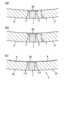
また仮に壁体の内面を円周状とし、壁体に求められる厚さを図8(a)の符号Tで示すとすると、ブロックPの切欠きCの位置で断面欠損となる。一方、この断面欠損を見越して、図8(b)に示すように、壁体の厚さを、必要な厚さTから切欠きCの深さ分だけ増やすと、壁体の一般部(ブロックP同士の接続部を除く部分)で材料の無駄が生じる。If the inner surface of the wall is circular and the required thickness of the wall is shown by the symbol T in Figure 8(a), then there will be a cross-sectional loss at the position of the notch C in the block P. On the other hand, if the thickness of the wall is increased from the required thickness T by the depth of the notch C in anticipation of this cross-sectional loss, as shown in Figure 8(b), material will be wasted in the general part of the wall (excluding the connection between the blocks P).
そこで本実施形態では、壁体2の内面を正多角形状とすることで、図8(b)の壁体に対し、図8(c)の符号Aで示す部分を削減でき、上記の無駄を最小限とできる。このように壁体2の増厚部分を必要最低限にとどめることで、壁体2を、切欠き111(埋設型枠20)が断面欠損となることを考慮した合理的形状とできる。また壁体2の内面が直線状になることで、貯留物の貯留に必要なライナー等の内装設備の取付けも容易になる。Therefore, in this embodiment, by making the inner surface of the wall 2 a regular polygonal shape, the portion indicated by the symbol A in FIG. 8(c) can be eliminated compared to the wall in FIG. 8(b), minimizing the above-mentioned waste. By keeping the increased thickness of the
また本実施形態では、上下のブロック10の接続部についても、切欠き112により左右のブロック10と同様のディテールを採用することができる。In addition, in this embodiment, the connection between the upper and
しかしながら、本発明はこれに限ることはない。例えば本実施形態の壁体2は、地上式タンク1に適用するものに限らず、筒状の構造物全般に適用可能である。また壁体2の平面の外側は円周状であるが、内側と同様正多角形状でもよい。However, the present invention is not limited to this. For example, the
また本実施形態では上下のブロック10間に埋設型枠30を配置しているが、埋設型枠30の代わりに在来型枠を用いることもできる。この場合、図9(a)に背面側を示す上下のブロック10の間で、図9(b)に示すように、端部51が切欠き111の平面形状に応じて折れ曲がった型枠(在来型枠)50をブロック10の背面に配置する。またブロック10の側面に型枠40を、ブロック10の前面に型枠(不図示)を配置する。そして、上下のブロック10間に充填材を充填して図9(c)に示すように目地7を形成し、上記の各型枠を取り外す。その後、左右のブロック10間に前記したように埋設型枠20を配置して充填材を充填し、左右のブロック10間の目地7を形成すればよい。この場合、鉛直断面における断面欠損が無くなるという利点がある。なお、型枠50に関しては、端部51のみ先に取り外し、残りはその後の都合の良い時に取り外すこととしてもよい。In this embodiment, the buried
また本実施形態では、埋設型枠20をブロック10とは別部材とし、ブロック10の設置後に、埋設型枠20の左右の端部が左右のブロック10の切欠き111に収まるように埋設型枠20を配置した。しかしながら、図10(a)に示すように、ブロック10aの背面の左右の端部の一方のみに切欠き111を設け、他方には、目地形成時の埋設型枠として機能する型枠部113(埋設型枠部)をブロック10aの本体11と一体に設けてもよい。In this embodiment, the embedded
型枠部113はブロック10aの本体11から突出するように設けられる板状の部材である。その背面はブロック10aの背面の直線部分と同一面となり、図10(b)に示すように左右のブロック10aのうち一方のブロック10aの型枠部113の端部を他方のブロック10aの切欠き111内に収めるように配置することができる。The
また図10(a)の型枠部113は、ブロック10aの背面の左右両側に設けてもよく、その場合は当該ブロック10aの左右に第1の実施形態のブロック10を配置して、これらのブロック10の切欠き111内に両埋設型枠部113の端部を配置すればよい。あるいは、左右に隣り合う当該ブロック10aの型枠部113同士を当接させてもよい。The
上下のブロック10に関しても、図11(a)に示すように、ブロック10bの背面の上下の端部の一方(図の例では下側)に切欠き112を設け、他方(図の例では上側)には、目地形成時の埋設型枠として機能する型枠部114(埋設型枠部)をブロック10bの本体11と一体に設けてもよい。前記と同様、型枠部114はブロック10bの本体11から突出する板状の部材であり、図11(b)に示すように、一方のブロック10bの型枠部114の端部を他方のブロック10bの切欠き112内に収めるように配置することができる。As for the upper and
なお、上記の埋設型枠部113、114はブロック10a、10bの本体11と一体に形成されるが、埋設型枠部113、114をブロック10a、10bの本体11と別に製造した後、本体11に固定し、その後、ブロック10a、10bの設置を行ってもよい。The above-mentioned embedded
以上、添付図面を参照して、本発明の好適な実施形態について説明したが、本発明は係る例に限定されない。当業者であれば、本願で開示した技術的思想の範疇内において、各種の変更例または修正例に想到し得ることは明らかであり、それらについても当然に本発明の技術的範囲に属するものと了解される。The above describes preferred embodiments of the present invention with reference to the attached drawings, but the present invention is not limited to these examples. It is clear that a person skilled in the art can come up with various modified or revised examples within the scope of the technical ideas disclosed in this application, and it is understood that these also naturally fall within the technical scope of the present invention.
1:地上式タンク
2:壁体
3:屋根
5:底版
7:目地
10、10a、10b:プレキャストブロック
11:本体
12、14:鉄筋
13:穴
20、30:埋設型枠
111、112:切欠き
113、114:型枠部1: above-ground tank 2: wall 3: roof 5: bottom slab 7:
Claims (6)
Translated fromJapanese平面の内側が正多角形状であり、当該正多角形の辺の中央部で、左右のプレキャストブロックの間の目地が形成され、
前記プレキャストブロックの背面が、平面視で前面側に凸となるように折れ曲がった直線状に形成され、左右の前記プレキャストブロックの間の目地の形成に用いる埋設型枠部が、前記埋設型枠部の背面が前記プレキャストブロックの背面の直線部分と同一面となるように配置されたことを特徴とする壁体。 A cylindrical wall constructed by arranging precast blocks side by side.
The inside of the plane is a regular polygon, and the joints between the left and right precast blocks are formed at the center of the sides of the regular polygon.
A wall characterized in that the back surface of the precast block is formed in a straight line that is bent so that it is convex toward the front surface when viewed in a plane, and an embedded formwork section used to form joints between the left and right precast blocks is positioned so that the back surface of the embedded formwork section is on the same plane as the straight portion of the back surface of the precast block.
当該切欠きに端部が収まるように、前記埋設型枠部が配置されたことを特徴とする請求項1記載の壁体。 A notch extending in a vertical direction is provided at least on either the left or right end of the back surface,
2. The wall structure according to claim 1, wherein the embedded formwork portion is arranged so that an end portion fits into the notch.
上下の前記プレキャストブロックの間に目地が形成され、
前記プレキャストブロックの背面の上下の少なくともいずれかの端部に、左右方向に延びる切欠きが設けられ、
当該切欠きに端部が収まるように、上下の前記プレキャストブロックの間の目地の形成に用いる埋設型枠部が配置されたことを特徴とする請求項1から請求項3のいずれかに記載の壁体。 The wall body is constructed by arranging the precast blocks side by side and stacking them vertically,
A joint is formed between the upper and lower precast blocks,
A notch extending in the left-right direction is provided at least at either the upper or lower end of the back surface of the precast block,
A wall structure as described in any one of claims 1 to 3, characterized in that an embedded formwork portion used to form a joint between the upper and lower precast blocks is arranged so that its end portion fits into the notch.
背面が、平面視で前面側に凸となるように折れ曲がった直線状に形成され、前記背面の左右の少なくともいずれかの端部に、
左右の前記プレキャストブロックの間の目地の形成に用いる埋設型枠部の端部を収めるための、鉛直方向に延びる切欠き、
または、
その背面が前記プレキャストブロックの背面の直線部分と同一面となるように配置された、前記埋設型枠部
が設けられたことを特徴とするプレキャストブロック。 A precast block used to construct a cylindrical wall by arranging it side by side,
The rear surface is formed in a straight line bent so as to be convex toward the front surface in a plan view, and at least one of the left and right ends of the rear surface is
A vertically extending notch for accommodating the end of an embedded formwork portion used to form a joint between the left and right precast blocks;
or
A precast block comprising: an embedded formwork portion disposed so that its back surface is flush with the straight portion of the back surface of the precast block.
Priority Applications (1)
| Application Number | Priority Date | Filing Date | Title |
|---|---|---|---|
| JP2021172388AJP7638848B2 (en) | 2021-10-21 | 2021-10-21 | Walls and precast blocks |
Applications Claiming Priority (1)
| Application Number | Priority Date | Filing Date | Title |
|---|---|---|---|
| JP2021172388AJP7638848B2 (en) | 2021-10-21 | 2021-10-21 | Walls and precast blocks |
Publications (2)
| Publication Number | Publication Date |
|---|---|
| JP2023062421A JP2023062421A (en) | 2023-05-08 |
| JP7638848B2true JP7638848B2 (en) | 2025-03-04 |
Family
ID=86269955
Family Applications (1)
| Application Number | Title | Priority Date | Filing Date |
|---|---|---|---|
| JP2021172388AActiveJP7638848B2 (en) | 2021-10-21 | 2021-10-21 | Walls and precast blocks |
Country Status (1)
| Country | Link |
|---|---|
| JP (1) | JP7638848B2 (en) |
Citations (5)
| Publication number | Priority date | Publication date | Assignee | Title |
|---|---|---|---|---|
| US20040134144A1 (en) | 2003-01-09 | 2004-07-15 | Morrison Donald Mackenzie | Use of partial precast panels for construction of concrete walls and shells |
| JP2005029231A (en) | 2003-07-09 | 2005-02-03 | Aizu Kokensha:Kk | Reservoir tank and reservoir tank wall block |
| JP2015200130A (en) | 2014-04-09 | 2015-11-12 | 鹿島建設株式会社 | Connection structure, connection method, and structure |
| JP2019078116A (en) | 2017-10-26 | 2019-05-23 | 鹿島建設株式会社 | Joint part structure and joint method |
| JP2020060019A (en) | 2018-10-09 | 2020-04-16 | 清水建設株式会社 | How to build a building |
Family Cites Families (2)
| Publication number | Priority date | Publication date | Assignee | Title |
|---|---|---|---|---|
| JPS603591B2 (en)* | 1980-12-12 | 1985-01-29 | 北英機材株式会社 | Formwork for forming curved parts of concrete walls |
| JPH0786288B2 (en)* | 1989-09-01 | 1995-09-20 | 鹿島建設株式会社 | Tank construction method |
- 2021
- 2021-10-21JPJP2021172388Apatent/JP7638848B2/enactiveActive
Patent Citations (5)
| Publication number | Priority date | Publication date | Assignee | Title |
|---|---|---|---|---|
| US20040134144A1 (en) | 2003-01-09 | 2004-07-15 | Morrison Donald Mackenzie | Use of partial precast panels for construction of concrete walls and shells |
| JP2005029231A (en) | 2003-07-09 | 2005-02-03 | Aizu Kokensha:Kk | Reservoir tank and reservoir tank wall block |
| JP2015200130A (en) | 2014-04-09 | 2015-11-12 | 鹿島建設株式会社 | Connection structure, connection method, and structure |
| JP2019078116A (en) | 2017-10-26 | 2019-05-23 | 鹿島建設株式会社 | Joint part structure and joint method |
| JP2020060019A (en) | 2018-10-09 | 2020-04-16 | 清水建設株式会社 | How to build a building |
Also Published As
| Publication number | Publication date |
|---|---|
| JP2023062421A (en) | 2023-05-08 |
Similar Documents
| Publication | Publication Date | Title |
|---|---|---|
| KR101301081B1 (en) | Wall structure and the construction method therefor | |
| KR20160053289A (en) | Precast half-slab for bridge and method of constructing bridge superstructure using same | |
| JP2019056286A (en) | Wall construction method and wall construction structure | |
| DK2630306T3 (en) | Assemblable disposable FOR CONSTRUCTION OF MODULAR formwork FOR PRODUCTION OF CONCRETE FOUNDATION | |
| KR101962362B1 (en) | Form assembly with insulation and method for constructing beam structure using the same | |
| JP2008231799A (en) | Seismic isolation structure | |
| JP2019052424A (en) | PCa plate joint structure and construction method thereof | |
| CN103603452B (en) | Assembly type profile of tooth laminated floor slab | |
| JP7638848B2 (en) | Walls and precast blocks | |
| JP2012046991A (en) | Composite beam, building, and construction method for composite beam | |
| CN213710053U (en) | Splicing part structure of heat-preservation prefabricated floor slab | |
| CN211523629U (en) | Superimposed shear wall | |
| JP6517121B2 (en) | Buried formwork | |
| KR20090043625A (en) | Slab construction method of basement layer using steel cross beam | |
| JP2002213193A (en) | Repair method of concrete structure | |
| CN213952451U (en) | Prefabricated pond wall unit component and assembled pond | |
| JP5324515B2 (en) | Offshore construction method | |
| CN212795340U (en) | Concrete pouring end template | |
| JP6418523B2 (en) | Foundation structure using heat-insulating formwork and method for forming pressure-proof soil foundation | |
| JP6882024B2 (en) | Joining structure of precast concrete slab and construction method of precast concrete slab | |
| JP7382270B2 (en) | Wall member for forming a wall body and method for constructing a wall body using the same | |
| JP6878128B2 (en) | Joining structure between wall balustrades | |
| JP6740064B2 (en) | Construction method of concrete frame | |
| JP7692851B2 (en) | Concrete block foundation structure | |
| JP6255607B2 (en) | Foundation construction method |
Legal Events
| Date | Code | Title | Description |
|---|---|---|---|
| A621 | Written request for application examination | Free format text:JAPANESE INTERMEDIATE CODE: A621 Effective date:20240207 | |
| A977 | Report on retrieval | Free format text:JAPANESE INTERMEDIATE CODE: A971007 Effective date:20240926 | |
| A131 | Notification of reasons for refusal | Free format text:JAPANESE INTERMEDIATE CODE: A131 Effective date:20241015 | |
| A521 | Request for written amendment filed | Free format text:JAPANESE INTERMEDIATE CODE: A523 Effective date:20241127 | |
| TRDD | Decision of grant or rejection written | ||
| A01 | Written decision to grant a patent or to grant a registration (utility model) | Free format text:JAPANESE INTERMEDIATE CODE: A01 Effective date:20250218 | |
| A61 | First payment of annual fees (during grant procedure) | Free format text:JAPANESE INTERMEDIATE CODE: A61 Effective date:20250219 | |
| R150 | Certificate of patent or registration of utility model | Ref document number:7638848 Country of ref document:JP Free format text:JAPANESE INTERMEDIATE CODE: R150 |