JP7638613B2 - Information processing system, information processing method, and program - Google Patents
Information processing system, information processing method, and programDownload PDFInfo
- Publication number
- JP7638613B2 JP7638613B2JP2023146703AJP2023146703AJP7638613B2JP 7638613 B2JP7638613 B2JP 7638613B2JP 2023146703 AJP2023146703 AJP 2023146703AJP 2023146703 AJP2023146703 AJP 2023146703AJP 7638613 B2JP7638613 B2JP 7638613B2
- Authority
- JP
- Japan
- Prior art keywords
- information
- vehicle
- feature vector
- accident
- sensor
- Prior art date
- Legal status (The legal status is an assumption and is not a legal conclusion. Google has not performed a legal analysis and makes no representation as to the accuracy of the status listed.)
- Active
Links
Images


Classifications
- B—PERFORMING OPERATIONS; TRANSPORTING
- B60—VEHICLES IN GENERAL
- B60W—CONJOINT CONTROL OF VEHICLE SUB-UNITS OF DIFFERENT TYPE OR DIFFERENT FUNCTION; CONTROL SYSTEMS SPECIALLY ADAPTED FOR HYBRID VEHICLES; ROAD VEHICLE DRIVE CONTROL SYSTEMS FOR PURPOSES NOT RELATED TO THE CONTROL OF A PARTICULAR SUB-UNIT
- B60W30/00—Purposes of road vehicle drive control systems not related to the control of a particular sub-unit, e.g. of systems using conjoint control of vehicle sub-units
- B60W30/08—Active safety systems predicting or avoiding probable or impending collision or attempting to minimise its consequences
- B60W30/095—Predicting travel path or likelihood of collision
- B60W30/0953—Predicting travel path or likelihood of collision the prediction being responsive to vehicle dynamic parameters
- G—PHYSICS
- G08—SIGNALLING
- G08G—TRAFFIC CONTROL SYSTEMS
- G08G1/00—Traffic control systems for road vehicles
- G08G1/16—Anti-collision systems
- G08G1/161—Decentralised systems, e.g. inter-vehicle communication
- G08G1/163—Decentralised systems, e.g. inter-vehicle communication involving continuous checking
- G—PHYSICS
- G07—CHECKING-DEVICES
- G07C—TIME OR ATTENDANCE REGISTERS; REGISTERING OR INDICATING THE WORKING OF MACHINES; GENERATING RANDOM NUMBERS; VOTING OR LOTTERY APPARATUS; ARRANGEMENTS, SYSTEMS OR APPARATUS FOR CHECKING NOT PROVIDED FOR ELSEWHERE
- G07C5/00—Registering or indicating the working of vehicles
- G07C5/08—Registering or indicating performance data other than driving, working, idle, or waiting time, with or without registering driving, working, idle or waiting time
- G—PHYSICS
- G08—SIGNALLING
- G08G—TRAFFIC CONTROL SYSTEMS
- G08G1/00—Traffic control systems for road vehicles
- G08G1/01—Detecting movement of traffic to be counted or controlled
- G08G1/0104—Measuring and analyzing of parameters relative to traffic conditions
- G08G1/0108—Measuring and analyzing of parameters relative to traffic conditions based on the source of data
- G08G1/0112—Measuring and analyzing of parameters relative to traffic conditions based on the source of data from the vehicle, e.g. floating car data [FCD]
- G—PHYSICS
- G08—SIGNALLING
- G08G—TRAFFIC CONTROL SYSTEMS
- G08G1/00—Traffic control systems for road vehicles
- G08G1/01—Detecting movement of traffic to be counted or controlled
- G08G1/0104—Measuring and analyzing of parameters relative to traffic conditions
- G08G1/0108—Measuring and analyzing of parameters relative to traffic conditions based on the source of data
- G08G1/0116—Measuring and analyzing of parameters relative to traffic conditions based on the source of data from roadside infrastructure, e.g. beacons
- G—PHYSICS
- G08—SIGNALLING
- G08G—TRAFFIC CONTROL SYSTEMS
- G08G1/00—Traffic control systems for road vehicles
- G08G1/01—Detecting movement of traffic to be counted or controlled
- G08G1/0104—Measuring and analyzing of parameters relative to traffic conditions
- G08G1/0125—Traffic data processing
- G08G1/0129—Traffic data processing for creating historical data or processing based on historical data
- G—PHYSICS
- G08—SIGNALLING
- G08G—TRAFFIC CONTROL SYSTEMS
- G08G1/00—Traffic control systems for road vehicles
- G08G1/01—Detecting movement of traffic to be counted or controlled
- G08G1/0104—Measuring and analyzing of parameters relative to traffic conditions
- G08G1/0137—Measuring and analyzing of parameters relative to traffic conditions for specific applications
- G08G1/0145—Measuring and analyzing of parameters relative to traffic conditions for specific applications for active traffic flow control
- G—PHYSICS
- G08—SIGNALLING
- G08G—TRAFFIC CONTROL SYSTEMS
- G08G1/00—Traffic control systems for road vehicles
- G08G1/09—Arrangements for giving variable traffic instructions
- G08G1/0962—Arrangements for giving variable traffic instructions having an indicator mounted inside the vehicle, e.g. giving voice messages
- G08G1/0967—Systems involving transmission of highway information, e.g. weather, speed limits
- G08G1/096708—Systems involving transmission of highway information, e.g. weather, speed limits where the received information might be used to generate an automatic action on the vehicle control
- G08G1/096716—Systems involving transmission of highway information, e.g. weather, speed limits where the received information might be used to generate an automatic action on the vehicle control where the received information does not generate an automatic action on the vehicle control
- G—PHYSICS
- G08—SIGNALLING
- G08G—TRAFFIC CONTROL SYSTEMS
- G08G1/00—Traffic control systems for road vehicles
- G08G1/09—Arrangements for giving variable traffic instructions
- G08G1/0962—Arrangements for giving variable traffic instructions having an indicator mounted inside the vehicle, e.g. giving voice messages
- G08G1/0967—Systems involving transmission of highway information, e.g. weather, speed limits
- G08G1/096708—Systems involving transmission of highway information, e.g. weather, speed limits where the received information might be used to generate an automatic action on the vehicle control
- G08G1/096725—Systems involving transmission of highway information, e.g. weather, speed limits where the received information might be used to generate an automatic action on the vehicle control where the received information generates an automatic action on the vehicle control
- G—PHYSICS
- G08—SIGNALLING
- G08G—TRAFFIC CONTROL SYSTEMS
- G08G1/00—Traffic control systems for road vehicles
- G08G1/09—Arrangements for giving variable traffic instructions
- G08G1/0962—Arrangements for giving variable traffic instructions having an indicator mounted inside the vehicle, e.g. giving voice messages
- G08G1/0967—Systems involving transmission of highway information, e.g. weather, speed limits
- G08G1/096733—Systems involving transmission of highway information, e.g. weather, speed limits where a selection of the information might take place
- G08G1/096741—Systems involving transmission of highway information, e.g. weather, speed limits where a selection of the information might take place where the source of the transmitted information selects which information to transmit to each vehicle
- G—PHYSICS
- G08—SIGNALLING
- G08G—TRAFFIC CONTROL SYSTEMS
- G08G1/00—Traffic control systems for road vehicles
- G08G1/09—Arrangements for giving variable traffic instructions
- G08G1/0962—Arrangements for giving variable traffic instructions having an indicator mounted inside the vehicle, e.g. giving voice messages
- G08G1/0967—Systems involving transmission of highway information, e.g. weather, speed limits
- G08G1/096766—Systems involving transmission of highway information, e.g. weather, speed limits where the system is characterised by the origin of the information transmission
- G08G1/096775—Systems involving transmission of highway information, e.g. weather, speed limits where the system is characterised by the origin of the information transmission where the origin of the information is a central station
- G—PHYSICS
- G08—SIGNALLING
- G08G—TRAFFIC CONTROL SYSTEMS
- G08G1/00—Traffic control systems for road vehicles
- G08G1/16—Anti-collision systems
- G—PHYSICS
- G08—SIGNALLING
- G08G—TRAFFIC CONTROL SYSTEMS
- G08G1/00—Traffic control systems for road vehicles
- G08G1/16—Anti-collision systems
- G08G1/164—Centralised systems, e.g. external to vehicles
- G—PHYSICS
- G08—SIGNALLING
- G08G—TRAFFIC CONTROL SYSTEMS
- G08G1/00—Traffic control systems for road vehicles
- G08G1/16—Anti-collision systems
- G08G1/166—Anti-collision systems for active traffic, e.g. moving vehicles, pedestrians, bikes
- B—PERFORMING OPERATIONS; TRANSPORTING
- B60—VEHICLES IN GENERAL
- B60R—VEHICLES, VEHICLE FITTINGS, OR VEHICLE PARTS, NOT OTHERWISE PROVIDED FOR
- B60R21/00—Arrangements or fittings on vehicles for protecting or preventing injuries to occupants or pedestrians in case of accidents or other traffic risks
Landscapes
- Physics & Mathematics (AREA)
- General Physics & Mathematics (AREA)
- Life Sciences & Earth Sciences (AREA)
- Atmospheric Sciences (AREA)
- Chemical & Material Sciences (AREA)
- Analytical Chemistry (AREA)
- Engineering & Computer Science (AREA)
- Automation & Control Theory (AREA)
- Transportation (AREA)
- Mechanical Engineering (AREA)
- Traffic Control Systems (AREA)
- Management, Administration, Business Operations System, And Electronic Commerce (AREA)
Description
Translated fromJapanese本開示は、情報処理システム、情報処理方法及びプログラムに関する。 The present disclosure relates to an information processingsystem , an information processing method, and a program.
近年、車載のセンサ又は路上の監視カメラ等のセンサを用いて車の安全性を向上させる交通システムが注目されている。そのような交通システムでは、複数のセンサにより検出された情報を統合することで有用な情報が抽出され、運転者に通知される又は自動運転の入力情報にされる等の活用がなされている。In recent years, attention has been focused on transportation systems that improve vehicle safety by using on-board sensors or roadside surveillance cameras and other sensors. In such transportation systems, useful information is extracted by integrating information detected by multiple sensors, and is used to notify the driver or to input information for autonomous driving.
そのような技術の一例として、例えば、下記特許文献1では、運転者が車両の運転中に危険を感じたと推定される地点を記録しておき、当該地点に近づいた際に警告するシステムが開示されている。As an example of such technology, the following
しかし、上記特許文献に開示された技術は、あくまで過去の記録に基づく警告に過ぎなかった。そのため、過去に記録された時点から状況に変化があった場合に、運転者に提供される情報が有用なものでない場合があった。そこで、本開示では、より有用な情報を運転者へ提供することが可能な、新規且つ改良された情報処理装置、情報処理方法及びプログラムを提案する。However, the technology disclosed in the above patent document merely provides a warning based on past records. Therefore, if the situation has changed since the time of the previous record, the information provided to the driver may not be useful. Therefore, this disclosure proposes a new and improved information processing device, information processing method, and program that can provide more useful information to the driver.
本開示によれば、車両又は運転者に関するセンサ情報に基づいて特徴量ベクトルを生成する生成部と、前記特徴量ベクトルを予測モデルに入力して得られる事故が発生しやすい場所に関する情報を取得する取得部と、前記場所及び前記場所に対する警告の地図上への出力を制御する出力制御部とを備える情報処理システムが提供される。 According to the present disclosure, there is provided an information processing system including: a generation unit that generates a feature vector based on sensor information related to a vehicle or a driver; an acquisition unit that acquires information related to locations where accidents are likely to occur by inputting the feature vector into a prediction model; and an output control unit that controls output of the locationsand warnings for the locationsonto a map .
また、本開示によれば、情報処理システムが、車両又は運転者に関するセンサ情報に基づいて特徴量ベクトルを生成し、前記特徴量ベクトルを予測モデルに入力して得られる事故が発生しやすい場所に関する情報を取得し、前記場所及び前記場所に対する警告の地図上への出力を制御する。 Furthermore, according to the present disclosure, an information processing system generates a feature vector based on sensor information related to a vehicle or a driver, obtains information related to locations where accidents are likely to occur by inputting the feature vector into a prediction model, and controls the output of the locationsand warnings for the locationsonto a map .
また、本開示によれば、コンピュータに、車両又は運転者に関するセンサ情報に基づいて特徴量ベクトルを生成し、前記特徴量ベクトルを予測モデルに入力して得られる事故が発生しやすい場所に関する情報を取得し、前記場所及び前記場所に対する警告の地図上への出力を制御するプログラムが提供される。 Furthermore, according to the present disclosure, a program is provided for a computer to generate a feature vector based on sensor information related to a vehicle or a driver, obtain information related to locations where accidents are likely to occur by inputting the feature vector into a prediction model,and control outputof the locations and warnings for the locations on a map .
以上説明したように本開示によれば、より有用な情報を運転者へ提供することが可能である。なお、上記の効果は必ずしも限定的なものではなく、上記の効果とともに、または上記の効果に代えて、本明細書に示されたいずれかの効果、または本明細書から把握され得る他の効果が奏されてもよい。As described above, according to the present disclosure, it is possible to provide more useful information to the driver. Note that the above effects are not necessarily limiting, and any of the effects shown in this specification or other effects that can be understood from this specification may be achieved in addition to or instead of the above effects.
以下に添付図面を参照しながら、本開示の好適な実施の形態について詳細に説明する。なお、本明細書及び図面において、実質的に同一の機能構成を有する構成要素については、同一の符号を付することにより重複説明を省略する。A preferred embodiment of the present disclosure will be described in detail below with reference to the attached drawings. Note that in this specification and drawings, components having substantially the same functional configuration are designated by the same reference numerals to avoid redundant description.
なお、説明は以下の順序で行うものとする。
1.はじめに
1.1.概要
1.2.技術的課題
2.構成例
2.1.センサ装置100の構成例
2.2.サーバ30の構成例
3.技術的特徴
4.処理の流れ
5.ハードウェア構成例
6.まとめ The explanation will be given in the following order.
1. Introduction 1.1. Overview 1.2.
<<1.はじめに>>
<1.1.概要>
まず、図1を参照して、本開示の一実施形態に係るシステム1の概要を説明する。 <<1. Introduction>>
<1.1. Overview>
First, an overview of a
図1は、本実施形態に係るシステム1の概要を説明するための説明図である。図1では、車両10AがX方向に、車両10Bが-Y方向にそれぞれ走行して、交差点に進入しつつある状況を示している。例えば、車両10Aの運転者が車両10Bを視認できない場合、車両10Aと車両10Bとが衝突事故を起こす可能性が有る。車両10Bの運転者に関しても同様である。このような事故の発生が予測される状況下では、車両10A及び10Bの運転者に適切な情報提供が行われることが望ましい。Figure 1 is an explanatory diagram for explaining an overview of the
そこで、システム1は、各種センサ装置により検出された情報を蓄積して、事故確率を予測し、予測結果に基づく情報をユーザに提供する。Therefore,
センサ装置(図2を参照して説明するセンサ装置100)は、例えば車両10A、10B等の移動体に搭載され得る。また、センサ装置は、例えば信号機20A、20B等の施設に搭載され得る。例えば、車両10Aに搭載されたセンサ装置、及び信号機20Aに搭載されたセンサ装置は、車両10A又は車両10Aの運転者に関するセンシングを行う。同様に、車両10Bに搭載されたセンサ装置、及び信号機20Bに搭載されたセンサ装置は、車両10B又は車両10Bの運転者に関するセンシングを行う。システム1は、このようなセンシングの結果得られたセンサ情報を蓄積することで、蓄積したセンサ情報に基づく処理を行うことができる。例えば、車両10Aに搭載されたセンサ装置は、車両10Bとの事故を回避するための運転者への情報提供を行うことができる。なお、各センサ装置により得られたセンサ情報は、システム1内で共有されてもよい。The sensor device (
センサ情報の蓄積及び蓄積したセンサ情報に基づく処理は、サーバ30において行われてもよい。サーバ30は、例えばクラウド上に設けられ得る。サーバ30が、例えば移動体通信の基地局に設けられるMEC(Mobile edge Computing)サーバとして実現されることも、サービスのレイテンシ低減のために有効である。The accumulation of sensor information and processing based on the accumulated sensor information may be performed in
<1.2.技術的課題>
上記説明したシステム1に関し、上記特許文献1では、センサにより得られた情報に基づいて運転者が車両の運転中に危険を感じたと推定される地点を記録しておき、当該地点に近づいた際に警告するシステムが開示されている。しかし、特許文献1に開示されたシステムにおいては、過去に記録された時点から状況に変化があった場合に、運転者に提供される情報が有用なものでない場合があった。さらに、運転者にとっては警告を単に受けるに過ぎず、具体的にどのような事故回避行動を行うべきかが明確ではない場合があった。 <1.2. Technical issues>
Regarding the above-described
そこで、上記事情を一着眼点にして本開示の一実施形態に係るシステム1を創作するに至った。本実施形態に係るシステム1では、事故確率を予測すると共に、事故確率を上昇させた要因に応じた情報をユーザへ出力することが可能である。Therefore, with the above-mentioned circumstances as a primary focus, we have created
また、事故を回避するための仕組みとして、例えばカメラ又はセンサ等により周辺の他車両又は歩行者との距離を計測することで衝突を予測し、自動停止などを行う技術が考えられる。しかし、距離以外にも考慮すべき情報は多数あると考えらえる。そこで、本実施形態に係るシステム1は、事故の発生に影響を与え得る多様な情報を活用して事故確率の予測を行う。As a mechanism for avoiding accidents, for example, a technology that predicts a collision by measuring the distance to other vehicles or pedestrians in the vicinity using a camera or sensor, etc., and performs automatic stopping, etc., can be considered. However, it is thought that there is a lot of information that should be taken into consideration other than distance. Therefore, the
また、事故の原因を分析は、事故の事例に基づいて行われるものであるものの、事故の絶対数が少ないため分析が困難な場合がある。そこで、本実施形態に係るシステム1では、事故の予兆事象も加味して事故率の予測を行う。In addition, although analysis of the causes of accidents is conducted based on accident cases, analysis can be difficult because the absolute number of accidents is small. Therefore, in the
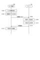
<<2.構成例>>
<2.1.センサ装置100の構成例>
図2は、本実施形態に係るセンサ装置100の論理的な構成の一例を示すブロック図である。図2に示すように、センサ装置100は、検出部110、通信部120、出力部130、記憶部140及び制御部150を含む。 <<2. Configuration example>>
2.1. Example of the configuration of the
2 is a block diagram showing an example of a logical configuration of the
(1)検出部110
検出部110は、車両、車内、搭乗者(運転者又は同乗者)、車両の周囲の環境等に関する多様な情報を検出する。検出部110は、カメラ、レーダ、慣性センサ又は生体情報センサ等の各種センサを有し、検出したセンサ情報を出力する。 (1)
The
(2)通信部120
通信部120は、有線/無線により他の装置との間でデータの送受信を行うための通信モジュールである。例えば、通信部120は、他のセンサ装置100又はサーバ30との間で通信を行う。 (2)
The
(3)出力部130
出力部130は、映像、画像、音声、振動等によって情報を出力する。例えば、センサ装置100が車両に搭載される場合、出力部130は、搭乗者へ情報を出力する。また、センサ装置100が信号機に搭載される場合、出力部130は、周囲の車両の搭乗者又は歩行者へ情報を出力する。 (3)
The
(4)記憶部140
記憶部140は、センサ装置100の動作のためのプログラム及び様々なデータを一時的に又は恒久的に記憶する。 (4)
The
(5)制御部150
制御部150は、センサ装置100の様々な機能を提供する。制御部150は、予測部152及び出力制御部154を含む。なお、制御部150は、これらの構成要素以外の他の構成要素をさらに含み得る。即ち、制御部150は、これらの構成要素の動作以外の動作も行い得る。予測部152及び出力制御部154の動作は、後に詳細に説明する。 (5)
The
<2.2.サーバ30の構成例>
図3は、本実施形態に係るサーバ30の論理的な構成の一例を示すブロック図である。図3に示すように、サーバ30は、通信部310、学習データDB(Data Base)320及び制御部330を含む。 <2.2. Example of configuration of
3 is a block diagram showing an example of a logical configuration of the
(1)通信部310
通信部310は、有線/無線により他の装置との間でデータの送受信を行うための通信モジュールである。例えば、通信部310は、センサ装置100又は外部DB40との間で通信を行う。 (1)
The
(2)学習データDB320
学習データDB320は、学習データを記憶する。学習データは、特徴量ベクトルと事故情報とを含む情報である。事故情報は、システム1に接続するセンサ装置100から取得されてもよいし、外部DB40から取得されてもよい。事故情報は、事故発生の有無、及び発生した場合は事故の内容(地理的位置、事故の種類、発生日時、発生経緯、加害者と被害者の属性、及び事故に関連する車両の識別情報)を含む情報である。外部DB40は、例えば報道機関、交通機関、国などにより運用される、事故情報を蓄積するDBである。なお、本明細書における事故とは、人身事故又は物損事故等のいわゆる交通事故を指すものとする。 (2)
The learning
(3)制御部330
制御部330は、サーバ30の様々な機能を提供する。制御部330は、記憶制御部332及び学習部334を含む。なお、制御部330は、これらの構成要素以外の他の構成要素をさらに含み得る。即ち、制御部330は、これらの構成要素の動作以外の動作も行い得る。記憶制御部332及び学習部334の動作は、後に詳細に説明する。 (3)
The
<<3.技術的特徴>>
続いて、本実施形態に係るシステム1の技術的特徴を説明する。以下では、車両に搭載されたひとつのセンサ装置100に着目して技術的特徴を説明する。センサ装置100が搭載される車両を自車両とも称し、他の車両を他車両とも称する。また、着目するセンサ装置100以外のセンサ装置を、他のセンサ装置とも称する。 <<3. Technical Features>>
Next, technical features of the
(1)事故確率予測
センサ装置100(例えば、予測部152)は、ユーザ(運転者)により運転される車両(自車両)の事故確率を予測する。なお、以下では、特に言及しない限り、運転者とは自車両の運転者を指すものとする。 (1) Accident Probability Prediction The sensor device 100 (e.g., the prediction unit 152) predicts the accident probability of a vehicle (host vehicle) driven by a user (driver). Note that, hereinafter, the driver refers to the driver of the host vehicle unless otherwise specified.
センサ装置100は、運転者又は自車両に関する特徴量に基づいて、事故確率を予測する。これにより、運転者又は自車両に個人化された事故確率の予測を行うことが可能となる。また、センサ装置100は、他車両に関する特徴量に基づいて、事故確率を予測してもよい。これにより、他車両との関係も加味した、運転者又は自車両に個人化された事故確率の予測を行うことが可能となる。事故確率の予測には、ひとつ以上の特徴量の組み合わせである特徴量ベクトルが用いられ得る。特徴量ベクトルの具体例については、後に詳しく説明する。The
センサ装置100は、多様な方法で事故確率を予測する。以下では、一例として、ロジスティック回帰モデルを用いた予測方法について説明する。予測式の一例を、下記の数式(1)に示す。The

ここで、


サーバ30(例えば、記憶制御部332及び学習データDB320)は、各車両(より正確には、各車両に搭載されたセンサ装置100)から送信された特徴量ベクトルxを蓄積する。さらに、サーバ30は、各車両又は外部DB40から送信された事故情報を蓄積する。そのため、サーバ30は、大量の(x,y)のペアを保持することとなる。サーバ30(例えば、学習部334)は、このペアを学習データとして利用することで予測モデル(例えば、パラメータw)を学習する。The server 30 (e.g., the
例えば、所定時間後(例えば、1分後)の事故確率を予測するための予測モデルを学習するための学習データがどのようなものか説明する。学習データは、当該所定時間内(例えば、1分以内)に事故が発生したタイミングで取得された特徴量ベクトルxとy=1とのペアを含む。また、学習データは、当該所定時間内(例えば、1分以内)に事故が発生しなかったタイミングで取得された特徴量ベクトルxとy=0とのペアを含む。For example, we will explain what kind of training data is used to train a prediction model for predicting the probability of an accident after a specified time (e.g., after one minute). The training data includes a pair of feature vectors x and y = 1 obtained when an accident occurs within the specified time (e.g., within one minute). The training data also includes a pair of feature vectors x and y = 0 obtained when no accident occurs within the specified time (e.g., within one minute).
(2)特徴量ベクトル
センサ装置100(例えば、予測部152)は、事故確率の予測に用いる特徴量ベクトルを取得する。特徴量ベクトルは、センサ装置100において生成されてもよいし、他の装置(例えば、サーバ30又は他のセンサ装置100)において生成されてもよい。一例として、センサ装置100において特徴量ベクトルが生成される場合について説明する。例えば、センサ装置100(例えば、予測部152)は、検出部110により検出されたセンサ情報、又は通信部120により他の装置(例えば、他のセンサ装置100又はサーバ30等)から取得された情報に基づいて、特徴量ベクトルを生成する。シンボル特徴量については、one-of-k特徴量ベクトルとして数値ベクトルに変換されるものとする。 (2) Feature Vector The sensor device 100 (e.g., the prediction unit 152) acquires a feature vector used to predict the accident probability. The feature vector may be generated in the
センサ装置100(例えば、予測部152)は、取得したひとつ以上の特徴量ベクトルを連結する。センサ装置100は、この連結した特徴量ベクトルを予測モデルに入力することで、事故確率を予測する。The sensor device 100 (e.g., the prediction unit 152) concatenates one or more acquired feature vectors. The
特徴量ベクトルは、例えば運転特徴量ベクトル又は属性特徴量ベクトルに分類され得る。運転特徴量ベクトルとは、リアルタイムに検出されるセンサ情報に基づく特徴量ベクトルである。具体的には、運転特徴量ベクトルは、所定期間(10秒など)ごとのリアルタイムな運転に関する特徴量ベクトルであってもよい。運転特徴量ベクトルが事故確率の予測に用いられることにより、リアルタイムな状況に応じた事故確率の予測が可能となる。属性特徴量ベクトルとは、蓄積又は登録された情報に基づく特徴量ベクトルである。具体的には、属性特徴量ベクトルは、運転者又は自車両の性質に関する特徴量ベクトルであってもよい。属性特徴量ベクトルが事故確率の予測に用いられることにより、運転者又は自車両の性質に応じた事故確率の予測が可能となる。The feature vector can be classified into, for example, a driving feature vector or an attribute feature vector. The driving feature vector is a feature vector based on sensor information detected in real time. Specifically, the driving feature vector may be a feature vector related to real-time driving for a predetermined period (e.g., 10 seconds). By using the driving feature vector to predict the accident probability, it becomes possible to predict the accident probability according to the real-time situation. The attribute feature vector is a feature vector based on accumulated or registered information. Specifically, the attribute feature vector may be a feature vector related to the characteristics of the driver or the vehicle. By using the attribute feature vector to predict the accident probability, it becomes possible to predict the accident probability according to the characteristics of the driver or the vehicle.
特徴量ベクトルは、事故確率の予測モデルの学習にも用いられ得る。そのために、センサ装置100(例えば、通信部120)は、定期的にセンサ情報又は特徴量ベクトルをサーバ30へ送信する。その際、センサ装置100は、自車両の識別情報、事故の有無及び事故が発生した場合はその内容を示す情報に対応付けて、センサ情報又は特徴量ベクトルを送信するものとする。The feature vector can also be used to learn a prediction model for accident probability. To that end, the sensor device 100 (e.g., the communication unit 120) periodically transmits the sensor information or the feature vector to the
センサ装置100(例えば、通信部120)は、事故確率の予測結果が閾値以上であった時間帯におけるセンサ情報又は特徴量ベクトルのみを送信してもよい。また、センサ装置100は、事故又は後述する予兆現象が発生した時刻の前後の所定時間帯におけるセンサ情報又は特徴量ベクトルのみを送信してもよい。これらにより、データ送信量を削減することが可能である。また、事故又はその予兆現象が発生していない学習データに、予測モデルが過度に適合することが防止される。The sensor device 100 (e.g., the communication unit 120) may transmit only sensor information or feature vectors for a time period in which the predicted accident probability was equal to or greater than a threshold value. The
以下、運転特徴量ベクトル及び属性特徴量ベクトルについて具体的に説明する。The driving feature vector and attribute feature vector are explained in detail below.
(2.1)運転特徴量ベクトル
運転特徴量ベクトルに含まれ得る特徴量ベクトルの項目の一例を、以下に示す。運転特徴量ベクトルは、以下に一例を示した特徴量ベクトルをひとつ以上連結することにより生成される。 (2.1) Driving Feature Vector An example of a feature vector item that may be included in the driving feature vector is shown below. The driving feature vector is generated by concatenating one or more of the feature vectors shown below as examples.
(外部物体情報)
外部物体情報は、カメラ又はレーダ等により検出される、自車両の外部に存在する物体に関する特徴量ベクトルである。外部物体情報は、例えば物体の座標、大きさ、速度及び向き、加速度及び向き、情報の信頼度、並びに検出時刻を含み得る。 (External object information)
The external object information is a feature vector related to an object present outside the vehicle, detected by a camera, a radar, etc. The external object information may include, for example, the coordinates, size, speed and direction, acceleration and direction, reliability of the information, and detection time of the object.
(車両運動情報)
車両運動情報は、加速度センサ等により検出される、自車両の運動状態を示す特徴量ベクトルである。車両運動情報は、例えば自車両の速度、加速度、及びそれらの向きを含み得る。 (Vehicle movement information)
The vehicle motion information is a feature vector that indicates the motion state of the host vehicle, detected by an acceleration sensor, etc. The vehicle motion information may include, for example, the speed, acceleration, and orientations of the host vehicle.
(車両操作情報)
車両操作情報は、運転者による自車両の操作状態を示す特徴量ベクトルである。車両操作情報は、例えば下記の情報を含み得る。
・ウィンカーが動作しているか否か
・ワイパーが動作しているか否か
・各ミラーの角度
・各窓が開放されているか否か、及び開放の割合
・ライトが点灯しているか否か
・シフトレバーの位置
・ブレーキを踏んでいる度合
・アクセルを踏んでいる度合
・クラッチペダルを踏んでいるか否か (Vehicle operation information)
The vehicle operation information is a feature vector that indicates the state of operation of the vehicle by the driver. The vehicle operation information may include, for example, the following information:
・Whether the blinkers are working ・Whether the wipers are working ・The angle of each mirror ・Whether each window is open and the degree to which it is open ・Whether the lights are on ・The position of the shift lever ・How hard the brake is being pressed ・How hard the accelerator is being pressed ・Whether the clutch pedal is being pressed
(生体情報)
生体情報は、搭乗者(特に、運転者)の生体的な情報を示す特徴量ベクトルである。生体情報は、例えば血圧、心拍数、体温、血糖、及び発汗量を示す情報を含み得る。生体情報は、車内に設けられた生体情報センサに検出され得る。あるいは、生体情報は、搭乗者が保持するモバイルデバイスに設けられた生体情報センサにより検出され、システム1(例えば、搭乗する車両に搭載されたセンサ装置100)に送信され得る。生体情報は、計測値の時系列変化の平均値などの統計量であってもよい。 (Biometric information)
The biometric information is a feature vector indicating the biometric information of a passenger (particularly, a driver). The biometric information may include, for example, information indicating blood pressure, heart rate, body temperature, blood sugar, and sweat rate. The biometric information may be detected by a biometric sensor provided in the vehicle. Alternatively, the biometric information may be detected by a biometric sensor provided in a mobile device held by the passenger, and transmitted to the system 1 (for example, the
(生体状態情報)
生体状態情報は、生体情報に基づいて推定される、搭乗者の状態を示す特徴量ベクトルである。生体状態情報は、集中度、空腹度、眠気の度合等を示す情報を含み得る。これらの情報は、例えば血糖値、瞬きの頻度、視線のブレの度合等に基づいて推定され得る。 (Biological condition information)
The biological condition information is a feature vector that indicates the state of the occupant, estimated based on the biological information. The biological condition information may include information indicating the concentration level, hunger level, degree of drowsiness, etc. This information may be estimated based on, for example, blood glucose level, blink frequency, degree of gaze blur, etc.
(車内環境情報)
車内環境情報は、車内環境を示す特徴量ベクトルである。車内環境情報は、例えば乗車人数を示す情報を含み得る。乗車人数を示す情報は、例えば車内のカメラ又は座面に設けられた感圧センサによって認識され得る。車内環境情報は、例えば温度、湿度、気圧を示す情報を含み得る。車内環境情報は、例えば窓のくもり具合を示す情報を含み得る。窓のくもり具合を示す情報は、例えば車内のカメラにより撮像された窓の撮像画像に基づいて認識され得る。車内環境情報は、例えば会話中か否かを示す情報を含み得る。会話中か否かを示す情報は、例えば車内のマイクにより収集された音声に基づいて認識され得る。車内環境情報は、例えば音楽の音量を示す情報を含み得る。音楽の音量を示す情報は、例えばカーステレオの設定値であってもよいし、車内のマイクにより収集された音声に基づいて認識されてもよい。車内環境情報は、計測値の時系列変化の平均値などの統計量であってもよい。 (In-vehicle environment information)
The in-vehicle environment information is a feature vector indicating the in-vehicle environment. The in-vehicle environment information may include, for example, information indicating the number of passengers. The information indicating the number of passengers may be recognized, for example, by a camera in the vehicle or a pressure sensor provided on the seat. The in-vehicle environment information may include, for example, information indicating temperature, humidity, and air pressure. The in-vehicle environment information may include, for example, information indicating the degree of fogging of the windows. The information indicating the degree of fogging of the windows may be recognized, for example, based on an image of the window captured by a camera in the vehicle. The in-vehicle environment information may include, for example, information indicating whether or not a conversation is taking place. The information indicating whether or not a conversation is taking place may be recognized, for example, based on a voice collected by a microphone in the vehicle. The in-vehicle environment information may include, for example, information indicating the volume of music. The information indicating the volume of music may be, for example, a setting value of a car stereo, or may be recognized based on a voice collected by a microphone in the vehicle. The in-vehicle environment information may be a statistic such as an average value of a time series change in a measurement value.
(運転者物理状態情報)
運転者物理状態情報は、運転者の物理的な状態を示す特徴量ベクトルである。運転者物理状態情報は、例えば運転者の視線を示す情報を含み得る。運転者の視線を示す情報は、例えば、所定期間の眼球の動き、瞳孔の状態とその変化を示す情報であってもよく、眼球を撮像した撮像画像に基づく画像認識により認識され得る。運転者物理状態情報は、例えばハンドルの切り方を示す情報を含み得る。ハンドルの切り方を示す情報は、例えばハンドルの切り方のパターンを示す情報であってもよく、ハンドルの角速度の時系列変化の平均値などの統計量であってもよい。運転者物理状態情報は、例えばハンドルの握り方を示す情報を含み得る。ハンドルの握り方を示す情報は、例えば両手で握っているか否か、又は握り場所を示す情報であってもよく、画像認識又はハンドルに設けられたセンサにより認識され得る。運転者物理状態情報は、例えば運転者の姿勢を示す情報を含み得る。運転者の姿勢を示す情報は、例えば座席の状態(座面及び背面の位置及び角度)を示す情報であってもよく、座席に設けられたセンサにより認識され得る。運転者物理状態情報は、例えば運転者がシートベルトを装着しているか否かを示す情報であってもよく、シートベルトの留め具に設けられたセンサにより認識され得る。 (Driver physical state information)
The driver physical state information is a feature vector indicating the physical state of the driver. The driver physical state information may include, for example, information indicating the line of sight of the driver. The information indicating the line of sight of the driver may be, for example, information indicating the movement of the eyeballs over a predetermined period of time, the state of the pupils and their changes, and may be recognized by image recognition based on an image of the eyeballs. The driver physical state information may include, for example, information indicating the way the steering wheel is turned. The information indicating the way the steering wheel is turned may be, for example, information indicating the pattern of how the steering wheel is turned, or may be a statistic such as the average value of the time-series change in the angular velocity of the steering wheel. The driver physical state information may include, for example, information indicating the way the steering wheel is gripped. The information indicating the way the steering wheel is gripped may be, for example, information indicating whether the steering wheel is gripped with both hands or information indicating the gripping location, and may be recognized by image recognition or a sensor provided on the steering wheel. The driver physical state information may include, for example, information indicating the driver's posture. The information indicating the driver's posture may be, for example, information indicating the state of the seat (the position and angle of the seat surface and backrest), and may be recognized by a sensor provided on the seat. The driver physical state information may be, for example, information indicating whether the driver is fastening a seat belt, and can be recognized by a sensor provided on a seat belt fastener.
(天候情報)
天候情報は、自車両の走行場所の天候を示す特徴量ベクトルである。天候情報は、例えば下記の情報を含み得る。
・降雨、降雪の有無
・気温、湿度
・霧の有無 (Weather information)
The weather information is a feature vector that indicates the weather at the location where the vehicle is traveling. The weather information may include, for example, the following information:
- Presence or absence of rain or snow - Temperature, humidity - Presence or absence of fog
(走行路情報)
走行路情報は、自車両の走行路の状態を示す特徴量ベクトルである。走行路情報は、例えば車外カメラにより撮像された撮像画像の画像認識結果、又は地図情報に基づいて認識され得る。走行路情報は、例えば下記の情報を含み得る。
・坂か否か
・高速道路か否か
・橋か否か
・走行路が舗装されているか否か (Road information)
The road information is a feature vector that indicates the state of the road on which the vehicle is traveling. The road information may be recognized based on, for example, an image recognition result of an image captured by an external camera or map information. The road information may include, for example, the following information:
- Is it a hill? - Is it a highway? - Is it a bridge? - Is the road paved?
(地図に紐付く事故情報)
地図に紐付く事故情報は、過去に発生した事故を示す特徴量ベクトルであり、事故発生場所の位置情報が対応付けられた情報を含む。例えば、ある交差点又はカーブの特徴量ベクトルは、当該交差点又はカーブの所定距離内で発生した事故情報の各項目から作成及び連結される。事故確率予測の際に用いられる特徴量ベクトルは、自車両が所定時間内に通過すると予測される交差点又はカーブの特徴量ベクトルの和をとったものが採用され得る。なお、自車両が所定時間内に通過すると予測される交差点又はカーブは、道なりの直進を仮定し、自車両の予測時の速度を維持した場合に通過すると予測される交差点又はカーブであるものとする。 (Accident information linked to maps)
The accident information linked to the map is a feature vector indicating accidents that have occurred in the past, and includes information associated with location information of the accident location. For example, the feature vector of a certain intersection or curve is created and linked from each item of accident information that has occurred within a predetermined distance of the intersection or curve. The feature vector used when predicting the accident probability may be the sum of the feature vectors of intersections or curves that the vehicle is predicted to pass through within a predetermined time. The intersections or curves that the vehicle is predicted to pass through within a predetermined time are assumed to be intersections or curves that the vehicle is predicted to pass through if it continues traveling straight along the road and maintains the predicted speed of the vehicle.
(累積運転時間情報)
累積運転時間情報は、運転者の運転時間の累積値を示す特徴量ベクトルである。例えば、運転時間の累積値は、直前の駐車からの累積値であり得る。 (Cumulative driving time information)
The cumulative driving time information is a feature vector indicating a cumulative value of the driving time of the driver. For example, the cumulative value of the driving time may be a cumulative value from the last parking.
(2.2)属性特徴量ベクトル
属性特徴量ベクトルに含まれ得る特徴量ベクトルの項目の一例を、以下に示す。属性特徴量ベクトルは、以下に一例を示した特徴量ベクトルをひとつ以上連結することにより生成される。 (2.2) Attribute Feature Vector An example of an item of a feature vector that may be included in the attribute feature vector is shown below. The attribute feature vector is generated by concatenating one or more of the feature vectors shown below as examples.
(運転履歴情報)
運転履歴情報は、運転者の直近の所定期間(例えば、1年)における運転の履歴を示す特徴量ベクトルである。運転の履歴を示す情報としては、例えば自車両の速度、走行経路、ブレーキのタイミング等の情報を含み得る。運転履歴情報は、計測値の時系列変化の平均値などの統計量であってもよい。運転履歴情報は、運転者に紐付いていてもよいし、自車両に紐付いていてもよい。 (Driving history information)
The driving history information is a feature vector indicating the driving history of the driver in a recent predetermined period (e.g., one year). The information indicating the driving history may include, for example, information such as the speed of the vehicle, the driving route, and the timing of braking. The driving history information may be a statistical quantity such as an average value of the time series changes of the measured values. The driving history information may be linked to the driver or to the vehicle.
(運転者属性情報)
運転者属性情報は、運転者の属性情報の特徴量ベクトルである。運転者属性情報は、例えば運転者の運転経験年数、年齢、及び性別等を含み得る。 (Driver attribute information)
The driver attribute information is a feature vector of the driver's attribute information, and may include, for example, the number of years of driving experience, the age, and the gender of the driver.
(車両属性情報)
車両属性情報は、自車両の属性情報の特徴量ベクトルである。車両属性情報は、例えば車種、モデル名、燃費、製造年、及び過去の修理履歴等を含み得る。 (Vehicle attribute information)
The vehicle attribute information is a feature vector of the attribute information of the vehicle itself, and may include, for example, the vehicle type, model name, fuel efficiency, manufacturing year, and past repair history.
(運転習熟度情報)
運転習熟度情報は、運転者の運転習熟度を示す特徴量ベクトルである。運転習熟度情報は、例えば5段階評価であり、運転者により自己申告され得る。センサ装置100(例えば、制御部150)は、自己申告しない運転者については、回帰モデルにより運転習熟度を設定し得る。そのために、センサ装置100は、運転習熟度を目的変数とし、入力を運転履歴情報及び運転者属性情報とし、回帰モデルを機械学習により作成しておく。 (Driving proficiency information)
The driving proficiency information is a feature vector indicating the driving proficiency of the driver. The driving proficiency information is, for example, a five-point scale and can be self-reported by the driver. For drivers who do not self-report, the sensor device 100 (e.g., the control unit 150) can set the driving proficiency using a regression model. To this end, the
(運転者のくせ情報)
運転者のくせ情報は、運転者のくせを示す特徴量ベクトルである。運転者のくせ情報は、例えば複数の運転者の運転履歴情報についてのクラスタリング結果における、対象の運転者の所属クラスタのIDである。クラスタリングは、例えばサーバ30において行われ得る。クラスタリングは、一部の運転者に対しくせラベルをあらかじめ定義し、それぞれのくせラベルについて入力を運転履歴情報とした分類問題として分類モデルを機械学習で学習し、運転者にくせラベルを付与することで行われ得る。具体的なくせとしては、例えば車線変更が多い、運転が荒い、等が挙げられる。 (Driver Habit Information)
The driver's habit information is a feature vector indicating the driver's habit. The driver's habit information is, for example, an ID of a cluster to which the target driver belongs in a clustering result of driving history information of a plurality of drivers. Clustering can be performed, for example, in the
(2.3)補足
事故確率の予測時には、例えばセンサ装置100(例えば、予測部152)は、上述した各特徴量ベクトルを連結して用いる。その際、事故確率の予測時に現に取得された特徴量ベクトルが連結されてもよいし、予測対象時刻(例えば、1分後など)に取得されると予測される特徴量ベクトルが連結されてもよい。 (2.3) Supplementary Note When predicting the accident probability, for example, the sensor device 100 (e.g., the prediction unit 152) concatenates and uses the above-mentioned feature vectors. In this case, the feature vectors actually acquired when predicting the accident probability may be concatenated, or the feature vectors predicted to be acquired at the prediction target time (e.g., one minute later) may be concatenated.
また、センサ装置100は、自車両の特徴量ベクトルだけでなく、近傍の他車両の特徴量ベクトルを連結して用いてもよい。例えば、所定時間後(例えば、30秒後)に近傍(例えば100m以内)に入ると予測される(道なりの直進を仮定し、現在の速度を維持した場合に通過する)ひとつ以上の他車両の特徴量ベクトルの和を連結してもよい。The
また、特徴量ベクトルのペアが、ひとつの特徴量ベクトルとして取り扱われてもよい。例えば、運転者のくせ情報と地図に紐付く事故情報との組み合わせにより、特定の事故に繋がり易い特定の運転者のくせが表現でき、事故確率予測の精度が向上し得る。Furthermore, a pair of feature vectors may be treated as a single feature vector. For example, by combining driver habit information with accident information linked to a map, it is possible to express the habits of specific drivers that are likely to lead to specific accidents, thereby improving the accuracy of accident probability prediction.
(3)学習
サーバ30(例えば、学習部334)は、センサ装置100が事故確率を予測する際に用いる予測モデルを学習する。 (3) Learning The server 30 (for example, the learning unit 334) learns a prediction model used by the
例えば、サーバ30は、学習データDB320に蓄積された特徴量ベクトルと事故発生有無を示す情報とのペアに基づいて、上記数式(1)におけるパラメータwを学習する。そして、サーバ30(例えば、通信部310)は、学習結果を示す情報(例えば、パラメータw)を、システム1に接続する全てのセンサ装置100へ通知する。複数のセンサ装置100間では、共通した予測モデルが用いられることとなるが、特徴量ベクトルが個人化されているため、個人化された事故確率の予測が可能である。For example, the
センサ装置100(例えば、記憶部140)は、サーバ30から通知された学習結果を示す情報を記憶する。そして、予測時には、センサ装置100(例えば、予測部152)は、記憶した情報を用いて予測モデルを構築する。そのため、センサ装置100は、予測時にサーバ30と通信しなくてもよい。The sensor device 100 (e.g., the memory unit 140) stores information indicating the learning results notified from the
サーバ30は、事故の他、急ハンドル又は急ブレーキ等の事故の予兆現象(いわゆるヒヤリハット)の発生確率も加味して予測モデルを学習してもよい。これにより、センサ装置100(例えば、予測部152)は、事故の予兆現象の発生確率を加味して学習された予測モデルを用いて事故確率を予測することとなる。事故確率の予測結果が運転者に通知(典型的には、警告)されることを考慮すれば、事故だけでなくその予兆現象の発生をも防止することが可能となり、自車両の安全性をより向上させることができる。ここで、予兆現象を事故確率の予測に加味した予測モデルの生成のために、センサ装置100は、自車両の識別情報、予兆現象の有無、及び予兆現象が発生した場合はその内容を示す情報に対応付けて、センサ情報又は特徴量ベクトルをサーバ30へ送信するものとする。The
なお、急ハンドルに関しては、ハンドルの回転加速度の変化と自車両の加速度及び向きの変化とが、それぞれ閾値以上となった場合に急ハンドルであると判定され得る。急ブレーキに関しては、ブレーキペダルの踏込度の変化と自車両の加速度の変化とが、それぞれ閾値以上となった場合に急ブレーキであると判定され得る。なお、事故の予兆現象には、他にも、信号無視、エンスト、脱輪、スリップ、又はハイドロプレーニング現象等が含まれてもよい。Abrupt steering can be determined when the change in the steering wheel rotation acceleration and the change in the vehicle's acceleration and direction are equal to or greater than a threshold. Sudden braking can be determined when the change in the brake pedal depression and the change in the vehicle's acceleration are equal to or greater than a threshold. Precursors of accidents may also include ignoring traffic signals, stalling, running off the road, slipping, hydroplaning, etc.
予兆現象を事故確率の予測に利用する方法の一例を以下に説明する。An example of how precursor phenomena can be used to predict accident probability is described below.
・第1の例
例えば、サーバ30(例えば、学習部334)は、事故確率の予測モデルと同様にして、予兆現象の発生確率の予測モデル(例えば、数式(1)と同様のモデル)を学習する。次いで、サーバ30は、予兆現象の発生確率を特徴量ベクトルに含めて、事故確率に係る予測モデルを学習する。センサ装置100(例えば、予測部152)は、まず、予兆現象の発生確率を予測し、次いで、予兆現象の発生確率を特徴量ベクトルに連結して、事故確率の予測を行う。 First Example For example, the server 30 (e.g., the learning unit 334) learns a prediction model for the probability of occurrence of a precursor phenomenon (e.g., a model similar to Equation (1)) in a similar manner to the prediction model for the probability of an accident. Next, the
・第2の例
例えば、サーバ30(例えば、学習部334)は、予兆現象の発生確率の予測を事故確率の予測の別タスクとみなし、転移学習を行う。ここで、予兆現象が発生するか否かを示す
サーバ30は、事故確率の予測モデルと同様に、予兆現象の発生確率の予測モデルをロジスティック回帰モデルにより学習する。学習の結果得られたパラメータをw´とする。サーバ30は、事故確率の予測モデルの学習の際に、次式の評価関数を用いる。Similar to the accident probability prediction model, the

ここで、nは学習データの数であり、αは任意の定数である。上記の第1項は尤度である。上記の第2項により、サーバ30は、予兆現象の発生確率の予測モデルを考慮した状態で(予測モデルとしての出力が離れすぎないように)、事故確率の予測モデルを学習することができる。Here, n is the number of training data, and α is an arbitrary constant. The first term above is the likelihood. The second term above enables the
(4)ユーザインタフェース
センサ装置100は、事故確率の予測結果に関する情報を出力する(例えば、出力制御部154が出力部130に出力させる)。以下、センサ装置100が車両に搭載される場合のUI例を、図4~13を参照して説明する。図4~図13は、本実施形態に係るUI例を説明するための図である。 (4) User Interface The
(4.1)事故確率そのものに関するUI
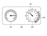
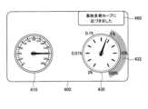
センサ装置100は、事故確率を示す情報を運転者へ出力してもよい。これにより、運転者は、事故確率の上下動をリアルタイムに把握しながら運転を行うことができる。UI例を、図4に示した。図4に示した例では、インストルメントパネル400(出力部130)に、速度メーター410及び事故確率メーター420が配置されている。事故確率メーター420には、円の縁に沿って0から10までの目盛が設けられている。事故確率メーター420は、予測された事故確率(0から1まで)を10倍した値に対応する目盛を、円の中心を軸とする指針421で指すことにより、事故確率を出力する。事故確率メーター420では、値が高い領域422が強調されている。 (4.1) UI for accident probability itself
The
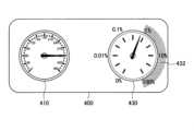
センサ装置100は、事故確率を対数スケールで出力してもよい。事故が発生する頻度が一般的に低いことを考慮すれば、事故確率が0%に近い値から突然100%に近い値に切り替わって見えてしまうことが、対数表現されることにより防止される。UI例を、図5に示した。図5に示した例では、インストルメントパネル400(出力部130)に、速度メーター410及び事故確率メーター430が配置されている。事故確率メーター430では、円の縁の目盛が示すように、事故確率が対数スケールで表現されている。事故確率メーター430でも、値が高い領域432が強調されている。The
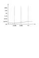
センサ装置100は、事故確率の時系列推移を示す情報を出力してもよい。これにより、運転者は、過去から現在にかけての事故確率の上下動をリアルタイムに把握しながら運転を行うことができる。さらに、センサ装置100は、将来の事故確率の予測結果に基づいて、現在から将来にかけての事故確率の時系列推移を出力してもよい。UI例を、図6に示した。図6示すUIは、事故確率の時系列推移を示している。縦軸は事故確率であり、横軸は時間である。図6に示すUIは、例えばインストルメントパネル又はカーナビゲーションシステムに設けられたディスプレイに表示され得る。The
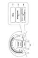
センサ装置100は、事故確率の累積値に基づく情報を出力してもよい。例えば、まず、センサ装置100は、運転開始から90分等の予め定めた基準値から、集中度、空腹度又は眠気等の生体状態情報に基づく補正項を減算又は加算等することで、運転継続可能時間を算出する。そして、センサ装置100は、運転開始からの事故確率の累積値を算出し、累積値が大きいほど運転継続可能時間を減らして、又は運転継続可能時間に基づき算出される運転継続可能距離を減らして出力する。このような出力により、運転者は、累積値が大きくなるにつれて運転へのより高い集中又は休憩を促されることとなり、安全性をより向上させることができる。UI例を、図7に示した。図7に示すUIでは、速度メーター410の中央部に設けられたディスプレイ440の上部441に燃料の残量に基づき算出される航続可能距離が表示され、下部442に上述した運転継続可能時間が表示されている。事故確率の累積値に基づく表示項目としては、他に、残り体力値(HP)示す項目443、運転継続可能距離を示す項目444、目的地に到着するまでに必要な休憩回数を示す項目445が考えられる。The
センサ装置100は、地図上に事故確率に関する情報を出力してもよい。例えば、センサ装置100は、属性特徴量モデルのみを利用して構築された予測モデルを用いて、交差点又はカーブの事故確率を予測し、事故確率が閾値を超える地点を示す情報を出力する。その場合、「地図に紐付く事故情報」の特徴量ベクトルが、走行予定経路上の交差点又はカーブに合わせて更新された後に、事故確率が予測されることが望ましい。事故確率が閾値を超える地点を示す情報が出力されることにより、事故が発生しやすい場所に関し運転者に注意を促すことができ、安全性を向上させることができる。同様の趣旨で、過去に事故が発生した場所を示す情報が出力されてもよい。また、センサ装置100は、事故確率が低い経路を示す情報を出力してもよい。その場合に、運転者に安全な経路を走行するよう促すことができ、安全性を向上させることができる。同様の趣旨で、過去に事故が発生していない又は発生回数が少ない経路を示す情報が出力されてもよい。UI例を、図8及び図9に示した。図8に示すUIでは、自車両の現在位置450、走行予定経路451、及び事故確率が閾値を超える地点452が地図上に表示されている。また、また、図8に示すUIでは、事故確率が閾値を超える地点452が存在することを警告するメッセージ453が表示されている。図9に示すUIでは、自車両の現在位置450、走行予定経路451、過去に事故が多く発生した地点455、及び事故確率が低い経路454が地図上に表示されている。また、図9に示すUIでは、過去に事故が多く発生した地点455が存在することを示すメッセージ457、及び事故確率が低い経路454が存在することを示すメッセージ456が表示されている。このように、地図上に事故確率に関する情報(例えば、事故確率が閾値を超える地点又は事故確率が低い経路等)が強調表示されることで、より安全性を向上させることができる。The
(4.2)事故確率の上昇要因に関するUI
センサ装置100は、事故確率を上昇させた要因に応じた情報を運転者へ出力してもよい。例えば、センサ装置100は、要因を示す情報を出力する。これにより、運転者に、事故確率を上昇させた要因を認識させて注意を促すことが可能となり、安全性を向上させることが可能となる。要因は、特徴量そのものであってもよいし、特徴量から推定される情報であってもよいし、特徴量に対応するセンサの種類から推定される情報であってもよい。事故確率を上昇させた要因は複数存在する場合がある。その場合、センサ装置100は、ひとつ以上の要因から事故確率の上昇への寄与度に応じて選定した要因を示す情報を出力してもよい。具体的には、センサ装置100は、事故確率の上昇への寄与度が大きい要因(例えば、寄与度が閾値を超える要因、又は寄与度が上位の所定個の要因)を示す情報を出力してもよい。例えば、上記数式(1)を用いた事故確率の算出に際して、事故確率の上昇への寄与度が大きい特徴量そのもの、当該特徴量から推定される情報、又は当該特徴量に対応するセンサの種類から推定される情報が、出力され得る。予測にロジスティック回帰モデルが利用されている場合、特徴量の値とその特徴量に該当するパラメータの値の積が、寄与値とされてもよい。このような出力により、運転者に、特に上昇幅が高い要因を認識させて注意を促すことが可能となり、安全性を向上させることができる。UI例を、図10に示した。図10に示すUIでは、図5に示したUIにおいて、事故確率の上昇の要因を示すメッセージ460が表示されている。メッセージの他に、例えば要因ごとに予め定められたアイコンが表示されてもよい。 (4.2) UI for factors increasing accident probability
The
センサ装置100は、事故確率を低下させるために運転者が行うべき行動を指示する情報を出力してもよい。具体的には、センサ装置100は、上記説明した事故確率を上昇させた要因を取り除くためのメッセージを出力する。これにより、運転者に具体的な行動を促すことが可能となり、安全性を向上させることができる。UI例を、図11に示した。図11に示すUIでは、図10に示したUIにおいて、事故確率を低下させるために運転者が行うべき行動を指示するメッセージ461が表示されている。The
(4.3)その他
センサ装置100は、他にも多様なUIを提供し得る。その一例を、図12及び図13に示した。 (4.3) Others The
図12に示したUIでは、運転状況に対応する音声メッセージ471が、ディスプレイ470に表示されたキャラクターから発せられたかのようにフィードバックされる。例えば、センサ装置100は、急な加速及び急ブレーキ等の事故に繋がり得る危険な操作に対し運転者を責めるようなフィードバックを行い、安全運転に対し運転者を褒めるようなフィードバックを行う。このようなフィードバックにより、運転者は、ゲーム感覚で安全運転を心がけることができる。In the UI shown in FIG. 12, a
図13に示したUIでは、自車両480と他車両481A~481Cとの位置関係、及び仮に事故を起こした場合の過失の割合を示す情報482A~482Cが出力されている。例えば、情報482Aによれば、自車両480と他車両481Aとが事故を起こした場合の過失の割合は、自車両480が10で他車両481Aが0となることが予測されている。また、情報482Bによれば、自車両480が0で他車両481Aが10となることが予測されている。また、情報482Cによれば、自車両480が7で他車両481Aが3となることが予測されている。このようなUIにより、運転者は、どの他車両に気を付けるべきかを視覚的に把握することができる。なお、図13に示すUIは、例えばインストルメントパネル又はカーナビゲーションシステムに設けられたディスプレイに表示され得る。In the UI shown in FIG. 13,
<<4.処理の流れ>>
続いて、図14~図18を参照して、本実施形態に係るシステム1において実行される処理の流れの一例を説明する。 <<4. Processing flow>>
Next, an example of the flow of processing executed in the
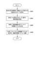
(予測モデル学習処理)
図14は、本実施形態に係るシステム1において実行される予測モデル学習処理の流れの一例を示すシーケンス図である。本シーケンスには、センサ装置100及びサーバ30が関与する。 (Prediction model learning process)
14 is a sequence diagram showing an example of the flow of a prediction model learning process executed in the
図14に示すように、まず、センサ装置100(例えば、検出部110)は、センサ情報を検出する(ステップS102)。次いで、センサ装置100(例えば、予測部152)は、検出したセンサ情報に基づいて特徴量ベクトルを生成する(ステップS104)。次に、センサ装置100(例えば、通信部120)は、生成した特徴量ベクトルをサーバ30へ送信する(ステップS106)。図14では省略されているが、システム1に接続する複数のセンサ装置100が、特徴量ベクトルをサーバ30へ送信する。As shown in FIG. 14, first, the sensor device 100 (e.g., the detection unit 110) detects sensor information (step S102). Next, the sensor device 100 (e.g., the prediction unit 152) generates a feature vector based on the detected sensor information (step S104). Next, the sensor device 100 (e.g., the communication unit 120) transmits the generated feature vector to the server 30 (step S106). Although omitted in FIG. 14,
次いで、サーバ30(例えば、記憶制御部332及び学習データDB320)は、ひとつ以上のセンサ装置100から受信した特徴量ベクトルを、車両の識別情報、事故発生の有無、及び事故の内容に対応付けた情報を、学習データとして記憶する(ステップS108)。そして、サーバ30(例えば、学習部334)は、学習データから予測モデルを学習する(ステップS110)。予測モデルが数式(1)に示したロジスティック回帰モデルである場合、サーバ30は、パラメータwを学習する。次に、サーバ30(例えば、通信部310)は、学習結果を示す情報(例えば、パラメータw)を、配下の全てのセンサ装置100へ送信する(ステップS112)。Then, the server 30 (e.g., the
そして、センサ装置100(例えば、予測部152)は、受信した学習結果を示す情報に基づいて、予測モデルを更新する(ステップS114)。例えば、予測部152は、予測モデルのパラメータを受信したパラメータに更新する。Then, the sensor device 100 (e.g., the prediction unit 152) updates the prediction model based on the received information indicating the learning result (step S114). For example, the
以上により処理は終了する。The process is now complete.
(事故確率予測処理)
図15は、本実施形態に係るセンサ装置100において実行される事故確率予測処理の流れの一例を示すフローチャートである。 (Accident probability prediction processing)
FIG. 15 is a flowchart showing an example of the flow of an accident probability prediction process executed in the
図15に示すように、まず、センサ装置100(例えば、検出部110)は、センサ情報を検出する(ステップS202)。次いで、センサ装置100(例えば、予測部152)は、検出したセンサ情報に基づいて特徴量ベクトルを生成する(ステップS204)。なお、このとき生成される特徴量ベクトルには、自車両の運転者又は自車両の特徴量ベクトルだけでなく、他車両の運転者又は他車両の特徴量ベクトルが含まれていてもよい。次に、センサ装置100(例えば、予測部152)は、予測モデルに特徴量ベクトルを入力して、事故確率を予測する(ステップS206)。そして、センサ装置100(例えば、出力制御部154)は、出力処理を行う(ステップS208)。例えば、出力制御部154は、事故確率そのものに関するUI又は事故確率の上昇要因に関するUIを出力部130に出力させる。As shown in FIG. 15, first, the sensor device 100 (e.g., the detection unit 110) detects sensor information (step S202). Next, the sensor device 100 (e.g., the prediction unit 152) generates a feature vector based on the detected sensor information (step S204). The feature vector generated at this time may include not only the feature vector of the driver of the vehicle or the vehicle itself, but also the feature vector of the driver of the other vehicle or the other vehicle. Next, the sensor device 100 (e.g., the prediction unit 152) inputs the feature vector into a prediction model to predict the accident probability (step S206). Then, the sensor device 100 (e.g., the output control unit 154) performs output processing (step S208). For example, the
以上により処理は終了する。The process is now complete.
(特徴量ベクトル生成処理)
図16は、本実施形態に係るセンサ装置100において実行される特徴量ベクトル生成処理の流れの一例を示すフローチャートである。本フローは、上記ステップS104及びステップS204における処理に相当する。 (Feature vector generation process)
16 is a flowchart showing an example of the flow of the feature vector generation process executed in the
図16に示すように、まず、センサ装置100(例えば、予測部152)は、直近のセンサ情報に基づいて運転特徴量ベクトルを生成する(ステップS302)。次いで、センサ装置100(例えば、予測部152)は、運転特徴量ベクトルに基づいて、属性特徴量ベクトルを更新する(ステップS304)。そして、センサ装置100(例えば、予測部152)は、運転特徴量ベクトル及び属性特徴量ベクトルを連結する(ステップS306)。As shown in FIG. 16, first, the sensor device 100 (e.g., the prediction unit 152) generates a driving feature vector based on the most recent sensor information (step S302). Next, the sensor device 100 (e.g., the prediction unit 152) updates the attribute feature vector based on the driving feature vector (step S304). Then, the sensor device 100 (e.g., the prediction unit 152) concatenates the driving feature vector and the attribute feature vector (step S306).
以上により処理は終了する。The process is now complete.
続いて、個々の特徴量ベクトルの生成処理の一例として、地図に紐付く事故情報に関する特徴量ベクトルの生成処理、及び予兆現象の発生確率に関する特徴量ベクトルの生成処理について説明する。Next, as an example of the process of generating individual feature vectors, we will explain the process of generating feature vectors related to accident information linked to a map, and the process of generating feature vectors related to the probability of occurrence of a precursor phenomenon.
図17は、本実施形態に係るセンサ装置100において実行される地図に紐付く事故情報に関する特徴量ベクトル生成処理の流れの一例を示すフローチャートである。Figure 17 is a flowchart showing an example of the flow of a feature vector generation process for accident information linked to a map executed by the
図17に示すように、まず、センサ装置100(例えば、予測部152)は、将来の所定期間内に通過すると予測される交差点又はカーブを特定する(ステップS402)。次いで、センサ装置100(例えば、予測部152)は、特定した交差点又はカーブに紐付く事故情報をサーバ30から取得する(ステップS404)。次いで、センサ装置100(例えば、予測部152)は、取得した事故情報の各々について、特徴量ベクトルを生成する(ステップS406)。そして、センサ装置100(例えば、予測部152)は、生成したひとつ以上の特徴量ベクトルの和をとり、その和を運転特徴量ベクトルに連結する(ステップS408)。As shown in FIG. 17, first, the sensor device 100 (e.g., the prediction unit 152) identifies an intersection or curve that is predicted to be passed within a predetermined future period (step S402). Next, the sensor device 100 (e.g., the prediction unit 152) acquires accident information linked to the identified intersection or curve from the server 30 (step S404). Next, the sensor device 100 (e.g., the prediction unit 152) generates a feature vector for each piece of acquired accident information (step S406). Then, the sensor device 100 (e.g., the prediction unit 152) takes the sum of one or more generated feature vectors and concatenates the sum to a driving feature vector (step S408).
以上により処理は終了する。The process is now complete.
図18は、本実施形態に係るセンサ装置100において実行される予兆現象の発生確率に関する特徴量ベクトル生成処理の流れの一例を示すフローチャートである。Figure 18 is a flowchart showing an example of the flow of a feature vector generation process related to the occurrence probability of a predictive phenomenon executed in the
図18に示すように、まず、センサ装置100(例えば、予測部152)は、予兆現象の発生確率を予測モデルにより予測する(ステップS502)。この予測モデルは、予兆現象の発生確率の予測モデルである。次いで、センサ装置100(予測部152)は、予兆現象の発生確率を運転特徴量ベクトルに連結する(ステップS504)。As shown in FIG. 18, first, the sensor device 100 (e.g., the prediction unit 152) predicts the occurrence probability of the precursor phenomenon using a prediction model (step S502). This prediction model is a prediction model for the occurrence probability of the precursor phenomenon. Next, the sensor device 100 (prediction unit 152) links the occurrence probability of the precursor phenomenon to the driving feature vector (step S504).
以上により処理は終了する。This completes the process.
<<5.ハードウェア構成例>>
本開示に係る技術は、様々な製品へ応用可能である。例えば、センサ装置100は、自動車、電気自動車、ハイブリッド電気自動車、自動二輪車などのいずれかの種類の車両に搭載される装置として実現されてもよい。また、センサ装置100の少なくとも一部の構成要素は、車両に搭載される装置のためのモジュール(例えば、1つのダイで構成される集積回路モジュール)において実現されてもよい。 <<5. Hardware configuration example>>
The technology according to the present disclosure can be applied to various products. For example, the
<5.1.車両制御システムの構成例>
図19は、本開示に係る技術が適用され得る車両制御システム900の概略的な構成の一例を示すブロック図である。車両制御システム900は、電子制御ユニット902、ストレージ装置904、入力装置906、車外センサ908、車両状態センサ910、搭乗者センサ912、通信IF914、出力装置916、動力生成装置918、制動装置920、ステアリング922及びランプ作動装置924を備える。 5.1. Example of vehicle control system configuration
19 is a block diagram showing an example of a schematic configuration of a
電子制御ユニット902は、演算処理装置及び制御装置として機能し、各種プログラムに従って車両制御システム900内の動作全般を制御する。電子制御ユニット902は、後述するストレージ装置904と合わせて、ECU(Electronic Control Unit)として形成され得る。ECU(即ち、電子制御ユニット902及びストレージ装置904)は、車両制御システム900内に複数含まれてもよい。例えば、各種センサ類又は各種駆動系の各々に、それらを制御するためのECUが設けられ、それら複数のECUを協調的に制御するECUがさらに設けられてもよい。これら複数のECU間は、CAN(Controller Area Network)、LIN(Local Interconnect Network)、LAN(Local Area Network)又はFlexray等の任意の規格に準拠した車載通信ネットワークを介して接続される。電子制御ユニット902は、例えば、図2に示す制御部150を形成し得る。The
ストレージ装置904は、車両制御システム900の記憶部の一例として形成されたデータ格納用の装置である。ストレージ装置904は、例えば、HDD等の磁気記憶部デバイス、半導体記憶デバイス、光記憶デバイス又は光磁気記憶デバイス等により実現される。ストレージ装置904は、記憶媒体、記憶媒体にデータを記録する記録装置、記憶媒体からデータを読み出す読出し装置及び記憶媒体に記録されたデータを削除する削除装置などを含んでもよい。このストレージ装置904は、電子制御ユニット902が実行するプログラムや各種データ及び外部から取得した各種のデータ等を格納する。ストレージ装置904は、例えば、図2に示す記憶部140を形成し得る。The
入力装置906は、例えば、マウス、キーボード、タッチパネル、ボタン、マイクロフォン、スイッチ及びレバー等、搭乗者(ドライバー又は同乗者)によって情報が入力される装置によって実現される。また、入力装置906は、例えば、赤外線やその他の電波を利用したリモートコントロール装置であってもよいし、車両制御システム900の操作に対応した携帯電話やPDA等の外部接続機器であってもよい。また、入力装置906は、例えばカメラであってもよく、その場合搭乗者はジェスチャにより情報を入力することができる。さらに、入力装置906は、例えば、上記の入力手段を用いてユーザにより入力された情報に基づいて入力信号を生成し、電子制御ユニット902に出力する入力制御回路などを含んでいてもよい。搭乗者は、この入力装置906を操作することにより、車両制御システム900に対して各種のデータを入力したり処理動作を指示したりすることができる。入力装置906は、例えば、図2に示す検出部110を形成し得る。The
車外センサ908は、車外の情報を検出するセンサによって実現される。例えば、車外センサ908は、ソナー装置、レーダ装置、LIDAR(Light Detection and Ranging、Laser Imaging Detection and Ranging)装置、カメラ、ステレオカメラ、ToF(Time Of Flight)カメラ、赤外線センサ、環境センサ、マイク等を含んでいてもよい。車外センサ908は、例えば、図2に示す検出部110を形成し得る。The
車両状態センサ910は、車両状態に関する情報を検出するセンサによって実現される。例えば、車両状態センサ910は、アクセル開度、ブレーキ踏圧力、又はステアリング操舵角等の運転者による操作を検出するセンサを含んでいてもよい。また、車両状態センサ910は、内燃機関又はモータの回転数又はトルク等の、動力源の状態を検出するセンサを含んでいてもよい。また、車両状態センサ910は、ジャイロセンサ又は加速度センサ等の車両の動きに関する情報を検出するためのセンサを含んでいてもよい。また、車両状態センサ910は、GNSS(Global Navigation Satellite System)衛星からのGNSS信号(例えば、GPS(Global Positioning System)衛星からのGPS信号)を受信して装置の緯度、経度及び高度を含む位置情報を測定するGNSSモジュールを含んでもよい。なお、位置情報に関しては、車両状態センサ910は、Wi-Fi(登録商標)、携帯電話・PHS・スマートフォン等との送受信、又は近距離通信等により位置を検知するものであってもよい。車両状態センサ910は、例えば、図2に示す検出部110を形成し得る。The
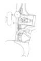
搭乗者センサ912は、搭乗者に関する情報を検出するセンサによって実現される。例えば、搭乗者センサ912は、車内に設けられたカメラ、マイク、環境センサを含んでいてもよい。また、搭乗者センサ912は、搭乗者の生体情報を検出する生体センサを含んでいてもよい。生体センサは、例えば座面又はステアリングホイール等に設けられ、座席に座った搭乗者又はステアリングを握るドライバーの生体情報を検出可能である。搭乗者センサ912は、例えば、図2に示す検出部110を形成し得る。The
なお、車外センサ908、車両状態センサ910、及び搭乗者センサ912といった各種センサは、それぞれ検出結果を示す情報を電子制御ユニット902へ出力する。これら各種センサは、電子制御ユニット902による制御に基づいて、センシング範囲又は精度等の設定を行ってもよい。また、これら各種センサは、例えば撮像された撮像画像に含まれる白線位置に基づいて、道路における自車両の走行位置を認識する処理等の、生データに基づく認識処理を行う認識モジュールを含んでいてもよい。The various sensors, such as the
通信IF914は、車両制御システム900による他の装置との通信を仲介する通信インタフェースである。通信IF914は、例えばV2X通信モジュールを含み得る。なお、V2X通信とは、車車間(Vehicle to Vehicle)通信及び路車間(Vehicle to Infrastructure)通信を含む概念である。他にも、通信IF914は、無線LAN(Local Area Network)、Wi-Fi(登録商標)、3G、LTE(Long Term Evolution)、Bluetooth(登録商標)、NFC(Near Field Communication)又はWUSB(Wireless USB)のための通信モジュールを含んでいてもよい。この通信IF914は、例えばインターネット又は車外の通信機器との間で、例えばTCP/IP等の所定のプロトコルに則して信号等を送受信することができる。通信IF914は、例えば、図2に示す通信部120を形成し得る。The communication IF 914 is a communication interface that mediates communication between the
出力装置916は、取得した情報を搭乗者に対して視覚的又は聴覚的に通知することが可能な装置で実現される。このような装置として、インストルメントパネル、ヘッドアップディスプレイ、プロジェクタ又はランプ等の表示装置や、スピーカ又はヘッドホン等の音声出力装置がある。具体的には、表示装置は、車両制御システム900が行った各種処理により得られた結果を、テキスト、イメージ、表、グラフ等、様々な形式で視覚的に表示する。その際、AR(Augmented Reality)オブジェクト等の仮想的なオブジェクトが表示されてもよい。他方、音声出力装置は、再生された音声データや音響データ等からなるオーディオ信号をアナログ信号に変換して聴覚的に出力する。上記表示装置及び上記音声出力装置は、例えば、図2に示す出力部130を形成し得る。The
動力生成装置918は、車両の駆動力を生成するための装置である。動力生成装置918は、例えば内燃機関により実現されてもよい。その場合、動力生成装置918は、電子制御ユニット902からの制御指令に基づいて、始動制御、停止制御、スロットルバルブの開度の制御、燃料噴射制御、又はEGR(Exhaust Gas Recirculation)制御等を行う。また、動力生成装置918は、例えばモータ、インバータ及びバッテリーにより実現されてもよい。その場合、動力生成装置918は、電子制御ユニット902からの制御指令に基づき、インバータを介してバッテリーからモータへ電力を供給し、正のトルクを出力させるモータ動作(いわゆる力行)と、モータにトルクを吸収させて発電し、インバータを介してバッテリーの充電を行う回生動作と、を行い得る。The
制動装置920は、車両に制動力を付与し、あるいは、車両を減速又は停止させるための装置である。制動装置920は、例えば各ホイールに設置されるブレーキ、及びブレーキペダルの踏圧力をブレーキに伝達するためのブレーキパイプ又は電気回路等を含み得る。また、制動装置920は、ABS(Antilock Brake System)又はESC(Electronic Stability Control)等のブレーキ制御による滑走又は横滑り防止機構を作動させるための制御装置を含んでいてもよい。
ステアリング922は、車両の進行方向(操舵角)を制御するための装置である。ステアリング922は、例えばステアリングホイール、ステアリングシャフト、ステアリングギア、及びタイロッド等を含み得る。また、ステアリング922は、ドライバーによる操舵を支援するためのパワーステアリングを含み得る。さらに、ステアリング922は、自動的な操舵を実現するためのモータ等の動力源を含み得る。The
ランプ作動装置924は、ヘッドライト、ウィンカー、車幅灯、フォグライト、又はストップランプ等の各種ランプの作動させる装置である。ランプ作動装置924は、例えばランプの明滅、光量、又は照射方向等を制御する。The
なお、動力生成装置918、制動装置920、ステアリング922、及びランプ作動装置924は、ドライバーによる手動操作に基づいて動作してもよいし、電子制御ユニット902による自動操作に基づいて動作してもよい。The
<5.2.情報処理装置の構成例>
図20は、本実施形態に係る情報処理装置のハードウェア構成の一例を示すブロック図である。なお、図20に示す情報処理装置1000は、例えば、図3に示したサーバ30を実現し得る。本実施形態に係るサーバ30による情報処理は、ソフトウェアと、以下に説明するハードウェアとの協働により実現される。 <5.2. Example of configuration of information processing device>
Fig. 20 is a block diagram showing an example of a hardware configuration of an information processing device according to this embodiment. The
図20に示すように、情報処理装置1000は、CPU(Central Processing Unit)1001、ROM(Read Only Memory)1002、RAM(Random Access Memory)1003及びホストバス1004aを備える。また、情報処理装置1000は、ブリッジ1004、外部バス1004b、インタフェース1005、入力装置1006、出力装置1007、ストレージ装置1008、ドライブ1009、接続ポート1011及び通信装置1013を備える。情報処理装置1000は、CPU1001に代えて、又はこれとともに、DSP若しくはASIC等の処理回路を有してもよい。As shown in FIG. 20, the
CPU1001は、演算処理装置および制御装置として機能し、各種プログラムに従って情報処理装置1000内の動作全般を制御する。また、CPU1001は、マイクロプロセッサであってもよい。ROM1002は、CPU1001が使用するプログラムや演算パラメータ等を記憶する。RAM1003は、CPU1001の実行において使用するプログラムや、その実行において適宜変化するパラメータ等を一時記憶する。CPU1001は、例えば、図3に示す制御部330を形成し得る。The
CPU1001、ROM1002及びRAM1003は、CPUバスなどを含むホストバス1004aにより相互に接続されている。ホストバス1004aは、ブリッジ1004を介して、PCI(Peripheral Component Interconnect/Interface)バスなどの外部バス1004bに接続されている。なお、必ずしもホストバス1004a、ブリッジ1004および外部バス1004bを分離構成する必要はなく、1つのバスにこれらの機能を実装してもよい。The
入力装置1006は、例えば、マウス、キーボード、タッチパネル、ボタン、マイクロフォン、スイッチ及びレバー等、ユーザによって情報が入力される装置によって実現される。また、入力装置1006は、例えば、赤外線やその他の電波を利用したリモートコントロール装置であってもよいし、情報処理装置1000の操作に対応した携帯電話やPDA等の外部接続機器であってもよい。さらに、入力装置1006は、例えば、上記の入力手段を用いてユーザにより入力された情報に基づいて入力信号を生成し、CPU1001に出力する入力制御回路などを含んでいてもよい。情報処理装置1000のユーザは、この入力装置1006を操作することにより、情報処理装置1000に対して各種のデータを入力したり処理動作を指示したりすることができる。The
出力装置1007は、取得した情報をユーザに対して視覚的又は聴覚的に通知することが可能な装置で形成される。このような装置として、CRTディスプレイ装置、液晶ディスプレイ装置、プラズマディスプレイ装置、ELディスプレイ装置、レーザープロジェクタ、LEDプロジェクタ及びランプ等の表示装置や、スピーカ及びヘッドホン等の音声出力装置や、プリンタ装置等がある。出力装置1007は、例えば、情報処理装置1000が行った各種処理により得られた結果を出力する。具体的には、表示装置は、情報処理装置1000が行った各種処理により得られた結果を、テキスト、イメージ、表、グラフ等、様々な形式で視覚的に表示する。他方、音声出力装置は、再生された音声データや音響データ等からなるオーディオ信号をアナログ信号に変換して聴覚的に出力する。The
ストレージ装置1008は、情報処理装置1000の記憶部の一例として形成されたデータ格納用の装置である。ストレージ装置1008は、例えば、HDD等の磁気記憶部デバイス、半導体記憶デバイス、光記憶デバイス又は光磁気記憶デバイス等により実現される。ストレージ装置1008は、記憶媒体、記憶媒体にデータを記録する記録装置、記憶媒体からデータを読み出す読出し装置および記憶媒体に記録されたデータを削除する削除装置などを含んでもよい。このストレージ装置1008は、CPU1001が実行するプログラムや各種データ及び外部から取得した各種のデータ等を格納する。ストレージ装置1008は、例えば、図3に示す学習データDB320を形成し得る。The
ドライブ1009は、記憶媒体用リーダライタであり、情報処理装置1000に内蔵、あるいは外付けされる。ドライブ1009は、装着されている磁気ディスク、光ディスク、光磁気ディスク、または半導体メモリ等のリムーバブル記憶媒体に記録されている情報を読み出して、RAM1003に出力する。また、ドライブ1009は、リムーバブル記憶媒体に情報を書き込むこともできる。The
接続ポート1011は、外部機器と接続されるインタフェースであって、例えばUSB(Universal Serial Bus)などによりデータ伝送可能な外部機器との接続口である。The
通信装置1013は、例えば、ネットワーク1020に接続するための通信デバイス等で形成された通信インタフェースである。通信装置1013は、例えば、有線若しくは無線LAN(Local Area Network)、LTE(Long Term Evolution)、Bluetooth(登録商標)又はWUSB(Wireless USB)用の通信カード等である。また、通信装置1013は、光通信用のルータ、ADSL(Asymmetric Digital Subscriber Line)用のルータ又は各種通信用のモデム等であってもよい。この通信装置1013は、例えば、インターネットや他の通信機器との間で、例えばTCP/IP等の所定のプロトコルに則して信号等を送受信することができる。通信装置1013は、例えば、図3に示す通信部310を形成し得る。The
なお、ネットワーク1020は、ネットワーク1020に接続されている装置から送信される情報の有線、または無線の伝送路である。例えば、ネットワーク1020は、インターネット、電話回線網、衛星通信網などの公衆回線網や、Ethernet(登録商標)を含む各種のLAN(Local Area Network)、WAN(Wide Area Network)などを含んでもよい。また、ネットワーク1020は、IP-VPN(Internet Protocol-Virtual Private Network)などの専用回線網を含んでもよい。The
<5.3.補足>
以上、本実施形態に係るセンサ装置100又はサーバ30の機能を実現可能なハードウェア構成の一例を示した。上記の各構成要素は、汎用的な部材を用いて実現されていてもよいし、各構成要素の機能に特化したハードウェアにより実現されていてもよい。従って、本実施形態を実施する時々の技術レベルに応じて、適宜、利用するハードウェア構成を変更することが可能である。 <5.3. Supplementary Information>
The above describes an example of a hardware configuration capable of implementing the functions of the
なお、上述のような本実施形態に係るセンサ装置100又はサーバ30の各機能を実現するためのコンピュータプログラムを作製し、ECU等に実装することが可能である。また、このようなコンピュータプログラムが格納された、コンピュータで読み取り可能な記録媒体も提供することができる。記録媒体は、例えば、磁気ディスク、光ディスク、光磁気ディスク、フラッシュメモリ等である。また、上記のコンピュータプログラムは、記録媒体を用いずに、例えばネットワークを介して配信されてもよい。It is possible to create a computer program for implementing each function of the
<<6.まとめ>>
以上、図1~図19を参照して、本開示の一実施形態について詳細に説明した。上記説明したように、本実施形態に係るセンサ装置100は、ユーザにより運転される車両の事故確率を予測し、予測した事故確率を上昇させた要因に応じた情報をユーザへ出力する。これにより、事故確率が高い場合に具体的にどのような事故回避行動を行うべきかが明確に提示されるので、ユーザは、容易に事故回避行動を行い、安全性を高めることができる。 <<6. Summary>>
An embodiment of the present disclosure has been described in detail above with reference to Figures 1 to 19. As described above, the
また、本実施形態に係るセンサ装置100は、事故の発生に影響を与え得る多様な特徴量ベクトルを用いて事故確率を予測する。例えば、センサ装置100は、ウィンカーの出し忘れ(車両操作情報)、集中力の低下(生体状態情報)、体調不良(生体情報)、窓の曇り(車内環境情報)、雨や夜(天候情報)、周りを見ていない(運転者物理状態情報)、片手でハンドルを切っている(運転者物理状態情報)、事故が起きやすい交差点(地図に紐付く事故情報)、運転が荒い(運転者のくせ情報)、乱暴な車が交差点の先にいる(近傍の他車両の運転習熟度情報又は事故確率)、等の事故の発生に影響を与え得る多様な特徴量ベクトルを用いて事故確率を予測する。これにより、事故確率の予測精度を向上させることができる。The
以上、添付図面を参照しながら本開示の好適な実施形態について詳細に説明したが、本開示の技術的範囲はかかる例に限定されない。本開示の技術分野における通常の知識を有する者であれば、請求の範囲に記載された技術的思想の範疇内において、各種の変更例または修正例に想到し得ることは明らかであり、これらについても、当然に本開示の技術的範囲に属するものと了解される。Although the preferred embodiment of the present disclosure has been described in detail above with reference to the attached drawings, the technical scope of the present disclosure is not limited to such examples. It is clear that a person with ordinary knowledge in the technical field of the present disclosure can conceive of various modified or revised examples within the scope of the technical ideas described in the claims, and it is understood that these also naturally fall within the technical scope of the present disclosure.
例えば、上記実施形態では、センサ装置100が車両に搭載される例を主に説明したが、本技術はかかる例に限定されない。例えば、センサ装置100は、航空機、自転車、自動二輪車等の任意の移動体に搭載可能である。また、センサ装置100は、スマートフォン又はHMD(Head Mounted Display)等のユーザデバイスとして実現されてもよい。また、センサ装置100は、信号機、監視カメラ、デジタルサイネージ、電光掲示板などの環境に設置される装置として実現されてもよい。その場合、センサ装置100は、例えば周囲を走行する車両の運転者への情報を出力する。For example, in the above embodiment, an example in which the
また、本明細書において説明した各装置は、単独の装置として実現されてもよく、一部または全部が別々の装置として実現されても良い。例えば、図2に示したセンサ装置100の機能構成例のうち、記憶部140及び制御部150が、検出部110、通信部120及び出力部130とネットワーク等で接続されたサーバ等の装置に備えられていても良い。Furthermore, each device described in this specification may be realized as a single device, or some or all of them may be realized as separate devices. For example, among the functional configuration example of the
また、本明細書においてフローチャート及びシーケンス図を用いて説明した処理は、必ずしも図示された順序で実行されなくてもよい。いくつかの処理ステップは、並列的に実行されてもよい。また、追加的な処理ステップが採用されてもよく、一部の処理ステップが省略されてもよい。In addition, the processes described in this specification using flowcharts and sequence diagrams do not necessarily have to be performed in the order shown. Some processing steps may be performed in parallel. Furthermore, additional processing steps may be employed, and some processing steps may be omitted.
また、本明細書に記載された効果は、あくまで説明的または例示的なものであって限定的ではない。つまり、本開示に係る技術は、上記の効果とともに、または上記の効果に代えて、本明細書の記載から当業者には明らかな他の効果を奏しうる。Furthermore, the effects described in this specification are merely descriptive or exemplary and are not limiting. In other words, the technology disclosed herein may achieve other effects that are apparent to a person skilled in the art from the description in this specification, in addition to or in place of the above effects.
なお、以下のような構成も本開示の技術的範囲に属する。
(1)
ユーザにより運転される車両の事故確率を予測する予測部と、
前記予測部により予測された前記事故確率を上昇させた要因に応じた情報を前記ユーザへ出力させる出力制御部と、
を備える情報処理装置。
(2)
前記出力制御部は、前記要因を示す情報を出力させる、前記(1)に記載の情報処理装置。
(3)
前記出力制御部は、ひとつ以上の前記要因から前記事故確率の上昇への寄与度に応じて選定した前記要因を示す情報を出力させる、前記(2)に記載の情報処理装置。
(4)
前記出力制御部は、前記事故確率を低下させるために前記ユーザが行うべき行動を指示する情報を出力させる、前記(1)~(3)のいずれか一項に記載の情報処理装置。
(5)
前記出力制御部は、前記事故確率を示す情報を出力させる、前記(1)~(4)のいずれか一項に記載の情報処理装置。
(6)
前記出力制御部は、前記事故確率を対数スケールで出力させる、前記(5)に記載の情報処理装置。
(7)
前記出力制御部は、前記事故確率の時系列推移を示す情報を出力させる、前記(5)又は(6)に記載の情報処理装置。
(8)
前記出力制御部は、前記事故確率の累積値に基づく情報を出力させる、前記(5)~(7)のいずれか一項に記載の情報処理装置。
(9)
前記出力制御部は、地図上に前記事故確率に関する情報を出力させる、前記(5)~(8)のいずれか一項に記載の情報処理装置。
(10)
前記予測部は、事故の予兆現象の発生確率を加味して学習された予測モデルを用いて前記事故確率を予測する、前記(1)~(9)のいずれか一項に記載の情報処理装置。
(11)
前記予兆現象は、急ブレーキ又は急ハンドルである、前記(10)に記載の情報処理装置。
(12)
前記予測部は、前記ユーザ又は前記車両に関する特徴量に基づいて前記事故確率を予測する、前記(1)~(11)のいずれか一項に記載の情報処理装置。
(13)
前記特徴量は、リアルタイムに検出される情報である、前記(12)に記載の情報処理装置。
(14)
前記特徴量は、蓄積又は登録された情報である、前記(12)に記載の情報処理装置。
(15)
前記予測部は、他の車両に関する特徴量に基づいて前記事故確率を予測する、前記(12)~(14)のいずれか一項に記載の情報処理装置。
(16)
ユーザにより運転される車両の事故確率を予測することと、
予測された前記事故確率を上昇させた要因に応じた情報を前記ユーザへ出力装置に出力させることと、
を含む情報処理方法。
(17)
コンピュータを、
ユーザにより運転される車両の事故確率を予測する予測部と、
前記予測部により予測された前記事故確率を上昇させた要因に応じた情報を前記ユーザへ出力させる出力制御部と、
として機能させるためのプログラム。 Note that the following configurations also fall within the technical scope of the present disclosure.
(1)
A prediction unit that predicts an accident probability of a vehicle driven by a user;
an output control unit that outputs information corresponding to a factor that has increased the accident probability predicted by the prediction unit to the user;
An information processing device comprising:
(2)
The information processing device according to (1), wherein the output control unit outputs information indicating the cause.
(3)
The information processing device according to (2), wherein the output control unit outputs information indicating a factor selected from one or more of the factors according to its contribution to an increase in the accident probability.
(4)
The information processing device according to any one of (1) to (3), wherein the output control unit outputs information instructing the user on an action to be taken to reduce the accident probability.
(5)
The information processing device according to any one of (1) to (4), wherein the output control unit outputs information indicating the accident probability.
(6)
The information processing device according to (5), wherein the output control unit outputs the accident probability on a logarithmic scale.
(7)
The information processing device according to (5) or (6), wherein the output control unit outputs information indicating a time series transition of the accident probability.
(8)
The information processing device according to any one of (5) to (7), wherein the output control unit outputs information based on a cumulative value of the accident probability.
(9)
The information processing device according to any one of (5) to (8), wherein the output control unit outputs information regarding the accident probability on a map.
(10)
The information processing device according to any one of (1) to (9), wherein the prediction unit predicts the accident probability using a prediction model that has been learned while taking into account the occurrence probability of a precursor phenomenon of an accident.
(11)
The information processing device according to (10), wherein the precursor phenomenon is sudden braking or sudden steering.
(12)
The information processing device according to any one of (1) to (11), wherein the prediction unit predicts the accident probability based on a feature amount related to the user or the vehicle.
(13)
The information processing device according to (12), wherein the feature amount is information detected in real time.
(14)
The information processing device according to (12), wherein the feature amount is accumulated or registered information.
(15)
The information processing device according to any one of (12) to (14), wherein the prediction unit predicts the accident probability based on features related to other vehicles.
(16)
Predicting an accident probability of a vehicle driven by a user;
outputting information corresponding to a factor that has increased the predicted accident probability to the user via an output device;
An information processing method comprising:
(17)
Computer,
A prediction unit that predicts an accident probability of a vehicle driven by a user;
an output control unit that outputs information corresponding to a factor that has increased the accident probability predicted by the prediction unit to the user;
A program to function as a
1 システム
100 センサ装置
110 検出部
120 通信部
130 出力部
140 記憶部
150 制御部
152 予測部
154 出力制御部
30 サーバ
310 通信部
320 学習データDB
330 制御部
332 記憶制御部
334 学習部
40 外部DB REFERENCE SIGNS
330
Claims (11)
Translated fromJapanese前記特徴量ベクトルを予測モデルに入力して得られる事故が発生しやすい場所に関する情報を取得する取得部と、
前記場所及び前記場所に対する警告の地図上への出力を制御する出力制御部と
を備える情報処理システム。 A generation unit that generates a feature vector based on sensor information related to a vehicle or a driver;
an acquisition unit that acquires information about locations where accidents are likely to occur, the information being obtained by inputting the feature vector into a prediction model;
and an output control unit that controls outputof the location and a warning for the location on a map .
請求項1に記載の情報処理システム。 The information processing system according to claim 1 , wherein the locations include locations where an accident probability is equal to or exceeds a threshold, or locations where an accident has occurred in the past.
請求項1又は2に記載の情報処理システム。 The information processing system according to claim 1 or 2, wherein the output control unit further controls output of routes with a low accident probability on the map.
請求項1乃至3のいずれかに記載の情報処理システム。 The information processing system according to claim 1 , wherein the output control unit further controls output of the current position of the vehicle on a map.
前記出力制御部は、前記要因ごとに予め定められた警告の出力を制御する
請求項1乃至4のいずれかに記載の情報処理システム。 The acquisition unit acquires information regarding factors that increase the accident probability,
The information processing system according to claim 1 , wherein the output control unit controls output of a predetermined warning for each of the causes.
請求項5に記載の情報処理システム。 The information processing system according to claim 5 , wherein the factor is a feature based on the sensor information, information estimated from the feature, or information estimated from a type of sensor.
請求項1乃至6のいずれかに記載の情報処理システム。 The information processing system according to claim 1 , wherein the feature vector includes at least one of a driving feature vector based on the sensor information detected in real time, and an attribute feature vector related to properties of the driver or the vehicle.
請求項1乃至7のいずれかに記載の情報処理システム。 The information processing system according to claim 1 , wherein the prediction model is trained using training data including the feature vector and accident information.
前記出力制御部は、地図上に前記予測情報を出力させる
請求項1乃至8のいずれかに記載の情報処理システム。 the acquisition unit acquires prediction information obtained by inputting the feature vector into the prediction model, the prediction information including information about the location;
The information processing system according to claim 1 , wherein the output control unit outputs the prediction information on a map.
車両又は運転者に関するセンサ情報に基づいて特徴量ベクトルを生成し、
前記特徴量ベクトルを予測モデルに入力して得られる事故が発生しやすい場所に関する情報を取得し、
前記場所及び前記場所に対する警告の地図上への出力を制御する
情報処理方法。 The information processing system
generating a feature vector based on sensor information relating to a vehicle or a driver;
Inputting the feature vector into a prediction model to obtain information about locations where accidents are likely to occur,
An information processing method for controlling output of said locationsand warnings for said locationson a map .
車両又は運転者に関するセンサ情報に基づいて特徴量ベクトルを生成し、
前記特徴量ベクトルを予測モデルに入力して得られる事故が発生しやすい場所に関する情報を取得し、
前記場所及び前記場所に対する警告の地図上への出力を制御する
処理を実行させるためのプログラム。 On the computer,
generating a feature vector based on sensor information relating to a vehicle or a driver;
Inputting the feature vector into a prediction model to obtain information about locations where accidents are likely to occur,
A program for executing a process for controlling outputof the locationand a warning for the location on a map.
Applications Claiming Priority (3)
| Application Number | Priority Date | Filing Date | Title |
|---|---|---|---|
| JP2015168527 | 2015-08-28 | ||
| JP2015168527 | 2015-08-28 | ||
| JP2020218555AJP7399075B2 (en) | 2015-08-28 | 2020-12-28 | Information processing device, information processing method and program |
Related Parent Applications (1)
| Application Number | Title | Priority Date | Filing Date |
|---|---|---|---|
| JP2020218555ADivisionJP7399075B2 (en) | 2015-08-28 | 2020-12-28 | Information processing device, information processing method and program |
Publications (2)
| Publication Number | Publication Date |
|---|---|
| JP2023168361A JP2023168361A (en) | 2023-11-24 |
| JP7638613B2true JP7638613B2 (en) | 2025-03-04 |
Family
ID=58188840
Family Applications (3)
| Application Number | Title | Priority Date | Filing Date |
|---|---|---|---|
| JP2017537581AActiveJP6819594B2 (en) | 2015-08-28 | 2016-05-20 | Information processing equipment, information processing methods and programs |
| JP2020218555AActiveJP7399075B2 (en) | 2015-08-28 | 2020-12-28 | Information processing device, information processing method and program |
| JP2023146703AActiveJP7638613B2 (en) | 2015-08-28 | 2023-09-11 | Information processing system, information processing method, and program |
Family Applications Before (2)
| Application Number | Title | Priority Date | Filing Date |
|---|---|---|---|
| JP2017537581AActiveJP6819594B2 (en) | 2015-08-28 | 2016-05-20 | Information processing equipment, information processing methods and programs |
| JP2020218555AActiveJP7399075B2 (en) | 2015-08-28 | 2020-12-28 | Information processing device, information processing method and program |
Country Status (5)
| Country | Link |
|---|---|
| US (2) | US11142195B2 (en) |
| EP (1) | EP3343535B1 (en) |
| JP (3) | JP6819594B2 (en) |
| CN (1) | CN107924633B (en) |
| WO (1) | WO2017038166A1 (en) |
Families Citing this family (30)
| Publication number | Priority date | Publication date | Assignee | Title |
|---|---|---|---|---|
| CN107924633B (en)* | 2015-08-28 | 2021-09-14 | 索尼公司 | Information processing apparatus, information processing method, and program |
| CA3028479A1 (en)* | 2017-04-18 | 2018-10-25 | Beijing Didi Infinity Technology And Development Co., Ltd. | System and method for determining safety score of driver |
| JP6524144B2 (en) | 2017-06-02 | 2019-06-05 | 本田技研工業株式会社 | Vehicle control system and method, and driving support server |
| JP6834860B2 (en)* | 2017-09-05 | 2021-02-24 | トヨタ自動車株式会社 | Collision prevention device, collision prevention method, collision prevention program, recording medium |
| JP6843270B2 (en)* | 2018-01-12 | 2021-03-17 | 三菱電機株式会社 | Accident risk calculation device, accident risk calculation method and accident risk calculation program |
| JP7453209B2 (en)* | 2018-07-30 | 2024-03-19 | アクセンチュア グローバル ソリューションズ リミテッド | Careless driving prediction system |
| US10890907B2 (en)* | 2018-12-14 | 2021-01-12 | Toyota Jidosha Kabushiki Kaisha | Vehicle component modification based on vehicular accident reconstruction data |
| JP7204525B2 (en)* | 2019-02-26 | 2023-01-16 | 株式会社東芝 | Traffic control device and traffic control method |
| WO2020188895A1 (en)* | 2019-03-18 | 2020-09-24 | 日本電気株式会社 | Edge computing server, control method, and non-transitory computer-readable medium |
| JP6796679B2 (en)* | 2019-04-26 | 2020-12-09 | 本田技研工業株式会社 | Vehicle control system and method, and driving support server |
| US12198402B2 (en)* | 2019-05-22 | 2025-01-14 | Nippon Telegraph And Telephone Corporation | Event occurrence time learning device, event occurrence time estimation device, event occurrence time learning method, event occurrence time estimation method, event occurrence time learning program, and event occurrence time estimation program |
| US11511737B2 (en) | 2019-05-23 | 2022-11-29 | Systomix, Inc. | Apparatus and method for processing vehicle signals to compute a behavioral hazard measure |
| US11999370B2 (en) | 2019-07-31 | 2024-06-04 | Nissan North America, Inc. | Automated vehicle system |
| JP2021050920A (en)* | 2019-09-20 | 2021-04-01 | 株式会社デンソー | Navigation system for electric vehicle |
| JP7293077B2 (en)* | 2019-10-02 | 2023-06-19 | 株式会社東芝 | Traffic control system and information provision method |
| KR102318801B1 (en)* | 2019-10-22 | 2021-10-28 | 한국통합민원센터 주식회사 | Driver traffic accident rate prediction system |
| GB2592217A (en)* | 2020-02-19 | 2021-08-25 | Daimler Ag | Method and system for providing adaptive display content on a display interface of a vehicle |
| US11475774B2 (en)* | 2020-04-03 | 2022-10-18 | Verizon Patent And Licensing Inc. | Systems and methods for machine learning based collision avoidance |
| CN113753056A (en)* | 2020-06-02 | 2021-12-07 | 汽车科睿特股份有限责任公司 | Driving event prediction device device and operation method thereof |
| CN115398509B (en)* | 2020-06-09 | 2025-01-03 | 罗集帝株式会社 | Operation support method, operation support system, and operation support server |
| JP7633013B2 (en)* | 2020-09-18 | 2025-02-19 | ロジスティード株式会社 | Safe driving support method, safe driving support system, and safe driving support server |
| JP7437241B2 (en)* | 2020-06-09 | 2024-02-22 | ロジスティード株式会社 | Operation support method, operation support system and operation support server |
| CN111861128B (en)* | 2020-06-20 | 2024-03-22 | 清华大学 | Method, system and storage medium for evaluating connection pipe comfort in man-machine cooperative control process of automatic driving vehicle |
| CN111859291B (en)* | 2020-06-23 | 2022-02-25 | 北京百度网讯科技有限公司 | Traffic accident identification method, device, equipment and computer storage medium |
| KR102370079B1 (en)* | 2020-09-01 | 2022-03-07 | 주식회사 인포카 | Driving support method and apparatus |
| US11518401B2 (en) | 2020-10-14 | 2022-12-06 | Magna Electronics Inc. | Vehicular driving assist with driver monitoring |
| CN112622812A (en)* | 2021-01-04 | 2021-04-09 | 北京汽车研究总院有限公司 | Control device and control method for automobile safety belt and vehicle |
| JP7735197B2 (en)* | 2022-01-28 | 2025-09-08 | 株式会社フジタ | Near miss prediction system, near miss prediction method, and information processing device |
| JP7729324B2 (en)* | 2022-12-22 | 2025-08-26 | トヨタ自動車株式会社 | Navigation system |
| WO2025169305A1 (en)* | 2024-02-06 | 2025-08-14 | 株式会社デンソーテン | Accident inference device, insurance fee examination device, on-vehicle equipment, terminal device, information processing system, accident inference method, accident inference program, ai model generation method, and ai generation program |
Citations (5)
| Publication number | Priority date | Publication date | Assignee | Title |
|---|---|---|---|---|
| JP2006277165A (en) | 2005-03-29 | 2006-10-12 | Osaka Gas Co Ltd | Traffic accident prediction system and car navigation device |
| WO2009128398A1 (en) | 2008-04-15 | 2009-10-22 | 日本電気株式会社 | Moving object warning device, moving object warning method, and moving object warning program |
| JP2009277059A (en) | 2008-05-15 | 2009-11-26 | Denso Corp | Apparatus for collecting and delivering risk information |
| JP2015099442A (en) | 2013-11-18 | 2015-05-28 | 富士通株式会社 | Vehicle warning device, vehicle warning method, vehicle warning program, and vehicle warning system |
| JP2021064395A (en) | 2015-08-28 | 2021-04-22 | ソニー株式会社 | Information processing device, information processing method, and program |
Family Cites Families (47)
| Publication number | Priority date | Publication date | Assignee | Title |
|---|---|---|---|---|
| US9102220B2 (en)* | 1992-05-05 | 2015-08-11 | American Vehicular Sciences Llc | Vehicular crash notification system |
| US5594414A (en)* | 1994-08-02 | 1997-01-14 | Namngani; Abdulatif | Collision probability detection system |
| US7426437B2 (en)* | 1997-10-22 | 2008-09-16 | Intelligent Technologies International, Inc. | Accident avoidance systems and methods |
| JPH11120478A (en) | 1997-10-17 | 1999-04-30 | Hitachi Ltd | Traffic accident management support system |
| JP4578795B2 (en)* | 2003-03-26 | 2010-11-10 | 富士通テン株式会社 | Vehicle control device, vehicle control method, and vehicle control program |
| JP4055656B2 (en)* | 2003-05-30 | 2008-03-05 | トヨタ自動車株式会社 | Collision prediction device |
| US20050125121A1 (en)* | 2003-11-28 | 2005-06-09 | Denso Corporation | Vehicle driving assisting apparatus |
| JP2005268847A (en)* | 2004-03-16 | 2005-09-29 | Olympus Corp | Image generating apparatus, image generating method, and image generating program |
| US20070016785A1 (en)* | 2005-07-14 | 2007-01-18 | Yannick Guay | System and method for digital signature and authentication |
| JP4396597B2 (en) | 2005-08-08 | 2010-01-13 | 株式会社デンソー | Dangerous reaction point recording system and driving support system |
| US7167799B1 (en)* | 2006-03-23 | 2007-01-23 | Toyota Technical Center Usa, Inc. | System and method of collision avoidance using intelligent navigation |
| JP4973331B2 (en)* | 2007-06-19 | 2012-07-11 | 株式会社デンソー | Information provision device |
| JP4450023B2 (en)* | 2007-07-12 | 2010-04-14 | トヨタ自動車株式会社 | Own vehicle risk acquisition device |
| JP5078637B2 (en)* | 2008-01-29 | 2012-11-21 | 富士通テン株式会社 | Radar apparatus and target detection method |
| EP2085279B1 (en)* | 2008-01-29 | 2011-05-25 | Ford Global Technologies, LLC | A system for collision course prediction |
| JP5077017B2 (en)* | 2008-03-28 | 2012-11-21 | 株式会社豊田中央研究所 | Driving support device and pedestrian detection device |
| JP2009282873A (en)* | 2008-05-26 | 2009-12-03 | Hitachi Ltd | Accident warning reporting system using bayesian network |
| US8041509B2 (en)* | 2008-08-19 | 2011-10-18 | Analytical Graphics, Inc. | System and method of addressing nonlinear relative motion for collision probability using parallelepipeds |
| DE102008049824B4 (en)* | 2008-10-01 | 2014-09-04 | Universität Kassel | Method for collision avoidance |
| JP2010152497A (en) | 2008-12-24 | 2010-07-08 | Toyota Motor Corp | Driving property acquisition device and traffic simulation system |
| JP2010198552A (en) | 2009-02-27 | 2010-09-09 | Konica Minolta Holdings Inc | Driving state monitoring device |
| JP4849148B2 (en)* | 2009-03-30 | 2012-01-11 | アイシン・エィ・ダブリュ株式会社 | Vehicle operation diagnosis device, vehicle operation diagnosis method, and computer program |
| JP2011100298A (en)* | 2009-11-06 | 2011-05-19 | Fujitsu Ten Ltd | Information processing device, on-vehicle device, information processing system, information processing method, and program |
| JP5446778B2 (en) | 2009-11-24 | 2014-03-19 | 富士通株式会社 | Accident occurrence prediction device, accident occurrence prediction program, and accident occurrence prediction method |
| JP2012006468A (en) | 2010-06-24 | 2012-01-12 | Clarion Co Ltd | Driving support control device |
| JP5189157B2 (en)* | 2010-11-30 | 2013-04-24 | 株式会社豊田中央研究所 | Moving object target state determination device and program |
| US8618952B2 (en)* | 2011-01-21 | 2013-12-31 | Honda Motor Co., Ltd. | Method of intersection identification for collision warning system |
| DE102011010864A1 (en)* | 2011-02-10 | 2011-12-08 | Daimler Ag | Method for predicting collision between lorry and e.g. pedestrian in dead angular area during driving on highway, involves computing collision probability between vehicle and object by intersecting vehicle and object accessibility amounts |
| US8698639B2 (en)* | 2011-02-18 | 2014-04-15 | Honda Motor Co., Ltd. | System and method for responding to driver behavior |
| JP5474254B2 (en)* | 2011-02-24 | 2014-04-16 | 三菱電機株式会社 | Navigation device, recommended speed calculation device, and recommended speed presentation device |
| JP5656732B2 (en)* | 2011-05-02 | 2015-01-21 | 株式会社デンソー | Collision probability computation device and collision probability computation program |
| US9123252B2 (en)* | 2011-08-10 | 2015-09-01 | Toyota Jidosha Kabushiki Kaisha | Drive assist apparatus |
| JP5966121B2 (en)* | 2011-10-03 | 2016-08-10 | 株式会社ユピテル | Driving support system and driving support program |
| US9241248B2 (en)* | 2012-02-29 | 2016-01-19 | Qualcomm Incorporated | Modified present signal mode for mobile device |
| JP5572657B2 (en)* | 2012-03-29 | 2014-08-13 | 富士重工業株式会社 | Vehicle driving support device |
| WO2013154169A1 (en)* | 2012-04-12 | 2013-10-17 | 日立建機株式会社 | Traffic management system for mobile body |
| EP2654028B1 (en)* | 2012-04-20 | 2018-09-26 | Honda Research Institute Europe GmbH | Orientation sensitive traffic collision warning system |
| US20130278441A1 (en)* | 2012-04-24 | 2013-10-24 | Zetta Research and Development, LLC - ForC Series | Vehicle proxying |
| US20140067800A1 (en)* | 2012-08-31 | 2014-03-06 | Amit Sharma | Systems and methods for analyzing and predicting automotive data |
| JPWO2014141330A1 (en)* | 2013-03-13 | 2017-02-16 | パナソニック株式会社 | Electronic devices |
| US9207095B2 (en) | 2013-03-15 | 2015-12-08 | Harman International Industries, Incorporated | Integrated navigation and collision avoidance systems |
| JP6022983B2 (en)* | 2013-03-29 | 2016-11-09 | 株式会社日本自動車部品総合研究所 | Driving assistance device |
| US9099006B2 (en)* | 2013-08-22 | 2015-08-04 | GM Global Technology Operations LLC | Context-aware threat response arbitration |
| CN104751678B (en)* | 2013-12-31 | 2017-09-15 | 中国移动通信集团公司 | A kind of method and apparatus being monitored to the traffic conflict that fault car triggers |
| JP6459220B2 (en)* | 2014-05-26 | 2019-01-30 | 株式会社リコー | Accident prevention system, accident prevention device, accident prevention method |
| KR20150144125A (en)* | 2014-06-16 | 2015-12-24 | 현대모비스 주식회사 | Safe driving guiding system and method thereof |
| US10621670B2 (en)* | 2014-08-15 | 2020-04-14 | Scope Technologies Holdings Limited | Determination and display of driving risk |
- 2016
- 2016-05-20CNCN201680047531.3Apatent/CN107924633B/enactiveActive
- 2016-05-20WOPCT/JP2016/065028patent/WO2017038166A1/ennot_activeCeased
- 2016-05-20USUS15/579,709patent/US11142195B2/enactiveActive
- 2016-05-20JPJP2017537581Apatent/JP6819594B2/enactiveActive
- 2016-05-20EPEP16841198.1Apatent/EP3343535B1/enactiveActive
- 2020
- 2020-12-28JPJP2020218555Apatent/JP7399075B2/enactiveActive
- 2021
- 2021-09-03USUS17/465,844patent/US11904852B2/enactiveActive
- 2023
- 2023-09-11JPJP2023146703Apatent/JP7638613B2/enactiveActive
Patent Citations (5)
| Publication number | Priority date | Publication date | Assignee | Title |
|---|---|---|---|---|
| JP2006277165A (en) | 2005-03-29 | 2006-10-12 | Osaka Gas Co Ltd | Traffic accident prediction system and car navigation device |
| WO2009128398A1 (en) | 2008-04-15 | 2009-10-22 | 日本電気株式会社 | Moving object warning device, moving object warning method, and moving object warning program |
| JP2009277059A (en) | 2008-05-15 | 2009-11-26 | Denso Corp | Apparatus for collecting and delivering risk information |
| JP2015099442A (en) | 2013-11-18 | 2015-05-28 | 富士通株式会社 | Vehicle warning device, vehicle warning method, vehicle warning program, and vehicle warning system |
| JP2021064395A (en) | 2015-08-28 | 2021-04-22 | ソニー株式会社 | Information processing device, information processing method, and program |
Also Published As
| Publication number | Publication date |
|---|---|
| CN107924633A (en) | 2018-04-17 |
| JPWO2017038166A1 (en) | 2018-06-14 |
| JP2023168361A (en) | 2023-11-24 |
| CN107924633B (en) | 2021-09-14 |
| US11904852B2 (en) | 2024-02-20 |
| JP6819594B2 (en) | 2021-01-27 |
| EP3343535A4 (en) | 2019-08-21 |
| JP7399075B2 (en) | 2023-12-15 |
| JP2021064395A (en) | 2021-04-22 |
| WO2017038166A1 (en) | 2017-03-09 |
| EP3343535B1 (en) | 2025-04-02 |
| US11142195B2 (en) | 2021-10-12 |
| US20210394751A1 (en) | 2021-12-23 |
| EP3343535A1 (en) | 2018-07-04 |
| US20180170372A1 (en) | 2018-06-21 |
Similar Documents
| Publication | Publication Date | Title |
|---|---|---|
| JP7638613B2 (en) | Information processing system, information processing method, and program | |
| US10699569B2 (en) | Information processing apparatus, information processing method, and program | |
| US11295143B2 (en) | Information processing apparatus, information processing method, and program | |
| US20240109542A1 (en) | Exhaustive Driving Analytical Systems and Modelers | |
| JP7263233B2 (en) | Method, system and program for detecting vehicle collision | |
| JP2021185486A (en) | System and method for supporting operation to safely catch up with vehicle | |
| JP2024538536A (en) | VEHICLE AND MOBILE DEVICE INTERFACE FOR VEHICLE OCCUPANT ASSISTANCE - Patent application | |
| CN118119523A (en) | Vehicle and mobile device interfaces for vehicle occupant assistance | |
| US10336252B2 (en) | Long term driving danger prediction system | |
| CN108538086A (en) | Driver is assisted to carry out road track change | |
| JP2017174355A (en) | Drive support method and drive support device using the same, automatic drive controller, vehicle, drive support system, and program | |
| US11926259B1 (en) | Alert modality selection for alerting a driver | |
| CN112789205A (en) | Detecting and responding to queues for autonomous vehicles | |
| JP7390329B2 (en) | Recognition index setting device | |
| JP7582338B2 (en) | In-vehicle device, processing method and program | |
| US20250191015A1 (en) | Vehicle | |
| WO2024252912A1 (en) | Information processing device, information processing method, and information processing system | |
| WO2024043053A1 (en) | Information processing device, information processing method, and program |
Legal Events
| Date | Code | Title | Description |
|---|---|---|---|
| A521 | Request for written amendment filed | Free format text:JAPANESE INTERMEDIATE CODE: A523 Effective date:20231011 | |
| A621 | Written request for application examination | Free format text:JAPANESE INTERMEDIATE CODE: A621 Effective date:20231011 | |
| A871 | Explanation of circumstances concerning accelerated examination | Free format text:JAPANESE INTERMEDIATE CODE: A871 Effective date:20231011 | |
| A131 | Notification of reasons for refusal | Free format text:JAPANESE INTERMEDIATE CODE: A131 Effective date:20240116 | |
| A521 | Request for written amendment filed | Free format text:JAPANESE INTERMEDIATE CODE: A523 Effective date:20240305 | |
| A02 | Decision of refusal | Free format text:JAPANESE INTERMEDIATE CODE: A02 Effective date:20240507 | |
| A521 | Request for written amendment filed | Free format text:JAPANESE INTERMEDIATE CODE: A523 Effective date:20240702 | |
| A911 | Transfer to examiner for re-examination before appeal (zenchi) | Free format text:JAPANESE INTERMEDIATE CODE: A911 Effective date:20240709 | |
| A912 | Re-examination (zenchi) completed and case transferred to appeal board | Free format text:JAPANESE INTERMEDIATE CODE: A912 Effective date:20240802 | |
| A61 | First payment of annual fees (during grant procedure) | Free format text:JAPANESE INTERMEDIATE CODE: A61 Effective date:20250218 | |
| R150 | Certificate of patent or registration of utility model | Ref document number:7638613 Country of ref document:JP Free format text:JAPANESE INTERMEDIATE CODE: R150 |