JP7637758B1 - Input devices - Google Patents
Input devicesDownload PDFInfo
- Publication number
- JP7637758B1 JP7637758B1JP2023221552AJP2023221552AJP7637758B1JP 7637758 B1JP7637758 B1JP 7637758B1JP 2023221552 AJP2023221552 AJP 2023221552AJP 2023221552 AJP2023221552 AJP 2023221552AJP 7637758 B1JP7637758 B1JP 7637758B1
- Authority
- JP
- Japan
- Prior art keywords
- housing
- sound
- vibration
- drive signal
- input device
- Prior art date
- Legal status (The legal status is an assumption and is not a legal conclusion. Google has not performed a legal analysis and makes no representation as to the accuracy of the status listed.)
- Active
Links
Images


Landscapes
- Position Input By Displaying (AREA)
Abstract
Translated fromJapanese
Description
Translated fromJapanese本発明は、ペン型の入力デバイス、及び該入力デバイスと情報処理装置とを備える情報処理システムに関する。The present invention relates to a pen-type input device and an information processing system including the input device and an information processing device.
ノート型PC、タブレット型PC及びスマートフォン等の情報処理装置は、タッチスクリーンに対する入力操作にペン型の入力デバイスが用いられることがある。例えば特許文献1には、タッチパネルに対する入力に使用するタッチペンにおいて、棒状の筐体の内部に振動発生装置を設けた構成が開示されている。Information processing devices such as notebook PCs, tablet PCs, and smartphones may use a pen-type input device for input operations on a touch screen. For example, Patent Document 1 discloses a configuration in which a vibration generating device is provided inside a rod-shaped housing of a touch pen used for inputting to a touch panel.
上記のような振動発生装置を備えた入力デバイスは、ハプティックペン(haptic pen)とも呼ばれ、触覚フィードバック機能を有する。触覚フィードバックは、文字等を表示するタッチスクリーンへの接触に応じて振動を発生させ、使用感を向上させるためのものである。An input device equipped with a vibration generating device as described above is also called a haptic pen, and has a tactile feedback function. Haptic feedback generates vibrations in response to contact with a touch screen that displays characters, etc., in order to improve the user experience.
ところで、鉛筆やボールペンのような一般的な筆記具は、触覚で知覚できる振動以外にも、筆記時に発生する音(筆記音)も使用感の向上に寄与している。しかしながら従来の入力デバイスは、このような筆記音については考慮されていない。Incidentally, in addition to the vibrations that can be perceived by the touch, common writing implements such as pencils and ballpoint pens also produce sounds (writing sounds) that contribute to improving the user experience. However, conventional input devices do not take such writing sounds into consideration.
本発明は、上記従来技術の課題を考慮してなされたものであり、使用感を向上することができる入力デバイス及び情報処理システムを提供することを目的とする。The present invention was made in consideration of the problems with the conventional technology described above, and aims to provide an input device and information processing system that can improve usability.
本発明の第1態様に係る入力デバイスは、ペン型の入力デバイスであって、細長い棒状に形成された筐体と、前記筐体の先端に設けられたペン先部と、前記筐体内で該筐体の長手方向での中央よりも前記ペン先部に近い位置に配置され、振動成分と音成分を合成した駆動信号が入力されると共に、該駆動信号に従った振動を発生する振動発生部と、前記振動発生部から離れた位置に設けられ、前記振動発生部が発生した前記音成分の駆動信号に従った音振動が振動伝達媒体を介して伝達されると共に、該音振動を前記筐体の外部に出力する音出力部と、を備える。The input device according to the first aspect of the present invention is a pen-type input device, and includes a housing formed in a long, thin rod shape, a pen tip portion provided at the tip of the housing, a vibration generating portion disposed within the housing at a position closer to the pen tip portion than the center of the housing in the longitudinal direction, receiving a drive signal that combines a vibration component and a sound component, and generating vibrations in accordance with the drive signal, and a sound output portion disposed at a position away from the vibration generating portion, transmitting sound vibrations in accordance with the drive signal of the sound component generated by the vibration generating portion via a vibration transmission medium, and outputting the sound vibrations to the outside of the housing.
前記音出力部は、前記筐体の長手方向での中央よりも前記ペン先部とは反対側のペン尻部に近い位置に配置されていてもよい。The sound output unit may be positioned closer to the end of the pen, on the opposite side to the tip, than to the center of the housing in the longitudinal direction.
前記音出力部は、前記筐体の外壁に貫通形成された孔部を有してもよい。The sound output unit may have a hole formed through the outer wall of the housing.
前記音出力部は、前記孔部に連通し、前記音振動を増大させる空洞空間を有してもよい。The sound output section may have a hollow space that communicates with the hole and amplifies the sound vibrations.
前記筐体に設けられた開口部の一部を塞ぐように前記筐体に支持されたボタンスイッチを備え、前記孔部は、前記ボタンスイッチと前記筐体との間に形成された隙間であってもよい。The device may include a button switch supported on the housing so as to cover a portion of an opening in the housing, and the hole may be a gap formed between the button switch and the housing.
前記筐体内には、該筐体の長手方向に沿って延在し、前記振動発生部と前記音出力部との間を接続する連通経路が形成され、前記振動伝達媒体は、前記連通経路内の空気を含むものでもよい。A communication path is formed within the housing, extending along the longitudinal direction of the housing and connecting the vibration generating unit and the sound output unit, and the vibration transmission medium may include air within the communication path.
前記音出力部は、前記筐体の内部に設けられ、前記振動伝達媒体を介して伝達された音振動を増大させる空洞空間と、前記筐体の外壁に形成された開口部を塞ぐように設けられ、前記空洞空間の一面を形成する振動板と、を有してもよい。The sound output unit may have a hollow space provided inside the housing that amplifies the sound vibrations transmitted through the vibration transmission medium, and a diaphragm that is provided to close an opening formed in the outer wall of the housing and forms one side of the hollow space.
前記音出力部は、前記筐体の外壁に取り付けられた金属製のペンクリップを有し、
前記振動伝達媒体は、前記筐体の長手方向に沿って延在し、前記振動発生部と前記ペンクリップとの間を接続する金属棒体を含むものでもよい。 the sound output unit has a metal pen clip attached to an outer wall of the housing,
The vibration transmission medium may include a metal rod extending along the longitudinal direction of the housing and connecting between the vibration generating unit and the pen clip.
前記筐体に対して着脱可能に装着されたキャップ状部材を備え、前記音出力部は、前記キャップ状部材に設けられ、前記音振動を増大させる空洞空間と、前記キャップ状部材の外壁に貫通形成され、前記空洞空間と連通する孔部と、を有してもよい。The device may include a cap-shaped member that is removably attached to the housing, and the sound output unit may have a hollow space provided in the cap-shaped member that amplifies the sound vibrations, and a hole formed through an outer wall of the cap-shaped member and communicating with the hollow space.
前記振動伝達媒体は、前記筐体の長手方向に沿って延在し、前記振動発生部と前記音出力部との間を接続する金属棒体を含むものでもよい。The vibration transmission medium may include a metal rod extending along the longitudinal direction of the housing and connecting the vibration generating unit and the sound output unit.
本発明の第2態様に係る情報処理システムは、情報処理装置と、ペン型の入力デバイスとを備える情報処理システムであって、前記入力デバイスは、細長い棒状に形成された筐体と、前記筐体の先端に設けられたペン先部と、前記筐体内で該筐体の長手方向での中央よりも前記ペン先部に近い位置に配置され、振動成分と音成分を合成した駆動信号が入力されると共に、該駆動信号に従った振動を発生する振動発生部と、前記振動発生部から離れた位置に設けられ、前記振動発生部が発生した前記音成分の駆動信号に従った音振動が伝達されると共に、該音振動を前記筐体の外部に出力する音出力部と、を備える。The information processing system according to the second aspect of the present invention is an information processing system including an information processing device and a pen-type input device, the input device including a housing formed in a long and thin rod shape, a pen tip portion provided at the tip of the housing, a vibration generating portion disposed within the housing at a position closer to the pen tip portion than the center of the housing in the longitudinal direction, receiving a drive signal that combines a vibration component and a sound component, and generating vibrations according to the drive signal, and a sound output portion disposed at a position away from the vibration generating portion, transmitting sound vibrations according to the drive signal of the sound component generated by the vibration generating portion, and outputting the sound vibrations to the outside of the housing.
本発明の上記態様によれば、使用感を向上することができる。The above aspects of the present invention can improve the feel of use.
以下、本発明に係る入力デバイス及び情報処理システムついての好適な実施形態を挙げ、添付の図面を参照しながら詳細に説明する。Below, preferred embodiments of the input device and information processing system according to the present invention will be described in detail with reference to the attached drawings.
図1は、一実施形態に係る入力デバイス10を備える情報処理システム12の構成例を模式的に示す斜視図である。入力デバイス10は、情報処理装置14の入力操作に使用するペン型の入力デバイスである。入力デバイス10は、デジタルペン、スタイラス、電子ペン、又はスマートペン等とも呼ばれる。本実施形態では、情報処理装置14としてタブレット端末を例示する。入力デバイス10の使用対象となる情報処理装置は、タブレット端末以外、例えばノート型PCやスマートフォン等でもよい。FIG. 1 is a perspective view that shows a schematic configuration example of an
情報処理装置14は、薄く扁平な平板形状を有する装置筐体16と、装置筐体16の一面を覆うタッチスクリーン18とを備える。装置筐体16の内部には、CPU等の処理装置を実装したマザーボード及びバッテリ装置等の各種の電子部品が搭載されている。The
タッチスクリーン18は、表示部18aと、タッチセンサ18bとを備える。表示部18aは、液晶や有機EL等で形成され、各種情報を表示可能である。タッチセンサ18bは、表示部18aの表面に重ねて配置される。タッチセンサ18bは、タッチスクリーン18の表面18cに対する入力デバイス10の入力動作を検出可能なタッチパネルである。情報処理装置14は、入力動作の有無を監視し、入力動作を検出した位置を特定し、入力動作に基づくデータ入力又は編集を実行することができる。情報処理装置14は、例えばタッチセンサ18bに入力デバイス10が接触した接触位置の軌跡を表示部18aに表示させる。The
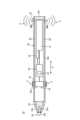
図2は、第1実施形態に係る入力デバイス10の内部構造を模式的に示す断面図である。Figure 2 is a cross-sectional view that shows a schematic internal structure of the
入力デバイス10は、使用者が把持し、タッチスクリーン18の表面18cに接触しながら移動させることで、文字、記号及び図形等のデータ入力や編集に用いることができる。The
図2に示すように、入力デバイス10は、筐体20と、ペン先部22と、振動発生部24と、音出力部26と、連通経路27と、回路基板28と、無線通信部30と、バッテリ装置31とを備える。図2において、回路基板28と、振動発生部24及びバッテリ装置31等との間を繋ぐ太線は配線を示し、図4~図8においても同様である。As shown in FIG. 2, the
筐体20は、樹脂、金属、又は木材属等で形成された細長い棒状の筒体である。筐体20は、真円若しくは楕円の円筒状、又は角筒状等の各種断面形状を採用できる。筐体20は、鉛筆やボールペン等の筆記具と同様、人手で把持するのに適した長さ及び太さを有する。The
ペン先部22は、タッチスクリーン18に対する入力部である。ペン先部22は、筐体20の先端部20aから突出するように設けられる。先端部20aは、先細りのテーパ形状を有し、例えば円錐台形状である。ペン先部22は、先端部20aの中心から筐体20の軸方向Aに沿って突出している。軸方向Aは、細長い棒状の筐体20の長手方向に延びる方向である。ペン先部22は、細い棒状の基端部22aが筐体20内でホルダ32に支持され、円錐状のペン先22bが筐体20外に露出している。ホルダ32は、筐体20の内部における先端付近で支持されている。ペン先部22は、ホルダ32に対して着脱可能に又は着脱不能に支持される。The
振動発生部24は、情報処理装置14から回路基板28を経た駆動信号に従って振動する。振動発生部24は、例えばブラケット34を介して筐体20の内周面に支持されている。振動発生部24は、例えばリニア共振アクチュエータ(LRA:Linear Resonant Actuator)で構成され、往復振動するアクチュエータ24aを備える(図3も参照)。振動発生部24は、アクチュエータ24aの振動方向が軸方向Aに沿うように配置することができる。この場合、振動発生部24は筐体20内で軸方向Aに沿った振動を発生する。振動発生部24は、アクチュエータ24aの振動方向が軸方向Aと直交するように配置することもできる。この場合、振動発生部24は筐体20内で軸方向Aと直交する方向の振動を発生する。The vibration generating
ブラケット34は、例えば樹脂又は金属で形成された塊状の部材である。ブラケット34は、例えば振動発生部24と筐体20の内周面との間に介在する筒状部材や柱状部材である。ブラケット34は、振動発生部24の側面を振動が逃げないように強固に覆うことができる。ブラケット34は、後述する振動発生部24の振動成分に従った振動を筐体20及び筐体20を保持する指に伝達する。ブラケット34は、例えば図7及び図8に示す入力デバイス60,70では、振動発生部24をフローティング支持可能なゴム材等で形成することも有効である。ブラケット34は省略してもよい。この場合、振動発生部24は筐体20の内壁に対してねじ又は接着剤等で直接的に固定するとよい。The
音出力部26は、振動発生部24が発生する音振動を筐体20の外部に出力する部分である。音出力部26は振動発生部24から離れた位置に設けられている。本実施形態の音出力部26は、筐体20の外壁20bに貫通形成された孔部26aで構成されている。音出力部26は筐体20の長手方向の中央よりもペン尻部20cに近い位置に配置されることができる。本実施形態の孔部26aは、筐体20のペン尻部20cの近傍で筐体20の側面に開口している。ペン尻部20cは、筐体20の長手方向でペン先部22(先端部20a)側とは反対側の基端部である。孔部26aは外壁20bの側面に形成された微細な孔部である。孔部26aは、1個でもよいし、外壁20bの周方向に沿って複数個形成されてもよい。The
連通経路27は、筐体20内でその長手方向(A方向)に沿って延在する空間である。連通経路27は振動発生部24と音出力部26との間を接続する空気通路である。図2に示す連通経路27は孔部26aから振動発生部24まで連通する細長い空間である。筐体20の内部には、振動発生部24、回路基板28、無線通信部30、及びバッテリ装置31等の電子部品と、各種の構造部品が収容されている。連通経路27は、これら電子部品及び構造部品を避けつつ軸方向Aに沿って延在する。The
回路基板28は、筐体20内で支持されている。回路基板28は、入力デバイス10の制御基板であり、例えばMCU(Micro Controller Unit)38を実装している。MCU38は、入力デバイス10の機能を統括的に制御する処理装置である。MCU38は、プロセッサと、ROMやRAM等のメモリと、各種の入出力インタフェースを備える。MCU38は、情報処理装置14とは独立に稼働する。無線通信部30は、情報処理装置14の無線通信部46(図3参照)と無線データを送受信するための無線通信モジュールである。バッテリ装置31は、入力デバイス10の電源である。バッテリ装置31は、乾電池でもよいし、充電池でもよい。The
次に、情報処理システム12の機能構成の一例について説明する。Next, an example of the functional configuration of the
図3は、一実施形態に係る情報処理システム12の機能構成例を示すブロック図である。図3に示すように、情報処理システム12は、情報処理装置14と、入力デバイス10とを備える。FIG. 3 is a block diagram showing an example of the functional configuration of an
情報処理装置14は、タッチスクリーン18と、制御部40と、タッチ・ペンモジュール42と、描画アプリ44と、無線通信部46とを備える。タッチスクリーン18は、上記したように表示部18a及びタッチセンサ18bを有する。The
制御部40は、情報処理装置14の機能を統括的に制御する。制御部40は、例えばCPU等の処理装置にプログラムを実行させること、すなわち、ソフトウェアにより実現してもよいし、IC(Integrated Circuit)等のハードウェアにより実現してもよいし、ソフトウェア及びハードウェアを併用して実現してもよい。本実施形態の制御部40は、OS(Operating System)等のソフトウェアとCPU等の処理装置とを含む。The
タッチ・ペンモジュール42は、制御部40と連係し、タッチスクリーン18及び入力デバイス10を制御する。タッチ・ペンモジュール42は、例えばCPU等を実装したマザーボードに接続されたサブカードとして構成されてもよい。描画アプリ44は、タッチ・ペンモジュール42を介してタッチスクリーン18や入力デバイス10を制御するアプリケーションソフトウェアである。無線通信部46は、入力デバイス10の無線通信部30と無線データを送受信するための無線通信モジュールである。The
入力デバイス10は、MCU38と、無線通信部30と、振動発生部24とを備える。The
MCU38は、情報処理装置14から無線通信部30を用いて振動制御情報及び音制御情報が入力される。音制御情報及び振動制御情報は、例えばタッチ・ペンモジュール42が制御部40とも連係し、入力デバイス10のタッチスクリーン18に対する入力動作時の振動周波数等を制御し、同時にこの振動によって発生する音(筆記音)の大きさや周波数等を制御するための情報である。MCU38は、これら制御情報を用いて、振動成分と音成分を合成した駆動信号を生成する。MCU38は、生成した駆動信号を振動発生部24に出力する。Vibration control information and sound control information are input to the
振動発生部24は、アクチュエータ24aと、DAC24bと、アンプ24cとを備える。DAC(Digital-to-Analog Converter)24bは、MCU38から入力されるデジタルの駆動信号をアナログの駆動信号に変換する。DAC24bは、変換されたアナログの駆動信号をアンプ24cに出力する。アンプ(amplifier)24cは、DAC24bから入力される駆動信号の振幅を調整し、振幅を調整した駆動信号をアクチュエータ24aに出力する。アクチュエータ24aは、アンプ24cから入力される駆動信号のうち、振動成分に従った振動を発生する振動発生源であり、音成分に従った音振動を発生する音発生源でもある。The
次に、入力デバイス10による入力動作及びその作用効果について説明する。Next, we will explain the input operation using the
図1に示すように、入力デバイス10の入力動作は、ペン先22bをタッチスクリーン18の表面18cに接触させて移動させる。そうすると、入力デバイス10は、タッチ・ペンモジュール42から描画アプリ44及び制御部40を経た制御情報を受信する。入力デバイス10は、この制御信号に基づきMCU38の制御下に振動発生部24に振動成分と音成分を合成した駆動信号を入力し、アクチュエータ24aを駆動して振動を発生させる。As shown in FIG. 1, the input operation of the
図2に示すように、振動発生部24は、振動成分の駆動信号に従った振動(振動H)を発生する。この振動Hは、筐体20を保持する指で触覚として感知することができる。従って使用者は入力デバイス10の筆記に伴う振動Hを指先で受けることができ、高い使用感が得られる。振動Hの共振周波数は、例えば人間が感じやすい周波数である150~300Hz程度とすることができる。As shown in FIG. 2, the
さらに振動発生部24は、音成分の駆動信号に従った音振動(音S)を発生する。この音Sは、連通経路27内の空気を振動伝達媒体として音出力部26まで伝達され、孔部26aから筐体20の外部へと効率よく出力される。図2中に1点鎖線で示す矢印は、音信号の伝達を模式的に示しており、図4以降の各図においても同様である。従って使用者は入力デバイス10の筆記に伴う音Sを聴覚で感知でき、一層高い使用感が得られる。音Sの共振周波数は、例えば人間の可聴帯域のうち、高い感度が得られる500Hz~2kHz程度とすることができる。The
以上のように、本実施形態の入力デバイス10は、細長い棒状に形成された筐体220と、筐体20の先端に設けられたペン先部22と、筐体20内でその長手方向での中央よりもペン先部22に近い位置に配置された振動発生部24と、振動発生部24から離れた位置に設けられた音出力部26とを備える。振動発生部24は、振動成分と音成分を合成した駆動信号が入力されると共に、該駆動信号に従った振動を発生する。音出力部26は、振動発生部24が発生した音成分の駆動信号に従った音振動が振動伝達媒体を介して伝達され、この音振動を筐体20の外部に出力する。As described above, the
従って、入力デバイス10は、使用者に対して触覚による振動Hと、聴覚による音Sとを出力しながらの入力動作が可能であり、鉛筆やボールペン等の筆記具と類似した高い使用感が得られる。しかも入力デバイス10は振動H及び音Sを筐体20内に搭載した共通の振動発生部24で発生させることができる。このため入力デバイス10は、消費電力を抑えつつ、構成の簡素化と部品点数削減によるコスト低減も可能となる。The
特に振動発生部24は、十分な触覚振動を出力できるアクチュエータ24aを用いた場合でも大きな音を出すことは難しい。すなわち、アクチュエータで振動を出力する場合、アクチュエータの特性が触覚振動領域の周波数200~300Hzに共振周波数がある。このため、触覚振動と共に音を出そうとする場合、音の周波数帯域の周波数もアクチュエータに入力すればと同時に音も出るが、十分に大きな音を出すことは難しい。この点、当該入力デバイス10は、アクチュエータ24aが発生する音振動を筐体20の外部に出力するための音出力部26(孔部26a)を有するため、大きな音Sを出力することが可能となっている。In particular, it is difficult for the
一方で、入力デバイス10の筆記音は、例えば情報処理装置14のスピーカーから発生させる構成も考え得る。ところが、この場合はスピーカーによって十分な音量は出せるが、音の発生位置及び振動との同期を得ることは難しく、使用者に違和感を与える。この点、本実施形態の入力デバイス10は、音Sが入力デバイス10自体から発生するため、音の発生位置が筆記位置と同期する。さらに入力デバイス10は、音Sと振動も同期するため、違和感のない高い使用感が得られるという利点がある。特に音出力部26は、ペン尻部20cに近い位置にあり、入力デバイス10のうちで使用者の耳に最も近い位置にあると言える。このため、音Sの音量が小さい場合であっても使用者の聴覚で感知し易いという利点がある。On the other hand, it is also conceivable that the writing sound of the
入力デバイス10の音出力部26は、筐体20の外壁20bに形成した孔部26aによって構成されている。このため音出力部26は簡素な構成でありながらも、筐体20内で発生した振動発生部24からの音Sを効率的に筐体20外へと出力できる。なお、入力デバイス10の筐体20は孔部26aが貫通形成されている。そこで入力デバイス10は、筐体20内に収容された回路基板28等の電子部品や各接続端子等に防水コーティング等による防水処理を設けることもできる。The
図4は、図2に示す入力デバイス10の変形例に係る入力デバイス10Aの断面図である。図4において、図1~図3に示される参照符号と同一の参照符号は同一又は同様な構成を示し、このため同一又は同様な機能及び効果を奏するものとして詳細な説明を省略し、図5においても同様とする。Figure 4 is a cross-sectional view of an
図4に示す入力デバイス10Aは、図2に示す入力デバイス10と比べて、音出力部26とは構成の異なる音出力部26Aを備える。音出力部26Aは、孔部26aと共に空洞空間26bを有する。The
空洞空間26bは筐体20の内部に形成された空洞である。空洞空間26bは、例えば連通経路27の断面積よりも大きな断面積を有する。空洞空間26bは、例えばペン尻部20cとバッテリ装置31との間に設けられる。図4に示す構成例の空洞空間26bは、筐体20の基端開口を閉じる蓋体(ペン尻部20c)と、バッテリ装置31の後方に設けた立壁20dとの間に形成されている。立壁20dは、例えば筐体20の外壁20bを形成する壁部と一体的に形成され、筐体20の内部空間を軸方向Aに仕切る節状部材である。立壁20dは一部に連通経路27が貫通し、これにより連通経路27と空洞空間26bとを連通させている。立壁20dは省略してもよい。この場合、空洞空間26bは、筐体20内に収容される部品、例えばバッテリ装置31を立壁20dの代わりに用いてもよい。The
空洞空間26bはスピーカーのエンクロージャーの内部空間に相当する。空洞空間26bは、連通経路27を介して伝達された振動発生部24からの音振動(音S)を増大させる空間である。音出力部26Aは、空洞空間26bで増大させた音Sを孔部26aから筐体20の外部へと効率よく出力することができる。従って、入力デバイス10Aは、使用者に対して大きな筆記音を出力することができる。The
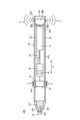
図5は、図2に示す入力デバイス10の別の変形例に係る入力デバイス10Bの断面図である。Figure 5 is a cross-sectional view of an
図5に示す入力デバイス10Bは、図2に示す入力デバイス10と比べて、音出力部26とは構成の異なる音出力部26Bを備える。The
入力デバイス10Bの筐体20は、外壁20bに形成された開口部20eにボタンスイッチ48が設けられている。開口部20eは、例えば筐体20のペン尻部20cに形成された円筒状の開口である。ボタンスイッチ48は開口部20eの大部分を塞ぐように配置され、軸方向Aに沿って進退可能な押しボタンである。ボタンスイッチ48は、例えば入力デバイス10Bの電源のオンオフに用いることができる。ボタンスイッチ48と開口部20eの内周面との間には、ボタンスイッチ48の進退用の隙間(クリアランス)が形成されている。この隙間が、音出力部26の孔部26aに代わる音出力部26Bの孔部26cとして機能する。The
従って、入力デバイス10Bにおいても使用者に対して筆記音(音S)を孔部26cから効率よく出力することができる。入力デバイス10Bの孔部26cはボタンスイッチ48の進退動作に必要な隙間を利用したものである。このため入力デバイス10Bは、筐体20の外壁20bに孔部26aを形成する必要がなく、外観品質が向上する。Therefore, the
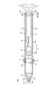
図6は、第2実施形態に係る入力デバイス50の内部構造を模式的に示す断面図である。図6において、図1~図5に示される参照符号と同一の参照符号は同一又は同様な構成を示し、このため同一又は同様な機能及び効果を奏するものとして詳細な説明を省略し、図7及び図8においても同様とする。Figure 6 is a cross-sectional view showing a schematic internal structure of an
図6に示す入力デバイス50は、筐体20に対して着脱可能に装着されるキャップ状部材52を備える。キャップ状部材52は、例えばバッテリ装置31の交換時に開閉するキャップである。キャップ状部材52は、例えば先端側にねじ部52aを有する。ねじ部52aは筐体20のペン尻部20cの内周面に形成された雌ねじに対して締付けできる。The
入力デバイス50は、図4に示す入力デバイス10Aと同様な音出力部26Aをキャップ状部材52に備える。キャップ状部材52は、その外壁52bに孔部26aが貫通形成され、内部に孔部26aと連通する空洞空間26bが設けられている。入力デバイス50において、音成分の駆動信号に従って振動発生部24が発生した音振動(音S)は、例えば筐体20の外壁20bを形成する壁部を振動伝達媒体としてキャップ状部材52の音出力部26Aまで伝達される。外壁20b,52bはステンレス等の硬質な金属で形成することが好ましい。外壁20bから外壁52bに伝達された音Sは、空洞空間26bで増大された後、孔部26aからキャップ状部材52の外部へと出力される。The
従って、入力デバイス50においても使用者に対して筆記音(音S)を出力することができる。入力デバイス50は、キャップ状部材52に音出力部26Aを設けている。このため入力デバイス50は、実質的に音出力部26Aを着脱可能に構成できる。そこで入力デバイス10Bは、例えば音出力部を持たない単なるバッテリ装置31の交換用のキャップ状部材を備える仕様と、音出力部26Aを有するキャップ状部材52を備える仕様とをラインナップすることができる。換言すれば、音出力部26Aを備えるキャップ状部材52は、入力デバイスに対して交換可能な外付けの筆記音増大用オプション部品として用いることができ、高い汎用性と利便性が得られる。Therefore, the
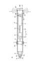
図7は、第3実施形態に係る入力デバイス60の内部構造を模式的に示す断面図である。Figure 7 is a cross-sectional view that shows a schematic internal structure of an
図7に示す入力デバイス60は、上記した入力デバイス10Aと比べて、音出力部26Aとは構成の異なる音出力部62を備え、連通経路27の代わりに金属棒体64を備える。音出力部62は、空洞空間26bの一面を形成する振動板66を有する。The
振動板66は、筐体20の外壁20bに形成された開口部20eを塞ぐように固定されている。振動板66は振動することで音を発生させる部品であり、一般的なスピーカーに設けられた振動板(コーン)と同様に構成することができる。入力デバイス60は、開口部20eを含む空間を空洞空間26bとして使用し、この空洞空間26bの一面を振動板66で閉塞した構成である。The
金属棒体64は、筐体20の長手方向に沿って延在する金属棒であり、例えば硬質のステンレス棒ある。金属棒体64は、一端部が振動発生部24に接続され、他端部が振動板66に接続されている。これにより金属棒体64は、音成分の駆動信号に従って振動発生部24が発生した音振動(音S)を振動板66へと伝達する振動伝達媒体として機能する。The
入力デバイス60では、振動発生部24が発生した音振動(音S)が金属棒体64を介して振動板66に伝達され、振動板66がアクティブラジエーターとして機能する。これにより入力デバイス60は、振動板66の振動によって空洞空間26bで増大された音Sを筐体20の外部へと出力することができる。金属棒体64の他端部は、振動板66に直接的に接続せず、空洞空間26b内に配置してもよい。この場合は、振動板66がパッシブラジエーターとして機能し、空洞空間26bで増大された音Sを筐体20の外部へと出力することができる。In the
図8は、第4実施形態に係る入力デバイス70の内部構造を模式的に示す断面図である。Figure 8 is a cross-sectional view showing a schematic internal structure of an
図8に示す入力デバイス70は、上記した入力デバイス10と比べて、音出力部26とは構成の異なる音出力部72を備え、連通経路27の代わりに金属棒体64を備える。音出力部72は、ペンクリップ74を有する。The
ペンクリップ74は、入力デバイス70を洋服のポケットの縁等に引っ掛ける際に使用できるクリップである。ペンクリップ74は、音振動(音S)を増幅可能な硬質なステンレス等の金属製であることが好ましい。金属棒体64は、一端部が振動発生部24に接続され、他端部がペンクリップ74に接続されている。ペンクリップ74は、金属棒体64と端部に一体に形成されていてもよい。ペンクリップ74は、筐体20の外壁20bに対して取り付ける構成でもよく、この場合は外壁20bに露出する金属棒体64の端部に接着剤等で強固に固定されるとよい。The
入力デバイス70では、音成分の駆動信号に従って振動発生部24が発生した音振動(音S)が金属棒体64を振動伝達媒体としてペンクリップ74まで伝達される。これによりペンクリップ74が図7に示す振動板66と同様な振動板として機能し、音Sを増大させて筐体20の外部へと出力することができる。In the
なお、本発明は、上記した実施形態に限定されるものではなく、本発明の主旨を逸脱しない範囲で自由に変更できることは勿論である。The present invention is not limited to the above-described embodiment, and can of course be freely modified without departing from the spirit of the present invention.
10,10A,10B,50,60,70 入力デバイス
12 情報処理システム
14 情報処理装置
20 筐体
20c ペン尻部
22 ペン先部
24 振動発生部
24a アクチュエータ
26,26A,26B,62,72 音出力部
26a,26c 孔部
26b 空洞空間
27 連通経路
48 ボタンスイッチ
52 キャップ状部材
64 金属棒体
66 振動板
74 ペンクリップ REFERENCE SIGNS
Claims (6)
Translated fromJapanese細長い棒状に形成された筐体と、
前記筐体の先端に設けられたペン先部と、
前記筐体内で該筐体の長手方向での中央よりも前記ペン先部に近い位置に配置され、振動成分と音成分を合成した駆動信号が入力されると共に、該駆動信号に従った振動を発生する振動発生部と、
前記振動発生部から離れた位置に設けられ、前記振動発生部が発生した前記音成分の駆動信号に従った音振動が振動伝達媒体を介して伝達されると共に、該音振動を前記筐体の外部に出力する音出力部と、
を備え、
前記合成した駆動信号は、前記振動成分として前記振動発生部に150~300Hzの周波数帯域を含む振動を発生させる駆動信号と、前記音成分として前記音出力部に500Hz~2kHzの周波数帯域を含む音を発生させる駆動信号と、を含み、
前記音出力部は、前記筐体の長手方向での中央よりも前記ペン先部とは反対側のペン尻部に近い位置に配置され、
前記音出力部は、前記筐体の外壁に貫通形成された孔部を有し、
さらに、前記筐体に設けられた開口部の一部を塞ぐように前記筐体に支持されたボタンスイッチを備え、
前記孔部は、前記ボタンスイッチと前記筐体との間に形成された隙間である
ことを特徴とする入力デバイス。 A pen-type input device,
A housing formed in a long and thin rod shape;
a pen tip portion provided at a tip of the housing;
a vibration generating unit that is disposed in the housing at a position closer to the pen tip unit than the center of the housing in the longitudinal direction, receives a drive signal that combines a vibration component and a sound component, and generates vibrations in accordance with the drive signal;
a sound output unit that is provided at a position away from the vibration generating unit, transmits sound vibrations generated by the vibration generating unit in accordance with the drive signal of the sound component via a vibration transmission medium, and outputs the sound vibrations to the outside of the housing;
Equipped with
The synthesized drive signal includes a drive signal that causes the vibration generating unit to generate a vibration having a frequency band of 150 to 300 Hz as the vibration component, and a drive signal that causes the sound output unit to generate a sound having a frequency band of 500 Hz to 2 kHz as the sound component,
the sound output unit is disposed at a position closer to a pen end portion on the opposite side to the pen tip portion than to a center in a longitudinal direction of the housing,
The sound output unit has a hole formed through an outer wall of the housing,
The electronic device further includes a button switch supported by the housing so as to cover a part of an opening provided in the housing,
The hole is a gap formed between the button switch and the housing.
1. An input device comprising:
前記筐体内には、該筐体の長手方向に沿って延在し、前記振動発生部と前記音出力部との間を接続する連通経路が形成され、
前記振動伝達媒体は、前記連通経路内の空気を含む
ことを特徴とする入力デバイス。 2. An input device accordingto claim 1 ,
a communication path is formed within the housing, the communication path extending along a longitudinal direction of the housing and connecting the vibration generating unit and the sound output unit;
The input device, wherein the vibration transmission medium includes air in the communication path.
細長い棒状に形成された筐体と、
前記筐体の先端に設けられたペン先部と、
前記筐体内で該筐体の長手方向での中央よりも前記ペン先部に近い位置に配置され、振動成分と音成分を合成した駆動信号が入力されると共に、該駆動信号に従った振動を発生する振動発生部と、
前記振動発生部から離れた位置に設けられ、前記振動発生部が発生した前記音成分の駆動信号に従った音振動が振動伝達媒体を介して伝達されると共に、該音振動を前記筐体の外部に出力する音出力部と、
を備え、
前記合成した駆動信号は、前記振動成分として前記振動発生部に150~300Hzの周波数帯域を含む振動を発生させる駆動信号と、前記音成分として前記音出力部に500Hz~2kHzの周波数帯域を含む音を発生させる駆動信号と、を含み、
前記音出力部は、前記筐体の長手方向での中央よりも前記ペン先部とは反対側のペン尻部に近い位置に配置され、
前記音出力部は、
前記筐体の内部に設けられ、前記振動伝達媒体を介して伝達された音振動を増大させる空洞空間と、
前記筐体の外壁に形成された開口部を塞ぐように設けられ、前記空洞空間の一面を形成する振動板と、
を有する
ことを特徴とする入力デバイス。A pen-type input device,
A housing formed in a long and thin rod shape;
a pen tip portion provided at a tip of the housing;
a vibration generating unit that is disposed in the housing at a position closer to the pen tip unit than the center of the housing in the longitudinal direction, receives a drive signal that combines a vibration component and a sound component, and generates vibrations in accordance with the drive signal;
a sound output unit that is provided at a position away from the vibration generating unit, transmits sound vibrations generated by the vibration generating unit in accordance with the drive signal of the sound component via a vibration transmission medium, and outputs the sound vibrations to the outside of the housing;
Equipped with
The synthesized drive signal includes a drive signal that causes the vibration generating unit to generate a vibration having a frequency band of 150 to 300 Hz as the vibration component, and a drive signal that causes the sound output unit to generate a sound having a frequency band of 500 Hz to 2 kHz as the sound component,
the sound output unit is disposed at a position closer to a pen end portion on the opposite side to the pen tip portion than to a center in a longitudinal direction of the housing,
The sound output unit is
a hollow space provided inside the housing for amplifying the sound vibration transmitted through the vibration transmission medium;
a diaphragm that is provided to close an opening formed in an outer wall of the housing and forms one side of the hollow space;
An input device comprising:
細長い棒状に形成された筐体と、
前記筐体の先端に設けられたペン先部と、
前記筐体内で該筐体の長手方向での中央よりも前記ペン先部に近い位置に配置され、振動成分と音成分を合成した駆動信号が入力されると共に、該駆動信号に従った振動を発生する振動発生部と、
前記振動発生部から離れた位置に設けられ、前記振動発生部が発生した前記音成分の駆動信号に従った音振動が振動伝達媒体を介して伝達されると共に、該音振動を前記筐体の外部に出力する音出力部と、
を備え、
前記合成した駆動信号は、前記振動成分として前記振動発生部に150~300Hzの周波数帯域を含む振動を発生させる駆動信号と、前記音成分として前記音出力部に500Hz~2kHzの周波数帯域を含む音を発生させる駆動信号と、を含み、
前記音出力部は、前記筐体の長手方向での中央よりも前記ペン先部とは反対側のペン尻部に近い位置に配置され、
前記音出力部は、前記筐体の外壁に取り付けられた金属製のペンクリップを有し、
前記振動伝達媒体は、前記筐体の長手方向に沿って延在し、前記振動発生部と前記ペンクリップとの間を接続する金属棒体を含む
ことを特徴とする入力デバイス。A pen-type input device,
A housing formed in a long and thin rod shape;
a pen tip portion provided at a tip of the housing;
a vibration generating unit that is disposed in the housing at a position closer to the pen tip unit than the center of the housing in the longitudinal direction, receives a drive signal that combines a vibration component and a sound component, and generates vibrations in accordance with the drive signal;
a sound output unit that is provided at a position away from the vibration generating unit, transmits sound vibrations generated by the vibration generating unit in accordance with the drive signal of the sound component via a vibration transmission medium, and outputs the sound vibrations to the outside of the housing;
Equipped with
The synthesized drive signal includes a drive signal that causes the vibration generating unit to generate a vibration having a frequency band of 150 to 300 Hz as the vibration component, and a drive signal that causes the sound output unit to generate a sound having a frequency band of 500 Hz to 2 kHz as the sound component,
the sound output unit is disposed at a position closer to a pen end portion on the opposite side to the pen tip portion than to a center in a longitudinal direction of the housing,
the sound output unit has a metal pen clip attached to an outer wall of the housing,
An input device, characterized in that the vibration transmission medium includes a metal rod extending along a longitudinal direction of the housing and connecting between the vibration generating unit and the pen clip.
細長い棒状に形成された筐体と、
前記筐体の先端に設けられたペン先部と、
前記筐体内で該筐体の長手方向での中央よりも前記ペン先部に近い位置に配置され、振動成分と音成分を合成した駆動信号が入力されると共に、該駆動信号に従った振動を発生する振動発生部と、
前記振動発生部から離れた位置に設けられ、前記振動発生部が発生した前記音成分の駆動信号に従った音振動が振動伝達媒体を介して伝達されると共に、該音振動を前記筐体の外部に出力する音出力部と、
を備え、
前記合成した駆動信号は、前記振動成分として前記振動発生部に150~300Hzの周波数帯域を含む振動を発生させる駆動信号と、前記音成分として前記音出力部に500Hz~2kHzの周波数帯域を含む音を発生させる駆動信号と、を含み、
前記音出力部は、前記筐体の長手方向での中央よりも前記ペン先部とは反対側のペン尻部に近い位置に配置され、
前記筐体に対して着脱可能に装着されたキャップ状部材を備え、
前記音出力部は、
前記キャップ状部材に設けられ、前記音振動を増大させる空洞空間と、
前記キャップ状部材の外壁に貫通形成され、前記空洞空間と連通する孔部と、
を有する
ことを特徴とする入力デバイス。A pen-type input device,
A housing formed in a long and thin rod shape;
a pen tip portion provided at a tip of the housing;
a vibration generating unit that is disposed in the housing at a position closer to the pen tip unit than the center of the housing in the longitudinal direction, receives a drive signal that combines a vibration component and a sound component, and generates vibrations in accordance with the drive signal;
a sound output unit that is provided at a position away from the vibration generating unit, transmits sound vibrations generated by the vibration generating unit in accordance with the drive signal of the sound component via a vibration transmission medium, and outputs the sound vibrations to the outside of the housing;
Equipped with
The synthesized drive signal includes a drive signal that causes the vibration generating unit to generate a vibration having a frequency band of 150 to 300 Hz as the vibration component, and a drive signal that causes the sound output unit to generate a sound having a frequency band of 500 Hz to 2 kHz as the sound component,
the sound output unit is disposed at a position closer to a pen end portion on the opposite side to the pen tip portion than to a center in a longitudinal direction of the housing,
a cap-shaped member detachably attached to the housing,
The sound output unit is
a hollow space provided in the cap-shaped member for amplifying the sound vibration;
a hole formed through an outer wall of the cap-shaped member and communicating with the hollow space;
An input device comprising:
前記振動伝達媒体は、前記筐体の長手方向に沿って延在し、前記振動発生部と前記音出力部との間を接続する金属棒体を含む
ことを特徴とする入力デバイス。 6. An input device according to claim5 ,
The input device, characterized in that the vibration transmission medium includes a metal rod extending along a longitudinal direction of the housing and connecting between the vibration generating unit and the sound output unit.
Priority Applications (1)
| Application Number | Priority Date | Filing Date | Title |
|---|---|---|---|
| JP2023221552AJP7637758B1 (en) | 2023-12-27 | 2023-12-27 | Input devices |
Applications Claiming Priority (1)
| Application Number | Priority Date | Filing Date | Title |
|---|---|---|---|
| JP2023221552AJP7637758B1 (en) | 2023-12-27 | 2023-12-27 | Input devices |
Publications (2)
| Publication Number | Publication Date |
|---|---|
| JP7637758B1true JP7637758B1 (en) | 2025-02-28 |
| JP2025103865A JP2025103865A (en) | 2025-07-09 |
Family
ID=94730614
Family Applications (1)
| Application Number | Title | Priority Date | Filing Date |
|---|---|---|---|
| JP2023221552AActiveJP7637758B1 (en) | 2023-12-27 | 2023-12-27 | Input devices |
Country Status (1)
| Country | Link |
|---|---|
| JP (1) | JP7637758B1 (en) |
Citations (5)
| Publication number | Priority date | Publication date | Assignee | Title |
|---|---|---|---|---|
| WO2008078523A1 (en) | 2006-12-25 | 2008-07-03 | Konica Minolta Holdings, Inc. | Handwriting electronic input system |
| JP2016014313A (en) | 2014-06-30 | 2016-01-28 | シナン セラミック カンパニー リミテッド | Water supply valve cartridge having left and right click type step operation means |
| WO2018030266A1 (en) | 2016-08-09 | 2018-02-15 | 日本電産サンキョー株式会社 | Pen-type haptic force delivery device |
| JP2019061547A (en) | 2017-09-27 | 2019-04-18 | 株式会社東海理化電機製作所 | Drive control device |
| JP2019185554A (en) | 2018-04-13 | 2019-10-24 | 株式会社デンソーテン | Sound output apparatus and sound output method |
- 2023
- 2023-12-27JPJP2023221552Apatent/JP7637758B1/enactiveActive
Patent Citations (5)
| Publication number | Priority date | Publication date | Assignee | Title |
|---|---|---|---|---|
| WO2008078523A1 (en) | 2006-12-25 | 2008-07-03 | Konica Minolta Holdings, Inc. | Handwriting electronic input system |
| JP2016014313A (en) | 2014-06-30 | 2016-01-28 | シナン セラミック カンパニー リミテッド | Water supply valve cartridge having left and right click type step operation means |
| WO2018030266A1 (en) | 2016-08-09 | 2018-02-15 | 日本電産サンキョー株式会社 | Pen-type haptic force delivery device |
| JP2019061547A (en) | 2017-09-27 | 2019-04-18 | 株式会社東海理化電機製作所 | Drive control device |
| JP2019185554A (en) | 2018-04-13 | 2019-10-24 | 株式会社デンソーテン | Sound output apparatus and sound output method |
Also Published As
| Publication number | Publication date |
|---|---|
| JP2025103865A (en) | 2025-07-09 |
Similar Documents
| Publication | Publication Date | Title |
|---|---|---|
| JP7087022B2 (en) | Human computer interface system | |
| FI115861B (en) | Method and apparatus for generating a response | |
| JP2014222492A (en) | Drawing device and drawing system | |
| CN102830816B (en) | Telescopic touch controlled pen and touch-control system | |
| JP2014132473A (en) | Touch-sensitive device | |
| JP2018121340A (en) | Electronic device | |
| CN114206452B (en) | Controller attachment with customizable presets | |
| JP2012533816A (en) | Signal generator | |
| CN108735194B (en) | Beat prompting method and device | |
| CN108769327A (en) | Method and device for sounding display screen, electronic device and storage medium | |
| JP7637758B1 (en) | Input devices | |
| JP2018063529A (en) | Keyboard, information processing apparatus, feedback method, and program | |
| US12436627B2 (en) | Input device with vibration generator and information processing system | |
| US8017847B1 (en) | Violin display | |
| US20240310931A1 (en) | Input device and information processing system | |
| KR100980691B1 (en) | Multifunction Ultrasonic Input Signal Generator | |
| JP2009238081A (en) | Touch panel type input device | |
| JP7534100B2 (en) | Sound detection device and sound detection system | |
| US20240402818A1 (en) | Pen including haptic element | |
| JP7434633B1 (en) | Information processing device, information processing system, input device and control method | |
| KR20160070232A (en) | Pen for mobile communication device having health care function | |
| JP7547546B2 (en) | Stylus pen and its pen tip | |
| JP7487385B1 (en) | Information processing system, pen-type input device, and program | |
| JP3344279B2 (en) | Control device | |
| JP4972791B2 (en) | Operation panel and input device |
Legal Events
| Date | Code | Title | Description |
|---|---|---|---|
| A621 | Written request for application examination | Free format text:JAPANESE INTERMEDIATE CODE: A621 Effective date:20231227 | |
| A711 | Notification of change in applicant | Free format text:JAPANESE INTERMEDIATE CODE: A711 Effective date:20240327 | |
| A131 | Notification of reasons for refusal | Free format text:JAPANESE INTERMEDIATE CODE: A131 Effective date:20240806 | |
| A521 | Request for written amendment filed | Free format text:JAPANESE INTERMEDIATE CODE: A523 Effective date:20241105 | |
| A131 | Notification of reasons for refusal | Free format text:JAPANESE INTERMEDIATE CODE: A131 Effective date:20241203 | |
| A521 | Request for written amendment filed | Free format text:JAPANESE INTERMEDIATE CODE: A523 Effective date:20250109 | |
| TRDD | Decision of grant or rejection written | ||
| A01 | Written decision to grant a patent or to grant a registration (utility model) | Free format text:JAPANESE INTERMEDIATE CODE: A01 Effective date:20250128 | |
| A61 | First payment of annual fees (during grant procedure) | Free format text:JAPANESE INTERMEDIATE CODE: A61 Effective date:20250217 | |
| R150 | Certificate of patent or registration of utility model | Ref document number:7637758 Country of ref document:JP Free format text:JAPANESE INTERMEDIATE CODE: R150 |