JP7637654B2 - Steering handle - Google Patents
Steering handleDownload PDFInfo
- Publication number
- JP7637654B2 JP7637654B2JP2022116561AJP2022116561AJP7637654B2JP 7637654 B2JP7637654 B2JP 7637654B2JP 2022116561 AJP2022116561 AJP 2022116561AJP 2022116561 AJP2022116561 AJP 2022116561AJP 7637654 B2JP7637654 B2JP 7637654B2
- Authority
- JP
- Japan
- Prior art keywords
- grip
- disposed
- operating lever
- gripping
- steering
- Prior art date
- Legal status (The legal status is an assumption and is not a legal conclusion. Google has not performed a legal analysis and makes no representation as to the accuracy of the status listed.)
- Active
Links
Images


Classifications
- B—PERFORMING OPERATIONS; TRANSPORTING
- B62—LAND VEHICLES FOR TRAVELLING OTHERWISE THAN ON RAILS
- B62D—MOTOR VEHICLES; TRAILERS
- B62D1/00—Steering controls, i.e. means for initiating a change of direction of the vehicle
- B62D1/02—Steering controls, i.e. means for initiating a change of direction of the vehicle vehicle-mounted
- B62D1/12—Hand levers
- B—PERFORMING OPERATIONS; TRANSPORTING
- B62—LAND VEHICLES FOR TRAVELLING OTHERWISE THAN ON RAILS
- B62D—MOTOR VEHICLES; TRAILERS
- B62D1/00—Steering controls, i.e. means for initiating a change of direction of the vehicle
- B62D1/02—Steering controls, i.e. means for initiating a change of direction of the vehicle vehicle-mounted
- B62D1/04—Hand wheels
- B62D1/046—Adaptations on rotatable parts of the steering wheel for accommodation of switches
- B—PERFORMING OPERATIONS; TRANSPORTING
- B60—VEHICLES IN GENERAL
- B60K—ARRANGEMENT OR MOUNTING OF PROPULSION UNITS OR OF TRANSMISSIONS IN VEHICLES; ARRANGEMENT OR MOUNTING OF PLURAL DIVERSE PRIME-MOVERS IN VEHICLES; AUXILIARY DRIVES FOR VEHICLES; INSTRUMENTATION OR DASHBOARDS FOR VEHICLES; ARRANGEMENTS IN CONNECTION WITH COOLING, AIR INTAKE, GAS EXHAUST OR FUEL SUPPLY OF PROPULSION UNITS IN VEHICLES
- B60K26/00—Arrangement or mounting of propulsion-unit control devices in vehicles
- B60K26/02—Arrangement or mounting of propulsion-unit control devices in vehicles of initiating means or elements
- B—PERFORMING OPERATIONS; TRANSPORTING
- B60—VEHICLES IN GENERAL
- B60T—VEHICLE BRAKE CONTROL SYSTEMS OR PARTS THEREOF; BRAKE CONTROL SYSTEMS OR PARTS THEREOF, IN GENERAL; ARRANGEMENT OF BRAKING ELEMENTS ON VEHICLES IN GENERAL; PORTABLE DEVICES FOR PREVENTING UNWANTED MOVEMENT OF VEHICLES; VEHICLE MODIFICATIONS TO FACILITATE COOLING OF BRAKES
- B60T7/00—Brake-action initiating means
- B60T7/02—Brake-action initiating means for personal initiation
- B60T7/08—Brake-action initiating means for personal initiation hand actuated
- B60T7/10—Disposition of hand control
- B60T7/102—Disposition of hand control by means of a tilting lever
- B—PERFORMING OPERATIONS; TRANSPORTING
- B62—LAND VEHICLES FOR TRAVELLING OTHERWISE THAN ON RAILS
- B62D—MOTOR VEHICLES; TRAILERS
- B62D1/00—Steering controls, i.e. means for initiating a change of direction of the vehicle
- B62D1/02—Steering controls, i.e. means for initiating a change of direction of the vehicle vehicle-mounted
- B62D1/04—Hand wheels
- B62D1/06—Rims, e.g. with heating means; Rim covers
- G—PHYSICS
- G05—CONTROLLING; REGULATING
- G05G—CONTROL DEVICES OR SYSTEMS INSOFAR AS CHARACTERISED BY MECHANICAL FEATURES ONLY
- G05G1/00—Controlling members, e.g. knobs or handles; Assemblies or arrangements thereof; Indicating position of controlling members
- G05G1/01—Arrangements of two or more controlling members with respect to one another
- B—PERFORMING OPERATIONS; TRANSPORTING
- B60—VEHICLES IN GENERAL
- B60K—ARRANGEMENT OR MOUNTING OF PROPULSION UNITS OR OF TRANSMISSIONS IN VEHICLES; ARRANGEMENT OR MOUNTING OF PLURAL DIVERSE PRIME-MOVERS IN VEHICLES; AUXILIARY DRIVES FOR VEHICLES; INSTRUMENTATION OR DASHBOARDS FOR VEHICLES; ARRANGEMENTS IN CONNECTION WITH COOLING, AIR INTAKE, GAS EXHAUST OR FUEL SUPPLY OF PROPULSION UNITS IN VEHICLES
- B60K26/00—Arrangement or mounting of propulsion-unit control devices in vehicles
- B60K26/02—Arrangement or mounting of propulsion-unit control devices in vehicles of initiating means or elements
- B60K2026/028—Acceleration input members mounted on steering wheel or column
- G—PHYSICS
- G05—CONTROLLING; REGULATING
- G05G—CONTROL DEVICES OR SYSTEMS INSOFAR AS CHARACTERISED BY MECHANICAL FEATURES ONLY
- G05G1/00—Controlling members, e.g. knobs or handles; Assemblies or arrangements thereof; Indicating position of controlling members
- G05G1/04—Controlling members for hand actuation by pivoting movement, e.g. levers
- G—PHYSICS
- G05—CONTROLLING; REGULATING
- G05G—CONTROL DEVICES OR SYSTEMS INSOFAR AS CHARACTERISED BY MECHANICAL FEATURES ONLY
- G05G1/00—Controlling members, e.g. knobs or handles; Assemblies or arrangements thereof; Indicating position of controlling members
- G05G1/08—Controlling members for hand actuation by rotary movement, e.g. hand wheels
Landscapes
- Engineering & Computer Science (AREA)
- Transportation (AREA)
- Mechanical Engineering (AREA)
- Chemical & Material Sciences (AREA)
- Combustion & Propulsion (AREA)
- Physics & Mathematics (AREA)
- General Physics & Mathematics (AREA)
- Automation & Control Theory (AREA)
- Braking Elements And Transmission Devices (AREA)
- Steering Controls (AREA)
- Mechanical Control Devices (AREA)
Description
Translated fromJapanese本発明は、回転操舵中心側に配置されるボス部と、ボス部の周囲に配置されて回転操舵時に把持する把持部と、ボス部と把持部との間の領域に配置される操作レバー部と、を備える構成のステアリングハンドルに関する。The present invention relates to a steering handle that includes a boss portion that is located on the center side of the rotary steering, a grip portion that is located around the boss portion and is gripped during rotary steering, and an operating lever portion that is located in the area between the boss portion and the grip portion.
従来、ステアリングハンドルとしては、ボス部と把持部との間に、アクセル操作とブレーキ操作とを入力可能な操作レバー部を、配設させる構成のものがあった(例えば、特許文献1参照)。この従来のステアリングハンドルでは、操作レバー部は、把持部の把持時に操作可能とされるもので、把持部の上面側において操作可能な第1操作部と、把持部の下面側において操作可能な第2操作部と、を有する構成とされていた。また、第1操作部は、把持部の上面側においてこの上面に略沿うように配置される押圧面を有して、この押圧面を下方へ押し込むように回転操作可能に、ボス部側に配置される回転軸部に軸支される構成であった。Conventionally, there has been a steering handle that has an operating lever section disposed between a boss section and a grip section, through which accelerator and brake operations can be input (see, for example, Patent Document 1). In this conventional steering handle, the operating lever section is operable when the grip section is gripped, and is configured to have a first operating section operable on the upper surface side of the grip section, and a second operating section operable on the lower surface side of the grip section. In addition, the first operating section has a pressing surface disposed on the upper surface side of the grip section so as to substantially follow this upper surface, and is configured to be supported by a rotating shaft disposed on the boss section side so as to be rotatable so as to press this pressing surface downward.
しかし、従来のステアリングハンドルでは、第2操作部は、第1操作部とは別の回転軸部により回転操作可能とされるものであり、操作レバー部は、2つの回転軸部を有する構成であることから、構成が簡便ではなかった。また、従来のステアリングハンドルでは、第1操作部に形成される押圧面が、第1操作部を回転操作させるための回転軸部の略上方となる位置に配置される構成であった。そのため、従来のステアリングハンドルでは、例えば、押圧面において、回転軸部の上方の領域を押圧した場合に、第1操作部を押し下げることが困難であり、安定して押下操作できなかった。However, in conventional steering handles, the second operating part is rotatably operated by a rotating shaft part separate from the first operating part, and the operating lever part has two rotating shaft parts, which makes the configuration not simple. Also, in conventional steering handles, the pressing surface formed on the first operating part is arranged in a position that is approximately above the rotating shaft part for rotating the first operating part. Therefore, in conventional steering handles, for example, when the area above the rotating shaft part is pressed on the pressing surface, it is difficult to press down the first operating part, and it is not possible to stably press it down.
本発明は、上述の課題を解決するものであり、簡便な構成として、かつ、安定して操作可能なステアリングハンドルを提供することを目的とする。The present invention aims to solve the above-mentioned problems by providing a steering handle that is simple in configuration and can be stably operated.
本発明に係るステアリングハンドルは、回転操舵中心側に配置されるボス部と、ボス部の周囲に配置されて回転操舵時に把持する把持部と、ボス部と把持部との間の領域に配置される操作レバー部と、を備える構成のステアリングハンドルであって、
操作レバー部が、ボス部側に設けられる回転軸部により軸支されて、把持部の把持時に、下方へ押し込むような押下操作と、上方へ持ち上げるような引上操作と、の2つの操作を可能として、アクセル操作とブレーキ操作とを入力させる構成とされて、
操作レバー部における押下操作面が、回転軸部から離隔した把持部側において、把持部における回転操舵中心軸と略直交するような上面からなる把持面と、ボス部の上面側を覆うように配置されるパッドの上面と、の間となる位置で、把持面に略沿うように配置され、
回転軸部が、パッドに覆われるようにして、把持部の下端面よりも上側となる位置に、配置されていることを特徴とする。 A steering handle according to the present invention is a steering handle including a boss portion disposed on the center side of a rotary steering wheel, a grip portion disposed around the boss portion and gripped during rotary steering, and an operating lever portion disposed in a region between the boss portion and the grip portion,
The operating lever portion is pivotally supported by a rotating shaft portion provided on the boss portion side, and when the grip portion is gripped, two operations, a push-down operation of pushing the lever downward and a pull-up operation of lifting the lever upward, are possible, and the operating lever portion is configured to input an accelerator operation and a brake operation,
a depression operation surface of the operating lever portion is disposed on the grip portion side separated from the rotation shaft portion, between a grip surface having an upper surface that is approximately perpendicular to the rotation steering central axis of the grip portion and an upper surface of a pad disposed so as to cover an upper surface side of the boss portion, and is disposed so as to approximately follow the grip surface;
The rotating shaft is characterized in that it is arranged at a position above the lower end surface of the grip portion so as to be covered by the pad.
本発明のステアリングハンドルでは、アクセル操作とブレーキ操作とに用いられる操作レバー部が、把持部の把持時に操作可能な構成であるとともに、下方へ押し込むような押下操作と、上方へ持ち上げるような引上操作と、の2つの操作を、ボス部側に設けられる1つの回転軸部による回転操作によって行なう構成とされている。そのため、回転軸部を2つ配設させている従来のステアリングハンドルの操作レバー部と比較して、簡便な構成とすることができる。また、本発明のステアリングハンドルでは、操作レバー部において、下方へ押し込むように操作させる押下操作面が、回転軸部を跨いで配設されることなく、回転軸部から離隔した把持部側に配設されていることから、押下操作面のどの領域を押圧しても、安定して押下操作することができる。さらに、本発明のステアリングハンドルでは、押下操作面が、把持部の把持面とパッドの上面との間となる位置に配置されており、また、回転軸部が、パッドに覆われるようにして、把持部の下端面よりも上側となる位置に、配置されている。すなわち、本発明のステアリングハンドルでは、押下操作面の押下操作時(回転操作時)の回転半径が比較的大きく、かつ、押下操作面が、回転軸部の略側方に配置されることとなる。押下操作面を押し下げる際の押圧力の入力の方向は、回転軸部を中心とした回転操作時の軌跡における接線方向に略沿う方向となるが、本発明のステアリングハンドルでは、この押圧力の入力の方向を、把持面に対して略直交する方向に近似させることが可能となり、押下操作面を、略直下に向かって押し下げれば、操作レバー部を、下方に押し込むように操作させることができる。そのため、押下操作面を強い力で押し下げなくとも、操作レバー部を下方に容易に押し込むことができる。さらにまた、本発明のステアリングハンドルでは、押下操作面が、把持部に近接した位置に配置される構成であることから、把持部を把持している運転者の手における親指の付け根付近の部位(掌における拇指球の部位)によって、押下操作面を押し下げるようにして操作することができる。すなわち、本発明のステアリングハンドルでは、掌における拇指球付近の広い面で、安定して押下操作面を押し下げることができることから、操作性が良好であり、また、このような拇指球付近の部位は、指先で押圧する場合と比較して力をかけやすいことから、押下状態を、所定時間、安定して維持することができる。その結果、このような押下操作によるブレーキ操作若しくはアクセル操作を、安定して行うことができる。In the steering wheel of the present invention, the operating lever section used for the accelerator operation and the brake operation is configured to be operable when the grip section is gripped, and two operations, a push-down operation to push down and a pull-up operation to lift up, are performed by rotating a single rotating shaft section provided on the boss section side. Therefore, compared with the operating lever section of a conventional steering wheel having two rotating shaft sections, the configuration is simpler. In addition, in the steering wheel of the present invention, the push-down operation surface for pushing down is not arranged across the rotating shaft section, but is arranged on the grip section side separated from the rotating shaft section, so that the push-down operation can be performed stably regardless of which area of the push-down operation surface is pressed. Furthermore, in the steering wheel of the present invention, the push-down operation surface is arranged between the grip surface of the grip section and the upper surface of the pad, and the rotating shaft section is arranged at a position above the lower end surface of the grip section so as to be covered by the pad. That is, in the steering wheel of the present invention, the rotation radius of the pressing operation surface during pressing (rotating) is relatively large, and the pressing operation surface is disposed approximately to the side of the rotating shaft. The direction of the pressing force input when pressing down the pressing operation surface is approximately along the tangential direction of the trajectory during the rotating operation centered on the rotating shaft, but in the steering wheel of the present invention, the direction of the pressing force input can be approximated to a direction approximately perpendicular to the grip surface, and by pressing the pressing operation surface approximately straight down, the operating lever part can be operated to be pressed downward. Therefore, the operating lever part can be easily pressed downward without pressing down the pressing operation surface with a strong force. Furthermore, in the steering wheel of the present invention, since the pressing operation surface is disposed in a position close to the grip, the pressing operation surface can be operated to be pressed down by the part near the base of the thumb of the driver's hand holding the grip (the part of the ball of the palm). That is, the steering wheel of the present invention has good operability because the pressing operation surface can be pressed down stably with a wide surface area of the palm near the ball of the foot, and because it is easier to apply force to such an area near the ball of the foot compared to pressing with the fingertips, the pressed state can be stably maintained for a predetermined period of time. As a result, braking or accelerating operations can be stably performed by pressing in this way.
したがって、本発明のステアリングハンドルでは、簡便な構成として、かつ、安定して操作することができる。Therefore, the steering handle of the present invention has a simple configuration and can be operated stably.
また、本発明のステアリングハンドルにおいて、回転軸部を、把持部における上下の略中央よりも上側となる位置に、配置させる構成とすれば、回転軸部と押下操作面との上下方向側での離隔距離を、一層小さくすることができて、押下操作面を押し下げる際の押圧力の入力の方向(回転軸部を中心とした回転操作時の軌跡における接線方向に略沿う方向)が、把持面に対して略直交する方向に、一層、近似することとなり、操作レバー部の下方への押下操作の操作性が、一層良好となって、好ましい。In addition, in the steering handle of the present invention, if the rotating shaft is configured to be located at a position above the approximate vertical center of the grip, the vertical separation distance between the rotating shaft and the pressing surface can be further reduced, and the direction of the input pressure when pressing down the pressing surface (a direction approximately along the tangent direction of the trajectory during rotation operation around the rotating shaft) becomes more similar to a direction approximately perpendicular to the grip surface, making it easier to press the operating lever downward, which is preferable.
さらに、上記構成のステアリングハンドルにおいて、操作レバー部を、上面側に押下操作面を有して把持面に略沿うように配置される押下操作部と、押下操作部における把持部側の端部側から下方に延びた下端側に配置される引上操作部と、を有して、
引上操作部を、下端面と、下端側において回転操舵中心軸に略沿うように配置されるボス部側の面と、を引上操作面とするように、構成し、
引上操作面を、把持部の下端面よりも下方の領域に、配置させる構成とすることが、好ましい。 Furthermore, in the steering handle having the above configuration, the operating lever portion has a push-down operation portion having a push-down operation surface on an upper surface side and arranged so as to be substantially aligned with the grip surface, and a pull-up operation portion arranged on a lower end side extending downward from an end side of the push-down operation portion on the grip portion side,
The lifting operation portion is configured so that a lower end surface and a surface on the boss portion side arranged so as to be substantially aligned with the rotation steering central axis at the lower end side are used as lifting operation surfaces,
It is preferable that the lifting operation surface be disposed in a region below the lower end surface of the grip portion.
上記構成のステアリングハンドルでは、引上操作部が、押下操作面を有する押下操作部における把持部側の端部側から下方に延びた下端側に配置される構成であり、この引上操作部における下端面と、下端側におけるボス部側の面と、から構成される引上操作面が、把持部の下端面よりも下方の領域に、配置される構成である。すなわち、上記構成のステアリングハンドルでは、引上操作面が、押下操作面と比較して、回転軸部に対して上下で離隔した位置に配置されることとなる。引上操作部を引き上げる際の引張力の入力の方向は、上述した押下操作面を押し下げる際の押圧力の入力の方向と同様に、回転軸部を中心とした回転操作時の軌跡における接線方向に略沿う方向となるが、引上操作面が、押下操作面よりも、回転軸部に対して上下で離隔した位置に配置されることから、この引張力の入力の方向が、把持面に対して傾斜しつつ把持部に接近するような斜め方向に沿うこととなる。そのため、把持部を把持している手において、親指を除いた4本の指(人差し指や中指等)を、引上操作部の下端側に形成される引上操作面に押し当てて、手前(把持部側)に引けば、操作レバー部を、把持部に対して持ち上げるように操作することができる。その結果、操作レバー部の把持部に対する持上操作時の操作性が良好となる。また、このような引上操作は、把持部を把持している手の指先で引上操作部を握り込むような操作によって、実現することができることから、引上状態を、所定時間、安定して維持することができる。In the steering handle of the above configuration, the lifting operation part is arranged at the lower end side extending downward from the end side of the grip part side of the push-down operation part having the push-down operation surface, and the lifting operation surface composed of the lower end surface of the lifting operation part and the surface of the boss part side at the lower end side is arranged in an area below the lower end surface of the grip part. That is, in the steering handle of the above configuration, the lifting operation surface is arranged at a position that is vertically separated from the rotating shaft part compared to the push-down operation surface. The direction of input of the pulling force when lifting the lifting operation part is approximately along the tangent direction of the trajectory during the rotation operation centered on the rotating shaft part, similar to the direction of input of the pressing force when pushing down the above-mentioned push-down operation surface, but since the lifting operation surface is arranged at a position vertically separated from the rotating shaft part than the push-down operation surface, the direction of input of this pulling force is along an oblique direction that approaches the grip part while inclining with respect to the grip surface. Therefore, by pressing the four fingers (index finger, middle finger, etc.) excluding the thumb on the hand gripping the gripping portion against the lifting operation surface formed on the lower end side of the lifting operation portion and pulling it toward you (towards the gripping portion), the operating lever portion can be operated to lift up relative to the gripping portion. As a result, the operability of the operating lever portion when lifting up the gripping portion is improved. In addition, since such a lifting operation can be achieved by gripping the lifting operation portion with the fingertips of the hand gripping the gripping portion, the lifted state can be stably maintained for a predetermined time.
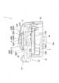
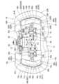
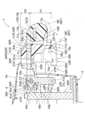
以下、本発明の一実施形態を図面に基づいて説明する。実施形態のステアリングハンドル1は、図1~3に示すように、回転操舵中心軸C1側に配置されるボス部5と、ボス部5の周囲に配置されて回転操舵時に把持する把持部10と、ボス部5と把持部10との間の領域に配置される操作レバー部50L,50Rと、を備えている。実施形態のステアリングハンドル1では、図1に示すように、把持部10は、直進操舵状態において、左右に幅広とした略四角環状とされており、操作レバー部50L,50Rは、左右一対として、ボス部5の右方と左方とに、配設されている。また、実施形態のステアリングハンドル1では、この左右一対の操作レバー部50L,50Rは、ボス部5内に配置されるリンク機構25によって、回転操作を同期される構成である。実施形態のステアリングハンドル1では、上下方向側から見た状態において、各操作レバー部50L,50Rは、図1,2に示すように、ボス部5の上面側に配置される後述するパッド6と、把持部10(後述するメイン把持領域13L,13R)と、の間の隙間を埋めるように、前後に広く配設されている。すなわち、実施形態のステアリングハンドル1では、把持部10におけるメイン把持領域13L,13Rと操作レバー部50L,50Rとの間に運転者の指等を進入できる構成ではなく、把持部10における後述する後側部位10c(ハンドレスト部16)とパッド6との間の隙間のみに、運転者の手(指)を進入させることが可能な構成である(図1参照)。An embodiment of the present invention will be described below with reference to the drawings. As shown in Figs. 1 to 3, the
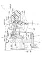
また、実施形態のステアリングハンドル1は、ボス部5と把持部10とを相互に連結するように配置される芯材3を、有している。芯材3は、アルミニウム合金等からなる板金製とされるもので、図1,3に示すように、把持部10の領域に配置される把持部側芯材3aと、ボス部5の領域に配置されるボス部側芯材3bと、把持部側芯材3aとボス部側芯材3bとを連結する連結部材3cと、を備えている。実施形態の場合、連結部材3cは、ボス部側芯材3bの後縁側と把持部側芯材3aの後側の領域とを連結するように、左右方向側の2箇所に、配設されている(図1,4参照)。The
なお、本明細書では、前後,上下,左右の方向は、特に断らない限り、車両に搭載させた状態のステアリングハンドル1の直進操舵状態を基準として、把持部10の回転操舵中心軸C1(図6参照)に沿った方向を上下方向とし、回転操舵中心軸C1と直交して車両の前後方向に略沿う方向を前後方向とし、回転操舵中心軸C1と直交して車両の左右方向に略沿う方向を左右方向としている。In this specification, unless otherwise specified, the forward/backward, upward/downward, and left/right directions are based on the straight-ahead steering state of the
ボス部5は、図1,6に示すように、芯材3におけるボス部側芯材3bと、ボス部側芯材3bの上方を覆う合成樹脂製のパッド6と、ボス部側芯材3bの側方と下方とを覆う合成樹脂製のロアカバー7と、を備えている。ロアカバー7は、図符号を付した説明を省略するが、ボス部側芯材3bと把持部側芯材3aとを連結する2つの連結部材3c,3cの周囲も、略全面にわたって覆うように構成されている(図1参照)。ボス部側芯材3bは、略平板状として、ボス部5の下端近傍に配置されている(図4~6参照)。ボス部側芯材3bの中央付近には、図示しないステアリングシャフトとの連結部位となるボス3baが、配設されている。また、ボス部5において、ボス部側芯材3bとパッド6との間における後述する台座部40L,40R間の領域には、図示しないエアバッグ装置が、収納されている。また、実施形態のステアリングハンドル1では、パッド6は、略全域にわたって、把持部10における把持面(具体的には、メイン把持領域13L,13Rにおける回転操舵中心軸C1と略直交するような上面13a)よりも上方となる位置に、配置されている(図6参照)。すなわち、パッド6の上面6aは、把持面13aよりも上方に位置している。1 and 6, the
把持部10は、直進操舵状態において左右に幅広とした略四角環状とされており、詳細には、平面視における前側中央の部位の外側を、上側から前側を経て下側にかけて、パッド6とロアカバー7とによって、覆われている(図1~3参照)。把持部10は、略四角環状とされる把持部側芯材3aの周囲に、クッション性を有した軟質合成樹脂製の被覆層11を、配設させて構成されている。把持部側芯材3aは、長尺の板状として、実施形態の場合、幅方向を、回転操舵中心軸C1と略直交させるように(すなわち、幅方向を、把持面13aに略沿わせるように)、配置されている(図6,7参照)。被覆層11は、発泡ポリウレタン等の軟質発泡材から形成されている。把持部10は、直進操舵状態において、略左右対称形とされている。The
把持部10は、直進操舵状態において前後方向に略沿って配設される左側部位10aと右側部位10bとを、操舵時に主に把持するメイン把持領域13L,13Rとして、構成されている。メイン把持領域13L,13Rは、略左右対称形とされるとともに、断面略楕円形状として構成されている(図1,5,6参照)。メイン把持領域13L,13Rの下端面13b側には、図6,7に示すように、上方に向かって僅かに凹ませるような凹部14L,14Rが、形成されている。この凹部14L,14Rは、詳細な図示は省略するが、メイン把持領域13L,13Rの略全域にわたって連続的に形成されるもので、操作レバー部50L,50Rの非操作状態あるいは押下操作の状態(非引上操作状態)でメイン把持領域13L,13Rを把持している運転者の手MHにおいて、親指以外の4本の指MFの指先Faを当てるための部位である(図7の二点鎖線参照)。詳細には、凹部14L,14Rは、メイン把持領域13L,13Rの内側にかけて上向きで傾斜するように(メイン把持領域13L,13Rにおける内側の領域の凹み量を大きくするように)、形成されている。このような凹部14L,14Rを設けることにより、メイン把持領域13L,13Rを把持している手MHの指先Faの位置を安定させることができて、把持状態を安定させることができる。各メイン把持領域13L,13Rは、上下方向側から見た状態において、前後の中央付近(詳細には、前後の中央よりやや後側となる位置)を、左右の外方に位置させるように、湾曲して形成されている。The gripping
把持部10において、直進操舵時の後端側において左右方向に略沿って配設される後側部位10cは、車両停止時等において、把持部10(メイン把持領域13L,13R等)から離した手を置いて休めるためのハンドレスト部16を構成するもので、メイン把持領域13L,13Rよりも上下で幅広として(メイン把持領域13L,13Rよりも上方に突出するように形成されて、図3参照)、図2に示すように、前面16a側を、手を休ませやすいように、平面状としている。ハンドレスト部16の左右の略中央には、上端側から部分的に凹ませるような凹部17が、形成されている。把持部10における直進操舵時の前端側において、パッド6の左方と右方(各メイン把持領域13L,13Rの前端とパッド6との間)に配設される左前側部位10d,右前側部位10eには、図1,2に示すように、上面側を凹ませるような凹部19L,19Rが、形成されている。具体的には、各凹部19L,19Rは、メイン把持領域13L,13Rに隣接した部位に、形成されている。この凹部19L,19Rは、各左前側部位10d,右前側部位10eにおける後面から上面を経て前面にかけて連続的に形成されるもので、この凹部19L,19Rには、詳細な図示は省略するが、メイン把持領域13L,13Rにおける前側の部位を把持している場合に、親指を収納することができる。In the gripping
操作レバー部50L,50Rは、ボス部5側に設けられる回転軸部43L,43Rに軸支されて、把持部10(メイン把持領域13L,13R)の把持時に、下方に押し込むような押下操作と、上方に持ち上げるような引上操作と、の2つの操作を可能として、アクセル操作とブレーキ操作とを入力させる構成とされている。実施形態のステアリングハンドル1では、押下操作時にアクセル操作を入力させ、引上操作時にブレーキ操作を入力させる構成である。詳細に後述するが、操作レバー部50L,50Rは、メイン把持領域13L,13Rを把持している運転者の手MHの親指MT側の領域によって押し下げられ、親指MT以外の他の指MF側の領域によって引き上げられるように、構成されている。操作レバー部50L,50Rの非操作状態あるいは引上操作の状態(すなわち、非押下操作状態)では、図1の二点鎖線に示すように、親指MTは、メイン把持領域13L,13Rの上面13a側に押し当てられることとなり、操作レバー部50L,50Rの非操作状態あるいは押下操作の状態(すなわち、非引上操作状態)では、図7の二点鎖線に示すように、親指MT以外の他の指MFの指先Faは、メイン把持領域13L,13Rの下端面13b側(凹部14L,14R内)に押し当てられることとなる。The operation levers 50L, 50R are supported by the rotating
また、実施形態のステアリングハンドル1では、左右の操作レバー部50L,50Rは、リンク機構25により回転動作を同期される構成であり、例えば、一方の操作レバー部50Rを、メイン把持領域13Rを把持しつつ引上操作すれば、他方の操作レバー部50Lは、手が離れた状態であっても、上方に持ち上げられるように回転することとなる。左右の操作レバー部50L,50Rの回転動作を同期可能なリンク機構25は、図4~6に示すように、ボス部5における前端側の領域内に配設されるもので、操作レバー部50L,50Rを取り付ける後述する台座部40L,40Rに取り付けられる取付ブラケット34に、取り付けられている。取付ブラケット34は、台座部40L,40Rの前面側において台座部40L,40R間を連結するように、上下方向に略沿って配設されている(図4,6参照)。In addition, in the
リンク機構25は、図4,8に示すように、カムユニット26と、カムユニット26から延びて操作レバー部50L,50R側に連結される一対のリンク36L,36Rと、リンク36L,36Rと操作レバー部50L,50Rとを連結させる連結杆37L,37Rと、を備えるもので、実施形態の場合、把持面13aよりも下方となる位置に、配設されている。カムユニット26は、回転操舵中心軸C1に略直交しつつ略前後方向に沿うように配置される回転軸部32に軸支されて、取付ブラケット34に連結されている。取付ブラケット34には、回転軸部32を挿入可能な挿入用筒部34aが、前方に突出するように、形成されている(図4,8参照)。カムユニット26は、カム部材27と、プッシャ28と、カムホルダ29と、を備えている。プッシャ28は、回転軸部32に対して回動不能に取り付けられるもので、内部に、図示しない圧縮コイルばねを、配設させている。カム部材27とカムホルダ29とは、回転軸部32に対して回動自在とされている。カムホルダ29は、カム部材27とリンク36L,36Rとを連結させるもので、カム部材27と一体的に回転軸部32に対して回転可能とされている。実施形態の場合、カムホルダ29は、中央付近を、回転軸部32に軸支されている。4 and 8, the
一対のリンク36L,36Rは、各操作レバー部50L,50Rに対応して配設されるもので、一端(端部36a)側を、中央付近を回転軸部32に軸支されるカムホルダ29の長手方向の端部29a,29b側に連結されて、回転軸部32を中心として点対称的に左方あるいは右方に延びるように配置されている(図6,8参照)。リンク36L,36Rと操作レバー部50L,50Rとを連結させる連結杆37L,37Rは、リンク36L,36Rの他端(端部36b)側から後方に延びるように配置されるもので、端部37a側を、操作レバー部50L,50Rにおける後述する取付基材51L,51Rに形成される連結片57L,57Rの下端57a側に連結される構成である(図4,6参照)。カムホルダ29は、操作レバー部50L,50Rの非操作状態(中立状態)においては、長手方向を上下方向に略沿わせるように配置されるもので、このとき、リンク36L,36Rは、カムホルダ29の上下方向側の端部29a,29b(回転軸部32の上方と下方と)から延びるような構成とされている(図6参照)。A pair of
そして、例えば、図11に示すような操作レバー部50Rの押下操作時には、操作レバー部50Rの回転に伴って、リンク36Rが移動し、カムホルダ29が、カム部材27とともに、回転軸部32を中心として左方に向かって回転することとなる。このとき、仮に、右側の操作レバー部50Rのみを押下操作した場合にも、カムホルダ29の回転移動に伴って、左側の操作レバー部50Lを連結させているリンク36Lも右方に向かうように移動することから、左側の操作レバー部50Lも、同期して、押し下げられることとなる。この押下操作時には、カム部材27の回転移動に伴って、プッシャ28の内部に配置される図示しない圧縮コイルばねが、圧縮されることとなる。逆に、図12に示すような操作レバー部50Rの引上操作時には、操作レバー部50Rの回転に伴うリンク36Rの移動によって、カムホルダ29が、カム部材27とともに、回転軸部32を中心として右方に向かって回転することとなり、このとき、仮に、右側の操作レバー部50Rのみを引上操作した場合にも、カムホルダ29の回転移動に伴って左側の操作レバー部50Lを連結させているリンク36Lも左方に向かうように移動することから、左側の操作レバー部50Lも、同期して、引き上げられることとなる。この引上操作時においても、カム部材27の回転移動に伴って、プッシャ28の内部に配置される図示しない圧縮コイルばねが、圧縮されることとなる。このような操作レバー部50L,50Rの操作状態(押下操作と引上操作)は、手を離せば、非操作状態に復元されることとなる。このとき、プッシャ28の内部に収納される圧縮コイルばねの復元により、カム部材27とカムホルダ29とが、中立状態に復帰するように回転移動することとなる。11, when the operating
操作レバー部50L,50Rは、ボス部5内に配置される台座部40L,40Rに取り付けられるもので、取付基材51L,51Rと、レバー本体60L,60Rと、を備えている。なお、実施形態では、右側に配置される操作レバー部50Rと台座部40Rとを例に採り、詳細に説明をする。左側の操作レバー部50L,台座部40Lは、右側の操作レバー部50R,台座部40Rと略左右対称形とされていることから、同一の図符号の末尾に「L」を付して、詳細な説明を省略する。The operating
操作レバー部50Rを取り付ける台座部40Rは、金属製として、ボス部側芯材3bから上方に延びるように形成されるもので、詳細には、ボス3baの右方において、前後方向に略沿うように配置されて、上端側に、メイン把持領域13R側(右側、左右の外方)に突出する取付部41Rを、有している(図5~7参照)。取付部41Rは、実施形態の場合、上面41aを、把持面13aと略一致した位置に配置させるように、構成されている(図7参照)。取付部41Rには、操作レバー部50Rを軸支させる回転軸部43Rが、配設されている。回転軸部43Rは、操作レバー部50Rにおける取付基材51Rに形成される軸受部54Rに挿通されて操作レバー部50Rを軸支するもので、実施形態の場合、把持面13aに略沿いつつ、前後方向に略沿うように、配設されている(図5,7参照)。すなわち、回転軸部43Rは、ボス部5の領域内に、配設されている。この回転軸部43Rは、詳細には、把持面13aより僅かに下方となる位置に配置されるもので、換言すれば、パッド6に覆われるようにして、把持部10(具体的には、メイン把持領域13R)の上下の略中央よりも上側となる位置に、配置されている。具体的には、回転軸部43Rは、軸芯C2を、メイン把持領域13Rの上下の幅寸法において上から1/6程度となる位置に、配置させている(図7参照)。取付部41Rにおける回転軸部43Rよりも元部側(左側であって、左右方向の中央側)には、操作レバー部50Rの操作時の回転角度を規制するストッパ45Rが、配設されている。ストッパ45Rは、回転軸部43Rに軸支されている取付基材51Rにおける後述する横杆部53Rの先端53a側において上下方向側で先細り形状とされている先端部55Rの上方と下方とを覆うように配設されるもので、この先端部55Rの上面55a若しくは下面55bをそれぞれ当接可能な上側当接面45a,下側当接面45bを、備えている(図7,11,12参照)。上側当接面45a及び下側当接面45bは、先細り状の先端部55Rの上面55a,下面55bに広い面で当接可能に、それぞれ、傾斜して形成されている。The
操作レバー部50Rにおける取付基材51Rは、金属製とされて、上下方向側から見て略逆L字形状とされるもので、前後方向に略沿って配置される縦杆部52Rと、縦杆部52Rの後端から左方(左右の中央側)に突出するように左右方向に略沿って配置される横杆部53Rと、を有する構成とされている(図9参照)。縦杆部52Rは、レバー本体60Rにおける前側の領域内に配置されるもので、具体的には、レバー本体60Rの押下操作部61Rにおいて、後述する突出端60aよりも前側の領域内に、配置されている。縦杆部52Rの後端から延びる横杆部53Rは、レバー本体60Rの前後の中央付近から左方(左右の中央側)に突出するもので、具体的には、レバー本体60Rにおける突出端60a近傍部位から左方に突出するように、配置されている。横杆部53Rの先端53a側には、回転軸部43Rを挿通可能に貫通して形成される軸受部54Rが、形成されている。横杆部53Rにおいて、軸受部54Rよりも先端53a側となる先端部55Rは、上述したごとく、上下方向側で先細り形状とされており、この先端部55Rの上面55a及び下面55bを、それぞれ、台座部40Rに設けられるストッパ45Rに当接可能な構成とされている。また、横杆部53Rの先端53a側には、軸受部54Rの略直下の領域において、下方に延びるような連結片57Rが、形成されており、連結片57Rの下端57a側には、軸受部54Rの略直下となる位置で、上述したごとく、連結杆37Rの端部37aが、連結されている(図4,7参照)。The mounting
レバー本体60Rは、合成樹脂製とされるもので、実施形態の場合、ステアリングハンドル1を上下方向側から見た状態で、パッド6と、把持部10におけるメイン把持領域13Rと、の間の隙間を略埋めるように配置されている。詳細には、レバー本体60Rは、上下方向側から見た状態で、メイン把持領域13Rに略沿って前後に延びるように、メイン把持領域13Rの前後の略全域にわたって、配設される構成である(図1,2参照)。さらに詳細には、レバー本体60Rは、メイン把持領域13Rの湾曲形状に略沿うように、上下方向側から見た状態で、前後の中間部位(詳細には前後の中央よりやや後側の部位)を、左右の外方(右方)に突出させるように湾曲して、形成されている。レバー本体60Rは、把持面13aに略沿うように配置される押下操作部61Rと、押下操作部61Rにおける把持部10(メイン把持領域13R)側の端部61b側から下方に延びるように配置される引上操作部75Rと、を有して、断面略逆L字形状とされている(図6,7参照)。The
押下操作部61Rは、把持部10(メイン把持領域13R)に近接した位置において、把持面13aに略沿うとともに、把持部10(メイン把持領域13R)に略沿って前後に延びるように配設されるもので、実施形態の場合、上述したごとく、メイン把持領域13Rの前後の略全域にわたって、配設されている。また、押下操作部61Rは、メイン把持領域13Rの左側(把持部10の内側)において、間に僅かな隙間を設けられた状態で隣接されている。押下操作部61Rの上面61a側には、押下操作面62Rが、形成されている。押下操作面62Rは、図5,9,10に示すように、操作面本体63Rと、操作面本体63Rにおける把持部10側の縁部63a(外縁)に形成される傾斜面70Rと、を備えている。操作面本体63Rは、前後の中間部位に配置される天井面64Rと、天井面64Rの前縁64a側に形成される前側傾斜部65Rと、天井面64Rの後縁64b側に形成される後側傾斜部66Rと、を備えている。傾斜面70Rは、操作面本体63Rから下降しつつ把持部10側(メイン把持領域13R側)に接近するように、操作面本体63Rに対して傾斜するように配置されている。具体的には、実施形態の場合、傾斜面70Rは、操作面本体63Rにおいて、前側傾斜部65Rの外方(右方)を除いた領域(天井面64Rと後側傾斜部66Rとの外方(右方)の領域)に、形成されている。The
操作面本体63Rにおける天井面64Rは、パッド6の上面6aと把持面(メイン把持領域13Rにおける上面13a)との間となる位置において、把持面13aに略沿うように配置されている(図6,7参照)。詳細には、実施形態の場合、天井面64Rは、傾斜面70R側(メイン把持領域13R側)にかけて僅かに下降するように、把持面13aに対して僅かに傾斜している。操作面本体63Rにおける前側傾斜部65Rは、天井面64Rの前縁64a側において、天井面64Rから下降しつつ把持部10(詳細には右前側部位10e)に接近するように、天井面64Rに対して傾斜して配置されている(図10参照)。実施形態の場合、前側傾斜部65Rは、平面視において、押下操作面62Rの前後の全長の1/5程度の領域に、形成されている(図1参照)。また、実施形態の場合、前側傾斜部65Rは、天井面64Rの外縁(右縁)64c側に形成される傾斜面70R(具体的には、傾斜面70Rにおける前側部位71R)から、なだらかに連なるように形成されている。傾斜面70Rにおける前側部位71Rと、前側傾斜部65Rと、は、把持部10側の端縁(外縁71a,前縁65a)を、把持面13aと略同等となる位置に配置させるように、構成されている(図10参照)。後側傾斜部66Rは、天井面64Rの後縁64b側において、天井面64Rから下降しつつ把持部10(詳細にはハンドレスト部16)に接近するように、天井面64R(すなわち、把持面13a)に対して傾斜して配置されている。後側傾斜部66Rは、平面視において、前後に広く、押下操作面62Rの前後の全長の2/5程度の領域に、形成されており、具体的には、レバー本体60Rにおいて最も右方に突出している突出端60aから後側の領域に、形成されている(図1,9参照)。傾斜面70Rにおいて、後側傾斜部66Rの外側(右側)に配置される後側部位72Rは、図10に示すように、後端72a側にかけて収束するように、形成されている。また、後側傾斜部66Rは、把持部10側となる後縁66aを、把持面13aよりも下方に位置させるように、構成されている(図10参照)。具体的には、実施形態の場合、後側傾斜部66Rの後縁66aは、メイン把持領域13Rの上下の幅寸法において上から1/3程度となる位置に、配置されている(図10参照)。また、実施形態の場合、傾斜面70Rにおける前側部位71Rの把持面13aに対する傾斜角度αは、45°程度に設定され(図7参照)、前側傾斜部65Rの把持面13aに対する傾斜角度βは、20°程度に設定され、後側傾斜部66Rの把持面13aに対する傾斜角度γは、30°程度に設定されている(図10参照)。The
引上操作部75Rは、押下操作部61Rにおいて把持部10(メイン把持領域13R)側となる端部61b(外側の端部、右端)側から下方に(すなわち、回転操舵中心軸C1に略沿って)延びた下端側に配置されるもので、下端75aを、把持部10(メイン把持領域13R)の下端面13b(詳細には、外側下端面13c)よりも下方に位置させるように構成されている(図6,7参照)。具体的には、引上操作部75Rは、押下操作部61Rから延びた下端75a側において、上下方向に略沿った薄肉の略板状とされる領域を操作本体76Rとして、構成されている。この操作本体76Rは、図7に示すように、全体を、メイン把持領域13Rにおける凹部14Rの凹みの先端面(すなわち、内側下端面13d)よりも下方に位置させるように、構成されている。この操作本体76Rは、レバー本体60Rにおける外縁60b側であって、押下操作面62Rにおける傾斜面70Rの略直下となる位置に、形成されている。操作本体76Rの下端76a側には、メイン把持領域13R側となる右側(外側)に向けるように突出する湾曲部77Rが、形成されている。そして、この操作本体76Rは、ボス部5側の面(内側面76b)から湾曲部77Rの下端面77aにかけてを、引上操作面78Rとして、構成されている。引上操作面78Rは、詳細には、天井面64Rと傾斜面70Rとの境界部位の略直下となる位置(すなわち、天井面64Rよりも左右の外方となる位置)に、形成されている(図7参照)。実施形態の場合、引上操作面78Rと回転軸部43Rにおける軸芯C2との上下方向側での離隔距離(具体的には、引上操作面78Rの上下の略中央と軸芯C2との離隔距離H1、図7参照)は、押下操作面62Rにおける天井面64Rと、回転軸部43Rにおける軸芯C2と、の上下方向側での離隔距離H2より大きく、具体的には、この離隔距離H2の8/3程度に、設定されている。また、引上操作部75R(操作本体76R)は、レバー本体60Rの前後の略全域にわたって、連続的に、形成されている(図4参照)。すなわち、引上操作部75Rは、メイン把持領域13Rに略沿って前後に延びるように、メイン把持領域13Rの前後の略全域にわたって配設されている。そして、引上操作部75Rの前端75b側には、図4,7,9に示すように、ボス部5側(左方、左右の中央側)に向かって延びるような延設部80Rが、配設されている。実施形態の場合、延設部80Rは、操作本体76Rの下半部程度の領域を延ばすようにして、形成されるもので、レバー本体60Rの幅方向の略全域にわたるように、形成されている。The lifting
実施形態のステアリングハンドル1では、押下操作部61Rの最大押下角度θ1と、引上操作部75Rの最大引上角度θ2と、は、ともに、15°程度に設定されている(図11,12参照)。押下操作部61Rは、最大押下時に、図11に示すように、天井面64Rを把持面13aより下方に位置させるように構成され、引上操作部75Rは、最大引上時に、図12に示すように、操作本体76Rとメイン把持領域13Rとの間に僅かに隙間を設けられるように、構成されている。In the
そして、実施形態のステアリングハンドル1では、アクセル操作とブレーキ操作とに用いられる操作レバー部50L,50Rが、把持部10の把持時に操作可能な構成であるとともに、下方へ押し込むような押下操作と、上方へ持ち上げるような引上操作と、の2つの操作を、ボス部5側に設けられる1つの回転軸部43L,43Rによる回転操作によって行なう構成とされている。そのため、回転軸部を2つ配設させている従来のステアリングハンドルの操作レバー部と比較して、簡便な構成とすることができる。また、実施形態のステアリングハンドル1では、操作レバー部50L,50Rにおいて、下方へ押し込むように操作させる押下操作面62L,62Rが、回転軸部を跨いで配設されることなく、図5,6に示すように、回転軸部43L,43Rから離隔した把持部10(メイン把持領域13L,13R)側に配設されていることから、押下操作面62L,62Rのどの領域を押圧しても、安定して押下操作することができる。In the
さらに、実施形態のステアリングハンドル1では、押下操作面62L,62R(具体的には、操作面本体63L,63Rにおける天井面64L,64R)が、把持部10の把持面13aとパッド6の上面6aとの間となる位置に配置されており、また、回転軸部43L,43Rが、パッド6に覆われるようにして、把持部10(メイン把持領域13L,13R)の下端面13bよりも上側となる位置に、配置されている。すなわち、実施形態のステアリングハンドル1では、押下操作面62L,62R(天井面64L,64R)の押下操作時(回転操作時)の回転半径r1が比較的大きく(図11参照)、かつ、押下操作面62L,62R(天井面64L,64R)が、回転軸部43L,43Rの略側方に配置されることとなる。天井面64L,64Rを押し下げる際の押圧力F1の入力の方向は、回転軸部43L,43Rを中心とした回転操作時の軌跡R1における接線方向D1に略沿う方向となるが、実施形態のステアリングハンドル1では、この押圧力F1の入力の方向を、図11に示すように、把持面13aに対して略直交する方向に近似させることが可能となり、天井面64L,64Rを、略直下に向かって押し下げれば、操作レバー部50L,50Rを、下方へ押し込むように操作させることができる。そのため、押下操作面62L,62R(天井面64L,64R)を強い力で押し下げなくとも、操作レバー部50L,50Rを下方に容易に押し込むことができる。Furthermore, in the
さらにまた、実施形態のステアリングハンドル1では、押下操作面62L,62R(天井面64L,64R)が、把持部10(メイン把持領域13L,13R)に近接した位置に配置される構成であることから、把持部10(メイン把持領域13L,13R)を把持している運転者の手MHにおける親指MTの付け根付近の部位(掌における拇指球TBの部位)によって、押下操作面62L,62R(天井面64L,64R)を押し下げるようにして操作することができる。すなわち、実施形態のステアリングハンドル1では、掌における拇指球TB付近の広い面で、安定して押下操作面62L,62R(天井面64L,64R)を押し下げることができることから、操作性が良好であり、また、このような拇指球TB付近の部位は、指先で押圧する場合と比較して力をかけやすいことから、押下状態を、所定時間、安定して維持することができる。その結果、このような押下操作によるブレーキ操作若しくはアクセル操作を、安定して行うことができる。Furthermore, in the
したがって、実施形態のステアリングハンドル1では、簡便な構成として、かつ、安定して操作することができる。Therefore, the steering handle 1 of this embodiment has a simple configuration and can be operated stably.
また、実施形態のステアリングハンドル1では、回転軸部43L,43Rが、把持部10(メイン把持領域13L,13R)における上下の略中央よりも上側となる位置に、配置される構成である。そのため、回転軸部43L,43Rと押下操作面62L,62R(天井面64L,64R)との上下方向側での離隔距離を、一層小さくすることができて、天井面64L,64Rを押し下げる際の押圧力F1の入力の方向(回転軸部43L,43Rを中心とした回転操作時の軌跡R1における接線方向D1に略沿う方向)が、把持面13aに対して略直交する方向に、一層、近似することとなり、操作レバー部50L,50Rの下方への押下操作の操作性が、一層良好となる。実施形態のステアリングハンドル1では、押下操作の始点と終点とにおける把持面13aに沿った方向側の離隔距離t1が小さいことから(図11参照)、押下操作面62L,62Rを略直下に押し下げれば、最大押下状態まで、容易に押し下げることができる。なお、このような点を考慮しなければ、回転軸部を、把持部における上下の略中央よりも下側となる位置に、配置させる構成としてもよい。In addition, in the steering handle 1 of the embodiment, the rotating
さらに、実施形態のステアリングハンドル1では、操作レバー部50L,50Rに形成される引上操作部75L,75Rが、押下操作部61L,61Rにおける把持部10(メイン把持領域13L,13R)側の端部61b側から下方に延びた下端側に配置される構成であり、この引上操作部75L,75Rにおける下端面(湾曲部77の下端面77a)と、下端側のボス部5側の面(内側面76b)と、から構成される引上操作面78L,78Rが、把持部13の下端面13b(詳細には、内側下端面13d)よりも下方の領域に、配置される構成である。すなわち、実施形態のステアリングハンドル1では、引上操作面78L,78Rが、押下操作面62L,62Rと比較して、回転軸部43L,43Rに対して上下で離隔した位置に配置されることとなる。引上操作部75L,75Rを引き上げる際の引張力F2の入力の方向は、上述した押下操作面62L,62R(天井面64L,64R)を押し下げる際の押圧力F1の入力の方向と同様に、回転軸部43L,43Rを中心とした回転操作時の軌跡R2における接線方向D2に略沿う方向となるが、引上操作面78L,78Rが、天井面64L,64Rよりも、回転軸部43L,43Rに対して上下で離隔した位置に配置されることから、この引張力F2の入力の方向(接線方向D2)が、図12に示すごとく、把持面13aに対して傾斜しつつ把持部10に接近するような斜め方向に沿うこととなる(引上操作の始点と終点とにおける把持面13aに沿った方向側の離隔距離t2が、押下操作の始点と終点とにおける把持面13aに沿った方向側の離隔距離t1と比較して大きい、図11,12参照)。そのため、把持部10(メイン把持領域13L,13R)を把持している手において、親指を除いた4本の指F(人差し指や中指等)の指先Faを、引上操作部75L,75Rの下端75a側に形成される引上操作面78L,78Rに押し当てて、手前(把持部10側)に引けば、操作レバー部50L,50Rを、把持部10に対して持ち上げるように操作することができる。その結果、操作レバー部50L,50Rの把持部10(メイン把持領域13L,13R)に対する持上操作時の操作性が良好となる。また、このような引上操作は、メイン把持領域13L,13Rを把持している手MHの指先Faで引上操作部75L,75Rを握り込むような操作によって、実現することができることから(図14参照)、引上状態を、所定時間、安定して維持することができる。Furthermore, in the steering handle 1 of the embodiment, the lifting
実施形態のステアリングハンドル1では、操作レバー部50L,50Rの押下操作あるいは引上操作により、車両の速度調整を行う構成である。このようなステアリングハンドル1は、下肢等に障害のある人のための車両に搭載されることを考慮されている。具体的には、実施形態のステアリングハンドル1では、操作レバー部50L,50Rの押下操作時にアクセル操作を入力し、引上操作時にブレーキ操作を入力する構成である。アクセル操作もブレーキ操作も、所望の速度まで変更(加速あるいは減速)させるために、操作状態を所定の時間維持する必要があり、また、通常、押下量や引上量が大きくなればなるほど、操作する運転者の手にかかる負荷も大きくなる。すなわち、大きな力で所定時間、操作レバー部50L,50Rの押下状態や引上状態を維持する必要がある。また、通常、運転時には、ブレーキよりもアクセルの方が操作機会が多く、また、操作時間も長い。In the
実施形態のステアリングハンドル1では、操作レバー部50L,50Rの押下操作時に、アクセル操作を入力する構成であり、上述したごとく、把持部10(メイン把持領域13L,13R)を把持している運転者の手MHにおける親指MTの付け根付近の部位(掌における拇指球TBの部位)によって、押下操作面62L,62R(天井面64L,64R)を略直下に押し下げるようにして、押下操作する構成である。また、押下操作面62L,62Rは、実際に押下される天井面64L,64Rの把持部10(メイン把持領域13L,13R)側の縁部に、傾斜面70L,70Rを配設させている。そのため、メイン把持領域13L,13Rを把持している手MHにおける拇指球TBの部位付近を、傾斜面70L,70Rをガイドとして、内側(操作レバー部50L,50R側)に向かってずらしつつ、押し込めば、天井面64L,64Rを押し下げることができて(図13参照)、操作性が良好である。また、大きな力をかけやすい拇指球TB付近の部位によって、広い面で、安定して、天井面64L,64Rを押し下げることができることから、押下状態も、所定時間、安定して維持することができる。さらに、メイン把持領域13L,13Rの下面側には、上方に僅かに凹むような凹部14L,14Rが形成されていることから、親指MT以外の4本の指MFを、この凹部14L,14Rの内周面に指先Faを当てるようにして、メイン把持領域13L,13Rを把持すれば、押下操作時において、親指MTの付け根付近が内側にずれるように移動しても、メイン把持領域13L,13Rの把持状態を安定して維持することができる。すなわち、このような凹部14L,14Rを設けることにより、メイン把持領域13L,13Rの把持状態を安定させることができて、親指MTの付け根付近の部位(掌における拇指球TBの部位)による押下操作も、安定して行うことができる。In the
さらに詳細には、実施形態のステアリングハンドル1では、押下操作部61L,61Rの上面61a側に形成される押下操作面62L,62Rの操作面本体63L,63Rは、前後の中間部位に、把持面13aに略沿わせた天井面64L,64Rを配置させ、天井面64L,64Rの前縁64a側と後縁64b側とに、天井面64L,64Rから下降しつつ把持部10側に接近するような前側傾斜部65L,65Rと後側傾斜部66L,66Rとを、配設させている。そのため、メイン把持領域13L,13Rにおける前後の中央付近(天井面64L,64Rの側方の領域)から外れた前端側あるいは後端側の領域を把持している場合にも、メイン把持領域13L,13Rを把持している手MHを内側(操作レバー部50L,50R側)に向かってずらした際に、親指MTによって、前側傾斜部65L,65R若しくは後側傾斜部66L,66Rを円滑に押し下げることができる。また、前側傾斜部65L,65Rを設けることにより、例えば、運転者が、把持部10における左前側部位10d,右前側部位10eに形成される凹部19L,19Rに親指の先端を当てるようにして、メイン把持領域13L,13Rにおける前側の部位を把持している場合に、親指の付け根の部位が、なだらかに傾斜する前側傾斜部65L,65Rの領域に当たるような態様となる。さらに、後側傾斜部66L,66Rは、把持部10側となる後縁66aを、把持面13aよりも下方に位置させるように、構成されている。そのため、メイン把持領域13L,13Rにおける後側の領域を把持している場合に、親指の付け根付近となる拇指球付近の領域を、スムーズに後側傾斜部66L,66R上にずらすことができて、また、この後側傾斜部66L,66Rを拇指球付近の領域で、安定して押し下げることができる。In further detail, in the steering handle 1 of the embodiment, the operation surface
さらに、実施形態のステアリングハンドル1では、操作レバー部50L,50Rの引上操作時に、ブレーキ操作を入力する構成であり、上述したごとく、把持部10(メイン把持領域13L,13R)を把持している運転者の手MHにおける親指MT以外の指MF(人差し指や中指等)の指先Faを引上操作面78L,78Rに押し当てて、手前(把持部10(メイン把持領域13L,13R)側)に引くことにより、操作レバー部50L,50Rを、上方に持ち上げるように引上操作する構成である(図14参照)。このような引上操作は、メイン把持領域13L,13Rを把持している手MHの指先Faで引上操作部75L,75Rの操作本体76L,76Rを握り込むような操作によって、実現することができることから、操作性が良好である。特に、実施形態のステアリングハンドル1では、引上操作面78L,78Rが、押下操作面62L,62Rにおける天井面64L,64Rと比較して、回転軸部43L,43Rに対して上下に離れた位置で配置され、かつ、天井面64L,64Rよりも左右の外方に配置される構成である。すなわち、引上操作部75L,75Rは、押下操作部61L,61Rの操作時の回転半径r1と比較して、操作時の回転半径r2を大きくされることとなり(図11,12参照)、引上操作時のトルクを、押下操作部61L,61Rの押下操作時のトルクよりも小さくできることから、押下操作と比較して、小さな引張力(軽い力)で操作することが可能となる。さらに、引上操作部75L,75Rにおける操作本体76L,76Rが、レバー本体60L,60Rの外縁60b側に形成されていることから、メイン把持領域13L,13Rを把持している手MHの指先Faから近く、指先Faによる握り込みが容易である。その結果、親指を除いた4本の指の指先で引き上げる構成であっても、操作性が良好で、かつ、引上状態を、所定時間、安定して維持することができる。Furthermore, in the
また、実施形態のステアリングハンドル1では、操作レバー部50L,50Rにおいて、押下操作部61L,61Rの上面61a側に形成される押下操作面62L,62Rが、図2,9,10に示すように、メインで押し下げられる天井面64L,64Rの周縁において、パッド6側(内側)を除いた三方を、下方にかけて傾斜させている構成であり、すなわち、内縁側を除いた三辺を面取りされたような形状とされていることから、拇指球TB付近の部位をずれ移動させるような押下操作部61L,61Rの操作時に、操作レバー部50L,50Rが、運転者の手に部分的に食い込んだり、部分的に強く当たることを抑制でき、快適に、操作することができる。In addition, in the
なお、実施形態のステアリングハンドル1では、操作レバー部50L,50Rの押下操作時にアクセル操作を入力し、引上操作時にブレーキ操作を入力する構成であるが、勿論、押下操作時にブレーキ操作を入力し、引上操作時にアクセル操作を入力させる構成としてもよい。しかしながら、アクセル操作の方がブレーキ操作よりも操作機会が多く、また、操作時間も長い点や、押下操作の方が、引上操作と比較して大きな力をかけやすいという点等からは、実施形態のごとく、押下操作時にアクセル操作を入力し、引上操作時にブレーキ操作を入力する構成とすることが好ましい。In the
1…ステアリングハンドル、5…ボス部、6…パッド、6a…上面、10…把持部、13a…把持面、13b…下端面、回転軸部43L,43R、50L,50R…操作レバー部、60L,60R…レバー本体、61L,61R…押下操作部、62L,62R…押下操作面、75L,75R…引上操作部、75a…下端、78L,78R…引上操作面、C1…回転操舵中心軸。1...Steering handle, 5...Boss portion, 6...Pad, 6a...Top surface, 10...Grip portion, 13a...Grip surface, 13b...Lower end surface,
Claims (3)
Translated fromJapanese該操作レバー部が、前記ボス部側に設けられる回転軸部により軸支されて、前記把持部の把持時に、下方へ押し込むような押下操作と、上方へ持ち上げるような引上操作と、の2つの操作を可能として、アクセル操作とブレーキ操作とを入力させる構成とされて、
前記操作レバー部における押下操作面が、前記回転軸部から離隔した前記把持部側において、前記把持部における回転操舵中心軸と略直交するような上面からなる把持面と、前記ボス部の上面側を覆うように配置されるパッドの上面と、の間となる位置で、該把持面に略沿うように配置され、
前記回転軸部が、前記パッドに覆われるようにして、前記把持部の下端面よりも上側となる位置に、配置されていることを特徴とするステアリングハンドル。 A steering handle including a boss portion disposed on a rotary steering center side, a grip portion disposed around the boss portion and gripped during rotary steering, and an operating lever portion disposed in a region between the boss portion and the grip portion,
The operating lever portion is pivotally supported by a rotating shaft portion provided on the boss portion side, and when the grip portion is gripped, two operations, a push-down operation of pushing the operating lever portion downward and a pull-up operation of lifting the operating lever portion upward, are possible, thereby allowing an accelerator operation and a brake operation to be input,
a depression operation surface of the operating lever portion is disposed on the grip portion side away from the rotation shaft portion, between a grip surface having an upper surface that is approximately perpendicular to the rotation steering central axis of the grip portion and an upper surface of a pad disposed so as to cover an upper surface side of the boss portion, and is disposed so as to approximately follow the grip surface;
A steering handle characterized in that the rotation shaft portion is arranged at a position above a lower end surface of the grip portion so as to be covered by the pad.
該引上操作部が、下端面と、下端側において前記回転操舵中心軸に略沿うように配置される前記ボス部側の面と、を、引上操作面とするように、構成され、
該引上操作面が、前記把持部の下端面よりも下方の領域に、配置されていることを特徴とする請求項2に記載のステアリングハンドル。 the operating lever portion has a push-down operation portion having the push-down operation surface on an upper surface side and arranged so as to be substantially along the grip surface, and a pull-up operation portion arranged on a lower end side extending downward from an end side of the push-down operation portion on the grip portion side,
The lifting operation portion is configured to have a lower end surface and a surface on the boss portion side that is disposed so as to be substantially along the rotation steering central axis at the lower end side as a lifting operation surface,
3. The steering handle according to claim 2, wherein the lifting operation surface is disposed in a region below a lower end surface of the grip portion.
Priority Applications (4)
| Application Number | Priority Date | Filing Date | Title |
|---|---|---|---|
| JP2022116561AJP7637654B2 (en) | 2022-07-21 | 2022-07-21 | Steering handle |
| US18/352,531US12344302B2 (en) | 2022-07-21 | 2023-07-14 | Steering wheel |
| DE102023119095.4ADE102023119095A1 (en) | 2022-07-21 | 2023-07-19 | STEERING WHEEL |
| CN202310887874.2ACN117429495A (en) | 2022-07-21 | 2023-07-19 | steering wheel |
Applications Claiming Priority (1)
| Application Number | Priority Date | Filing Date | Title |
|---|---|---|---|
| JP2022116561AJP7637654B2 (en) | 2022-07-21 | 2022-07-21 | Steering handle |
Publications (2)
| Publication Number | Publication Date |
|---|---|
| JP2024014024A JP2024014024A (en) | 2024-02-01 |
| JP7637654B2true JP7637654B2 (en) | 2025-02-28 |
Family
ID=89508603
Family Applications (1)
| Application Number | Title | Priority Date | Filing Date |
|---|---|---|---|
| JP2022116561AActiveJP7637654B2 (en) | 2022-07-21 | 2022-07-21 | Steering handle |
Country Status (4)
| Country | Link |
|---|---|
| US (1) | US12344302B2 (en) |
| JP (1) | JP7637654B2 (en) |
| CN (1) | CN117429495A (en) |
| DE (1) | DE102023119095A1 (en) |
Families Citing this family (1)
| Publication number | Priority date | Publication date | Assignee | Title |
|---|---|---|---|---|
| US12319141B2 (en)* | 2023-04-05 | 2025-06-03 | Toyoda Gosei Co., Ltd. | Steering wheel and vehicle control device |
Citations (6)
| Publication number | Priority date | Publication date | Assignee | Title |
|---|---|---|---|---|
| JP2002166832A (en) | 2000-12-01 | 2002-06-11 | Alps Electric Co Ltd | On-vehicle steering switch |
| US20040099468A1 (en) | 2002-11-26 | 2004-05-27 | Chernoff Adrian B. | Driver control input device for drive-by-wire vehicle |
| DE102005052492A1 (en) | 2005-11-03 | 2007-05-10 | Bayerische Motoren Werke Ag | vehicle |
| US20150283982A1 (en) | 2014-04-08 | 2015-10-08 | Ford Global Technologies, Llc | Steering wheel mounted trailer brake controllers and systems |
| WO2016170806A1 (en) | 2015-04-20 | 2016-10-27 | 株式会社Fomm | Steering wheel, and vehicle control device and control method which use steering wheel |
| JP2020203602A (en) | 2019-06-18 | 2020-12-24 | マツダ株式会社 | Drive assisting device |
Family Cites Families (11)
| Publication number | Priority date | Publication date | Assignee | Title |
|---|---|---|---|---|
| JP2751725B2 (en) | 1992-03-30 | 1998-05-18 | 三菱自動車工業株式会社 | Vehicle acceleration / deceleration operating device |
| JPH09150781A (en) | 1995-11-28 | 1997-06-10 | Kubota Corp | Small electric car |
| NL1015626C2 (en)* | 2000-05-18 | 2001-11-20 | Skf Eng & Res Centre Bv | Steering gear for an electrically controlled (drive-by-wire) vehicle. |
| US20040108161A1 (en)* | 2002-09-18 | 2004-06-10 | Calsonic Kansei Corporation | Vehicular steering operation device and method of controlling vehicle speed using vehicular steering operation device |
| JP4648259B2 (en) | 2006-07-05 | 2011-03-09 | 株式会社東海理化電機製作所 | Vehicle driving device |
| US9393867B2 (en)* | 2013-03-15 | 2016-07-19 | Brian A. Downey | Hand control throttle system |
| GB2523748B (en)* | 2014-03-03 | 2019-01-30 | Short Peter | Pedal control |
| US9770983B2 (en)* | 2014-04-08 | 2017-09-26 | Martin Douglas Wells | Portable hand converter for a motor vehicle |
| KR101567233B1 (en)* | 2014-08-19 | 2015-11-06 | 현대자동차주식회사 | Single Linkage type Drive Assistance System for Handicapped Person |
| JP7718345B2 (en)* | 2022-07-21 | 2025-08-05 | 豊田合成株式会社 | Steering wheel |
| US12319141B2 (en)* | 2023-04-05 | 2025-06-03 | Toyoda Gosei Co., Ltd. | Steering wheel and vehicle control device |
- 2022
- 2022-07-21JPJP2022116561Apatent/JP7637654B2/enactiveActive
- 2023
- 2023-07-14USUS18/352,531patent/US12344302B2/enactiveActive
- 2023-07-19CNCN202310887874.2Apatent/CN117429495A/enactivePending
- 2023-07-19DEDE102023119095.4Apatent/DE102023119095A1/enactivePending
Patent Citations (6)
| Publication number | Priority date | Publication date | Assignee | Title |
|---|---|---|---|---|
| JP2002166832A (en) | 2000-12-01 | 2002-06-11 | Alps Electric Co Ltd | On-vehicle steering switch |
| US20040099468A1 (en) | 2002-11-26 | 2004-05-27 | Chernoff Adrian B. | Driver control input device for drive-by-wire vehicle |
| DE102005052492A1 (en) | 2005-11-03 | 2007-05-10 | Bayerische Motoren Werke Ag | vehicle |
| US20150283982A1 (en) | 2014-04-08 | 2015-10-08 | Ford Global Technologies, Llc | Steering wheel mounted trailer brake controllers and systems |
| WO2016170806A1 (en) | 2015-04-20 | 2016-10-27 | 株式会社Fomm | Steering wheel, and vehicle control device and control method which use steering wheel |
| JP2020203602A (en) | 2019-06-18 | 2020-12-24 | マツダ株式会社 | Drive assisting device |
Also Published As
| Publication number | Publication date |
|---|---|
| US12344302B2 (en) | 2025-07-01 |
| CN117429495A (en) | 2024-01-23 |
| DE102023119095A1 (en) | 2024-02-01 |
| US20240025465A1 (en) | 2024-01-25 |
| JP2024014024A (en) | 2024-02-01 |
Similar Documents
| Publication | Publication Date | Title |
|---|---|---|
| JP7637654B2 (en) | Steering handle | |
| WO1995032038A1 (en) | Handle operating device for television game machine | |
| JP7389099B2 (en) | input device | |
| JPH11348866A (en) | Bicycle | |
| JP2004352224A (en) | Covering sheath for bicycle component | |
| CN117429493A (en) | Steering wheel | |
| JP7737965B2 (en) | Steering wheel | |
| JP2024014026A (en) | steering handle | |
| JP6923756B2 (en) | Steering mechanism and wheelchair equipped with it | |
| JP5042214B2 (en) | Shift control device for vehicle speed ratio near steering wheel | |
| EP4092706A1 (en) | Handle switch and straddled vehicle | |
| JP2021020561A (en) | Steering wheel | |
| JP2004276649A (en) | Parking lever device for vehicles | |
| KR20240151323A (en) | Change lever supporter | |
| JPH0210078Y2 (en) | ||
| JP2024014028A (en) | handle | |
| JP7144656B2 (en) | steering wheel | |
| JP2024014027A (en) | handle | |
| JPH0121049Y2 (en) | ||
| JP2024149113A (en) | Steering gear | |
| JP3094843U (en) | Video game console controller | |
| WO2024248082A1 (en) | Leaning vehicle | |
| CN119682829A (en) | Steering handle for vehicle | |
| JP2024120545A (en) | Steering handle | |
| JP2022170089A (en) | Radio control transmitter holding aid and radio control transmitter |
Legal Events
| Date | Code | Title | Description |
|---|---|---|---|
| A621 | Written request for application examination | Free format text:JAPANESE INTERMEDIATE CODE: A621 Effective date:20240408 | |
| TRDD | Decision of grant or rejection written | ||
| A977 | Report on retrieval | Free format text:JAPANESE INTERMEDIATE CODE: A971007 Effective date:20250121 | |
| A01 | Written decision to grant a patent or to grant a registration (utility model) | Free format text:JAPANESE INTERMEDIATE CODE: A01 Effective date:20250128 | |
| A61 | First payment of annual fees (during grant procedure) | Free format text:JAPANESE INTERMEDIATE CODE: A61 Effective date:20250217 | |
| R150 | Certificate of patent or registration of utility model | Ref document number:7637654 Country of ref document:JP Free format text:JAPANESE INTERMEDIATE CODE: R150 |