JP7637528B2 - Lighting equipment - Google Patents
Lighting equipmentDownload PDFInfo
- Publication number
- JP7637528B2 JP7637528B2JP2021024054AJP2021024054AJP7637528B2JP 7637528 B2JP7637528 B2JP 7637528B2JP 2021024054 AJP2021024054 AJP 2021024054AJP 2021024054 AJP2021024054 AJP 2021024054AJP 7637528 B2JP7637528 B2JP 7637528B2
- Authority
- JP
- Japan
- Prior art keywords
- louver
- liquid crystal
- light
- crystal lens
- electrode
- Prior art date
- Legal status (The legal status is an assumption and is not a legal conclusion. Google has not performed a legal analysis and makes no representation as to the accuracy of the status listed.)
- Active
Links
Images


Classifications
- F—MECHANICAL ENGINEERING; LIGHTING; HEATING; WEAPONS; BLASTING
- F21—LIGHTING
- F21K—NON-ELECTRIC LIGHT SOURCES USING LUMINESCENCE; LIGHT SOURCES USING ELECTROCHEMILUMINESCENCE; LIGHT SOURCES USING CHARGES OF COMBUSTIBLE MATERIAL; LIGHT SOURCES USING SEMICONDUCTOR DEVICES AS LIGHT-GENERATING ELEMENTS; LIGHT SOURCES NOT OTHERWISE PROVIDED FOR
- F21K9/00—Light sources using semiconductor devices as light-generating elements, e.g. using light-emitting diodes [LED] or lasers
- F21K9/20—Light sources comprising attachment means
- F21K9/23—Retrofit light sources for lighting devices with a single fitting for each light source, e.g. for substitution of incandescent lamps with bayonet or threaded fittings
- F21K9/233—Retrofit light sources for lighting devices with a single fitting for each light source, e.g. for substitution of incandescent lamps with bayonet or threaded fittings specially adapted for generating a spot light distribution, e.g. for substitution of reflector lamps
- F—MECHANICAL ENGINEERING; LIGHTING; HEATING; WEAPONS; BLASTING
- F21—LIGHTING
- F21K—NON-ELECTRIC LIGHT SOURCES USING LUMINESCENCE; LIGHT SOURCES USING ELECTROCHEMILUMINESCENCE; LIGHT SOURCES USING CHARGES OF COMBUSTIBLE MATERIAL; LIGHT SOURCES USING SEMICONDUCTOR DEVICES AS LIGHT-GENERATING ELEMENTS; LIGHT SOURCES NOT OTHERWISE PROVIDED FOR
- F21K9/00—Light sources using semiconductor devices as light-generating elements, e.g. using light-emitting diodes [LED] or lasers
- F21K9/60—Optical arrangements integrated in the light source, e.g. for improving the colour rendering index or the light extraction
- F21K9/61—Optical arrangements integrated in the light source, e.g. for improving the colour rendering index or the light extraction using light guides
- F—MECHANICAL ENGINEERING; LIGHTING; HEATING; WEAPONS; BLASTING
- F21—LIGHTING
- F21V—FUNCTIONAL FEATURES OR DETAILS OF LIGHTING DEVICES OR SYSTEMS THEREOF; STRUCTURAL COMBINATIONS OF LIGHTING DEVICES WITH OTHER ARTICLES, NOT OTHERWISE PROVIDED FOR
- F21V11/00—Screens not covered by groups F21V1/00, F21V3/00, F21V7/00 or F21V9/00
- F21V11/06—Screens not covered by groups F21V1/00, F21V3/00, F21V7/00 or F21V9/00 using crossed laminae or strips, e.g. grid-shaped louvers; using lattices or honeycombs
- F—MECHANICAL ENGINEERING; LIGHTING; HEATING; WEAPONS; BLASTING
- F21—LIGHTING
- F21V—FUNCTIONAL FEATURES OR DETAILS OF LIGHTING DEVICES OR SYSTEMS THEREOF; STRUCTURAL COMBINATIONS OF LIGHTING DEVICES WITH OTHER ARTICLES, NOT OTHERWISE PROVIDED FOR
- F21V14/00—Controlling the distribution of the light emitted by adjustment of elements
- F21V14/003—Controlling the distribution of the light emitted by adjustment of elements by interposition of elements with electrically controlled variable light transmissivity, e.g. liquid crystal elements or electrochromic devices
- F—MECHANICAL ENGINEERING; LIGHTING; HEATING; WEAPONS; BLASTING
- F21—LIGHTING
- F21V—FUNCTIONAL FEATURES OR DETAILS OF LIGHTING DEVICES OR SYSTEMS THEREOF; STRUCTURAL COMBINATIONS OF LIGHTING DEVICES WITH OTHER ARTICLES, NOT OTHERWISE PROVIDED FOR
- F21V5/00—Refractors for light sources
- F21V5/002—Refractors for light sources using microoptical elements for redirecting or diffusing light
- F21V5/005—Refractors for light sources using microoptical elements for redirecting or diffusing light using microprisms
- G—PHYSICS
- G02—OPTICS
- G02B—OPTICAL ELEMENTS, SYSTEMS OR APPARATUS
- G02B6/00—Light guides; Structural details of arrangements comprising light guides and other optical elements, e.g. couplings
- G02B6/0001—Light guides; Structural details of arrangements comprising light guides and other optical elements, e.g. couplings specially adapted for lighting devices or systems
- G02B6/0011—Light guides; Structural details of arrangements comprising light guides and other optical elements, e.g. couplings specially adapted for lighting devices or systems the light guides being planar or of plate-like form
- G02B6/0013—Means for improving the coupling-in of light from the light source into the light guide
- G02B6/0023—Means for improving the coupling-in of light from the light source into the light guide provided by one optical element, or plurality thereof, placed between the light guide and the light source, or around the light source
- G02B6/003—Lens or lenticular sheet or layer
- G—PHYSICS
- G02—OPTICS
- G02B—OPTICAL ELEMENTS, SYSTEMS OR APPARATUS
- G02B6/00—Light guides; Structural details of arrangements comprising light guides and other optical elements, e.g. couplings
- G02B6/0001—Light guides; Structural details of arrangements comprising light guides and other optical elements, e.g. couplings specially adapted for lighting devices or systems
- G02B6/0011—Light guides; Structural details of arrangements comprising light guides and other optical elements, e.g. couplings specially adapted for lighting devices or systems the light guides being planar or of plate-like form
- G02B6/0033—Means for improving the coupling-out of light from the light guide
- G02B6/005—Means for improving the coupling-out of light from the light guide provided by one optical element, or plurality thereof, placed on the light output side of the light guide
- G02B6/0053—Prismatic sheet or layer; Brightness enhancement element, sheet or layer
- F—MECHANICAL ENGINEERING; LIGHTING; HEATING; WEAPONS; BLASTING
- F21—LIGHTING
- F21W—INDEXING SCHEME ASSOCIATED WITH SUBCLASSES F21K, F21L, F21S and F21V, RELATING TO USES OR APPLICATIONS OF LIGHTING DEVICES OR SYSTEMS
- F21W2106/00—Interior vehicle lighting devices
- F—MECHANICAL ENGINEERING; LIGHTING; HEATING; WEAPONS; BLASTING
- F21—LIGHTING
- F21W—INDEXING SCHEME ASSOCIATED WITH SUBCLASSES F21K, F21L, F21S and F21V, RELATING TO USES OR APPLICATIONS OF LIGHTING DEVICES OR SYSTEMS
- F21W2107/00—Use or application of lighting devices on or in particular types of vehicles
- F21W2107/10—Use or application of lighting devices on or in particular types of vehicles for land vehicles
- F—MECHANICAL ENGINEERING; LIGHTING; HEATING; WEAPONS; BLASTING
- F21—LIGHTING
- F21W—INDEXING SCHEME ASSOCIATED WITH SUBCLASSES F21K, F21L, F21S and F21V, RELATING TO USES OR APPLICATIONS OF LIGHTING DEVICES OR SYSTEMS
- F21W2107/00—Use or application of lighting devices on or in particular types of vehicles
- F21W2107/30—Use or application of lighting devices on or in particular types of vehicles for aircraft
- F—MECHANICAL ENGINEERING; LIGHTING; HEATING; WEAPONS; BLASTING
- F21—LIGHTING
- F21Y—INDEXING SCHEME ASSOCIATED WITH SUBCLASSES F21K, F21L, F21S and F21V, RELATING TO THE FORM OR THE KIND OF THE LIGHT SOURCES OR OF THE COLOUR OF THE LIGHT EMITTED
- F21Y2103/00—Elongate light sources, e.g. fluorescent tubes
- F21Y2103/10—Elongate light sources, e.g. fluorescent tubes comprising a linear array of point-like light-generating elements
- F—MECHANICAL ENGINEERING; LIGHTING; HEATING; WEAPONS; BLASTING
- F21—LIGHTING
- F21Y—INDEXING SCHEME ASSOCIATED WITH SUBCLASSES F21K, F21L, F21S and F21V, RELATING TO THE FORM OR THE KIND OF THE LIGHT SOURCES OR OF THE COLOUR OF THE LIGHT EMITTED
- F21Y2115/00—Light-generating elements of semiconductor light sources
- F21Y2115/10—Light-emitting diodes [LED]
Landscapes
- Engineering & Computer Science (AREA)
- General Engineering & Computer Science (AREA)
- Physics & Mathematics (AREA)
- Optics & Photonics (AREA)
- General Physics & Mathematics (AREA)
- Microelectronics & Electronic Packaging (AREA)
- Chemical & Material Sciences (AREA)
- Crystallography & Structural Chemistry (AREA)
- Liquid Crystal (AREA)
- Planar Illumination Modules (AREA)
- Optical Elements Other Than Lenses (AREA)
Description
Translated fromJapanese本発明は、薄型で、配光角度が小さく、かつ、周辺への漏れ光を小さく出来る照明装置に関する。The present invention relates to a lighting device that is thin, has a small light distribution angle, and minimizes light leakage to the surrounding area.
飛行機や電車の各座席にコリメートされた光を投射する需要がある。また、自動車等で、目的によって別な角度で光を放射したい場合がある。一方、光源から異なる角度で光を放射したい場合がある。このような場合、例えば、光源の角度を変える、光源からの出射光に対して反射板を配置して出射角度を変える、光源からの出射光に対してレンズを配置して出射角度を変える等の手段がある。There is a demand for projecting collimated light onto each seat on an airplane or train. Also, in automobiles, etc., it may be necessary to emit light at a different angle depending on the purpose. On the other hand, there are cases where it is necessary to emit light from a light source at a different angle. In such cases, there are several means, such as changing the angle of the light source, placing a reflector on the light emitted from the light source to change the emission angle, or placing a lens on the light emitted from the light source to change the emission angle.
また、照明装置の出射面にレンズを配置することによって、出射光の配光特性を変化させたいという要求も存在する。このような場合、液晶レンズを用いると、焦点距離を容易に変化させることができる。また、液晶レンズは用途に応じてフレキシブルにその作用を変化させることが出来る。There is also a demand to change the light distribution characteristics of the emitted light by placing a lens on the exit surface of the lighting device. In such cases, using a liquid crystal lens makes it easy to change the focal length. Furthermore, the function of a liquid crystal lens can be flexibly changed depending on the application.
特許文献1には、直下型の光源の上に出射光の角度を変えるための屈折手段を載置した構成が記載されている。これらの屈折手段として、レンズ、プリズム、液体レンズ、液晶レンズ等を用いることが記載されている。
特許文献2には、液晶レンズを種々の光学装置に用いる構成が記載されている。
照明装置でも、例えば、スポットライトとして使用したい場合等では、高い指向性を持った光、すなわち、配光角の小さい光源が要求される。このような光源には、従来は、放物面鏡を用いて平行光を形成する構成が用いられてきた。しかし、このような光源は、奥行きが必要であり光源自体を小型化、あるいは、薄型化することが難しい。Even when using lighting equipment, for example as a spotlight, a light source with high directivity, i.e., a small light distribution angle, is required. Conventionally, such light sources have been configured to form parallel light using a parabolic mirror. However, such light sources require depth, making it difficult to make the light source itself small or thin.
一方、薄型の照明装置を用いた場合、配光角を小さくすることが困難である。さらに、出射角度が非常に大きい漏れ光が発生するという問題を生ずる。On the other hand, when using a thin lighting device, it is difficult to reduce the light distribution angle. Furthermore, there is a problem of light leakage with a very large exit angle.
本発明の課題は、薄型で、配光角が小さく、かつ漏れ光の小さい照明装置を実現することである。また、本発明の課題は、出射面に液晶レンズを配置し、液晶レンズによる出射光の制御を正確に行うことが出来る照明装置を実現することである。The object of the present invention is to realize a lighting device that is thin, has a small light distribution angle, and has little light leakage. Another object of the present invention is to realize a lighting device that has a liquid crystal lens on the exit surface and can accurately control the exit light using the liquid crystal lens.
本発明は上記課題を解決するものであり、主な具体的な手段は次のとおりである。The present invention aims to solve the above problems, and the main specific means are as follows:
(1)導光板の側面にLEDが配置し、前記導光板の主面にプリズムシートが配置した照明装置であって、前記プリズムシートの上には、第1の方向に延在する第1ルーバと、前記第1の方向と直角方向に延在する第2ルーバとが積層されて配置していることを特徴とする照明装置。(1) A lighting device in which LEDs are arranged on the side of a light guide plate and a prism sheet is arranged on the main surface of the light guide plate, and a first louver extending in a first direction and a second louver extending in a direction perpendicular to the first direction are stacked on the prism sheet.
(2)前記プリズムシートの上に液晶レンズが配置していることを特徴とする(1)に記載の照明装置。(2) The lighting device described in (1) above, characterized in that a liquid crystal lens is disposed on the prism sheet.
(3)導光板の側面にLEDが配置し、前記導光板の主面にプリズムシートが配置した照明装置であって、前記プリズムシートの上には、第1の方向に延在する第1ルーバと、前記第1の方向と直角方向に延在する第2ルーバとが同一平面上に交差して形成されていることを特徴とする照明装置。(3) A lighting device in which LEDs are arranged on the side of a light guide plate and a prism sheet is arranged on the main surface of the light guide plate, characterized in that a first louver extending in a first direction and a second louver extending perpendicular to the first direction are formed on the prism sheet so as to intersect on the same plane.
(4)導光板の側面にLEDが配置し、前記導光板の主面にプリズムシートが配置した照明装置であって、前記プリズムシートの上には、平面で視て、ハニカム構造であるルーバが配置していることを特徴とする照明装置。(4) A lighting device in which LEDs are arranged on the side of a light guide plate and a prism sheet is arranged on the main surface of the light guide plate, and a louver having a honeycomb structure in plan view is arranged on the prism sheet.
図1及び2は、コリメート光を出射するスポットライトに使用される照明装置2000の例である。このようなコリメート光を得るためには、従来は、図1及び図2に示すような、いわゆる放物線ミラー1が使用されていた。図1は、放物線ミラー1を用いた照明装置2000の平面図であり、図2は、該照明装置2000の断面図である。図1において、放物線ミラー1の中央にLED2が配置している。LED2は、例えば、LED用基板3に配置している。LED2は、高輝度LEDを使用しているので、高温になるために、ヒートシンク4の上に配置している。図1において、放物線ミラー1の背面にヒートシンク4の一部が見えている。Figures 1 and 2 are examples of a
図2は図1のX-X断面図である。図2において、放物線ミラー1の底面にLED2が配置している。LED2から出射した光は、直上に向かう光の他は、放物線ミラー1において反射し、光軸に平行な光となる。しかし、放物線ミラー1を十分に機能させるためには、放物線ミラー1の高さh1が必要となる。配光角度12度程度を得るためには、放物線ミラーの高さh1は、60mm程度は必要である。実際には、これに、ヒートシンクの高さh2、例えば20mm程度が加わるので、照明装置全体の厚さは80mm以上必要になる。Figure 2 is a cross-sectional view taken along the X-X line in Figure 1. In Figure 2,
本発明の課題は、コリメート光を出射する薄型の照明装置を実現することとともに、照明装置から出射する光の配光角度、あるいは、出射面からの出光角度を制御することが出来る照明装置を実現することである。以下に実施例を用いて本発明を詳細に説明する。The object of the present invention is to realize a thin lighting device that emits collimated light, and also to realize a lighting device that can control the light distribution angle of the light emitted from the lighting device, or the exit angle of the light from the exit surface. The present invention will be described in detail below using examples.
図3は、実施例1に関連する照明装置1000の分解斜視図である。図3は導光板23の側面にLEDアレイ40を配置したいわゆるサイドライト方式の光源であり、光源全体を薄く出来る。図3における光学部品の中で最も板厚が大きい導光板23でも厚さは2mm程度である。Figure 3 is an exploded perspective view of a
図3において、導光板23の相対する2つの側面にLEDアレイ40が配置している。LEDアレイ40は、LED基板42に搭載された複数のLED41がy方向に配列している構成である。導光板23は、側面から入射したLEDアレイ40からの光を導光板23の主面方向に向ける役割を有する。導光板23の下には反射シート22が配置している。反射シート22は、導光板23から下側に向かう光を上側に反射する。In FIG. 3,
LEDアレイ40、光学部品等は例えば金属で形成された外枠20内に収容されるが、光学部品等を外枠20内に固定するために、樹脂フレーム21が使用されている。導光板23の上には、導光板23から出射する光を光軸方向にコリメートするためのプリズムシート24が配置している。プリズムシート24の上側周辺にはスペーサ25が配置し、その上に出射面31を規定するための遮光テープ26が配置している。そして遮光テープ26の上に透明カバー30が配置している。The
図3において、透明カバー30の出射面31からコリメート光32が出射されるが、平行四辺形で表示されたコリメート光32の他に、Lx、Lyで示す漏れ光が存在している。この漏れ光の存在によって照射光の輪郭がぼやけてしまうという問題がある。また、出射面31に屈折手段を配置して、出射光を収束、発散、あるいは、向きを変えたい場合、この漏れ光は制御が困難である。In FIG. 3, collimated
図4は、照明装置1000から出射する光の配光曲線である。図4において、照明装置1000の出射面から出射する光は、楕円形で示す配光曲線によってあらわすことが出来る。図4において矢印の長さは光の強度であり、矢印の極角θは光の向きである。図4において、光軸上、すなわちθがゼロの時の光強度が最も大きい。極角が大きくなるにしたがって、光の強度が小さくなる。図4に示す配光曲線は、図3に示すx方向、y方向によって異なる。Figure 4 shows the light distribution curve of light emitted from
図5は、図3に示す照明装置に対する、配光角特性である。すなわち、図5は、図4に示す配光曲線を、横軸を角度、縦軸を光の強度として、図3におけるx方向とy方向に分けて表したものである。図5の横軸は極角(度)であり、縦軸は、光軸上(極角がゼロ)の光の強度を1とした場合の相対強度である。図5において、極角が20度程度までは、光の強度は正規分布のような滑らかな曲線となっているが、極角が20度を超えると正規分布から大きくずれた分布となる。この領域が漏れ光Lx、Lyに該当する。
図4の配光曲線は光軸(θ=0°)に対し左側がx方向の配光曲線であり図5のLx曲線に相当し、右側がy方向の配光曲線であり図5のLy曲線に相当する。y方向極角θ1とx方向極角θ2が共に30°のとき、y方向の光の強度がx方向の光の強度より大きい。 Fig. 5 shows the light distribution angle characteristic for the lighting device shown in Fig. 3. That is, Fig. 5 shows the light distribution curve shown in Fig. 4, divided into the x direction and the y direction in Fig. 3, with the horizontal axis representing the angle and the vertical axis representing the light intensity. The horizontal axis of Fig. 5 represents the polar angle (degrees), and the vertical axis represents the relative intensity when the light intensity on the optical axis (polar angle is zero) is set to 1. In Fig. 5, the light intensity is a smooth curve like a normal distribution up to a polar angle of about 20 degrees, but when the polar angle exceeds 20 degrees, the distribution deviates significantly from the normal distribution. This region corresponds to the leakage light Lx and Ly.
In the light distribution curve of Fig. 4, the left side with respect to the optical axis (θ = 0°) is the light distribution curve in the x direction, which corresponds to the Lx curve in Fig. 5, and the right side is the light distribution curve in the y direction, which corresponds to the Ly curve in Fig. 5. When the y direction polar angle θ1 and the x direction polar angle θ2 are both 30°, the light intensity in the y direction is greater than the light intensity in the x direction.
図5に示すように、漏れ光の分布はx方向とy方向で異なっている。これは、LEDアレイがy方向に配列しているためである。いずれにせよ、漏れ光Lx、Lyはコリメートされていない光なので、照明装置を投光器として使用した場合、スポットの輪郭がぼやけるという現象を生ずる。また、照明装置1000の出射面31に屈折手段を配置し、出射光を屈折、あるいは、偏向させようとする場合、漏れ光Lx、Lyに対しては制御が困難である。As shown in FIG. 5, the distribution of the leaked light is different in the x and y directions. This is because the LED array is arranged in the y direction. In any case, since the leaked light Lx and Ly is not collimated light, when the lighting device is used as a projector, the spot contour becomes blurred. In addition, when a refracting means is placed on the
図6は、以上のような問題点を解決した、本発明の実施例1による照明装置1000の分解斜視図である。図6において、反射シート22からプリズムシート24までの構成は図5で説明した構成と同じである。図6の特徴は、プリズムシート24と透明カバー30の間にクロスルーバ50、60が配置されていることである。クロスルーバは、ルーバブレードがx方向に延在する第1ルーバ50とルーバブレードがy方向に延在する第2ルーバ60が直交して重ねて配置されたものである。Figure 6 is an exploded perspective view of a
第1ルーバ50はy方向の漏れ光を遮光し、第2ルーバはx方向の漏れ光を遮光する。その結果、x方向にもy方向にも漏れ光の無い、配光特性を得ることが出来る。なお、クロスルーバは第1ルーバ50、第2ルーバ60を重ね合わせてもよいし、一体型でもよい。また、ルーバの高さは、必要に応じて、第1ルーバ50と第2ルーバ60で変えてもよい。The
図7は、図6の照明装置における配向角特性を示すグラフである。図7の横軸と縦軸は図5で説明したのと同じである。図7と図6を比較すると、まず、配向特性が改善されている。つまり、同じ極角で比較した場合、図7のほうが、図6の場合よりも相対強度は小さくなっている。すなわち、光の指向性が改善されている。Figure 7 is a graph showing the orientation angle characteristics of the lighting device of Figure 6. The horizontal and vertical axes of Figure 7 are the same as those explained in Figure 5. Comparing Figure 7 with Figure 6, firstly, the orientation characteristics have been improved. In other words, when compared at the same polar angle, the relative intensity is smaller in Figure 7 than in Figure 6. In other words, the light directionality has been improved.
図7の第2の特徴は、図5における照明装置1000からの漏れ光Lx、Lyは無くなっている。さらに、図7の第3の特徴は、x方向とy方向の配向特性に差がない。すなわち、x方向とy方向の配向特性は同一の線で表されている。したがって、図6の照明装置1000によって、指向性に優れた、ビームスポットにぼやけが無い、かつ、均一な光を得ることが出来る。The second feature of FIG. 7 is that there is no leakage light Lx, Ly from the
図8は第1ルーバ50と第2ルーバ60の平面図である。第1ルーバ50のルーバブレード70はx方向に延在し、第2ルーバ60のルーバブレード70はy方向に延在している。ルーバブレード70とルーバブレード70の間には透明樹脂71が存在しており、第1ルーバ50と第2ルーバ60の形状を保っている。Figure 8 is a plan view of the
図9は図8のルーバ60のA-A断面図である。図9において、ルーバブレード70のピッチpは例えば0.1mm、ルーバブレード70の厚さbは0.0185mm、ルーバブレード70の高さtは0.7mmである。ルーバブレード70は例えば黒色のシリコンゴムで形成され、ルーバブレード70に入射した光はほとんど吸収される。一方、透明樹脂71は例えば透過率の高い透明なシリコンゴムで形成される。Figure 9 is a cross-sectional view of the
図9には、ルーバ60における光の経路が示されている。図9に示す矢印LLは光の経路を示している。ルーバ60に入射する光は、ルーバ60内の透明樹脂71の屈折率にしたがって屈折する。ルーバ60から出射する光の配光角θは、空気に対する透明樹脂71の屈折率をn、ルーバの高さをt、ルーバブレード間の幅をaとした場合、(式1)によって表すことが出来る。Figure 9 shows the path of light in the
θ=2sin-1{nsin(tan-1(a/t))} (式1)
図10は、ルーバブレード70の断面形状を長方形ではなく、3角形とした場合である。ルーバの外形を変えずに、配光角を調整したいような場合に用いることが出来る。なお、ルーバブレード70の断面形状は、3角形に限らず、台形等でもよい。 θ=2sin-1 {nsin(tan-1 (a/t))} (Formula 1)
10 shows a case where the cross-sectional shape of the
図11は、ルーバの上下面に透明樹脂によるルーバカバー72を設置した例である。ルーバの機械的な強度が必要な場合等に用いられる。ルーバカバー72は、例えばポリカーボネイトで形成され、厚さは、例えば0.2mm程度である。図11の他の構成は図9と同様である。Figure 11 shows an example in which louver covers 72 made of transparent resin are installed on the top and bottom surfaces of the louvers. This is used when the mechanical strength of the louvers is required. The
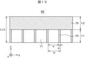
クロスルーバは一体型で形成することも出来る。図12は一体型クロスルーバ80の斜視図である。図12において、第1ルーバと第2ルーバが一体型として形成されている他は、図8、図9で説明したのと同様である。すなわち、下側のルーバは、ルーバブレード70がx方向に延在し、上側のルーバは、ルーバブレード70がy方向に延在している。ルーバブレード70とルーバブレード70の間には透明樹脂71が存在している。The cross louvers can also be formed as an integral unit. Figure 12 is a perspective view of an
図13は図12をA方向から視た側面図である。上側ルーバと下側ルーバの基本的な構造は図8で説明したのと同様である。図13では、下側のルーバの高さはt1で上側のルーバの高さはt2である。t1とt2は同じでもよい。x方向の配光角とy方向の配光角を変えたい場合は、t1とt2を変えればよい。Figure 13 is a side view of Figure 12 viewed from direction A. The basic structure of the upper and lower louvers is the same as that explained in Figure 8. In Figure 13, the height of the lower louver is t1 and the height of the upper louver is t2. t1 and t2 may be the same. If you wish to change the light distribution angle in the x direction and the light distribution angle in the y direction, you can simply change t1 and t2.
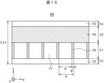
図14はクロスルーバの上下にルーバカバー72を形成した場合である。ルーバカバー72は、クロスルーバの機械的な強度が必要な場合等に用いられる。図15は図14をB方向から視た側面図である。ルーバカバー72は、例えばポリカーボネイトで形成され、厚さtcは、例えば0.2mm程度である。図15のその他の構成は、図13で説明したのと同様である。Figure 14 shows a case where louver covers 72 are formed above and below the cross louvers. Louver covers 72 are used when the mechanical strength of the cross louvers is required. Figure 15 is a side view of Figure 14 as viewed from direction B. The
図8乃至図15で説明したルーバはルーバブレード70とルーバブレード70の間に透明樹脂71が存在している構成である。透明樹脂71の屈折率nが大きいと、配光角も大きくなる。ルーバブレード70とルーバブレード70の間が空間であれば、配光角をより小さく出来る。図16乃び図17はその例である。図16において、左側は第1ルーバ50の平面図である、右側は第2ルーバ60の平面図である。第1ルーバ50と第2ルーバ60は、角度が90度回転しているだけで、同じ構造である。The louvers described in Figures 8 to 15 have a configuration in which
図16において、ルーバブレード70は黒色の樹脂でも金属でもよい。ルーバブレード70とルーバブレード70の間は空間75であり、樹脂は存在していない。ルーバブレード70がばらばらにならないように、ルーバ枠73が存在している。ルーバ枠73は、例えば、厚さ0.2mm程度のポリカーボネイトで形成してもよいし、金属で形成してもよい図16では、上下方向にのみルーバ枠73が形成されているが、ルーバ枠73は全周に形成してもよい。In FIG. 16, the
図17は図16のC-C断面図である。図17に示す矢印LLは光の経路を示している。図17は、ルーバブレード70とルーバブレード70の間は空間なので、屈折は生じない。ルーバ60から出射する光の配光角θは、(式2)によって表すことが出来る。図9と図17を比較すると、図17では、屈折率nの分、配光角θを小さくすることが出来る。Figure 17 is a cross-sectional view taken along the line CC of Figure 16. Arrow LL in Figure 17 indicates the path of light. In Figure 17, there is space between the
θ=2sin-1{sin(tan-1(a/t))} (式2)
図18は、クロスルーバ80を一体で形成する場合の斜視図である。図18は、ルーバブレード70を同一平面上に格子状に配置することによってクロスルーバの機能を1枚のシートで達成する構成である。図18では、各格子内は空間75となっている。図18における格子は、図16で説明したのと同様、金属、あるいは、黒色の樹脂で形成することが出来、ルーバブレード70の厚さ、高さ、ピッチ等は、必要な配向角によって変えればよい。例えば、ルーバの高さt、空間の幅a、ルーバブレードの厚さb等は、図9を参考に決めることが出来る。 θ=2sin-1{sin(tan-1(a/t))} (Formula 2)
Fig. 18 is a perspective view of a case where the
また、図18の格子のままでは形状が不安定である場合は、図16で説明したように、ポリカーボネイト等によるルーバ枠73を配置すればよい。図18における各格子内における光の経路、あるいは、配光角度は図17で説明したとおりである。なお、光の経路は(式2)で表すことが出来る。ところで、図18は、各格子内は空間75であるが、各格子内に透明樹脂を充填してもよい。この場合の光の経路は(式1)で表される。If the shape of the lattice in Figure 18 is unstable, a
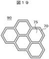
図19は、ルーバ90をハニカム構造で構成した例を示す平面図である。図19において、ハニカム構造は、黒色樹脂あるいは金属で形成されたルーバブレード70で形成され、各セルは空間75となっている。コリメート効果は(式2)と同じである。ハニカム構造は平面で、60度回転するごとに同じ構成が繰り返されるので、ルーバの回転方向の組み立て誤差が生じにくいという利点がある。また、後で説明する、プリズムシート24との干渉によるモアレも生じにくいという利点を有している。Figure 19 is a plan view showing an example in which louvers 90 are constructed with a honeycomb structure. In Figure 19, the honeycomb structure is formed with
図19におけるハニカム構造は、図16で説明したのと同様、金属、あるいは、黒色の樹脂で形成することが出来、ルーバブレード70の厚さ、高さ、ピッチ等は、必要な配向角によって変えればよい。例えば、ルーバの高さt、空間の幅a、ルーバブレード70の厚さb等は、図9を参考に決めることが出来る。The honeycomb structure in FIG. 19 can be formed from metal or black resin, as explained in FIG. 16, and the thickness, height, pitch, etc. of the
図19のハニカムルーバ90の各セル内は空間75であるが、各セル内に透明樹脂を充填することも出来る。この場合は、コリメート効果は(式1)で表すことが出来る。また、ルーバの強度を確保するために、必要に応じてルーバカバー72を用いてもよい。Each cell of the
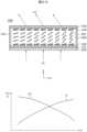
図6に示す実施例1の構成では、光をコリメートするために、逆プリズムシート24を用いている。逆プリズムシート24は、プリズム面が下側になっているプリズムシートである。図20はプリズムシート24の詳細図である。図20のプリズムシート24において、V溝によって形成されたプリズムアレイがy方向に延在し、x方向に配列している。なお、プリズムシート24は必要に応じて2枚使用してもよい。この場合は、プリズムアレイの延在方向を2枚のプリズムシートにおいて直角方向に配置する。In the configuration of Example 1 shown in FIG. 6, an
プリズムシート24の寸法例は次のとおりである。プリズムシート24の厚さtpは例えば0.125mm、V溝の深さVdは例えば0,075mm、頂角θpは例えば66度、ピッチppは、例えば0.1mmである。図20のプリズムシート24は、x方向に広がろうとする光を出射面方向、すなわち、z方向に集める作用をする。Example dimensions of the
図20に示すプリズムシート24では、微視的に視ると、横方向のピッチppによって縦縞が繰り返し現れる。したがって、例えば、図8の第2ルーバ60と干渉を生じてモアレを発生しやすい。これを防止するには、図21に示すように、例えば第2ルーバ60を平面方向にφだけ回転させればよい。φの値は例えば3度乃至4度、つまり、3度以上でよい。この場合、第1ルーバも同じようにφだけ回転する。When viewed microscopically, the
図20のプリズムシートにおけるプリズムアレイはy方向に延在しているが、プリズムアレイがx方向に延在する場合もある。この場合は、例えば図8の第1ルーバ50との干渉が問題となるが、上記の説明と同様にして対策することが出来る。なお、ルーバ50、60を回転させる代わりに、プリズムシートを回転させてもよい。The prism array in the prism sheet in Figure 20 extends in the y direction, but there are also cases where the prism array extends in the x direction. In this case, for example, interference with the
ところで、ルーバは、実施例2で説明する、液晶レンズの電極とも干渉を生じてモアレを発生する場合がある。この場合も、例えば、ルーバブレード70の延在方向を、液晶レンズの電極の延在方向と、平面で視て、3度乃至4度、つまり、3度以上回転させることによって、モアレを軽減することが出来る。あるいは、後で詳述するように、液晶レンズの電極の延在方向を同様な角度、回転させることによってモアレを軽減することが出来る。Incidentally, the louvers may also interfere with the electrodes of the liquid crystal lens, as described in Example 2, causing moire fringes. In this case, too, moire fringes can be reduced by rotating the extension direction of the
図22は実施例2による照明装置1000の分解斜視図である。図22が図6と異なる点は、図22では、図6における透明カバー30の代わりに液晶レンズ100を用いている点である。本明細書における液晶レンズ100は収束、発散のみでなく、光を偏向する作用(光の進行方向を変える作用)を持つものも含む。図22において、外枠20から遮光テープ26までの構成は図6と同じなので説明を省略する。つまり、図22の液晶レンズ100にはクロスルーバ50、60等によってコリメートされた光が入射する。Figure 22 is an exploded perspective view of a
図23は、液晶レンズの原理を示す断面図である。図23において、液晶層300の左側からコリメートされた光が入射している。図3におけるPは入射光の偏向方向の意味である。通常の光の偏向方向はランダム分布しているが、液晶は屈折率に異方性があるので、図23はP方向に偏向している光についての作用を示すものである。Figure 23 is a cross-sectional view showing the principle of a liquid crystal lens. In Figure 23, collimated light is incident from the left side of the
図23において、液晶層300には、電極によって液晶分子301が液晶層300の周辺に行くにしたがって、傾きが大きくなるように配向している。液晶分子301は細長い形状であり、液晶分子301の長軸方向の実効屈折率は、液晶分子301の短軸方向の実効屈折率よりも大きいので、液晶層300の周辺ほど屈折率が大きくなるため、凸レンズが形成される。図23における点線は光波面WFであり、fはレンズのフォーカス距離である。In FIG. 23, the
液晶は、屈折率に異方性があるので、レンズを形成するには、第1のレンズが作用する光の偏向方向と直角方向に偏向する光に作用する第2のレンズが必要になる。図24はこのレンズ構成を示す分解斜視図である。図24において、左側の平行四辺形は光の波面である。つまり、X方向とY方向に偏向した光が液晶層に入射する。第1液晶レンズ110はX偏光光に作用するレンズであり、第2レンズ120はY偏光光に作用するレンズである。Since liquid crystals have anisotropic refractive index, to form a lens, a second lens is required that acts on light polarized in a direction perpendicular to the direction of polarization of the light that the first lens acts on. Figure 24 is an exploded perspective view showing this lens configuration. In Figure 24, the parallelogram on the left is the wavefront of the light. In other words, light polarized in the X and Y directions enters the liquid crystal layer. The first
図24において、第1液晶レンズ110と第2液晶レンズ120では液晶分子301の初期配向方向が90度異なっている。液晶分子301の初期配向は、液晶レンズ内の配向膜の配向方向によって決定される。つまり、図24では、2枚の液晶レンズにおいて、光が入射する側の基板における配向膜の配向方向が互いに直角方向になっている。In FIG. 24, the initial alignment directions of the
図25は液晶レンズによって凹レンズを形成する場合である。図25において、波面WFが液晶層300に平行で、1方向に偏向した光が、左側から液晶層300に入射する。図25において、液晶層300における液晶分子301は、電極によって光軸付近において最も大きく配向され、周辺に行くにしたがって、配向角度が小さくなっている。このような液晶配向によるレンズ構成によって、液晶層300を通過した光の波面WFは図25の点線で示すような曲線になって凹レンズが形成される。なお、凹レンズの場合も、図24に示すように、2枚の液晶レンズが必要なことは同じである。Figure 25 shows the case where a concave lens is formed by a liquid crystal lens. In Figure 25, the wavefront WF is parallel to the
図26は液晶レンズによって、光を左方向に偏向する場合の原理を示す図である。図26において、上側の図は、液晶レンズ100の断面図である。液晶レンズ100の第1基板101の上に第1電極102が形成され、第2基板103の上に第2電極104が形成され、第1電極102と第2電極104の間に液晶層300が存在している。液晶層300はシール材105によって封止されている。図26では、液晶レンズを2枚使用する代わりに、偏光板250を用いているので、液晶レンズは1枚である。Figure 26 shows the principle of deflecting light to the left by a liquid crystal lens. In Figure 26, the upper diagram is a cross-sectional view of
図26の第1電極102と第2電極104の間に、図26の下側のグラフに示すように、電位差が左から右に大きくなるような電圧vを印加すると、液晶分子301の配向角度が場所ごとに変化し、液晶層300の実効複屈率Δnがグラフのように変化する。このような液晶層300の構成によって、液晶レンズ100に下側から入射したコリメート光LLは左方向に偏向されて出射することになる。When a voltage v is applied between the
図27は液晶レンズ100によって、光を右方向に偏向する場合の原理を示す図である。図27において、上側の図は、第1電極102と第2電極104の間の電圧のかけ方を除いて図26と同じである。図27の第1電極102と第2電極104の間に、図27の下側のグラフに示すように、左から右に電位差が小さくなるような電圧vを印加すると、液晶分子301の配向角度が場所ごとに変化し、液晶の実効複屈率Δnが、グラフのように変化する。このような液晶層300の構成によって、液晶レンズ100に入射したコリメート光LLは右方向に偏向されることになる。Figure 27 shows the principle of deflecting light to the right by the
図28は実際の液晶レンズの構成の第1の例を示す断面図である。図28において、第1基板101の上に第1電極102が配置し、第2基板103の上に第2電極104が配置し、第1基板101と第2基板103の間に液晶層300が挟持されている。第1電極102と第2電極104を覆って配向膜が形成されているが図28では省略されている。以下の図も同様である。配向膜にラビング処理等の配向処理を行うことによって液晶分子301の初期配向方向を決める。Figure 28 is a cross-sectional view showing a first example of the configuration of an actual liquid crystal lens. In Figure 28, a
図28では、第1基板101側の液晶分子301の初期配向方向と第2基板103側の液晶分子301の初期配向方向が90度となっており、いわゆるTN(Twisted Nematic)タイプの液晶レンズとなっている。第1電極102はx方向に延在し、第2電極104はy方向に延在している。ただし、液晶レンズ100の形成にはTNタイプタイプの液晶に限る必要はない。In FIG. 28, the initial alignment direction of the
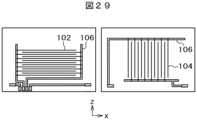
図29の左側の図は第1基板101に形成された第1電極102の平面図である。図29の右側の図は第2基板103に形成された第2電極104の平面図である。第1電極102はx方向に延在しており、第2電極104はy方向に延在している。第1電極102と第2電極104の交点において、液晶分子301が電圧に従って配向する。つまり、第1電極102と第2電極104への電圧の印加方法によって種々の液晶レンズの機能を発揮させることが出来る。The diagram on the left side of FIG. 29 is a plan view of the
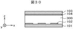
図30は実際の液晶レンズ100の構成の第2の例を示す断面図である。図28において、第1基板101の上にストライプ状の第1電極102が配置し、第2基板103の上に平面状の第2電極104が配置し、第1基板101と第2基板103の間に液晶層300が挟持されている。図31の左側の図は第1基板101に形成された第1電極102の平面図であり、第1電極はx方向に延在している。図31の右側の図は第2基板103に形成された第2電極104の平面図であり、第2電極104は平面状である。第2の例も、第1電極102と第2電極104の間に印加される電圧によって種々の液晶レンズの機能を発揮させることが出来る。Figure 30 is a cross-sectional view showing a second example of the configuration of an actual
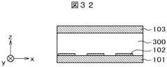
図32は実際の液晶レンズ100の構成の第3の例を示す断面図である。図32において、第1基板101の上にストライプ状の第1電極102が配置し、第2基板103には電極は形成されていない。図33の左側の図は第1基板101に形成された第1電極102の平面図であり、第1電極102はx方向に延在している。図33の右側の図は第2基板103だけが描かれており、第2電極は存在していない。Figure 32 is a cross-sectional view showing a third example of the configuration of an actual
第3の例は、第1基板101に形成された第1電極102のみによって液晶を駆動する、横電界方式の液晶レンズである。すなわち、隣接するストライプ状の第1電極102間の電位差によって液晶分子301が配向し、これによってレンズが形成される。第1電極102のストライプ電極間における電圧を種々変化させることによって、種々のレンズを構成することが出来る。The third example is a horizontal electric field type liquid crystal lens in which the liquid crystal is driven only by the
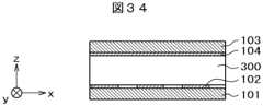
図34は実際の液晶レンズ100の構成の第4の例を示す断面図である。図34において、第1基板101の上に同心円状の第1電極102が配置し、第2基板102の上に平面状の第2電極104が配置し、第1基板101と第2基板103の間に液晶層300が挟持されている。図35の左側の図は第1基板100に形成された第1電極102の平面図である。第1電極102は同心円状の円となっている。円状の各電極には電圧を印加するための引き出し電極106が接続されている。Figure 34 is a cross-sectional view showing a fourth example of the configuration of an actual
図35において、第1電極102と第2電極104間の電圧を変化させることによって種々の強度のレンズを形成することができる。第4の例は、第1電極102が同心円で形成されているので、円形のレンズを容易に形成できるという特徴を有している。In FIG. 35, lenses of various strengths can be formed by changing the voltage between the
図28乃至図35はいずれも1枚分の液晶レンズの構造である。しかし、液晶は、1方向の偏光光のみ制御できるので、実際の液晶レンズでは、2枚の液晶レンズを組として使用する必要がある。図36は、第1の液晶レンズ110と第2の液晶レンズ120を、接着材200を用いて重ね合わせた場合の断面図である。All of Figures 28 to 35 show the structure of a single liquid crystal lens. However, since liquid crystal can only control polarized light in one direction, an actual liquid crystal lens must be used in a set of two liquid crystal lenses. Figure 36 is a cross-sectional view of a first
図36において、第1液晶レンズ110はTN液晶であって、第1基板101の上に第1電極102が形成され、第2基板103の上に第2電極104が形成され、第1基板101と第2基板103の間に液晶層300が挟持されている構成である。第2液晶レンズ120も同じ構造である。第1液晶レンズと第2液晶レンズの構造は同じであるが、第1液晶レンズ110における第1基板101の配向膜の配光方向ALと、第2液晶レンズ120における第1基板101の配向膜の配光方向ALが90度方向に交差している。つまり、入射光の第1の方向に偏光した偏光光に対して第1の液晶レンズ110が作用し、入射光の第1の方向と直角方向の第2の方向に偏光した偏光光に対して第2の液晶レンズ120が作用する。In FIG. 36, the first
2枚の液晶レンズだけではレンズ作用、あるいは、偏向作用が十分でない場合、液晶レンズを4枚用いればよい。図37は4枚の液晶レンズを接着材200によって組み合わせた例である。図37において、下側から第1液晶レンズ110、第2液晶レンズ120、第3液晶レンズ130、第4液晶レンズ140というように積層されている。第1液晶レンズ110と第2液晶レンズ120の構成は図36で説明したとおりである。第3液晶レンズ130と第4液晶レンズ140も第1液晶レンズ110あるいは第2液晶レンズ120と同じである。When two liquid crystal lenses alone do not provide sufficient lens action or deflection action, four liquid crystal lenses may be used. Figure 37 shows an example in which four liquid crystal lenses are combined with
図37において、第1液晶レンズ110の第1基板101に形成された配向膜の配向方向ALと第2液晶レンズ120の第1基板101に形成された配向膜の配光方向ALは直角であり、第3液晶レンズ130の第1基板101に形成された配向膜の配向方向ALと第4液晶レンズ140の第1基板101に形成された配向膜の配光方向ALは直角である。In FIG. 37, the orientation direction AL of the orientation film formed on the
なお、第1液晶レンズ乃至第4液晶レンズの配向膜の配向方向は、図37以外の組み合わせも可能である。また、各液晶レンズはTN液晶に限定する必要もない。The orientation directions of the alignment films of the first to fourth liquid crystal lenses can be other than those shown in FIG. 37. Also, each liquid crystal lens does not need to be limited to TN liquid crystal.
図38は、液晶レンズ100を1枚で済ませたい場合の構成である。図38において、第1液晶レンズ110の下に偏光板250が貼り付けられている。第1液晶レンズ110の構造と作用は、図28乃至図31等で説明したとおりである。液晶は、特定の偏向方向の光のみに作用するので、偏向光を第1液晶レンズ110に入射する必要がある。Figure 38 shows a configuration in which only one
図38は、偏光板250を液晶レンズ110の第1基板101に配置することによって、液晶によって制御可能な偏光光を第1液晶レンズ110に入射させている。しかし、偏光板250を用いると、偏光板250の透過軸方向と直角な方向に偏光する光は透過できない。そこで、偏光板250を透過できない光をプリズムシート側に反射し、プリズムシート側で再び反射させることによって光の偏光軸を回転し、再利用することが出来るような、偏向反射板を用いることによって、光の利用効率を上げることが出来る。In Figure 38, polarized light that can be controlled by liquid crystal is made to enter the first
図39は、図28に示す液晶レンズの斜視図である。第1基板101に第1電極102がy方向に延在し、x方向に配列している。第2基板103に第2電極104がx方向に延在し、y方向に配列している。第1基板101と第2基板103を重ね合わせると、電極形状は、平面で視て井桁状に見える。Figure 39 is a perspective view of the liquid crystal lens shown in Figure 28. On the
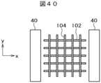
図40は、図22の照明装置において、液晶レンズ100の電極とLEDアレイ40のみを取り出した平面図である。液晶レンズ100は図28の構成を用いている。液晶レンズ100に形成された電極はITO等の透明電極で形成される場合が多いが、透明電極であっても透過率は100%ではないので、規則的な明暗が発生する。そうすると、この規則的な明暗とクロスルーバ50,60との干渉が生じ、モアレが発生する。Figure 40 is a plan view of only the electrodes of the
図41は、モアレを対策した構成を示す平面図である。図41において、井桁構成の電極102、104を、平面で視て、45度回転させている。これによって、モアレを抑止しすることが出来る。回転する角度φは3度乃至4度でもモアレに対しては大きな効果がある。Figure 41 is a plan view showing a configuration that counters moire. In Figure 41, the
図42は、液晶レンズを2枚使用した場合の例である。第1の液晶レンズに形成された井桁構造の電極と第2の液晶レンズに形成された井桁構造の電極が、平面で視て、45度の角度で重なっている。図42のバリエーションとして、第1の液晶レンズに形成された井桁構造の電極をx方向に対して22.5度回転させ、かつ、第2液晶レンズに形成された井桁構造の電極を、さらに45度回転させた構造とすれば、より一層、モアレが改善される。Figure 42 shows an example in which two liquid crystal lenses are used. The lattice-structured electrodes formed on the first liquid crystal lens and the lattice-structured electrodes formed on the second liquid crystal lens overlap at a 45-degree angle in a plan view. As a variation of Figure 42, if the lattice-structured electrodes formed on the first liquid crystal lens are rotated 22.5 degrees in the x direction and the lattice-structured electrodes formed on the second liquid crystal lens are rotated a further 45 degrees, moire can be further improved.
このように、液晶レンズ100に形成される電極を種々の角度で回転させることによって、クロスルーバ50、60との干渉を防止することが出来る。以上で説明した液晶レンズ100は図28及び図29に示す液晶レンズのみでなく、図30及び図31に示す液晶レンズの他、種々の液晶レンズに適用することが出来る。なお、液晶レンズの電極を回転するのでなく、クロスルーバ50、60を平面方向で回転させても同様な効果を得ることが出来る。In this way, by rotating the electrodes formed on the
ところで、液晶レンズの第1基板101の第1電極102を、図34及び図35に示すような、同心円状の電極とすれば、クロスルーバとの干渉によるモアレは発生しにくい。つまり、モアレという点においては、同心円状の電極を有する液晶レンズはクロスルーバとの組み合わせに適している。Incidentally, if the
図43は、液晶レンズ100の構成に対し、平面方向において特性の異なる複数の領域を形成した構成を示す平面図である。照明装置からの出射光を単なる光スポットではなく、輝度分布を持ったスポット、あるいは、スポット形状を変化させたい場合等がある。液晶レンズ100に、平面で視て、特性の異なる複数の領域を形成することによって、このような要求を満たすことが出来る場合がある。図43における領域R1と領域R2とでは、液晶レンズを構成する電極形状を変化させ、領域毎に液晶レンズの特性を変えている。これに加えて、電極に加わる電圧を制御することによってより細かな制御をおこなうことが出来る。Figure 43 is a plan view showing a configuration in which multiple regions with different characteristics are formed in the planar direction of the
1…放物線ミラー、 2…LED、 3…LED基板、 4…ヒートシンク、 20…外枠、 21…樹脂枠、 22…反射シート、 23…導光板、 24…プリズムシート、 25…スペーサ、 26…遮光テープ、 30…カバー、 31…出射領域、 32…コリメート光、 40…LEDアレイ、 41…LED、 42…LED基板、 50…第1ルーバ、 60…第2ルーバ、 70…ルーバブレード、 71…透明樹脂、 72…ルーバカバー、 73…ルーバ枠、 75…空間、 80…クロスルーバ、 90…ハニカムルーバ、 100…液晶レンズ、 101…第1基板、 102…第1電極、 103…第2基板、 104…第2電極、 105…シール材、 106…引き出し線、 110…第1液晶レンズ、 120…第2液晶レンズ、 130…第3液晶レンズ、 140…第4液晶レンズ、 200…接着材、 250…偏光板、 1000…照明装置、 2000…照明装置、 AL…配向方向、 LL…光、 Lx…漏れ光、 Ly…漏れ光、 R1…第1領域、 R2…第2領域、 521…第4電極1...parabolic mirror, 2...LED, 3...LED substrate, 4...heat sink, 20...outer frame, 21...resin frame, 22...reflective sheet, 23...light guide plate, 24...prism sheet, 25...spacer, 26...light shielding tape, 30...cover, 31...emission area, 32...collimated light, 40...LED array, 41...LED, 42...LED substrate, 50...first louver, 60...second louver, 70...louver blade, 71...transparent resin, 72...louver cover, 73...louver frame, 75...space, 80...cross louver, 90...honeycomb louver, 100...liquid crystal lens, 101...first substrate, 102...first electrode, 103...second substrate, 104...second electrode, 105...sealing material, 106...drawing wire, 110...first liquid crystal lens, 120...second liquid crystal lens, 130...third liquid crystal lens, 140...fourth liquid crystal lens, 200...adhesive, 250...polarizing plate, 1000...lighting device, 2000...lighting device, AL...alignment direction, LL...light, Lx...leakage light, Ly...leakage light, R1...first region, R2...second region, 521...fourth electrode
Claims (11)
Translated fromJapanese前記プリズムシートの上には、第1の方向に延在する第1ルーバと、前記第1の方向と直角方向の第2の方向に延在する第2ルーバとが積層されて配置し、
前記第2ルーバの上に液晶レンズが配置し、
前記液晶レンズは、前記第1の方向に延在する第1電極を備える第1基板と、前記第2の方向に延在する第2電極を備える第2基板と、前記第1基板と前記第2基板との間に配置された液晶層とを備え、
前記液晶レンズには前記第1ルーバと前記第2ルーバとによってコリメートされた光が入射することを特徴とする照明装置。 An illumination device comprising: an LED disposed on a side surface of a light guide plate;the light guide plate having a main surface for emitting light from the LED that is incident from the side surface; and a prism sheet disposedonthe main surface of the light guide plate,
a first louver extending in a first direction and a second louver extending ina second direction perpendicular to the first direction are stacked on the prism sheet;
A liquid crystal lens is disposed on the second louver;
the liquid crystal lens comprises a first substrate having a first electrode extending in the first direction, a second substrate having a second electrode extending in the second direction, and a liquid crystal layer disposed between the first substrate and the second substrate;
a liquid crystal lens that receives light collimated by the first louver and the second louver ;
前記第1の厚さと前記第2の厚さは異なることを特徴とする請求項1に記載の照明装置。 the first louver has a first thickness along an optical axis and the second louver has a second thickness along the optical axis;
The illumination device of claim 1 , wherein the first thickness and the second thickness are different.
Priority Applications (5)
| Application Number | Priority Date | Filing Date | Title |
|---|---|---|---|
| JP2021024054AJP7637528B2 (en) | 2021-02-18 | 2021-02-18 | Lighting equipment |
| CN202111551985.3ACN114963128A (en) | 2021-02-18 | 2021-12-17 | Lighting device |
| US17/569,525US11655944B2 (en) | 2021-02-18 | 2022-01-06 | Lighting device |
| DE102022201025.6ADE102022201025A1 (en) | 2021-02-18 | 2022-02-01 | lighting device |
| US18/136,881US11852303B2 (en) | 2021-02-18 | 2023-04-20 | Lighting device |
Applications Claiming Priority (1)
| Application Number | Priority Date | Filing Date | Title |
|---|---|---|---|
| JP2021024054AJP7637528B2 (en) | 2021-02-18 | 2021-02-18 | Lighting equipment |
Publications (2)
| Publication Number | Publication Date |
|---|---|
| JP2022126144A JP2022126144A (en) | 2022-08-30 |
| JP7637528B2true JP7637528B2 (en) | 2025-02-28 |
Family
ID=82610975
Family Applications (1)
| Application Number | Title | Priority Date | Filing Date |
|---|---|---|---|
| JP2021024054AActiveJP7637528B2 (en) | 2021-02-18 | 2021-02-18 | Lighting equipment |
Country Status (4)
| Country | Link |
|---|---|
| US (2) | US11655944B2 (en) |
| JP (1) | JP7637528B2 (en) |
| CN (1) | CN114963128A (en) |
| DE (1) | DE102022201025A1 (en) |
Families Citing this family (2)
| Publication number | Priority date | Publication date | Assignee | Title |
|---|---|---|---|---|
| EP4307037A4 (en) | 2021-03-12 | 2025-06-11 | Japan Display Inc. | LIQUID CRYSTAL DEVICE |
| KR102852912B1 (en)* | 2021-08-23 | 2025-09-02 | 가부시키가이샤 재팬 디스프레이 | Liquid crystal light control elements and lighting devices |
Citations (7)
| Publication number | Priority date | Publication date | Assignee | Title |
|---|---|---|---|---|
| JP2007003951A (en) | 2005-06-24 | 2007-01-11 | Nec Corp | Optical member, light source device, display device, and terminal device |
| JP2007212507A (en) | 2006-02-07 | 2007-08-23 | Shin Etsu Polymer Co Ltd | Peep prevention object |
| JP2007279424A (en) | 2006-04-07 | 2007-10-25 | Three M Innovative Properties Co | Privacy filter sheet and display device containing the same |
| WO2012099127A1 (en) | 2011-01-17 | 2012-07-26 | 株式会社オルタステクノロジー | Liquid crystal lens, liquid crystal lens drive method, lens unit, camera module, and capsule-type medical apparatus |
| WO2014196125A1 (en) | 2013-06-05 | 2014-12-11 | パナソニックIpマネジメント株式会社 | Image display device and liquid crystal lens |
| JP2016057541A (en) | 2014-09-11 | 2016-04-21 | パナソニックIpマネジメント株式会社 | Liquid crystal lens, lighting device and lighting system |
| JP2018045096A (en) | 2016-09-14 | 2018-03-22 | 株式会社ジャパンディスプレイ | Display device |
Family Cites Families (16)
| Publication number | Priority date | Publication date | Assignee | Title |
|---|---|---|---|---|
| JPH0766119B2 (en)* | 1985-09-06 | 1995-07-19 | セイコーエプソン株式会社 | Transmissive liquid crystal display device |
| JP2007052323A (en)* | 2005-08-19 | 2007-03-01 | Sanyo Epson Imaging Devices Corp | Electrooptical device and electronic equipment |
| JP4822535B2 (en)* | 2005-12-22 | 2011-11-24 | Nltテクノロジー株式会社 | Liquid crystal display device and terminal device using the same |
| CN101473168B (en)* | 2006-06-20 | 2012-04-18 | 日本电气株式会社 | Illuminating apparatus, illuminating method and display apparatus |
| JP2008089728A (en)* | 2006-09-29 | 2008-04-17 | Nec Lcd Technologies Ltd | OPTICAL ELEMENT, LIGHTING DEVICE, DISPLAY DEVICE, AND ELECTRONIC DEVICE USING THE SAME |
| JP2009128555A (en)* | 2007-11-22 | 2009-06-11 | Citizen Electronics Co Ltd | Liquid crystal lens |
| US9041881B2 (en)* | 2009-03-27 | 2015-05-26 | Nitto Denko Corporation | Liquid crystal display device |
| JP2012069409A (en) | 2010-09-24 | 2012-04-05 | Panasonic Corp | Lighting fixture |
| CN102231032B (en)* | 2011-05-20 | 2013-07-10 | 深圳超多维光电子有限公司 | Touch-type liquid crystal lens and driving method thereof, three-dimensional display device and computer system |
| CN102253562B (en)* | 2011-07-13 | 2014-11-26 | 深圳超多维光电子有限公司 | Stereo display device and liquid crystal lens thereof |
| EP2863105A4 (en)* | 2012-06-13 | 2015-05-06 | Citizen Electronics | Planar illumination device and display device having planar illumination device |
| CN104950544A (en)* | 2015-07-30 | 2015-09-30 | 重庆卓美华视光电有限公司 | Naked eye 3D display module |
| CN106154682A (en)* | 2016-08-30 | 2016-11-23 | 京东方科技集团股份有限公司 | A kind of display device |
| KR102485634B1 (en)* | 2016-09-09 | 2023-01-05 | 엘지디스플레이 주식회사 | Liquid crystal display device |
| CN106547048B (en)* | 2017-02-10 | 2019-08-06 | 京东方科技集团股份有限公司 | Light guide device and manufacturing method thereof, backlight module and display device |
| US11204458B2 (en)* | 2018-11-12 | 2021-12-21 | S.V.V. Technology Innovations, Inc. | Wide-area solid-state illumination devices and systems employing sheet-form light guides and method of making the same |
- 2021
- 2021-02-18JPJP2021024054Apatent/JP7637528B2/enactiveActive
- 2021-12-17CNCN202111551985.3Apatent/CN114963128A/enactivePending
- 2022
- 2022-01-06USUS17/569,525patent/US11655944B2/enactiveActive
- 2022-02-01DEDE102022201025.6Apatent/DE102022201025A1/enactivePending
- 2023
- 2023-04-20USUS18/136,881patent/US11852303B2/enactiveActive
Patent Citations (7)
| Publication number | Priority date | Publication date | Assignee | Title |
|---|---|---|---|---|
| JP2007003951A (en) | 2005-06-24 | 2007-01-11 | Nec Corp | Optical member, light source device, display device, and terminal device |
| JP2007212507A (en) | 2006-02-07 | 2007-08-23 | Shin Etsu Polymer Co Ltd | Peep prevention object |
| JP2007279424A (en) | 2006-04-07 | 2007-10-25 | Three M Innovative Properties Co | Privacy filter sheet and display device containing the same |
| WO2012099127A1 (en) | 2011-01-17 | 2012-07-26 | 株式会社オルタステクノロジー | Liquid crystal lens, liquid crystal lens drive method, lens unit, camera module, and capsule-type medical apparatus |
| WO2014196125A1 (en) | 2013-06-05 | 2014-12-11 | パナソニックIpマネジメント株式会社 | Image display device and liquid crystal lens |
| JP2016057541A (en) | 2014-09-11 | 2016-04-21 | パナソニックIpマネジメント株式会社 | Liquid crystal lens, lighting device and lighting system |
| JP2018045096A (en) | 2016-09-14 | 2018-03-22 | 株式会社ジャパンディスプレイ | Display device |
Also Published As
| Publication number | Publication date |
|---|---|
| DE102022201025A1 (en) | 2022-08-18 |
| US20220260217A1 (en) | 2022-08-18 |
| US20230258304A1 (en) | 2023-08-17 |
| CN114963128A (en) | 2022-08-30 |
| US11655944B2 (en) | 2023-05-23 |
| US11852303B2 (en) | 2023-12-26 |
| JP2022126144A (en) | 2022-08-30 |
Similar Documents
| Publication | Publication Date | Title |
|---|---|---|
| CN212160232U (en) | Head-up display system | |
| CN108646338B (en) | A kind of backlight module and display device | |
| CN101382693B (en) | Liquid crystal display device | |
| KR102482891B1 (en) | Complex optical sheet, liquid crystal display using the same and method of manufacturing the same | |
| US11852303B2 (en) | Lighting device | |
| WO2004111532A1 (en) | Planar light source device and display device using the same | |
| CN113531487B (en) | lighting device | |
| CN111796348A (en) | Visual angle diffusion film and display panel | |
| KR102081724B1 (en) | Display device having back light unit | |
| JP5724533B2 (en) | Optical module and display device | |
| KR102592717B1 (en) | Optical film and display device having the same | |
| CN111796349A (en) | Visual angle diffusion film and display panel | |
| US10534126B2 (en) | Lighting device and display device | |
| JP4848404B2 (en) | Liquid crystal display element and liquid crystal display device | |
| WO2021199653A1 (en) | Illumination device | |
| US9813696B2 (en) | Stereoscopic image display device | |
| JP2021150016A (en) | Lamp unit, vehicular lighting fixture system | |
| KR101830779B1 (en) | Reflective display device using polymer dispersed liquid crystal | |
| JP2012204139A (en) | Backlight and display device | |
| JP2013020932A (en) | Optical module and display device | |
| US11828454B2 (en) | Lighting device | |
| JP2023128766A (en) | Lighting device | |
| KR20250008848A (en) | Fresnel lens and image generating device having the same | |
| KR20110049732A (en) | New Turning Film for Liquid Crystal Display | |
| KR20140040558A (en) | Member for controlling luminous flux, light emitting device and display device having the same |
Legal Events
| Date | Code | Title | Description |
|---|---|---|---|
| A621 | Written request for application examination | Free format text:JAPANESE INTERMEDIATE CODE: A621 Effective date:20240208 | |
| A977 | Report on retrieval | Free format text:JAPANESE INTERMEDIATE CODE: A971007 Effective date:20240731 | |
| A131 | Notification of reasons for refusal | Free format text:JAPANESE INTERMEDIATE CODE: A131 Effective date:20240806 | |
| A521 | Request for written amendment filed | Free format text:JAPANESE INTERMEDIATE CODE: A523 Effective date:20241003 | |
| TRDD | Decision of grant or rejection written | ||
| A01 | Written decision to grant a patent or to grant a registration (utility model) | Free format text:JAPANESE INTERMEDIATE CODE: A01 Effective date:20250128 | |
| A61 | First payment of annual fees (during grant procedure) | Free format text:JAPANESE INTERMEDIATE CODE: A61 Effective date:20250217 | |
| R150 | Certificate of patent or registration of utility model | Ref document number:7637528 Country of ref document:JP Free format text:JAPANESE INTERMEDIATE CODE: R150 |