JP7635755B2 - Biological Devices - Google Patents
Biological DevicesDownload PDFInfo
- Publication number
- JP7635755B2 JP7635755B2JP2022099118AJP2022099118AJP7635755B2JP 7635755 B2JP7635755 B2JP 7635755B2JP 2022099118 AJP2022099118 AJP 2022099118AJP 2022099118 AJP2022099118 AJP 2022099118AJP 7635755 B2JP7635755 B2JP 7635755B2
- Authority
- JP
- Japan
- Prior art keywords
- case
- gas
- insulating sheet
- communication hole
- liquid separator
- Prior art date
- Legal status (The legal status is an assumption and is not a legal conclusion. Google has not performed a legal analysis and makes no representation as to the accuracy of the status listed.)
- Active
Links
Images


Classifications
- A—HUMAN NECESSITIES
- A61—MEDICAL OR VETERINARY SCIENCE; HYGIENE
- A61B—DIAGNOSIS; SURGERY; IDENTIFICATION
- A61B5/00—Measuring for diagnostic purposes; Identification of persons
- A61B5/68—Arrangements of detecting, measuring or recording means, e.g. sensors, in relation to patient
- A61B5/6801—Arrangements of detecting, measuring or recording means, e.g. sensors, in relation to patient specially adapted to be attached to or worn on the body surface
- B—PERFORMING OPERATIONS; TRANSPORTING
- B01—PHYSICAL OR CHEMICAL PROCESSES OR APPARATUS IN GENERAL
- B01D—SEPARATION
- B01D39/00—Filtering material for liquid or gaseous fluids
- B01D39/14—Other self-supporting filtering material ; Other filtering material
- B01D39/16—Other self-supporting filtering material ; Other filtering material of organic material, e.g. synthetic fibres
- G—PHYSICS
- G06—COMPUTING OR CALCULATING; COUNTING
- G06F—ELECTRIC DIGITAL DATA PROCESSING
- G06F1/00—Details not covered by groups G06F3/00 - G06F13/00 and G06F21/00
- G06F1/16—Constructional details or arrangements
- G06F1/1613—Constructional details or arrangements for portable computers
- G06F1/163—Wearable computers, e.g. on a belt
- G—PHYSICS
- G06—COMPUTING OR CALCULATING; COUNTING
- G06F—ELECTRIC DIGITAL DATA PROCESSING
- G06F1/00—Details not covered by groups G06F3/00 - G06F13/00 and G06F21/00
- G06F1/16—Constructional details or arrangements
- G06F1/1613—Constructional details or arrangements for portable computers
- G06F1/1633—Constructional details or arrangements of portable computers not specific to the type of enclosures covered by groups G06F1/1615 - G06F1/1626
- G06F1/1656—Details related to functional adaptations of the enclosure, e.g. to provide protection against EMI, shock, water, or to host detachable peripherals like a mouse or removable expansions units like PCMCIA cards, or to provide access to internal components for maintenance or to removable storage supports like CDs or DVDs, or to mechanically mount accessories
- H—ELECTRICITY
- H05—ELECTRIC TECHNIQUES NOT OTHERWISE PROVIDED FOR
- H05K—PRINTED CIRCUITS; CASINGS OR CONSTRUCTIONAL DETAILS OF ELECTRIC APPARATUS; MANUFACTURE OF ASSEMBLAGES OF ELECTRICAL COMPONENTS
- H05K5/00—Casings, cabinets or drawers for electric apparatus
- H05K5/0086—Casings, cabinets or drawers for electric apparatus portable, e.g. battery operated apparatus
- H—ELECTRICITY
- H05—ELECTRIC TECHNIQUES NOT OTHERWISE PROVIDED FOR
- H05K—PRINTED CIRCUITS; CASINGS OR CONSTRUCTIONAL DETAILS OF ELECTRIC APPARATUS; MANUFACTURE OF ASSEMBLAGES OF ELECTRICAL COMPONENTS
- H05K5/00—Casings, cabinets or drawers for electric apparatus
- H05K5/02—Details
- H05K5/0213—Venting apertures; Constructional details thereof
- H05K5/0215—Venting apertures; Constructional details thereof with semi-permeable membranes attached to casings
- A—HUMAN NECESSITIES
- A61—MEDICAL OR VETERINARY SCIENCE; HYGIENE
- A61B—DIAGNOSIS; SURGERY; IDENTIFICATION
- A61B2560/00—Constructional details of operational features of apparatus; Accessories for medical measuring apparatus
- A61B2560/04—Constructional details of apparatus
- A61B2560/0406—Constructional details of apparatus specially shaped apparatus housings
- A61B2560/0412—Low-profile patch shaped housings
- A—HUMAN NECESSITIES
- A61—MEDICAL OR VETERINARY SCIENCE; HYGIENE
- A61B—DIAGNOSIS; SURGERY; IDENTIFICATION
- A61B5/00—Measuring for diagnostic purposes; Identification of persons
- A61B5/01—Measuring temperature of body parts ; Diagnostic temperature sensing, e.g. for malignant or inflamed tissue
- A—HUMAN NECESSITIES
- A61—MEDICAL OR VETERINARY SCIENCE; HYGIENE
- A61B—DIAGNOSIS; SURGERY; IDENTIFICATION
- A61B5/00—Measuring for diagnostic purposes; Identification of persons
- A61B5/02—Detecting, measuring or recording for evaluating the cardiovascular system, e.g. pulse, heart rate, blood pressure or blood flow
- A61B5/024—Measuring pulse rate or heart rate
- A61B5/0245—Measuring pulse rate or heart rate by using sensing means generating electric signals, i.e. ECG signals
- A—HUMAN NECESSITIES
- A61—MEDICAL OR VETERINARY SCIENCE; HYGIENE
- A61B—DIAGNOSIS; SURGERY; IDENTIFICATION
- A61B5/00—Measuring for diagnostic purposes; Identification of persons
- A61B5/68—Arrangements of detecting, measuring or recording means, e.g. sensors, in relation to patient
- A61B5/6801—Arrangements of detecting, measuring or recording means, e.g. sensors, in relation to patient specially adapted to be attached to or worn on the body surface
- A61B5/683—Means for maintaining contact with the body
- A61B5/6832—Means for maintaining contact with the body using adhesives
- A61B5/6833—Adhesive patches
Landscapes
- Engineering & Computer Science (AREA)
- Health & Medical Sciences (AREA)
- Life Sciences & Earth Sciences (AREA)
- Computer Hardware Design (AREA)
- Physics & Mathematics (AREA)
- Theoretical Computer Science (AREA)
- Microelectronics & Electronic Packaging (AREA)
- General Engineering & Computer Science (AREA)
- Biomedical Technology (AREA)
- Veterinary Medicine (AREA)
- Heart & Thoracic Surgery (AREA)
- Medical Informatics (AREA)
- Molecular Biology (AREA)
- Surgery (AREA)
- Animal Behavior & Ethology (AREA)
- General Health & Medical Sciences (AREA)
- Public Health (AREA)
- Pathology (AREA)
- Biophysics (AREA)
- Chemical & Material Sciences (AREA)
- Chemical Kinetics & Catalysis (AREA)
- General Physics & Mathematics (AREA)
- Human Computer Interaction (AREA)
- Measuring And Recording Apparatus For Diagnosis (AREA)
- Casings For Electric Apparatus (AREA)
Description
Translated fromJapanese本発明は、生体デバイスに関する。The present invention relates to a biodevice.
特許文献1には、身体に装着される生体デバイスが記載されている。生体デバイスは、ケースと、電子ユニットと、気液分離シートと、を備えている。ケースは、ケースの内部空間とケースの外部空間とをつなぐ連通孔を有している。電子ユニットは、ケースに内蔵されている。電子ユニットは、電子回路、電源、及び電子基板を有している。気液分離シートは、ケースの連通孔を塞いでいる。気液分離シートは、気体を通す一方で、液体の水を通さない。
特許文献1に記載の生体デバイスは、ケースの内部に水が浸入することを防止できる一方で、ケース内外の絶縁性については特に考慮していない。ところで、ユーザの身体のうち生体デバイスが装着された箇所の近傍において、電気メスや除細動器など、放電する機器が使用されることがある。この場合、これらの機器から生体デバイスへと電気的衝撃が加わることがある。そのため、生体デバイスのケースの外部から生体デバイスのケースに内蔵される電子ユニットへと電流が流れる虞がある。While the biodevice described in
上記課題を解決するため、本開示の一態様は、連通孔を有し、身体に装着可能なケースと、前記ケースに内蔵される電子ユニットと、前記ケースに取り付けられる気液分離体と、前記ケース又は前記電子ユニットに取り付けられる絶縁シートと、を備え、前記連通孔は第1方向に連通して前記ケースの内部空間と外部空間とをつなぎ、前記第1方向において、前記気液分離体と前記絶縁シートとは離れて配置され、前記第1方向を向いて平面視したときに、前記気液分離体、前記電子ユニット、及び前記絶縁シートは、前記連通孔と重なっている生体デバイスである。In order to solve the above problem, one aspect of the present disclosure is a biodevice comprising a case having a communication hole and wearable on the body, an electronic unit built into the case, a gas-liquid separator attached to the case, and an insulating sheet attached to the case or the electronic unit, the communication hole communicates in a first direction to connect the internal space of the case to the external space, the gas-liquid separator and the insulating sheet are arranged apart in the first direction, and when viewed in a planar view facing the first direction, the gas-liquid separator, the electronic unit, and the insulating sheet overlap the communication hole.
上記構成によれば、第1方向を向いて平面視したときに、気液分離体、電子ユニット、及び絶縁シートは、連通孔と重なっている。そのため、連通孔を介して、ケースの外部から電子ユニットに向かって電流が流れることを、絶縁シートによって防止できる。According to the above configuration, when viewed in a plan view facing the first direction, the gas-liquid separator, the electronic unit, and the insulating sheet overlap with the communication hole. Therefore, the insulating sheet can prevent current from flowing from the outside of the case to the electronic unit through the communication hole.
上記課題を解決するため、本開示の一態様は、身体に装着可能なケースと、前記ケースの壁の一部を構成し、当該壁の厚み方向である第1方向において前記ケースの内部空間と外部空間とを気体が通過可能に配置される気液分離体と、前記ケースに内蔵される電子ユニットと、前記ケース又は前記電子ユニットに取り付けられる絶縁シートと、を備え、前記第1方向において、前記気液分離体と前記絶縁シートとは離れて配置され、前記第1方向を向いて平面視したときに、前記気液分離体、前記電子ユニット、及び前記絶縁シートは重なっている生体デバイスである。In order to solve the above problem, one aspect of the present disclosure is a biodevice comprising a case that can be worn on the body, a gas-liquid separator that constitutes part of a wall of the case and is arranged to allow gas to pass between an internal space and an external space of the case in a first direction that is the thickness direction of the wall, an electronic unit that is built into the case, and an insulating sheet that is attached to the case or the electronic unit, wherein the gas-liquid separator and the insulating sheet are arranged apart from each other in the first direction, and when viewed in a planar view facing the first direction, the gas-liquid separator, the electronic unit, and the insulating sheet are overlapped.
上記構成によれば、第1方向を向いて平面視したときに、気液分離体、電子ユニット、及び絶縁シートは、連通孔と重なっている。そのため、気液分離体を介してケースの外部から電子ユニットに向かって電流が流れることを、絶縁シートによって防止できる。According to the above configuration, when viewed in a plan view facing the first direction, the gas-liquid separator, the electronic unit, and the insulating sheet overlap with the communication hole. Therefore, the insulating sheet can prevent current from flowing from the outside of the case to the electronic unit via the gas-liquid separator.
ケースの外部から電子ユニットに向かって、電流が流れることを防止できる。This prevents current from flowing from the outside of the case to the electronic unit.
(第1実施形態)
以下、生体デバイスの第1実施形態について、図面を参照して説明する。なお、図面は、理解を容易にするために構成要素を拡大して示している場合がある。構成要素の寸法比率は実際のものと、又は別の図面中のものと異なる場合がある。 First Embodiment
Hereinafter, a first embodiment of the biodevice will be described with reference to the drawings. In addition, the drawings may show components enlarged for ease of understanding. The dimensional ratios of the components may differ from those in the actual drawings or from those in other drawings.
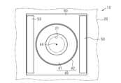
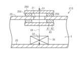
図1に示すように、生体デバイス10は、ケース20を備えている。ケース20は、身体に装着可能となっている。図2に示すように、ケース20は、内部空間Sを区画している。ケース20の材質は、例えば、合成樹脂である。そのため、ケース20は、身体の皮膚等に張り付けた際に、皮膚の動きに追従できる程度に弾性変形する。As shown in FIG. 1, the
ケース20は、円形状の連通孔21を有している。連通孔21は、内部空間Sとケース20の外部空間とを繋いでいる。連通孔21は、ケース20のうち、皮膚に張り付けられる面とは異なる面に開口している。そのため、生体デバイス10を身体に装着した場合でも、連通孔21は、身体によって塞がれない。The
なお、連通孔21の開口する方向に沿うとともに、連通孔21の開口中心を通る軸を、仮想軸AXとする。そして、仮想軸AXに沿う方向のうち、内部空間Sからケース20の外部空間に向かう方向を第1方向D1とする。また、仮想軸AXに沿う方向のうち、第1方向D1と反対方向を第2方向D2とする。つまり、連通孔21は、第1方向D1に連通してケース20の内部空間Sとケース20の外部空間とをつないでいる。The axis that runs along the direction in which the
生体デバイス10は、電子ユニット30を備えている。電子ユニット30は、内部空間S内に位置している。そのため、電子ユニット30は、ケース20に内蔵されている。電子ユニット30は、例えば、電子回路、電源及び電子基板を有している。特に、本実施形態では、電子ユニット30は、温度センサを有している。つまり、生体デバイス10は、温度センサによって、身体の温度を検出する生体センサとなっている。The
電子ユニット30は、連通孔21の開口する方向を向いて平面視したときに、連通孔21と重なる箇所に位置している。具体的には、電子ユニット30は、仮想軸AX上に位置している。また、連通孔21の開口する方向を向いて平面したときに、電子ユニット30は、連通孔21の全域と重なっている。When viewed in a plan view facing the direction in which the
生体デバイス10は、気液分離体40を備えている。気液分離体40は、気体を通し、且つ液体の水を通さない。具体的には、気液分離体40の材質は、ポリテトラフルオロエチレンである。また、気液分離体40の構造は、多孔質構造となっている。本明細書における、液体の水を通さないとは、0.3気圧の状態で液体の水を通さないことをいう。なお、本実施形態では、気液分離体40の耐水度は、200kPaである。本実施形態では、気液分離体40は多孔質構造であるため、外部から加わる圧力が耐水度を超えれば水を通す。The
気液分離体40は、ケース20に取り付けられている。気液分離体40は、連通孔21を塞いでいる。そのため、気液分離体40は、連通孔21を介した水の出入りを塞いでいる。具体的には、気液分離体40は、第1スペーサ41と、気液分離シート42と、を有している。なお、図2では、第1スペーサ41及び気液分離シート42を別の部材として図示しているが、両者は、一体化した1つの部材として成形されることもある。The gas-
図1に示すように、第1スペーサ41は、円環状となっている。第1スペーサ41の内径は、連通孔21の直径よりも大きくなっている。そして、第2方向D2を向いて生体デバイス10を平面視したときに、第1スペーサ41は、連通孔21を外側から囲んでいる。第1スペーサ41は、ケース20の内面に、図示しない接着剤を介して取り付けられている。As shown in FIG. 1, the
図2に示すように、気液分離シート42は、第1スペーサ41の第2方向D2を向く面に、図示しない接着剤を介して取り付けられている。図1に示すように、気液分離シート42は、円形状のシートとなっている。気液分離シート42の直径は、連通孔21の直径よりも大きくなっている。そのため、第2方向D2を向いて生体デバイス10を平面視したときに、気液分離シート42の面積は、連通孔21の面積よりも大きくなっている。また、第2方向D2を向いて生体デバイス10を平面視したときに、気液分離シート42は、連通孔21のすべての範囲と重なっている。As shown in FIG. 2, the gas-
上記の構造により、気液分離体40は、ケース20の内部空間Sを、気液分離体40に対して電子ユニット30が存在する側の空間と、電子ユニット30が存在しない側の空間と、に隔てている。そして、気液分離体40は、連通孔21を介して、ケース20の内部空間Sのうち気液分離体40よりも電子ユニット30が存在する側の空間に、液体の水が入り込むことを防止している。このように、気液分離体40は、液体の水が内部空間Sに入り込めないように、連通孔21を塞いでいる。With the above structure, the gas-
生体デバイス10は、2つの第2スペーサ50と、絶縁シート60と、を備えている。第2スペーサ50は、ケース20の内面と絶縁シート60との間に介在している。各第2スペーサ50の材質は、例えばポリエチレンテレフタラートである。つまり、各第2スペーサ50は、気体を通さない材質である。そして、各第2スペーサ50の材質は、電気を通さない絶縁体である。The
各第2スペーサ50の仮想軸AXに沿う方向の寸法は、気液分離体40における仮想軸AXに沿う方向の最大寸法よりも大きくなっている。第2方向D2を向いて生体デバイス10を平面視したときに、2つの第2スペーサ50は、連通孔21を挟んで両側に位置している。そのため、2つの第2スペーサ50は、第1方向D1を向いて平面視したときに、連通孔21を挟むように配置されている。また、2つの第2スペーサ50は、互いに平行の位置関係である。その結果として、2つの第2スペーサ50の間には隙間が生じている。つまり、2つの第2スペーサ50は、第2方向D2を向いて生体デバイス10を平面視したときに、連通孔21を部分的に取り囲んでいる。各第2スペーサ50は、図示しない接着剤によってケース20の内面に取り付けられている。The dimension of each
なお、第2スペーサ50が連通孔21を部分的に取り囲んでいるとは、連通孔21が第2スペーサ50によって、完全に囲まれていない状態を指す。つまり、第2方向D2を向いて生体デバイス10を平面視したときに、連通孔21から、第2スペーサ50を跨がずに、第2スペーサ50よりも外側の空間へと至る通路がある場合、第2スペーサ50が連通孔21を部分的に取り囲んでいるという。The
絶縁シート60は、第2スペーサ50の第2方向D2を向く面に、図示しない接着剤を介して取り付けられている。そのため、絶縁シート60は、第2スペーサ50を介して、ケース20に取り付けられている。また、絶縁シート60は、仮想軸AXに沿う方向において連通孔21から離れた箇所に位置している。さらに、絶縁シート60は、仮想軸AXに沿う方向において気液分離体40からも離れた箇所に位置している。すなわち、第1方向D1において、気液分離体40と絶縁シート60とは離れて配置されている。このように、生体デバイス10においては、第1方向D1に向かって、電子ユニット30、絶縁シート60、気液分離体40、連通孔21、の順に位置している。The insulating
絶縁シート60の材質は、絶縁体である。具体的には、絶縁シート60の材質は、ポリテトラフルオロエチレンである。また、絶縁シート60は、気体を通さない材質である。具体的には、絶縁シート60の構造は、気液分離体40のように多孔質構造となっていない。The material of the insulating
絶縁シート60は、四角形状のシートである。絶縁シート60の一辺の寸法は、各第2スペーサ50の長手方向の寸法よりも僅かに大きくなっている。第2方向D2を向いて生体デバイス10を平面視したときに、絶縁シート60の向かい合う2辺が、各第2スペーサ50の長手方向と平行になっている。第2方向D2を向いて生体デバイス10を平面視したときに、絶縁シート60は、連通孔21のすべての範囲と重なっている。このようにして、第1方向D1を向いて平面視したときに、気液分離体40、電子ユニット30、及び絶縁シート60は、連通孔21と重なっている。The insulating
また、第2方向D2を向いて生体デバイス10を平面視したときに、絶縁シート60の一辺の寸法は、連通孔21の直径よりも大きくなっている。そのため、第2方向D2を向いて生体デバイス10を平面視したときに、絶縁シート60の面積は、連通孔21の面積よりも大きくなっている。In addition, when the
さらに、第2方向D2を向いて生体デバイス10を平面視したときに、絶縁シート60の一辺の寸法は、気液分離シート42の直径よりも大きくなっている。そのため、第2方向D2を向いて生体デバイス10を平面視したときに、絶縁シート60の面積は、気液分離シート42の面積よりも大きくなっている。Furthermore, when the
また、第2方向D2を向いて生体デバイス10を平面視したときに絶縁シート60の外縁は、気液分離体40の外縁を取り囲んでいる。つまり、第2方向D2を向いて生体デバイス10を平面視したときに絶縁シート60の面積は、気液分離体40の面積よりも大きくなっている。In addition, when the
<第1実施形態の作用>
生体デバイス10は、身体に装着されることで使用される。生体デバイス10のケース20が皮膚等に張り付けられると、皮膚の動きに併せてケース20が変形する。ケース20が変形すると、ケース20の内部空間Sの容積が変わることで、内部空間Sとケース20の外部空間との間で、空気が出入りする。 <Operation of First Embodiment>
The
このとき、気液分離体40は気体を通すため、気液分離体40が連通孔21を介した気体の流通を遮断することはない。また、仮想軸AXに沿う方向において絶縁シート60は連通孔21から離れているので、絶縁シート60が連通孔21を介した気体の流通を遮断することはない。At this time, the gas-
<第1実施形態の効果>
(1-1)上記第1実施形態によれば、第1方向D1を向いて平面視したときに、気液分離体40、電子ユニット30、及び絶縁シート60は、連通孔21と重なっている。そのため、連通孔21を介してケース20の外部空間から電子ユニット30に向かって、電流が流れることを、絶縁シート60により防止できる。 Effects of the First Embodiment
(1-1) According to the first embodiment, when viewed in a plan view facing the first direction D1, the gas-
(1-2)上記第1実施形態によれば、第2方向D2を向いて生体デバイス10を平面視したときに、絶縁シート60は、連通孔21のすべての範囲と重なっている。そのため、連通孔21を介して、ケース20の外部空間から電子ユニット30に向かって、電流が流れることを確実に防止できる。(1-2) According to the first embodiment, when the
(1-3)上記第1実施形態によれば、第2スペーサ50が連通孔21を部分的に取り囲んでいる。そのため、第2スペーサ50が設けられていない箇所を介して気体の出入りが可能となるので、第2スペーサ50がケース20の外部空間と内部空間Sとの間での気体の出入りを過度に妨げない。(1-3) According to the first embodiment, the
(1-4)上記第1実施形態によれば、第2スペーサ50は、第1方向D1を向いて正面視したときに、連通孔21を挟むように配置されている。そのため、第2スペーサ50とケース20との間の隙間がつぶれるようにケース20が変形することを防止できる。(1-4) According to the first embodiment, the
(1-5)上記第1実施形態によれば、第2方向D2を向いて生体デバイス10を透視したときに、絶縁シート60の面積は、連通孔21の面積よりも大きくなっている。そのため、ケース20の外部空間から連通孔21を介して電子ユニット30へと向かう電流の経路を長くできる。これにより、ケース20の外部からの電流が電子ユニット30へ届くことを抑制できる。(1-5) According to the first embodiment, when the
(1-6)上記第1実施形態によれば、第2方向D2を向いて生体デバイス10を透視したときに、絶縁シート60の面積は、気液分離体40の面積よりも大きくなっている。そのため、ケース20の外部空間から連通孔21を介して電子ユニット30へ向かう経路のうち、気液分離体40のどの箇所を通っても、当該経路をより長くできる。これにより、ケース20の外部からの電流が電子ユニット30へ届くことをより抑制できる。(1-6) According to the first embodiment, when the
(1-7)上記第1実施形態によれば、絶縁シート60及び気液分離体40のいずれも、内部空間Sに配置される。そのため、生体デバイス10を身体に装着して使用する際に、絶縁シート60及び気液分離体40は、ケース20によって、ケース20の外部空間からの物理的衝撃から保護される。よって、絶縁シート60及び気液分離体40が破損することを防げる。(1-7) According to the first embodiment, both the insulating
(第2実施形態)
以下、生体デバイスの第2実施形態について、図面を参照して説明する。なお、以下では、第1実施形態における生体デバイス10と比べて異なる点を中心に説明し、同一の点については詳細を簡略又は省略する。 Second Embodiment
Hereinafter, the second embodiment of the biodevice will be described with reference to the drawings. Note that the following description will focus on the differences from the
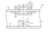
図3に示すように、第2実施形態では、生体デバイス110が第1実施形態の第2スペーサ50を有していない点と、絶縁シート160の配置と、が第1実施形態と比べて主に異なっている。絶縁シート160は、電子ユニット30の第1方向D1を向く面に取り付けられている。As shown in FIG. 3, the second embodiment is different from the first embodiment mainly in that the
(2-1)上記第2実施形態によれば、絶縁シート160は、電子ユニット30に取り付けられている。そのため、第1実施形態における第2スペーサ50を省くことができる。また、第1実施形態と比べて、絶縁シート160及び気液分離体40をいずれもケース20の内面に取り付ける場合と比べて、絶縁シート160と気液分離体40とを離して配置させやすい。これにより、絶縁シート160が気液分離体40をすべて覆ってしまうことで、絶縁シート160によって、連通孔21を介した気体の流通を遮断することを防ぎやすい。また、ケース20と比べて、電子ユニット30は変形しにくいため、絶縁シート160の位置が使用によりずれることを抑制できる。(2-1) According to the second embodiment, the insulating sheet 160 is attached to the
(第3実施形態)
以下、生体デバイスの第3実施形態について、図面を参照して説明する。なお、以下では、第1実施形態における生体デバイス10と比べて異なる点を中心に説明し、同一の点については詳細を簡略又は省略する。 Third Embodiment
Hereinafter, the third embodiment of the biodevice will be described with reference to the drawings. Note that the following description will focus on the differences from the
図4に示すように、第3実施形態では、生体デバイス210の第2スペーサ250及び絶縁シート260の位置が、第1実施形態と比べて異なっている。第2スペーサ250は、ケース20の外面に、図示しない接着剤を介して取り付けられている。また、2つの第2スペーサ250の間の隙間は、第1実施形態と比べて狭くなっている。As shown in FIG. 4, in the third embodiment, the positions of the
絶縁シート260は、第2スペーサ250の第1方向D1を向く面に、図示しない接着剤を介して取り付けられている。第2方向D2を向いて生体デバイス10を視たとき、絶縁シート260の面積は、第1実施形態と比べて小さくなっている。具体的には、絶縁シート260の一辺の寸法は、気液分離シート42の直径の寸法と等しくなっている。The insulating
このようにして、第2スペーサ250及び絶縁シート260がケース20の外部空間に配置されている。そのため、第1方向D1に向かって、電子ユニット30、気液分離体40、連通孔21、絶縁シート260、の順に位置している。In this way, the
(3-1)上記第3実施形態によれば、絶縁シート260を、第2スペーサ250を介して、ケース20の外面に取り付けることができる。そのため、第1実施形態と比べて、絶縁シート260をケース20に取り付ける際に、気液分離体40の位置を考慮しなくて済む。よって、絶縁シート260をケース20に取り付ける作業が容易になる。(3-1) According to the third embodiment, the insulating
(第4実施形態)
以下、生体デバイスの第4実施形態について、図面を参照して説明する。なお、以下では、第3実施形態における生体デバイス210と比べて異なる点を中心に説明し、同一の点については詳細を簡略又は省略する。 Fourth Embodiment
Hereinafter, the fourth embodiment of the biodevice will be described with reference to the drawings. Note that the following description will focus on the differences from the
図5に示すように、第4実施形態では、生体デバイス310の第2スペーサ350及び絶縁シート360の位置と、気液分離体340の位置とが、第3実施形態と比べて入れ替わっている。As shown in FIG. 5, in the fourth embodiment, the positions of the
具体的には、気液分離体340の第1スペーサ341は、ケース20の外面に、図示しない接着剤を介して取り付けられている。また、気液分離シート342は、第1スペーサ341の第1方向D1を向く面に、図示しない接着剤を介して取り付けられている。Specifically, the
各第2スペーサ350は、ケース20の内面に、図示しない接着剤を介して取り付けられている。また、絶縁シート360は、各第2スペーサ350の第2方向D2を向く面に、図示しない接着剤を介して取り付けられている。Each
このようにして、気液分離体340がケース20の外部空間に配置されている。一方で、第2スペーサ350及び絶縁シート360は、ケース20の内部空間Sに配置されている。そのため、第1方向D1に向かって、電子ユニット30、絶縁シート360、連通孔21、気液分離体340、の順に位置している。In this way, the gas-
(4-1)上記第4実施形態によれば、気液分離体340を、ケース20の外面に取り付けることができる。そのため、第1実施形態と比べて、気液分離体340をケース20に取り付ける際に、絶縁シート360の位置を考慮しなくて済む。よって、絶縁シート360をケース20に取り付ける作業が容易になる。(4-1) According to the fourth embodiment, the gas-
(第5実施形態)
以下、生体デバイスの第5実施形態について、図面を参照して説明する。なお、以下では、第1実施形態における生体デバイス10と比べて異なる点を中心に説明し、同一の点については詳細を簡略又は省略する。 Fifth Embodiment
Hereinafter, the fifth embodiment of the biodevice will be described with reference to the drawings. Note that the following description will focus on the differences from the
図6に示すように、第5実施形態では、生体デバイス410の気液分離体440の位置が、第1実施形態と比べて異なっている。具体的には、気液分離体440は、連通孔21の内部に収容されている。特に、本実施形態では、気液分離体440は、連通孔21の内部をすべて埋めている。これにより、気液分離体440は、連通孔21を塞いでいる。さらに、気液分離体440は、連通孔21の内部のみに存在している。つまり、気液分離体440は、連通孔21の外部にはみ出していない。よって、第5実施形態では、ケース20は、連通孔21を有していないといえる。そして、ケース20の壁の一部は、気液分離体440によって構成されている。なお、第5実施形態では、気液分離体440を介して、ケース20の壁の厚み方向において、ケース20の内部空間Sとケース20の外部区間とを、気体が通過可能になる。よって、ケース20の壁のうち気液分離体440が構成する箇所の壁の厚み方向と、仮想軸AXとが一致する。As shown in FIG. 6, in the fifth embodiment, the position of the gas-
このようにして、仮想軸AXに沿う方向において、連通孔21と気液分離体440とは、同じ箇所に位置している。そして、第1方向D1に向かって、電子ユニット30、絶縁シート60、連通孔21、の順に位置している。In this way, the
なお、生体デバイス410の第2スペーサ450の仮想軸AXに沿う方向の寸法は、第1実施形態と比べて、小さくなっている。
(5-1)上記第5実施形態によれば、気液分離体440を配置するために、連通孔21の内部の空間を活用できる。そのため、気液分離体440を設けるために、過度に大きな内部空間Sは必要なくなる。その結果、生体デバイス410の大型化が抑制されやすくなる。 The dimension of the
(5-1) According to the fifth embodiment, the space inside the
(5-2)上記第5実施形態によれば、絶縁シート60は、内部空間Sに配置される。そのため、生体デバイス410を身体に取り付けて使用する際に、絶縁シート60は、ケース20によって保護される。(5-2) According to the fifth embodiment, the insulating
(その他の実施形態)
上記各実施形態は、以下のように変更して実施することができる。上記各実施形態及び以下の変更例は、技術的に矛盾しない範囲で組み合わせて実施することができる。 Other Embodiments
The above-described embodiments may be modified as follows: The above-described embodiments and the following modifications may be combined and implemented within the scope of technical compatibility.
・生体デバイスは、身体に装着して使用されるデバイスであれば、生体センサに限られない。つまり、電子ユニット30がセンサを有していなくてもよい。
なお、生体デバイスが生体センサである場合、例えば、生体デバイスを身体に装着した状態で、生体デバイスを取り付けた箇所の近傍で、電気メスや除細動器などの放電する機器を使用するため、ケース20の外部から電流が入り込みやすい。そのため、絶縁シートを設けることによる効果を得る必要性がより高い。 The biodevice is not limited to a biosensor as long as it is a device worn on the body. In other words, the
In addition, when the biodevice is a biosensor, for example, when the biodevice is attached to the body, a discharging device such as an electric scalpel or a defibrillator is used near the location where the biodevice is attached, so that current is likely to enter from outside the
・ケース20は、フィルム状であってもよい。つまり、ケース20は、自身で形状を保つことができない程度の剛性しか有していなくてもよい。この場合、ケース20を身体に装着した状態での仮想軸AXを基準とすればよい。-
・気液分離体の材質は、ポリテトラフルオロエチレンに限られない。気液分離体の材質は、気体を通し、且つ液体の水を通さない材質であればよい。また、気液分離体の耐水度は、30kPa以上であればよい。- The material of the gas-liquid separator is not limited to polytetrafluoroethylene. The material of the gas-liquid separator may be any material that allows gas to pass through but does not allow liquid water to pass through. In addition, the water resistance of the gas-liquid separator may be 30 kPa or more.
・気液分離体の形状は、連通孔21を塞いでいれば適宜変更してもよい。例えば、第1実施形態において、気液分離体40は、ブロック状となっていてもよい。なお、第5実施形態のように、気液分離体440が連通孔21を塞いだ結果、ケース20に連通孔21がなくなっていてもよい。- The shape of the gas-liquid separator may be changed as appropriate as long as it blocks the
・第1実施形態~第4実施形態において、気液分離体は、第5実施形態のように、第1スペーサを省いてもよい。例えば、第1実施形態において、気液分離シート42は、ケース20の内面に第1スペーサ41を介さずに取り付けられてもよい。- In the first to fourth embodiments, the gas-liquid separator may omit the first spacer, as in the fifth embodiment. For example, in the first embodiment, the gas-
・第2スペーサの形状は、上記各実施形態の例に限られない。例えば、第1実施形態において、第2方向D2を向いて生体デバイス10を透視したときに、第2スペーサ50は、C字状であってもよいし、渦巻状であってもよい。これらの場合、第2方向D2を向いて生体デバイス10を透視したときに、第2スペーサ50は、連通孔21を部分的に取り囲んでいる。The shape of the second spacer is not limited to the examples in the above embodiments. For example, in the first embodiment, when the
・第1実施形態、第3実施形態~第5実施形態において、第2方向D2を向いて生体デバイスを透視したときに、第2スペーサは、連通孔21の全体を取り囲んでいてもよい。この場合、例えば、第1実施形態において、絶縁シート60と第2スペーサ50との間に一部隙間があったり、第2スペーサ50の材質が気体を通す材質であったりすればよい。このようにして、第2方向D2を向いて生体デバイス10を透視したときに、第2スペーサ50の内側の空間と第2スペーサ50の外側の空間との気体の流通を遮断しなければよい。In the first and third to fifth embodiments, when the
・第2スペーサの材質は、絶縁体でなくてもよい。
・第3実施形態において、生体デバイス210は、第2スペーサ250を省いてもよい。この点、第4実施形態及び第5実施形態においても同様である。 The material of the second spacer does not have to be an insulating material.
In the third embodiment, the
・第2方向D2を向いて生体デバイスを透視したときに、絶縁シートの面積は、上記各実施形態の例に限られない。例えば、第1実施形態において、第2方向D2を向いて生体デバイス10を透視したときに、絶縁シート60の面積は、連通孔21の面積と等しくてもよい。また例えば、第1実施形態において、第2方向D2を向いて生体デバイス10を透視したときに、絶縁シート60の面積は、気液分離体40の面積以下であってもよい。- When the biodevice is viewed in the second direction D2, the area of the insulating sheet is not limited to the examples of the above embodiments. For example, in the first embodiment, when the
・各実施形態において、第1方向D1に向かう、電子ユニット30、絶縁シート、気液分離体、連通孔21の順が変わるように、各配置を変更してもよい。第1方向D1を向いて平面視したときに、気液分離体、電子ユニット30、及び絶縁シートが、連通孔21と重なっていればよい。これにより、例えば、第1実施形態において、ケース20の外部空間に、絶縁シート60及び気液分離体40が位置していてもよい。- In each embodiment, the arrangement of the
上記実施形態及び変更例から把握できる技術的思想について記載する。
<1>
連通孔を有し、身体に装着可能なケースと、
前記ケースに内蔵される電子ユニットと、
前記ケースに取り付けられる気液分離体と、
前記ケース又は前記電子ユニットに取り付けられる絶縁シートと、
を備え、
前記連通孔は第1方向に連通して前記ケースの内部空間と外部空間とをつなぎ、
前記第1方向において、前記気液分離体と前記絶縁シートとは離れて配置され、
前記第1方向を向いて平面視したときに、前記気液分離体、前記電子ユニット、及び前記絶縁シートは、前記連通孔と重なっている
生体デバイス。 The technical ideas that can be understood from the above-described embodiment and modified examples will be described.
<1>
A case having a communication hole and capable of being worn on the body;
an electronic unit housed in the case;
A gas-liquid separator attached to the case;
an insulating sheet attached to the case or the electronic unit;
Equipped with
the communication hole communicates in a first direction to connect an internal space and an external space of the case,
The gas-liquid separator and the insulating sheet are disposed apart from each other in the first direction,
the gas-liquid separator, the electronic unit, and the insulating sheet overlap with the communication hole when viewed in a plan view facing the first direction.
<2>
前記ケースと前記絶縁シートとの間に介在するスペーサをさらに備え、
前記スペーサは、前記第1方向を向いて平面視したときに、前記連通孔を挟むように配置されている
<1>に記載の生体デバイス。 <2>
A spacer is further provided between the case and the insulating sheet.
The biodevice according to <1>, wherein the spacers are arranged to sandwich the communication hole when viewed in a plan view facing the first direction.
<3>
前記第1方向を向いて平面視したときに、
前記絶縁シートの面積は、前記連通孔の面積よりも大きくなっている
<1>又は<2>に記載の生体デバイス。 <3>
When viewed in a plan view facing the first direction,
The biodevice according to <1> or <2>, wherein an area of the insulating sheet is larger than an area of the communication hole.
<4>
前記第1方向を向いて平面視したときに、
前記絶縁シートの面積は、前記気液分離体の面積よりも大きくなっている
<1>~<3>のいずれか1つに記載の生体デバイス。 <4>
When viewed in a plan view facing the first direction,
The biodevice according to any one of <1> to <3>, wherein the area of the insulating sheet is larger than the area of the gas-liquid separator.
<5>
前記第1方向を前記ケースの内部空間から外部空間に向かう方向としたとき、
前記第1方向に向かって、前記電子ユニット、前記絶縁シート、前記気液分離体、前記連通孔、の順に位置している
<1>~<4>のいずれか1つに記載の生体デバイス。 <5>
When the first direction is a direction from the internal space of the case toward the external space,
The biodevice according to any one of <1> to <4>, wherein the electronic unit, the insulating sheet, the gas-liquid separator, and the communication hole are positioned in this order in the first direction.
<6>
前記第1方向を前記ケースの内部空間から外部空間に向かう方向としたとき、
前記第1方向に向かって、前記電子ユニット、前記絶縁シート、前記貫通孔、前記気液分離体、の順に位置している
<1>~<4>のいずれか1つに記載の生体デバイス。 <6>
When the first direction is a direction from the internal space of the case toward the external space,
The biodevice according to any one of <1> to <4>, wherein the electronic unit, the insulating sheet, the through hole, and the gas-liquid separator are positioned in this order in the first direction.
<7>
前記貫通孔の開口する方向のうち、前記内部空間から前記ケースの外部空間に向かう方向を第1方向としたとき、
前記第1方向に向かって、前記電子ユニット、前記絶縁シート、前記貫通孔、前記気液分離体、の順に位置している
<1>~<4>のいずれか1つに記載の生体デバイス。 <7>
When a direction from the internal space toward the external space of the case is defined as a first direction among directions in which the through hole opens,
The biodevice according to any one of <1> to <4>, wherein the electronic unit, the insulating sheet, the through hole, and the gas-liquid separator are positioned in this order in the first direction.
<8>
身体に装着可能なケースと、
前記ケースの壁の一部を構成し、当該壁の厚み方向である第1方向において前記ケースの内部空間と外部空間とを気体が通過可能に配置される気液分離体と、
前記ケースに内蔵される電子ユニットと、
前記ケース又は前記電子ユニットに取り付けられる絶縁シートと、
を備え、
前記第1方向において、前記気液分離体と前記絶縁シートとは離れて配置され、
前記第1方向を向いて平面視したときに、前記気液分離体、前記電子ユニット、及び前記絶縁シートは重なっている
生体デバイス。 <8>
A case that can be worn on the body,
a gas-liquid separator that constitutes a part of a wall of the case and is arranged to allow gas to pass between an internal space and an external space of the case in a first direction that is a thickness direction of the wall;
an electronic unit housed in the case;
an insulating sheet attached to the case or the electronic unit;
Equipped with
The gas-liquid separator and the insulating sheet are disposed apart from each other in the first direction,
The biodevice, when viewed in a plan view facing the first direction, has the gas-liquid separator, the electronic unit, and the insulating sheet overlapping each other.
<9>
前記第1方向を前記ケースの内部空間から外部空間に向かう方向としたとき、
前記第1方向に向かって、前記電子ユニット、前記絶縁シート、前記気液分離体、の順に位置している
<8>に記載の生体デバイス。 <9>
When the first direction is a direction from the internal space of the case toward the external space,
The biodevice according to <8>, wherein the electronic unit, the insulating sheet, and the gas-liquid separator are positioned in this order in the first direction.
10,110,210,310,410…生体デバイス
20…ケース
21…連通孔
30…電子ユニット
40,340,440…気液分離体
41,341…第1スペーサ
42,342…気液分離シート
50,250,350,450…第2スペーサ
60,160,260,360…絶縁シート
AX…仮想軸
S…内部空間
Claims (6)
Translated fromJapanese前記ケースに内蔵される電子ユニットと、
前記ケースに取り付けられる気液分離体と、
前記ケース又は前記電子ユニットに取り付けられる絶縁シートと、
前記ケースと前記絶縁シートとの間に介在するスペーサと、
を備え、
前記連通孔は第1方向に連通して前記ケースの内部空間と外部空間とをつなぎ、
前記第1方向において、前記気液分離体と前記絶縁シートとは離れて配置され、
前記第1方向を向いて平面視したときに、前記気液分離体、前記電子ユニット、及び前記絶縁シートは、前記連通孔と重なっており、
前記スペーサは、前記第1方向を向いて平面視したときに、前記連通孔を挟むように配置されている
生体デバイス。 A case having a communication hole and capable of being worn on the body;
an electronic unit housed in the case;
A gas-liquid separator attached to the case;
an insulating sheet attached to the case or the electronic unit;
a spacer interposed between the case and the insulating sheet;
Equipped with
the communication hole communicates in a first direction to connect an internal space and an external space of the case,
The gas-liquid separator and the insulating sheet are disposed apart from each other in the first direction,
When viewed in a plan view in the first direction, the gas-liquid separator, the electronic unit, and the insulating sheet overlap with the communication hole,
The spacer is disposed so as to sandwich the communication hole when viewed in a plan view facing the first direction.
Biometric device.
前記絶縁シートの面積は、前記連通孔の面積よりも大きくなっている
請求項1に記載の生体デバイス。 When viewed in a plan view facing the first direction,
The biodevice according to claim 1 , wherein the area of the insulating sheet is larger than the area of the communication hole.
前記絶縁シートの面積は、前記気液分離体の面積よりも大きくなっている
請求項1に記載の生体デバイス。 When viewed in a plan view facing the first direction,
The biodevice according to claim 1 , wherein the area of the insulating sheet is larger than the area of the gas-liquid separator.
前記第1方向に向かって、前記電子ユニット、前記絶縁シート、前記気液分離体、前記連通孔、の順に位置している
請求項1~請求項3のいずれか1項に記載の生体デバイス。 When the first direction is a direction from the internal space of the case toward the external space,
The electronic unit, the insulating sheet, the gas-liquid separator, and the communication hole are positioned in this order in the first direction.
The biodevice according to any one ofclaims 1 to 3 .
前記ケースに内蔵される電子ユニットと、
前記ケースに取り付けられる気液分離体と、
前記ケース又は前記電子ユニットに取り付けられる絶縁シートと、
を備え、
前記連通孔は第1方向に連通して前記ケースの内部空間と外部空間とをつなぎ、
前記第1方向において、前記気液分離体と前記絶縁シートとは離れて配置され、
前記第1方向を向いて平面視したときに、前記気液分離体、前記電子ユニット、及び前記絶縁シートは、前記連通孔と重なっており、
前記第1方向を前記ケースの内部空間から外部空間に向かう方向としたとき、
前記第1方向に向かって、前記電子ユニット、前記気液分離体、前記連通孔、前記絶縁シート、の順に位置している
生体デバイス。 A case having a communication hole and capable of being worn on the body;
an electronic unit housed in the case;
A gas-liquid separator attached to the case;
an insulating sheet attached to the case or the electronic unit;
Equipped with
the communication hole communicates in a first direction to connect an internal space and an external space of the case,
The gas-liquid separator and the insulating sheet are disposed apart from each other in the first direction,
When viewed in a plan view in the first direction, the gas-liquid separator, the electronic unit, and the insulating sheet overlap with the communication hole,
When the first direction is a direction from the internal space of the case toward the external space,
The electronic unit, the gas-liquid separator, the communication hole, and the insulating sheet are positioned in this order in the first direction.
Biometric device.
前記ケースに内蔵される電子ユニットと、
前記ケースに取り付けられる気液分離体と、
前記ケース又は前記電子ユニットに取り付けられる絶縁シートと、
を備え、
前記連通孔は第1方向に連通して前記ケースの内部空間と外部空間とをつなぎ、
前記第1方向において、前記気液分離体と前記絶縁シートとは離れて配置され、
前記第1方向を向いて平面視したときに、前記気液分離体、前記電子ユニット、及び前記絶縁シートは、前記連通孔と重なっており、
前記第1方向を前記ケースの内部空間から外部空間に向かう方向としたとき、
前記第1方向に向かって、前記電子ユニット、前記絶縁シート、前記連通孔、前記気液分離体、の順に位置している
生体デバイス。 A case having a communication hole and capable of being worn on the body;
an electronic unit housed in the case;
A gas-liquid separator attached to the case;
an insulating sheet attached to the case or the electronic unit;
Equipped with
the communication hole communicates in a first direction to connect an internal space and an external space of the case,
The gas-liquid separator and the insulating sheet are disposed apart from each other in the first direction,
When viewed in a plan view in the first direction, the gas-liquid separator, the electronic unit, and the insulating sheet overlap with the communication hole,
When the first direction is a direction from the internal space of the case toward the external space,
The electronic unit, the insulating sheet, the communication hole, and the gas-liquid separator are positioned in this order in the first direction.
Biometric device.
Priority Applications (2)
| Application Number | Priority Date | Filing Date | Title |
|---|---|---|---|
| JP2022099118AJP7635755B2 (en) | 2022-06-20 | 2022-06-20 | Biological Devices |
| US18/328,529US12309945B2 (en) | 2022-06-20 | 2023-06-02 | Biological device |
Applications Claiming Priority (1)
| Application Number | Priority Date | Filing Date | Title |
|---|---|---|---|
| JP2022099118AJP7635755B2 (en) | 2022-06-20 | 2022-06-20 | Biological Devices |
Publications (2)
| Publication Number | Publication Date |
|---|---|
| JP2024000369A JP2024000369A (en) | 2024-01-05 |
| JP7635755B2true JP7635755B2 (en) | 2025-02-26 |
Family
ID=89168890
Family Applications (1)
| Application Number | Title | Priority Date | Filing Date |
|---|---|---|---|
| JP2022099118AActiveJP7635755B2 (en) | 2022-06-20 | 2022-06-20 | Biological Devices |
Country Status (2)
| Country | Link |
|---|---|
| US (1) | US12309945B2 (en) |
| JP (1) | JP7635755B2 (en) |
Citations (3)
| Publication number | Priority date | Publication date | Assignee | Title |
|---|---|---|---|---|
| US20170340279A1 (en) | 2014-12-22 | 2017-11-30 | Tsinghua University | Flexible extensile electronic device based on biocompatible film and preparation method |
| WO2019065029A1 (en) | 2017-09-29 | 2019-04-04 | マクセルホールディングス株式会社 | Waterproof device |
| JP2019063230A (en) | 2017-09-29 | 2019-04-25 | マクセルホールディングス株式会社 | device |
Family Cites Families (8)
| Publication number | Priority date | Publication date | Assignee | Title |
|---|---|---|---|---|
| AT411331B (en)* | 2002-04-09 | 2003-12-29 | Brain Flash Patententwicklungs | FILTER MODULE |
| US9135402B2 (en)* | 2007-12-17 | 2015-09-15 | Dexcom, Inc. | Systems and methods for processing sensor data |
| US8369919B2 (en)* | 2003-08-01 | 2013-02-05 | Dexcom, Inc. | Systems and methods for processing sensor data |
| CN103081209B (en)* | 2011-04-11 | 2016-08-10 | 松下知识产权经营株式会社 | Thin battery and cell apparatus |
| US10549106B2 (en)* | 2016-08-11 | 2020-02-04 | Cardiac Pacemakers, Inc. | External audit of implantable medical device |
| US20190000349A1 (en)* | 2017-06-28 | 2019-01-03 | Incyphae Inc. | Diagnosis tailoring of health and disease |
| US11547343B2 (en)* | 2019-04-12 | 2023-01-10 | Cardiac Pacemakers, Inc. | PVC adjusted AF detection |
| KR102819930B1 (en)* | 2020-09-29 | 2025-06-11 | 삼성전자주식회사 | Stretchable device system and electronic device |
- 2022
- 2022-06-20JPJP2022099118Apatent/JP7635755B2/enactiveActive
- 2023
- 2023-06-02USUS18/328,529patent/US12309945B2/enactiveActive
Patent Citations (3)
| Publication number | Priority date | Publication date | Assignee | Title |
|---|---|---|---|---|
| US20170340279A1 (en) | 2014-12-22 | 2017-11-30 | Tsinghua University | Flexible extensile electronic device based on biocompatible film and preparation method |
| WO2019065029A1 (en) | 2017-09-29 | 2019-04-04 | マクセルホールディングス株式会社 | Waterproof device |
| JP2019063230A (en) | 2017-09-29 | 2019-04-25 | マクセルホールディングス株式会社 | device |
Also Published As
| Publication number | Publication date |
|---|---|
| US20230413460A1 (en) | 2023-12-21 |
| JP2024000369A (en) | 2024-01-05 |
| US12309945B2 (en) | 2025-05-20 |
Similar Documents
| Publication | Publication Date | Title |
|---|---|---|
| US9521226B2 (en) | Molded shock resistant case for an electronic device | |
| CN100539248C (en) | battery module | |
| JP6625377B2 (en) | Battery system with improved swelling CID operation reliability | |
| JP7230226B2 (en) | Insulating plate for secondary battery and secondary battery including the insulating plate | |
| US9121517B2 (en) | Rupture disk and gas insulated switchgear having the same | |
| JP6423552B2 (en) | Electronic control unit | |
| EP3570344B1 (en) | Secondary battery and top cover assembly thereof | |
| WO2005106988A1 (en) | Laminate type secondary battery and battery pack thereof | |
| CN104134770A (en) | Pouch type secondary battery with safety vent | |
| CN105977411B (en) | Secondary cell top cap and secondary cell | |
| JP6489402B2 (en) | Power storage device | |
| JP7635755B2 (en) | Biological Devices | |
| CN105895836A (en) | Power battery top cap and power battery | |
| US20200358063A1 (en) | Battery pack | |
| CN110073515A (en) | The battery system of water proof structure | |
| EP3748713A1 (en) | Battery pack | |
| EP3748716A1 (en) | Battery pack | |
| WO2013005432A1 (en) | External operation detection structure body | |
| JP7045587B2 (en) | Secondary battery | |
| CN208690313U (en) | Power battery top cover | |
| KR20130116174A (en) | Battery pack | |
| JP4439321B2 (en) | Electric therapy device | |
| WO2017208410A1 (en) | Urine-receiving pad | |
| CN115022753A (en) | Speaker grill assembly and portable wireless communication device | |
| KR20250054374A (en) | Battery assembly |
Legal Events
| Date | Code | Title | Description |
|---|---|---|---|
| A621 | Written request for application examination | Free format text:JAPANESE INTERMEDIATE CODE: A621 Effective date:20240109 | |
| A131 | Notification of reasons for refusal | Free format text:JAPANESE INTERMEDIATE CODE: A131 Effective date:20241112 | |
| A521 | Request for written amendment filed | Free format text:JAPANESE INTERMEDIATE CODE: A523 Effective date:20250106 | |
| TRDD | Decision of grant or rejection written | ||
| A01 | Written decision to grant a patent or to grant a registration (utility model) | Free format text:JAPANESE INTERMEDIATE CODE: A01 Effective date:20250114 | |
| A61 | First payment of annual fees (during grant procedure) | Free format text:JAPANESE INTERMEDIATE CODE: A61 Effective date:20250127 | |
| R150 | Certificate of patent or registration of utility model | Ref document number:7635755 Country of ref document:JP Free format text:JAPANESE INTERMEDIATE CODE: R150 |