JP7635069B2 - LIQUID CONTAINER AND LIQUID EJECTION APPARATUS - Google Patents
LIQUID CONTAINER AND LIQUID EJECTION APPARATUSDownload PDFInfo
- Publication number
- JP7635069B2 JP7635069B2JP2021083081AJP2021083081AJP7635069B2JP 7635069 B2JP7635069 B2JP 7635069B2JP 2021083081 AJP2021083081 AJP 2021083081AJP 2021083081 AJP2021083081 AJP 2021083081AJP 7635069 B2JP7635069 B2JP 7635069B2
- Authority
- JP
- Japan
- Prior art keywords
- liquid
- liquid storage
- storage chamber
- partition member
- gravity
- Prior art date
- Legal status (The legal status is an assumption and is not a legal conclusion. Google has not performed a legal analysis and makes no representation as to the accuracy of the status listed.)
- Active
Links
Images


Classifications
- B—PERFORMING OPERATIONS; TRANSPORTING
- B41—PRINTING; LINING MACHINES; TYPEWRITERS; STAMPS
- B41J—TYPEWRITERS; SELECTIVE PRINTING MECHANISMS, i.e. MECHANISMS PRINTING OTHERWISE THAN FROM A FORME; CORRECTION OF TYPOGRAPHICAL ERRORS
- B41J2/00—Typewriters or selective printing mechanisms characterised by the printing or marking process for which they are designed
- B41J2/005—Typewriters or selective printing mechanisms characterised by the printing or marking process for which they are designed characterised by bringing liquid or particles selectively into contact with a printing material
- B41J2/01—Ink jet
- B41J2/17—Ink jet characterised by ink handling
- B41J2/175—Ink supply systems ; Circuit parts therefor
- B41J2/17503—Ink cartridges
- B41J2/17506—Refilling of the cartridge
- B41J2/17509—Whilst mounted in the printer
- B—PERFORMING OPERATIONS; TRANSPORTING
- B41—PRINTING; LINING MACHINES; TYPEWRITERS; STAMPS
- B41J—TYPEWRITERS; SELECTIVE PRINTING MECHANISMS, i.e. MECHANISMS PRINTING OTHERWISE THAN FROM A FORME; CORRECTION OF TYPOGRAPHICAL ERRORS
- B41J2/00—Typewriters or selective printing mechanisms characterised by the printing or marking process for which they are designed
- B41J2/005—Typewriters or selective printing mechanisms characterised by the printing or marking process for which they are designed characterised by bringing liquid or particles selectively into contact with a printing material
- B41J2/01—Ink jet
- B41J2/17—Ink jet characterised by ink handling
- B41J2/175—Ink supply systems ; Circuit parts therefor
- B41J2/17503—Ink cartridges
- B41J2/1752—Mounting within the printer
- B41J2/17523—Ink connection
- B—PERFORMING OPERATIONS; TRANSPORTING
- B41—PRINTING; LINING MACHINES; TYPEWRITERS; STAMPS
- B41J—TYPEWRITERS; SELECTIVE PRINTING MECHANISMS, i.e. MECHANISMS PRINTING OTHERWISE THAN FROM A FORME; CORRECTION OF TYPOGRAPHICAL ERRORS
- B41J2/00—Typewriters or selective printing mechanisms characterised by the printing or marking process for which they are designed
- B41J2/005—Typewriters or selective printing mechanisms characterised by the printing or marking process for which they are designed characterised by bringing liquid or particles selectively into contact with a printing material
- B41J2/01—Ink jet
- B41J2/17—Ink jet characterised by ink handling
- B41J2/175—Ink supply systems ; Circuit parts therefor
- B41J2/17503—Ink cartridges
- B41J2/17513—Inner structure
- B—PERFORMING OPERATIONS; TRANSPORTING
- B41—PRINTING; LINING MACHINES; TYPEWRITERS; STAMPS
- B41J—TYPEWRITERS; SELECTIVE PRINTING MECHANISMS, i.e. MECHANISMS PRINTING OTHERWISE THAN FROM A FORME; CORRECTION OF TYPOGRAPHICAL ERRORS
- B41J2/00—Typewriters or selective printing mechanisms characterised by the printing or marking process for which they are designed
- B41J2/005—Typewriters or selective printing mechanisms characterised by the printing or marking process for which they are designed characterised by bringing liquid or particles selectively into contact with a printing material
- B41J2/01—Ink jet
- B41J2/17—Ink jet characterised by ink handling
- B41J2/175—Ink supply systems ; Circuit parts therefor
- B41J2/17503—Ink cartridges
- B41J2/17559—Cartridge manufacturing
- B—PERFORMING OPERATIONS; TRANSPORTING
- B41—PRINTING; LINING MACHINES; TYPEWRITERS; STAMPS
- B41J—TYPEWRITERS; SELECTIVE PRINTING MECHANISMS, i.e. MECHANISMS PRINTING OTHERWISE THAN FROM A FORME; CORRECTION OF TYPOGRAPHICAL ERRORS
- B41J2/00—Typewriters or selective printing mechanisms characterised by the printing or marking process for which they are designed
- B41J2/005—Typewriters or selective printing mechanisms characterised by the printing or marking process for which they are designed characterised by bringing liquid or particles selectively into contact with a printing material
- B41J2/01—Ink jet
- B41J2/17—Ink jet characterised by ink handling
- B41J2/175—Ink supply systems ; Circuit parts therefor
- B41J2/17503—Ink cartridges
- B41J2/17513—Inner structure
- B41J2002/17516—Inner structure comprising a collapsible ink holder, e.g. a flexible bag
Landscapes
- Engineering & Computer Science (AREA)
- Manufacturing & Machinery (AREA)
- Ink Jet (AREA)
Description
Translated fromJapanese本開示は、液体を吐出する液体吐出装置に使用される液体収容容器に関する。This disclosure relates to a liquid storage container used in a liquid ejection device that ejects liquid.
液体吐出装置に液体を供給するための液体収容容器が知られている。沈降成分を含む液体が液体収容容器に収容される場合、沈降成分が沈降して液体収容容器内の液体の濃度が不均一になる虞がある。Liquid storage containers are known for supplying liquid to liquid ejection devices. When liquid containing sedimentation components is stored in the liquid storage container, there is a risk that the sedimentation components will settle, causing the concentration of the liquid in the liquid storage container to become non-uniform.
特許文献1には、液体収容部における重力方向側の下端部に第1液体吸込み部を配置し、反重力方向側に第2液体吸込み部を配置することで、沈降成分の濃度が均一な液体を液体噴射部に供給する技術が記載されている。
しかしながら、長期保管または長期間の未使用状態により、液体収容容器が長時間同一姿勢で静置されると、液体収容容器の下層部において液体の沈降が更に進行する虞がある。更に濃度が濃くなった液体は、流動性が低下してしまい、均一な濃度での安定的な液体供給が困難となる虞がある。However, if a liquid container is left stationary in the same position for an extended period of time due to long-term storage or unused status, there is a risk that the settling of the liquid will progress further in the lower part of the liquid container. The liquid that has become even more concentrated will have reduced fluidity, and there is a risk that it will become difficult to stably supply liquid at a uniform concentration.
本開示は、均一な濃度での安定的な液体供給を行う液体収容容器を提供することを目的とする。The present disclosure aims to provide a liquid storage container that provides a stable supply of liquid at a uniform concentration.
本開示の一態様に係る液体収容容器は、沈降成分を有する液体を液体吐出装置に供給可能な液体収容容器であって、液体を収容する液体収容室と、重力方向に交差する方向において前記液体収容室を区分けする仕切り部材と、前記液体収容室の液体を導入して前記液体吐出装置に供給するための連通流路ユニットと、を備え、前記液体収容室は、一つの前記仕切り部材によって、前記仕切り部材よりも重力方向上方の第1液体収容室と、前記仕切り部材よりも重力方向下方の第2液体収容室と、に区分けされ、前記第1液体収容室および前記第2液体収容室にそれぞれ、前記連通流路ユニットが設けられ、前記第1液体収容室に設けられた前記連通流路ユニットは、前記重力方向において中央部よりも下方の位置に、液体を導入する液体導入部を備え、前記第2液体収容室に設けられた前記連通流路ユニットは、前記重力方向において中央部よりも上方の位置に、液体を導入する液体導入部を備えていることを特徴とする。 A liquid storage container according to one aspect of the present disclosure is a liquid storage container capable of supplying a liquid having a sedimentation component to a liquid ejection device,and comprises a liquid storage chamber for storing a liquid, a partition member thatdivides the liquid storage chamber ina direction intersecting the direction of gravity, and a communicating flow path unit for introducing liquid from the liquid storage chamber andsupplying it to the liquid ejection device, wherein the liquid storage chamber is divided by the single partition member into a first liquid storage chamber above the partition member in the direction of gravity and a second liquid storage chamber below the partition member in the direction of gravity, the first liquid storage chamber and the second liquid storage chamber are each provided with the communicating flow path unit, the communicating flow path unit provided in the first liquid storage chamber comprises a liquid introduction portion that introduces liquid at a position below a center in the direction of gravity, and the communicating flow path unit provided in the second liquid storage chamber comprises a liquid introduction portion that introduces liquid at a position above the center in the direction of gravity .
本開示によれば、均一な濃度での安定的な液体供給を行うことが可能となる。This disclosure makes it possible to provide a stable supply of liquid at a uniform concentration.
以下、添付図面を参照して本開示の好適な実施の形態を詳しく説明する。尚、以下の実施の形態は本開示事項を限定するものでなく、また本実施の形態で説明されている特徴の組み合わせすべてが本開示の解決手段に必須のものとは限らない。Below, preferred embodiments of the present disclosure are described in detail with reference to the attached drawings. Note that the following embodiments do not limit the subject matter of the present disclosure, and not all combinations of features described in the present embodiments are necessarily essential to the solution of the present disclosure.
<<第1実施形態>>
<液体吐出装置>
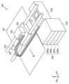
図1は、本実施形態による液体吐出装置100の概略の構成を示す斜視図である。図1に示す液体吐出装置100は、液体吐出ヘッド101の往復移動と、記録媒体である記録用シート107の所定ピッチごとの搬送とを繰り返す。液体吐出装置100は、これらの動きと同期させながら液体吐出ヘッド101から、複数色のインク(液体)を選択的に吐出させ、記録媒体である記録用シート107に着弾させることで、文字、記号、及び画像等を形成することが可能である。尚、記録媒体としては、液滴を着弾させて画像を形成できるものであれば任意のものを使用してよい。例えば、紙、布、光ディスクラベル面、プラスチックシート、OHPシート、または封筒などの種々の材質および形態のものを記録媒体として使用することができる。 First Embodiment
<Liquid ejection device>
FIG. 1 is a perspective view showing a schematic configuration of a
図1において液体吐出ヘッド101は、2本のガイドレールに摺動自在に支持され、不図示のモータ等の駆動手段によりガイドレールに沿って一直線上を往復移動されるキャリッジ102に着脱可能に搭載されている。液体吐出ヘッド101の液体吐出部から吐出された液体を受ける記録用シート107は、搬送手段である搬送ローラ103により、液体吐出ヘッド101の液体吐出面に対面し、キャリッジ102の移動方向と交差する方向に搬送される。In FIG. 1, the
液体吐出ヘッド101は、それぞれ異なる色の液体を吐出するための複数のノズル列を複数の液体吐出部として有している。液体吐出ヘッド101から吐出される液体の色に対応して、液体供給口17(図3参照)を有する複数の独立した液体収容容器200が、液体供給ユニット105に着脱可能に装着される。本実施形態では、液体収容容器200a、200b、200c、および200dがそれぞれ液体供給ユニット105に装着される。尚、以降では、液体収容容器200と称する場合、複数の液体収容容器200a~200dのうちの任意の液体収容容器を指すものとする。The
液体供給ユニット105と液体吐出ヘッド101とは、それぞれ液体の色に対応した複数の液体供給チューブ106によって接続されている。液体収容容器200を液体供給ユニット105に装着することで、液体収容容器200内に貯留された各色の液体を、液体吐出ヘッド101の各ノズル列に独立して供給することが可能となる。The
液体吐出ヘッド101の往復移動範囲内で、かつ、記録用シート107の通過範囲外の領域である非吐出領域には、回復ユニット104が、液体吐出ヘッド101の液体吐出面と対面するように配置されている。回復ユニット104は、液体吐出ヘッド101の液体吐出面をキャッピングするためのキャップ部、液体吐出口面をキャッピングした状態で強制的に液体を吸引するための吸引機構、及び液体吐出面の汚れを払拭するためのクリーニングブレード等を有する。吸引動作は、液体吐出装置100の吐出動作に先立って行われる。これにより、液体吐出装置100を長期間放置後に動作させた場合でも、回復ユニット104により回復処理が行われることで、液体吐出ヘッド101における液体吐出部内の残留気泡および吐出口近傍の増粘した液体を除去できる。これにより、液体吐出ヘッド101の吐出特性が維持される。In the non-ejection area, which is within the reciprocating movement range of the
本実施形態では、液体収容容器200が液体供給ユニット105に装着および脱着される方向をY方向とする。液体収容容器200において液体供給ユニット105に装着される側は、+Y方向である。液体収容容器200の幅方向をX方向とする。液体収容容器200の高さ方向(即ち、重力方向)をZ方向とする。重力側(下方側)を-Z方向とし、反重力側(上方側)を+Z方向とする。In this embodiment, the direction in which the
図2は、本実施形態の液体の濃度分布を示す図である。本実施形態では、液体収容容器内に収容されている液体が、沈降成分である顔料色材とこれを分散させる液媒体とを含有するインクである場合を例に挙げて説明する。液体収容容器が長期間同一姿勢で静置されると、顔料は染料に比べ分子量が大きいため色材が重力の影響を受けて沈降する。このような場合、液体収容容器内の色材濃度が不均一になる現象が起こる。尚、図2では、濃度分布を段階的に表現しているが実際の濃度分布は連続的なものである。図2に示すように沈降成分の濃度に偏りがあると、液体吐出部から均一な濃度の液体が吐出されない場合が起こり得る。また、長期保管または長期間の未使用状態により、液体収容容器が長時間同一姿勢で静置されると、液体収容容器の下層部において液体の沈降が更に進行する虞がある。濃度が濃くなった液体は、流動性が低下してしまい、均一な濃度での安定的な液体供給が困難となる虞がある。本実施形態の液体収容容器200は、このような沈降成分を有する液体を用いる場合において、均一な濃度での液体を供給可能に構成されている。Figure 2 is a diagram showing the concentration distribution of the liquid in this embodiment. In this embodiment, the liquid contained in the liquid container is an ink containing a pigment colorant, which is a sedimentation component, and a liquid medium that disperses the pigment. If the liquid container is left stationary in the same position for a long period of time, the pigment has a larger molecular weight than the dye, so the colorant will sediment under the influence of gravity. In such a case, the concentration of the colorant in the liquid container becomes uneven. Note that in Figure 2, the concentration distribution is expressed in stages, but the actual concentration distribution is continuous. If there is a bias in the concentration of the sedimentation component as shown in Figure 2, it may occur that the liquid discharge unit does not discharge a liquid of a uniform concentration. In addition, if the liquid container is left stationary in the same position for a long period of time due to long-term storage or a long-term unused state, there is a risk that the sedimentation of the liquid will further progress in the lower part of the liquid container. The liquid with a high concentration will have a reduced fluidity, which may make it difficult to stably supply the liquid at a uniform concentration. The
<液体収容容器>
図3は、本実施形態における液体収容容器200の構成を示す平面図である。図4は、液体収容容器200の断面を示す図である。図4(a)は、図3のIVa-IVa断面線における断面図である。図4(b)は、図3のIVb-IVb断面線における断面図である。以下、図3および図4を参照して説明する。 <Liquid storage container>
Fig. 3 is a plan view showing the configuration of a
本実施形態の液体収容容器200は、液体供給口17を備える供給ユニット18に連通する第1連通流路ユニット11と、同じく供給ユニット18に連通する第2連通流路ユニット14とを含む。また、液体収容容器200は、沈降成分を有する液体を収容する液体収容室を、重力方向に対して交差する方向に、第1液体収容室50と第2液体収容室51とに区分けする仕切り部材13を含む。仕切り部材13は、第1連通流路ユニット11と第2連通流路ユニット14とで、挟み込まれるように構成されている。このような構成によれば、同等のサイズの液体収容容器において仕切り部材13を設けない構成に比べて、液体を収容する室の重力方向の長さ(即ち、高さ)が、略半分になる。これにより、液体が沈降する方向の濃度差を低減することができる。第1液体収容室50は、仕切り部材13と第1可撓性フィルム10とによって形成されている。第2液体収容室51は、仕切り部材13と第2可撓性フィルム16とによって形成されている。The
仕切り部材13は、製造時に位置合わせに有利な板状の硬材でもよいし、溶着性、容積アップ、低重量、及びコストダウンに優位性のあるフィルム状の軟材であってもよい。仕切り部材13は、沈降成分の偏りを抑制するため、液体供給ユニット105(図1)に装着されている姿勢において水平方向に傾きを生じないように配されていることが好ましい。The
第1連通流路ユニット11は、第1液体収容室50に収容されている液体を導入する第1液体導入部12と、導入した液体を供給ユニット18へ導く第1流路61とを備える。第2連通流路ユニット14は、第2液体収容室51に収容されている液体を導入する第2液体導入部15と、導入した液体を供給ユニット18へ導く第2流路62とを備える。供給ユニット18は、第1流路61および第2流路62から導かれた液体が合流する合流部19を備える。合流部19で合流した液体は、液体供給口17に導出される。The first communicating
第1液体収容室50に収容されている液体および第2液体収容室51に収容されている液体は、それぞれ、図4(a)の一部に模式的に示しているように、沈降成分の濃度分布が生じ得る。即ち、重力方向上方に濃度が相対的に低い液体Lが収容されており、重力方向下方に濃度が相対的に高い液体Dが収容されている。As shown in part of FIG. 4(a), the liquid contained in the first
本実施形態では、第1連通流路ユニット11と第2連通流路ユニット14とにおいて、液体導入部が配されている位置を、ユニット内において相対的に異なる位置に配している。具体的には、第1連通流路ユニット11の第1液体導入部12および第2連通流路ユニット14の第2液体導入部15は、いずれも仕切り部材13に相対的に近い位置に設けられている。即ち、仕切り部材13よりも重力方向上方(反重力側)に配されている第1連通流路ユニット11の第1液体導入部12は、第1連通流路ユニット11の重力方向の中央部よりも下方(重力側)の位置に設けられている。仕切り部材13よりも重力方向下方に配されている第2連通流路ユニット14の第2液体導入部15は、第2連通流路ユニット14の重力方向の中央部よりも上方の位置に設けられている。このような構成によれば、第1液体導入部12は沈降成分の濃度が比較的高い液体Dを導入し、第2液体導入部15は、沈降成分の濃度が比較的低い液体Lを導入することになる。これらの液体が合流部19で合流することで、より均一な濃度の液体を供給することができる。例えば、第1液体導入部12および第2液体導入部15の位置は、いずれも仕切り部材13に対して1.0mm以上かつ3.0mm以内に設けられていることが好ましい。尚、液体吐出装置100には液体収容容器200に収容されている液体を吸引するポンプ機構が配されており、ポンプ機構による吸引によって生じた負圧により、液体収容容器200内の液体が液体吐出装置100に吸い込まれる。また、液体の吸引に応じて、第1可撓性フィルム10および第2可撓性フィルム16が各連通流路ユニットに密着するように収縮する。このため、例えば第2液体導入部15の位置が仕切り部材13側に近い位置に設けられていても、残留する液体はほとんど発生しないか、または、残留する液体が発生したとしても無視し得る程度のものとなる。In this embodiment, the positions at which the liquid introduction parts are arranged in the first communicating
また、液体収容容器200からの液体の供給が進むにつれて、液体収容容器200が収縮すると、液体導入部が可撓性フィルムにより密着されてしまうこともあり得る。この結果、液体導入部から適切に液体を導入することが出来なくなることがあり得る。このため、各連通流路ユニットでは、液体導入部の近傍に溝を設け、溝の内部に液体導入部を配することが好ましい。また、液体導入部の近傍に段差またはスリットを設けて、液体導入部が可撓性フィルムと直接接触しないように構成することが好ましい。In addition, if the
次に、本実施形態の各連通流路ユニットにおいて、液体導入部が設けられている位置(Y方向の位置)を説明する。液体導入部は、各連通流路ユニットにおいて供給ユニット18とは反対側の先端(即ち、+Y方向の端部)に設けられている。図3に示すように、液体収容容器200を、液体供給口17に対向する面に向かう方向(Y方向)において三等分する。三等分した領域を、液体供給口17に近い側から、領域P1、P2、P3とする。本実施形態では、第1連通流路ユニット11および第2連通流路ユニット14の先端位置は、中央部である領域P2に位置している。先端位置が中央部である領域P2に位置している場合、先端位置は、液体収容容器200内のどの位置からもほぼ等しい距離となる。このため、液体が液体収容容器200内の全体からほぼ均等に供給され、液体収容容器200の外周部分から容器が収縮する。このため、先端位置が領域P2に位置している場合、液体の使い切り性を向上させることができる。Next, the position (position in the Y direction) where the liquid introduction part is provided in each communicating flow path unit of this embodiment will be described. The liquid introduction part is provided at the tip of each communicating flow path unit on the opposite side to the supply unit 18 (i.e., the end in the +Y direction). As shown in FIG. 3, the
尚、上記の液体収容容器では、仕切り部材13を挟み込む第1連通流路ユニット11および第2連通流路ユニット14は、対称の形状を有する例を説明した。均一な濃度の液体を供給する場合、第1連通流路ユニット11および第2連通流路ユニット14のY方向の先端位置は液体収容容器200内において略等しい位置に設けられ、流路も同程度の長さであることが好ましい。一方で、濃度を変化させた液体を供給する場合などにおいては、各連通流路ユニットの先端位置(即ち、流路の長さ)を異ならせて設けてもよい。即ち、第1連通流路ユニット11および第2連通流路ユニット14の形状は、異なっていてもよい。また、第1液体収容室50と第2液体収容室51とに収容される液体に異なる性質の液体を収容して混合した液体を供給する場合、第1連通流路ユニット11および第2連通流路ユニット14は、非対称の形状を有してもよい。In the above liquid storage container, the first communicating
<変形例>
図5は、連通流路ユニットの他の例を示す図である。図3および図4の例では、各連通流路ユニットの先端位置は、中央部である領域P2に位置する例を説明したが、液体収容容器が萎むことで液体導入部の閉鎖が回避できる位置であればよい。例えば、図5に示すように、三等分した領域において液体供給口17に近い側の領域P1に位置してもよい。図5の液体収容容器200は、第3連通流路ユニット20および第4連通流路ユニット21を備えている例である。第3連通流路ユニット20および第4連通流路ユニット21は、先端位置が第1連通流路ユニット11および第2連通流路ユニット14よりも液体供給口17側に位置している例である。ただし、図5のような場合においても、第3連通流路ユニット20及び第4連通流路ユニット21の先端位置は、できるだけ中央部である領域P2寄りの位置が好ましい。前述したように、液体を均等に吸い込むことができるからである。尚、先端位置が領域P3に位置してもよいが、この場合、流路長が、先端が領域P1およびP2にある場合に比べて長くなる。このため、流路内での沈降が発生する虞もあるので、先端は、領域P2または領域P1に位置する方が好ましい。尚、図5の例において、第3連通流路ユニット20の第3液体導入部22および第4連通流路ユニット21の第4液体導入部23の、仕切り部材13に対する位置は、図4に示した例と同様の位置に設けられている。即ち、いずれも仕切り部材13に近い位置に設けられている。 <Modification>
FIG. 5 is a diagram showing another example of the communicating flow passage unit. In the examples of FIG. 3 and FIG. 4, the leading end position of each communicating flow passage unit is located in the region P2, which is the center, but it may be located in any position that can avoid the liquid introduction portion from being closed by the liquid container shrinking. For example, as shown in FIG. 5, the leading end position may be located in the region P1 closer to the
<製造方法>
図6は、図2から図4で示した液体収容容器200を組み立てる前の状態における各部材の例を示す分解斜視図である。液体収容容器200は、液体吐出部へ液体を供給する液体供給口17と、供給ユニット18と、を備えている。また、液体収容容器200は、第1連通流路ユニット11と、第2連通流路ユニット14と、液体収容室を区分けするための仕切り部材13と、ガスバリア性に優れた第1可撓性フィルム10および第2可撓性フィルム16と、を備えている。以下、液体収容容器200の製造工程(組立工程)を説明する。尚、図6は、代表的な構成を示しており、その他の構成が含まれていてもよい。 <Production Method>
Fig. 6 is an exploded perspective view showing an example of each member of the
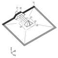
図7から図10は、液体収容容器200の製造方法を説明する図である。図7から図10につれて、製造工程が進むものとする。図7は、液体収容容器200の製造過程における斜視図である。図8は、液体収容容器200の製造過程における斜視図である。図9は、図8のIX-IX線断面における縦視断面図である。図10は、液体収容容器200の製造過程における斜視図である。FIGS. 7 to 10 are diagrams illustrating a manufacturing method for the
まず、図7の組み立て工程において、仕切り部材13を第1連通流路ユニット11および第2連通流路ユニット14で挟み込む。具体的には、仕切り部材13の重力方向上方に第1連通流路ユニット11を配し、仕切り部材13の重力方向下方に第2連通流路ユニット14を配する。そして、各連通流路ユニットで仕切り部材13を挟み込んだ状態で組み込んだ後に、供給ユニット18を第1連通流路ユニット11と第2連通流路ユニット14とに接続する。図7は、上記の工程を経た状態の図である。First, in the assembly process of FIG. 7, the
次に、第1溶着工程を行う。図8は、第1溶着工程を説明する図である。第2可撓性フィルム16上に、図7で組み合わせた仕切り部材13の外周を精度よく重ねる。そして、さらにその上に、第1可撓性フィルム10を精度よく重ね合わせる。そして、各可撓性フィルム外周をコの字に溶着してコの字溶着部70を形成し、袋状にする。図8は、上記の工程を経た状態の図である。Next, the first welding process is carried out. Figure 8 is a diagram explaining the first welding process. The outer periphery of the
次に、液体注入工程を行う。図9は、液体注入工程を説明する図である。図9は、図8のIX-IX線の縦視断面図である。液体注入工程においては、液体注入ノズル71を各液体収容室に挿入し、所望量の液体を注入する。Next, the liquid injection process is performed. Figure 9 is a diagram for explaining the liquid injection process. Figure 9 is a vertical cross-sectional view taken along line IX-IX in Figure 8. In the liquid injection process, the
次に、第2溶着工程を行う。図10は、第2溶着工程を説明する図である。第2溶着工程においては、供給ユニット18上部と可撓性フィルム上部溶着部72とを溶着接合する。その後、液体供給口17から脱気をし、不図示の栓をして密閉する。これにより、液体収容容器200が製造される。Next, the second welding process is performed. FIG. 10 is a diagram illustrating the second welding process. In the second welding process, the upper part of the
以上説明したように、本実施形態においては、液体収容容器200は、液体収容室を、重力方向と交差する方向に、第1液体収容室50と第2液体収容室51とに仕切り部材13で区分けしている。これにより、各液体収容室の高さを低くすることができ、沈降成分を有する液体の沈降による濃度差を低減させる。さらに、液体導入部を仕切り部材付近に配置することで均一な濃度を供給することが可能となる。このため、液体吐出装置100において高品位の吐出を行うことができる。As described above, in this embodiment, the
尚、本実施形態では、液体収容室を、重力方向と交差する方向に、第1液体収容室50と第2液体収容室51とに仕切り部材13で区分けした液体収容容器を例に挙げて説明したが、この例に限られない。他の形態として、例えば液体収容室の容積を重力方向に低くした2つの液体収容容器を重ねた構成としてもよい。In the present embodiment, a liquid storage container in which the liquid storage chamber is divided into a first
<<第2実施形態>>
第1実施形態においては、2つの液体収容室を備えている液体収容容器を例に挙げて説明した。本実施形態の液体収容容器は、3つの液体収容室を備えている例を説明する。 <<Second embodiment>>
In the first embodiment, the liquid storage container is described as having two liquid storage chambers, but in the present embodiment, a liquid storage container is described as having three liquid storage chambers.
図11は、本実施形態における液体収容容器300の例を示す図である。図11は、図4で説明した例と同様の位置で液体収容容器300を切断した断面図である。本実施形態の液体収容容器300は、重力方向の上方から順に、第5液体収容室54、第6液体収容室55、および第7液体収容室56を備えている。第5液体収容室54と第6液体収容室55とは、第1仕切り部材30によって区分けされている。第6液体収容室55と第7液体収容室56とは、第2仕切り部材31によって区分けされている。第5液体収容室54には、第5連通流路ユニット32が配されている。第6液体収容室55には、第6連通流路ユニット33が配されている。第7液体収容室56には、第7連通流路ユニット34が配されている。Figure 11 is a diagram showing an example of a
第5連通流路ユニット32に設けられている第5液体導入部35は、第1仕切り部材30に近い位置に設けられている。第7連通流路ユニット34に設けられている第7液体導入部37も、第2仕切り部材31に近い位置に設けられている。一方で、第6連通流路ユニット33に設けられている第6液体導入部36は、第1仕切り部材30および第2仕切り部材31の中央に配置することが好ましい。均一濃度の液体を供給するためである。また、第1実施形態で説明したように、各液体導入部は、液体収容容器300が萎んでも可撓性フィルムが密着しない部位に配置したり、液体導入部近傍に段差またはスリットを設けたりすることが好ましい。The fifth
また、各連通流路ユニットのY方向の先端位置は、液体供給口17に近い位置に設けられている。本実施形態における液体収容容器300においては、第6液体収容室55は、第5液体収容室54および第7液体収容室56に挟まれている。即ち、第6液体収容室55は、重力方向が共に仕切り部材によって区切られているので、第6液体収容室55では、側面部分がわずかに収縮されるに過ぎず、液体導入後に空間が形成されてしまうことになる。このような場合、各連通流路ユニットのY方向の先端位置は、液体供給口17に近い位置に設けられている方が、液体の供給性を向上させることができる。The tip position in the Y direction of each communicating flow passage unit is located near the
本実施形態の液体収容容器300によれば、第1実施形態の液体収容容器200と全体のサイズ感を同程度とした場合、各液体収容室の高さが第1実施形態で説明した液体収容容器200よりも更に低くなる。このため、沈降成分を有する液体の沈降による濃度差をより低減することで、均一な濃度の液体を供給することができる。According to the
図12は、本実施形態の液体収容容器300の製造方法の一例を示す図である。図12は、図9と同様に、液体注入工程を示す図である。本実施形態においては、組み立て工程において、第1仕切り部材30を、第5連通流路ユニット32および第6連通流路ユニット33で挟み込む。また、第2仕切り部材31を、第6連通流路ユニット33および第7連通流路ユニット34で挟み込む。液体注入工程においては、各液体収容室につき、1つの液体注入ノズルを用いて液体の注入が行われる。本実施形態では、仕切り部材が2つ設けられるので、液体収容室は3室となる。このため、図12に示すように、3本の液体注入ノズル71を用いて液体の注入が行われる。Figure 12 is a diagram showing an example of a manufacturing method for the
以上説明したように、本実施形態においては、各液体収容室の高さを第1実施形態よりもさらに低くすることができる。このため、沈降成分を有する液体の沈降による濃度差をさらに低減させることが可能となる。As described above, in this embodiment, the height of each liquid storage chamber can be made even lower than in the first embodiment. This makes it possible to further reduce the concentration difference caused by sedimentation of liquids that contain sedimentation components.
尚、本実施形態では、液体収容室を、重力方向と交差する方向に、3つの液体収容室に2つの仕切り部材で区分けした液体収容容器を例に挙げて説明したが、この例に限られない。他の形態として、例えば液体収容室の容積を重力方向に低くした3つの液体収容容器を重ねた構成としてもよい。In this embodiment, a liquid storage container in which the liquid storage chamber is divided into three liquid storage chambers in a direction intersecting the direction of gravity by two partition members has been described as an example, but this is not limited to this example. As another embodiment, for example, a configuration in which three liquid storage containers are stacked together, with the volume of the liquid storage chamber being lowered in the direction of gravity, may also be used.
<<第3実施形態>>
本実施形態では、連通流路ユニットにおける液体導入部が第1実施形態とは異なる例を説明する。以下、第1実施形態と異なる点を中心に説明する。 <<Third embodiment>>
In this embodiment, an example will be described in which a liquid introduction portion in a communication flow path unit is different from that in the first embodiment. The following will mainly describe the differences from the first embodiment.
図13は、本実施形態の連通流路ユニットを説明する図である。図13では、第1実施形態で説明した液体収容容器200に用いられる第1連通流路ユニット11と第2連通流路ユニット14とを示している。本実施形態では、第1連通流路ユニット11には、第1液体導入部12に加えて、第8液体導入部40が設けられている。同様に、第2連通流路ユニット14には、第2液体導入部15に加えて第9液体導入部41が設けられている。本実施形態では、第8液体導入部40および第9液体導入部41は、連通流路ユニットの先端寄りの側面に設けられている。尚、ここでは、各連通流路ユニットには、2つの液体導入部が設けられている例を示しているが、少なくとも2つ以上の液体導入部が設けられていればよい。また、2つ以上の液体導入部は、異なる面に設けられていることが好ましい。液体導入部は、液体収容容器が萎んでも、可撓性フィルムが密着しない部位に配置したり、段差またはスリットを設けたりすることが好ましい。また、第1液体導入部12と第8液体導入部40との重力方向における位置は、略同じ位置であることが好ましい。また、第2液体導入部15と第9液体導入部41との重力方向における位置は、略同じ位置であることが好ましい。第1実施形態で説明したように、均一な濃度の液体を供給するためである。Figure 13 is a diagram illustrating the communicating flow passage unit of this embodiment. Figure 13 shows the first communicating
本実施形態によれば、供給する液体濃度の安定性を確保することができる。また、複数の液体導入部を設けることで、液体供給が進むにつれて液体収容容器が萎むことで連通流路部品により発生するデッドスペースに残るインクを吸引することができ、液体の使い切り性を向上させることができる。According to this embodiment, it is possible to ensure the stability of the concentration of the supplied liquid. In addition, by providing multiple liquid introduction sections, it is possible to suck up ink remaining in the dead space generated by the communicating flow path parts as the liquid container shrinks as the liquid supply progresses, thereby improving the ease of using up the liquid.
尚、本実施形態は、第1実施形態の液体収容容器200をベースに説明したが、第2実施形態で説明した液体収容容器300においても、連通流路ユニットに同様の液体導入部を設けてもよい。Note that this embodiment has been described based on the
<<その他の実施形態>>
第3実施形態では、液体収容室が3つ設けられる例を説明したが、液体の供給性の効果を期待できる範囲で、4分割などの多段分割の構成も採用し得る。その場合、各液体収容室の液体導入部の位置は、液体の供給性を満足できる範囲で各種の位置がとり得る。例えば、外側の液体収容室は仕切り部材に近い位置に液体導入部を設け、内側に位置する液体収容室は各仕切り部材の間の中央部付近に液体導入部を設ければよい。 <<Other embodiments>>
In the third embodiment, an example in which three liquid storage chambers are provided has been described, but a configuration in which the liquid storage chambers are divided into multiple stages, such as into four, may also be adopted as long as the effect of liquid supply performance can be expected. In this case, the position of the liquid introduction portion of each liquid storage chamber may be various positions as long as the liquid supply performance is satisfied. For example, the liquid introduction portion of the outer liquid storage chamber may be provided at a position close to the partition member, and the liquid introduction portion of the inner liquid storage chamber may be provided near the center between the partition members.
13 仕切り部材
50 第1液体収容室
51 第2液体収容室
11 第1連通流路ユニット
14 第2連通流路ユニット
200 液体収容容器 13
Claims (20)
Translated fromJapanese液体を収容する液体収容室と、
重力方向に交差する方向において前記液体収容室を区分けする仕切り部材と、
前記液体収容室の液体を導入して前記液体吐出装置に供給するための連通流路ユニットと、
を備え、
前記液体収容室は、一つの前記仕切り部材によって、前記仕切り部材よりも重力方向上方の第1液体収容室と、前記仕切り部材よりも重力方向下方の第2液体収容室と、に区分けされ、
前記第1液体収容室および前記第2液体収容室にそれぞれ、前記連通流路ユニットが設けられ、
前記第1液体収容室に設けられた前記連通流路ユニットは、前記重力方向において中央部よりも下方の位置に、液体を導入する液体導入部を備え、
前記第2液体収容室に設けられた前記連通流路ユニットは、前記重力方向において中央部よりも上方の位置に、液体を導入する液体導入部を備えていることを特徴とする液体収容容器。 A liquid container capable of supplying a liquid having a sediment component to a liquid ejection device, comprising:
A liquid storage chamber that stores liquid;
a partition memberthat divides the liquid storage chamber in a direction intersecting the direction of gravity;
a communication flow passage unit for introducing the liquid in theliquid storage chamber and supplying it to the liquid ejection device;
Equipped with
the liquid storage chamber is divided by the one partition member into a first liquid storage chamber above the partition member in the direction of gravity and a second liquid storage chamber below the partition member in the direction of gravity,
the first liquid storage chamber and the second liquid storage chamber are each provided with the communication flow channel unit,
the communication flow passage unit provided in the first liquid storage chamber includes a liquid introduction portion that introduces liquid at a position lower than a center portion in the direction of gravity,
The liquid storage container according to claim 1, wherein the communication flow passage unit provided in the second liquid storage chamber includes a liquid introduction portion for introducing liquid at a position above a center portion in the direction of gravity .
前記液体導入部は、前記連通流路ユニットにおいて前記供給ユニットとは反対側の先端に設けられていることを特徴とする請求項1に記載の液体収容容器。 the communication flow passage unit is in communication with a supply unit having a supply port for supplying liquid to the liquid ejection device;
2. The liquid storage container according toclaim 1 , wherein the liquid introduction portion is provided at a tip of the communication flow passage unit on a side opposite to the supply unit.
液体を収容する液体収容室と、
重力方向に交差する方向において前記液体収容室を区分けする第1仕切り部材および第2仕切り部材と、
前記液体収容室の液体を導入して前記液体吐出装置に供給するための連通流路ユニットと、
を備え、
前記液体収容室は、前記第1仕切り部材と前記第2仕切り部材とによって、前記第1仕切り部材よりも重力方向上方の第1液体収容室と、前記第1仕切り部材よりも重力方向下方でありかつ前記第2仕切り部材よりも重力方向上方の第2液体収容室と、前記第2仕切り部材よりも重力方向下方の第3液体収容室と、に区分けされ、
前記第1液体収容室、前記第2液体収容室、および前記第3液体収容室にそれぞれ、前記連通流路ユニットが設けられ、
前記第1液体収容室に設けられた前記連通流路ユニットは、前記重力方向において中央部よりも下方の位置に、液体を導入する液体導入部を備え、
前記第2液体収容室に設けられた前記連通流路ユニットは、前記重力方向において中央部に、液体を導入する液体導入部を備え、
前記第3液体収容室に設けられた前記連通流路ユニットは、前記重力方向において中央部よりも上方の位置に、液体を導入する液体導入部を備えていることを特徴とする液体収容容器。A liquid container capable of supplying a liquid having a sediment component to a liquid ejection device, comprising:
A liquid storage chamber that stores liquid;
a first partition member and a second partition member that divide the liquid storage chamber in a direction intersecting the direction of gravity;
a communication flow passage unit for introducing the liquid in the liquid storage chamber and supplying it to the liquid ejection device;
Equipped with
the liquid storage chamber is divided bythe first partition member andthe second partition member into a first liquid storage chamber above the first partition member in the direction of gravity, a second liquid storage chamber below the first partition member and above the second partition member in the direction of gravity, and a third liquid storage chamber below the second partition member in the direction of gravity,
the first liquid storage chamber, the second liquid storage chamber, and the third liquid storage chamber are each provided with the communication flow channel unit,
the communication flow passage unit provided in the first liquid storage chamber includes a liquid introduction portion that introduces liquid at a position lower than a center portion in the direction of gravity,
the communication flow passage unit provided in the second liquid storage chamber includes a liquid introduction portion that introduces liquid at a center portion in the gravity direction,
a liquid storage container, wherein the communication flow passage unit provided in the third liquid storage chamberincludes a liquid introduction portion for introducing liquid at a position above a center portion in the direction of gravity.
液体を収容する液体収容室を構成する可撓性袋体と、
前記液体吐出装置に装着した状態で、前記可撓性袋体の内部の前記液体収容室を重力方向に交差して区分けする仕切り部材と、
前記液体収容室内の液体を前記液体吐出装置に供給する液体通路を構成する連通流路ユニットと、
を備え、
前記液体収容室は、一つの前記仕切り部材によって、前記仕切り部材よりも重力方向上方の第1液体収容室と、前記仕切り部材よりも重力方向下方の第2液体収容室と、に区分けされ、
前記第1液体収容室および前記第2液体収容室にそれぞれ、前記連通流路ユニットが設けられ、
前記第1液体収容室に設けられた前記連通流路ユニットは、前記第1液体収容室内の前記重力方向において中央部よりも下方の位置に、液体を取り込む液体取り込み口を備え、
前記第2液体収容室に設けられた前記連通流路ユニットは、前記第2液体収容室内の前記重力方向において中央部よりも上方の位置に、液体を取り込む液体取り込み口を備えていることを特徴とする液体収容容器。 A liquid container capable of supplying a liquid having a sediment component to a liquid ejection device, comprising:
A flexible bag body that constitutes a liquid storage chamber thatstores liquid;
a partition memberthat divides the liquidstorage chamber inside the flexible bag body in a direction intersecting with a gravity direction when the flexible bag body is attached to the liquid ejection device;
a communication flow passage unitthat configures a liquid passage for supplying the liquid in the liquid storage chamber to the liquid ejection device;
Equipped with
the liquid storage chamber is divided by the one partition member into a first liquid storage chamber above the partition member in the direction of gravity and a second liquid storage chamber below the partition member in the direction of gravity,
the first liquid storage chamber and the second liquid storage chamber are each provided with the communication flow channel unit,
the communication flow path unit provided in the first liquid storage chamber includes a liquid intake port that takes in liquid at a position lower than a center portion of the first liquid storage chamber in the direction of gravity,
A liquid storage container characterized in that the communicating flow path unit provided in the second liquid storage chamber has a liquid intake port for taking in liquid at a position above a center of the second liquid storage chamber in the direction of gravity .
前記供給口と前記液体取り込み口は、前記連通流路ユニットの両端に位置していることを特徴とする請求項11に記載の液体収容容器。 the communication flow passage unit has a supply port for supplying liquid to the liquid ejection device,
12. The liquid storage container according toclaim 11 , wherein the supply port and the liquid intake port are located at both ends of the communication flow path unit.
液体を収容する液体収容室を構成する可撓性袋体と、
前記液体吐出装置に装着した状態で、前記可撓性袋体の内部の前記液体収容室を重力方向に交差して区分けする第1仕切り部材および第2仕切り部材と、
前記液体収容室内の液体を前記液体吐出装置に供給する液体通路を構成する連通流路ユニットと、
を備え、
前記液体収容室は、前記第1仕切り部材と前記第2仕切り部材とによって、前記第1仕切り部材よりも重力方向上方の第1液体収容室と、前記第1仕切り部材よりも重力方向下方でありかつ前記第2仕切り部材よりも重力方向上方の第2液体収容室と、前記第2仕切り部材よりも重力方向下方の第3液体収容室と、に区分けされ、
前記第1液体収容室、前記第2液体収容室、および前記第3液体収容室にそれぞれ、前記連通流路ユニットが設けられ、
前記第1液体収容室に設けられた前記連通流路ユニットは、前記重力方向において中央部よりも下方の位置に、液体を導入する液体導入部を備え、
前記第2液体収容室に設けられた前記連通流路ユニットは、前記重力方向において中央部に、液体を導入する液体導入部を備え、
前記第3液体収容室に設けられた前記連通流路ユニットは、前記重力方向において中央部よりも上方の位置に、液体を導入する液体導入部を備えていることを特徴とする液体収容容器。A liquid container capable of supplying a liquid having a sediment component to a liquid ejection device, comprising:
A flexible bag body that constitutes a liquid storage chamber that stores liquid;
a first partition member and a second partition member that divide the liquid storage chamber inside the flexible bag body in a direction intersecting with a gravity direction when the flexible bag body is attached to the liquid ejection device;
a communication flow passage unit that configures a liquid passage for supplying the liquid in the liquid storage chamber to the liquid ejection device;
Equipped with
the liquid storage chamber is divided by the first partition member andthe second partition member into a first liquid storage chamber above the first partition member in the direction of gravity, a second liquid storage chamber below the first partition member and above the second partition member in the direction of gravity, and a third liquid storage chamber below the second partition member in the direction of gravity,
the first liquid storage chamber, the second liquid storage chamber, and the third liquid storage chamber are each provided with the communication flow channel unit,
the communication flow passage unit provided in the first liquid storage chamber includes a liquid introduction portion that introduces liquid at a position lower than a center portion in the direction of gravity,
the communication flow passage unit provided in the second liquid storage chamber includes a liquid introduction portion that introduces liquid at a center portion in the gravity direction,
a liquid storage container, wherein the communication flow passage unit provided in the third liquid storage chamberincludes a liquid introduction portion for introducing liquid at a position above a center portion in the direction of gravity.
前記液体収容容器は、
液体を収容する液体収容室を構成する可撓性袋体と、
前記液体吐出装置に装着した状態で、前記可撓性袋体の内部の前記液体収容室を重力方向に交差して区分けする仕切り部材と、
前記液体収容室内の液体を前記液体吐出機構に供給する液体通路を構成する連通流路ユニットと、
を備え、
前記液体収容室は、一つの前記仕切り部材によって、前記仕切り部材よりも重力方向上方の第1液体収容室と、前記仕切り部材よりも重力方向下方の第2液体収容室と、に区分けされ、
前記第1液体収容室および前記第2液体収容室にそれぞれ、前記連通流路ユニットが設けられ、
前記第1液体収容室に設けられた前記連通流路ユニットは、前記第1液体収容室内の前記重力方向において中央部よりも下方の位置に、液体を取り込む液体取り込み口を備え、
前記第2液体収容室に設けられた前記連通流路ユニットは、前記第2液体収容室内の前記重力方向において中央部よりも上方の位置に、液体を取り込む液体取り込み口を備えていることを特徴とする液体吐出装置。 A liquid ejection device including a liquid storage container that stores a liquid having a sediment component, and a liquid ejection mechanism that ejects the liquid supplied from the liquid storage container,
The liquid storage container includes:
A flexible bag body that constitutes a liquid storage chamber thatstores liquid;
a partition memberthat divides the liquidstorage chamber inside the flexible bag body in a direction intersecting with a gravity direction when the flexible bag body is attached to the liquid ejection device;
a communication flow passage unitthat configures a liquid passage for supplying the liquid in the liquid storage chamber to the liquid ejection mechanism;
Equipped with
the liquid storage chamber is divided by the one partition member into a first liquid storage chamber above the partition member in the direction of gravity and a second liquid storage chamber below the partition member in the direction of gravity,
the first liquid storage chamber and the second liquid storage chamber are each provided with the communication flow channel unit,
the communication flow path unit provided in the first liquid storage chamber includes a liquid intake port that takes in liquid at a position lower than a center portion of the first liquid storage chamber in the direction of gravity,
A liquid ejection device characterized in that the communicating flow path unit provided in the second liquid storage chamber has a liquid intake port that takes in liquid at a position above a center of the second liquid storage chamber in the direction of gravity .
Priority Applications (2)
| Application Number | Priority Date | Filing Date | Title |
|---|---|---|---|
| JP2021083081AJP7635069B2 (en) | 2021-05-17 | 2021-05-17 | LIQUID CONTAINER AND LIQUID EJECTION APPARATUS |
| US17/710,328US11827025B2 (en) | 2021-05-17 | 2022-03-31 | Liquid storage container, method of manufacturing liquid storage container, and liquid ejecting apparatus |
Applications Claiming Priority (1)
| Application Number | Priority Date | Filing Date | Title |
|---|---|---|---|
| JP2021083081AJP7635069B2 (en) | 2021-05-17 | 2021-05-17 | LIQUID CONTAINER AND LIQUID EJECTION APPARATUS |
Publications (3)
| Publication Number | Publication Date |
|---|---|
| JP2022176576A JP2022176576A (en) | 2022-11-30 |
| JP2022176576A5 JP2022176576A5 (en) | 2024-04-30 |
| JP7635069B2true JP7635069B2 (en) | 2025-02-25 |
Family
ID=83998401
Family Applications (1)
| Application Number | Title | Priority Date | Filing Date |
|---|---|---|---|
| JP2021083081AActiveJP7635069B2 (en) | 2021-05-17 | 2021-05-17 | LIQUID CONTAINER AND LIQUID EJECTION APPARATUS |
Country Status (2)
| Country | Link |
|---|---|
| US (1) | US11827025B2 (en) |
| JP (1) | JP7635069B2 (en) |
Families Citing this family (4)
| Publication number | Priority date | Publication date | Assignee | Title |
|---|---|---|---|---|
| JP2023159583A (en) | 2022-04-20 | 2023-11-01 | キヤノン株式会社 | Liquid storage container, liquid consumption device and recording apparatus |
| JP2023177224A (en) | 2022-06-01 | 2023-12-13 | キヤノン株式会社 | Liquid storage container and recording device |
| JP2023181075A (en) | 2022-06-10 | 2023-12-21 | キヤノン株式会社 | Liquid storage container and recording device |
| JP2024013254A (en) | 2022-07-20 | 2024-02-01 | キヤノン株式会社 | Liquid storage container and recording device |
Citations (3)
| Publication number | Priority date | Publication date | Assignee | Title |
|---|---|---|---|---|
| JP2010131880A (en) | 2008-12-05 | 2010-06-17 | Seiko Epson Corp | Liquid holding member and liquid jetting apparatus |
| JP2010162869A (en) | 2008-12-19 | 2010-07-29 | Canon Inc | Ink tank and recording apparatus |
| JP2011235506A (en) | 2010-05-10 | 2011-11-24 | Roland Dg Corp | Ink cartridge for inkjet recording apparatus and inkjet recording apparatus |
Family Cites Families (4)
| Publication number | Priority date | Publication date | Assignee | Title |
|---|---|---|---|---|
| EP2108513B1 (en)* | 1998-07-15 | 2011-05-04 | Seiko Epson Corporation | Ink supply unit |
| EP1336498B1 (en)* | 2002-02-14 | 2005-05-11 | Seiko Epson Corporation | Ink tank and ink jet printer |
| JP6707855B2 (en) | 2015-12-21 | 2020-06-10 | セイコーエプソン株式会社 | Liquid container |
| JP7504665B2 (en) | 2020-05-28 | 2024-06-24 | キヤノン株式会社 | Liquid storage container |
- 2021
- 2021-05-17JPJP2021083081Apatent/JP7635069B2/enactiveActive
- 2022
- 2022-03-31USUS17/710,328patent/US11827025B2/enactiveActive
Patent Citations (3)
| Publication number | Priority date | Publication date | Assignee | Title |
|---|---|---|---|---|
| JP2010131880A (en) | 2008-12-05 | 2010-06-17 | Seiko Epson Corp | Liquid holding member and liquid jetting apparatus |
| JP2010162869A (en) | 2008-12-19 | 2010-07-29 | Canon Inc | Ink tank and recording apparatus |
| JP2011235506A (en) | 2010-05-10 | 2011-11-24 | Roland Dg Corp | Ink cartridge for inkjet recording apparatus and inkjet recording apparatus |
Also Published As
| Publication number | Publication date |
|---|---|
| JP2022176576A (en) | 2022-11-30 |
| US20220363066A1 (en) | 2022-11-17 |
| US11827025B2 (en) | 2023-11-28 |
Similar Documents
| Publication | Publication Date | Title |
|---|---|---|
| JP7635069B2 (en) | LIQUID CONTAINER AND LIQUID EJECTION APPARATUS | |
| TWI288072B (en) | Method for manufacturing liquid supply system, and liquid ejection apparatus | |
| JP5737322B2 (en) | Fluid ejecting apparatus and fluid supply method | |
| US8360567B2 (en) | Liquid ejecting apparatus having a decompression unit | |
| CN107433782A (en) | Liquid injection apparatus | |
| JP5995184B2 (en) | Image forming apparatus | |
| JP5987351B2 (en) | Droplet ejector | |
| JP2018047673A (en) | Ink tank and ink jet recording apparatus | |
| US20120187221A1 (en) | Liquid jet head, liquid jet apparatus, and method of manufacturing the liquid jet head | |
| JP4770830B2 (en) | Liquid container | |
| US20220379621A1 (en) | Liquid container and introduction member | |
| JP6331559B2 (en) | Liquid ejection device and storage method of liquid ejection device | |
| US7581811B2 (en) | Inkjet printer | |
| JP4810861B2 (en) | Liquid supply member and liquid ejecting apparatus | |
| JP2002321354A (en) | Ink jet recording head and ink jet recording apparatus | |
| JP5428869B2 (en) | Liquid ejecting head and liquid ejecting apparatus | |
| JP3864676B2 (en) | Inkjet head | |
| JP5776571B2 (en) | Liquid ejection device | |
| JP4590999B2 (en) | Liquid ejecting apparatus and valve mechanism | |
| JP4710420B2 (en) | Liquid distribution device and liquid ejection device | |
| JP4522089B2 (en) | Liquid filling method and liquid filling apparatus for liquid container and method for manufacturing liquid container | |
| JP2005271377A (en) | Head cleaning method for liquid ejecting apparatus and liquid ejecting apparatus | |
| US8038272B2 (en) | Liquid-droplet jetting apparatus | |
| JP5754496B2 (en) | Liquid ejecting head and liquid ejecting apparatus | |
| JP4232646B2 (en) | Liquid container |
Legal Events
| Date | Code | Title | Description |
|---|---|---|---|
| A521 | Request for written amendment filed | Free format text:JAPANESE INTERMEDIATE CODE: A523 Effective date:20240418 | |
| A621 | Written request for application examination | Free format text:JAPANESE INTERMEDIATE CODE: A621 Effective date:20240418 | |
| A977 | Report on retrieval | Free format text:JAPANESE INTERMEDIATE CODE: A971007 Effective date:20241118 | |
| A131 | Notification of reasons for refusal | Free format text:JAPANESE INTERMEDIATE CODE: A131 Effective date:20241126 | |
| A521 | Request for written amendment filed | Free format text:JAPANESE INTERMEDIATE CODE: A523 Effective date:20241226 | |
| TRDD | Decision of grant or rejection written | ||
| A01 | Written decision to grant a patent or to grant a registration (utility model) | Free format text:JAPANESE INTERMEDIATE CODE: A01 Effective date:20250114 | |
| A61 | First payment of annual fees (during grant procedure) | Free format text:JAPANESE INTERMEDIATE CODE: A61 Effective date:20250212 | |
| R150 | Certificate of patent or registration of utility model | Ref document number:7635069 Country of ref document:JP Free format text:JAPANESE INTERMEDIATE CODE: R150 |