JP7635055B2 - Initial reference generation for robot optimized motion planning. - Google Patents
Initial reference generation for robot optimized motion planning.Download PDFInfo
- Publication number
- JP7635055B2 JP7635055B2JP2021063281AJP2021063281AJP7635055B2JP 7635055 B2JP7635055 B2JP 7635055B2JP 2021063281 AJP2021063281 AJP 2021063281AJP 2021063281 AJP2021063281 AJP 2021063281AJP 7635055 B2JP7635055 B2JP 7635055B2
- Authority
- JP
- Japan
- Prior art keywords
- path
- robot
- point
- initial reference
- candidate
- Prior art date
- Legal status (The legal status is an assumption and is not a legal conclusion. Google has not performed a legal analysis and makes no representation as to the accuracy of the status listed.)
- Active
Links
- 230000033001locomotionEffects0.000titleclaimsdescription104
- 238000005457optimizationMethods0.000claimsdescription85
- 238000000034methodMethods0.000claimsdescription66
- 230000006870functionEffects0.000claimsdescription14
- 230000001133accelerationEffects0.000claimsdescription12
- 230000036461convulsionEffects0.000claimsdescription12
- 238000004891communicationMethods0.000claimsdescription2
- 238000004364calculation methodMethods0.000description28
- 239000000243solutionSubstances0.000description21
- 230000006399behaviorEffects0.000description8
- 238000010586diagramMethods0.000description7
- 238000007792additionMethods0.000description2
- 238000013459approachMethods0.000description2
- 238000010420art techniqueMethods0.000description2
- 229910003460diamondInorganic materials0.000description2
- 239000010432diamondSubstances0.000description2
- 238000004519manufacturing processMethods0.000description2
- 239000000463materialSubstances0.000description2
- 238000012986modificationMethods0.000description2
- 230000004048modificationEffects0.000description2
- 230000008569processEffects0.000description2
- 239000012088reference solutionSubstances0.000description2
- 230000008901benefitEffects0.000description1
- 230000008859changeEffects0.000description1
- 238000005516engineering processMethods0.000description1
- 230000007613environmental effectEffects0.000description1
- 238000011156evaluationMethods0.000description1
- 239000011159matrix materialSubstances0.000description1
- 239000007787solidSubstances0.000description1
- 238000003860storageMethods0.000description1
Images


Classifications
- G—PHYSICS
- G05—CONTROLLING; REGULATING
- G05D—SYSTEMS FOR CONTROLLING OR REGULATING NON-ELECTRIC VARIABLES
- G05D1/00—Control of position, course, altitude or attitude of land, water, air or space vehicles, e.g. using automatic pilots
- G05D1/02—Control of position or course in two dimensions
- G05D1/021—Control of position or course in two dimensions specially adapted to land vehicles
- G05D1/0231—Control of position or course in two dimensions specially adapted to land vehicles using optical position detecting means
- G05D1/0246—Control of position or course in two dimensions specially adapted to land vehicles using optical position detecting means using a video camera in combination with image processing means
- B—PERFORMING OPERATIONS; TRANSPORTING
- B25—HAND TOOLS; PORTABLE POWER-DRIVEN TOOLS; MANIPULATORS
- B25J—MANIPULATORS; CHAMBERS PROVIDED WITH MANIPULATION DEVICES
- B25J9/00—Programme-controlled manipulators
- B25J9/16—Programme controls
- B25J9/1656—Programme controls characterised by programming, planning systems for manipulators
- B25J9/1664—Programme controls characterised by programming, planning systems for manipulators characterised by motion, path, trajectory planning
- B25J9/1666—Avoiding collision or forbidden zones
- B—PERFORMING OPERATIONS; TRANSPORTING
- B25—HAND TOOLS; PORTABLE POWER-DRIVEN TOOLS; MANIPULATORS
- B25J—MANIPULATORS; CHAMBERS PROVIDED WITH MANIPULATION DEVICES
- B25J9/00—Programme-controlled manipulators
- B25J9/16—Programme controls
- B25J9/1628—Programme controls characterised by the control loop
- B25J9/163—Programme controls characterised by the control loop learning, adaptive, model based, rule based expert control
- B—PERFORMING OPERATIONS; TRANSPORTING
- B25—HAND TOOLS; PORTABLE POWER-DRIVEN TOOLS; MANIPULATORS
- B25J—MANIPULATORS; CHAMBERS PROVIDED WITH MANIPULATION DEVICES
- B25J9/00—Programme-controlled manipulators
- B25J9/16—Programme controls
- B25J9/1628—Programme controls characterised by the control loop
- B25J9/1651—Programme controls characterised by the control loop acceleration, rate control
- B—PERFORMING OPERATIONS; TRANSPORTING
- B25—HAND TOOLS; PORTABLE POWER-DRIVEN TOOLS; MANIPULATORS
- B25J—MANIPULATORS; CHAMBERS PROVIDED WITH MANIPULATION DEVICES
- B25J9/00—Programme-controlled manipulators
- B25J9/16—Programme controls
- B25J9/1674—Programme controls characterised by safety, monitoring, diagnostic
- B25J9/1676—Avoiding collision or forbidden zones
- G—PHYSICS
- G05—CONTROLLING; REGULATING
- G05D—SYSTEMS FOR CONTROLLING OR REGULATING NON-ELECTRIC VARIABLES
- G05D1/00—Control of position, course, altitude or attitude of land, water, air or space vehicles, e.g. using automatic pilots
- G05D1/02—Control of position or course in two dimensions
- G05D1/021—Control of position or course in two dimensions specially adapted to land vehicles
- G05D1/0212—Control of position or course in two dimensions specially adapted to land vehicles with means for defining a desired trajectory
- G05D1/0221—Control of position or course in two dimensions specially adapted to land vehicles with means for defining a desired trajectory involving a learning process
- G—PHYSICS
- G05—CONTROLLING; REGULATING
- G05D—SYSTEMS FOR CONTROLLING OR REGULATING NON-ELECTRIC VARIABLES
- G05D1/00—Control of position, course, altitude or attitude of land, water, air or space vehicles, e.g. using automatic pilots
- G05D1/02—Control of position or course in two dimensions
- G05D1/021—Control of position or course in two dimensions specially adapted to land vehicles
- G05D1/0212—Control of position or course in two dimensions specially adapted to land vehicles with means for defining a desired trajectory
- G05D1/0223—Control of position or course in two dimensions specially adapted to land vehicles with means for defining a desired trajectory involving speed control of the vehicle
- G—PHYSICS
- G05—CONTROLLING; REGULATING
- G05D—SYSTEMS FOR CONTROLLING OR REGULATING NON-ELECTRIC VARIABLES
- G05D1/00—Control of position, course, altitude or attitude of land, water, air or space vehicles, e.g. using automatic pilots
- G05D1/02—Control of position or course in two dimensions
- G05D1/021—Control of position or course in two dimensions specially adapted to land vehicles
- G05D1/0276—Control of position or course in two dimensions specially adapted to land vehicles using signals provided by a source external to the vehicle
- B—PERFORMING OPERATIONS; TRANSPORTING
- B25—HAND TOOLS; PORTABLE POWER-DRIVEN TOOLS; MANIPULATORS
- B25J—MANIPULATORS; CHAMBERS PROVIDED WITH MANIPULATION DEVICES
- B25J9/00—Programme-controlled manipulators
- B25J9/16—Programme controls
- B25J9/1602—Programme controls characterised by the control system, structure, architecture
- B25J9/161—Hardware, e.g. neural networks, fuzzy logic, interfaces, processor
- G—PHYSICS
- G05—CONTROLLING; REGULATING
- G05B—CONTROL OR REGULATING SYSTEMS IN GENERAL; FUNCTIONAL ELEMENTS OF SUCH SYSTEMS; MONITORING OR TESTING ARRANGEMENTS FOR SUCH SYSTEMS OR ELEMENTS
- G05B2219/00—Program-control systems
- G05B2219/30—Nc systems
- G05B2219/40—Robotics, robotics mapping to robotics vision
- G05B2219/40501—Using sub goal method of options for semi optimal path planning
Landscapes
- Engineering & Computer Science (AREA)
- Robotics (AREA)
- Mechanical Engineering (AREA)
- Physics & Mathematics (AREA)
- Automation & Control Theory (AREA)
- Radar, Positioning & Navigation (AREA)
- Remote Sensing (AREA)
- General Physics & Mathematics (AREA)
- Aviation & Aerospace Engineering (AREA)
- Manipulator (AREA)
- Multimedia (AREA)
- Electromagnetism (AREA)
- Computer Vision & Pattern Recognition (AREA)
- Artificial Intelligence (AREA)
- Evolutionary Computation (AREA)
- Fuzzy Systems (AREA)
- Mathematical Physics (AREA)
- Software Systems (AREA)
- Numerical Control (AREA)
Description
Translated fromJapanese本開示は産業用ロボット動作制御の分野に関し、より具体的には、類似の開始点及び目標点と衝突回避制約とを有する以前計算した経路を新たな経路として選択し、以前計算した経路に対する新たな経路の開始点及び目標点の差分に基づいて以前計算した経路に沿う点の位置を修正することにより、新たな経路の反復最適化計算用の初期参照経路を生成するロボット最適化動作計画技術に関する。The present disclosure relates to the field of industrial robot motion control, and more specifically to a robot optimization motion planning technique that generates an initial reference path for iterative optimization calculation of a new path by selecting a previously calculated path with similar start and end points and collision avoidance constraints as a new path, and modifying the positions of points along the previously calculated path based on the difference between the start and end points of the new path relative to the previously calculated path.
広範囲の製造、組立て、及び材料搬送の動作を行う産業用ロボットの使用が周知である。幾つかのロボットアプリケーションでは、開始点及び/又は目標点の位置がロボットタスク毎に変化する。例えば、ロボットのタスクが入荷コンベヤから部品を取出し、部品を出荷コンテナの中の空いている位置に払出す場合である。これらアプリケーションでは、新たなロボット動作経路を実時間でタスク毎に計算しなければならない。更に、多くのロボット作業空間環境では、障害物が存在し、ロボットの動作経路上に位置することがある。障害物は機械や固定物等の恒久的な構造物であったり、又は障害物は一時的な又は可動性であったりする。ロボットと任意の障害物の衝突は絶対に回避しなければならない。The use of industrial robots to perform a wide range of manufacturing, assembly, and material handling operations is well known. In some robotic applications, the start and/or destination locations change for each robot task. For example, a robot's task may be to pick parts from an incoming conveyor and place them into an open location in a shipping container. In these applications, a new robot motion path must be calculated in real time for each task. Furthermore, in many robot workspace environments, obstacles may exist and be located in the robot's motion path. The obstacles may be permanent structures such as machines or fixtures, or the obstacles may be temporary or mobile. Collisions between the robot and any obstacles must be avoided at all costs.
ロボット動作計画の一技術は、開始点/目標点、衝突回避制約、及び他の制約に基づいて最適化問題をモデル化することと、初期参照経路を最適化計算の最初の反復として規定することと、予め規定した基準に収束するまで最適化計算を実行することと、を含む。初期参照経路を規定する最も一般的な先行技術は、新たな経路の開始点から目標点まで直線経路を単に規定する。しかし、衝突回避制約と、場合によりロボット動作制限に関する他の制約とのため、新たな経路の最終収束解は初期直線経路から大幅に異なることが多い。One technique for robot motion planning involves modeling an optimization problem based on start/target points, collision avoidance constraints, and other constraints, defining an initial reference path as the first iteration of the optimization calculation, and running the optimization calculation until it converges to a predefined criterion. The most common prior art technique for defining the initial reference path simply defines a straight line path from the start point to the target point of the new path. However, due to collision avoidance constraints and possibly other constraints on the robot motion limits, the final converged solution of the new path often differs significantly from the initial straight line path.
ロボット最適化動作計画をモデル化する先行技術の問題は、初期直線経路からの顕著な相違のため、新たな経路の最終収束解を計算するのに多数の反復を要することである。収束解に到達するのに多数の反復を必要とする場合、ロボットが動作する際に実時間で計算を実行しなければならない環境では、動作計画計算が長く掛かり過ぎて実用的でない。A problem with prior art techniques for modeling robot optimized motion planning is that it takes many iterations to calculate a final converged solution for a new path due to significant deviations from the initial straight-line path. If many iterations are required to reach a converged solution, the motion planning calculations take too long to be practical in an environment where the calculations must be performed in real-time as the robot moves.
前述の状況を踏まえ、解へ早く収束するために洗練された初期参照経路を用いるロボット動作計画最適化技術が求められている。Given the above situation, there is a demand for robot motion planning optimization technology that uses sophisticated initial reference paths to quickly converge to a solution.
本開示の教示に従い、洗練された初期参照経路を用いるロボット最適化動作計画技術を開示する。動作最適化を用いて新たな経路を計算するとき、類似の開始点及び目標点と新たな経路に対する衝突回避環境制約とを有する、以前計算した候補参照経路が記憶装置から選択される。候補参照経路は、初期参照経路を生成するため、その長さに沿った全ての状態点において、以前計算した経路の開始点及び目標点に比べた新たな経路の開始点及び目標点の差分を考慮して調整される。開始点及び目標点に合うように調整された初期参照経路は、動作最適化計算用の開始状態として使用される。最終的に収束した新たな経路に類似する初期参照経路を用いることにより、最適化計算は単純な初期参照経路を用いた場合より早く収束する。In accordance with the teachings of the present disclosure, a robot optimization motion planning technique using a refined initial reference path is disclosed. When calculating a new path using motion optimization, a previously calculated candidate reference path with similar start and end points and collision avoidance environmental constraints for the new path is selected from storage. The candidate reference path is adjusted to account for the difference of the start and end points of the new path compared to the start and end points of the previously calculated path at all state points along its length to generate an initial reference path. The initial reference path adjusted to match the start and end points is used as the starting state for the motion optimization calculation. By using an initial reference path similar to the final converged new path, the optimization calculation converges faster than if a simple initial reference path was used.
本開示の装置及び方法の更なる特徴は添付の図面と併せて考慮した以下の説明及び添付した請求の範囲から明らかになるであろう。Further features of the disclosed apparatus and methods will become apparent from the following description and appended claims considered in conjunction with the accompanying drawings.
洗練された初期参照を用いるロボット最適化動作計画技術に向けた本開示の実施形態の次の議論は本質的に単なる例示であり、開示した装置及び技術又はそれらのアプリケーション又は使用を限定することを全く意図していない。The following discussion of embodiments of the present disclosure directed to robotic optimization motion planning techniques using refined initial references is merely exemplary in nature and is in no way intended to limit the disclosed apparatus and techniques or their applications or uses.
産業用ロボットを種々の製造、組立て、及び材料搬送の動作に使用することは周知である。幾つかの種類のこれら動作では、ロボットはある動作と次の動作で異なる開始点と目標点を有する経路に沿って移動するようプログラムしなければならない。例えば、移動、取出し、及び払出しの動作では、コンベヤ上の入荷部品が毎回異なる位置でロボットによって取出されることがあり、出荷コンテナの中にロボットによって払出される部品はそれぞれコンテナの中の異なる割当て位置に払出されるであろう。ロボットの個々のタスク毎に又は動作毎に新たな経路を計算しなければならない多くの他の例示アプリケーションが存在する。It is well known to use industrial robots for a variety of manufacturing, assembly, and material handling operations. In some types of these operations, the robot must be programmed to move along paths that have different start and end points from one operation to the next. For example, in a move, pick, and eject operation, incoming parts on a conveyor may be picked by the robot at different locations each time, and parts ejected by the robot into a shipping container will each be ejected to a different assigned location within the container. There are many other example applications where a new path must be calculated for each individual task or operation of the robot.
さらに、多くのロボット作業空間環境では、障害物が存在し、ロボットの動作経路の中にあることがある。即ち、一以上の障害物が開始点と目標点との間に、又はより概略的に言えば、ロボットの現在位置とロボットの目的位置との間に位置することがある。障害物は機械、固定物等の恒久的な構造物であったり、又は障害物は一時的又は可動性であったりする。Furthermore, in many robot workspace environments, obstacles may exist and be in the robot's motion path; that is, one or more obstacles may be located between the start point and the goal point, or more generally, between the robot's current position and the robot's desired position. The obstacles may be permanent structures such as machines, fixtures, etc., or the obstacles may be temporary or mobile.
図1は、作業空間環境が回避すべき一以上の障害物を含み、ワークを移動する度に新たな経路を計算しなければならない、前述の種類のシナリオで、取出し、移動、及び払出しの動作を行う産業用ロボットの図である。把持部102を有するロボット100は作業空間104の中で動作する。ロボット100の動作は一般にケーブル112を介してロボット100と通信する制御部110によって制御される。当該技術分野で既知の通り、制御部110はロボット100に関節動作指令を提供し、ロボット100の関節の中のエンコーダから関節位置データを受信する。また、制御部110は把持部102の動作を制御する指令を提供する。図1の取出し、移動、及び払出しのシナリオは例示及び見本に過ぎない。本開示の最適化動作計画技術は任意の種類のロボット動作に適用可能であり、把持部102は任意の種類のロボットツールに置換えてもよい。1 is a diagram of an industrial robot performing pick, move, and release operations in a scenario of the type described above, where the workspace environment includes one or more obstacles to be avoided and a new path must be calculated each time a workpiece is moved. A
カメラ120は制御部110と通信し、作業空間104の画像を提供する。カメラ120からの画像は、ロボット100によって操作すべきワークの位置及び姿勢、若しくはロボット100によってワークを払出す位置を特定するために、又は作業空間104の中で移動する障害物又は一時的な障害物を特定するために使用するとよい。幾つかの実施形態では、カメラ120は全く必要なく、障害物が移動する可能性がないとき、ロボット100によって移動されるワークの開始位置及び目標位置を特定するために他の手段を使用する。The
ワーク130はコンベヤ140上で作業空間104の中に入荷する。ロボット100のタスクは、コンベヤ140からワーク130を取出し、ワーク130を移動し、コンテナ150(出荷コンテナ等)の中に払出すことである。繰り返しになるが、これは可変的な開始位置及び目標位置の単なる一例であり、多くの他の例が想定され得る。開始点160の位置及び姿勢はコンベヤ140上のワーク130の位置とコンベヤ140の速度に関する情報に基づいて規定される。把持部102の方向を決定するために開始点160におけるワーク130の姿勢が必要である。同様に、目標点162の位置及び姿勢は、コンテナ150の中の次に利用可能な区画又は位置に関する情報に基づいて規定される。一つの中間点164が開始点160と目標点162との間の途中で図1に示されている。実際のロボット動作計画計算では、複数の中間経路点が全ての経路の制約を満たすために計算され、複数の経路点を通過する滑らかなツール経路が計算される。The
壁として示される障害物170が開始点160と目標点162との間に存在する。また、コンテナ150の側面がロボット100によって回避され、経路計画で考慮しなければならない障害物を表すことを理解できる。また、他の障害物が存在することもある。An
コンベヤ140上で到着するワーク130毎に、ロボット100がホーム位置又はアプローチ位置から経路区分180に沿って把持部102を移動し、開始点160でワーク130を取出し、障害物170を回避しながら経路区分182に沿ってワーク130を目標点162に移動し、次のワーク130に備えてホーム位置又はアプローチ位置に把持部102を戻す、新たな経路を制御部110によって計算しなければならない。ロボット110が一つのワーク130を移動して次のワークを取出すために戻るのと同じくらい速い実時間で経路計算を実行しなければならないため、新たな経路は制御部110によって非常に速く計算しなければならない。For each
任意の障害物とロボットの衝突を回避しながら、且つ他の種類の制約を満たしながら、ツールが特定の開始点から特定の目標点までの経路を追従するようにロボット動作を計算する最適化技術が開発され、当該技術分野で既知である。しかし、これら既知の技術は計算効率を考慮していないか、又は計算時間を削減するために異なる最適化アルゴリズムを検討してきた。本開示の技術によれば、先行技術で使用される単純な参照経路よりも洗練された初期参照経路を最適化ルーチンに提供することによって計算効率を実質的に改善できる。Optimization techniques have been developed and are known in the art that calculate robot motions such that the tool follows a path from a specific start point to a specific target point while avoiding collisions of the robot with any obstacles and satisfying other types of constraints. However, these known techniques have not considered computational efficiency or have considered different optimization algorithms to reduce computation time. The techniques disclosed herein can substantially improve computational efficiency by providing the optimization routine with an initial reference path that is more sophisticated than the simple reference path used in the prior art.
図2は、本開示の一実施形態に係る、図1のシナリオで洗練された初期参照経路を用いる、ロボット最適化動作計画方法を示すフローチャート200である。ボックス202では、ロボット作業空間104の中の任意の障害物(障害物170及び任意の他の障害物)の位置及び形状が規定される。障害物は、作業空間座標系におけるCADデータによって、又は前述のカメラ120等のセンサからのデータによって規定されるとよい。障害物データは一般に、ソリッド、サーフェス、又はサーフェス点群であり、最適化問題において衝突回避制約をモデル化するのに十分でなければならない。衝突回避制約は、ロボット100の任意の部分と任意の障害物との間の最短距離が計算した動作における経路点毎に予め規定された閾値を超えるようにモデル化され、最短距離はロボット部品及び障害物の周囲の幾何学的原形を規定することによって、又は障害物を距離フィールド行列としてモデル化することによって、等の任意の適切な効率的手法で計算される。2 is a
ボックス204では、ロボット経路の開始点及び目標点(qstart、qgoal)がロボットの実行するタスクに基づき規定される。図1に示すように開始点160はコンベヤ140上の到来ワーク130の位置に基づき規定されるとよく、目標点162はコンテナ150の中の払出ワーク130の割当て位置に基づき規定されるとよい。中間点164は動作最適化における入力として規定されず、中間点164は他の経路点と共に最適化計算の出力である。ボックス206では、初期参照経路が生成される。初期参照経路は反復動作最適化計算用の開始点(初期解)を提供する。先行技術の動作最適化技術では、初期参照経路は一般に開始点から目標点まで直線として単純に規定される。本開示の技術を使用すれば、類似の開始点及び目標点を有する以前計算した経路に基づいて洗練された初期参照経路が生成される。本技術はボックス206の計算の議論に戻って以下に詳細に議論される。 In
ボックス208では、動作最適化問題がロボット制御部でモデル化される。動作最適化問題のモデル化は目的関数と種々の制約関数とを規定することを含む。従って、動作最適化問題は以下のような最適経路qを探索することと規定できる。In


ここで、f(q)は姿勢q={q1,…,qT}を含むロボット動作全体において最小化すべき最適化目的関数であり(ツール中心点の経路長等)、g(q)は満たさなければならない不等式制約であり(関節位置が制限内に収まること、関節の速度、加速度、及び加加速度、並びにツール中心点の速度、加速度、及び加加速度が制限以下であること、及び動作解におけるロボット姿勢の全てについてロボットと障害物との最短距離が閾値dsafeより大きくなければならないと一般に規定される衝突回避制約等)、h(q)は満たさなければならない等式制約である(開始点及び目標点の位置が合っていること、及びシステム動力学又は運動学方程式が満たされること等)。 Here, f(q) is the optimization objective function to be minimized over the entire robot motion including poses q={q1 ,...,qT } (e.g., the path length of the tool center point), g(q) is the inequality constraint that must be satisfied (e.g., the joint positions are within limits; the joint velocities, accelerations, and jerks, as well as the tool center point velocity, acceleration, and jerk are below limits; and the collision avoidance constraint, which is generally defined as the shortest distance between the robot and obstacles must be greater than a thresholddsafe for all robot poses in the motion solution), and h(q) is the equality constraint that must be satisfied (e.g., the start and target points are aligned, and the system dynamics or kinematic equations are satisfied).
ボックス210では、最適化問題が解かれる。最適解は、初期参照経路qに対する制約及び目的関数の評価で始まる反復計算であり、制約が満たされ且つ目的関数が最小になる解に収束するまで更なる経路が評価される。計算の収束挙動を改善するため、最適化問題を解く前に凸化してもよい。最適化問題を凸化することは、一以上の制約を多項式時間関数として近似することを含み、結果として計算がより容易に解け、一つの最適解のみをもたらす。一実施形態では、衝突回避不等式制約は一次のテイラー展開に近似することで線形化される。In
選択的な凸化後、最適化問題がボックス210で解かれ、判定ひし形212でのチェックは解が予め規定された許容誤差内に収束したか否かを判定する。ボックス214では、収束した最適化解は、衝突回避制約、関節動作制約、及びツールが特定の開始点及び目標点(qstart、qgoal)を有することを含む制約関数を満たし、全ての関節動作やツール動作を含む完全なロボット軌跡を規定するように補間される。 After selective convexification, the optimization problem is solved in
収束した解が判定ひし形212に到達したとき、計画した経路はまた経路pとしてボックス216でデータベース又はデータリポジトリに記憶される。本開示の技術によれば、複数の経路点(p0、…、p1)を含む記憶した経路pは、後の最適化動作計画シーケンスにおいて新しい初期参照経路の基準として使用されるとよい。時間と共に、多数の計画した経路が所定のロボット作業空間設定用データリポジトリに記憶される。 When a converged solution is reached at
新たな最適化動作計画の計算が図2のフローチャート200に従って行われる場合を考える。ボックス206では、qstartからqgoalまでの直線経路といった単純な初期参照経路を使用するのではなく、洗練された初期参照経路が開示した技術を用いて計算されるとよい。初期参照経路を生成するためにボックス206に到達したとき、プロセスはボックス218へ移動し、ここではデータリポジトリに記憶した多数の計画した経路から候補経路が選択される。候補経路は主に、記憶された計画した経路の開始点及び終了点(p0、p1)に対する新たな経路の開始点及び目標点(qstart、qgoal)の類似度又は近接度に基づき選択される。また、候補経路を選択するとき、解の質(収束レベル)、経路に沿う回避すべき障害物の特定といった他の要因も考慮するとよい。ボックス218で以前計画した経路の記憶から候補経路を選択した後、プロセスはボックス206に戻り、洗練された初期参照経路を計算する。 Consider the case where a new optimized motion plan is calculated according to the
図3A-Cは、本開示の一実施形態に係る、洗練された初期参照経路を提供するために新たな経路の開始点及び目標点に基づき、以前計算された経路を修正する技術を示す図である。本開示の技術は、図2の破線の外枠で示された領域220にあるステップを含む。図3A-Cに示される、洗練された初期参照経路の計算は領域220の中のボックス206で発生する。FIGS. 3A-C are diagrams illustrating a technique for modifying a previously calculated path based on a start point and a destination point of a new path to provide a refined initial reference path, according to one embodiment of the present disclosure. The technique of the present disclosure includes steps in
図3Aには、経路310が示されている。経路310はボックス216で記憶された以前計画した経路のリポジトリからボックス218で選択された候補経路である。経路310は、最初点312(p0)及び最終点314(p1)を含む複数の点pαを含む。前述した通り、候補経路310の最初点312(p0)及び最終点314(p1)は計画すべき新たな経路の開始点及び目標点(qstart、qgoal)のそれぞれに対して極めて近い近接度を有するべきである。 3A shows a
図3Bには、候補経路310(p0)の最初点312は規定中の初期参照経路の最初点322(q0)の近傍に示されている。規定中の初期参照経路の最初点322(q0)は計画される経路の開始点qstartに相当する。偏差332(δ0)は、規定中の初期参照経路の最初点322(q0)と候補経路310の最初点312(p0)との間のベクトル差分として規定される。 In Fig. 3B, the

同様に、候補経路310の最終点314(p1)は規定中の初期参照経路の最終点324(q1)の近傍に示されている。規定中の初期参照経路の最終点324(q1)は計画中の経路の目標点(qgoal)に相当する。偏差334(δ1)は、規定中の初期参照経路の最終点324(q1)と候補経路310の最終点314(p1)のベクトル差分として規定される。即ち、偏差334は次のように計算される。 Similarly, the final point 314 (p1 ) of the

図3Cでは、新たな初期参照経路340は、候補経路310の点pαと、2つの端点における偏差(δ0、δ1)と、経路に沿う比例距離αとから計算された複数の点qαを含む。即ち、新たな初期参照経路340における各点は次のように計算される。 3C , the new

ここで各αは0から1の範囲である(α∈[0、1])。where each α ranges from 0 to 1 (α∈[0, 1]).
新たな初期参照経路340は候補経路310の形状に非常に類似した形状を有することが図3Cで分かる。前述したように候補経路310を置換及び拡縮することにより、新たな初期参照経路340は、計画すべき新たな経路の開始点及び目標点(qstart、qgoal)に一致する端点を有する。加えて、計画すべき新たな経路と同一又は類似の障害物環境を有する以前計画した経路の記憶から候補経路310を選択する場合、新たな初期参照経路340は最適な経路の良好な近似である形状を有する。新たな初期参照経路340はあまり最適でなくてよい。即ち、障害物から少し遠くを通過してよいし(従って目的関数を最小化しない)、又は障害物から少し近くを通過してもよい(従って衝突回避不等式制約を満たさない)。しかし、新たな初期参照経路340は、最適化計算にとって非常に良好な開始点(最初の反復)として機能する。新たな初期参照経路340は、最適化問題をモデル化して解くためにフローチャート200のボックス208に提供される。 It can be seen in FIG. 3C that the new
図4は先行技術に比べた本開示の技術の動作計画最適化収束挙動を描画するグラフ400である。グラフ400は水平軸420上の状態変数xの値に対する垂直軸410上の目的関数fの値をプロットしている。計算中の最適化された経路が状態x*で表わされている。グラフ400は単純な初期参照経路で開始した最適化動作計画計算の反復及び収束の挙動を示す曲線430を含む。曲線430はかなり多数の反復を含み、さまよい、最適解経路の状態x*へ一様に且つ直接的に導かない反復を含むことが分かる。これは初期参照解が最適解から離れているときの複雑な最適化問題における収束挙動の性質である。 4 is a
また、グラフ400は本開示の実施形態に係る洗練された初期参照経路で開始する最適化動作計画計算の反復及び収束の挙動を示す曲線440を含んでいる。洗練された初期参照経路は図3A、図3B及び図3Cに示されるように且つ前述したように計算される。曲線440は少数の反復を含み、最適解経路の状態x*へ直接的に導くことが分かる。この迅速な収束挙動は、最適経路に対する洗練された初期参照経路の類似度に起因し、本開示の技術の重大な利点を表す。洗練された初期参照経路に由来する迅速な収束は全ての動作計画計算アプリケーションで望ましく、タスク毎に固有の開始点及び/又は目標点を持つロボットアプリケーション用に動作計画計算を実時間で実行しなければならないときに特に望ましい。
図5は先行技術に比べた本開示の技術における動作計画最適化計算時間を描画するグラフ500である。グラフ500は、水平軸520上の計算中の経路における補間点の数(点の数α)に対する垂直軸510上に最適化動作計画(計算)時間をプロットしている。グラフ500は、代表的なロボット制御部における、単純な初期参照経路で開始する最適化動作計画計算の計算時間を示す曲線530を含んでいる。曲線530は多数の補間点のために劇的に上昇し、計算時間は1秒に近づく。これは繰り返しになるが初期参照解が最適解から遠いときの複雑な最適化問題における収束挙動の性質であり、実時間で実行するには長過ぎる計算時間をもたらす。Figure 5 is a
また、グラフ500は、同じく代表的なロボット制御部における、本開示の実施形態に係る洗練された初期参照経路で開始する最適化動作計画計算の計算時間を示す曲線540を含んでいる。曲線540は多数の補間点のため僅かに上昇するだけであり、計算時間は約0.2秒又はそれ以下である。これは単純な初期参照経路に起因する同等の計算時間の3分の1から4分の1である。
タスク毎に固有の開始点及び/又は目標点を持つロボットアプリケーションについて動作計画計算を実時間で実行しなければならないとき、図5に示した動作計画計算時間との差は特に顕著である。本開示の技術は、ロボットのフルスピードの動作を維持するのに十分迅速に動作計画計算を実行できるのに対し、単純な初期参照経路による先行技術の動作計画技術は動作計画計算を完了するのにロボット速度を低下する必要があることがある。The difference in motion plan calculation times shown in FIG. 5 is particularly noticeable when motion plan calculations must be performed in real time for robotic applications with unique start and/or target points for each task. The techniques disclosed herein can perform motion plan calculations quickly enough to maintain full speed operation of the robot, whereas prior art motion planning techniques with simple initial reference paths may require the robot to slow down to complete the motion plan calculations.
図6Aは当該技術分野で既知の技術に係る、単純な初期参照を用いて最適化動作計画で多数の経路の軌跡を反復計算したロボット600の図である。図6A(及び後述する図6B)では、ロボット600がスタンド610からワークを取出し、コンテナ620の中にワークを払出すシナリオである。スタンド610は入荷コンベヤと置換でき、コンテナ620はその中に区画を規定でき、これによりワーク毎に新たな動作経路を計画することを必要とする。Figure 6A is a diagram of a
図6Aにおいて、最適化計算は単純な初期参照経路630で開始した後に最終経路640への収束に到達するのに多数の反復を必要とする。各反復に関連した経路が図6Aに描かれている。多数の反復(経路630、632、634等)は、図4の曲線430上のドットを表す。単純な(直線の)初期参照経路630から、次の少数の反復は、上向きにアーチ状に曲がっているがコンテナ620の側壁で表される障害物との衝突を回避するには十分でない経路を生成する。最終的にコンテナ620の側壁を越えて通過するのに十分高くアーチ状に曲がっている経路640が発見される。しかしながら、単純な初期参照経路630との類似度に欠けるため、経路640を発見するには多数の反復を必要とする。In FIG. 6A, the optimization calculation requires multiple iterations to reach convergence on a
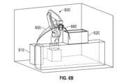
図6Bは、本開示の実施形態に係る、洗練された初期参照を用いて最適化動作計画で少数の経路の軌跡を反復計算したロボット600の図である。図6Bにおいて、最適化計算は洗練された初期参照経路650で開始した後に最終経路660への収束に到達するのに非常に少数の反復しか必要としない。少数の反復(経路650、660、及び一つの中間のみ)は、図4の曲線440上のドットを表している。洗練された初期参照経路650は最終経路660に非常に類似しているため、最適化計算は初期参照後たった2回の反復で収束する。図6Bは本開示に係る洗練された初期参照経路を用いる最適化動作計画技術に関連した効率を視覚的に示している。この効率は、先行技術の方法より大幅に短い計算時間をもたらし、ワーク毎に新たな経路を計算しなければならないアプリケーション用の実時間動作計画を可能にする。Figure 6B is a diagram of a
前述の議論を通して、種々のコンピュータ及び制御部を説明し暗示した。これらコンピュータ及び制御部のソフトウエアアプリケーション及びモジュールはプロセッサ及びメモリモジュールを有する一以上のコンピュータ装置上で実行されることを理解されたい。特に、これは前述した図1のロボット制御部110の中のプロセッサを含む。具体的には、制御部110の中のプロセッサは、先の開示を通じて、特にフローチャート200で説明した方法において最適化経路計画計算用の洗練された初期参照経路を提供するよう構成される。また、制御部110が単にロボット100を制御し、他のコンピュータが最適化経路計画計算用の洗練された初期参照経路を提供し使用するように構成される場合には、別のコンピュータが最適化動作計画を実行し、計算した経路を制御部110に提供することも可能である。Various computers and controllers have been described and implied throughout the preceding discussion. It should be understood that the software applications and modules of these computers and controllers execute on one or more computing devices having a processor and memory modules. In particular, this includes the processor in the
前述したように、洗練された初期参照経路を用いるロボット最適化動作計画技術用に開示した技術はロボット経路計画の速度と信頼性を改善する。開示した技術は、単純な初期参照経路を用いるときに経験したものより最適経路への非常に迅速な収束を提供し、迅速な収束は新たな経路をワーク毎に計算しなければならないアプリケーションにおいて経路計画を実時間で実行することを可能にする。As discussed above, the disclosed techniques for robot optimization motion planning using sophisticated initial reference paths improve the speed and reliability of robot path planning. The disclosed techniques provide much faster convergence to an optimal path than experienced when using simple initial reference paths, and the rapid convergence allows path planning to be performed in real time in applications where a new path must be calculated for each workpiece.
洗練された初期参照経路を用いるロボット最適化動作計画技術の多数の代表的な態様及び実施形態を前述してきたが、当業者は、修正、置換、追加、及びそれらサブコンビネーションを認識するであろう。従って、次に添付した請求の範囲及び次に紹介する請求の範囲は、それら真の精神及び範囲の中にあるとき、全ての斯かる修正、置換、追加、及びサブコンビネーションを含むと解釈されるよう意図している。
[構成1]
産業用ロボットの動作計画方法であって、前記方法は、
前記ロボットのツールの経路を計画するための、前記ツールの前記経路の開始点及び目標点を含む入力情報を提供することと、
以前計算した経路のリポジトリから候補経路を選択することと、前記候補経路を置換及び拡縮して最初点及び最終点が前記開始点及び前記目標点にそれぞれ一致した初期参照経路を生成することを含む、初期参照経路を生成することと、
目的関数を規定することと、等式制約として前記経路の前記開始点及び目標点を規定することと、を含む、プロセッサ及びメモリを有するコンピュータを用いてロボット動作最適化問題をモデル化することと、
前記最適化問題を解く際に最初の反復として前記初期参照経路を用いて、前記ツールの前記経路を生成するために前記ロボット動作最適化問題を前記コンピュータによって解くことと、
前記リポジトリに前記経路を記憶することと、
を含む、方法。
[構成2]
入力情報を提供することは前記ロボットの作業空間の中の障害物を規定する障害物データを提供することを更に含み、ロボット動作最適化問題をモデル化することは前記障害物データを用いて衝突回避不等式制約を規定することを含む、構成1に記載の方法。
[構成3]
前記衝突回避不等式制約は、前記ロボットの計算した姿勢毎にロボットと障害物の最短距離が予め規定した閾値を超えなければならないことである、構成2に記載の方法。
[構成4]
候補経路を選択することは、前記開始点及び前記目標点のそれぞれに対する前記候補経路の最初点及び最終点の近接度に基づいて前記候補経路を選択することを含む、構成1に記載の方法。
[構成5]
前記候補経路を選択することは、前記候補経路の解の質と、前記候補経路を計算する際に用いた障害物環境とのうちの少なくとも一方に基づいて前記候補経路を選択することを更に含む、構成4に記載の方法。
[構成6]
前記初期参照経路を規定するために前記候補経路を置換及び拡縮することは、前記開始点から前記候補経路の最初点までの第一偏差と前記目標点から前記候補経路の最終点までの第二偏差とを計算することと、前記候補経路の長さに沿って前記第一偏差及び前記第二偏差を比例して適用することにより前記初期参照経路上の点を計算することと、を含む、構成1に記載の方法。
[構成7]
前記初期参照経路上の点は次の式を用いて計算され、
qα=pα+(1-α)δ0+αδ1
ここで、qαは前記初期参照経路上の点であり、pαは前記候補経路上の点であり、δ0は前記第一偏差であり、δ1は前記第二偏差であり、αは前記候補経路に沿った、0から1の範囲の比例距離である、構成6に記載の方法。
[構成8]
ロボット動作最適化問題をモデル化することは、前記ロボットの関節毎のシステム動力学又は運動学方程式に基づいて等式制約を規定することと、予め規定された閾値を超えないロボット関節の回転速度、加速度、及び加加速度と、予め規定された閾値を超えないロボットツール中心点の速度、加速度、及び加加速度と、予め規定された制限を超えない関節位置とを含む不等式制約を規定することと、を更に含む、構成1に記載の方法。
[構成9]
前記動作最適化問題を解くことは、解が予め規定された収束基準に収束するまで前記動作最適化問題を反復して解くことを含む、構成1に記載の方法。
[構成10]
前記ツールに前記経路を追従させる前記ロボットの全ての関節の動作を計算することと、関節動作指令を前記ロボットに提供することと、を更に含む、構成1に記載の方法。
[構成11]
産業用ロボットの経路計画方法であって、前記方法は、
前記ロボットのツールの経路の開始点及び目標点を提供することと、以前計算した経路のリポジトリから候補経路を選択し、前記候補経路を置換及び拡縮することによって初期参照経路を生成して最初点及び最終点が前記開始点及び前記目標点にそれぞれ一致した初期参照経路を生成することと、前記ツールの前記経路を生成するために前記初期参照経路を最初の反復として用いてロボット動作最適化問題をモデル化して解くことと、前記経路を前記リポジトリに記憶することと、を含む、方法。
[構成12]
ロボット動作最適化問題をモデル化することは、前記ロボットの関節毎にシステム動力学又は運動学方程式に基づいて等式制約を規定することと、関節の位置、速度、加速度、及び加加速度の制限に基づいて不等式制約を規定することと、ロボット作業空間の障害物データに基づいて衝突回避不等式制約を規定することと、を更に含む、構成11に記載の方法。
[構成13]
産業用ロボット用の経路計画システムであって、前記システムは、
前記ロボットのツールの経路を計画するための、前記ツールの前記経路の開始点と目標点を含む入力情報を提供する手段と、
前記ロボットと通信しているコンピュータと、を備え、前記コンピュータは、
以前計算した経路のリポジトリから候補経路を選択することと、前記候補経路を置換及び拡縮して最初点及び最終点が前記開始点及び前記目標点にそれぞれ一致した初期参照経路を生成することとを含む、初期参照経路を生成することと、
目的関数を規定することと、等式制約として前記経路の前記開始点及び目標点を規定することと、を含む、ロボット動作最適化問題をモデル化することと、
前記最適化問題を解く際に最初の反復として前記初期参照経路を用いて、前記ツールの前記経路を生成するために前記ロボット動作最適化問題を解くことと、
前記リポジトリに前記経路を記憶することと、
を構成されたプロセッサ及びメモリを有する、システム。
[構成14]
入力情報を提供することは前記ロボットの作業空間の中の障害物を規定する障害物データを提供することを更に含み、ロボット動作最適化問題をモデル化することは前記障害物データを用いて衝突回避不等式制約を規定することを含み、前記衝突回避不等式制約は前記ロボットの計算した姿勢毎にロボットと障害物の最短距離が予め規定した閾値を超えなければならないことである、構成13に記載のシステム。
[構成15]
候補経路を選択することは、前記開始点及び前記目標点のそれぞれに対する前記候補経路の最初点及び最終点の近接度に基づいて前記候補経路を選択することを含む、構成13に記載のシステム。
[構成16]
候補経路を選択することは、前記候補経路の解の質と、前記候補経路を計算する際に用いた障害物環境とのうちの少なくとも一方に基づいて前記候補経路を選択することを更に含む、構成15に記載のシステム。
[構成17]
前記初期参照経路を規定するために前記候補経路を置換及び拡縮することは、前記開始点から前記候補経路の最初点までの第一偏差と前記目標点から前記候補経路の最終点までの第二偏差とを計算することと、前記候補経路の長さに沿って前記第一偏差及び前記第二偏差を比例して適用することにより前記初期参照経路上の点を計算することと、を含む、構成13に記載のシステム。
[構成18]
ロボット動作最適化問題をモデル化することは、前記ロボットの関節毎のシステム動力学又は運動学方程式に基づいて等式制約を規定することと、予め規定された閾値を超えないロボット関節の回転速度、加速度、及び加加速度と、予め規定された閾値を超えないロボットツール中心点の速度、加速度、及び加加速度と、予め規定された制限を超えない関節位置とを含む不等式制約を規定することと、を更に含む、構成13に記載のシステム。
[構成19]
前記動作最適化問題を解くことは、解が予め規定された収束基準に収束するまで前記動作最適化問題を反復して解くことを含む、構成13に記載のシステム。
[構成20]
前記コンピュータは更に、前記ツールに前記経路を追従させる前記ロボットの全ての関節の動作を計算することと、関節動作指令を前記ロボットに提供することと、を構成された、構成13に記載のシステム。 While numerous exemplary aspects and embodiments of the robot optimization motion planning technique using refined initial reference paths have been described above, those skilled in the art will recognize modifications, permutations, additions, and subcombinations thereof, and it is therefore intended that the following appended claims and hereafter presented claims be construed to include all such modifications, permutations, additions, and subcombinations as fall within their true spirit and scope.
[Configuration 1]
1. A motion planning method for an industrial robot, the method comprising:
providing input information for planning a path of the robotic tool, the input information including a start point and a destination point of the path of the tool;
generating an initial reference path, comprising selecting a candidate path from a repository of previously computed paths and permuting and scaling the candidate path to generate an initial reference path whose first and last points respectively coincide with the start point and the destination point;
modeling a robot motion optimization problem using a computer having a processor and memory, the problem including defining an objective function and defining the start point and the end point of the path as equality constraints;
solving, by the computer, the robot motion optimization problem to generate the path of the tool using the initial reference path as a first iteration in solving the optimization problem;
storing the path in the repository;
A method comprising:
[Configuration 2]
2. The method of
[Configuration 3]
3. The method of claim 2, wherein the collision avoidance inequality constraint is that for each computed pose of the robot, the minimum distance between the robot and an obstacle must exceed a predefined threshold.
[Configuration 4]
2. The method of
[Configuration 5]
5. The method of claim 4, wherein selecting the candidate route further comprises selecting the candidate route based on at least one of a solution quality of the candidate route and an obstacle environment used in calculating the candidate route.
[Configuration 6]
2. The method of
[Configuration 7]
The points on the initial reference path are calculated using the formula:
qα= pα+ (1-α) δ0+ αδ1
7. The method of configuration 6, wherein qαisa point on the initial reference path, pαisa point on the candidate path, δ0isthe first deviation, δ1isthe second deviation, and α is a proportional distance along the candidate path ranging from 0 to 1.
[Configuration 8]
2. The method of
[Configuration 9]
2. The method of
[Configuration 10]
2. The method of
[Configuration 11]
1. A path planning method for an industrial robot, the method comprising:
providing a start point and a destination point of a path of a tool of the robot; selecting a candidate path from a repository of previously computed paths and generating an initial reference path by permuting and scaling the candidate path to generate an initial reference path whose first and final points respectively coincide with the start point and the destination point; modeling and solving a robot motion optimization problem using the initial reference path as a first iteration to generate the path of the tool; and storing the path in the repository.
[Configuration 12]
12. The method of claim 11, wherein modeling the robot motion optimization problem further includes defining equality constraints based on system dynamics or kinematic equations for each joint of the robot, defining inequality constraints based on joint position, velocity, acceleration, and jerk limits, and defining collision avoidance inequality constraints based on obstacle data for the robot workspace.
[Configuration 13]
1. A path planning system for an industrial robot, the system comprising:
means for providing input information for planning a path of the robotic tool, the input information including a start point and a destination point of the path of the tool;
a computer in communication with the robot, the computer comprising:
generating an initial reference path, comprising selecting a candidate path from a repository of previously computed paths and permuting and scaling the candidate path to generate an initial reference path whose first and last points respectively coincide with the start point and the destination point;
Modeling a robot motion optimization problem, comprising: defining an objective function; and defining the start point and the end point of the path as equality constraints;
solving the robot motion optimization problem to generate the path of the tool using the initial reference path as a first iteration in solving the optimization problem;
storing the path in the repository;
A system having a processor and memory configured to:
[Configuration 14]
14. The system of configuration 13, wherein providing input information further includes providing obstacle data defining obstacles in a workspace of the robot, and modeling the robot motion optimization problem includes defining collision avoidance inequality constraints using the obstacle data, the collision avoidance inequality constraints being such that for each calculated pose of the robot, a minimum distance between the robot and an obstacle must exceed a predefined threshold.
[Configuration 15]
14. The system of claim 13, wherein selecting a candidate route comprises selecting the candidate route based on proximity of a first point and a last point of the candidate route to the start point and the destination point, respectively.
[Configuration 16]
16. The system of
[Configuration 17]
14. The system of claim 13, wherein permuting and scaling the candidate path to define the initial reference path includes calculating a first deviation from the start point to a first point of the candidate path and a second deviation from the destination point to a final point of the candidate path, and calculating a point on the initial reference path by proportionally applying the first deviation and the second deviation along a length of the candidate path.
[Configuration 18]
14. The system of configuration 13, wherein modeling the robot motion optimization problem further includes defining equality constraints based on system dynamics or kinematic equations for each joint of the robot, and defining inequality constraints including robot joint rotational velocities, accelerations, and jerk not exceeding predefined thresholds, robot tool center point velocities, accelerations, and jerk not exceeding predefined thresholds, and joint positions not exceeding predefined limits.
[Configuration 19]
14. The system of claim 13, wherein solving the motion optimization problem comprises iteratively solving the motion optimization problem until a solution converges to a predefined convergence criterion.
[Configuration 20]
14. The system of claim 13, wherein the computer is further configured to calculate motions of all joints of the robot that cause the tool to follow the path; and provide joint motion commands to the robot.
Claims (18)
Translated fromJapanese前記産業用ロボットのツールの経路を計画するための、前記ツールの前記経路の開始点及び目標点を含む入力情報を提供することと、
以前計算した経路のリポジトリから候補経路を選択することと、前記候補経路を置換及び拡縮して最初点及び最終点が前記開始点及び前記目標点にそれぞれ一致した初期参照経路を生成することを含む、初期参照経路を生成することと、
目的関数を規定することと、等式制約として前記経路の前記開始点及び目標点を規定することと、を含む、プロセッサ及びメモリを有するコンピュータを用いてロボット動作最適化問題をモデル化することと、
前記ロボット動作最適化問題を解く際に最初の反復として前記初期参照経路を用いて、前記ツールの前記経路を生成するために前記ロボット動作最適化問題を前記コンピュータによって解くことと、
前記リポジトリに前記経路を記憶することと、
を含み、
前記ロボット動作最適化問題を解くことは、解が予め規定された収束基準に収束するまで前記ロボット動作最適化問題を反復して解くことを含む、方法。 1. A methodfor planning a motion of an industrial robot, the method comprising the steps of:
providing input information for planning a path of a tool of theindustrial robot, the input information including a start point and a destination point of the path of the tool;
generating an initial reference path, comprising selecting a candidate path from a repository of previously computed paths and permuting and scaling the candidate path to generate an initial reference path whose first and last points respectively coincide with the start point and the destination point;
modeling a robot motion optimization problem using a computer having a processor and memory, the problem including defining an objective function and defining the start point and the end point of the path as equality constraints;
solving, by the computer,the robot motion optimization problem to generate the path of the tool using the initial reference path as a first iteration in solving the robot motion optimization problem;
storing the path in the repository;
Including,
The method, wherein solving the robot motion optimization problem includes iteratively solving the robot motion optimization problem until a solution converges to a predefined convergence criterion .
qα=pα+(1-α)δ0+αδ1
ここで、qαは前記初期参照経路上の点であり、pαは前記候補経路上の点であり、δ0は前記第一偏差であり、δ1は前記第二偏差であり、αは前記候補経路に沿った、0から1の範囲の比例距離である、請求項6に記載の方法。 The points on the initial reference path are calculated using the formula:
qα =pα + (1-α)δ0 +αδ1
7. The method of claim 6, whereinqα is a point on the initial reference path,pα is a point on the candidate path,δ0 is the first deviation,δ1 is the second deviation, and α is a proportional distance along the candidate path ranging from 0 to 1.
前記産業用ロボットのツールの経路を計画するための、前記ツールの前記経路の開始点及び目標点を含む入力情報を提供することと、
以前計算した経路のリポジトリから候補経路を選択することと、前記候補経路を置換及び拡縮して最初点及び最終点が前記開始点及び前記目標点にそれぞれ一致した初期参照経路を生成することを含む、初期参照経路を生成することと、
目的関数を規定することと、等式制約として前記経路の前記開始点及び目標点を規定することと、を含む、プロセッサ及びメモリを有するコンピュータを用いてロボット動作最適化問題をモデル化することと、
前記ロボット動作最適化問題を解く際に最初の反復として前記初期参照経路を用いて、前記ツールの前記経路を生成するために前記ロボット動作最適化問題を前記コンピュータによって解くことと、
前記リポジトリに前記経路を記憶することと、
を含み、
入力情報を提供することは前記産業用ロボットの作業空間の中の障害物を規定する障害物データを提供することを更に含み、ロボット動作最適化問題をモデル化することは前記障害物データを用いて衝突回避不等式制約を規定することを含み、
前記衝突回避不等式制約は、前記産業用ロボットの計算した姿勢毎に産業用ロボットと障害物の最短距離が予め規定した閾値を超えなければならないことである、方法。1. A method for planning a motion of an industrial robot, the method comprising the steps of:
providing input information for planning a path of a tool of the industrial robot, the input information including a start point and a destination point of the path of the tool;
generating an initial reference path, comprising selecting a candidate path from a repository of previously computed paths and permuting and scaling the candidate path to generate an initial reference path whose first and last points respectively coincide with the start point and the destination point;
modeling a robot motion optimization problem using a computer having a processor and memory, the problem including defining an objective function and defining the start point and the end point of the path as equality constraints;
solving, by the computer, the robot motion optimization problem to generate the path of the tool using the initial reference path as a first iteration in solving the robot motion optimization problem;
storing the path in the repository;
Including,
Providing input information further includes providing obstacle data defining obstacles in a workspace of the industrial robot, and modeling a robot motion optimization problem includes defining collision avoidance inequality constraints using the obstacle data;
The method, wherein the collision avoidance inequality constraint is that for each calculated pose of the industrial robot, the minimum distance between the industrial robot and an obstacle must exceed a predefined threshold.
前記産業用ロボットのツールの経路の開始点及び目標点を提供することと、以前計算した経路のリポジトリから候補経路を選択し、前記候補経路を置換及び拡縮することによって初期参照経路を生成して最初点及び最終点が前記開始点及び前記目標点にそれぞれ一致した初期参照経路を生成することと、プロセッサ及びメモリを有するコンピュータを用いて前記ツールの前記経路を生成するために前記初期参照経路を最初の反復として用いてロボット動作最適化問題をモデル化して解くことと、前記経路を前記リポジトリに記憶することと、を含み、
ロボット動作最適化問題をモデル化することは、前記産業用ロボットの関節毎にシステム動力学又は運動学方程式に基づいて等式制約を規定することと、関節の位置、速度、加速度、及び加加速度の制限に基づいて不等式制約を規定することと、ロボット作業空間の障害物データに基づいて衝突回避不等式制約を規定することと、を更に含む、方法。 1. A method forplanning a path for an industrial robot, the method comprising the steps of:
providing a start point and a destination point of a path of a tool ofthe industrial robot; selecting a candidate path from a repository of previously calculated paths and generating an initial reference path by permuting and scaling the candidate path to generate an initial reference path whose first and last points respectively coincide with the start point and the destination point; modeling and solving a robot motion optimization problem using the initial reference path as a first iteration to generate the path of the toolusing a computer having a processor and memory ; andstoring the path in the repository;
The method, wherein modeling a robot motion optimization problem further includes defining equality constraints based on system dynamics or kinematic equations for each joint of the industrial robot; defining inequality constraints based on joint position, velocity, acceleration, and jerk limits; and defining collision avoidance inequality constraints based on obstacle data of the robot workspace .
前記産業用ロボットのツールの経路を計画するための、前記ツールの前記経路の開始点と目標点を含む入力情報を提供する手段と、
前記産業用ロボットと通信しているコンピュータと、を備え、前記コンピュータは、
以前計算した経路のリポジトリから候補経路を選択することと、前記候補経路を置換及び拡縮して最初点及び最終点が前記開始点及び前記目標点にそれぞれ一致した初期参照経路を生成することとを含む、初期参照経路を生成することと、
目的関数を規定することと、等式制約として前記経路の前記開始点及び目標点を規定することと、を含む、ロボット動作最適化問題をモデル化することと、
前記ロボット動作最適化問題を解く際に最初の反復として前記初期参照経路を用いて、前記ツールの前記経路を生成するために前記ロボット動作最適化問題を解くことと、
前記リポジトリに前記経路を記憶することと、
を構成されたプロセッサ及びメモリを有し、
候補経路を選択することは、前記開始点及び前記目標点のそれぞれに対する前記候補経路の最初点及び最終点の近接度に基づいて前記候補経路を選択することを含む、システム。 1. A systemfor planning a path for an industrial robot, the system comprising:
means for providing input information for planning a path of a tool of saidindustrial robot, said input information including a start point and a destination point of said path of said tool;
a computer in communication with theindustrial robot, the computer comprising:
generating an initial reference path, comprising selecting a candidate path from a repository of previously computed paths and permuting and scaling the candidate path to generate an initial reference path whose first and last points respectively coincide with the start point and the destination point;
Modeling a robot motion optimization problem, comprising: defining an objective function; and defining the start point and the end point of the path as equality constraints;
solvingthe robot motion optimization problem to generate the path of the tool using the initial reference path as a first iteration in solving the robot motion optimization problem;
storing the path in the repository;
a processor and memory configuredto
The system, wherein selecting a candidate route includes selecting the candidate route based on proximity of a first point and a last point of the candidate route to the start point and the destination point, respectively .
Applications Claiming Priority (2)
| Application Number | Priority Date | Filing Date | Title |
|---|---|---|---|
| US16/839,720US11707843B2 (en) | 2020-04-03 | 2020-04-03 | Initial reference generation for robot optimization motion planning |
| US16/839,720 | 2020-04-03 |
Publications (2)
| Publication Number | Publication Date |
|---|---|
| JP2021175590A JP2021175590A (en) | 2021-11-04 |
| JP7635055B2true JP7635055B2 (en) | 2025-02-25 |
Family
ID=77749842
Family Applications (1)
| Application Number | Title | Priority Date | Filing Date |
|---|---|---|---|
| JP2021063281AActiveJP7635055B2 (en) | 2020-04-03 | 2021-04-02 | Initial reference generation for robot optimized motion planning. |
Country Status (4)
| Country | Link |
|---|---|
| US (1) | US11707843B2 (en) |
| JP (1) | JP7635055B2 (en) |
| CN (1) | CN113552877A (en) |
| DE (1) | DE102021107495A1 (en) |
Families Citing this family (22)
| Publication number | Priority date | Publication date | Assignee | Title |
|---|---|---|---|---|
| CN116507459A (en)* | 2020-11-11 | 2023-07-28 | 索尼集团公司 | Information processing equipment and cooking system |
| JP7567381B2 (en)* | 2020-11-11 | 2024-10-16 | 富士通株式会社 | Motion control program, motion control method, and motion control device |
| US20220152816A1 (en)* | 2020-11-13 | 2022-05-19 | Intrinsic Innovation Llc | Decentralized robotic operating environment optimization |
| US12339668B2 (en)* | 2020-12-09 | 2025-06-24 | Sony Group Corporation | Path planning device |
| JP7552442B2 (en)* | 2021-03-03 | 2024-09-18 | オムロン株式会社 | Robot attitude determination device, method, and program |
| US11945117B2 (en) | 2021-03-10 | 2024-04-02 | Samsung Electronics Co., Ltd. | Anticipating user and object poses through task-based extrapolation for robot-human collision avoidance |
| US12103185B2 (en)* | 2021-03-10 | 2024-10-01 | Samsung Electronics Co., Ltd. | Parameterized waypoint generation on dynamically parented non-static objects for robotic autonomous tasks |
| US11833691B2 (en) | 2021-03-30 | 2023-12-05 | Samsung Electronics Co., Ltd. | Hybrid robotic motion planning system using machine learning and parametric trajectories |
| CN113894795B (en)* | 2021-11-17 | 2023-11-28 | 青岛九维华盾科技研究院有限公司 | Industrial robot external shaft position optimization method |
| CN114035590B (en)* | 2021-12-20 | 2023-12-29 | 安徽省配天机器人集团有限公司 | Robot track planning method, device, equipment and medium |
| US12049007B2 (en)* | 2022-03-01 | 2024-07-30 | Mitsubishi Electric Research Laboratories, Inc. | System and method for robust robotic manipulation using chance constrained optimization |
| CN114625148B (en)* | 2022-03-23 | 2024-06-28 | 中国人民解放军空军军医大学 | Disinfection robot path planning method comprising model constraint and real-time error system |
| CN114764245A (en)* | 2022-04-19 | 2022-07-19 | 北京能工荟智机器人有限责任公司 | Unmanned inspection robot and control method thereof |
| DK181570B1 (en)* | 2022-07-06 | 2024-05-28 | Onrobot As | Method and system for generating a trajectory for a robotic arm and a tool attached to the robotic arm |
| CN115167466B (en)* | 2022-08-11 | 2024-07-19 | 西安交通大学 | Mobile robot standard control set local path planning method and system |
| WO2024227491A1 (en)* | 2023-05-02 | 2024-11-07 | Universal Robots A/S | Joint scaling of a robot arm trajectory |
| CN117742338B (en)* | 2023-12-26 | 2024-06-21 | 天津河工大先进装备研究院有限公司 | Curtain wall repair robot scheduling system based on images |
| CN118787444B (en)* | 2024-06-14 | 2025-08-15 | 中国科学院深圳先进技术研究院 | Robot-assisted fracture reduction path planning method and system |
| CN118952225B (en)* | 2024-10-14 | 2025-01-17 | 深圳市智绘科技有限公司 | Mechanical arm motion control method and device, electronic equipment and storage medium |
| CN119148727B (en)* | 2024-11-21 | 2025-02-18 | 美象信息科技有限公司 | Path obstacle avoidance method based on fuzzy matching camera video stream and probability cloud computing |
| CN119858162B (en)* | 2025-02-24 | 2025-09-23 | 华中科技大学 | Robot time optimal speed planning method and system based on two-step linear programming |
| CN120335455B (en)* | 2025-06-12 | 2025-09-12 | 贵州安融科技发展有限公司 | Intelligent inspection robot path optimization method and system based on edge reasoning model |
Citations (8)
| Publication number | Priority date | Publication date | Assignee | Title |
|---|---|---|---|---|
| JP2011167828A (en) | 2010-02-22 | 2011-09-01 | Sinfonia Technology Co Ltd | Conveying device |
| JP2012206225A (en) | 2011-03-30 | 2012-10-25 | Sinfonia Technology Co Ltd | Transporting system |
| JP2013193194A (en) | 2012-03-22 | 2013-09-30 | Toyota Motor Corp | Track generating apparatus, moving body, track generating method, and program |
| JP2018094677A (en) | 2016-12-13 | 2018-06-21 | ファナック株式会社 | Robot control device with learning facilitation function, and robot control method |
| JP2018167252A (en) | 2017-03-30 | 2018-11-01 | マツダ株式会社 | Coating method and coating applicator |
| DE102017129665B3 (en) | 2017-12-12 | 2019-01-24 | Pilz Gmbh & Co. Kg | Collision-free motion planning with closed kinematics |
| JP2019119041A (en) | 2017-12-28 | 2019-07-22 | 深セン市優必選科技股▲ふん▼有限公司Ubtech Pobotics Corp Ltd | Robot motion path planning method, apparatus, storage medium, and terminal device |
| JP2020040205A (en) | 2018-09-13 | 2020-03-19 | ピルツ ゲーエムベーハー アンド コー.カーゲー | Motion planning method and apparatus for manipulator collision avoidance |
Family Cites Families (33)
| Publication number | Priority date | Publication date | Assignee | Title |
|---|---|---|---|---|
| US4403281A (en)* | 1981-04-03 | 1983-09-06 | Cincinnati Milacron Industries, Inc. | Apparatus for dynamically controlling the tool centerpoint of a robot arm off a predetermined path |
| US6216058B1 (en)* | 1999-05-28 | 2001-04-10 | Brooks Automation, Inc. | System of trajectory planning for robotic manipulators based on pre-defined time-optimum trajectory shapes |
| CA2514204C (en)* | 2003-01-31 | 2015-12-15 | Thermo Crs Ltd. | Syntactic inferential motion planning method for robotic systems |
| JP4087841B2 (en)* | 2004-12-21 | 2008-05-21 | ファナック株式会社 | Robot controller |
| WO2008154932A1 (en)* | 2007-06-18 | 2008-12-24 | Syddansk Universitet | Determining a robot path |
| US20100114338A1 (en) | 2008-10-31 | 2010-05-06 | Gm Global Technology Operations, Inc. | Multi-goal path planning of welding robots with automatic sequencing |
| KR101667029B1 (en) | 2009-08-10 | 2016-10-17 | 삼성전자 주식회사 | Method and apparatus of path planing for a robot |
| KR20110015765A (en) | 2009-08-10 | 2011-02-17 | 삼성전자주식회사 | Robot route planning device and method |
| KR101732902B1 (en) | 2010-12-27 | 2017-05-24 | 삼성전자주식회사 | Path planning apparatus of robot and method thereof |
| CN104010774B (en) | 2011-09-15 | 2017-10-13 | 康富真信息技术股份有限公司 | System and method for automatically generating robot programs |
| JP5426722B2 (en) | 2012-05-24 | 2014-02-26 | ファナック株式会社 | Robot program change device |
| CN102752855B (en)* | 2012-08-01 | 2015-05-13 | 重庆大学 | Indoor personnel positioning system and method based on path rule and prediction |
| WO2014056533A1 (en) | 2012-10-11 | 2014-04-17 | Abb Technology Ltd | A method and an apparatus for automatically generating a collision free return program for returning a robot from a stop position to a predefined restart position |
| US8700307B1 (en)* | 2013-03-04 | 2014-04-15 | Mitsubishi Electric Research Laboratories, Inc. | Method for determining trajectories manipulators to avoid obstacles |
| US9764469B1 (en) | 2013-12-13 | 2017-09-19 | University Of South Florida | Generating robotic trajectories with motion harmonics |
| DE102015204641B4 (en) | 2014-06-03 | 2021-03-25 | ArtiMinds Robotics GmbH | Method and system for programming a robot |
| US9381643B2 (en)* | 2014-07-03 | 2016-07-05 | GM Global Technology Operations LLC | Dynamical system-based robot velocity control |
| US10105849B1 (en)* | 2015-07-14 | 2018-10-23 | Glen C Wernersbach | Manufacturing system having robotic apparatus |
| JP2017077609A (en) | 2015-10-21 | 2017-04-27 | ファナック株式会社 | Calibration device and calibration method for calibrating mechanism parameter of wrist part of robot |
| WO2017223061A1 (en)* | 2016-06-20 | 2017-12-28 | Hypertherm, Inc. | Systems and methods for planning paths to guide robots |
| US9981383B1 (en)* | 2016-08-02 | 2018-05-29 | X Development Llc | Real-time trajectory generation for actuators of a robot to reduce chance of collision with obstacle(s) |
| DE102016120763B4 (en) | 2016-10-31 | 2019-03-14 | Pilz Gmbh & Co. Kg | Method for collision-free motion planning |
| JP6998660B2 (en)* | 2017-02-21 | 2022-01-18 | 株式会社安川電機 | Robot simulator, robot system and simulation method |
| US10766140B2 (en) | 2017-04-13 | 2020-09-08 | Battelle Memorial Institute | Teach mode collision avoidance system and method for industrial robotic manipulators |
| EP3652642B1 (en)* | 2017-07-11 | 2022-06-22 | Telefonaktiebolaget LM Ericsson (Publ) | Methods and arrangements for robot device control in a cloud |
| US20190184561A1 (en)* | 2017-12-15 | 2019-06-20 | The Regents Of The University Of California | Machine Learning based Fixed-Time Optimal Path Generation |
| JP6823015B2 (en)* | 2018-07-17 | 2021-01-27 | ファナック株式会社 | Robot system |
| US10946519B1 (en)* | 2018-11-30 | 2021-03-16 | X Development Llc | Offline computation and caching of precalculated joint trajectories |
| US20200278686A1 (en)* | 2019-02-28 | 2020-09-03 | University Of South Carolina | Iterative Feedback Motion Planning |
| EP3993963B1 (en)* | 2019-08-23 | 2025-07-16 | Realtime Robotics, Inc. | Motion planning for robots to optimize velocity while maintaining limits on acceleration and jerk |
| CN110850807B (en)* | 2019-12-04 | 2021-04-27 | 广东博智林机器人有限公司 | Singular point avoiding method, device, equipment and medium |
| US12005585B2 (en)* | 2019-12-27 | 2024-06-11 | Intrinsic Innovation Llc | Offline robot planning with online adaptation |
| US12145277B2 (en)* | 2020-09-03 | 2024-11-19 | Fanuc Corporation | Framework of robotic online motion planning |
- 2020
- 2020-04-03USUS16/839,720patent/US11707843B2/enactiveActive
- 2021
- 2021-03-25DEDE102021107495.9Apatent/DE102021107495A1/enactivePending
- 2021-04-01CNCN202110357325.5Apatent/CN113552877A/enactivePending
- 2021-04-02JPJP2021063281Apatent/JP7635055B2/enactiveActive
Patent Citations (8)
| Publication number | Priority date | Publication date | Assignee | Title |
|---|---|---|---|---|
| JP2011167828A (en) | 2010-02-22 | 2011-09-01 | Sinfonia Technology Co Ltd | Conveying device |
| JP2012206225A (en) | 2011-03-30 | 2012-10-25 | Sinfonia Technology Co Ltd | Transporting system |
| JP2013193194A (en) | 2012-03-22 | 2013-09-30 | Toyota Motor Corp | Track generating apparatus, moving body, track generating method, and program |
| JP2018094677A (en) | 2016-12-13 | 2018-06-21 | ファナック株式会社 | Robot control device with learning facilitation function, and robot control method |
| JP2018167252A (en) | 2017-03-30 | 2018-11-01 | マツダ株式会社 | Coating method and coating applicator |
| DE102017129665B3 (en) | 2017-12-12 | 2019-01-24 | Pilz Gmbh & Co. Kg | Collision-free motion planning with closed kinematics |
| JP2019119041A (en) | 2017-12-28 | 2019-07-22 | 深セン市優必選科技股▲ふん▼有限公司Ubtech Pobotics Corp Ltd | Robot motion path planning method, apparatus, storage medium, and terminal device |
| JP2020040205A (en) | 2018-09-13 | 2020-03-19 | ピルツ ゲーエムベーハー アンド コー.カーゲー | Motion planning method and apparatus for manipulator collision avoidance |
Also Published As
| Publication number | Publication date |
|---|---|
| DE102021107495A1 (en) | 2021-10-07 |
| CN113552877A (en) | 2021-10-26 |
| US11707843B2 (en) | 2023-07-25 |
| US20210308865A1 (en) | 2021-10-07 |
| JP2021175590A (en) | 2021-11-04 |
Similar Documents
| Publication | Publication Date | Title |
|---|---|---|
| JP7635055B2 (en) | Initial reference generation for robot optimized motion planning. | |
| US12145277B2 (en) | Framework of robotic online motion planning | |
| US11813753B2 (en) | Collision avoidance motion planning method for industrial robot | |
| US11724387B2 (en) | Fast robot motion optimization with distance field | |
| Chen et al. | Collision-free motion planning for human-robot collaborative safety under cartesian constraint | |
| Xu et al. | Motion planning of manipulators for simultaneous obstacle avoidance and target tracking: An RNN approach with guaranteed performance | |
| Ata | Optimal trajectory planning of manipulators: a review | |
| CN108818530B (en) | Motion planning method of robotic arm grabbing and stacking pistons based on improved RRT algorithm | |
| JP7210201B2 (en) | Information processing method, program, recording medium, information processing device, robot system, article manufacturing method | |
| CN108621165A (en) | Industrial robot dynamic performance optimal trajectory planning method under obstacle environment | |
| Di Lillo et al. | Merging global and local planners: real-time replanning algorithm of redundant robots within a task-priority framework | |
| Nakhaeinia et al. | A behavior-based approach for collision avoidance of mobile robots in unknown and dynamic environments | |
| CN117340890A (en) | Robot motion trail control method | |
| CN118219260A (en) | A motion control method for a mobile robotic arm in a dynamic scene and its application | |
| Fujii et al. | Realtime trajectory smoothing with neural nets | |
| JP7747542B2 (en) | Dynamic Motion Planning System | |
| Zanchettin et al. | Near time-optimal and sensor-based motion planning for robotic manipulators | |
| Puiu et al. | Real-time collision avoidance for redundant manipulators | |
| Salmaninejad et al. | Motion path planning of two robot arms in a common workspace | |
| Steffens et al. | Continuous motion planning for service robots with multiresolution in time | |
| CN113492402B (en) | Fast robotic motion optimization with distance field | |
| Tam et al. | BOMP: Bin-Optimized Motion Planning | |
| JPWO2020145403A1 (en) | Control device | |
| JP7756141B2 (en) | Method and system for orbital path planning | |
| CN118163116B (en) | Robot control method, device and robot |
Legal Events
| Date | Code | Title | Description |
|---|---|---|---|
| A621 | Written request for application examination | Free format text:JAPANESE INTERMEDIATE CODE: A621 Effective date:20240306 | |
| A977 | Report on retrieval | Free format text:JAPANESE INTERMEDIATE CODE: A971007 Effective date:20240918 | |
| A131 | Notification of reasons for refusal | Free format text:JAPANESE INTERMEDIATE CODE: A131 Effective date:20241022 | |
| A521 | Request for written amendment filed | Free format text:JAPANESE INTERMEDIATE CODE: A523 Effective date:20241213 | |
| TRDD | Decision of grant or rejection written | ||
| A01 | Written decision to grant a patent or to grant a registration (utility model) | Free format text:JAPANESE INTERMEDIATE CODE: A01 Effective date:20250114 | |
| A61 | First payment of annual fees (during grant procedure) | Free format text:JAPANESE INTERMEDIATE CODE: A61 Effective date:20250212 | |
| R150 | Certificate of patent or registration of utility model | Ref document number:7635055 Country of ref document:JP Free format text:JAPANESE INTERMEDIATE CODE: R150 |