JP7634958B2 - Generation device, generation method, and program - Google Patents
Generation device, generation method, and programDownload PDFInfo
- Publication number
- JP7634958B2 JP7634958B2JP2020175734AJP2020175734AJP7634958B2JP 7634958 B2JP7634958 B2JP 7634958B2JP 2020175734 AJP2020175734 AJP 2020175734AJP 2020175734 AJP2020175734 AJP 2020175734AJP 7634958 B2JP7634958 B2JP 7634958B2
- Authority
- JP
- Japan
- Prior art keywords
- virtual viewpoint
- viewpoint image
- image
- generating device
- viewpoint
- Prior art date
- Legal status (The legal status is an assumption and is not a legal conclusion. Google has not performed a legal analysis and makes no representation as to the accuracy of the status listed.)
- Active
Links
Images


Classifications
- G—PHYSICS
- G06—COMPUTING OR CALCULATING; COUNTING
- G06T—IMAGE DATA PROCESSING OR GENERATION, IN GENERAL
- G06T15/00—3D [Three Dimensional] image rendering
- G06T15/10—Geometric effects
- G06T15/20—Perspective computation
- H—ELECTRICITY
- H04—ELECTRIC COMMUNICATION TECHNIQUE
- H04N—PICTORIAL COMMUNICATION, e.g. TELEVISION
- H04N13/00—Stereoscopic video systems; Multi-view video systems; Details thereof
- H04N13/20—Image signal generators
- H04N13/282—Image signal generators for generating image signals corresponding to three or more geometrical viewpoints, e.g. multi-view systems
- G—PHYSICS
- G06—COMPUTING OR CALCULATING; COUNTING
- G06T—IMAGE DATA PROCESSING OR GENERATION, IN GENERAL
- G06T15/00—3D [Three Dimensional] image rendering
- G06T15/50—Lighting effects
- G06T15/503—Blending, e.g. for anti-aliasing
- H—ELECTRICITY
- H04—ELECTRIC COMMUNICATION TECHNIQUE
- H04N—PICTORIAL COMMUNICATION, e.g. TELEVISION
- H04N13/00—Stereoscopic video systems; Multi-view video systems; Details thereof
- H04N13/20—Image signal generators
- H04N13/204—Image signal generators using stereoscopic image cameras
- H04N13/243—Image signal generators using stereoscopic image cameras using three or more 2D image sensors
- H—ELECTRICITY
- H04—ELECTRIC COMMUNICATION TECHNIQUE
- H04N—PICTORIAL COMMUNICATION, e.g. TELEVISION
- H04N13/00—Stereoscopic video systems; Multi-view video systems; Details thereof
- H04N13/20—Image signal generators
- H04N13/275—Image signal generators from 3D object models, e.g. computer-generated stereoscopic image signals
Landscapes
- Engineering & Computer Science (AREA)
- Multimedia (AREA)
- Signal Processing (AREA)
- Theoretical Computer Science (AREA)
- Physics & Mathematics (AREA)
- Computer Graphics (AREA)
- General Physics & Mathematics (AREA)
- Computing Systems (AREA)
- Geometry (AREA)
- Processing Or Creating Images (AREA)
- Image Generation (AREA)
Description
Translated fromJapanese本開示は、仮想視点画像を生成する技術に関するものである。This disclosure relates to technology for generating virtual viewpoint images.
近年、撮像領域の周囲に複数の撮像装置を配置して撮像を行い、それぞれの撮像装置から取得された複数の撮像画像を用いて、指定された視点(仮想視点)から見た画像(仮想視点画像)を生成する技術が注目されている。In recent years, a technology that captures images using multiple imaging devices arranged around an imaging area and generates an image (virtual viewpoint image) viewed from a specified viewpoint (virtual viewpoint) using the multiple captured images acquired from each imaging device has been attracting attention.
特許文献1には、被写体の三次元形状データを用いて生成される被写体の画像と、背景の画像とを合成することにより、仮想視点画像を生成する方法について記載されている。Patent document 1 describes a method for generating a virtual viewpoint image by synthesizing an image of a subject, which is generated using three-dimensional shape data of the subject, with an image of the background.
仮想視点画像上で表現される背景によっては、仮想視点画像において被写体が背景である床面や壁面に反射する様子を表現することで、リアリティ性を持たせることが求められている。しかしながら、特許文献1では、そのようなことは考慮されていない。Depending on the background depicted in the virtual viewpoint image, it is necessary to add a sense of reality by depicting how the subject is reflected on the floor or wall of the background in the virtual viewpoint image. However, this is not taken into consideration in Patent Document 1.
本開示は上記の課題に鑑みてなされたものである。その目的は、被写体の反射を表現可能な仮想視点画像の生成技術を提供することである。This disclosure has been made in consideration of the above problems. Its purpose is to provide a technology for generating a virtual viewpoint image that can represent the reflection of a subject.
本開示に係る生成手段は、複数の撮像装置が行う撮像により取得される複数の撮像画像および第1の仮想視点に基づいて生成される第1の仮想視点画像と、三次元空間に含まれる所定の面における表面の凹凸を示す情報とを取得する第1の取得手段と、前記複数の撮像画像と、前記第1の仮想視点に対し前記所定の面を挟むように配置される第2の仮想視点とに基づいて生成される、第2の仮想視点画像を取得する第2の取得手段と、前記第1の仮想視点画像と、前記情報に基づいてぼかし処理が行われた前記第2の仮想視点画像とに基づいて、前記第1の仮想視点に対応し、前記所定の面に前記複数の撮像装置により撮像される撮像空間に位置するオブジェクトが反射する状態を示す像を含む第3の仮想視点画像を生成する生成手段とを有することを特徴とする。 The generation means of the present disclosure is characterized in having a first acquisition means for acquiring a first virtual viewpoint image generated based on a plurality of captured images acquired by imaging performed by a plurality of imaging devicesand a first virtual viewpoint, and information indicating surface unevenness on a predetermined surface included in a three-dimensional space , a second acquisition means for acquiring a second virtual viewpoint image generated based on the plurality of captured images and a second virtual viewpoint arranged to sandwich the predetermined surfacewith respect to the first virtual viewpoint, anda generationmeans for generating a third virtual viewpoint image corresponding to the first virtual viewpoint and including an image indicating a state in which an object located in an imaging spacecaptured by the plurality of imaging devices is reflected on the predetermined surface, based on the first virtual viewpoint image and the second virtual viewpoint image subjected to a blurring process based on the information.
本開示によれば、被写体の反射を表現可能な仮想視点画像を生成することができる。According to the present disclosure, it is possible to generate a virtual viewpoint image that can represent the reflection of a subject.
以下、本開示の実施形態について、図面を参照しながら説明する。なお、以下の実施形態に記載される構成要素は、本開示の実施の形態の一例を示すものであり、本開示をそれらのみに限定するものではない。Embodiments of the present disclosure will be described below with reference to the drawings. Note that the components described in the following embodiments are examples of embodiments of the present disclosure, and the present disclosure is not limited to these.
(第1の実施形態)
本実施形態においては、被写体が背景に反射して映り込む様子を模した仮想視点画像を生成する生成装置について説明する。本実施形態における仮想視点画像は、自由視点映像とも呼ばれるものであるが、ユーザが自由に(任意に)指定した視点(仮想視点)に対応する画像に限定されず、例えば複数の候補からユーザが選択した視点に対応する画像なども仮想視点画像に含まれる。また、本実施形態では仮想視点の指定がユーザ操作により行われる場合を中心に説明するが、仮想視点の指定が画像解析の結果等に基づいて自動で行われてもよい。また、本実施形態では仮想視点画像が動画である場合を中心に説明するが、仮想視点画像は静止画であってもよい。 (First embodiment)
In this embodiment, a generating device that generates a virtual viewpoint image that imitates a subject being reflected on a background will be described. The virtual viewpoint image in this embodiment is also called a free viewpoint video, but is not limited to an image corresponding to a viewpoint (virtual viewpoint) freely (arbitrarily) specified by a user, and for example, an image corresponding to a viewpoint selected by a user from a plurality of candidates is also included in the virtual viewpoint image. In addition, in this embodiment, the case where the virtual viewpoint is specified by a user operation will be mainly described, but the virtual viewpoint may be automatically specified based on the result of image analysis, etc. In addition, in this embodiment, the case where the virtual viewpoint image is a moving image will be mainly described, but the virtual viewpoint image may be a still image.
図1は、本実施形態における生成装置10のハードウェア構成を説明するための図である。生成装置10は、CPU501、RAM502、ROM503、操作部504、出力部505、補助記憶装置506、I/F507、及び、バス508を有する。FIG. 1 is a diagram for explaining the hardware configuration of the generating
CPU501は、RAM502やROM503に格納されているコンピュータプログラムやデータを用いて生成装置10全体の制御を行う。即ち、CPU501は、生成装置10における各処理部として機能する。The
RAM502は、補助記憶装置506から読み出されるコンピュータプログラムやデータ、及び、I/F(インターフェース)507を介して外部から取得されるデータなどを一時的に記憶する。更に、RAM502は、CPU501が各種の処理を実行する際に用いるワークエリアを有する。即ち、RAM502は、例えば、フレームメモリとして割り当てられたり、その他の各種のエリアを適宜提供したりすることができる。RAM 502 temporarily stores computer programs and data read from
ROM503には、生成装置10の設定に関するデータや、ブートプログラムなどが格納されている。操作部504は、キーボード、マウス、及びジョイスティックなどにより構成される。生成装置10のユーザは、操作部504を操作することにより、各種の指示をCPU501に対して入力することができる。出力部505は、また出力部505は例えば液晶ディスプレイで構成され、CPU501による処理結果等を表示する。The
補助記憶装置506は、ハードディスクドライブ装置に代表される、情報記憶装置である。補助記憶装置506には、OS(オペレーティングシステム)や、生成装置10が有する各処理部の機能をCPU501に実現させるためのコンピュータプログラム等が保存される。補助記憶装置506に保存されているコンピュータプログラムやデータは、CPU501による制御に従って適宜、RAM502にロードされ、CPU501による処理対象となる。また、補助記憶装置506には、生成装置10が処理を行う対象の画像データ等が保存される。The
I/F507は、LANやインターネット等のネットワーク、投影装置や表示装置などの他の機器と接続され、情報の送受信を行う。例えば、生成装置10が外部の装置と有線で接続される場合には、通信用のケーブルがI/F507に接続される。生成装置10が外部の装置と無線通信する機能を有する場合には、I/F507はアンテナを備える。バス508は上述した各部をつないで情報を伝達する。The I/F 507 is connected to a network such as a LAN or the Internet, and to other devices such as a projection device or display device, and transmits and receives information. For example, when the generating
なお、図1に示す構成では、操作部504、出力部505、及び、補助記憶装置506が精鋭装置10の内部に含まれるが、これに限定されない。例えば、操作部504、出力部505、及び、補助記憶装置506のうち少なくともいずれかが他の装置として生成装置10の外部に接続される構成であってもよい。In the configuration shown in FIG. 1, the
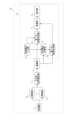
図2は、本実施形態における仮想視点画像を生成する生成システムの構成を説明するための図である。図1の生成システム20は、複数の撮像部1a、・・・1z、同期部2、三次元形状推定部3、蓄積部4、及び、生成装置10を有する。なお、図2における参照符号について、番号の後ろに付与したアルファベットのみが異なる符号は、同一機能を持つ装置の別インスタンスを示すものとする。例えば、撮像部1aと撮像部1zは同一の機能を持つ別インスタンスを示している。なお、同一の機能を持つとは、少なくとも特定の機能(撮像機能など)を有することを指すものであり、例えば撮像部1aと撮像部1zが有する機能及び性能の一部が異なっていてもよい。また、以下の説明において、撮像部1は、撮像部1a~1zの総称を表す。撮像部1の数は、任意に変更されてもよい。Figure 2 is a diagram for explaining the configuration of a generation system that generates a virtual viewpoint image in this embodiment. The generation system 20 in Figure 1 has multiple
複数の撮像部1は、例えばカメラなどの撮像装置である。複数の撮像部1は、被写体を囲むように設置され、被写体を複数の方向から撮像する。本実施形態において複数の撮像部1により撮像される被写体は、後述する三次元形状推定部3により三次元形状データが生成される対象のオブジェクトである。被写体は、例えば、人物、及び、人物が扱う道具などでありうる。複数の撮像部1は、撮像により得られた撮像画像を三次元形状推定部3に出力する。同期部2は、同期信号を生成し、複数の撮像部1に送信する。複数の撮像部1は、同期部2から受信した同期信号に基づいて、互いに同期して撮像を行う。The multiple imaging units 1 are imaging devices such as cameras. The multiple imaging units 1 are installed to surround a subject and capture images of the subject from multiple directions. In this embodiment, the subject captured by the multiple imaging units 1 is an object for which three-dimensional shape data is generated by the three-dimensional shape estimation unit 3 described below. The subject may be, for example, a person or a tool used by the person. The multiple imaging units 1 output captured images obtained by imaging to the three-dimensional shape estimation unit 3. The synchronization unit 2 generates a synchronization signal and transmits it to the multiple imaging units 1. The multiple imaging units 1 capture images in synchronization with each other based on the synchronization signal received from the synchronization unit 2.
三次元形状推定部3は、入力された複数の撮像画像を用いて、被写体の三次元形状を表す三次元形状データを生成する。本実施形態における三次元形状推定部3は、撮像画像における被写体の領域を抽出することにより得られるシルエット画像を生成する。また、三次元形状推定部3は、複数のシルエット画像を使用して、公知の技術である視体積交差法(shape-from-silhouette法)に基づく方法により、被写体の三次元形状データを生成する。なお、三次元形状の推定方法はこれに限定されず、他の手法が用いられてもよい。生成された被写体の三次元形状データは、撮像空間における被写体の位置を表す情報、及び、被写体の三次元形状を表す情報を含む。また、シルエット画像の生成は、三次元形状推定部3とは異なる装置で行われる構成であってもよい。三次元形状推定部3は、生成した被写体の三次元形状データ、及び、複数の撮像部1から取得された複数の撮像画像を、蓄積部4に出力する。The three-dimensional shape estimation unit 3 uses the input multiple captured images to generate three-dimensional shape data representing the three-dimensional shape of the subject. In this embodiment, the three-dimensional shape estimation unit 3 generates a silhouette image obtained by extracting the area of the subject in the captured image. The three-dimensional shape estimation unit 3 also uses the multiple silhouette images to generate three-dimensional shape data of the subject by a method based on the shape-from-silhouette method, which is a known technology. Note that the method of estimating the three-dimensional shape is not limited to this, and other methods may be used. The generated three-dimensional shape data of the subject includes information representing the position of the subject in the captured space and information representing the three-dimensional shape of the subject. The silhouette image may be generated by a device different from the three-dimensional shape estimation unit 3. The three-dimensional shape estimation unit 3 outputs the generated three-dimensional shape data of the subject and the multiple captured images obtained from the multiple imaging units 1 to the storage unit 4.
蓄積部4は、三次元形状推定部3から出力された複数の撮像画像及び三次元形状データを蓄積する。また、蓄積部4は、三次元形状データにより表される被写体とは異なるオブジェクト(以下、背景という)の三次元形状データを蓄積する。ここでいう背景は、例えば、壁や床などでありうる。本実施形態における背景の三次元形状データは、ポリゴンメッシュにより表現されるものとし、三次元空間における座標の情報を有する。背景の三次元形状データは、以下の方法により生成される。例えば、被写体の三次元形状データと同様に、撮像部1が撮像を行うことにより得られる撮像画像に基づいて、背景の三次元形状データが生成される。このとき、背景の三次元形状データの生成に使用される撮像画像は、被写体とは異なる時間又は場所において行われた撮像に基づく撮像画像であってもよい。また、例えば、被写体が存在する撮像空間には存在しない仮想的なオブジェクトをコンピュータグラフィック(CG)を用いて表現することにより、仮想的な空間を模した背景の三次元形状データが生成されてもよい。また、背景の三次元形状データには、例えばメッシュの反射率及び表面の形状等、各メッシュの材質情報が含まれる。なお、メッシュの材質情報は上記に限定されず、反射率及び表面の形状の少なくとも一方に関する情報が含まれていてもよいし、反射率及び表面の形状以外の情報がさらに含まれていてもよい。また、反射率及び表面の形状に関する情報は、実空間における背景に対応するオブジェクトの反射率及び表面の形状を表す情報であってもよいし、ユーザが予め設定した情報であってもよい。例えば、背景がCGを使用して生成された仮想的なオブジェクトである場合は、ユーザによって反射率及び表面の形状が設定される。The storage unit 4 stores a plurality of captured images and three-dimensional shape data output from the three-dimensional shape estimation unit 3. The storage unit 4 also stores three-dimensional shape data of an object (hereinafter referred to as background) different from the subject represented by the three-dimensional shape data. The background here may be, for example, a wall or a floor. The three-dimensional shape data of the background in this embodiment is represented by a polygon mesh and has coordinate information in three-dimensional space. The three-dimensional shape data of the background is generated by the following method. For example, like the three-dimensional shape data of the subject, the three-dimensional shape data of the background is generated based on the captured image obtained by the imaging unit 1 performing imaging. At this time, the captured image used to generate the three-dimensional shape data of the background may be an image based on imaging performed at a time or place different from that of the subject. Also, for example, by expressing a virtual object that does not exist in the imaging space in which the subject exists using computer graphics (CG), three-dimensional shape data of the background that imitates a virtual space may be generated. Also, the three-dimensional shape data of the background includes material information of each mesh, such as the reflectance and surface shape of the mesh. Note that the mesh material information is not limited to the above, and may include information on at least one of the reflectance and the surface shape, or may further include information other than the reflectance and the surface shape. Furthermore, the information on the reflectance and the surface shape may be information that represents the reflectance and the surface shape of an object that corresponds to the background in real space, or may be information that is preset by the user. For example, if the background is a virtual object generated using CG, the reflectance and the surface shape are set by the user.
本実施形態においては、被写体が背景に反射して映り込む様子を模した仮想視点画像の生成が行われる。この際に、被写体が反射する面(以下、反射面という)を特定する必要がある。本実施形態における反射面は、反射する被写体の像を重畳する領域であり、実際に反射する面でなくてもよい。すなわち、本実施形態で説明する技術を使用することにより、実際に撮像される反射しない床面や、CGを使用して生成された仮想的な床面等であっても被写体が反射する様子を表現することが可能である。例えば、反射面は、金属表面やガラスなど、光沢をもった面である。あるいは、反射面は、仮想的にそのような光沢をもった面をテクスチャとして背景で表現した仮想的な面であってもよい。典型的には、反射面は、鏡面反射が生じる面、あるいは鏡面反射が生じるようなテクスチャで表現される仮想的な面である。In this embodiment, a virtual viewpoint image is generated that mimics the subject being reflected in the background. At this time, it is necessary to identify the surface on which the subject is reflected (hereinafter, referred to as the reflective surface). The reflective surface in this embodiment is an area on which the image of the reflective subject is superimposed, and does not have to be an actual reflective surface. In other words, by using the technology described in this embodiment, it is possible to express the subject being reflected even on a non-reflective floor surface that is actually captured, or a virtual floor surface generated using CG. For example, the reflective surface is a glossy surface such as a metal surface or glass. Alternatively, the reflective surface may be a virtual surface in which such a glossy surface is virtually expressed as a texture in the background. Typically, the reflective surface is a surface on which specular reflection occurs, or a virtual surface expressed with a texture that causes specular reflection.
本実施形態における背景の三次元形状データは、三次元座標の情報として、ユーザが予め設定した三次元空間における反射面の座標を含むものとする。したがって、反射面は、背景の三次元形状データを参照することにより特定が可能である。また、例えば、反射率の情報に基づき、反射が発生する領域が反射面として特定されてもよい。以降の説明においては、反射面を特定するための三次元座標の情報、及び、反射面が有する反射率等の情報を、反射面情報という。なお、背景の三次元形状データの形態は上述したものに限定されない。また、反射面における反射率は一様でなくてもよく、反射面上の位置よって、異なる反射率を有していてもよい。The three-dimensional shape data of the background in this embodiment includes, as three-dimensional coordinate information, the coordinates of the reflecting surface in three-dimensional space that is set in advance by the user. Therefore, the reflecting surface can be identified by referring to the three-dimensional shape data of the background. Also, for example, an area where reflection occurs may be identified as the reflecting surface based on reflectance information. In the following description, the three-dimensional coordinate information for identifying the reflecting surface and information such as the reflectance of the reflecting surface are referred to as reflecting surface information. Note that the form of the three-dimensional shape data of the background is not limited to that described above. Also, the reflectance of the reflecting surface does not have to be uniform, and the reflectance may differ depending on the position on the reflecting surface.
また、蓄積部4は、背景の三次元形状データに色付けをするための背景テクスチャデータを蓄積する。具体的には、背景テクスチャデータは各ポリゴンメッシュに貼り付ける画像である。また、蓄積部4は、複数の撮像部1の設置位置、姿勢及び光学特性などのカメラパラメータを蓄積する。The storage unit 4 also stores background texture data for coloring the background three-dimensional shape data. Specifically, the background texture data is an image that is pasted onto each polygon mesh. The storage unit 4 also stores camera parameters such as the installation positions, orientations, and optical characteristics of the multiple imaging units 1.
なお、複数の撮像画像全体が蓄積部4に記憶される構成でなくてもよい。例えば、撮像画像のうち、三次元形状データの色付けに必要な領域が抽出された画像が蓄積部4に記憶される構成でもよい。蓄積部4は、蓄積しているデータを、生成装置10からの指示に応じて生成装置10に送信する。The storage unit 4 does not necessarily have to store all of the captured images. For example, the storage unit 4 may store images from which areas necessary for coloring the three-dimensional shape data have been extracted from the captured images. The storage unit 4 transmits the stored data to the generating
次に、生成装置10が有する機能構成を、図2~4を用いて説明する。生成装置10は、仮想視点入力部5、反射視点生成部6、第一の画像生成部7a、第二の画像生成部7b、重畳部8、及び、表示部9を有する。Next, the functional configuration of the
仮想視点入力部5は、仮想視点を決定するための入力を受け付ける。仮想視点入力部5は、例えば、ユーザが操作部504を操作することにより得られる入力情報を受け付け、受け付けた入力情報に基づいて決定される仮想視点情報を第一の画像生成部7a及び反射視点生成部6に入力する。ここで、仮想視点情報とは、仮想視点の位置及び仮想視点からの視線方向を示すパラメータを含む情報である。また、仮想視点情報は、生成される仮想視点画像における時刻を特定するためのパラメータを含む。さらに、仮想視点情報は、仮想視点の画角(視野の広さ)を示すパラメータを含んでいてもよい。仮想視点情報は、少なくとも仮想視点の位置及び仮想視点からの視線方向を示すパラメータが含まれる情報であるものとする。なお、仮想視点入力部5は、例えば、補助記憶装置506及び外部に接続された記憶装置等に記憶された仮想視点情報を取得する構成であってもよい。The virtual viewpoint input unit 5 accepts input for determining a virtual viewpoint. For example, the virtual viewpoint input unit 5 accepts input information obtained by the user operating the
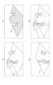
第一の画像生成部7aは、仮想視点入力部5から取得された仮想視点情報に基づいて、仮想視点画像を生成する。第一の画像生成部7aは、仮想視点情報に基づいて、仮想視点画像の生成に必要なデータを蓄積部4から取得する。第一の画像生成部7aは、取得したデータのうち、背景の三次元形状データと背景テクスチャデータとを使用して、仮想視点画像における背景を描画する。また、第一の画像生成部7aは、取得したデータのうち、被写体の三次元形状データと撮像画像とを使用して、仮想視点画像における被写体を描画する。このとき、撮像画像に基づいて被写体の三次元形状データに色付けすることにより、仮想視点から見た被写体が描画される。結果として、第一の画像生成部7aは、図3(a)示すような仮想視点映像を生成し出力する。The first
反射視点生成部6は、蓄積部4から背景の三次元形状データを取得し、取得した三次元形状データに含まれる情報に基づいて反射面を特定する。反射面とは、例えば、図3(a)における反射面200である。本実施形態においては、反射面は、三次元形状データに含まれる反射面の三次元座標を示す情報に基づいて特定される。また、反射視点生成部6は、仮想視点入力部5から取得される仮想視点情報と、特定した反射面とに基づいて、反射視点を生成する。反射視点は、反射面及び指定された仮想視点と所定の位置関係を有する仮想視点であり、反射面の位置に基づいて、指定された仮想視点の位置を変換させることにより取得される。反射視点生成部6は、反射視点を表す仮想視点情報(以下、反射視点情報という)を第二の画像生成部7bに入力する。The reflection viewpoint generating unit 6 acquires three-dimensional shape data of the background from the storage unit 4, and identifies a reflection surface based on information included in the acquired three-dimensional shape data. The reflection surface is, for example, the
第二の画像生成部7bは、反射視点情報と、蓄積部4から取得したデータとに基づいて、反射視点に対応する仮想視点画像(以下、反射視点画像という)を生成する。例えば、図3(a)に示す仮想視点画像に対応する反射視点画像は、図3(b)のような画像となる。反射視点及び反射視点画像の詳細な生成方法については後述する。The second
重畳部8は第一の画像生成部7aにより生成された仮想視点画像、第二の画像生成部7bにより生成された反射視点画像、及び、反射面情報に基づいて、仮想視点画像と反射視点情報とを重畳する。結果として、図3(d)に示すような、被写体の反射を模した仮想視点画像が生成される。表示部9は、重畳部8により生成された仮想視点画像を表示する。The superimposing unit 8 superimposes the virtual viewpoint image generated by the first
次に、生成装置10が行う処理を、図3~5を用いて説明する。図5は、生成装置10が行う処理を説明するためのフローチャートである。図5に示す処理は、生成装置10が有するCPU501がROM503または補助記憶装置506に記憶されたプログラムを読み出して実行することにより実行される。また、図5に示す処理は、ユーザにより仮想視点を指定するための操作が行われると開始される。Next, the processing performed by the generating
S101において、仮想視点入力部5は、操作部504に対して行われる、仮想視点の位置及び仮想視点からの視線方向を指定するための入力操作を受け付ける。また、仮想視点入力部5は、受け付けた入力操作に基づいて決定される仮想視点情報を、第一の画像生成部7a及び反射視点生成部6に送信する。ここでは、図4(a)における仮想視点300が、仮想視点として決定されるものとする。In S101, the virtual viewpoint input unit 5 accepts an input operation performed on the
S102において、第一の画像生成部7aは、取得した仮想視点情報に基づいて、仮想視点画像の生成に必要なデータとして、撮像画像、被写体の三次元形状データ及び背景の三次元形状データを、蓄積部4から取得する。S103において、第一の画像生成部7a及び反射視点生成部6は、蓄積部4から背景の三次元形状データを取得し、取得した三次元形状データに含まれる情報に基づいて反射面を特定する。ここでは、図3(a)における反射面200が特定される。In S102, the first
次に、第一の画像生成部7aが行う処理S104~S106と、反射視点生成部6及び第二の画像生成部7bが行う処理S107~S109について説明する。S104~S106における処理と、S107~S109における処理は、並行して行うことができる。Next, we will explain the processes S104 to S106 performed by the first
S104において、第一の画像生成部7aは、撮像画像及び仮想視点情報に基づいて、被写体の三次元形状データ及び背景の三次元形状データの色付け(レンダリング)を行う。S105において、第一の画像生成部7aは、レンダリングにより、被写体及び背景が描画された仮想視点画像を生成する。ここでは、図4(a)の仮想視点300に対応する仮想視点画像として、図3(a)が生成される。第一の画像生成部7aは、生成した仮想視点画像を、重畳部8に送信する。In S104, the first
S106において、第一の画像生成部7aは、生成した仮想視点画像のうち、反射面に対応する領域を抽出した画像(以下、反射面画像という)を生成する。反射面画像は、例えば、図3(c)に示すような、反射面の領域から被写体の領域を除いた画像である。反射面画像は、例えば以下の方法により生成される。第一の画像生成部7aは、S103において取得した反射面情報を使用して、反射面内が所定の画素値(例えば、1)になるようにレンダリングを行う。また、第一の画像生成部7aは、被写体と、反射面以外の背景とを、反射面とは異なる画素値(例えば、0)となるようにレンダリングを行う。この結果、図3(c)に示すように、被写体を除いた反射面の領域が所定の色でレンダリングされた反射面画像が生成される。第一の画像生成部7aは、生成した反射面画像を、重畳部8に送信する。In S106, the first
S107において、反射視点生成部6は、仮想視点入力部5から取得される仮想視点情報に基づいて、反射視点情報を生成する。ここでは、図4(a)における仮想視点300を、反射面200に対して反転させた反射視点301が生成される。すなわち、反射視点301は、仮想視点300の位置及び仮想視点300からの視線方向のそれぞれを反射面に対して反転させた仮想視点である。In S107, the reflected viewpoint generating unit 6 generates reflected viewpoint information based on the virtual viewpoint information acquired from the virtual viewpoint input unit 5. Here, a
反射視点生成部6が反射視点を生成する処理を、図8を使用して説明する。図8(a)は、仮想カメラの姿勢を説明するための図である。ここでは、便宜上、仮想視点を仮想的なカメラ(以下、仮想カメラという)に置き換えて説明する。仮想視点の位置、及び視線方向は、それぞれ仮想カメラの位置、及び姿勢に対応する。仮想カメラの姿勢は、水平方向における仮想カメラの回転角度(パン)、垂直方向における仮想カメラの回転角度(チルト)、及び、光軸方向における仮想カメラの回転角度(ロール)により表される。The process by which the reflected viewpoint generating unit 6 generates a reflected viewpoint will be explained using FIG. 8. FIG. 8(a) is a diagram for explaining the attitude of the virtual camera. For convenience, the virtual viewpoint will be replaced with a virtual camera (hereinafter referred to as a virtual camera) for explanation. The position and line of sight of the virtual viewpoint correspond to the position and attitude of the virtual camera, respectively. The attitude of the virtual camera is represented by the rotation angle of the virtual camera in the horizontal direction (pan), the rotation angle of the virtual camera in the vertical direction (tilt), and the rotation angle of the virtual camera in the optical axis direction (roll).
図8(b)は、仮想視点及び反射視点の一例を示す図である。図8(b)の例では、仮想視点300の位置及び仮想視点からの視線方向を表すパラメータとして、(x、y、z、p、t、0°)が設定されている。ここで、x、y、zは、それぞれxyz座標系で表される三次元空間における仮想視点300のz座標、y座標、z座標の値である。また、p、t、0°は、それぞれ図8(a)で説明した仮想視点300のパン、チルト、ロールの角度の値である。パン、チルト、ロールの角度は、それぞれの基準方向(例えばx軸、y軸、z軸)からの回転角として表される。ここで、反射面を表す座標がz=0であるものとする。反射視点生成部6は、反射面(z=0)に対して仮想視点300の面対称の位置になるように、反射視点301の位置を決定する。この結果、反射視点301のx座標、y座標、z座標の値は、それぞれx、y、-zとなる。また、反射視点生成部6は、反射面(z=0)に基づいて、反射視点301からの視線方向を決定する。このとき、反射視点生成部6は、パン、チルト、ロールの順番で視線方向を変更する。反射視点301のパンの値は、仮想視点300のパンの値と同一となる。また、反射視点301のチルトの値は、仮想視点300のチルトの値を反転させた値となる。また、反射視点301のロールの値は、0°から180°に変換される。結果として、反射視点301を表すパラメータは、(x、y、-z、p、-t、180°)となる。このように、反射視点301の位置は、仮想視点300の位置の反射面に対する面対称の位置にある。また、反射視点301からの視線方向は、反射面と仮想視点300からの視線方向とによる交点において、反射面と交わる視線方向である。つまり、反射視点301からの視線方向と、仮想視点300からの視線方向は、反射面上にある同一位置で交わる。なお、反射視点301の位置は、仮想視点300の位置の反射面に対する面対称の位置に基づいて設定されていてもよく、仮想視点300の位置の反射面に対する面対称の位置からずれていてもよい。また、反射視点301からの視線方向と反射面との交点は、反射面と仮想視点300からの視線方向とによる交点とずれていてもよい。つまり、反射視点301を表すパラメータが、(x、y、-z、p、-t、180°)がある程度ずれていてもよい。8B is a diagram showing an example of a virtual viewpoint and a reflection viewpoint. In the example of FIG. 8B, (x, y, z, p, t, 0°) are set as parameters representing the position of the
以上説明した方法により、反射視点を表すパラメータ(反射視点情報)が生成される。なお、図8の例では反射面がz=0である場合を示しているが、z=0以外の反射面に対しても、反射面の三次元位置に基づいて各パラメータの変換を行うことができる。なお、上述した方法においては、ロールの値が0ではない場合に、変換の計算が煩雑になりうる。したがって、ロール方向の回転を行う場合は、重畳部8が後段で生成した仮想視点画像が回転するように制御されてもよい。反射視点生成部6は、生成した反射視点情報を、第二の画像生成部7bに送信する。The method described above generates parameters (reflection viewpoint information) that represent the reflection viewpoint. Note that the example in FIG. 8 shows a case where the reflection surface is z=0, but for reflection surfaces other than z=0, each parameter can be converted based on the three-dimensional position of the reflection surface. Note that in the above-mentioned method, if the roll value is not 0, the conversion calculations can become complicated. Therefore, when performing rotation in the roll direction, the superimposition unit 8 may be controlled to rotate the virtual viewpoint image generated in the subsequent stage. The reflection viewpoint generation unit 6 transmits the generated reflection viewpoint information to the second
S108において、第二の画像生成部7bは、反射面情報及び反射視点情報に基づいて、反射視点画像を生成する。ここで、図3(b)に示す反射視点画像の生成方法について説明する。第二の画像生成部7bは、被写体の形状データ及び反射視点情報に基づいて、反射視点から見た被写体の色をレンダリングする。このとき、第二の画像生成部7bは、反射面情報を使用して、反射面に対応する領域内のみレンダリングを行う。反射視点画像としては、反射面に反射する被写体のみを描画すればよいため、反射面内のレンダリングのみを行うことにより、不要なレンダリング処理を削減することができる。またこのとき、第二の画像生成部7bは、反射面のレンダリングは行わない。なお、本実施形態における第二の画像生成部7bは、反射面に反射する被写体のみをレンダリングする構成とするが、反射面に反射する背景もさらにレンダリングする構成でもよい。In S108, the second
ここで、反射視点301から見たときの被写体の位置関係は、図4(c)に示すように左右が反転している。したがって、S109において、第二の画像生成部7bは、S108において反射面内のレンダリングを行うことにより得られた画像を左右反転する。これにより、第二の画像生成部7bは、図3(b)に示す反射視点画像を生成する。第二の画像生成部7bは、生成した反射視点画像を、重畳部8に送信する。Here, the positional relationship of the subject when viewed from the
S110において、重畳部8は、仮想視点画像、反射面画像、及び、反射視点画像に基づいて、図3(d)に示すような被写体の反射を模した仮想視点画像を生成する。重畳部8が生成する仮想視点画像は、仮想視点入力部5により取得された仮想視点情報が表す仮想視点に対応する仮想視点画像である。図3(d)に示す仮想視点画像は、以下のように生成される。重畳部8は、第二の画像生成部7bから取得した反射視点画像(図3(b))のうち、反射面画像(図3(c))によって表される反射面202に対応する領域を抽出する。また、重畳部8は、抽出した領域を仮想視点画像(図3(a))に重畳することにより、図3(d)に示す仮想視点画像を生成する。この仮想視点画像は、反射面において撮像空間に位置するオブジェクトが反射する状態を示す像を含んでいる。また、撮像空間に位置するオブジェクトのうち、第一の画像生成部7aにより生成された仮想視点画像には含まれていないオブジェクトであっても、第二の画像生成部7bにより生成される仮想視点画像により含まれることがある。その場合、重畳部8により生成される仮想視点画像には、そのオブジェクトが反射面において反射している状態を示す像を含むことができる。このtめ、よりリアリティのある画像を得ることができる。In S110, the superimposing unit 8 generates a virtual viewpoint image simulating the reflection of the subject as shown in FIG. 3(d) based on the virtual viewpoint image, the reflecting surface image, and the reflected viewpoint image. The virtual viewpoint image generated by the superimposing unit 8 is a virtual viewpoint image corresponding to the virtual viewpoint represented by the virtual viewpoint information acquired by the virtual viewpoint input unit 5. The virtual viewpoint image shown in FIG. 3(d) is generated as follows. The superimposing unit 8 extracts an area corresponding to the reflecting
なお、重畳部8は、反射視点画像を仮想視点画像に重畳する際に、反射視点画像に対して所定の画像処理を施すことにより、より現実味のある反射を再現することができる。例えば、重畳部8は、反射面情報に含まれる反射率に基づいて、反射視点画像の透過率またはブレンド率の少なくとも一方を変化させる処理を行ったうえで仮想視点画像に重畳する。反射視点画像の透過率は、仮想視点画像に反射視点画像を重畳する際の反射視点画像の画素値の割合を決定するパラメータである。透過率が大きいほど、画素値の割合が小さくなる。また、ブレンド率は、仮想視点画像と反射視点画像とを合成する際の各画像の画素値の割合を決定するパラメータである。反射視点画像のブレンド率が高いほど、反射視点画像の画素値の割合が大きくなり、仮想視点画像の画素値の割合は小さくなる。When the superimposing unit 8 superimposes the reflected viewpoint image on the virtual viewpoint image, the superimposing unit 8 can reproduce a more realistic reflection by performing a predetermined image processing on the reflected viewpoint image. For example, the superimposing unit 8 performs processing to change at least one of the transmittance or blending ratio of the reflected viewpoint image based on the reflectance included in the reflection surface information, and then superimposes it on the virtual viewpoint image. The transmittance of the reflected viewpoint image is a parameter that determines the ratio of pixel values of the reflected viewpoint image when the reflected viewpoint image is superimposed on the virtual viewpoint image. The higher the transmittance, the smaller the ratio of pixel values. The blending ratio is a parameter that determines the ratio of pixel values of each image when the virtual viewpoint image and the reflected viewpoint image are combined. The higher the blending ratio of the reflected viewpoint image, the larger the ratio of pixel values of the reflected viewpoint image and the smaller the ratio of pixel values of the virtual viewpoint image.
例えば、重畳部8は、画像処理を施す前の反射視点画像を基準として、反射面情報に含まれる反射率が高いほど、反射視点画像の透過率を低くする処理、及び、ブレンド率を大きくする処理の少なくとも一方を行う。For example, the superimposition unit 8 uses the reflected viewpoint image before image processing as a reference and performs at least one of the following processes: a process of lowering the transmittance of the reflected viewpoint image and a process of increasing the blending ratio as the reflectance included in the reflective surface information increases.
また例えば、重畳部8は、背景の三次元形状データに含まれる、背景の凹凸などの表面形状を表す情報に基づいて、反射視点画像にぼかしや変形を加える処理を行ったうえで仮想視点画像に重畳する。For example, the superimposing unit 8 performs processing to blur or distort the reflected viewpoint image based on information contained in the three-dimensional shape data of the background that represents the surface shape of the background, such as unevenness, and then superimposes it on the virtual viewpoint image.
また、例えば、仮想視点画像に描画された反射面200において、輝度が高い部分は反射視点画像の重畳割合を低く、輝度が低い部分は反射視点画像の重畳割合を高くする。この処理により、暗い色の反射面には被写体が相対的に濃く反射し、明るい色の反射面には被写体が相対的に薄く反射する、又は反射しない様子を模擬することができる。この処理においては、例えば、重畳部8は輝度に関する所定の閾値を参照し、仮想視点画像における反射面の輝度が所定の閾値よりも高い場合と低い場合とに応じて、反射視点画像の画素値を変更する。また例えば、重畳部8は、反射面の輝度と反射視点画像の画素値の割合とを対応付けたテーブルを参照し、反射面の輝度に応じて反射視点画像の画素値を変更してもよい。Also, for example, in the
なお、上述した反射視点画像に対する種々の画像処理は、第二の画像生成部7bで行われてもよい。The various image processing operations for the reflected viewpoint image described above may be performed by the second
S111において、重畳部8は、生成した仮想視点画像を、表示部9に表示させる。上述したS101~S111における処理により、被写体の反射を模した仮想視点画像が生成される。なお、仮想視点画像が動画である場合は、動画フレームごとにS101~S110の処理が繰り返される。例えば、動画のフレームレートが60fps(frame per second)である場合、1/60秒ごとにS101~S111の処理が繰り返される。In S111, the superimposing unit 8 causes the display unit 9 to display the generated virtual viewpoint image. A virtual viewpoint image that mimics the reflection of the subject is generated by the processes in S101 to S111 described above. Note that if the virtual viewpoint image is a video, the processes in S101 to S110 are repeated for each video frame. For example, if the frame rate of the video is 60 fps (frames per second), the processes in S101 to S111 are repeated every 1/60th of a second.
なお、仮想視点入力部5から取得される仮想視点情報が表す仮想視点が、反射面の裏側(例えば、反射する床面よりも下)に位置する場合に反射視点画像が生成されると、以下のような問題が発生する。すなわち、重畳部8において生成される仮想視点画像は、撮像部1では撮像されない床面の裏側に被写体が反射するような不自然な仮想視点画像となってしまう。したがって、仮想視点が特定の空間に位置する場合は、反射視点生成部6は反射視点情報の出力を行わないようにする。特定の空間は、例えば、仮想視点画像に描画される三次元空間のうち、反射面の裏側に接する空間である。反射面の表裏は、背景の三次元形状データに含まれるポリゴンメッシュの法線情報に基づいて特定される。すなわち、法線の方向と逆方向が、メッシュの裏側となる。本実施形態における仮想視点画像の生成では、被写体が存在する空間に反射面の表側が接するように背景の三次元形状データが生成される。したがって、特定の空間は、反射面に対して被写体の存在しない空間であるということができる。When the virtual viewpoint represented by the virtual viewpoint information acquired from the virtual viewpoint input unit 5 is located behind the reflecting surface (for example, below the reflecting floor surface), the following problem occurs when a reflected viewpoint image is generated. That is, the virtual viewpoint image generated by the superimposition unit 8 becomes an unnatural virtual viewpoint image in which the subject is reflected on the back side of the floor surface that is not captured by the imaging unit 1. Therefore, when the virtual viewpoint is located in a specific space, the reflected viewpoint generation unit 6 does not output the reflected viewpoint information. The specific space is, for example, a space that is in contact with the back side of the reflecting surface in the three-dimensional space depicted in the virtual viewpoint image. The front and back of the reflecting surface are identified based on the normal information of the polygon mesh included in the three-dimensional shape data of the background. That is, the reverse direction of the normal direction is the back side of the mesh. In the generation of the virtual viewpoint image in this embodiment, the three-dimensional shape data of the background is generated so that the front side of the reflecting surface is in contact with the space in which the subject exists. Therefore, it can be said that the specific space is a space in which no subject exists with respect to the reflecting surface.
反射視点生成部6は、仮想視点が特定の空間(反射面に対して被写体が存在しない空間)に位置する場合は、反射視点情報の出力を行わないようにする。また、第一の画像生成部7aは、反射面を除いて被写体及び背景のレンダリングを行う。これにより、第二の画像生成部7bによる反射映像生成を抑止し、重畳部8において不自然な反射映像を重畳することを抑制することができる。When the virtual viewpoint is located in a specific space (a space in which the subject does not exist relative to the reflective surface), the reflected viewpoint generating unit 6 does not output reflected viewpoint information. Furthermore, the first
以上説明した方法により、仮想視点画像において被写体の反射を表現することが可能となる。また、被写体の反射を模した画像の生成には、例えばレイトレーシング法を用いることも考えられるが、その方法は、1画素ずつ光線の経路を計算する必要があり、処理負荷が大きく高速な処理が困難である。それに比べ、上述した方法によれば、2つの仮想視点画像の合成による簡便な方法を用いることで、ハードウェアの処理負荷が軽減され、高速な処理が可能となる。The method described above makes it possible to express the reflection of a subject in a virtual viewpoint image. In addition, while it is possible to use, for example, a ray tracing method to generate an image that mimics the reflection of a subject, this method requires calculating the path of a ray for each pixel, which imposes a large processing load and makes high-speed processing difficult. In contrast, the method described above uses a simple method of synthesizing two virtual viewpoint images, which reduces the processing load on the hardware and enables high-speed processing.
(第1の実施形態の変形例)
上述した第1の実施形態の第二の画像生成部7bは、図5のS108において反射面内のみをレンダリングする。しかしながら、必ずしもこの方法に限定するものでない。第二の画像生成部7bは、例えば、反射視点画像として、図4(b)に示すように反射視点から見た被写体の全体をレンダリングする。そのうえで、重畳部8は、反射面情報202に基づいて、反射面200に対応する領域を反射視点画像から抽出し、仮想視点画像に重畳する構成としてもよい。この場合も第1の実施形態で示したものと同様の仮想視点画像が得られる。ただし、第二の画像生成部7bは、反射視点画像の生成の際に反射面内のみをレンダリングするほうが処理量を少なくすることができる。 (Modification of the first embodiment)
The second
また、上述した第1の実施形態では、背景の三次元形状データに含まれる反射面200は一つであるとして説明したが、反射面が複数あってもよい。例えば、背景の三次元形状データにおいて床面と壁面の二つの反射面がある場合には、反射視点生成部6は、床面に対応する反射視点と、壁面に対応する反射視点とを順次生成する。第二の画像生成部7bは、反射視点生成部6において生成された2つの反射視点に対応する反射視点画像を順次生成する。重畳部8は、生成された2つの反射視点画像を仮想視点画像に重畳する。これにより、複数の反射面が存在する場合の被写体の反射を模した仮想視点画像が生成される。反射面が3つ以上存在する場合にも、同様に生成が可能である。このとき、複数の第二の画像生成部7bを備える構成とし、複数の第二の画像生成部7bのそれぞれが並行して反射視点画像を生成する構成としてもよい。In the above-mentioned first embodiment, the 3D shape data of the background includes one
また、上述した第1の実施形態においては、反射面が平面である場合について説明したが、反射面が曲面であってもよい。反射面が曲面である場合、反射視点生成部6及び第二の画像生成部7bは、曲面を複数の平面に近似したうえで、上述した方法と同様に反射視点の生成及び反射視点画像の生成を行うことが可能である。In the first embodiment described above, the reflective surface is a flat surface, but the reflective surface may be a curved surface. When the reflective surface is a curved surface, the reflective viewpoint generating unit 6 and the second
また、上述した第1の実施形態では、重畳部8が、生成した仮想視点画像を表示部9に出力し表示する構成として説明したが、必ずしもこれに限定するものではない。重畳部8は、例えば、生成した仮想視点画像を画像データファイルとして出力する構成であってもよい。In the above-described first embodiment, the superimposition unit 8 is configured to output the generated virtual viewpoint image to the display unit 9 and display it, but this is not necessarily limited to this. For example, the superimposition unit 8 may be configured to output the generated virtual viewpoint image as an image data file.
(第2の実施形態)
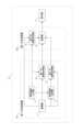
本実施形態における仮想視点画像を生成する生成システム21の構成を、図6を使用して説明する。本システムは第一の生成装置601と第二の生成装置602とを有する。第一の生成装置601は、蓄積部5、仮想視点入力部5、反射視点生成部6、第一の画像生成部7a、及び、第二の画像生成部7bを有する。なお、蓄積部4は、第一の生成装置601の外部に接続される装置であってもよい。また、第二の生成装置602は、第三の画像生成部7c及び重畳部8を有する。本実施形態においては、第1の実施形態と同一の名称及び符号の処理部は、第1の実施形態と同様の機能を有するものとする。 Second Embodiment
The configuration of a
本実施形態においては、第一の生成装置601において、被写体のみの仮想視点画像が生成され、第二の生成装置602において、第一の生成装置601において生成された仮想視点画像に背景をさらにレンダリングした仮想視点画像が生成される。図7を使用して、生成システム21が行う処理について説明する。In this embodiment, a
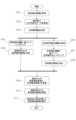
S701~S708の処理は、第一の生成装置601において行われる処理である。S701において、仮想視点入力部5は、操作部504に対して行われる、仮想視点の位置及び仮想視点からの視線方向を指定するための入力操作を受け付ける。また、仮想視点入力部5は、受け付けた入力操作に基づいて決定される仮想視点情報を、反射視点生成部6、第一の画像生成部7a、及び、第三の画像生成部7cに送信する。The processing of S701 to S708 is performed by the
S702において、第一の画像生成部7aは、取得した仮想視点情報に基づいて、仮想視点画像の生成に必要なデータとして、撮像画像及び被写体の三次元形状データを、蓄積部4から取得する。S703において、第一の画像生成部7aは、蓄積部4から、反射面情報を取得する。なお、本実施形態においては、背景は主に第二の生成装置602によりレンダリングされるため、ここで取得されるのは反射面の位置を特定可能な情報のみでよい。なお、蓄積部4は、第一の生成装置601に含まれず、異なる装置に含まれていてもよい。In S702, the first
S704において、第一の画像生成部7aは、仮想視点情報と、蓄積部4から取得したデータとに基づいて、被写体のレンダリングを行う。この結果、S705において、被写体のみの仮想視点画像が生成される。第一の画像生成部7aは、生成した被写体のみの仮想視点画像を、重畳部8に送信する。In S704, the first
S706において、反射視点生成部6は、反射面情報と、仮想視点情報とに基づいて、反射視点情報を生成する。反射視点情報の生成方法は、第1の実施形態と同様である。S707において、第二の画像生成部7bは、反射面情報と、反射視点情報とに基づいて、反射面内の被写体をレンダリングする。この結果、S708において、反射視点画像が生成される。反射視点画像の生成方法についても、第1の実施形態と同様である。第二の画像生成部7bは、生成した反射視点画像を、重畳部8に送信する。ここまでが、第一の生成装置601において行われる処理である。In S706, the reflected viewpoint generating unit 6 generates reflected viewpoint information based on the reflecting surface information and the virtual viewpoint information. The method of generating the reflected viewpoint information is the same as in the first embodiment. In S707, the second
S709~S711の処理は、第二の生成装置602において行われる処理である。S709において、第三の画像生成部7cは、仮想視点情報に基づいて、蓄積部4から背景の三次元形状データを取得し、背景をレンダリングすることにより得られる背景のみの仮想視点画像を生成する。また、重畳部8は、生成された背景のみの仮想視点画像と、第二の画像生成部7bから取得した反射視点画像とを重畳する。重畳部8は、反射視点画像を重畳する場合、第1の実施形態と同様に、反射視点画像のぼかし、変形、及び、重畳時の画素値の割合の変更等の画像処理を施したうえで重畳を行う。The processes of S709 to S711 are performed by the
S709において、重畳部8は、S709で生成された仮想視点画像に、S705で生成された被写体のみの仮想視点画像を重畳する。このとき、重畳部8は、被写体の距離情報と、背景の距離情報とを画素ごとに比較し、仮想視点の位置との距離が近い方の色を描画する。すなわち、重畳部8は、仮想視点と被写体との距離が、仮想視点と背景との距離よりも近い場合は、被写体のみの仮想視点画像の画素値を描画する。また、重畳部8は、仮想視点と被写体との距離が、仮想視点と背景との距離よりも遠い場合は、背景のみの仮想視点画像の画素値を描画する。結果として、重畳部8は、図3(d)に示すような、被写体の反射を模した仮想視点画像を生成する。S711において、重畳部8は、生成した仮想視点画像を表示部9に表示させる。In S709, the superimposing unit 8 superimposes the virtual viewpoint image of only the subject generated in S705 on the virtual viewpoint image generated in S709. At this time, the superimposing unit 8 compares the distance information of the subject and the distance information of the background for each pixel, and draws the color of the one closer to the position of the virtual viewpoint. That is, when the distance between the virtual viewpoint and the subject is closer than the distance between the virtual viewpoint and the background, the superimposing unit 8 draws the pixel value of the virtual viewpoint image of only the subject. Also, when the distance between the virtual viewpoint and the subject is farther than the distance between the virtual viewpoint and the background, the superimposing unit 8 draws the pixel value of the virtual viewpoint image of only the background. As a result, the superimposing unit 8 generates a virtual viewpoint image that mimics the reflection of the subject, as shown in FIG. 3(d). In S711, the superimposing unit 8 causes the display unit 9 to display the generated virtual viewpoint image.
本実施形態に示すような構成とすることで、被写体の仮想視点画像及び反射視点画像の生成と、背景の仮想視点画像及びその他の画像編集処理とを異なる装置で分担して行うことが可能となる。この構成は、映像制作の際に、撮像を行って被写体の映像を生成した後に、時間をかけて背景の作り込みや映像編集の処理を行うことができるという効果がある。The configuration shown in this embodiment makes it possible to share the generation of the virtual viewpoint image and reflected viewpoint image of the subject with the generation of the virtual viewpoint image and other image editing processes of the background, among different devices. This configuration has the advantage that, during video production, after capturing an image of the subject and generating it, it is possible to take time to create the background and edit the video.
なお、本実施形態においては、第二の生成装置602が、背景の三次元形状データを蓄積部4から取得するものとしたが、これに限定されない。第二の生成装置602は、装置の内部又は外部に接続される、蓄積部4とは異なる記憶装置から三次元形状データを取得する構成とすることができる。この構成の場合、蓄積部4は背景の三次元形状データのすべてを記憶する必要がなく、被写体の三次元形状データ及び反射面情報を記憶するのみでよい。In this embodiment, the
(その他の実施形態)
本開示は、上述の実施形態の1以上の機能を実現するプログラムを、ネットワーク又は記憶媒体を介してシステム又は装置に供給し、そのシステム又は装置のコンピュータにおける1つ以上のプロセッサーがプログラムを読出し実行する処理でも実現可能である。また、1以上の機能を実現する回路(例えば、ASIC)によっても実現可能である。 Other Embodiments
The present disclosure can also be realized by a process in which a program for implementing one or more of the functions of the above-described embodiments is supplied to a system or device via a network or a storage medium, and one or more processors in a computer of the system or device read and execute the program. The present disclosure can also be realized by a circuit (e.g., ASIC) for implementing one or more of the functions.
10 生成装置
7a 第一の画像生成部
7b 第二の画像生成部
8 重畳部 10
Claims (18)
Translated fromJapanese前記複数の撮像画像と、前記第1の仮想視点に対し前記所定の面を挟むように配置される第2の仮想視点とに基づいて生成される、第2の仮想視点画像を取得する第2の取得手段と、
前記第1の仮想視点画像と、前記情報に基づいてぼかし処理が行われた前記第2の仮想視点画像とに基づいて、前記第1の仮想視点に対応し、前記所定の面に前記複数の撮像装置により撮像される撮像空間に位置するオブジェクトが反射する状態を示す像を含む第3の仮想視点画像を生成する生成手段と
を有することを特徴とする生成装置。 a first acquisition means for acquiring a plurality of captured images acquired by imaging performed by a plurality of imaging devices, a first virtual viewpoint image generated based on a first virtual viewpoint, and information indicating surface irregularities on a predetermined surface included in a three-dimensional space ;
a second acquisition means for acquiring a second virtual viewpoint image generated based on the plurality of captured images and a second virtual viewpoint disposed on either side of the predetermined plane with respectto the first virtual viewpoint;
and a generation means for generating a third virtual viewpoint image based onthe first virtual viewpoint image and the second virtual viewpoint imagethat has been blurred based on the information , the third virtual viewpoint image corresponding to the first virtual viewpoint and including an image showing a state in which an object located in an imaging spaceimaged by the multiple imaging devices is reflected on the specified surface.
前記所定の処理は、前記面情報に含まれる反射率に基づいて、前記第2の仮想視点画像の画素値を変更する処理であることを特徴とする請求項11に記載の生成装置。 the surface information includes information representing a reflectance of the predetermined surface,
The generating device according to claim 11 , wherein the predetermined processing is processing for changing pixel values of the second virtual viewpoint image based on a reflectance included in the surface information.
前記生成手段は、前記第1の仮想視点画像と、前記複数の第2の仮想視点画像とに基づいて、前記第1の仮想視点に対応する第3の仮想視点画像を生成する
ことを特徴とする請求項1乃至15のいずれか1項に記載の生成装置。 the second acquisition means, when there are a plurality of the predetermined surfaces, acquires a plurality of second virtual viewpoint images corresponding to the plurality of predetermined surfaces, respectively;
The generating device according to any one of claims 1 to 15, characterized in that the generating means generates a third virtual viewpoint image corresponding to the first virtual viewpoint based on the first virtual viewpoint image and the plurality ofsecond virtual viewpoint images.
前記複数の撮像画像と、前記第1の仮想視点に対し前記所定の面を挟むように配置される第2の仮想視点とに基づいて生成される、第2の仮想視点画像を取得する第2の取得工程と、
前記第1の仮想視点画像と、前記情報に基づいてぼかし処理が行われた前記第2の仮想視点画像とに基づいて、前記第1の仮想視点に対応し、前記所定の面に前記複数の撮像装置により撮像される撮像空間に位置するオブジェクトが反射する状態を示す像を含む第3の仮想視点画像を生成する生成工程と
を有することを特徴とする生成方法。 a first acquisition step of acquiring a plurality of captured images acquired by imaging performed by a plurality of imaging devices, a first virtual viewpoint image generated based on a first virtual viewpoint, and information indicating surface irregularities on a predetermined surface included in a three-dimensional space ;
a second acquisition step of acquiring a second virtual viewpoint image generated based on the plurality of captured images and a second virtual viewpoint disposed on either side of the predetermined plane with respectto the first virtual viewpoint;
and generating a third virtual viewpoint image based onthe firstvirtual viewpoint image and the second virtual viewpoint image that has been blurred based on the information , the third virtual viewpoint image corresponding to the first virtual viewpoint and including an image showing a state in which an object located in an imaging spaceimaged by the multiple imaging devices is reflected on the specified surface.
Priority Applications (3)
| Application Number | Priority Date | Filing Date | Title |
|---|---|---|---|
| JP2020175734AJP7634958B2 (en) | 2020-10-20 | 2020-10-20 | Generation device, generation method, and program |
| US17/504,031US12238266B2 (en) | 2020-10-20 | 2021-10-18 | Generation apparatus, generation method, and storage medium |
| EP21203527.3AEP3989174A1 (en) | 2020-10-20 | 2021-10-19 | Generation apparatus, generation method, and program |
Applications Claiming Priority (1)
| Application Number | Priority Date | Filing Date | Title |
|---|---|---|---|
| JP2020175734AJP7634958B2 (en) | 2020-10-20 | 2020-10-20 | Generation device, generation method, and program |
Publications (2)
| Publication Number | Publication Date |
|---|---|
| JP2022067171A JP2022067171A (en) | 2022-05-06 |
| JP7634958B2true JP7634958B2 (en) | 2025-02-25 |
Family
ID=78592416
Family Applications (1)
| Application Number | Title | Priority Date | Filing Date |
|---|---|---|---|
| JP2020175734AActiveJP7634958B2 (en) | 2020-10-20 | 2020-10-20 | Generation device, generation method, and program |
Country Status (3)
| Country | Link |
|---|---|
| US (1) | US12238266B2 (en) |
| EP (1) | EP3989174A1 (en) |
| JP (1) | JP7634958B2 (en) |
Citations (1)
| Publication number | Priority date | Publication date | Assignee | Title |
|---|---|---|---|---|
| JP2017212592A (en) | 2016-05-25 | 2017-11-30 | キヤノン株式会社 | Controller, control method, and program |
Family Cites Families (9)
| Publication number | Priority date | Publication date | Assignee | Title |
|---|---|---|---|---|
| JPH09319891A (en)* | 1996-06-03 | 1997-12-12 | Sega Enterp Ltd | Image processing apparatus and processing method thereof |
| KR101419044B1 (en)* | 2013-06-21 | 2014-07-11 | 재단법인 실감교류인체감응솔루션연구단 | Method, system and computer-readable recording medium for displaying shadow of 3d virtual object |
| JP6429829B2 (en) | 2016-05-25 | 2018-11-28 | キヤノン株式会社 | Image processing system, image processing apparatus, control method, and program |
| JP2019003320A (en)* | 2017-06-13 | 2019-01-10 | キヤノン株式会社 | Image generating apparatus, image generating method, and program |
| CN110998669B (en)* | 2017-08-08 | 2023-12-08 | 索尼公司 | Image processing apparatus and method |
| US10812770B2 (en)* | 2017-09-13 | 2020-10-20 | Canon Kabushiki Kaisha | Image processing system, image processing apparatus, image processing method, and program |
| JP7080613B2 (en)* | 2017-09-27 | 2022-06-06 | キヤノン株式会社 | Image processing equipment, image processing methods and programs |
| US10885701B1 (en)* | 2017-12-08 | 2021-01-05 | Amazon Technologies, Inc. | Light simulation for augmented reality applications |
| JP7328116B2 (en)* | 2019-10-11 | 2023-08-16 | トヨタ自動車株式会社 | parking assist device |
- 2020
- 2020-10-20JPJP2020175734Apatent/JP7634958B2/enactiveActive
- 2021
- 2021-10-18USUS17/504,031patent/US12238266B2/enactiveActive
- 2021-10-19EPEP21203527.3Apatent/EP3989174A1/enactivePending
Patent Citations (1)
| Publication number | Priority date | Publication date | Assignee | Title |
|---|---|---|---|---|
| JP2017212592A (en) | 2016-05-25 | 2017-11-30 | キヤノン株式会社 | Controller, control method, and program |
Also Published As
| Publication number | Publication date |
|---|---|
| US12238266B2 (en) | 2025-02-25 |
| US20220124302A1 (en) | 2022-04-21 |
| JP2022067171A (en) | 2022-05-06 |
| EP3989174A1 (en) | 2022-04-27 |
Similar Documents
| Publication | Publication Date | Title |
|---|---|---|
| EP3827299B1 (en) | Mixed reality system with virtual content warping and method of generating virtual content using same | |
| US11210838B2 (en) | Fusing, texturing, and rendering views of dynamic three-dimensional models | |
| AU2018236457B2 (en) | Mixed reality system with virtual content warping and method of generating virtual content using same | |
| JP7166484B1 (en) | Generate new frames with rendered and unrendered content from the previous eye | |
| CN109660783A (en) | Virtual reality parallax correction | |
| CA3054617A1 (en) | Mixed reality system with multi-source virtual content compositing and method of generating virtual content using same | |
| EP2089852A1 (en) | Methods and systems for color correction of 3d images | |
| JP7353782B2 (en) | Information processing device, information processing method, and program | |
| US20130194254A1 (en) | Image processing apparatus, image processing method and program | |
| JP2023153534A (en) | Image processing apparatus, image processing method, and program | |
| JP7476511B2 (en) | Image processing system, image processing method and program | |
| JP7634958B2 (en) | Generation device, generation method, and program | |
| CN113570697A (en) | Shadow rendering method and device based on model prebaking and readable storage medium | |
| JP2017059041A (en) | Image processing apparatus, image processing method, and program | |
| JP7447429B2 (en) | Image processing system, image processing method and program | |
| CN118827936A (en) | Auxiliary image display method, device, medium and electronic equipment for operating machinery | |
| CN112565623A (en) | Dynamic image display system | |
| JP2001118074A (en) | Three-dimensional image creation method, three-dimensional image creation device, and program recording medium | |
| JP5865092B2 (en) | Image processing apparatus, image processing method, and program | |
| US6633291B1 (en) | Method and apparatus for displaying an image | |
| JP2011198138A (en) | Comic creation support device, comic creation support method, and program | |
| Güssefeld et al. | Are reflectance field renderings appropriate for optical flow evaluation? | |
| JP2022064148A (en) | Image processing device, image processing method | |
| JP2014010806A (en) | Light source information extraction device, light source information extraction method, and light source information extraction program | |
| 奥屋武志 | Real-Time Rendering Method for Reproducing the Features of Cel Animations |
Legal Events
| Date | Code | Title | Description |
|---|---|---|---|
| A621 | Written request for application examination | Free format text:JAPANESE INTERMEDIATE CODE: A621 Effective date:20231013 | |
| RD01 | Notification of change of attorney | Free format text:JAPANESE INTERMEDIATE CODE: A7421 Effective date:20231213 | |
| A977 | Report on retrieval | Free format text:JAPANESE INTERMEDIATE CODE: A971007 Effective date:20240808 | |
| A131 | Notification of reasons for refusal | Free format text:JAPANESE INTERMEDIATE CODE: A131 Effective date:20240820 | |
| A521 | Request for written amendment filed | Free format text:JAPANESE INTERMEDIATE CODE: A523 Effective date:20241011 | |
| TRDD | Decision of grant or rejection written | ||
| A01 | Written decision to grant a patent or to grant a registration (utility model) | Free format text:JAPANESE INTERMEDIATE CODE: A01 Effective date:20250114 | |
| A61 | First payment of annual fees (during grant procedure) | Free format text:JAPANESE INTERMEDIATE CODE: A61 Effective date:20250212 | |
| R150 | Certificate of patent or registration of utility model | Ref document number:7634958 Country of ref document:JP Free format text:JAPANESE INTERMEDIATE CODE: R150 |