JP7633886B2 - Power measurement system, power measurement device, power measurement method and program - Google Patents
Power measurement system, power measurement device, power measurement method and programDownload PDFInfo
- Publication number
- JP7633886B2 JP7633886B2JP2021097579AJP2021097579AJP7633886B2JP 7633886 B2JP7633886 B2JP 7633886B2JP 2021097579 AJP2021097579 AJP 2021097579AJP 2021097579 AJP2021097579 AJP 2021097579AJP 7633886 B2JP7633886 B2JP 7633886B2
- Authority
- JP
- Japan
- Prior art keywords
- input
- power
- current
- unit
- power factor
- Prior art date
- Legal status (The legal status is an assumption and is not a legal conclusion. Google has not performed a legal analysis and makes no representation as to the accuracy of the status listed.)
- Active
Links
Images


Landscapes
- Remote Monitoring And Control Of Power-Distribution Networks (AREA)
Description
Translated fromJapanese本開示は電力計測システム、電力計測機器、電力計測方法及びプログラムに関し、より詳細には、負荷に消費される電力を計測する電力計測システム、電力計測機器、電力計測方法及びプログラムに関する。This disclosure relates to a power measurement system, a power measurement device, a power measurement method, and a program, and more specifically to a power measurement system, a power measurement device, a power measurement method, and a program that measure the power consumed by a load.
特許文献1に記載の電力計測システムは、処理部と、通信部と、を備える。処理部は、回路に流れる電流を検出する電流センサの検出結果に基づいて、回路の電力を動作プログラムに従って求める。通信部は、電流センサの検出結果に関する情報を出力する又は電流センサの検出結果に関する情報の入力を受け付ける。The power measurement system described in Patent Document 1 includes a processing unit and a communication unit. The processing unit determines the power of the circuit according to an operation program based on the detection result of a current sensor that detects the current flowing through the circuit. The communication unit outputs information related to the detection result of the current sensor or accepts input of information related to the detection result of the current sensor.
特許文献1に記載されているような電力計測システムにおいて、電流センサが計測対象の回路とは異なる回路に誤施工されると、計測対象の回路に流れる電流を正しく測定することができないため、誤施工を検出したいという要望があった。In a power measurement system such as that described in Patent Document 1, if a current sensor is mistakenly installed in a circuit other than the circuit to be measured, the current flowing through the circuit to be measured cannot be measured correctly, so there has been a demand to detect the incorrect installation.
本開示は上記事由に鑑みてなされ、誤施工を検出することができる電力計測システム、電力計測機器、電力計測方法及びプログラムを提供することを目的とする。The present disclosure has been made in consideration of the above-mentioned circumstances, and aims to provide a power measurement system, a power measurement device, a power measurement method, and a program that can detect incorrect construction.
本開示の一態様に係る電力計測システムは、電圧入力端子と、電圧計測部と、電流入力端子と、電流計測部と、演算部と、判定部と、を備える。前記電圧入力端子は、負荷への給電路に接続される。前記電圧計測部は、前記電圧入力端子に入力される入力電圧を計測する。前記電流入力端子には、前記給電路に流れる入力電流の電流値に応じた入力信号が入力される。前記電流計測部は、前記電流入力端子に入力される前記入力信号に基づいて前記入力電流を計測する。前記演算部は、前記入力電圧及び前記入力電流の計測結果に基づいて前記給電路を通じて供給される電力の力率を求める。前記判定部は、前記力率の異常の有無を判定する異常判定を行う。前記判定部は、前記異常判定において、前記力率が設定力率以下となった場合に、前記力率が異常であると判定する。前記演算部は、前記入力電圧及び前記入力電流の計測結果に基づいて前記負荷で消費される有効電力を求める。前記判定部は、前記有効電力の計算結果の履歴情報に基づいて、前記有効電力の計算結果が設定電力値以上の値となった前記履歴情報が存在する場合には前記異常判定を実施せず、前記有効電力の計算結果が前記設定電力値以上の値となった前記履歴情報が存在しない場合には前記異常判定を実施する。
本開示の一態様に係る電力計測システムは、電圧入力端子と、電圧計測部と、電流入力端子と、電流計測部と、演算部と、判定部と、を備える。前記電圧入力端子は、負荷への給電路に接続される。前記電圧計測部は、前記電圧入力端子に入力される入力電圧を計測する。前記電流入力端子には、前記給電路に流れる入力電流の電流値に応じた入力信号が入力される。前記電流計測部は、前記電流入力端子に入力される前記入力信号に基づいて前記入力電流を計測する。前記演算部は、前記入力電圧及び前記入力電流の計測結果に基づいて前記給電路を通じて供給される電力の力率を求める。前記判定部は、前記力率の異常の有無を判定する異常判定を行う。前記判定部は、前記異常判定において、前記力率が設定力率以下となった場合に、前記力率が異常であると判定する。前記給電路は、複数の回路を含む。前記電流入力端子は、前記複数の回路にそれぞれ対応した複数の端子を含む。前記複数の端子のそれぞれには、前記複数の回路のうち対応する回路に流れる入力電流の電流値に応じた入力信号が入力される。前記電流計測部は、前記複数の端子のそれぞれに入力される前記入力信号に基づいて、前記複数の回路のうち対応する回路に流れる前記入力電流を計測する。前記演算部は、前記複数の回路のそれぞれを通じて供給される電力の力率を求める。前記電力計測システムは、前記判定部が前記複数の回路のそれぞれについて前記異常判定を実施するか否かを個別に設定する設定部を更に備える。
本開示の一態様に係る電力計測システムは、電圧入力端子と、電圧計測部と、電流入力端子と、電流計測部と、演算部と、判定部と、を備える。前記電圧入力端子は、負荷への給電路に接続される。前記電圧計測部は、前記電圧入力端子に入力される入力電圧を計測する。前記電流入力端子には、前記給電路に流れる入力電流の電流値に応じた入力信号が入力される。前記電流計測部は、前記電流入力端子に入力される前記入力信号に基づいて前記入力電流を計測する。前記演算部は、前記入力電圧及び前記入力電流の計測結果に基づいて前記給電路を通じて供給される電力の力率を求める。前記判定部は、前記力率の異常の有無を判定する異常判定を行う。前記判定部は、前記異常判定において、前記力率が設定力率以下となった場合に、前記力率が異常であると判定する。前記判定部は、前記異常判定において、設定時間以上の間前記力率が前記設定力率以下となった場合に、前記力率が異常であると判定する。 A power measurement system according to an aspect of the present disclosure includes a voltage input terminal, a voltage measurement unit, a current input terminal, a current measurement unit, a calculation unit, and a judgment unit. The voltage input terminal is connected to a power supply path to a load. The voltage measurement unit measures an input voltage input to the voltage input terminal. An input signal corresponding to a current value of an input current flowing through the power supply path is input to the current input terminal. The current measurement unit measures the input current based on the input signal input to the current input terminal. The calculation unit calculates a power factor of power supplied through the power supply path based on measurement results of the input voltage and the input current. The judgment unit performs an abnormality judgment to judge whether or not there is an abnormality in the power factor. When the power factor becomes equal to or lower than a set power factor in the abnormality judgment, the judgment unit judges that the power factor is abnormal.The calculation unit calculates an active power consumed by the load based on measurement results of the input voltage and the input current. Based on historical information of the calculation results of the active power, the judgment unit does not perform the abnormality judgment if there is historical information in which the calculation result of the active power is a value equal to or greater than a set power value, and performs the abnormality judgment if there is no historical information in which the calculation result of the active power is a value equal to or greater than the set power value.
A power measurement system according to an aspect of the present disclosure includes a voltage input terminal, a voltage measurement unit, a current input terminal, a current measurement unit, a calculation unit, and a judgment unit. The voltage input terminal is connected to a power supply path to a load. The voltage measurement unit measures an input voltage input to the voltage input terminal. An input signal corresponding to a current value of an input current flowing through the power supply path is input to the current input terminal. The current measurement unit measures the input current based on the input signal input to the current input terminal. The calculation unit calculates a power factor of power supplied through the power supply path based on the measurement results of the input voltage and the input current. The judgment unit performs an abnormality judgment to judge whether or not there is an abnormality in the power factor. When the power factor becomes equal to or less than a set power factor in the abnormality judgment, the judgment unit judges that the power factor is abnormal. The power supply path includes a plurality of circuits. The current input terminal includes a plurality of terminals respectively corresponding to the plurality of circuits. An input signal corresponding to a current value of an input current flowing through a corresponding circuit among the plurality of circuits is input to each of the plurality of terminals. The current measuring unit measures the input current flowing through a corresponding one of the plurality of circuits based on the input signal input to each of the plurality of terminals. The calculation unit calculates a power factor of the power supplied through each of the plurality of circuits. The power measurement system further includes a setting unit that individually sets whether or not the determination unit performs the abnormality determination for each of the plurality of circuits.
A power measurement system according to an aspect of the present disclosure includes a voltage input terminal, a voltage measurement unit, a current input terminal, a current measurement unit, a calculation unit, and a judgment unit. The voltage input terminal is connected to a power supply path to a load. The voltage measurement unit measures an input voltage input to the voltage input terminal. An input signal corresponding to a current value of an input current flowing through the power supply path is input to the current input terminal. The current measurement unit measures the input current based on the input signal input to the current input terminal. The calculation unit calculates a power factor of power supplied through the power supply path based on the measurement results of the input voltage and the input current. The judgment unit performs an abnormality judgment to judge whether or not there is an abnormality in the power factor. In the abnormality judgment, when the power factor becomes equal to or less than a set power factor, the judgment unit judges that the power factor is abnormal. In the abnormality judgment, when the power factor becomes equal to or less than the set power factor for a set time or more, the judgment unit judges that the power factor is abnormal.
本開示の一態様に係る電力計測機器は、前記電力計測システムが備える電力計測機器であり、前記電圧入力端子と、前記電圧計測部と、前記電流入力端子と、前記電流計測部と、前記演算部と、前記判定部と、を備える。The power measurement device according to one aspect of the present disclosure is a power measurement device provided in the power measurement system, and includes the voltage input terminal, the voltage measurement unit, the current input terminal, the current measurement unit, the calculation unit, and the determination unit.
本開示の一態様に係る電力計測方法は、電圧計測処理と、電流計測処理と、演算処理と、判定処理と、を含む。前記電圧計測処理は、負荷への給電路に接続される電圧入力端子に入力される入力電圧を計測する。前記電流計測処理は、電流入力端子に入力される前記給電路に流れる入力電流の電流値に応じた入力信号に基づいて前記入力電流を計測する。前記演算処理は、前記入力電圧及び前記入力電流の計測結果に基づいて前記給電路を通じて供給される電力の力率を求める。前記判定処理は、前記力率の異常の有無を判定する異常判定を行う。前記判定処理は、前記異常判定において、前記力率が設定力率以下となった場合に、前記力率が異常であると判定する。前記演算処理では、前記入力電圧及び前記入力電流の計測結果に基づいて前記負荷で消費される有効電力を求める。前記判定処理では、前記有効電力の計算結果の履歴情報に基づいて、前記有効電力の計算結果が設定電力値以上の値となった前記履歴情報が存在する場合には前記異常判定を実施せず、前記有効電力の計算結果が前記設定電力値以上の値となった前記履歴情報が存在しない場合には前記異常判定を実施する。
本開示の一態様に係る電力計測方法は、電圧計測処理と、電流計測処理と、演算処理と、判定処理と、を含む。前記電圧計測処理は、負荷への給電路に接続される電圧入力端子に入力される入力電圧を計測する。前記電流計測処理は、電流入力端子に入力される前記給電路に流れる入力電流の電流値に応じた入力信号に基づいて前記入力電流を計測する。前記演算処理は、前記入力電圧及び前記入力電流の計測結果に基づいて前記給電路を通じて供給される電力の力率を求める。前記判定処理は、前記力率の異常の有無を判定する異常判定を行う。前記判定処理は、前記異常判定において、前記力率が設定力率以下となった場合に、前記力率が異常であると判定する。前記給電路は、複数の回路を含む。前記電流入力端子は、前記複数の回路にそれぞれ対応した複数の端子を含む。前記複数の端子のそれぞれには、前記複数の回路のうち対応する回路に流れる入力電流の電流値に応じた入力信号が入力される。前記電流計測処理では、前記複数の端子のそれぞれに入力される前記入力信号に基づいて、前記複数の回路のうち対応する回路に流れる前記入力電流を計測する。前記演算処理では、前記複数の回路のそれぞれを通じて供給される電力の力率を求める。前記電力計測方法は、前記判定処理において前記複数の回路のそれぞれについて前記異常判定を実施するか否かを個別に設定する設定処理を更に含む。
本開示の一態様に係る電力計測方法は、電圧計測処理と、電流計測処理と、演算処理と、判定処理と、を含む。前記電圧計測処理は、負荷への給電路に接続される電圧入力端子に入力される入力電圧を計測する。前記電流計測処理は、電流入力端子に入力される前記給電路に流れる入力電流の電流値に応じた入力信号に基づいて前記入力電流を計測する。前記演算処理は、前記入力電圧及び前記入力電流の計測結果に基づいて前記給電路を通じて供給される電力の力率を求める。前記判定処理は、前記力率の異常の有無を判定する異常判定を行う。前記判定処理は、前記異常判定において、前記力率が設定力率以下となった場合に、前記力率が異常であると判定する。前記判定処理では、前記異常判定において、設定時間以上の間前記力率が前記設定力率以下となった場合に、前記力率が異常であると判定する。 A power measurement method according to an aspect of the present disclosure includes a voltage measurement process, a current measurement process, a calculation process, and a determination process. The voltage measurement process measures an input voltage input to a voltage input terminal connected to a power supply path to a load. The current measurement process measures the input current based on an input signal corresponding to a current value of the input current flowing through the power supply path input to a current input terminal. The calculation process calculates a power factor of power supplied through the power supply path based on measurement results of the input voltage and the input current. The determination process performs an abnormality determination to determine whether or not there is an abnormality in the power factor. The determination process determines that the power factor is abnormal when the power factor is equal to or lower than a set power factorin the abnormality determination. The calculation process calculates an active power consumed by the load based on measurement results of the input voltage and the input current. In the determination process, based on historical information of the calculation results of the active power, if there is historical information in which the calculation result of the active power is a value equal to or greater than a set power value, the abnormality determination is not performed, and if there is no historical information in which the calculation result of the active power is a value equal to or greater than the set power value, the abnormality determination is performed.
A power measurement method according to an aspect of the present disclosure includes a voltage measurement process, a current measurement process, a calculation process, and a judgment process. The voltage measurement process measures an input voltage input to a voltage input terminal connected to a power supply path to a load. The current measurement process measures the input current based on an input signal corresponding to a current value of the input current flowing through the power supply path input to a current input terminal. The calculation process obtains a power factor of power supplied through the power supply path based on the measurement results of the input voltage and the input current. The judgment process performs an abnormality judgment to judge whether or not there is an abnormality in the power factor. The judgment process judges that the power factor is abnormal when the power factor becomes equal to or less than a set power factor in the abnormality judgment. The power supply path includes a plurality of circuits. The current input terminal includes a plurality of terminals respectively corresponding to the plurality of circuits. An input signal corresponding to a current value of the input current flowing through a corresponding circuit among the plurality of circuits is input to each of the plurality of terminals. The current measurement process measures the input current flowing through a corresponding one of the plurality of circuits based on the input signal input to each of the plurality of terminals. The calculation process calculates a power factor of the power supplied through each of the plurality of circuits. The power measurement method further includes a setting process for individually setting whether or not to perform the abnormality determination for each of the plurality of circuits in the determination process.
A power measurement method according to an aspect of the present disclosure includes a voltage measurement process, a current measurement process, a calculation process, and a determination process. The voltage measurement process measures an input voltage input to a voltage input terminal connected to a power supply path to a load. The current measurement process measures an input current based on an input signal corresponding to a current value of an input current flowing through the power supply path input to a current input terminal. The calculation process obtains a power factor of power supplied through the power supply path based on measurement results of the input voltage and the input current. The determination process performs an abnormality determination to determine whether or not there is an abnormality in the power factor. The determination process determines that the power factor is abnormal when the power factor becomes equal to or less than a set power factor in the abnormality determination. The determination process determines that the power factor is abnormal when the power factor becomes equal to or less than the set power factor for a set time or more in the abnormality determination.
本開示の一態様に係るプログラムは、コンピュータシステムに、前記電力計測方法を実行させるためのプログラムである。A program according to one aspect of the present disclosure is a program for causing a computer system to execute the power measurement method.
本開示によれば、誤施工を検出できる、という利点がある。This disclosure has the advantage of being able to detect improper installation.
本開示の実施形態に係る電力計測システム10について、図面を参照して詳細に説明する。なお、以下に説明する実施形態及び変形例は、本開示の一例に過ぎず、本開示は、実施形態及び変形例に限定されない。この実施形態及び変形例以外であっても、本開示の技術的思想を逸脱しない範囲であれば、設計等に応じて種々の変更が可能である。また、下記の実施形態(変形例を含む)は、適宜組み合わせて実現されてもよい。A
(1)概要
まず、本実施形態に係る電力計測システム10の概要について説明する。 (1) Overview First, an overview of the
電力計測システム10は、例えば、工場又は事務所等の需要家において、分電盤のキャビネット内に配置されて用いられる。なお、電力計測システム10は、集合住宅などの住宅用の施設に適用されてもよい。The
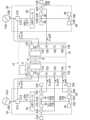
電力計測システム10は、図1及び図2に示すように、電圧入力端子11Aと、電圧計測部12Aと、電流入力端子13Aと、電流計測部14Aと、演算部15Aと、判定部16Aと、を備える。電圧入力端子11Aは、負荷へ電力を供給する給電路C0Aに接続されている。ここで、本実施形態では給電路C0Aを通じて負荷へ供給される電力は交流電力である。電圧計測部12Aは、電圧入力端子11Aに入力される入力電圧V0Aを計測する。ここで、入力電圧V0Aは、給電路C0Aに印加される交流電圧である。電流入力端子13Aには、給電路C0Aに流れる交流電流である入力電流I0Aの電流値に応じた入力信号が入力される。電流計測部14Aは、電流入力端子13Aに入力される入力信号に基づいて入力電流I0Aを計測する。演算部15Aは、入力電圧V0A及び入力電流I0Aの計測結果に基づいて、給電路C0Aを通じて供給される電力の力率F0Aを求める。判定部16Aは、力率F0Aの異常の有無を判定する異常判定を行う。判定部16Aは、異常判定において、力率F0Aが設定力率Fs0以下となった場合に、力率F0Aが異常であると判定する。なお、ここで言う「設定力率Fs0」とは、判定部16Aによる力率F0Aの異常判定の基準となる力率の値である。As shown in FIG. 1 and FIG. 2, the
ここで、電圧入力端子11Aへの配線及び電流入力端子13Aへの配線が正しく施工されている場合に、負荷の動作が正常であれば、演算部15Aによって求められる力率F0Aは所定の正常変動範囲で変化すると想定される。電力計測システム10では、設定力率Fs0を正常変動範囲の下限値よりも低い値に設定しており、判定部16Aは、演算部15Aが求めた力率F0Aを設定力率Fs0と比較することで異常の有無を判定している。演算部15Aが求めた力率が異常と判定された場合は、電圧入力端子11Aへの誤配線及び電流入力端子13Aへの誤配線等の誤施工が発生していると推定できるので、電力計測システム10は、力率F0Aの異常判定の判定結果から誤施工を検出することができる。Here, if the wiring to the
(2)詳細
(2.1)構成
以下に、本実施形態の電力計測システム10の構成について図1及び図2に基づいて説明する。 (2) Details (2.1) Configuration The configuration of a
本実施形態の電力計測システム10は、図1に示すように、電力計測機器である基本ユニット1Aを備える。基本ユニット1Aは、例えば単相3線式の分電盤3Aから給電路C0Aを通じて供給される電力を計測することができる。なお基本ユニット1Aは、三相3線式の分電盤から供給される電力を測定してもよい。As shown in FIG. 1, the
ここで、給電路C0Aは、主幹回路C1Aと、主幹回路C1Aから例えば4個の分岐ブレーカ4Aによって互いに並列に分岐されている分岐回路C2A~C5Aを有する。主幹回路C1Aは、主幹ブレーカ5Aと、電力系統PsAから主幹ブレーカ5Aまでの電路と、を含む。分岐回路C2A~C5Aのそれぞれは、負荷が接続される回路であり、分岐ブレーカ4Aと、主幹ブレーカ5Aから分岐ブレーカ4Aへの電路と、を含む。本実施形態では、一例として、3つの負荷(負荷22A~24A)が、分岐回路C2A~C4Aにそれぞれ接続される場合を想定する。Here, the power supply circuit C0A has a main circuit C1A and branch circuits C2A to C5A that are branched in parallel from the main circuit C1A by, for example, four
電力計測機器である基本ユニット1Aは、電圧入力端子11Aと、電流入力端子13Aと、処理部6Aを有している。処理部6Aは、電圧計測部12Aと、電流計測部14Aと、演算部15Aと、判定部16Aと、を備える。また処理部6Aは、記憶部31Aを更に備える。The
電圧入力端子11Aは、図1に示すように、例えば分電盤3Aの主幹回路C1Aに電気的に接続される。つまり、電圧入力端子11Aには、電力系統PsAから主幹回路C1Aに印加される入力電圧V0Aが入力される。ここで、主幹回路C1Aに印加された入力電圧V0Aは、各分岐ブレーカ4Aを介して分岐回路C2A~分岐回路C5Aのそれぞれに並列に印加される。As shown in FIG. 1, the
電流入力端子13Aは、例えば4つの端子(端子71A~74A)を含む。端子71A~74Aのそれぞれには電流センサが接続可能である。ここで、電流センサは、例えば、変流器(CT: Current Transformer)である。電流センサは、主幹回路C1A及び分岐回路C2A~C5Aに取り付けられ、主幹回路C1A及び分岐回路C2A~C5Aに流れる入力電流I0Aの電流値に応じた入力信号を端子71A~74Aにそれぞれ入力する。本実施形態では、例えば4つの電流センサ(電流センサ81A~84A)が主幹回路C1A及び分岐回路C2A~C4Aにそれぞれ取り付けられる。電流センサ81A~84Aのそれぞれは、端子71A~74Aに接続される。つまり、電流センサ81Aは主幹回路C1Aに流れる入力電流I0A(入力電流I1A)の電流値に応じた入力信号Sig1A)を端子71Aに入力する。また、電流センサ82A~84Aは、分岐回路C2A~C4Aにそれぞれ流れる入力電流I0A(入力電流I2A~I4A)に応じた入力信号Sig2A~Sig4Aを端子72A~74Aにそれぞれ入力する。なお、電流センサ81A~84Aのそれぞれは、主幹回路C1A及び分岐回路C2A~C4Aのそれぞれに非接触の状態で取り付けられる。The
処理部6Aは、例えば、1以上のプロセッサ(マイクロプロセッサ)と1以上のメモリとを含むコンピュータシステムにより実現され得る。つまり、1以上のプロセッサが1以上のメモリに記憶された1以上のプログラム(アプリケーション)を実行することで、処理部6Aとして機能する。プログラムは、ここでは処理部6Aのメモリに予め記録されているが、インターネット等の電気通信回線を通じて、又はメモリカード等の非一時的な記録媒体に記録されて提供されてもよい。The
電圧計測部12Aは、電圧入力端子11Aに入力される入力電圧V0Aを測定する。電圧計測部12Aによる入力電圧V0Aの測定結果は記憶部31Aに記憶される。The
電流計測部14Aは、電流センサ81A~84Aのそれぞれから端子71A~74Aのそれぞれに入力される入力信号Sig1A~Sig4Aに基づいて、端子71A~74Aのそれぞれに対応する主幹回路C1A及び分岐回路C2A~C4Aのそれぞれに流れる入力電流I1A~I4Aを計測する。電流計測部14Aによる入力電流I1A~I4Aの測定結果は記憶部31Aに記憶される。The
演算部15Aは、電圧計測部12Aによる入力電圧V0Aの測定結果及び電流計測部14Aによる入力電流I1Aの測定結果に基づいて、主幹回路C1Aを通じて供給される電力の力率F0A(力率F1A)を求める。また演算部15Aは、入力電圧V0Aの測定結果及び入力電流I2A~I4Aの測定結果に基づいて、分岐回路C2A~C4Aを通じて負荷22A~24Aにそれぞれ供給される電力の力率F0A(力率F2A~F4A)を求める。The
具体的には、演算部15Aは、入力電圧V0A及び入力電流I1A~I4Aの測定結果に基づいて、主幹回路C1Aを通じて供給される有効電力Pe1Aと、負荷22A~24Aでそれぞれ消費される有効電力Pe2A~Pe4Aと、をそれぞれ求める。また演算部15Aは、入力電圧V0Aの実効値及び入力電流I1A~I4Aの実行値に基づいて、主幹回路C1Aを通じて供給される皮相電力Pa1Aと、負荷22A~24Aにそれぞれ供給される皮相電力Pa2A~Pa4Aを求める。演算部15Aは、有効電力Pe1A~Pe4Aの演算結果と、皮相電力Pa1A~Pa4Aの演算結果から、有効電力Pe1A~Pe4Aを皮相電力Pa1A~Pa4Aでそれぞれ除した値である力率F1A~F4Aを求める。演算部15Aによる有効電力Pe1A~Pe4A、皮相電力Pa1A~Pa4A及び力率F1A~F4Aは記憶部31Aに記憶される。Specifically, the
判定部16Aは、演算部15Aが求めた力率F1A~F4Aのそれぞれの異常の有無を判定する異常判定を行う。判定部16Aは、入力電流I1A~I4Aのそれぞれが設定電流値Is0A以上の場合に、力率F1A~F4Aの異常判定を行う。ここで、異常判定とは、力率F1A~F4Aのそれぞれが設定力率Fs0以下となった場合に、力率F1A~F4Aが異常であると判定する処理である。詳細には、判定部16Aは、例えば主幹回路C1A及び分岐回路C2A~C4Aにそれぞれ流れる入力電流I1A~I4Aが設定電流値Is0A以上の場合に、主幹回路C1A及び分岐回路C2A~C4Aのそれぞれを通じて供給される電力のそれぞれの力率F1A~F4Bの異常判定を個別に行う。なお、設定電流値Is0Aは、主幹回路C1A及び分岐回路C2A~C4Aにそれぞれ流れる入力電流I1A~I4Aに対応して個別に設定される。例えば、本実施形態では入力電流I1A~I4Aにそれぞれ対応した複数の設定電流値Is0A(設定電流値Is1A~Is4A)が設定される。この構成により、例えば次のような利点がある。負荷22A~24Aのうち非稼働状態(待機状態)の負荷が存在する場合、対応する分岐回路を通じて非稼働状態の負荷に供給される電力の力率F0Aが、稼働状態の負荷に供給される電力の力率F0Aと比較して小さくなることがある。このとき、非稼働状態の負荷に対応する分岐回路に流れる入力電流I0Aが設定電流値Is0A未満であれば、判定部16Aは非稼働状態の負荷に供給される電力の力率F0Aに対して異常判定を実施しない。これにより、誤施工以外の原因によって設定力率Fs0以下となっている力率F0Aが、判定部16Aによって異常であると判定されることを防ぐことができる。また、設定電流値Is1A~Is4Aが、入力電流I1A~I4Aに対応して個別に設定されることにより、主幹回路C1A及び分岐回路C2A~C4A毎に、異常判定の実施の有無の条件を設定することができる。なお、設定電流値Is1A~Is4Aとして、主幹回路C1Aに接続される主幹ブレーカ5A及び分岐回路C2A~C4Aにそれぞれ接続される分岐ブレーカ4Aのそれぞれの定格電流の値に対して共通の比率Rcを乗して計算される電流値がそれぞれ設定されてもよい。この場合、共通の比率Rcを一つ設定すれば、設定電流値Is1A~Is4Aが自動で計算され、設定される。例えば以下の表1で示すように、主幹回路C1Aに接続される主幹ブレーカ5A及び分岐回路C2A~C4Aにそれぞれ接続される分岐ブレーカ4Aのそれぞれの定格電流の値が、400A、250A、100A及び50Aであり、共通の比率Rcが20%である場合、設定電流値Is1A~Is4Aはそれぞれ80A、50A、20A及び10Aとなる。The

電力計測システム10の処理部6Aは、図2に示すように、設定部30Aを更に備える。設定部30Aは、判定部16Aが、主幹回路C1A及び分岐回路C2A~C4Aのそれぞれについて異常判定を実施するか否かを個別に設定する。処理部6Aは記憶部31Aを更に有し、設定部30Aによる力率F1A~F4Aの異常判定の実施の有無の設定結果は記憶部31Aに記憶される。As shown in FIG. 2, the
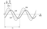
この構成により、判定部16Aに、負荷22A~24Aのうち例えば無効電力制御が行なわれている負荷に供給される電力の力率F0Aに対して、異常判定を実施させないことができる。ここで、無効電力制御が行なわれている負荷には位相差Δθ1が90°である入力電圧V0Aと入力電流I0Aが供給されるため、cosΔθ1で定義される力率F0Aは0となる。なお図3に示すように、周期T1の入力電圧V0Aと入力電流I0Aとの間に無効電力制御によって位相差Δθ1が90°生じている場合には、入力電流I0Aは入力電圧V0Aに対してT1/4だけ遅れていることになる。ここで、無効電力制御が行なわれている負荷に対応する力率F0Aに対して、判定部16Aに異常判定を実施させないことによって、無効電力制御によって値が0になっている力率F0Aが異常であると判定されることを防ぐことができる。This configuration makes it possible to prevent the
なお、処理部6Aが有する電圧計測部12A、電流計測部14A、演算部15A、判定部16A、設定部30A及び記憶部31Aは、実体のある構成を示しているわけではなく、処理部6Aによって実現される機能を示している。The
また電力計測システム10は、図1及び図2に示すように、基本ユニット1Aに接続される表示設定ユニット9を更に備える。表示設定ユニット9は、基本ユニット1Aが備える差込口17に接続される。基本ユニット1Aと、表示設定ユニット9とは、有線通信により通信を行う。なお、基本ユニット1Aと、表示設定ユニット9とは、例えばBluetooth(登録商標)等の電波を媒体とする無線通信によって通信を行ってもよい。The
表示設定ユニット9は、表示部91と、操作部92と、を備える。The
表示部91は、例えば液晶ディスプレイ又は有機EL(Electroluminescence)ディスプレイ等のディスプレイである。表示部91は、情報を表示する。表示部91が表示する情報は、例えば、演算部15Aで求められる、有効電力Pe1A~Pe4A、皮相電力Pa1A~Pa4A及び力率F1A~F4Aの情報等である。また表示部91は、力率F1A~F4Aの異常判定において、力率F1A~F4Aの少なくともいずれかが異常であると判定された場合に、エラー表示を表示する。The
操作部92は、例えば、複数の釦を含む。操作部92は、電力計測システム10のユーザによる操作入力を受け付ける。The
また電力計測システム10は、図1及び図2に示すように、基本ユニット1Aに接続される異種系統ユニット1Bを備える。異種系統ユニット1Bは接続部18を有し、基本ユニット1Aが備える増設用接続部19と、接続部18とが接続される。基本ユニット1Aと、異種系統ユニット1Bとは、例えば有線通信により通信を行う。なお、基本ユニット1Aと、異種系統ユニット1Bとは、例えばBluetooth(登録商標)等の電波を媒体とする無線通信によって通信を行ってもよい。The
異種系統ユニット1Bは電力計測機器であり、例えば三相3線式の分電盤3Bから給電路C0Bを通じて供給される電力を計測することができる。なお異種系統ユニット1Bは、単相3線式の分電盤から供給される電力を測定してもよい。The
ここで、給電路C0Bは、主幹回路C1Bと、主幹回路C1Bから例えば4個の分岐ブレーカ4Bによって互いに並列に分岐されている分岐回路C2B~C5B)を有する。主幹回路C1Bは、主幹ブレーカ5Bと、電力系統PsBから主幹ブレーカ5Bまでの電路と、を含む。分岐回路C2B~C5Bのそれぞれは、負荷が接続される回路であり、分岐ブレーカ4Bと、主幹ブレーカ5Bから分岐ブレーカ4Bへの電路と、を含む。本実施形態では、一例として、1つの負荷(負荷22B)が、分岐回路C2Bに接続される場合を想定する。Here, the power supply circuit C0B has a main circuit C1B and branch circuits C2B to C5B that are branched in parallel from the main circuit C1B by, for example, four
異種系統ユニット1Bは、電圧入力端子11Bと、電流入力端子13Bと、処理部6Bと、を有している。処理部6Bは、電圧計測部12Bと、電流計測部14Bと、演算部15Bと、判定部16Bと、設定部30Bと、記憶部31Bを備える。ここで、異種系統ユニット1Bが備える電圧入力端子11B、電流入力端子13B、電圧計測部12B、電流計測部14B、演算部15B、判定部16B及び設定部30Bのそれぞれは、基本ユニット1Aが備える電圧入力端子11A、電流入力端子13A、電圧計測部12A、電流計測部14A、演算部15A、判定部16A及び設定部30Aのそれぞれと共通する機能を持っている。よって、以下の異種系統ユニット1Bの各部の説明において、基本ユニット1Aの各部と共通する機能については、適宜説明を簡略化する。The
電圧入力端子11Bは、図1に示すように、例えば分電盤3Bの主幹回路C1Bに電気的に接続される。主幹回路C1Bに印加された入力電圧V0Bは、各分岐ブレーカ4Bを介して分岐回路C2B~C5Bのそれぞれに印加される。As shown in FIG. 1, the
電流入力端子13Bは、例えば4つの端子端子71B~74Bを含む。端子71B~74Bのそれぞれには、電流センサを接続可能である。本実施形態では、例えば2つの電流センサ(電流センサ81B及び82B)が主幹回路C1B及びC2Bに取り付けられる。電流センサ81B及び82Bは、それぞれ端子71B及び72Bに接続される。The
電圧計測部12Bは、電圧入力端子11Bに入力される入力電圧V0Bを測定する。電圧計測部12Bによる入力電圧V0Bの測定結果は記憶部31Bに記憶される。The
電流計測部14Bは、電流センサ81B及び82Bから端子71B及び72Bにそれぞれ入力される入力信号Sig1B及びSig2Bに基づいて、主幹回路C1B及び分岐回路C2Bにそれぞれ流れる入力電流I0B(入力電流I1B及びI2B)を計測する。電流計測部14Bによる入力電流I1B及びI2Bの測定結果は記憶部31Bに記憶される。The
演算部15Bは、電圧計測部12Bによる入力電圧V0Bの測定結果及び電流計測部14Bによる入力電流I1Bの測定結果に基づいて、主幹回路C1Bを通じて供給される電力の有効電力Pe1B、皮相電力Pa1B及び力率F1Bを求める。また、演算部15Bは、入力電圧V0Bの測定結果及び入力電流I2Bの測定結果に基づいて、分岐回路C2Bを通じて負荷22Bに供給される電力の有効電力Pe2B、皮相電力Pa2B及び力率F2Bを求める。演算部15Bによる有効電力Pe1B~Pe2B、皮相電力Pa1B~Pa2B及び力率F1B~F2Bは記憶部31Bに記憶される。The
有効電力Pe1B~Pe2B、皮相電力Pa1B~Pa2B及び力率F1B~F2Bの情報は、基本ユニット1Aに接続された表示設定ユニット9の表示部91に表示される。Information on the active powers Pe1B to Pe2B, apparent powers Pa1B to Pa2B, and power factors F1B to F2B is displayed on the
判定部16Bは、演算部15Bが求めた力率F1B~F2Bの異常判定を行う。判定部16Bによる異常判定において力率F1B及び力率F2Bの少なくともいずれか一方が異常であると判定された場合に、表示設定ユニット9の表示部91にエラー表示が表示される。The
(2.2)力率の異常判定の動作例1
本実施形態の電力計測システム10における力率の異常判定の動作例1について、図1~図2、図4、フローチャートである図5、図7~図8に基づいて説明する。 (2.2) Operation example 1 of power factor abnormality determination
An operation example 1 of determining an abnormality in the power factor in the
以下では、図1に示すように異種系統ユニット1Bの端子72Bに接続されるべき電流センサ82Bが、誤施工により図4に示すように基本ユニット1Aの端子72Aに接続された場合について説明する。この場合に、基本ユニット1Aの端子72Aに接続されるべき電流センサ82Aは、異種系統ユニット1Bの端子72Bに接続されていると想定する。またここでは、基本ユニット1Aの動作について説明し、異種系統ユニット1Bの動作については説明を省略する。Below, we will explain the case where the
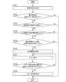
まず、基本ユニット1Aは、電気特性として入力電圧及び入力電流を測定する(ST1)。First, the
詳細には、電圧計測部12Aは、入力電圧V0Aを測定し、電流計測部14Aは、入力端子71A~74Aに入力される信号Sig1A~Sig4Aに基づいて、主幹回路C1Aに流れる入力電流I1A、分岐回路C2Bに流れる入力電流I2B、分岐回路C3Aに流れる入力電流I3A及び分岐回路C4Aに流れる入力電流I4Aを測定する。ここで、電力計測システム10の誤施工により、本来電流計測部14Aが計測する分岐回路C2Aに流れる入力電力I2Aに代わって分岐回路C2Bに流れる入力電流I2Bが計測されている。In detail, the
演算部15Aは、入力電圧V0A、入力電流I1A、入力電流I3A及び入力電流I4Aの測定結果に基づいて、有効電力Pe1A、有効電力Pe3A、有効電力Pe4A、皮相電力Pa1A、皮相電力Pa3A及び皮相電力Pa4Aを求める。また演算部15Aは、入力電圧V0Aと入力電流I2Bとから、有効電力Pe2D及び皮相電力Pa2Dを求める。The
次に演算部15Aは、有効電力Pe1A、有効電力Pe3A、有効電力Pe4A、皮相電力Pa1A、皮相電力Pa3A及び皮相電力Pa4Aから、力率F1A、力率F3A及び力率F4Aを求める。また演算部15Aは、有効電力Pe2Dと皮相電力Pa2Dとから力率F2Dを求める。Then, the
次に判定部16Aは、力率F1A、力率F2D、力率F3A及び力率F4Aの異常判定を行う。以下では、誤施工により、異なる分電盤にそれぞれ対応する入力電圧V0Aと入力電流I2Bとから求められた力率F2Dに対する異常判定について説明する。なお力率F1A、力率F3A及び力率F4Aについても異常判定の流れは共通である。Next, the
判定部16Aは、以下の2つの条件を満たす場合に力率F2Dの異常判定を行う。The
第1の条件は、基本ユニット1Aの測定対象である負荷22Aに供給される電力の力率F2Aが、設定部30Aによって異常判定の実施の対象に設定されているといる条件である。具体的には、第1の条件は、端子72Aに対応する分岐回路C2Aの負荷22Aが、例えば無効電力制御の対象ではないという条件である(ST2:No)。The first condition is that the power factor F2A of the power supplied to the
第2の条件は、入力電流I2Bが、入力電流I2Aに対応して設定された設定電流値Is2A以上であるという条件である(ST3:Yes)。The second condition is that the input current I2B is equal to or greater than the set current value Is2A set corresponding to the input current I2A (ST3: Yes).
判定部16Aは、力率F2D及び入力電流I2Bが、第1の条件及び第2の条件を満たすとき、力率F2Dの異常判定を行う。The
判定部16Aは、設定時間T2以上の間、力率F2Dが設定力率Fs0以下となった場合に(ST4:Yes)、力率F2Dが異常であると判定する(ST5)。If the power factor F2D is equal to or lower than the set power factor Fs0 for a period of time equal to or longer than the set time T2 (ST4: Yes), the
ここで、力率F2Dは入力電圧V0Aと入力電流I2Bとの位相差Δθ2の余弦(cosΔθ2)である。入力電圧V0Aは分電盤3Aに接続される負荷22Aに印加される電圧である。一方、入力電流I2Bは、誤施工によって端子72Aに接続された電流センサ82Bの検出対象の電流であり、分電盤3Bに接続される負荷22Bに供給される電流である。よって位相差Δθ2は、入力電圧V0Aと、電力計測システム10が正しく施工された場合に端子72Aに対応する入力電流I2Aとの位相差Δθ3と比較して大きくなる可能性がある。一例として図7に示すようにΔθ3が10°である場合、入力電流I2Aは、入力電圧V0Aに対してΔθ3/360°・T1=T1/36(T1は入力電流V0A及び入力電流I2Aの周期)だけ遅れる。一方、Δθ2が60°の場合、入力電流I2Bは、入力電圧V0Aに対してΔθ2/360°・T1=T1/6だけ遅れる。すなわち、力率F2Dは、位相差Δθ3の余弦(cosΔθ3)である力率F2Aと比較して小さくなる可能性がある。Here, the power factor F2D is the cosine (cosΔθ2) of the phase difference Δθ2 between the input voltage V0A and the input current I2B. The input voltage V0A is the voltage applied to the
表示設定ユニット9が備える表示部91は、判定部16Aが力率F2Dを異常と判定すると、エラー表示を表示する(ST6)。エラー表示は例えば文字を含む。なお、エラー表示はイラストを含んでもよい。これにより、電力計測システム10のユーザは、電力計測システム10に誤施工(誤配線)が存在する可能性を認識することができる。また、判定部16Aが力率F2Dを異常と判定した場合、表示設定ユニット9はスピーカなどからエラー状態を通知する音声を出力してもよく、電力計測システム10のユーザは音声により電力計測システム10に誤施工(誤配線)が存在する可能性を認識することができる。When the
本実施形態では、表示部91がエラー表示を表示中に、操作部92が電力計測システム10のユーザによるエラー表示の停止操作の操作入力を受け付けると(ST7:Yes)、表示部91がエラー表示を停止する(ST8)。これにより、例えば電力計測システム10における配線を正しく繋ぎ直した後に、エラー表示を停止させることができる。In this embodiment, when the
(2.3)力率の異常判定の動作例2
本実施形態の電力計測システム10における力率の異常判定の動作例2について、図1~図2、フローチャートである図5及び図6、図8に基づいて説明する。ここでは、基本ユニット1Aの動作について説明し、異種系統ユニット1Bの動作については省略する。なお動作例2において、動作例1と共通する部分は適宜説明を簡略化する。 (2.3) Operation example 2 of power factor abnormality judgment
An operation example 2 for determining an abnormality in the power factor in the
動作例2では、電力計測システム10は図1に示すように正しく配線されているとする。In operation example 2, it is assumed that the
まず、基本ユニット1Aは、電気特性である入力電圧V0A、入力電流I1A~I4A及び力率F1A~力率F4Aを測定する(ST1)。First, the
次に判定部16Aは、力率F1A~力率F4Aの異常判定を行う。以下では、一例として、力率F2Aの異常判定について説明する。Then, the
判定部16Aは、力率F2Aが無効電力制御の対象ではなく(ST2:No)、入力電流I2Aが設定電流値Is2A以上であるとき(ST3:Yes)、力率F2Aの異常判断を行う。When the power factor F2A is not subject to reactive power control (ST2: No) and the input current I2A is equal to or greater than the set current value Is2A (ST3: Yes), the
判定部16Aは、設定時間T2以上の間、力率F2Aが設定力率Fs0以下となった場合に(ST4:Yes)、力率F2Aが異常であると判定する(ST5)。これにより、図8に示すように、誤施工以外の原因で、一時的に力率F2Aが設定力率Fs0以下となっており、設定時間T2より短い間に力率F2Aが設定力率Fs0より大きい値に戻る場合は、力率F2Aは異常と判定されない。When the power factor F2A is equal to or lower than the set power factor Fs0 for a period of time equal to or longer than the set time T2 (ST4: Yes), the
表示部91は、判定部16Aが力率F2Aを異常と判定すると、エラー表示を表示する(ST6)。When the
このとき、電力計測システム10のユーザが力率F2Aの値が、運用上の許容範囲であると判断した場合は、表示部91がエラー表示を表示中に、操作部92を操作して(ST7:Yes)、表示部91にエラー表示を停止させることができる(ST8)。At this time, if the user of the
次に、エラー表示の停止後の力率F2Aの異常判定について図6を参照して説明する。Next, we will explain how to determine whether the power factor F2A is abnormal after the error display has stopped, with reference to Figure 6.
基本ユニット1Aは、電気特性を測定する(ST21)。
ここで、判定部16Aは、電力特性である入力電力V0A、入力電流I2A及び力率F2Aが前回のエラー表示が表示されたときと同じ場合(ST22:Yes)、力率F2Aの異常判定を行わない。これにより、前回力率が異常であると判定した時と同じ入力電力V0Aの値及び入力電流I2Aの値のときに、力率F2Aが前回のエラー時に電力計測システム10のユーザが許容した値となった場合に、再度エラー表示が表示部91に表示されることを防ぐ。なお、例えば力率F2Aの値が前回エラー時と同じであっても、入力電力V0Aの値及び入力電流I2Aの値の少なくとも一方が前回エラー時と異なっている場合(ST22:No)は、前回エラー時とは異なった原因で力率F2Aが設定力率Fs0以下となっている可能性があるためST23以降の処理を行うのが好ましい。ここでST23~ST29は、ST2~ST8と同様であるので説明を省略する。Here, when the input power V0A, input current I2A, and power factor F2A, which are the power characteristics, are the same as when the previous error display was displayed (ST22: Yes), the
なお、判定部16Aが、力率F2Aが異常ではないと判定した場合は、基本ユニット1Aは、測定対象の回路(分岐回路C2A)の電気特性の計測を継続する。If the
(3)変形例
以下、上記実施形態の変形例について説明する。ただし上記実施形態と共通する構成要素については同じ参照符号を付して、適宜その説明を省略する。また、以下に説明する変形例の各構成は、上記実施形態で説明した各構成と適宜組み合わせて適用可能である。 (3) Modifications Modifications of the above embodiment will be described below. However, components common to the above embodiment will be given the same reference numerals and their description will be omitted as appropriate. In addition, each configuration of the modification described below can be applied in appropriate combination with each configuration described in the above embodiment.
(3.1)変形例1
本変形例1では、判定部16Aは、記憶部31Aに記憶された有効電力Pe1A~有効電力Pe4Aの計算結果の履歴情報に基づいて、力率F1A~力率F4Aの異常判定の実施の有無を決定する点で上記の実施形態とは異なる。 (3.1) Modification 1
In this modified example 1, the
具体的には、有効電力Pe1A~有効電力Pe4Aのそれぞれの計算結果において、設定電力値以上の値となった履歴情報が存在する場合には、有効電力Pe1A~有効電力Pe4Aのうち設定電力値以上となった有効電力に対応する力率に対して異常判定を実施しない。また、有効電力Pe1A~有効電力Pe4Aのそれぞれの計算結果において、設定電力値以上の値となった履歴情報が存在しない場合には、有効電力Pe1A~有効電力Pe4Aのうち設定電力値以上となっていない有効電力に対応する力率に対して異常判定を実施する。設定電力値は例えば負荷22A~負荷24Aを正常に動作させるために必要な有効電力の最小値に設定される。Specifically, if there is historical information in which the calculation results of each of the active powers Pe1A to Pe4A are equal to or greater than the set power value, then an abnormality determination is not performed for the power factor corresponding to the active power among the active powers Pe1A to Pe4A that is equal to or greater than the set power value. Also, if there is no historical information in which the calculation results of each of the active powers Pe1A to Pe4A are equal to or greater than the set power value, then an abnormality determination is performed for the power factor corresponding to the active power among the active powers Pe1A to Pe4A that is not equal to or greater than the set power value. The set power value is set, for example, to the minimum value of the active power required to operate the
この構成により、設定電力値以上の有効電力が供給された履歴のある負荷に対応する力率は、正常の施工状態で測定されているとみなされる。つまり判定部16Aは、設定電力値以上の有効電力が供給された履歴のある負荷に対応する力率は、誤施工による力率異常が発生しないとして、異常判定を実施しない。一方、設定電力値以上の有効電力が供給された履歴のない負荷に対応する力率は、誤施工により正常に測定されていない可能性があるとみなされ、判定部16Aは、設定電力値以上の有効電力が供給された履歴のない負荷に対応する力率の異常判定を実施する。ここで、設定電力値以上の有効電力が供給された履歴のない状態とは、例えば電力計測システム10の初期施工時であるため、この構成により初期施工時に誤施工を検出できるという利点がある。With this configuration, the power factor corresponding to a load with a history of being supplied with active power equal to or greater than the set power value is considered to have been measured in a normal installation state. In other words, the
なお異種系統ユニット1Bが備える判定部16Bが同様の機能を持っていてもよい。The
(3.2)変形例2
本変形例2では、表示部91が表示するエラー表示が、力率F0Aの異常の原因を示す内容を含む点で上記の実施形態及び変形例1とは異なる。ここで、力率F0Aの異常の原因は、判定部16Aによって推定される。より詳細には、判定部16Aは、力率F0Aの異常判定において例えば力率F4Aが異常であると判定した場合に、0°~180°の範囲で定義される、入力電圧V0Aの位相と入力電流I4Aの位相との位相差Δθ4に基づいて力率F4Aの異常の原因を推定する。 (3.2)
In the present modified example 2, the error display displayed by the
例えば、判定部16Aは、Δθ4=90°の場合は、力率F4Aの異常の原因を、入力電流I4Aが供給される負荷24Aが無効電力制御を実施されているためと判定する。For example, when Δθ4 = 90°, the
判定部16Aは、Δθ4=180°の場合は、入力電圧V0Aと入力電流I4Aの少なくともいずれか一方が極性を誤った状態で測定されているためと判断する。このとき、図9に示すように、入力電流I4Aは入力電圧V0Aに対して、T1/2だけ遅れる。When Δθ4 = 180°, the
判定部16Aは、0°<Δθ4<90°又は90°<Δθ4<180°である場合は、力率F4Aの異常の原因を誤施工(誤配線)と判定する。If 0°<Δθ4<90° or 90°<Δθ4<180°, the
なお、異種系統ユニット1Bが備える判定部16Bが同様の機能を持っていてもよい。The
(3.3)変形例3
本変形例3では、電力計測システム10は、図10に示すように、増設ユニット1Cを備える点で上記の実施形態、変形例1及び変形例2とは異なる。 (3.3) Modification 3
In the present modified example 3, the
増設ユニット1Cは、電流計測機器であり、分電盤3Aの給電路C0Aに流れる電流を計測する。The expansion unit 1C is a current measuring device that measures the current flowing through the power supply circuit C0A of the
増設ユニット1Cは、電流入力端子13Cと、電流計測部14Cと、接続部40と、接続部41と、を備える。The expansion unit 1C includes a
接続部40は基本ユニット1Aの増設用接続部19に接続される。接続部41は異種系統ユニット1Bの接続部18に接続される。The
電流入力端子13Cは、例えば4つの端子(端子71C~端子74C)を含む。端子71C~端子74Cのそれぞれには、電流センサを接続可能である。本変形例3では、図10に示すように例えば5つの電流センサ(電流センサ81A~電流センサ85A)が主幹回路C1A及び分岐回路C2A~分岐回路C5Aにそれぞれ取り付けられる。分岐回路C2A~分岐回路C5Aには、負荷22A~負荷25Aがそれぞれ接続されている。ここで、電流センサ81A~電流センサ84Aは、それぞれ基本ユニット1Aの端子71A~74Aに接続される。電流センサ85Aは、増設ユニット1Cの電流入力端子13Cの端子71Cに接続される。The
電流計測部14Cは、電流センサ85Aから端子71Cに入力される入力信号Sig5Aに基づいて、主幹回路C5Aに流れる入力電流I5Aを計測する。電流計測部14Cによる入力電流I5Aの測定結果は記憶部31Aに記憶される。The
演算部15Aは、入力電圧V0Aの測定結果及び入力電流I5Aの測定結果に基づいて、分岐回路C5Aを通じて負荷25Aに供給される電力の力率F5Aを求める。The
本変形例3では、増設ユニット1Cを備えることで、基本ユニット1Aが、電力を計測可能な回路の数を増やすことができる。In this third variant, by providing an expansion unit 1C, the
(3.4)その他の変形例
以下、実施形態のその他の変形例を列挙する。以下の変形例は、適宜組み合わせて実現されてもよい。 (3.4) Other Modifications Other modifications of the embodiment are listed below. The following modifications may be implemented in appropriate combination.
電力計測システム10と同様の機能は、電力計測方法、コンピュータプログラム、又はプログラムを記録した非一時的な記録媒体等で具現化されてもよい。Functions similar to those of the
上記の実施形態に係る搬送制御方法は、電圧計測処理と、電流計測処理と、演算処理と、判定処理と、を含む。電圧計測処理は、負荷への給電路C0Aに接続される電圧入力端子11Aに入力される入力電圧V0Aを計測する。電流計測処理は、電流入力端子13Aに入力される給電路C0Aに流れる入力電流I0Aの電流値に応じた入力信号に基づいて入力電流I0Aを計測する。演算処理は、入力電圧V0A及び入力電流I0Aの計測結果に基づいて給電路C0Aを通じて供給される電力の力率を求める。判定処理は、力率の異常の有無を判定する異常判定を行う。判定処理は、異常判定において、力率が設定力率Fs0以下となった場合に、力率が異常であると判定する。また、上記実施形態に係る(コンピュータ)プログラムは、コンピュータシステムに、上述の電力計測方法を実行させるためのプログラムである。The transport control method according to the embodiment includes a voltage measurement process, a current measurement process, a calculation process, and a judgment process. The voltage measurement process measures the input voltage V0A input to the
本開示における電力計測システム10は、コンピュータシステムを含んでいる。コンピュータシステムは、ハードウェアとしてのプロセッサ及びメモリを主構成とする。コンピュータシステムのメモリに記録されたプログラムをプロセッサが実行することによって、本開示における電力計測システム10としての機能が実現される。プログラムは、コンピュータシステムのメモリに予め記録されてもよく、電気通信回線を通じて提供されてもよく、コンピュータシステムで読み取り可能なメモリカード、光学ディスク、ハードディスクドライブ等の非一時的記録媒体に記録されて提供されてもよい。コンピュータシステムのプロセッサは、半導体集積回路(IC)又は大規模集積回路(LSI)を含む1ないし複数の電子回路で構成される。ここでいうIC又はLSI等の集積回路は、集積の度合いによって呼び方が異なっており、システムLSI、VLSI(Very Large Scale Integration)、又はULSI(Ultra Large Scale Integration)と呼ばれる集積回路を含む。さらに、LSIの製造後にプログラムされる、FPGA(Field-Programmable GateArray)、又はLSI内部の接合関係の再構成若しくはLSI内部の回路区画の再構成が可能な論理デバイスについても、プロセッサとして採用することができる。複数の電子回路は、1つのチップに集約されていてもよいし、複数のチップに分散して設けられていてもよい。複数のチップは、1つの装置に集約されていてもよいし、複数の装置に分散して設けられていてもよい。ここでいうコンピュータシステムは、1以上のプロセッサ及び1以上のメモリを有するマイクロコントローラを含む。したがって、マイクロコントローラについても、半導体集積回路又は大規模集積回路を含む1ないし複数の電子回路で構成される。The
上記の実施形態では、表示部91が、基本ユニット1Aが有する表示設定ユニット9に備えられているが、基本ユニット1A及び異種系統ユニット1Bが表示部91をそれぞれ備えてもよい。In the above embodiment, the
(4)まとめ
以上述べたように、第1の態様に係る電力計測システム(10)は、電圧入力端子(11A)と、電圧計測部(12A)と、電流入力端子(13A)と、電流計測部(14A)と、演算部(15A)と、判定部(16A)と、を備える。電圧入力端子(11A)は、負荷への給電路(C0A)に接続される。電圧計測部(12A)は、電圧入力端子(11A)に入力される入力電圧(V0A)を計測する。電流入力端子(13A)には、給電路(C0A)に流れる入力電流(I0A)の電流値に応じた入力信号が入力される。電流計測部(14A)は、電流入力端子(13A)に入力される入力信号に基づいて入力電流(I0A)を計測する。演算部(15A)は、入力電圧(V0A)及び入力電流(I0A)の計測結果に基づいて給電路(C0A)を通じて供給される電力の力率(F0A)を求める。判定部(16A)は、力率(F0A)の異常の有無を判定する異常判定を行う。判定部(16A)は、異常判定において、力率(F0A)が設定力率(Fs0)以下となった場合に、力率(F0A)が異常であると判定する。 (4) Summary As described above, the power measurement system (10) according to the first aspect includes a voltage input terminal (11A), a voltage measurement unit (12A), a current input terminal (13A), a current measurement unit (14A), a calculation unit (15A), and a judgment unit (16A). The voltage input terminal (11A) is connected to a power supply path (C0A) to a load. The voltage measurement unit (12A) measures an input voltage (V0A) input to the voltage input terminal (11A). An input signal corresponding to a current value of an input current (I0A) flowing through the power supply path (C0A) is input to the current input terminal (13A). The current measurement unit (14A) measures an input current (I0A) based on an input signal input to the current input terminal (13A). The calculation unit (15A) calculates the power factor (F0A) of the power supplied through the power supply line (C0A) based on the measurement results of the input voltage (V0A) and the input current (I0A). The determination unit (16A) performs an abnormality determination to determine whether or not there is an abnormality in the power factor (F0A). When the power factor (F0A) becomes equal to or lower than a set power factor (Fs0) in the abnormality determination, the determination unit (16A) determines that the power factor (F0A) is abnormal.
この態様によれば、電力の力率(F0A)から電力計測システム(10)の誤施工を検出することができる。According to this embodiment, improper installation of the power measurement system (10) can be detected from the power factor (F0A).
第2の態様に係る電力計測システム(10)では、第1の態様において、演算部(15A)は、入力電圧(V0A)及び入力電流(I0A)の計測結果に基づいて負荷で消費される有効電力を求める。In the power measurement system (10) according to the second aspect, in the first aspect, the calculation unit (15A) calculates the active power consumed by the load based on the measurement results of the input voltage (V0A) and the input current (I0A).
この態様によれば、負荷で消費される有効電力を計測することができる。This aspect makes it possible to measure the active power consumed by the load.
第3の態様に係る電力計測システム(10)では、第2の態様において、判定部(16A)は、有効電力の計算結果の履歴情報に基づいて、有効電力の計算結果が設定電力値以上の値となった履歴情報が存在する場合には異常判定を実施しない。判定部(16A)は、有効電力の計算結果の履歴情報に基づいて、有効電力の計算結果が設定電力値以上の値となった履歴情報が存在しない場合には異常判定を実施する。In the power measurement system (10) according to the third aspect, in the second aspect, the judgment unit (16A) does not perform an abnormality judgment based on the historical information of the calculation results of the active power when historical information exists in which the calculation result of the active power is a value equal to or greater than the set power value. The judgment unit (16A) performs an abnormality judgment based on the historical information of the calculation results of the active power when historical information does not exist in which the calculation result of the active power is a value equal to or greater than the set power value.
この態様によれば、有効電力の計算結果が設定電力値以上の値となった履歴情報が存在しない電力計測システム(10)の初期施工時に誤施工を検出できる。According to this aspect, it is possible to detect erroneous installation during initial installation of a power measurement system (10) that does not have historical information showing that the calculation result of the active power is equal to or greater than the set power value.
第4の態様に係る電力計測システム(10)では、第1~第3のいずれかの態様において、判定部(16A)は、入力電流(I0A)が設定電流値(Is0A)以上の場合に、異常判定を実施する。In the power measurement system (10) according to the fourth aspect, in any of the first to third aspects, the judgment unit (16A) performs an abnormality judgment when the input current (I0A) is equal to or greater than the set current value (Is0A).
この態様によれば、非稼働状態の負荷に供給される電力の力率(F0A)が異常と判定されるのを防ぐことができる。This aspect makes it possible to prevent the power factor (F0A) of the power supplied to a load that is not in operation from being determined to be abnormal.
第5の態様に係る電力計測システム(10)では、第1~第4のいずれかの態様において、給電路(C0A)は、複数の回路を含む。電流入力端子(13A)は、複数の回路にそれぞれ対応した複数の端子を含む。複数の端子のそれぞれには、複数の回路のうち対応する回路に流れる入力電流(I0A)の電流値に応じた入力信号が入力される。電流計測部(14A)は、複数の端子のそれぞれに入力される入力信号に基づいて、複数の回路のうち対応する回路に流れる入力電流(I0A)を計測する。演算部(15A)は、複数の回路のそれぞれを通じて供給される電力の力率(F0A)を求める。判定部(16A)は、複数の回路にそれぞれ流れる入力電流(I0A)が、設定電流値(Is0A)以上の場合に、複数の回路のそれぞれを通じて供給される電力の力率(F0A)の異常判定を個別に行う。設定電流値(Is0A)は、複数の回路にそれぞれ流れる入力電流(I0A)に対応して個別に設定される。In the fifth aspect of the power measurement system (10), in any one of the first to fourth aspects, the power supply path (C0A) includes a plurality of circuits. The current input terminal (13A) includes a plurality of terminals corresponding to the plurality of circuits, respectively. An input signal corresponding to the current value of the input current (I0A) flowing through the corresponding circuit among the plurality of circuits is input to each of the plurality of terminals. The current measurement unit (14A) measures the input current (I0A) flowing through the corresponding circuit among the plurality of circuits based on the input signal input to each of the plurality of terminals. The calculation unit (15A) calculates the power factor (F0A) of the power supplied through each of the plurality of circuits. When the input current (I0A) flowing through each of the plurality of circuits is equal to or greater than the set current value (Is0A), the judgment unit (16A) individually performs an abnormality judgment of the power factor (F0A) of the power supplied through each of the plurality of circuits. The set current value (Is0A) is individually set corresponding to the input current (I0A) flowing through each of the plurality of circuits.
この態様によれば、力率(F0A)の異常判定を行う条件を、複数の回路のそれぞれに対して個別に設定することができる。According to this aspect, the conditions for determining whether the power factor (F0A) is abnormal can be set individually for each of the multiple circuits.
第6の態様に係る電力計測システム(10)では、第1~第5のいずれかの態様において、給電路(C0A)は、複数の回路を含む。電流入力端子(13A)は、複数の回路にそれぞれ対応した複数の端子を含む。複数の端子のそれぞれには、複数の回路のうち対応する回路に流れる入力電流(I0A)の電流値に応じた入力信号が入力される。電流計測部(14A)は、複数の端子のそれぞれに入力される入力信号に基づいて、複数の回路のうち対応する回路に流れる入力電流(I0A)を計測する。演算部(15A)は、複数の回路のそれぞれを通じて供給される電力の力率(F0A)を求める。判定部(16A)は、複数の回路のそれぞれについて異常判定を実施するか否かを個別に設定する設定部(30A)を更に備える。In the power measurement system (10) according to the sixth aspect, in any one of the first to fifth aspects, the power supply path (C0A) includes a plurality of circuits. The current input terminal (13A) includes a plurality of terminals corresponding to the plurality of circuits, respectively. An input signal corresponding to the current value of the input current (I0A) flowing through the corresponding circuit among the plurality of circuits is input to each of the plurality of terminals. The current measurement unit (14A) measures the input current (I0A) flowing through the corresponding circuit among the plurality of circuits based on the input signal input to each of the plurality of terminals. The calculation unit (15A) calculates the power factor (F0A) of the power supplied through each of the plurality of circuits. The judgment unit (16A) further includes a setting unit (30A) that individually sets whether or not to perform an abnormality judgment for each of the plurality of circuits.
この態様によれば、力率(F0A)の異常判定の実施の有無を、複数の回路のそれぞれに対して個別に設定することができる。According to this aspect, whether or not to perform power factor (F0A) abnormality determination can be set individually for each of multiple circuits.
第7の態様に係る電力計測システム(10)では、第1~第6のいずれかの態様において、判定部(16A)は、異常判定において、設定時間(T2)以上の間力率(F0A)が設定力率(Fs0)以下となった場合に、力率(F0A)が異常であると判定する。In the seventh aspect of the power measurement system (10), in any of the first to sixth aspects, the determination unit (16A) determines that the power factor (F0A) is abnormal when the power factor (F0A) is equal to or less than the set power factor (Fs0) for a set time (T2) or more during the abnormality determination.
この態様によれば、一時的な力率(F0A)の低下を、判定部(16A)が異常であると判定することを防ぐことができる。This aspect makes it possible to prevent the judgment unit (16A) from judging a temporary drop in the power factor (F0A) as an abnormality.
第8の態様に係る電力計測システム(10)では、第1~第7のいずれかの態様において、判定部(16A)は、異常判定において力率(F0A)が異常であると判定した場合に、入力電圧(V0A)の位相と入力電流(I0A)の位相との位相差(Δθ1)に基づいて力率(F0A)の異常の原因を推定する。In the power measurement system (10) according to the eighth aspect, in any of the first to seventh aspects, when the determination unit (16A) determines that the power factor (F0A) is abnormal in the abnormality determination, it estimates the cause of the abnormality in the power factor (F0A) based on the phase difference (Δθ1) between the phase of the input voltage (V0A) and the phase of the input current (I0A).
この態様によれば、電力計測システム(10)のユーザが、力率(F0A)の異常の原因を調査することが容易になる。This aspect makes it easier for the user of the power measurement system (10) to investigate the cause of an abnormality in the power factor (F0A).
第9の態様に係る電力計測システム(10)は、第1~第8のいずれかの態様において、表示部(91)と、操作部(92)と、を更に備える。表示部(91)は、異常判定において力率(F0A)が異常であると判定された場合にエラー表示を表示する。操作部(92)は、ユーザによる操作入力を受け付ける。表示部(91)がエラー表示を表示中に、操作部(92)がユーザによるエラー表示の停止操作の操作入力を受け付けると表示部(91)がエラー表示を停止する。The power measurement system (10) according to the ninth aspect is any one of the first to eighth aspects, and further includes a display unit (91) and an operation unit (92). The display unit (91) displays an error display when the power factor (F0A) is determined to be abnormal in the abnormality determination. The operation unit (92) accepts operation input by the user. When the operation unit (92) accepts operation input by the user to stop the error display while the display unit (91) is displaying the error display, the display unit (91) stops the error display.
この態様によれば、ユーザの判断により、表示部(91)にエラー表示を停止させることができる。According to this embodiment, the display unit (91) can stop displaying the error at the user's discretion.
第10の態様に係る電力計測システム(10)では、第9の態様において、判定部(16A)は、エラー表示の停止後に、入力電圧(V0A)、入力電流(I0A)及び力率(F0A)の少なくともいずれか1つが、エラー表示が表示されたときと同じ値である場合には、異常判定を実施しない。In the power measurement system (10) according to the tenth aspect, in the ninth aspect, the judgment unit (16A) does not perform an abnormality judgment if, after the error display has stopped, at least one of the input voltage (V0A), the input current (I0A), and the power factor (F0A) has the same value as when the error display was displayed.
この態様によれば、過去の異常判定において異常があると判断されたが、ユーザによって問題がないと判断された力率(F0A)については、異常判定の対象としないことができる。According to this aspect, a power factor (F0A) that was previously determined to be abnormal but that the user has determined to be fine can be excluded from the abnormality determination.
第11の態様に係る電力計測機器は、第1~第10のいずれかの態様の電力計測システム(10)が備える電力計測機器である。電力計測機器は、電圧入力端子(11A)と、電圧計測部(12A)と、電流入力端子(13A)と、電流計測部(14A)と、演算部(15A)と、判定部(16A)と、を備える。The power measuring device according to the eleventh aspect is a power measuring device provided in the power measuring system (10) according to any one of the first to tenth aspects. The power measuring device includes a voltage input terminal (11A), a voltage measuring unit (12A), a current input terminal (13A), a current measuring unit (14A), a calculation unit (15A), and a determination unit (16A).
この態様によれば、電力の力率(F0A)から電力計測システム(10)の誤施工を検出することができる。According to this embodiment, improper installation of the power measurement system (10) can be detected from the power factor (F0A).
第12の態様に係る電力計測方法は、電圧計測処理と、電流計測処理と、演算処理と、判定処理と、を含む。電圧計測処理は、負荷への給電路(C0A)に接続される電圧入力端子(11A)に入力される入力電圧(V0A)を計測する。電流計測処理は、電流入力端子(13A)に入力される給電路(C0A)に流れる入力電流(I0A)の電流値に応じた入力信号に基づいて入力電流(I0A)を計測する。演算処理は、入力電圧(V0A)及び入力電流(I0A)の計測結果に基づいて給電路(C0A)を通じて供給される電力の力率(F0A)を求める。判定処理は、力率(F0A)の異常の有無を判定する異常判定を行う。判定処理は、異常判定において、力率(F0A)が設定力率(Fs0)以下となった場合に、力率(F0A)が異常であると判定する。The power measurement method according to the twelfth aspect includes a voltage measurement process, a current measurement process, a calculation process, and a judgment process. The voltage measurement process measures an input voltage (V0A) input to a voltage input terminal (11A) connected to a power supply line (C0A) to a load. The current measurement process measures an input current (I0A) based on an input signal corresponding to a current value of the input current (I0A) flowing through the power supply line (C0A) input to a current input terminal (13A). The calculation process finds a power factor (F0A) of the power supplied through the power supply line (C0A) based on the measurement results of the input voltage (V0A) and the input current (I0A). The judgment process performs an abnormality judgment to judge whether or not there is an abnormality in the power factor (F0A). The judgment process judges that the power factor (F0A) is abnormal when the power factor (F0A) is equal to or less than a set power factor (Fs0) in the abnormality judgment.
この態様によれば、電力の力率(F0A)から電力計測システム(10)の誤施工を検出することができる。According to this embodiment, improper installation of the power measurement system (10) can be detected from the power factor (F0A).
第13の態様に係るプログラムは、コンピュータシステムに、第12の態様の電力計測方法を実行させるためのプログラムである。The program according to the thirteenth aspect is a program for causing a computer system to execute the power measurement method according to the twelfth aspect.
この態様によれば、電力の力率(F0A)から電力計測システム(10)の誤施工を検出することができる。According to this embodiment, improper installation of the power measurement system (10) can be detected from the power factor (F0A).
なお、第2~第10の態様は電力計測システム(10)に必須の構成ではなく、適宜省略が可能である。Note that the second to tenth aspects are not essential components of the power measurement system (10) and may be omitted as appropriate.
10 電力計測システム
91 表示部
92 操作部
11A 電圧入力端子
12A 電圧計測部
13A 電流入力端子
14A 電流計測部
15A 演算部
16A 判定部
C0A 給電路
I0A 入力電流
Is0A 設定電流値
F0A 力率
Fs0 設定力率
T2 設定時間
V0A 入力電圧
Δθ1 位相差10
Claims (17)
Translated fromJapanese前記電圧入力端子に入力される入力電圧を計測する電圧計測部と、
前記給電路に流れる入力電流の電流値に応じた入力信号が入力される電流入力端子と、
前記電流入力端子に入力される前記入力信号に基づいて前記入力電流を計測する電流計測部と、
前記入力電圧及び前記入力電流の計測結果に基づいて前記給電路を通じて供給される電力の力率を求める演算部と、
前記力率の異常の有無を判定する異常判定を行う判定部と、を備え、
前記判定部は、前記異常判定において、前記力率が設定力率以下となった場合に、前記力率が異常であると判定し、
前記演算部は、前記入力電圧及び前記入力電流の計測結果に基づいて前記負荷で消費される有効電力を求め、
前記判定部は、前記有効電力の計算結果の履歴情報に基づいて、
前記有効電力の計算結果が設定電力値以上の値となった前記履歴情報が存在する場合には前記異常判定を実施せず、
前記有効電力の計算結果が前記設定電力値以上の値となった前記履歴情報が存在しない場合には前記異常判定を実施する
電力計測システム。 A voltage input terminal connected to a power supply path to a load;
a voltage measurement unit that measures an input voltage input to the voltage input terminal;
a current input terminal to which an input signal corresponding to a current value of an input current flowing through the power supply path is input;
a current measuring unit that measures the input current based on the input signal input to the current input terminal;
a calculation unit that calculates a power factor of the power supplied through the power supply path based on the measurement results of the input voltage and the input current;
a determination unit that performs an abnormality determination to determine whether or not the power factor is abnormal,
The determination unit determines that the power factor is abnormal when the power factor is equal to or lower than a set power factor in the abnormality determination,
The calculation unit calculates an active power consumed by the load based on the measurement results of the input voltage and the input current,
The determination unit, based on history information of the calculation result of the active power,
If there is history information in which the calculation result of the effective power is equal to or greater than a set power value, the abnormality determination is not performed,
When there is no history information in which the calculation result of the effective power is equal to or greater than the set power value, the abnormality determination is performed.
Power measurement system.
前記電圧入力端子に入力される入力電圧を計測する電圧計測部と、a voltage measurement unit that measures an input voltage input to the voltage input terminal;
前記給電路に流れる入力電流の電流値に応じた入力信号が入力される電流入力端子と、a current input terminal to which an input signal corresponding to a current value of an input current flowing through the power supply path is input;
前記電流入力端子に入力される前記入力信号に基づいて前記入力電流を計測する電流計測部と、a current measuring unit that measures the input current based on the input signal input to the current input terminal;
前記入力電圧及び前記入力電流の計測結果に基づいて前記給電路を通じて供給される電力の力率を求める演算部と、a calculation unit that calculates a power factor of the power supplied through the power supply path based on the measurement results of the input voltage and the input current;
前記力率の異常の有無を判定する異常判定を行う判定部と、を備え、a determination unit that performs an abnormality determination to determine whether or not the power factor is abnormal,
前記判定部は、前記異常判定において、前記力率が設定力率以下となった場合に、前記力率が異常であると判定し、The determination unit determines that the power factor is abnormal when the power factor is equal to or lower than a set power factor in the abnormality determination,
前記給電路は、複数の回路を含み、The power supply path includes a plurality of circuits,
前記電流入力端子は、前記複数の回路にそれぞれ対応した複数の端子を含み、the current input terminal includes a plurality of terminals respectively corresponding to the plurality of circuits;
前記複数の端子のそれぞれには、前記複数の回路のうち対応する回路に流れる入力電流の電流値に応じた入力信号が入力され、an input signal corresponding to a current value of an input current flowing through a corresponding one of the plurality of circuits is input to each of the plurality of terminals;
前記電流計測部は、前記複数の端子のそれぞれに入力される前記入力信号に基づいて、前記複数の回路のうち対応する回路に流れる前記入力電流を計測し、the current measurement unit measures the input current flowing through a corresponding circuit among the plurality of circuits based on the input signal input to each of the plurality of terminals;
前記演算部は、前記複数の回路のそれぞれを通じて供給される電力の力率を求め、The calculation unit calculates a power factor of power supplied through each of the plurality of circuits,
前記判定部が前記複数の回路のそれぞれについて前記異常判定を実施するか否かを個別に設定する設定部を更に備えるThe determination unit may further include a setting unit that individually sets whether or not the abnormality determination is to be performed for each of the plurality of circuits.
電力計測システム。Power measurement system.
前記電圧入力端子に入力される入力電圧を計測する電圧計測部と、a voltage measurement unit that measures an input voltage input to the voltage input terminal;
前記給電路に流れる入力電流の電流値に応じた入力信号が入力される電流入力端子と、a current input terminal to which an input signal corresponding to a current value of an input current flowing through the power supply path is input;
前記電流入力端子に入力される前記入力信号に基づいて前記入力電流を計測する電流計測部と、a current measuring unit that measures the input current based on the input signal input to the current input terminal;
前記入力電圧及び前記入力電流の計測結果に基づいて前記給電路を通じて供給される電力の力率を求める演算部と、a calculation unit that calculates a power factor of the power supplied through the power supply path based on the measurement results of the input voltage and the input current;
前記力率の異常の有無を判定する異常判定を行う判定部と、を備え、a determination unit that performs an abnormality determination to determine whether or not the power factor is abnormal,
前記判定部は、前記異常判定において、前記力率が設定力率以下となった場合に、前記力率が異常であると判定し、The determination unit determines that the power factor is abnormal when the power factor is equal to or lower than a set power factor in the abnormality determination,
前記判定部は、前記異常判定において、設定時間以上の間前記力率が前記設定力率以下となった場合に、前記力率が異常であると判定するThe determination unit determines that the power factor is abnormal when the power factor is equal to or lower than the set power factor for a set time or longer in the abnormality determination.
電力計測システム。Power measurement system.
請求項2又は3に記載の電力計測システム。The power measurement system according to claim 2 or 3.
前記有効電力の計算結果が設定電力値以上の値となった前記履歴情報が存在する場合には前記異常判定を実施せず、If there is history information in which the calculation result of the effective power is equal to or greater than a set power value, the abnormality determination is not performed,
前記有効電力の計算結果が前記設定電力値以上の値となった前記履歴情報が存在しない場合には前記異常判定を実施するWhen there is no history information in which the calculation result of the effective power is equal to or greater than the set power value, the abnormality determination is performed.
請求項4に記載の電力計測システム。The power measurement system according to claim 4 .
請求項1~5のいずれか1項に記載の電力計測システム。The power measurement system according to any one of claims 1 to 5.
前記電流入力端子は、前記複数の回路にそれぞれ対応した複数の端子を含み、the current input terminal includes a plurality of terminals respectively corresponding to the plurality of circuits;
前記複数の端子のそれぞれには、前記複数の回路のうち対応する回路に流れる入力電流の電流値に応じた入力信号が入力され、an input signal corresponding to a current value of an input current flowing through a corresponding one of the plurality of circuits is input to each of the plurality of terminals;
前記電流計測部は、前記複数の端子のそれぞれに入力される前記入力信号に基づいて、前記複数の回路のうち対応する回路に流れる前記入力電流を計測し、the current measurement unit measures the input current flowing through a corresponding circuit among the plurality of circuits based on the input signal input to each of the plurality of terminals;
前記演算部は、前記複数の回路のそれぞれを通じて供給される電力の力率を求め、The calculation unit calculates a power factor of power supplied through each of the plurality of circuits,
前記判定部は、前記複数の回路にそれぞれ流れる前記入力電流が、前記複数の回路にそれぞれ流れる前記入力電流に対応して個別に設定される設定電流値以上の場合に、前記複数の回路のそれぞれを通じて供給される電力の力率の前記異常判定を個別に行うThe determination unit performs the abnormality determination individually on the power factor of the power supplied through each of the plurality of circuits when the input current flowing through each of the plurality of circuits is equal to or greater than a set current value that is individually set corresponding to the input current flowing through each of the plurality of circuits.
請求項1~6のいずれか1項に記載の電力計測システム。The power measurement system according to any one of claims 1 to 6.
前記電流入力端子は、前記複数の回路にそれぞれ対応した複数の端子を含み、the current input terminal includes a plurality of terminals respectively corresponding to the plurality of circuits;
前記複数の端子のそれぞれには、前記複数の回路のうち対応する回路に流れる入力電流の電流値に応じた入力信号が入力され、an input signal corresponding to a current value of an input current flowing through a corresponding one of the plurality of circuits is input to each of the plurality of terminals;
前記電流計測部は、前記複数の端子のそれぞれに入力される前記入力信号に基づいて、前記複数の回路のうち対応する回路に流れる前記入力電流を計測し、the current measurement unit measures the input current flowing through a corresponding circuit among the plurality of circuits based on the input signal input to each of the plurality of terminals;
前記演算部は、前記複数の回路のそれぞれを通じて供給される電力の力率を求め、The calculation unit calculates a power factor of power supplied through each of the plurality of circuits,
前記判定部が前記複数の回路のそれぞれについて前記異常判定を実施するか否かを個別に設定する設定部を更に備えるThe determination unit may further include a setting unit that individually sets whether or not the abnormality determination is to be performed for each of the plurality of circuits.
請求項1又は3に記載の電力計測システム。The power measurement system according to claim 1 .
請求項1又は2に記載の電力計測システム。3. The power measurement system according to claim 1 or 2.
請求項1~9のいずれか1項に記載の電力計測システム。The power measurement system according to any one of claims 1 to 9.
ユーザによる操作入力を受け付ける操作部と、を更に備え、An operation unit that accepts an operation input by a user,
前記表示部が前記エラー表示を表示中に、前記操作部が前記ユーザによる前記エラー表示の停止操作の操作入力を受け付けると前記表示部が前記エラー表示を停止するWhen the operation unit receives an operation input from the user for stopping the error display while the display unit is displaying the error display, the display unit stops the error display.
請求項1~10のいずれか1項に記載の電力計測システム。The power measurement system according to any one of claims 1 to 10.
請求項11に記載の電力計測システム。The power measurement system of claim 11.
前記電圧入力端子と、前記電圧計測部と、前記電流入力端子と、前記電流計測部と、前記演算部と、前記判定部と、を備えるThe voltage input terminal, the voltage measurement unit, the current input terminal, the current measurement unit, the calculation unit, and the determination unit.
電力計測機器。Power measuring equipment.
電流入力端子に入力される前記給電路に流れる入力電流の電流値に応じた入力信号に基づいて前記入力電流を計測する電流計測処理と、a current measurement process for measuring an input current based on an input signal corresponding to a current value of the input current flowing through the power supply path and input to a current input terminal;
前記入力電圧及び前記入力電流の計測結果に基づいて前記給電路を通じて供給される電力の力率を求める演算処理と、A calculation process for calculating a power factor of the power supplied through the power supply path based on the measurement results of the input voltage and the input current;
前記力率の異常の有無を判定する異常判定を行う判定処理と、を含み、A determination process for performing an abnormality determination for determining whether or not the power factor is abnormal,
前記判定処理は、前記異常判定において、前記力率が設定力率以下となった場合に、前記力率が異常であると判定し、The determination process determines that the power factor is abnormal when the power factor is equal to or lower than a set power factor in the abnormality determination,
前記演算処理では、前記入力電圧及び前記入力電流の計測結果に基づいて前記負荷で消費される有効電力を求め、The calculation process calculates an active power consumed by the load based on the measurement results of the input voltage and the input current;
前記判定処理では、前記有効電力の計算結果の履歴情報に基づいて、In the determination process, based on history information of the calculation results of the active power,
前記有効電力の計算結果が設定電力値以上の値となった前記履歴情報が存在する場合には前記異常判定を実施せず、If there is history information in which the calculation result of the effective power is equal to or greater than a set power value, the abnormality determination is not performed,
前記有効電力の計算結果が前記設定電力値以上の値となった前記履歴情報が存在しない場合には前記異常判定を実施するWhen there is no history information in which the calculation result of the effective power is equal to or greater than the set power value, the abnormality determination is performed.
電力計測方法。Power measurement methods.
電流入力端子に入力される前記給電路に流れる入力電流の電流値に応じた入力信号に基づいて前記入力電流を計測する電流計測処理と、a current measurement process for measuring an input current based on an input signal corresponding to a current value of the input current flowing through the power supply path and input to a current input terminal;
前記入力電圧及び前記入力電流の計測結果に基づいて前記給電路を通じて供給される電力の力率を求める演算処理と、A calculation process for calculating a power factor of the power supplied through the power supply path based on the measurement results of the input voltage and the input current;
前記力率の異常の有無を判定する異常判定を行う判定処理と、を含み、A determination process for performing an abnormality determination for determining whether or not the power factor is abnormal,
前記判定処理は、前記異常判定において、前記力率が設定力率以下となった場合に、前記力率が異常であると判定し、The determination process determines that the power factor is abnormal when the power factor is equal to or lower than a set power factor in the abnormality determination,
前記給電路は、複数の回路を含み、The power supply path includes a plurality of circuits,
前記電流入力端子は、前記複数の回路にそれぞれ対応した複数の端子を含み、the current input terminal includes a plurality of terminals respectively corresponding to the plurality of circuits;
前記複数の端子のそれぞれには、前記複数の回路のうち対応する回路に流れる入力電流の電流値に応じた入力信号が入力され、an input signal corresponding to a current value of an input current flowing through a corresponding one of the plurality of circuits is input to each of the plurality of terminals;
前記電流計測処理では、前記複数の端子のそれぞれに入力される前記入力信号に基づいて、前記複数の回路のうち対応する回路に流れる前記入力電流を計測し、the current measurement process measures the input current flowing through a corresponding circuit among the plurality of circuits based on the input signal input to each of the plurality of terminals;
前記演算処理では、前記複数の回路のそれぞれを通じて供給される電力の力率を求め、The calculation process includes calculating a power factor of the power supplied through each of the plurality of circuits;
前記判定処理において前記複数の回路のそれぞれについて前記異常判定を実施するか否かを個別に設定する設定処理を更に含むThe method further includes a setting process for individually setting whether or not the abnormality determination is to be performed for each of the plurality of circuits in the determination process.
電力計測方法。Power measurement methods.
電流入力端子に入力される前記給電路に流れる入力電流の電流値に応じた入力信号に基づいて前記入力電流を計測する電流計測処理と、a current measurement process for measuring an input current based on an input signal corresponding to a current value of the input current flowing through the power supply path and input to a current input terminal;
前記入力電圧及び前記入力電流の計測結果に基づいて前記給電路を通じて供給される電力の力率を求める演算処理と、A calculation process for calculating a power factor of the power supplied through the power supply path based on the measurement results of the input voltage and the input current;
前記力率の異常の有無を判定する異常判定を行う判定処理と、を含み、A determination process for performing an abnormality determination for determining whether or not the power factor is abnormal,
前記判定処理は、前記異常判定において、前記力率が設定力率以下となった場合に、前記力率が異常であると判定し、The determination process determines that the power factor is abnormal when the power factor is equal to or lower than a set power factor in the abnormality determination,
前記判定処理では、前記異常判定において、設定時間以上の間前記力率が前記設定力率以下となった場合に、前記力率が異常であると判定するIn the determination process, when the power factor is equal to or lower than the set power factor for a set time or longer in the abnormality determination, the power factor is determined to be abnormal.
電力計測方法。Power measurement methods.
プログラム。Program.
Priority Applications (1)
| Application Number | Priority Date | Filing Date | Title |
|---|---|---|---|
| JP2021097579AJP7633886B2 (en) | 2021-06-10 | 2021-06-10 | Power measurement system, power measurement device, power measurement method and program |
Applications Claiming Priority (1)
| Application Number | Priority Date | Filing Date | Title |
|---|---|---|---|
| JP2021097579AJP7633886B2 (en) | 2021-06-10 | 2021-06-10 | Power measurement system, power measurement device, power measurement method and program |
Publications (2)
| Publication Number | Publication Date |
|---|---|
| JP2022189164A JP2022189164A (en) | 2022-12-22 |
| JP7633886B2true JP7633886B2 (en) | 2025-02-20 |
Family
ID=84533289
Family Applications (1)
| Application Number | Title | Priority Date | Filing Date |
|---|---|---|---|
| JP2021097579AActiveJP7633886B2 (en) | 2021-06-10 | 2021-06-10 | Power measurement system, power measurement device, power measurement method and program |
Country Status (1)
| Country | Link |
|---|---|
| JP (1) | JP7633886B2 (en) |
Citations (3)
| Publication number | Priority date | Publication date | Assignee | Title |
|---|---|---|---|---|
| JP2001124806A (en) | 1999-10-27 | 2001-05-11 | Mitsubishi Electric Corp | Three-phase power meter, three-phase watt-hour meter, and method of determining connection state thereof |
| JP2002286769A (en) | 2001-03-23 | 2002-10-03 | Mitsubishi Electric Corp | Power meter |
| US20210068023A1 (en) | 2003-08-25 | 2021-03-04 | Signal Trust For Wireless Innovation | Method and apparatus for transmitting data via a plurality of cells |
Family Cites Families (5)
| Publication number | Priority date | Publication date | Assignee | Title |
|---|---|---|---|---|
| JPH08172719A (en)* | 1994-12-19 | 1996-07-02 | Sumitomo Electric Ind Ltd | Transmission line accident detection method |
| JPH09229981A (en)* | 1996-02-21 | 1997-09-05 | Hitachi Ltd | Monitoring device and harmonic monitoring system used for monitoring harmonics |
| JPH1014135A (en)* | 1996-06-28 | 1998-01-16 | Hitachi Ltd | Monitoring device |
| JP4915788B2 (en)* | 2006-10-02 | 2012-04-11 | パナソニック株式会社 | Power monitoring system |
| JP7411927B2 (en)* | 2019-11-14 | 2024-01-12 | パナソニックIpマネジメント株式会社 | Judgment system, judgment method and program |
- 2021
- 2021-06-10JPJP2021097579Apatent/JP7633886B2/enactiveActive
Patent Citations (3)
| Publication number | Priority date | Publication date | Assignee | Title |
|---|---|---|---|---|
| JP2001124806A (en) | 1999-10-27 | 2001-05-11 | Mitsubishi Electric Corp | Three-phase power meter, three-phase watt-hour meter, and method of determining connection state thereof |
| JP2002286769A (en) | 2001-03-23 | 2002-10-03 | Mitsubishi Electric Corp | Power meter |
| US20210068023A1 (en) | 2003-08-25 | 2021-03-04 | Signal Trust For Wireless Innovation | Method and apparatus for transmitting data via a plurality of cells |
Also Published As
| Publication number | Publication date |
|---|---|
| JP2022189164A (en) | 2022-12-22 |
Similar Documents
| Publication | Publication Date | Title |
|---|---|---|
| US9194884B1 (en) | Integrated circuit with analog device fault detection | |
| US8060321B2 (en) | System and method for detecting an electrical short across a static switch of an uninterruptible power supply | |
| CN107431441B (en) | Method for detecting a faulty rectifier or rectifier source in a UPS | |
| EP2380253A1 (en) | A sentinel unit for an it electrical distribution system having a floating reference conductor | |
| JP7633886B2 (en) | Power measurement system, power measurement device, power measurement method and program | |
| US8058751B2 (en) | Circuit interrupter and method of processor phase synchronization | |
| JP6406896B2 (en) | Device management system, power measuring device, and device management method | |
| JP2010249802A (en) | External terminal open / short circuit inspection method in integrated circuit and external terminal open / short circuit inspection apparatus in integrated circuit | |
| US11823962B2 (en) | Back end of line (BEOL) process corner sensing | |
| US9048656B2 (en) | Circuit interrupter including supervisory function for protective function and hardware circuit repetitive test function | |
| JP7411927B2 (en) | Judgment system, judgment method and program | |
| JP6830220B2 (en) | Abnormality judgment method, abnormality judgment system, program, cutoff system, and distribution board | |
| US10530182B2 (en) | UPS power failure detection | |
| JP5326898B2 (en) | External terminal open / short circuit inspection method in integrated circuit and external terminal open / short circuit inspection apparatus in integrated circuit | |
| JP2020193916A (en) | Monitoring system, method for monitoring, program, and distribution board | |
| JP6671031B2 (en) | Abnormality determination method, abnormality determination system, program, shut-off system, and distribution board | |
| US6417701B1 (en) | Method and apparatus for identifying a waveform period | |
| JP7629357B2 (en) | Power measurement system, power measurement device, power measurement method, and program | |
| JP7705338B2 (en) | Power measurement system and distribution board | |
| JP4690680B2 (en) | Electricity meter | |
| CN120105995B (en) | Data processing method, device, power supply circuit, chip, semiconductor component, electronic apparatus, and storage medium | |
| CN115629287B (en) | Method for measuring edge minority carrier concentration and reverse bias leakage and related equipment | |
| JP2010252563A (en) | Inverter protection method and protection device | |
| JP2006010435A (en) | Voltage abnormality detector | |
| JP2023021822A (en) | Determination device, determination method, and program |
Legal Events
| Date | Code | Title | Description |
|---|---|---|---|
| A621 | Written request for application examination | Free format text:JAPANESE INTERMEDIATE CODE: A621 Effective date:20240221 | |
| A977 | Report on retrieval | Free format text:JAPANESE INTERMEDIATE CODE: A971007 Effective date:20241004 | |
| A131 | Notification of reasons for refusal | Free format text:JAPANESE INTERMEDIATE CODE: A131 Effective date:20241022 | |
| A521 | Request for written amendment filed | Free format text:JAPANESE INTERMEDIATE CODE: A523 Effective date:20241223 | |
| TRDD | Decision of grant or rejection written | ||
| A01 | Written decision to grant a patent or to grant a registration (utility model) | Free format text:JAPANESE INTERMEDIATE CODE: A01 Effective date:20250114 | |
| A61 | First payment of annual fees (during grant procedure) | Free format text:JAPANESE INTERMEDIATE CODE: A61 Effective date:20250207 | |
| R150 | Certificate of patent or registration of utility model | Ref document number:7633886 Country of ref document:JP Free format text:JAPANESE INTERMEDIATE CODE: R150 |