JP7633808B2 - Device for use with a surgically created orifice - Patent application - Google Patents
Device for use with a surgically created orifice - Patent applicationDownload PDFInfo
- Publication number
- JP7633808B2 JP7633808B2JP2020547099AJP2020547099AJP7633808B2JP 7633808 B2JP7633808 B2JP 7633808B2JP 2020547099 AJP2020547099 AJP 2020547099AJP 2020547099 AJP2020547099 AJP 2020547099AJP 7633808 B2JP7633808 B2JP 7633808B2
- Authority
- JP
- Japan
- Prior art keywords
- connection device
- shell
- tubular member
- orifice
- surgically created
- Prior art date
- Legal status (The legal status is an assumption and is not a legal conclusion. Google has not performed a legal analysis and makes no representation as to the accuracy of the status listed.)
- Active
Links
Images


Classifications
- A—HUMAN NECESSITIES
- A61—MEDICAL OR VETERINARY SCIENCE; HYGIENE
- A61F—FILTERS IMPLANTABLE INTO BLOOD VESSELS; PROSTHESES; DEVICES PROVIDING PATENCY TO, OR PREVENTING COLLAPSING OF, TUBULAR STRUCTURES OF THE BODY, e.g. STENTS; ORTHOPAEDIC, NURSING OR CONTRACEPTIVE DEVICES; FOMENTATION; TREATMENT OR PROTECTION OF EYES OR EARS; BANDAGES, DRESSINGS OR ABSORBENT PADS; FIRST-AID KITS
- A61F5/00—Orthopaedic methods or devices for non-surgical treatment of bones or joints; Nursing devices ; Anti-rape devices
- A61F5/44—Devices worn by the patient for reception of urine, faeces, catamenial or other discharge; Colostomy devices
- A61F5/4401—Devices worn by the patient for reception of urine, faeces, catamenial or other discharge; Colostomy devices with absorbent pads
- A—HUMAN NECESSITIES
- A61—MEDICAL OR VETERINARY SCIENCE; HYGIENE
- A61F—FILTERS IMPLANTABLE INTO BLOOD VESSELS; PROSTHESES; DEVICES PROVIDING PATENCY TO, OR PREVENTING COLLAPSING OF, TUBULAR STRUCTURES OF THE BODY, e.g. STENTS; ORTHOPAEDIC, NURSING OR CONTRACEPTIVE DEVICES; FOMENTATION; TREATMENT OR PROTECTION OF EYES OR EARS; BANDAGES, DRESSINGS OR ABSORBENT PADS; FIRST-AID KITS
- A61F5/00—Orthopaedic methods or devices for non-surgical treatment of bones or joints; Nursing devices ; Anti-rape devices
- A61F5/44—Devices worn by the patient for reception of urine, faeces, catamenial or other discharge; Colostomy devices
- A61F5/4404—Details or parts
- A61F5/4405—Valves or valve arrangements specially adapted therefor ; Fluid inlets or outlets
- A—HUMAN NECESSITIES
- A61—MEDICAL OR VETERINARY SCIENCE; HYGIENE
- A61F—FILTERS IMPLANTABLE INTO BLOOD VESSELS; PROSTHESES; DEVICES PROVIDING PATENCY TO, OR PREVENTING COLLAPSING OF, TUBULAR STRUCTURES OF THE BODY, e.g. STENTS; ORTHOPAEDIC, NURSING OR CONTRACEPTIVE DEVICES; FOMENTATION; TREATMENT OR PROTECTION OF EYES OR EARS; BANDAGES, DRESSINGS OR ABSORBENT PADS; FIRST-AID KITS
- A61F5/00—Orthopaedic methods or devices for non-surgical treatment of bones or joints; Nursing devices ; Anti-rape devices
- A61F5/44—Devices worn by the patient for reception of urine, faeces, catamenial or other discharge; Colostomy devices
- A61F5/4404—Details or parts
- A61F5/4407—Closure means other than valves
- A—HUMAN NECESSITIES
- A61—MEDICAL OR VETERINARY SCIENCE; HYGIENE
- A61F—FILTERS IMPLANTABLE INTO BLOOD VESSELS; PROSTHESES; DEVICES PROVIDING PATENCY TO, OR PREVENTING COLLAPSING OF, TUBULAR STRUCTURES OF THE BODY, e.g. STENTS; ORTHOPAEDIC, NURSING OR CONTRACEPTIVE DEVICES; FOMENTATION; TREATMENT OR PROTECTION OF EYES OR EARS; BANDAGES, DRESSINGS OR ABSORBENT PADS; FIRST-AID KITS
- A61F5/00—Orthopaedic methods or devices for non-surgical treatment of bones or joints; Nursing devices ; Anti-rape devices
- A61F5/44—Devices worn by the patient for reception of urine, faeces, catamenial or other discharge; Colostomy devices
- A61F5/443—Devices worn by the patient for reception of urine, faeces, catamenial or other discharge; Colostomy devices having adhesive seals for securing to the body, e.g. of hydrocolloid type seals, e.g. gels, starches, karaya gums
- A—HUMAN NECESSITIES
- A61—MEDICAL OR VETERINARY SCIENCE; HYGIENE
- A61F—FILTERS IMPLANTABLE INTO BLOOD VESSELS; PROSTHESES; DEVICES PROVIDING PATENCY TO, OR PREVENTING COLLAPSING OF, TUBULAR STRUCTURES OF THE BODY, e.g. STENTS; ORTHOPAEDIC, NURSING OR CONTRACEPTIVE DEVICES; FOMENTATION; TREATMENT OR PROTECTION OF EYES OR EARS; BANDAGES, DRESSINGS OR ABSORBENT PADS; FIRST-AID KITS
- A61F5/00—Orthopaedic methods or devices for non-surgical treatment of bones or joints; Nursing devices ; Anti-rape devices
- A61F5/44—Devices worn by the patient for reception of urine, faeces, catamenial or other discharge; Colostomy devices
- A61F5/445—Colostomy, ileostomy or urethrostomy devices
- A61F5/448—Means for attaching bag to seal ring
- A—HUMAN NECESSITIES
- A61—MEDICAL OR VETERINARY SCIENCE; HYGIENE
- A61M—DEVICES FOR INTRODUCING MEDIA INTO, OR ONTO, THE BODY; DEVICES FOR TRANSDUCING BODY MEDIA OR FOR TAKING MEDIA FROM THE BODY; DEVICES FOR PRODUCING OR ENDING SLEEP OR STUPOR
- A61M39/00—Tubes, tube connectors, tube couplings, valves, access sites or the like, specially adapted for medical use
- A61M39/02—Access sites
- A61M39/0247—Semi-permanent or permanent transcutaneous or percutaneous access sites to the inside of the body
- A—HUMAN NECESSITIES
- A61—MEDICAL OR VETERINARY SCIENCE; HYGIENE
- A61F—FILTERS IMPLANTABLE INTO BLOOD VESSELS; PROSTHESES; DEVICES PROVIDING PATENCY TO, OR PREVENTING COLLAPSING OF, TUBULAR STRUCTURES OF THE BODY, e.g. STENTS; ORTHOPAEDIC, NURSING OR CONTRACEPTIVE DEVICES; FOMENTATION; TREATMENT OR PROTECTION OF EYES OR EARS; BANDAGES, DRESSINGS OR ABSORBENT PADS; FIRST-AID KITS
- A61F5/00—Orthopaedic methods or devices for non-surgical treatment of bones or joints; Nursing devices ; Anti-rape devices
- A61F5/44—Devices worn by the patient for reception of urine, faeces, catamenial or other discharge; Colostomy devices
- A61F5/445—Colostomy, ileostomy or urethrostomy devices
- A61F2005/4455—Implantable
- A—HUMAN NECESSITIES
- A61—MEDICAL OR VETERINARY SCIENCE; HYGIENE
- A61F—FILTERS IMPLANTABLE INTO BLOOD VESSELS; PROSTHESES; DEVICES PROVIDING PATENCY TO, OR PREVENTING COLLAPSING OF, TUBULAR STRUCTURES OF THE BODY, e.g. STENTS; ORTHOPAEDIC, NURSING OR CONTRACEPTIVE DEVICES; FOMENTATION; TREATMENT OR PROTECTION OF EYES OR EARS; BANDAGES, DRESSINGS OR ABSORBENT PADS; FIRST-AID KITS
- A61F5/00—Orthopaedic methods or devices for non-surgical treatment of bones or joints; Nursing devices ; Anti-rape devices
- A61F5/44—Devices worn by the patient for reception of urine, faeces, catamenial or other discharge; Colostomy devices
- A61F5/445—Colostomy, ileostomy or urethrostomy devices
- A61F5/449—Body securing means, e.g. belts, garments
- A—HUMAN NECESSITIES
- A61—MEDICAL OR VETERINARY SCIENCE; HYGIENE
- A61M—DEVICES FOR INTRODUCING MEDIA INTO, OR ONTO, THE BODY; DEVICES FOR TRANSDUCING BODY MEDIA OR FOR TAKING MEDIA FROM THE BODY; DEVICES FOR PRODUCING OR ENDING SLEEP OR STUPOR
- A61M39/00—Tubes, tube connectors, tube couplings, valves, access sites or the like, specially adapted for medical use
- A61M39/02—Access sites
- A61M39/0247—Semi-permanent or permanent transcutaneous or percutaneous access sites to the inside of the body
- A61M2039/0264—Semi-permanent or permanent transcutaneous or percutaneous access sites to the inside of the body with multiple inlets or multiple outlets
- A—HUMAN NECESSITIES
- A61—MEDICAL OR VETERINARY SCIENCE; HYGIENE
- A61M—DEVICES FOR INTRODUCING MEDIA INTO, OR ONTO, THE BODY; DEVICES FOR TRANSDUCING BODY MEDIA OR FOR TAKING MEDIA FROM THE BODY; DEVICES FOR PRODUCING OR ENDING SLEEP OR STUPOR
- A61M39/00—Tubes, tube connectors, tube couplings, valves, access sites or the like, specially adapted for medical use
- A61M39/02—Access sites
- A61M39/0247—Semi-permanent or permanent transcutaneous or percutaneous access sites to the inside of the body
- A61M2039/0276—Semi-permanent or permanent transcutaneous or percutaneous access sites to the inside of the body for introducing or removing fluids into or out of the body
- A—HUMAN NECESSITIES
- A61—MEDICAL OR VETERINARY SCIENCE; HYGIENE
- A61M—DEVICES FOR INTRODUCING MEDIA INTO, OR ONTO, THE BODY; DEVICES FOR TRANSDUCING BODY MEDIA OR FOR TAKING MEDIA FROM THE BODY; DEVICES FOR PRODUCING OR ENDING SLEEP OR STUPOR
- A61M39/00—Tubes, tube connectors, tube couplings, valves, access sites or the like, specially adapted for medical use
- A61M39/02—Access sites
- A61M39/0247—Semi-permanent or permanent transcutaneous or percutaneous access sites to the inside of the body
- A61M2039/0282—Semi-permanent or permanent transcutaneous or percutaneous access sites to the inside of the body with implanted tubes connected to the port
- A—HUMAN NECESSITIES
- A61—MEDICAL OR VETERINARY SCIENCE; HYGIENE
- A61M—DEVICES FOR INTRODUCING MEDIA INTO, OR ONTO, THE BODY; DEVICES FOR TRANSDUCING BODY MEDIA OR FOR TAKING MEDIA FROM THE BODY; DEVICES FOR PRODUCING OR ENDING SLEEP OR STUPOR
- A61M39/00—Tubes, tube connectors, tube couplings, valves, access sites or the like, specially adapted for medical use
- A61M39/02—Access sites
- A61M39/0247—Semi-permanent or permanent transcutaneous or percutaneous access sites to the inside of the body
- A61M2039/0288—Semi-permanent or permanent transcutaneous or percutaneous access sites to the inside of the body protectors, caps or covers therefor
Landscapes
- Health & Medical Sciences (AREA)
- Heart & Thoracic Surgery (AREA)
- Life Sciences & Earth Sciences (AREA)
- General Health & Medical Sciences (AREA)
- Animal Behavior & Ethology (AREA)
- Veterinary Medicine (AREA)
- Engineering & Computer Science (AREA)
- Biomedical Technology (AREA)
- Public Health (AREA)
- Vascular Medicine (AREA)
- Epidemiology (AREA)
- Nursing (AREA)
- Orthopedic Medicine & Surgery (AREA)
- Hematology (AREA)
- Pulmonology (AREA)
- Anesthesiology (AREA)
- Biophysics (AREA)
- Gastroenterology & Hepatology (AREA)
- Chemical & Material Sciences (AREA)
- Dispersion Chemistry (AREA)
- Orthopedics, Nursing, And Contraception (AREA)
- Prostheses (AREA)
- Infusion, Injection, And Reservoir Apparatuses (AREA)
- Surgical Instruments (AREA)
Description
Translated fromJapanese本発明は、外科的に作成されたオリフィスと共に使用するのに適した装置に関する。より詳細には、本発明は、排他的ではないが、外科的に作成された胃腸管の造瘻またはストーマを接続する際に使用する装置に関する。The present invention relates to devices suitable for use with surgically created orifices. More particularly, but not exclusively, the present invention relates to devices for use in connecting surgically created ostomies or stomas in the gastrointestinal tract.
結腸直腸癌は、結腸または直腸から発生する癌であり、現在、世界で3番目に蔓延している。回腸造瘻術は、結腸直腸癌の管理、特に直腸癌の管理の要のままである。回腸造瘻術は、回腸(遠位の小腸)を分割することと、消化内容物がストーマバッグに流入することができるように一方または双方の端部を患者の皮膚に当てることとを含む。伝統的に、消化内容物は、結腸を迂回してストーマバッグに集められた後、手動で空にされる。Colorectal cancer is cancer arising from the colon or rectum and is currently the third most prevalent cancer in the world. Ileostomy remains the cornerstone of colorectal cancer management, especially rectal cancer. Ileostomy involves dividing the ileum (the distal small intestine) and placing one or both ends against the patient's skin so that digestive contents can flow into a stoma bag. Traditionally, digestive contents are collected in a stoma bag, bypassing the colon, and then emptied manually.
ループ回腸造瘻術は、消化内容物を一時的に迂回させることを目的とした一般的なタイプの回腸造瘻術であると共に、回腸の遠位の腸管は、結腸直腸手術後に治癒する。通常、ループ回腸造瘻術は、回復が起こると、腸の分割された端部を再接続することによって反転されることを目的としている。放射線検査は、通常、反転手術の前に行われ、回復が行われたこと、および腸がリークしていないことを確認する。通常、患者は、回腸から遠位の胃腸管が十分に治癒して放射線リークテストを実施し、反転手術を検討するのに少なくとも1~2週間必要である。A loop ileostomy is a common type of ileostomy intended to temporarily divert digestive contents while the gastrointestinal tract distal to the ileum heals after colorectal surgery. Usually, loop ileostomy is intended to be reversed by reconnecting the divided ends of the intestine once healing has occurred. A radiological test is usually performed before the reversal surgery to ensure healing has occurred and that the intestine is not leaking. Usually, patients need at least 1-2 weeks for the gastrointestinal tract distal to the ileum to be sufficiently healed to perform a radiological leak test and consider reversal surgery.
リークテスト後、一部の患者は、回腸造瘻術の「早期反転」を手術後1~2週間以内に行うことができる。After a leak test, some patients can have an "early reversal" of their ileostomy within 1-2 weeks after surgery.
しかしながら、回腸造瘻反転手術は、手術後約6~12週間で行うのがより一般的である。外科的リスクを増加させる内部癒着の存在のため、一般に、手術後2~6週間の間に反転手術を行うことは安全であるとは考えられていない。患者が化学療法を受けている場合、手術が安全に行われることができる前に、化学療法が終了するまで何か月も回腸造瘻術を保持する必要があり得る。However, ileostomy reversal surgery is more commonly performed approximately 6-12 weeks after surgery. It is generally not considered safe to perform a reversal surgery between 2-6 weeks after surgery due to the presence of internal adhesions that increase surgical risk. If the patient is undergoing chemotherapy, it may be necessary to maintain the ileostomy for many months until chemotherapy is completed before surgery can be safely performed.
消化内容物が患者の体から排出されると、回腸造瘻術が、水、電解質および特定の栄養素を再吸収する結腸を迂回するため、患者は、体液、電解質、および栄養素の損失に苦しむことがある。その結果、患者は、脱水症とその後の腎障害を経験することがあり、静脈内補液による管理のために病院に再入院する必要があり得る。一部の患者は、脱水症と腎障害のリスクを高める「高排出」回腸造瘻術を有するため、腸管の通過を遅らせる薬物療法と忍容性に乏しい経口補水液とによってさらに管理される必要があり得る。ストーマ患者は、追加の管理が必要なために多くの病院のリソースを、およびストーマに関連した脱水症のために関連する再入院を使用することが多い。As digestive contents leave the patient's body, patients may suffer from loss of fluids, electrolytes, and nutrients because the ileostomy bypasses the colon, which reabsorbs water, electrolytes, and certain nutrients. As a result, patients may experience dehydration and subsequent kidney damage and may need to be readmitted to the hospital for management with intravenous fluids. Some patients have a "high output" ileostomy, which increases the risk of dehydration and kidney damage, and may need to be further managed with medications that slow intestinal transit and poorly tolerated oral rehydration solutions. Stoma patients often use a lot of hospital resources due to the additional management required and associated readmissions due to stoma-related dehydration.
化学療法を受けている回腸造瘻術患者はまた、化学療法中にストーマの過剰排出に苦しむことがあり、これは、投与量の減少、再入院、および次善の治療につながる。いかなる内部栄養素も摂取せずに結腸を長時間放置することはまた、直腸癌手術後の腸機能が低下する「前方切除症候群」のリスクを高めることがある。前方切除症候群は、結腸直腸癌生存者の生活の質の低下に関連している。Ileostomy patients undergoing chemotherapy may also suffer from stoma over-drainage during chemotherapy, which leads to dose reductions, re-admissions, and suboptimal treatment. Leaving the colon for extended periods without any internal nutrients may also increase the risk of "anterior resection syndrome," a condition in which bowel function is compromised after rectal cancer surgery. Anterior resection syndrome has been associated with decreased quality of life in colorectal cancer survivors.
回腸造瘻術が反転されると、栄養不足のために回腸造瘻術の遠位にある腸管の萎縮に部分的に起因して、患者は、腸閉塞を経験することがある(消化管機能の回復が遅い)。ループ回腸造瘻術はまた、通常は結腸を占める細菌のマイクロバイオームを枯渇させ、これは、結腸の健康に寄与し、その結果、反転手術を受けている患者は、クロストリジウム・ディフィシル感染症を経験することがある。クロストリジウム・ディフィシル感染症は、入院期間を延長し、深刻な病気を引き起こす可能性があり、抗生物質、手術または糞便移植などの追加の治療が必要になることがある。When an ileostomy is reversed, patients may experience bowel obstruction (slow return of digestive function) due in part to atrophy of the intestine distal to the ileostomy due to nutritional deficiencies. Loop ileostomy also depletes the bacterial microbiome that normally occupies the colon, which contributes to colonic health, and as a result, patients undergoing reversal surgery may experience Clostridium difficile infection. Clostridium difficile infection can extend hospital stays and cause serious illness, requiring additional treatment such as antibiotics, surgery, or fecal transplants.
ストーマバッグを必要とする可能性のある他のグループの患者は、腸管と皮膚との間の異常な接続である腸管皮膚瘻を有する患者である。腸管皮膚瘻は、手術の合併症として、または外傷のために、または炎症性腸疾患などの他の疾患過程のために発生する可能性がある。一部の新生児は、腸管の一部が壊死する壊死性腸炎と呼ばれる疾患のために腸管皮膚瘻またはストーマを発症することがある。Another group of patients who may need a stoma bag are those with an enterocutaneous fistula, which is an abnormal connection between the intestine and the skin. Enterocutaneous fistulas can occur as a complication of surgery, or due to trauma, or due to other disease processes such as inflammatory bowel disease. Some newborns may develop an enterocutaneous fistula or stoma due to a disease called necrotizing enterocolitis, in which part of the intestine dies.
ストーマバッグの一種は、通常、消化内容物を捕らえるために腸管皮膚瘻上に配置される。瘻孔を有する患者は、栄養不良を経験することが多く、静脈を介して与えられる非経口栄養などの補助栄養に依存するようになることがある。非経口栄養法は、通常、感染症や肝障害の可能性があるため、費用がかかり、リスクの高い治療法である。A type of stoma bag is usually placed over the enterocutaneous fistula to capture digestive contents. Patients with fistulas often experience malnutrition and may become dependent on supplemental nutrition, such as parenteral nutrition given through a vein. Parenteral nutrition is usually a costly and risky treatment due to the potential for infection and liver damage.
さらにまた、患者は、一般に、ストーマバッグとそれに関連する廃棄物を装着して管理する必要を嫌う。患者はまた、回腸造瘻を空にするために夜通し目を覚ます必要があり、睡眠パターンを乱すことがある。患者、介護者および開業医にとって、ストーマバッグの廃棄物管理をより容易にすることが望ましくあり得る。Furthermore, patients generally dislike having to wear and manage a stoma bag and its associated waste. Patients may also need to wake up throughout the night to empty their ileostomy, disrupting their sleep patterns. It would be desirable to make stoma bag waste management easier for patients, caregivers and practitioners.
ストーマバッグを全く必要とせず、内容物が単にある部分から他の部分に流れる装置が必要である。一部の用途では、そのような装置は、ストーマの消失に対する一時的な解決策として機能することができ、放射線リークテストの実行後、ストーマ反転手術時まで配置されることができる。この方法で使用すると、そのような装置は、一時的なストーマの多くの悪影響を軽減または排除することができる。There is a need for a device that does not require a stoma bag at all and the contents simply flow from one area to the other. In some applications, such a device can serve as a temporary solution to a missing stoma and can be placed until the time of stoma reversal surgery after performing a radiological leak test. Used in this manner, such a device can reduce or eliminate many of the adverse effects of a temporary stoma.
本明細書において、特許明細書および他の文書を含む外部の情報源を参照した場合、これは一般に本発明の特徴を論じるための文脈を提供することを目的としている。特に明記しない限り、そのような情報源への言及は、いかなる法域においても、そのような情報源が先行技術であること、または当該技術分野における一般常識の一部をなすことの承認として解釈されるべきではない。Where references are made herein to external sources, including patent specifications and other documents, this is generally for the purpose of providing a context for discussing features of the present invention. Unless otherwise expressly stated, reference to such sources should not be construed as an admission that such sources are prior art or form part of the common general knowledge in the art in any jurisdiction.
本明細書の目的のために、方法ステップが順次記載される場合、シーケンスは、シーケンスを解釈する他の論理的な方法がない限り、ステップがそのシーケンスで時系列に並べられることを必ずしも意味しない。For purposes of this specification, when method steps are described sequentially, the sequence does not necessarily imply that the steps are chronologically ordered in that sequence unless there is another logical way to interpret the sequence.
本発明の目的は、上述した欠点のいくつかを解消するかもしくは少なくとも部分的に改善するか、または少なくとも公衆に有用な選択肢を提供する外科的に作成されたオリフィスと共に使用するのに適した装置を提供することである。The object of the present invention is to provide a device suitable for use with a surgically created orifice that overcomes or at least partially ameliorates some of the above-mentioned disadvantages, or at least provides a useful option to the public.
定義
「備える(comprise)」という用語は、様々な管轄区域の下で、排他的または包括的のいずれかの意味に帰することができることが認められる。この明細書の目的のために、特に明記しない限り、「備える(comprise)」という用語は、包括的な意味を有するものとする-すなわち、直接参照するリスト化された構成要素だけでなく、他の指定されていない構成要素または要素も含むことを意味するように解釈される。この理論的根拠は、「備える(comprises)」または「からなる(comprised)」または「備える(comprising)」という用語が、装置または方法もしくはプロセスの1つ以上のステップに関して使用される場合にも使用される。 DEFINITIONS It is recognized that the term "comprise" can be ascribed either an exclusive or an inclusive meaning under various jurisdictions. For purposes of this specification, unless otherwise stated, the term "comprise" is intended to have an inclusive meaning - that is, to be interpreted to mean including not only the listed components to which it directly refers, but also other unspecified components or elements. This rationale is also used when the terms "comprises" or "comprised" or "comprising" are used in reference to an apparatus or one or more steps of a method or process.
本明細書で使用される場合、「および/または」という用語は、「および」もしくは「または」またはその双方を意味する。As used herein, the term "and/or" means "and" or "or" or both.
本明細書で使用される場合、名詞に続く「(s)」は、名詞の複数形および/または単数形を意味する。As used herein, "(s)" following a noun refers to the plural and/or singular form of the noun.
請求項で使用される場合、特に明記されていない限り、「ため(for)」という語は、「に適した(suitable for)」のみを意味すると解釈されるべきであり、例えば、記載された特定の目的のために具体的に「適合(adapted)」または「構成(configured)」されているわけではない。When used in the claims, unless otherwise specified, the word "for" should be interpreted to mean only "suitable for," and not, for example, specifically "adapted" or "configured" for a particular described purpose.
第1の態様によれば、本発明は、外科的に作成された第1のオリフィスを外科的に作成された第2のオリフィスと接続し、内容物を第1のオリフィスから第2のオリフィスに移送するための接続装置であって、
本体入口および本体出口を有する中空本体部材と、
本体入口と流体連通し且つ本体入口に依存する第1の管状部材であって、中空本体部材から離れた遠位端に配置された入口を有する、第1の管状部材と、
本体出口と流体連通し且つ本体出口に依存する第2の管状部材であって、中空本体部材から離れた遠位端に配置された出口を有する、第2の管状部材とを備え、
中空本体部材が、本体開口部を含み、装置が、第1のオリフィスから第2のオリフィスへの内容物の受動移送のために第1の管状部材と第2の管状部材との間の経路を完成するように前記本体開口部を閉じるためのキャップを含む、接続装置を広く備える。 According to a first aspect, the present invention provides a connecting device for connecting a first surgically created orifice with a second surgically created orifice and transferring contents from the first orifice to the second orifice, comprising:
a hollow body member having a body inlet and a body outlet;
a first tubular member in fluid communication with and dependent upon the body inlet, the first tubular member having an inlet disposed at a distal end remote from the hollow body member;
a second tubular member in fluid communication with and dependent on the body outlet, the second tubular member having an outlet disposed at a distal end away from the hollow body member;
The connection device broadly comprises a hollow body member including a body opening, the device including a cap for closing said body opening to complete a pathway between the first tubular member and the second tubular member for passive transfer of contents from the first orifice to the second orifice.
他の態様によれば、前記キャップは、前記第1および第2の外科的に作成されたオリフィスを囲む空間の容積を実質的に包含し且つ画定するシェルをさらに画定する。According to another aspect, the cap further defines a shell that substantially encompasses and defines a volume of space surrounding the first and second surgically created orifices.
他の態様によれば、シェルは、剛性または半剛性であり、装置が患者に取り付けられたときに、下向きの圧力を加えて外科的に作成されたオリフィス内に第1および第2の管状部材を保持するように適合されている。According to another aspect, the shell is rigid or semi-rigid and adapted to apply downward pressure to hold the first and second tubular members within the surgically created orifice when the device is attached to a patient.
他の態様によれば、前記キャップは、本体開口部を封止するように適合された、キャップの内面上の経路シールを備える。According to another aspect, the cap includes a passage seal on an inner surface of the cap adapted to seal the body opening.
他の態様によれば、前記第1および第2の外科的に作成されたオリフィスを囲む空間の容積は、第1の外科的に作成されたオリフィスから第2の外科的に作成されたオリフィスに移送される内容物が、囲む空間の容積内に漏れないように、第1の管状部材と第2の管状部材との間の経路から隔離されている。According to another aspect, the volume of space surrounding the first and second surgically created orifices is isolated from the path between the first and second tubular members such that contents transferred from the first surgically created orifice to the second surgically created orifice do not leak into the volume of the surrounding space.
他の態様によれば、前記キャップは、分離されて取り外し可能であり、取り外されると、中空本体部材の内面へのアクセスを可能にする。According to another aspect, the cap is separable and removable, and when removed, allows access to the inner surface of the hollow body member.
他の態様によれば、取り外し可能なキャップは、磁気接続または圧入接続によって中空本体部材に接続されている。According to another aspect, the removable cap is connected to the hollow body member by a magnetic or press-fit connection.
他の態様によれば、前記キャップおよび前記シェルは、一体的に形成されている。According to another aspect, the cap and the shell are integrally formed.
他の態様によれば、中空本体部材ならびに第1および第2の管状部材は、一体的に形成されている。According to another aspect, the hollow body member and the first and second tubular members are integrally formed.
他の態様によれば、第1および第2の管状部材は、別個であり、中空本体部材から取り外し可能である。According to another aspect, the first and second tubular members are separate and removable from the hollow body member.
他の態様によれば、第1の管状部材および第2の管状部材は、可撓性および弾力性を有する。According to another aspect, the first tubular member and the second tubular member are flexible and elastic.
他の態様によれば、前記装置は、患者の皮膚に且つ第1および第2の外科的に作成されたオリフィスの周りに取り外し可能に取り付けるためのプレート構造をさらに備え、プレート構造は、
互いに対向する第1の側および第2の側を有する膜であって、膜の第1の側が、接着剤を使用して患者の皮膚に取り付けられるように構成された膜と、
膜の第2の側に取り付けられた第1のプレート連結部材と、を備え、
第1のプレート連結部材は、協働する第1の連結部材に接続されるように構成されている。 According to another aspect, the device further comprises a plate structure for removably attaching to the patient's skin and around the first and second surgically created orifices, the plate structure comprising:
a membrane having opposing first and second sides, the first side of the membrane configured to be attached to a patient's skin using an adhesive;
a first plate coupling member attached to the second side of the membrane;
The first plate connecting member is configured to be connected to a cooperating first connecting member.
他の態様によれば、プレート構造は、使用中に剥離されて膜の第1の側の接着剤コーティングを露出させるように適合された保護層をさらに備える。According to another aspect, the plate structure further comprises a protective layer adapted to be peeled away during use to expose the adhesive coating on the first side of the membrane.
他の態様によれば、膜は、膜の中心またはその近くに少なくとも1つのアパーチャを含み、アパーチャのサイズは、プレート構造が使用されることが意図されるオリフィスのサイズと同じまたは実質的に同じである。According to another aspect, the membrane includes at least one aperture at or near the center of the membrane, the size of the aperture being the same or substantially the same as the size of the orifice for which the plate structure is intended to be used.
他の態様によれば、第1の連結部材は、シェルをプレート構造に接続するように適合されたシェルのシェル連結部材である。According to another aspect, the first connecting member is a shell connecting member of the shell adapted to connect the shell to the plate structure.
他の態様によれば、第1のプレート連結部材および第1の連結部材は、溝および突起の形態の相補的特徴を備える。According to another aspect, the first plate connecting member and the first connecting member include complementary features in the form of grooves and protrusions.
他の態様によれば、流体抵抗性および/または流体吸収性であり且つ手術中に患者の身体に形成された少なくとも1つのオリフィスを覆うように適合されたパッドをさらに備える。According to another aspect, the device further comprises a pad that is fluid resistant and/or fluid absorbent and adapted to cover at least one orifice formed in the patient's body during surgery.
他の態様によれば、パッドは、パッドの可撓性を増加させるように適合された格子ばね付勢部材を備える。According to another aspect, the pad includes a grid spring biasing member adapted to increase the flexibility of the pad.
他の態様によれば、パッド上のパッド連結部材は、パッドをプレート構造に接続するように適合されている。According to another aspect, a pad connecting member on the pad is adapted to connect the pad to the plate structure.
他の態様によれば、第1のプレート連結部材は、第1の連結部材との水密連結を形成する。According to another aspect, the first plate connecting member forms a watertight connection with the first connecting member.
他の態様によれば、第1のプレート連結部材は、第1の連結部材と共にクリップするように適合されたリングの形態のクリップである。According to another aspect, the first plate connecting member is a clip in the form of a ring adapted to clip together with the first connecting member.
他の態様によれば、シェルは、シェルの周囲から延在する平坦リムをさらに備え、平坦リムは、患者の皮膚に着座するように構成された下面を有する。According to another aspect, the shell further comprises a flat rim extending from a periphery of the shell, the flat rim having an underside configured to seat against the patient's skin.
他の態様によれば、平坦リムの下面は、シェルを患者の皮膚に接着するための接着剤を含む。According to another aspect, the underside of the flat rim includes an adhesive for adhering the shell to the patient's skin.
他の態様によれば、前記第1の管状部材および前記第2の管状部材の少なくとも一方の遠位端は、ケージ支持体と、内容物が通過することを可能にするための隣接するケージ支持体間のケージ開口部とを有するケージ特徴を備える。According to another aspect, the distal end of at least one of the first tubular member and the second tubular member includes a cage feature having cage supports and cage openings between adjacent cage supports to allow contents to pass therethrough.
他の態様によれば、ケージ特徴が中空本体部材から離れるように延在するにつれて直径が減少するように、ケージ特徴が先細になっている。According to another aspect, the cage features are tapered such that the diameter decreases as the cage features extend away from the hollow body member.
他の態様によれば、1つまたは双方の管状部材は、管状部材の遠位端から延在する長手方向ガイド部材を備える。According to another aspect, one or both tubular members include a longitudinal guide member extending from a distal end of the tubular member.
他の態様によれば、ケージ支持体は、ケージ特徴の長手方向軸の周りに均等に分配される。According to another aspect, the cage supports are evenly distributed around the longitudinal axis of the cage feature.
他の態様によれば、長手方向ガイド部材は、可撓性を有する。According to another aspect, the longitudinal guide member is flexible.
他の態様によれば、長手方向ガイド部材は、5から12mmの直径を有する。According to another aspect, the longitudinal guide member has a diameter of 5 to 12 mm.
他の態様によれば、長手方向ガイド部材は、20から60mmの長さを有する。According to another aspect, the longitudinal guide member has a length of 20 to 60 mm.
他の態様によれば、前記第1の管状部材および前記第2の管状部材の少なくとも1つは、管状部材の側壁から突出して管状部材の壁厚および剛性を増加させる内部リブを備える。According to another aspect, at least one of the first tubular member and the second tubular member includes internal ribs that protrude from a sidewall of the tubular member to increase the wall thickness and stiffness of the tubular member.
他の態様によれば、少なくとも1つの管状部材は、弛緩状態で凹状の外面を有するフレアアンカー部を備える。According to another aspect, at least one tubular member includes a flared anchor portion having a concave outer surface in a relaxed state.
他の態様によれば、前記フレア部は、それぞれの管状部材の遠位端に、またはその遠位端に向かって配置された膨張可能カフの形態である。According to another aspect, the flared portion is in the form of an inflatable cuff disposed at or toward the distal end of each tubular member.
他の態様によれば、前記第1の管状部材および前記第2の管状部材の少なくとも一方の遠位端は、斜めアパーチャを画定するように面取りされている。According to another aspect, the distal end of at least one of the first tubular member and the second tubular member is chamfered to define an oblique aperture.
他の態様によれば、第1および第2の管状部材の一方は、より長い管状部材がそれぞれの外科的に作成されたオリフィスにさらに挿入されるように、第1および第2の管状部材の他方よりも長い。According to another aspect, one of the first and second tubular members is longer than the other of the first and second tubular members such that the longer tubular member is inserted further into the respective surgically created orifice.
他の態様によれば、第1および第2の管状部材は、それぞれ、約8フレンチから12フレンチのサイズを含む。According to another aspect, the first and second tubular members each include a size of about 8 French to 12 French.
他の態様によれば、第1および第2の管状部材は、それぞれ、約32フレンチから42フレンチのサイズを含む。According to another aspect, the first and second tubular members each include a size of about 32 French to 42 French.
他の態様によれば、第1の管状部材は、第2の管状部材よりも大きい直径を含む。According to another aspect, the first tubular member includes a larger diameter than the second tubular member.
他の態様によれば、シリコーン、ゴム、ラテックスまたはプラスチックは、以下のうちの1つ以上を形成する:
a) 第1の管状部材、
b) 第2の管状部材、
c) 本体部材、
d) ケージ特徴、
e) 長手方向ガイド部材。 According to other embodiments, the silicone, rubber, latex or plastic forms one or more of the following:
a) a first tubular member;
b) a second tubular member;
c) a body member;
d) cage features;
e) Longitudinal guide members.
他の態様によれば、第1の管状部材、第2の管状部材および/または中空本体部材は、形状記憶を有する可撓性メッシュと、メッシュに関連付けられ且つ挿入のために折り畳み可能であり且つ外科的に作成されたオリフィスに保持するために拡張可能である壁とを備える。According to another aspect, the first tubular member, the second tubular member and/or the hollow body member comprises a flexible mesh having shape memory and a wall associated with the mesh that is collapsible for insertion and expandable for retention in the surgically created orifice.
他の態様によれば、可撓性メッシュは、ニチノール合金メッシュとして形成されている。According to another aspect, the flexible mesh is formed as a Nitinol alloy mesh.
他の態様によれば、本発明は、外科的に作成された第1のオリフィスを外科的に作成された第2のオリフィスに接続する方法であって、
前の節に記載した接続装置を提供することと、
第1および第2のオリフィスが第1のオリフィスから第2のオリフィスへの内容物の受動移送のための装置によって接続されるように、第1の管状部材の入口を第1のオリフィスに挿入し、第2の管状部材の出口を第2のオリフィスに挿入することと、を備える、方法をさらに備える。 According to another aspect, the present invention provides a method of connecting a first surgically created orifice to a second surgically created orifice, comprising the steps of:
Providing a connection device as described in the previous paragraph;
and inserting an inlet of the first tubular member into the first orifice and an outlet of the second tubular member into the second orifice such that the first and second orifices are connected by a device for passive transfer of contents from the first orifice to the second orifice.
他の態様によれば、方法は、プレート構造の膜の第1の側を患者の皮膚に配置して接着することをさらに備える。According to another aspect, the method further comprises placing and adhering a first side of the membrane of the plate structure to the skin of the patient.
他の態様によれば、方法は、第1および第2の外科的に作成されたオリフィス上にシェルを配置して、前記第1および第2の外科的に作成されたオリフィスを囲む空間の容積を実質的に包含して画定することと、
プレート連結部材をシェル連結部材に連結することにより、シェルをプレート構造に連結することと、をさらに備える。 According to another aspect, a method includes disposing a shell over first and second surgically-created orifices to substantially encompass and define a volume of space surrounding said first and second surgically-created orifices;
The method further includes connecting the shell to the plate structure by connecting the plate connecting members to the shell connecting members.
他の態様によれば、方法は、第1の管状部材と第2の管状部材との間の経路を閉じるために、本体開口部上にキャップを配置することをさらに備える。According to another aspect, the method further comprises placing a cap over the body opening to close the pathway between the first tubular member and the second tubular member.
他の態様によれば、本発明は、前の節に記載したように、外科的に作成された第1のオリフィスを外科的に作成された第2のオリフィスと接続装置によって接続する方法であって、
それぞれのオリフィスにそれぞれの部材を挿入する前に、第1の管状部材または第2の管状部材を折り畳むステップと、
挿入後にそれぞれの部材を解放し、それぞれの部材が、それぞれのオリフィス内に保持されるように拡張するステップと、を含む、方法をさらに備える。 According to another aspect, the invention provides a method for connecting a first surgically created orifice to a second surgically created orifice by means of a connecting device as described in the previous paragraph, comprising:
folding the first tubular member or the second tubular member prior to inserting the respective members into the respective orifices;
Releasing each member after insertion and allowing each member to expand so that it is retained within its respective orifice.
他の態様によれば、本発明は、外科的に作成されたオリフィスから消化内容物を受け取るための接続装置であって、
本体開口部と、本体開口部から離れた遠位端に配置された入口とを有する管状部材であって、入口が外科的に作成されたオリフィスに挿入されるように適合された、管状部材と、
内部チャンバを形成する前記本体開口部を閉じるためのキャップと、を備え、
管状部材の遠位端が、ケージ支持体と、内容物が通過することを可能にするための隣接するケージ支持体間のケージ開口部とを有するケージ特徴を備える、接続装置を広く備える。 According to another aspect, the present invention provides a connection device for receiving digestive contents from a surgically created orifice, comprising:
a tubular member having a body opening and an inlet disposed at a distal end away from the body opening, the inlet adapted to be inserted into a surgically created orifice;
a cap for closing the body opening forming an interior chamber;
The distal end of the tubular member generally comprises a connection device comprising a cage feature having cage supports and cage openings between adjacent cage supports for allowing contents to pass therethrough.
他の態様によれば、前記装置は、手術中に患者の皮膚に且つ患者の身体に形成されたオリフィスの周りに取り外し可能な取り付けのためのプレート構造をさらに備え、プレート構造は、
互いに対向する第1の側および第2の側を有する膜であって、膜の第1の側が、接着剤を使用して患者の皮膚に取り付けられるように構成された膜と、
膜の第2の側に取り付けられるか、または取り付けられるように構成された第1のプレート連結部材と、を備え、
第1のプレート連結部材は、協働する第1の連結部材に接続されるように構成されている。 According to another aspect, the device further comprises a plate structure for removable attachment to the patient's skin and around an orifice formed in the patient's body during surgery, the plate structure comprising:
a membrane having opposing first and second sides, the first side of the membrane configured to be attached to a patient's skin using an adhesive;
a first plate coupling member attached or configured to be attached to the second side of the membrane;
The first plate connecting member is configured to be connected to a cooperating first connecting member.
他の態様によれば、前記キャップは、さらに、空間の容積が内部チャンバから隔離され且つ管状部材に入る内容物が囲む空間の容積内に漏れないように、外科的に作成されたオリフィスを囲む空間の容積を実質的に包含して画定するシェルを画定する。According to another aspect, the cap further defines a shell that substantially encompasses and defines a volume of space surrounding the surgically created orifice such that the volume of space is isolated from the interior chamber and such that contents entering the tubular member do not leak into the surrounding volume of space.
他の態様によれば、シェルは、シェルをプレート構造に接続するように適合されたシェル連結部材を備える。According to another aspect, the shell includes a shell connecting member adapted to connect the shell to the plate structure.
他の態様によれば、第1のプレート連結部材および第1の連結部材は、溝および突起の形態の相補的特徴を備える。According to another aspect, the first plate connecting member and the first connecting member include complementary features in the form of grooves and protrusions.
他の態様によれば、装置は、流体抵抗性および/または流体吸収性であり且つ手術中に患者の身体に形成された少なくとも1つのオリフィスを覆うように適合されたパッドをさらに備え、パッドは、パッドの可撓性を増加させるように適合された格子ばね付勢部材を備える。According to another aspect, the device further comprises a pad that is fluid resistant and/or fluid absorbent and adapted to cover at least one orifice formed in the patient's body during surgery, the pad comprising a lattice spring biasing member adapted to increase the flexibility of the pad.
他の態様によれば、前記キャップは、分離されて取り外し可能であり、取り外されると、管状部材の内面へのアクセスを可能にする。According to another aspect, the cap is separable and removable, and when removed, allows access to the inner surface of the tubular member.
他の態様によれば、ケージ特徴が本体開口部から離れるように延在するにつれて直径が減少するように、ケージ特徴が先細になっている。According to another aspect, the cage feature is tapered such that the diameter decreases as the cage feature extends away from the body opening.
他の態様によれば、管状部材は、長手方向ガイド部材を備える。According to another aspect, the tubular member includes a longitudinal guide member.
他の態様によれば、長手方向ガイド部材は、5から12mmの直径を有する。According to another aspect, the longitudinal guide member has a diameter of 5 to 12 mm.
他の態様によれば、長手方向ガイド部材は、20から60mmの長さを有する。According to another aspect, the longitudinal guide member has a length of 20 to 60 mm.
他の態様によれば、長手方向ガイド部材は、可撓性を有する。According to another aspect, the longitudinal guide member is flexible.
他の態様によれば、管状部材は、管状部材の側壁から突出して管状部材の壁厚および剛性を増加させる内部リブを備える。According to another aspect, the tubular member includes internal ribs that protrude from the sidewall of the tubular member to increase the wall thickness and stiffness of the tubular member.
他の態様によれば、管状部材は、形状記憶を有する可撓性メッシュと、メッシュに関連付けられ且つ挿入のために折り畳み可能であり且つ外科的に作成されたオリフィス内に保持するために拡張可能である壁とを備える。According to another aspect, the tubular member comprises a flexible mesh having shape memory and a wall associated with the mesh that is collapsible for insertion and expandable for retention within the surgically created orifice.
他の態様によれば、可撓性メッシュは、ニチノール合金メッシュとして形成されている。According to another aspect, the flexible mesh is formed as a Nitinol alloy mesh.
他の態様によれば、管状部材は、可撓性および弾力性を有する。According to another aspect, the tubular member is flexible and elastic.
他の態様によれば、シェルは、シェルの周囲から延在する平坦リムをさらに備え、平坦リムは、患者の皮膚に着座するように構成された下面を有する。According to another aspect, the shell further comprises a flat rim extending from a periphery of the shell, the flat rim having an underside configured to seat against the patient's skin.
他の態様によれば、平坦リムの下面は、シェルを患者の皮膚に接着するための接着剤を含む。According to another aspect, the underside of the flat rim includes an adhesive for adhering the shell to the patient's skin.
他の態様によれば、管状部材は、新生児患者に適合した約8フレンチから12フレンチのサイズを含む。According to another aspect, the tubular member includes a size of about 8 French to 12 French that is suitable for neonatal patients.
他の態様によれば、管状部材は、新生児患者に適合した約32フレンチから42フレンチのサイズを含む。According to another aspect, the tubular member includes a size of about 32 French to 42 French that is suitable for neonatal patients.
他の態様によれば、本発明は、外科的に作成されたオリフィスから消化内容物を受け取るための接続装置であって、
本体開口部と、本体開口部から離れた遠位端に配置された入口とを有する管状部材であって、入口が外科的に作成されたオリフィスに挿入されるように適合された、管状部材と、
アパーチャを含むシェルであって、互いに対向する内側および外側を有し、外科的に作成されたオリフィスを囲む空間の容積を実質的に包含して画定する、シェルと、を備え、
シェルが、消化内容物がシェルの外側で本体開口部から出るように、本体開口部でまたは本体開口部に向かって管状部材に接続され、
シェルが、協働する第1の連結部材に接続されるように構成された第1のシェル連結部材を備える、接続装置を広く備える。 According to another aspect, the present invention provides a connection device for receiving digestive contents from a surgically created orifice, comprising:
a tubular member having a body opening and an inlet disposed at a distal end away from the body opening, the inlet adapted to be inserted into a surgically created orifice;
a shell including an aperture, the shell having opposing inner and outer sides and substantially encompassing and defining a volume of space surrounding the surgically created orifice;
the shell is connected to the tubular member at or toward the body opening such that digestive contents exit the body opening outside the shell;
The connection arrangement broadly comprises a shell including a first shell connecting member configured to be connected to a cooperating first connecting member.
他の態様によれば、前記装置は、患者の皮膚に且つ外科的に作成されたオリフィスの周りに取り外し可能に取り付けるためのプレート構造をさらに備え、プレート構造は、
互いに対向する第1の側および第2の側を有する膜であって、膜の第1の側が、接着剤を使用して患者の皮膚に取り付けられるように構成された膜と、
膜の第2の側に取り付けられた第1のプレート連結部材と、を備え、
第1のプレート連結部材は、第1のシェル連結部材に接続されるように構成されている。 According to another aspect, the device further comprises a plate structure for removably attaching to the patient's skin and around the surgically created orifice, the plate structure comprising:
a membrane having opposing first and second sides, the first side of the membrane configured to be attached to a patient's skin using an adhesive;
a first plate coupling member attached to the second side of the membrane;
The first plate connecting member is configured to be connected to the first shell connecting member.
他の態様によれば、第1のシェル連結部材は、シェルの下縁をプレート構造に連結するために、シェルの下縁に配置される。According to another aspect, the first shell connecting member is disposed at the lower edge of the shell to connect the lower edge of the shell to the plate structure.
他の態様によれば、シェルは、協働する第2の連結部材に接続されるように構成された第2のシェル連結部材を備える。According to another aspect, the shell includes a second shell coupling member configured to be connected to a cooperating second coupling member.
他の態様によれば、本発明は、本体開口部から消化内容物を受け取るために本体開口部を覆うように適合されたストーマバッグをさらに備え、ストーマバッグは、第2のシェル連結部材に接続されるように適合されたバッグ連結部材を備える。According to another aspect, the invention further comprises a stoma bag adapted to cover the body opening to receive digestive contents from the body opening, the stoma bag comprising a bag connecting member adapted to be connected to the second shell connecting member.
他の態様によれば、第1のシェル連結部材および第2のシェル連結部材は、実質的に同じ直径を有し、第1のシェル連結部材および第2のシェル連結部材は、両側一体型連結構造である。According to another aspect, the first shell connecting member and the second shell connecting member have substantially the same diameter, and the first shell connecting member and the second shell connecting member are two-sided integral connecting structures.
他の態様によれば、第1および第2のシェル連結部材は、第1および第2の協働する連結部材との水密連結を形成する。According to another aspect, the first and second shell connecting members form a watertight connection with the first and second cooperating connecting members.
他の態様によれば、第1および第2のプレート連結部材ならびに第1および第2の協働する連結部材は、溝および突起の形態の相補的特徴を有する。According to another aspect, the first and second plate connecting members and the first and second cooperating connecting members have complementary features in the form of grooves and protrusions.
他の態様によれば、シェルは、剛性または半剛性であり、装置が患者に取り付けられたときに、下向きの圧力を加えて外科的に作成されたオリフィス内に管状部材を保持するように適合されている。According to another aspect, the shell is rigid or semi-rigid and adapted to apply downward pressure to hold the tubular member within the surgically created orifice when the device is attached to a patient.
他の態様によれば、装置は、シェルアパーチャを閉じるためのキャップまたはプラグをさらに備える。According to another aspect, the device further comprises a cap or plug for closing the shell aperture.
他の態様によれば、管状部材の遠位端は、ケージ支持体と、隣接するケージ支持体間のケージ開口部とを有するケージ特徴を備える。According to another aspect, the distal end of the tubular member includes a cage feature having cage supports and cage openings between adjacent cage supports.
他の態様によれば、ケージ特徴が本体開口部から離れるように延在するにつれて直径が減少するように、ケージ特徴が先細になっている。According to another aspect, the cage feature is tapered such that the diameter decreases as the cage feature extends away from the body opening.
他の態様によれば、管状部材は、管状部材の遠位端から延在する長手方向ガイド部材を備える。According to another aspect, the tubular member includes a longitudinal guide member extending from a distal end of the tubular member.
他の態様によれば、長手方向ガイド部材は、5から12mmの直径を有する。According to another aspect, the longitudinal guide member has a diameter of 5 to 12 mm.
他の態様によれば、長手方向ガイド部材は、20から60mmの長さを有する。According to another aspect, the longitudinal guide member has a length of 20 to 60 mm.
他の態様によれば、長手方向ガイド部材は、可撓性を有する。According to another aspect, the longitudinal guide member is flexible.
他の態様によれば、管状部材は、管状部材の側壁から突出して管状部材の壁厚および剛性を増加させる内部リブを備える。According to another aspect, the tubular member includes internal ribs that protrude from the sidewall of the tubular member to increase the wall thickness and stiffness of the tubular member.
他の態様によれば、管状部材は、弛緩状態で凹状の外面を有するフレアアンカー部を備える。According to another aspect, the tubular member includes a flared anchor portion having a concave outer surface in the relaxed state.
他の態様によれば、前記アンカー手段は、管状部材の遠位端に、またはその遠位端に向かって配置された膨張可能カフの形態である。According to another aspect, the anchoring means is in the form of an inflatable cuff disposed at or towards the distal end of the tubular member.
他の態様によれば、管状部材の遠位端は、斜めアパーチャを画定するように面取りされている。According to another aspect, the distal end of the tubular member is chamfered to define an oblique aperture.
他の態様によれば、管状部材は、形状記憶を有する可撓性メッシュと、メッシュに関連付けられ且つ挿入のために折り畳み可能であり且つ外科的に作成されたオリフィス内に保持するために拡張可能である壁とを備える。According to another aspect, the tubular member comprises a flexible mesh having shape memory and a wall associated with the mesh that is collapsible for insertion and expandable for retention within the surgically created orifice.
他の態様によれば、可撓性は、ニチノール合金メッシュとして形成されている。According to another aspect, the flexible material is formed as a Nitinol alloy mesh.
他の態様によれば、管状部材は、可撓性および弾力性を有する。According to another aspect, the tubular member is flexible and elastic.
他の態様によれば、シェルは、シェルの周囲から延在する平坦リムをさらに備え、平坦リムは、患者の皮膚に着座するように構成された下面を有する。According to another aspect, the shell further comprises a flat rim extending from a periphery of the shell, the flat rim having an underside configured to seat against the patient's skin.
他の態様によれば、平坦リムの下面は、シェルを患者の皮膚に接着するための接着剤を含む。According to another aspect, the underside of the flat rim includes an adhesive for adhering the shell to the patient's skin.
他の態様によれば、管状部材は、新生児患者に適合した約8フレンチから12フレンチのサイズを含む。According to another aspect, the tubular member includes a size of about 8 French to 12 French that is suitable for neonatal patients.
他の態様によれば、管状部材は、新生児患者に適合した約32フレンチから42フレンチのサイズを含む。According to another aspect, the tubular member includes a size of about 32 French to 42 French that is suitable for neonatal patients.
他の態様によれば、本発明は、消化内容物を受け取るために外科的に作成されたオリフィスに装置を接続する方法であって、
接続装置を提供することと、
外科的に作成されたオリフィスに管状部材の入口を挿入することと、を備える、方法をさらに備える。 According to another aspect, the present invention provides a method of connecting a device to a surgically created orifice for receiving digestive contents, comprising the steps of:
Providing a connection device;
and inserting the inlet of the tubular member into the surgically created orifice.
他の態様によれば、前節に記載されたように消化内容物を受け取るために装置を外科的に作成されたオリフィスに接続する方法であって、方法は、前節に記載されたプレート構造の膜の第1の側を患者の皮膚に配置して接着するステップを備える。According to another aspect, a method of connecting a device to a surgically created orifice for receiving digestive contents as described in the previous paragraph, the method comprising the step of placing and adhering a first side of a membrane of the plate structure described in the previous paragraph to the skin of a patient.
他の態様によれば、方法は、
外科的に作成されたオリフィス上にシェルを配置して、前記第1および第2の外科的に作成されたオリフィスを囲む空間の容積を実質的に包含して画定することと、
第1のプレート連結部材をシェル連結部材に連結することにより、シェルをプレート構造に連結することと、をさらに備える。 According to another aspect, the method comprises:
disposing a shell over the surgically created orifices to substantially encompass and define a volume of space surrounding said first and second surgically created orifices;
The method further includes connecting the shell to the plate structure by connecting the first plate connecting member to the shell connecting member.
他の態様によれば、方法は、ストーマバッグを本体開口部上に配置して、本体開口部から消化内容物を受け取ることと、
第2のプレート連結部材をバッグ連結部材に連結することにより、ストーマバッグをプレート構造に連結することと、をさらに備える。 According to another aspect, the method includes: placing a stoma bag over the body opening to receive digestive contents from the body opening;
The method further includes connecting a stoma bag to the plate structure by connecting a second plate connecting member to the bag connecting member.
他の態様によれば、方法は、部材をオリフィスに挿入する前に管状部材を折り畳むことと、
部材が拡張してオリフィス内に保持されるように挿入後に部材を解放することと、をさらに備える。 According to another aspect, the method includes collapsing the tubular member prior to inserting the member into the orifice;
Releasing the member after insertion so that the member expands and is retained within the orifice.
他の態様によれば、方法は、第1のオリフィスから第2のオリフィスに内容物を移送することをさらに備え、装置が、囲い壁を有する管状本体を備え、本体が、外面および内面を有し、第1の開口端部から第2の開口端部まで延在し、
本体が、可撓性を有し、形状記憶を有し、
本体の少なくとも一部が、断面が実質的に楕円形または円形であり、
本体が、装置が挿入のために折り畳まれた後、保持のために初期の非折り畳み状態に向かって拡張するまたは拡張する傾向があるのを可能にする材料から構成されており、
第1の開口端部が、第1のオリフィスに挿入されるように構成され、第2の開口端部が、第2のオリフィスに挿入されて2つの外科的に作成されたオリフィス間に内容物のための経路を形成するように構成されている。 According to another aspect, the method further comprises transferring the contents from the first orifice to the second orifice, the apparatus comprising a tubular body having an enclosure wall, the body having an exterior surface and an interior surface and extending from a first open end to a second open end;
The body is flexible and has shape memory;
At least a portion of the body is substantially elliptical or circular in cross section;
the body being constructed from a material that allows the device to expand or tend to expand toward an initial unfolded state for retention after it has been folded for insertion;
The first open end is configured to be inserted into the first orifice and the second open end is configured to be inserted into the second orifice to form a pathway for the contents between the two surgically created orifices.
他の態様によれば、本体部は、形状記憶を有する可撓性メッシュを備え、壁は、メッシュと関連付けられて、内容物が第1のオリフィスと第2のオリフィスとの間を通過する管状本体を形成する。According to another aspect, the body portion comprises a flexible mesh having shape memory, and the wall is associated with the mesh to form a tubular body through which the contents pass between the first and second orifices.
他の態様によれば、可撓性メッシュは、本体の少なくとも大部分に延在する一連のフィラメントを含み、一連のフィラメントは、前記壁に結合され、挿入のために折り畳み可能であり、外科的に作成されたオリフィスに保持するために拡張可能である。According to another aspect, the flexible mesh includes a series of filaments extending through at least a majority of the body, the series of filaments being coupled to the wall and collapsible for insertion and expandable for retention in the surgically created orifice.
他の態様によれば、可撓性メッシュは、ニチノール合金メッシュから形成されている。According to another aspect, the flexible mesh is formed from a Nitinol alloy mesh.
他の態様によれば、本体部は、U字形、V字形、または他の弓形を形成し、屈曲部の両側に第1および第2の肢を形成する屈曲部を備える。According to another aspect, the body portion includes a bend that forms a U-shape, V-shape, or other arcuate shape and that forms first and second limbs on either side of the bend.
他の態様によれば、第1の肢および第2の肢は、互いに押し付けられて第1および第2のオリフィスに挿入されるように適合され、解放されると互いに離れて外科的に作成された第1および第2の外科的オリフィスに保持する傾向がある。According to another aspect, the first and second limbs are adapted to be pressed together and inserted into the first and second orifices and, upon release, tend to move apart from one another to hold the first and second surgically created orifices.
他の態様によれば、第1および第2の開口端部の少なくとも1つは、外科的に作成された第1および第2の外科的オリフィスに挿入および保持されるように構成されたフレアアンカー部を備える。According to another aspect, at least one of the first and second open ends includes a flared anchor portion configured to be inserted into and retained in a first and second surgical orifice that are surgically created.
他の態様によれば、本体部は、取り外されたときに本体部の内面へのアクセスを可能にする少なくとも1つの取り外し可能なキャップを備える。According to another aspect, the body portion includes at least one removable cap that, when removed, allows access to an inner surface of the body portion.
他の態様によれば、本体部は、外面にフックまたはループ取り付け部材を備え、取り付け部材は、補助装置への取り付けを容易にするのに適している。According to another aspect, the body portion includes a hook or loop attachment member on an outer surface thereof, the attachment member being adapted to facilitate attachment to an auxiliary device.
他の態様によれば、本体部は、シリコーン、ゴム、ラテックス、またはプラスチックから形成されている。According to other aspects, the body portion is formed from silicone, rubber, latex, or plastic.
本発明の他の態様は、添付の図面を参照して、例としてのみ与えられる以下の説明から明らかになり得る。Other aspects of the invention may become apparent from the following description, given by way of example only, with reference to the accompanying drawings.
以下の説明のために、用語「上(upper)」、「下(lower)」、「右(right)」、「左(left)」、「垂直(vertical)」、「水平(horizontal)」、「上(top)」、「下(bottom)」、「横方向(lateral)」、「長手方向(longitudinal)」、およびそれらの派生語は、図面において向けられているように、本発明に関するものとする。しかしながら、本発明は、反対に明確に指定されている場合を除いて、様々な代替の変形を想定し得ることを理解されたい。また、添付の図面に示され、以下の明細書に記載される特定の装置は、本発明の単なる例示的な実施形態であることも理解されたい。したがって、本明細書に開示される実施形態に関連する特定の寸法および他の物理的特性は、限定的であると見なされるべきではない。For purposes of the following description, the terms "upper," "lower," "right," "left," "vertical," "horizontal," "top," "bottom," "lateral," "longitudinal," and derivatives thereof, shall refer to the present invention as directed in the drawings. It should be understood, however, that the present invention may assume various alternative modifications unless expressly specified to the contrary. It should also be understood that the specific devices illustrated in the accompanying drawings and described in the following specification are merely exemplary embodiments of the invention. Accordingly, specific dimensions and other physical characteristics relating to the embodiments disclosed herein should not be considered as limiting.
本発明は、ここで単なる例示として図面を参照しながら説明される。The invention will now be described, by way of example only, with reference to the drawings in which:
以下の説明は、例および/または図面に関連して本発明を説明する。本発明は、本発明のみを例示するためのものであり、可能な変形および変更は、本明細書に記載されたおよび/または特許請求の範囲において定義された本発明の範囲から逸脱することなく容易に明らかであるので、本発明は、例および/または図面に決して限定されるものではない。The following description describes the invention with reference to examples and/or drawings. The invention is in no way limited to the examples and/or drawings, which are intended to be illustrative of the invention only, and possible variations and modifications are readily apparent without departing from the scope of the invention as described herein and/or defined in the claims.
第1の好ましい実施形態
図1~図18Bを参照すると、本発明の接続装置のいくつかの好ましい実施形態が示されている。 First Preferred Embodiment Referring to Figures 1-18B, several preferred embodiments of the connection device of the present invention are shown.
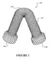
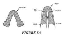
図1は、弛緩状態における本発明の第1の好ましい実施形態の接続装置の正面図を示している。接続装置は、第1の造瘻を第2の造瘻に接続し、内容物を第1の造瘻から第2の造瘻に移送するのに適している。Figure 1 shows a front view of a first preferred embodiment of a connection device of the present invention in a relaxed state. The connection device is suitable for connecting a first ostomy to a second ostomy and transferring contents from the first ostomy to the second ostomy.
図1からわかるように、接続装置(100)は、囲い壁を有する、すなわち管状であり且つ湾曲部(104)を有する本体部(102)を備える。第1の開口端部(106)および第2の開口端部(108)がある。As can be seen in FIG. 1, the connection device (100) comprises a body portion (102) having an enclosed wall, i.e., tubular, and having a curved portion (104). There is a first open end (106) and a second open end (108).
本体部(102)は、可撓性および弾力性を有し、したがって形状記憶および/または弾力性を有する材料から構成され、すなわち、本体部(102)は、元の湾曲形状に復元する特性を有する。その弛緩状態では、本体部(102)は、U字形またはV字形または他の任意の弓形とすることができる。The body portion (102) is constructed from a material that is flexible and resilient, and thus has shape memory and/or elasticity, i.e., the body portion (102) has the property of returning to its original curved shape. In its relaxed state, the body portion (102) can be U-shaped or V-shaped or any other arcuate shape.
図1に示すように、第1の開口端部(106)および第2の開口端部(108)は、フレア状/僅かに漏斗状であるため、これらのフレア端部のそれぞれの内径は、フレア状でない本体部(102)の内径よりも大きい。第1の開口端部(106)および第2の開口端部(108)のフレアは、装置(100)が造瘻またはストーマの内部に挿入されるとき、接続装置(100)の固定を支援する。As shown in FIG. 1, the first open end (106) and the second open end (108) are flared/slightly funnel-shaped such that the inside diameter of each of these flared ends is larger than the inside diameter of the non-flared body portion (102). The flare of the first open end (106) and the second open end (108) helps secure the connection device (100) when the device (100) is inserted inside the ostomy or stoma.
そのようなフレアはまた、流体または腸内容物の漏洩が接続装置(100)の縁の周りで発生しないように、オリフィスまたは管腔の内壁を密封するのに役立つ。これについては、後に詳細に説明する。Such a flare also serves to seal the inner wall of the orifice or lumen so that leakage of fluids or intestinal contents does not occur around the edges of the connection device (100), as will be described in more detail below.
図1に示すように、接続装置のこの第1の好ましい実施形態の本体部(102)は、中空の一般に円筒形の覆われたメッシュ構造である。本体部(102)の構造は、好ましくは本体部(102)の少なくとも大部分まで、最も好ましくは図示のように本体部(102)全体まで延在する一連のワイヤまたはフィラメントを含む。As shown in FIG. 1, the body portion (102) of this first preferred embodiment of the connection device is a hollow, generally cylindrical, covered mesh structure. The structure of the body portion (102) preferably includes a series of wires or filaments that extend through at least a majority of the body portion (102), and most preferably through the entire body portion (102) as shown.
メッシュ構造のフィラメントは、好ましくは弾性形状記憶合金ワイヤ、例えばニチノールなどの弾性材料用に構成されたものである。あるいは、本体部(102)は、シリコーンで覆われたニチノールから形成される。他の材料は、形状記憶ポリマーもしくは金属、または単に弾性材料、または挿入のために折り畳まれて保持のために拡張する何らかの能力を有する他の材料を含むことができる。The filaments of the mesh structure are preferably configured for elastic materials such as elastic shape memory alloy wires, e.g., Nitinol. Alternatively, the body portion (102) is formed from Nitinol covered with silicone. Other materials may include shape memory polymers or metals, or simply elastic materials, or other materials that have some ability to fold for insertion and expand for retention.
本体壁は、メッシュが折り畳まれたり拡張したりすると、壁も移動して、所望の本体プロファイルを提供するようにメッシュに関連付けられている。可撓性メッシュは、本体壁の内部または外部に配置されることが予想される。また、可撓性メッシュが本体壁と他の層または本体をメッシュに関連付けることを可能にする他のレイアップとの間に配置されることも予想される。The body walls are associated with the mesh such that as the mesh folds or expands, the walls also move to provide the desired body profile. It is anticipated that the flexible mesh will be placed on the interior or exterior of the body walls. It is also anticipated that the flexible mesh will be placed between the body walls and other layers or other layups that allow the body to be associated with the mesh.
好ましくは、壁は、壁に結合されており、そのため、メッシュが拡張または収縮すると、壁はメッシュと共に移動する。Preferably, the walls are bonded to the mesh so that as the mesh expands or contracts, the walls move with the mesh.
結果として得られる構造は、腸の内容物が通過できるチューブであるが、弾力性を有し、チューブをその自然な状態でその形状を保持する能力、および/または展開前に圧縮/折り畳む能力をチューブに与える。フィラメントは、編み組んだ形態で連続して一体に織り上げられることができるが、構造は、織り構造に限定されるものではなく、これらに限定されるものではないが、溶接、かぎ針編み、編み物、結束、縫合、または任意のそのようなメッシュまたは相互接続された構造を製造するその他の適切な方法など、他の同様の加工を含む。The resulting structure is a tube through which the intestinal contents can pass, but has elasticity, giving the tube the ability to retain its shape in its natural state and/or the ability to be compressed/folded prior to deployment. The filaments can be woven together continuously in a braided form, although the structure is not limited to woven structures and includes other similar processes such as, but not limited to, welding, crocheting, knitting, tying, suturing, or other suitable methods of producing any such mesh or interconnected structure.
第2の好ましい実施形態
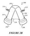
図2aは、弛緩状態における本発明の第2の好ましい実施形態の接続装置の正面図を示している。 Second Preferred Embodiment Figure 2a shows a front view of a connecting device of a second preferred embodiment of the present invention in a relaxed state.
図1に示す第1の好ましい実施形態と同様に、この第2の好ましい実施形態にかかる接続装置(200)は、管状であり且つ湾曲部分(204)を有する本体部(202)を備える。第1の開口端部(206)および第2の開口端部(208)がある。Similar to the first preferred embodiment shown in FIG. 1, the connection device (200) of this second preferred embodiment includes a body portion (202) that is tubular and has a curved portion (204). There is a first open end (206) and a second open end (208).
本体部(202)は、可撓性および弾力性を有し、したがって形状記憶および/または弾力性を有する材料から構成され、すなわち、本体部(202)は、元の湾曲形状に復元する特性を有する。その弛緩状態では、本体部(202)は、U字形またはV字形または他の任意の弓形からなることができる。The body portion (202) is constructed from a material that is flexible and resilient, and thus has shape memory and/or elasticity, i.e., the body portion (202) has the property of returning to its original curved shape. In its relaxed state, the body portion (202) can be U-shaped or V-shaped or any other arcuate shape.
第1の開口端部(206)および第2の開口端部(208)は、フレア状/僅かに漏斗状であるため、これらのフレア端部のそれぞれの内径は、フレア状でない本体部(202)の内径よりも大きい。第1の開口端部(206)および第2の開口端部(208)のフレアは、装置(200)が患者の身体上で造瘻またはストーマの内部に挿入されるとき、接続装置(200)の固定を支援する。そのようなフレアはまた、流体または腸内容物の漏洩が接続装置(200)の縁の周りで発生しないように、オリフィスまたは管腔の内壁を密封するのに役立つ。The first open end (206) and the second open end (208) are flared/slightly funnel-shaped such that the inner diameter of each of these flared ends is larger than the inner diameter of the non-flared body portion (202). The flare of the first open end (206) and the second open end (208) helps secure the connecting device (200) when the device (200) is inserted inside an ostomy or stoma on the patient's body. Such a flare also helps seal the inner wall of the orifice or lumen so that leakage of fluids or bowel contents does not occur around the edges of the connecting device (200).
図1に示されるような装置(200)の実施形態とは異なり、接続装置(202)の本体部(202)は、メッシュ強化構造として形成されず、代わりに非メッシュ管状構造として形成される。本体部(202)に適した構成材料のいくつかの例は、医療グレードのシリコーン、シリコーンゴム、ポリウレタン、PVCまたはラテックスゴムである。他の材料は、形状記憶ポリマーもしくは金属、または単に弾性材料、または挿入のために折り畳まれて保持のために拡張する何らかの能力を有する他の材料を含むことができる。装置(200)の本体部(202)または本体部(202)の一部は、透明または半透明または不透明のいずれかとすることができる。Unlike the embodiment of the device (200) as shown in FIG. 1, the body portion (202) of the connecting device (202) is not formed as a mesh reinforced structure, but instead as a non-mesh tubular structure. Some examples of suitable construction materials for the body portion (202) are medical grade silicone, silicone rubber, polyurethane, PVC or latex rubber. Other materials can include shape memory polymers or metals, or simply elastic materials, or other materials that have some ability to fold for insertion and expand for retention. The body portion (202) of the device (200), or portions of the body portion (202), can be either transparent or translucent or opaque.
装置(200)は、図2bに示すように、フレア状の開口端部(206および208)の上に1つ以上の突起(216)を必要に応じて備えることができる。上述したように、第1の開口端部(206)および第2の開口端部(208)のフレアは、身体オリフィスまたはストーマへの接続装置(200)の固定を支援する。これらの任意の突起(216)は、固定をさらに支援し、より強力なグリップを容易にすることができる。両端部(206および208)の代わりに、突起(216)は、第1の開口端部(206)および第2の開口端部(208)の一方のみの上に必要に応じて形成されてもよい。突起(216)は、周方向突起(図示せず)の形態であってもよく、すなわち、それらは、フレア開口端部(206および208)の直上の本体部の外面の周囲に延在してもよい。The device (200) may optionally include one or more projections (216) on the flared open ends (206 and 208), as shown in FIG. 2b. As mentioned above, the flare of the first open end (206) and the second open end (208) aids in anchoring the connecting device (200) to the body orifice or stoma. These optional projections (216) may further aid in anchoring and facilitate a stronger grip. Instead of both ends (206 and 208), the projections (216) may optionally be formed on only one of the first open end (206) and the second open end (208). The projections (216) may be in the form of circumferential projections (not shown), i.e., they may extend around the exterior surface of the body portion directly above the flared open ends (206 and 208).
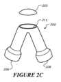
図2bに示すように、装置(200)は、必要に応じて、湾曲部分の頂点またはその近くの少なくとも1つのキャップ(205)および/または本体部(202)の外面上の1つ以上の取り付け手段(215)を備える。As shown in FIG. 2b, the device (200) optionally includes at least one cap (205) at or near the apex of the curved portion and/or one or more attachment means (215) on the exterior surface of the body portion (202).
図2b~図2dは、本発明で使用することができるキャップ構成のいくつかの例を示している。好ましくは、キャップ(205)は、取り外し可能な磁気キャップである。好ましくは、キャップ(205)と係合する本体部(202)の部分もまた、キャップ(205)が本体部(202)から磁気的に着脱されることができるように、磁性材料から構成される。Figures 2b-2d show some examples of cap configurations that can be used with the present invention. Preferably, cap (205) is a removable magnetic cap. Preferably, the portion of body portion (202) that engages cap (205) is also constructed from a magnetic material such that cap (205) can be magnetically attached and detached from body portion (202).
しかしながら、キャップ(205)を本体部(202)に係合するための他の代替手段、例えば、限定されるものではないが、ヒンジ接続、ねじ接続、付勢手段、ファスナまたはそれらの組み合わせによる係合などが同様に可能である。キャップ(205)またはキャップ(205)の少なくとも一部は、栓タイプであってもよく、すなわち、キャップ(205)の少なくとも一部が圧縮または圧搾され、内側部(211)の入口ポートを通過し、挿入されると、キャップ(205)の圧縮部分が本体部(202)の内面に対して自己拡張し、それによりシールを形成することを可能にすることができるように、柔軟な弾性材料から構成されてもよい。However, other alternative means for engaging the cap (205) to the body portion (202) are possible as well, such as, but not limited to, a hinged connection, a threaded connection, engagement by a biasing means, a fastener, or combinations thereof. The cap (205) or at least a portion of the cap (205) may be of the plug type, i.e., constructed from a soft, elastic material such that at least a portion of the cap (205) can be compressed or squeezed to allow the compressed portion of the cap (205) to self-expand against the inner surface of the body portion (202) when inserted through the inlet port of the inner portion (211), thereby forming a seal.
キャップ(205)を有することにより、本体部(202)の内側部(211)へのアクセスが可能になる。本体部(202)の内部へのそのようなアクセスを有することは、装置(200)の内側部(211)の洗浄、および装置(200)が患者の身体内に埋め込まれたときに装置(200)の内側部(211)からの任意の閉塞または潜在的な閉塞の解放または洗い流しを支援することができる。Having the cap (205) allows access to the interior (211) of the body (202). Having such access to the interior of the body (202) can aid in cleaning the interior (211) of the device (200) and in releasing or flushing any blockages or potential blockages from the interior (211) of the device (200) when the device (200) is implanted within the patient's body.
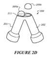
1つのキャップの代わりに、装置(200)は、複数のキャップ、例えば、図2dに示されるものなどの2つのキャップ(205a、205b)を有してもよい。その実施形態では、第1のキャップ(205a)は、装置(200)の左側(201)の内側部(211)へのアクセスを可能にし、キャップ(205b)は、装置(200)の右側(203)の内側部(211)へのアクセスを可能にする。そのようなアクセスを有することは、左側(201)および右側(203)の内側部(211)または装置(200)の双方の洗浄、ならびに装置(200)が患者の身体内に埋め込まれたときに装置(200)の内側部(211)からの閉塞または潜在的な閉塞(200)の解放または洗い流しを支援することができる。好ましくは、キャップ(205a、205b)は取り外し可能な磁気キャップである。好ましくは、キャップ(205a、205b)と係合する本体部(202)の部分は、キャップ(205a、205b)が本体部(202)から磁気的に着脱されることができるように、磁性材料から構成される。しかしながら、キャップ(205a、205b)を本体部に係合するための他の代替手段、例えば、限定されるものではないが、ヒンジ接続、ねじ接続、付勢手段、ファスナまたはそれらの組み合わせによる係合などが同様に可能である。あるいは、キャップ(205a、205b)またはその一部の少なくとも1つは、上述したように栓タイプであってもよい。Instead of one cap, the device (200) may have multiple caps, for example two caps (205a, 205b) such as those shown in FIG. 2d. In that embodiment, the first cap (205a) allows access to the interior (211) of the left side (201) of the device (200) and the cap (205b) allows access to the interior (211) of the right side (203) of the device (200). Having such access can aid in cleaning of both the left (201) and right (203) interiors (211) or the device (200), as well as in releasing or flushing occlusions or potential occlusions (200) from the interior (211) of the device (200) when the device (200) is implanted in the patient's body. Preferably, the caps (205a, 205b) are removable magnetic caps. Preferably, the portions of the body portion (202) that engage the caps (205a, 205b) are constructed from a magnetic material such that the caps (205a, 205b) can be magnetically attached and detached from the body portion (202). However, other alternative means for engaging the caps (205a, 205b) to the body portion are possible as well, such as, but not limited to, a hinged connection, a threaded connection, a biasing means, fasteners, or combinations thereof. Alternatively, at least one of the caps (205a, 205b) or portions thereof may be of the plug type as described above.
各キャップの取り付けは、少なくとも耐漏洩性であることが好ましいことが理解されよう。It will be appreciated that it is preferred that each cap attachment be at least leak-proof.
図2bに示すように、接続装置(200)は、主に、取り付け手段(215)に取り付けるのに適している対応手段を有する、ストーマベルトなどの補助装置(図示せず)への接続のためのループの形態の取り付け手段(215)を必要に応じて含むことができる。取り付け手段(215)は、フック、クリップ、フックおよびループファスナなどであるがこれらに限定されるものではない、補助装置に取り付けるための任意の他の適切な取り付け手段とすることができる。As shown in FIG. 2b, the connection device (200) may optionally include an attachment means (215) mainly in the form of a loop for connection to an auxiliary device (not shown), such as a stoma belt, having a corresponding means suitable for attachment to the attachment means (215). The attachment means (215) may be any other suitable attachment means for attachment to an auxiliary device, such as but not limited to hooks, clips, hook and loop fasteners, etc.
メッシュ強化構造を有する図1の接続装置(100)は、フレア状の開口端部(106、108)および/または少なくとも1つのキャップおよび/または図2b~図2dを参照して上述したものと同様の少なくとも1つの取り付け手段の上に突起を含むように同様に設計されることができる。キャップは、磁性もしくは栓タイプ、または上述したような任意の他の適切なタイプとすることができ、好ましくは、本体部(102)のメッシュ構造の頂点に配置される。同様に、装置(100)はまた、1つ以上の取り付け手段を含むように設計されることができる。上述したものと同様に、装置(100)の取り付け手段は、本体部(202)を形成する同じメッシュ構造の一部として形成されてもよく、または任意の適切な手段によって本体部に接続される他の構造とすることができる。The connection device (100) of FIG. 1 having a mesh reinforcement structure can similarly be designed to include protrusions on the flared open ends (106, 108) and/or at least one cap and/or at least one attachment means similar to those described above with reference to FIGS. 2b-2d. The cap can be of magnetic or plug type or any other suitable type as described above, and is preferably located at the apex of the mesh structure of the body portion (102). Similarly, the device (100) can also be designed to include one or more attachment means. As described above, the attachment means of the device (100) can be formed as part of the same mesh structure forming the body portion (202) or can be other structures connected to the body portion by any suitable means.
上述したように、キャップ(205)および/または取り付け手段(215)および/または突起(216)は、純粋に任意である。キャップ(215)が存在しないそれほど複雑ではない設計では、代替の技術によって内容物を洗い流して閉塞または潜在的な閉塞を引き起こすことがさらに可能である。例えば、患者には、影響を受けた胃腸閉塞を希釈して洗い流すことができる経口溶液(経口「ガストログラフィン」またはポリエチレングリコールなど)が与えられてもよい。あるいは、閉塞または潜在的な閉塞の場合に、装置(100、200)を完全に取り外して交換することも可能である。あるいは、装置(100、200)の本体部(102、202)は、可撓性材料から構成されているため、外部から装置(102、202)に外力を加えることによって圧搾するか、または振動することもまた、任意の閉塞または潜在的な閉塞の除去の洗浄を支援することができる。必要に応じて、装置(100、200)のライニングは、内容物の通過を助け、閉塞の可能性を低減するために、潤滑材料または潤滑ライナーによってコーティングされてもよい。例えば、ポリテトラフルオロエチレン(またはPTFE)または適切なナノ粒子または生体適合性材料を、潤滑材料として使用することができる。As mentioned above, the cap (205) and/or the attachment means (215) and/or the protrusions (216) are purely optional. In less complex designs where the cap (215) is absent, it is still possible to flush the contents by alternative techniques to cause blockages or potential blockages. For example, the patient may be given an oral solution (such as oral "gastrografin" or polyethylene glycol) that can dilute and flush the affected gastrointestinal blockage. Alternatively, it is also possible to completely remove and replace the device (100, 200) in case of blockage or potential blockage. Alternatively, since the body (102, 202) of the device (100, 200) is constructed from a flexible material, squeezing or vibrating by applying an external force to the device (102, 202) from the outside can also assist in cleaning the removal of any blockage or potential blockage. If necessary, the lining of the device (100, 200) may be coated with a lubricating material or lubricating liner to aid in the passage of the contents and reduce the possibility of blockage. For example, polytetrafluoroethylene (or PTFE) or suitable nanoparticles or biocompatible materials can be used as the lubricating material.
第3および第4の好ましい実施形態
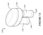
図3および図4は、弛緩状態における本発明の第3の好ましい実施形態および第4の好ましい実施形態の接続装置(300)の斜視図をそれぞれ示している。 Third and Fourth Preferred Embodiments Figures 3 and 4 respectively show perspective views of a connecting device (300) according to the third and fourth preferred embodiments of the present invention in a relaxed state.
図3に示すように、第3の好ましい実施形態の装置(300)の本体部(300)は、形状が管状であり、外面(304)、内面(305)、および長手方向に対向する第1および第2の開口端部(306および308)を有する。As shown in FIG. 3, the body portion (300) of the third preferred embodiment device (300) is tubular in shape and has an outer surface (304), an inner surface (305), and first and second longitudinally opposed open ends (306 and 308).
本体部(302)は、可撓性且つ弾力性を有し、したがって形状記憶および/または弾力性を有する材料から構成され、すなわち、本体部(302)は、元の細長形状に復元する特性を有する。The body portion (302) is constructed from a material that is flexible and resilient, and thus has shape memory and/or elasticity, i.e., the body portion (302) has the property of returning to its original elongated shape.
第1の開口端部(306)および第2の開口端部(308)は、フレア状/僅かに漏斗状であるため、これらのフレア端部のそれぞれの内径は、フレア状でない本体部(302)の内径よりも大きい。第1の開口端部(306)および第2の開口端部(308)のフレアは、装置(200)が患者の身体上で造瘻またはストーマの内部に挿入されるとき、接続装置(300)の固定を支援する。そのようなフレアはまた、流体または腸内容物の漏洩が接続装置(300)の縁の周りで発生しないように、オリフィスまたは管腔の内壁を密封するのに役立つ。The first open end (306) and the second open end (308) are flared/slightly funnel-shaped such that the inner diameter of each of these flared ends is larger than the inner diameter of the non-flared body portion (302). The flare of the first open end (306) and the second open end (308) helps secure the connecting device (300) when the device (200) is inserted inside an ostomy or stoma on the patient's body. Such a flare also helps seal the inner wall of the orifice or lumen so that leakage of fluids or bowel contents does not occur around the edges of the connecting device (300).
第1の好ましい実施形態の装置(100)と同様に、接続装置(300)のこの第3の好ましい実施形態の本体部(302)は、中空の一般に円筒形のメッシュ強化構造である。本体部(302)の構造は、好ましくは本体部(302)の長さの少なくとも大部分まで、最も好ましくは図示のように本体部(302)の全長まで延在する一連のワイヤまたはフィラメントを含む。As with the device (100) of the first preferred embodiment, the body portion (302) of this third preferred embodiment of the connection device (300) is a hollow, generally cylindrical, mesh-reinforced structure. The structure of the body portion (302) preferably includes a series of wires or filaments that extend through at least a majority of the length of the body portion (302), and most preferably the entire length of the body portion (302) as shown.
メッシュ構造のフィラメントは、好ましくは弾性形状記憶合金ワイヤ、例えばニチノールなどの弾性材料用に構成されたものである。あるいは、本体部(102)は、シリコーンで覆われたニチノールから形成される。他の材料は、形状記憶ポリマーもしくは金属、または単に弾性材料、または挿入のために折り畳まれて保持のために拡張する何らかの能力を有する他の材料を含むことができる。フィラメントは、編み組んだ形態で連続して一体に織り上げられることができるが、構造は、織り構造に限定されるものではなく、これらに限定されるものではないが、編み物、溶接、かぎ針編み、縫合、結束、または任意のそのようなメッシュまたは相互接続された構造を製造するその他の適切な方法など、他の同様の加工を含む。The filaments of the mesh structure are preferably configured for elastic materials such as elastic shape memory alloy wires, e.g., Nitinol. Alternatively, the body portion (102) is formed from Nitinol covered with silicone. Other materials can include shape memory polymers or metals, or simply elastic materials, or other materials that have some ability to collapse for insertion and expand for retention. The filaments can be woven together continuously in a braided form, but the structure is not limited to a woven structure and includes other similar processes such as, but not limited to, knitting, welding, crocheting, sewing, tying, or other suitable methods of manufacturing any such mesh or interconnected structure.
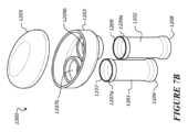
図4に示すように、第4の好ましい実施形態の装置(400)は、上述した第3の好ましい実施形態の装置(300)と実質的に同様であり、したがって、装置(300)に関する上記の説明の大部分は、装置(400)に同様に当てはまる。しかしながら、図3に示されるような装置(300)の実施形態とは異なり、接続装置(402)の本体部(402)は、メッシュ強化構造を含まず、代わりに非メッシュ管状構造として形成される。本体部(402)に適した構成材料のいくつかの例は、医療グレードのシリコーン、シリコーンゴム、ポリウレタン、PVCまたはラテックスゴムである。他の材料は、形状記憶ポリマーもしくは金属、または単に弾性材料、または挿入のために折り畳まれて保持のために拡張する何らかの能力を有する他の材料を含むことができる。装置(400)の本体部(402)または本体部(402)の一部は、透明または半透明または不透明のいずれかとすることができる。As shown in FIG. 4, the fourth preferred embodiment device (400) is substantially similar to the third preferred embodiment device (300) described above, and therefore most of the above description regarding device (300) applies to device (400) as well. However, unlike the embodiment of device (300) as shown in FIG. 3, the body portion (402) of the connecting device (402) does not include a mesh reinforcing structure, but is instead formed as a non-mesh tubular structure. Some examples of suitable construction materials for the body portion (402) are medical grade silicone, silicone rubber, polyurethane, PVC, or latex rubber. Other materials may include shape memory polymers or metals, or simply elastic materials, or other materials that have some ability to fold for insertion and expand for retention. The body portion (402) of device (400), or portions of the body portion (402), may be either transparent, translucent, or opaque.
図示されていないが、第3および第4の好ましい実施形態の装置(300および400)は、図2b~図2dを参照して上述したのと同様の方法で、突起および/またはキャップおよび/または1つ以上の取り付け手段を必要に応じて含むことができる。キャップは、装置(300および400)が、U字形または略U字形のように弓形に湾曲されるように、細長本体部(302および402)の中央またはその近くの外面上に配置されることができ、キャップは、湾曲部分の頂点またはその近くに現れる。同様に、1つ以上の取り付け手段は、外面上のフレア部と細長本体部の中央との間に配置されることができる。Although not shown, the devices (300 and 400) of the third and fourth preferred embodiments may optionally include protrusions and/or caps and/or one or more attachment means in a manner similar to that described above with reference to Figures 2b-2d. The caps may be located on the exterior surface at or near the center of the elongated body portion (302 and 402) such that the devices (300 and 400) are curved in an arcuate shape, such as a U-shape or approximately U-shape, with the cap appearing at or near the apex of the curved portion. Similarly, one or more attachment means may be located between the flared portion on the exterior surface and the center of the elongated body portion.
使用中(すなわち、埋め込み中)、第3および第4の好ましい実施形態の装置(300および400)は、外力を加えることにより、U字形もしくはV字形または略U字形もしくはV字形などの弓形に曲げられるように構成される。曲げられたとき、第3の好ましい実施形態の装置(300)は、第1の好ましい実施形態の装置(100)と同様に見えることができる。同様に、第4の好ましい実施形態の装置(400)は、本発明の第2の好ましい実施形態の装置(200)と同様に見えることができる。外力が解放されると、第3の好ましい実施形態の装置(300)は、図3に示されるようにその初期の曲がらない状態に戻る傾向があり、第4の好ましい実施形態の装置(400)は、図4に示されるようにその初期の曲がらない状態に戻る傾向がある。この弾性は、腸壁に力を加えることにより、装置を適切な位置に保つのに役立つように作用する。During use (i.e., during implantation), the third and fourth preferred embodiment devices (300 and 400) are configured to be bent into an arched shape, such as a U-shape or V-shape or a generally U-shape or V-shape, by application of an external force. When bent, the third preferred embodiment device (300) can appear similar to the first preferred embodiment device (100). Similarly, the fourth preferred embodiment device (400) can appear similar to the second preferred embodiment device (200) of the present invention. When the external force is released, the third preferred embodiment device (300) tends to return to its initial unbent state as shown in FIG. 3, and the fourth preferred embodiment device (400) tends to return to its initial unbent state as shown in FIG. 4. This elasticity acts to help keep the device in place by applying a force to the intestinal wall.
第5の好ましい実施形態
図7a~図7bは、本発明の第5の好ましい実施形態の接続装置(1200)を示している。 Fifth Preferred Embodiment Figures 7a-7b show a fifth preferred embodiment connection device (1200) of the present invention.
本発明の第5の好ましい実施形態の接続装置(1200)は、上述した接続装置(100、200、300、および400)の代替例を提供する。The fifth preferred embodiment of the connection device (1200) of the present invention provides an alternative to the connection devices (100, 200, 300, and 400) described above.
この好ましい実施形態における接続装置(1200)は、2つの管状部材、すなわち、第1の管状部材(1201)および第2の管状部材(1202)、ならびに中空本体部材/中間部材(1203)を備える。The connection device (1200) in this preferred embodiment comprises two tubular members, a first tubular member (1201) and a second tubular member (1202), and a hollow body member/intermediate member (1203).
第1の管状部材(1201)は、長手方向に対向する第1および第2の開口端部(1206および1207)を備える。同様に、第2の管状部材もまた、長手方向に対向する第1および第2の開口端部(1208および1209)を備える。The first tubular member (1201) has first and second longitudinally opposed open ends (1206 and 1207). Similarly, the second tubular member also has first and second longitudinally opposed open ends (1208 and 1209).
管状部材(1201および1202)は、好ましくは、可撓性および弾力性を有し、したがって形状記憶および/または弾性を有する材料から構成され、すなわち、管状部材は、元の弛緩した形状に復元する特性を有する。The tubular members (1201 and 1202) are preferably constructed from a material that is flexible and resilient, and thus has shape memory and/or elasticity, i.e., the tubular members have the property of returning to their original relaxed shape.
管状部材(1201および1202)の第1の開口端部(1206および1208)は、好ましくはフレア状/僅かな漏斗状であり、したがって、それらのフレア端部のそれぞれの外径は、フレア状ではない本体部の内径よりも大きい。第1の開口端部(1206)および第2の開口端部(1208)のフレアは、装置(1200)が患者の身体上で造瘻またはストーマの内部に挿入されるとき、接続装置(1200)の固定を支援する。そのようなフレアはまた、流体または腸内容物の漏洩が接続装置(1200)の縁の周りで発生しないように、オリフィスまたは管腔の内壁を密封するのに役立つ。The first open ends (1206 and 1208) of the tubular members (1201 and 1202) are preferably flared/slightly funnel-shaped, such that the outer diameter of each of those flared ends is greater than the inner diameter of the non-flared body portion. The flare of the first open end (1206) and the second open end (1208) helps secure the connecting device (1200) when the device (1200) is inserted inside an ostomy or stoma on the patient's body. Such a flare also helps seal the inner wall of the orifice or lumen so that leakage of fluids or bowel contents does not occur around the edges of the connecting device (1200).
図12bに示すように、管状部材(1201および1202)の第2の開口端部(1207および1209)は、好ましくは、カラーまたはフレア部(1207aおよび1209a)を有する。As shown in FIG. 12b, the second open ends (1207 and 1209) of the tubular members (1201 and 1202) preferably have a collar or flare (1207a and 1209a).
中空本体部材(1203)は、図7bに示されるような接続構造の形態である。接続構造は、図12bに示すように、2つの構成、すなわち、入口(1207b)および出口(1209b)を備える。第1の管状部材(1201)の第2の開口端部(1207)および/またはカラーまたはフレア部(1207a)は、入口(1207b)によって固定(連結/挿入)されるように適合され、第2の管状部材(1202)の第2の開口端部(1209)および/またはカラーまたはフレア部(1209b)は、出口(1209b)によって固定(連結/挿入)されるように適合されている。例えば、少なくとも第2の開口端部(1207および1209)および/またはカラーまたはフレア部(1207aおよび1209a)は、入口(1207b)および出口(1209b)を介して挿入するために折り畳まれることができ、挿入されると、それらは、それぞれの入口(1207b)および出口(1209b)に保持するためにそれらの初期の弛緩または非折り畳み状態に拡張することができる。少なくともこの理由により、管状部材(1201および1202)は、挿入のために折り畳まれた後、それらの弛緩、すなわち保持のための初期の非折り畳み位置に拡張する能力を有する材料から構成されることが好ましい。適切な材料は、上述した第1および第3の実施形態(100および300)、または第2および第4(200および400)の実施形態の構築について上述したのと同じ材料とすることができる。The hollow body member (1203) is in the form of a connection structure as shown in FIG. 7b. The connection structure comprises two configurations, an inlet (1207b) and an outlet (1209b), as shown in FIG. 12b. The second open end (1207) and/or collar or flared portion (1207a) of the first tubular member (1201) is adapted to be secured (coupled/inserted) by the inlet (1207b), and the second open end (1209) and/or collar or flared portion (1209b) of the second tubular member (1202) is adapted to be secured (coupled/inserted) by the outlet (1209b). For example, at least the second open ends (1207 and 1209) and/or collars or flares (1207a and 1209a) can be folded for insertion through the inlets (1207b) and outlets (1209b), and once inserted, they can expand to their initial relaxed or unfolded state for retention in the respective inlets (1207b) and outlets (1209b). For at least this reason, the tubular members (1201 and 1202) are preferably constructed from materials that have the ability to be folded for insertion and then expand to their relaxed, i.e., initial unfolded position for retention. Suitable materials can be the same materials as described above for the construction of the first and third (100 and 300) or second and fourth (200 and 400) embodiments described above.
管状部材(1201および1202)は、第1および第3の実施形態(100および300)について上述したものと同様のメッシュ構造、または第2および第4の実施形態(200および400)について上述したものと同様の非メッシュ構造とすることができる。あるいは、管状部材(1201または1202)の1つは、メッシュ構造であってもよく、他の管状部材(1201または1202)は、非メッシュ構造であってもよい。The tubular members (1201 and 1202) can be of a mesh structure similar to that described above for the first and third embodiments (100 and 300), or of a non-mesh structure similar to that described above for the second and fourth embodiments (200 and 400). Alternatively, one of the tubular members (1201 or 1202) can be of a mesh structure and the other tubular member (1201 or 1202) can be of a non-mesh structure.
カラーまたはフレア部(1207aおよび1209a)は、管状部材(1201および1202)が入口(1207b)および出口(1209b)を介して挿入/連結されるとき、管状部材(1201および1202)の固定を支援する。そのようなフレアはまた、流体または腸内容物の漏洩が管状部材(1201および1202)の縁の周囲で発生しないように、入口(1207b)および出口(1209b)の内壁を密封するのに役立つ。したがって、カラーまたはフレア部(1207および1209a)が好ましい。しかしながら、管状部材(1201および1202)を入口(1207b)および出口(1209b)に取り付けるための任意のその他の適切な代替手段、例えば、ねじ接続による取り付け、クリップまたはスナップフィット接続、ファスナを使用した取り付け、磁気接続などが可能である。The collars or flared portions (1207a and 1209a) aid in securing the tubular members (1201 and 1202) when they are inserted/coupled through the inlets (1207b) and outlets (1209b). Such flares also aid in sealing the inner walls of the inlets (1207b) and outlets (1209b) so that leakage of fluids or intestinal contents does not occur around the edges of the tubular members (1201 and 1202). Thus, the collars or flared portions (1207 and 1209a) are preferred. However, any other suitable alternative means for attaching the tubular members (1201 and 1202) to the inlets (1207b) and outlets (1209b) are possible, such as attachment by threaded connections, clip or snap fit connections, attachment using fasteners, magnetic connections, etc.
あるいはさらに、管状部材(1201、1202)は、架設中空本体部材1203と一体であってもよい。Alternatively, the tubular members (1201, 1202) may be integral with the erected
中間部材(1203)は、好ましくは、管状部材と同じ材料から、または異なる材料から構成される。好ましくは、中空本体部材(1203)またはその少なくとも一部は、第1および第3の実施形態(100および300)について上述したものと同様のメッシュ構造、または第2および第4の実施形態(200および400)について上述したものと同様の非メッシュ構造である。適用されるとき、中間部材はまた、ストーマオリフィスを覆い、したがって損傷または摩耗から保護することが好ましい。The intermediate member (1203) is preferably constructed from the same material as the tubular member or from a different material. Preferably, the hollow body member (1203), or at least a portion thereof, is of a mesh construction similar to that described above for the first and third embodiments (100 and 300), or of a non-mesh construction similar to that described above for the second and fourth embodiments (200 and 400). When applied, the intermediate member also preferably covers the stoma orifice, thus protecting it from damage or wear.
必要に応じて、装置(1200)は、取り外し可能であるキャップ(1205)を備える。Optionally, the device (1200) includes a removable cap (1205).
いくつかの好ましい設計では、キャップは、磁気キャップである。好ましくは、キャップ(1205)と係合する中間部材(1203)の部分もまた、キャップ(1205)を中間部材(1203)に磁気的に取り付けおよび取り外しできるように、磁性材料から構成される。しかしながら、キャップ(1203)を中間部材(1203)に係合するための他の代替手段、例えば、限定されるものではないが、ヒンジ接続、ねじ接続、クリップ機構、付勢手段、ファスナまたはそれらの組み合わせによる係合などが同様に可能である。キャップ(1205)またはキャップ(1205)の少なくとも一部は、図2b~図2dを参照して上述したように栓タイプであってもよい。In some preferred designs, the cap is a magnetic cap. Preferably, the portion of the intermediate member (1203) that engages the cap (1205) is also constructed from a magnetic material such that the cap (1205) can be magnetically attached and detached from the intermediate member (1203). However, other alternative means for engaging the cap (1203) to the intermediate member (1203) are possible as well, such as, but not limited to, a hinged connection, a threaded connection, a clip mechanism, a biasing means, a fastener, or a combination thereof. The cap (1205) or at least a portion of the cap (1205) may be of the plug type as described above with reference to Figures 2b-2d.
キャップ(1205)を有することは、中空本体部材(1203)および管状部材の内側部へのアクセスを可能にする。内側部へのそのようなアクセスを有することは、内側部の洗浄、および装置(1200)が患者の身体内に埋め込まれたときに装置(1200)の内側部からの任意の閉塞または潜在的な閉塞の解放または洗い流しを支援することができる。Having the cap (1205) allows access to the interior of the hollow body member (1203) and the tubular member. Having such access to the interior can aid in cleaning the interior and releasing or flushing any blockages or potential blockages from the interior of the device (1200) when the device (1200) is implanted within the patient's body.
キャップ(1205)が存在しないそれほど複雑ではない設計では、代替の技術によって内容物を洗い流して閉塞または潜在的な閉塞を引き起こすことがさらに可能である。例えば、患者には、影響を受けた胃腸閉塞を希釈して洗い流すことができる経口溶液(経口「ガストログラフィン」またはポリエチレングリコールなど)が与えられてもよい。In less complex designs where the cap (1205) is absent, it is still possible to flush the contents out by alternative techniques to cause blockages or potential blockages. For example, the patient may be given an oral solution (such as oral "gastrografin" or polyethylene glycol) that can dilute and flush out the affected gastrointestinal blockage.
あるいは、閉塞または潜在的な閉塞の場合に、装置(100、200)を完全に取り外して交換することも可能である。あるいは、外部から装置(1200)に外力を加えることによって圧搾するか、または振動することもまた、任意の閉塞または潜在的な閉塞の除去の洗浄を支援することができる。必要に応じて、装置(1200)のライニングは、内容物の通過を助け、閉塞の可能性を低減するために、潤滑材料または潤滑ライナーによってコーティングされてもよい。例えば、ポリテトラフルオロエチレン(またはPTFE)または適切なナノ粒子または生体適合性材料を、潤滑材料として使用することができる。Alternatively, the device (100, 200) may be completely removed and replaced in the event of an obstruction or potential obstruction. Alternatively, squeezing or vibrating the device (1200) from the outside may also assist in cleaning and removing any obstructions or potential obstructions. If desired, the lining of the device (1200) may be coated with a lubricous material or liner to aid in the passage of contents and reduce the possibility of obstruction. For example, polytetrafluoroethylene (or PTFE) or suitable nanoparticles or biocompatible materials may be used as the lubricous material.
図示されていないが、装置は、第1の管状部材、第2の管状部材および/または中間部材の外面に、図2bに示される取り付け手段と同様の少なくとも1つの取り付け手段を備えることができる。取り付け部材は、フープまたはループの形態とすることができ、(ストーマベルトなどの)補助装置への取り付けを容易にするのに適している。Although not shown, the device may comprise at least one attachment means, similar to that shown in FIG. 2b, on the outer surface of the first tubular member, the second tubular member and/or the intermediate member. The attachment means may be in the form of a hoop or loop, suitable for facilitating attachment to an auxiliary device (such as a stoma belt).
使用の好ましい方法
次に、本発明の接続装置を使用する1つの好ましい方法を、図5aおよび図5bを参照して説明する。 Preferred Method of Use One preferred method of using the connection device of the present invention will now be described with reference to Figures 5a and 5b.
図5aは、本発明の第1の好ましい実施形態の接続装置(100)を使用する1つの方法を示している。具体的には、図5aは、第1のオリフィスまたは開口部(501)を第2のオリフィスまたは開口部(502)と接続する接続装置(100)を示している。この例における開口部(501、502)のそれぞれは、典型的には外科的に作成された開口部である胃腸管の造瘻またはストーマである。Figure 5a illustrates one method of using the connection device (100) of the first preferred embodiment of the present invention. Specifically, Figure 5a illustrates the connection device (100) connecting a first orifice or opening (501) with a second orifice or opening (502). Each of the openings (501, 502) in this example is an ostomy or stoma in the gastrointestinal tract, which is typically a surgically created opening.
図5bに示す例では、接続装置(100)は、フックの形態の任意の取り付け手段(115)と、双方の開口端部(106および108)のフレア部の上方で周方向に延在する任意の突起(116)とを備える。この例の接続装置(100)は、第1の開口端部(106)から第2の開口端部(108)まで測定したときに約140mmまで延在し、本体部(102)の非フレア部の内径は、約18mm径であり、本体部(102)のフレア部の内径は約24mmである。なお、これらの寸法は単なる例であることに留意されたい。接続装置(100)の直径およびサイズは、ストーマの「ふくれ」の程度および/または他の解剖学的変動、例えば、患者のサイズ、年齢、性別、または体格指数または肥満などのいくつかの要因に応じて、より小さくまたはより大きくなることができる。In the example shown in FIG. 5b, the connection device (100) includes an optional attachment means (115) in the form of a hook and an optional protrusion (116) extending circumferentially above the flared portion of both open ends (106 and 108). The connection device (100) in this example extends to about 140 mm as measured from the first open end (106) to the second open end (108), the inside diameter of the non-flared portion of the body portion (102) is about 18 mm in diameter, and the inside diameter of the flared portion of the body portion (102) is about 24 mm. It should be noted that these dimensions are merely examples. The diameter and size of the connection device (100) can be smaller or larger depending on several factors, such as the degree of stoma "bulging" and/or other anatomical variations, such as the size, age, sex, or body mass index or obesity of the patient.
図5aに示すように、装置(100)の第1の開口端部(106)の少なくともフレア部は、胃腸管の第1の開口部(501)に挿入され、装置(100)の第2の開口端部(108)の少なくともフレア部は、胃腸管の第2の開口部に挿入される。この例では、約40mmの装置(100)が第1の開口部(501)に挿入され、約40mmの他の装置(100)が第2の開口部(502)に挿入される。装置(100)の残りの約60mmの一部を形成する湾曲部は挿入されず、したがって患者の皮膚の外側に露出される。この例で示されている挿入長および接続長は、異なっていてもよいことに留意されたい。As shown in FIG. 5a, at least the flared portion of the first open end (106) of the device (100) is inserted into a first opening (501) of the gastrointestinal tract, and at least the flared portion of the second open end (108) of the device (100) is inserted into a second opening of the gastrointestinal tract. In this example, about 40 mm of the device (100) is inserted into the first opening (501) and about 40 mm of the other device (100) is inserted into the second opening (502). The curved portion that forms part of the remaining about 60 mm of the device (100) is not inserted and is therefore exposed outside the patient's skin. It should be noted that the insertion and connection lengths shown in this example may be different.
装置は、最初に折り畳まれた形態または圧縮された形態で挿入されることができ、挿入されると、装置(100)は、その初期の弛緩した(非折り畳み状態)状態に向かって拡張するかまたは拡張する傾向がある。達成される弛緩の程度は、通常、腸壁によって生じる張力によって制限される。The device can be inserted in an initial collapsed or compressed configuration, and upon insertion, the device (100) expands or tends to expand toward its initial relaxed (uncollapsed) state. The degree of relaxation achieved is typically limited by tension forces exerted by the intestinal wall.
挿入は、手を使用しておよび/または適切な挿入ツールを使用して行われる。Insertion can be done by hand and/or with a suitable insertion tool.
図5aに示すように挿入されると、接続装置(100)は、消化内容物が第1の開口部(501)から第2の開口部(502)に流れるための流路を提供する。When inserted as shown in FIG. 5a, the connection device (100) provides a flow path for the digestive contents to flow from the first opening (501) to the second opening (502).
フレア状の開口端部(106および108)は、胃腸管の壁に当接し、したがって、装置(100)が固定されることを可能にし、それによって偶発的な取り外しを防止する。そのようなフレアはまた、流体または腸内容物の漏洩が接続装置(100)の縁の周りで発生しないように、オリフィスまたは管腔の内壁を密封するのに役立つ。任意の突起(116)は、胃腸管に当接することによりさらなるグリップを提供し、それにより、装置(100)の固定をさらに容易にする。The flared open ends (106 and 108) abut the walls of the gastrointestinal tract, thus allowing the device (100) to be secured, thereby preventing accidental removal. Such a flare also helps seal the inner walls of the orifice or lumen so that leakage of fluids or bowel contents does not occur around the edges of the connecting device (100). The optional protrusions (116) provide additional grip by abutting the gastrointestinal tract, thereby further facilitating securing of the device (100).
図2a~図2dに示す本発明の第2の好ましい実施形態の接続装置(200)は、上述したのと同じ方法で使用されることができる。The second preferred embodiment of the connection device (200) of the present invention shown in Figures 2a-2d can be used in the same manner as described above.
上述した第3および第4の好ましい実施形態にかかる接続装置(300および400)に関して、装置(300および400)は、それらがU字形もしくはV字形または略U字形もしくはV字形などの弓形に最初に曲げられることを除いて、同様の方法で使用されてもよい。With respect to the connecting devices (300 and 400) of the third and fourth preferred embodiments described above, the devices (300 and 400) may be used in a similar manner, except that they are first bent into an arched shape, such as a U-shape or V-shape or an approximately U-shape or V-shape.
図1および図2に示されるように、弛緩状態の間に湾曲した形状である接続装置(100、200)は、そのような湾曲装置(100、200)の角度が弛緩状態ではそれほど鋭くないので有利である。これは、挿入されると、そのような接続装置が胃腸管(または小腸または大腸)の壁に対して僅かに外側に拡張することを意味する。これは、図5bに示されている。胃腸管の壁に対して外側へのそのような僅かな拡張は、腸の蠕動運動中に装置(100および200)の保持を助けるのに十分であるが、同時に腸への圧力が血液供給または「圧力壊死」の局所的な損失を引き起こすほどではないため、有利である。少なくともその理由で、第1および第2の好ましい実施形態の接続装置(100、200)は、本発明の第3および第4の好ましい実施形態の接続装置(300、400)よりも望ましいと考えることができる。As shown in Figures 1 and 2, the connecting devices (100, 200) that are curved during the relaxed state are advantageous because the angle of such curved devices (100, 200) is not as sharp in the relaxed state. This means that when inserted, such connecting devices will expand slightly outward against the wall of the gastrointestinal tract (or small intestine or large intestine). This is shown in Figure 5b. Such slight expansion outward against the wall of the gastrointestinal tract is advantageous because it is sufficient to help retain the devices (100 and 200) during peristalsis of the intestine, but at the same time is not so much that pressure on the intestine causes local loss of blood supply or "pressure necrosis". For at least that reason, the connecting devices (100, 200) of the first and second preferred embodiments can be considered more desirable than the connecting devices (300, 400) of the third and fourth preferred embodiments of the present invention.
曲げ変形の量、および装置(100、200、300、400)の弾性特性が、腸壁に加えられるスプリングバック力の大きさを決定することが理解されよう。これらの特性は、所望の状況に適合するように調整できることが意図されている。It will be appreciated that the amount of bending deformation and the elastic properties of the device (100, 200, 300, 400) will determine the amount of springback force applied to the intestinal wall. It is contemplated that these properties can be adjusted to suit desired circumstances.
次に、第5の好ましい実施形態の接続装置(1200)を使用する1つの好ましい方法について説明する。Next, one preferred method of using the connection device (1200) of the fifth preferred embodiment will be described.
第1の管状部材(1201)の第1の開口端部(1206)の少なくともフレア部は、胃腸管の第1の開口部(501)に挿入され、第2の管状部材(1202)第1の開口端部(1208)の少なくともフレア部は、胃腸管の第2の開口部(502)に挿入される。At least the flared portion of the first open end (1206) of the first tubular member (1201) is inserted into the first opening (501) of the gastrointestinal tract, and at least the flared portion of the first open end (1208) of the second tubular member (1202) is inserted into the second opening (502) of the gastrointestinal tract.
管状端部(1201および1202)は、最初に折り畳まれたまたは圧縮された形態で挿入され、挿入されると、管状端部(1201および1202)は、それらの弛緩した(非折り畳み状態)状態に拡張するかまたは拡張する傾向がある。The tubular ends (1201 and 1202) are initially inserted in a folded or compressed configuration, and upon insertion, the tubular ends (1201 and 1202) expand or tend to expand to their relaxed (unfolded) state.
そのような挿入は、手を使用しておよび/または適切な挿入ツールを使用して行われる。Such insertion may be performed by hand and/or with a suitable insertion tool.
第1の管状部材(1201)の少なくとも第2の開口端部(1207)は、中間部材(1203)の入口(1207b)に連結/挿入され、第2の管状部材(1202)の少なくとも第2の開口端部(1209)は、中間部材(1203)の出口(1209b)に連結/挿入される。装置(1200)の一部を形成する中間部材(1203)は挿入されず、したがって患者の皮膚の外側に露出される。At least the second open end (1207) of the first tubular member (1201) is connected/inserted into the inlet (1207b) of the intermediate member (1203) and at least the second open end (1209) of the second tubular member (1202) is connected/inserted into the outlet (1209b) of the intermediate member (1203). The intermediate member (1203), which forms part of the device (1200), is not inserted and is therefore exposed outside the patient's skin.
キャップ(1205)が存在する場合、キャップが閉じられるのを確実にする。If a cap (1205) is present, ensure that the cap is closed.
このようにして、接続装置(1200)は、消化内容物が第1の開口部(501)から第2の開口部(502)に流れるための流路を提供する。In this manner, the connection device (1200) provides a flow path for the digestive contents to flow from the first opening (501) to the second opening (502).
第1の管状部材(1201)、第2の管状部材(1202)および中間部材(1203)が図12aおよび図12bに示されるように一体に組み立てられると、第1の管状部材(1201)の第1の開口端部(1206)は、接続装置(1200)の第1の開口端部になり、第2の管状部材(1202)の第1の開口端部(1208)は、接続装置(1200)の第2の開口端部になる。When the first tubular member (1201), the second tubular member (1202) and the intermediate member (1203) are assembled together as shown in Figures 12a and 12b, the first open end (1206) of the first tubular member (1201) becomes the first open end of the connecting device (1200) and the first open end (1208) of the second tubular member (1202) becomes the second open end of the connecting device (1200).
見てわかるように、本発明の好ましい実施形態の接続装置(100、200、300、400および1200)は、使用が簡単であり、従来の装置とは異なり、従来のストーマバッグを必要としない。As can be seen, the connection devices of the preferred embodiments of the present invention (100, 200, 300, 400 and 1200) are easy to use and, unlike conventional devices, do not require a conventional stoma bag.
図6a~図6bは、本発明の1つの好ましい実施形態にかかるパッドを示している。パッド(702)は、手術中に患者の身体に形成された少なくとも1つのオリフィスを覆うように適合された流体抵抗性または部分的に流体抵抗性の材料から構成される。オリフィスは、外科的に作成された開口部である胃腸管の造瘻またはストーマとすることができる。Figures 6a-6b show a pad according to one preferred embodiment of the present invention. The pad (702) is composed of a fluid-resistant or partially fluid-resistant material adapted to cover at least one orifice formed in the patient's body during surgery. The orifice can be an ostomy or stoma in the gastrointestinal tract, which is a surgically created opening.
好ましくは、流体抵抗性材料は、ネオプレンまたはゴムまたはラテックス、あるいはシリコーンまたは適切なポリマーである。Preferably the fluid resistant material is neoprene or rubber or latex, or silicone or a suitable polymer.
パッド(702)は、好ましくは、形状が円形または略円形である。The pad (702) is preferably circular or approximately circular in shape.
図6aおよび図6bに示すように、パッドは、必要に応じて、凸状構造(701)を備えることができる。As shown in Figures 6a and 6b, the pad may optionally be provided with a convex structure (701).
図示されていないが、パッドは、互いに接続されるか、または周縁部で一体的に形成される複数の層を備えてもよい。複数の層のうちの1つは、パッドの可撓性および/または弾力性を増加させるように適合された付勢部材(ばねなど)であってもよい。付勢部材はまた、格子の形態であってもよい。Although not shown, the pad may include multiple layers connected to one another or integrally formed at the periphery. One of the multiple layers may be a biasing member (such as a spring) adapted to increase the flexibility and/or resiliency of the pad. The biasing member may also be in the form of a lattice.
使用時、パッド(702)は、被覆装置として機能することができる。換言すれば、パッド(702)は、造瘻またはストーマを覆うかまたは密封するために使用されることができ、接着テープは、プレート(700)が皮膚から外れるのを防ぐためにプレートの上および皮膚に使用されることができる。In use, the pad (702) can function as a covering device. In other words, the pad (702) can be used to cover or seal the ostomy or stoma, and an adhesive tape can be used over the plate and on the skin to prevent the plate (700) from coming off the skin.
パッド(702)は、必要に応じて、ストラップを備えて、ユーザがそれを腰および/または補助装置(ストーマベルトなど)への接続への取り付け手段の周りに着用することを可能にすることができる。あるいは、パッド(702)は、ネオプレンおよび/または面ファスナから構成されたベルトなどのストーマベルトの一部として形成されてもよい。The pad (702) may optionally be provided with straps to allow the user to wear it around the waist and/or attachment means for connection to an auxiliary device (such as a stoma belt). Alternatively, the pad (702) may be formed as part of a stoma belt, such as a belt constructed from neoprene and/or hook-and-loop fasteners.
上述したように、パッド(702)は、被覆装置として機能することができる。As mentioned above, the pad (702) can function as a covering device.
図6bは、本発明のさらに好ましい実施形態にかかる被覆装置(700)の分解図を示している。被覆装置(700)は、手術中に患者の身体に形成された少なくとも1つのオリフィスを被覆するのに適している。オリフィスは、外科的に作成された開口部である胃腸管の造瘻またはストーマとすることができる。Figure 6b shows an exploded view of a covering device (700) according to a further preferred embodiment of the present invention. The covering device (700) is suitable for covering at least one orifice formed in the patient's body during surgery. The orifice may be a surgically created opening, such as an ostomy or stoma, in the gastrointestinal tract.
被覆装置(700)は、ツーピースの装置である。第1のピースは、上述したパッド(600)と実質的に同じであるパッド(702)である。第2のピースは、パッド(702)によって支持されるように適合された連結部材(704)である。連結部材(704)は、被覆装置(700)の一部であるかまたは被覆装置(700)の外部にある他の連結部材の協働する連結構造と接続するように構成された連結構造(706)を備える。The covering device (700) is a two-piece device. The first piece is a pad (702) that is substantially similar to the pad (600) described above. The second piece is a connecting member (704) adapted to be supported by the pad (702). The connecting member (704) includes a coupling structure (706) configured to connect with a cooperating coupling structure of another connecting member that is part of the covering device (700) or external to the covering device (700).
連結部材(704)は、好ましくは、リングの形態のクリップである。The connecting member (704) is preferably a clip in the form of a ring.
連結構造は、協働する突起を固定するように適合された溝の形態とすることができる。図示されていないが、連結部材(704)の連結構造は、協働する溝に固定されるように適合された突起の形態とすることができる。The coupling structure can be in the form of a groove adapted to secure a cooperating protrusion. Although not shown, the coupling structure of the coupling member (704) can be in the form of a protrusion adapted to secure a cooperating groove.
図示されていないが、被覆装置(700)は、パッドの可撓性および/または弾力性を高めるために、パッドと第1の連結部材との間に配置されるかまたは配置されるように適合された付勢部材(ばねなど)を必要に応じてさらに備えることができる。1つの好ましい形態の付勢部材は、格子の形態とすることができる。Although not shown, the covering device (700) may optionally further include a biasing member (such as a spring) disposed or adapted to be disposed between the pad and the first connecting member to enhance the flexibility and/or resiliency of the pad. One preferred form of the biasing member may be in the form of a grid.
図示されていないが、被覆装置は、膜に接続された少なくとも1つの取り付け手段を必要に応じて備えることができる。取り付け手段(フックまたはループなど)は、補助装置への取り付けを容易にするのに適することができる。Although not shown, the covering device may optionally include at least one attachment means connected to the membrane. The attachment means (such as hooks or loops) may be suitable to facilitate attachment to an auxiliary device.
プレート構造
図9aは、本発明の1つの好ましい実施形態にかかるプレート構造(900)の上部斜視図を示している。図9bは、図9aのプレート構造(900)の下部斜視図を示している。プレート構造(900)は、患者の皮膚および手術中に患者の身体に形成された少なくとも1つのオリフィスの周囲に取り外し可能に取り付けられるように構成されている。オリフィスは、外科的に作成された開口部である胃腸管の造瘻またはストーマとすることができる。 Plate Structure Figure 9a shows a top perspective view of a plate structure (900) according to one preferred embodiment of the present invention. Figure 9b shows a bottom perspective view of the plate structure (900) of Figure 9a. The plate structure (900) is configured to be removably attached to the skin of a patient and around at least one orifice created in the patient's body during surgery. The orifice can be an ostomy or stoma in the gastrointestinal tract, which is a surgically created opening.
プレート構造(900)は、第1の側(902a)および第2の側(902b)を有する薄膜(902)を備える。膜(902)の第1の側(902a)は、接着剤を使用して患者の皮膚に取り付けられるように構成される。膜(902)の第2の側(902b)に取り付けられるように構成された連結部材(904)がある。連結部材(904)は、プレート構造(900)の一部であるかまたはプレート構造(900)の外部にある他の連結部材の協働する連結構造と接続するように構成された連結構造(906)を備える。The plate structure (900) comprises a membrane (902) having a first side (902a) and a second side (902b). The first side (902a) of the membrane (902) is configured to be attached to the skin of a patient using an adhesive. There is a coupling member (904) configured to be attached to the second side (902b) of the membrane (902). The coupling member (904) comprises a coupling structure (906) configured to connect with a cooperating coupling structure of another coupling member that is part of the plate structure (900) or external to the plate structure (900).
連結部材(904)は、好ましくは、図6aおよび図6bに示されるようなリング(800)の形態のクリップである。The connecting member (904) is preferably a clip in the form of a ring (800) as shown in Figures 6a and 6b.
膜(902)は、好ましくは、プラスチックまたはビニル材料から構成される。好ましくは、膜(902)の第1の側(902a)は、患者の皮膚に接着する(そして好ましくはそれで密封する)ための接着剤コーティングを有する。接着剤コーティングは、好ましくは、使用中に剥離されて接着剤コーティングを露出させるのに適した適切な保護層によって覆われている。あるいは、接着剤コーティングを有する代わりに、接着剤が使用時に膜の片側に手動で塗布されてもよい。The membrane (902) is preferably constructed from a plastic or vinyl material. Preferably, a first side (902a) of the membrane (902) has an adhesive coating for adhering to (and preferably sealing with) the patient's skin. The adhesive coating is preferably covered by a suitable protective layer adapted to be peeled away during use to expose the adhesive coating. Alternatively, instead of having an adhesive coating, an adhesive may be applied manually to one side of the membrane at the time of use.
連結部材(904)の連結構造(906)は、協働する突起を固定するように適合された溝の形態とすることができる。あるいは、連結部材(902)の連結構造(906)は、協働する溝に固定されるように適合された突起の形態であってもよい。The coupling structure (906) of the coupling member (904) may be in the form of a groove adapted to secure a cooperating protrusion. Alternatively, the coupling structure (906) of the coupling member (902) may be in the form of a protrusion adapted to secure in a cooperating groove.
膜は、膜(902)の中心またはその近くにアパーチャ(905)を含み、アパーチャのサイズは、プレート構造(900)使用されることが意図される患者の身体に形成されるオリフィスのサイズと実質的に同じかまたは実質的に同様である。必要に応じて、プレート構造(900)は、事前に形成されたアパーチャ(905)を有さず、その場合、ユーザは、使用前に、実際に、切削ツールを使用することによって適切なサイズのアパーチャを作製する。膜(902)は、プレート構造を使用する前にアパーチャを形成することを容易にするためにミシン目を有していてもよい。The membrane includes an aperture (905) at or near the center of the membrane (902), the size of the aperture being substantially the same as or substantially similar to the size of an orifice to be formed in the body of a patient for whom the plate structure (900) is intended to be used. Optionally, the plate structure (900) does not have a pre-formed aperture (905), in which case the user actually creates an appropriately sized aperture by using a cutting tool prior to use. The membrane (902) may have perforations to facilitate forming the aperture prior to use of the plate structure.
図示されていないが、プレート構造(900)は、膜に接続された少なくとも1つの取り付け手段を必要に応じて備えることができる。取り付け手段(フックまたはループなど)は、補助装置への取り付けを容易にするのに適することができる。Although not shown, the plate structure (900) may optionally include at least one attachment means connected to the membrane. The attachment means (such as hooks or loops) may be suitable to facilitate attachment to an auxiliary device.
使用時、保護被覆材料は、ユーザによって剥離され、それにより接着剤コーティングを露出させる。膜に接着剤コーティングが既に存在しない実施形態では、ユーザは、膜の第1の側(902a)に手動で接着剤を塗布する。膜(902)に既に存在するか、または膜(902)に形成されるアパーチャ(905)は、次に、患者の身体に形成されたオリフィスと位置合わせされて、オリフィスが膜(902)によって覆われず且つ膜(902)の第1の側(902a)が次に患者の皮膚に取り付けられるのを確実にする。In use, the protective covering material is peeled away by the user, thereby exposing the adhesive coating. In embodiments where the membrane does not already have an adhesive coating, the user manually applies adhesive to the first side (902a) of the membrane. The aperture (905) already present in or formed in the membrane (902) is then aligned with the orifice formed in the patient's body to ensure that the orifice is not covered by the membrane (902) and that the first side (902a) of the membrane (902) is then attached to the patient's skin.
図10a~図10cは、使用中にプレート構造(900)および被覆装置(700)がどのように共に固定されるかを示している。示されるように、被覆プレート(700)の連結部材(704)は、プレート構造(900)の連結部材(904)に固定されるように構成されている。より具体的には、この特定の例では、被覆装置(700)の連結部材(704)の連結構造(706)は、溝として形成されている。その溝は、突起として形成されたプレート構造(900)の連結部材(904)の連結構造(906)を密封または固定するように適合される。密封または固定の1つのタイプは、スナップフィット接続である。Figures 10a-c show how the plate structure (900) and the covering device (700) are secured together during use. As shown, the connecting member (704) of the covering plate (700) is configured to be secured to the connecting member (904) of the plate structure (900). More specifically, in this particular example, the connecting structure (706) of the connecting member (704) of the covering device (700) is formed as a groove. The groove is adapted to seal or secure the connecting structure (906) of the connecting member (904) of the plate structure (900), which is formed as a protrusion. One type of sealing or securing is a snap-fit connection.
1つのオプションでは、プレート構造(900)および被覆装置(700)を備える図6aおよび図6bに示される装置は、手術中に患者の身体に形成された少なくとも1つのオリフィスを覆うのに適したカバーを構成するための部品のキットとして製造されて供給される。In one option, the device shown in Figures 6a and 6b comprising the plate structure (900) and the covering device (700) is manufactured and supplied as a kit of parts to constitute a cover suitable for covering at least one orifice formed in a patient's body during surgery.
図6cは、示された他の任意の構成要素と共に、少なくともプレート構造(1115)を備える部品のキット(800)、およびパッド(702)、少なくとも1つの付勢部材(711)、および連結部材(704)を備える被覆装置(700)を示している。付勢部材(711)は、接続装置に対する支持を提供する。付勢部材(711)は、格子の形態である。Figure 6c shows a kit of parts (800) including at least a plate structure (1115), along with any other components shown, and a covering device (700) including a pad (702), at least one biasing member (711), and a connecting member (704). The biasing member (711) provides support for the connecting device. The biasing member (711) is in the form of a grid.
パッド(702)が外側に押されると、付勢部材(711)の外縁が持ち上がり、ばね効果を提供する。次に、より硬い材料がパッド(702)に使用されることができる。When the pad (702) is pushed outward, the outer edge of the biasing member (711) lifts up, providing a spring effect. A harder material can then be used for the pad (702).
接続装置は、第1、第2、第3、第4または第5の態様で説明される接続装置(100、200、300、400または1200)、および上述したパッド(700)を備えるキットの形態とすることができる。使用時、パッド(700)は、そうでなければ患者の体外に露出される接続装置の一部に支持されるように適合されている。The connection device may be in the form of a kit comprising a connection device (100, 200, 300, 400 or 1200) as described in the first, second, third, fourth or fifth aspect, and a pad (700) as described above. In use, the pad (700) is adapted to be supported on a portion of the connection device that would otherwise be exposed outside the patient's body.
キットは、上述したようなプレート構造(900)をさらに備えることができる。使用時、被覆装置(700)の連結部材(704)は、プレート構造(700)の連結部材(904)に連結されるように適合される。The kit may further comprise a plate structure (900) as described above. In use, the coupling member (704) of the covering device (700) is adapted to be coupled to the coupling member (904) of the plate structure (700).
さらに好ましい使用方法
本発明の接続装置が図5aおよび図5bを参照して上述したような方法で埋め込まれると、接続材料は、患者の皮膚の外側に露出される接続装置(100、200、300、400、1200または2100)の部分を固定するために単に取り付けられることができる。 Further Preferred Methods of Use Once the connection device of the present invention has been implanted in the manner described above with reference to Figures 5a and 5b, the connection material can simply be attached to secure the portion of the connection device (100, 200, 300, 400, 1200 or 2100) that is exposed outside the patient's skin.
次に、第1のオリフィスを第2のオリフィスに接続するために、接続装置(100、200、300、400、1200または2100)を上述した1つ以上の他の装置と共に使用する1つの好ましい方法を説明する。この例の各オリフィスは、通常は外科的に作成された開口部である胃腸管の造瘻またはストーマである。この方法は、少なくとも以下のステップを備える:
プレート構造(900)の膜(902)の第1の側(902a)を患者の皮膚に配置して取り付けること、および
接続装置(100、200、300、400または1200)の第1の開口端部(106、206、306、406または1206)を第1のオリフィスに、および接続装置の第2の開口端部(108、208、308、408または1208)を第2のオリフィスに挿入すること。 A preferred method of using the connecting device (100, 200, 300, 400, 1200 or 2100) together with one or more of the other devices described above to connect a first orifice to a second orifice will now be described. Each orifice in this example is an ostomy or stoma in the gastrointestinal tract, which is usually a surgically created opening. The method comprises at least the following steps:
placing and attaching a first side (902a) of the membrane (902) of the plate structure (900) to the patient's skin; and inserting a first open end (106, 206, 306, 406 or 1206) of a connecting device (100, 200, 300, 400 or 1200) into the first orifice and a second open end (108, 208, 308, 408 or 1208) of the connecting device into the second orifice.
第1の開口端部(106、206、306、406または1206)および第2の開口端部(108、208、308、408または1208)は、膜(902)に既に存在するまたは膜(902)に形成された少なくとも1つのアパーチャを介してそれぞれのオリフィスに挿入される。The first open end (106, 206, 306, 406 or 1206) and the second open end (108, 208, 308, 408 or 1208) are inserted into their respective orifices through at least one aperture already present in or formed in the membrane (902).
この方法は、患者の体外にある接続装置の任意の部分上に接着剤を配置することをさらに備えることができる。代替的にまたは追加的に、この方法は、患者の身体の外部にある接続装置(100、200、300、400または1200)の任意の部分上に上述したパッド(600)を配置するステップをさらに備える。代替的にまたは追加的に、この方法は、プレート構造(900)の連結部材(904)を被覆装置(700)の連結部材(704)と連結するステップをさらに備える。The method may further comprise placing an adhesive on any portion of the connection device that is outside the patient's body. Alternatively or additionally, the method further comprises placing the above-mentioned pad (600) on any portion of the connection device (100, 200, 300, 400 or 1200) that is outside the patient's body. Alternatively or additionally, the method further comprises connecting the connecting member (904) of the plate structure (900) with the connecting member (704) of the covering device (700).
一体型装置
図8から図18Bを参照して、装置1200の様々な追加的特徴がここで説明される。これらの図に記載された1つ以上の個々の特徴は、異なる代替実施形態を達成するために組み合わせて組み込まれることができることが理解されるであろう。 Integrated Device Various additional features of
特に図8および図9を参照すると、中空本体部材2203と、本体入口および出口と流体連通し且つ本体入口および出口に依存する第1および第2の管状脚2108、2106とを備える一体型装置2100が示されている。中空本体部材2203は、本体開口部を含み、キャップ2005は、本体開口部を閉じて、脚の間の経路を完成させる。8 and 9, an
記載されている装置の構成は、全て、異なるニーズを有する異なる患者に適合させることができると期待される。例えば、装置の構成要素は、新生児患者または成人患者に必要なプロファイルに合わせてサイズ設定される必要がある。It is expected that all of the device configurations described can be adapted to different patients with different needs. For example, the device components will need to be sized to fit the profile required for neonatal or adult patients.
一部の構成では、管状部材は、新生児患者に適合されたサイズが8フレンチから12フレンチである。In some configurations, the tubular member is sized 8 French to 12 French to accommodate neonatal patients.
他の構成では、管状部材は、成人患者に適合されたサイズが32フレンチから42フレンチである。In other configurations, the tubular member is sized 32 French to 42 French, suitable for adult patients.
いくつかの構成では、以前と同様に、患者の皮膚に接着し、患者の皮膚で密封するために接着性バッキングを備えた可撓性プレート構造2900が提供される。この実施形態では、シェル2005に直接連結された可撓性プレート2904上に接続リング2001が提供される。In some configurations, as before, a
好ましくは、キャップ2005は、図7aおよび図7bに記載されるようにシェルを画定する。シェル2005は、ストーマを囲む空間の容積を実質的に包含して画定する。Preferably, the
好ましくは、第1および第2の外科的に作成されたオリフィスを囲む空間の容積は、第1の外科的に作成されたオリフィスから第2の外科的に作成されたオリフィスへと移送される内容物が囲む空間の容積に漏れないように、第1の管状部材と第2の管状部材の間の経路から隔離される。Preferably, the volume of space surrounding the first and second surgically created orifices is isolated from the path between the first and second tubular members such that contents transferred from the first surgically created orifice to the second surgically created orifice do not leak into the volume of space surrounding them.
2005とリング2001との間の連結は、実質的に耐漏洩性であることが好ましい。図示の実施形態では、隆起2011は、(図11に示すように)対応する溝2012と連結するように適合されているが、これらの特徴を逆にしてもよく、または任意の他の適切な連結を採用してもよい。The connection between 2005 and
連結は、シェル2005を可撓性プレート2900上に確実に保持することを可能にすると共に、患者/医師が合理的に容易に2005を取り外すことも可能にする。この目的のために、支援のためにタブ2006が設けられることができる。The connection allows the
他の構成では、プレート構造2900はなく、シェル2005は、患者の皮膚に直接着座する。これは、早産の新生児や壊れやすい皮膚を持つ他の患者に有用であり得る。これらの患者の皮膚は、いくつかの従来のベースプレートなどの接着剤によって損傷または引き裂かれることがある。In other configurations, there is no
いくつかの構成では、シェル2005は、シェルの周囲2008から延在する平坦リム2009を備える。平坦リム2009は、患者の皮膚に着座するように構成された下面を有する。平坦リムは、患者に快適に配置できる平坦面を提供する。In some configurations, the
患者の皮膚に着座するように構成された平坦リム2009は、シェル2005と一体化されてもよく、装置の他の部分と一体化されてもよく、または装置に連結された別個の構成要素であると予測される。It is anticipated that the
装置1は、シェルを患者に接着することによって患者に取り付けられてもよい。好ましくは、平坦リム2009の下面は、シェルを患者の皮膚に接着するための接着剤を含む。The device 1 may be attached to the patient by adhering the shell to the patient. Preferably, the underside of the
他の構成では、装置は、患者に接着されていない。例えば、装置は、柔らかいストラップを使用して適所に保持されてもよい。In other configurations, the device is not adhered to the patient. For example, the device may be held in place using soft straps.
好ましくは、シェル2005は、剛性または半剛性であり、装置が患者に取り付けられたときに下向きの圧力を加えて脚を外科的に作成されたオリフィス内に維持するように適合される。Preferably, the
図11に最もよく示されているように、キャップ2005はまた、適所にあるときに装置2100の入口脚2106と出口脚2108との間の経路を完成するキャップ部2205を一体的に提供する。As best seen in FIG. 11, the
好ましい構成では、キャップ2005は、図11に最もよく示されるように、本体開口部を密封するために、キャップの内面/下面に経路シールを備える。In a preferred configuration, the
必要に応じて、図9で参照されるキャップ2005は、消化内容物の排出を可能にするために上部が開いたキャップと交換されてもよい。排出キャップは、図20(後で説明する)に示すように、アパーチャ3201を備えたシェル3200と同様である。If desired, the
このキャップは、装置がふくれたストーマに挿入されて流動性を維持し且つ閉塞を防ぐことができる急性手術直後などの状況で有用である。次に、準備ができたら、アパーチャのないキャップ2005が本体2203の上に配置されて、装置2100の入口脚2106と出口脚2108との間の経路を完成させ、近位から遠位ストーマへの栄養素リサイクルを可能にする。This cap is useful in situations such as immediately after acute surgery where the device can be inserted into a bulging stoma to maintain fluid flow and prevent blockage. Then, when ready, the
図8、図9および図11に示すように、好ましい装置が、本体2203、可撓性プレート2900および2205である3つの構成要素に削減される場合、装置の動作は、単純化されることができる。部品の削減は、必要なアセンブリが少なくなるだけでなく、潜在的な漏洩経路が少なくなるという利点を有することができる。As shown in Figures 8, 9 and 11, operation of the device can be simplified if the preferred device is reduced to three components:
図8に示される実施形態はまた、入口脚および出口脚2106および2108のそれぞれにおいて、脚端部2013を含む。各脚端部2013は、消化内容物が装置と腸管との間を流れるためのアパーチャを含む。The embodiment shown in FIG. 8 also includes leg ends 2013 at each of the inlet and
いくつかの構成では、管状部材の脚端部2013は、斜めアパーチャ2015を画定するように面取りされている。この特徴は、他の記載された実施形態に含まれることができることが理解されるであろう。In some configurations, the leg ends 2013 of the tubular members are chamfered to define angled apertures 2015. It will be understood that this feature can be included in other described embodiments.
好ましい構成では、第1の管状部材および第2の管状部材の面取りされた端部アパーチャは、互いに反対側を向いている。In a preferred configuration, the chamfered end apertures of the first tubular member and the second tubular member face opposite each other.
面取りされた端部2013は、アパーチャの十分に大きな断面積を維持しながら、装置の挿入を支援することができる。面取りされた端部2013の構成はまた、腸管の壁がはためいたり、装置の挿入された端部を覆ったりするのを防ぐのに役立つ。The
他の構成では、片方または双方の脚端部2013は、図15から図19に示すようにケージ特徴を備える。好ましくは、装置の本体2203から離れるように延在するにつれて直径が減少するように、ケージ特徴は先細りである。ケージ特徴は、直線的または非直線的に先細りにすることができる。In other configurations, one or both leg ends 2013 include a cage feature as shown in Figures 15-19. Preferably, the cage feature is tapered such that it decreases in diameter as it extends away from the
先細りケージの脚端部は、ストーマおよび腸管への脚の挿入を支援するように適合されるように、先細り端部にノーズ2016(図15で参照)を形成する。この先細りのプロファイルを有する装置は、ストーマへの装置の挿入を支援するための別個の導入要素を必要としなくすることができる。The leg ends of the tapered cage form a nose 2016 (see FIG. 15) at the tapered end to be adapted to aid in the insertion of the legs into the stoma and intestinal tract. A device with this tapered profile may eliminate the need for a separate introduction element to aid in the insertion of the device into the stoma.
先細りケージの脚端部が腸管に導入されると、腸管は徐々に強制的に開かれる。脚端部のプロファイルは、ストーマおよび/または腸壁に損傷を与えることなく、ストーマを介して装置をガイドすることができる。先細りケージの脚は、装置の挿入を支援し、医療専門家または患者自身が装置をストーマに挿入するのを容易にすることができる。When the leg ends of the tapered cage are introduced into the intestinal tract, the intestinal tract is gradually forced open. The profile of the leg ends allows the device to be guided through the stoma without damaging the stoma and/or the intestinal wall. The legs of the tapered cage aid in the insertion of the device and can make it easier for the medical professional or the patient to insert the device into the stoma.
好ましい構成では、先細りケージ特徴は、先細り脚端部プロファイルを形成するためのケージ支持体2017を備える。先細りケージ特徴は、消化内容物の流れを通過させることができるように、隣接するケージ支持体間に形成されたケージ開口部2018を備える。好ましくは、ケージ開口部2018は、消化内容物がケージ支持体間を容易に流れることができるようにサイズ設定および構成にされる。In a preferred configuration, the tapered cage feature includes cage supports 2017 to form a tapered leg end profile. The tapered cage feature includes
好ましくは、ケージ開口部2018は、ケージ特徴が装置と腸管との間の消化内容物の流れを過度に阻害しないように十分に大きい。Preferably, the
好ましい構成では、ケージ開口部2018は、これを達成するために依存する少なくとも脚の断面の総面積を有する。In a preferred configuration, the
好ましくは、ケージ開口部は、脚端部の先細りのために、実質的に三角形である。Preferably, the cage opening is substantially triangular due to the tapered leg ends.
好ましくは、先細りケージ特徴は、2つ以上のケージ支持体2017によって形成される。図示の構成では、先細りケージ特徴は、3つのケージ支持体によって形成されている。Preferably, the tapered cage feature is formed by two or more cage supports 2017. In the illustrated configuration, the tapered cage feature is formed by three cage supports.
ケージ支持体は、腸管を開いたままにし、腸管の内壁を引き離して保持することにより、腸壁の崩壊を防ぐ。The cage support keeps the intestinal tract open and prevents the intestinal walls from collapsing by holding them apart.
ケージ支持体2017は、内壁2に対して押圧するため、図18bに示すように、それらは、腸管壁2が脚端部にわたって潰れるのを防ぐ。この特徴は、消化内容物の流れが少ない/ない場合に特に有用であり得る。Because the cage supports 2017 press against the
図18Aに示すように、腸管の壁3は、フラップを形成し、脚の端部を通る流れを妨げることができる。腸管の壁がより密な面4または筋肉組織において共に強制されると、閉塞が発生することがある。図18Bに示されるケージ特徴は、これが発生するのを防ぐのに役立つことができる。As shown in FIG. 18A, the intestinal walls 3 can form flaps and impede flow through the end of the leg. If the intestinal walls are forced together at the denser surface 4 or muscle tissue, a blockage can occur. The cage feature shown in FIG. 18B can help prevent this from occurring.
消化管を開いたままにすることは、消化内容物が移動するために最小限に制限された開いた経路を提供するために重要である。腸管を開いたままに保持しないと、腸壁が潰れたり、内側に圧縮されたりする傾向があり、腸管の直径が小さくなる。流れ面積の減少を解消するために、より高い圧力が生成される。Keeping the digestive tract open is important to provide a minimally restricted open pathway for the digestive contents to travel. If the intestine is not kept open, the intestinal wall will tend to collapse or compress inwards, reducing the diameter of the intestine. Higher pressures are generated to overcome the reduced flow area.
腸の圧力が高いと、患者に不快感を与える可能性がある。さらにまた、腸管内の高圧は、腸壁の損傷、閉塞を引き起こす可能性があるために望ましくない。患者に膨満、吐き気、痛みまたは嘔吐などの症状を引き起こす可能性があるため、圧力の増加を避けることが重要である。さらにまた、消化内容物が装置に突入し、漏れの可能性を高める可能性があるため、圧力の増加は望ましくない。High intestinal pressure can cause discomfort to the patient. Furthermore, high pressure in the intestinal tract is undesirable as it can cause damage to the intestinal wall, blockages. It is important to avoid increasing pressure as it can cause symptoms such as bloating, nausea, pain or vomiting in the patient. Furthermore, increasing pressure is undesirable as it can cause digestive contents to rush into the device, increasing the chance of leakage.
好ましくは、消化内容物は、近位腸開口部に適合された入口脚2108から遠位腸開口部に適合された出口脚2106まで流れる。この装置は、好ましい構成では受動的であるため、消化内容物は、消化内容物を近位脚から遠位脚に付勢するのに十分な圧力が発生した場合にのみ、遠位腸開口部に適合した脚から流れ出る。Preferably, the digestive contents flow from the
好ましくは、ケージ支持体は、腸管を開いた状態に保持するために、ケージ特徴の長手方向軸の周りに等しく分配される。Preferably, the cage supports are evenly distributed around the longitudinal axis of the cage feature to hold the intestinal tract open.
必要に応じて、3つのケージ支持体は、先細りケージの端部の周囲に配置され、120°離隔される。Optionally, three cage supports are positioned around the end of the tapered cage and spaced 120° apart.
必要に応じて、4つのケージ支持体が先細りケージの端部の周りに配置され、90°離隔される。Optionally, four cage supports are positioned around the ends of the tapered cage, spaced 90° apart.
先細りケージの端部の構造は、多目的特徴であり、挿入の容易さ、腸管を開いたままにして装置を効果的に機能させることができること、および開口部の面積を最大化して消化内容物を通過させることができることの間で相乗効果を提供する。The tapered cage end design is a multi-purpose feature, providing a synergy between ease of insertion, keeping the intestinal tract open to allow the device to function effectively, and maximizing the opening area to allow digestive contents to pass through.
好ましくは、先細りケージの端部の構造は、医療機器または専用の導入装置を必要とせずに装置を患者に挿入することを可能にし、挿入の容易さを改善する。これは、ツールがないまたは医療訓練を受けていない人でも装置を簡単に挿入できる可能性があるために有利である。Preferably, the tapered cage end configuration allows the device to be inserted into a patient without the need for medical instruments or dedicated introducer devices, improving ease of insertion. This is advantageous as the device may be easily inserted by someone without tools or medical training.
必要に応じて、装置の脚は、図16および図18Bに示すように、長手方向ガイド部材2030をさらに備える。長手方向ガイド部材2030は、脚の遠位端から延在している。好ましくは、長手方向ガイド部材2030は、ストーマに挿入されるように適合された装置の他の部分よりも小さい直径を含む。Optionally, the legs of the device further comprise
好ましい構成では、長手方向ガイド部材2030は、5から12mmの直径を有する。In a preferred configuration, the
好ましい構成では、長手方向ガイド部材2030は、20から60mmの長さを有する。In a preferred configuration, the
長手方向ガイド部材2030は、ストーマに挿入されるように適合された装置の部分が長手方向ガイド部材に従う前に、ストーマ内に容易に通過できる装置の長さを提供することにより、ストーマを介した装置の腸管2への挿入を助ける。より小さな直径を有する長手方向ガイド部材2030は、装置の後続の部分よりも抵抗が少ない状態でストーマを介して挿入されることができる。The
好ましい構成では、長手方向ガイド部材2030は、可撓性を有する。図18Bに示すように、ロッドが腸管の自然なプロファイル/曲がりを許容しながら、腸管を穏やかに真っ直ぐにすることができるため、可撓性の長手方向ガイド部材2030は、不快感を軽減したストーマを介した腸管2への容易な挿入を可能にする。In a preferred configuration, the
好ましくは、長手方向ガイド部材2030は、シリコーンまたは当業者に知られている他の適切な材料などの柔軟で可撓性のある材料を含む。Preferably, the
記載されている長手方向ガイド部材2030は、装置の挿入の容易さを改善する。これは、装置を正しい位置に挿入するように患者に自信を与えることができるために有利である。The
さらにまた、可撓性ガイド部材2030は、腸管の形状に曲がり、管腔内を通過し、および/または装置の入口および出口またはその近くで腸管を穏やかに真っ直ぐにするのに役立つことができる。Furthermore, the
好ましい構成では、入口脚および出口脚の外壁は、ストーマおよび腸管に挿入されるように適合された円形断面プロファイルを形成する。円形の脚プロファイルは、脚を最小限の不快感で挿入することを可能にし、ストーマおよび腸壁への損傷の可能性を減少させる。In a preferred configuration, the outer walls of the inlet and outlet legs form a circular cross-sectional profile adapted for insertion into the stoma and intestinal tract. The circular leg profile allows the legs to be inserted with minimal discomfort and reduces the possibility of damage to the stoma and intestinal wall.
いくつかの構成では、入口および出口脚の外側側壁2040は、脚の壁厚2042が脚の周囲の周りで均一であるように、円形プロファイルを形成する。In some configurations, the
他の構成では、図17に示すように、脚の壁厚2042が脚の周囲で均一にならないように、入口脚および出口脚の側壁は、非円形プロファイルを形成する。In other configurations, as shown in FIG. 17, the side walls of the inlet and outlet legs form a non-circular profile such that the
1つの構成では、脚は、脚の内壁2041が内側に突出するように、脚の側壁から突出する内部リブ2044を備える。内部リブは、脚の厚くなった壁領域の壁厚を増加させ、流路面積を過度に減少させることなく脚の剛性を増加させる。In one configuration, the leg includes
脚の剛性を増加させることにより、内部リブ2044は、脚が可撓性材料から形成されるときに脚を比較的剛性に保つことにより、脚の挿入を助ける。内部リブ2044を備えたより硬い脚は、挿入中に脚端部に加えられた圧力に起因して脚が伸縮する場合など、脚が潰れる可能性を減らすことができる。By increasing the stiffness of the legs, the
内部リブ2044を備えた脚は、より堅固な構造を備えた脚を提供し、これは、装置がストーマを介して完全に挿入され且つ正しい開位置にある可能性が高くなるように、長手方向にその構造を維持することができる。この特徴は、装置の使いやすさ、および患者が自分で装置を首尾よく挿入することができる可能性を改善することができる。A leg with
内部リブは、脚の長手方向軸に沿って延在している。好ましくは、内部リブは、脚の実質的な長さに沿って延在している。The internal ribs extend along the longitudinal axis of the leg. Preferably, the internal ribs extend along a substantial length of the leg.
いくつかの構成では、装置の入口脚2106および出口脚2108は、図9および図15に最もよく示されるように、異なる長さを有する。In some configurations, the
好ましい構成では、近位端に挿入されるように適合された入口脚2106は、遠位端に適合された出口脚2108よりも短い。消化内容物を腸管のさらに下流に導くために、遠位端に挿入されるように適合された脚がより長くなることが望ましい場合がある。In a preferred configuration, the
異なる脚の長さは、ストーマの通常の向きに対応する。装置がストーマ内によりよく位置するように、入口脚2106はより短い。これは、一般に、消化内容物が患者の体外に(およびストーマバッグ内に)外側に向けられるようにストーマの近位肢が反転されるためである。判定されたストーマは、消化内容物が患者の皮膚から離れるように方向付けられ、漏れの可能性を減らすのを確実にするのに役立つ。The different leg lengths correspond to the normal orientation of the stoma. The
実際には、より短い入口脚2106は、装置2013の両端が腸管内の同様の深さに配置される結果となるはずである。In practice, a
さらにまた、脚の突起またはフレア領域(例えば、カフ2120)が互いに隣接して配置されないことを意味する場合があるため、入口および出口脚2106、2108をオフセットすることが望ましい場合がある。脚をオフセットすると、それぞれの脚のフレア領域が互いに押し合うため、過度の圧力が発生する可能性が制限される。過度の圧力は、血液供給の喪失と圧迫壊死につながる可能性があり、腹壁に穿孔を引き起こし、深刻な合併症となる可能性がある。Furthermore, it may be desirable to offset the inlet and
他の構成では、入口脚2106は、出口脚2108よりも長い。In other configurations, the
いくつかの構成では、入口脚は、出口脚よりも大きい直径を含む。より狭い出口脚は、例えば、廃用性萎縮または虚血による遠位の通気ストーマまたは粘膜瘻開口部または狭窄の遠位開口部を有する成人において、および腸閉鎖手術後の子供にも見られる、狭い遠位開口部の場合に有用であり得る。In some configurations, the inlet leg includes a larger diameter than the outlet leg. A narrower outlet leg may be useful in cases of narrow distal openings, for example, as seen in adults with distal ventilation stomas or mucosal fistula openings or stenotic distal openings due to disuse atrophy or ischemia, and also in children following intestinal atresia surgery.
必要に応じて、装置は、より効果的な密封を達成し且つ装置の脚の周りで発生する可能性のある任意の漏れを捕捉および/または制限するために、2005の下方の空間2014(図11で参照)において、ガーゼ、フォーム、ワックス、スポンジ、またはゲル(図示せず)などの吸収材料を含む。Optionally, the device includes an absorbent material such as gauze, foam, wax, sponge, or gel (not shown) in the space 2014 (see FIG. 11) below 2005 to achieve a more effective seal and capture and/or limit any leakage that may occur around the legs of the device.
図10および図12を特に参照して、装置2100のさらなる任意の特徴が説明される。これらの実施形態では、カフ2120は、装置2100の脚の端部に位置する膨張可能なリングバルーンとして構成される。10 and 12, further optional features of
これらの実施形態では、装置2100がストーマ内に導入された後、各カフ2120は、生理食塩水または他の適切なガス/液体の注入を介して膨張させることができる。この目的のために、入口2121が提供され、各カフ2120と流体連通している。各カフへのおよび/または各カフからの流体の流れを制御するために、弁が設けられてもよい(図示せず)。腸における改善された密封、および/または改善された保持を有し得ることが理解されよう。In these embodiments, after the
図13を参照すると、ストーマ内への接続装置2100の配置を支援するのに適した導入装置2300が示されている。装置は、好ましくは剛性であり、接続装置2100への挿入に適した形態をとる。導入装置2300は、それぞれ、接続装置の脚2108および2106の内側に嵌合するように成形および配向された脚部2308および脚部2306を含む。導入装置2300が弾力性および可撓性を有する接続装置2100の内部にあると、接続装置をストーマにさらに容易に挿入することができる。Referring to FIG. 13, an
導入装置2300は、以下に記載されるように、適切な保持カフの展開を支援するために、各端部またはその近くに、球根状領域2400を必要に応じて含むことができる。The
あるいは、脚を順次導入できる導入装置が好ましい場合がある。Alternatively, an introduction device that allows for sequential introduction of the legs may be preferred.
図14を参照すると、図示されているようなさらに他の保持カフ2220が示されている。この実施形態では、保持カフ2220は、図14に示されるように外向きに凹状である自然な弛緩状態を有する。この実施形態では、保持カフ2220もまた、いくらかの形状記憶を有する可撓性および弾力性を有する材料からなる。Referring now to FIG. 14, yet another
導入装置2300(図13に示され、球根状領域2400を含む)がコネクタ本体2203に挿入されると、カフ2220は、外側に凸の形状をとる。この状態で、導入装置およびコネクタ本体をストーマに挿入することができる。導入装置2300が引き抜かれると、球根状領域2400は、もはやカフ2220を凸状外向き状態に付勢せず、カフ2220は、それらの自然な凹状外向き状態に弛緩する。これは、効果的に保持カフを「反転」させ、それにより、腸壁に対して真空を作り出し、これは密封および/または保持を助けることができる。When the introducer 2300 (shown in FIG. 13 and including the bulbous region 2400) is inserted into the
さらに他の設計では、装置の脚はまた、皮膚の円形ストーマアパーチャを最適に通過して位置合わせするために、半円形または楕円形の形状を取ることもできる。In yet other designs, the legs of the device can also take on a semicircular or elliptical shape to optimally pass through and align with the circular stoma aperture in the skin.
片脚
他の構成では、装置は、図19に示すように、単一の管状脚部材3001を備える。単一の管状脚部材は、可撓性および弾力性を有する。 Single Leg In another configuration, the device comprises a single
両脚構成について説明した特徴のいずれかが片脚構成に含まれることができることが予測される。It is anticipated that any of the features described for the two-legged configuration can be included in the single-legged configuration.
いくつかの構成における単一の管状脚装置は、端部ストーマに挿入されるように適合されている。片脚装置はまた、膀胱切除後に尿貯留を形成するために小腸のセグメントから端部ストーマが形成される、尿道切開術にも有用であり得る。The single tubular leg device in some configurations is adapted to be inserted into an end stoma. Single leg devices may also be useful in urethrotomies, where an end stoma is created from a segment of small intestine to create a urinary retention reservoir after a cystectomy.
あるいは、単一の管状脚装置は、近位ストーマに挿入されてもよい。これは、ストーマから消化内容物を受け取るのに特に有用であり得る。Alternatively, a single tubular leg device may be inserted into the proximal stoma. This may be particularly useful for receiving digestive contents from the stoma.
片脚装置は、通常、例えば図19に示すように消化内容物を患者の皮膚から離れてストーマからおよびストーマバッグ3100内に導くために使用されることができるストーマアダプタとして作用する。The single leg device typically acts as a stoma adapter that can be used to direct digestive contents away from the patient's skin, out of the stoma, and into the
不使用期間中、ストーマに接続された装置は、例えば患者が運動をしているときなどに、図21Bに示されるようにキャップまたはプラグ3402を使用してブロックされてもよい。好ましくは、キャップまたはプラグ3402は、シェルアパーチャを閉じる。During periods of non-use, the device connected to the stoma may be blocked using a cap or plug 3402 as shown in FIG. 21B, for example when the patient is exercising. Preferably, the cap or plug 3402 closes the shell aperture.
他の構成で上述した特徴は、単一の管状脚構成に含められ、容易に挿入でき、ストーマ内に留まり、漏れにくい、単純な受動装置の同様の利点を提供することができる。The features described above in other configurations can be included in a single tubular leg configuration to provide similar benefits of a simple passive device that is easy to insert, stays in the stoma, and is less likely to leak.
いくつかの構成では、片脚3001の装置は、図7Aから図18Bに記載された構成と同様であるが、1つの管状脚部材を有する。この片脚構成にかかる装置は、本体開口部3002と、本体開口部から離れた遠位端に位置する入口3003とを備え、入口は、外科的に作成されたオリフィスに挿入されるように適合されている。In some configurations, the single legged 3001 device is similar to the configurations described in Figures 7A-18B, but has one tubular leg member. This single legged configuration includes a
好ましい構成では、片脚装置は、ケージ支持体と、隣接するケージ支持体間のケージ開口部とを有するケージ特徴3004を備える。両脚接続装置において前述したケージ特徴は、片脚装置と同じ利点を提供する。In a preferred configuration, the single leg device includes a
好ましい構成では、片脚装置は、図20に示されるようにプレート構造3300を備える。プレート構造は、図8および図9において記載および示されている構成で説明された構造2900に似ている。In a preferred configuration, the single leg device includes a
いくつかの構成では、片脚装置は、図22に記載されて示される構造のように、シェルの周囲から延在する平坦リムを備えた、患者の皮膚に配置されたシェルを備える。In some configurations, the single-legged device comprises a shell that rests against the patient's skin with a flat rim extending from the periphery of the shell, such as the structure depicted in FIG. 22.
一構成では、片脚装置は、図7Bに示されるキャップ1205と同様に、内部チャンバを形成する前記本体開口部を閉じるためのキャップを備える。In one configuration, the single leg device includes a cap for closing the body opening forming an internal chamber, similar to
好ましい構成では、片脚装置は、空間の容積が内部チャンバから隔離され且つ管状部材に入る内容物が囲む空間の容積内に漏れないように、ストーマを囲む空間の容積を実質的に包含して画定するシェル3200を備える。In a preferred configuration, the single-legged device includes a
他の構成では図19および図20に示される。シェル3200は、ストーマを囲む空間の容積を実質的に包含して画定する。シェル3200は、互いに対向する内側および外側を有する。Another configuration is shown in Figures 19 and 20. The
いくつかの構成では、シェル3200は、アパーチャ3201を含む。図19および図21Aの矢印によって示されるように、アパーチャ3201は、消化内容物が管状脚3001から流出することを可能にする。図21bに示されるように、アパーチャ3201は、プラグ3402を使用して一時的に遮断されることができる。In some configurations, the
好ましくは、シェル3200は、消化内容物がシェルの外側の本体開口部から出るように(図19)、本体開口部3002でまたは本体開口部に向かって脚/管状部材3001に接続されている。構成要素の相互作用は、消化内容物がストーマから流出して皮膚(およびプレート構造)から離れ、且つ漏れを回避するように清潔な流路を提供する。好ましくは、シェル3200の内側は、消化内容物から隔離されており、「清潔」のままである。Preferably, the
シェル部材3200は、好ましくは、患者の皮膚(またはプレート構造)と、ストーマバッグ内の消化内容物の封じ込めとの間の隔離されたチャンバを提供する。The
シェル部材3200は、好ましくは、図20に示されるように、シェル連結部材3202を備える。シェル連結部材は、協働する連結部材に接続されるように構成されている。The
好ましくは、第1のシェル連結部材3202は、プレート連結部材3302に接続されている。シェルおよびプレート連結の接続は、シェルをプレート部材上に保持する。シェルがプレートに固定されると、ストーマに挿入されたままになるように、管状脚3001に下向きの圧力が加えられる。Preferably, the first
好ましい構成では、ストーマバッグ3100は、本体開口部3002を覆って、本体開口部から消化内容物を受け取るように適合されている。好ましくは、ストーマバッグ3100は、バッグをシェル3200に接続するように適合されたバッグ連結部材3101を備える。In a preferred configuration, the
好ましくは、シェルは、第2の連結部材3203を備える。バッグ連結部材3101は、第2のシェル連結部材3203に接続されるように適合されている。Preferably, the shell includes a second connecting
好ましくは、シェル連結部材は、装置の他の構成要素との水密連結を提供するために、シェルの周囲に延びている。Preferably, the shell connecting member extends around the periphery of the shell to provide a watertight connection with other components of the apparatus.
いくつかの構成では、バッグ3100は、シェルの下縁3210に連結されている。図19に示すように、下縁での連結は、バッグがシェル全体に着座してコンパクトな装置を提供することを可能にする。In some configurations, the
いくつかの構成では、第1のシェル連結部材3202および第2のシェル連結部材3203は、実質的に同じ直径を有する。In some configurations, the first
好ましい構成では、第1のシェル連結部材3202および第2のシェル連結部材3203は、両側一体型連結構造3205である。一体化された連結構造は、シェルがプレート構造3300およびバッグ3100の双方を接続する単純な構造を提供する。In a preferred configuration, the first
いくつかの構成における一体化された連結構造3205は、ストーマバッグ3100とインターフェースするための外向きまたは上向き連結、およびベースプレート構造3300とインターフェースするための内向きまたは下向き連結を提供する。The
いくつかの構成では、装置は、チューブ3007をさらに備える。好ましくは、チューブ3007は、(脚部3001を介して)ストーマから離れて、密封された開口部を介してシェル3200の外側に内容物を運ぶ。これにより、チューブは、内容物をストーマ部位から、脚ストラップなどの腹部ではなくバッグを保持するためのより便利な場所に運ぶことができる。これは、特定の職業の患者や特定の活動を行っている場合に、より便利で好ましい場合がある。例えば、消化内容物を腹部以外の場所(例えば床)にあるストーマバッグに導くチューブは、患者がより快適な睡眠をとることを可能にするのに有用であり得る。In some configurations, the device further comprises a
記載された装置の構成は、異なる医療ニーズを有する異なる患者のために使用されることができることが予測される。It is anticipated that the device configurations described can be used for different patients having different medical needs.
いくつかの構成では、装置は、図21Cに示すように尿道切開術を受けた患者に使用されるように適合されることができる。人工膀胱造設術7は、通常は膀胱癌(または膀胱に浸潤する癌)の文脈で、膀胱の切除(膀胱切除術)後に体外に尿を運ぶために使用されるストーマである。尿管は、端部ストーマと同じように身体から出る小腸の隔離されたセグメントに縫合される。この構成では、尿をより別個のまたは有用な場所に運び去るために、チューブ3007が提供される。In some configurations, the device can be adapted for use in patients who have had a urethrotomy as shown in FIG. 21C. A urinary stoma 7 is a stoma used to carry urine out of the body after removal of the bladder (cystectomy), usually in the context of bladder cancer (or cancer invading the bladder). The ureter is sutured to an isolated segment of small intestine that exits the body in the same way as an end stoma. In this configuration, a
例えば、患者は、腹部ではなく脚に尿バッグの重さを運ぶことを好む場合がある。尿バッグの重さをストーマシールから離すことはまた、シールの張力を低減し、漏れの可能性を低減するのに役立つことができる。For example, a patient may prefer to carry the weight of the urine bag on their leg rather than their abdomen. Moving the weight of the urine bag away from the stoma seal can also help reduce tension on the seal and reduce the chance of leakage.
バリエーション
上記は本発明の例示的な例として与えられたが、当業者にとって明らかであるような全てのそのような変更および変形は、上述したように本発明の広い範囲および範囲に含まれると見なされることが予測される。 VARIATIONS Although the foregoing has been given as illustrative examples of the present invention, it is anticipated that all such modifications and variations as would be apparent to a person skilled in the art are deemed to fall within the broad scope and ambit of the invention as set forth above.
好ましい実施形態では、接続装置のフレア端部は、双方の開口端部に存在するように示されている。それが最も望ましいが、フレア端部が2つの端部の一方にのみ存在することもできる。必要に応じて、接続装置は、開口端部の1つに固定するための適切な追加および/または代替の手段または方法を含むように設計されてもよい。In the preferred embodiment, the flared end of the connection device is shown present at both open ends. While most preferred, it is possible for the flared end to be present at only one of the two ends. If desired, the connection device may be designed to include suitable additional and/or alternative means or methods for fastening to one of the open ends.
好ましい実施形態では、接続装置は、1つのストーマから他のストーマに消化内容物をそらすために外科的に作成された胃腸管の造瘻またはストーマを接続するために示されている。しかしながら、接続装置は、内容物をあるオリフィスから他のオリフィスにそらすために、人間または他の動物の身体に形成された他の適切なオリフィス(病気で作成されたオリフィスを含む)または他の接続を使用されることができる。In a preferred embodiment, the connection device is shown for connecting a surgically created ostomy or stoma in the gastrointestinal tract to divert digestive contents from one stoma to another. However, the connection device can be used with other suitable orifices (including pathologically created orifices) or other connections formed in the human or other animal body to divert contents from one orifice to another.
図1から図5bの好ましい実施形態では、各接続装置の本体部は、単一部品であるように示されている。しかしながら、本体部は、代替的に、その後に一体に接続されて1つの部品の本体部を形成する2つ以上の部品から形成されてもよい。一例では、本体部は、少なくともキャップ、すなわち、上述した取り外し可能なキャップと接合される2つの別個の部品から形成されてもよい。複数の部品を接合または接続または連結する他の代替方法は、溶接、接着、ファスナの使用などとすることができる。あるいは、各部品には、ねじ込み構成、クリップ構成、スナップフィット構成および/または磁気接続の構成などの適切な連結機構を備えてもよい。In the preferred embodiment of Figures 1 to 5b, the body of each connection device is shown to be a single piece. However, the body may alternatively be formed from two or more pieces that are then connected together to form the body of one piece. In one example, the body may be formed from two separate pieces that are joined with at least the cap, i.e., the removable cap described above. Other alternative methods of joining or connecting or coupling multiple pieces may be welding, gluing, using fasteners, etc. Alternatively, each piece may be provided with a suitable coupling mechanism, such as a threaded arrangement, a clip arrangement, a snap-fit arrangement, and/or a magnetic connection arrangement.
接続装置は、ベルトまたはストラップの一部として形成されてもよい。The connection device may be formed as part of a belt or strap.
本発明はまた、広義には、本特許出願の明細書中で個別にまたはまとめて言及または示された部品、要素および特徴、ならびに前記部品、要素または特徴のうちのいずれか2つ以上の任意のまたは全ての組み合わせからなると言うことができ、本発明が関連する技術分野において公知の均等物を有する特定の整数が本明細書に記載されている場合、そのような公知の均等物は、あたかも個別に記載されているかのように本明細書に組み込まれると見なされる。The present invention may also be broadly described as consisting of the parts, elements and features referred to or shown individually or collectively in the specification of this patent application, and any or all combinations of any two or more of said parts, elements or features, and where a particular integer having a known equivalent in the art to which the invention pertains is described herein, such known equivalent is deemed to be incorporated herein as if it were individually described.
さらなる利点
前述の実施形態を参照して、当業者は、本明細書で代替的に説明される本発明のカバー設計が、消化内容物のそのような受動的迂回を魅力的でなくした過去の主要な問題を最小化するのに役立つことができることを理解する。主要な問題は、以下のとおりであった:
i. 受動分流チューブの周りの漏れ-そのような漏れは、封じ込められるおよび/または吸収されることができる。
ii. 近位(上流)腸肢の蠕動運動または偶発的な取り外しによるチューブの排出-使いやすいカバーは、所定の位置に上述した接続装置を保持するのを支援することができる。
iii. 受動空間内の内容物の停滞/閉塞-記載された装置(および/または存在する場合はキャップ)の可撓性のある性質は、閉塞の除去を支援することができる。 Further Advantages With reference to the foregoing embodiments, those skilled in the art will appreciate that the inventive cover design alternatively described herein can help minimize the major problems that in the past made such passive diversion of digestive contents unattractive. The major problems were:
i. Leaks around passive shunt tubes - such leaks can be contained and/or absorbed.
ii. Expulsion of the tube due to peristalsis of the proximal (upstream) intestinal limb or accidental dislodgement - A user friendly cover can help to hold the above mentioned connection device in place.
iii. Stagnation/blockage of contents within the passive space - the flexible nature of the described device (and/or cap, if present) can aid in the removal of blockages.
記載された装置の実施形態は、ストーマに挿入されるように適合されている。ストーマのように、外科的に作成されたオリフィス上に単に配置されるものではなく、挿入されるように適合された装置が有利である。The described device embodiments are adapted to be inserted into a stoma. It would be advantageous to have a device that is adapted to be inserted rather than simply placed over a surgically created orifice, such as a stoma.
記載された装置は、装置と患者との間の消化内容物の流入および流出が患者の身体内で発生する(すなわち、脚2106、2108、3001がストーマに挿入される)ときの漏れの可能性を制限する。The described device limits the possibility of leakage when the inflow and outflow of digestive contents between the device and the patient occurs within the patient's body (i.e., when
脚を備えた装置は、一般に反転されている通常のストーマに挿入されるように適合されている(ストーマは、患者の皮膚を介して外側に突出し、消化内容物を外側に導く)。The legged device is adapted to be inserted into a normal stoma, which is usually everted (the stoma protrudes outward through the patient's skin and directs digestive contents to the outside).
装置はまた、ストーマが収縮または放出されるなどの問題があるストーマに対しても特に有用であり得る。The device may also be particularly useful for stomas where there are problems such as stoma contraction or expulsion.
患者が収縮したストーマを有する場合、ストーマが皮膚表面の下にある場合、または皮膚表面に対して平坦にある場合(反転されない場合)、装置の脚は、消化内容物を患者の皮膚から離して導き、漏れの可能性を減らす。伝統的にこれらのストーマは、一般に漏洩を引き起こし、周囲の皮膚を損傷するため、問題がある。When a patient has a contracted stoma, where the stoma is below the skin surface, or lies flat against the skin surface (not everted), the legs of the device direct the digestive contents away from the patient's skin, reducing the chance of leakage. Traditionally these stomas have been problematic as they commonly cause leakage and damage to the surrounding skin.
装置はまた、図19に示すように、腸開口部の内腔が皮膚の開口部から入れ子になる放出されたストーマ6を有する患者にも特に有益であり得る。装置がストーマに一定の低い下向きの圧力を加えるとき、装置がストーマを通して挿入されるとき、放出されたストーマ6は、減少または反転されることができる。装置を挿入すると、ストーマが再び放出するのを防ぐことができる。The device may also be particularly beneficial for patients with a released stoma 6 where the lumen of the intestinal opening nests through an opening in the skin, as shown in FIG. 19. When the device applies a constant, low downward pressure to the stoma, the released stoma 6 can be reduced or reversed when the device is inserted through the stoma. Inserting the device can prevent the stoma from releasing again.
いくつかの構成では、キャップまたはシェルは、装置が固定されて脚がストーマ内に挿入されたままに保持するのに役立つように、プレート構造2900、3300に連結されるか、または患者の身体に接着/押し付けられる。好ましくは、シェルは、剛性または半剛性である。In some configurations, the cap or shell is coupled to the
記載された装置はまた、皮膚のしわにある、もしくは肥満の場合には皮膚のひだにある、または瘢痕もしくは変形の他の領域にあるストーマなど、不完全に位置するストーマに対して他の構成要素(例えば、ストーマバッグ)に対するアダプタのように機能するため、有用であり得る。The described devices may also be useful for imperfectly located stomas, such as those that are in a skin crease or, in the case of obesity, in a skin fold, or in other areas of scarring or deformity, as they act like an adapter for other components (e.g., a stoma bag).
この記載された装置は、閉塞しやすい、腸が腫れている、または腹壁を通るストーマの開口部がきつすぎる場合に、ストーマを有する患者に特に有用である。これらの場合、装置は、消化管内容物が狭窄部または閉塞部位を通って流れるための腸管矯正器または導管として機能する。The described device is particularly useful for patients with stomas who are prone to obstruction, have swollen bowels, or when the stoma opening through the abdominal wall is too tight. In these cases, the device acts as an intestinal corrector or conduit for the flow of digestive contents through the site of the narrowing or obstruction.
この受動装置は、単純で効果的な装置であるために有利である。記載された装置は、ストーマに装置を挿入する際の利便性を向上させる。使いやすい装置は、治療のコンプライアンスを高めることができる。This passive device is advantageous because it is a simple and effective device. The described device improves the convenience of inserting the device into the stoma. An easy-to-use device can increase compliance with treatment.
近位腸開口部と遠位腸開口部の間の推進力は、流れの圧力によって提供され、外部ポンプは、一般に不要である。記載された単純な装置は、機械的な故障の可能性を低減する。Propulsion between the proximal and distal intestinal openings is provided by flow pressure; an external pump is generally not required. The simple device described reduces the possibility of mechanical failure.
装置はまた、可能な再利用のために、いくつかの構成では容易に洗浄/消毒されることができる。The device can also be easily cleaned/disinfected in some configurations for possible reuse.
記載された装置は、医療専門家または患者のいずれかが装置を使用することができるように、装置を単純且つ使いやすくするように適合された特定の特徴を備える。The described device has certain features adapted to make it simple and easy to use so that it can be used by either a medical professional or a patient.
接続装置の利点は、それが部分的に外部の構成要素であり、本質的に影響が少ないということである。接続装置は、従来のストーマバッグを着用するよりも、はるかに使いやすく、負担が少ない。The advantage of the connection device is that it is a partially external component and is inherently non-invasive. The connection device is much easier to use and less invasive than wearing a traditional ostomy bag.
患者は、好ましい構成では装置が携帯可能であり、自宅で自己動作および/または管理することができるため、接続装置が魅力的であると見出すことができる。これは、患者が自己の装置を管理することができるため、病院のリソースを節約できるために有益である。Patients may find connected devices attractive because, in a preferred configuration, the devices are portable and can be self-operated and/or managed at home. This is beneficial as it allows patients to manage their own devices, thus saving hospital resources.
ストーマバッグを空にすることを心配する必要はない。接続装置は、患者の自立を可能にし、生活の質を向上させるのに役立つことができる。バッグがいっぱいになったときに時々発生するストーマバッグの漏れのリスクが存在しない。There is no need to worry about emptying the stoma bag. The connection device can help to enable patients to be more independent and improve their quality of life. There is no risk of the stoma bag leaking, which sometimes occurs when the bag is full.
本発明が関係する当業者にとって、本発明の範囲から逸脱することなく、構造の多くの変形ならびに本発明の広く異なる実施形態および用途が示唆されるであろう。Many variations in construction and widely different embodiments and applications of the invention will be suggested to those skilled in the art to which the invention pertains without departing from the scope of the invention.
Claims (19)
Translated fromJapanese使用時に前記外科的に作成された第1のオリフィスに挿入されるように構成された第1の細長い管状部材と、
使用時に前記外科的に作成された第2のオリフィスに挿入されるように構成された第2の細長い管状部材と、
本体入口および本体出口を有する中間中空本体部材と、
前記第1の細長い管状部材は、前記本体入口と流体連通し且つ前記本体入口から延在し、前記第1の細長い管状部材は、前記中間中空本体部材から離れた遠位端に配置された入口を有し、
前記第2の細長い管状部材は、前記本体出口と流体連通し且つ前記本体出口から延在し、前記第2の細長い管状部材は、前記中間中空本体部材から離れた遠位端に配置された出口を有し、前記中間中空本体部材が、本体開口部を含み、前記接続装置が、前記第1のオリフィスから前記第2のオリフィスへの内容物の受動的移送のために前記第1の細長い管状部材と前記第2の細長い管状部材との間の密封された経路を完成するために前記本体開口部を閉じるためのキャップを含み、
前記キャップが、使用時に前記第1および第2の外科的に作成されたオリフィスを囲む空間の容積を包含し且つ画定するように構成されたシェルをさらに有し、前記空間の容積は、前記第1の細長い管状部材と前記第2の細長い管状部材との間の前記経路から隔離されている、接続装置。 1. A connecting device for connecting a first surgically created orifice with a second surgically created orifice and transferring contents from the first surgically created orifice to the second surgically created orifice, comprising:
a first elongated tubular member configured, in use, to be inserted into the first surgically created orifice;
a second elongated tubular member configured, in use, to be inserted into the second surgically created orifice; and
an intermediate hollow body member having a body inlet and a body outlet;
the first elongated tubular member is in fluid communication with and extends from the body inlet, the first elongated tubular member having an inlet disposed at a distal end remote from the intermediate hollow body member;
the second elongated tubular member is in fluid communication with and extends from the body outlet, the second elongated tubular member having an outlet disposed at a distal end away from the intermediate hollow body member, the intermediate hollow body member including a body opening, the connection device including a cap for closing the body opening to complete a sealed pathway between the first elongated tubular member and the second elongated tubular member for passive transfer of contents from the first orifice to the second orifice;
A connection device, wherein the cap further has a shell configured to contain and define a volume of space surrounding the first and second surgically created orifices in use, the volume of space being isolated from the pathway between the first elongate tubular member and the second elongate tubular member.
互いに対向する第1の側および第2の側を有する膜であって、前記膜の前記第1の側が、接着剤を使用して患者の皮膚に取り付けられるように構成された膜と、
前記膜の前記第2の側に取り付けられた第1のプレート連結部材と、を備え、
前記第1のプレート連結部材は、協働する第1の連結部材に接続されるように構成されている、請求項1から6のいずれか一項に記載の接続装置。 the apparatus further comprising a plate structure for removably attaching to the patient's skin and about the first and second surgically created orifices, the plate structure comprising:
a membrane having opposing first and second sides, the first side of the membrane configured to be attached to a patient's skin using an adhesive;
a first plate connecting member attached to the second side of the membrane;
7. A connection device according to any preceding claim, wherein the first plate connecting member is configured to be connected to a cooperating first connecting member.
a) 第1の管状部材、
b) 第2の管状部材、
c) 本体部材。 19. The connection device of any one of claims 1 to 18, wherein the silicone, rubber, latex or plastic forms one or more of the following:
a) a first tubular member;
b) a second tubular member;
c) A body member.
Applications Claiming Priority (7)
| Application Number | Priority Date | Filing Date | Title |
|---|---|---|---|
| NZ740603 | 2018-03-08 | ||
| NZ74060318 | 2018-03-08 | ||
| NZ744989 | 2018-08-07 | ||
| NZ74498918 | 2018-08-07 | ||
| NZ74508618 | 2018-08-08 | ||
| NZ745086 | 2018-08-08 | ||
| PCT/IB2019/051873WO2019171335A1 (en) | 2018-03-08 | 2019-03-08 | Devices for use with surgically created orifices |
Publications (3)
| Publication Number | Publication Date |
|---|---|
| JP2021517479A JP2021517479A (en) | 2021-07-26 |
| JPWO2019171335A5 JPWO2019171335A5 (en) | 2022-03-24 |
| JP7633808B2true JP7633808B2 (en) | 2025-02-20 |
Family
ID=67845542
Family Applications (1)
| Application Number | Title | Priority Date | Filing Date |
|---|---|---|---|
| JP2020547099AActiveJP7633808B2 (en) | 2018-03-08 | 2019-03-08 | Device for use with a surgically created orifice - Patent application |
Country Status (9)
| Country | Link |
|---|---|
| US (2) | US20210369492A1 (en) |
| EP (1) | EP3761924A4 (en) |
| JP (1) | JP7633808B2 (en) |
| KR (1) | KR102689509B1 (en) |
| CN (1) | CN111818885B (en) |
| AU (2) | AU2019229894A1 (en) |
| CA (1) | CA3091903A1 (en) |
| SG (1) | SG11202008164RA (en) |
| WO (1) | WO2019171335A1 (en) |
Families Citing this family (10)
| Publication number | Priority date | Publication date | Assignee | Title |
|---|---|---|---|---|
| RU2020126922A (en)* | 2018-01-19 | 2022-02-21 | Колопласт А/С | STOMA COVER SYSTEM |
| US20200155338A1 (en)* | 2018-11-19 | 2020-05-21 | Karla K. Meteer | Prosthetic stoma device and method of application |
| EP3692956A1 (en)* | 2019-02-07 | 2020-08-12 | ConvaTec Technologies Inc. | Adjustable convex ostomy device |
| US11357541B2 (en)* | 2019-04-10 | 2022-06-14 | Phillip Cash | Protective bubble |
| BR112021021315A2 (en)* | 2019-04-25 | 2022-01-18 | Convatec Technologies Inc | Ostomy plates incorporating adhesives and foam layers, devices including same and application methods |
| EP3900682A1 (en) | 2020-04-22 | 2021-10-27 | Servizo Galego de Saude | Continuity device for derivative ileostomy |
| CN114145900B (en)* | 2021-12-09 | 2023-08-18 | 四川大学华西第二医院 | Ostomy chassis for preventing intestinal canal prolapse after neonatal enterostomy |
| EP4351488B1 (en)* | 2022-09-01 | 2025-07-16 | Hollister Incorporated | Ostomy appliance for providing customized and localized convex support |
| EP4360599A1 (en)* | 2022-10-31 | 2024-05-01 | Centre Hospitalier Universitaire De Toulouse | Protecting and connecting device of at least one stoma site emerging out of a patient's skin |
| US12329675B1 (en)* | 2025-01-29 | 2025-06-17 | Ronald L. Miller | Urine collection device |
Citations (3)
| Publication number | Priority date | Publication date | Assignee | Title |
|---|---|---|---|---|
| JP2010137073A (en) | 2002-07-02 | 2010-06-24 | Patton Medical Devices Lp | Infusion device and method thereof |
| JP2012192182A (en) | 2011-03-14 | 2012-10-11 | C R Bard Inc | Biased internal bolster for medical device |
| CN107625573A (en) | 2017-10-19 | 2018-01-26 | 四川省肿瘤医院 | Enteron aisle two-chamber fistulization excrement blood shunting device |
Family Cites Families (25)
| Publication number | Priority date | Publication date | Assignee | Title |
|---|---|---|---|---|
| JP3210057B2 (en)* | 1992-02-06 | 2001-09-17 | アルケア株式会社 | Ostomy trainer |
| GB9314638D0 (en)* | 1993-07-15 | 1993-08-25 | Salim Aws S M | Colostomy catheter |
| US7087041B2 (en)* | 1998-02-25 | 2006-08-08 | Zassi Medical Evolutions, Inc. | Pad for use with continent ostomy port |
| JP2983540B1 (en)* | 1998-12-22 | 1999-11-29 | 明夫 川村 | Non-puncture blood access and non-puncture blood access connection cannula assembly for hemodialysis |
| DK200101517A (en)* | 2001-10-15 | 2003-04-16 | Coloplast As | An ostomy device |
| US6723079B2 (en)* | 2002-03-27 | 2004-04-20 | Bristol-Myers Squibb Company | Controlled evacuation ostomy device with external seal |
| WO2009155537A1 (en)* | 2008-06-19 | 2009-12-23 | Bristol-Myers Squibb Company | Ostomy appliances for directing effluent output |
| DK3175829T3 (en)* | 2008-11-12 | 2020-08-03 | Coloplast As | FOR CONTROLLING THE BENDING IN A SKIN PLATE FOR USE IN AN OSTOMY DEVICE |
| CN102481201B (en)* | 2009-07-14 | 2016-03-09 | 斯提马提克斯Gi有限公司 | Ostomy containment device |
| US8821464B2 (en)* | 2009-07-14 | 2014-09-02 | Stimatix Gi Ltd. | Disposable ostomy assemblies |
| ES2559030T3 (en)* | 2009-10-01 | 2016-02-10 | Ostomycure As | Medical closure device |
| EP3175830B1 (en)* | 2010-12-17 | 2020-06-24 | Coloplast A/S | A convex supporting device for an ostomy appliance |
| US20150209173A1 (en)* | 2011-01-14 | 2015-07-30 | Peter Kratky | Device for a Temporary Ileostomy or Urostomy Closure |
| US9545329B2 (en)* | 2011-02-21 | 2017-01-17 | International Medical Technology | Flow control and collection device |
| AU2012225575B9 (en)* | 2011-03-08 | 2015-08-20 | W. L. Gore & Associates, Inc. | Medical device for use with a stoma |
| ITMO20110326A1 (en)* | 2011-12-16 | 2013-06-17 | Azzolini Graziano | IMPROVED MEDICAL DEVICE FOR THE IMPLEMENTATION OF ILEOSTOMIES AND / OR DIGIUNOSTOMIES |
| FR3001635B1 (en) | 2013-02-05 | 2015-02-20 | Chru Lille | DEVICE FOR ALIMENTARY BOWL FLOW BETWEEN TWO STOMIES |
| US20150305986A1 (en)* | 2014-04-23 | 2015-10-29 | Curtis R. Snyder | Feeding Tube Protective Cover Device |
| US10028893B2 (en)* | 2014-06-18 | 2018-07-24 | University Of Virginia Patent Foundation | Ostomy pump system and related methods of use and manufacture |
| FR3034983B1 (en)* | 2015-04-14 | 2021-02-12 | Centre Hospitalier Regional Univ Lille | FOOD BOWL CIRCULATION DEVICE BETWEEN TWO OSTOMIES INCLUDING A COLLECTOR AND A DETACHABLE BASE |
| FR3034984B1 (en)* | 2015-04-14 | 2020-12-25 | Centre Hospitalier Regional Univ Lille | PASSIVE CONNECTOR BETWEEN TWO CLOSE STOMIES |
| FR3044891B1 (en)* | 2015-12-15 | 2017-12-08 | Centre Hospitalier Regional Univ Lille | DEVICE FOR ALIMENTARY BOWL FLOW BETWEEN TWO STOMES COMPRISING AN ANTI-REFLUX BALLOON HAVING A COLLAR FOR THE PASSAGE OF FOOD BOWL |
| US10449081B2 (en)* | 2017-02-18 | 2019-10-22 | Choon Kee Lee | Ostomy apparatus |
| TWI666008B (en)* | 2017-07-17 | 2019-07-21 | 林志豪 | Ostomy connecting and storing device |
| US11311404B2 (en)* | 2018-01-04 | 2022-04-26 | Covidien Lp | Stomal diverter device |
- 2019
- 2019-03-08JPJP2020547099Apatent/JP7633808B2/enactiveActive
- 2019-03-08SGSG11202008164RApatent/SG11202008164RA/enunknown
- 2019-03-08WOPCT/IB2019/051873patent/WO2019171335A1/ennot_activeCeased
- 2019-03-08EPEP19764210.1Apatent/EP3761924A4/enactivePending
- 2019-03-08KRKR1020207025744Apatent/KR102689509B1/enactiveActive
- 2019-03-08AUAU2019229894Apatent/AU2019229894A1/ennot_activeAbandoned
- 2019-03-08USUS16/978,951patent/US20210369492A1/ennot_activeAbandoned
- 2019-03-08CNCN201980017059.2Apatent/CN111818885B/enactiveActive
- 2019-03-08CACA3091903Apatent/CA3091903A1/enactivePending
- 2024
- 2024-03-07USUS18/598,171patent/US20250032303A1/enactivePending
- 2025
- 2025-02-13AUAU2025200976Apatent/AU2025200976A1/enactivePending
Patent Citations (3)
| Publication number | Priority date | Publication date | Assignee | Title |
|---|---|---|---|---|
| JP2010137073A (en) | 2002-07-02 | 2010-06-24 | Patton Medical Devices Lp | Infusion device and method thereof |
| JP2012192182A (en) | 2011-03-14 | 2012-10-11 | C R Bard Inc | Biased internal bolster for medical device |
| CN107625573A (en) | 2017-10-19 | 2018-01-26 | 四川省肿瘤医院 | Enteron aisle two-chamber fistulization excrement blood shunting device |
Also Published As
| Publication number | Publication date |
|---|---|
| KR20200130689A (en) | 2020-11-19 |
| EP3761924A1 (en) | 2021-01-13 |
| EP3761924A4 (en) | 2021-12-01 |
| AU2025200976A1 (en) | 2025-03-06 |
| SG11202008164RA (en) | 2020-09-29 |
| CN111818885A (en) | 2020-10-23 |
| US20250032303A1 (en) | 2025-01-30 |
| JP2021517479A (en) | 2021-07-26 |
| CA3091903A1 (en) | 2019-09-12 |
| CN111818885B (en) | 2023-04-14 |
| KR102689509B1 (en) | 2024-07-30 |
| AU2019229894A1 (en) | 2020-09-24 |
| WO2019171335A1 (en) | 2019-09-12 |
| US20210369492A1 (en) | 2021-12-02 |
Similar Documents
| Publication | Publication Date | Title |
|---|---|---|
| JP7633808B2 (en) | Device for use with a surgically created orifice - Patent application | |
| US10449083B2 (en) | Incontinence collection device and related methods | |
| CN110891532B (en) | Ostomy pouch device | |
| US8845607B2 (en) | Ostomy port | |
| ES2241592T3 (en) | CONTINENT OPENING FOR OSTOMY. | |
| JP5465531B2 (en) | Excrement disposal system | |
| US10813787B2 (en) | Ostomy management device | |
| CN102481201B (en) | Ostomy containment device | |
| EP2568934B1 (en) | Ostomy port | |
| US9744069B2 (en) | Device for stool drainage | |
| JP2006501875A (en) | Pad for use with self-control ostomy port | |
| JP2002504394A (en) | Self-regulating colostomy | |
| US20110160657A1 (en) | Device for stool drainage | |
| JP2012509110A (en) | Excrement management system | |
| CN116322581A (en) | Fistulization device | |
| CN112261918A (en) | Neutral and comfortable-to-wear device for closing a body opening | |
| CN117297858A (en) | Colostomy implant | |
| CN112057224A (en) | Prosthesis for enterostomy patients | |
| US20250152404A1 (en) | Ostomy implant device and method | |
| US20250152403A1 (en) | Ostomy implant device and method | |
| CN217566516U (en) | A multifunctional plug suitable for enterostomy | |
| AU784678B2 (en) | Continent ostomy port | |
| MXPA00006931A (en) | Continent ostomy port |
Legal Events
| Date | Code | Title | Description |
|---|---|---|---|
| A521 | Request for written amendment filed | Free format text:JAPANESE INTERMEDIATE CODE: A523 Effective date:20220304 | |
| A621 | Written request for application examination | Free format text:JAPANESE INTERMEDIATE CODE: A621 Effective date:20220304 | |
| A977 | Report on retrieval | Free format text:JAPANESE INTERMEDIATE CODE: A971007 Effective date:20230426 | |
| A131 | Notification of reasons for refusal | Free format text:JAPANESE INTERMEDIATE CODE: A131 Effective date:20230501 | |
| A601 | Written request for extension of time | Free format text:JAPANESE INTERMEDIATE CODE: A601 Effective date:20230801 | |
| A601 | Written request for extension of time | Free format text:JAPANESE INTERMEDIATE CODE: A601 Effective date:20231002 | |
| A521 | Request for written amendment filed | Free format text:JAPANESE INTERMEDIATE CODE: A523 Effective date:20231101 | |
| A02 | Decision of refusal | Free format text:JAPANESE INTERMEDIATE CODE: A02 Effective date:20231204 | |
| A521 | Request for written amendment filed | Free format text:JAPANESE INTERMEDIATE CODE: A523 Effective date:20240404 | |
| A911 | Transfer to examiner for re-examination before appeal (zenchi) | Free format text:JAPANESE INTERMEDIATE CODE: A911 Effective date:20240502 | |
| A131 | Notification of reasons for refusal | Free format text:JAPANESE INTERMEDIATE CODE: A131 Effective date:20240624 | |
| A601 | Written request for extension of time | Free format text:JAPANESE INTERMEDIATE CODE: A601 Effective date:20240920 | |
| A601 | Written request for extension of time | Free format text:JAPANESE INTERMEDIATE CODE: A601 Effective date:20241122 | |
| A521 | Request for written amendment filed | Free format text:JAPANESE INTERMEDIATE CODE: A523 Effective date:20241211 | |
| TRDD | Decision of grant or rejection written | ||
| A01 | Written decision to grant a patent or to grant a registration (utility model) | Free format text:JAPANESE INTERMEDIATE CODE: A01 Effective date:20250130 | |
| A61 | First payment of annual fees (during grant procedure) | Free format text:JAPANESE INTERMEDIATE CODE: A61 Effective date:20250207 | |
| R150 | Certificate of patent or registration of utility model | Ref document number:7633808 Country of ref document:JP Free format text:JAPANESE INTERMEDIATE CODE: R150 |