JP7633793B2 - Soft contact lens storage case - Google Patents
Soft contact lens storage caseDownload PDFInfo
- Publication number
- JP7633793B2 JP7633793B2JP2020175512AJP2020175512AJP7633793B2JP 7633793 B2JP7633793 B2JP 7633793B2JP 2020175512 AJP2020175512 AJP 2020175512AJP 2020175512 AJP2020175512 AJP 2020175512AJP 7633793 B2JP7633793 B2JP 7633793B2
- Authority
- JP
- Japan
- Prior art keywords
- lens
- holder
- container body
- soft contact
- storage case
- Prior art date
- Legal status (The legal status is an assumption and is not a legal conclusion. Google has not performed a legal analysis and makes no representation as to the accuracy of the status listed.)
- Active
Links
- 238000003860storageMethods0.000titleclaimsdescription112
- 239000007788liquidSubstances0.000claimsdescription42
- NJPPVKZQTLUDBO-UHFFFAOYSA-NnovaluronChemical compoundC1=C(Cl)C(OC(F)(F)C(OC(F)(F)F)F)=CC=C1NC(=O)NC(=O)C1=C(F)C=CC=C1FNJPPVKZQTLUDBO-UHFFFAOYSA-N0.000claimsdescription21
- 230000002093peripheral effectEffects0.000claimsdescription21
- 230000007423decreaseEffects0.000claimsdescription3
- 230000004308accommodationEffects0.000claims2
- 238000010586diagramMethods0.000description13
- 239000007789gasSubstances0.000description7
- MHAJPDPJQMAIIY-UHFFFAOYSA-NHydrogen peroxideChemical compoundOOMHAJPDPJQMAIIY-UHFFFAOYSA-N0.000description5
- 238000000034methodMethods0.000description4
- 238000004659sterilization and disinfectionMethods0.000description3
- 238000005452bendingMethods0.000description2
- 238000001746injection mouldingMethods0.000description2
- 238000004519manufacturing processMethods0.000description2
- BASFCYQUMIYNBI-UHFFFAOYSA-NplatinumChemical compound[Pt]BASFCYQUMIYNBI-UHFFFAOYSA-N0.000description2
- -1polyethylenePolymers0.000description2
- 239000004698PolyethyleneSubstances0.000description1
- 239000004743PolypropyleneSubstances0.000description1
- 239000004793PolystyreneSubstances0.000description1
- 239000000853adhesiveSubstances0.000description1
- 230000001070adhesive effectEffects0.000description1
- 230000002411adverseEffects0.000description1
- 230000008901benefitEffects0.000description1
- 239000003054catalystSubstances0.000description1
- 239000003795chemical substances by applicationSubstances0.000description1
- 238000004140cleaningMethods0.000description1
- 238000007599dischargingMethods0.000description1
- 230000000694effectsEffects0.000description1
- 238000009434installationMethods0.000description1
- 239000000463materialSubstances0.000description1
- 230000007246mechanismEffects0.000description1
- 230000004048modificationEffects0.000description1
- 238000012986modificationMethods0.000description1
- 238000000465mouldingMethods0.000description1
- 230000000149penetrating effectEffects0.000description1
- 229910052697platinumInorganic materials0.000description1
- 229920000515polycarbonatePolymers0.000description1
- 239000004417polycarbonateSubstances0.000description1
- 229920000573polyethylenePolymers0.000description1
- 229920001155polypropylenePolymers0.000description1
- 229920002223polystyrenePolymers0.000description1
- 230000008569processEffects0.000description1
- 230000001105regulatory effectEffects0.000description1
- 229920005989resinPolymers0.000description1
- 239000011347resinSubstances0.000description1
- 230000001954sterilising effectEffects0.000description1
- 229920003002synthetic resinPolymers0.000description1
- 239000000057synthetic resinSubstances0.000description1
- 238000003466weldingMethods0.000description1
Images


Landscapes
- Purses, Travelling Bags, Baskets, Or Suitcases (AREA)
Description
Translated fromJapanese本発明は、ソフトコンタクトレンズ用収納ケースに係り、特に、ソフトコンタクトレンズの収納や取出しに際しての操作性を向上し、また、その際における問題の発生を有利に回避し得る収納ケースに関するものである。The present invention relates to a storage case for soft contact lenses, and in particular to a storage case that improves operability when storing and removing soft contact lenses and advantageously avoids problems that may occur during the process.
従来から、コンタクトレンズ(以下、CLという)は、その装用中を除けば、容器内に収容された液体中に浸漬されて、保存されるようになっている。そして、CLは、かかる容器内において、そこに収容された専用の液剤により、洗浄、消毒、表面濡れ性の改善等の作用(処理)を受け、次回の装用までの間に、レンズとしての機能の維持や回復が行われるようになっている。Conventionally, contact lenses (hereafter referred to as CLs) are stored immersed in a liquid contained in a container, except when they are being worn. In the container, the CLs are cleaned, disinfected, and treated with a special liquid agent contained therein to improve the surface wettability, thereby maintaining and recovering their lens function until the next time they are worn.
ところで、そのような保存容器内にCLを収容せしめるに際しては、かかる保存容器内からのCLの取出しを容易と為すと共に、保存中は容器内でのCLの動きを制限することにより、安定的に且つ傷等が付かないように保持すべく、レンズ収納室を設けたホルダを用い、そのレンズ収納室内にCLを収納してなる形態において、容器内の液体中に浸漬せしめられるようになっているのである。そして、CLの中でも、特に剛性が低く、変形作用を受け易いソフトコンタクトレンズ(以下、SCLという)にあっては、それを保持するホルダについて、種々なる検討が為されており、またレンズ収納室についても、米国特許第3770113号明細書、実用新案登録第3193885号公報、特開2018-68871号公報等には、その一つの形態が、明らかにされている。When storing contact lenses in such a storage container, a holder with a lens storage chamber is used to facilitate removal of the contact lenses from the storage container and to hold the contact lenses stably and without damage by restricting the movement of the contact lenses in the container during storage. The contact lenses are stored in the lens storage chamber and immersed in the liquid in the container. Various studies have been conducted on holders for soft contact lenses (hereinafter referred to as SCLs), which have particularly low rigidity and are easily deformed, and one form of the lens storage chamber is disclosed in U.S. Patent No. 3,770,113, Utility Model Registration No. 3,193,885, JP Patent Publication No. 2018-68871, etc.
すなわち、それら明細書乃至は公報に提案されているホルダは、何れも、SCLの載置される球面形状乃至はドーム形状を呈する表面を有するレンズ台座部と、それを覆蓋するように重ね合わされる蓋部材とを有し、それらレンズ台座部と蓋部材とを重ね合わせることにより、それらの間に、所定間隙を形成しつつ、レンズ形状に対応した球状形状乃至は円弧断面形状のレンズ収納室を形成して、そこに、目的とするSCLが収納せしめられて、容器内に収容された液体中に浸漬されるようになっている。That is, all of the holders proposed in those specifications and publications have a lens base portion having a spherical or dome-shaped surface on which the SCL is placed, and a lid member that is overlapped to cover it. By overlapping the lens base portion and the lid member, a lens storage chamber with a spherical shape or arc-shaped cross section corresponding to the lens shape is formed while forming a predetermined gap between them, and the desired SCL is stored therein and immersed in the liquid contained in the container.
しかしながら、上述の如き従来のレンズホルダにあっては、そのレンズ収納室を開閉して、そこにSCLを収納したり、或いは、そこからSCLを取り出したりする際には、レンズ台座部に対して、それを覆蓋する蓋部材を回動させる等して、レンズ台座部上から移動させる操作が必要となり、そのために、レンズホルダに対するSCLの収納や取出しに際して、装用者に面倒で手間の掛かる作業が要請されるという問題があり、また、眼から取り外したSCLを収納するに際して、レンズ台座部に蓋部材を重ね合わせるときに、それらの間にSCLを挟み込んでしまい、SCLの損傷乃至は破損が発生するリスクも内在しており、更には、蓋部材の設置により、レンズホルダが構造的にも複雑となる問題を内在するものであった。However, in conventional lens holders as described above, when opening and closing the lens storage chamber to store an SCL therein or to remove an SCL therefrom, it is necessary to rotate the lid member that covers the lens base and move it from above the lens base, which poses the problem that storing and removing the SCL in the lens holder requires the wearer to carry out tedious and time-consuming tasks. In addition, when storing an SCL that has been removed from the eye, there is an inherent risk that the SCL will be pinched between the lid member and the lens base when they are placed on top of each other, resulting in damage or breakage of the SCL. Furthermore, there is an inherent problem that the installation of the lid member makes the lens holder structurally complicated.
しかも、SCLは、レンズ台座部とそれを覆蓋する蓋部材との間に形成されるレンズ収納室内に収納された状態で、レンズホルダを収容する容器内の液体中に浸漬されてなる形態から、容器外に取り出された後、蓋部材を回動させる等して、開閉することにより、レンズ収容室を解放して、SCLを取り出し、そして装用者の眼に装用するものであるところから、かかる蓋部材の開閉に際して、付着液体が飛散して、装用者に不快感を与える問題を内在している他、容器内の収容液体に浸漬された状態から、蓋部材にて覆蓋されたレンズ台座部を引き上げる際には、かかる蓋部材内に液体が残留した状態において引き上げられることとなり、それによって、それらレンズ台座部や蓋部材から液体が落下する液垂れが惹起されたりする問題も、内在するものであった。Moreover, the SCL is immersed in the liquid in the container that contains the lens holder while stored in a lens storage chamber formed between the lens base and the lid member that covers it. After being removed from the container, the lid member is opened, for example by rotating it, to open the lens storage chamber, and the SCL is removed and worn by the wearer's eye. When the lid member is opened and closed, the liquid attached to the lens base is scattered, which is an inherent problem that causes discomfort to the wearer. In addition, when the lens base covered by the lid member is pulled up from a state where it is immersed in the liquid stored in the container, the lens base is pulled up with liquid remaining in the lid member, which creates an inherent problem of liquid dripping from the lens base and the lid member.
ここにおいて、本発明は、上述せる如き事情を背景にして為されたものであって、その解決課題とするところは、レンズ台座部に対する蓋部材の配設を不要ならしめて、SCLの収納操作や取出し操作において、その操作性を有利に向上せしめたSCL用収納ケースを提供することにあり、また、収納ケースに収容された液体からレンズホルダを引き上げて、SCLを取り出し、眼に装用するに際して、液体の飛散や液垂れを効果的に抑制乃至は回避して、SCLの装用が安心して出来るようにしたSCL用収納ケースを提供することにある。The present invention has been made in light of the above-mentioned circumstances, and the problem to be solved is to provide a storage case for SCLs that does not require the placement of a cover member on the lens base, thereby advantageously improving the ease of operation when storing and removing the SCL, and to provide a storage case for SCLs that effectively suppresses or avoids splashing or dripping of liquid when the lens holder is pulled out of the liquid contained in the storage case, the SCL is removed, and it is worn on the eye, allowing the SCL to be worn safely.
そして、本発明は、上記した課題を解決するために、以下に列挙せる如き各種の態様において、好適に実施され得るものであるが、また、以下に記載の各態様は、任意の組合せにおいて採用可能である。なお、本発明の態様乃至は技術的特徴は、以下に記載のものに何等限定されることなく、明細書全体の記載や図面に開示の発明思想に基づいて、認識され得るものであることが、理解されるべきである。The present invention can be suitably implemented in various aspects as listed below in order to solve the above problems, and each aspect described below can be adopted in any combination. It should be understood that the aspects and technical features of the present invention are not limited to those described below, but can be recognized based on the inventive concept disclosed in the entire specification and drawings.
そこで、本発明は、先ず、前記せる如き課題を解決すべく、所定の液体が収容される有底筒状形状の容器本体と、該容器本体の上部開口部に着脱可能に取り付けられて、該容器本体の内部に密閉空間を形成し得るキャップ部材と、該キャップ部材の内側に取り付けられ、収納対象となるSCLを保持するレンズホルダとを有する収納ケースにして、前記レンズホルダが、前記キャップ部材の内側に位置固定に保持されるホルダ基部と、該ホルダ基部に連結されて、下方に垂下するように延びる所定幅の板状のホルダ本体と、かかるホルダ本体の垂下方向の中間部位に、板面から突出せる形態において一体的に設けられ、前記容器本体の内周面との間に前記SCLを収容し得る隙間を形成する、該SCLが載置されるドーム状のレンズ台座部と、該レンズ台座部の上側及び下側に位置する前記ホルダ本体の部位にそれぞれ設けられた上側壁部及び下側壁部から構成され、両側部が解放されてなる構造を呈する、該レンズ台座部とそれら上側及び下側壁部と前記容器本体の内周面との間に前記SCLの収容空間を形成するレンズ収容壁部とを有し、且つ該レンズ収容壁部の上側及び下側壁部が、前記容器本体の内周面との間の隙間から前記収容空間内のSCLが抜け出さない高さにおいて、立設されていることを特徴とするSCL用収納ケースを、その要旨とするものである。Therefore, in order to solve the above-mentioned problems, the present invention provides a storage case having a bottomed cylindrical container body in which a predetermined liquid is stored, a cap member that is removably attached to the upper opening of the container body and can form an airtight space inside the container body, and a lens holder that is attached to the inside of the cap member and holds the SCL to be stored, wherein the lens holder comprises a holder base that is held in a fixed position inside the cap member, a plate-shaped holder body of a predetermined width that is connected to the holder base and extends downward, and a lens holder that is integrally provided at an intermediate portion of the holder body in the hanging direction in a form that protrudes from the plate surface, and the inside of the container body is provided with a lens holder that is attached to the inside of the container body. The gist of the case is that it has a dome-shaped lens base on which the SCL is placed, forming a gap between the lens base and the periphery of the holder body that can accommodate the SCL, and a lens housing wall that is composed of upper and lower walls provided on the holder body above and below the lens base, respectively, and has a structure with both sides open, and that forms a storage space for the SCL between the lens base and the upper and lower walls and the inner periphery of the container body, and the upper and lower walls of the lens housing wall are erected at a height that prevents the SCL in the storage space from slipping out of the gap between the lens base and the inner periphery of the container body.
ところで、このような本発明に従うSCL用収納ケースの望ましい態様の一つによれば、前記レンズ収容壁部の上側及び下側壁部と前記容器本体の内周面との間の隙間が、2mm未満であるように構成されている。In one preferred embodiment of the SCL storage case according to the present invention, the gap between the upper and lower walls of the lens storage wall and the inner peripheral surface of the container body is less than 2 mm.
また、本発明に従うSCL用収納ケースの他の望ましい態様によれば、前記レンズ収容壁部の上側及び下側壁部に、それぞれ、切欠き及び/又は孔部を設け、それら切欠き及び/又は孔部を通じて、前記収容空間内の液体や気体が外部に排出され得るように構成されている。In another preferred embodiment of the storage case for SCL according to the present invention, the upper and lower walls of the lens storage wall are each provided with a notch and/or hole, and the liquid or gas within the storage space can be discharged to the outside through the notch and/or hole.
そして、かくの如き本発明に従うSCL用収納ケースの好ましい態様の一つによれば、前記容器本体が、横断面が円形の内周面を有する有底円筒形状を呈するものであると共に、前記レンズ収容壁部を構成する前記上側壁部及び前記下側壁部が、それぞれ、平面視において円弧形状を呈する形態において、設けられている構造が、有利に採用されることとなる。In one preferred embodiment of the storage case for SCL according to the present invention, the container body has a bottomed cylindrical shape with an inner circumferential surface having a circular cross section, and the upper and lower walls constituting the lens housing wall are each provided in an arc shape in a plan view.
また、本発明に従うSCL用収納ケースの好ましい態様の他の一つによれば、前記切欠き及び/又は孔部が、それぞれ、前記上側壁部及び前記下側壁部の円弧形状の中央部に設けられている。In another preferred embodiment of the storage case for SCL according to the present invention, the notch and/or hole are provided in the center of the arc shape of the upper wall portion and the lower wall portion, respectively.
さらに、本発明に従うSCL用収納ケースの望ましい別の態様の一つによれば、前記レンズ収容壁部の上側及び下側壁部が、それぞれ、その円弧形状の中央部位から両端部に向かって漸次高さが低くなるように、形成されている。Furthermore, according to another preferred embodiment of the storage case for SCL according to the present invention, the upper and lower wall portions of the lens storage wall are each formed so that their height gradually decreases from the central portion of the arc shape toward both ends.
加えて、本発明に従うSCL用収納ケースにあっては、有利には、前記容器本体が、横断面が矩形の内周面を有する有底角筒形状を呈するものであると共に、前記レンズ収容壁部を構成する前記上側壁部及び前記下側壁部が、それぞれ、水平方向に延びる水平壁部と該水平壁部の両端部から上下方向にそれぞれ所定長さで延びる側壁部とから、構成されている。In addition, in the storage case for SCL according to the present invention, advantageously, the container body has a bottomed rectangular cylindrical shape with an inner peripheral surface having a rectangular cross section, and the upper wall portion and the lower wall portion constituting the lens housing wall portion are each composed of a horizontal wall portion extending horizontally and side wall portions extending a predetermined length in the vertical direction from both ends of the horizontal wall portion.
そして、本発明の有利な態様の一つによれば、前記容器本体の内周面の矩形形状における四つの角部が、それぞれ、外方に凸なる形状の湾曲部として、構成されている。According to one advantageous aspect of the present invention, each of the four corners of the rectangular inner peripheral surface of the container body is configured as a curved portion that is outwardly convex.
また、本発明にあっては、前記ホルダ本体に対して、その上下方向に位置するように、前記レンズ台座部の二つが直列に配置され、それら二つのレンズ台座部に対して、左眼用及び右眼用の2枚のSCLがそれぞれ載置せしめられるようになっている構成が、有利に採用されることとなる。The present invention also advantageously employs a configuration in which two of the lens pedestals are arranged in series so as to be positioned above and below the holder body, and two SCLs for the left eye and right eye are placed on the two lens pedestals, respectively.
さらに、本発明にあっては、有利には、前記ホルダ本体の二つが、前記ホルダ基部の相対向する位置に、互いに平行となるようにしてそれぞれ配設されていると共に、それら二つのホルダ本体の対向方向反対側となる外側の面に、それぞれ、前記レンズ台座部と前記レンズ収容壁部とが突出するように設けられて、左眼用及び右眼用の2枚のSCLがそれぞれ収容、保持され得るようになっている。Furthermore, in the present invention, advantageously, the two holder bodies are disposed in parallel to each other at opposing positions on the holder base, and the lens base and the lens housing wall are provided so as to protrude from the outer surfaces of the two holder bodies on the opposite sides in the opposing direction, so that two SCLs for the left eye and the right eye can be housed and held, respectively.
更にまた、本発明の望ましい態様の一つによれば、前記容器本体の底部内面に、間隔保持突起が配設されており、該間隔保持突起が前記二つの互いに平行なホルダ本体の下端部間の間隙内に嵌入されて、それら二つのホルダ本体間の間隙が規定されている。Furthermore, according to one of the preferred aspects of the present invention, a spacing projection is provided on the inner bottom surface of the container body, and the spacing projection is fitted into the gap between the lower ends of the two parallel holder bodies to define the gap between the two holder bodies.
そして、本発明の他の望ましい態様の一つによれば、前記間隔保持突起が、前記二つのホルダ本体の下端部が当接せしめられる台座部と、該台座部上に設けられて、前記二つのホルダ本体の下端部間に挿入、位置せしめられる円錐形状部とから構成されている。And according to another preferred aspect of the present invention, the spacing projection is composed of a base portion against which the lower ends of the two holder bodies abut, and a cone-shaped portion that is provided on the base portion and is inserted and positioned between the lower ends of the two holder bodies.
また、本発明に従うSCL用収納ケースの望ましい態様の他の一つによれば、前記ホルダ基部と前記二つのホルダ本体とが一体成形品にて構成されていると共に、それらホルダ基部と二つのホルダ本体との連結部が薄肉のヒンジ部とされて、かかるヒンジ部において回動せしめられることにより、それら二つのホルダ本体が互いに平行に対向位置させられ得るように構成されている。In another preferred embodiment of the SCL storage case according to the present invention, the holder base and the two holder bodies are integrally molded, and the connection between the holder base and the two holder bodies is a thin-walled hinge section, so that the two holder bodies can be positioned parallel to each other and opposed to each other by rotating at the hinge section.
さらに、本発明に従うSCL用収納ケースの望ましい態様の別の一つによれば、前記二つのホルダ本体を相互に連結し、それらの間の間隔を維持する連結手段が、設けられている。Furthermore, according to another preferred embodiment of the storage case for SCL according to the present invention, a connecting means is provided for connecting the two holder bodies to each other and maintaining the distance between them.
加えて、本発明に従うSCL用収納ケースの望ましい態様の異なる他の一つによれば、前記連結手段が、前記二つのホルダ本体の下端部の一方に設けた筒状部と、それら下端部の他方に設けたピン部とから構成され、該筒状部の筒内に該ピン部が差し込まれることによって、該二つのホルダ本体の間隔が保持され得るように構成されている。In addition, according to another preferred embodiment of the storage case for SCL according to the present invention, the connecting means is composed of a cylindrical portion provided at one of the lower ends of the two holder bodies and a pin portion provided at the other of the lower ends, and the pin portion is inserted into the cylindrical portion so that the distance between the two holder bodies can be maintained.
このように、本発明に従うSCL用収納ケースにあっては、レンズホルダを構成する板状のホルダ本体の中間部位に設けられた、SCLが載置されることとなるドーム状のレンズ台座部が、従来のレンズホルダの如き蓋部材を用いて覆蓋せしめられるものではなく、そのようなレンズ台座部と、その上下に位置するホルダ本体部位に設けられた上側及び下側壁部と、容器本体の内周面との間に、SCLの収容空間が形成される構造を採用するものであるところから、かかるレンズ台座部に対するSCLの載置や、そこからの取出しに際して、従来の如き蓋部材の開閉操作が全く不要と為され得たのであり、これによって、装用者の眼から取り外されたSCLを収納ケース内に収納せしめたり、或いは収納ケースからSCLを取り出して、装用者の眼に装用するに際しての操作(作業)が、極めて簡単となり、その操作性が著しく向上せしめられ得ることとなる他、蓋部材とレンズ台座部乃至はホルダ本体との間にSCLを挟み込んで、その損傷乃至は破損を惹起する恐れも、全く解消され得ることとなったのである。In this way, in the storage case for SCL according to the present invention, the dome-shaped lens base portion on which the SCL is placed, which is provided in the middle portion of the plate-shaped holder body constituting the lens holder, is not covered with a lid member as in conventional lens holders, but a storage space for the SCL is formed between the lens base portion, the upper and lower wall portions provided on the holder body portion located above and below it, and the inner peripheral surface of the container body. Therefore, the placement of the SCL on the lens base portion When removing the SCL from the case, the conventional operation of opening and closing the cover member is no longer necessary. This makes it extremely easy to store the SCL removed from the wearer's eye in the storage case, or to remove the SCL from the storage case and wear it on the wearer's eye, significantly improving operability. It also completely eliminates the risk of the SCL getting pinched between the cover member and the lens base or the holder body, causing damage or breakage.
しかも、本発明に従うSCL用収納ケースにあっては、SCLの収容空間の形成のために、ドーム状のレンズ台座部を覆蓋する蓋部材が、従来のように、用いられるものではないところから、かかるレンズ台座部を容器本体内に収容される液体中に浸漬させてSCLを収納したり、またそのような液体から引き上げて、SCLの取出しを行うに際して、蓋部材を開閉せしめる必要がなく、その為に、付着する液体が飛散する恐れも全くないことに加えて、レンズ台座部からの液垂れの問題も、蓋部材が存在せず且つレンズ台座部の周りもシンプルな構造となっていることによって、収容液体の他、空気等の気体がSCLの収容空間より効果的に排除されるようになることに加えて、液体の溜まるところが少なくなるために、付着・残留液体は可及的に低減され得ることとなるのであり、従って、収納ケースに対するSCLの収納・取出しを、より安全に、また安心して行い得ることとなるのである。特に、このような特徴は、レンズ台座部の周りに配設される上側壁部や下側壁部に対して、それぞれ、所定の切欠き乃至は孔部が設けられていることによって、更に有利に発揮され得ることとなるのであり、そこでは、それら切欠きや孔部を通じて、空気等の気体や収容液体がSCLの収容空間からより一層効果的に排除され得ることとなるのである。Moreover, in the storage case for SCLs according to the present invention, a lid member that covers the dome-shaped lens base to form a storage space for the SCL is not used as in the past, so there is no need to open and close the lid member when immersing the lens base in the liquid contained in the container body to store the SCL or when removing the SCL from the liquid by pulling it out. As a result, there is absolutely no risk of the adhering liquid scattering, and the problem of liquid dripping from the lens base is also eliminated, as there is no lid member and the structure around the lens base is simple. In addition, gases such as air, as well as the stored liquid, are effectively removed from the storage space for the SCL. In addition, there are fewer areas for liquid to accumulate, so that the amount of adhering and remaining liquid can be reduced as much as possible. Therefore, the storage and removal of SCLs from the storage case can be performed more safely and with peace of mind. In particular, this feature can be more advantageously exhibited by providing the upper and lower walls arranged around the lens base with predetermined notches or holes, so that gases such as air and the contained liquid can be more effectively removed from the containing space of the SCL through the notches and holes.
以下に、本発明の構成を更に具体的に明らかにするために、本発明の代表的な実施形態について、図面に基づいて、詳細に説明することとする。In order to clarify the configuration of the present invention more specifically, a representative embodiment of the present invention will be described in detail below with reference to the drawings.
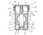
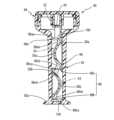
先ず、図1には、本発明に従うSCL用収納ケースの一例が、縦断面形態において概略的に示されている。そこにおいて、SCL用収納ケース10は、所定の液体が収容されることとなる、内周面が円形とされた有底円筒形状の容器本体12と、この容器本体12の上部開口部に着脱可能に取り付けられて、かかる容器本体12内部に密閉空間を形成するキャップ部材14と、このキャップ部材14の内側に取り付けられ、収納対象となるSCL24を保持するレンズホルダ16とを有している。そして、これら容器本体12とキャップ部材14とレンズホルダ16とは、何れも、ポリエチレン、ポリプロピレン、ポリスチレン、ポリカーボネート等の、従来からSCL用収容ケース材料として周知の合成樹脂を用いた、射出成形等の公知の成形操作によって、形成されている。First, FIG. 1 shows an example of an SCL storage case according to the present invention, in a vertical cross-sectional view. The
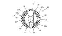
具体的には、容器本体12は、図1及び図2から明らかな如く、所定厚さの円筒状の筒壁部12aと、その下端部を閉塞する底部12bとから、構成されており、その筒壁部12aの上端開口部の外周部には、キャップ部材14が螺合せしめられる外側ネジ部12cが、設けられている。なお、ここでは、容器本体12の底部12bの中央部が、容器本体12内に突出せしめられて、円形の当接台座部18が設けられており、更に、この当接台座部18の中央部から筒壁部12a内に円錐体形状において突出する円錐形状部20が、一体的に形成されている。Specifically, as is clear from Figures 1 and 2, the
一方、キャップ部材14は、レンズホルダ16が固定的に取り付けられてなる形態において、用いられるようになっており、かかるレンズホルダ16を容器本体12の筒内に装入せしめてなる形態において、筒壁部12aの上部外周部に螺合せしめられるように構成されて、容器本体12に対して着脱可能に取り付けられるようになっている。即ち、キャップ部材14は、円盤状の天板部14aの外周部から所定高さ垂下する外周筒部14bを有し、この外周筒部14bの内周面に設けられた内側ネジ部14cが、容器本体12の上部開口部の外周部に設けられた外側ネジ部12cに螺合せしめられることによって、容器本体12の上部開口部が液密に閉塞せしめられるようになっている。また、かかるキャップ14の天板部14aの内面(下面)の中央部には、外周筒部14bと略同じ高さにおいて、嵌合筒部22が一体的に設けられている。そして、このキャップ14に設けられた嵌合筒部22に対して、後述するレンズホルダ16のホルダ基部が嵌合固定せしめられることにより、図示の如く、キャップ14の内側に、レンズホルダ16が垂下されてなる形態において、取り付けられるようになっているのである。On the other hand, the
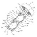
さらに、上記した容器本体12及びキャップ14と共に、SCL用収納ケース10を構成し、収納されるべきSCL24を保持するレンズホルダ16は、図1,図3及び図4(a),(b)に示されるように、キャップ14の内側に位置固定に保持されるホルダ基部26と、このホルダ基部26に連結されて、所定間隙を隔てて相対向するように下方に垂下する一対の板状のホルダ本体28,28と、それらホルダ本体28,28に一体的に設けられた、右眼用SCL24及び左眼用SCL24がそれぞれ載置されるドーム状のレンズ台座部30,30と、そのようなレンズ台座部30の上下に位置するホルダ本体28部位にそれぞれ設けられた上側壁部32a及び下側壁部32bから構成されるレンズ収容壁部32とを有している。なお、各ホルダ本体28の下側壁部32bよりも下方に位置する部位には、図4(a)から明らかな如く、対応するレンズ台座部30に載置されるべきSCL24が、右眼用(R)であるのか、或いは左眼用(L)であるのかを明確にするために、R又はLの符号が浮き彫り形態において形成されている。Furthermore, the
より詳細には、レンズホルダ16は、図1~図4から明らかなように、キャップ14の天板部14aの内面に設けられた嵌合筒部22に強制的に嵌入されて、位置固定に保持されるホルダ基部26を有しており、このホルダ基部26には、その下端から、水平方向に所定距離を隔てて、互いに平行に下方に垂下するように延びる、所定幅の板状のホルダ本体28,28が設けられている。そして、それら二つのホルダ本体28,28の垂下方向の中間部位には、SCL24が載置されるドーム状乃至は球状のレンズ台座部30,30が、それぞれの板面から互いに反対方向に(外方に)突出する形態において、一体的に設けられて、図1や図2に示されるように、容器本体12の筒壁部12aの円形の内周面との間に、SCL24を収容し得る隙間が形成されるようになっている。なお、それらドーム状レンズ台座部30,30は、何れも、載置されるSCL24のベースカーブ(後面カーブ)よりも小さな曲率半径の表面を有し、また通液孔やスリット等が存在しない、凹凸のない平滑な湾曲凸面とされた表面を有するように、構成されており、これによって、載置されるSCL24に対して、より大きな表面張力乃至は付着力が発生せしめられ得るようになっている。More specifically, as is clear from Figures 1 to 4, the
また、それらドーム状レンズ台座部30,30の上側及び下側に位置するホルダ本体28,28の部位には、それぞれ、図3や図4に示されるように、平面形態において円弧形状を呈する上側壁部32a及び下側壁部32bが、レンズ台座部30よりも高い高さにおいて設けられて、それら上側壁部32aと下側壁部32bとによって、レンズ収容壁部32が構成されている。なお、かかるレンズ収容壁部32を構成する上側壁部32a及び下側壁部32bは、図3より明らかな如く、それぞれ、その円弧形状の中央部位から両端部に向かって漸次高さが低くなるように形成されて、ホルダ本体28の両側部に至るようになっているのであり、これによって、両側部が解放されてなる構造のレンズ収容壁部32を構成している。即ち、上側壁部32aと下側壁部32bとは、それらが設けられている板状のホルダ本体28の板面に垂直な方向から見ても、また、かかる板面に平行な方向から見ても、円弧形状を呈する形態において、設けられているのである。そして、このようなレンズ収容壁部32(上側壁部32a+下側壁部32b)が、レンズ台座部30と容器本体12の筒壁部12aの内周面との間において、SCL24が収容される空間を形成しているのである。3 and 4, upper and
従って、そのようなレンズ収容空間内に存在するSCL24が、そこから抜け出さないように、容器本体12の筒壁部12aの内周面と、レンズ収容壁部32の上端部やホルダ本体28の両側部との間の間隙は、図1や図2に示されるように、狭い間隙とされている必要があり、一般に2mm未満、好ましくは1.5mm以下、より好ましくは0.3mm~1.0mm程度の間隙として、構成されることとなる。また、レンズ収容壁部32の外方に解放された両側部の長さ、換言すれば、上側壁部32aと下側壁部32bの対応する端部間の距離にあっても、SCL24の側方への抜け出しを阻止するために、通常、SCL24の直径よりも短い長さとなるように、設定されているのである。Therefore, in order to prevent the
さらに、レンズ収容壁部32を構成する上側壁部32aと下側壁部32bにおいては、図1、図3、図4等から明らかなように、それぞれの円弧形状の中央部に、SCL24が抜け出さない大きさにおいて、換言すれば、SCL24の直径よりも小さな幅において、U字形状の切欠き34が設けられている。このような切欠き34が、レンズ収容壁部32の上下に位置する上側壁部32a及び下側壁部32bに存在していることにより、レンズホルダ16を容器本体12内の収容液体中に浸漬したり、或いは、それより引き上げたりしたときに、この切欠き34を通じて、気体(空気)や収容液体が、SCL24の収容空間から外部に排出せしめられ得るようになっており、これによって、レンズ台座部30とレンズ収容壁部32と容器本体12の筒壁部12aの内周面(内壁面)との間に形成されるレンズ収容空間内に気体や液体がトラップされて、惹起されるトラブルが、効果的に回避され得るようになっているのである。Furthermore, in the
そして、かくの如き構成のレンズホルダ16は、キャップ14に固定的に組み付けられて、図3や図4に示される如き形態とされた後、その両側のレンズ台座部30,30に右眼用SCL24及び左眼用SCL24がそれぞれ載置、保持せしめられた状態において、容器本体12内に収容されている液体中に浸漬せしめられた後、容器本体12の筒壁部12aの外側ネジ部12cにキャップ14の内側ネジ部14cが螺合せしめられて、液密状態が確保されてなる形態下において、SCL24の保存が行われることとなる。なお、その際、レンズホルダ16の二つのホルダ本体28,28は、ここでは、図1に示される如く、それらの下端部が、それぞれ、容器本体12の底部12bに突設形成されてなる当接台座部18の上面に当接することによって、ホルダ本体28,28の下端が支持されるようになっていると共に、それらホルダ本体28,28の下端部間に、円錐形状部20が嵌入されることにより、それらホルダ本体28,28の下端部間の距離が一定に維持され、互いに平行となるように保持されることによって、それぞれのレンズ台座部30とレンズ収容壁部32と容器本体12の筒壁部12aの内周面とによって形成されるレンズ収容空間が、所定の大きさに規制され得るようになっている。The
ところで、本発明に従うSCL用収納ケースは、上記で検討した図1~図4に示される実施形態の他にも、各種の変形を加えることが可能であり、図5~図7には、左眼用及び右眼用の二つのSCL24,24を保持するレンズホルダ16の製造の容易な一つの変形例が、示されている。Incidentally, the storage case for SCLs according to the present invention can be modified in various ways in addition to the embodiment shown in Figures 1 to 4 discussed above, and Figures 5 to 7 show one modified example of an easy-to-
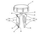
すなわち、図5には、レンズホルダ16が展開されてなる形態において示されており、そのような展開形態においては、アンダーカット部位が殆ど存在しないところから、それを、公知の射出成形操作を採用することによって、樹脂の一体成形品として、容易に形成することが出来ることとなり、以て、製造コストの低減に有利に寄与し得るようになっている。そこにおいて、二つのホルダ本体28,28が、ホルダ基部26の両側に、それぞれ位置せしめられてなる形態において、レンズホルダ16が一体的に形成されているのである。また、そこでは、ホルダ基部26とホルダ本体28との連結部が、図5(b)に示されるように、薄肉のヒンジ部36とされて、このヒンジ部36における屈曲にて回動可能とされていることにより、それら二つのホルダ本体28,28が、互いに平行に対向位置せしめられ得るようになっているのである。なお、二つのホルダ本体28,28の対向面の一方の下端部側には、長円形状の筒状部38が設けられている一方、他方の対向面の下端部側には、長円形状のピン部40が所定高さで設けられており、かかる筒状部38の長円形状の筒内に、ピン部40が差し込まれることによって、二つのホルダ本体28,28の間隔が互いに平行となるように保持され得るようになっている。また、図5(a)に示されるように、二つのホルダ本体28,28の下端側に位置する部位には、L(左眼用)やR(右眼用)の文字が浮き彫り形態において形成されており、それぞれの文字の付されたホルダ本体28に設けられているレンズ台座部30に載置されるべきSCL24の種類が指定されて、装用者がSCL24の装着に際して、対象となる眼を間違わないようになっている。That is, in Fig. 5, the
そして、図5に展開状態で示されているレンズホルダ16は、図6に示される如く、ホルダ基部26の矩形のプレート部26aの対応する2辺にそれぞれ連結されたホルダ本体28,28を、それぞれの連結部に形成されたヒンジ部36,36において屈曲させて、回動せしめることによって、互いに平行となるように相対向して位置せしめると共に、一方のホルダ本体28に設けられた長円形状のピン部40を他方のホルダ本体28に設けられた筒状部38の長円形状の筒内に嵌入せしめることによって(図7参照)、二つのホルダ本体28,28が互いに平行となるように固定、保持せしめることにより、組み立てられることとなるのである。このように、筒状部38へのピン部40の嵌入によって、二つのホルダ本体28,28の間隔が固定されることにより、レンズホルダ16が容器本体12内に装入せしめられたり、或いは、引き上げられたりした際に、容器本体12の筒壁部12aの内面や開口部にホルダ本体28が当接して、レンズ台座部30と筒壁部12aの内壁面との間の距離が変化せしめられたときに、SCL24が脱落したりする問題が有利に回避され得ることとなる。The
また、かくの如きレンズホルダ16は、ホルダ基部26の上方に突出するピン部26bにおいて、キャップ14の嵌合筒部22内に嵌入固定せしめられてなる形態において、二つのレンズ台座部30,30に対して、左眼用及び右眼用の二つのSCL24,24がそれぞれ載置、保持された後、図8に示される如く、容器本体12内に収容された所定の液体42中に浸漬されてなる形態において、容器本体12の開口部に、キャップ14が螺合により取り付けられることによって、装用者から取り外された左眼用や右眼用のSCL24が、SCL用収納ケース10内に収納、保持された状態において、所望の消毒処理や洗浄処理が施されるようになるのである。なお、容器本体12内に収容される液体42には、浸漬されるSCL24に対して、洗浄、消毒、表面濡れ性の改善等の作用を為す、従来と同様な液体が、そのまま、用いられることとなる。In addition, such a
このように、上述の如き構成のSCL用収納ケース10にあっては、レンズホルダ16におけるSCL24が載置されるレンズ台座部30を覆蓋する蓋部材は、何等設けられておらず、レンズ台座部30とレンズ収容壁部32(上側壁部32a+下側壁部32b)と容器本体12における筒壁部12aの内壁面とによって規定されるレンズ収容空間内に、SCL24が収容、保持されることとなるところから、レンズホルダ16におけるレンズ台座部30に対するSCL24の載置や、そこからのSCL24の取出しに際して、蓋部材を開閉させる作業が全く必要でなくなり、それによって、レンズホルダ16に対するSCL24の収納や取出しの操作性が、効果的に向上せしめられ得ることとなることに加えて、蓋部材の開閉によるSCL24の挟込みの問題も、全く惹起されることがないところから、SCL24が損傷を受けたり、破損したりする恐れも、全く解消され得ることとなったのである。In this way, in the
しかも、レンズホルダ16には、蓋部材が存在するものではないところから、蓋部材の開閉操作によって惹起される、レンズホルダ16に付着する液体42の飛散が生じるような恐れもないことに加えて、容器本体12中の収容液体42から、レンズホルダ16が引き上げられた際にも、蓋部材に残留する液体の液垂れの問題が惹起されることはなく、特に、レンズ収容壁部32を構成する上側壁部32aや下側壁部32bには、その円弧形状の中央部位に切欠き34が形成されているところから、かかるレンズ収容壁部32に残留する液体42も、可及的に低減され得ることとなり、これによって、レンズホルダ16が容器本体12内から引き上げられて、外部に取り出された際に、レンズホルダ16からの液垂れも、可及的に抑制され得て、SCL24の取扱い作業性が有利に向上せしめられ得ることとなるのである。なお、それら上側壁部32aや下側壁部32bに設けられた切欠き34は、また、レンズホルダ16が容器本体12中の収容液体42内に浸漬されるに際しても、レンズ収容空間内の空気の如き気体を、外部に効果的に排出せしめる効果を発揮し、これによって、残留気体によるSCL24の収容状態への悪影響を回避することが可能となる。Moreover, since there is no lid member on the
また、レンズホルダ16には、蓋部材を設ける必要がないところから、そのような蓋部材の開閉のための回動機構や、蓋部材の嵌合部も設ける必要がなく、これにより、レンズホルダ16自体の構造も簡略化することが出来、以て、シンプルな構造のレンズホルダとすることが可能となると共に、容器本体12の筒壁部12aの内壁面(内周面)が、円筒形状となっているところから、キャップ14の螺合時におけるレンズホルダ16の方向性(回転位置)を何等顧慮する必要もないという特徴も発揮され得るのである。In addition, since there is no need to provide a lid member for the
さらに、例示の実施形態の如く、右眼用や左眼用の二つのSCL24の保持のために、レンズ台座部30を容器本体12の筒壁部12aの深さ方向に配列せしめる構造とは異なり、かかる深さ方向に直角な方向に二つのレンズ台座部30,30が対向配置されてなる構造を採用することによって、左眼用及び右眼用のSCL24の収納場所の識別が容易となることに加えて、容器本体12内への液体42の充填量の不足によって、一方のSCL24が浸漬されないという問題が惹起されるようなことも、有利に回避され得ることとなるのである。Furthermore, unlike the structure in which the
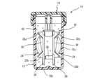
ところで、上述した実施形態に係るSCL用収納ケース10においては、容器本体12が、横断面が円形の内周面を有する有底円筒形状を呈するものであったが、本発明においては、図9以降に示される実施形態の如く、横断面が矩形の内周面を有する有底角筒形状を呈する容器本体を用いることも可能である。In the
具体的には、先ず、図9~図11に示される本発明の他の一つの実施形態において、SCL用収納ケース50は、矩形の有底角筒形状を呈する容器本体52と、その上部に螺合せしめられるキャップ部材54とを有している。そして、かかるキャップ部材54の螺合のために、容器本体52の上部は、円形の外周部を与える形状とされている。また、かかる容器本体52の内周面は、図10(a)及び(b)に示される断面図から明らかなように、矩形の横断面形状を呈しており、そのような矩形の横断面形状の内部に、レンズホルダ56が収容せしめられるようになっているのである。なお、以下の実施形態に係るSCL用収納ケースの構成の説明において、先の実施形態に係るSCL用収納ケース10と同様な構造の部分には、同一符号を付すこととして、その構造についての詳細な説明は、省略することとする。Specifically, in another embodiment of the present invention shown in Figs. 9 to 11, the
そして、上記のSCL用収納ケース50において、キャップ部材54に対するレンズホルダ56の取付けは、キャップ部材54の内面に設けた嵌合筒部22に対して、レンズホルダ56のホルダ基部26を嵌合せしめることによって、行なわれることとなるのであるが、そこでは、特開2018-68871号公報にも詳述されている如く、嵌合筒部22の内面に設けた適数本のリング状凹所と、ホルダ基部26の筒状部の外周面に設けた適数本のリング状凸部との嵌合によって、レンズホルダ56が、キャップ部材54に対して位置固定に保持され得るようになっていると共に、嵌合筒部22の軸回りに、ホルダ基部26が自由に回動可能に保持されるようになっている。In the above-mentioned
また、レンズホルダ56は、図5及び図6に示されるレンズホルダ16と同様に、ホルダ基部26と、その両側部から平行に垂下するように折曲せしめられる二つのホルダ本体28,28とを一体的に有する一体成形品として、形成されたものであるが、そこでは、図10(a)から明らかなように、二つのホルダ本体28,28は、その上部と下部において、それぞれ、その一方に設けられた筒状部38と他方に設けられたピン部40との嵌合によって、相互の間隔が一定となるようにして、固定せしめられている。このような筒状部38とピン部40の嵌合構造が、二つのホルダ本体28,28の上部と下部において設けられていることにより、それら二つのホルダ本体28,28の関係位置の固定が、より有効に行なわれ得るようになっているのである。Like the
さらに、それら二つのホルダ本体28,28のそれぞれに設けられたドーム状のレンズ台座部30を挟んで、その上側と下側に位置するように、上側壁部58aと下側壁部58bとが、ホルダ本体28に対して一体的に設けられて、それら上側壁部58aと下側壁部58bとによって、レンズ収容壁部58が構成されている。そして、それら上側及び下側壁部58a,58bと容器本体52の内周面とレンズ台座部30との間に、SCL24を収容するレンズ収容空間が形成されるようになっているのである。なお、レンズ収容壁部58を構成する上側壁部58aと下側壁部58bは、それらの頂部とそれに対応する容器本体52の内周面との間の隙間から、前記した収容空間内のSCLが抜け出さない高さにおいて、立設されるようになっている。Furthermore, the
そして、図11から明らかな如く、上側壁部58aと下側壁部58bは、何れも、水平方向に延びる所定高さの水平壁部58aa,58baと、そのような水平壁部58aa,58baの両側部から上下方向にそれぞれ所定長さで延びる、水平壁部58aa,58baの高さよりも低い高さの側壁部58ab,58ab;58bb,58bbとから構成されていると共に、上側壁部58aの側壁部58abと下側壁部58bの側壁部58bbとの間は、壁部の存在しない開放部となっている。そして、それら上側壁部58aや下側壁部58bにおける水平壁部58aa,58baの中央部が大きく矩形に切り欠かれて、それぞれ、切欠き部60が形成されている。As is clear from FIG. 11, the
従って、図11に示される如きレンズホルダ56が、容器本体52の矩形の断面形状を有する内部に収容されると、図10(b)に示されるように、SCL24が通り抜け得ない間隙が、上側壁部58aや下側壁部58bと容器本体52の矩形の内周面の対応するものとの間において、形成されることとなるのである。そして、そのような形態において、レンズ台座部30と上下の壁部58a,58bと容器本体52の内周面との間に、SCL24を収容し得る空間が形成されることとなり、それ故に、そのような空間内に収容されたSCL24は、そこに、効果的に収容、保持されて、外部に抜け出すことがないところから、従来の如く、レンズ台座部を覆蓋する蓋部材を設ける必要がなく、これによって、レンズホルダ56の構造を効果的に簡略化せしめ得ると共に、SCL24の収容・取出し操作をより容易とすることが出来るのである。When the
また、図12~図14には、本発明に従うSCL用収納ケースの異なる他の例が示されている。そこにおいて、SCL用収納ケース70は、容器本体72とキャップ部材74とレンズホルダ76とを有し、そして、容器本体72やキャップ部材74は、先の実施形態に係るSCL用収納ケース50と同様な構造とされている。なお、容器本体72は、ここでは、その下端部に、その高さ方向中央部の横断面形状よりも大なる外形を有する長円形状の支持部72aが一体的に形成されていると共に、その内周面が横長矩形の横断面形状を呈する、高さの高い矩形角筒形状を有するものとして、構成されている。Figures 12 to 14 show other examples of storage cases for SCL according to the present invention. In these, storage case for
さらに、図13(a)や図14から明らかなように、レンズホルダ76には、その長手方向(上下方向)に、二つのレンズ台座部30a,30bが、所定距離を隔てて直列に配設されているのである。また、そのように連設された二つのレンズ台座部30a,30bのうちの上側のレンズ台座部30aの上側に位置するように、上側壁部78aが設けられており、更に下側のレンズ台座部30bの下側に位置するように、下側壁部78bが設けられていると共に、それら二つのレンズ台座部30a,30bの間に位置するように、中間壁部78cが、レンズホルダ76に対して一体的に設けられている。そして、それら上側壁部78aと中間壁部78cによって、上側のレンズ台座部30aに対するレンズ収容壁部78が構成されている一方、中間壁部78cと下側壁部78bとによって、下側のレンズ台座部30bに対するレンズ収容壁部78が構成されているのである。要するに、ここでは、中間壁部78cは、上側レンズ台座部30aの下側壁部と、下側レンズ台座部30bの上側壁部を兼ねる構成となっているのである。Furthermore, as is clear from Fig. 13(a) and Fig. 14, the
そして、図14から明らかな如く、上側壁部78a、下側壁部78b及び中間壁部78cは、何れも、水平方向に延びる一定高さの水平壁部78aa,78ba,78caを有していると共に、水平壁部78aaや78baおいては、上下方向において、互いに対向する方向に高さの低い側壁部78ab78bbが、所定長さにおいて一体的に形成されている一方、中間壁部78cには、その両側から上下方向に延びる、水平壁部78caよりも高さの低い側壁部78cb,78cbが、それぞれ、上下方向に一体的に設けられているのである。As is clear from FIG. 14, the
加えて、それら上側壁部78a、下側壁部78b及び中間壁部78cには、それぞれの水平壁部78aa,78ba,78caの中央部に位置するように、切欠き80が設けられると共に、両側壁部78ab,78ab;78bb,78bb;78cb,78cbに近接して、それぞれの水平壁部78aa,78ba,78caを貫通し且つホルダ本体28を貫通するL字形態において、通孔82が、形成されている。In addition, the
従って、図14に示される如き、レンズホルダ76の取り付けられたキャップ部材74において、レンズホルダ76が容器本体72の矩形形状の内部に挿入される一方、キャップ部材74が、その回動によって、容器本体72の上部に螺合せしめられると、図13(a)及び(b)に示されるように、SCL24が抜け出し得ない隙間が、容器本体72の内周面と上側壁部78a、下側壁部78b、中間壁部78cとの間に形成されてなる形態において、容器本体72の内面と、上側壁部78a、中間壁部78c又は中間壁部78c、下側壁部78bと、レンズ台座部30a又は30bとの間に、SCL24のレンズ収容空間が、ホルダ本体28の長手方向に、換言すれば容器本体72の高さ方向に直列した形態において、形成されることとなるのである。As shown in FIG. 14, when the
かくの如く、SCL24のレンズ収容空間の形成に際しては、レンズホルダ76に対して、従来の如くレンズ台座部30a/30bを覆蓋するような蓋部材を用いる必要がないところから、それら二つのレンズ台座部30a,30bに対して、左眼用及び右眼用のSCL24,24を、そのまま、それぞれのレンズ台座部30a,30b上に載置せしめてなる形態において、容器本体72内に挿入したり、或いは容器本体72から取り出すことが出来ることとなるのである。As described above, when forming the lens storage space for the
さらに、図15~図17には、図14に示されるレンズホルダ76の変形例を用いた、本発明に係るSCL用収納ケースの異なる他の一例が、示されている。そこにおいて、SCL用収納ケース90は、図12~図14に示されるSCL用収納ケース70と同様な構造の容器本体92とキャップ部材94とを有していると共に、レンズホルダ96は、図15~図17より明らかな如く、直列に配設される2つのレンズ台座部30a,30bが、互いに反対方向に凸なる形状において配設されているところに、大きな特徴を有している。即ち、かかるレンズホルダ96のホルダ本体28は、上側のレンズ台座部30aが配設された上側ホルダ本体28aと、下側のレンズ台座部30bが配設された下側ホルダ本体28bとから構成され、それら上側及び下側ホルダ本体28a,28bが、中間壁部98cの高さにて与えられる段差部をもって、クランク状に連設されてなる構造とされているのである。Furthermore, Figures 15 to 17 show another example of a storage case for SCL according to the present invention, which uses a modified version of the
そして、上側のレンズ台座部30aの上側に位置するように、上側壁部98aが、上側ホルダ本体28aに対して一体的に設けられている一方、下側のレンズ台座部30bの下側に位置するように、下側壁部98bが、下側ホルダ本体28bに対して一体的に設けられているのである。また、それら上側壁部98aと下側壁部98bとは、図12~図14に示される実施形態と同様に、切欠き100と通孔102が形成されている。更に、中間壁部98cには、図16や図17から明らかなように、中間壁部98cを貫通し、上側ホルダ本体28a及び下側ホルダ本体28bに至る二つの通孔102が、両側の側壁部98cb側に偏位して、設けられている。The
かくして、かくの如き構成のレンズホルダ96を有するキャップ部材94において、レンズホルダ96が、図17に示される如く、容器本体92内に差し込まれる一方、キャップ部材94が容器本体92の上部に螺合せしめられることによって、図15に示されるように、容器本体92の内面と、上側壁部98a、中間壁部98cと、上側レンズ台座部30aとの間、及び容器本体92の内面と、中間壁部98c、下側壁部98bと、下側レンズ台座部30bとの間に、それぞれ、SCL24の収容空間が形成されることとなるのであり、これによって、それらレンズ台座部30a,30bを覆蓋する蓋部材を用いることなく、左眼用及び右眼用のSCL24,24を、SCL用収納ケース90内にそれぞれ収容し、また、それより、二つのSCL24,24を取り出すことが容易に出来ることとなるのである。Thus, in the
このように、図面に示される本発明の実施形態に係る各種のSCL用の収納ケース(10,50,70,90)は、装用者の眼から取り外されたSCL24を、次回の装用機会まで、保持乃至は保存し得る容器として、数々の有用な特徴を発揮するものであるが、そのようなSCL用収納ケース(10等)は、あくまでも、本発明の代表的な実施形態としての例示に過ぎないものであって、本発明は、そのような実施形態に係る具体的な記述によって、何等限定的に解釈されるものでないことが、理解されるべきである。As described above, the various storage cases for SCLs (10, 50, 70, 90) according to the embodiments of the present invention shown in the drawings exhibit a number of useful features as containers capable of holding or preserving the
例えば、上記の実施形態においては、左眼用及び右眼用の二つのSCL24,24を収容すべく、レンズホルダ16が二つのホルダ本体28,28;28a,28bを有し、そこに、二つのレンズ台座部30,30;30a,30bが設けられてなる構造とされているのであるが、勿論、一つのSCL24の収容を目的として、レンズホルダ16が一つのホルダ本体28を有し、そこに、一つのレンズ台座部30が設けられてなる構造とされていても、何等差し支えない。For example, in the above embodiment, the
また、上側壁部32a,58a,78a,98a、下側壁部32b,58b,78b,98b及び中間壁部78c,98cには、切欠き34,60,80,100や通孔82,102が設けられているが、それら切欠きや通孔は、任意の形状において形成され得るものであることは勿論、その何れか一方が、又はその両方が、それぞれの壁部に設けられるようにすることが出来、更に、それら切欠きや通孔の数としても、各壁部において、一つのみならず、複数の配設も可能であることは、言うまでもないところである。In addition, the
さらに、例示の容器本体52,72,92における内周面は、何れも、横断面が矩形形状を呈するものであるが、五角形、六角形、八角形等の多角形形状を呈するものであっても、何等差し支えない。そして、そのような多角形形状の内周面に対応して、それとの間に、SCLが抜け出さない間隙が形成されるように、上側壁部58a,78a,98aや下側壁部58b,78b,98bの高さが適宜に設定され、また中間壁部78c,98cの高さが適宜に設定されることとなる。Furthermore, the inner peripheral surfaces of the illustrated
更にまた、容器本体12,52,72,92の開口部に対するキャップ14,54,74,94の取付構造にあっても、例示の如き螺合方式の他、容器本体12等の開口部に着脱可能に取り付けられて、かかる容器本体12等の内部に密閉空間を形成し得る公知の取付構造、例えば、スナップ嵌合方式等も、適宜に採用可能である。Furthermore, in terms of the attachment structure of the
また、例示の実施形態では、対向する二つのホルダ本体28,28の下端部同士を相互に連結し、それらの間の間隔を維持する連結手段として、筒状部38とそれに嵌入せしめられるピン部40との組合せからなる構成が採用されているが、これに代えて、公知の各種の連結構造を採用することが可能である。例えば、一方のホルダ本体28から延びるフック部材にて、他方のホルダ本体28を係止する構造や、二つのホルダ本体28,28間の間隔を保持する部材を、それらホルダ本体28,28に接着乃至は溶着等により固設する方式等も、適宜に採用可能である。In the illustrated embodiment, the connecting means for connecting the lower ends of the two opposing
加えて、本発明に従うSCL用収納ケース(10)は、ホルダ本体28の下端部に白金触媒部材を取り付け、レンズホルダ(16)と共に、容器本体(12)内の過酸化水素溶液(42)中に浸漬して、過酸化水素による殺菌を進行せしめるようにした、過酸化水素消毒用のレンズケースとしても、使用可能となるものである。In addition, the SCL storage case (10) according to the present invention can also be used as a lens case for hydrogen peroxide disinfection by attaching a platinum catalyst member to the lower end of the
その他、一々列挙はしないが、本発明は、当業者の知識に基づいて、種々なる変更、修正、改良等を加えた態様において実施され得るものであり、更に、そのような実施の態様が、本発明の趣旨を逸脱しない限りにおいて、何れも、本発明の範疇に属するものであることは、言うまでもないところである。Although we will not list them all here, the present invention can be embodied in various ways with changes, modifications, improvements, etc. based on the knowledge of those skilled in the art, and it goes without saying that all such embodiments are within the scope of the present invention as long as they do not deviate from the spirit of the present invention.
10,50,70,90 SCL用収納ケース
12,52,72,92 容器本体
12a 筒壁部 12b 底部
12c ネジ部 14,54,74,94 キャップ部材
14a 天板部 14b 外周筒部
14c 内側ネジ部 16,56,76 レンズホルダ
18 当接台座部 20 円錐形状部
22 嵌合筒部 24 SCL
26 ホルダ基部 26a プレート部
26b ピン部 28 ホルダ本体
30,30a,30b レンズ台座部
32,58,78 レンズ収容壁部
32a,58a,78a,98a 上側壁部
32b,58b,78b,98b 下側壁部
34,60,80,100 切欠き
36 ヒンジ部 38 筒状部
40 ピン部 42 液体
72a 支持部 78c,98c 中間壁部
82,102 通孔
10, 50, 70, 90
26
Claims (13)
Translated fromJapanese前記レンズホルダが、前記キャップ部材の内側に位置固定に保持されるホルダ基部と、該ホルダ基部に連結されて、下方に垂下するように延びる所定幅の板状のホルダ本体と、かかるホルダ本体に対して、板面から突出せる形態において一体的に設けられ、前記容器本体の内周面との間に前記ソフトコンタクトレンズを収容し得る隙間を形成する、該ソフトコンタクトレンズが載置されるドーム状乃至は球状のレンズ台座部と、該レンズ台座部の上側及び下側に位置する前記ホルダ本体の部位にそれぞれ設けられた上側壁部及び下側壁部から構成され、両側部が解放されてなる構造を呈する、該ソフトコンタクトレンズを挟んで保持することのないレンズ収容壁部とを有し、
且つ該レンズ収容壁部の上側及び下側壁部が、前記容器本体の内周面との間の隙間から前記収容空間内のソフトコンタクトレンズが抜け出さない高さにおいて、立設されていると共に、
前記ソフトコンタクトレンズの収容空間が、蓋部材を用いた覆蓋によることなく、前記レンズ台座部と該レンズ台座部に対向する前記容器本体の内周面と前記レンズ収容壁部とによって画成されていることを特徴とするソフトコンタクトレンズ用収納ケース。 a storage case comprising a bottomed cylindrical container body for storing a predetermined liquid, a cap member removably attached to an upper opening of the container body and capable of forming an enclosed space inside the container body, and a lens holder attached to the inside of the cap member, holding a soft contact lens to be stored, inserted through the upper opening of the container body, and immersed in the stored liquid in the container body,
the lens holder comprises a holder base that is held in a fixed position inside the cap member, a plate-like holder body of a predetermined width that is connected to the holder base and extends downward, a dome-shaped or spherical lens pedestal on which the soft contact lens is placed that is integrally provided with the holder body in a form that protrudes from the plate surface and forms a gap between the holder body and the inner peripheral surface of the container body in which the soft contact lens can be accommodated, and a lens accommodation wallthat does not sandwich and hold the soft contact lens and is composed of upper and lower wall portions provided respectively on portions of the holder body located above and below the lens pedestal, and has a structure in which both sides are open,
The upper and lower walls of the lens housing wall are erected at a height such that the soft contact lens in the housing space does not slip out through a gap between the upper and lower walls and the inner peripheral surface of the container body.
A storage case for soft contact lenses, characterized in that the storage space for the soft contact lens is defined by the lens base, the inner surface of the container body facing the lens base, and the lens storage wall, without being covered with a lid member.
前記レンズホルダが、前記キャップ部材の内側に位置固定に保持されるホルダ基部と、該ホルダ基部に連結されて、下方に垂下するように延びる所定幅の板状のホルダ本体と、かかるホルダ本体に対して、板面から突出せる形態において一体的に設けられ、前記容器本体の内周面との間に前記ソフトコンタクトレンズを収容し得る隙間を形成する、該ソフトコンタクトレンズが載置されるドーム状乃至は球状のレンズ台座部と、該レンズ台座部の上側及び下側に位置する前記ホルダ本体の部位にそれぞれ設けられた上側壁部及び下側壁部から構成され、両側部が解放されてなる構造を呈する、該ソフトコンタクトレンズを挟んで保持することのないレンズ収容壁部とを有し、
且つ該レンズ収容壁部の上側及び下側壁部が、前記容器本体の内周面との間の隙間が2mm未満となる高さにおいてそれぞれ立設されて、かかる隙間から、前記収容空間内のソフトコンタクトレンズが抜け出さないように構成されていると共に、
前記ソフトコンタクトレンズの収容空間が、蓋部材を用いた覆蓋によることなく、前記レンズ台座部と該レンズ台座部に対向する前記容器本体の内周面と前記レンズ収容壁部とによって画成されていることを特徴とするソフトコンタクトレンズ用収納ケース。 a storage case comprising a bottomed cylindrical container body for storing a predetermined liquid, a cap member removably attached to an upper opening of the container body and capable of forming an enclosed space inside the container body, and a lens holder attached to the inside of the cap member, holding a soft contact lens to be stored, inserted through the upper opening of the container body, and immersed in the stored liquid in the container body,
the lens holder comprises a holder base that is held in a fixed position inside the cap member, a plate-like holder body of a predetermined width that is connected to the holder base and extends downward, a dome-shaped or spherical lens pedestal on which the soft contact lens is placed that is integrally provided with the holder body in a form that protrudes from the plate surface and forms a gap between the holder body and the inner peripheral surface of the container body in which the soft contact lens can be accommodated, and a lens accommodation wallthat does not sandwich and hold the soft contact lens and is composed of upper and lower wall portions provided respectively on portions of the holder body located above and below the lens pedestal, and has a structure in which both sides are open,
The upper and lower walls of the lens housing wall are erected at a height such that the gap between the wall and the inner peripheral surface of the container body is less than 2 mm, so that the soft contact lens in the housing space does not slip out through the gap.
A storage case for soft contact lenses, characterized in that the storage space for the soft contact lens is defined by the lens base, the inner surface of the container body facing the lens base, and the lens storage wall, without being covered with a lid member.
A storage case for soft contact lenses as described in claim 12, characterized in that the connecting means is composed of a cylindrical portion provided at one of the lower ends of the two holder bodies and a pin portion provided at theother of the lower ends, and is configured so that the distance between the two holder bodies can be maintained by inserting the pin portion into the cylindrical portion.
Priority Applications (2)
| Application Number | Priority Date | Filing Date | Title |
|---|---|---|---|
| JP2020175512AJP7633793B2 (en) | 2020-10-19 | 2020-10-19 | Soft contact lens storage case |
| JP2024172737AJP2024174160A (en) | 2020-10-19 | 2024-10-01 | Soft contact lens storage case |
Applications Claiming Priority (1)
| Application Number | Priority Date | Filing Date | Title |
|---|---|---|---|
| JP2020175512AJP7633793B2 (en) | 2020-10-19 | 2020-10-19 | Soft contact lens storage case |
Related Child Applications (1)
| Application Number | Title | Priority Date | Filing Date |
|---|---|---|---|
| JP2024172737ADivisionJP2024174160A (en) | 2020-10-19 | 2024-10-01 | Soft contact lens storage case |
Publications (2)
| Publication Number | Publication Date |
|---|---|
| JP2022066908A JP2022066908A (en) | 2022-05-02 |
| JP7633793B2true JP7633793B2 (en) | 2025-02-20 |
Family
ID=81389808
Family Applications (2)
| Application Number | Title | Priority Date | Filing Date |
|---|---|---|---|
| JP2020175512AActiveJP7633793B2 (en) | 2020-10-19 | 2020-10-19 | Soft contact lens storage case |
| JP2024172737APendingJP2024174160A (en) | 2020-10-19 | 2024-10-01 | Soft contact lens storage case |
Family Applications After (1)
| Application Number | Title | Priority Date | Filing Date |
|---|---|---|---|
| JP2024172737APendingJP2024174160A (en) | 2020-10-19 | 2024-10-01 | Soft contact lens storage case |
Country Status (1)
| Country | Link |
|---|---|
| JP (2) | JP7633793B2 (en) |
Families Citing this family (1)
| Publication number | Priority date | Publication date | Assignee | Title |
|---|---|---|---|---|
| JP7301425B2 (en)* | 2019-05-24 | 2023-07-03 | 株式会社大一商会 | game machine |
Citations (4)
| Publication number | Priority date | Publication date | Assignee | Title |
|---|---|---|---|---|
| WO2011004438A1 (en) | 2009-07-10 | 2011-01-13 | 株式会社メニコン | Catalyst for sterilizing contact lenses and apparatus and method for sterilizing contact lenses using same |
| WO2012111038A1 (en) | 2011-02-14 | 2012-08-23 | 株式会社メニコン | Contact lens case |
| WO2012165209A1 (en) | 2011-05-31 | 2012-12-06 | 株式会社メニコンネクト | Contact lens holder |
| JP2018068871A (en) | 2016-11-02 | 2018-05-10 | 株式会社トーメーポート | Storage case for soft contact lens |
Family Cites Families (3)
| Publication number | Priority date | Publication date | Assignee | Title |
|---|---|---|---|---|
| US4807750A (en)* | 1987-10-28 | 1989-02-28 | Ryder International Corporation | Latching structure for contact lens holder |
| JPH02112116U (en)* | 1989-02-28 | 1990-09-07 | ||
| JPH05155A (en)* | 1990-08-09 | 1993-01-08 | Tome Sangyo Kk | Contact lens processing case and processing method of contact lens using the same |
- 2020
- 2020-10-19JPJP2020175512Apatent/JP7633793B2/enactiveActive
- 2024
- 2024-10-01JPJP2024172737Apatent/JP2024174160A/enactivePending
Patent Citations (4)
| Publication number | Priority date | Publication date | Assignee | Title |
|---|---|---|---|---|
| WO2011004438A1 (en) | 2009-07-10 | 2011-01-13 | 株式会社メニコン | Catalyst for sterilizing contact lenses and apparatus and method for sterilizing contact lenses using same |
| WO2012111038A1 (en) | 2011-02-14 | 2012-08-23 | 株式会社メニコン | Contact lens case |
| WO2012165209A1 (en) | 2011-05-31 | 2012-12-06 | 株式会社メニコンネクト | Contact lens holder |
| JP2018068871A (en) | 2016-11-02 | 2018-05-10 | 株式会社トーメーポート | Storage case for soft contact lens |
Also Published As
| Publication number | Publication date |
|---|---|
| JP2022066908A (en) | 2022-05-02 |
| JP2024174160A (en) | 2024-12-13 |
Similar Documents
| Publication | Publication Date | Title |
|---|---|---|
| JP4949029B2 (en) | Contact lens care system | |
| JP2024174160A (en) | Soft contact lens storage case | |
| AU748922B2 (en) | Container | |
| KR101693335B1 (en) | Container for dental implant | |
| EP0389418B1 (en) | Contact lens holding unit with invertible lens holding baskets | |
| CN1128639C (en) | Disinfection apparatus | |
| JP6055418B2 (en) | Pressure relief container for sterilization and storage of contact lenses and method of treating contact lenses | |
| JPH06205706A (en) | Contact lens case | |
| AU618389B2 (en) | Contact lens disinfection unit | |
| EP0529066B1 (en) | Contact lens case | |
| JP2015509780A (en) | Instrument that holds the replaceable razor blade cartridge in a sealed state | |
| ES2202406T3 (en) | CULTURE AND ASSEMBLY VESSEL. | |
| US10092381B2 (en) | Orthodontic retainer cleaning case | |
| JP2024174160A5 (en) | ||
| US20120085662A1 (en) | Case for sterilizing contact lenses | |
| US6086823A (en) | Flat case for disinfecting contact lenses | |
| US3804236A (en) | Protective holder for soft contact lens | |
| JP2024015397A (en) | Device case for eye and supplement container used for the device case | |
| JP2018068871A (en) | Storage case for soft contact lens | |
| KR102151131B1 (en) | Dispensers having a structure that can be taken out one-by-one | |
| KR20080007565A (en) | Contact lens packages and applicators, and how to use them | |
| JP2022046018A (en) | Soft contact lens storage case | |
| JP2004321256A (en) | Contact lens case | |
| CN210407443U (en) | Contact lens storage box | |
| KR102151132B1 (en) | Dispensers having a structure that can be taken out one-by-one |
Legal Events
| Date | Code | Title | Description |
|---|---|---|---|
| A621 | Written request for application examination | Free format text:JAPANESE INTERMEDIATE CODE: A621 Effective date:20230309 | |
| A977 | Report on retrieval | Free format text:JAPANESE INTERMEDIATE CODE: A971007 Effective date:20231130 | |
| A131 | Notification of reasons for refusal | Free format text:JAPANESE INTERMEDIATE CODE: A131 Effective date:20231205 | |
| A601 | Written request for extension of time | Free format text:JAPANESE INTERMEDIATE CODE: A601 Effective date:20240202 | |
| A521 | Request for written amendment filed | Free format text:JAPANESE INTERMEDIATE CODE: A523 Effective date:20240301 | |
| A02 | Decision of refusal | Free format text:JAPANESE INTERMEDIATE CODE: A02 Effective date:20240702 | |
| A521 | Request for written amendment filed | Free format text:JAPANESE INTERMEDIATE CODE: A523 Effective date:20241001 | |
| A911 | Transfer to examiner for re-examination before appeal (zenchi) | Free format text:JAPANESE INTERMEDIATE CODE: A911 Effective date:20241009 | |
| TRDD | Decision of grant or rejection written | ||
| A01 | Written decision to grant a patent or to grant a registration (utility model) | Free format text:JAPANESE INTERMEDIATE CODE: A01 Effective date:20250128 | |
| A61 | First payment of annual fees (during grant procedure) | Free format text:JAPANESE INTERMEDIATE CODE: A61 Effective date:20250207 | |
| R150 | Certificate of patent or registration of utility model | Ref document number:7633793 Country of ref document:JP Free format text:JAPANESE INTERMEDIATE CODE: R150 |