JP7633223B2 - Aerosol delivery device sensing system including an infrared sensor and related methods - Patents.com - Google Patents
Aerosol delivery device sensing system including an infrared sensor and related methods - Patents.comDownload PDFInfo
- Publication number
- JP7633223B2 JP7633223B2JP2022183891AJP2022183891AJP7633223B2JP 7633223 B2JP7633223 B2JP 7633223B2JP 2022183891 AJP2022183891 AJP 2022183891AJP 2022183891 AJP2022183891 AJP 2022183891AJP 7633223 B2JP7633223 B2JP 7633223B2
- Authority
- JP
- Japan
- Prior art keywords
- aerosol delivery
- delivery device
- infrared sensor
- fiber optic
- optic cable
- Prior art date
- Legal status (The legal status is an assumption and is not a legal conclusion. Google has not performed a legal analysis and makes no representation as to the accuracy of the status listed.)
- Active
Links
Images


Classifications
- A—HUMAN NECESSITIES
- A24—TOBACCO; CIGARS; CIGARETTES; SIMULATED SMOKING DEVICES; SMOKERS' REQUISITES
- A24F—SMOKERS' REQUISITES; MATCH BOXES; SIMULATED SMOKING DEVICES
- A24F40/00—Electrically operated smoking devices; Component parts thereof; Manufacture thereof; Maintenance or testing thereof; Charging means specially adapted therefor
- A24F40/50—Control or monitoring
- A24F40/51—Arrangement of sensors
- A—HUMAN NECESSITIES
- A24—TOBACCO; CIGARS; CIGARETTES; SIMULATED SMOKING DEVICES; SMOKERS' REQUISITES
- A24F—SMOKERS' REQUISITES; MATCH BOXES; SIMULATED SMOKING DEVICES
- A24F40/00—Electrically operated smoking devices; Component parts thereof; Manufacture thereof; Maintenance or testing thereof; Charging means specially adapted therefor
- A24F40/50—Control or monitoring
- A24F40/53—Monitoring, e.g. fault detection
- A—HUMAN NECESSITIES
- A24—TOBACCO; CIGARS; CIGARETTES; SIMULATED SMOKING DEVICES; SMOKERS' REQUISITES
- A24F—SMOKERS' REQUISITES; MATCH BOXES; SIMULATED SMOKING DEVICES
- A24F40/00—Electrically operated smoking devices; Component parts thereof; Manufacture thereof; Maintenance or testing thereof; Charging means specially adapted therefor
- A24F40/50—Control or monitoring
- A24F40/57—Temperature control
- A—HUMAN NECESSITIES
- A24—TOBACCO; CIGARS; CIGARETTES; SIMULATED SMOKING DEVICES; SMOKERS' REQUISITES
- A24F—SMOKERS' REQUISITES; MATCH BOXES; SIMULATED SMOKING DEVICES
- A24F40/00—Electrically operated smoking devices; Component parts thereof; Manufacture thereof; Maintenance or testing thereof; Charging means specially adapted therefor
- A24F40/80—Testing
- G—PHYSICS
- G01—MEASURING; TESTING
- G01J—MEASUREMENT OF INTENSITY, VELOCITY, SPECTRAL CONTENT, POLARISATION, PHASE OR PULSE CHARACTERISTICS OF INFRARED, VISIBLE OR ULTRAVIOLET LIGHT; COLORIMETRY; RADIATION PYROMETRY
- G01J5/00—Radiation pyrometry, e.g. infrared or optical thermometry
- G01J5/0014—Radiation pyrometry, e.g. infrared or optical thermometry for sensing the radiation from gases, flames
- H—ELECTRICITY
- H05—ELECTRIC TECHNIQUES NOT OTHERWISE PROVIDED FOR
- H05B—ELECTRIC HEATING; ELECTRIC LIGHT SOURCES NOT OTHERWISE PROVIDED FOR; CIRCUIT ARRANGEMENTS FOR ELECTRIC LIGHT SOURCES, IN GENERAL
- H05B1/00—Details of electric heating devices
- H05B1/02—Automatic switching arrangements specially adapted to apparatus ; Control of heating devices
- H05B1/0227—Applications
- H05B1/023—Industrial applications
- H05B1/0244—Heating of fluids
- A—HUMAN NECESSITIES
- A24—TOBACCO; CIGARS; CIGARETTES; SIMULATED SMOKING DEVICES; SMOKERS' REQUISITES
- A24F—SMOKERS' REQUISITES; MATCH BOXES; SIMULATED SMOKING DEVICES
- A24F40/00—Electrically operated smoking devices; Component parts thereof; Manufacture thereof; Maintenance or testing thereof; Charging means specially adapted therefor
- A24F40/10—Devices using liquid inhalable precursors
- H—ELECTRICITY
- H05—ELECTRIC TECHNIQUES NOT OTHERWISE PROVIDED FOR
- H05B—ELECTRIC HEATING; ELECTRIC LIGHT SOURCES NOT OTHERWISE PROVIDED FOR; CIRCUIT ARRANGEMENTS FOR ELECTRIC LIGHT SOURCES, IN GENERAL
- H05B2203/00—Aspects relating to Ohmic resistive heating covered by group H05B3/00
- H05B2203/021—Heaters specially adapted for heating liquids
Landscapes
- Physics & Mathematics (AREA)
- General Physics & Mathematics (AREA)
- Spectroscopy & Molecular Physics (AREA)
- Medicinal Preparation (AREA)
- Catching Or Destruction (AREA)
- Radiation Pyrometers (AREA)
- Containers And Packaging Bodies Having A Special Means To Remove Contents (AREA)
- Resistance Heating (AREA)
- Engineering & Computer Science (AREA)
- Computer Networks & Wireless Communication (AREA)
Description
Translated fromJapanese本開示は、電子タバコなどのエアロゾル送達装置に関し、より詳細には、アトマイザを含むエアロゾル送達装置に関する。アトマイザは、タバコから作成された、またはタバコから抽出された、あるいはタバコを組み込んだエアロゾル前駆体組成物を加熱して人間が消費するための吸入可能な物質を形成するように構成されてよい。The present disclosure relates to aerosol delivery devices, such as electronic cigarettes, and more particularly to aerosol delivery devices that include an atomizer. The atomizer may be configured to heat an aerosol precursor composition made from, extracted from, or incorporating tobacco to form an inhalable substance for human consumption.
使用のためにタバコを燃焼させることを必要とする喫煙製品の改良品または代替品として長年にわたって多くの装置が提案されてきた。これらの装置の多くは、タバコの燃焼に起因するかなりの量の不完全燃焼物および熱分解生成物を出すことなく、タバコ、葉巻またはパイプ喫煙と関連がある感覚を提供するように設計されているとされている。この目的のために、揮発性物質を気化させる、または加熱するために電気エネルギーを利用する、あるいはタバコを有意な程度まで燃焼させることなくタバコ、葉巻またはパイプ喫煙の感覚を提供することを試みる多数の代替喫煙製品、香味発生器および薬用吸入器が提案されている。例えば、その全体が参照により本明細書に組み込まれている、Collett等に対する米国特許第8,881,737号明細書、Griffith Jr.等に対する米国特許出願公開第2013/0255702号明細書、Sebastian等に対する米国特許出願公開第2014/0000638号明細書、Sears等に対する米国特許出願公開第2014/0096781号明細書、Ampolini等に対する米国特許出願公開第2014/0096782号明細書、Davis等に対する米国特許出願公開第2015/0059780号明細書に記載されている背景技術に記載されている様々な代替喫煙品、エアロゾル送達装置および熱発生源を参照されたい。また、例えば、参照によりその全体が組み込まれている、Count等に対する米国特許第5,388,594号明細書およびRobinson等に対する米国特許第8,079,371号明細書の背景技術の項目に記載されている製品および加熱構成の様々な実施形態も参照されたい。Many devices have been proposed over the years as improvements or replacements for smoking products that require the burning of tobacco for use. Many of these devices are purportedly designed to provide the sensations associated with cigarette, cigar or pipe smoking without the significant amounts of incomplete combustion and pyrolysis products that result from the burning of tobacco. To this end, numerous alternative smoking products, flavor generators and medicinal inhalers have been proposed that utilize electrical energy to vaporize or heat volatile substances or that attempt to provide the sensations of cigarette, cigar or pipe smoking without burning tobacco to any significant extent. See, for example, U.S. Pat. No. 8,881,737 to Collett et al., Griffith Jr., incorporated herein by reference in its entirety. See the various alternative smoking articles, aerosol delivery devices and heat generating sources described in the background art of U.S. Patent Application Publication No. 2013/0255702 to Sebastian et al., U.S. Patent Application Publication No. 2014/0000638 to Sears et al., U.S. Patent Application Publication No. 2014/0096781 to Sears et al., U.S. Patent Application Publication No. 2014/0096782 to Ampolini et al., and U.S. Patent Application Publication No. 2015/0059780 to Davis et al. Also see, for example, the various embodiments of products and heating configurations described in the background art sections of U.S. Patent No. 5,388,594 to Count et al. and U.S. Patent No. 8,079,371 to Robinson et al., which are incorporated by reference in their entireties.
しかしながら、エアロゾル送達装置の作動中にエアロゾル送達装置内の状況を監視することが望まれる場合がある。したがって、エアロゾル送達装置用のセンサに関する向上が望まれる場合がある。However, it may be desirable to monitor conditions within the aerosol delivery device while the aerosol delivery device is in operation. Therefore, improvements in sensors for aerosol delivery devices may be desirable.
本開示は、エアロゾルを生成するように構成されたエアロゾル送達装置に関し、いくつかの実施形態では、このエアロゾル送達装置は電子タバコと呼ばれてよい。一態様では、エアロゾル送達装置感知システムが提供される。エアロゾル送達装置感知システムは、外側本体を含むことができる。さらに、エアロゾル送達装置感知システムは、加熱要素を含み、かつ外側本体内に収容されたアトマイザを含むことができる。エアロゾル送達装置感知システムは追加で赤外線センサを含んでよい。赤外線センサは、アトマイザによって生成された赤外線を測定するように構成されてよい。The present disclosure relates to an aerosol delivery device configured to generate an aerosol, which in some embodiments may be referred to as an e-cigarette. In one aspect, an aerosol delivery device sensing system is provided. The aerosol delivery device sensing system may include an outer body. Further, the aerosol delivery device sensing system may include an atomizer including a heating element and housed within the outer body. The aerosol delivery device sensing system may additionally include an infrared sensor. The infrared sensor may be configured to measure infrared radiation generated by the atomizer.
いくつかの実施形態では、エアロゾル送達装置感知システムは、赤外線センサに近接して位置決めされた第1の端部と、アトマイザに近接して位置決めされた第2の端部と、を有する光ファイバケーブルをさらに含むことができる。赤外線センサは、光ファイバケーブルを介してアトマイザから受光した赤外線を測定するように構成されてよい。エアロゾル送達装置感知システムは、赤外線センサに結合され、かつ赤外線センサによって画定されたセンサ開口の周りに延在する遮蔽装置を追加で含む場合がある。光ファイバケーブルの第1の端部は、遮蔽装置に結合されてよい。遮蔽装置は、光ファイバケーブルの第1の端部および赤外線センサと係合したときほぼ完全に密閉されることで、光ファイバケーブル内を通っていない赤外線がセンサ開口に進入するのを実質的に阻止することができる。光ファイバケーブルは、第2の端部以外の場所で赤外線が光ファイバケーブルに進入するのを実質的に阻止するように構成された遮蔽層を含むことができる。In some embodiments, the aerosol delivery device sensing system may further include a fiber optic cable having a first end positioned proximate to the infrared sensor and a second end positioned proximate to the atomizer. The infrared sensor may be configured to measure infrared radiation received from the atomizer via the fiber optic cable. The aerosol delivery device sensing system may additionally include a shielding device coupled to the infrared sensor and extending around a sensor opening defined by the infrared sensor. The first end of the fiber optic cable may be coupled to the shielding device. The shielding device may be substantially completely sealed when engaged with the first end of the fiber optic cable and the infrared sensor, thereby substantially preventing infrared radiation not passing through the fiber optic cable from entering the sensor opening. The fiber optic cable may include a shielding layer configured to substantially prevent infrared radiation from entering the fiber optic cable at locations other than the second end.
いくつかの実施形態では、赤外線センサは、外側本体に収容されてもよい。エアロゾル
送達装置感知システムはエアロゾル送達装置を含み得る。エアロゾル送達装置感知システ
ムは、赤外線センサからの信号に応答してアトマイザに供給される電流を制御するように
構成されたコントローラをさらに含んでよい。エアロゾル送達装置感知システムは、電子
部品と、電源と、をさらに含み得る。電子部品はカートリッジ内に配置されてよい。電源
およびコントローラは、カートリッジと脱着可能に係合するように構成された制御体内に
配置されてよい。カートリッジが制御体と係合する際、電源はコントローラと通信するこ
とができる。コントローラは、電子部品を介して赤外線センサから信号を受信することが
できる。 In some embodiments, the infrared sensor may be housed in the outer body. The aerosol delivery device sensing system may include an aerosol delivery device. The aerosol delivery device sensing system may further include a controller configured to control a current provided to the atomizer in response to a signal from the infrared sensor. The aerosol delivery device sensing system may further include an electronic component and a power source. The electronic component may be disposed within the cartridge. The power source and the controller may be disposed within a control body configured to removably engage with the cartridge. When the cartridge engages with the control body, the power source can communicate with the controller. The controller can receive a signal from the infrared sensor via the electronic component.
いくつかの実施形態では、赤外線センサは外側本体の外側に配置される場合もある。エアロゾル送達装置感知システムは、赤外線センサを含む温度試験ユニットと、外側本体およびアトマイザを含むエアロゾル送達装置と、を含むことができる。In some embodiments, the infrared sensor may be located outside the outer body. The aerosol delivery device sensing system may include a temperature testing unit including an infrared sensor and an aerosol delivery device including an outer body and an atomizer.
さらなる態様では、エアロゾル送達装置の温度監視方法が提供される。この方法は、外側本体と、加熱要素を含むアトマイザと、を設けることを含み得る。アトマイザは外側本体に収容されてよい。本方法は、赤外線センサを設けることをさらに含んでよい。さらに、この方法は、アトマイザによって生成された赤外線を、赤外線センサを用いて測定することを含み得る。In a further aspect, a method of monitoring the temperature of an aerosol delivery device is provided. The method may include providing an outer body and an atomizer including a heating element. The atomizer may be housed in the outer body. The method may further include providing an infrared sensor. Additionally, the method may include measuring infrared radiation generated by the atomizer with the infrared sensor.
いくつかの実施形態では、本方法は、光ファイバケーブルの第1の端部を赤外線センサに近接して配置することをさらに含み得る。本方法は、光ファイバケーブルの第2の端部をアトマイザに近接して配置することを追加で含み得る。アトマイザによって生成された赤外線を、赤外線センサを用いて測定することは、アトマイザから光ファイバケーブルを通して受光した赤外線を測定することを含んでよい。In some embodiments, the method may further include disposing a first end of the fiber optic cable proximate to an infrared sensor. The method may additionally include disposing a second end of the fiber optic cable proximate to the atomizer. Measuring the infrared radiation generated by the atomizer with the infrared sensor may include measuring infrared radiation received from the atomizer through the fiber optic cable.
いくつかの実施形態では、本方法は、遮蔽装置が赤外線センサによって画定されたセンサ開口の周りに延在するように遮蔽装置をセンサ組立体に結合することをさらに含み得る。さらに、この方法は、遮蔽装置を光ファイバケーブルの第1の端部に結合することを含んでよい。遮蔽装置をセンサ組立体および光ファイバケーブルの第1の端部に結合することは、遮蔽装置をほぼ完全に密閉して光ファイバケーブル内を通っていない赤外線がセンサ開口に進入するのを実質的に阻止することを含んでよい。さらに、この方法は、遮蔽層を有する、第2の端部以外の場所で赤外線が光ファイバケーブルに進入するのを実質的に阻止することを含んでよい。In some embodiments, the method may further include coupling the shielding device to the sensor assembly such that the shielding device extends around a sensor opening defined by the infrared sensor. Additionally, the method may include coupling the shielding device to a first end of the fiber optic cable. Coupling the shielding device to the sensor assembly and the first end of the fiber optic cable may include substantially completely sealing the shielding device to substantially block infrared radiation not passing through the fiber optic cable from entering the sensor opening. Additionally, the method may include substantially blocking infrared radiation from entering the fiber optic cable at locations other than the second end, which has a shielding layer.
いくつかの実施形態では、本方法は、赤外線センサを外側本体内に配置することをさらに含むことができる。アトマイザによって生成された赤外線放射を、赤外線センサを用いて測定することは、赤外線センサからの信号に応答してアトマイザに供給される電流を制御することを含んでよい。本方法は、コントローラを設けることを追加で含むことができる。赤外線センサからの信号に応答してアトマイザに供給される電流を制御することは、コントローラを用いてアトマイザに供給される電流を制御することを含んでよい。In some embodiments, the method may further include disposing an infrared sensor within the outer body. Measuring the infrared radiation generated by the atomizer with the infrared sensor may include controlling a current supplied to the atomizer in response to a signal from the infrared sensor. The method may additionally include providing a controller. Controlling a current supplied to the atomizer in response to a signal from the infrared sensor may include controlling a current supplied to the atomizer with the controller.
いくつかの実施形態では、本方法は、赤外線センサを外側本体の外側に配置することを追加で含み得る。アトマイザに近接して光ファイバケーブルの第2の端部を位置決めすることは、光ファイバケーブルを外側本体に挿入することを含み得る。In some embodiments, the method may additionally include disposing an infrared sensor on the exterior of the outer body. Positioning the second end of the fiber optic cable proximate to the atomizer may include inserting the fiber optic cable into the outer body.
したがって、本開示は、限定することなく、以下の例示的な実装形態を含む。Thus, the present disclosure includes, without limitation, the following exemplary implementations:
例示的な実装形態1:外側本体と、加熱要素を含み、かつ外側本体に収容されたアトマイザと、赤外線センサと、を備え、赤外線センサは、アトマイザによって生成された赤外線を測定するように構成されているエアロゾル送達装置感知システム。Exemplary implementation 1: An aerosol delivery device sensing system comprising an outer body, an atomizer including a heating element and housed in the outer body, and an infrared sensor, the infrared sensor configured to measure infrared radiation generated by the atomizer.
例示的な実装形態2:エアロゾル送達装置感知システムが、赤外線センサに近接して配置された第1の端部と、アトマイザに近接して位置決めされた第2の端部と、を有する光ファイバケーブルをさらに含み、赤外線センサは、アトマイザから光ファイバケーブルを介して受光した赤外線を測定するように構成されている、任意の前述の例示的な実装形態の、または任意の前述の例示的な実装形態の任意の組合せのエアロゾル送達装置感知システム。Exemplary implementation 2: An aerosol delivery device sensing system of any of the preceding exemplary implementations, or of any combination of any of the preceding exemplary implementations, wherein the aerosol delivery device sensing system further includes a fiber optic cable having a first end positioned proximate to the infrared sensor and a second end positioned proximate to the atomizer, the infrared sensor configured to measure infrared radiation received from the atomizer via the fiber optic cable.
例示的な実装形態3:エアロゾル送達装置感知システムが、赤外線センサに結合され、かつ赤外線センサによって画定されるセンサ開口の周りに延在する遮蔽装置をさらに含み、光ファイバケーブルの第1の端部が遮蔽装置に結合されている、任意の前述の例示的な実装形態の、または任意の前述の例示的な実装形態の任意の組合せのエアロゾル送達装置感知システム。Exemplary implementation 3: An aerosol delivery device sensing system of any of the preceding exemplary implementations, or of any combination of any of the preceding exemplary implementations, wherein the aerosol delivery device sensing system further includes a shielding device coupled to the infrared sensor and extending around a sensor opening defined by the infrared sensor, and a first end of the fiber optic cable is coupled to the shielding device.
例示的な実装形態4:遮蔽装置が、光ファイバケーブルの第1の端部および赤外線センサと係合したときほぼ完全に密閉されることで、光ファイバケーブル内を通っていない赤外線がセンサ開口に進入するのを実質的に阻止する、任意の前述の例示的な実装形態の、または任意の前述の例示的な実装形態の任意の組合せのエアロゾル送達装置感知システム。Exemplary implementation 4: An aerosol delivery device sensing system of any of the preceding exemplary implementations, or any combination of any of the preceding exemplary implementations, in which the shielding device is nearly completely sealed when engaged with the first end of the fiber optic cable and the infrared sensor, thereby substantially preventing infrared light not passing through the fiber optic cable from entering the sensor opening.
例示的な実装形態5:光ファイバケーブルが、赤外線が第2の端部以外の場所で光ファイバケーブルに進入するのを実質的に阻止するように構成された遮蔽層を含む、任意の前述の例示的な実装形態の、または任意の前述の例示的な実装形態の任意の組合せのエアロゾル送達装置感知システム。Exemplary implementation 5: An aerosol delivery device sensing system of any of the preceding exemplary implementations, or of any combination of any of the preceding exemplary implementations, wherein the fiber optic cable includes a shielding layer configured to substantially block infrared radiation from entering the fiber optic cable at locations other than the second end.
例示的な実装形態6:赤外線センサが外側本体に収容されている、前述の例示的な実装形態の、または任意の前述の例示的な実装形態の任意の組合せのエアロゾル送達装置感知システム。Exemplary implementation 6: An aerosol delivery device sensing system of any of the preceding exemplary implementations, or any combination of any of the preceding exemplary implementations, in which the infrared sensor is housed in the outer body.
例示的な実装形態7:エアロゾル送達装置感知システムがエアロゾル送達装置を含む、前述の例示的な実装形態の、または任意の前述の例示的な実装形態の任意の組合せのエアロゾル送達装置感知システム。Exemplary implementation 7: An aerosol delivery device sensing system of any of the preceding exemplary implementations, or of any combination of any of the preceding exemplary implementations, in which the aerosol delivery device sensing system includes an aerosol delivery device.
例示的な実装形態8:エアロゾル送達装置感知システムが、赤外線センサからの信号に応答してアトマイザに供給される電流を制御するように構成されたコントローラをさらに含む、前述の例示的な実装形態の、または任意の前述の例示的な実装形態の任意の組合せのエアロゾル送達装置感知システム。Exemplary implementation 8: An aerosol delivery device sensing system of any of the preceding exemplary implementations, or of any combination of any of the preceding exemplary implementations, wherein the aerosol delivery device sensing system further includes a controller configured to control the current supplied to the atomizer in response to a signal from the infrared sensor.
例示的な実装形態9:エアロゾル送達装置感知システムが電子部品と、電気供給源と、
をさらに含み、電子部品は、カートリッジ内に配置されており、電源およびコントローラ
は、カートリッジに脱着可能に係合するように構成された制御体内に配置され、カートリ
ッジが制御体と係合する際、電源はコントローラと通信し、コントローラは電子部品を介
して赤外線センサからの信号を受信する、前述の例示的な実装形態の、または任意の前述
の例示的な実装形態の任意の組合せのエアロゾル送達装置感知システム。 Exemplary implementation 9: An aerosol delivery device sensing system includes an electronic component, an electrical source, and
The aerosol delivery device sensing system of any of the preceding exemplary implementations, or any combination of any of the preceding exemplary implementations, further comprising: the electronic components are disposed within the cartridge; and the power source and controller are disposed within a control body configured to removably engage with the cartridge; and when the cartridge engages with the control body, the power source communicates with the controller and the controller receives a signal from the infrared sensor via the electronic components.
例示的な実装形態10:赤外線センサが、外側本体の外側に配置される、前述の例示的な実装形態の、または任意の前述の例示的な実装形態の任意の組合せのエアロゾル送達装置感知システム。Exemplary implementation 10: An aerosol delivery device sensing system of any of the preceding exemplary implementations, or any combination of any of the preceding exemplary implementations, in which the infrared sensor is disposed on the outside of the outer body.
例示的な実装形態11:赤外線センサを含む温度試験ユニットと、外側本体およびアトマイザを含むエアロゾル送達装置と、を含む、前述の例示的な実装形態の、または任意の前述の例示的な実装形態の任意の組合せのエアロゾル送達装置感知システム。Exemplary implementation 11: An aerosol delivery device sensing system of any of the preceding exemplary implementations, or any combination of any of the preceding exemplary implementations, including a temperature testing unit including an infrared sensor and an aerosol delivery device including an outer body and an atomizer.
例示的な実装形態12:エアロゾル送達装置の温度監視方法であって、外側本体と、加熱要素を含み、かつ外側本体内に収容されるアトマイザと、を設けることと、赤外線センサを設けることと、アトマイザによって生成された赤外線を、赤外線センサを用いて測定することと、を含むエアロゾル送達装置の温度監視方法。Exemplary implementation 12: A method for monitoring the temperature of an aerosol delivery device, comprising providing an outer body and an atomizer including a heating element and housed within the outer body, providing an infrared sensor, and measuring infrared radiation generated by the atomizer using the infrared sensor.
例示的な実装形態13:エアロゾル送達装置の温度監視方法が、光ファイバケーブルの第1の端部を赤外線センサに近接して位置決めすることと、光ファイバケーブルの第2の端部をアトマイザに近接して位置決めすることと、をさらに含み、アトマイザによって生成された赤外線を、赤外線センサを用いて測定することは、アトマイザから光ファイバケーブルを介して受光した赤外線を測定することを含む、前述の例示的な実装形態の、または任意の前述の例示的な実装形態の任意の組合せのエアロゾル送達装置の温度監視方法。Exemplary implementation 13: A method of monitoring the temperature of an aerosol delivery device of any of the preceding exemplary implementations, or any combination of any of the preceding exemplary implementations, further comprising: positioning a first end of the fiber optic cable proximate to an infrared sensor; and positioning a second end of the fiber optic cable proximate to an atomizer, and measuring the infrared radiation generated by the atomizer with the infrared sensor comprises measuring infrared radiation received from the atomizer via the fiber optic cable.
例示的な実装形態14:エアロゾル送達装置の温度監視方法が、遮蔽装置が赤外線センサによって画定されるセンサ開口の周りに延在するように遮蔽装置をセンサ組立体に結合することと、遮蔽装置を光ファイバケーブルの第1の端部に結合することと、をさらに含む、前述の例示的な実装形態の、または任意の前述の例示的な実装形態の任意の組合せのエアロゾル送達装置の温度監視方法。Exemplary implementation 14: A method of temperature monitoring of an aerosol delivery device of any of the preceding exemplary implementations, or of any combination of any of the preceding exemplary implementations, further comprising coupling a shielding device to the sensor assembly such that the shielding device extends around a sensor opening defined by the infrared sensor, and coupling the shielding device to a first end of the fiber optic cable.
例示的な実装形態15:遮蔽装置をセンサ組立体および光ファイバケーブルの第1の端部に結合することが、遮蔽装置をほぼ完全に密閉することで、光ファイバケーブル内を通っていない赤外線がセンサ開口に進入するのを実質的に阻止することを含む、前述の例示的な実装形態の、または任意の前述の例示的な実装形態の任意の組合せのエアロゾル送達装置の温度監視方法。Exemplary implementation 15: A method of temperature monitoring of an aerosol delivery device of any of the preceding exemplary implementations, or of any combination of any of the preceding exemplary implementations, in which coupling a shielding device to the sensor assembly and the first end of the fiber optic cable includes substantially completely sealing the shielding device to substantially prevent infrared radiation not passing through the fiber optic cable from entering the sensor opening.
例示的な実装形態16:エアロゾル送達装置の温度監視方法が、遮蔽層を備えた、第2の端部以外の場所で、赤外線が光ファイバケーブルに進入するのを実質的に阻止することをさらに含む、前述の例示的な実装形態の、または任意の前述の例示的な実装形態の任意の組合せのエアロゾル送達装置の温度監視方法。Exemplary implementation 16: A method of monitoring the temperature of an aerosol delivery device of any of the preceding exemplary implementations, or of any combination of any of the preceding exemplary implementations, further comprising providing a shielding layer to substantially block infrared radiation from entering the fiber optic cable at locations other than the second end.
例示的な実装形態17:エアロゾル送達装置の温度監視方法が、赤外線センサを外側本体内に配置することをさらに含む、前述の例示的な実装形態の、または任意の前述の例示的な実装形態の任意の組合せのエアロゾル送達装置の温度監視方法。Exemplary implementation 17: A method for monitoring the temperature of an aerosol delivery device of any of the preceding exemplary implementations, or any combination of any of the preceding exemplary implementations, wherein the method for monitoring the temperature of an aerosol delivery device further includes disposing an infrared sensor within the outer body.
例示的な実装形態18:アトマイザによって生成された赤外線放射を、赤外線センサを用いて測定することが、赤外線センサからの信号に応答してアトマイザに供給される電流を制御することを含む、前述の例示的な実装形態の、または任意の前述の例示的な実装形態の任意の組合せのエアロゾル送達装置の温度監視方法。Exemplary implementation 18: A method of monitoring the temperature of an aerosol delivery device of any of the preceding exemplary implementations, or of any combination of any of the preceding exemplary implementations, where measuring infrared radiation generated by the atomizer with an infrared sensor includes controlling a current supplied to the atomizer in response to a signal from the infrared sensor.
例示的な実装形態19:エアロゾル送達装置の温度監視方法が、コントローラを設けることをさらに含んでおり、赤外線センサからの信号に応答してアトマイザに供給される電流を制御することは、コントローラによってアトマイザに供給される電流を制御することを含む、前述の任意の例示的な実装形態の、または任意の前述の例示的な実装形態の任意の組合せのエアロゾル送達装置の温度監視方法。Exemplary implementation 19: The method for monitoring the temperature of an aerosol delivery device of any of the preceding exemplary implementations, or any combination of any of the preceding exemplary implementations, further comprising providing a controller, and controlling the current supplied to the atomizer in response to a signal from the infrared sensor comprises controlling the current supplied to the atomizer by the controller.
例示的な実装形態20:エアロゾル送達装置の温度監視方法が、赤外線センサを外側体の外側に配置することをさらに含む、前述の任意の例示的な実装形態の、または任意の前述の例示的な実装形態の任意の組合せのエアロゾル送達装置の温度監視方法。Exemplary implementation 20: A method for monitoring the temperature of an aerosol delivery device of any of the exemplary implementations described above, or of any combination of any of the exemplary implementations described above, further comprising positioning an infrared sensor on the exterior of the outer body.
例示的な実装形態21:光ファイバケーブルの第2の端部をアトマイザに近接して位置決めすることが、光ファイバケーブルを外側本体内に挿入することを含む、前述の任意の例示的な実装形態の、または任意の前述の例示的な実装形態の任意の組合せのエアロゾル送達装置の温度監視方法。Exemplary implementation 21: A method of monitoring the temperature of an aerosol delivery device of any of the exemplary implementations described above, or of any combination of any of the exemplary implementations described above, where positioning the second end of the fiber optic cable proximate to the atomizer includes inserting the fiber optic cable into the outer body.
本開示のこれらおよび他の特徴、態様、および利点は、以下に簡単に説明される添付の図面と共に以下の詳細な説明を読むことから明らかになろう。本開示は、そのような特徴または要素が本明細書で説明される特定の例示的な実装形態において明示的に組み合わされるかどうか、またはそうでなければ列挙されるかどうかにかかわらず、本開示に記載される2つ、3つ、4つまたはそれ以上の特徴または要素の任意の組合せを含む。本開示は、その開示の前後関係が明らかにそうでないことを指示しない限り、その態様および例示的な実装形態のいずれにおいても、本開示の任意の分離可能な特徴または要素が組合せ可能であると見なされるように全体的に読まれることが意図されている。These and other features, aspects, and advantages of the present disclosure will become apparent from a reading of the following detailed description in conjunction with the accompanying drawings, which are briefly described below. The present disclosure includes any combination of two, three, four, or more features or elements described in the present disclosure, regardless of whether such features or elements are explicitly combined in a particular exemplary implementation described herein or are otherwise recited. The present disclosure is intended to be read in its entirety such that any separable features or elements of the present disclosure are considered combinable, in any of its aspects and exemplary implementations, unless the context of the disclosure clearly dictates otherwise.
したがって、この簡単な概要は、本開示のいくつかの態様の基本的な理解を提供するためにいくつかの例示的な実装形態を要約する目的のためだけに提供されていることを理解されよう。したがって、上記の例示的な実装形態は、単なる例であり、決して本開示の範囲または精神を狭めるように解釈されるべきではないことが理解されよう。他の例示的な実装形態、態様、および利点は、いくつかの説明された例示的な実装形態の原理を例として示す添付の図面と併せて、以下の詳細な説明から明らかになろう。Therefore, it will be appreciated that this brief summary is provided solely for the purpose of summarizing some exemplary implementations to provide a basic understanding of some aspects of the present disclosure. Therefore, it will be appreciated that the above exemplary implementations are merely examples and should not be construed in any way to narrow the scope or spirit of the present disclosure. Other exemplary implementations, aspects, and advantages will become apparent from the following detailed description, taken in conjunction with the accompanying drawings, which illustrate, by way of example, the principles of some described exemplary implementations.
以上の一般的な用語で本開示をこのように説明してきたが、次は、必ずしも一定の縮尺で描かれていない添付の図面を参照されたい。Having thus described the present disclosure in general terms, reference is now made to the accompanying drawings, which are not necessarily drawn to scale.
本開示は、その例示的な実施形態を参照して以下にさらに十分に説明される。これらの例示的な実施形態は、この開示が完璧かつ完全であり、そして開示の範囲を当業者に十分に伝えるように記載されている。実際、本開示は、多くの異なる形態で具体化されてもよく、本明細書に記載の実施形態に限定されると解釈されるべきではなく、むしろ、これらの実施形態は、本開示が適用可能な法的要件を満たすように提供されている。本明細書および添付の特許請求の範囲で使用されるように、単数形「a」、「an」、「the」は、前後関係が明らかにそうでないと指示しない限り、複数の変形を含める。The present disclosure is described more fully below with reference to exemplary embodiments thereof. These exemplary embodiments are described so that this disclosure will be thorough and complete, and will fully convey the scope of the disclosure to those skilled in the art. Indeed, the disclosure may be embodied in many different forms and should not be construed as limited to the embodiments set forth herein, but rather, these embodiments are provided so that this disclosure will satisfy applicable legal requirements. As used in this specification and the appended claims, the singular forms "a," "an," and "the" include plural variations unless the context clearly dictates otherwise.
本開示は、エアロゾル送達装置の説明を提供する。エアロゾル送達装置は、電気エネルギーを使用して(好ましくは材料を有意な程度まで燃焼させることなく)材料を加熱して吸入可能な物質を形成することができ、そのような物品は、最も好ましくは、「手持ち式」装置と見なすのに十分にコンパクトである。エアロゾル送達装置は、たばこ、葉巻、またはパイプを、その物品または装置の任意の構成要素のいかなる実質的な程度の燃焼もなしに喫煙することの一部のまたは全ての感覚(例えば、吸入および呼気作法、味や香味の種類、感覚的効果、身体的な感覚、利用作法、目に見えるエアロゾルによって提供されるものなどの視覚的合図など)を提供することができる。エアロゾル送達装置は、タバコの燃焼または熱分解の副産物から生じるエアロゾルの意味で煙を発生させるのではなく、むしろ、他の実施形態では、エアロゾルは目に見えない場合もあるが、物品または装置の特定の構成要素の揮発または気化から生じる蒸気(煙のようなものとして説明されるように思われ得る、目に見えると見なすことができるエアロゾル中の蒸気を含む)を、物品または装置は発生させるのが最も好ましい。非常に好ましい実施形態では、エアロゾル送達装置はタバコおよび/またはタバコ由来の成分を組み込んでよい。そのため、エアロゾル送達装置は、電子タバコまたは「e-タバコ」などの電子喫煙品として特徴付けることができる。This disclosure provides a description of an aerosol delivery device. The aerosol delivery device can use electrical energy to heat a material (preferably without burning the material to any significant degree) to form an inhalable substance, and such an article is most preferably compact enough to be considered a "handheld" device. The aerosol delivery device can provide some or all of the sensations of smoking a cigarette, cigar, or pipe (e.g., inhalation and exhalation habits, flavor and flavor varieties, sensory effects, physical sensations, usage habits, visual cues such as those provided by a visible aerosol, etc.) without any substantial degree of combustion of any component of the article or device. The aerosol delivery device most preferably does not generate smoke in the sense of an aerosol resulting from the by-products of tobacco combustion or pyrolysis, but rather, the article or device generates vapors (including vapors in an aerosol that can be considered visible, which may appear to be described as smoke-like) resulting from the volatilization or vaporization of certain components of the article or device, although in other embodiments the aerosol may be invisible. In highly preferred embodiments, the aerosol delivery device may incorporate tobacco and/or tobacco-derived components. As such, the aerosol delivery device may be characterized as an electronic smoking article, such as an electronic cigarette or "e-cigarette."
このシステムは、本明細書ではいわゆる「e-タバコ」などのエアロゾル送達装置に関連する実施形態に関して一般的に説明されているが、機構、構成要素、特徴、および方法は、多くの異なる形態で具現化され、様々な物品に関連付けられる場合があることを理解されたい。例えば、本明細書に提供される説明は、本明細書に開示される製品のいずれかについての伝統的な喫煙品(例えば、紙巻きタバコ、葉巻、パイプなど)、加熱式タバコ、および関連する包装の実施形態と共に採用されてよい。したがって、本明細書に開示される機構、構成要素、特徴、および方法の説明は、単なる例としてエアロゾル送達装置に関する実施形態に関して説明され、様々な他の製品および方法において具体化して使用することができる。Although the system is generally described herein with respect to embodiments relating to aerosol delivery devices, such as so-called "e-cigarettes," it should be understood that the features, components, features, and methods may be embodied in many different forms and associated with a variety of articles. For example, the description provided herein may be employed with traditional smoking article (e.g., cigarettes, cigars, pipes, etc.), heated tobacco, and related packaging embodiments of any of the products disclosed herein. Thus, the description of the features, components, features, and methods disclosed herein are described with respect to embodiments relating to aerosol delivery devices by way of example only, and may be embodied and used in a variety of other products and methods.
本開示のエアロゾル送達装置はまた、蒸気発生物品または薬剤送達物品であるとして特徴付けることもできる。したがって、そのような物品または装置は、吸入可能な形態または状態の1つ若しくは複数の物質(例えば、香味料および/または医薬活性成分)を提供するように適合させることができる。例えば、吸入可能な物質は、実質的に蒸気の形態(すなわち、臨界点より低い温度で気相にある物質)であり得る。あるいは、吸入可能な物質は、エアロゾルの形態(すなわち、気体中の微細な固体粒子または液滴の浮遊物)であり得る。簡単にするために、本明細書で使用される「エアロゾル」という用語は、目に見えるかどうかにかかわらず、および煙に似ていると見なすことができる形態であるかにかかわらず、人間の吸入に適した形態または種類の、蒸気、ガスおよびエアロゾルを含むことを意味する。The aerosol delivery device of the present disclosure may also be characterized as being a vapor-generating article or a drug delivery article. Thus, such an article or device may be adapted to provide one or more substances (e.g., flavorings and/or medicament active ingredients) in an inhalable form or state. For example, the inhalable substance may be substantially in vapor form (i.e., a substance in the gas phase at a temperature below its critical point). Alternatively, the inhalable substance may be in aerosol form (i.e., a suspension of fine solid particles or liquid droplets in a gas). For simplicity, the term "aerosol" as used herein is meant to include vapors, gases, and aerosols in any form or type suitable for human inhalation, whether or not visible, and whether or not in a form that can be considered similar to smoke.
使用中、本開示のエアロゾル送達装置は、伝統的な種類の喫煙品(例えば、タバコに点火する、およびタバコを吸入することによって利用される紙巻きたばこ、葉巻またはパイプ)を使用する際に個人が採る多くの身体的行為を受ける可能性がある。例えば、本開示のエアロゾル送達装置の使用者は、その物品を伝統的な種類の喫煙品と非常によく似た状態で保持し、その物品によって生成されたエアロゾルの吸入のためにその物品の一端を吸い込み、選択された時間間隔で吹かすなどすることができる。During use, the aerosol delivery device of the present disclosure may undergo many of the physical actions taken by an individual when using a traditional type of smoking article (e.g., a cigarette, cigar, or pipe that is utilized by lighting tobacco and inhaling the tobacco). For example, a user of the aerosol delivery device of the present disclosure may hold the article in a manner very similar to a traditional type of smoking article, draw on one end of the article for inhalation of the aerosol generated by the article, puff at selected time intervals, etc.
本開示のエアロゾル送達装置は、一般に、外側シェルまたは本体内に設けられたいくつかの構成要素を含む。外側シェルまたは本体の全体的な設計は、様々であってよく、エアロゾル送達装置の全体のサイズおよび形状を規定し得る外側本体の形態または構成は、異なる場合がある。典型的には、紙巻きタバコまたは葉巻の形状に似た細長い本体は、単一の、一体形のシェルから形成することができる、または細長い本体は、2つ以上の分離可能な切片で形成される場合もある。例えば、エアロゾル送達装置は、実質的に管状の形状であってよく、それ自体、従来の紙巻きタバコまたは葉巻の形状に類似し得る細長いシェルまたは本体を含んでよい。しかしながら、他の実施形態では、他の様々な形状および構成(例えば、長方形またはフォブ形状)が採用される場合がある。The aerosol delivery device of the present disclosure generally includes several components disposed within an outer shell or body. The overall design of the outer shell or body may vary, and the form or configuration of the outer body may vary, which may define the overall size and shape of the aerosol delivery device. Typically, an elongated body resembling the shape of a cigarette or cigar may be formed from a single, integral shell, or the elongated body may be formed of two or more separable sections. For example, the aerosol delivery device may include an elongated shell or body that may be substantially tubular in shape and may itself resemble the shape of a conventional cigarette or cigar. However, in other embodiments, various other shapes and configurations (e.g., rectangular or fob shaped) may be employed.
一実施形態では、エアロゾル送達装置の全ての構成要素は、1つの外側本体またはシェル内に収容されている。あるいは、エアロゾル送達装置は、接合されそして分離可能な2つ以上のシェルを含むこともできる。例えば、エアロゾル送達装置は、一端に、1つ若しくは複数の再利用可能な構成要素(例えば、充電式バッテリおよびその物品の動作を制御するための様々な電子機器)を収容するシェルを備える制御体を有し、他端に、そこに取り外し可能に取り付けられた、使い捨て部分(例えば、使い捨ての香味含有カートリッジ)を含むシェルを有することができる。単一シェルタイプのユニット内または複数部分の分離可能なシェルタイプのユニット内の構成要素のより具体的な形態、構成および配置は、本明細書で提供されるさらなる開示に照らして明らかであろう。さらに、市販の電子エアロゾル送達装置を考慮すると、様々なエアロゾル送達装置の設計および構成要素の配置を理解することができる。In one embodiment, all components of the aerosol delivery device are housed within one outer body or shell. Alternatively, the aerosol delivery device may include two or more shells that are joined and separable. For example, the aerosol delivery device may have a control body at one end with a shell housing one or more reusable components (e.g., a rechargeable battery and various electronics for controlling the operation of the article) and a shell at the other end with a disposable portion (e.g., a disposable flavor-containing cartridge) removably attached thereto. More specific configurations, configurations and arrangements of components within a single-shell type unit or within a multi-part separable shell type unit will be apparent in light of the further disclosure provided herein. Additionally, the design and arrangement of components of various aerosol delivery devices may be understood in light of commercially available electronic aerosol delivery devices.
本開示のエアロゾル送達装置は、最も好ましくは、
電源(すなわち、電気供給源)と、
少なくとも1つのコントローラ(例えば、電源からエアロゾル送達装置の他の構成要素への電流の流れを制御することによって、熱を発生させるための電力を作動、制御、調整および/または停止するための手段)と、
ヒータまたは発熱構成要素(例えば電気抵抗加熱要素、または「アトマイザ」の一部と一般に呼ばれる構成要素)と、
前駆体組成物(例えば、一般に「スモークジュース」、「e-液体」および「e-ジュース」と呼ばれる成分のような十分な熱を加えるとエアロゾルを生じることができる液体)と、
エアロゾル吸入のためにエアロゾル送達装置を利用することを可能にする吸い口領域または先端(例えば、生成されたエアロゾルを吸い込み時にそこから引き出すことができる、物品内を通る規定された空気流路)と、
の何らかの組合せを有する。 The aerosol delivery device of the present disclosure most preferably comprises:
a power source (i.e., an electrical supply);
at least one controller (e.g., a means for activating, controlling, regulating, and/or terminating electrical power to generate heat by controlling the flow of electrical current from the power source to other components of the aerosol delivery device);
a heater or heat generating component (e.g., an electrical resistance heating element, or a component commonly referred to as part of an "atomizer");
a precursor composition (e.g., a liquid that can generate an aerosol upon application of sufficient heat, such as the components commonly referred to as "smoke juice,""e-liquid," and "e-juice");
a mouth area or tip that allows for utilization of the aerosol delivery device for aerosol inhalation (e.g., a defined air flow path through the article through which generated aerosol can be drawn upon inhalation);
has some combination of:
本開示のエアロゾル送達装置内の構成要素の整列は、様々であり得る。特定の実施形態では、エアロゾル前駆体組成物は、使用者へのエアロゾル送達を最大にするために、使用者の口の近位に配置されるように構成されるような、エアロゾル送達装置の端部近くに配置することができる。しかしながら、他の構成も排除されるわけではない。一般に、加熱要素は、加熱要素からの熱がエアロゾル前駆体(および同様に使用者への送達のために同様に提供され得る1つ以上の風味材料、薬剤など)を揮発させることができ、そして使用者に送達するためのエアロゾルを形成することができるように、エアロゾル前駆体組成物の十分近くに、加熱要素は配置することができる。加熱要素がエアロゾル前駆体組成物を加熱すると、消費者による吸入に適した物理的形態でエアロゾルが形成、放出、または生成される。前述の用語は、放出する、放出している、放出する、または放出したに関する言及が、形成するまたは生成する、形成しているまたは生成している、形成するまたは生成する、あるいは形成したまたは生成した、を含むように相互に入れ替え可能であることを意味することに留意されたい。具体的には、吸入可能な物質は、蒸気またはエアロゾル、あるいはそれらの混合物の形態で放出され、そのような用語はまた、他に特定されない限り、本明細書では相互に入れ替え可能に使用される。The arrangement of components within the aerosol delivery device of the present disclosure may vary. In certain embodiments, the aerosol precursor composition may be positioned near an end of the aerosol delivery device, such as configured to be positioned proximal to the mouth of the user, to maximize aerosol delivery to the user. However, other configurations are not excluded. In general, the heating element may be positioned sufficiently close to the aerosol precursor composition such that heat from the heating element can volatilize the aerosol precursor (and one or more flavoring materials, agents, etc., that may also be provided for delivery to the user) and form an aerosol for delivery to the user. When the heating element heats the aerosol precursor composition, an aerosol is formed, emitted, or generated in a physical form suitable for inhalation by the consumer. It should be noted that the foregoing terms are meant to mean that references to emit, emitting, emitting, or emitted are interchangeable to include forming or generating, forming or generating, forming or generating, or formed or generated. Specifically, the inhalable substance is released in the form of a vapor or an aerosol, or a mixture thereof, and such terms are also used interchangeably herein unless otherwise specified.
上記のように、エアロゾル送達装置は、ヒータへの電力供給、制御システムへの電力供給、インジケータへの電力供給など、エアロゾル送達装置に様々な機能を提供するのに十分な電流を供給するためにバッテリまたは他の電源(例えば、コンデンサ)を組み込んでもよい。電源は様々な実施形態を採る場合がある。好ましくは、電源は、加熱要素を急速に加熱してエアロゾルを形成し、所望の期間使用することによってエアロゾル送達装置に電力を供給するのに十分な電力を送達することができる。電源は、エアロゾル送達装置を容易に取り扱うことができるように、エアロゾル送達装置内に都合よく収まる大きさであることが好ましい。さらに、好ましい電源は、望ましい喫煙経験を損なわないように十分に軽量である。As noted above, the aerosol delivery device may incorporate a battery or other power source (e.g., a capacitor) to provide sufficient current to provide various functions to the aerosol delivery device, such as powering the heater, powering the control system, and powering the indicators. The power source may take on a variety of embodiments. Preferably, the power source is capable of delivering sufficient power to rapidly heat the heating element to form an aerosol and power the aerosol delivery device through use for a desired period of time. The power source is preferably sized to fit conveniently within the aerosol delivery device so that the aerosol delivery device can be easily handled. Additionally, preferred power sources are lightweight enough so as not to impair the desired smoking experience.
本開示のエアロゾル送達装置内の構成要素のより具体的な形態、構成、および配置は、以下に提供されるさらなる開示に照らして明らかであろう。さらに、様々なエアロゾル送達装置の構成要素の選択は、市販の電子エアロゾル送達装置を考慮すると理解することができる。さらに、エアロゾル送達装置内の構成要素の配置もまた、市販の電子エアロゾル送達装置を考慮すると理解することができる。その構成要素、その動作方法、その中に含まれる材料、および/またはその他の属性が本開示の装置に含まれ得る商業的製造業者および市販の製品の例が、2016年7月28日に提出され、Watson等に対する米国特許出願番号第15/222,615号明細書に記載されており、この特許は、その全体が参照により本明細書に組み込まれている。More specific forms, configurations, and arrangements of components within the aerosol delivery device of the present disclosure will be apparent in light of the further disclosure provided below. Additionally, the selection of various aerosol delivery device components can be understood in consideration of commercially available electronic aerosol delivery devices. Additionally, the arrangement of components within the aerosol delivery device can also be understood in consideration of commercially available electronic aerosol delivery devices. Examples of commercial manufacturers and commercially available products whose components, methods of operation, materials contained therein, and/or other attributes may be included in the devices of the present disclosure are described in U.S. Patent Application Serial No. 15/222,615, filed July 28, 2016, to Watson et al., which is incorporated herein by reference in its entirety.
エアロゾル送達装置100の1つの例示的な実施形態を図1に示す。特に、図1は、制御体200とカートリッジ300とを含むエアロゾル送達装置100を示す。制御体200およびカートリッジ300は、機能的な関係で恒久的にまたは取り外し可能に整列させることができる。様々な機構がカートリッジ300を制御体200に接続して、ねじ係合、圧入係合、締まりばめ、磁気係合などをもたらすことができる。いくつかの実施形態では、カートリッジ300および制御体200が組み立てられた構成にあるとき、エアロゾル送達装置100は、実質的に棒状、実質的に管状、または実質的に円筒形状であり得る。しかしながら、上述のように、他の実施形態では、長方形またはフォブ形状などの他の様々な構成を採用することができる。さらに、本明細書ではエアロゾル送達装置は、伝統的な喫煙品のサイズおよび形状に似ているとして一般的に説明されているが、他の実施形態では異なる構成、および「タンク」と呼ぶことができるより大きな容量のリザーバが採用される場合もある。One exemplary embodiment of an
特定の実施形態では、カートリッジ300および制御体200の一方または両方は、使い捨てであるかまたは再利用可能であると称される場合がある。例えば、制御体200は、交換式電池または充電式電池および/またはコンデンサを有することができ、したがって、典型的な交流電気コンセントへの接続、自動車の充電器への接続(すなわち、タバコのライターのソケット)、ユニバーサルシリアルバス(USB)ケーブルを介してなどの、コンピュータへの接続を含む任意の種類の充電技術と組み合わせることができる。さらに、いくつかの実施形態では、カートリッジ300は、Chang等に対する米国特許第8,910,639号明細書に開示されているように使い捨てカートリッジを含む場合があり、この特許は、その全体が参照により本明細書に組み込まれている。In certain embodiments, one or both of the
図2は、本開示の例示的な実施形態によるエアロゾル送達装置100(図1参照)の制御体200の分解組立図を示す。図示のように、制御体200は、カプラ202、外側本体204、密閉部材206、接着部材208(例えば、KAPTON(R)テープ)、流量センサ210(例えば、パフセンサまたは圧力スイッチ)、コントローラ212、スペーサ214、電気供給源216(例えば、充電可能であり得るコンデンサおよび/またはバッテリ)、インジケータ218(例えば、発光ダイオード(LED))を有する回路基板、コネクタ回路220、およびエンドキャップ222を有してよい。電源の例は、Peckerar等に対する米国特許出願公開第2010/0028766号明細書に記載されおり、その開示は、その全体が参照により本明細書に組み込まれている。2 shows an exploded view of a
流量センサ210に関して、代表的な電流調整構成要素、およびエアロゾル送達装置用の様々なマイクロコントローラ、センサ、およびスイッチを含む他の電流制御構成要素が、Gerth等に対する米国特許第4,735,217号明細書、Brooks等に対する米国特許第4,922,901号明細書、4,947,874号明細書および4,947,875号明細書、McCafferty等に対する米国特許第5,372,148号明細書、Fleischhauer等に対する米国特許第6,040,560号明細書、Nguyen等に対する米国特許第7,040,314号明細書およびPanに対する米国特許第8,205,622号明細書に記載されており、これらの全ては、参照によりその全体が本明細書に組み込まれている。また、その全体が参照により本明細書に組み込まれている、Ampolini等に対する米国特許第9,423,152号明細書に記載されている制御方式も参照されたい。With respect to the
一実施形態では、インジケータ218は1つ若しくは複数の発光ダイオードを含むことができる。インジケータ218は、コネクタ回路220を介してコントローラ212と通信することができ、例えば、流量センサ210によって検出されるように、使用者がカプラ202に結合されたカートリッジを吸っている間点灯されることができる。エンドキャップ222は、インジケータ218によってその下に提供される照明を見えるようにするように構成されてよい。したがって、インジケータ218は、喫煙品の点火端部を模倣するためにエアロゾル送達装置100の使用中に点灯されてよい。しかしながら、他の実施形態では、インジケータ218は、様々な数で設けることができ、異なる形状を採ることができ、また、(そのようなインジケータが存在するときの音の放出などのために)外側本体の開口部である場合すらある。In one embodiment, the
さらなる構成要素を本開示のエアロゾル送達装置になおも利用することができる。例えば、Sprinkel等に対する米国特許第5,154,192号明細書は、喫煙品のインジケータを開示しており、Sprinkel、Jr.に対する米国特許第5,261,424号明細書は、吸い込みをすることに関連する使用者の唇の動作を検出し、次いで加熱装置の加熱をトリガするために装置の吸い口に対応付けることができる圧電センサを開示しており、McCafferty等に対する米国特許第5,372,148号明細書は、マウスピースを通る圧力降下に応答して加熱負荷アレイへのエネルギーの流れを制御するためのパフセンサを開示しており、Harris等に対する米国特許第5,967,148号明細書は、挿入された構成要素の赤外線透過率の不均一性を検出する認識装置と、構成要素がレセプタクルに挿入されたときに検出ルーチンを実行するコントローラと、を含む喫煙装置内のレセプタクルを開示しており、Fleischhauer等に対する米国特許第6,040,560号明細書は、複数の差動フェーズを持つ定義された実行可能な電源の再投入について記載しており、Watkins等に対する米国特許第5,934,289号明細書は、フォトニックオプトロニック部品を開示しており、Counts等に対する米国特許第5,954,979号明細書は、喫煙装置を通しての吸い込み抵抗を変えるための手段を開示しており、Blake等に対する米国特許第6,803,545号明細書は、喫煙装置に使用するための特定の電池構成を開示しており、Griffen等に対する米国特許第7,293,565号明細書は、喫煙装置と共に使用するための様々な充電システムを開示しており、Fernando等に対する米国特許第8,402,976号明細書は、充電を容易にし、装置のコンピュータ制御を可能にするための喫煙装置用のコンピュータインタフェース手段を開示しており、Fernando等に対する米国特許第8,689,804号明細書は、喫煙装置の識別システムを開示しており、Flickによる国際公開2010/003480号は、エアロゾル発生システム内のパフを示す流体流れ感知システムを開示しており、前述の開示の全ては、その全体が参照により本明細書に組み込まれる。電子エアロゾル送達物品に関連し、かつ本明細書で使用され得る材料または構成要素を開示するさらなる構成要素の例には、Gerth等に対する米国特許第4,735,217号明細書、Morgan等に対する米国特許第5,249,586号明細書、Higgins等に対する米国特許第5,666,977号明細書、Adams等に対する米国特許第6,053,176号明細書、Whiteに対する米国特許第6,164,287号明細書、Vogesに対する米国特許第6,196,218号明細書、Felter等に対する米国特許第6,810,883号明細書、Nicholsに対する米国特許第6,854,461号明細書、Honに対する米国特許第7,832,410号明細書、Kobayashiに対する米国特許第7,513,253号明細書、Hamanoに対する米国特許第7,896,006号明細書、Shayanに対する米国特許第6,772,756号明細書、Honに対する米国特許第8,156,944号明細書および同第8,375,957号明細書、Thorens等に対する米国特許第8,794,231号明細書、Oglesby等に対する米国特許第8,851,083号明細書、Monsees等に対する米国特許第8,915,254号明細書および同第8,925,555号明細書、DePiano等に対する米国特許第9,220,302号明細書、Honに対する米国特許出願公開第2006/0196518号および第2009/0188490号明細書、Oglesby等に対する米国特許出願公開第2010/0024834号明細書、Wangに対する米国特許出願公開第2010/0307518号明細書、Honに対する国際公開2010/091593号、Fooに対する国際公開2013/089551号が含まれ、これらの特許のそれぞれは、その全体が参照により本明細書に組み込まれている。前述の文献によって開示されている様々な材料を多様な実施形態において本装置に組み込むことができ、前述の開示の全ては、それらの全体が参照により本明細書に組み込まれる。Additional components may still be utilized in the aerosol delivery device of the present disclosure. For example, U.S. Patent No. 5,154,192 to Sprinkel et al. discloses an indicator for a smoking article, and Sprinkel, Jr. U.S. Pat. No. 5,261,424 to McCafferty et al. discloses a piezoelectric sensor that can be associated with the mouthpiece of the device to detect lip movements of a user associated with taking a puff and then trigger heating of the heating device; U.S. Pat. No. 5,372,148 to McCafferty et al. discloses a puff sensor for controlling the flow of energy to a heat load array in response to a pressure drop through a mouthpiece; U.S. Pat. No. 5,967,148 to Harris et al. discloses a receptacle in a smoking device that includes a recognition device that detects non-uniformity in infrared transmittance of an inserted component and a controller that executes a detection routine when a component is inserted into the receptacle; U.S. Pat. No. 6,040,560 to Fleischhauer et al. describes a defined viable power cycle having multiple differential phases; and U.S. Pat. No. 5,934,289 to Watkins et al. describes a photonic optoelectronic device that uses a photonic optics to detect a non-uniformity in infrared transmittance of an inserted component. No. 5,954,979 to Counts et al. discloses a means for varying the resistance of draw through a smoking device; U.S. Pat. No. 6,803,545 to Blake et al. discloses certain battery configurations for use in smoking devices; U.S. Pat. No. 7,293,565 to Griffen et al. discloses various charging systems for use with smoking devices; U.S. Pat. No. 8,402,976 to Fernando et al. discloses computer interface means for a smoking device to facilitate charging and enable computer control of the device; U.S. Pat. No. 8,689,804 to Fernando et al. discloses an identification system for a smoking device; and WO 2010/003480 to Flick discloses a fluid flow sensing system to indicate puffs in an aerosol generation system, all of the foregoing disclosures are incorporated herein by reference in their entireties. Further exemplary components that disclose materials or components related to electronic aerosol delivery articles and that may be used herein include U.S. Pat. No. 4,735,217 to Gerth et al., U.S. Pat. No. 5,249,586 to Morgan et al., U.S. Pat. No. 5,666,977 to Higgins et al., U.S. Pat. No. 6,053,176 to Adams et al., U.S. Pat. No. 6,164,287 to White, and U.S. Pat. No. 6,164,287 to White. No. 6,810,883 to Felter et al., U.S. Pat. No. 6,854,461 to Nichols, U.S. Pat. No. 7,832,410 to Hon, U.S. Pat. No. 7,513,253 to Kobayashi, U.S. Pat. No. 7,896,006 to Hamano, U.S. Pat. No. 6,772,756 to Shayan, U.S. Pat. Nos. 8,156,944 and 8,375,957 to Hon, U.S. Pat. No. 8,794,231 to Thorens et al., U.S. Pat. No. 8,851,083 to Oglesby et al., U.S. Pat. Nos. 8,915,254 and 8,925,555 to Monsees et al., U.S. Pat. No. 9,220,302 to DePiano et al., U.S. Pat. Nos. 2006/0196518 and 2009/0188490, U.S. Patent Application Publication No. 2010/0024834 to Oglesby et al., U.S. Patent Application Publication No. 2010/0307518 to Wang, WO 2010/091593 to Hon, and WO 2013/089551 to Foo, each of which is incorporated herein by reference in its entirety. Various materials disclosed by the aforementioned documents can be incorporated into the device in various embodiments, and all of the aforementioned disclosures are incorporated herein by reference in their entirety.
図3は、エアロゾル送達装置100(図1参照)のカートリッジ300を分解組立構成で示す。図示のように、カートリッジ300は、本開示の例示的な実施形態による、ベース302、電子部品端子304、プリント回路基板(PCB)などの電子部品306、流れディレクタ308、アトマイザ310、リザーバ312(例えばリザーバ基体)、外側本体314、マウスピース316、ラベル318、ならびに第1および第2の加熱端子320、321を含むことができる。3 illustrates a
いくつかの実施形態では、第1および第2の加熱端子320、321は、流れディレクタ308に埋め込まれてもよく、そうでなければそれに結合されてもよい。例えば、第1および第2の加熱端子320、321は、流れディレクタ308内にインサート成形されてもよい。したがって、流れディレクタ308ならびに第1および第2の加熱端子は、本明細書ではまとめて流れディレクタ組立体322と呼ばれる。第1および第2の加熱端子320、321および流れディレクタ308に関する追加の説明は、Brinkley等に対する米国特許出願公開第2015/0335071号明細書に提供されており、この特許は、参照によりその全体が本明細書に組み込まれている。In some embodiments, the first and
アトマイザ310は、液体輸送要素324と、加熱要素326とを含むことができる。カートリッジは、例えば、その全体が参照により本明細書に組み込まれているDepiano等に対する米国特許第9,220,302号明細書に開示されるように、ベースおよびマウスピースを保護し、使用前にその中に汚染物質が入り込まないようにするためにベースに嵌められたベースの出荷用栓および/またはマウスピースに嵌められたマウスピースの出荷用の栓を追加で含む場合がある。The
ベース302は、外側本体314の第1の端部に連結され、マウスピース316は、外側本体の反対側の第2の端部に連結されることで、カートリッジ300の他の構成要素を実質的にまたは完全にその中に封入する。例えば、電子部品端子304、電子部品306、流れディレクタ308、アトマイザ310、およびリザーバ312は、外側本体314内に実質的に、または完全に保持されてよい。ラベル318は、外側本体314、および任意選択でベース302を少なくとも部分的に取り囲むことができ、その上に製品識別子などの情報を含むことができる。ベース302は、制御体200のカプラ202(例えば、図2参照)と係合するように構成されてよい。いくつかの実施形態では、ベース302は、Novak等に対する米国特許出願公開第2014/0261495号明細書に開示されるように、カートリッジと制御体との間の相対回転を実質的に防止する回転防止機構を含んでよい。この特許は、その全体が参照により本明細書に組み込まれる。The
リザーバ312は、エアロゾル前駆体組成物を保持するように構成されてよい。代表的な種類のエアロゾル前駆体成分および配合物もまた、Robinson等に対する米国特許第7,726,320号明細書、Collett等に対する米国特許第8,881,737号明細書、およびChong等に対する米国特許第9,254,002号明細書、Zheng等に対する米国特許出願公開第2013/0008457号明細書、Lipowicz等に対する米国特許出願公開2015/0020823号明細書、およびKollerに対する米国特許出願公開2015/0020830号明細書、ならびにBowen等に対する国際公開2014/182736号にも記載され、そこで特徴付けられており、これらの開示は、参照により本明細書に組み込まれている。使用され得る他のエアロゾル前駆体としては、R.J.Reynolds Vapor CompanyによるVUSE(R)製品、Lorillard TechnologiesによるBLU製品、Mistic EcigsによるMISTIC MENTHOL製品、およびCN Creative Ltd.によるVYPE製品に組み込まれているエアロゾル前駆体が挙げられる。Johnson Creek Enterprises LLCから入手可能な電子タバコ用のいわゆる「スモークジュース」もまた望ましい。発泡性材料の実施形態をエアロゾル前駆体と共に使用することができ、一例として、Hunt等に対する米国特許出願公開第2012/0055494号明細書に記載されており、この特許は、参照により本明細書に組み込まれている。さらに、発泡性材料の使用は、例えば、Niazi等に対する米国特許第4,639,368号明細書、Wehling等に対する米国特許第5,178,878号明細書、Wehling等に対する米国特許第5,223,264号明細書、Pather等に対する米国特許第6,974,590号明細書、Bergquist等に対する米国特許第7,381,667号明細書、Crawford等に対する米国特許第8,424,541号明細書、Strickland等に対する米国特許第8,627,828号明細書およびSun等に対する米国特許第9,307,787号明細書、ならびにBrinkley等に対する米国特許出願公開第2010/0018539号明細書、およびJohnson等に対するPCT 国際公開97/06786号に記載されており、これらの特許の全ては、参照により本明細書に組み込まれている。タバコ、またはその中に含まれるタバコから抽出される成分の追加の説明を含む、エアロゾル前駆体組成物の実施形態に関するさらなる説明は、それぞれ2016年7月21日に出願され、それぞれDavis等に対する米国特許出願番号第15/216,582号明細書および同第15/216,590号明細書に提供されており、これらの特許は、その全体が参照により本明細書に組み込まれている。The
図3に示すように、リザーバ312は、カートリッジ300の外側本体314の内部を取り囲む管の形状に形成された不織繊維の複数の層を含むことができる。したがって、例えば液体成分は、リザーバ312によって収着的に保持することができる。リザーバ312は、液体輸送要素324と流体接続している。したがって、液体輸送要素324は、毛管作用を介して、または他の液体輸送機構を介してリザーバ312から加熱要素326へ液体を輸送するように構成されてよい。さらなる実施形態では、リザーバ312は、電子液体に対して実質的に不透過性である壁で形成された容器の形態である場合もある。例えば、その全体が参照により本明細書に組み込まれている、Chang等に対する米国特許出願公開第2015/0144145号明細書に記載されているような容器を参照されたい。他の実施形態では、カートリッジ300は、タンク型の構成要素によって実質的に置き換えることができ、その場合電子液体は、タンクの外壁と、タンク内を通る内側流管との間の環状の空間に貯蔵することができる。例示的な装置は、2016年7月6日に出願された米国特許出願番号第15/202,947号明細書に記載されており、この特許は、その全体が参照により本明細書に組み込まれている。As shown in FIG. 3, the
図3に示すように、液体輸送要素324は、加熱要素326と直接接触していてよい。図3にさらに示されるように、加熱要素326は、液体輸送要素324の周りに巻かれた複数のコイルを画定するワイヤを有することができる。いくつかの実施形態では、加熱要素326は、Ward等に対する米国特許第9,210,738号明細書に記載されているように、液体輸送要素324の周りにワイヤを巻くことによって形成することができ、この特許は、その全体が参照により本明細書に組み込まれている。さらに、いくつかの実施形態では、ワイヤは、DePiano等に対する米国特許第9,277,770号明細書に記載されているように、可変のコイル間隔を画定する場合もあり、この特許は、その全体が参照により本明細書に組み込まれている。加熱要素326を形成するために、そこを通って電流が印加されたときに熱を発生するように構成された材料の様々な実施形態を採用することができる。ワイヤコイルを形成することができる材料の例としては、カンタル(FeCrAl)、ニクロム、二ケイ化モリブデン(MoSi2)、ケイ化モリブデン(MoSi)、アルミニウムをドープした二ケイ化モリブデン(Mo(Si,Al)2)、グラファイトおよびグラファイト系材料、ならびにセラミック(例えば、正または負の温度係数セラミック)が挙げられる。 As shown in Figure 3, the
しかしながら、加熱要素326を形成するために、方法の他の様々な実施形態を使用することができ、加熱要素の他の様々な実施形態がアトマイザ310内で使用されてよい。例えば、DePiano等に対する米国特許出願公開第2014/0270729号に記載されているように、打ち抜き加熱要素がアトマイザで使用される場合もあり、この特許は、その全体が参照により本明細書に組み込まれている。上記に加えて、追加の代表的な加熱要素およびその中で使用するための材料は、Counts等に対する米国特許第5,060,671号明細書、Deevi等に対する米国特許第5,093,894号明細書、Deevi等に対する米国特許第5,224,498号明細書、Sprinkel Jrに対する米国特許第5,228,460号明細書、Deevi等に対する米国特許第5,322,075号明細書、Deevi等に対する米国特許第5,353,813号明細書、Deevi等に対する米国特許第5,468,936号明細書、Das等に対する米国特許第5,498,850号明細書、Das等に対する米国特許第5,659,656号明細書、Deeviらに対する米国特許第5,498,855号明細書、Hajaligolに対する米国特許第5,530,225号明細書、Hajaligolに対する米国特許第5,665,262号明細書、Das等に対する米国特許第5,573,692号明細書およびFleischhauer等に対する米国特許第5,591,368号明細書に記載されており、その開示内容は、参照によりその全体が本明細書に組み込まれている。さらに、他の実施形態では、化学的加熱を採用する場合もある。ヒータおよびヒータを形成するのに使用される材料の様々な追加の例は、上記で指摘されるようにCollett等に対する米国特許第8,881,737号明細書に記載されており、この特許は、その全体が参照により本明細書に組み込まれている。However, various other embodiments of methods can be used to form the
本エアロゾル送達装置には、様々なヒータ構成要素を使用することができる。多様な実施形態では、1つ若しくは複数のマイクロヒータまたは同様のソリッドステートヒータを使用することができる。現在開示されている装置で使用するのに適したマイクロヒータ、およびマイクロヒータを組み込んだアトマイザは、その全体が参照により本明細書に組み込まれている、Collett等に対する米国特許第8,881,737号明細書に記載されている。A variety of heater components can be used in the present aerosol delivery device. In various embodiments, one or more microheaters or similar solid state heaters can be used. Microheaters suitable for use in the presently disclosed device, and atomizers incorporating microheaters, are described in U.S. Pat. No. 8,881,737 to Collett et al., which is incorporated herein by reference in its entirety.
第1の加熱端子320および第2の加熱端子321(例えば、負の加熱端子および正の加熱端子)は、加熱要素326の対向する端部と係合し、かつカートリッジ300が制御体200(例えば、図2参照)に接続されるとき、それと電気的接続を形成するように構成される。さらに、制御体200がカートリッジ300に結合される際、電子部品306は、電子部品端子304を介して制御体と電気的接続を形成することができる。制御体200は、したがって、カートリッジ300が純正であるかどうかを判定し、カートリッジ300への電流の方向を制御するため、および/または他の機能を実行するためにコントローラ212(図2参照)を使用することができる。さらに、電子部品およびそれによって実行される機能の様々な例が、Sears等に対する米国特許出願公開第2014/0096781号明細書に記載されており、この特許は、その全体が参照により本明細書に組み込まれている。The
使用中、使用者は、エアロゾル送達装置100(図1参照)のカートリッジ300のマウスピース316を吸うことができる。このことは、制御体200(例えば、図2参照)またはカートリッジ300内の開口部を通して空気を引き込むことができる。例えば、一実施形態では、DePiano等に対する米国特許第9,220,302号明細書に記載されているように、制御体200のカプラ202と外側本体204(例えば図2参照)との間に開口部が画定されてよく、この特許は、その全体が参照により本明細書に組み込まれている。しかしながら、他の実施形態では、エアロゾル送達装置100の他の部分を通って空気の流れを受け取る場合もある。上記のように、いくつかの実施形態では、カートリッジ300は流れディレクタ308を含むことができる。流れディレクタ308は、制御体200から受け取った空気の流れをアトマイザ310の加熱要素326に導くように構成されてよい。During use, a user can suck on the
エアロゾル送達装置100内のセンサ(例えば、制御体200内の流量センサ210、図2参照)は、パフを感知することができる。パフが感知されると、制御体200は、第1の加熱端子320および第2の加熱端子321を含む回路を通って加熱要素326に電流を流してよい。したがって、加熱要素326は、液体輸送要素324によってリザーバ312からエアロゾル化ゾーンに向けられたエアロゾル前駆体組成物を気化させることができる。こうして、マウスピース326は、カートリッジ300から、そこで吸っている消費者への空気および同伴蒸気(すなわち、吸入可能な形態のエアロゾル前駆体組成物の成分)の通過を可能にしてよい。A sensor in the aerosol delivery device 100 (e.g.,
カートリッジ300に含まれ得る構成要素に関する他の様々な詳細は、例えば、DePiano等に対する米国特許出願公開第2014/0261495号明細書に提供されており、この特許は、その全体が参照により本明細書に組み込まれている。カートリッジ300に含まれ得る追加の構成要素およびそれに関する詳細は、例えば、Brinkley等に対する米国特許出願公開第2015/0335071号明細書に提供されており、この特許は、その全体が参照により本明細書に組み込まれている。Various other details regarding components that may be included in
本開示によるエアロゾル送達装置の様々な構成要素は、当技術分野において記載され市販されている構成要素から選択することができる。例えば、その全体が参照により本明細書に組み込まれている、Sebastian等に対する米国特許出願公開第2014/0000638号明細書に開示されている電子喫煙品中の多種多様なエアロゾル化可能な材料の制御可能な送達のためのリザーバおよびヒータシステムを参照されたい。The various components of the aerosol delivery device according to the present disclosure can be selected from those described in the art and commercially available. See, for example, the reservoir and heater system for controllable delivery of a wide variety of aerosolizable materials in electronic smoking articles disclosed in U.S. Patent Application Publication No. 2014/0000638 to Sebastian et al., which is incorporated herein by reference in its entirety.
別の実施形態では、カートリッジのほぼ全体を1つ若しくは複数の炭素材料から形成することができ、それによって生分解性である、およびワイヤがないという点において利点をもたらすことができる。この点に関して、加熱要素は炭素発泡体を含むことができ、リザーバは、炭化織物を含むことができ、電源およびコントローラとの電気的接続を形成するためにグラファイトが採用されてよい。炭素ベースカートリッジの例示的な実施形態は、Griffith等に対する米国特許出願公開第2013/0255702号明細書に提供されており、この特許は、その全体が参照により本明細書に組み込まれている。In another embodiment, the cartridge may be formed substantially entirely from one or more carbon materials, thereby providing the advantages of being biodegradable and wire-free. In this regard, the heating element may include carbon foam, the reservoir may include a carbonized fabric, and graphite may be employed to form electrical connections with the power source and controller. Exemplary embodiments of carbon-based cartridges are provided in U.S. Patent Application Publication No. 2013/0255702 to Griffith et al., which is incorporated herein by reference in its entirety.
したがって、上述のように、エアロゾル送達装置100(図1参照)は、アトマイザ310を使用して熱を発生させ、リザーバ312内に保持されているエアロゾル前駆体組成物を噴霧することができる。さらに上記で説明したように、コントローラ212(図2参照)は、エアロゾル送達装置における吸い込みを示す信号であって、流量センサ210(図2参照)からの信号に応答して電気供給源216(図2参照)からアトマイザ310への電流の流れを制御することができる。しかしながら、エアロゾル送達装置の開発中および/またはその通常の使用中に、他の方法でエアロゾル送達装置100内の状況を監視することが望まれる場合がある。Thus, as described above, the aerosol delivery device 100 (see FIG. 1) can use the
これに関して、図4は、本開示の例示的な実施形態によるエアロゾル送達装置感知システム400を示す。図示のように、エアロゾル送達装置感知システム400は、上述のエアロゾル送達装置100などのエアロゾル送達装置を含む場合があり、またはカートリッジ300だけなどのその一部分を含む場合がある。概略的に示されるように、エアロゾル送達装置100のカートリッジ300は、外側本体314内に収容されたアトマイザ310を含むことができる。このように、一例として、アトマイザ310は、加熱要素326と、液体輸送要素324と、を含んでよい(図3参照)。In this regard, FIG. 4 illustrates an aerosol delivery
さらに、エアロゾル送達装置感知システム400は、温度試験ユニット402を含むことができる。温度試験ユニット402は、赤外線センサ404を含んでよい。赤外線センサ404は、赤外線を測定するように構成されてよい。それによって、例えば、赤外線センサ404は、アトマイザ310によって生成された赤外線を測定するように構成されてよい。赤外線センサの例示的な実施形態は、Bohm等に対する米国特許第5,169,234号明細書に開示されており、この特許は、その全体が参照により本明細書に組み込まれている。さらに、赤外線センサは、カリフォルニア州サンタクルーズのRAYTEK社、コネチカット州ノーウォークのOMEGA ENGINEERING、およびドイツ、Ortenburgの MICRO-EPSILON MESSTECHNIK GmbH&Co.KGから市販されている。Additionally, the aerosol delivery
理解され得るように、赤外線センサ404によって検出される赤外線がアトマイザ310から直接受光される場合があり、またはアトマイザによって加熱されたエアロゾル送達装置100の他の構成要素を介してアトマイザから間接的に受光される場合がある。したがって、赤外線センサ404は、エアロゾル送達装置100の1つ若しくは複数の構成要素から赤外線を受光することを目指すか、またはそうでなければそうするために所望されるように構成されてよい。As can be appreciated, the infrared radiation detected by the
これに関して、赤外線センサ404は、センサ開口406を画定することができる。それによって、センサ開口406は、そこから放射される赤外線の測定が望まれる構成要素に向けられてよい。例えば、図示の実施形態では、センサ開口406は、アトマイザ310に向けられている。それによって、赤外線センサ404は、アトマイザ310から直接受光した赤外線を検出することができる。さらに、いくつかの実施形態では、赤外線センサは、加熱要素326または液体輸送要素324(図3参照)などのアトマイザ310の構成要素に特に向けられて、アトマイザのその特定部分からどれだけの熱が放射されているかを判定する場合もある。あるいは、上記で指摘したように、赤外線センサ404は、アトマイザ310によって加熱することができるエアロゾル送達装置100の1つ若しくは複数の他の構成要素に向けられる場合もある。In this regard, the
エアロゾル送達装置100の外側本体内(例えば、カートリッジ300の外側本体314内)の構成要素から放出される赤外線を検出するために、赤外線センサ404が、エアロゾル送達装置100の外に(すなわちその一部外側に、または完全に外側に)配置された実施形態では、赤外線センサは、エアロゾル送達装置内に画定された開口を通して放射される赤外線を感知することができる。いくつかの実施形態では、エアロゾル送達装置100は、その1つ若しくは複数の内部構成要素と整列する1つ若しくは複数の既存の開口を含む場合がある。例えば、マウスピース316は、エアロゾル送達装置の内部構成要素のいくつかと整列できるような貫通孔316Aを含むことができる。しかしながら、他の構成要素は、エアロゾル送達装置100内の既存の開口と直接整列しない場合がある。したがって、そこから放出される赤外線の感知が望まれる1つ若しくは複数の構成要素へのアクセスを実現するために、エアロゾル送達装置100に開口を形成することが必要であることがある。例えば、図示のように、カートリッジ300の外側本体314に開口314Aが形成(例えば穿孔)されてよい。In embodiments in which the
したがって、赤外線センサ404は、開口314Aなどの開口を通して放出された赤外線を検出することができる。それによって、赤外線センサ404によって生成された信号は、受光した赤外線に対応することができる。いくつかの実施形態では、温度試験ユニット402は、コントローラ408をさらに含むことができる。コントローラ408は、エアロゾル送達装置100の1つ若しくは複数の構成要素から受光した赤外線に対応する赤外線センサ404からの信号を受信するように構成されてよく、その後、コントローラは、それを温度読み取り値に変換することができる。したがって、エアロゾル送達装置100の1つ若しくは複数の構成要素の温度が監視されること、および/または記録され得ることで、エアロゾル送達装置の動作パラメータが調整されてもよく、および/またはその構成要素が、その温度条件に適応するように設計されるか、または再設計されてよい。Thus, the
しかしながら、赤外線はほぼ真っ直ぐな経路をたどる場合がある。これに関して、赤外線は、所与の光源から放射する。したがって、その中に離れて配置されている、および/または他の構成要素によって囲まれている、エアロゾル送達装置100内のいくつかの構成要素からの赤外線放射を受光することは困難であるか、または不可能である可能性がある。さらに、いくつかの実施形態では、外側本体314は、管状構成を画定する場合があり、その端部がマウスピース316およびベース302によってある程度密閉される場合がある。したがって、エアロゾル送達装置100の大抵の内部構成要素への直接のアクセスは、その外側本体に穴を開けること、および/またはそうでなければ構成要素を分解すること、および/または一部改良することなどによってエアロゾル送達装置を変更することを必要とすることがある。さらに、テストに必要な改良の結果として、テスト条件下で監視される赤外線は、エアロゾル送達装置に関連する実際の使用条件を反映していない可能性がある。さらに、上述のように、赤外線センサ404とエアロゾル送達装置100の各構成要素との間に直接の明確な経路を設けることが不可能である場合があり、そのため、そこから発する赤外線がセンサ開口406を通して受光されず、これにより赤外線は、エアロゾル送達装置100の各構成要素から放出された赤外線を監視することができない場合がある。したがって、赤外線センサの「視線」感知能力に関する上記で指摘した問題に対処するように構成された追加の機能をエアロゾル送達装置感知システムに設けることが望ましい場合がある。However, infrared radiation may follow a nearly straight path. In this regard, infrared radiation radiates from a given source. Thus, it may be difficult or impossible to receive infrared radiation from some components within the
これに関して、図5は、図4のエアロゾル送達装置感知システムと実質的に同様のエアロゾル送達装置感知システム400’の実施形態を示す。しかしながら、エアロゾル送達装置感知システム400’はさらに光ファイバケーブル410を含む。光ファイバケーブル410は、第1の端部410Aと第2の端部410Bとの間に延びてよい。光ファイバケーブル410の第1の端部410Aは、赤外線センサ404に近接して位置決めされてよく、光ファイバケーブル410の第2の端部410Bは、そこから放射する赤外線の測定が望まれるエアロゾル送達装置100の構成要素に近接して位置決めされてよい。赤外線は、第2の端部410Bにおいてで光ファイバケーブル410に進入し、実質的に損失なしでその中を通って赤外線センサ404まで進むことができる。光ファイバケーブル410は、マウスピース316内に画定された貫通孔316Aを通って延びるように示されているが、光ファイバケーブル410が、その中を通るエアロゾルの流出を妨げないために貫通孔を完全に塞がない場合もあり、または光ファイバケーブルは、異なる開口を通って延びる場合もある。In this regard, FIG. 5 illustrates an embodiment of an aerosol delivery device sensing system 400' substantially similar to the aerosol delivery device sensing system of FIG. 4. However, the aerosol delivery device sensing system 400' further includes a
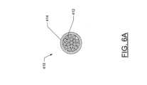
これに関して、図6Aに示すように、光ファイバケーブル410は1つ若しくは複数の光ファイバ412を含んでよい。各光ファイバ412は、図6Bに示されるように、コア412Aとクラッド層412Bとを含むことができる。コアとクラッド層との間の屈折率の差に起因して内部全反射が各光ファイバ412内で生じ得るので、上述のようにそこからの赤外線放射の損失は、ほとんど生じない。さらに、いくつかの実施形態では、光ファイバケーブル410は、赤外線が第2の端部410B(図5参照)以外の場所で光ファイバケーブルに進入するのを実質的に防ぐように構成された遮蔽層414をさらに含むことができる。それによって、赤外線センサ404(図5参照)は、その正確な読み取りを確実にするために、光ファイバケーブル410を使用することなく赤外線センサが構成要素に直接近接して配置された場合とほぼ同量の赤外線を受光することができる。In this regard, as shown in FIG. 6A, the
図5に示されているエアロゾル送達装置感知システム400’の実施形態では、光ファイバケーブル410の第1の端部410Aは、赤外線センサ404のセンサ開口406に直接係合している。しかしながら、図7に示すように、他の実施形態では、エアロゾル送達装置感知システム400’’の温度試験ユニット402は、遮蔽装置416をさらに含んでよい。遮蔽装置416は、赤外線センサ404に結合されてよい。これに関して、遮蔽装置416は、赤外線センサ404によって画定されたセンサ開口406の周りに延在してよい。さらに、光ファイバケーブル410の第1の端部410Aは、遮蔽装置416に結合されてよい。光ファイバケーブル内を通過しなかった赤外線がセンサ開口406に進入するのを実質的に防ぐために、遮蔽装置416が光ファイバケーブル410の第1の端部410Aおよび赤外線センサ404と係合する際、遮蔽装置416は、ほぼ完全に密閉されてよい。したがって、遮蔽装置416を使用することで、光ファイバケーブル410と共に使用するように構成されていない赤外線センサ404をそれと共に使用するように変換することができる。さらに、各遮蔽装置に光ケーブルファイバの第1の端部410Aを受けるように構成された適切にサイズが決められた開口を設けることによって、様々なサイズおよび/または形状を有する様々な光ファイバケーブル410と共に赤外線センサ404を使用できるようにするために、遮蔽装置416は使用されてよい。したがって、遮蔽装置416は、特定のサイズおよび/または形状アダプタであるものとして特徴付けられてよい。In the embodiment of the aerosol delivery device sensing system 400' shown in FIG. 5, the
したがって、赤外線センサ404を使用して、エアロゾル送達装置100の1つ若しくは複数の構成要素から放出された赤外線を検出することができる。上述のように、赤外線センサ404は、赤外線を直接受信するように構成されてもよいが、他の実施形態では、光ファイバケーブル410は、赤外線を受光し、赤外線放射を赤外線センサに誘導するのに使用されてもよい。他の方法ではアクセスすることが不可能であるか、あるいは、エアロゾル送達装置の改良によってのみアクセス可能であり得る、エアロゾル送達装置100内の様々な構成要素へのアクセスを可能する点において、光ファイバケーブル410を使用により、利点を提供することができる。上述のエアロゾル送達装置の改良は、不可逆的であり得、またセンサ読み取り値に影響を与える可能性があり、および/または他の構成要素のテストを妨げる可能性がある。さらに、光ファイバケーブル410を使用することによって、赤外線が受光される目標に対する正確な制御が可能になることがある。これに関して、正確な読み取り値を提供するために、光ファイバケーブル410は、その第2の端部410Bを構成要素に近接して配置することによって単一の構成要素またはその一部に特に向けられ得ることで、赤外線センサ404によって受光される放射は、実質的にその1つの構成要素のみから、またはその一部のみから放射されることになる。対照的に、光ファイバケーブル410なしで赤外線センサ404を使用することは、赤外線センサによって提供される読み取りの精度に影響を及ぼす可能性のある他の構成要素または供給源からの何らかの赤外線放射の受光を許す可能性がある。しかしながら、特定の地点ではなく、より広い領域(例えば、アトマイザの周囲の領域)の温度測定値を得ることが望まれる場合、いくつかの実施形態では、光ファイバケーブル410および/または赤外線センサ404は、例えばレンズを使用することによって、そのようなより広い領域から赤外線を受光するように構成される場合がある。これに関して、一例として、アトマイザを取り囲む領域の温度を知ることが有益である場合があり、このことは、アトマイザの急速な加熱および冷却を考慮してアトマイザのピーク温度よりも有意に低いピーク温度を規定することができる。これに関して、アトマイザの周囲のこの領域における状況は、温度が所望の安全な閾値を下回ったままであることを確実にするために監視されてよい。Thus, the
これにより、例えば構成要素の温度がコントローラ408によって決定され得るように、1つ若しくは複数の構成要素から赤外線が受光されてよい。例えば、図4に示すように、センサ開口406は、アトマイザ410に向けられてよい、または図5および図7に示すように、光ファイバケーブル410の第2の端部410Bは、アトマイザから放出される赤外線を検出するためにアトマイザ310に近接して位置決めされてよい。これにより、赤外線センサ404は、アトマイザ310から受光した赤外線を測定することができる。これに関して、アトマイザの動作が改善され得るように、アトマイザ310の動作中のその温度に関する情報を取得し、記録することが恐らく望ましい。例えば、アトマイザ310の加熱が不十分な範囲であることは、所望されるよりも少ないエアロゾルの生成をもたらす結果になり得る。逆に、アトマイザ310における過度の熱の発生は、電流を消耗し、それによって不必要に急速に電気供給源216(図2参照)を使い果たす可能性がある。さらに、過度の熱の発生は、エアロゾル送達装置100の構成要素を損傷させる可能性があり、および/または他の問題を引き起こす可能性がある。追加として、各パフに関する所望される継続時間にわたってエアロゾルが生成されるように、アトマイザ310が加熱および冷却する速度が監視されてもよい。さらに、多すぎる熱は、エアロゾル前駆体組成物および/または生成されたエアロゾルを劣化させる、および/またはその香味に悪影響を及ぼす可能性がある。したがって、アトマイザ310を監視することは、アトマイザ310が所望の量の熱を生成し、所望の速度で加熱/冷却することを確実にするために採用されてよい。This may allow infrared radiation to be received from one or more components such that, for example, the temperature of the components may be determined by the
したがって、上述のように、赤外線センサ404は、その動作を分析するために使用することができるエアロゾル送達装置100とは別の外部装置として温度試験ユニット402に含めることができる。したがって、温度試験ユニット402は、研究開発、および製造されたエアロゾル送達装置の品質管理などの目的のためにエアロゾル送達装置100の動作を分析するために使用することができる。それにより、例えば、コントローラ212(図2参照)は、試験中に赤外線センサが受光した赤外線に基づいてアトマイザ310に所望の量の熱を発生させるように構成された加熱プロファイルに従ってプログラムされてよい。しかしながら、エアロゾル送達装置の個々の構成要素、周囲条件、電気供給源216(図2参照)内の残留電荷量、および/または様々な他の要因の変動によって、アトマイザ310によって生成される実際の熱が実験室環境で監視される熱と異なる場合がある。Thus, as described above, the
したがって、図8は、本開示の追加の実施形態によるエアロゾル送達装置感知システム500を示す。図示のように、一実施形態では、エアロゾル送達装置感知システム500はエアロゾル送達装置を含むことができ、それは、上述のエアロゾル送達装置100の構成要素の一部または全てを含むことができる。例えば、エアロゾル送達装置感知システム500は、カートリッジ300および制御体200を含むことができる。図示のように、制御体200は、コントローラ212と、電気供給源216とを含んでよい。カートリッジ300は、外側本体314内に収容されたアトマイザ310を含むことができる。8 thus illustrates an aerosol delivery
さらに、カートリッジ300は、外側本体314内に収容された赤外線センサ404を含むことができる。これにより、赤外線センサは、エアロゾル送達装置感知システム500内の構成要素から受光した赤外線を測定することができる。例えば、赤外線センサ404は、カートリッジ300内の構成要素からの赤外線を測定するように構成されてよい。さらなる例として、赤外線センサ404は、アトマイザ310によって生成され、そこから受光した赤外線を測定するように構成されてもよい。Additionally, the
図8に示すように、いくつかの実施形態では、赤外線センサ404は、センサ開口406が、アトマイザ310など、そこから放出される赤外線の測定が望まれる構成要素に直接面するように配置することができる。しかしながら、他の実施形態では、カートリッジ300内の構成要素の構成が、センサ開口406が、そこから放出される赤外線の測定が望まれる構成要素に直接面することができない場合がある。As shown in FIG. 8, in some embodiments, the
例として、図9は、カートリッジ300の追加の構成要素、特に図示の実施形態におけるリザーバ312が赤外線センサ404とアトマイザ310との間に配置されているエアロゾル送達装置感知システム500’の実施形態を示している。これにより、センサ開口406は、アトマイザ310から赤外線を受光するためにアトマイザ310に直接面していない場合がある。しかしながら、エアロゾル送達装置感知システム500’は、光ファイバケーブル410をさらに含んでもよい。これにより、光ファイバケーブルの第1の端部410Aは、赤外線センサ404に近接して位置決めされ、第2の端部410Bは、アトマイザ310に近接して位置決めされてよい。したがって、光ファイバケーブル410は、第2の端部410Bが、そこから放射される赤外線の検出が望まれる構成要素に面するように適切であるように位置決めされてよい。これに関して、光ファイバケーブル410の可撓性および比較的小さい断面寸法は、外側本体314内のそれらの相対的な配置にかかわらず、カートリッジ300の構成要素の一部または全ての赤外線センサ404による感知を可能にすることがある。一実施形態では、光ファイバケーブル410は、約0.25mmから約10mmの直径を規定することができる。9 shows an embodiment of an aerosol delivery device sensing system 500' in which additional components of the
センサ開口406がアトマイザ310に直接面するかどうか、または赤外線が光ファイバケーブル410を介して赤外線センサ404に向けられるかどうかにかかわらず、赤外線センサから受信した情報をアトマイザ310の動作を制御するために使用することができる。これに関して、コントローラ212は、受光した赤外線に対応する赤外線センサ404から信号を受信することができる。信号は、赤外線センサ404から直接または電子部品306を介してコントローラ212によって受信されてよい。電子部品306を介して赤外線センサ404からコントローラ212に信号を提供することは、追加のコネクタの使用を必要としないことによってカートリッジ300と制御体200との間の接続を単純化することができる。これに関して、信号は、電子部品端子304(図3参照)を介して送信されてもよい。Regardless of whether the
これにより、コントローラ212は、赤外線センサ404からの信号に応答して、電気供給源216からアトマイザ310への電流の供給を制御することができる。例えば、コントローラ212は、赤外線センサ404からの信号に応答してアトマイザ310への電流の供給を増減することができる。さらなる例として、赤外線センサ404からの信号が所定量の赤外線を放射しているアトマイザ310に対応しており、これによりアトマイザが所定の温度に達することに相当する場合、アトマイザへの電流の供給を減少させる、または止めることができる。This allows the
これにより、アトマイザ310への電流の供給不足または供給過剰に関する問題を回避することができる。これに関して、アトマイザ310への電流の供給は、赤外線センサ404からの信号に応答して実質的にリアルタイムで調整することができる。したがって、アトマイザ310への電流の供給は、アトマイザの温度に対応する赤外線センサ404からの信号を考慮して、アトマイザの温度に応じて実質的にリアルタイムで調整することができる。This avoids problems with under- or over-supplying current to the
図9に示されるエアロゾル送達装置感知システム500’の実施形態では、光ファイバケーブル410がセンサ開口406に直接係合することに留意されたい。しかしながら、理解され得るように、他の実施形態では、図7に関して上述したように遮蔽装置が赤外線センサと光ファイバケーブルの両方と係合する場合もある。Note that in the embodiment of the aerosol delivery device sensing system 500' shown in FIG. 9, the
さらなる態様において、エアロゾル送達装置を用いた蒸気生成のための方法が提供される。図10に示されるように、本方法は、工程602において、外側本体と、加熱要素を含むアトマイザとを設けることを含んでよい。アトマイザは外側本体に収容されてよい。さらに、本方法は、工程604において赤外線センサを設けることを含んでよい。さらに、本方法は、工程606において、アトマイザによって生成された赤外線を、赤外線センサを用いて測定することを含んでよい。In a further aspect, a method for vapor generation using an aerosol delivery device is provided. As shown in FIG. 10, the method may include providing an outer body and an atomizer including a heating element at
本方法は、光ファイバケーブルの第1の端部を赤外線センサに近接して位置決めすることをさらに含んでよい。さらに、この方法は、光ファイバケーブルの第2の端部をアトマイザに近接して位置決めすることを含んでよい。工程606において、アトマイザによって生成された赤外線を、赤外線センサを用いて測定することは、光ファイバケーブルを介してアトマイザから受光した赤外線を測定することを含んでよい。The method may further include positioning a first end of the fiber optic cable proximate to an infrared sensor. Additionally, the method may include positioning a second end of the fiber optic cable proximate to the atomizer. In
本方法は、遮蔽装置が赤外線センサによって画定されたセンサ開口の周りに延在するように、遮蔽装置をセンサ組立体に結合することをさらに含んでよい。さらに、この方法は、遮蔽装置を光ファイバケーブルの第1の端部に結合することを含んでよい。遮蔽装置をセンサ組立体および光ファイバケーブルの第1の端部に結合することは、遮蔽装置をほぼ完全に密閉して光ファイバケーブル内を通っていない赤外線がセンサ開口に進入するのを実質的に阻止することを含んでよい。The method may further include coupling the shielding device to the sensor assembly such that the shielding device extends around a sensor opening defined by the infrared sensor. Additionally, the method may include coupling the shielding device to a first end of the fiber optic cable. Coupling the shielding device to the sensor assembly and the first end of the fiber optic cable may include substantially completely sealing the shielding device to substantially prevent infrared radiation not passing through the fiber optic cable from entering the sensor opening.
さらに、この方法は、遮蔽層を有する、第2の端部以外の場所で赤外線が光ファイバケーブルに進入するのを実質的に防ぐことを含むことができる。さらに、この方法は、赤外線センサを外側本体内に配置することを含んでよい。工程606において、アトマイザによって生成された赤外線放射を、赤外線センサを用いて測定することは、赤外線センサからの信号に応答してアトマイザに供給される電流を制御することを含んでよい。The method may further include substantially preventing infrared radiation from entering the fiber optic cable at locations other than the second end with a shielding layer. The method may further include disposing an infrared sensor within the outer body. In
本方法は、コントローラを設けることをさらに含んでよい。赤外線センサからの信号に応答してアトマイザに供給される電流を制御することは、コントローラを用いてアトマイザに供給される電流を制御することを含んでよい。本方法は、赤外線センサを外側本体の外側に配置することをさらに含んでよい。さらに、光ファイバケーブルの第2の端部をアトマイザに近接して位置決めすることは、光ファイバケーブルを外側本体内に挿入することを含んでよい。The method may further include providing a controller. Controlling the current supplied to the atomizer in response to a signal from the infrared sensor may include controlling the current supplied to the atomizer with the controller. The method may further include disposing the infrared sensor outside the outer body. Additionally, positioning the second end of the fiber optic cable proximate to the atomizer may include inserting the fiber optic cable into the outer body.
上記のように、エアロゾル送達装置の構成要素から放出される赤外線は、それぞれ制御またはテスト目的のためにエアロゾル送達装置の内部または外部にあるような赤外線センサで検出されてよい。放出された放射線が感知されるそのような構成要素は、エアロゾル送達装置の外部本体の内部にあってもよい。本開示から、カートリッジの外側本体またはエアロゾル送達装置の制御体内にあるものとしての構成要素への言及は、例示目的のみのためであることが理解されるべきである。他の実施形態では、エアロゾル送達装置は、単一の外側本体を含む場合がある。したがって、一般的に言えば、赤外線センサは、送達装置の外部本体内の構成要素から受光した赤外線を感知することができる。As noted above, infrared radiation emitted from a component of the aerosol delivery device may be detected with an infrared sensor, such as one that is internal or external to the aerosol delivery device for control or testing purposes, respectively. Such a component from which the emitted radiation is sensed may be within the external body of the aerosol delivery device. It should be understood from this disclosure that references to components as being within the outer body of a cartridge or the control body of an aerosol delivery device are for illustrative purposes only. In other embodiments, the aerosol delivery device may include a single outer body. Thus, generally speaking, an infrared sensor may sense infrared radiation received from a component within the external body of the delivery device.
本開示は全体的に、アトマイザによって加熱されたエアロゾル送達装置の他の構成要素からではなく、アトマイザから放出された赤外線放射を測定することを説明している。言い換えれば、本開示は全体的に、アトマイザによって直接放出された赤外線放射を測定することを説明している。いくつかの実施形態では、赤外線センサは、赤外線センサまたは光ファイバケーブルを加熱要素または液体輸送要素などのアトマイザの一部分に特に向けることによって、アトマイザのそういった部分からの赤外線を受光するように構成されてもよい。液体輸送要素から放出される赤外線を測定することは、エアロゾル前駆体組成物が被る温度条件に関してより正確な読み取り値を提供することができるが、一方、加熱要素から放出される赤外線を測定することは、その所望される最大温度を超えないように、エアロゾル送達装置内でどれが全体的に最も高い温度の構成要素であるかに関する情報を提供することができる。The present disclosure generally describes measuring infrared radiation emitted from the atomizer, rather than from other components of the aerosol delivery device that are heated by the atomizer. In other words, the present disclosure generally describes measuring infrared radiation emitted directly by the atomizer. In some embodiments, the infrared sensor may be configured to receive infrared radiation from a portion of the atomizer, such as a heating element or a liquid transport element, by specifically aiming the infrared sensor or fiber optic cable at such a portion. Measuring infrared radiation emitted from a liquid transport element can provide a more accurate reading as to the temperature conditions experienced by the aerosol precursor composition, while measuring infrared radiation emitted from a heating element can provide information regarding which is the overall hottest component in the aerosol delivery device, so as not to exceed its desired maximum temperature.
しかしながら、他の実施形態では、エアロゾル送達装置の他の構成要素のいずれかによって放出された赤外線が赤外線センサによって測定される場合もある。これにより、例えば、エアロゾル送達装置の動作が、1つ若しくは複数の構成要素が損傷する恐れのある、そのような構成要素に関する温度閾値を超えないことを確実にすることができる。さらなる例として、赤外線センサは、使用者が触れる可能性のあるエアロゾル送達装置の構成要素の温度を制限するために、外部からアクセス可能なエアロゾル送達装置の構成要素(例えば、カートリッジの外部本体)の温度を検出する場合がある。However, in other embodiments, infrared radiation emitted by any of the other components of the aerosol delivery device may be measured by the infrared sensor. This may, for example, ensure that operation of the aerosol delivery device does not exceed temperature thresholds for one or more components that may be damaged. As a further example, the infrared sensor may detect the temperature of an externally accessible component of the aerosol delivery device (e.g., the external body of the cartridge) in order to limit the temperature of components of the aerosol delivery device that may be touched by a user.
本開示の実施形態は、概して、円形断面を画定するものとして光ファイバケーブルを説明しているが、他の実施形態では、光ファイバケーブルは、長方形などの異なる形状を有する断面を画定してもよい。これに関して、光ファイバケーブルの断面は、代替的な形状を有するエアロゾル送達装置内のオリフィスまたは空間と一致するようにとりわけ調整されてもよい。別の実施形態では、エアロゾル送達装置上のおよび/またはその構成要素上の複数の位置から受光した赤外線を同時に測定するために、複数の赤外線センサが使用される場合がある。これに関して、各赤外線センサは、異なる構成要素または構成要素の異なる部分を対象とすることができる。理解され得るように、いくつかの実施形態では、そこから発する放射を直接測定することが困難であり得る場所からの赤外放射を受光するために、複数の赤外センサの1つ若しくは複数が光ファイバケーブルと係合されてよい。したがって、複数の光ファイバケーブルが、各光ファイバケーブルが異なる赤外線センサにおいて、かつエアロゾル送達装置内の異なる位置において終端するいくつかの実施形態で使用されてよく、または複数の光ファイバケーブルが単一の赤外線センサに接続されてもよい。While embodiments of the present disclosure generally describe the fiber optic cable as defining a circular cross-section, in other embodiments, the fiber optic cable may define a cross-section having a different shape, such as a rectangle. In this regard, the cross-section of the fiber optic cable may be tailored, among other things, to match an orifice or space within the aerosol delivery device having an alternative shape. In another embodiment, multiple infrared sensors may be used to simultaneously measure infrared radiation received from multiple locations on the aerosol delivery device and/or on its components. In this regard, each infrared sensor may be directed to a different component or different portion of a component. As can be appreciated, in some embodiments, one or more of multiple infrared sensors may be engaged with the fiber optic cable to receive infrared radiation from a location where it may be difficult to directly measure radiation emanating therefrom. Thus, multiple fiber optic cables may be used in some embodiments where each fiber optic cable terminates at a different infrared sensor and at a different location within the aerosol delivery device, or multiple fiber optic cables may be connected to a single infrared sensor.
本開示は概して、エアロゾル送達装置の構成要素から放出される赤外線を測定するために本明細書に開示されるシステムを使用することに関するが、他の実施形態では、本明細書に開示されるシステムは、任意の他の装置から放出する赤外線を測定するために使用される場合もある。これに関して、光ファイバケーブルの使用は、厳しい公差および/または実質的に切れ目のない外側本体がその中の構成要素への直接のアクセスを妨げる任意の装置において特に有利であることがある。Although the present disclosure generally relates to using the systems disclosed herein to measure infrared radiation emitted from components of an aerosol delivery device, in other embodiments, the systems disclosed herein may be used to measure infrared radiation emitted from any other device. In this regard, the use of fiber optic cables may be particularly advantageous in any device where tight tolerances and/or a substantially unbroken outer body preclude direct access to components therein.
本開示が関連する当業者には、前述の説明および関連する図面に提示された教示の恩恵を受けて、本開示の多くの修正形態および他の態様が思い浮かぶであろう。したがって、本開示は、本明細書に開示された特定の態様に限定されるべきではなく、修正形態および他の態様は、添付の特許請求の範囲内に含まれることが意図されることを理解されたい。本明細書では特定の用語が使用されているが、それらは一般的かつ説明的な意味でのみ使用されており、限定の目的では使用されていない。Many modifications and other aspects of the disclosure will come to mind to one skilled in the art to which this disclosure pertains having the benefit of the teachings presented in the foregoing descriptions and the associated drawings. It is to be understood, therefore, that the disclosure is not to be limited to the specific aspects disclosed herein, and that modifications and other aspects are intended to be included within the scope of the appended claims. Although specific terms are employed herein, they are used in a generic and descriptive sense only and not for purposes of limitation.
Claims (16)
Translated fromJapanese外側本体に収容され、電源によって駆動される加熱要素と、
外側本体内の構成要素によって生成された赤外線を測定するように構成された赤外線センサであって、構成要素は、電源によって駆動される加熱要素である、赤外線センサと、
赤外線センサに近接して位置決めされた第1の端部と、赤外線を生成する、外側本体内の構成要素に近接して位置決めされた第2の端部とを有する光ファイバケーブルと
を備え、
赤外線センサは、光ファイバケーブルを介して、赤外線を生成する、外側本体内の構成要素から受光した赤外線を測定するように構成されている、エアロゾル送達装置感知システム。 An outer body;
a heating element housed in the outer body and powered by a power source;
an infrared sensor configured to measure infrared radiation generated by a component within the outer body, the componentbeing a heating element powered by a power source; and
a fiber optic cable having a first end positioned proximate to the infrared sensor and a second end positioned proximate to a component within the outer body that generates the infrared radiation;
An aerosol delivery device sensing system, wherein the infrared sensor is configured to measure infrared radiation received from a component within the outer body that generates the infrared radiation via the fiber optic cable.
光ファイバケーブルの第1の端部が、遮蔽装置に結合されている、請求項1に記載のエアロゾル送達装置感知システム。 a shielding device coupled to the infrared sensor and extending around a sensor opening defined by the infrared sensor;
The aerosol delivery device sensing system of claim 1 , wherein a first end of the fiber optic cable is coupled to the shielding device.
赤外線センサを設けることと、
光ファイバケーブルの第1の端部を赤外線センサに近接して位置決めすることと、
光ファイバケーブルの第2の端部を、赤外線を生成する、外側本体内の構成要素に近接して位置決めすることであって、構成要素は、電源によって駆動される加熱要素である、ことと、
外側本体内の構成要素によって生成された赤外線を、赤外線センサを用いて測定することと、
を含み、
赤外線は、構成要素から光ファイバケーブルを介して受光される、エアロゾル送達装置の温度監視方法。 providing an outer body and a heating element housed within the outer body and powered by a power source;
Providing an infrared sensor;
positioning a first end of a fiber optic cable proximate to an infrared sensor;
positioning a second end of the fiber optic cable proximate to a component within the outer body that generates infrared radiation, the componentbeing a heating element powered by a power source;
measuring infrared radiation generated by components within the outer body with an infrared sensor;
Including,
A method for monitoring the temperature of an aerosol delivery device, wherein infrared light is received from a component via a fiber optic cable.
遮蔽装置を光ファイバケーブルの第1の端部に結合することと、
をさらに含む、請求項9に記載のエアロゾル送達装置の温度監視方法。 coupling a shielding device to the sensor assembly such that the shielding device extends around a sensor opening defined by the infrared sensor;
coupling a shielding device to a first end of a fiber optic cable;
10. The method of claim 9, further comprising:
Applications Claiming Priority (4)
| Application Number | Priority Date | Filing Date | Title |
|---|---|---|---|
| US15/374,220US11013266B2 (en) | 2016-12-09 | 2016-12-09 | Aerosol delivery device sensory system including an infrared sensor and related method |
| US15/374,220 | 2016-12-09 | ||
| JP2019530823AJP7408390B2 (en) | 2016-12-09 | 2017-12-08 | Aerosol delivery device sensing system including infrared sensor and related method |
| PCT/IB2017/057760WO2018104920A1 (en) | 2016-12-09 | 2017-12-08 | Aerosol delivery device sensory system including an infrared sensor and related method |
Related Parent Applications (1)
| Application Number | Title | Priority Date | Filing Date |
|---|---|---|---|
| JP2019530823ADivisionJP7408390B2 (en) | 2016-12-09 | 2017-12-08 | Aerosol delivery device sensing system including infrared sensor and related method |
Publications (2)
| Publication Number | Publication Date |
|---|---|
| JP2023025069A JP2023025069A (en) | 2023-02-21 |
| JP7633223B2true JP7633223B2 (en) | 2025-02-19 |
Family
ID=60782292
Family Applications (2)
| Application Number | Title | Priority Date | Filing Date |
|---|---|---|---|
| JP2019530823AActiveJP7408390B2 (en) | 2016-12-09 | 2017-12-08 | Aerosol delivery device sensing system including infrared sensor and related method |
| JP2022183891AActiveJP7633223B2 (en) | 2016-12-09 | 2022-11-17 | Aerosol delivery device sensing system including an infrared sensor and related methods - Patents.com |
Family Applications Before (1)
| Application Number | Title | Priority Date | Filing Date |
|---|---|---|---|
| JP2019530823AActiveJP7408390B2 (en) | 2016-12-09 | 2017-12-08 | Aerosol delivery device sensing system including infrared sensor and related method |
Country Status (8)
| Country | Link |
|---|---|
| US (1) | US11013266B2 (en) |
| EP (1) | EP3550997B1 (en) |
| JP (2) | JP7408390B2 (en) |
| KR (2) | KR102584921B1 (en) |
| CN (1) | CN110418580A (en) |
| PL (1) | PL3550997T3 (en) |
| RU (1) | RU2758317C2 (en) |
| WO (1) | WO2018104920A1 (en) |
Families Citing this family (19)
| Publication number | Priority date | Publication date | Assignee | Title |
|---|---|---|---|---|
| CN105077592B (en)* | 2015-07-02 | 2019-03-15 | 天津希格玛微电子技术有限公司 | Electronic cigarette, tobacco rod, smoke grenade and the recognition methods for smoke grenade |
| USD840854S1 (en)* | 2016-05-25 | 2019-02-19 | Kone Corporation | Cylindrical emergency signaling device |
| US11013266B2 (en) | 2016-12-09 | 2021-05-25 | Rai Strategic Holdings, Inc. | Aerosol delivery device sensory system including an infrared sensor and related method |
| USD883124S1 (en)* | 2018-04-27 | 2020-05-05 | James C. Martine | Item locator |
| GB201812062D0 (en)* | 2018-07-24 | 2018-09-05 | Nicoventures Trading Ltd | A power module for a modular aerosol generating device, a module for a modular aerosole generating device and a modular aerosol generating device |
| US11882438B2 (en)* | 2018-10-29 | 2024-01-23 | Zorday IP, LLC | Network-enabled electronic cigarette |
| KR102271274B1 (en)* | 2019-05-16 | 2021-06-30 | 주식회사 케이티앤지 | Aerosol generating device and method for controlling same |
| KR20220019816A (en)* | 2019-06-14 | 2022-02-17 | 필립모리스 프로덕츠 에스.에이. | Aerosol-generating device with optical means for condition detection |
| EP3982777B1 (en)* | 2019-06-17 | 2023-06-07 | Fraunhofer-Gesellschaft zur Förderung der angewandten Forschung e.V. | Sensor module for determining an aerosol dose rate |
| US10923160B2 (en)* | 2019-07-05 | 2021-02-16 | Seagate Technology Llc | Testing assembly for sealed hard disk drives |
| US11754635B2 (en)* | 2019-07-12 | 2023-09-12 | Rai Strategic Holdings, Inc. | Power unit test system and method |
| WO2021170465A1 (en)* | 2020-02-26 | 2021-09-02 | Jt International S.A. | Heat-not-burn aerosol-generating device comprising means for authenticating an aerosol-generating article by internal illumination thereof |
| KR102423898B1 (en)* | 2020-04-16 | 2022-07-21 | 주식회사 케이티앤지 | Aerosol generating device |
| CN111869927A (en)* | 2020-08-06 | 2020-11-03 | 深圳市康泓威科技有限公司 | Heating temperature adjustable baking smoke set |
| USD957732S1 (en)* | 2020-09-12 | 2022-07-12 | Highlightz International, Inc. | Smoker's article |
| CN114158786A (en)* | 2021-11-26 | 2022-03-11 | 深圳麦克韦尔科技有限公司 | Heating element and aerosol-generating device |
| CN114831345B (en)* | 2022-06-01 | 2024-12-13 | 深圳市赛尔美电子科技有限公司 | Atomizer temperature test system and test method |
| CN115104787A (en)* | 2022-07-18 | 2022-09-27 | 东莞市阿尔法电子科技有限公司 | Atomization device control method, system and atomization device based on non-contact detection |
| CN115736379A (en)* | 2022-12-29 | 2023-03-07 | 思摩尔国际控股有限公司 | Band-shaped atomizing medium and aerosol generating device |
Citations (3)
| Publication number | Priority date | Publication date | Assignee | Title |
|---|---|---|---|---|
| JP2010033043A (en) | 2008-06-23 | 2010-02-12 | Mitsubishi Rayon Co Ltd | Plastic optical fiber cable and signal transmission method |
| CN204157655U (en) | 2014-10-24 | 2015-02-18 | 林光榕 | Infrared induction temperature control electronic cigarette |
| JP2020513245A (en) | 2016-12-09 | 2020-05-14 | アール・エイ・アイ・ストラテジック・ホールディングス・インコーポレイテッド | Aerosol delivery device sensing system including infrared sensor and related methods |
Family Cites Families (225)
| Publication number | Priority date | Publication date | Assignee | Title |
|---|---|---|---|---|
| US2057353A (en) | 1936-10-13 | Vaporizing unit fob therapeutic | ||
| US1771366A (en) | 1926-10-30 | 1930-07-22 | R W Cramer & Company Inc | Medicating apparatus |
| US2104266A (en) | 1935-09-23 | 1938-01-04 | William J Mccormick | Means for the production and inhalation of tobacco fumes |
| GB1014779A (en) | 1962-11-16 | 1965-12-31 | American Pyrotector Inc | Improvements in or relating to radiation detectors |
| US3200819A (en) | 1963-04-17 | 1965-08-17 | Herbert A Gilbert | Smokeless non-tobacco cigarette |
| US4284089A (en) | 1978-10-02 | 1981-08-18 | Ray Jon P | Simulated smoking device |
| US4303083A (en) | 1980-10-10 | 1981-12-01 | Burruss Jr Robert P | Device for evaporation and inhalation of volatile compounds and medications |
| US4639368A (en) | 1984-08-23 | 1987-01-27 | Farmacon Research Corporation | Chewing gum containing a medicament and taste maskers |
| SE8405479D0 (en) | 1984-11-01 | 1984-11-01 | Nilsson Sven Erik | WANT TO ADMINISTER VOCABULARY, PHYSIOLOGY, ACTIVE SUBJECTS AND DEVICE FOR THIS |
| JPH0215280Y2 (en)* | 1984-12-27 | 1990-04-24 | ||
| US4735217A (en) | 1986-08-21 | 1988-04-05 | The Procter & Gamble Company | Dosing device to provide vaporized medicament to the lungs as a fine aerosol |
| JPS63292027A (en) | 1987-05-26 | 1988-11-29 | Babcock Hitachi Kk | Temperature sensor |
| GB8713645D0 (en) | 1987-06-11 | 1987-07-15 | Imp Tobacco Ltd | Smoking device |
| US5019122A (en) | 1987-08-21 | 1991-05-28 | R. J. Reynolds Tobacco Company | Smoking article with an enclosed heat conductive capsule containing an aerosol forming substance |
| US4922901A (en) | 1988-09-08 | 1990-05-08 | R. J. Reynolds Tobacco Company | Drug delivery articles utilizing electrical energy |
| US4947875A (en) | 1988-09-08 | 1990-08-14 | R. J. Reynolds Tobacco Company | Flavor delivery articles utilizing electrical energy |
| US4947874A (en) | 1988-09-08 | 1990-08-14 | R. J. Reynolds Tobacco Company | Smoking articles utilizing electrical energy |
| US4986286A (en) | 1989-05-02 | 1991-01-22 | R. J. Reynolds Tobacco Company | Tobacco treatment process |
| US4945931A (en) | 1989-07-14 | 1990-08-07 | Brown & Williamson Tobacco Corporation | Simulated smoking device |
| US5154192A (en) | 1989-07-18 | 1992-10-13 | Philip Morris Incorporated | Thermal indicators for smoking articles and the method of application of the thermal indicators to the smoking article |
| US5178878A (en) | 1989-10-02 | 1993-01-12 | Cima Labs, Inc. | Effervescent dosage form with microparticles |
| US5223264A (en) | 1989-10-02 | 1993-06-29 | Cima Labs, Inc. | Pediatric effervescent dosage form |
| US5144962A (en) | 1989-12-01 | 1992-09-08 | Philip Morris Incorporated | Flavor-delivery article |
| US5224498A (en) | 1989-12-01 | 1993-07-06 | Philip Morris Incorporated | Electrically-powered heating element |
| US5060671A (en) | 1989-12-01 | 1991-10-29 | Philip Morris Incorporated | Flavor generating article |
| US5093894A (en) | 1989-12-01 | 1992-03-03 | Philip Morris Incorporated | Electrically-powered linear heating element |
| US5408574A (en) | 1989-12-01 | 1995-04-18 | Philip Morris Incorporated | Flat ceramic heater having discrete heating zones |
| US5042510A (en) | 1990-01-08 | 1991-08-27 | Curtiss Philip F | Simulated cigarette |
| DE4004408A1 (en) | 1990-02-13 | 1991-08-14 | Ultrakust Electronic Gmbh | IR temp. sensor for high temps. |
| US5591368A (en) | 1991-03-11 | 1997-01-07 | Philip Morris Incorporated | Heater for use in an electrical smoking system |
| US5388594A (en) | 1991-03-11 | 1995-02-14 | Philip Morris Incorporated | Electrical smoking system for delivering flavors and method for making same |
| US5726421A (en) | 1991-03-11 | 1998-03-10 | Philip Morris Incorporated | Protective and cigarette ejection system for an electrical smoking system |
| US5249586A (en) | 1991-03-11 | 1993-10-05 | Philip Morris Incorporated | Electrical smoking |
| US5665262A (en) | 1991-03-11 | 1997-09-09 | Philip Morris Incorporated | Tubular heater for use in an electrical smoking article |
| US5530225A (en) | 1991-03-11 | 1996-06-25 | Philip Morris Incorporated | Interdigitated cylindrical heater for use in an electrical smoking article |
| US5505214A (en) | 1991-03-11 | 1996-04-09 | Philip Morris Incorporated | Electrical smoking article and method for making same |
| US5573692A (en) | 1991-03-11 | 1996-11-12 | Philip Morris Incorporated | Platinum heater for electrical smoking article having ohmic contact |
| US5261424A (en) | 1991-05-31 | 1993-11-16 | Philip Morris Incorporated | Control device for flavor-generating article |
| US5228460A (en) | 1991-12-12 | 1993-07-20 | Philip Morris Incorporated | Low mass radial array heater for electrical smoking article |
| IL104930A (en) | 1992-03-25 | 1995-12-31 | Reynolds Tobacco Co R | Components for smoking articles and their manufacture |
| US5353813A (en) | 1992-08-19 | 1994-10-11 | Philip Morris Incorporated | Reinforced carbon heater with discrete heating zones |
| US5322075A (en) | 1992-09-10 | 1994-06-21 | Philip Morris Incorporated | Heater for an electric flavor-generating article |
| US5498850A (en) | 1992-09-11 | 1996-03-12 | Philip Morris Incorporated | Semiconductor electrical heater and method for making same |
| US5369723A (en) | 1992-09-11 | 1994-11-29 | Philip Morris Incorporated | Tobacco flavor unit for electrical smoking article comprising fibrous mat |
| US5498855A (en) | 1992-09-11 | 1996-03-12 | Philip Morris Incorporated | Electrically powered ceramic composite heater |
| US5441060A (en) | 1993-02-08 | 1995-08-15 | Duke University | Dry powder delivery system |
| US5372148A (en) | 1993-02-24 | 1994-12-13 | Philip Morris Incorporated | Method and apparatus for controlling the supply of energy to a heating load in a smoking article |
| US5468936A (en) | 1993-03-23 | 1995-11-21 | Philip Morris Incorporated | Heater having a multiple-layer ceramic substrate and method of fabrication |
| US5666977A (en) | 1993-06-10 | 1997-09-16 | Philip Morris Incorporated | Electrical smoking article using liquid tobacco flavor medium delivery system |
| DK0706352T3 (en) | 1993-06-29 | 2002-07-15 | Ponwell Entpr Ltd | Dispenser |
| US5388574A (en) | 1993-07-29 | 1995-02-14 | Ingebrethsen; Bradley J. | Aerosol delivery article |
| CH686872A5 (en) | 1993-08-09 | 1996-07-31 | Disetronic Ag | Medical Inhalationsgeraet. |
| DE4328243C1 (en) | 1993-08-19 | 1995-03-09 | Sven Mielordt | Smoke or inhalation device |
| IE72523B1 (en) | 1994-03-10 | 1997-04-23 | Elan Med Tech | Nicotine oral delivery device |
| GB9517062D0 (en) | 1995-08-18 | 1995-10-25 | Scherer Ltd R P | Pharmaceutical compositions |
| US5649554A (en) | 1995-10-16 | 1997-07-22 | Philip Morris Incorporated | Electrical lighter with a rotatable tobacco supply |
| US5564442A (en) | 1995-11-22 | 1996-10-15 | Angus Collingwood MacDonald | Battery powered nicotine vaporizer |
| US5743251A (en) | 1996-05-15 | 1998-04-28 | Philip Morris Incorporated | Aerosol and a method and apparatus for generating an aerosol |
| DE69724559T2 (en) | 1996-06-17 | 2004-07-15 | Japan Tobacco Inc. | FLAVORED ARTICLE |
| US6125853A (en) | 1996-06-17 | 2000-10-03 | Japan Tobacco, Inc. | Flavor generation device |
| US6089857A (en) | 1996-06-21 | 2000-07-18 | Japan Tobacco, Inc. | Heater for generating flavor and flavor generation appliance |
| US5934289A (en) | 1996-10-22 | 1999-08-10 | Philip Morris Incorporated | Electronic smoking system |
| US6040560A (en) | 1996-10-22 | 2000-03-21 | Philip Morris Incorporated | Power controller and method of operating an electrical smoking system |
| US5878752A (en) | 1996-11-25 | 1999-03-09 | Philip Morris Incorporated | Method and apparatus for using, cleaning, and maintaining electrical heat sources and lighters useful in smoking systems and other apparatuses |
| US5865186A (en) | 1997-05-21 | 1999-02-02 | Volsey, Ii; Jack J | Simulated heated cigarette |
| KR100289448B1 (en) | 1997-07-23 | 2001-05-02 | 미즈노 마사루 | Flavor generator |
| US5954979A (en) | 1997-10-16 | 1999-09-21 | Philip Morris Incorporated | Heater fixture of an electrical smoking system |
| US5967148A (en) | 1997-10-16 | 1999-10-19 | Philip Morris Incorporated | Lighter actuation system |
| DE1149602T1 (en) | 1997-11-19 | 2002-04-04 | Microflow Engineering S.A., Neuenburg/Neuchatel | Spray device for an inhaler suitable for respiratory therapy |
| CN1044314C (en) | 1997-12-01 | 1999-07-28 | 蒲邯名 | Healthy cigarette |
| US6974590B2 (en) | 1998-03-27 | 2005-12-13 | Cima Labs Inc. | Sublingual buccal effervescent |
| US6164287A (en) | 1998-06-10 | 2000-12-26 | R. J. Reynolds Tobacco Company | Smoking method |
| US6095153A (en) | 1998-06-19 | 2000-08-01 | Kessler; Stephen B. | Vaporization of volatile materials |
| US6234167B1 (en) | 1998-10-14 | 2001-05-22 | Chrysalis Technologies, Incorporated | Aerosol generator and methods of making and using an aerosol generator |
| US6053176A (en) | 1999-02-23 | 2000-04-25 | Philip Morris Incorporated | Heater and method for efficiently generating an aerosol from an indexing substrate |
| US6196218B1 (en) | 1999-02-24 | 2001-03-06 | Ponwell Enterprises Ltd | Piezo inhaler |
| CA2385324C (en) | 1999-09-22 | 2008-03-25 | Miodrag Oljaca | Liquid atomization methods and devices |
| CA2403378C (en) | 2000-03-23 | 2010-01-05 | Philip Morris Products Inc. | Electrical smoking system and method |
| US7559324B2 (en) | 2000-06-21 | 2009-07-14 | Fisher & Paykel Healthcare Limited | Conduit with heated wick |
| EP1247447B1 (en) | 2001-04-05 | 2004-09-15 | C.T.R., Consultoria, Técnica e Representaçoes Lda | Device for vaporising fluids, particularly insecticides and/or perfumes |
| US6598607B2 (en) | 2001-10-24 | 2003-07-29 | Brown & Williamson Tobacco Corporation | Non-combustible smoking device and fuel element |
| AU2002357599A1 (en) | 2001-12-28 | 2003-07-24 | Japan Tobacco Inc. | Smoking implement |
| US6772756B2 (en) | 2002-02-09 | 2004-08-10 | Advanced Inhalation Revolutions Inc. | Method and system for vaporization of a substance |
| US6615840B1 (en) | 2002-02-15 | 2003-09-09 | Philip Morris Incorporated | Electrical smoking system and method |
| AU2003222642A1 (en) | 2002-05-10 | 2003-11-11 | Chrysalis Technologies Incorporated | Aerosol generator for drug formulation and methods of generating aerosol |
| US6803545B2 (en) | 2002-06-05 | 2004-10-12 | Philip Morris Incorporated | Electrically heated smoking system and methods for supplying electrical power from a lithium ion power source |
| CN1700934B (en) | 2002-09-06 | 2011-08-03 | 菲利普莫里斯美国公司 | Liquid aerosol preparation and aerosol generating device and method for preparing aerosol |
| CA2502171C (en) | 2002-10-31 | 2013-01-15 | Philip Morris Products S.A. | Electrically heated cigarette including controlled-release flavoring |
| US6810883B2 (en) | 2002-11-08 | 2004-11-02 | Philip Morris Usa Inc. | Electrically heated cigarette smoking system with internal manifolding for puff detection |
| US7381667B2 (en) | 2002-12-27 | 2008-06-03 | Unilever Home & Personal Care Usa, Division Of Conopco, Inc. | Hydroentangled textile and use in a personal cleansing implement |
| CN100381082C (en) | 2003-03-14 | 2008-04-16 | 韩力 | Non-combustible electronic atomized cigarette |
| CN100381083C (en) | 2003-04-29 | 2008-04-16 | 韩力 | Non-combustible electronic spray cigarette |
| US7293565B2 (en) | 2003-06-30 | 2007-11-13 | Philip Morris Usa Inc. | Electrically heated cigarette smoking system |
| JP2005034021A (en) | 2003-07-17 | 2005-02-10 | Seiko Epson Corp | Electronic Cigarette |
| US8627828B2 (en) | 2003-11-07 | 2014-01-14 | U.S. Smokeless Tobacco Company Llc | Tobacco compositions |
| CN2719043Y (en) | 2004-04-14 | 2005-08-24 | 韩力 | Atomized electronic cigarette |
| US7775459B2 (en) | 2004-06-17 | 2010-08-17 | S.C. Johnson & Son, Inc. | Liquid atomizing device with reduced settling of atomized liquid droplets |
| US20060016453A1 (en) | 2004-07-22 | 2006-01-26 | Kim In Y | Cigarette substitute device |
| US7513253B2 (en) | 2004-08-02 | 2009-04-07 | Canon Kabushiki Kaisha | Liquid medication cartridge and inhaler using the cartridge |
| US20060090752A1 (en)* | 2004-11-03 | 2006-05-04 | Zivena, Inc. | Method for determining drug dose for inhaled drug therapy |
| DE102004061883A1 (en) | 2004-12-22 | 2006-07-06 | Vishay Electronic Gmbh | Heating device for inhalation device, inhaler and heating method |
| MX2007009065A (en) | 2005-02-02 | 2007-10-02 | Oglesby & Butler Res & Dev Ltd | A device for vaporising vaporisable matter. |
| US9675109B2 (en) | 2005-07-19 | 2017-06-13 | J. T. International Sa | Method and system for vaporization of a substance |
| DE102005034169B4 (en) | 2005-07-21 | 2008-05-29 | NjoyNic Ltd., Glen Parva | Smoke-free cigarette |
| US20070215167A1 (en) | 2006-03-16 | 2007-09-20 | Evon Llewellyn Crooks | Smoking article |
| US20070102013A1 (en) | 2005-09-30 | 2007-05-10 | Philip Morris Usa Inc. | Electrical smoking system |
| US20070074734A1 (en) | 2005-09-30 | 2007-04-05 | Philip Morris Usa Inc. | Smokeless cigarette system |
| WO2007078273A1 (en) | 2005-12-22 | 2007-07-12 | Augite Incorporation | No-tar electronic smoking utensils |
| US7802569B2 (en)* | 2005-12-22 | 2010-09-28 | Kaer Biotherapeutics Corporation | Aerosol processing and inhalation method and system for high dose rate aerosol drug delivery |
| FR2895644B1 (en) | 2006-01-03 | 2008-05-16 | Didier Gerard Martzel | SUBSTITUTE OF CIGARETTE |
| DE102006004484A1 (en) | 2006-01-29 | 2007-08-09 | Karsten Schmidt | Re-usable part for smoke-free cigarette, has filament preheated by attaching filter, where filament is brought to operating temperature, when pulling on entire construction of cigarette |
| CN201067079Y (en) | 2006-05-16 | 2008-06-04 | 韩力 | Simulated aerosol inhaler |
| JP4895388B2 (en) | 2006-07-25 | 2012-03-14 | キヤノン株式会社 | Drug delivery device |
| US7734159B2 (en) | 2006-08-31 | 2010-06-08 | S.C. Johnson & Son, Inc. | Dispersion device for dispersing multiple volatile materials |
| DE102006041042B4 (en) | 2006-09-01 | 2009-06-25 | W + S Wagner + Söhne Mess- und Informationstechnik GmbH & Co.KG | Device for dispensing a nicotine-containing aerosol |
| IES20070633A2 (en) | 2006-09-05 | 2008-09-17 | Oglesby & Butler Res & Dev Ltd | A container comprising vaporisable matter for use in a vaporising device for vaporising a vaporisable constituent thereof |
| DE102007026979A1 (en) | 2006-10-06 | 2008-04-10 | Friedrich Siller | inhalator |
| US7726320B2 (en) | 2006-10-18 | 2010-06-01 | R. J. Reynolds Tobacco Company | Tobacco-containing smoking article |
| EP2083642A4 (en) | 2006-11-06 | 2013-02-20 | Rock Sci Intellectual Llc | Mechanically regulated vaporization pipe |
| CN200966824Y (en) | 2006-11-10 | 2007-10-31 | 韩力 | Inhalation atomizing device |
| CN100536951C (en) | 2006-11-11 | 2009-09-09 | 达福堡国际有限公司 | Intrapulmonary administration device |
| CN200997909Y (en) | 2006-12-15 | 2008-01-02 | 王玉民 | Disposable electric purified cigarette |
| US7845359B2 (en) | 2007-03-22 | 2010-12-07 | Pierre Denain | Artificial smoke cigarette |
| US20080257367A1 (en) | 2007-04-23 | 2008-10-23 | Greg Paterno | Electronic evaporable substance delivery device and method |
| EP1989946A1 (en) | 2007-05-11 | 2008-11-12 | Rauchless Inc. | Smoking device, charging means and method of using it |
| EP2162025B1 (en) | 2007-06-25 | 2014-06-25 | Kind Consumer Limited | A simulated cigarette device |
| US8424541B2 (en) | 2007-07-16 | 2013-04-23 | Philip Morris Usa Inc. | Tobacco-free oral flavor delivery pouch product |
| CN100593982C (en) | 2007-09-07 | 2010-03-17 | 中国科学院理化技术研究所 | Electronic cigarette with nanoscale ultra-fine space heating atomization function |
| US8123082B2 (en) | 2008-01-22 | 2012-02-28 | McNeil-AB | Hand-held dispensing device |
| ES2706326T3 (en) | 2008-02-29 | 2019-03-28 | Yunqiang Xiu | Electronic simulated cigarette and smoking equipment comprising said electronic simulated cigarette |
| EP2100525A1 (en) | 2008-03-14 | 2009-09-16 | Philip Morris Products S.A. | Electrically heated aerosol generating system and method |
| EP2110034A1 (en) | 2008-04-17 | 2009-10-21 | Philip Morris Products S.A. | An electrically heated smoking system |
| RU2360583C1 (en) | 2008-04-28 | 2009-07-10 | Владимир Николаевич Урцев | Tobacco pipe for smokeless smoking |
| EP2113178A1 (en) | 2008-04-30 | 2009-11-04 | Philip Morris Products S.A. | An electrically heated smoking system having a liquid storage portion |
| US20090283103A1 (en) | 2008-05-13 | 2009-11-19 | Nielsen Michael D | Electronic vaporizing devices and docking stations |
| CN202197836U (en) | 2008-06-27 | 2012-04-25 | 马斯·伯纳德 | alternative to cigarettes |
| EP2143346A1 (en) | 2008-07-08 | 2010-01-13 | Philip Morris Products S.A. | A flow sensor system |
| WO2010009469A2 (en) | 2008-07-18 | 2010-01-21 | Peckerar Martin C | Thin flexible rechargeable electrochemical energy cell and method of fabrication |
| US20100018539A1 (en) | 2008-07-28 | 2010-01-28 | Paul Andrew Brinkley | Smokeless tobacco products and processes |
| AT507187B1 (en) | 2008-10-23 | 2010-03-15 | Helmut Dr Buchberger | INHALER |
| CA2641869A1 (en) | 2008-11-06 | 2010-05-06 | Hao Ran Xia | Environmental friendly, non-combustible, atomizing electronic cigarette having the function of a cigarette substitute |
| US9307787B2 (en) | 2008-12-19 | 2016-04-12 | U.S. Smokeless Tobacco Company Llc | Tobacco granules and method of producing tobacco granules |
| EP2201850A1 (en) | 2008-12-24 | 2010-06-30 | Philip Morris Products S.A. | An article including identification information for use in an electrically heated smoking system |
| CN201379072Y (en) | 2009-02-11 | 2010-01-13 | 韩力 | An improved atomized electronic cigarette |
| CN101518361B (en) | 2009-03-24 | 2010-10-06 | 北京格林世界科技发展有限公司 | High-simulation electronic cigarette |
| CN201683029U (en) | 2009-04-15 | 2010-12-29 | 中国科学院理化技术研究所 | Heating atomization electronic cigarette adopting capacitor for power supply |
| GB2469850A (en) | 2009-04-30 | 2010-11-03 | British American Tobacco Co | Volatilization device |
| EP2253233A1 (en) | 2009-05-21 | 2010-11-24 | Philip Morris Products S.A. | An electrically heated smoking system |
| CN101606758B (en) | 2009-07-14 | 2011-04-13 | 方晓林 | Electronic cigarette |
| ITNA20090023U1 (en) | 2009-07-21 | 2011-01-22 | Rml S R L | ELECTRONIC CIGARETTE WITH ATOMISER INCORPORATED IN THE FAILED FILTER. |
| DE202009010400U1 (en) | 2009-07-31 | 2009-11-12 | Asch, Werner, Dipl.-Biol. | Control and control of electronic inhalation smoke machines |
| US9254002B2 (en) | 2009-08-17 | 2016-02-09 | Chong Corporation | Tobacco solution for vaporized inhalation |
| WO2011022431A1 (en) | 2009-08-17 | 2011-02-24 | Chong Corporation | Vaporized tobacco product and methods of use |
| MX344758B (en) | 2009-10-09 | 2017-01-05 | Philip Morris Products Sa | Aerosol generator including multi-component wick. |
| EP2319334A1 (en) | 2009-10-27 | 2011-05-11 | Philip Morris Products S.A. | A smoking system having a liquid storage portion |
| EP2316286A1 (en) | 2009-10-29 | 2011-05-04 | Philip Morris Products S.A. | An electrically heated smoking system with improved heater |
| EP2327318A1 (en) | 2009-11-27 | 2011-06-01 | Philip Morris Products S.A. | An electrically heated smoking system with internal or external heater |
| EP2340730A1 (en) | 2009-12-30 | 2011-07-06 | Philip Morris Products S.A. | A shaped heater for an aerosol generating system |
| EP2340729A1 (en) | 2009-12-30 | 2011-07-06 | Philip Morris Products S.A. | An improved heater for an electrically heated aerosol generating system |
| US20130186392A1 (en)* | 2010-01-20 | 2013-07-25 | Koninklijke Philips Electronics, N.V. | Aerosol delivery system with temperature-based aerosol detector |
| US9439455B2 (en) | 2010-04-30 | 2016-09-13 | Fontem Holdings 4 B.V. | Electronic smoking device |
| US20120042885A1 (en) | 2010-08-19 | 2012-02-23 | James Richard Stone | Segmented smoking article with monolithic substrate |
| US9999250B2 (en) | 2010-05-15 | 2018-06-19 | Rai Strategic Holdings, Inc. | Vaporizer related systems, methods, and apparatus |
| US9259035B2 (en) | 2010-05-15 | 2016-02-16 | R. J. Reynolds Tobacco Company | Solderless personal vaporizing inhaler |
| US8314591B2 (en) | 2010-05-15 | 2012-11-20 | Nathan Andrew Terry | Charging case for a personal vaporizing inhaler |
| SMT202000393T1 (en) | 2010-08-24 | 2020-09-10 | Jt Int Sa | Inhalation device including substance usage controls |
| US9675102B2 (en) | 2010-09-07 | 2017-06-13 | R. J. Reynolds Tobacco Company | Smokeless tobacco product comprising effervescent composition |
| US8499766B1 (en) | 2010-09-15 | 2013-08-06 | Kyle D. Newton | Electronic cigarette with function illuminator |
| WO2012065310A1 (en) | 2010-11-19 | 2012-05-24 | Liu Qiuming | Electronic cigarette, electronic cigarette flare and atomizer thereof |
| KR20120058138A (en) | 2010-11-29 | 2012-06-07 | 삼성전자주식회사 | Micro heater and micro heater array |
| EP2460424A1 (en) | 2010-12-03 | 2012-06-06 | Philip Morris Products S.A. | An aerosol generating system with leakage prevention |
| EP2460423A1 (en) | 2010-12-03 | 2012-06-06 | Philip Morris Products S.A. | An electrically heated aerosol generating system having improved heater control |
| EP2468118A1 (en) | 2010-12-24 | 2012-06-27 | Philip Morris Products S.A. | An aerosol generating system with means for disabling a consumable |
| WO2012100523A1 (en) | 2011-01-27 | 2012-08-02 | Tu Martin | Multi-functional inhalation type electronic smoke generator with memory device |
| US20120231464A1 (en) | 2011-03-10 | 2012-09-13 | Instrument Technology Research Center, National Applied Research Laboratories | Heatable Droplet Device |
| US20120318882A1 (en) | 2011-06-16 | 2012-12-20 | Vapor Corp. | Vapor delivery devices |
| US8528569B1 (en) | 2011-06-28 | 2013-09-10 | Kyle D. Newton | Electronic cigarette with liquid reservoir |
| CN102349699B (en) | 2011-07-04 | 2013-07-03 | 郑俊祥 | Preparation method for electronic cigarette liquid |
| US9078473B2 (en) | 2011-08-09 | 2015-07-14 | R.J. Reynolds Tobacco Company | Smoking articles and use thereof for yielding inhalation materials |
| US9351522B2 (en) | 2011-09-29 | 2016-05-31 | Robert Safari | Cartomizer e-cigarette |
| US9205220B2 (en) | 2011-09-30 | 2015-12-08 | Carefusion 207, Inc. | Fluted heater wire |
| MY154105A (en) | 2011-12-15 | 2015-04-30 | Foo Kit Seng | An electronic vaporisation cigarette |
| JP6062457B2 (en)* | 2011-12-30 | 2017-01-18 | フィリップ・モーリス・プロダクツ・ソシエテ・アノニム | Aerosol generator with airflow detection |
| US9854839B2 (en) | 2012-01-31 | 2018-01-02 | Altria Client Services Llc | Electronic vaping device and method |
| US20130255702A1 (en) | 2012-03-28 | 2013-10-03 | R.J. Reynolds Tobacco Company | Smoking article incorporating a conductive substrate |
| US20130340775A1 (en) | 2012-04-25 | 2013-12-26 | Bernard Juster | Application development for a network with an electronic cigarette |
| US11517042B2 (en) | 2012-04-25 | 2022-12-06 | Altria Client Services Llc | Digital marketing applications for electronic cigarette users |
| US9155336B2 (en)* | 2012-06-16 | 2015-10-13 | Huizhou Kimree Technology Co., Ltd., Shenzhen Branch | Electronic cigarette and electronic cigarette device |
| US10004259B2 (en)* | 2012-06-28 | 2018-06-26 | Rai Strategic Holdings, Inc. | Reservoir and heater system for controllable delivery of multiple aerosolizable materials in an electronic smoking article |
| US8881737B2 (en) | 2012-09-04 | 2014-11-11 | R.J. Reynolds Tobacco Company | Electronic smoking article comprising one or more microheaters |
| US8910639B2 (en) | 2012-09-05 | 2014-12-16 | R. J. Reynolds Tobacco Company | Single-use connector and cartridge for a smoking article and related method |
| CN103960781A (en) | 2013-09-29 | 2014-08-06 | 深圳市麦克韦尔科技有限公司 | Electronic cigarette |
| US9854841B2 (en) | 2012-10-08 | 2018-01-02 | Rai Strategic Holdings, Inc. | Electronic smoking article and associated method |
| US10117460B2 (en) | 2012-10-08 | 2018-11-06 | Rai Strategic Holdings, Inc. | Electronic smoking article and associated method |
| US10058122B2 (en) | 2012-10-25 | 2018-08-28 | Matthew Steingraber | Electronic cigarette |
| US9210738B2 (en) | 2012-12-07 | 2015-12-08 | R.J. Reynolds Tobacco Company | Apparatus and method for winding a substantially continuous heating element about a substantially continuous wick |
| CA2898089A1 (en)* | 2013-01-22 | 2014-07-31 | Sis Resources Ltd. | Imaging for quality control in an electronic cigarette |
| US8910640B2 (en) | 2013-01-30 | 2014-12-16 | R.J. Reynolds Tobacco Company | Wick suitable for use in an electronic smoking article |
| US10031183B2 (en) | 2013-03-07 | 2018-07-24 | Rai Strategic Holdings, Inc. | Spent cartridge detection method and system for an electronic smoking article |
| US20140261486A1 (en) | 2013-03-12 | 2014-09-18 | R.J. Reynolds Tobacco Company | Electronic smoking article having a vapor-enhancing apparatus and associated method |
| US9277770B2 (en) | 2013-03-14 | 2016-03-08 | R. J. Reynolds Tobacco Company | Atomizer for an aerosol delivery device formed from a continuously extending wire and related input, cartridge, and method |
| US20140261487A1 (en) | 2013-03-14 | 2014-09-18 | R. J. Reynolds Tobacco Company | Electronic smoking article with improved storage and transport of aerosol precursor compositions |
| US9609893B2 (en) | 2013-03-15 | 2017-04-04 | Rai Strategic Holdings, Inc. | Cartridge and control body of an aerosol delivery device including anti-rotation mechanism and related method |
| US9220302B2 (en) | 2013-03-15 | 2015-12-29 | R.J. Reynolds Tobacco Company | Cartridge for an aerosol delivery device and method for assembling a cartridge for a smoking article |
| US9423152B2 (en) | 2013-03-15 | 2016-08-23 | R. J. Reynolds Tobacco Company | Heating control arrangement for an electronic smoking article and associated system and method |
| US9491974B2 (en) | 2013-03-15 | 2016-11-15 | Rai Strategic Holdings, Inc. | Heating elements formed from a sheet of a material and inputs and methods for the production of atomizers |
| GB2514758B (en) | 2013-03-26 | 2015-06-24 | Kind Consumer Ltd | A Pressurised Refill Canister with an Outlet Valve |
| CN105263345A (en) | 2013-05-06 | 2016-01-20 | 派克斯实验公司 | Nicotine salt formulations for aerosol devices and methods thereof |
| UA122320C2 (en) | 2013-07-19 | 2020-10-26 | Олтріа Клайєнт Сервісиз Ллк | Liquid aerosol formulation of an electronic smoking article |
| US10251422B2 (en) | 2013-07-22 | 2019-04-09 | Altria Client Services Llc | Electronic smoking article |
| US10172387B2 (en) | 2013-08-28 | 2019-01-08 | Rai Strategic Holdings, Inc. | Carbon conductive substrate for electronic smoking article |
| WO2015031836A1 (en)* | 2013-08-29 | 2015-03-05 | Loec, Inc. | Electronic smoking device configured for automated assembly |
| US10251423B2 (en)* | 2013-09-13 | 2019-04-09 | Nicodart, Inc. | Programmable electronic vaporizing apparatus and smoking cessation system |
| US9839237B2 (en) | 2013-11-22 | 2017-12-12 | Rai Strategic Holdings, Inc. | Reservoir housing for an electronic smoking article |
| US20150181935A1 (en)* | 2013-12-27 | 2015-07-02 | British American Tobacco (Investments) Limited | Apparatus for Heating Smokeable Material |
| DE202014101125U1 (en) | 2014-03-12 | 2014-03-27 | EWWK UG (haftungsbeschränkt) | Electronic cigarette or pipe |
| US9955726B2 (en) | 2014-05-23 | 2018-05-01 | Rai Strategic Holdings, Inc. | Sealed cartridge for an aerosol delivery device and related assembly method |
| CN104305527B (en) | 2014-10-24 | 2018-04-06 | 林光榕 | Infrared induction temperature control electronic cigarette and its temprature control method |
| CN204426707U (en)* | 2014-12-12 | 2015-07-01 | 卓尔悦(常州)电子科技有限公司 | Atomising device and the electronic cigarette containing this atomising device |
| CN104382239A (en)* | 2014-12-12 | 2015-03-04 | 卓尔悦(常州)电子科技有限公司 | Atomization device and electronic cigarette employing same |
| CN104571190B (en) | 2015-01-22 | 2017-05-10 | 卓尔悦欧洲控股有限公司 | Temperature control system and electronic cigarette thereof |
| CN205728051U (en)* | 2015-10-21 | 2016-11-30 | 昂纳自动化技术(深圳)有限公司 | A kind of temperature control electronic cigarette |
| US20170182267A1 (en)* | 2015-12-28 | 2017-06-29 | Lunatech, Llc | Electronic Vapor Device Spirometer |
| US10375993B2 (en) | 2016-03-21 | 2019-08-13 | Altria Client Services Llc | E-vaping device cartridge with internal infrared sensor |
| US20180007968A1 (en)* | 2016-07-08 | 2018-01-11 | Rai Strategic Holdings, Inc. | Gas sensing for an aerosol delivery device |
- 2016
- 2016-12-09USUS15/374,220patent/US11013266B2/enactiveActive
- 2017
- 2017-12-08KRKR1020197019871Apatent/KR102584921B1/enactiveActive
- 2017-12-08RURU2019120156Apatent/RU2758317C2/enactive
- 2017-12-08WOPCT/IB2017/057760patent/WO2018104920A1/ennot_activeCeased
- 2017-12-08CNCN201780085542.5Apatent/CN110418580A/enactivePending
- 2017-12-08JPJP2019530823Apatent/JP7408390B2/enactiveActive
- 2017-12-08EPEP17818297.8Apatent/EP3550997B1/enactiveActive
- 2017-12-08KRKR1020237032906Apatent/KR102695215B1/enactiveActive
- 2017-12-08PLPL17818297.8Tpatent/PL3550997T3/enunknown
- 2022
- 2022-11-17JPJP2022183891Apatent/JP7633223B2/enactiveActive
Patent Citations (3)
| Publication number | Priority date | Publication date | Assignee | Title |
|---|---|---|---|---|
| JP2010033043A (en) | 2008-06-23 | 2010-02-12 | Mitsubishi Rayon Co Ltd | Plastic optical fiber cable and signal transmission method |
| CN204157655U (en) | 2014-10-24 | 2015-02-18 | 林光榕 | Infrared induction temperature control electronic cigarette |
| JP2020513245A (en) | 2016-12-09 | 2020-05-14 | アール・エイ・アイ・ストラテジック・ホールディングス・インコーポレイテッド | Aerosol delivery device sensing system including infrared sensor and related methods |
Also Published As
| Publication number | Publication date |
|---|---|
| KR102695215B1 (en) | 2024-08-13 |
| EP3550997A1 (en) | 2019-10-16 |
| US11013266B2 (en) | 2021-05-25 |
| RU2758317C2 (en) | 2021-10-28 |
| KR102584921B1 (en) | 2023-10-05 |
| PL3550997T3 (en) | 2025-09-22 |
| JP2020513245A (en) | 2020-05-14 |
| RU2019120156A3 (en) | 2021-03-22 |
| JP7408390B2 (en) | 2024-01-05 |
| KR20230145492A (en) | 2023-10-17 |
| US20180160730A1 (en) | 2018-06-14 |
| RU2019120156A (en) | 2021-01-11 |
| JP2023025069A (en) | 2023-02-21 |
| CN110418580A (en) | 2019-11-05 |
| WO2018104920A1 (en) | 2018-06-14 |
| KR20190091345A (en) | 2019-08-05 |
| EP3550997B1 (en) | 2025-07-16 |
Similar Documents
| Publication | Publication Date | Title |
|---|---|---|
| JP7633223B2 (en) | Aerosol delivery device sensing system including an infrared sensor and related methods - Patents.com | |
| KR102761263B1 (en) | Atomizer and aerosol delivery device comprising the same | |
| US20240024596A1 (en) | Aerosol delivery device including a housing and a coupler | |
| KR102862906B1 (en) | Induction-based aerosol delivery device | |
| US10743588B2 (en) | Aerosol delivery device including a wave guide and related method | |
| RU2710773C2 (en) | Aerosol delivery device comprising atomiser with wireless heating, and corresponding method | |
| KR20200069344A (en) | Aerosol delivery device comprising control body, atomizer body and cartridge, and related method | |
| CN109640712A (en) | Aerosol delivery device including a connector having an extension and a receptacle | |
| KR20250145119A (en) | Induction-based aerosol delivery device |
Legal Events
| Date | Code | Title | Description |
|---|---|---|---|
| A521 | Request for written amendment filed | Free format text:JAPANESE INTERMEDIATE CODE: A523 Effective date:20221215 | |
| A621 | Written request for application examination | Free format text:JAPANESE INTERMEDIATE CODE: A621 Effective date:20221215 | |
| A131 | Notification of reasons for refusal | Free format text:JAPANESE INTERMEDIATE CODE: A131 Effective date:20240116 | |
| A601 | Written request for extension of time | Free format text:JAPANESE INTERMEDIATE CODE: A601 Effective date:20240410 | |
| A521 | Request for written amendment filed | Free format text:JAPANESE INTERMEDIATE CODE: A523 Effective date:20240606 | |
| A131 | Notification of reasons for refusal | Free format text:JAPANESE INTERMEDIATE CODE: A131 Effective date:20240730 | |
| A521 | Request for written amendment filed | Free format text:JAPANESE INTERMEDIATE CODE: A523 Effective date:20241025 | |
| TRDD | Decision of grant or rejection written | ||
| A01 | Written decision to grant a patent or to grant a registration (utility model) | Free format text:JAPANESE INTERMEDIATE CODE: A01 Effective date:20250121 | |
| A61 | First payment of annual fees (during grant procedure) | Free format text:JAPANESE INTERMEDIATE CODE: A61 Effective date:20250206 | |
| R150 | Certificate of patent or registration of utility model | Ref document number:7633223 Country of ref document:JP Free format text:JAPANESE INTERMEDIATE CODE: R150 |