JP7632248B2 - Vehicle photographing system and vehicle photographing method - Google Patents
Vehicle photographing system and vehicle photographing methodDownload PDFInfo
- Publication number
- JP7632248B2 JP7632248B2JP2021191867AJP2021191867AJP7632248B2JP 7632248 B2JP7632248 B2JP 7632248B2JP 2021191867 AJP2021191867 AJP 2021191867AJP 2021191867 AJP2021191867 AJP 2021191867AJP 7632248 B2JP7632248 B2JP 7632248B2
- Authority
- JP
- Japan
- Prior art keywords
- vehicle
- camera
- unit
- camera system
- target vehicle
- Prior art date
- Legal status (The legal status is an assumption and is not a legal conclusion. Google has not performed a legal analysis and makes no representation as to the accuracy of the status listed.)
- Active
Links
Images


Classifications
- G—PHYSICS
- G06—COMPUTING OR CALCULATING; COUNTING
- G06T—IMAGE DATA PROCESSING OR GENERATION, IN GENERAL
- G06T7/00—Image analysis
- G06T7/80—Analysis of captured images to determine intrinsic or extrinsic camera parameters, i.e. camera calibration
- H—ELECTRICITY
- H04—ELECTRIC COMMUNICATION TECHNIQUE
- H04N—PICTORIAL COMMUNICATION, e.g. TELEVISION
- H04N23/00—Cameras or camera modules comprising electronic image sensors; Control thereof
- H04N23/90—Arrangement of cameras or camera modules, e.g. multiple cameras in TV studios or sports stadiums
- G—PHYSICS
- G06—COMPUTING OR CALCULATING; COUNTING
- G06T—IMAGE DATA PROCESSING OR GENERATION, IN GENERAL
- G06T7/00—Image analysis
- G06T7/70—Determining position or orientation of objects or cameras
- G06T7/73—Determining position or orientation of objects or cameras using feature-based methods
- G—PHYSICS
- G06—COMPUTING OR CALCULATING; COUNTING
- G06V—IMAGE OR VIDEO RECOGNITION OR UNDERSTANDING
- G06V10/00—Arrangements for image or video recognition or understanding
- G06V10/10—Image acquisition
- G06V10/12—Details of acquisition arrangements; Constructional details thereof
- G—PHYSICS
- G06—COMPUTING OR CALCULATING; COUNTING
- G06V—IMAGE OR VIDEO RECOGNITION OR UNDERSTANDING
- G06V10/00—Arrangements for image or video recognition or understanding
- G06V10/40—Extraction of image or video features
- G—PHYSICS
- G06—COMPUTING OR CALCULATING; COUNTING
- G06V—IMAGE OR VIDEO RECOGNITION OR UNDERSTANDING
- G06V20/00—Scenes; Scene-specific elements
- G06V20/50—Context or environment of the image
- G06V20/52—Surveillance or monitoring of activities, e.g. for recognising suspicious objects
- G06V20/54—Surveillance or monitoring of activities, e.g. for recognising suspicious objects of traffic, e.g. cars on the road, trains or boats
- G—PHYSICS
- G06—COMPUTING OR CALCULATING; COUNTING
- G06V—IMAGE OR VIDEO RECOGNITION OR UNDERSTANDING
- G06V20/00—Scenes; Scene-specific elements
- G06V20/60—Type of objects
- G06V20/62—Text, e.g. of license plates, overlay texts or captions on TV images
- G06V20/625—License plates
- H—ELECTRICITY
- H04—ELECTRIC COMMUNICATION TECHNIQUE
- H04N—PICTORIAL COMMUNICATION, e.g. TELEVISION
- H04N23/00—Cameras or camera modules comprising electronic image sensors; Control thereof
- H04N23/60—Control of cameras or camera modules
- H—ELECTRICITY
- H04—ELECTRIC COMMUNICATION TECHNIQUE
- H04N—PICTORIAL COMMUNICATION, e.g. TELEVISION
- H04N23/00—Cameras or camera modules comprising electronic image sensors; Control thereof
- H04N23/60—Control of cameras or camera modules
- H04N23/66—Remote control of cameras or camera parts, e.g. by remote control devices
- H04N23/661—Transmitting camera control signals through networks, e.g. control via the Internet
- H04N23/662—Transmitting camera control signals through networks, e.g. control via the Internet by using master/slave camera arrangements for affecting the control of camera image capture, e.g. placing the camera in a desirable condition to capture a desired image
- H—ELECTRICITY
- H04—ELECTRIC COMMUNICATION TECHNIQUE
- H04N—PICTORIAL COMMUNICATION, e.g. TELEVISION
- H04N23/00—Cameras or camera modules comprising electronic image sensors; Control thereof
- H04N23/60—Control of cameras or camera modules
- H04N23/695—Control of camera direction for changing a field of view, e.g. pan, tilt or based on tracking of objects
- H—ELECTRICITY
- H04—ELECTRIC COMMUNICATION TECHNIQUE
- H04N—PICTORIAL COMMUNICATION, e.g. TELEVISION
- H04N7/00—Television systems
- H04N7/18—Closed-circuit television [CCTV] systems, i.e. systems in which the video signal is not broadcast
- H04N7/181—Closed-circuit television [CCTV] systems, i.e. systems in which the video signal is not broadcast for receiving images from a plurality of remote sources
- H—ELECTRICITY
- H04—ELECTRIC COMMUNICATION TECHNIQUE
- H04N—PICTORIAL COMMUNICATION, e.g. TELEVISION
- H04N7/00—Television systems
- H04N7/18—Closed-circuit television [CCTV] systems, i.e. systems in which the video signal is not broadcast
- H04N7/183—Closed-circuit television [CCTV] systems, i.e. systems in which the video signal is not broadcast for receiving images from a single remote source
- H04N7/185—Closed-circuit television [CCTV] systems, i.e. systems in which the video signal is not broadcast for receiving images from a single remote source from a mobile camera, e.g. for remote control
- G—PHYSICS
- G06—COMPUTING OR CALCULATING; COUNTING
- G06T—IMAGE DATA PROCESSING OR GENERATION, IN GENERAL
- G06T2207/00—Indexing scheme for image analysis or image enhancement
- G06T2207/30—Subject of image; Context of image processing
- G06T2207/30248—Vehicle exterior or interior
- G06T2207/30252—Vehicle exterior; Vicinity of vehicle
- G—PHYSICS
- G06—COMPUTING OR CALCULATING; COUNTING
- G06V—IMAGE OR VIDEO RECOGNITION OR UNDERSTANDING
- G06V2201/00—Indexing scheme relating to image or video recognition or understanding
- G06V2201/07—Target detection
- G—PHYSICS
- G06—COMPUTING OR CALCULATING; COUNTING
- G06V—IMAGE OR VIDEO RECOGNITION OR UNDERSTANDING
- G06V2201/00—Indexing scheme relating to image or video recognition or understanding
- G06V2201/08—Detecting or categorising vehicles
Landscapes
- Engineering & Computer Science (AREA)
- Multimedia (AREA)
- Signal Processing (AREA)
- Physics & Mathematics (AREA)
- General Physics & Mathematics (AREA)
- Theoretical Computer Science (AREA)
- Computer Vision & Pattern Recognition (AREA)
- Studio Devices (AREA)
- Traffic Control Systems (AREA)
Description
Translated fromJapanese本開示は、車両撮影システムおよび車両撮影方法に関する。This disclosure relates to a vehicle photography system and a vehicle photography method.
運転が好きなユーザは、自身の走行中の車両の外観を撮影したいという欲求を有し得る。ユーザは、撮影した画像を、たとえばソーシャル・ネットワーキング・サービス(以下、「SNS」と記載する)に投稿(アップロード)することで多くの人に見てもらうことができる。しかし、ユーザが自身による運転中に走行中の車両の外観を撮影することは困難である。そこで、走行中の車両の外観を撮影するサービスが提案されている。A user who enjoys driving may have a desire to take pictures of the exterior of his or her vehicle while driving. The user can post (upload) the images he or she has taken to a social networking service (hereinafter referred to as "SNS"), for example, so that many people can see them. However, it is difficult for a user to take pictures of the exterior of a vehicle while driving. Therefore, a service for taking pictures of the exterior of a vehicle while driving has been proposed.
たとえば特開2019-121319号公報(特許文献1)は車両撮影支援装置を開示する。車両撮影支援装置は、撮影装置により撮影された画像に車両のナンバープレートのナンバーが写っている場合に、当該画像に当該車両が写っていると判定し、当該撮影をSNSに投稿する。For example, JP 2019-121319 A (Patent Document 1) discloses a vehicle photography support device. When the number on a vehicle's license plate appears in an image captured by a photography device, the vehicle photography support device determines that the image contains a vehicle and posts the image to a social networking site.
可動式のカメラを用いて撮影対象の車両の走行中の様子を撮影することが考えられる。車両がよく引き立つ(いわゆるSNS映えする)動画を撮影するためには、可動式のカメラをどのように移動させればよいかが課題となり得る。It is possible to use a movable camera to capture the subject vehicle while it is moving. In order to capture video that highlights the vehicle (i.e., video that looks good on social media), it can be a challenge to know how to move the movable camera.
本開示は上記課題を解決するためになされたものであり、本開示の目的は、車両の走行中を様子を撮影する際に、可動式のカメラを適切に移動させることである。This disclosure has been made to solve the above problems, and the purpose of this disclosure is to appropriately move a movable camera when photographing the vehicle while it is traveling.
(1)本開示のある局面に従う車両撮影システムは、車両を撮影する第1のカメラと、車両の走行中の様子を撮影可能な可動式の第2のカメラと、第1および第2のカメラを制御するコントローラとを備える。コントローラは、第1のカメラにより撮影された画像データから車両の特徴量を抽出し、特徴量に基づいて、第2のカメラの位置、向きおよび速度のうちの少なくとも1つを制御する。(1) A vehicle photography system according to an aspect of the present disclosure includes a first camera that photographs a vehicle, a movable second camera that can photograph the vehicle while it is traveling, and a controller that controls the first and second cameras. The controller extracts vehicle features from image data captured by the first camera, and controls at least one of the position, orientation, and speed of the second camera based on the features.
上記(1)の構成によれば、第1のカメラにより撮影された画像データから抽出され車両の特徴量を用いることによって、第2のカメラの位置および速度を当該車両に応じて決定し、第2のカメラを適切に移動させることができる。According to the configuration (1) above, by using the vehicle features extracted from the image data captured by the first camera, the position and speed of the second camera can be determined according to the vehicle, and the second camera can be moved appropriately.
(2)コントローラは、車両の走行位置または走行方向を特徴量として抽出し、車両の走行位置または走行方向に基づいて、第2のカメラの位置および向きのうちの少なくとも一方を制御する。(2) The controller extracts the vehicle's traveling position or traveling direction as a feature, and controls at least one of the position and orientation of the second camera based on the vehicle's traveling position or traveling direction.
(3)コントローラは、車両のボディサイズを特徴量として抽出し、車両のボディサイズに基づいて、第2のカメラの位置および向きのうちの少なくとも一方を制御する。(3) The controller extracts the vehicle's body size as a feature and controls at least one of the position and orientation of the second camera based on the vehicle's body size.
(4)コントローラは、車両の走行速度を特徴量として抽出し、車両の走行速度に基づいて、第2のカメラの速度を制御する。(4) The controller extracts the vehicle's traveling speed as a feature and controls the speed of the second camera based on the vehicle's traveling speed.
(5)コントローラは、車両のボディサイズ、ボディ形状またはボディ色を特徴量として抽出し、車両のボディサイズ、ボディ形状またはボディ色に基づいて、第2のカメラの速度を制御する。(5) The controller extracts the vehicle's body size, body shape, or body color as a feature, and controls the speed of the second camera based on the vehicle's body size, body shape, or body color.
(6)コントローラは、車両のボディサイズを特徴量として抽出し、車両のボディサイズに基づいて、第2のカメラのズーム倍率をさらに制御する。(6) The controller extracts the vehicle body size as a feature and further controls the zoom magnification of the second camera based on the vehicle body size.
(7)本開示の他の局面に従うコンピュータによる車両撮影方法は、第1および第2のステップを含む。第1のステップは、第1のカメラにより撮影された画像データから、車両の特徴量を抽出するステップである。第2のステップは、可動式の第2のカメラの位置、向きおよび速度のうちの少なくとも1つを、特徴量に基づいて制御するステップである。(7) A method for photographing a vehicle by a computer according to another aspect of the present disclosure includes first and second steps. The first step is a step of extracting vehicle features from image data photographed by a first camera. The second step is a step of controlling at least one of the position, orientation, and speed of a movable second camera based on the features.
上記(7)の方法によれば、上記(1)の構成と同様に、第2のカメラの位置または速度が車両の特徴量に応じて決定されるので、第2のカメラを適切に移動させることができる。According to the method of (7) above, as in the configuration of (1) above, the position or speed of the second camera is determined according to the vehicle characteristics, so that the second camera can be moved appropriately.
本開示によれば、車両の走行中を様子を撮影する際に、可動式のカメラを適切に移動させることができる。According to the present disclosure, a movable camera can be moved appropriately when photographing the vehicle while it is traveling.
以下、本開示の実施の形態について、図面を参照しながら詳細に説明する。なお、図中同一または相当部分には同一符号を付して、その説明は繰り返さない。The following describes in detail the embodiments of the present disclosure with reference to the drawings. Note that the same or corresponding parts in the drawings are given the same reference numerals and their description will not be repeated.
[実施の形態1]
<システム構成>
図1は、本開示の実施の形態1に係る車両撮影システムの全体構成を概略的に示す図である。車両撮影システム100は、固定式カメラシステム1と、可動式カメラシステム2と、サーバ3とを備える。固定式カメラシステム1と可動式カメラシステム2とサーバ3とは、ネットワークNWを介して互いに通信可能に接続されている。 [First embodiment]
<System Configuration>
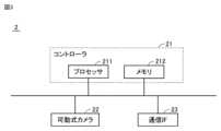
1 is a diagram illustrating an overall configuration of a vehicle photography system according to a first embodiment of the present disclosure. The
固定式カメラシステム1および可動式カメラシステム2は、たとえば、サーキットなどの道路近傍に設置され、当該道路を走行中の車両9(図5参照)を撮影する。図1では、固定式カメラシステム1および可動式カメラシステム2が1台ずつ示されているが、車両撮影システム100は、2以上の固定式カメラシステム1を備えてもよいし、2以上の可動式カメラシステム2を備えてもよい。The
サーバ3は、たとえば、車両撮影サービスを提供する事業者の自社サーバである。サーバ3は、クラウドサーバ管理会社が提供するクラウドサーバであってもよい。サーバ3は、固定式カメラシステム1および可動式カメラシステム2を用いて撮影された動画からユーザが鑑賞するための画像(以下、「鑑賞画像」とも記載する)を生成し、生成された鑑賞画像をユーザに提供する。鑑賞画像は、一般的には静止画であるが、短い動画であってもよい。ユーザは、多くの場合、車両9のドライバであるが、特に限定されない。The
図2は、固定式カメラシステム1の典型的なハードウェア構成を示すブロック図である。固定式カメラシステム1は、コントローラ11と、固定式カメラ12と、通信インターフェイス(IF)13とを備える。コントローラ11は、プロセッサ111と、メモリ112とを含む。固定式カメラシステム1の構成要素はバス等によって互いに接続されている。Figure 2 is a block diagram showing a typical hardware configuration of the
プロセッサ111は、固定式カメラシステム1の全体的な動作を制御する。メモリ112は、いずれも図示しないが、ROM(Read Only Memory)と、RAM(Random Access Memory)と、フラッシュメモリとを含む。メモリ112は、プロセッサ111により実行されるプログラム(オペレーティングシステムおよびアプリケーションプログラム)と、そのプログラムで使用されるデータ(マップ、テーブル、数式、パラメータなど)とを記憶する。また、メモリ112は、固定式カメラシステム1により撮影された動画を一時的に格納する。The
固定式カメラ12は、本実施の形態では、車両9に設けられたナンバープレートのナンバーを認識可能な動画(以下、「識別動画」とも記載する)を撮影する。固定式カメラ12は、偏光レンズ付の高感度タイプのカメラであることが好ましい。In this embodiment, the
通信IF13は、可動式カメラシステム2およびサーバ3との通信を行うためのインターフェイスである。通信IF13は、たとえば4G(Generation)または5Gに準拠する通信モジュールである。The
図3は、可動式カメラシステム2の典型的なハードウェア構成を示すブロック図である。可動式カメラシステム2は、固定式カメラ12に代えて可動式カメラ22を備える点において、固定式カメラシステム1(図2参照)と異なる。それ以外の構成は共通である。Figure 3 is a block diagram showing a typical hardware configuration of the
可動式カメラ22は、鑑賞画像の生成に用いられる動画(以下、「鑑賞動画」とも記載する)を撮影する。可動式カメラ22も固定式カメラ12と同様に、偏光レンズ付の高感度タイプのカメラであることが好ましい。The
なお、固定式カメラ12は、本開示に係る「第1のカメラ」に相当する。可動式カメラ22は、本開示に係る「第2のカメラ」に相当する。「第1のカメラ」が固定式であることは一例に過ぎず、「第1のカメラ」および「第2のカメラ」の両方が可動式であってもよい。The fixed
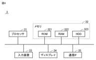
図4は、サーバ3の典型的なハードウェア構成を示すブロック図である。サーバ3は、プロセッサ31と、メモリ32と、入力装置33と、ディスプレイ34と、通信IF35とを備える。メモリ32は、ROM321と、RAM322と、HDD(Hard Disk Drive)323とを含む。サーバ3の構成要素はバス等によって互いに接続されている。Figure 4 is a block diagram showing a typical hardware configuration of the
プロセッサ31は、サーバ3における各種演算処理を実行する。メモリ32は、プロセッサ31により実行されるプログラムと、そのプログラムで使用されるデータとを記憶する。また、メモリ32は、サーバ3による画像処理に使用されるデータを格納したり、サーバ3により画像処理されたデータを格納したりする。入力装置33は、サーバ3の管理者の入力を受け付ける。入力装置33は、典型的にはキーボード、マウスである。ディスプレイ34は様々な情報を表示する。通信IF35は、固定式カメラシステム1および可動式カメラシステム2との通信を行うためのインターフェイスである。The
<車両撮影の様子>
図5は、実施の形態1における固定式カメラシステム1および可動式カメラシステム2による車両撮影の様子を示す第1の図(斜視図)である。図6は、実施の形態1における固定式カメラシステム1および可動式カメラシステム2による車両撮影の様子を示す第2の図(上面図)である。 <Vehicle photography>
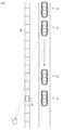
Fig. 5 is a first diagram (perspective view) showing how a vehicle is photographed by the fixed
図5および図6を参照して、実施の形態1では、固定式カメラシステム1(固定式カメラ12)は、ナンバープレートを撮影可能な方向から識別動画を撮影する。この例では、車両9のほぼ正面から識別動画が撮影される。Referring to Figures 5 and 6, in the first embodiment, the fixed camera system 1 (fixed camera 12) captures the identification video from a direction in which the license plate can be captured. In this example, the identification video is captured from approximately the front of the vehicle 9.
可動式カメラシステム2(可動式カメラ22)は、車両9を追従しながら、車両9がよく引き立つ(いわゆるSNS映えする)鑑賞動画を撮影する。この例では、可動式カメラシステム2はステージ801上に設置されている。これにより、可動式カメラシステム2は、回転可能(すなわち、撮影するアングルを変更可能)に構成されている。また、可動式カメラシステム2は、ステージ801上で高さを調整可能(後述するように、撮影するポジションを変更可能)に構成されている。The movable camera system 2 (movable camera 22) follows the vehicle 9 and shoots a viewing video that highlights the vehicle 9 (so-called social media-friendly video). In this example, the
図7は、識別動画の1フレームの一例を示す図である。図6および図7に示すように、識別動画には複数台の車両9(91,92)が写る場合がある。以下、複数台車両のうち撮影対象の車両(鑑賞画像を撮影しようとしている車両)を「対象車両」と記載し、それ以外の車両から区別する。Figure 7 is a diagram showing an example of one frame of an identification video. As shown in Figures 6 and 7, the identification video may show multiple vehicles 9 (91, 92). Hereinafter, the vehicle that is the subject of the shooting (the vehicle about to shoot the viewing image) among the multiple vehicles will be referred to as the "target vehicle" and will be distinguished from the other vehicles.
図8は、鑑賞動画の1フレームの一例を示す図である。この例では、対象車両である車両91は交差点を右折し、対象車両でない車両92は交差点を直進する。可動式カメラシステム2は、車両91の右折に伴って、撮影するポジション(垂直方向の高さ)およびアングル(水平方向に対してカメラを傾ける角度)を変更することによって、車両9が交差点を右折する様子の鑑賞動画を撮影する。Figure 8 is a diagram showing an example of one frame of a viewing video. In this example,
なお、鑑賞動画に関しては、対象車両(ここでは車両91)のナンバープレートが写っていることは要求されない。しかし、対象車両のナンバープレートが鑑賞動画に写っていてもよい。Note that the license plate of the target vehicle (
車両9(対象車両を含む)は、図5~図8に示したような四輪車に限られず、たとえば二輪車(バイク)であってもよい。二輪車のナンバープレートは後方にしか取り付けられていない。したがって、ナンバープレートを撮影できない状況が生じやすく、どの車両が対象車両かを特定しにくい。Vehicle 9 (including the target vehicle) is not limited to a four-wheeled vehicle as shown in Figures 5 to 8, but may be, for example, a two-wheeled vehicle (motorcycle). The license plate of a motorcycle is only attached to the rear. Therefore, it is easy to encounter a situation where the license plate cannot be photographed, making it difficult to identify which vehicle is the target vehicle.
<機能的構成>
図9は、実施の形態1における固定式カメラシステム1および可動式カメラシステム2の機能的構成を示す機能ブロック図である。固定式カメラシステム1は、撮影部41と、通信部42と、演算処理部43とを含む。演算処理部43は、車両抽出部431と、ナンバー認識部432と、マッチング処理部433と、対象車両選択部434と、特徴量抽出部435とを含む。 <Functional configuration>
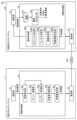
9 is a functional block diagram showing the functional configuration of the fixed
撮影部41は、ナンバー認識部432がナンバープレートのナンバーを認識可能な識別動画を撮影する。撮影部41は、識別動画を車両抽出部431に出力する。撮影部41は、図2の固定式カメラ12に対応する。The
通信部42は、ネットワークNWを介して可動式カメラシステム2の通信部51(後述)およびサーバ3の通信部62(後述)と双方向の通信を行う。通信部42は、サーバ3から対象車両のナンバーを受信する。また、通信部42は、識別動画から抽出された特徴量(後述)を可動式カメラシステム2およびサーバ3に送信する。通信部42は図2の通信IF13に対応する。The
車両抽出部431は、識別動画から車両(対象車両に限らず、車両全般)を抽出する。この処理を「車両抽出処理」とも記載する。車両抽出処理には、たとえば、ディープラーニング(深層学習)などの機械学習の技術により生成された学習済みモデルを用いることができる。車両抽出部431は、識別動画のうち車両が抽出された動画(車両を含むフレーム)をナンバー認識部432に出力するとともにマッチング処理部433に出力する。The
ナンバー認識部432は、車両抽出部431により車両が抽出された動画からナンバープレートのナンバーを認識する。この処理にもディープラーニングなどの機械学習の技術により生成された学習済みモデルを用いることができる。ナンバー認識部432は、認識したナンバーをマッチング処理部433に出力する。また、ナンバー認識部432は、認識したナンバーを通信部42に出力する。これにより、各車両のナンバーがサーバ3に送信される。The
マッチング処理部433は、車両抽出部431により抽出された車両と、ナンバー認識部432により認識されたナンバーとを対応付ける。この処理を「マッチング処理」とも記載する。具体的には、再び図7を参照して、2台の車両91,92が抽出され、かつ、2つのナンバー81,82が認識された状況を例に説明する。マッチング処理部433は、ナンバー毎に、ナンバーと車両との間の距離(フレーム上でのナンバーの座標と車両の座標との間の距離)を算出する。そして、マッチング処理部433は、ナンバーと、そのナンバーとの間の距離が短い車両とをマッチングする。この例では、ナンバー81と車両91との間の距離の方がナンバー81と車両92との間の距離よりも短いので、マッチング処理部433は、ナンバー81と車両91とを対応付ける。同様にして、マッチング処理部433は、ナンバー82と車両92とを対応付ける。マッチング処理部433は、マッチング処理の結果(ナンバーが対応付けられた車両)を対象車両選択部434に出力する。The matching
対象車両選択部434は、マッチング処理によってナンバーが対応付けられた車両のなかから、ナンバーが対象車両のナンバー(サーバ3から受信したもの)に一致する車両を対象車両として選択する。対象車両選択部434は、対象車両として選択された車両を特徴量抽出部435に出力する。The target
特徴量抽出部435は、対象車両を含む動画を解析することで対象車両の特徴量を抽出する。より具体的には、特徴量抽出部435は、対象車両の走行状態(走行位置、走行速度、走行方向など)を抽出したり、対象車両の外観(ボディ形状、ボディ色、ボディサイズなど)を抽出したりする。また、特徴量抽出部435は、対象車両の特徴量を通信部42に出力する。これにより、対象車両の特徴量が可動式カメラシステム2およびサーバ3に送信される。The
可動式カメラシステム2は、通信部51と、撮影部52と、演算処理部53とを含む。演算処理部53は、撮影制御部531と、動画バッファ532と、動画切り出し部533とを含む。The
通信部51は、ネットワークNWを介して固定式カメラシステム1の通信部42およびサーバ3の通信部62(後述)と双方向の通信を行う。通信部51は、固定式カメラシステム1から、識別動画から抽出された特徴量(後述)を受信する。また、通信部51は、可動式カメラシステム2により撮影された鑑賞動画をサーバ3に送信する。通信部51は図3の通信IF23に対応する。The
撮影部52は、撮影制御部531による制御に従って、鑑賞画像の生成に用いられる鑑賞動画を撮影する。撮影部52は、鑑賞動画を動画バッファ532に出力する。撮影部52は、図3の可動式カメラ22に対応する。The
撮影制御部531は、撮影部52の移動(可動式カメラ22の位置および速度)を制御する。撮影制御部531は、ポジション決定部531Aと、アングル決定部531Bと、回転速度決定部531Cと、サイズ調整部531Dとを含む。The
ポジション決定部531Aは、特徴量抽出部435により抽出された対象車両の走行位置、走行方向およびボディサイズに基づいて、可動式カメラ22により対象車両を撮影するポジション(高さ)を決定する。たとえば、ポジション決定部531Aは、対象車両が大型車両である場合には、対象車両が小型車両(二輪車など)である場合と比べて、ポジションを高くする。これにより、鑑賞動画中の対象車両の垂直方向の位置を適切な位置に設定できる。The
アングル決定部531Bは、特徴量抽出部435により抽出された対象車両の走行位置、走行方向およびボディサイズに基づいて、可動式カメラ22により対象車両を撮影するアングル(ローアングル、ハイアングルなど)を決定する。たとえば、対象車両が可動式カメラ22の近くで曲がる場合には、アングル決定部531Bは、(低いポジションから)ローアングルを選択して迫力および臨場感がある鑑賞動画を撮影できる。一方、対象車両が可動式カメラ22から遠ざかる方向に進行する場合には、アングル決定部531Bは、(高いポジションから)ハイアングルを選択して対象車両の走行の一連の様子を表す鑑賞動画を撮影できる。The
回転速度決定部531Cは、特徴量抽出部435により抽出された対象車両の走行位置および走行速度に基づいて、可動式カメラ22の回転速度を決定する。言い換えると、回転速度決定部531Cは、対象車両を追跡するように可動式カメラ22を制御する。回転速度決定部531Cは、対象車両の走行速度を事前に取得しておくことで、対象車両の鑑賞動画が撮影可能になる初期のタイミング(対象車両が可動式カメラ22の撮影範囲内に入ったタイミング)から適切な速度で可動式カメラ22を回転させて対象車両を追跡できる。The rotation
回転速度決定部531Cは、特徴量抽出部435により抽出された対象車両の外観(ボディサイズ、ボディ形状またはボディ色など)に基づいて、可動式カメラ22の回転速度を決定してもよい。回転速度決定部531Cは、対象車両の外観を事前に取得しておくことで、対象車両を他の車両から区別し、より正確に対象車両を追跡できる。The rotation
サイズ調整部531Dは、特徴量抽出部435により抽出された対象車両のボディサイズに基づいて、可動式カメラ22により対象車両を撮影するサイズ(ズーム倍率など)を調整する。これによっても、鑑賞動画中の対象車両を適切なサイズに設定できる。The
なお、撮影制御部531がポジション決定部531A、アングル決定部531B、回転速度決定部531Cおよびサイズ調整部531Dのうちのいずれか1つだけ、いずれか2つだけ、または、いずれか3つだけを含んでもよい。つまり、撮影制御部531は、特徴量抽出部435により抽出された特徴量に基づいて、可動式カメラ22の位置(ポジション)、向き(アングル)および速度(回転速度)のうちの1つまたは2つのみを決定してもよい。The
動画バッファ532は、鑑賞動画を一時的に記憶する。動画バッファ532は、代表的にはリングバッファ(循環バッファ)であって、1次元配列の先頭と末尾とが論理的に連結された環状の記憶領域を有する。新たに撮影された鑑賞動画は、記憶領域に格納可能な所定の時間分だけ動画バッファ532に記憶される。当該所定の時間を超えた分の古い鑑賞動画は、動画バッファ532から自動的に消去される。
動画切り出し部533は、動画バッファ532に記憶された鑑賞動画から、対象車両が撮影されるタイミングを含む所定の時間幅(たとえば数秒間~数十秒間)の動画を切り出す。動画切り出し部533は、切り出された鑑賞動画を通信部51に出力する。これにより、対象車両を含む鑑賞動画がサーバ3に送信される。なお、動画切り出し部533は、特徴量抽出部435により抽出された特徴量を用いて鑑賞動画中の対象動画を特定した上で、対象車両を含む鑑賞動画を切り出してもよい。The
図10は、サーバ3の機能的構成を示す機能ブロック図である。サーバ3は、記憶部61と、通信部62と、演算処理部63とを含む。記憶部61は、画像記憶部611と、登録情報記憶部612とを含む。演算処理部63は、車両抽出部631と、対象車両特定部632と、画像加工部633と、アルバム作成部634と、ウェブサービス管理部635と、カメラシステム管理部636とを含む。FIG. 10 is a functional block diagram showing the functional configuration of the
画像記憶部611は、サーバ3による演算処理の結果、得られる鑑賞画像を格納する。より具体的には、画像記憶部611は、画像加工部633による加工前後の画像を記憶するとともに、アルバム作成部634により作成されたアルバムを格納する。The
登録情報記憶部612は、車両撮影サービスに関する登録情報を記憶している。登録情報は、車両撮影サービスの提供を申し込んだユーザの個人情報と、そのユーザの車両情報とを含む。ユーザの個人情報は、たとえば、ユーザの識別番号(ID)、氏名、生年月日、住所、電話番号、メールアドレスなどに関する情報を含む。ユーザの車両情報は、車両のナンバープレートのナンバーに関する情報を含む。車両情報は、たとえば、車種、年式、ボディ形状(セダン型、ワゴン型、ワンボックス型など)、ボディ色、ボディサイズなどに関する情報をさらに含んでもよい。The registration
通信部62は、ネットワークNWを介して固定式カメラシステム1の通信部42および可動式カメラシステム2の通信部51(図9参照)と双方向の通信を行う。通信部62は、対象車両のナンバーを固定式カメラシステム1に送信する。また、通信部62は、固定式カメラシステム1から対象車両の特徴量を受信したり、可動式カメラシステム2から対象車両を含む鑑賞動画を受信したりする。通信部42は図4の通信IF35に対応する。The
車両抽出部631は、鑑賞動画から車両(対象車両に限らず、車両全般)を抽出する。この処理には、固定式カメラシステム1の車両抽出部431による車両抽出処理と同様に、学習済みモデルを用いることができる。車両抽出部631は、鑑賞動画のうち車両が抽出された動画(車両を含むフレーム)を対象車両特定部632に出力する。The
対象車両特定部632は、車両抽出部631により抽出された車両のなかから、対象車両の特徴量(すなわち、走行位置、走行速度、走行方向などの走行状態、および、ボディ形状、ボディ色、ボディサイズなどの外観)に基づいて対象車両を特定する。この処理にもディープラーニングなどの機械学習の技術により生成された学習済みモデルを用いることができる。対象車両特定部632によって対象車両が特定されることで鑑賞画像が生成される。鑑賞画像は、通常は複数の画像(時間的に連続した複数のフレーム)を含む。対象車両特定部632は、鑑賞画像を画像加工部633に出力する。The target
画像加工部633は鑑賞画像を加工する。たとえば、画像加工部633は、複数の画像のなかから最も写真映りがよい画像(いわゆるベストショット)を選択する。そして、画像加工部633は、選択された画像に対して様々な画像補正(トリミング、色補正、歪み補正など)を行う。画像加工部633は、加工済みの鑑賞画像をアルバム作成部634に出力する。The
アルバム作成部634は、加工済みの鑑賞画像を用いてアルバムを作成する。アルバム作成には公知の画像解析技術(たとえば、スマートホンで撮影された画像からフォトブック、スライドショーなどを自動で作成する技術)を用いることができる。アルバム作成部634は、アルバムをウェブサービス管理部635に出力する。The
ウェブサービス管理部635は、アルバム作成部634により作成されたアルバムを用いたウェブサービス(たとえばSNSに連携可能なアプリケーション)を提供する。これにより、ユーザは、作成されたアルバムを鑑賞したり、アルバム内の所望の画像をSNSに投稿したりすることができる。なお、ウェブサービス管理部635は、サーバ3とは別のサーバに実装されてもよい。The web
カメラシステム管理部636は、固定式カメラシステム1を管理(監視および診断)する。カメラシステム管理部636は、管理下の固定式カメラシステム1または可動式カメラシステム2に何らかの異常(カメラ故障、通信不具合など)が発生した場合に、そのことをサーバ3の管理者に通知する。これにより、管理者が該当のカメラシステムの点検、修理などの対応を取ることができる。カメラシステム管理部636もウェブサービス管理部635と同様に、別サーバとして実装され得る。The camera
<処理フロー>
図11は、本実施の形態における車両の撮影処理の処理手順を示すフローチャートである。このフローチャートは、たとえば予め定められた条件成立時または所定の周期毎に実行される。図中、左側に固定式カメラシステム1による処理を示し、中央に可動式カメラシステム2による処理を示し、右側にサーバ3による処理を示す。各ステップは、コントローラ11、コントローラ21またはプロセッサ31によるソフトウェア処理により実現されるが、ハードウェア(電気回路)により実現されてもよい。以下、ステップをSと略す。 <Processing flow>
11 is a flowchart showing the procedure of the vehicle photography process in this embodiment. This flowchart is executed, for example, when a predetermined condition is met or at a predetermined cycle. In the figure, the left side shows the process by the fixed
S11において、固定式カメラシステム1は、識別動画に対して車両抽出処理を実行することで車両を抽出する。さらに、固定式カメラシステム1は、車両が抽出された識別動画からナンバーを認識する(S12)。固定式カメラシステム1は、認識されたナンバーをサーバ3に送信する。In S11, the fixed
サーバ3は、固定式カメラシステム1からナンバーを受信すると、登録情報を参照することで、受信したナンバーが登録済みのナンバーであるかどうか(つまり、固定式カメラシステム1により撮影された車両が車両撮影サービスの提供を申し込んだユーザの車両(対象車両)であるかどうか)を判定する。受信したナンバーが登録済みのナンバー(対象車両のナンバー)である場合、サーバ3は、対象車両のナンバーを固定式カメラシステム1に送信するとともに、鑑賞動画を要求する(S31)。When the
S13において、固定式カメラシステム1は、認識動画における各車両と各ナンバーとのマッチング処理を実行する。そして、固定式カメラシステム1は、ナンバーが対応付けられた車両のなかから、対象車両のナンバーと同じナンバーが対応付けられた車両を対応車両として選択する(S14)。さらに、固定式カメラシステム1は、対象車両の特徴量(走行状態および外観)を抽出し、抽出された特徴量を可動式カメラシステム2およびサーバ3に送信する(S15)。In S13, the fixed
可動式カメラシステム2は、固定式カメラシステム1から特徴量を受信すると、可動式カメラ22の位置(ポジション)、向き(アングル)および速度(回転速度)を決定する(S21)。図9にて説明したように、可動式カメラシステム2は、対象車両の走行位置、走行方向、ボディサイズなどに基づいて、可動式カメラ22により対象車両を撮影するポジションおよびアングルを決定できる。可動式カメラシステム2は、対象車両の走行位置、走行速度および/または外観に基づいて、可動式カメラ22の回転速度を決定できる。可動式カメラシステム2は、対象車両のボディサイズに基づいて、可動式カメラ22により対象車両を撮影するサイズ(ズーム倍率など)を調整できる。When the
S22において、可動式カメラシステム2は、S21にて決定された位置、向きおよび速度で可動式カメラ22を制御しながら鑑賞画像を撮影する。そして、可動式カメラシステム2は、撮影された鑑賞動画のなかから対象車両を含む部分を切り出してサーバ3に送信する。In S22, the
S32において、サーバ3は、可動式カメラシステム2から受信した鑑賞動画に対して所定の処理を実行することで鑑賞画像を生成する。サーバ3による鑑賞画像生成のための処理については図10にて詳細に説明したため、説明は繰り返さない。In S32, the
以上のように、実施の形態1においては、2台のカメラシステム(固定式カメラシステム1および可動式カメラシステム2)が設けられている場合に、一方の固定式カメラシステム1により撮影された画像データ(識別動画)から抽出された特徴量に基づいて、もう一方の可動式カメラシステム2の位置(ポジション)、向き(アングル)および速度(回転速度)が決定される。固定式カメラシステム1による識別動画から抽出された特徴量を用いることによって、可動式カメラシステム2の位置、向きおよび速度を対象車両に応じて決定し、可動式カメラシステム2を適切に移動させることができる。As described above, in the first embodiment, when two camera systems (fixed
なお、本実施の形態では、固定式カメラシステム1と可動式カメラシステム2とが画像処理等の演算処理を分担して実行する例について説明した。この例では、固定式カメラシステム1のコントローラ11および可動式カメラシステム2のコントローラ21の両方が本開示に係る「コントローラ」に相当する。しかし、コントローラ11,21のうちのいずれか一方が演算処理を担当してもよい。また、当該演算処理の一部または全部を外部のサーバ3が担当してもよい。つまり、本開示に係る「コントローラ」の実体が固定式カメラシステム1にあるか可動式カメラシステム2にあるか外部(サーバ3)にあるかは特に限定されない。In this embodiment, an example has been described in which the fixed
[実施の形態2]
実施の形態1では、可動式カメラシステム2が回転可能に構成されている例について説明した。実施の形態2においては、可動式カメラシステム2が移動可能(並進可能)に構成されている例について説明する。 [Embodiment 2]
In the first embodiment, an example in which the
<車両撮影の様子>
図12は、実施の形態2における固定式カメラシステム1および可動式カメラシステム2による車両撮影の様子を示す第1の図(斜視図)である。図13は、実施の形態2における固定式カメラシステム1および可動式カメラシステム2による車両撮影の様子を示す第2の図(上面図)である。 <Vehicle photography>
Fig. 12 is a first diagram (perspective view) showing how a vehicle is photographed by the fixed
図12および図13を参照して、実施の形態2でも実施の形態1と同様に、固定式カメラシステム1は、ナンバープレートを撮影可能な方向(たとえば正面方向)から識別動画を撮影する。一方、可動式カメラシステム2Aはレール802上に設置されている。これにより、可動式カメラシステム2Aは、並進可能、すなわち、レール802上を移動しながら車両9の真横から鑑賞動画を撮影可能に構成されている。また、可動式カメラシステム2Aは、レール802上で高さ(ポジション)を調整可能に構成されている。Referring to Figures 12 and 13, in the second embodiment, as in the first embodiment, the fixed
なお、図12および図13には、道路に平行な方向に延在する1本の直線状のレール802が示されている。しかし、レール802の形状および本数は、撮影しようとする鑑賞動画に応じて適宜設定される。レール802は、道路に交わる方向に延在していてもよい。2以上のレール802が設置されていてもよい。また、レール802の設置自体が必須ではない。可動式カメラシステム2Aは、ラジコンカー、ドローンなどの移動体に設置されていてもよい。Note that Figures 12 and 13 show a single
<機能的構成>
図14は、実施の形態1における固定式カメラシステム1および可動式カメラシステム2Aの機能的構成を示す機能ブロック図である。固定式カメラシステム1は、実施の形態1における固定式カメラシステム1(図9参照)と同等である。可動式カメラシステム2Aは、撮影制御部531に代えて撮影制御部534を含む点において、実施の形態1における可動式カメラシステム2と異なる。撮影制御部534は、ポジション決定部534Aと、アングル決定部534Bと、距離決定部534Cと、移動速度決定部534Dとを含む。 <Functional configuration>
14 is a functional block diagram showing the functional configuration of the fixed
ポジション決定部534Aは、ポジション決定部531Aと同様に、特徴量抽出部435により抽出された対象車両の特徴量(たとえば走行位置、走行方向およびボディサイズ)に基づいて、可動式カメラ22により対象車両を撮影するポジション(高さ)を決定する。Similar to the
アングル決定部534Bは、アングル決定部531Bと同様に、特徴量抽出部435により抽出された対象車両の特徴量(たとえば走行位置、走行方向およびボディサイズ)に基づいて、可動式カメラ22により対象車両を撮影するアングル(ローアングル、ハイアングルなど)を決定する。Similar to the
距離決定部534Cは、特徴量抽出部435により抽出された対象車両の走行位置および走行方向に基づいて、可動式カメラ22により対象車両を撮影する距離(可動式カメラ22から対象車両までの距離)を決定する。たとえば、対象車両の走行経路が2以上に分かれている場合(対象車両が交差点に進入する場合など)に、複数の走行経路の各々に可動式カメラ22が設置されているときには、どの可動式カメラ22を用いて、どのような位置から対象車両を撮影するかを決定することが求められる。距離決定部534Cは、対象車両の走行位置および走行方向に基づいて、撮影に使用する可動式カメラ22を選択し、その可動式カメラ22をどの位置に移動させればよいかを決定する。距離決定部534Cは、たとえば、対象車両の走行位置に近く、かつ、対象車両の走行方向に移動可能な可動式カメラ22を選択し、その可動式カメラ22を対象車両の走行位置(走行推定位置であってもよい)の近くへと移動させる。これにより、対象車両に対して適切な距離に存在する可動式カメラ22を用いて対象車両を撮影できる。The
移動速度決定部534Dは、特徴量抽出部435により抽出された対象車両の走行速度に基づいて、可動式カメラ22の移動速度(並進速度)を決定する。言い換えると、移動速度決定部534Dは、対象車両を追跡(先導であってもよい)するように可動式カメラ22を制御する。移動速度決定部534Dは、対象車両の走行速度を事前に取得しておくことで、対象車両の鑑賞動画が撮影可能になる初期のタイミング(対象車両が可動式カメラ22の撮影範囲内に入ったタイミング)から適切な移動速度で可動式カメラ22を移動させて対象車両を追跡できる。The moving
移動速度決定部534Dは、特徴量抽出部435により抽出された対象車両の外観(ボディサイズ、ボディ形状またはボディ色など)に基づいて、可動式カメラ22の移動速度を決定してもよい。移動速度決定部534Dは、対象車両の外観を事前に取得しておくことで、対象車両を他の車両から区別し、より正確に対象車両を追跡できる。The movement
図示しないが、撮影制御部534がサイズ調整部(サイズ調整部531Dと同様のもの)を含んでもよい。これにより、可動式カメラ22により対象車両を撮影するサイズ(ズーム倍率など)を調整できる。Although not shown, the image
なお、撮影制御部534がポジション決定部534A、アングル決定部534B、距離決定部534Cおよび移動速度決定部534Dのうちのいずれか1つだけ、いずれか2つだけ、または、いずれか3つだけを含んでもよい。つまり、撮影制御部534は、特徴量抽出部435により抽出された特徴量に基づいて、可動式カメラ22の位置(ポジション、距離)、向き(アングル)および速度(移動速度)のうちの1つまたは2つのみを決定してもよい。The
実施の形態2における車両の撮影処理の処理手順を示すフローチャートは、実施の形態1における車両の撮影処理の処理手順を示すフローチャート(図11参照)と同様であるため、詳細な説明は繰り返さない。The flowchart showing the processing procedure for the vehicle image capture process in
以上のように、実施の形態2においては、2台のカメラシステム(固定式カメラシステム1および可動式カメラシステム2A)が設けられている場合に、一方の固定式カメラシステム1により撮影された画像データ(識別動画)から抽出された特徴量に基づいて、もう一方の可動式カメラシステム2Aの位置(ポジション、距離)、向き(アングル)および速度(移動速度)が決定される。固定式カメラシステム1による識別動画から抽出された特徴量を用いることによって、可動式カメラシステム2Aの位置、向きおよび速度を対象車両に応じて決定し、可動式カメラシステム2Aを適切に移動させることができる。As described above, in the second embodiment, when two camera systems (fixed
なお、実施の形態1,2では、識別動画に対するナンバー認識によって対象車両が選択されると説明したが、対象車両の選択手法はこれに限定されない。対象車両は、対象車両の通信情報(対象車両に搭載された通信機の識別情報)に基づいて選択されてもよいし、対象車両の位置情報(GPS(Global Positioning System)によって特定される対象車両の緯度および経度)に基づいて選択されてもよい。In the first and second embodiments, the target vehicle is selected by number recognition of the identification video, but the method of selecting the target vehicle is not limited to this. The target vehicle may be selected based on the communication information of the target vehicle (identification information of a communication device mounted on the target vehicle) or based on the location information of the target vehicle (latitude and longitude of the target vehicle identified by GPS (Global Positioning System)).
今回開示された実施の形態は、すべての点で例示であって制限的なものではないと考えられるべきである。本開示の範囲は、上記した実施の形態の説明ではなくて特許請求の範囲によって示され、特許請求の範囲と均等の意味および範囲内でのすべての変更が含まれることが意図される。The embodiments disclosed herein should be considered to be illustrative and not restrictive in all respects. The scope of the present disclosure is indicated by the claims rather than the description of the embodiments above, and is intended to include all modifications within the meaning and scope of the claims.
100 車両撮影システム、1 固定式カメラシステム、11 コントローラ、111 プロセッサ、112 メモリ、12 固定式カメラ、13 通信IF、2 可動式カメラシステム、21 コントローラ、211 プロセッサ、212 メモリ、22 可動式カメラ、23 通信IF、3 サーバ、31 プロセッサ、32 メモリ、321 ROM、322 RAM、323 HDD、33 入力装置、34 ディスプレイ、35 通信IF、41 撮影部、42 通信部、43 演算処理部、431 車両抽出部、432 ナンバー認識部、433 マッチング処理部、434 対象車両選択部、435 特徴量抽出部、51 通信部、52 撮影部、53 演算処理部、531,534 撮影制御部、531A,534A ポジション決定部、531B,534B ポジション決定部、531C 回転速度決定部、531D サイズ調整部、534C 距離決定部、534D 移動速度決定部、532 動画バッファ、533 動画切り出し部、61 記憶部、611 画像記憶部、612 登録情報記憶部、62 通信部、63 演算処理部、631 車両抽出部、632 対象車両特定部、633 画像加工部、634 アルバム作成部、635 ウェブサービス管理部、636 カメラシステム管理部、801 ステージ、802 レール、81,82 ナンバー、9,91,92 車両、NW ネットワーク。100 Vehicle photographing system, 1 Fixed camera system, 11 Controller, 111 Processor, 112 Memory, 12 Fixed camera, 13 Communication IF, 2 Movable camera system, 21 Controller, 211 Processor, 212 Memory, 22 Movable camera, 23 Communication IF, 3 Server, 31 Processor, 32 Memory, 321 ROM, 322 RAM, 323 HDD, 33 Input device, 34 Display, 35 Communication IF, 41 Photographing unit, 42 Communication unit, 43 Arithmetic processing unit, 431 Vehicle extraction unit, 432 Number recognition unit, 433 Matching processing unit, 434 Target vehicle selection unit, 435 Feature extraction unit, 51 Communication unit, 52 Photographing unit, 53 Arithmetic processing unit, 531, 534 Photographing control unit, 531A, 534A Position determination unit, 531B, 534B Position determination unit, 531C Rotation speed determination unit, 531D Size adjustment unit, 534C Distance determination unit, 534D Movement speed determination unit, 532 Video buffer, 533 Video extraction unit, 61 Storage unit, 611 Image storage unit, 612 Registration information storage unit, 62 Communication unit, 63 Calculation processing unit, 631 Vehicle extraction unit, 632 Target vehicle identification unit, 633 Image processing unit, 634 Album creation unit, 635 Web service management unit, 636 Camera system management unit, 801 Stage, 802 Rail, 81, 82 Number, 9, 91, 92 Vehicle, NW Network.
Claims (7)
Translated fromJapanese前記車両の走行中の様子を撮影可能な可動式の第2のカメラと、
前記第1および第2のカメラを制御するコントローラとを備え、
前記コントローラは、
前記第1のカメラにより撮影された画像データから、前記車両の走行位置および走行方向を含む前記車両の特徴量を抽出し、
前記車両の走行位置および走行方向に基づいて、前記第2のカメラの位置および向きを制御し、
前記第2のカメラの位置は、ハイポジションおよびローポジションを含み、
前記第2のカメラの向きは、ハイアングルおよびローアングルを含み、
前記コントローラは、
前記車両が前記第2のカメラの近くで曲がる場合には、前記ローポジションおよび前記ローアングルを選択する一方で、
前記車両が前記第2のカメラから遠ざかる方向に進行する場合には、前記ハイポジションおよび前記ハイアングルを選択する、車両撮影システム。 a first camera for photographing a vehicle;
a second movable camera capable of photographing the state of the vehicle while it is traveling;
a controller that controls the first and second cameras;
The controller:
extracting a feature amount of the vehicle including a traveling position and a traveling direction of the vehicle from image data captured by the first camera;
controlling a position and an orientation of the second camera based on a traveling position and a traveling direction of the vehicle;
the positions of the second camera include a high position and a low position;
the orientation of the second camera includes a high angle and a low angle;
The controller:
selecting the low position and the low angle when the vehicleturns near the second camera, while
A vehicle photographing system that selects the high position and the high angle when the vehicle travels in a direction away from the second camera.
前記車両のボディサイズを前記特徴量としてさらに抽出し、
前記車両のボディサイズに基づいて、前記第2のカメラの位置および向きのうちの少なくとも一方を制御する、請求項1に記載の車両撮影システム。 The controller:
A body size of the vehicle is further extracted as the feature amount;
The vehicle photographing system according to claim 1 , wherein at least one of a position and an orientation of the second camera is controlled based on a body size of the vehicle.
前記コントローラは、
前記車両の走行速度を前記特徴量としてさらに抽出し、
前記車両の走行速度に基づいて、前記第2のカメラの並進速度を制御する、請求項1に記載の車両撮影システム。 the second camera is configured to be translatable on a rail;
The controller:
A traveling speed of the vehicle is further extracted as the feature amount;
The vehicle photographing system according to claim 1 , further comprising: a translation speed of the second camera being controlled based on a traveling speed of the vehicle.
前記複数の第2のカメラは、
前記車両の走行方向に移動可能であり、かつ、前記車両の走行位置に近いカメラと、
前記車両の走行方向に移動可能であり、かつ、前記近いカメラと比べて、前記車両の走行位置から遠いカメラとを含み、
前記コントローラは、前記近いカメラおよび前記遠いカメラのうち、前記近いカメラが前記車両の走行位置に近付くように、前記近いカメラを制御する、請求項3に記載の車両撮影システム。 The vehicle photography system includes a plurality of the second cameras,
The plurality ofsecond cameras include
A camera that is movable in a traveling direction of the vehicle and is close to a traveling position of the vehicle;
a camera that is movable in a traveling direction of the vehicle and is farther from a traveling position of the vehicle than the closer camera;
The vehicle photographing system according to claim 3 , wherein the controller controls the closer camera out of the closer camera and the farther camera such that the closer camera approaches a traveling position of the vehicle.
前記車両のボディサイズ、ボディ形状またはボディ色を前記特徴量としてさらに抽出し、
前記車両のボディサイズ、ボディ形状またはボディ色に基づいて、前記第2のカメラの速度を制御する、請求項1に記載の車両撮影システム。 The controller:
Further extracting a body size, a body shape, or a body color of the vehicle as the feature amount;
The vehicle photographing system according to claim 1 , wherein the speed of the second camera is controlled based on a body size, a body shape, or a body color of the vehicle.
前記車両のボディサイズを前記特徴量としてさらに抽出し、
前記車両のボディサイズに基づいて、前記第2のカメラのズーム倍率をさらに制御する、請求項1に記載の車両撮影システム。 The controller:
A body size of the vehicle is further extracted as the feature amount;
The vehicle photographing system according to claim 1 , further comprising: a zoom magnification of the second camera being further controlled based on a body size of the vehicle.
第1のカメラにより撮影された画像データから、車両の走行位置および走行方向を含む前記車両の特徴量を抽出するステップと、
可動式の第2のカメラの位置および向きを、前記車両の走行位置および走行方向に基づいて制御するステップとを含み、
前記第2のカメラの位置は、ハイポジションおよびローポジションを含み、
前記第2のカメラの向きは、ハイアングルおよびローアングルを含み、
前記制御するステップは、
前記車両が前記第2のカメラの近くで曲がる場合には、前記ローポジションおよび前記ローアングルを選択するステップと、
前記車両が前記第2のカメラから遠ざかる方向に進行する場合には、前記ハイポジションおよび前記ハイアングルを選択するステップとを含む、車両撮影方法。 A method for photographing a vehicle by a computer, comprising:
extracting a feature amount of the vehicle including a traveling position and a traveling direction of the vehicle from image data captured by a first camera;
and controlling a position and an orientation of a movable second camera based on a traveling position and a traveling direction of the vehicle;
the positions of the second camera include a high position and a low position;
the orientation of the second camera includes a high angle and a low angle;
The controlling step includes:
selecting the low position and the low angle when the vehicleturns near the second camera;
and selecting the high position and the high angle when the vehicle travels in a direction away from the second camera.
Priority Applications (2)
| Application Number | Priority Date | Filing Date | Title |
|---|---|---|---|
| JP2021191867AJP7632248B2 (en) | 2021-11-26 | 2021-11-26 | Vehicle photographing system and vehicle photographing method |
| US17/969,057US12020457B2 (en) | 2021-11-26 | 2022-10-19 | Vehicle imaging system and vehicle imaging method |
Applications Claiming Priority (1)
| Application Number | Priority Date | Filing Date | Title |
|---|---|---|---|
| JP2021191867AJP7632248B2 (en) | 2021-11-26 | 2021-11-26 | Vehicle photographing system and vehicle photographing method |
Publications (2)
| Publication Number | Publication Date |
|---|---|
| JP2023078640A JP2023078640A (en) | 2023-06-07 |
| JP7632248B2true JP7632248B2 (en) | 2025-02-19 |
Family
ID=86500427
Family Applications (1)
| Application Number | Title | Priority Date | Filing Date |
|---|---|---|---|
| JP2021191867AActiveJP7632248B2 (en) | 2021-11-26 | 2021-11-26 | Vehicle photographing system and vehicle photographing method |
Country Status (2)
| Country | Link |
|---|---|
| US (1) | US12020457B2 (en) |
| JP (1) | JP7632248B2 (en) |
Families Citing this family (1)
| Publication number | Priority date | Publication date | Assignee | Title |
|---|---|---|---|---|
| JP2024097267A (en)* | 2023-01-05 | 2024-07-18 | キヤノン株式会社 | Imaging device, calibrator, and control method and program thereof |
Citations (3)
| Publication number | Priority date | Publication date | Assignee | Title |
|---|---|---|---|---|
| JP2004005206A (en) | 2002-05-31 | 2004-01-08 | Hanshin Expressway Public Corp | Road status photographing apparatus, traffic control equipment and traffic control method |
| JP2010140360A (en) | 2008-12-12 | 2010-06-24 | Mitsubishi Heavy Ind Ltd | Automatic toll reception device with camera for certificate |
| JP2019078880A (en) | 2017-10-24 | 2019-05-23 | キヤノン株式会社 | Control device, imaging apparatus, control method, and program |
Family Cites Families (45)
| Publication number | Priority date | Publication date | Assignee | Title |
|---|---|---|---|---|
| WO2005117440A2 (en)* | 2004-05-26 | 2005-12-08 | I-Track Ltd. | Surveillance means |
| JP4337929B2 (en)* | 2007-12-25 | 2009-09-30 | トヨタ自動車株式会社 | Moving state estimation device |
| DE112009001639T5 (en)* | 2008-07-07 | 2011-09-29 | Mitsubishi Electric Corporation | Vehicle traveling environment detection device |
| EP2469467A1 (en)* | 2010-12-23 | 2012-06-27 | Alcatel Lucent | An integrated method for camera planning and positioning |
| TWI450024B (en)* | 2012-06-05 | 2014-08-21 | Wistron Corp | 3-dimensional depth image generating system and method thereof |
| US9171382B2 (en)* | 2012-08-06 | 2015-10-27 | Cloudparc, Inc. | Tracking speeding violations and controlling use of parking spaces using cameras |
| US8967889B2 (en)* | 2013-04-26 | 2015-03-03 | Kessler Crane, Inc. | Panning slider |
| US20140376778A1 (en)* | 2013-06-25 | 2014-12-25 | Zf Friedrichshafen Ag | License plate recognition system and location forecasting |
| US9625084B2 (en)* | 2013-07-02 | 2017-04-18 | Camera Goat, LLC | System for mounting camera equipment |
| KR102016551B1 (en)* | 2014-01-24 | 2019-09-02 | 한화디펜스 주식회사 | Apparatus and method for estimating position |
| US9363357B2 (en)* | 2014-04-25 | 2016-06-07 | Mirsani, LLC | Detecting and reporting a vehicle of interest |
| US10867327B1 (en)* | 2014-06-27 | 2020-12-15 | Blinker, Inc. | System and method for electronic processing of vehicle transactions based on image detection of vehicle license plate |
| US10070077B2 (en)* | 2014-09-26 | 2018-09-04 | Sensormatic Electronics, LLC | System and method for automated camera guard tour operation |
| WO2016100601A2 (en)* | 2014-12-17 | 2016-06-23 | Picpocket, Inc. | Drone based systems and methodologies for capturing images |
| GB201507392D0 (en)* | 2015-04-30 | 2015-06-17 | Yearwood Clebert O R | Surveillance vehicle |
| SG10201505251XA (en)* | 2015-07-02 | 2017-02-27 | Nec Asia Pacific Pte Ltd | Surveillance System With Fixed Camera And Temporary Cameras |
| US9684993B2 (en)* | 2015-09-23 | 2017-06-20 | Lucasfilm Entertainment Company Ltd. | Flight path correction in virtual scenes |
| EP3416370B1 (en)* | 2016-03-23 | 2023-07-26 | Huawei Technologies Co., Ltd. | Photography focusing method, device, and apparatus for terminal |
| US10068377B2 (en)* | 2016-03-24 | 2018-09-04 | Toyota Jidosha Kabushiki Kaisha | Three dimensional graphical overlays for a three dimensional heads-up display unit of a vehicle |
| KR20170123907A (en)* | 2016-04-29 | 2017-11-09 | 엘지전자 주식회사 | Mobile terminal and method for controlling the same |
| US10645297B2 (en)* | 2016-09-30 | 2020-05-05 | Optim Corporation | System, method, and program for adjusting angle of camera |
| WO2018168565A1 (en)* | 2017-03-12 | 2018-09-20 | 株式会社ナイルワークス | Drone for capturing images of field crops |
| JP7091613B2 (en)* | 2017-07-05 | 2022-06-28 | ソニーグループ株式会社 | Imaging equipment, camera-mounted drones, and mode control methods, as well as programs |
| US10971011B2 (en)* | 2017-10-27 | 2021-04-06 | Toyota Jidosha Kabushiki Kaisha | Database creation apparatus, parking lot search apparatus, and database creation method |
| JP6922729B2 (en)* | 2017-12-26 | 2021-08-18 | トヨタ自動車株式会社 | Server equipment, car sharing system, information processing method, and information processing program |
| JP6950538B2 (en) | 2018-01-11 | 2021-10-13 | トヨタ自動車株式会社 | Vehicle photography support device and program |
| JP7128577B2 (en) | 2018-03-30 | 2022-08-31 | セコム株式会社 | monitoring device |
| US10867510B2 (en)* | 2018-04-05 | 2020-12-15 | Toyota Jidosha Kabushiki Kaisha | Real-time traffic monitoring with connected cars |
| JP2019200478A (en)* | 2018-05-14 | 2019-11-21 | トヨタ自動車株式会社 | Server, vehicle photographing system, and vehicle photographing method |
| JP6828719B2 (en)* | 2018-06-27 | 2021-02-10 | トヨタ自動車株式会社 | In-vehicle device and control method |
| JP7006527B2 (en)* | 2018-07-09 | 2022-01-24 | トヨタ自動車株式会社 | In-vehicle equipment and vehicle search system |
| JP7155750B2 (en)* | 2018-08-23 | 2022-10-19 | トヨタ自動車株式会社 | Information systems and programs |
| CN109271892A (en)* | 2018-08-30 | 2019-01-25 | 百度在线网络技术(北京)有限公司 | A kind of object identification method, device, equipment, vehicle and medium |
| US10817729B2 (en)* | 2018-09-26 | 2020-10-27 | Allstate Insurance Company | Dynamic driving metric output generation using computer vision methods |
| US10944900B1 (en)* | 2019-02-13 | 2021-03-09 | Intelligent Security Systems Corporation | Systems, devices, and methods for enabling camera adjustments |
| WO2020202756A1 (en)* | 2019-03-29 | 2020-10-08 | ソニー株式会社 | Information processing device, information processing method, and program |
| WO2020203126A1 (en)* | 2019-04-02 | 2020-10-08 | ソニー株式会社 | Information processing device, information processing method, and program |
| JP7442078B2 (en)* | 2019-07-09 | 2024-03-04 | パナソニックIpマネジメント株式会社 | Image processing device and image processing method |
| JP7176496B2 (en) | 2019-09-17 | 2022-11-22 | トヨタ自動車株式会社 | vehicle photography system |
| JP7171938B2 (en)* | 2019-09-27 | 2022-11-15 | 本田技研工業株式会社 | Imaging system, control device, control method, program and storage medium |
| US11184517B1 (en)* | 2020-06-26 | 2021-11-23 | At&T Intellectual Property I, L.P. | Facilitation of collaborative camera field of view mapping |
| US11460867B2 (en)* | 2020-06-30 | 2022-10-04 | Sony Group Corporation | System of multi-swarm drone capturing |
| US11070767B1 (en)* | 2020-10-09 | 2021-07-20 | Telecare LLC | Third witness video participation system and method |
| US20220124290A1 (en)* | 2020-10-15 | 2022-04-21 | Denso International America, Inc. | Systems and methods for monitoring a vehicle by collaboration of nearby devices |
| JP7533426B2 (en)* | 2021-11-18 | 2024-08-14 | トヨタ自動車株式会社 | Image processing system and image processing method |
- 2021
- 2021-11-26JPJP2021191867Apatent/JP7632248B2/enactiveActive
- 2022
- 2022-10-19USUS17/969,057patent/US12020457B2/enactiveActive
Patent Citations (3)
| Publication number | Priority date | Publication date | Assignee | Title |
|---|---|---|---|---|
| JP2004005206A (en) | 2002-05-31 | 2004-01-08 | Hanshin Expressway Public Corp | Road status photographing apparatus, traffic control equipment and traffic control method |
| JP2010140360A (en) | 2008-12-12 | 2010-06-24 | Mitsubishi Heavy Ind Ltd | Automatic toll reception device with camera for certificate |
| JP2019078880A (en) | 2017-10-24 | 2019-05-23 | キヤノン株式会社 | Control device, imaging apparatus, control method, and program |
Also Published As
| Publication number | Publication date |
|---|---|
| US12020457B2 (en) | 2024-06-25 |
| JP2023078640A (en) | 2023-06-07 |
| US20230169685A1 (en) | 2023-06-01 |
Similar Documents
| Publication | Publication Date | Title |
|---|---|---|
| JP4894712B2 (en) | Composition determination apparatus, composition determination method, and program | |
| EP3547212B1 (en) | An arrangement for generating head related transfer function filters | |
| CN105981368A (en) | Photo composition and position guidance in an imaging device | |
| KR102037997B1 (en) | Electronic apparatus and method for generating contents | |
| JP7632248B2 (en) | Vehicle photographing system and vehicle photographing method | |
| CN113688680A (en) | An intelligent identification and tracking system | |
| JP2007074143A (en) | Imaging apparatus and imaging system | |
| CN115170753A (en) | Three-dimensional modeling processing method based on unmanned aerial vehicle oblique photography | |
| CN115996322A (en) | Image data management method for digital video shooting | |
| US20190005982A1 (en) | Method and systemfor creating a comprehensive personal video clip | |
| CN113391644A (en) | Unmanned aerial vehicle shooting distance semi-automatic optimization method based on image information entropy | |
| CN106791456A (en) | A kind of photographic method and electronic equipment | |
| CN115376114B (en) | A method and system for multi-modal image framing of a car camera | |
| CN104978389B (en) | Method, system, server and client | |
| JP7533426B2 (en) | Image processing system and image processing method | |
| KR102628714B1 (en) | Photography system for surpporting to picture for mobile terminal and method thereof | |
| JP7739983B2 (en) | Image Processing System | |
| JP7533429B2 (en) | Image processing system and image processing method | |
| CN114140500A (en) | Target automatic detection and tracking method, device, computing device and storage medium | |
| US20230169768A1 (en) | Image processing system | |
| US20240412481A1 (en) | Image processing apparatus, image processing method, and program | |
| CN119228896B (en) | Positioning method, electronic device, computer-readable storage medium, and positioning system | |
| CN108259840A (en) | A kind of multi-channel video capture method and device for being suitable for mark platform | |
| JP2024094745A (en) | Image Processing System | |
| WO2025034130A1 (en) | Method for locking image capture frames and processing images |
Legal Events
| Date | Code | Title | Description |
|---|---|---|---|
| A621 | Written request for application examination | Free format text:JAPANESE INTERMEDIATE CODE: A621 Effective date:20231108 | |
| A977 | Report on retrieval | Free format text:JAPANESE INTERMEDIATE CODE: A971007 Effective date:20240816 | |
| A131 | Notification of reasons for refusal | Free format text:JAPANESE INTERMEDIATE CODE: A131 Effective date:20240820 | |
| A521 | Request for written amendment filed | Free format text:JAPANESE INTERMEDIATE CODE: A523 Effective date:20240918 | |
| A131 | Notification of reasons for refusal | Free format text:JAPANESE INTERMEDIATE CODE: A131 Effective date:20241112 | |
| A521 | Request for written amendment filed | Free format text:JAPANESE INTERMEDIATE CODE: A523 Effective date:20241125 | |
| TRDD | Decision of grant or rejection written | ||
| A01 | Written decision to grant a patent or to grant a registration (utility model) | Free format text:JAPANESE INTERMEDIATE CODE: A01 Effective date:20250107 | |
| A61 | First payment of annual fees (during grant procedure) | Free format text:JAPANESE INTERMEDIATE CODE: A61 Effective date:20250120 | |
| R150 | Certificate of patent or registration of utility model | Ref document number:7632248 Country of ref document:JP Free format text:JAPANESE INTERMEDIATE CODE: R150 |