JP7631310B2 - CSI reporting based on ternary codebooks - Google Patents
CSI reporting based on ternary codebooksDownload PDFInfo
- Publication number
- JP7631310B2 JP7631310B2JP2022509080AJP2022509080AJP7631310B2JP 7631310 B2JP7631310 B2JP 7631310B2JP 2022509080 AJP2022509080 AJP 2022509080AJP 2022509080 AJP2022509080 AJP 2022509080AJP 7631310 B2JP7631310 B2JP 7631310B2
- Authority
- JP
- Japan
- Prior art keywords
- csi
- basis
- layer
- subgroup
- index
- Prior art date
- Legal status (The legal status is an assumption and is not a legal conclusion. Google has not performed a legal analysis and makes no representation as to the accuracy of the status listed.)
- Active
Links
Images


Classifications
- H—ELECTRICITY
- H04—ELECTRIC COMMUNICATION TECHNIQUE
- H04B—TRANSMISSION
- H04B7/00—Radio transmission systems, i.e. using radiation field
- H04B7/02—Diversity systems; Multi-antenna system, i.e. transmission or reception using multiple antennas
- H04B7/04—Diversity systems; Multi-antenna system, i.e. transmission or reception using multiple antennas using two or more spaced independent antennas
- H04B7/06—Diversity systems; Multi-antenna system, i.e. transmission or reception using multiple antennas using two or more spaced independent antennas at the transmitting station
- H04B7/0613—Diversity systems; Multi-antenna system, i.e. transmission or reception using multiple antennas using two or more spaced independent antennas at the transmitting station using simultaneous transmission
- H04B7/0615—Diversity systems; Multi-antenna system, i.e. transmission or reception using multiple antennas using two or more spaced independent antennas at the transmitting station using simultaneous transmission of weighted versions of same signal
- H04B7/0619—Diversity systems; Multi-antenna system, i.e. transmission or reception using multiple antennas using two or more spaced independent antennas at the transmitting station using simultaneous transmission of weighted versions of same signal using feedback from receiving side
- H04B7/0621—Feedback content
- H04B7/0626—Channel coefficients, e.g. channel state information [CSI]
- H—ELECTRICITY
- H04—ELECTRIC COMMUNICATION TECHNIQUE
- H04B—TRANSMISSION
- H04B7/00—Radio transmission systems, i.e. using radiation field
- H04B7/02—Diversity systems; Multi-antenna system, i.e. transmission or reception using multiple antennas
- H04B7/04—Diversity systems; Multi-antenna system, i.e. transmission or reception using multiple antennas using two or more spaced independent antennas
- H04B7/0413—MIMO systems
- H04B7/0456—Selection of precoding matrices or codebooks, e.g. using matrices antenna weighting
- H04B7/0478—Special codebook structures directed to feedback optimisation
- H—ELECTRICITY
- H04—ELECTRIC COMMUNICATION TECHNIQUE
- H04B—TRANSMISSION
- H04B7/00—Radio transmission systems, i.e. using radiation field
- H04B7/02—Diversity systems; Multi-antenna system, i.e. transmission or reception using multiple antennas
- H04B7/04—Diversity systems; Multi-antenna system, i.e. transmission or reception using multiple antennas using two or more spaced independent antennas
- H04B7/06—Diversity systems; Multi-antenna system, i.e. transmission or reception using multiple antennas using two or more spaced independent antennas at the transmitting station
- H04B7/0613—Diversity systems; Multi-antenna system, i.e. transmission or reception using multiple antennas using two or more spaced independent antennas at the transmitting station using simultaneous transmission
- H04B7/0615—Diversity systems; Multi-antenna system, i.e. transmission or reception using multiple antennas using two or more spaced independent antennas at the transmitting station using simultaneous transmission of weighted versions of same signal
- H04B7/0619—Diversity systems; Multi-antenna system, i.e. transmission or reception using multiple antennas using two or more spaced independent antennas at the transmitting station using simultaneous transmission of weighted versions of same signal using feedback from receiving side
- H04B7/0621—Feedback content
- H04B7/063—Parameters other than those covered in groups H04B7/0623 - H04B7/0634, e.g. channel matrix rank or transmit mode selection
- H—ELECTRICITY
- H04—ELECTRIC COMMUNICATION TECHNIQUE
- H04B—TRANSMISSION
- H04B7/00—Radio transmission systems, i.e. using radiation field
- H04B7/02—Diversity systems; Multi-antenna system, i.e. transmission or reception using multiple antennas
- H04B7/04—Diversity systems; Multi-antenna system, i.e. transmission or reception using multiple antennas using two or more spaced independent antennas
- H04B7/06—Diversity systems; Multi-antenna system, i.e. transmission or reception using multiple antennas using two or more spaced independent antennas at the transmitting station
- H04B7/0613—Diversity systems; Multi-antenna system, i.e. transmission or reception using multiple antennas using two or more spaced independent antennas at the transmitting station using simultaneous transmission
- H04B7/0615—Diversity systems; Multi-antenna system, i.e. transmission or reception using multiple antennas using two or more spaced independent antennas at the transmitting station using simultaneous transmission of weighted versions of same signal
- H04B7/0619—Diversity systems; Multi-antenna system, i.e. transmission or reception using multiple antennas using two or more spaced independent antennas at the transmitting station using simultaneous transmission of weighted versions of same signal using feedback from receiving side
- H04B7/0636—Feedback format
- H04B7/0639—Using selective indices, e.g. of a codebook, e.g. pre-distortion matrix index [PMI] or for beam selection
- H—ELECTRICITY
- H04—ELECTRIC COMMUNICATION TECHNIQUE
- H04B—TRANSMISSION
- H04B7/00—Radio transmission systems, i.e. using radiation field
- H04B7/02—Diversity systems; Multi-antenna system, i.e. transmission or reception using multiple antennas
- H04B7/04—Diversity systems; Multi-antenna system, i.e. transmission or reception using multiple antennas using two or more spaced independent antennas
- H04B7/06—Diversity systems; Multi-antenna system, i.e. transmission or reception using multiple antennas using two or more spaced independent antennas at the transmitting station
- H04B7/0613—Diversity systems; Multi-antenna system, i.e. transmission or reception using multiple antennas using two or more spaced independent antennas at the transmitting station using simultaneous transmission
- H04B7/0615—Diversity systems; Multi-antenna system, i.e. transmission or reception using multiple antennas using two or more spaced independent antennas at the transmitting station using simultaneous transmission of weighted versions of same signal
- H04B7/0619—Diversity systems; Multi-antenna system, i.e. transmission or reception using multiple antennas using two or more spaced independent antennas at the transmitting station using simultaneous transmission of weighted versions of same signal using feedback from receiving side
- H04B7/0658—Feedback reduction
- H—ELECTRICITY
- H04—ELECTRIC COMMUNICATION TECHNIQUE
- H04L—TRANSMISSION OF DIGITAL INFORMATION, e.g. TELEGRAPHIC COMMUNICATION
- H04L1/00—Arrangements for detecting or preventing errors in the information received
- H04L1/0001—Systems modifying transmission characteristics according to link quality, e.g. power backoff
- H04L1/0023—Systems modifying transmission characteristics according to link quality, e.g. power backoff characterised by the signalling
- H04L1/0027—Scheduling of signalling, e.g. occurrence thereof
- H—ELECTRICITY
- H04—ELECTRIC COMMUNICATION TECHNIQUE
- H04L—TRANSMISSION OF DIGITAL INFORMATION, e.g. TELEGRAPHIC COMMUNICATION
- H04L5/00—Arrangements affording multiple use of the transmission path
- H04L5/0001—Arrangements for dividing the transmission path
- H04L5/0014—Three-dimensional division
- H04L5/0023—Time-frequency-space
- H—ELECTRICITY
- H04—ELECTRIC COMMUNICATION TECHNIQUE
- H04L—TRANSMISSION OF DIGITAL INFORMATION, e.g. TELEGRAPHIC COMMUNICATION
- H04L5/00—Arrangements affording multiple use of the transmission path
- H04L5/003—Arrangements for allocating sub-channels of the transmission path
- H04L5/0048—Allocation of pilot signals, i.e. of signals known to the receiver
- H—ELECTRICITY
- H04—ELECTRIC COMMUNICATION TECHNIQUE
- H04L—TRANSMISSION OF DIGITAL INFORMATION, e.g. TELEGRAPHIC COMMUNICATION
- H04L5/00—Arrangements affording multiple use of the transmission path
- H04L5/0091—Signalling for the administration of the divided path, e.g. signalling of configuration information
- H—ELECTRICITY
- H04—ELECTRIC COMMUNICATION TECHNIQUE
- H04B—TRANSMISSION
- H04B7/00—Radio transmission systems, i.e. using radiation field
- H04B7/02—Diversity systems; Multi-antenna system, i.e. transmission or reception using multiple antennas
- H04B7/10—Polarisation diversity; Directional diversity
- H—ELECTRICITY
- H04—ELECTRIC COMMUNICATION TECHNIQUE
- H04W—WIRELESS COMMUNICATION NETWORKS
- H04W72/00—Local resource management
- H04W72/20—Control channels or signalling for resource management
- H04W72/23—Control channels or signalling for resource management in the downlink direction of a wireless link, i.e. towards a terminal
Landscapes
- Engineering & Computer Science (AREA)
- Signal Processing (AREA)
- Computer Networks & Wireless Communication (AREA)
- Physics & Mathematics (AREA)
- Mathematical Physics (AREA)
- Quality & Reliability (AREA)
- Mobile Radio Communication Systems (AREA)
- Radio Transmission System (AREA)
Description
Translated fromJapanese本発明は、無線通信の分野に関し、特に、ユーザ機器から、無線通信システムにおいてチャネル状態情報(CSI)フィードバックを1つ又は複数のCSIリポートの形態で提供する方法、ユーザ機器、ネットワークノード、及びコンピュータプログラム製品に関する。The present invention relates to the field of wireless communications, and in particular to a method, user equipment, network node, and computer program product for providing channel state information (CSI) feedback in the form of one or more CSI reports from a user equipment in a wireless communications system.
3GPP第五世代無線通信システム又は略して5Gとも呼ばれるNew Radio等の無線通信システムでは、ダウンリンク(downlink : DL)信号及びアップリンク(uplink : UL)信号は、データ信号、DL制御情報(DL control information : DCI)及び/又はアップリンク制御情報(uplink control information : UCI)を含む制御信号、及び異なる目的で使用される幾つかの基準信号(reference signal : RS)を搬送する。無線ネットワークノード、又は無線基地局、又はgノードB(又はgNB又はgNB/TRP(Transmit Reception Point : 送信受信ポイント))は、いわゆる物理ダウンリンク共有チャネル(physical downlink shared channel : PDSCH)及び物理ダウンリンク制御チャネル(physical downlink control channel : PDCCH)を通してデータ及びDCIをそれぞれ送信する。In wireless communication systems such as 3GPP fifth generation wireless communication systems or New Radio, also called 5G for short, downlink (DL) and uplink (UL) signals carry data signals, control signals including DL control information (DCI) and/or uplink control information (UCI), and several reference signals (RS) used for different purposes. A radio network node, or radio base station, or gNode B (or gNB or gNB/TRP (Transmit Reception Point)) transmits data and DCI through the so-called physical downlink shared channel (PDSCH) and physical downlink control channel (PDCCH), respectively.
UEは、いわゆる物理アップリンク共有チャネル(physical uplink shared channel : PUSCH)及び物理アップリンク制御チャネル(physical uplink control channel : PUCCH)を通してデータ及びUCIをそれぞれ送信する。さらに、gNB、すなわちユーザ機器(user equipment : UE)又は無線デバイスのDL又はUL信号はそれぞれ、チャネル状態情報RS(channel state information RS : CSI-RS)、復調RS(demodulation RS : DM-RS)、及びサウンディングRS(sounding RS : SRS)を含む1つ又は複数のタイプのRSを含み得る。CSI-RS(SRS)は、DL(UL)システム帯域幅部分で送信され、CSI取得のためにUE(gNB)において使用される。DM-RSは、各PDSCH/PUSCHの帯域幅部分でのみ送信され、データ復調のためにUE/gNBによって使用される。The UE transmits data and UCI through the so-called physical uplink shared channel (PUSCH) and physical uplink control channel (PUCCH), respectively. Furthermore, the DL or UL signal of the gNB, i.e., user equipment (UE) or wireless device, may contain one or more types of RS, including channel state information RS (CSI-RS), demodulation RS (DM-RS), and sounding RS (SRS). CSI-RS (SRS) is transmitted in the DL (UL) system bandwidth portion and is used in the UE (gNB) for CSI acquisition. DM-RS is transmitted only in the bandwidth portion of each PDSCH/PUSCH and is used by the UE/gNB for data demodulation.
5Gの多くの主要特徴の1つは、前世代のモバイルシステムと比較して高いシステムスループットを達成するために多入力多出力(multi-input multi-output : MIMO)伝送方式を使用することである。MIMO伝送では一般に、データ及び制御情報のプリコーディング行列を使用して信号をプリコーディングするために、gNBで使用される正確なCSIの可用性が求められる。したがって、現在の第三世代パートナーシッププロジェクトリリース15仕様(3GPPリリース15)は、CSI報告の包括的な枠組みを提供している。CSIは、UEにおける第1のステップにおいて、gNBによって送信された受信CSI-RS信号に基づいて取得される。UEは第2のステップにおいて、推定されたチャネル行列に基づいて、「コードブック」と呼ばれる予め定義された行列セットからプリコーディング行列を決定する。第3のステップにおいて、選択されたプリコーディング行列は、プリコーディング行列識別子(precoding matrix identifier : PMI)及びランク識別子(rank identifier : RI)の形態でgNBに報告される。One of the many key features of 5G is the use of multiple-input multiple-output (MIMO) transmission schemes to achieve higher system throughput compared to previous generation mobile systems. MIMO transmissions generally require the availability of accurate CSI, which is used by the gNB to precode signals using precoding matrices for data and control information. Thus, the current Third Generation Partnership Project Release 15 specifications (3GPP Release 15) provide a comprehensive framework for CSI reporting. In a first step at the UE, the CSI is obtained based on the received CSI-RS signals transmitted by the gNB. In a second step, the UE determines a precoding matrix from a predefined set of matrices called a "codebook" based on the estimated channel matrix. In a third step, the selected precoding matrix is reported to the gNB in the form of a precoding matrix identifier (PMI) and a rank identifier (RI).
3GPPリリース15のデュアルステージプリコーディング及びCSI報告
現在のリリース15NR仕様では、CSI報告に2つのタイプ(タイプI及びタイプII)が存在し、両タイプともデュアルステージ、すなわち2成分W1W2コードブックに依拠する。第1の成分、すなわち第1ステージプリコーダW1は、ビームベクトルの数及び設定されている場合には回転オーバーサンプリングファクタ(rotation oversampling factors)を空間コードブックとも呼ばれる離散フーリエ変換ベース(Discrete Fourier Transform-based : DFTベース)の行列から選択するのに使用される。空間コードブックは、次元N1N2×N1O1N2O2のDFT又はオーバーサンプリングDFT行列を含み、O1及びO2はそれぞれコードブックの第1及び第2の次元に関するオーバーサンプリングファクタを示す。コードブックにおけるDFTベクトルは(q1,q2)、0≦q1≦O1-1、0≦q2≦O2-1サブグループにグループ化され、ここで、各サブグループはN1N2個のDFTベクトルを含み、パラメータq1及びq2は回転オーバーサンプリングファクタとして示される。第2の成分、いわゆる第2ステージプリコーダW2は、選択されたビームベクトルの結合に使用される。 Dual Stage Precoding and CSI Reporting in 3GPP Release 15 In the current Release 15NR specification, there are two types of CSI reporting (Type I and Type II), both of which rely on a dual stage, i.e., two-componentW1W2 codebook.The first component, i.e., the first stage precoderW1 , is used to select the number of beam vectors and, if configured, rotation oversampling factors from a Discrete Fourier Transform-based (DFT -based)matrix , also called the spatial codebook. The spatial codebook contains a DFT or oversampling DFT matrix of dimensionsN1N2xN1O1N2O2 ,whereO1 andO2 denote the oversampling factors for the first and second dimensions of the codebook, respectively. The DFT vectors in the codebook are grouped into (q1 , q2 ), 0≦q1 ≦O1 −1, 0≦q2 ≦O2 −1 subgroups, where each subgroup contains N1 N2 DFT vectors, and the parameters q1 and q2 are denoted as rotational oversampling factors. The second component, the so-called second stage precoder W2 , is used to combine the selected beam vectors.
構成(N1,N2,2)を有するgNBにおけるランクR伝送及びデュアル偏波アンテナアレイを仮定すると、s番目のサブバンド及びr番目の送信層について[1](非特許文献1)に開示されるリリース15ダブルステージプリコーダは、 Assuming rank-R transmission and a dual-polarized antenna array in a gNB with configuration (N1 , N2 , 2), the Release 15 double-stage precoder disclosed in [1] for the s th subband and the r th transmission layer is
によって与えられ、プリコーダ行列W(r)(s)は、アンテナポート数に対応する2N1N2行及び報告サブバンド/PRBのS列を有する。行列
where the precoder matrix W(r) (s) has 2N1 N2 rows corresponding to the number of antenna ports and S columns of reporting subbands/PRBs.
は全てのS個のサブバンドで同一である両偏波で2U個の空間ビームを含むワイドバンド第1ステージプリコーダであり、FAは、2U個の空間ビームと関連付けられた2U個のワイドバンド振幅を含む対角行列であり、
is a wideband first stage precoder containing 2U spatial beams in both polarizations that are identical for all S subbands,F is a diagonal matrix containing 2U wideband amplitudes associated with the 2U spatial beams,
は、2U個のサブバンド、サブバンド振幅及び位相、s番目のサブバンドの2U個の空間ビームと関連付けられた複素周波数領域結合係数を含む第2ステージプリコーダである。
is the second stage precoder that contains 2U subbands, subband amplitudes and phases, and complex frequency-domain combining coefficients associated with the 2U spatial beams of the sth subband.
3GPPリリース15のデュアルステージタイプIIのCSI報告では、第2ステージプリコーダW2は、 In the 3GPP Release 15 dual stage Type II CSI report, the second stage precoderW2 is
の列の数が、設定されたサブバンドの数に依存するようにサブバンドベースで計算される。ここで、サブバンドは隣接する物理的リソースブロック(physical resource block : PRB)のグループを指す。タイプIIのCSIフィードバックの1つの主な欠点は、結合係数をサブバンドベースで報告するためのフィードバックオーバーヘッドが大きいことである。フィードバックオーバーヘッドは、サブバンド数に伴って概ね線形に増え、サブバンドが多数の場合、かなり大きくなる。リリース15タイプIIのCSI報告方式の高フィードバックオーバーヘッドを解消するために、最近、3GPP RAN#81[2](非特許文献2)(3GPP無線アクセスネットワーク(RAN)3GPP RAN#81)において、第2ステージプリコーダW2のフィードバック圧縮方式を研究することが決定された。幾つかの寄稿[3]及び[4](非特許文献3,4)では、小さなDFT基底ベクトルセットを使用するW2を遅延領域に変換する場合、W2におけるビーム結合係数の数が劇的に低下し得ることが実証された。対応する3ステージプリコーダは、3ステージ、即ち3成分
is calculated on a subband basis such that the number of columns of depends on the number of configured subbands. Here, a subband refers to a group of adjacent physical resource blocks (PRBs). One major drawback of Type-II CSI feedback is the large feedback overhead for reporting combining coefficients on a subband basis. The feedback overhead grows approximately linearly with the number of subbands, and can become quite large for a large number of subbands. To address the high feedback overhead of the Release-15 Type-II CSI reporting scheme, it was recently decided to investigate feedback compression schemes for the second stage precoderW2 in 3GPP RAN#81 [2] (3GPP Radio Access Network (RAN) 3GPP RAN#81). Several contributions [3] and [4] have demonstrated that the number of beam combining coefficients inW2 can be dramatically reduced when transformingW2 using a small set of DFT basis vectors to the delay domain. The corresponding three-stage precoder has three stages, i.e., three components.
コードブックに依拠する。行列W1によって表される第1の成分は、リリース15NRの成分と同一であり、層(r)から独立し、空間コードブックから選択される幾つかの空間領域(spatial domain : SD)基底ベクトルを含む。行列W3(r)によって表される第2の成分は、層依存であり、遅延コードブックとも呼ばれる離散フーリエ変換ベース(Discrete Fourier Transform-based : DFTベース)の行列から幾つかの遅延領域(delay domain : DD)基底ベクトルを選択するのに使用される。行列W2(r)によって表される第3の成分は層依存であり、空間及び遅延コードブックからそれぞれ選択されたSD基底ベクトル及びDD基底ベクトルを結合するのに使用される結合係数の数を含む。
The first component, represented by matrixW1 , is identical to that of Release 15NR, is independent of the layer (r), and contains some spatial domain (SD) basis vectors selected from the spatial codebook. The second component, represented by matrixW3(r) , is layer-dependent and is used to select some delay domain (DD) basis vectors from a Discrete Fourier Transform-based (DFT-based) matrix, also called delay codebook. The third component, represented by matrixW2(r) , is layer-dependent and contains the number of combining coefficients used to combine the SD and DD basis vectors selected from the spatial and delay codebooks, respectively.
ランクR伝送を仮定すると、2N1N2構成のアンテナ/DL-RSポート及びN3構成のサブバンドの3成分プリコーダ行列又はCSI行列は、アンテナポートの第1の偏波及びr番目の送信層について Assuming rank R transmission, the ternary precoder matrix or CSI matrix for 2N1 N2 antenna/DL-RS ports and N3 subbands is given by
として表され、アンテナポートの第2の偏波及びr番目の送信層について
for the second polarization of the antenna port and the r-th transmission layer:
として表され、式中、bu=(u=0,・・・,U-1)は空間コードブックから選択されるu番目のSD基底ベクトルを表し、
where bu =(u=0, . . . , U−1) represents the u th SD basis vector selected from the spatial codebook;
は遅延コードブックから選択されるr番目の層と関連付けられたd番目のDD基底ベクトルであり、γ(p,u,d)(r)は、u番目のSD基底ベクトル、d番目のDD基底ベクトル、及びp番目の偏波と関連付けられた複素遅延領域結合係数であり、Uは設定されたSD基底ベクトルの数を表し、Dは設定されたDD基底ベクトルの数を表し、α(l,p)は正規化スカラーである。
is the dth DD basis vector associated with the rth layer selected from the delay codebook, γ(p,u,d)(r) is the complex delay-domain coupling coefficient associated with the uth SD basis vector, the dth DD basis vector, and the pth polarization, U represents the number of SD basis vectors set, D represents the number of DD basis vectors set, and α(l,p) is a normalization scalar.
式(2)における3成分CSI報告方式の主な利点は、プリコーダ行列又はCSI行列の結合係数を報告するフィードバックオーバーヘッドがもはや、設定される周波数領域サブバンドの数に依存しないことであり、即ちシステム帯域幅から独立することである。さらに、プリコーダ行列又はCSI行列のフィードバックオーバーヘッド及び性能は、層ごとに又は全ての層で、第3の成分W2(r)に含めることができ、UEによって報告される最大数の非ゼロ結合係数KをUEに設定することにより、gNBによって制御することができる。非ゼロ結合係数の振幅及び位相情報のみが報告されるため、層ごとの2UD個の係数の何れかがUEによって選択され報告されるかを示すビットマップ等のインジケータが必要とされる。[5](非特許文献5)によれば、r番目の層の選択された非ゼロ係数がビットマップによって示され、ここで、ビットマップ中の各ビットは偏波インデックス(p∈{1,2})、SD基底インデックス(0≦u≦U-1)、及びDD基底インデックス(0≦d≦D-1)と関連付けられる。ビットマップ中の「1」は、偏波インデックスp、SD基底インデックスu、及びDD基底インデックスと関連付けられた結合係数が非ゼロであり、UEによって選択され報告されることを示す。ビットマップ中の「0」は、偏波インデックスp、SD基底ベクトルu、及びDD基底インデックスdと関連付けられる結合係数がゼロであることを示し、したがって、UEによって報告されない結合係数であることを示す。 The main advantage of the three-component CSI reporting scheme in equation (2) is that the feedback overhead of reporting the combining coefficients of the precoder matrix or the CSI matrix is no longer dependent on the number of frequency domain subbands configured, i.e., it is independent of the system bandwidth. Furthermore, the feedback overhead and performance of the precoder matrix or the CSI matrix can be included in the third component W2(r) for each layer or for all layers, and can be controlled by the gNB by configuring the maximum number of non-zero combining coefficients K reported by the UE. Since only the amplitude and phase information of the non-zero combining coefficients is reported, an indicator such as a bitmap is needed to indicate which of the 2UD coefficients per layer is selected and reported by the UE. According to [5], the selected non-zero coefficients of the rth layer are indicated by a bitmap, where each bit in the bitmap is associated with a polarization index (p∈{1,2}), an SD basis index (0≦u≦U-1), and a DD basis index (0≦d≦D-1). A "1" in the bitmap indicates that the combining coefficients associated with the polarization index p, SD basis index u, and DD basis index are non-zero and are selected and reported by the UE. A "0" in the bitmap indicates that the combining coefficients associated with the polarization index p, SD basis vector u, and DD basis index d are zero and therefore are not reported by the UE.
[6](非特許文献6)によれば、層ごとの最強結合係数は1に正規化され、報告されない。層の2UD個の係数の何れかが最強結合係数であるかを示すために、最強係数インジケータ(strongest coefficient indicator : SCI)が層ごとにUEによって報告される。According to [6], the strongest coupling coefficient for each layer is normalized to 1 and is not reported. A strongest coefficient indicator (SCI) is reported by the UE for each layer to indicate which of the 2UD coefficients of a layer is the strongest coupling coefficient.
[6](非特許文献6)によれば、非ゼロ結合係数γ(p,u,d)(r)(W2(r)に含まれる)は以下: According to [6], the non-zero coupling coefficient γ(p,u,d)(r) (included in W2(r)) is given by:
として量子化され、式中、結合係数の振幅γ(p,u,d)(r)は2つの振幅、即ちPref(r,p)及びa(p,u,d)(r)によってそれぞれ示される第1及び第2の振幅によって与えられる。ここで、Pref(r,p)は、偏波p(p=1,2)と関連付けられた全ての振幅値に共通する各偏波に定義される偏波基準振幅を示す。Uの偏波インデックスでは、SCI(Pref(r,p)=1)と関連付けられたSD成分は報告されない。他の偏波Pref(p’),p’≠pと関連付けられた偏波基準振幅はa’ビットを用いて量子化される。加えて、各結合係数γ(p,u,d)(r)の振幅a(p,u,d)(r)及び位相θ(p,u,d)(r)はそれぞれaビット及びbビットを用いて量子化される。
where the amplitude γ(p,u,d)(r) of the coupling coefficient is given by two amplitudes, namely the first and second amplitudes denoted by Pref(r,p) and a(p,u,d)(r) , respectively. Here, Pref(r,p) denotes the polarization reference amplitude defined for each polarization common to all amplitude values associated with polarization p (p=1,2). For a polarization index of U, the SD components associated with SCI (Pref(r,p) =1) are not reported. The polarization reference amplitudes associated with the other polarizations Pref(p') , p'≠p are quantized using a' bits. In addition, the amplitude a(p,u,d)(r) and phase θ(p,u,d)(r) of each coupling coefficient γ(p,u,d)(r) are quantized using a and b bits, respectively.
3成分CSI方式の構成及び報告
プリコーダ行列又はCSI行列の構成について、CSIリポート構成は、gNBからUEに上位層(例えばRRC)を介してシグナリングされ得、上位層CSIリポート構成は以下の情報を含み得る[7](非特許文献7):
- W1の計算のために空間コードブックからUEによって選択すべきSD基底ベクトルの数を示すパラメータU、
- W3(r)の計算のために遅延コードブックから層ごとにUEによって選択すべきDD基底ベクトルの数を示すパラメータD又はそのバリアント(variants)、
- 層ごと又は全ての層で行列W2(r)に含まれ、選択されたSD基底ベクトルとDD基底ベクトルとを結合するのにUEによって使用される非ゼロ係数の最大数を示すパラメータK又はそのバリアント、
- CSI行列の周波数領域サブバンドの数及び遅延コードブック内のDD基底ベクトルの次元を示すパラメータN3、並びに
- DD基底ベクトルの報告構成の追加のパラメータ。 Configuration and reporting of three-component CSI scheme For the configuration of the precoder matrix or CSI matrix, the CSI reporting configuration may be signaled from the gNB to the UE via higher layers (e.g., RRC), and the higher layer CSI reporting configuration may include the following information [7]:
- A parameter U indicating the number of SD basis vectors to be selected by the UE from the spatial codebook for the computation ofW1 ;
A parameter D or its variants indicating the number of DD basis vectors to be selected by the UE per layer from the delay codebook for the computation of W3(r) ;
A parameter K or a variant thereof indicating the maximum number of non-zero coefficients included in the matrix W2(r) for each layer or for all layers and used by the UE to combine the selected SD and DD basis vectors;
- a parameterN3 indicating the number of frequency domain subbands of the CSI matrix and the dimension of the DD basis vectors in the delay codebook, and - an additional parameter for the reporting configuration of the DD basis vectors.
CSIリポートは少なくとも、CSI行列の層の選択された数を示すランクインジケータ(rank indicator : RI)と、全ての層KNZにわたる非ゼロ結合係数の選択された数の数と、CSI行列の3つの成分を定義するPMIとを含み得、PMIは少なくとも以下の情報を含む[7](非特許文献7):
- CSI行列のRI層の空間コードブックから選択されたU個のSD基底ベクトルと、設定されている場合、選択されたオーバーサンプリング回転ファクタ(oversampling rotation factors)を示す空間領域サブセットインジケータ(spatial domain subset indicator : SD基底インジケータ)、
- 層ごとの選択されたDD基底ベクトルを示す遅延領域サブセットインジケータ(delay domain subset indicator : DD基底インジケータ)、
- 報告されない、最強結合係数と関連付けられたSD基底インデックス又はSD及びDD基底インデックスを示す層ごとの最強係数インジケータ(strongest coefficient indicator : SCI)、
- 層ごとのKNZ,r個の選択された非ゼロ量子化遅延領域結合係数と関連付けられた振幅及び位相情報、
- 層ごとのKNZ,r個の非ゼロ係数と関連付けられたSD基底インデックス及びDD基底インデックスを示す層ごとのビットマップ、
- 層ごとの偏波固有基準振幅、並びに
- DD基底サブセット指示と関連付けられた追加の可能性があるパラメータ。 The CSI report may include at least a rank indicator (RI) indicating a selected number of layers of the CSI matrix, a selected number of non-zero coupling coefficients across all layers KNZ , and a PMI defining three components of the CSI matrix, where the PMI includes at least the following information [7]:
a spatial domain subset indicator (SD basis indicator) indicating U SD basis vectors selected from the spatial codebook of the RI layer of the CSI matrix and, if set, the selected oversampling rotation factors;
- delay domain subset indicators indicating the selected DD basis vectors for each layer;
- a layer-wise strongest coefficient indicator (SCI) indicating the SD basis index or the SD and DD basis index associated with the strongest combination coefficient, which is not reported;
Amplitude and phase information associated with KNZ,r selected non-zero quantized delay domain coupling coefficients per layer,
- KNZ for each layer, a bitmap indicating the SD and DD basis indices associated with the r non-zero coefficients;
- Polarization specific reference amplitudes per layer, as well as - additional possible parameters associated with the DD basis subset indication.
3GPPリリース15のCSI報告のUCI省略
PUSCHベースのリソース割り振り及びCSI報告でのUCI省略[1](非特許文献1)が3GPPリリース15で導入された。それにより、UEは、PUSCHリソース割り振りがCSIリポートの内容全体を搬送するのに十分ではない場合、1つ又は複数のCSIリポートの幾つかの部分をドロップすることができる。UCI省略は、CSIリポートのスケジュール時、基地局がPUSCHリソースを正確に割り振らなかった場合、行われ得る。例えば、基地局は、ランク1(RI=1)CSIリポートにリソースを割り振り得るが、UEはランク2送信を決定し、割り振られたPUSCHリソースのサイズよりも大きなサイズのランク2(RI=2)CSIリポートを報告する。そのような場合、UEはUCI内容の一部をドロップする必要がある。3GPPリリース15では、ドロップは、CSIリポートと関連付けられたUCIペイロードをより小さな複数の部分、いわゆる複数の優先度レベルに分解することによって達成される。[1](非特許文献1)の表5.2.3-1参照。この表では、優先度レベル0は最高優先度を有し、NREPは、PUSCH上で搬送されるように設定されたCSIリポートの総数を表す。各優先度レベルはCSIリポートの部分と関連付けられる。UEは、CSIリポートのペイロードサイズがPUSCHリソース割り振りと一致するように、優先度の低いCSI部分をドロップする。さらに、CSIペイロードは2つの部分:CSI部分1及びCSI部分2に分割される。CSI部分1は、RIと、CSI部分2のサイズを示すインジケータと、を含む。CSI部分1のサイズは固定され、一方、CSI部分2のサイズは、UEによって決定されたRI及び幾つかの他のファクタに応じて様々である。gNBは、CSI部分2を復号化するためにCSI部分1を知る必要があるため、UCI省略はCSI部分2に対してのみ実行される。 UCI Omission in CSI Reporting in 3GPP Release 15 PUSCH-based resource allocation and UCI omission in CSI reporting [1] was introduced in 3GPP Release 15. It allows the UE to drop some parts of one or more CSI reports if the PUSCH resource allocation is not sufficient to carry the entire content of the CSI report. UCI omission can occur if the base station does not correctly allocate PUSCH resources when scheduling the CSI report. For example, the base station may allocate resources for a rank-1 (RI=1) CSI report, but the UE decides on rank-2 transmission and reports a rank-2 (RI=2) CSI report with a size larger than the size of the allocated PUSCH resource. In such a case, the UE needs to drop some of the UCI content. In 3GPP Release 15, dropping is achieved by breaking down the UCI payload associated with a CSI report into smaller parts, so-called priority levels, see Table 5.2.3-1 in [1]. In this table,
CSI部分2は、2NREP+1個のCSI部分で作られる。ここで、2NREP個のCSI部分、いわゆるサブバンドPMIは、NREP個のCSIリポートの偶数及び奇数のサブバンドと関連付けられたCSI内容を含む。さらに、各サブバンドPMIは、インデックス1から始まる2NREPまでの優先度レベルと関連付けられる。加えて、優先度レベルインデックス0と関連付けられた第1のCSI部分は、全ての2NREP個のサブバンドPMI、即ちCSI報告帯域全体の情報を含む。リリース15のサブバンドベースのCSI分解及び省略法の背後にある動機は、CSIリポートnの第1のサブバンドPMIを省略する場合、gNBがCSIリポートnの報告された第2のサブバンドPMIのCSI内容を使用し、補間方式を使用することにより、省略された第1のサブバンドPMIのCSIを推定し得ることである。このようにして、隣のサブバンドは典型的には高度に相関するため、性能の深刻な低下を回避することができる。
既知の3成分CSI報告方式について、サブバンドベースのPMIは存在せず、CSI部分2を幾つかのサブバンドPMIに分解することは可能ではないため、3GPPリリース15のUCI省略手順は再使用することができない。したがって、新しいUCI省略ルールが必要とされる。For known 3-component CSI reporting schemes, the UCI omission procedure of 3GPP Release 15 cannot be reused since there is no subband-based PMI and it is not possible to decompose
なお、3成分CSI報告方式では、CSIリポートのCSIペイロードは、報告すべき非ゼロ係数の数によってUEにより制御することができる。UCI省略の場合、UEは単に、利用可能なPUSCHリソースに基づいて、CSIリポートの1つ又は複数で報告すべき非ゼロ係数の数を少なくし得る。しかしながら、非ゼロ結合係数の数を低減するには、結合係数、1つ又は複数のCSIリポートのCSI行列のSD及びDD基底ベクトルの再計算が必要であり、追加のUEリソースを占有する。そのような追加のUEリソースは、UEでは利用可能ではない。したがって、UCI省略方式は、1つ又は複数のCSIリポートのCSI行列の再計算を必要とすべきではない。Note that in a three-component CSI reporting scheme, the CSI payload of a CSI report can be controlled by the UE by the number of non-zero coefficients to be reported. In the case of UCI omission, the UE may simply reduce the number of non-zero coefficients to be reported in one or more of the CSI reports based on the available PUSCH resources. However, reducing the number of non-zero combining coefficients requires recalculation of combining coefficients, SD and DD basis vectors of the CSI matrix of one or more CSI reports, occupying additional UE resources. Such additional UE resources are not available to the UE. Therefore, the UCI omission scheme should not require recalculation of the CSI matrix of one or more CSI reports.
3成分CSI報告方式では、CSIリポートのペイロードのサイズは主に、CSIリポートの報告される非ゼロ結合係数のビットマップ並びに振幅及び位相情報によって決まる。In a three-component CSI reporting scheme, the size of the payload of the CSI report is determined primarily by the bitmap of reported non-zero coupling coefficients and the amplitude and phase information of the CSI report.
本発明では、3成分CSI報告方式でのCSIリポートの報告される非ゼロ結合係数のビットマップ並びに振幅及び位相情報の異なるセグメント化方式が提案される。
本発明の一解決策では、UCI省略方式は、CSIリポートの非ゼロ結合係数の振幅及び位相情報の一部をドロップすることに基づく。 In this invention, a different segmentation scheme of the bitmap and amplitude and phase information of the reported non-zero coupling coefficients of the CSI report in the 3-component CSI reporting scheme is proposed.
In one solution of the present invention, the UCI omission scheme is based on dropping part of the amplitude and phase information of the non-zero coupling coefficients of the CSI report.
本発明の別の解決策では、UCI省略方式は、非ゼロ結合係数の振幅及び/又は位相情報の一部と、ドロップされた結合係数と関連付けられたビットマップの一部とをドロップすることに基づく。In another solution of the invention, the UCI omission scheme is based on dropping part of the amplitude and/or phase information of the non-zero coupling coefficients and part of the bitmap associated with the dropped coupling coefficients.
本発明は、無線通信システムにおいて1つ又は複数のチャネル状態情報(CSI)リポートの形態でCSIフィードバックを提供するユーザ機器(UE)によって実行される方法を提供し、本方法は、
- MIMOチャネルを介してネットワークノード(gNB)から、1つ又は複数のダウンリンク基準信号の上位層構成、ダウンリンク基準信号の構成と関連付けられた1つ又は複数のCSIリポート構成、及び無線信号を受信することであって、無線信号は、1つ又は複数のダウンリンク基準信号の構成に従ったダウンリンク基準信号を含む、受信すること、
- 受信した1つ又は複数のダウンリンク基準信号に関する測定に基づいて、ダウンリンクMIMOチャネルを推定することであって、ダウンリンク基準信号は、設定された数の周波数領域リソース、時間領域リソース、及び1つ又は複数のポートを介して供給される、推定すること、
- 各CSIリポート構成について、推定されたチャネル行列と、2つのコードブックであって、
- プリコーダの1つ又は複数の空間領域(SD)基底成分を含む空間コードブック、及び
- プリコーダの1つ又は複数の遅延領域(DD)基底成分を含む遅延コードブックを含む2つのコードブックと、1つ又は複数のSD及びDD基底ベクトルを複素結合する1つ又は複数の非ゼロ結合係数と、に基づいて、プリコーディング行列を決定すること、
- ネットワークノードに、1つ又は複数のCSIリポート構成の1つ又は複数のCSIリポートを報告すること、を備える。 The present invention provides a method performed by a user equipment (UE) for providing channel state information (CSI) feedback in the form of one or more CSI reports in a wireless communication system, the method comprising:
receiving, from a network node (gNB) via a MIMO channel, higher layer configurations of one or more downlink reference signals, one or more CSI report configurations associated with the downlink reference signal configurations, and a wireless signal, the wireless signal including a downlink reference signal in accordance with the one or more downlink reference signal configurations;
- estimating a downlink MIMO channel based on measurements on one or more received downlink reference signals, the downlink reference signals being provided via a configured number of frequency domain resources, time domain resources and one or more ports;
For each CSI report configuration, an estimated channel matrix and two codebooks,
determining a precoding matrix based on two codebooks including a spatial codebook comprising one or more spatial-domain (SD) basis components of the precoder, and a delay codebook comprising one or more delay-domain (DD) basis components of the precoder, and one or more non-zero combining coefficients complex-combining the one or more SD and DD basis vectors;
reporting one or more CSI reports of one or more CSI report configurations to a network node.
各CSIリポートは、プリコーディング行列識別子(PMI)及びランク識別子(RI)の形態で、選択されたプリコーディング行列を含み、ランク識別子(RI)は、プリコーディング行列のRI層の送信ランクを示し、各CSIリポートはCSI部分1及びCSI部分2の2つの部分を含み、CSI部分1は固定されたペイロードサイズを有し、CSI部分2のペイロードのサイズを示す情報を含む。CSI部分2は少なくとも、選択された非ゼロ結合係数の振幅及び位相情報と、CSIリポートの非ゼロ結合係数を示す全てのRI層のビットマップとを含み、各層のビットマップは、選択されたDD基底ベクトルのDD基底インデックスに関してD個のビットシーケンスにセグメント化される。各ビットシーケンスは、2U個の空間ビームと関連付けられた2U×1ビットを含み、Uは空間コードブックから選択されたSD基底ベクトルの数を示し、各DD基底インデックスは遅延コードブックからの遅延ベクトルと関連付けられ、D個のビットシーケンスは、N3個のDD基底インデックスの2つの順序付け方式の一方に関して順序付けられ、ここでN3は遅延コードブックのDD基底インデックスの数を示し、N3個のDD基底インデックスは、第1の順序付け方式にしたがって0,1,N3-1,2,N3-2,3,N3-3,4,N3-4,5,・・・として順序付けられ、又はN3個のDD基底インデックスは、第2の順序付け方式にしたがって0,N3-1,1,N3-2,2,N3-3,3,N3-4,4,N3-5,5,・・・として順序付けられる。結合係数の振幅及び位相情報の順序付けは、全てのRI層のビットマップのビットシーケンスの順序に従う。CSI部分2の一部又は全体は、CSIリポートからの省略に利用可能である。 Each CSI report includes a selected precoding matrix in the form of a precoding matrix identifier (PMI) and a rank identifier (RI), where the rank identifier (RI) indicates the transmission rank of the RI layer of the precoding matrix, and each CSI report includes two parts,
本発明の提案される一態様によれば、CSI部分1は少なくとも、全てのRI層にわたる非ゼロ結合係数の選択された数についての情報と、選択されたプリコーディング行列のRI層の送信ランクの指示と、を含む。According to one proposed aspect of the present invention,
CSI部分2は少なくとも、選択されたプリコーディング行列のRI層についての以下の情報:
- 空間コードブックからの選択されたSD基底ベクトルを示す回転オーバーサンプリングファクタが設定される場合、回転オーバーサンプリングファクタを含む空間領域(SD)基底サブセットインジケータ、
- 遅延コードブックからの選択されたDD基底ベクトルを示す1つ又は複数の遅延領域(DD)基底サブセットインジケータ、
- 選択された非ゼロ遅延領域結合係数の位相及び振幅、
- 層ごとの最強係数と関連付けられたDD及びSDベクトルを示す最強係数インジケータSCI、
- 層ごとの偏波基準振幅、
- 層ごとの非ゼロ結合係数を示すビットマップ、並びに
- DD基底サブセット指示と関連付けられた追加の可能性があるパラメータ
を含むことも提案される。
A spatial domain (SD) basis subset indicator containing the rotational oversampling factor if a rotational oversampling factor is set, indicating the selected SD basis vector from the spatial codebook;
- one or more delay-domain (DD) basis subset indicators indicating selected DD basis vectors from a delay codebook;
the phase and amplitude of the selected non-zero delay region coupling coefficients,
- Strongest Coefficient Indicator SCI indicating the DD and SD vectors associated with the strongest coefficient per layer,
- Polarization reference amplitudes per layer,
It is also proposed to include: a bitmap indicating the non-zero connection coefficients per layer; and additional possible parameters associated with the DD basis subset indication.
本発明の別の態様は、NREP個のCSIリポートのCSI部分2は、TNREP+1個のCSIサブグループにセグメント化することができ、T個のCSIサブグループは常に、単一のCSIリポートと関連付けられ、1つのCSIサブグループは全てのNREP個のCSIリポートと関連付けられた情報を含み、各CSIサブグループは優先度、即ち優先度レベルと関連付けられることを教示する。 Another aspect of the present invention teaches that the
全てのNREP個のCSIリポートと関連付けられた情報を含むCSIサブグループは、最高優先度、即ち優先度レベル0を有し得、残りのTNREP個のCSIサブグループは、より低い優先度レベル1からTNREPまでと関連付けられ得、最後のCSIサブグループTNREPは最低優先度レベルTNREPと関連付けられることが提案される。 It is proposed that the CSI subgroup containing information associated with all NREP CSI reports may have the highest priority, i.e.
CSIサブグループは以下:
優先度0:CSIリポート1~NREPの部分2のジョイントCSIサブグループ
優先度1:CSIリポート1の部分2のCSIサブグループ1
・・・
優先度T:CSIリポート1の部分2のCSIサブグループT
優先度T+1:CSIリポート2の部分2のCSIサブグループ1
優先度2T:CSIリポート2の部分2のCSIサブグループT
・・・
優先度T(NREP-1)+1:CSIリポートNREPの部分2のCSIサブグループ1
・・・
優先度TNREP:CSIリポートNREPの部分2のCSIサブグループT
に従った優先度を有し得ることも提案される。 The CSI subgroups are:
Priority 0: Joint CSI Subgroup of
...
Priority T: CSI subgroup T of
Priority T+1:
Priority 2T: CSI subgroup T of
...
Priority T(NREP -1)+1:
...
Priority TNREP : CSI subgroup T of
It is also proposed that the priority order may be according to:
省略の場合、UEは、CSIリポートのペイロードサイズがgNBからのリソース割り振りと一致するまで、優先度がより低いCSIサブグループをドロップし得ることが提案される。特定の優先度レベルのCSIサブグループを省略する場合、UEはその優先度レベルの全てのCSI内容を省略し得る。In case of omission, it is proposed that the UE may drop CSI subgroups with lower priority until the payload size of the CSI report matches the resource allocation from the gNB. When omitting a CSI subgroup of a particular priority level, the UE may omit all CSI content of that priority level.
パラメータTは、CSIリポートごとのCSIサブグループの数を示し得、CSIリポートから省略されたCSI内容の粒度に関連し得、高値のTは高粒度を示し、低値のTは低粒度を示し、パラメータTに「2」の値が与えられる場合、各CSIリポートは2つのCSIサブグループのみと関連付けられる。The parameter T may indicate the number of CSI subgroups per CSI report and may relate to the granularity of the CSI content omitted from the CSI report, with a high value of T indicating high granularity and a low value of T indicating low granularity, such that if the parameter T is given a value of "2", each CSI report is associated with only two CSI subgroups.
本発明の提案される一態様は、ジョイントCSIサブグループと呼ばれる最初のCSIサブグループは、優先度レベル0と関連付けられ、全てのNREP個のCSIリポートのCSI情報を含み、ジョイントCSIサブグループは、以下のパラメータ:
- 回転オーバーサンプリングファクタが設定される場合、回転オーバーサンプリングファクタを含む選択されたSD基底サブセットインジケータ及び
- RI層のSCI
の少なくとも1つの情報を含むことを教示する。 A proposed aspect of the present invention is that a first CSI subgroup, called the joint CSI subgroup, is associated with
- selected SD basis subset indicator including the rotational oversampling factor if a rotational oversampling factor is set; and - SCI for the RI layer
The present invention teaches that the information includes at least one of the following:
CSIリポートの最高優先度を有するCSIサブグループは少なくとも、以下のパラメータ:
- RI層の選択されたDD基底サブセットインジケータ、
- RI層の偏波基準振幅値、
- RI層のKNZ個の非ゼロ結合係数を示すビットマップ、及び
- DD基底サブセット指示と関連付けられた追加の可能性があるパラメータ
の情報を含むことも提案される。 The CSI sub-group with the highest priority for CSI reporting has at least the following parameters:
- selected DD basis subset indicator of the RI layer,
- the polarization reference amplitude value of the RI layer,
It is also proposed to include information of additional possible parameters associated with the DD basis subset indication; and a bitmap indicating the KNZ non-zero coupling coefficients of the RI layer.
本発明の提案される一態様は、CSIリポートの最高優先度を有するCSIサブグループは少なくとも、以下のパラメータ:
- RI層の選択されたDD基底サブセットインジケータ、
- RI層の偏波基準振幅値、
- RI層のKNZ個の非ゼロ結合係数を示すビットマップ、及び
- 窓パラメータMinit
の情報を含むことを教示する。 One proposed aspect of the present invention is that the CSI subgroup with the highest priority for CSI reporting comprises at least the following parameters:
- selected DD basis subset indicator of the RI layer,
- the polarization reference amplitude value of the RI layer,
- a bitmap indicating the KNZ non-zero coupling coefficients of the RI layer, and - a window parameter Minit
The information contained herein is intended to be accurate and up to date.
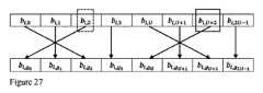
RI層の対応する順序付きビットマップは、サイズ2UD×RIのビットマップに一緒にグループ化され得、D個のセグメントにセグメント化され得、各セグメントはサイズ2U×RIを有し、d番目のセグメントは、全てのRI層の2U個のSDと関連付けられることも提案される。It is also proposed that the corresponding ordered bitmaps of the RI layers may be grouped together into a bitmap of size 2UD×RI and segmented into D segments, each segment having size 2U×RI, with the dth segment being associated with 2U SDs of all RI layers.
全ての層の同じSD基底インデックスと関連付けられたビットセグメント中のビットは一緒にグループ化され得、層インデックスの増大に関してソートされ得、第1のSD基底インデックスと関連付けられたRIビットは一緒にグループ化され得、第2のSD基底インデックスと関連付けられたRIビットが続き得、以降は同様になっていることが提案される。It is proposed that bits in a bit segment associated with the same SD base index for all layers may be grouped together and sorted with respect to increasing layer index, with the RI bits associated with the first SD base index being grouped together, followed by the RI bits associated with the second SD base index, and so on.
本発明の別の態様は、第2の順序付け方式にしたがって層ごとにDD基底インデックスを順序付けることは、式:Another aspect of the present invention is that ordering the DD basis indexes for each layer according to the second ordering scheme is expressed as the formula:
によって実現され得、式中、l=1,2,・・・,ν、f=0,1,・・・,D-1であり、
where l=1, 2, ..., v, f=0, 1, ..., D-1,
は各層のD個のDD基底インデックスからのf番目のDD基底インデックスであり、νは層の総数であることである。
is the fth DD basis index from the D DD basis indexes of each layer, and v is the total number of layers.
本発明のさらに別の態様は、ビットマップ中のビットの順序付けは、式:Yet another aspect of the present invention is that the ordering of bits in a bitmap is based on the formula:
によって実現し得、式中、
This can be achieved by:
であり、l=1,2,・・・,ν、i=0,1,・・・,2U-1、f=0,1,・・・,D-1であり、ここでνは層の総数であり、Uは偏波ごとの選択されたSD基底ベクトルの数であり、DはDD基底インデックスの数であることである。
, where l = 1, 2, ..., v, i = 0, 1, ..., 2U-1, and f = 0, 1, ..., D-1, where v is the total number of layers, U is the number of selected SD basis vectors per polarization, and D is the number of DD basis indices.
本発明の別の態様は、最高優先度を有するCSIサブグループの第1のセグメントは、DD基底ベクトルインデックス0と関連付け得ることである。
本発明の別の態様は、UEは、CSIリポートについて、インデックス0を有するDD基底ベクトルがSCIと関連付けられるようにSCIと関連付けられたDD基底ベクトルに関して、選択された結合係数及び層ごとに選択されるDD基底ベクトルに対して循環シフト演算を実行するように設定され得ることである。 Another aspect of the present invention is that the first segment of the CSI subgroup having the highest priority may be associated with DD
Another aspect of the present invention is that for a CSI report, the UE may be configured to perform a circular shift operation on the DD basis vectors selected for the selected combining coefficients and layer with respect to the DD basis vectors associated with the SCI such that the DD basis vector with
これは、CSIリポートごとに最高優先度を有するCSIサブグループが、選択された非ゼロ遅延領域結合係数の振幅及び位相値の第1の部分の情報を含み得、優先度のより低い残りのT-1個のCSIサブグループは、CSIリポートの振幅及び位相値の残りの部分を含み得ることを意味する。This means that the CSI subgroup with the highest priority per CSI report may contain information of the first portion of the amplitude and phase values of the selected non-zero delay region combining coefficients, and the remaining T-1 CSI subgroups of lower priority may contain the remaining portions of the amplitude and phase values of the CSI report.
最高優先度を有し、単一のCSIリポートと関連付けられた各CSIサブグループは、RI層のビットマップの少なくとも一部と、KNZ個の非ゼロ結合係数の部分の位相及び振幅情報とを含み得ることも提案される。 It is also proposed that each CSI subgroup having the highest priority and associated with a single CSI report may contain at least a portion of the RI layer bitmap and phase and amplitude information of a portion of the KNZ non-zero coupling coefficients.
これは、最高優先度を有するCSIサブグループが、
RI=ν層のビットマップの This means that the CSI subgroup with the highest priority is
RI = ν layer bitmap
個の最高優先度要素と、
highest priority elements; and
個の最高優先度振幅値と、
highest priority amplitude values;
個の最高優先度位相値と、を含み得ることを意味する。
単一のCSIリポートと関連付けられた各CSIサブグループは、RI層のビットマップの一部と関連付けられた結合係数の振幅及び位相情報を含み得ることも提案される。
highest priority phase values.
It is also proposed that each CSI sub-group associated with a single CSI report may contain amplitude and phase information of coupling coefficients associated with a portion of the RI layer bitmap.
単一のCSIリポートと関連付けられた最高優先度を有する各CSIサブグループは少なくとも、ビットマップの一部分及びRI層のSCIのDD基底ベクトルインデックスと関連付けられた結合係数の情報を含み得ることが提案される。It is proposed that each CSI subgroup with the highest priority associated with a single CSI report may contain at least a portion of the bitmap and coupling coefficient information associated with the DD basis vector index of the SCI of the RI layer.
最高優先度を有し、単一のCSIリポートと関連付けられた各CSIサブグループは少なくとも、CSIリポートで示されるプリコーディング行列のRI層についての1つ又は複数のDD基底ベクトルインデックスと関連付けられたビットマップを含み得、CSIサブグループは、ビットマップと関連付けられた結合係数の対応する振幅及び/又は位相情報を含み得ることも提案される。It is also proposed that each CSI subgroup having the highest priority and associated with a single CSI report may include at least a bitmap associated with one or more DD basis vector indices for the RI layer of the precoding matrix indicated in the CSI report, and that the CSI subgroup may include corresponding amplitude and/or phase information of the combining coefficients associated with the bitmap.
結合係数の一部分の情報を含む各CSIサブグループは、CSIリポートのEach CSI subgroup containing information on a portion of the coupling coefficients is
個の結合係数の最大と関連付けられた位相及び振幅値を含み得、優先度のより低い残りのCSIサブグループは、CSIリポートの残りの位相及び振幅値を含み得ることが提案される。
It is proposed that the CSI subgroup of lower priority may include the phase and amplitude values associated with the largest of the combining coefficients, and the remaining CSI subgroup of lower priority may include the remaining phase and amplitude values of the CSI report.
次いで、CSIリポートごとで最高優先度を有するCSIサブグループは、Then, the CSI subgroup with the highest priority per CSI report is
個の最高優先度振幅値及び
the highest priority amplitude values and
個の最高優先度位相値を含み得、最低優先度を有するCSIサブグループは、
the CSI subgroup having the lowest priority may include the highest priority phase values,
個の最低優先度振幅値及び
the lowest priority amplitude values and
個の最低優先度位相値を含み得ることが提案される。
本発明の別の態様は、結合係数の位相及び振幅値は、T=2且つx=2の場合、2つのCSIサブグループにセグメント化し得、第1のCSIサブグループは、
It is proposed that the metric may include the lowest priority phase values.
Another aspect of the invention is that the phase and amplitude values of the combining coefficients may be segmented into two CSI subgroups, where T=2 and x=2, and the first CSI subgroup is
個の結合係数と関連付けられた位相及び振幅値を含み、第2のCSIサブグループは、CSIリポートの残りの
the second CSI subgroup includes phase and amplitude values associated with the coupling coefficients, and the second CSI subgroup includes the remaining CSI report
個の結合係数と関連付けられた位相及び振幅を含むことを提案する。
CSIサブグループの結合係数の振幅及び位相情報は、X個の結合係数の振幅情報(Xaビット)の後に、X個の結合係数の位相情報(Xbビット)が続くように順序付けられ得ることが提案される。
We propose to include phases and amplitudes associated with the coupling coefficients.
It is proposed that the amplitude and phase information of the combining coefficients of the CSI subgroups may be ordered such that the amplitude information of the X combining coefficients (Xa bits) is followed by the phase information of the X combining coefficients (Xb bits).
次いで、CSIリポートごとで最高優先度を有するCSIサブグループについて、振幅値と関連付けられたThen, for the CSI subgroup with the highest priority per CSI report, an amplitude value is associated
最高優先度ビットの後に、位相値と関連付けられた
After the highest priority bit, there is a phase value associated with
最高優先度ビットが続き得、νは送信層の総数であることが提案される。
CSIリポートごとの最低優先度を有するCSIサブグループについて、振幅値と関連付けられた
It is proposed that the highest priority bit may follow, where v is the total number of transmission tiers.
For the CSI subgroup with the lowest priority per CSI report, an amplitude value associated with
最高優先度ビットの後に、位相値と関連付けられた
After the highest priority bit, there is a phase value associated with
最高優先度ビットが続き得、νは送信層の総数であることも可能である。
単一のCSIリポート及び最高優先度と関連付けられたCSIサブグループのビット幅は固定され得、A+Bによって与えられ、Aは、非ゼロ結合係数の数から離れたCSIサブグループに含まれる全ての成分の結合ビット幅であり、Bは、結合係数
The highest priority bit may follow, and v may be the total number of transmission tiers.
The bit width of a single CSI report and the CSI subgroup associated with the highest priority may be fixed and is given by A+B, where A is the combined bit width of all components included in the CSI subgroup apart from the number of non-zero combining coefficients, and B is the combining coefficient.
の一部分の振幅情報(a)及び位相情報(b)と関連付けられたビット幅である。
本発明は、無線通信システムにおいて1つ又は複数のチャネル状態情報(CSI)リポートの形態のCSIフィードバックを受信するネットワークノード(gNB)によって実行される方法にも関し、本方法は、
- MIMOチャネルを介してユーザ機器(UE)に、1つ又は複数のダウンリンク基準信号の上位層構成、ダウンリンク基準信号の構成と関連付けられた1つ又は複数のCSIリポート構成、及び無線信号を送信することであって、無線信号は、1つ又は複数のダウンリンク基準信号の構成に従ったダウンリンク基準信号を含む、送信すること、
- UEから、1つ又は複数のCSIリポート構成の1つ又は複数のCSIリポートを受信すること、を備え、1つ又は複数のCSIリポートは、UEが、
- 受信した1つ又は複数のダウンリンク基準信号に関する測定に基づいて、ダウンリンクMIMOチャネルを推定することであって、ダウンリンク基準信号は、設定された数の周波数領域リソース、時間領域リソース、及び1つ又は複数のポートを介して提供される、推定すること、
- 各CSIリポートについて、推定されたチャネルと、2つのコードブックであって、
- プリコーダの1つ又は複数の空間領域(SD)基底成分を含む空間コードブック、及び
- プリコーダの1つ又は複数の遅延領域(DD)基底成分を含む遅延コードブックを含む、2つのコードブックと、1つ又は複数のSD及びDD基底ベクトルを複素結合する1つ又は複数の非ゼロ結合係数と、に基づいて、プリコーディング行列を決定すること、を行うことによって生成され、
各CSIリポートは、プリコーディング行列識別子(PMI)及びランク識別子(RI)の形態で、選択されたプリコーディング行列を含み、ランク識別子(RI)は、プリコーディング行列のRI層の送信ランクを示し、各CSIリポートはCSI部分1及びCSI部分2の2つの部分を含み、CSI部分1は固定されたペイロードサイズを有し、CSI部分2のペイロードのサイズを示す情報を含み、CSI部分2は少なくとも、CSIリポートの選択された非ゼロ結合係数の振幅及び位相情報を含み、各層のビットマップは、選択されたDD基底ベクトルのDD基底インデックスに関してD個のビットシーケンスにセグメント化され、各ビットシーケンスは、2U個の空間ビームと関連付けられた2U×1ビットを含み、Uは空間コードブックから選択されたSD基底ベクトルの数を示し、各DD基底インデックスは遅延コードブックからの遅延ベクトルと関連付けられ、D個のビットシーケンスは、N3個のDD基底インデックスの2つの順序付け方式の一方に関して順序付けられ、ここでN3は遅延コードブックのDD基底インデックスの数を示し、N3個のDD基底インデックスは、第1の順序付け方式にしたがって0,1,N3-1,2,N3-2,3,N3-3,4,N3-4,5,・・・として順序付けられ、又はN3個のDD基底インデックスは、第2の順序付け方式にしたがって0,N3-1,1,N3-2,2,N3-3,3,N3-4,4,N3-5,5,・・・として順序付けられ、結合係数の振幅及び位相情報の順序付けは、全てのRI層のビットマップのビットシーケンスの順序に従い、CSI部分2の一部又は全体は、CSIリポートからの省略に利用可能である。
is a bit width associated with amplitude information (a) and phase information (b) of a portion of
The present invention also relates to a method performed by a network node (gNB) receiving one or more channel state information (CSI) feedback in the form of a CSI report in a wireless communication system, the method comprising:
- transmitting, via a MIMO channel to a user equipment (UE), higher layer configurations of one or more downlink reference signals, one or more CSI report configurations associated with the downlink reference signal configurations, and a wireless signal, the wireless signal including a downlink reference signal in accordance with the one or more downlink reference signal configurations;
receiving, from the UE, one or more CSI reports of one or more CSI report configurations, the one or more CSI reports being selected by the UE as:
- estimating a downlink MIMO channel based on measurements on one or more received downlink reference signals, the downlink reference signals being provided via a configured number of frequency domain resources, time domain resources, and one or more ports;
For each CSI report, the estimated channel and two codebooks,
determining a precoding matrix based on two codebooks, the codebooks including: a spatial codebook including one or more spatial-domain (SD) basis components of the precoder; and a delay codebook including one or more delay-domain (DD) basis components of the precoder, and one or more non-zero combining coefficients that complex combine the one or more SD and DD basis vectors,
each CSI report includes a selected precoding matrix in the form of a precoding matrix identifier (PMI) and a rank identifier (RI), the rank identifier (RI) indicating the transmission rank of the RI layer of the precoding matrix; each CSI report includes two parts, a CSI part 1 and a CSI part 2, the CSI part 1 having a fixed payload size and including information indicating the size of the payload of the CSI part 2, the CSI part 2 including at least amplitude and phase information of selected non-zero combining coefficients of the CSI report; a bitmap of each layer is segmented into D bit sequences with respect to DD basis indices of a selected DD basis vector, each bit sequence including 2U×1 bits associated with 2U spatial beams, U indicating the number of SD basis vectors selected from the spatial codebook, each DD basis index being associated with a delay vector from the delay codebook; and the D bit sequences are ordered with respect to one of two ordering schemes of the N3 DD basis indices, where N N3 indicates the number of DD basis indices of the delay codebook, the N3 DD basis indices are ordered as 0, 1, N3 -1, 2, N3 -2, 3, N3 -3, 4, N3 -4, 5, ... according to a first ordering scheme, or the N3 DD basis indices are ordered as 0, N3 -1, 1, N3 -2, 2, N3 -3, 3, N3 -4, 4, N3 -5, 5, ... according to a second ordering scheme, the ordering of the amplitude and phase information of the combining coefficients follows the bit sequence order of the bitmaps of all RI layers, and part or all of CSI portion 2 is available for omission from the CSI report.
本発明は、プロセッサ及びメモリを備えたユーザ機器(UE)にも関し、メモリは、プロセッサによって実行可能であるコンピュータプログラムコードを含み、それにより、UEは、ユーザ機器によって実行される本発明の方法の主題の何れか1つを実行するように動作可能である。The present invention also relates to a user equipment (UE) comprising a processor and a memory, the memory including computer program code executable by the processor, such that the UE is operable to perform any one of the subject methods of the present invention when executed by the user equipment.
本発明は、プロセッサ及びメモリを備えたネットワークノードにも関し、メモリは、プロセッサによって実行可能であるコンピュータプログラムコードを含み、それにより、ネットワークノードは、ネットワークノードによって実行される本発明の方法の主題の何れか1つを実行するように動作可能である。The present invention also relates to a network node comprising a processor and a memory, the memory comprising computer program code executable by the processor, whereby the network node is operable to perform any one of the subject methods of the present invention executed by the network node.
本発明はコンピュータプログラムコードを含むコンピュータプログラム製品にも関し、コンピュータプログラムコードは、プロセッサによって実行されると、プロセッサがユーザ機器に関する本発明の方法の主題の何れか1つを実行できるようにする。The present invention also relates to a computer program product comprising computer program code which, when executed by a processor, enables the processor to perform any one of the subject methods of the present invention in relation to a user equipment.
本発明は、コンピュータプログラムコードを含むコンピュータプログラム製品にも関し、コンピュータプログラムコードは、プロセッサによって実行されると、プロセッサがネットワークノードに関する本発明の方法の主題の何れか1つを実行できるようにする。The present invention also relates to a computer program product comprising computer program code which, when executed by a processor, enables the processor to perform any one of the subject methods of the present invention with respect to a network node.
本発明は、1つ又は複数のCSIリポートのCSI行列の結合係数、SD及びDD基底ベクトルを再計算する必要なく、既知の3成分CSI報告方式を使用するUEが省略手順を利用できるようにする新しいUCI省略ルールが実施される方法を提供する。The present invention provides a method in which a new UCI omission rule is implemented that allows UEs using known 3-component CSI reporting schemes to utilize the omission procedure without the need to recalculate the combining coefficients, SD and DD basis vectors of the CSI matrix for one or more CSI reports.
本明細書における実施形態の例及び実施形態の利点について添付図面を参照してより詳細に説明する。Example embodiments and advantages of the embodiments herein are described in more detail with reference to the accompanying drawings.
以下、図面と併せて幾つかのシナリオでの例示的な実施形態の詳細な説明を提示して、本明細書に記載の解決策をより容易に理解できるようにする。
先に述べたように、3GPPの新たな無線システムでは、UCI省略手順がリリース15で標準化され、省略手順は、サブバンドベースのPMIが存在せず、CSI部分2を幾つかのサブバンドPMIに分解する(decomposition)ことは可能ではないため、再使用することができない。したがって、新たなUCI省略ルールが必要とされる。 Below, detailed descriptions of example embodiments in several scenarios in conjunction with figures are presented to make the solutions described herein easier to understand.
As mentioned before, in 3GPP new wireless systems, the UCI omission procedure is standardized in Release 15, and the omission procedure cannot be reused because there is no subband-based PMI and it is not possible to decompose
図1は、ユーザ機器(UE)及び無線基地局(gNB)によって実行されて、無線通信システムAにおいてチャネル状態情報(channel state information : CSI)リポートの形態でCSIフィードバックを提供する方法の簡易図であり、該方法は、
- MIMOチャネルを介してネットワークノード(gNB)から、1つ又は複数のダウンリンク基準信号の上位層構成、ダウンリンク基準信号の構成に関連付けられた1つ又は複数のCSIリポート構成、及び無線信号を受信することであって、無線信号は、1つ又は複数のダウンリンク基準信号の構成によるダウンリンク基準信号を含む、受信すること、
- 受信した1つ又は複数のダウンリンク基準信号に関する測定に基づいて、ダウンリンクMIMOチャネルを推定することであって、ダウンリンク基準信号は、設定された数の周波数領域リソース、時間領域リソース、及び1つ又は複数のポートを介して供給される、推定すること、
- 各CSIリポート構成について、推定されたチャネル行列と、2つのコードブックであって、
- プリコーダの1つ又は複数の空間領域(spatial domain : SD)基底成分を含む空間コードブック、及び
- プリコーダの1つ又は複数の遅延領域(delay domain : DD)基底成分を含む遅延コードブック、を含む2つのコードブックと、1つ又は複数のSD及びDD基底ベクトルを複素結合する1つ又は複数の非ゼロ結合係数とに基づいて、プリコーディング行列を決定すること、
- ネットワークノードに、1つ又は複数のCSIリポート構成の1つ又は複数のCSIリポートを報告すること、を含む。 FIG. 1 is a simplified diagram of a method performed by a user equipment (UE) and a radio base station (gNB) to provide channel state information (CSI) feedback in the form of a CSI report in a wireless communication system A, the method comprising:
receiving, from a network node (gNB) via a MIMO channel, higher layer configurations of one or more downlink reference signals, one or more CSI report configurations associated with the downlink reference signal configurations, and a wireless signal, the wireless signal including a downlink reference signal according to the one or more downlink reference signal configurations;
- estimating a downlink MIMO channel based on measurements on one or more received downlink reference signals, the downlink reference signals being provided via a configured number of frequency domain resources, time domain resources and one or more ports;
For each CSI report configuration, an estimated channel matrix and two codebooks,
determining a precoding matrix based on two codebooks, including: a spatial codebook including one or more spatial domain (SD) basis components of the precoder; and a delay codebook including one or more delay domain (DD) basis components of the precoder, and one or more non-zero combining coefficients that complex combine the one or more SD and DD basis vectors;
Reporting one or more CSI reports of one or more CSI report configurations to a network node.
各CSIリポートは、プリコーディング行列識別子(precoding matrix identifier : PMI)及びプリコーディング行列のRI層の送信ランクを示すランク識別子(rank identifier : RI)の形態で、選択されたプリコーディング行列を含み、各CSIリポートは2つの部分:CSI部分1及びCSI部分2を含み、CSI部分1は固定されたペイロードサイズを有し、CSI部分2のペイロードのサイズを示す情報を含む。CSI部分2は少なくとも、CSIリポートの選択された非ゼロ結合係数の振幅及び位相情報を含み、CSI部分2の一部又は全体がCSIリポートからの省略に利用可能である。Each CSI report includes a selected precoding matrix in the form of a precoding matrix identifier (PMI) and a rank identifier (RI) indicating the transmission rank of the RI layer of the precoding matrix, and each CSI report includes two parts:
一実施形態によれば、UEには、PUSCHで搬送すべきNREP個のCSIリポートが設定され、各CSIリポートは2つの部分:CSI部分1及びCSI部分2を含み得、CSI部分1は固定されたペイロードサイズを有し、CSI部分2のペイロードのサイズを示すのに使用される。CSI部分1は少なくとも、全ての層にわたる結合係数の数についての情報と、選択されたプリコーディング行列のRI層の送信ランク(RI)とを含み得る。CSIリポートのCSI部分2は少なくとも、設定されたアンテナポート及びサブバンドについて選択されたCSI行列のRI層についての以下の情報を含み得る:
- 設定された場合、回転オーバーサンプリングファクタを含む選択されたSD基底サブセットインジケータ、
- 層ごとの選択されたDD基底サブセットインジケータ、
- 層ごとの選択された非ゼロ遅延領域結合係数の位相及び振幅、
- 層ごとの最強係数インジケータ(strongest coefficient indicator : SCI)、
- 層ごとの偏波基準振幅、
- 層ごとの非ゼロ結合係数を示すビットマップ、並びに
- DD基底サブセット指示と関連付けられる追加の可能性のあるパラメータ。 According to one embodiment, the UE is configured with NREP CSI reports to be carried on the PUSCH, and each CSI report may include two parts:
- selected SD basis subset indicator, including rotational oversampling factor, if set;
- selected DD basis subset indicator for each layer,
- Phases and amplitudes of selected non-zero delay region coupling coefficients per layer,
- the strongest coefficient indicator (SCI) per layer,
- Polarization reference amplitudes per layer,
- a bitmap indicating the non-zero connection coefficients per layer, and - additional possible parameters associated with the DD basis subset indication.
CSI部分2の分解(Decomposition for CSI part 2) - 方式1
実施形態によれば、第1の分解方式(方式1)では、NREP個のCSIリポートのCSI部分2は、NREP個のCSIサブグループにセグメント化され得、T個のCSIサブグループは常に、単一のCSIリポートと関連付けられる。さらに、各CSIサブグループは優先度レベルと関連付けられ、第1のサブグループは最高優先度レベル0を有する。残りのTNREP-1個のCSIサブグループはより低い優先度レベル1からTNREP-1までと関連付けられる。最後のCSIサブグループTNREP-1は、最低優先度レベルTNREP-1と関連付けられ得る。 Decomposition for
According to an embodiment, in a first decomposition scheme (Scheme 1), the
図2は方式1の第1の例を示し、図2では、優先度レベル(t-1)NREPからtNREP-1(1≦t≦T)を有し、NREP個のCSIリポートと関連付けられたNREP個のCSIサブグループは常に、一緒にグループ化される。 FIG. 2 shows a first example of
図3は方式1の第2の例を示し、図3では、優先度レベル(n-1)TからnT-t(1≦n≦NREP)を有し、単一のCSIリポートと関連付けられたT個のCSIサブグループは常に、一緒にグループ化される。 FIG. 3 shows a second example of
パラメータTは、CSIリポートごとのCSIサブグループの数を示し、CSIリポートから省略されたCSI内容の粒度(granularity)に関連する。高値のTは高粒度を示し、低値のTは低粒度を示す。パラメータTに「2」の値が与えられる場合、各CSIリポートは2つのCSIサブグループのみと関連付けられる。The parameter T indicates the number of CSI subgroups per CSI report and is related to the granularity of the CSI content omitted from the CSI report. A high value of T indicates high granularity and a low value of T indicates low granularity. If the parameter T is given a value of "2", then each CSI report is associated with only two CSI subgroups.
CSIリポートごとのCSIサブグループの数を示すパラメータTは、CSIリポートに依存することもできる。一例では、パラメータTはCSIリポートで示されるランクに依存し得る。例えば、CSIリポートで示されるランクが1よりも大きい、即ちRI>1である場合、T=2であり、CSIリポートで示されるランクが1である、即ちRI=1である場合、T=1である。別の例では、パラメータTは、CSIリポートで示される非ゼロ係数の数KNZに依存し得る。例えば、CSIリポートで示される非ゼロ係数の数が特定の閾値よりも大きい、即ち The parameter T, which indicates the number of CSI subgroups per CSI report, may also depend on the CSI report. In one example, the parameter T may depend on the rank indicated in the CSI report. For example, if the rank indicated in the CSI report is greater than 1, i.e., RI>1, then T=2, and if the rank indicated in the CSI report is 1, i.e., RI=1, then T=1. In another example, the parameter T may depend on the numberof non-zero coefficientsKNZ indicated in the CSI report. For example, if the number of non-zero coefficients indicated in the CSI report is greater thana certain threshold, i.e.,
である場合、T=2であり、その他の場合、T=1である。
第1のCSIサブグループが全てのNREP個のCSIリポートの情報を含むリリース15のCSI分解とは対照的に、提案される分解での各サブグループは、単一のCSIリポートと関連付けられた情報のみを含む。
If so, then T=2, otherwise T=1.
In contrast to the Release 15 CSI decomposition, where the first CSI subgroup contains information of all NREP CSI reports, each subgroup in the proposed decomposition only contains information associated with a single CSI report.
UCI省略の場合、UEは、CSIリポートのペイロードサイズがPUSCHリソース割り振りと一致するまで、優先度のより低いCSIサブグループをドロップする。特定の優先度レベルのCSIサブグループを省略する場合、UEはその優先度レベルの全てのCSI内容を省略する。In case of UCI omission, the UE drops lower priority CSI subgroups until the payload size of the CSI report matches the PUSCH resource allocation. When omitting a CSI subgroup of a particular priority level, the UE omits all CSI content of that priority level.
CSI部分2の分解 - 方式2
図2及び図3に示す上記CSI分解方式1の欠点は、単一のCSIリポートと関連付けられた全てのCSIサブグループがドロップされる場合、完全なCSIリポートがドロップされることである。CSIリポートのCSI内容の完全なドロップを回避するために、以下の実施形態は、最高優先度である優先度レベル0を有する第1のCSIサブグループを除き、全てのCSIサブグループがUEによってドロップされても、gNBが全てのNREP個のCSIサブグループのCSI行列を部分的に再計算できるようにするCSI分解を提案する。 Decomposition of CSI Part 2 -
A drawback of the above
実施形態によれば、NREP個のCSIリポートのCSI部分2はTNREP+1個のCSIサブグループにセグメント化され得、ここで、T個のCSIサブグループは常にCSIリポートと関連付けられる。CSIの第1のサブグループは、全てのNREP個のCSIリポートと関連付けられた情報を含む。 According to an embodiment,
各CSIサブグループは優先度レベルと関連付けられ、第1のサブグループは最高優先度レベル0を有する。残りのTNREP個のCSIサブグループは、より低い優先度レベル1からTNREPまでと関連付けられ、最後のCSIサブグループTNREPは最低優先度レベルTNREPと関連付けられる。 Each CSI subgroup is associated with a priority level, with the first subgroup having the
パラメータTは、CSIリポートごとのCSIサブグループの数を示し、CSIリポートから省略されたCSI内容の粒度に関連する。高値のTは高粒度を示し、低値のTは低粒度を示す。パラメータTに値2が与えられる場合、各CSIリポートは2つのCSIサブグループのみと関連付けられる。The parameter T indicates the number of CSI subgroups per CSI report and is related to the granularity of the CSI content omitted from the CSI report. A high value of T indicates high granularity and a low value of T indicates low granularity. If the parameter T is given a value of 2, then each CSI report is associated with only two CSI subgroups.
CSIリポートごとのCSIサブグループの数を示すパラメータTは、CSIリポートに依存することもできる。一例では、パラメータTはCSIリポートで示されるランクに依存し得る。例えば、CSIリポートで示されるランクが1よりも大きい、即ちRI>1である場合、T=2であり、CSIリポートで示されるランクが1である、即ちRI=1である場合、T=1である。別の例では、パラメータTは、CSIリポートで示される非ゼロ係数KNZの数に依存し得る。例えば、CSIリポートで示される非ゼロ係数の数が特定の閾値よりも大きい、即ち The parameter T, indicating the number of CSI subgroups per CSI report, may also depend on the CSI report. In one example, the parameter T may depend on the rank indicated in the CSI report. For example, if the rank indicated in the CSI report is greater than 1, i.e., RI>1, then T=2, and if the rank indicated in the CSI report is 1, i.e., RI=1, then T=1. In another example, the parameter T may depend on the number of non-zero coefficients KNZ indicated in the CSI report. For example, if the number of non-zero coefficients indicated in the CSI report is greater than a certain threshold, i.e.,
である場合、T=2であり、その他の場合、T=1である。
UCI省略の場合、UEは、CSIリポートのペイロードサイズがPUSCHリソース割り振りと一致するまで、優先度のより低いCSIサブグループをドロップする。特定の優先度レベルのCSIサブグループを省略する場合、UEはその優先度レベルの全てのCSI内容を省略する。
If so, then T=2, otherwise T=1.
In case of UCI omission, the UE drops CSI subgroups of lower priority until the payload size of the CSI report matches the PUSCH resource allocation. When omitting a CSI subgroup of a particular priority level, the UE omits all CSI content of that priority level.
図4は、方式2の第1の例を示し、優先度レベル(n-1)T+1からnT(1≦n≦NREP)を有し、単一のCSIリポートと関連付けられるT個のCSIサブグループは常に、一緒にグループ化される。 FIG. 4 shows a first example of
図5は方式2の第2の例を示し、図5では、優先度レベル(t-1)NREP+1からtNREP(1≦t≦T)を有し、NREP個のCSIリポートと関連付けられたNREP個のCSIサブグループは常に、一緒にグループ化される。 FIG. 5 shows a second example of
CSIサブグループの内容
実施形態によれば、最高優先度レベル0と関連付けられた第1のCSIサブグループが全てのNREP個のCSIリポートのCSI情報を含む場合、ジョイントCSIサブグループは以下のパラメータの少なくとも1つを含み得る:
- 設定された場合、回転オーバーサンプリングファクタを含む選択されたSD基底サブセットインジケータ、
- RI層の選択されたDD基底サブセットインジケータ、
- RI層のSCI、
- RI層の偏波基準振幅値、
- RI層のKNZ個の非ゼロ結合係数を示すビットマップ、
- DD基底サブセット指示と関連付けられた追加の可能性があるパラメータ。 Content of CSI Subgroup According to an embodiment, if the first CSI subgroup associated with the
- selected SD basis subset indicator, including rotational oversampling factor, if set;
- selected DD basis subset indicator of the RI layer,
- SCI of the RI layer,
- the polarization reference amplitude value of the RI layer,
a bitmap indicating the KNZ non-zero coupling coefficients of the RI layer;
- Additional possible parameters associated with the DD basis subset indication.
方式2でのNREP個のCSIリポートの位相及び振幅値のセグメント化のために、2つの分割手法が以下に提案される。
第1の手法では、NREP個のCSIリポートの選択された非ゼロ遅延領域結合係数の位相及び振幅値の第1の部分は、最高優先度を有する第1のジョイントCSIサブグループに含まれる。第1の手法に関した第1のジョイントCSIサブグループのCSI内容と、最高優先度を有し、単一のCSIリポートと関連付けられたCSIサブグループとの一例を図6に示す。 For segmenting the phase and amplitude values of the NREP CSI reports in
In a first approach, a first portion of the phase and amplitude values of selected non-zero delay-domain combining coefficients of the NREP CSI reports are included in a first joint CSI subgroup having the highest priority. An example of the CSI content of the first joint CSI subgroup for the first approach and the CSI subgroup having the highest priority and associated with a single CSI report is shown in FIG.
第2の手法では、最高優先度を有する第1のCSIサブグループは、NREP個のCSIリポートの選択された非ゼロ遅延領域結合係数の任意の位相及び振幅値を含まず、残りのCSIサブグループのみが非ゼロ結合係数の情報を含む。第2の手法に関した第1のジョイントCSIサブグループのCSI内容と、単一のCSIリポートと関連付けられたCSIサブグループとの一例を図7に示す。 In the second approach, the first CSI subgroup having the highest priority does not include any phase and amplitude values of the selected non-zero delay-domain combining coefficients of the NREP CSI reports, and only the remaining CSI subgroups include information of the non-zero combining coefficients. An example of the CSI content of the first joint CSI subgroup for the second approach and the CSI subgroups associated with a single CSI report is shown in Figure 7.
幾つかの例では、T=2であり、CSIリポートごとに2つのグループしかない。ジョイントCSIサブグループ以外でCSIリポートごとに最高優先度を有するサブグループであるグループ1は、In some examples, T=2 and there are only two groups per CSI report.
個の最高優先度振幅値及び
the highest priority amplitude values and
個の最高優先度位相値を含み、CSIリポートごとに最低優先度を有するCSIサブグループであるグループ2は、
個の最低優先度振幅値及び
the lowest priority amplitude values and
個の最低優先度位相値を含む。
加えて、優先度レベル0を有する第1のジョイントCSIサブグループのCSI内容に応じて、最高優先度を有し、単一のCSIリポートと関連付けられた各CSIサブグループは、第1のジョイントCSIサブグループで既に列記されていない場合、以下のパラメータを含み得る:
- RI層の選択されたDD基底サブセットインジケータ、
- RI層のSCI、
- RI層の偏波基準振幅値、
- RI層のKNZ個の非ゼロ結合係数を示すビットマップ、及び
- DD基底サブセット指示と関連付けられた追加の可能性があるパラメータ。
It contains the lowest priority phase values.
Additionally, depending on the CSI content of the first joint CSI subgroup having
- selected DD basis subset indicator of the RI layer,
- SCI of the RI layer,
- the polarization reference amplitude value of the RI layer,
- a bitmap indicating the KNZ non-zero coupling coefficients of the RI layer, and - additional possible parameters associated with the DD basis subset indication.
UEが分解方式1に関してNREP個のCSIリポートのCSIペイロードを分割するように設定され、UEが、単一のCSIリポートと関連付けられたT-1までのCSIサブグループをドロップする場合、gNBはなお、そのCSIリポートと関連付けられた残りのドロップされないCSIサブグループに基づいてRI層のCSI行列の部分を再計算することが可能なはずである。このようにして、CSIリポートのCSI内容の大部分がドロップされる場合であっても、特定の最低性能を保証し得る。CSIリポートからCSI行列の一部分を再計算するために、gNBは、CSIリポートから、選択されたSD及びDD基底サブセットインジケータ、SCI、ビットマップ、及びRI層の偏波基準振幅値、窓パラメータMinit等の少なくとも幾つかのパラメータを知る必要がある。この情報は、最高優先度を有するCSIサブグループにおいて各CSIリポートで含まれなければならない。 If the UE is configured to split the CSI payload of NREP CSI reports for
実施形態によれば、NREP個のCSIリポートのCSI情報を含むCSIペイロードが幾つかのCSIサブグループに分割され、各CSIサブグループが、単一のCSIリポートのみと関連付けられたCSI情報を含む場合、CSIリポートの最高優先度を有するCSIサブグループは少なくとも以下のパラメータの情報を含み得る:
- 設定されている場合、回転オーバーサンプリングファクタを含む選択されたSD基底サブセットインジケータ、
- RI層の選択されたDD基底サブセットインジケータ、
- RI層のSCI、
- RI層の偏波基準振幅値、
- RI層のKNZ個の非ゼロ結合係数を示すビットマップ、
- DD基底サブセット指示と関連付けられた追加の可能性があるパラメータ。 According to an embodiment, if a CSI payload including CSI information of NREP CSI reports is divided into several CSI subgroups, and each CSI subgroup includes CSI information associated with only a single CSI report, the CSI subgroup with the highest priority of the CSI report may include information of at least the following parameters:
- selected SD basis subset indicator including rotational oversampling factor, if set;
- selected DD basis subset indicator of the RI layer,
- SCI of the RI layer,
- the polarization reference amplitude value of the RI layer,
a bitmap indicating the KNZ non-zero coupling coefficients of the RI layer;
- Additional possible parameters associated with the DD basis subset indication.
振幅及び位相値をCSIサブグループに分割するために、幾つかの方法が以下に提案される。第1の方法では、CSIリポートごとに最高優先度を有するCSIサブグループは、選択された非ゼロ結合係数のいかなる情報も含まず、優先度のより低い残りのT-1個のCSIサブグループのみが、CSIリポートの選択された非ゼロ結合係数の振幅及び位相値を含む。第2の方法では、CSIリポートごとに最高優先度を有するCSIサブグループは、選択された非ゼロ遅延領域結合係数の振幅値の第1の部分の情報を含み得、優先度のより低い残りのT-1個のCSIサブグループは、CSIリポートの振幅値及び全ての位相値の残りの部分を含む。第3の方法では、CSIリポートごとに最高優先度を有するCSIサブグループは、選択された非ゼロ遅延領域結合係数の振幅及び位相値の第1の部分の情報を含み得、優先度のより低い残りのT-1個のCSIサブグループは、CSIリポートの振幅及び位相値の残りの部分を含む。In order to divide the amplitude and phase values into CSI subgroups, several methods are proposed below. In a first method, the CSI subgroup with the highest priority per CSI report does not contain any information of the selected non-zero coupling coefficient, and only the remaining T-1 CSI subgroups with lower priority contain the amplitude and phase values of the selected non-zero coupling coefficient of the CSI report. In a second method, the CSI subgroup with the highest priority per CSI report may contain information of a first part of the amplitude values of the selected non-zero delay region coupling coefficient, and the remaining T-1 CSI subgroups with lower priority contain the remaining part of the amplitude values and all phase values of the CSI report. In a third method, the CSI subgroup with the highest priority per CSI report may contain information of a first part of the amplitude and phase values of the selected non-zero delay region coupling coefficient, and the remaining T-1 CSI subgroups with lower priority contain the remaining part of the amplitude and phase values of the CSI report.
図8は、第3の方法に関して振幅及び位相値を分割する場合、単一のCSIリポートと関連付けられた2つのCSIサブグループのCSI内容と、各CSIサブグループの対応するCSI内容とを示す。Figure 8 shows the CSI content of two CSI subgroups associated with a single CSI report and the corresponding CSI content of each CSI subgroup when splitting the amplitude and phase values for the third method.
図2に示すUCI省略及びCSI分割の場合、UEはまず、非ゼロ結合係数に関連するCSI情報を含むCSIサブグループをドロップする。残りのCSIサブグループはなお、CSIリポートで示されるCSI行列を部分的に再計算するのに使用することができるCSI内容を含む。UEがCSIリポートと関連付けられたT個全てのCSIサブグループをドロップする場合のみ、完全なCSIリポートがドロップされる。For UCI omission and CSI splitting as shown in FIG. 2, the UE first drops the CSI subgroups that contain CSI information associated with non-zero combining coefficients. The remaining CSI subgroups still contain CSI content that can be used to partially recalculate the CSI matrix indicated in the CSI report. Only if the UE drops all T CSI subgroups associated with a CSI report is the complete CSI report dropped.
図3に示すUCI省略及びCSI分割の場合、UEはまず、最低優先度を有するCSIリポートの非ゼロ遅延領域結合係数に関連するCSI情報を含むCSIサブグループをドロップする。UEが、最低優先度を有するCSIリポートと関連付けられたT個全てのCSIサブグループをドロップする場合、完全なCSIリポートがドロップされる。For UCI omission and CSI splitting as shown in FIG. 3, the UE first drops the CSI subgroups that contain CSI information associated with the non-zero delay domain combining coefficients of the CSI report with the lowest priority. If the UE drops all T CSI subgroups associated with the CSI report with the lowest priority, the complete CSI report is dropped.
実施形態によれば、結合係数の部分の情報を含む各CSIサブグループは、CSIリポートの最大でAccording to an embodiment, each CSI subgroup containing information on a portion of the coupling coefficients may be up to
個の結合係数と関連付けられた振幅値又は位相及び振幅値を含み得る。優先度がより低い残りのCSIサブグループは、CSIリポートの残りの振幅値又は残りの位相及び振幅値を含み得る。
The remaining CSI subgroup, which may have a lower priority, may include the remaining amplitude values or the remaining phase and amplitude values of the CSI report.
例えば、T=2及びx=2であり、且つグループ1の場合、ジョイントCSIサブグループ以外でCSIリポートごとに最高優先度を有するCSIサブグループは、For example, if T=2 and x=2 and
個の最高優先度振幅値及び
the highest priority amplitude values and
個の最高優先度位相値を含み、グループ2の場合、CSIリポートごとに優先度がより低いCSIサブグループは、
highest priority phase values, and for
個の最低優先度振幅値及び
the lowest priority amplitude values and
個の最低優先度位相値を含む。
例えば、T=2且つx=2の場合、結合係数の位相及び振幅値は2つのCSIサブグループにセグメント化され、第1のCSIサブグループは、
It contains the lowest priority phase values.
For example, if T=2 and x=2, the phase and amplitude values of the combining coefficients are segmented into two CSI subgroups, with the first CSI subgroup being:
個の結合係数と関連付けられた位相及び振幅値を含み、第2のCSIサブグループは、CSIリポートの残りの
the second CSI subgroup includes phase and amplitude values associated with the coupling coefficients, and the second CSI subgroup includes the remaining CSI report
個の結合係数と関連付けられた位相及び振幅を含む。
ビットマップ及び結合係数のセグメント化
CSI部分2のペイロードは主に、ビットマップと、非ゼロ結合係数の位相及び振幅情報とによって決まる。
The coupling coefficients include associated phases and amplitudes.
Segmentation of Bitmap and Combining Coefficients The payload of
提案される方式1では、CSIリポートのRI層のうちの1つ又は複数のビットマップは、最高優先度を有する第1のCSIサブグループに含まれる。したがって、このCSIサブグループのペイロードサイズは、他のCSIサブグループのペイロードサイズよりも大きいサイズであることができる。ペイロードサイズがより大きいことに起因して、UCI省略率が高い場合、即ちUEがCSI部分2の内容の大部分をドロップする必要がある場合、UEは幾つかの場合、ビットマップを含むCSIサブグループ、ひいては完全なCSIリポートをドロップし得る。In the proposed
同様に、提案される方式2では、NREP個のCSIリポートのRI層の全てのビットマップは第1のジョイントCSIサブグループに含まれ得、又は最高優先度を有する第1のCSIサブグループにCSIリポートごとに含まれ得る。この/これらのCSIサブグループのペイロードサイズは大きなサイズであることができ、UEは幾つかの場合、UCI省略率が高い場合、RI層のビットマップを含むCSIサブグループをドロップし得る。 Similarly, in the proposed
以下の実施形態は、ビットマップ並びに結合係数の位相及び振幅情報を異なるCSIサブグループに分割することにより、ビットマップを含むCSIサブグループのペイロードサイズを低減し、ひいてはこの/これらのCSIサブグループをドロップする確率を下げる様々な方式を提案する。The following embodiments propose various schemes to reduce the payload size of the CSI subgroups containing the bitmap by splitting the bitmap and the phase and amplitude information of the combining coefficients into different CSI subgroups, thus reducing the probability of dropping this/these CSI subgroups.
DD基底サブセットに関するセグメント化
第1のセグメント化方式は、CSIリポートのDD基底ベクトルインデックスの数に関して複数のビットマップ及び複数の結合係数を分割する。 Segmentation with Respect to DD Basis Subsets The first segmentation scheme divides the bitmaps and combining coefficients with respect to the number of DD basis vector indices in the CSI report.
UEがCSIサブグループをドロップする場合、より高い優先度を有する残りのCSIサブグループのCSI内容は、gNBがCSIリポートで示されるRI層のCSI行列を部分的に再構築できるようにすべきである。これを行うために、gNBは、層ごとの最強結合係数と関連付けられたSD及びDD基底インデックスの知識を必要とする。この情報は、RI層のビットマップ及びSCIから得ることができる。SCIを正しく解釈するために、第1のジョイントCSIサブグループ又は単一のCSIリポートと関連付けられた第1のCSIサブグループは少なくとも、ビットマップの一部分と、RI層のSCIのDD基底ベクトルインデックスと関連付けられた結合係数の情報を含むべきである。When the UE drops a CSI subgroup, the CSI content of the remaining CSI subgroups with higher priority should allow the gNB to partially reconstruct the RI layer CSI matrix indicated in the CSI report. To do this, the gNB needs knowledge of the SD and DD basis indices associated with the strongest combining coefficients per layer. This information can be obtained from the RI layer bitmap and SCI. To correctly interpret the SCI, the first joint CSI subgroup or the first CSI subgroup associated with a single CSI report should contain at least a portion of the bitmap and information of the combining coefficients associated with the DD basis vector indices of the SCI of the RI layer.
一実施形態によれば、最高優先度を有し、単一のCSIリポートと関連付けられた各CSIサブグループは少なくとも、CSIリポートで示されるCSI行列のRI層の1つ若しくは複数のDD基底ベクトル又は1つ若しくは複数のDD基底ベクトルインデックスの全てのSD成分と関連付けられたビットマップを含み得る。加えて、CSIサブグループは、CSI行列のRI層の結合係数の対応する振幅及び/又は位相情報を含み得る。According to one embodiment, each CSI subgroup having the highest priority and associated with a single CSI report may include at least a bitmap associated with all SD components of one or more DD basis vectors or one or more DD basis vector indices of the RI layer of the CSI matrix indicated in the CSI report. In addition, the CSI subgroup may include corresponding amplitude and/or phase information of the coupling coefficients of the RI layer of the CSI matrix.
CSIサブグループのRI層のビットマップ及び結合係数の対応する振幅及び/又は位相情報は、D’個のセグメントにセグメント化され得、ここで、各セグメントは単一のDD基底ベクトル又はDD基底ベクトルインデックスと関連付けられたRI層の1つ又は複数のビットマップと、結合係数の対応する振幅及び/又は位相情報とを含む。ここで、D’≦Dであり、Dは、CSI行列のRI層の各々についてUEに設定されたDD基底ベクトル数を示す。The RI layer bitmaps and corresponding amplitude and/or phase information of the combining coefficients of the CSI subgroup may be segmented into D' segments, where each segment includes one or more bitmaps of the RI layer associated with a single DD basis vector or DD basis vector index and corresponding amplitude and/or phase information of the combining coefficients, where D'≦D and D indicates the number of DD basis vectors configured in the UE for each of the RI layers of the CSI matrix.
CSIサブグループでD’<Dの場合、より低い優先度を有するCSIサブグループ及び/又は存在する場合にはジョイントCSIサブグループは、残りのDD基底ベクトル、DD基底ベクトルインデックスと関連付けられた残りのセグメントを含み得る。If D'<D for a CSI subgroup, the CSI subgroup with lower priority and/or the joint CSI subgroup, if present, may include the remaining DD basis vectors, remaining segments associated with the DD basis vector indices.
一実施形態によれば、最高優先度を有し、単一のCSIリポートと関連付けられた各CSIサブグループは、ビットマップ及びRI層のSCIと関連付けられたDD基底ベクトルインデックスの全てのSD成分と関連付けられた結合係数の情報の一部分を含み得る。According to one embodiment, each CSI subgroup having the highest priority and associated with a single CSI report may include a portion of the information of the coupling coefficients associated with all SD components of the bitmap and DD basis vector index associated with the SCI of the RI layer.
セグメント化の例
一実施形態によれば、CSIサブグループに含まれるビットマップ及び振幅及び/又は位相情報は、1つ又は複数のセグメントにセグメント化され、ここで、各セグメントはRI層の各々でビットマップの一部分であるサブビットマップと、サブビットマップと関連付けられた結合係数の関連付けられた振幅及び/又は位相情報とを含み得る。 Segmentation Example According to one embodiment, the bitmap and amplitude and/or phase information included in the CSI subgroup are segmented into one or more segments, where each segment may include a sub-bitmap that is a portion of the bitmap at each of the RI layers and associated amplitude and/or phase information for a coupling coefficient associated with the sub-bitmap.
T=2の構成例では、単一のCSIリポートと関連付けられた2つのCSIサブグループのCSI内容を図9に示す。図から観測されるように、サブビットマップ並びにRI層の全てのSD成分及びDD基底ベクトルインデックスと関連付けられた結合係数の位相及び振幅情報は常に、単一のセグメントに一緒にパッキングされる(packed)。For the example configuration of T=2, the CSI content of two CSI subgroups associated with a single CSI report is shown in Figure 9. As can be observed from the figure, the phase and amplitude information of the sub-bitmaps and combining coefficients associated with all SD components and DD basis vector indices of the RI layer are always packed together in a single segment.
なお、CSIサブグループの最後のセグメントは、サブビットマップの一部分のみ又はそのサブビットマップと関連付けられた振幅及び/又は位相情報の部分のみを含み得る。そのような場合、CSIサブグループに含まれないサブビットマップの残りの部分又はそのサブビットマップと関連付けられた振幅及び/又は位相情報の残りの部分は、同じCSIリポートの優先度のより低いCSIサブグループに含まれ得る。Note that the last segment of a CSI subgroup may include only a portion of the subbitmap or only a portion of the amplitude and/or phase information associated with that subbitmap. In such a case, the remaining portion of the subbitmap or the remaining portion of the amplitude and/or phase information associated with that subbitmap that is not included in the CSI subgroup may be included in a lower priority CSI subgroup of the same CSI report.
一実施形態によれば、CSIサブグループに含まれるビットマップ及び振幅及び/又は位相情報は、1つ又は複数のセグメントにセグメント化され、ここで、各セグメントはRI層の各々でビットマップの一部分であるサブビットマップと、サブビットマップと関連付けられた結合係数の関連付けられた振幅及び/又は位相情報とを含み得る。According to one embodiment, the bitmap and amplitude and/or phase information included in the CSI subgroup are segmented into one or more segments, where each segment may include a sub-bitmap that is a portion of the bitmap at each of the RI layers and associated amplitude and/or phase information for a coupling coefficient associated with the sub-bitmap.
一例では、k番目のセグメントはRI個のサブセグメントにさらにセグメント化され、ここで、各サブセグメントは、単一の層の全てのSD成分及びDD基底ベクトルインデックスと関連付けられたサブビットマップと、サブビットマップと関連付けられた結合係数とを含む。図10参照。In one example, the kth segment is further segmented into RI subsegments, where each subsegment includes a sub-bitmap associated with all SD components and DD basis vector indices of a single layer, and a coupling coefficient associated with the sub-bitmap. See FIG. 10.
一事例では、r番目の層と関連付けられた各サブセグメントkrは、図11に示すように、kr,2U個のサブセグメントにさらにセグメント化され得る。各kr,u個のサブセグメントは、サブビットマップからの単一のビットと、結合係数の対応する振幅及び位相情報とを含む。なお、kr,uが「0」である場合、ビットkr,uの直後にサブセグメントkr,u+1が続く。これは、ビットkr,uと関連付けられた振幅及び位相情報がないことに起因する。 In one example, each sub-segmentkr associated with the rth layer may be further segmented into kr,2U sub-segments as shown in Figure 11. Each kr,u sub-segment contains a single bit from the sub-bitmap and the corresponding amplitude and phase information of the combining coefficients. Note that if kr,u is "0", then the bit kr,u is immediately followed by the sub-segment kr,u+1 . This is due to the absence of amplitude and phase information associated with the bit kr,u .
一実施形態によれば、CSIリポートのRI層のビットマップ及び結合係数の情報は、D個のセグメントにセグメント化され、ここで、各セグメントは全てのRI層の単一のDD基底インデックスの全てのSD成分と関連付けられたビットマップ、即ちサブビットマップを含む。加えて、各セグメントは、サブビットマップと関連付けられたRI層の結合係数の関連付けられた振幅及び/又は位相情報を含み得る。最高優先度を有し、単一のCSIリポートと関連付けられたCSIサブグループは、D個のセグメントの1つ又は複数を含み得る。According to one embodiment, the RI layer bitmap and coupling coefficient information of a CSI report is segmented into D segments, where each segment includes bitmaps, i.e., sub-bitmaps, associated with all SD components of a single DD basis index of all RI layers. In addition, each segment may include associated amplitude and/or phase information of the RI layer coupling coefficients associated with the sub-bitmaps. A CSI subgroup having the highest priority and associated with a single CSI report may include one or more of the D segments.
最高優先度を有する各CSIサブグループは加えて、gNBがRI層のビットマップの部分に基づいてCSI行列を再計算可能であり得るようにCSIリポートから必要とされるパラメータセットと、CSIサブグループに含まれる結合係数の振幅及び/又は位相情報を含み得る。Each CSI subgroup with the highest priority may additionally include a set of parameters required from the CSI report so that the gNB may recalculate the CSI matrix based on a portion of the RI layer bitmap, and amplitude and/or phase information of the combining coefficients included in the CSI subgroup.
一実施形態によれば、NREP個のCSIリポートのCSI情報を含むCSIペイロードは、幾つかのCSIサブグループに分解され、各CSIサブグループは、単一のCSIリポートのみと関連付けられたCSI情報を含み、加えて、UEがDD基底ベクトルインデックスに関してビットマップ及び結合係数の振幅及び/又は位相情報のCSIサブグループへのセグメント化を実行するように設定される場合、最高優先度を有する各CSIサブグループは加えて、少なくとも以下のパラメータを含み得る:
- 回転オーバーサンプリングファクタを含む選択されたSD基底サブセットインジケータ、
- RI層の選択されたDD基底サブセットインジケータ、
- RI層のSCI、
- RI層の偏波基準振幅値、
- DD基底サブセット指示と関連付けられた追加の可能性があるパラメータ。 According to one embodiment, the CSI payload including the CSI information of the NCSI reports is decomposed into several CSI subgroups, each CSI subgroup including CSI information associated with only a single CSI report, and in addition, if the UE is configured to perform segmentation of the amplitude and/or phase information of the bitmap and combining coefficients with respect to the DD basis vector index into CSI subgroups, each CSI subgroup with the highest priority may additionally include at least the following parameters:
- a selected SD basis subset indicator including a rotational oversampling factor;
- selected DD basis subset indicator of the RI layer,
- SCI of the RI layer,
- the polarization reference amplitude value of the RI layer,
- Additional possible parameters associated with the DD basis subset indication.
実施形態によれば、NREP個のCSIリポートのCSI情報を含むCSIペイロードは、幾つかのCSIサブグループに分解され、第1のCSIサブグループは、NREP個のCSIリポートに関連付けられたCSI情報を含み、加えて、UEがDD基底ベクトルインデックスに関してビットマップ及び結合係数の振幅及び/又は位相情報のCSIサブグループへのセグメント化を実行するように設定される場合、ジョイントCSIサブグループは少なくとも以下のパラメータを含み得る:
- 設定されている場合、回転オーバーサンプリングファクタを含む選択されたSD基底サブセットインジケータ、
- RI層の選択されたDD基底サブセットインジケータ、
- RI層のSCI、
- RI層の偏波基準振幅値、
- DD基底サブセット指示と関連付けられた追加の可能性があるパラメータ。 According to an embodiment, a CSI payload including CSI information of the NREP CSI reports is decomposed into several CSI subgroups, a first CSI subgroup including CSI information associated with the NREP CSI reports, and in addition, if the UE is configured to perform segmentation of amplitude and/or phase information of bitmaps and combining coefficients with respect to DD basis vector index into CSI subgroups, the joint CSI subgroup may include at least the following parameters:
- selected SD basis subset indicator including rotational oversampling factor, if set;
- selected DD basis subset indicator of the RI layer,
- SCI of the RI layer,
- the polarization reference amplitude value of the RI layer,
- Additional possible parameters associated with the DD basis subset indication.
残りのCSIサブグループは少なくとも、RI層のビットマップと関連付けられたCSI内容と、結合係数の位相及び振幅情報とを含む。最高優先度を有し、単一のCSIリポートと関連付けられた各CSIサブグループは少なくとも、RI層のビットマップの一部分と、KNZ個の結合係数の一部分の位相及び振幅情報とを含み得る。 The remaining CSI subgroups include at least the CSI content associated with the RI layer bitmap and phase and amplitude information of the combining coefficients. Each CSI subgroup having the highest priority and associated with a single CSI report may include at least a portion of the RI layer bitmap and phase and amplitude information of a portion of the KNZ combining coefficients.
幾つかの例では、T=2であり、グループ1は、インデックスi1,5、報告される場合、i1,6,l、i1,7,lの In some examples, T=2, and
個の最高優先度要素、i2,3,l、i2,4,lの
The highest priority elements, i2, 3, l , i2, 4, l
個の最高優先度要素、及びi2,5,lの
the highest priority elements, and i2, 5, l
個の最高優先度要素を含む(l=1,・・・,ν)。ここで、グループ1は、ジョイントCSIサブグループ以外で最高優先度を有するCSIリポートごとのCSIサブグループである。インデックスi1,5は、DD基底サブセット指示と関連付けられた窓パラメータ(Mimit)を示す。インデックスi1,6,lはRI層の選択された基底サブセットインジケータと関連付けられ(l=1,・・・,ν)、i2,3,l(l=1,・・・,ν)はRI層の偏波基準振幅値と関連付けられる。インジケータi1,7,lはν層のビットマップと関連付けられ、グループ内のi1,7,lの
The group includes highest priority elements (l=1,...,v), where
個の最高優先度要素は、グループ1内のν層のビットマップの部分を示す。インジケータi2,4,lはKNZ個の非ゼロ係数の振幅情報と関連付けられ、グループ1内のインジケータi2,4,lはKNZ個の非ゼロ係数の振幅情報と関連付けられ、グループ1内のインジケータi2,4,lはKNZ個の最高優先度非ゼロ係数の部分の振幅値情報を示す。インジケータi2,5,lはKNZ個の非ゼロ係数の位相情報と関連付けられ、グループ1内のインジケータi2,5,lはKNZ個の最高優先度非ゼロ係数の部分の位相情報を示す。
The highest priority elements indicate the portion of the bitmap of the v-layer in
幾つかの例では、T=2であり、グループ2は、i1,7,lの In some examples, T=2, and
個の最低優先度要素、i2,4,lの
The lowest priority elements, i2, 4, l
個の最低優先度要素、及びi2,5,lの
the lowest priority elements, and i2, 5, l
個の最低優先度要素を含む(l=1,・・・,ν)。ここで、グループ2は、最低優先度を有するCSIリポートごとのCSIサブグループである。インジケータi1,7,lはν層のビットマップと関連付けられ、グループ2内のインジケータi1,7,lはν層のビットマップの残りの部分、即ちグループ1に含まれないi1,7,lの
個の最低優先度要素を示す。インジケータi2,4,lはKNZ個の非ゼロ係数の振幅情報と関連付けられ、グループ2内のインジケータi2,4,lは
The indicatorsi2,4,l are associated with the amplitude information of theKNZ non-zero coefficients, and the indicators i2,4,l in
個の最低優先度非ゼロ係数の振幅情報を示す。インジケータi2,5,lはKNZ個の非ゼロ係数の位相情報と関連付けられ、グループ2内のインジケータi2,5,lは
Indicator i2,5,l is associated with the phase information of the KNZ nonzero coefficients, and indicator i2,5,l in
個の最低優先度非ゼロ係数の位相情報を示す。
最高優先度である優先度レベル0を有するジョイントCSIサブグループの構造に応じて、単一のCSIリポートと関連付けられ、最高優先度を有する各CSIサブグループは、ジョイントCSIサブグループに既に列記されていない場合、以下のパラメータを含むこともできる:
- RI層の選択されたDD基底サブセットインジケータ、
- RI層のSCI、
- RI層の偏波基準振幅値、
- DD基底サブセット指示と関連付けられた追加の可能性があるパラメータ。
indicates the phase information of the lowest priority non-zero coefficients.
Depending on the structure of the joint CSI subgroups with
- selected DD basis subset indicator of the RI layer,
- SCI of the RI layer,
- the polarization reference amplitude value of the RI layer,
- Additional possible parameters associated with the DD basis subset indication.
UEが、選択された結合係数及びSCIと関連付けられたDD基底ベクトルインデックスに関した層ごとの選択されたDD基底ベクトルに対して循環シフト演算を実行するように実施される場合、循環シフト演算後、最強結合係数と関連付けられたSD及びDD基底インデックスを識別するために、全てのSD基底ベクトル及び第1のDD基底ベクトルであるDD基底ベクトルインデックス0と関連付けられたビットマップの一部分のみがRI層の各々で必要とされる。SCIを正しく解釈するために、第1のCSIサブグループはDD基底ベクトルインデックス0と関連付けられたビットマップの部分及び結合係数の情報を含むべきである。If the UE is implemented to perform a circular shift operation on the selected DD basis vectors per layer with respect to the selected combining coefficients and DD basis vector indexes associated with the SCI, after the circular shift operation, only the portion of the bitmap associated with all SD basis vectors and the first DD basis vector, DD
なお、SCIがIn addition, SCI
ビットインジケータによって与えられる場合、SCIは、DD基底ベクトルインデックス0と関連付けられたサブビットマップで示されなくてもよく、したがって、層ごとのサブビットマップは2U×1の代わりに2U-1×1のサイズを有し得る。
When given by a bit indicator, the SCI may not be indicated in the sub-bitmap associated with DD
一実施形態によれば、UEが、CSIリポートに関して、SCIと関連付けられたDD基底ベクトルインデックスに関して層ごとの選択された結合係数及び選択されたDD基底ベクトルに対して循環シフト演算を実行するように設定される場合、CSIリポートと関連付けられた最高優先度を有するCSIサブグループは、DD基底ベクトルインデックス0と関連付けられたサブビットマップと、RI層のそのサブビットマップと関連付けられた結合係数の対応する振幅及び/又は位相情報とを含む。例えば、最高優先度を有するCSIサブグループの第1のセグメントは、DD基底ベクトルインデックス0と関連付けられ得る。According to one embodiment, if the UE is configured to perform a circular shift operation on the layer-wise selected combining coefficients and the selected DD basis vectors for a CSI report with respect to the DD basis vector index associated with the SCI, the CSI subgroup with the highest priority associated with the CSI report includes the sub-bitmap associated with DD
UEが、SCIと関連付けられたDD基底ベクトルインデックスに関して層ごとの選択された結合係数及び選択されたDD基底ベクトルに対して循環シフトを実行するように実施されない場合、最強結合係数と関連付けられたSD及びDD基底ベクトルインデックスを識別するために、層ごとの全ての選択されたSD及びDD基底ベクトルの完全なビットマップがgNBによって必要とされ得る。したがって、DD基底ベクトルインデックスに関するビットマップ及び結合係数の上記セグメント化は可能ではないことがある。If the UE is not implemented to perform a circular shift on the selected combining coefficients and selected DD basis vectors per layer with respect to the DD basis vector index associated with the SCI, a complete bitmap of all selected SD and DD basis vectors per layer may be required by the gNB to identify the SD and DD basis vector index associated with the strongest combining coefficient. Therefore, the above segmentation of bitmaps and combining coefficients with respect to DD basis vector index may not be possible.
一実施形態によれば、UEが、CSIリポートに関して、SCIと関連付けられたDD基底ベクトルインデックスに関して層ごとの選択された結合係数及び選択されたDD基底ベクトルに対して循環シフト演算を実行するように実施されない場合、最高優先度を有するCSIリポートのCSIサブグループは少なくとも、RI層のビットマップと、CSIリポートのCSI行列の結合係数の位相及び/又は振幅情報の全て又は一部分とを含み得る。CSIサブグループが結合係数の位相及び/又は振幅情報の一部分のみを含む場合、優先度がより低いCSIリポートの残りのCSIサブグループは、CSI行列の結合係数の位相及び/又は振幅情報の残りの部分を含み得る。According to one embodiment, if the UE is not implemented to perform a circular shift operation on the layer-wise selected combining coefficients and the selected DD basis vectors with respect to the DD basis vector index associated with the SCI for a CSI report, the CSI subgroup of the CSI report with the highest priority may include at least the bitmap of the RI layer and all or a portion of the phase and/or amplitude information of the combining coefficients of the CSI matrix of the CSI report. If the CSI subgroup includes only a portion of the phase and/or amplitude information of the combining coefficients, the remaining CSI subgroups of the CSI reports with lower priority may include the remaining portion of the phase and/or amplitude information of the combining coefficients of the CSI matrix.
一実施形態によれば、UEが、CSIリポートに関して、SCIと関連付けられたDD基底ベクトルインデックスに関して層ごとの選択された結合係数及び選択されたDD基底ベクトルに対して循環シフト演算を実行するように実施されず、且つNREP個のCSIリポートのCSI情報を含むCSIペイロードが、NREP個のCSIリポートに関連付けられたCSI情報を含むジョイントCSIサブグループを構成する幾つかのCSIサブグループに分解される場合、ジョイントCSIサブグループはそのCSIリポートのRI層のビットマップを含み得る。 According to one embodiment, if the UE is not implemented to perform a circular shift operation on the layer-wise selected combining coefficients and the selected DD basis vectors with respect to the DD basis vector index associated with the SCI for a CSI report, and the CSI payload including CSI information of the NREP CSI reports is decomposed into several CSI subgroups constituting a joint CSI subgroup including CSI information associated with the NREP CSI reports, the joint CSI subgroup may include a bitmap of the RI layer of that CSI report.
複数の層に関するセグメント化
第2のセグメント化方式は、CSIリポートについて、CSIリポートで示されるCSI行列のRI層に関してビットマップ及び結合係数を分割する。 Segmentation Across Multiple Layers The second segmentation scheme divides the bitmaps and combining coefficients for the CSI report across the RI layers of the CSI matrix shown in the CSI report.
実施形態によれば、CSIリポートの最高優先度と関連付けられたCSIサブグループは少なくとも、RI層の第1のサブセットの非ゼロ結合係数を示すビットマップと、CSIリポートで示されたCSI行列のRI層の第1のサブセットと関連付けられ、選択された非ゼロ遅延領域結合係数の振幅及び位相値の第1の部分とを含み得る。According to an embodiment, the CSI subgroup associated with the highest priority of the CSI report may include at least a bitmap indicating the non-zero coupling coefficients of a first subset of the RI layers and a first portion of the amplitude and phase values of the selected non-zero delay region coupling coefficients associated with the first subset of the RI layers of the CSI matrix indicated in the CSI report.
同じCSIリポートと関連付けられた優先度のより低い残りのCSIサブグループは少なくとも、RI層の残りの第2のサブセットのビットマップと、CSIリポートのRI層の第2のサブセットと関連付けられた振幅及び位相値の残りの部分とを含み得る。The remaining lower priority CSI subgroups associated with the same CSI report may include at least a bitmap of the remaining second subset of the RI layers and the remaining portion of the amplitude and phase values associated with the second subset of the RI layers of the CSI report.
UEが上記方式1に関してCSIペイロードを分解するように設定される場合、CSIリポートごとに最高優先度を有するCSIサブグループは加えて、以下のパラメータを含み得る:
- 設定されている場合、回転オーバーサンプリングファクタを含む選択されたSD基底サブセットインジケータ、
- RI層の第1のサブセットの選択されたDD基底サブセットインジケータ、
- RI層の第1のサブセットのSCI、
- RI層の第1のサブセットの偏波基準振幅値、
- RI層の第1のサブセットの非ゼロ結合係数を示すビットマップ、
- DD基底サブセット指示と関連付けられた追加の可能性があるパラメータ。 If the UE is configured to disassemble the CSI payload for
- selected SD basis subset indicator including rotational oversampling factor, if set;
- a selected DD basis subset indicator of the first subset of the RI layer,
- SCI of a first subset of the RI layer,
- the polarization reference amplitude values of a first subset of the RI layer,
a bitmap indicating the non-zero coupling coefficients of a first subset of the RI layer;
- Additional possible parameters associated with the DD basis subset indication.
UEが上記方式2に関してCSIペイロードを分解するように設定される場合、CSIリポートのCSIリポートごとの最高優先度を有するCSIサブグループは加えて、ジョイントCSIサブグループに既に列記されていない場合、以下のパラメータを含むこともできる:
- RI層の選択されたDD基底サブセットインジケータ、
- RI層のSCI、
- RI層の偏波基準振幅値、
- DD基底サブセット指示と関連付けられた追加の可能性があるパラメータ。 If the UE is configured to disassemble the CSI payload for
- selected DD basis subset indicator of the RI layer,
- SCI of the RI layer,
- the polarization reference amplitude value of the RI layer,
- Additional possible parameters associated with the DD basis subset indication.
広帯域CSI情報
3GPPリリース15では、CSI部分2の分解は、優先度レベル0を有する第1のCSI部分に、NREP個のCSIリポートのいわゆる広帯域振幅を含む。第1のCSI部分中のこれらの広帯域振幅に基づいて、gNBは、UEが優先度レベル0を有する第1のCSI部分を除く全ての部分をドロップした場合であっても、設定されたサブバンドの広帯域CSI行列をCSIリポートごとに再構築することができる。上述した第2のCSI分解方式を適用する場合、2つのコードブックベースのCSI報告方式でも同様の広帯域CSI行列を定義することができる。gNBは、結合係数の振幅情報及びRI層の各々の「最強」DD基底ベクトルインデックスと関連付けられたビットマップの一部分についての知識を有する場合、CSIリポートの広帯域CSI行列を導出し得る。多くの場合、層ごとの「最強」DD基底ベクトルインデックスは、SCIと関連付けられたDD基底ベクトルインデックスに対応する。したがって、SCI、SCIと関連付けられたDD基底ベクトルインデックスと関連付けられたビットマップ、及び結合係数の振幅情報に基づいて、gNBは、以下の実施形態で提案するように広帯域CSI行列を再構築し得る。 Wideband CSI Information In 3GPP Release 15, the decomposition of
一実施形態によれば、NREP個のCSIリポートのCSI情報を含むCSIペイロードが幾つかのCSIサブグループに分解され、第1のCSIサブグループが、NREP個のCSIリポートに関連付けられたCSI情報を含む場合、ジョイントCSIサブグループは、RI層のSCI、ビットマップの一部分、及び1つ又は複数のCSIリポートのRI層のSCIと関連付けられたDD基底ベクトルインデックスの全てのSD成分と関連付けられた結合係数の振幅及び/又は位相情報を含み得る。ジョイントCSIサブグループに含まれる情報に基づいて、gNBは、1つ又は複数のCSIリポートの各々の広帯域CSI行列を再計算することが可能である。 According to one embodiment, when the CSI payload including the CSI information of the NREP CSI reports is decomposed into several CSI subgroups, and a first CSI subgroup includes CSI information associated with the NREP CSI reports, the joint CSI subgroup may include the SCI of the RI layer, a portion of the bitmap, and amplitude and/or phase information of the combining coefficients associated with all SD components of the DD basis vector indexes associated with the SCI of the RI layer of one or more CSI reports. Based on the information included in the joint CSI subgroup, the gNB can recalculate the wideband CSI matrix of each of the one or more CSI reports.
上記の循環シフト演算の考察と同様に、UEが、CSIリポートについて、選択された結合係数及びSCIと関連付けられたDD基底ベクトルに関して層ごとの選択されたDD基底ベクトルに対して循環シフト演算を実行するように設定される場合、DD基底ベクトルインデックス0はSCIと関連付けられる。Similar to the circular shift operation discussion above, if the UE is configured to perform a circular shift operation on the selected DD basis vectors per layer for the CSI report with respect to the DD basis vectors associated with the selected combining coefficients and SCI, then DD
一実施形態によれば、NREP個のCSIリポートのCSI情報を含むCSIペイロードが幾つかのCSIサブグループに分解され、第1のCSIサブグループが、NREP個のCSIリポートに関連付けられたCSI情報を含む場合、ジョイントCSIサブグループは、1つ又は複数のCSIリポートについて、RI層のSCIと、ビットマップの一部分と、CSIリポートごとのRI層の全てのSD成分及びDD基底ベクトルインデックス0と関連付けられた結合係数の振幅及び/又は位相情報とを含み得る。 According to one embodiment, when a CSI payload including CSI information of NREP CSI reports is decomposed into several CSI subgroups, and a first CSI subgroup includes CSI information associated with the NREP CSI reports, a joint CSI subgroup may include, for one or more CSI reports, the SCI of the RI layer, a portion of the bitmap, and amplitude and/or phase information of the combining coefficients associated with all SD components of the RI layer and DD
さらに、先に考察したように、UEが、CSIリポートについて、選択された結合係数に対して循環シフト演算を実行するように実施されない場合、層ごとの全ての選択されたSD及びDD基底ベクトルインデックスの完全なビットマップ及び少なくともRI層のSCIと関連付けられたDD基底ベクトルインデックスと関連付けられた結合係数の振幅及び/又は位相情報が、そのCSIリポートの広帯域行列の計算に必要とされる。Furthermore, as discussed above, if the UE is not implemented to perform a circular shift operation on the selected combining coefficients for a CSI report, then a complete bitmap of all selected SD and DD basis vector indices per layer and amplitude and/or phase information of the combining coefficients associated with the DD basis vector indices associated with the SCI of at least the RI layer are required for the computation of the wideband matrix for that CSI report.
一実施形態によれば、NREP個のCSIリポートのCSI情報を含むCSIペイロードが幾つかのCSIサブグループに分解され、第1のCSIサブグループが、NREP個のCSIリポートに関連付けられたCSI情報を含み、且つUEが、CSIリポートの選択された結合係数に対して循環シフト演算を実行するように実施されない場合、ジョイントCSIサブグループは、層ごとの全ての選択されたSD及びDD基底ベクトルインデックスの完全なビットマップと、少なくとも、そのCSIリポートのRI層のSCIと関連付けられたDD基底ベクトルインデックスと関連付けられた結合係数の振幅及び/又は位相情報とを含み得る。 According to one embodiment, when a CSI payload including CSI information of NREP CSI reports is decomposed into several CSI subgroups, where a first CSI subgroup includes CSI information associated with the NREP CSI reports, and the UE is not implemented to perform a cyclic shift operation on selected combining coefficients of the CSI report, the joint CSI subgroup may include a complete bitmap of all selected SD and DD basis vector indices per layer and at least amplitude and/or phase information of the combining coefficients associated with the DD basis vector index associated with the SCI of the RI layer of that CSI report.
ジョイントCSIサブグループのサイズは、1つ又は複数のCSIリポートのSCIのDD基底ベクトルインデックスと関連付けられた非ゼロ結合係数の数に依存する。したがって、gNBは、CSIペイロードのCSI部分1の復号化の後であっても、ジョイントCSIサブグループのペイロードサイズを知らないことがある。以下、ジョイントCSIサブグループのペイロードサイズを固定する方法を提示する。The size of the joint CSI subgroup depends on the number of non-zero combination coefficients associated with the DD basis vector index of the SCI of one or more CSI reports. Therefore, the gNB may not know the payload size of the joint CSI subgroup even after decoding of
一実施形態によれば、ジョイントCSIサブグループは少なくとも、RI層のSCIと、ビットマップの部分と、最高優先度を有するN個のCSIリポートでのRI層のSCIの全てのSD成分及びDD基底ベクトルインデックスと関連付けられた結合係数の振幅及び/又は位相情報とを含む。According to one embodiment, the joint CSI subgroup includes at least the SCI of the RI layer, a portion of the bitmap, and amplitude and/or phase information of coupling coefficients associated with all SD components and DD basis vector indices of the SCI of the RI layer in the N CSI reports with the highest priority.
パラメータNの値は、gNBによって設定される上位層であってもよく、UEによって事前に既知、例えば仕様によって固定されてもよく、又はUEによって決定される。
例えば、UEは、ジョイントCSIサブグループのペイロードサイズが固定されるように、パラメータNの値、即ち最高優先度を有するCSIリポートの数を決定し得る。 The value of the parameter N may be higher layer set by the gNB, may be known in advance by the UE, e.g., fixed by a specification, or may be determined by the UE.
For example, the UE may determine the value of the parameter N, ie, the number of CSI reports with the highest priority, such that the payload size of the joint CSI subgroup is fixed.
RI層のビットマップが単一のCSIサブグループに含まれる場合の読み出し/パッキングルール
先に説明したように、最高優先度を有し、単一のCSIリポートと関連付けられたCSIサブグループは、全てのRI層のビットマップと、結合係数の位相及び/又は振幅情報の一部分のみとを含み得る。 Reading/Packing Rules when RI Layer Bitmaps are Included in a Single CSI Subgroup As explained above, the CSI subgroup having the highest priority and associated with a single CSI report may contain all RI layer bitmaps and only a portion of the phase and/or amplitude information of the coupling coefficients.
以下の実施形態は、CSIサブグループの数に関した結合係数の位相及び/又は振幅情報の分解方式を提示する。結合係数の位相及び/又は振幅情報の分解は、CSIリポートのRI層の関連付けられたビットマップのビットシーケンスの順序付けに依存し得る。The following embodiments present a decomposition scheme of the phase and/or amplitude information of the combining coefficients with respect to the number of CSI subgroups. The decomposition of the phase and/or amplitude information of the combining coefficients may depend on the ordering of the bit sequences of the associated bitmap of the RI layer of the CSI report.
実施形態によれば、単一のCSIリポートと関連付けられたサイズ2UD×RIの全てのRI層のビットマップが単一のCSIサブグループに含まれる場合、ビットマップはRI個のセグメントにセグメント化され、2UDビットの各々は層数に関して昇順である。各セグメントは、層の全てのSD及びDD基底インデックスと関連付けられる。図12参照。UCI省略の場合、UEはまず、上位層の1つ又は複数と関連付けられたCSI内容をドロップし、次いで下位層の1つ又は複数と関連付けられたCSI内容をドロップする。例えば、RI=4であり、T=2である場合、UEはまず、優先度がより低い層3及び4のCSIサブグループと関連付けられたCSI内容をドロップし得、次いでCSIリポートの高優先度を有する層1及び2のCSIサブグループと関連付けられたCSI内容をドロップし得る。According to an embodiment, if all RI layer bitmaps of size 2UD×RI associated with a single CSI report are included in a single CSI subgroup, the bitmap is segmented into RI segments, each of the 2UD bits in ascending order with respect to the layer number. Each segment is associated with all the SD and DD base indices of the layer. See FIG. 12. In case of UCI omission, the UE first drops the CSI content associated with one or more of the higher layers, and then drops the CSI content associated with one or more of the lower layers. For example, if RI=4 and T=2, the UE may first drop the CSI content associated with the CSI subgroups of
各セグメント内のビットシーケンスは、以下の2つの方式の一方に関して順序付け得る。第1の順序付け方式(方式1)では、サイズ2UD×1の各セグメント内のビットは、最初の2Uビットが第1のDD基底インデックスの全ての2U個のSD成分と関連付けられ、その後に、第2のDD基底インデックスの全ての2U個のSD成分と関連付けられた2Uビットが続き、以下同様であるように順序付けられる。図13参照。第2の順序付け方式(方式2)では、サイズ2UD×1の各セグメント内のビットは、最初のDビットが第1のSD基底インデックスの全てのD個のDD基底インデックスと関連付けられ、その後に、第2のSD基底インデックスの全てのD個のDD基底インデックスと関連付けられたDビットが続き、以下同様であるように順序付けられる。図14又は図15参照。The bit sequence within each segment may be ordered with respect to one of the following two schemes. In a first ordering scheme (Scheme 1), the bits within each segment of size 2UD×1 are ordered such that the first 2U bits are associated with all 2U SD components of the first DD base index, followed by 2U bits associated with all 2U SD components of the second DD base index, and so on. See FIG. 13. In a second ordering scheme (Scheme 2), the bits within each segment of size 2UD×1 are ordered such that the first D bits are associated with all D DD base indexes of the first SD base index, followed by D bits associated with all D DD base indexes of the second SD base index, and so on. See FIG. 14 or FIG. 15.
ビットマップが図13、図14、又は図15に示すように順序付けられる場合、CSIサブグループに含まれる結合係数の位相及び/又は振幅情報の部分は常に、CSIリポートのRI層のサブセットのみと関連付けられる。そのような順序付け/パッキングは、全てのRI層の結合係数の位相及び/又は振幅情報の部分のみをドロップするのと比較して、大きな性能損失に繋がり得る。以下の実施形態は、CSIリポートの1つ又は複数の層の結合係数のドロップを回避するビットマップ及び結合係数の代替の順序付け/セグメント化を提示する。When the bitmaps are ordered as shown in FIG. 13, FIG. 14, or FIG. 15, the portion of the phase and/or amplitude information of the coupling coefficients included in the CSI subgroup is always associated with only a subset of the RI layers of the CSI report. Such ordering/packing may lead to significant performance loss compared to dropping only the portion of the phase and/or amplitude information of the coupling coefficients of all RI layers. The following embodiments present alternative ordering/segmentation of the bitmaps and coupling coefficients that avoid dropping coupling coefficients of one or more layers of the CSI report.
実施形態によれば、CSIサブグループが全てのRI層のビットマップを含む場合、サイズ2UD×RIのビットマップはD個のセグメントにセグメント化され、各セグメントはサイズ2U×RIを有し、単一のDD基底ベクトルインデックスと関連付けられる。図16参照。UCI省略の場合、UEはまず、全てのRI層の1つ又は複数のDD基底インデックスと関連付けられたCSI内容をドロップし、次いで全てのRI層の残りのDD基底インデックスと関連付けられたCSI内容をドロップする。例えば、D=4の場合、UEはまず、DD基底インデックス3及び4に関連付けられたCSI内容をドロップし得、次いでCSIリポートのDD基底インデックス1及び2と関連付けられたCSI内容をドロップし得る。According to an embodiment, if a CSI subgroup includes bitmaps of all RI layers, the bitmap of size 2UD×RI is segmented into D segments, each segment having size 2U×RI and associated with a single DD basis vector index. See FIG. 16. In case of UCI omission, the UE first drops CSI content associated with one or more DD basis indices of all RI layers, and then drops CSI content associated with the remaining DD basis indices of all RI layers. For example, if D=4, the UE may first drop CSI content associated with
各セグメント内のビットシーケンスは、以下の2つの方式の一方に関して順序付け得る。第1の順序付け方式(方式1)では、サイズ2U×RIの各セグメント内のビットは、最初のRIビットが全てのRI層の第1のSD基底ベクトルインデックスと関連付けられ、その後に全てのRI層の第2のSD基底インデックスと関連付けられた次のRIビットが続き、以下同様であるように順序付けられる。図17及び図18参照。第2の順序付け方式(方式2)では、サイズ2U×RIの各セグメント内のビットは、最初の2Uビットが第1の層と関連付けられたDD基底インデックスの全ての2U個のSD成分と関連付けられ、その後に第2の層と関連付けられたDD基底インデックスの全ての2U個のSD成分と関連付けられた2Uビットが続き、以下同様であるように順序付けられる。図19参照。The bit sequence within each segment may be ordered with respect to one of the following two schemes. In a first ordering scheme (Scheme 1), the bits within each segment of size 2U×RI are ordered such that the first RI bit is associated with the first SD basis vector index of all RI layers, followed by the next RI bit associated with the second SD basis index of all RI layers, and so on. See Figures 17 and 18. In a second ordering scheme (Scheme 2), the bits within each segment of size 2U×RI are ordered such that the first 2U bits are associated with all 2U SD components of the DD basis index associated with the first layer, followed by 2U bits associated with all 2U SD components of the DD basis index associated with the second layer, and so on. See Figure 19.
結合係数のパッキング/順序付けルール
一実施形態で説明したように、CSIリポートと関連付けられたCSIサブグループは、結合係数の一部分の振幅及び位相情報を含み得、ここで、振幅及び位相値の異なる順序付け方式を適用し得る。 Combining Coefficient Packing/Ordering Rules As described in one embodiment, a CSI subgroup associated with a CSI report may contain amplitude and phase information for a portion of the combining coefficients, where different ordering schemes of the amplitude and phase values may apply.
一実施形態によれば、CSIサブグループ内の複数の結合係数の振幅及び位相情報は、以下の方式の1つによって順序付け得る。方式1では、CSIサブグループ内の各結合係数について,振幅情報aビットの後に、位相情報bビットが続く。図20参照。ここで、XはCSIサブグループに含まれる結合係数の数を示す。方式2では、X個の結合係数の振幅情報Xaビットの後に、X個の結合係数の位相情報Xbビットが続く。図21参照。方式3では、X個の結合係数の位相情報Xbビットの後に、X個の結合係数の振幅情報Xaビットが続く。図22参照。According to one embodiment, the amplitude and phase information of the multiple combining coefficients in a CSI subgroup may be ordered according to one of the following schemes: In
一例では、方式2により、ジョイントCSIサブグループ以外でCSIごとに最高優先度を有するCSIサブグループにおいて、振幅値と関連付けられたIn one example,
最高優先度ビットの後に、位相値と関連付けられた
After the highest priority bit, there is a phase value associated with
最高優先度ビットが続く。
一例では、方式2により、CSIリポートごとの最低優先度を有するCSIサブグループにおいて、振幅値と関連付けられた
The highest priority bit follows.
In one example,
最低優先度ビットの後に、位相値と関連付けられた
After the lowest priority bit, there is a
最低優先度ビットが続く。
サブグループのビット幅
実施形態によれば、単一のCSIリポート及び最高優先度と関連付けられた第1のCSIサブグループのビット幅は、固定し得、A+Bによって与えられ得、ここで、Aは、非ゼロ結合係数の数は別として第1のサブグループに含まれる全ての成分の結合ビット幅であり、Bは結合係数
The lowest priority bit follows.
Subgroup Bit-Width According to an embodiment, the bit-width of the first CSI subgroup associated with a single CSI report and the highest priority may be fixed and may be given by A+B, where A is the combined bit-width of all components included in the first subgroup apart from the number of non-zero combining coefficients, and B is the combining coefficient
の一部分の振幅情報(a)及び位相情報(b)と関連付けられたビット幅である。
例えば、T=2であり、第1のサブグループが、全ての層のビットマップ及び結合係数
is a bit width associated with amplitude information (a) and phase information (b) of a portion of
For example, T=2, and the first subgroup includes the bitmaps and coupling coefficients of all layers.
の一部分のみを有する場合、第1のCSIサブグループ及び第2のCSIサブグループ2のビット幅はそれぞれ、
, the bit widths of the first CSI subgroup and the
によって与えられる。
一例では、x=Tである。
is given by:
In one example, x=T.
順序付けルールの拡張:
最高優先度を有し、単一のCSIリポートと関連付けられたCSIサブグループは、全てのRI層のビットマップと、結合係数の位相及び振幅情報と関連付けられたCSI内容の一部分のみとを含み得る。以下、CSIサブグループに関するCSIリポートの結合係数と関連付けられたCSI内容の様々な分解方式を提案する。 Extending the ordering rules:
The CSI subgroup, which has the highest priority and is associated with a single CSI report, may contain bitmaps of all RI layers and only a portion of the CSI content associated with the combining coefficients phase and amplitude information. In the following, various decomposition schemes of the CSI content associated with the combining coefficients of the CSI report for the CSI subgroup are proposed.
結合係数の位相及び振幅情報の順序付けが、全てのRI層のビットマップと関連付けられたビットシーケンスの順序付けと一致すると仮定する。
DD基底インデックスのソート:
実施形態によれば、UEは、l番目の層のビットマップを選択されたDD基底インデックスに関するD個のビットシーケンスにセグメント化するように設定され、各セグメントはサイズ2U×1を有する。したがって、l番目の層のビットマップは、 It is assumed that the ordering of the phase and amplitude information of the combining coefficients matches the ordering of the bit sequences associated with all RI layer bitmaps.
Sorting DD base index:
According to an embodiment, the UE is configured to segment the l-th layer bitmap into D bit sequences for a selected DD basis index, with each segment having size 2U×1. Thus, the l-th layer bitmap is
として書くことができ、式中、
where:
はDD基底インデックスel,d∈{0,・・・,N3-1}の2U個の空間ビームと関連付けられた2U×1ビットを含む。なお、各DD基底インデックスは遅延コードブックからの遅延ベクトルと関連付けられる。
contains 2U×1 bits associated with 2U spatial beams of DD basis indices el,d ε{0, . . . , N3 −1}, where each DD basis index is associated with a delay vector from a delay codebook.
例示的な一実施形態では、l番目の層のビットマップのDD基底インデックスel,d及び関連付けられた結合係数は、昇順にソートされ、即ち、el,0<・・・<el,d<・・・<el,D-1である。例えば、選択されたDD基底インデックスが[0,21,2,25]によって与えられる場合、DD基底インデックスは[el,0,el,1,el,2,el,3]=[0,2,21,25]として順序付けられ、対応するビットマップはB0,B2,B21,B25によって与えられる。 In an exemplary embodiment, the DD basis indexes el,d and associated coupling coefficients of the l-th layer bitmap are sorted in ascending order, i.e., el,0 < ... < el,d < ... < el,D-1 . For example, if the selected DD basis indexes are given by [0, 21, 2, 25], then the DD basis indices are ordered as [el,0 , el,1 , el,2 , el,3 ] = [0, 2, 21, 25] and the corresponding bitmaps are given by B0 , B2 , B21 , B25 .
図23は、遅延コードブックサイズN3=26である場合のDD基底インデックス0から始まり、右のDDインデックス1が続き、次いで左のDDインデックス25が続き、以下同様であるDD基底インデックスの順序付けを示す第1の方式を示す。 FIG. 23 shows a first scheme illustrating the ordering of DD basis indices starting with
図24は、N3=26である場合のDD基底インデックス0から始まり、左のDDインデックス25が続き、そして右のDDインデックス1が続き、以下同様であるDD基底インデックスの順序付けを示す第2の方式を示す。 FIG. 24 shows a second scheme illustrating the ordering of DD base indices for N3 =26, starting with
DD基底インデックス0は最強結合係数と関連付けられ、したがって、プリコーダの結合係数の力(power)の相当量を搬送する。したがって、UEによる選択されたDD基底インデックスの力は、DD基底インデックス0に関して減衰している。これは、相当量の力がDD基底インデックス0と関連付けられ、その後に、より小さい力を有する隣接DD基底インデックスが続くことを意味する。UCI省略の場合、UEは最初に、有する力が小さい結合係数をドロップするものとし、これは、選択されたDD基底インデックスが力の降順に関して順序付けられるべきであることを暗示する。図23及び図24は、N3個のDD基底インデックス(0,・・・,N3-1)の場合での2つの順序付け方式を示し、ここで、N3は遅延コードブックのDD基底インデックス数を示す。
図23に示す第1の方式では、N3個のDD基底インデックスは、
0,1,N3-1,2,N3-2,3,N3-3,4,N3-4,5,・・・
として順序付けられる。 In the first scheme shown in FIG. 23, the N3 DD basis indices are
0,1,N3 -1,2,N3 -2,3,N3 -3,4,N3 -4,5,...
are ordered as
図24に示す第2の方式では、N3個のDD基底インデックスは、
0,N3-1,1,N3-2,2,N3-3,3,N3-4,4,N3-5,5,・・・
として順序付けられる。 In the second scheme shown in FIG. 24, the N3 DD basis indices are
0,N3 -1,1,N3 -2,2,N3 -3,3,N3 -4,4,N3 -5,5,...
are ordered as
実施形態によれば、UEは、図23及び図24にそれぞれ示すように、第1又は第2の方式にしたがって、層ごとの選択されたDD基底インデックスを順序付けるように設定される。例えば、N3=26であり、l番目の層の選択されたDD基底インデックスが[0,2,21,24]又は[0,1,2,22,23,24]によって与えられ、第1の方式が適用される場合、DD基底インデックスは、[el,0,el,1,el,2,el,3]=[0,2,24,21]又は[el,0,el,1,el,2,el,3el,4,el,5]=[0,1,2,24,23,22]であるようにそれぞれ順序付けられる。同様に、選択されたDD基底インデックスが[0,2,21,24]又は[0,1,2,22,23,24]によって与えられ、第2の方式が適用される場合、DD基底インデックスは、[el,0,el,1,el,2,el,3]=[0,24,2,21]又は[el,0,el,1,el,2,el,3el,4,el,5]=[0,1,24,2,23,22]であるようにそれぞれ順序付けられる。 According to an embodiment, the UE is configured to order the selected DD basis indices per layer according to a first or second scheme, as shown in Figures 23 and 24, respectively. For example, ifN3 =26 and the selected DD basis indices for the l-th layer are given by [0,2,21,24] or [0,1,2,22,23,24], and the first scheme is applied, the DD basis indices are ordered such that [el,0 , el,1 , el,2 , el,3 ] = [0,2,24,21] or [el,0 , el,1 , el,2 , el,3 el,4 , el,5 ] = [0,1,2,24,23,22], respectively. Similarly, if the selected DD basis indices are given by [0, 2, 21, 24] or [0, 1, 2, 22, 23, 24] and the second scheme is applied, the DD basis indices are ordered such that [e l,0 , el,1 , el,2 , el,3 ] = [0, 24, 2, 21] or [el,0 , el,1, el,2 , e l,3 el,4 , el,5 ] = [0, 1, 24, 2, 23, 22], respectively.
幾つかの例では、第2の順序付け方式による全ての層の選択されたDD基底インデックスの順序付けは、層インデックスl、選択されたD個のDD基底インデックス、及び遅延コードブックN3のサイズの関数である以下の式によって実現される: In some examples, the ordering of the selected DD basis indices of all layers according to the second ordering scheme is achieved by the following equation, which is a function of the layer index l, the selected D DD basis indices, and the size of the delay codebookN3 :
l=1,2,・・・,νであり、f=0,1,・・・,D-1であり、式中、n3,l(f)は各層のD個のDD基底インデックスからのf番目のDD基底インデックスである。
, v, and f=0, 1, . . . , D−1, where n3,l(f) is the f-th DD basis index out of the D DD basis indexes in each layer.
したがって、l番目の層のビットマップは、Therefore, the bitmap for the lth layer is:
として書くことができ、式中、
where:
は、選択されたDD基底インデックスel,d∈{0,・・・,N3-1}の2U個のSD成分と関連付けられた2U×1ビットを含む。
contains 2U×1 bits associated with the 2U SD components of the selected DD basis index el,d ε{0, . . . , N3 −1}.
実施形態によれば、CSIサブグループがサイズ2UD×RIのビットマップ、即ち全てのRI層のビットマップを含む場合、層のビットマップのビットシーケンスは、第1又は第2の方式に関して順序付けることができる。RI層の対応する順序付きビットマップは一緒にグループ化してサイズ2UD×RIのビットマップにすることができ、D個のセグメントにセグメント化することができ、ここで、各セグメントはサイズ2U×RIを有する。図16参照。したがって、ビットマップはAccording to an embodiment, if a CSI subgroup includes a bitmap of size 2UD×RI, i.e., bitmaps of all RI layers, the bit sequences of the bitmaps of the layers can be ordered with respect to the first or second scheme. The corresponding ordered bitmaps of the RI layers can be grouped together into a bitmap of size 2UD×RI and segmented into D segments, where each segment has size 2U×RI. See FIG. 16. Thus, the bitmap is
として書くことができ、式中、d番目のセグメント
where the dth segment
は、全てのRI層の2U個のSD成分と関連付けられた2U×RIビットを含む。
セグメントAd内のSD及び層インデックスの順序付け:
以下の実施形態は、ビットマップからのセグメントAdのビットシーケンスの様々な順序付け方式を記載する。各セグメントAdは、2U個のビーム及びRI層と関連付けられた2U×RIビットを含む。
contains 2U×RI bits associated with the 2U SD components of all the RI layers.
Ordering of SD and layer index within segment Ad :
The following embodiments describe various ordering schemes of the bit sequence of a segment Ad from the bitmap, where each segment Ad includes 2U×RI bits associated with 2U beams and a RI layer.
をgl,u番目のビームインデックス及びl番目の層と関連付けられたビットとする。ここで、gl,u(gl,u∈{0,・・・,U-1},u∈{0,・・・,U-1})は、l番目の層の一偏波での空間ビームのgl,u番目のビームインデックスを示す。以下、パラメータgl,U+u(gl,U+u∈{0,・・・,2U-1},u∈{0,・・・,U-1})は、l番目の層の他方の偏波での同じ空間ビームのgl,u番目のビームインデックスを示すのに使用される。
Let be the gl,uth beam index and the bits associated with the lth layer, where gl,u (gl,u ∈{0, ..., U-1}, u ∈{0, ..., U-1}) denotes the gl,uth beam index of a spatial beam in one polarization of the lth layer. In the following, the parameter gl,U+u (gl,U+u ∈{0, ..., 2U-1}, u ∈{0, ..., U-1}) is used to denote the gl,uth beam index of the same spatial beam in the other polarization of the lth layer.
空間ビームインデックスu及びU+uはビームu(SD基底インデックス)と関連付けられ、そしてビームuはコードブックから選択されたSDインデックスと関連付けられる。例えば、U=2であり、選択されたSDインデックスが[1,3]である場合、空間ビームインデックス0及び2はSDインデックス1と関連付けられ、空間ビームインデックス1及び3はSDインデックス3と関連付けられる。Spatial beam indices u and U+u are associated with beam u (SD basis index), and beam u is associated with the SD index selected from the codebook. For example, if U=2 and the selected SD index is [1,3], then
l番目の層の一偏波のインデックスgl,u及び他方の偏波のインデックスgl,U+uへの空間ビームインデックス(u=0,・・・,2U-1)のマッピングの一例をU=4の場合で図25に示す。 An example of mapping of spatial beam indexes (u=0, . . . , 2U−1) to indexes gl,u of one polarization and gl,U+u of the other polarization in the l-th layer is shown in FIG. 25 for U=4.
第3の順序付け方式
第3の方式では、空間ビームの2つの偏波のビームインデックスと関連付けられたセグメントAd内のビットは一緒にグループ化され、層インデックスの昇順に関してソートされる。これは、第1の層のu番目の空間ビームの2つ偏波、即ち空間ビームインデックスgl,u及びgl,U+uと関連付けられた2つのビットが一緒にグループ化され、その後に、第2の層の同じ空間ビームの2つの偏波、即ち空間ビームインデックスgl,u及びgl,U+uと関連付けられた2つのビットが続き、以下同様であることを意味する。例えば、RI=4の場合、セグメントAdは Third Ordering Scheme In the third scheme, the bits in segment Ad associated with the beam indices of the two polarizations of a spatial beam are grouped together and sorted with respect to the ascending order of layer index. This means that the two bits associated with the two polarizations of the uth spatial beam in the first layer, i.e., spatial beam indices gl,u and gl,U+u, are grouped together, followed by the two bits associated with the two polarizations of the same spatial beam in the second layer, i.e., spatial beam indices gl,u and gl,U+u , and so on. For example, for RI=4, segment Ad is
によって与えられる。セグメントAdの第3の順序続け方式に関するビットシーケンスの順序付けを図17に示す。
The ordering of the bit sequences for the third ordering scheme for segment Ad is shown in FIG.
第4の順序付け方式
第4の順序付け方式では、全ての層の空間ビームの偏波と関連付けられたセグメントAd内のビットは一緒にグループ化され、層インデックスの昇順に関してソートされる。これは、空間ビームインデックス(gl,u)の第1の偏波と関連付けられたRIビットが一緒にグループ化され、その後に、同じ空間ビームインデックスの第2の偏波(gl,U+u)と関連付けられたRIビットが続くことを意味する。例えば、RI=4の場合、セグメントAdは Fourth Ordering Scheme In the fourth ordering scheme, the bits in segment Ad associated with the polarizations of spatial beams of all layers are grouped together and sorted with respect to increasing layer index. This means that the RI bits associated with the first polarization of spatial beam index (gl,u ) are grouped together, followed by the RI bits associated with the second polarization of the same spatial beam index (gl,U+u ). For example, for RI=4, segment Ad is
によって与えられる。セグメントAdの第4の順序付け方式に関するビットシーケンスの順序づけを図17に示す。
The ordering of the bit sequences for the fourth ordering scheme for segment Ad is shown in FIG.
第5の順序付け方式
第5の順序付け方式では、全ての層の同じ空間ビームインデックスと関連付けられセグメントAd内のビットは一緒にグループ化され、層インデックスの昇順に関してソートされる。これは、空間ビームインデックス(gl,u)と関連付けられたRIビットが一緒にグループ化され、その後に別の空間ビームインデックス(gl,U+1)と関連付けられたRIビットが続くことを意味する。例えば、RI=4の場合、セグメントAdは Fifth Ordering Scheme In the fifth ordering scheme, bits in segment Ad associated with the same spatial beam index of all layers are grouped together and sorted with respect to ascending layer index. This means that RI bits associated with spatial beam index (gl,u ) are grouped together, followed by RI bits associated with another spatial beam index (gl,U+1 ). For example, for RI=4, segment Ad is
によって与えられる。セグメントAdの第5の順序続け方式に関するビットシーケンスの順序付けを図18に示す。
第6の順序付け方式
第6の順序付け方式では、同じ層と関連付けられたセグメントAd内のビットは一緒にグループ化され、空間ビームインデックスの昇順に関してソートされる。これは、第1の層と関連付けられた2Uビットは一緒にグループ化され、その後に第2の層と関連付けられた2Uビットが続き、以下同様であることを意味する。例えば、RI=4の場合、セグメントAdは
The ordering of the bit sequences for the fifth ordering scheme for segment Ad is shown in FIG.
Sixth Ordering Scheme In the sixth ordering scheme, bits in segment Ad associated with the same layer are grouped together and sorted with respect to ascending spatial beam index. This means that the 2U bits associated with the first layer are grouped together, followed by the 2U bits associated with the second layer, and so on. For example, for RI=4, segment Ad is
によって与えられる。セグメントAdの第6の順序続け方式に関するビットシーケンスの順序付けを図19に示す。
The ordering of the bit sequences for the sixth ordering scheme for segment Ad is shown in FIG.
実施形態によれば、UEは、第3、第4、第5、及び第6の順序付け方式と組み合わせた第1及び第2の順序付け方式の一方に従ってビットマップのビットシーケンス及び結合係数を順序付けるように設定される。According to an embodiment, the UE is configured to order the bit sequences and combining coefficients of the bitmap according to one of the first and second ordering schemes in combination with the third, fourth, fifth and sixth ordering schemes.
幾つかの例では、第2の順序付け方式及び第5の順序付け方式によるビットマップのビットシーケンスの結合又はジョイント順序付けは、以下の式:In some examples, the combined or joint ordering of the bit sequences of the bitmap according to the second ordering scheme and the fifth ordering scheme is given by the following formula:
によって実現され、
This is achieved by
であり、l=1,2,・・・,νであり、i=0,1,・・・,2U-1であり、f=0,1,・・・,D-1であり、式中、νは層の総数であり、Uは偏波ごとの空間ビームの総数であり、DはDD基底インデックスの総数である。
, v, i = 0, 1, ..., 2U-1, and f = 0, 1, ..., D-1, where v is the total number of layers, U is the total number of spatial beams per polarization, and D is the total number of DD basis indices.
結合係数の振幅及び位相情報の順序付けは、ビットマップ内のビットの順序づけと一貫するものとする。
ビームインデックスの順序変更:
各空間ビームはDまでの非ゼロ結合係数と関連付けられる。最強係数と関連付けられた空間ビームの結合係数の力の和は、他の空間ビームと関連付けられた結合係数の力の和と比較して高い値であり得る。したがって、UCI省略の場合、最強空間ビーム、即ちSCIと関連付けられたビームと関連付けられたビットマップは、他の空間ビームと関連付けられたビットマップよりも高い優先度を有するべきであり、したがって、最初に並べられるべきであり、その後に他の空間ビームのビットマップが続くべきである。以下、空間ビームインデックスであるインデックスgl,u及びgl,U+uの様々な順序変更方式を提示する。 The ordering of the amplitude and phase information of the combining coefficients shall be consistent with the ordering of the bits in the bitmap.
Reordering the beam indices:
Each spatial beam is associated with up to D non-zero coupling coefficients. The sum of the powers of the coupling coefficients of the spatial beam associated with the strongest coefficient may be high compared to the sum of the powers of the coupling coefficients associated with the other spatial beams. Therefore, in case of UCI omission, the bitmap associated with the strongest spatial beam, i.e., the beam associated with SCI, should have a higher priority than the bitmaps associated with the other spatial beams and should therefore be ordered first, followed by the bitmaps of the other spatial beams. In the following, various reordering schemes of the indexes gl,u and gl,U+u, which are the spatial beam indices, are presented.
例示的な一実施形態では、図26に示すように、インデックスgl,u、∀u=0,・・・,2U-1への空間ビームインデックスu,∀u=0,・・・,2U-1及びセグメントAdと関連付けられたビットマップの直接マッピングを示す。 In one exemplary embodiment, we show a direct mapping of spatial beam index u,∀u=0,...,2U-1 and bitmap associated with segment Ad to index gl,u ,∀u=0,...,2U-1 as shown in FIG.
別の例示的な実施形態では、l番目の層の最強係数と関連付けられた空間ビームと関連付けられたビットマップからのビットは、インデックスgl,0にマッピングされる。残りの2U-1個のインデックスのマッピングでは、偏波共通マッピング又は偏波固有マッピングを検討し得る。偏波共通マッピングでは、空間ビームの2つの偏波に関するマッピングは同一であるが、一方、偏波固有マッピングでは、マッピングは空間ビームの偏波と関係なく行われ、2つの偏波に異なるマッピングが行われることになる。以下、偏波共通マッピング方式及び偏波固有マッピング方式の例についてより詳細に説明する。 In another exemplary embodiment, the bit from the bitmap associated with the spatial beam associated with the strongest coefficient of the l-th layer is mapped to index gl,0 . For the mapping of the remaining 2U-1 indices, polarization-common or polarization-specific mapping may be considered. In polarization-common mapping, the mapping for the two polarizations of the spatial beam is identical, while in polarization-specific mapping, the mapping is done independently of the polarization of the spatial beam, resulting in different mapping for the two polarizations. Examples of polarization-common and polarization-specific mapping schemes are described in more detail below.
偏波共通マッピング:
2U個のビームと関連付けられたビットの偏波共通マッピングの例では、2つの偏波及びセグメントを図27~図30を示す。最強係数と関連付けられた空間ビームと関連付けられたビットは、赤の破線でマークされる。他の偏波の同じ空間ビームと関連付けられたビットは赤の実線でマークされる。 Polarization common mapping:
An example of a polarization-co-mapping of bits associated with 2U beams, two polarizations and segments, is shown in Figures 27-30. The bits associated with the spatial beam associated with the strongest coefficient are marked with a dashed red line. The bits associated with the same spatial beam of the other polarization are marked with a solid red line.
図27は、最強係数がU=4の場合で第1の偏波と関連付けられるとき、インデックスgl,u、∀u=0,・・・,2U-1への空間ビームインデックスu,∀u=0,・・・,2U-1と関連付けられたビットのマッピングを示す。 FIG. 27 shows the mapping of bits associated with spatial beam index u,∀u=0,...,2U-1 to index gl,u ,∀u=0,...,2U-1 when the strongest coefficient is associated with the first polarization for U=4.
図27に示すマッピング方式では、最強係数と関連付けられた空間ビームインデックスuSCI:例ではuSCI=2は、第1のインデックスgl,0にマッピングされる。空間ビームインデックス(uSCI-1)は次のインデックスgl,1にマッピングされ、以下の式: In the mapping scheme shown in Figure 27, the spatial beam index uSCI associated with the strongest coefficient: uSCI = 2 in the example, is mapped to the first index gl,0 . The spatial beam index (uSCI - 1) is mapped to the next index gl,1 , according to the following formula:
にしたがって以下同様である。
式(1)から、最強係数と関連付けられた偏波の空間ビームインデックスu、u=0,・・・,U-1はインデックスgl,uにマッピングされる。残りの空間ビームインデックスU+u、u=0,・・・,U-1は以下の式:
And so on and so forth.
From equation (1), the spatial beam index u, u=0,...,U-1 of the polarization associated with the strongest coefficient is mapped to index gl,u . The remaining spatial beam indexes U+u, u=0,...,U-1 are given by the following equation:
にしたがってインデックスgl,U+uにマッピングされる。
2つの偏波に関する空間ビームインデックスのマッピングは同一であり、ここで、最強係数と関連付けられた偏波の空間ビームインデックスはインデックスgl,0・・・gl,U-1にマッピングされ、他の偏波の空間インデックスはインデックスgl,U・・・gl,2U-1にマッピングされる。
The index g is mapped toU+u according to
The mapping of spatial beam indices for the two polarizations is identical, where the spatial beam index of the polarization associated with the strongest coefficient is mapped to index gl,0 ...gl,U-1 , and the spatial index of the other polarization is mapped to index gl,U ...gl,2U-1 .
図28は、最強係数がU=4の場合で第1の偏波と関連付けられるとき、インデックスgl,u、∀u=0,・・・,2U-1への空間ビームインデックスu,∀u=0,・・・,2U-1と関連付けられたビットのマッピングを示す。 FIG. 28 shows the mapping of bits associated with spatial beam index u,∀u=0,...,2U-1 to index gl,u ,∀u=0,...,2U-1 when the strongest coefficient is associated with the first polarization for U=4.
図28に示すマッピング方式では、最強係数と関連付けられた空間ビームインデックスuSCI(例ではuSCI=2)は、第1のインデックスgl,0にマッピングされる。空間ビームインデックス(uSCI+1)は次のインデックスgl,1にマッピングされ、以下の式: In the mapping scheme shown in Figure 28, the spatial beam index uSCI associated with the strongest coefficient (uSCI = 2 in the example) is mapped to the first index gl,0 . The spatial beam index (uSCI + 1) is mapped to the next index gl,1 , according to the following equation:
にしたがって以下同様である。
式(3)から、最強係数と関連付けられた偏波の空間ビームインデックスu、u=0,・・・,U-1はインデックスgl,uにマッピングされる。残りの空間ビームインデックスU+u、u=0,・・・,U-1は以下の式:
And so on and so forth.
From equation (3), the spatial beam index u, u=0,...,U-1 of the polarization associated with the strongest coefficient is mapped to index gl,u . The remaining spatial beam indexes U+u, u=0,...,U-1 are given by the following equation:
にしたがってインデックスgl,U+uにマッピングされる。
2つの偏波に関する空間ビームインデックスのマッピングは同一であり、ここで、最強係数と関連付けられた偏波の空間ビームインデックスはインデックスgl,0・・・gl,U-1にマッピングされ、他の偏波の空間インデックスはインデックスgl,U・・・gl,2U-1にマッピングされる。
The index g is mapped toU+u according to
The mapping of spatial beam indices for the two polarizations is identical, where the spatial beam index of the polarization associated with the strongest coefficient is mapped to index gl,0 ...gl,U-1 , and the spatial index of the other polarization is mapped to index gl,U ...gl,2U-1 .
図29は、最強係数がU=4の場合で第2の偏波と関連付けられるとき、インデックスgl,u、∀u=0,・・・,2U-1への空間ビームインデックスu,∀u=0,・・・,2U-1と関連付けられたビットのマッピングを示す。 FIG. 29 shows the mapping of bits associated with spatial beam index u, ∀u=0, ..., 2U-1 to index gl,u , ∀u=0, ..., 2U-1 when the strongest coefficient is associated with the second polarization for U=4.
図29に示すマッピング方式では、最強係数と関連付けられた空間ビームインデックス(U+uSCI)は、第1のインデックスgl,0にマッピングされ、空間ビームインデックス(U+uSCI-1)は次のインデックスgl,1にマッピングされ、以下の式: In the mapping scheme shown in FIG. 29, the spatial beam index (U+uSCI ) associated with the strongest coefficient is mapped to the first index gl,0 , the spatial beam index (U+uSCI −1) is mapped to the next index gl,1 , and so on according to the following equation:
にしたがって以下同様である。
式(5)から、最強係数と関連付けられた偏波の空間ビームインデックスU+u、u=0,・・・,U-1はインデックスgl,uにマッピングされる。残りの空間ビームインデックスu、u=0,・・・,U-1は以下の式:
And so on and so forth.
From equation (5), the spatial beam index U+u, u=0,...,U-1 of the polarization associated with the strongest coefficient is mapped to index gl,u . The remaining spatial beam indexes u, u=0,...,U-1 are given by the following equation:
にしたがってインデックスgl,U+uにマッピングされる。
2つの偏波に関する空間ビームインデックスのマッピングは同一であり、ここで、最強係数と関連付けられた偏波の空間ビームインデックスはインデックスgl,U・・・gl,2U-1にマッピングされ、他の偏波の空間インデックスはインデックスgl,0・・・gl,U-1にマッピングされる。
The index g is mapped toU+u according to
The mapping of spatial beam indices for the two polarizations is identical, where the spatial beam index of the polarization associated with the strongest coefficient is mapped to index gl,U ...gl,2U-1 , and the spatial index of the other polarization is mapped to index gl,0 ...gl,U-1 .
図30は、最強係数がU=4の場合で第1の偏波と関連付けられるとき、インデックスgl,u、∀u=0,・・・,2U-1への空間ビームインデックスu,∀u=0,・・・,2U-1と関連付けられたビットのマッピングを示す。 FIG. 30 shows the mapping of bits associated with spatial beam index u,∀u=0,...,2U-1 to index gl,u ,∀u=0,...,2U-1 when the strongest coefficient is associated with the first polarization for U=4.
図30に示すマッピング方式では、空間ビームインデックス(U+uSCI)は、最強係数と関連付けられ、第1のインデックスgl,0にマッピングされ、空間ビームインデックス(U+uSCI+1)は次のインデックスgl,1にマッピングされ、以下の式: In the mapping scheme shown in FIG. 30, the spatial beam index (U+uSCI ) is associated with the strongest coefficient and is mapped to the first index gl,0 , and the spatial beam index (U+uSCI +1) is mapped to the next index gl,1 , according to the following equation:
にしたがって以下同様である。
式(7)から、最強係数と関連付けられた偏波の空間ビームインデックスU+u、u=0,・・・,U-1はインデックスgl,uにマッピングされる。残りの空間ビームインデックスu、u=0,・・・,U-1は以下の式:
And so on and so forth.
From equation (7), the spatial beam index U+u, u=0,...,U-1 of the polarization associated with the strongest coefficient is mapped to index gl,u . The remaining spatial beam indexes u, u=0,...,U-1 are given by the following equation:
にしたがってインデックスgl,U+uにマッピングされる。
2つの偏波に関する空間ビームインデックスのマッピングは同一であり、ここで、最強係数と関連付けられた偏波の空間ビームインデックスはインデックスgl,U・・・gl,2U-1にマッピングされ、他の偏波の空間インデックスはインデックスgl,0・・・gl,U-1にマッピングされる。
The index g is mapped toU+u according to
The mapping of spatial beam indices for the two polarizations is identical, where the spatial beam index of the polarization associated with the strongest coefficient is mapped to index gl,U ...gl,2U-1 , and the spatial index of the other polarization is mapped to index gl,0 ...gl,U-1 .
偏波固有マッピング:
偏波への最強係数の関連に関係なく、空間ビームインデックスであるu,∀u=0,・・・,2U-1インデックスをインデックスgl,0,・・・,gl,2U-1にマッピングする2つのマッピング可能性を以下に提示する。そのようなマッピングの例を図31及び図32に提示する。最強係数と関連付けられた空間ビームと関連付けられたビットは、破線の赤い枠内に示される。 Polarization specific mapping:
Two mapping possibilities are presented below that map the spatial beam index u,∀u=0,...,2U-1 index to indices gl,0 ,...,gl,2U-1, regardless of the association of the strongest coefficient to the polarization. Examples of such mappings are presented in Figures 31 and 32. The bits associated with the spatial beam associated with the strongest coefficient are shown in a dashed red box.
図31は、インデックスgl,u、∀u=0,・・・,2U-1への空間ビームインデックスu,∀u=0,・・・,2U-1と関連付けられたビットマップのマッピングを示す。 FIG. 31 shows the mapping of bitmaps associated with spatial beam indices u,∀u=0,...,2U-1 to indices gl,u ,∀u=0,...,2U-1.
図31に示すマッピング方式では、最強係数と関連付けられた空間ビームインデックスuSCI(例ではuSCI=2)は、第1のインデックスgl,0にマッピングされ、空間ビームインデックス(uSCI-1)は次のインデックスgl,1にマッピングされ、以下の式: In the mapping scheme shown in FIG. 31, the spatial beam index uSCI associated with the strongest coefficient (uSCI =2 in the example) is mapped to the first index gl,0 , the spatial beam index (uSCI -1) is mapped to the next index gl,1 , and so on according to the following equation:
にしたがって以下同様である。
式(9)から、図9に示すように、空間ビームインデックスu、u=0,・・・,2U-1はインデックスgl,uにマッピングされる。2つの偏波に関する空間ビームインデックスのマッピングは同一ではない。したがって、このマッピングは偏波固有マッピングと見なすことができる。
And so on and so forth.
From equation (9), the spatial beam index u, u = 0, ..., 2U-1 is mapped to index gl,u as shown in Figure 9. The mapping of spatial beam indexes for the two polarizations is not identical. Therefore, this mapping can be considered as a polarization specific mapping.
図32は、インデックスgl,u、∀u=0,・・・,2U-1への空間ビームインデックスu、∀u=0,・・・,2U-1と関連付けられたビットマップのマッピングを示す。 FIG. 32 shows the mapping of bitmaps associated with spatial beam index u, ∀u=0, . . . , 2U-1 to index gl,u , ∀u=0, . . . , 2U-1.
図32に示すマッピング方式では、最強係数と関連付けられた空間ビームインデックスuSCI(例ではuSCI=2)は、第1のインデックスgl,0にマッピングされ、空間ビームインデックス(uSCI+1)は次のインデックスgl,1にマッピングされ、以下の式: In the mapping scheme shown in FIG. 32, the spatial beam index uSCI associated with the strongest coefficient (uSCI =2 in the example) is mapped to the first index gl,0 , the spatial beam index (uSCI +1) is mapped to the next index gl,1 , and so on according to the following equation:
にしたがって以下同様である。
式(10)から、図32に示すように、空間ビームインデックスu、u=0,・・・,2U-1はインデックスgl,uにマッピングされる。2つの偏波に関する空間ビームインデックスのマッピングは同一ではない。
And so on and so forth.
From equation (10), the spatial beam index u, u=0,...,2U-1 is mapped to index gl,u as shown in Figure 32. The mapping of spatial beam indexes for the two polarizations is not identical.
実施形態によれば、最高優先度のCSIリポートのCSIサブグループ又はジョイントCSIサブグループ(優先度レベル0)は、CSIリポートの全てのRI層のビットマップを含む。最高優先度を有するCSIリポートのCSIサブグループは、According to an embodiment, the CSI subgroup of the CSI report with the highest priority or the joint CSI subgroup (priority level 0) contains the bitmaps of all RI layers of the CSI report. The CSI subgroup of the CSI report with the highest priority is
個の非ゼロ結合係数をさらに含み、優先度のより低い他のCSIサブグループ(T=2)は、残りの
The other CSI subgroup (T=2) with lower priority further includes the remaining
個の非ゼロ結合係数を含む。これは、UCI省略の場合、CSI内容、即ち、最低優先度を有するCSIリポートのCSIサブグループの
In the case of UCI omission, this includes non-zero coupling coefficients of the CSI content, i.e., the CSI subgroup of the CSI report with the lowest priority.
個の非ゼロ結合係数と関連付けられた非ゼロ結合係数の振幅及び位相情報が最初にドロップされることを意味する。
This means that the amplitude and phase information of the non-zero coupled coefficients associated with the non-zero coupled coefficients are first dropped.
ビットマップ及び係数のセグメント化の拡張:
上述したセグメント化方式は、CSIリポートの層ごとの設定された遅延(D)の数に関してビットマップ及び結合係数を分割する。図9参照。各セグメントは、2U個の空間ビームインデックス及びRI層と関連付けられたビットマップ及び結合係数を含む。 Bitmap and coefficient segmentation extension:
The segmentation scheme described above divides the bitmaps and combining coefficients with respect to the number of configured delays (D) per layer of the CSI report, see Figure 9. Each segment contains bitmaps and combining coefficients associated with 2U spatial beam indices and RI layers.
実施形態によれば、各セグメントは、R’個のサブセグメントにさらにセグメント化され得、ここで、各サブセグメントは、Rビットのサブビットマップと、Rビットと関連付けられた結合係数とを含む。各サブビットマップ内のビット及び各セグメント内の結合係数は、第3、第4、第5、又は第6の順序付け方式にしたがって順序付けられる。According to an embodiment, each segment may be further segmented into R' subsegments, where each subsegment includes a subbitmap of R bits and a combining coefficient associated with the R bits. The bits in each subbitmap and the combining coefficients in each segment are ordered according to a third, fourth, fifth, or sixth ordering scheme.
一例では、第3の順序付け方式が適用され、各セグメントはR’=U個のサブセグメントにさらにセグメント化され、ここで、各サブセグメントは、全てのRI層及び空間ビームの2つの偏波と関連付けられ得、R=2RIビットのサブビットマップセグメントと、関連付けられた非ゼロ結合係数とを含む。In one example, a third ordering scheme is applied, where each segment is further segmented into R' = U subsegments, where each subsegment can be associated with all RI layers and two polarizations of the spatial beam, and includes R = 2 RI bit subbitmap segments and associated nonzero coupling coefficients.
別の例では、第4の順序付け方式が適用され、各セグメントはR’=2U個のサブセグメントにさらにセグメント化され、ここで、各サブセグメントは、全てのRI層及び空間ビームの1つの偏波と関連付けられ得、R=RIビットのビットマップセグメントと、関連付けられた非ゼロ結合係数とを含む。In another example, a fourth ordering scheme is applied, where each segment is further segmented into R' = 2U subsegments, where each subsegment can be associated with one polarization of all RI layers and spatial beams, and includes a bitmap segment of R = RI bits and associated non-zero coupling coefficients.
別の例では、第5の順序付け方式が検討され、各セグメントはR’=2U個のサブセグメントにさらにセグメント化され、ここで、各サブセグメントは、全てのRI層と関連付けられ得、R=RIビットのサブビットマップセグメントと、関連付けられた非ゼロ結合係数とを含む。In another example, a fifth ordering scheme is considered, where each segment is further segmented into R' = 2U sub-segments, where each sub-segment may be associated with every RI layer and includes sub-bitmap segments of R = RI bits and associated non-zero coupling coefficients.
幾つかの例では、第2の順序付け方式及び第5の順序付け方式によるビットマップのビットシーケンスの順序付けの組合せは、以下の式:In some examples, the combination of ordering of the bit sequences of the bitmap according to the second ordering scheme and the fifth ordering scheme is as follows:
によって実現され、
This is achieved by
であり、l=1,2,・・・,νであり、i=0,1,・・・,2U-1であり、f=0,1,・・・,D-1であり、式中、νは層の総数であり、Uは偏波ごとの空間ビームの総数であり、DはDD基底インデックスの総数である。
, v, i = 0, 1, ..., 2U-1, and f = 0, 1, ..., D-1, where v is the total number of layers, U is the total number of spatial beams per polarization, and D is the total number of DD basis indices.
別の例では、第6の順序付け方式が検討され、各セグメントはR’=RI個のセグメントにさらにセグメント化され、ここで、各サブセグメントは、層と関連付けられ得、R=2Uビットのサブビットマップセグメントと、関連付けられた非ゼロ結合係数とを含む。In another example, a sixth ordering scheme is considered, where each segment is further segmented into R' = RI segments, where each sub-segment may be associated with a layer and includes a sub-bitmap segment of R = 2U bits and associated non-zero coupling coefficients.
CSIリポートと関連付けられたCSIサブグループサイズが固定される場合、上記パラメータRは結合係数のパッキング密度(packing density)を定義する。Rの値が小さいほど、最高優先度を有するCSIサブグループにパッキングすることができる結合係数の数は多くなる。ある場合では、R=2U又はR=Uである。別の場合では、R=RI又はR=2RIである。別の場合では、R=1であり、各サブセグメントは、単一のビットと、単一のビットが「1」の値によって与えられる場合、関連付けられた非ゼロ結合係数とを含み、その他の場合、単一のビットのみを含み、非ゼロ結合係数は含まない。When the CSI subgroup size associated with a CSI report is fixed, the parameter R defines the packing density of the combining coefficients. The smaller the value of R, the more combining coefficients can be packed into the CSI subgroup with the highest priority. In one case, R=2U or R=U. In another case, R=RI or R=2RI. In another case, R=1 and each subsegment contains a single bit and an associated non-zero combining coefficient if the single bit is given a value of "1", otherwise it contains only a single bit and no non-zero combining coefficients.
実施形態によれば、全てのRI層のビットマップが最高優先度を有するCSIサブグループに置かれる場合、ビットマップの順序付けは、結合係数の順序づけと異なることができる。しかしながら、ビットマップ及び結合係数の順序付けはgNBに事前に既知であるものとする。According to an embodiment, if all RI layer bitmaps are placed in the CSI subgroup with the highest priority, the ordering of the bitmaps can be different from the ordering of the combining coefficients. However, the ordering of the bitmaps and combining coefficients shall be known a priori to the gNB.
CSIサブグループのビット幅
実施形態によれば、単一のCSIリポート及び最高優先度と関連付けられた第1のCSIサブグループのビット幅は、固定し得、A+Bによって与えられ得、ここで、Aは、非ゼロ結合係数の数は別として第1のサブグループに含まれる全ての成分の結合ビット幅であり、Bは結合係数 Bit-Width of CSI Subgroups According to an embodiment, the bit-width of the first CSI subgroup associated with a single CSI report and the highest priority may be fixed and may be given by A+B, where A is the combined bit-width of all components included in the first subgroup apart from the number of non-zero combining coefficients, and B is the combining coefficient
の一部分の振幅情報(a)及び位相情報(b)と関連付けられたビット幅である。例えば、T=2であり、第1のCSIサブグループがRI層のDD基底インデックス、RI層の偏波基準振幅、RI層のビットマップ、及びRI層の結合係数
For example, T=2 and the first CSI subgroup includes the RI layer DD basis index, the RI layer polarization reference amplitude, the RI layer bitmap, and the RI layer coupling coefficients.
の一部分を含む場合、第1のCSIサブグループ及び第2のCSIサブグループのビット幅はそれぞれ、
, the bit widths of the first CSI subgroup and the second CSI subgroup are
によって与えられ、式中、Dは層ごとの設定された遅延数であり、a’は層ごとの偏波基準振幅のビット幅であり、
where D is the number of set delays per layer, a′ is the bit width of the polarization reference amplitude per layer,
は、N3が閾値(Y)よりも大きい場合に使用されるl番目の層のD遅延の選択に使用される窓サイズを示すパラメータである。なお、N3の値が大きい場合、UEによって報告されるDD基底指示のフィードバックオーバーヘッドを低減するために、D遅延は、
is a parameter indicating the window size used to select the D delay of the l-th layer to be used whenN3 is greater than a threshold (Y). Note that for large values ofN3 , in order to reduce the feedback overhead of the DD basis indication reported by the UE, D delay is set to
遅延という予め定義された窓から層ごとに選択され、ここで、
The delay is selected for each layer from a predefined window, where
である。
最強係数インジケータ
上述したように、RI=1の場合、KNZ個の非ゼロ結合係数からの最強係数は、
It is.
Strongest Coefficient Indicator As mentioned above, when RI=1, the strongest coefficient from the KNZ non-zero combined coefficients is
ビットインジケータ(SCI)によって示し得る。したがって、上述したビットマップセグメント化の場合、最強係数と関連付けられたビットマップのセグメントは、最強係数と関連付けられたセグメントが、最低優先度を有するCSIサブグループに置かれる場合、UCI省略の時、基地局に提供されないことがある。したがって、RI=1の場合、サイズ2UD×RIのビットマップはセグメント化することができない。他方、RI>1の場合、最強係数は、上述したようにUEによって実行される循環シフト演算に起因して、
The bitmap may be indicated by a bit indicator (SCI). Thus, in the case of bitmap segmentation described above, the segment of the bitmap associated with the strongest coefficient may not be provided to the base station in the event of UCI omission if the segment associated with the strongest coefficient is placed in the CSI subgroup with the lowest priority. Thus, in the case of RI=1, a bitmap of size 2UD×RI cannot be segmented. On the other hand, in the case of RI>1, the strongest coefficient is, due to the cyclic shift operation performed by the UE as described above,
ビットインジケータの代わりに層ごとの
Layer-by-layer instead of bit indicators
ビットインジケータ(SCI)を使用して示される。
送信ランクに関係なく、循環シフトがUEによって結合係数及び遅延に対して実行される場合、各層の最強係数(RI=1の場合であっても)は常に第1のDD基底インデックス「0」と関連付けられる。その結果として、RI=1の場合、
The SCI is indicated using a SCI bit indicator.
Regardless of the transmission rank, when cyclic shifts are performed by the UE on the combining coefficients and delays, the strongest coefficient of each layer (even when RI=1) is always associated with the first DD basis index "0". As a result, when RI=1,
ビットインジケータがSCIを示すのに使用されるが、最強係数を示すのに最初の2U個のコードポイントだけで十分である。したがって、2U個のコードポイントを使用し得、残りのKNZ-2U個のコードポイントは、「確保」されてもよく、又は最強係数の指示に使用されなくてもよい。したがって、KNZ個のコードポイントから2U個のみのコードポイントを使用する場合、RI=1であっても、上述したようにサイズ2UD×RIのビットマップはセグメント化されることができる。例えば、RI=1であり、KNZ=16であり、U=4の場合、使用され確保されるコードポイントを表1に示す。
Although a bit indicator is used to indicate the SCI, only the first 2U code points are sufficient to indicate the strongest coefficient. Thus, 2U code points may be used, and the remaining KNZ -2U code points may be "reserved" or not used to indicate the strongest coefficient. Thus, if only 2U code points out of the KNZ code points are used, even if RI=1, a bitmap of size 2UD x RI can be segmented as described above. For example, if RI=1, KNZ =16, and U=4, the code points used and reserved are shown in Table 1.
実施形態によれば、UEは、
According to an embodiment, the UE
インジケータ(SCI)によってRI=1の場合のSCIを示すように設定される。ここで、KNZ個のコードポイントからの2U個のコードポイントは最強係数を示すのに使用され、残りのKNZ-2U個のコードポイントは確保される。
An indicator (SCI) is set to indicate the SCI for RI=1, where 2U code points out of the KNZ code points are used to indicate the strongest coefficients, and the remaining KNZ −2U code points are reserved.
先に述べた方法ステップ及びUEの動作を実行するために、図33に示すようにUE30も提供され、UE30は、プロセッサ31、処理回路、処理モジュール、プロセッサ、又は手段;受信機回路又は受信機モジュール34;送信機回路又は送信機モジュール35;メモリモジュール32;送信機回路35及び受信機回路34を含み得る送受信機回路又は送受信機モジュール33を備える。UE30は、少なくともUE30と信号を送受信するアンテナ回路を含むアンテナシステム36をさらに備える。 To perform the method steps and UE operations described above, a
本発明はコンピュータプログラム製品37にも関し、これは図中、メモリモジュール32に記憶され、コンピュータプログラム製品37は、プロセッサ31によって実行されると、プロセッサ31が本発明の方法の主題の何れか1つを実行できるようにするコンピュータプログラムコード38を含む。The present invention also relates to a
参考文献
[1]3GPP TS 38.214 V15.3.0:「3GPP;TSG RAN;NR;データの物理層手順(リリース15)(3GPP;TSG RAN;NR;Physical layer procedures for data(Rel.15)).」、2018年9月
[2]サムスン(Samsung)著「WID改訂:NRに向けたMIMOの改良(Revised WID:Enhancements on MIMO for NR」)、RP-182067、3GPP RAN#81、豪国ゴールドコースト、2018年9月10日~13日
[3]R1-1806124、フラウンホーファーIIS(Fraunhofer IIS)、フラウンホーファーHHI(Fraunhofer HHI)、タイプII CSI報告方式の改良(Enhancements on Type-II CSI reporting scheme)、RAN1#93、韓国釜山、2018年5月21日~5月25日
[4]R1-1811088、フラウンホーファーIIS(Fraunhofer IIS)、フラウンホーファーHHI(Fraunhofer HHI)、タイプII CSI報告方式の改良(Enhancements on Type-II CSI reporting scheme)、RAN1#94-Bis、中国成都、2018年10月8日~10月12日
[5]議長メモ(Chairman’s Notes)、RAN1#96、ギリシャアテネ、2019年2月25日~3月1日
[6]R1-1902304、サムスン、MU-MIMOへのCSI改良の概要(Summary of CSI enhancement for MU-MIMO)、RAN1#96、2019年2月25日~3月1日
[7]R1-1905629、サムスン、MU-CSIの主要特徴概要-選択された問題の改訂(Feature lead summary for MU-CSI-revision on selected issues)、中国西安、2019年4月12日~16日 References [1] 3GPP TS 38.214 V15.3.0: "3GPP; TSG RAN; NR; Physical layer procedures for data (Rel. 15).", September 2018. [2] Samsung, "Revised WID: Enhancements on MIMO for NR," RP-182067, 3GPP RAN#81, Gold Coast, Australia, September 10-13, 2018[3] R1-1806124, Fraunhofer IIS, Fraunhofer HHI, Enhancements on Type-II CSI reporting scheme, RAN1#93, Busan, Korea, May 21-25, 2018[4] R1-1811088, Fraunhofer IIS, Fraunhofer HHI, Enhancements on Type-II CSI reporting scheme CSI reporting scheme, RAN1#94-Bis, Chengdu, China, October 8-12, 2018.[5] Chairman's Notes, RAN1#96, Athens, Greece, February 25-March 1, 2019.[6] R1-1902304, Samsung, Summary of CSI enhancement for MU-MIMO, RAN1#96, February 25-March 1, 2019.[7] R1-1905629, Samsung, Feature lead summary for MU-CSI - Revision of selected issues. MU-CSI-revision on selected issues), Xi'an, China, April 12-16, 2019
Claims (17)
Translated fromJapaneseネットワークノード(gNB)から、1つ又は複数のダウンリンク基準信号の上位層構成、前記1つ又は複数のダウンリンク基準信号の構成と関連付けられた1つ又は複数のCSIリポート構成、及び無線信号を受信することであって、前記無線信号は、前記1つ又は複数のダウンリンク基準信号の構成に従った前記1つ又は複数のダウンリンク基準信号を含み、前記1つ又は複数のダウンリンク基準信号は、設定された数の周波数領域リソース、時間領域リソース、及び1つ又は複数のポートを介して供給される、前記受信すること、
各CSIリポートについて、前記1つ又は複数のダウンリンク基準信号と、2つのコードブックであって、
プリコーダの1つ又は複数の空間領域(SD)基底成分を含む空間コードブック、及び
前記プリコーダの1つ又は複数の遅延領域(DD)基底成分を含む遅延コードブックを含む前記2つのコードブックと、前記1つ又は複数のSD及びDD基底ベクトルを複素結合する1つ又は複数の非ゼロ結合係数と、に基づいて、プリコーディング行列を決定すること、
前記ネットワークノードに、前記1つ又は複数のCSIリポート構成の前記1つ又は複数のCSIリポートを報告すること、を備え、
各CSIリポートは、プリコーディング行列識別子(PMI)及びランク識別子(RI)の形態で、選択された前記プリコーディング行列を含み、前記ランク識別子(RI)は、前記プリコーディング行列のRI層の送信ランクを示し、各CSIリポートは、CSI部分1及びCSI部分2の2つの部分を含み、CSI部分1は固定されたペイロードサイズを有し、CSI部分2のペイロードのサイズを示す情報を含み、CSI部分2は少なくとも、選択された前記非ゼロ結合係数の振幅及び位相情報と、前記CSIリポートの前記非ゼロ結合係数を示す全てのRI層のビットマップと、を含み、各層の前記ビットマップは、選択された前記DD基底ベクトルのDD基底インデックスに関してD個のビットシーケンスにセグメント化され、各ビットシーケンスは、2U個の空間ビームと関連付けられた2U×1ビットを含み、Uは前記空間コードブックから選択されたSD基底ベクトルの数を示し、各DD基底インデックスは前記遅延コードブックからの遅延ベクトルと関連付けられ、前記D個のビットシーケンスは、N3個のDD基底インデックスの2つの順序付け方式の一方に関して順序付けられ、ここでN3は前記遅延コードブックのDD基底インデックスの数を示し、N3個のDD基底インデックスは、第1の順序付け方式にしたがって0,1,N3-1,2,N3-2,3,N3-3,4,N3-4,5,・・・として順序付けられ、又は前記N3個のDD基底インデックスは、第2の順序付け方式にしたがって0,N3-1,1,N3-2,2,N3-3,3,N3-4,4,N3-5,5,・・・として順序付けられ、前記結合係数の前記振幅及び位相情報の前記順序付けは、全てのRI層の前記ビットマップの前記ビットシーケンスの順序に従っており、CSI部分2の一部又は全体は、前記CSIリポートからの省略に利用可能である、方法。 1. A method performed by a user equipment (UE) providing channel state information (CSI) feedback in the form of one or more CSI reports in a wireless communication system (A), comprising:
receiving, from a network node (gNB), higher layer configurations of one or more downlink reference signals, one or more CSI report configurations associated with the one or more downlink reference signal configurations, and a wireless signal, the wireless signal including the one or more downlink reference signals in accordance with the one or more downlink reference signal configurations, the one or more downlink reference signals being provided via a configured number of frequency domain resources, time domain resources, and one or more ports;
For each CSI report, the one or more downlink reference signals and two codebooks,
determining a precoding matrix based on the two codebooks, the codebooks including a spatial codebook including one or more spatial-domain (SD) basis components of a precoder, and a delay codebook including one or more delay-domain (DD) basis components of the precoder, and one or more non-zero combining coefficients that complex combine the one or more SD and DD basis vectors;
reporting the one or more CSI reports of the one or more CSI report configurations to the network node;
Each CSI report includes the selected precoding matrix in the form of a precoding matrix identifier (PMI) and a rank identifier (RI), the rank identifier (RI) indicating the transmission rank of the RI layer of the precoding matrix, each CSI report includes two parts, a CSI part 1 and a CSI part 2, CSI part 1 having a fixed payload size and including information indicating the size of the payload of CSI part 2, CSI part 2 including at least amplitude and phase information of the selected non-zero coupling coefficients and a bitmap of all RI layers indicating the non-zero coupling coefficients of the CSI report, the bitmap of each layer being segmented into D bit sequences with respect to DD basis indexes of the selected DD basis vectors, each bit sequence including 2U×1 bits associated with 2U spatial beams, U indicating the number of SD basis vectors selected from the spatial codebook, each DD basis index being associated with a delay vector from the delay codebook, the D bit sequences being N a first ordering scheme for orderingthree DD basis indices as 0, 1, N3-1, 2,N3-2 , 3, N3-3, 4, N3-4, 5, ..., according to a first ordering scheme, or theN3 DD basis indices are ordered as 0,N3-1 , 1,N3-2 ,2 ,N3-3 , 3,N3-4 ,4,N3-5 ,5 , ..., according to a second ordering scheme, the ordering of the amplitude and phase informationof the combining coefficients being in accordance with the order of the bit sequences of the bitmaps of all RI layers, and part or all of CSI portion 2 is available for omission from the CSI report.
によって実現され、式中、l=1,2,・・・,ν、及びf=0,1,・・・,D-1であり、
は各層のD個のDD基底インデックスからのf番目のDD基底インデックスであり、νは層の総数である、請求項1に記載の方法。 Ordering the DD basis indexes for each layer according to the second ordering scheme comprises the steps of:
where l=1, 2, ..., v, and f=0, 1, ..., D-1;
2. The method of claim 1 , wherein f is the fth DD basis index from the D DD basis indexes of each layer, and v is the total number of layers.
によって実現され、式中、
であり、l=1,2,・・・,ν、i=0,1,・・・,2U-1、及びf=0,1,・・・,D-1であり、ここでνは層の総数であり、Uは偏波ごとの選択されたSD基底ベクトルの数であり、及びDはDD基底インデックスの数であり、
は各層のD個のDD基底インデックスからのf番目のDD基底インデックスである、
請求項1~7の何れか一項に記載の方法。 The ordering of the bits in the bitmap is determined by the formula:
This is achieved by:
, where l = 1, 2, ..., v, i = 0, 1, ..., 2U-1, and f = 0, 1, ..., D-1, where v is the total number of layers, U is the number of selected SD basis vectors per polarization, and D is the number of DD basis indices;
is the fth DD basis index from the D DD basis indexes of each layer,
The method according to any one of claims 1 to 7.
RI=ν層の前記ビットマップの
個の最高優先度要素と、
個の最高優先度振幅値と、
個の最高優先度位相値と、を含み、
KNZは、RI層についての非ゼロ結合係数の数である、
請求項2又は3に記載の方法。 The CSI subgroup having the highest priority is
RI=ν layer of the bitmap
highest priority elements; and
highest priority amplitude values;
highest priority phase values;
KNZis the number of non-zero coupling coefficients for the RI layer;
The method according to claim 2or 3 .
最高優先度ビットの後に、前記位相値と関連付けられた
最高優先度ビットが続き、νは送信層の総数であり、
KNZは、RI層についての非ゼロ結合係数の数であり、aは、前記CSIサブグループの結合係数ごとの振幅情報であるビットの数であり、bは、前記CSIサブグループの結合係数ごとの位相情報であるビットの数である、請求項9~11のいずれか一項に記載の方法。 For the CSI subgroup having the highest priority per CSI report,
After the highest priority bit, there is a
followed by the highest priority bit, where vis the total number of transmission layers,
12. The method of claim 9, whereinKNZis the number of non-zero coupling coefficients for the RI layer, a is the number of bits that are amplitude information for each coupling coefficient of the CSI subgroup, and b is the number of bits that are phase information for each coupling coefficient of the CSI subgroup .
ユーザ機器(UE)に、1つ又は複数のダウンリンク基準信号の上位層構成、前記1つ又は複数のダウンリンク基準信号の構成と関連付けられた1つ又は複数のCSIリポート構成、及び無線信号を送信することであって、前記無線信号は、前記1つ又は複数のダウンリンク基準信号の構成に従った前記1つ又は複数のダウンリンク基準信号を含む、前記送信すること、
前記UEから、1つ又は複数のCSIリポート構成の1つ又は複数のCSIリポートを受信すること、を備え、
前記1つ又は複数のCSIリポートは、
前記1つ又は複数のダウンリンク基準信号と、2つのコードブックであって、
プリコーダの1つ又は複数の空間領域(SD)基底成分を含む空間コードブック、及び
前記プリコーダの1つ又は複数の遅延領域(DD)基底成分を含む遅延コードブック、を含む前記2つのコードブックと、前記1つ又は複数のSD及びDD基底ベクトルを複素結合する1つ又は複数の非ゼロ結合係数と、に基づいたプリコーディング行列を含み、
各CSIリポートは、プリコーディング行列識別子(PMI)及びランク識別子(RI)の形態で、選択された前記プリコーディング行列を含み、前記ランク識別子(RI)は、前記プリコーディング行列のRI層の送信ランクを示し、各CSIリポートは、CSI部分1及びCSI部分2の2つの部分を含み、CSI部分1は固定されたペイロードサイズを有し、CSI部分2のペイロードのサイズを示す情報を含み、CSI部分2は少なくとも、前記CSIリポートの選択された前記非ゼロ結合係数の振幅及び位相情報を含み、各層のビットマップは、選択された前記DD基底ベクトルのDD基底インデックスに関してD個のビットシーケンスにセグメント化され、各ビットシーケンスは、2U個の空間ビームと関連付けられた2U×1ビットを含み、Uは前記空間コードブックから選択されたSD基底ベクトルの数を示し、各DD基底インデックスは前記遅延コードブックからの遅延ベクトルと関連付けられ、前記D個のビットシーケンスは、N3個のDD基底インデックスの2つの順序付け方式の一方に関して順序付けられ、ここでN3は前記遅延コードブックのDD基底インデックスの数を示し、N3個のDD基底インデックスは、第1の順序付け方式にしたがって0,1,N3-1,2,N3-2,3,N3-3,4,N3-4,5,・・・として順序付けられ、又は前記N3個のDD基底インデックスは、第2の順序付け方式にしたがって0,N3-1,1,N3-2,2,N3-3,3,N3-4,4,N3-5,5,・・・として順序付けられ、前記結合係数の前記振幅及び位相情報の前記順序付けは、全てのRI層の前記ビットマップの前記ビットシーケンスの順序に従っており、CSI部分2の一部又は全体は、前記CSIリポートからの省略に利用可能である、方法。 A method performed by a network node (gNB) receiving one or more channel state information (CSI) feedback in the form of CSI reports in a wireless communication system (A), the method comprising:
transmitting, to a user equipment (UE), higher layer configurations of one or more downlink reference signals, one or more CSI report configurations associated with the one or more downlink reference signal configurations, and a wireless signal, the wireless signal including the one or more downlink reference signals in accordance with the one or more downlink reference signal configurations;
receiving, from the UE, one or more CSI reports of one or more CSI report configurations;
The one or more CSI reports include:
the one or more downlink reference signals and two codebooks,
a spatial codebook including one or more spatial domain (SD) basis components of a precoder; and a delay codebook including one or more delay domain (DD) basis components of the precoder, and a precoding matrix based on the two codebooks and one or more non-zero combining coefficients that complex combine the one or more SD and DD basis vectors;
each CSI report includes the selected precoding matrix in the form of a precoding matrix identifier (PMI) and a rank identifier (RI), the rank identifier (RI) indicating a transmission rank of an RI layer of the precoding matrix; each CSI report includes two parts, a CSI part 1 and a CSI part 2, where CSI part 1 has a fixed payload size and includes information indicating a size of the payload of CSI part 2, and CSI part 2 includes at least amplitude and phase information of the selected non-zero combining coefficients of the CSI report; a bitmap of each layer is segmented into D bit sequences with respect to DD basis indices of the selected DD basis vectors, each bit sequence including 2U×1 bits associated with 2U spatial beams, U indicating the number of SD basis vectors selected from the spatial codebook, each DD basis index being associated with a delay vector from the delay codebook; and the D bit sequences are ordered with respect to one of two ordering schemes of N3 DD basis indices, where N3 indicates the number of DD basis indices of the delay codebook, and the N3 DD basis indices are ordered as 0, 1, N3 -1, 2, N3 -2, 3, N3 -3, 4, N3 -4, 5, ... according to a first ordering scheme, or the N3 DD basis indices are ordered as 0, N3 -1, 1, N3 -2, 2, N3 -3, 3, N3 -4, 4, N3 -5, 5, ... according to a second ordering scheme, and the ordering of the amplitude and phase information of the combining coefficients follows the order of the bit sequences of the bitmaps of all RI layers, and part or all of CSI portion 2 is available for omission from the CSI report.
Applications Claiming Priority (5)
| Application Number | Priority Date | Filing Date | Title |
|---|---|---|---|
| EP19192000.8 | 2019-08-15 | ||
| EP19192000.8AEP3780455A1 (en) | 2019-08-15 | 2019-08-15 | Three-component codebook based csi reporting |
| EP19199327.8 | 2019-09-24 | ||
| EP19199327.8AEP3780456A1 (en) | 2019-08-15 | 2019-09-24 | Three-component codebook based csi reporting |
| PCT/EP2020/072472WO2021028425A1 (en) | 2019-08-15 | 2020-08-11 | Three-component codebook based csi reporting |
Publications (2)
| Publication Number | Publication Date |
|---|---|
| JP2022544664A JP2022544664A (en) | 2022-10-20 |
| JP7631310B2true JP7631310B2 (en) | 2025-02-18 |
Family
ID=67659040
Family Applications (2)
| Application Number | Title | Priority Date | Filing Date |
|---|---|---|---|
| JP2022509079AActiveJP7702386B2 (en) | 2019-08-15 | 2020-08-05 | CSI reporting based on ternary codebooks |
| JP2022509080AActiveJP7631310B2 (en) | 2019-08-15 | 2020-08-11 | CSI reporting based on ternary codebooks |
Family Applications Before (1)
| Application Number | Title | Priority Date | Filing Date |
|---|---|---|---|
| JP2022509079AActiveJP7702386B2 (en) | 2019-08-15 | 2020-08-05 | CSI reporting based on ternary codebooks |
Country Status (7)
| Country | Link |
|---|---|
| US (5) | US11936456B2 (en) |
| EP (6) | EP3780455A1 (en) |
| JP (2) | JP7702386B2 (en) |
| KR (2) | KR102671138B1 (en) |
| CN (4) | CN118646457A (en) |
| ES (2) | ES2960519T3 (en) |
| WO (2) | WO2021028284A1 (en) |
Families Citing this family (38)
| Publication number | Priority date | Publication date | Assignee | Title |
|---|---|---|---|---|
| EP3780455A1 (en) | 2019-08-15 | 2021-02-17 | Fraunhofer Gesellschaft zur Förderung der angewandten Forschung e.V. | Three-component codebook based csi reporting |
| US11910430B2 (en)* | 2019-10-07 | 2024-02-20 | Qualcomm Incorporated | Collision resolution for channel state information reporting on a physical uplink control channel |
| BR112022017381A2 (en)* | 2020-03-06 | 2022-10-18 | Lenovo Singapore Pte Ltd | GENERATION OF TYPE II DOOR SELECTION CODE BOOK |
| US11750258B2 (en)* | 2020-03-12 | 2023-09-05 | Samsung Electronics Co., Ltd. | Method and apparatus for CSI reporting |
| US11728877B2 (en)* | 2020-10-15 | 2023-08-15 | Qualcomm Incorporated | Polarization and antenna panel configuration and communication diversity configuration |
| US12395217B2 (en)* | 2021-01-15 | 2025-08-19 | Mediatek Inc. | Method for FR1 FDD channel state information |
| US11831376B2 (en)* | 2021-04-05 | 2023-11-28 | Qualcomm Incorporated | Joint channel state information and decoding feedback |
| US20240235637A1 (en)* | 2021-04-07 | 2024-07-11 | Ntt Docomo, Inc. | Methods of csi reporting for 5g nr rel. 17 type ii port selection codebook |
| US12267137B2 (en) | 2021-05-11 | 2025-04-01 | Nokia Technologies Oy | Reporting channel state information (CSI) precoding matrix indicator (PMI) |
| US12355528B2 (en)* | 2021-05-17 | 2025-07-08 | Samsung Electronics Co., Ltd. | Method and apparatus for UCI multiplexing |
| CN117296366A (en)* | 2021-06-09 | 2023-12-26 | Oppo广东移动通信有限公司 | Codebook reporting method, terminal equipment and network equipment |
| CN115483950A (en)* | 2021-06-16 | 2022-12-16 | 华为技术有限公司 | Feedback method and device of channel state information |
| CN115603872A (en)* | 2021-06-28 | 2023-01-13 | 维沃移动通信有限公司(Cn) | CSI-RS configuration method, CSI feedback method, device and equipment |
| US20240313919A1 (en)* | 2021-07-01 | 2024-09-19 | Lg Electronics Inc. | Method and device for transmitting and receiving channel state information on basis of codebook in wireless communication system |
| CN117678163A (en) | 2021-08-05 | 2024-03-08 | 苹果公司 | Method and device for port selection codebook enhancement |
| CN113938922B (en)* | 2021-09-17 | 2023-06-16 | 中国联合网络通信集团有限公司 | Method and device for determining optimized cell |
| US20230113496A1 (en)* | 2021-10-11 | 2023-04-13 | Nokia Technologies Oy | Co-polarized transmission and port selection |
| WO2023070497A1 (en)* | 2021-10-29 | 2023-05-04 | Qualcomm Incorporated | Neural network structure for feedback of orthogonal precoding information |
| EP4427343A4 (en)* | 2021-11-06 | 2025-08-13 | Qualcomm Inc | REPORTING NON-ZERO COEFFICIENTS AND CODEBOOK PARAMETER CONFIGURATION |
| US20230246688A1 (en)* | 2022-02-02 | 2023-08-03 | Samsung Electronics Co., Ltd. | Method and apparatus for csi codebook |
| WO2023184147A1 (en)* | 2022-03-29 | 2023-10-05 | Qualcomm Incorporated | Selection and quantization of time domain coefficients through an extended etype-ii codebook |
| US20250274172A1 (en)* | 2022-04-28 | 2025-08-28 | Nec Corporation | Methods, devices, and computer readable medium for communication |
| KR20250003616A (en)* | 2022-04-29 | 2025-01-07 | 퀄컴 인코포레이티드 | Decomposition of recommended pre-coder characteristics as channel state information feedback in multiple transmitter-receiver point operation |
| CN119698864A (en)* | 2022-07-14 | 2025-03-25 | 高通股份有限公司 | Uplink control information packing and prioritization for channel state information |
| KR20250011179A (en)* | 2022-07-26 | 2025-01-21 | 엘지전자 주식회사 | Method for transmitting channel state information for multiple time instances in a wireless communication system and device therefor |
| EP4344468A4 (en)* | 2022-08-10 | 2025-06-04 | ZTE Corporation | Channel state information report enhancements |
| US20240154760A1 (en)* | 2022-10-14 | 2024-05-09 | Samsung Electronics Co., Ltd. | Method and apparatus for multiplexing csi for multi-trp coherent joint transmission |
| WO2024092666A1 (en)* | 2022-11-03 | 2024-05-10 | Nec Corporation | Methods, devices, and medium for communication |
| WO2024098272A1 (en)* | 2022-11-09 | 2024-05-16 | Qualcomm Incorporated | Coherent joint transmission channel state information feedback reporting for multiple transmit receive points |
| AU2023387355B2 (en)* | 2023-01-20 | 2025-07-17 | Zte Corporation | Systems and methods for channel state information report enhancement |
| WO2024152353A1 (en)* | 2023-01-20 | 2024-07-25 | Nec Corporation | Methods, devices and medium for communication |
| WO2024152374A1 (en)* | 2023-01-20 | 2024-07-25 | Nec Corporation | Method, device and computer storage medium of communication |
| WO2024159388A1 (en)* | 2023-01-31 | 2024-08-08 | Qualcomm Incorporated | Two-stage non-zero coefficient bitmap for transmission-reception-point-specific coherent joint transmission channel state information reporting |
| US12375135B2 (en)* | 2023-01-31 | 2025-07-29 | Qualcomm Incorporated | Codebook selection |
| WO2024172504A1 (en)* | 2023-02-16 | 2024-08-22 | 엘지전자 주식회사 | Method and apparatus for transmitting and receiving signals in wireless communication system |
| WO2024237624A1 (en)* | 2023-05-15 | 2024-11-21 | Samsung Electronics Co., Ltd. | Method and apparatus for energy saving in wireless communication system |
| CN119544160A (en)* | 2023-08-28 | 2025-02-28 | 中国移动通信有限公司研究院 | Information transmission method, device, terminal, network equipment and storage medium |
| CN120110512A (en)* | 2023-12-05 | 2025-06-06 | 华为技术有限公司 | Channel state information feedback method and communication device |
Citations (2)
| Publication number | Priority date | Publication date | Assignee | Title |
|---|---|---|---|---|
| WO2020248247A1 (en) | 2019-06-14 | 2020-12-17 | Nec Corporation | Method, device and computer readable medium for uplink control information transmission |
| WO2021029701A1 (en) | 2019-08-15 | 2021-02-18 | 엘지전자 주식회사 | Method for reporting channel state information in wireless communication system, and device therefor |
Family Cites Families (26)
| Publication number | Priority date | Publication date | Assignee | Title |
|---|---|---|---|---|
| US8687727B2 (en)* | 2010-11-05 | 2014-04-01 | Intel Corporation | Coordinated multi-point transmission using interference feedback |
| KR101600494B1 (en)* | 2012-11-09 | 2016-03-07 | 엘지전자 주식회사 | Method for feeding back channel state information in wireless communication system and apparatus therefor |
| US20160072562A1 (en)* | 2014-09-10 | 2016-03-10 | Samsung Electronics Co., Ltd. | Channel state information reporting with basis expansion for advanced wireless communications systems |
| US9967012B2 (en)* | 2015-05-06 | 2018-05-08 | Samsung Electronics Co., Ltd. | Method and apparatus for channel state information (CSI) reporting |
| US10637546B2 (en)* | 2016-02-23 | 2020-04-28 | Lg Electronics Inc. | Method for transceiving channel state information and apparatus therefor in multiple-antenna wireless communication system |
| WO2017155257A2 (en)* | 2016-03-07 | 2017-09-14 | 엘지전자 주식회사 | Method for transmitting and receiving channel state information between base station and terminal in wireless communication system and apparatus for supporting same |
| KR102015650B1 (en)* | 2016-09-26 | 2019-10-21 | 엘지전자 주식회사 | Method for transmitting and receiving channel state information in wireless communication system and apparatus therefor |
| US10396866B2 (en)* | 2016-11-11 | 2019-08-27 | Samsung Electronics Co., Ltd. | Advanced CSI reporting in advanced wireless communication systems |
| US10164699B2 (en)* | 2016-12-28 | 2018-12-25 | Intel IP Corporation | CSI reporting in beamforming systems via time- and frequency-distributed CSI estimation |
| KR102338306B1 (en) | 2017-03-23 | 2021-12-10 | 엘지전자 주식회사 | Method for transmitting and receiving channel state information in a wireless communication system and apparatus therefor |
| US10536205B2 (en)* | 2017-04-26 | 2020-01-14 | Samsung Electronics Co., Ltd. | Method and apparatus to CSI reporting using multiple antenna panels in advanced wireless communication systems |
| KR101991479B1 (en)* | 2017-06-14 | 2019-06-20 | 엘지전자 주식회사 | Method for transmitting and receiving channel state information in wireless communication system, and apparatus therefor |
| MX2019015112A (en)* | 2017-06-16 | 2020-02-05 | Ericsson Telefon Ab L M | Channel state information for reference signals in a wireless communication system. |
| CN108880644B (en)* | 2017-07-26 | 2019-06-11 | 华为技术有限公司 | Method, apparatus and system for data transmission |
| WO2019050159A1 (en)* | 2017-09-08 | 2019-03-14 | 엘지전자 주식회사 | Method for reporting channel state information in wireless communication system and apparatus therefor |
| CN109495149B (en)* | 2017-09-11 | 2021-10-15 | 华为技术有限公司 | Communication method, network device, terminal device and system |
| EP3609091B1 (en)* | 2017-09-29 | 2021-12-01 | LG Electronics Inc. | Method for reporting channel state information in wireless communication system and apparatus therefor |
| US11659426B2 (en)* | 2018-01-12 | 2023-05-23 | Telefonaktiebolaget Lm Ericsson (Publ) | Systems and methods for prioritizing channel state information reports |
| WO2019148511A1 (en)* | 2018-02-05 | 2019-08-08 | Telefonaktiebolaget Lm Ericsson (Publ) | Method and devices for estimation of mimo channel state information |
| CN110366247B (en)* | 2018-03-26 | 2021-07-27 | 上海朗帛通信技术有限公司 | Method and device used in user equipment and base station for wireless communication |
| EP3895330B1 (en)* | 2018-12-12 | 2023-07-26 | Telefonaktiebolaget Lm Ericsson (Publ) | Reporting of coefficients for channel state information |
| US11076266B2 (en)* | 2019-01-18 | 2021-07-27 | Kt Corporation | Apparatus and method of performing positioning in new radio |
| US11350418B2 (en)* | 2019-01-24 | 2022-05-31 | Samsung Electronics Co., Ltd. | Method and apparatus for channel measurement and reporting in coreset basis |
| CN113574820B (en)* | 2019-03-22 | 2024-04-26 | 联想(新加坡)私人有限公司 | Aggregate HARQ Feedback |
| EP3780455A1 (en)* | 2019-08-15 | 2021-02-17 | Fraunhofer Gesellschaft zur Förderung der angewandten Forschung e.V. | Three-component codebook based csi reporting |
| US20240348302A1 (en)* | 2021-08-06 | 2024-10-17 | Telefonaktiebolaget Lm Ericsson (Publ) | Rank information reporting |
- 2019
- 2019-08-15EPEP19192000.8Apatent/EP3780455A1/ennot_activeWithdrawn
- 2019-09-24EPEP19199327.8Apatent/EP3780456A1/ennot_activeWithdrawn
- 2020
- 2020-08-05EPEP20747437.0Apatent/EP4014403B1/enactiveActive
- 2020-08-05KRKR1020227008672Apatent/KR102671138B1/enactiveActive
- 2020-08-05ESES20747437Tpatent/ES2960519T3/enactiveActive
- 2020-08-05USUS17/634,371patent/US11936456B2/enactiveActive
- 2020-08-05WOPCT/EP2020/071968patent/WO2021028284A1/ennot_activeCeased
- 2020-08-05JPJP2022509079Apatent/JP7702386B2/enactiveActive
- 2020-08-05CNCN202410610678.5Apatent/CN118646457A/enactivePending
- 2020-08-05CNCN202080057782.6Apatent/CN114223145B/enactiveActive
- 2020-08-05EPEP23196548.4Apatent/EP4274109A3/enactivePending
- 2020-08-11CNCN202410746486.7Apatent/CN118740217A/enactivePending
- 2020-08-11WOPCT/EP2020/072472patent/WO2021028425A1/ennot_activeCeased
- 2020-08-11EPEP23209152.0Apatent/EP4443754A3/enactivePending
- 2020-08-11USUS17/634,354patent/US11881919B2/enactiveActive
- 2020-08-11KRKR1020227008688Apatent/KR102787137B1/enactiveActive
- 2020-08-11JPJP2022509080Apatent/JP7631310B2/enactiveActive
- 2020-08-11EPEP20751174.2Apatent/EP4018585B1/enactiveActive
- 2020-08-11ESES20751174Tpatent/ES2968064T3/enactiveActive
- 2020-08-11CNCN202080057721.XApatent/CN114270722B/enactiveActive
- 2024
- 2024-01-22USUS18/418,436patent/US12237898B2/enactiveActive
- 2024-03-14USUS18/604,689patent/US12381610B2/enactiveActive
- 2025
- 2025-02-24USUS19/061,958patent/US20250192851A1/enactivePending
Patent Citations (2)
| Publication number | Priority date | Publication date | Assignee | Title |
|---|---|---|---|---|
| WO2020248247A1 (en) | 2019-06-14 | 2020-12-17 | Nec Corporation | Method, device and computer readable medium for uplink control information transmission |
| WO2021029701A1 (en) | 2019-08-15 | 2021-02-18 | 엘지전자 주식회사 | Method for reporting channel state information in wireless communication system, and device therefor |
Non-Patent Citations (4)
| Title |
|---|
| Ericsson,On CSI omission procedure[online],3GPP TSG RAN WG1 #97 R1-1907076,Internet<URL:https://www.3gpp.org/ftp/tsg_ran/WG1_RL1/TSGR1_97/Docs/R1-1907076.zip>,2019年05月 |
| Fraunhofer IIS, Fraunhofer HHI,Enhancements on Type-II CSI reporting[online],3GPP TSG RAN WG1 #94b R1-1811088,Internet<URL:http://www.3gpp.org/ftp/tsg_ran/WG1_RL1/TSGR1_94b/Docs/R1-1811088.zip>,2018年 |
| NEC,Discussion on CSI Reporting[online],3GPP TSG RAN WG1 #98 R1-1908855,Internet<URL:https://www.3gpp.org/ftp/tsg_ran/WG1_RL1/TSGR1_98/Docs/R1-1908855.zip>,2019年08月 |
| Samsung,SLS evaluation on MU-MIMO CSI: FD basis subset indicator[online],3GPP TSG RAN WG1 #97 R1-1907709,Internet<URL:https://www.3gpp.org/ftp/tsg_ran/WG1_RL1/TSGR1_97/Docs/R1-1907709.zip>,2019年05月 |
Also Published As
Similar Documents
| Publication | Publication Date | Title |
|---|---|---|
| JP7631310B2 (en) | CSI reporting based on ternary codebooks | |
| KR101819480B1 (en) | Precoding matrix indicator feedback method, receiving end and transmitting end | |
| US8750404B2 (en) | Codebook subsampling for PUCCH feedback | |
| CN101902312B (en) | A kind of channel information acquisition method of many precision and system | |
| CN114128161A (en) | Method and apparatus for CSI reporting in a wireless communication system | |
| CN101969363B (en) | Channel state information feedback method and terminal | |
| EP2530847A1 (en) | Obtaining method and device for channel information | |
| JP2016523039A (en) | Information feedback method, user apparatus, and base station | |
| WO2017076281A1 (en) | Channel state information feedback method, and measurement pilot frequency configuration method and apparatus | |
| CN101902307A (en) | Feedback method of channel state information and terminal | |
| CN101902263B (en) | Feedback method of channel state information | |
| JP2016189591A (en) | Information feedback method, user apparatus, and base station | |
| KR20120014859A (en) | Multiple input / output communication system using at least two codebooks |
Legal Events
| Date | Code | Title | Description |
|---|---|---|---|
| A529 | Written submission of copy of amendment under article 34 pct | Free format text:JAPANESE INTERMEDIATE CODE: A529 Effective date:20220330 | |
| A521 | Request for written amendment filed | Free format text:JAPANESE INTERMEDIATE CODE: A523 Effective date:20220815 | |
| A621 | Written request for application examination | Free format text:JAPANESE INTERMEDIATE CODE: A621 Effective date:20230720 | |
| A977 | Report on retrieval | Free format text:JAPANESE INTERMEDIATE CODE: A971007 Effective date:20240527 | |
| A131 | Notification of reasons for refusal | Free format text:JAPANESE INTERMEDIATE CODE: A131 Effective date:20240604 | |
| A521 | Request for written amendment filed | Free format text:JAPANESE INTERMEDIATE CODE: A523 Effective date:20240904 | |
| TRDD | Decision of grant or rejection written | ||
| A01 | Written decision to grant a patent or to grant a registration (utility model) | Free format text:JAPANESE INTERMEDIATE CODE: A01 Effective date:20250107 | |
| A61 | First payment of annual fees (during grant procedure) | Free format text:JAPANESE INTERMEDIATE CODE: A61 Effective date:20250205 | |
| R150 | Certificate of patent or registration of utility model | Ref document number:7631310 Country of ref document:JP Free format text:JAPANESE INTERMEDIATE CODE: R150 |