JP7630432B2 - Heating elements - Google Patents
Heating elementsDownload PDFInfo
- Publication number
- JP7630432B2 JP7630432B2JP2021544113AJP2021544113AJP7630432B2JP 7630432 B2JP7630432 B2JP 7630432B2JP 2021544113 AJP2021544113 AJP 2021544113AJP 2021544113 AJP2021544113 AJP 2021544113AJP 7630432 B2JP7630432 B2JP 7630432B2
- Authority
- JP
- Japan
- Prior art keywords
- heating element
- cartridge
- vaporizer
- vaporizable material
- rigid
- Prior art date
- Legal status (The legal status is an assumption and is not a legal conclusion. Google has not performed a legal analysis and makes no representation as to the accuracy of the status listed.)
- Active
Links
Images


Classifications
- A—HUMAN NECESSITIES
- A61—MEDICAL OR VETERINARY SCIENCE; HYGIENE
- A61M—DEVICES FOR INTRODUCING MEDIA INTO, OR ONTO, THE BODY; DEVICES FOR TRANSDUCING BODY MEDIA OR FOR TAKING MEDIA FROM THE BODY; DEVICES FOR PRODUCING OR ENDING SLEEP OR STUPOR
- A61M11/00—Sprayers or atomisers specially adapted for therapeutic purposes
- A61M11/04—Sprayers or atomisers specially adapted for therapeutic purposes operated by the vapour pressure of the liquid to be sprayed or atomised
- A61M11/041—Sprayers or atomisers specially adapted for therapeutic purposes operated by the vapour pressure of the liquid to be sprayed or atomised using heaters
- A61M11/042—Sprayers or atomisers specially adapted for therapeutic purposes operated by the vapour pressure of the liquid to be sprayed or atomised using heaters electrical
- H—ELECTRICITY
- H05—ELECTRIC TECHNIQUES NOT OTHERWISE PROVIDED FOR
- H05B—ELECTRIC HEATING; ELECTRIC LIGHT SOURCES NOT OTHERWISE PROVIDED FOR; CIRCUIT ARRANGEMENTS FOR ELECTRIC LIGHT SOURCES, IN GENERAL
- H05B3/00—Ohmic-resistance heating
- H05B3/40—Heating elements having the shape of rods or tubes
- H05B3/42—Heating elements having the shape of rods or tubes non-flexible
- A—HUMAN NECESSITIES
- A24—TOBACCO; CIGARS; CIGARETTES; SIMULATED SMOKING DEVICES; SMOKERS' REQUISITES
- A24F—SMOKERS' REQUISITES; MATCH BOXES; SIMULATED SMOKING DEVICES
- A24F40/00—Electrically operated smoking devices; Component parts thereof; Manufacture thereof; Maintenance or testing thereof; Charging means specially adapted therefor
- A24F40/10—Devices using liquid inhalable precursors
- A—HUMAN NECESSITIES
- A24—TOBACCO; CIGARS; CIGARETTES; SIMULATED SMOKING DEVICES; SMOKERS' REQUISITES
- A24F—SMOKERS' REQUISITES; MATCH BOXES; SIMULATED SMOKING DEVICES
- A24F40/00—Electrically operated smoking devices; Component parts thereof; Manufacture thereof; Maintenance or testing thereof; Charging means specially adapted therefor
- A24F40/40—Constructional details, e.g. connection of cartridges and battery parts
- A24F40/42—Cartridges or containers for inhalable precursors
- A—HUMAN NECESSITIES
- A24—TOBACCO; CIGARS; CIGARETTES; SIMULATED SMOKING DEVICES; SMOKERS' REQUISITES
- A24F—SMOKERS' REQUISITES; MATCH BOXES; SIMULATED SMOKING DEVICES
- A24F40/00—Electrically operated smoking devices; Component parts thereof; Manufacture thereof; Maintenance or testing thereof; Charging means specially adapted therefor
- A24F40/40—Constructional details, e.g. connection of cartridges and battery parts
- A24F40/44—Wicks
- H—ELECTRICITY
- H05—ELECTRIC TECHNIQUES NOT OTHERWISE PROVIDED FOR
- H05B—ELECTRIC HEATING; ELECTRIC LIGHT SOURCES NOT OTHERWISE PROVIDED FOR; CIRCUIT ARRANGEMENTS FOR ELECTRIC LIGHT SOURCES, IN GENERAL
- H05B1/00—Details of electric heating devices
- H05B1/02—Automatic switching arrangements specially adapted to apparatus ; Control of heating devices
- H05B1/0227—Applications
- H05B1/023—Industrial applications
- H05B1/0244—Heating of fluids
- A—HUMAN NECESSITIES
- A24—TOBACCO; CIGARS; CIGARETTES; SIMULATED SMOKING DEVICES; SMOKERS' REQUISITES
- A24F—SMOKERS' REQUISITES; MATCH BOXES; SIMULATED SMOKING DEVICES
- A24F40/00—Electrically operated smoking devices; Component parts thereof; Manufacture thereof; Maintenance or testing thereof; Charging means specially adapted therefor
- A24F40/40—Constructional details, e.g. connection of cartridges and battery parts
- A24F40/46—Shape or structure of electric heating means
- A—HUMAN NECESSITIES
- A61—MEDICAL OR VETERINARY SCIENCE; HYGIENE
- A61M—DEVICES FOR INTRODUCING MEDIA INTO, OR ONTO, THE BODY; DEVICES FOR TRANSDUCING BODY MEDIA OR FOR TAKING MEDIA FROM THE BODY; DEVICES FOR PRODUCING OR ENDING SLEEP OR STUPOR
- A61M2205/00—General characteristics of the apparatus
- A61M2205/33—Controlling, regulating or measuring
- A61M2205/3368—Temperature
- H—ELECTRICITY
- H05—ELECTRIC TECHNIQUES NOT OTHERWISE PROVIDED FOR
- H05B—ELECTRIC HEATING; ELECTRIC LIGHT SOURCES NOT OTHERWISE PROVIDED FOR; CIRCUIT ARRANGEMENTS FOR ELECTRIC LIGHT SOURCES, IN GENERAL
- H05B2203/00—Aspects relating to Ohmic resistive heating covered by group H05B3/00
- H05B2203/021—Heaters specially adapted for heating liquids
Landscapes
- Health & Medical Sciences (AREA)
- Engineering & Computer Science (AREA)
- Anesthesiology (AREA)
- Biomedical Technology (AREA)
- Heart & Thoracic Surgery (AREA)
- Hematology (AREA)
- Life Sciences & Earth Sciences (AREA)
- Animal Behavior & Ethology (AREA)
- General Health & Medical Sciences (AREA)
- Public Health (AREA)
- Veterinary Medicine (AREA)
- Catching Or Destruction (AREA)
- Disinfection, Sterilisation Or Deodorisation Of Air (AREA)
- Physical Vapour Deposition (AREA)
Description
Translated fromJapanese 関連出願に関する相互参照
本出願は、参照によりその全体が本明細書に援用され、許可された範囲で適用される、2018年10月8日に出願された「HEATING ELEMENT」と題する米国仮出願第62/742,554号の優先権を主張する。 CROSS-REFERENCE TO RELATED APPLICATIONS This application claims priority to U.S. Provisional Application No. 62/742,554, entitled "HEATING ELEMENT," filed October 8, 2018, which is incorporated by reference in its entirety and to the extent permitted by law.
技術分野
本明細書に記載される対象は、気化器デバイス用の加熱要素を含む気化器デバイスに関する。 TECHNICAL FIELD The subject matter described herein relates to vaporizer devices including heating elements for vaporizer devices.
背景技術
気化器、電子気化器デバイス、またはe気化器デバイスとも称され得る気化デバイスは、1つ以上の有効成分を含むエアロゾル(例えば、空気または他の何らかの気体担体の静止しているまたは動いている質量中に懸濁された気相および/または凝縮相の物質)の気化デバイスのユーザによる当該エアロゾルの吸入による移送に使用することができる。例えば、電子ニコチン供給システム(ENDS)は、バッテリにより駆動されて喫煙を擬似体験するように使用し得るが、タバコまたは他の物質の燃焼を伴わない種類の気化器デバイスを含む。気化器は、薬剤の供給における規定された医療用途と、タバコ、ニコチン、および固体および/または液体材料を含む他の植物ベースの気化可能材料、ならびにそのような材料が予め充填されたポッド(カートリッジ、包装された容器等)の消費と、の両方において、人気が高まっている。気化器デバイスは、携行可能であり、自給式であり、使用に便利であり得る。 2. Background Art Vaporization devices, which may also be referred to as vaporizers, electronic vaporizer devices, or e-vaporizer devices, can be used to deliver an aerosol (e.g., a substance in the gas phase and/or condensed phase suspended in a stationary or moving mass of air or some other gaseous carrier) containing one or more active ingredients by inhalation of the aerosol by a user of the vaporization device. For example, electronic nicotine delivery systems (ENDS) include a type of vaporizer device that can be used to simulate the experience of smoking, powered by a battery, but without the combustion of tobacco or other substances. Vaporizers have become increasingly popular both for prescribed medical use in the delivery of medicines, and for the consumption of tobacco, nicotine, and other plant-based vaporizable materials, including solid and/or liquid materials, as well as pods (cartridges, packaged containers, etc.) pre-filled with such materials. Vaporizer devices can be portable, self-contained, and convenient to use.
気化器デバイスの使用において、ユーザは、口語的に「蒸気」と称されるエアロゾルを吸入し、このエアロゾルは、液体、溶液、固体、ペースト、ワックス、および/または特定の気化器デバイスで使用に適合する他の形態であり得る気化可能材料を気化させる(例えば、液体または固体を少なくとも部分的に気相に移行させる)加熱要素によって生成され得る。気化器と共に使用される気化可能材料は、ユーザがエアロゾルを吸入するための吹出口(例えばマウスピース)を含むカートリッジ(例えば、気化器デバイス中の気化可能材料を含む分離可能部分)内に供給され得る。In using a vaporizer device, a user inhales an aerosol, colloquially referred to as "vapor," which may be generated by a heating element that vaporizes (e.g., transitions a liquid or solid at least partially to the gas phase) a vaporizable material, which may be a liquid, solution, solid, paste, wax, and/or other form suitable for use with the particular vaporizer device. The vaporizable material used with a vaporizer may be supplied in a cartridge (e.g., a separable portion that contains the vaporizable material in a vaporizer device) that includes an outlet (e.g., a mouthpiece) through which the user inhales the aerosol.
気化器デバイスによって生成された吸入可能なエアロゾルを吸入するために、ユーザは、所定の例では、パフをしたり、ボタンを押したり、および/または何らかの他のアプローチをしたりすることによって、気化器デバイスを作動させてもよい。本明細書で使用されるパフとは、気化された気化可能材料と空気との混合によって吸入可能なエアロゾルが生成されるように空気を気化器デバイス内に引き入れる方法でユーザによって行われる吸入を意味し得る。To inhale the inhalable aerosol generated by the vaporizer device, a user may, in certain instances, activate the vaporizer device by puffing, pressing a button, and/or some other approach. As used herein, puffing may refer to inhalation by a user in a manner that draws air into the vaporizer device such that an inhalable aerosol is generated by mixing of the vaporized vaporizable material with the air.
気化可能材料から吸入可能なエアロゾルを気化器デバイスに生成させるアプローチは、気化チャンバ(例えばヒータチャンバ)内で気化可能材料を加熱して、気化可能材料を気相(または蒸気相)に変換させることを含む。気化チャンバとは、その内部で熱源(例えば伝導性、対流性、および/または放射性)が気化可能材料を加熱して空気と気化可能材料との混合物を生成させ、気化器デバイスのユーザが気化可能材料を吸入するための蒸気を形成させる、気化器デバイス内の領域または容積を意味し得る。An approach to having a vaporizer device generate an inhalable aerosol from a vaporizable material includes heating the vaporizable material in a vaporization chamber (e.g., a heater chamber) to convert the vaporizable material to a gas (or vapor) phase. A vaporization chamber may refer to a region or volume within a vaporizer device within which a heat source (e.g., conductive, convective, and/or radiative) heats the vaporizable material to generate a mixture of air and vaporizable material to form a vapor for inhalation of the vaporizable material by a user of the vaporizer device.
いくつかの実施形態では、気化可能材料は、リザーバから、ウィッキング要素(例えばウィック)を介して気化チャンバ内に引き込まれ得る。気化チャンバ内への気化可能材料の吸引は、ウィックが気化可能材料を当該ウィックに沿って気化チャンバの方向に引く際に当該ウィックによってもたらされる毛管作用に少なくとも部分的に起因してもよい。In some embodiments, the vaporizable material may be drawn from the reservoir into the vaporization chamber via a wicking element (e.g., a wick). The suction of the vaporizable material into the vaporization chamber may be due at least in part to capillary action provided by the wick as it draws the vaporizable material along the wick toward the vaporization chamber.
気化器デバイスは、気化器における1つ以上のコントローラ、電子回路(例えばセンサ、加熱要素)および/またはこれらに類するものによって制御され得る。気化器デバイスは、また、外部コントローラ(例えばスマートフォンなどのコンピューティングデバイス)と無線通信してもよい。The vaporizer device may be controlled by one or more controllers, electronic circuitry (e.g., sensors, heating elements), and/or the like in the vaporizer. The vaporizer device may also communicate wirelessly with an external controller (e.g., a computing device such as a smartphone).
概要
本対象の態様は、気化器デバイス内で使用するための加熱要素に関する。 SUMMARY Aspects of the present subject matter relate to heating elements for use in vaporizer devices.
いくつかの実施形態によれば、気化器デバイス用のカートリッジは、リザーバと加熱要素とを含む。リザーバは、気化可能材料を保持してもよい。加熱要素は、気化可能材料を加熱してもよい。加熱要素は、複数の剛体部分を含む毛管構造を含んでもよい。複数の剛体部分の対は、互いに離間して、その間に毛管ギャップを画定してもよい。毛管ギャップは、気化可能材料を加熱するために、気化可能材料をリザーバから加熱要素のヒータ領域に引き込んでもよい。エアロゾルは、加熱要素のヒータ領域に引き込まれた気化可能材料の加熱によって生成されてもよい。According to some embodiments, a cartridge for a vaporizer device includes a reservoir and a heating element. The reservoir may hold a vaporizable material. The heating element may heat the vaporizable material. The heating element may include a capillary structure including a plurality of rigid portions. A pair of the plurality of rigid portions may be spaced apart from one another to define a capillary gap therebetween. The capillary gap may draw the vaporizable material from the reservoir to a heater region of the heating element to heat the vaporizable material. The aerosol may be generated by heating the vaporizable material drawn into the heater region of the heating element.
いくつかの実施形態では、毛管構造の複数の剛体部分は、上部剛体部分と、この上部剛体部分に一体に形成された下部剛体部分と、を有していて、下部剛体部分は、毛管ギャップを画定するスパンによって上部剛体部分から離間している。In some embodiments, the plurality of rigid portions of the capillary structure includes an upper rigid portion and a lower rigid portion integrally formed with the upper rigid portion, the lower rigid portion being spaced from the upper rigid portion by a span that defines a capillary gap.
いくつかの実施形態では、毛管構造の複数の剛体部分は、リザーバと流体連通している上端部と、ヒータを含む下端部と、下部剛体部分と、下部剛体部分に一体に形成された上部剛体部分と、を有している。上部剛体部分は、複数の上方に向かって延在する部材を含んでもよい。毛管ギャップは、複数の上方に向かって延在する部材のうち隣接する上方に向かって延在する部材の間に形成されていてよい。In some embodiments, the plurality of rigid portions of the capillary structure have an upper end in fluid communication with the reservoir, a lower end including a heater, a lower rigid portion, and an upper rigid portion integrally formed with the lower rigid portion. The upper rigid portion may include a plurality of upwardly extending members. Capillary gaps may be formed between adjacent upwardly extending members of the plurality of upwardly extending members.
いくつかの実施形態では、毛管構造の複数の剛体部分は、通路を画定する内側剛体部分と、この内側剛体部分を取り囲む外側剛体部分と、を有していて、外側剛体部分は、毛管ギャップを画定するスパンによって内側剛体部分から離間している。In some embodiments, the multiple rigid portions of the capillary structure include an inner rigid portion that defines a passageway and an outer rigid portion that surrounds the inner rigid portion, the outer rigid portion being spaced from the inner rigid portion by a span that defines a capillary gap.
いくつかの実施形態では、加熱要素は、少なくとも部分的にリザーバ内に位置している。In some embodiments, the heating element is located at least partially within the reservoir.
いくつかの実施形態では、複数の剛体部分の上部剛体部分は、複数の上部ギャップを有した上部気化部を含んでいてよく、複数の剛体部分の下部剛体部分は、複数の下部ギャップを有した下部気化部を含んでいてよい。複数の上部ギャップは、複数の下部ギャップから横方向にオフセットされて位置していてよい。In some embodiments, an upper rigid portion of the plurality of rigid portions may include an upper vaporization portion having a plurality of upper gaps, and a lower rigid portion of the plurality of rigid portions may include a lower vaporization portion having a plurality of lower gaps. The plurality of upper gaps may be laterally offset from the plurality of lower gaps.
いくつかの実施形態では、カートリッジは空気入口を含んでいてよい。この空気入口がヒータ領域中に空気流を向けることにより、加熱要素の作動中にヒータ領域における毛管ギャップ内に引き込まれた気化可能材料が気化してこの空気流内へと入ってもよい。In some embodiments, the cartridge may include an air inlet that directs an air flow into the heater region such that vaporizable material drawn into the capillary gap in the heater region during operation of the heating element may vaporize into the air flow.
いくつかの実施形態では、加熱要素は導電層を含む。導電層はトレースパターンを含んでいてよい。In some embodiments, the heating element includes a conductive layer. The conductive layer may include a trace pattern.
いくつかの実施形態では、加熱要素はニクロムを有している。In some embodiments, the heating element comprises nichrome.
いくつかの実施形態では、カートリッジは、加熱要素の少なくとも一部を取り囲むアトマイザチャンバハウジングを含んでいる。アトマイザチャンバハウジングは、切欠き領域を有していてよい。切欠き領域は、気化可能材料を吸収するように構成された多孔質材料を受け入れてもよい。In some embodiments, the cartridge includes an atomizer chamber housing that surrounds at least a portion of the heating element. The atomizer chamber housing may have a cutout area. The cutout area may receive a porous material configured to absorb the vaporizable material.
いくつかの実施形態では、加熱要素は単一の剛体部分を形成しており、単一の剛体部分は、折り畳まれて上部剛体部分と下部剛体部分とを画定する。いくつかの実施形態では、上部剛体部分は、下部剛体部分に対して平行に位置している。In some embodiments, the heating element forms a single rigid portion that is folded to define an upper rigid portion and a lower rigid portion. In some embodiments, the upper rigid portion is positioned parallel to the lower rigid portion.
いくつかの実施形態では、加熱要素は複数の穿孔を含んでいて、気化可能材料は、これらの穿孔を通って気化することができる。In some embodiments, the heating element includes a plurality of perforations through which the vaporizable material can be vaporized.
いくつかの実施形態によれば、方法は、加熱要素の2つの剛体部分の間に形成された毛管ギャップを介して、気化器デバイスのリザーバからヒータ領域に気化可能材料を引き込むステップを含む。加熱要素は、リザーバの少なくとも一部内に部分的に位置していてよい。2つの剛体部分のそれぞれは気化部を有していてよい。方法はさらに、2つの剛体部分の少なくとも気化部を加熱して、気化可能材料を気化させるステップを含んでいてよい。方法はさらに、気化器デバイスのマウスピースへの空気流路に沿った空気流に気化した気化可能材料を混入させるステップを含んでいてよい。According to some embodiments, the method includes drawing vaporizable material from a reservoir of the vaporizer device to a heater region through a capillary gap formed between two rigid portions of a heating element. The heating element may be partially located within at least a portion of the reservoir. Each of the two rigid portions may have a vaporizing portion. The method may further include heating at least the vaporizing portions of the two rigid portions to vaporize the vaporizable material. The method may further include mixing the vaporized vaporizable material with an airflow along an airflow path to a mouthpiece of the vaporizer device.
本明細書に記載された対象の1つまたは複数のバリエーションの詳細は、添付の図面および以下の説明に記載されている。本明細書に記載された主題の他の特徴および利点は、説明および図面から、ならびに特許請求の範囲から明らかになるであろう。本開示に続く特許請求の範囲は、保護される対象の範囲を定義することを意図している。Details of one or more variations of the subject matter described herein are set forth in the accompanying drawings and the description below. Other features and advantages of the subject matter described herein will become apparent from the description and drawings, and from the claims. The claims following this disclosure are intended to define the scope of protected subject matter.
本明細書に組み込まれてその一部分を成している添付の図面は、本明細書で開示される対象の特定の態様を示しており、その説明と併せて、開示される実施形態に関連するいくつかの原理を説明するのに役立つものである。The accompanying drawings, which are incorporated in and form a part of this specification, illustrate certain aspects of the subject matter disclosed herein and, together with the description, serve to explain certain principles related to the disclosed embodiments.
詳細な説明
本対象の実施形態は、ユーザが吸入するための1種以上の材料の気化に関する方法、装置、製造品、およびシステムを含む。例示的な実施形態には、気化器デバイスおよび気化器デバイスを含むシステムが含まれる。以下の説明および特許請求の範囲において使用される「気化器デバイス」なる語は、任意の自給式装置、2つ以上の分離可能な部品(例えば、バッテリおよび他のハードウェアを含む気化器本体、および気化可能材料を含むカートリッジ)を含む装置、および/またはこれらに類するものを意味する。本明細書で使用する「気化器システム」は、気化器デバイスのような1つ以上の構成要素を含んでもよい。本対象の実施形態に一致する気化器デバイスの例には、電子気化器、電子ニコチン供給システム(ENDS)、および/またはこれらに類するものが含まれる。一般に、そのような気化器デバイスは、携帯式デバイスであり、気化可能材料を(例えば、対流、伝導、放射、および/またはそれらのいくつかの組合せによって)加熱して、材料の吸入可能用量を提供する。気化器デバイスに使用される気化可能材料は、カートリッジ(例えば、リザーバまたは他の容器に気化可能材料を含む気化器の一部)内に供給されてもよい。このカートリッジは、空の場合に補充可能であってもよく、あるいは、同様の又は異なるタイプの追加的な気化可能材料を含む新しいカートリッジが使用できるように使い捨て可能であってもよい。気化器デバイスは、カートリッジ使用型の気化器デバイスであってもよく、カートリッジ不使用型の気化器デバイスであってもよく、あるいは、カートリッジの有無にかかわらず使用可能な多用途型の気化器デバイスであってもよい。例えば、気化器デバイスは、気化可能材料を直接加熱チャンバ内に受け入れるように構成された加熱チャンバ(例えば、材料が加熱要素によって加熱されるオーブンまたは他の領域)、および/または、気化可能材料を収容するためのリザーバ等を含んでもよい。いくつかの実施形態において、気化器デバイスは、液状の気化可能材料(例えば、活性成分および/または不活性成分が溶液中に懸濁または保持されている担体溶液、または気化可能材料自体の液状形態)、ペースト、ワックス、および/または固体の気化可能材料と共に使用するように構成されてもよい。固体の気化可能材料は、植物材料の一部を気化可能材料として放出する植物材料(例えば、植物材料の一部がユーザによる吸入のために気化された後に廃棄物として残る)を含んでもよく、またはオプションとして、すべての固体材料が最終的には吸入のために気化し得るような気化可能材料自体の固体形態であってもよい。液状の気化可能材料は、同様に完全に気化可能であってもよいし、あるいは、吸入に適した材料のすべてが気化された後に残留する一部の液体材料を含んでもよい。 DETAILED DESCRIPTION Embodiments of the present subject matter include methods, apparatus, articles of manufacture, and systems related to vaporization of one or more materials for inhalation by a user. Exemplary embodiments include vaporizer devices and systems including vaporizer devices. As used in the following description and claims, the term "vaporizer device" refers to any self-contained device, a device that includes two or more separable parts (e.g., a vaporizer body including a battery and other hardware, and a cartridge including a vaporizable material), and/or the like. As used herein, a "vaporizer system" may include one or more components, such as a vaporizer device. Examples of vaporizer devices consistent with embodiments of the present subject matter include electronic vaporizers, electronic nicotine delivery systems (ENDS), and/or the like. In general, such vaporizer devices are handheld devices that heat a vaporizable material (e.g., by convection, conduction, radiation, and/or some combination thereof) to provide an inhalable dose of the material. The vaporizable material used in the vaporizer device may be provided in a cartridge (e.g., a portion of a vaporizer that contains the vaporizable material in a reservoir or other container). The cartridge may be refillable when empty, or may be disposable so that a new cartridge containing additional vaporizable material of the same or different type can be used. The vaporizer device may be a cartridge-based vaporizer device, a cartridge-less vaporizer device, or a multi-use vaporizer device that can be used with or without a cartridge. For example, the vaporizer device may include a heating chamber configured to receive the vaporizable material directly into the heating chamber (e.g., an oven or other area where the material is heated by a heating element), and/or a reservoir for containing the vaporizable material, etc. In some embodiments, the vaporizer device may be configured for use with liquid vaporizable material (e.g., a carrier solution in which active and/or inactive ingredients are suspended or held in solution, or a liquid form of the vaporizable material itself), paste, wax, and/or solid vaporizable material. Solid vaporizable material may include plant material that releases a portion of the plant material as vaporizable material (e.g., remaining as waste after a portion of the plant material is vaporized for inhalation by a user), or may optionally be in a solid form of the vaporizable material itself such that all of the solid material may ultimately be vaporized for inhalation. Liquid vaporizable material may similarly be fully vaporizable, or may include some liquid material that remains after all of the material suitable for inhalation has been vaporized.
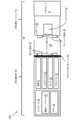
図1Aのブロック図を参照すると、気化器デバイス100は、電源8(例えば充電池であり得るバッテリ)と、アトマイザ26への熱の供給を制御して、気化可能材料を凝集形態(例えば固体、液体、溶液、懸濁液、少なくとも部分的に未処理の植物材料の一部等)から気相へと変換させるコントローラ19(例えば、ロジックを実行可能なプロセッサや回路など)と、を含み得る。コントローラ19は、本対象の特定の実施形態に一致する1つ以上のプリント回路基板(PCB)の一部であってもよい。気化可能材料を気相に変換した後、気化器の種類、気化可能材料の物理的および化学的特性、および/または他の要因に応じて、気相の気化可能材料の少なくとも一部は、ユーザが気化器デバイス100をパフしたり吸ったりする間に濃縮されて、気化器デバイス100によって供給される吸引可能量の一部または全部を形成し得るエアロゾル部分としての気相と少なくとも部分的に局所的平衡状態にある粒子状物質を形成してもよい。気化器デバイス100によって生成されるエアロゾル中の気相と凝集相との間の相互作用は、エアロゾルの1つ以上の物理パラメータに影響を与えることがある要因、例えば、周囲温度、相対湿度、化学的性質、空気流路(気化器デバイス100の内部およびヒトまたは他の動物の気道の内部の両方)における流動条件、および/または気相またはエアロゾル相の気化可能物質と他の空気流との混合などの要因により、複雑かつ動的であり得ることを理解されたい。いくつかの気化器デバイスでは、特に揮発性の気化可能材料の供給のために構成された気化器デバイスでは、吸入可能量は、主に気相で存在し得る(例えば凝縮相粒子の形成は極めて制限される場合がある)。1A, the
本対象の態様は、アトマイザエレメントの使用を含んでいてよく、このアトマイザエレメントは、多孔質である必要はないが、代わりに、液状の気化可能材料が毛管圧によってリザーバから気化のための加熱要素の加熱ゾーンに吸引されるように、構造エレメント間に狭くて濡れ性のあるギャップを含んでもよい構造を有している。このような構造は、制御がより容易な毛管圧や製造の容易性などに関する利点を提供し得る。Aspects of the present subject matter may include the use of atomizer elements that need not be porous, but instead have a structure that may include narrow, wettable gaps between structural elements such that liquid vaporizable material is drawn by capillary pressure from a reservoir to a heating zone of a heating element for vaporization. Such structures may provide advantages such as easier to control capillary pressure and ease of manufacture.
液状の気化可能材料(例えば原液の液体、懸濁液、溶液、混合物等)と共に使用するための気化器デバイス100は、アトマイザ26を含むことができ、このアトマイザ26内では、ウィッキング要素(例えば、毛管圧によって流体運動を生じさせる得る任意の材料を含む得るウィック(図2には図示せず))が、加熱要素(同じく図2には図示せず)を含むアトマイザの部分に液状の気化可能材料の所定量を搬送する。ウィッキング要素は、一般的に、液状の気化可能材料が加熱要素から供給される熱によって気化され得るように、液状の気化可能材料を収容するように構成された(かつ使用時には液状の気化可能材料を含み得る)リザーバから、液状の気化可能材料を引き込むように構成されている。ウィッキング要素は、また、オプションとして、空気がリザーバに入り込み、除去された液体に置き換わること許容してもよい。本対象のいくつかの実施形態では、毛管作用によって液体の気化可能材料が加熱要素によって気化させるためのウィックに引き込まれてもよく、ウィックを介して空気がリザーバ55に戻ってリザーバ内の圧力が少なくとも部分的に均等にされてもよい。A
リザーバ55に戻った空気によって圧力を均等にし得る他の方法も、本対象の範囲内である。例えば、気化器デバイスは、シリカ、綿、またはガラス繊維材料から形成されたウィックを利用している。シリカウィック材料は、例えばシリカガラスの細い連続したフィラメントを最初に糸状に束ねることにより形成されてよく、次いでこれらの糸は、まとめて束ねられて、ウィックとして使用されるコードまたはロープを形成する。このコードは、公称外径、糸の本数、および/または線密度を示す値によって規定されてもよい。Other methods by which pressure may be equalized by air returning to the
本明細書で使用する場合、「ウィック」または「ウィッキング要素」という用語は、毛管圧を介して流体運動を引き起こし得る任意の材料を含む。As used herein, the term "wick" or "wicking element" includes any material that can induce fluid movement via capillary pressure.
加熱要素は、導電性ヒータ、放射ヒータおよび対流性ヒータのうちの1つ以上であってよく、またはこれらのうち1つ以上を含んでいてもよい。加熱要素の1つの形式は、抵抗性加熱要素であり、加熱要素の1つ以上の抵抗セグメントに電流が流されたときに、電力を熱の形で散逸させるように構成された材料(例えば、金属または合金、例えばニッケルクロム合金または非金属抵抗)を含んでもよい。本対象のいくつかの実施形態では、アトマイザは、抵抗コイル、または、ウィッキング要素に巻き付けられるか、ウィッキング要素の中に配置されるか、ウィッキング要素のバルク形状に統合されるか、プレスされてウィッキング要素に熱接触するか、または別の方法でウィッキング要素に熱を運ぶように配置される他の加熱要素を含む得、これにより、ウィッキング要素によってリザーバから引き込まれた液体の気化可能材料は、気相および/または凝縮相(例えば、エアロゾル粒子または液滴)でユーザが続いて吸入することができるように気化される。他のウィッキング要素、加熱要素、および/またはアトマイザアッセンブリ構造も可能である。The heating element may be or may include one or more of a conductive heater, a radiative heater, and a convective heater. One type of heating element is a resistive heating element, which may include a material (e.g., a metal or alloy, such as a nickel-chromium alloy or a non-metallic resistor) configured to dissipate power in the form of heat when an electric current is applied to one or more resistive segments of the heating element. In some embodiments of the present subject matter, the atomizer may include a resistive coil or other heating element wrapped around the wicking element, disposed within the wicking element, integrated into the bulk shape of the wicking element, pressed into thermal contact with the wicking element, or otherwise positioned to transfer heat to the wicking element, such that liquid vaporizable material drawn from the reservoir by the wicking element is vaporized for subsequent inhalation by the user in a gas phase and/or condensed phase (e.g., aerosol particles or droplets). Other wicking element, heating element, and/or atomizer assembly configurations are also possible.
しかしながら、液体がリザーバから繊維状のウィックに引き込まれるアトマイザシステムでは、(例えば、シリカまたは他の繊維状材料の連続フィラメントの端点でウィックとして使用される)リザーバ内の液体と接触するコードの端部位置でまたは端部位置近くで液体が主に引き込まれ、次いで、当該液体が気化が起こるウィック形態の加熱領域へとウィックの主軸に沿って搬送され得る点において限界がある。気化器デバイスの使用中、液体がウィックの加熱された領域から気化されるとき、ユーザが望むほどの速さで加熱された領域に液体が補充されないかもしれず、補充のためにウィックに沿ってより多くの液体が移動する必要がある。そのような設計における液体供給速度の改善が望まれ得る。加えて、ガラス繊維のようなウィック構造に使用される特定の材料は、破壊され易く、ほこりを発生させるおそれがあり、これは望ましくない、かつ/または、有害であり得る。However, atomizer systems in which liquid is drawn from a reservoir into a fibrous wick are limited in that the liquid is drawn primarily at or near the end of the cord (e.g., the end of a continuous filament of silica or other fibrous material used as the wick) that contacts the liquid in the reservoir, and then can be transported along the major axis of the wick to a heated region in the form of a wick where vaporization occurs. During use of the vaporizer device, as liquid is vaporized from the heated region of the wick, the liquid may not replenish the heated region as quickly as the user would like, requiring more liquid to travel along the wick to replenish. Improvements in the liquid delivery rate in such designs may be desirable. Additionally, certain materials used in wick construction, such as fiberglass, can be easily broken down and generate dust, which can be undesirable and/or harmful.
ウィックに基づくアトマイザ設計の一例では、典型的なウィックは、約1.5mmの直径と、長さ1mmあたり約4.7mm2の表面積とを有し得る。加熱されるセクションの長さを増大させることより加熱面積を増やし得るが、気化可能な液体はヒータの中心に到達するためにさらに移動する必要があるだろう。このような構成は、電力密度も増大させずに気化に使用し得る総電力を制限し得る。このことは、電力の増分増加によって気化がより効率的になるというよりはむしろ、液体の損失をもたらすリスクを高め得る。 In one example of a wick-based atomizer design, a typical wick may have a diameter of about 1.5 mm and a surface area of about 4.7mm2 per mm of length. The heated area may be increased by increasing the length of the heated section, but the vaporizable liquid would have to travel further to reach the center of the heater. Such a configuration may limit the total power that can be used for vaporization without also increasing the power density. This may increase the risk that an incremental increase in power will result in loss of liquid, rather than making vaporization more efficient.
液体がリザーバからウィックに引き込まれる従来のアトマイザシステムに関して、さらなる改善が可能であろう。例えば、従来のアトマイザシステムは、多くの構成要素を有していてかなり複雑になり得、ウィックおよびコイルの構成要素の製造や使用に著しい多様性が生じ得る。さらに、上述したように、まず、細い連続したフィラメントを束ねることにより糸状に形成されて、これを束ねてウィックとして使用される紐やロープを形成するウィックは、脆弱であり、その非剛性構造により、精密で慎重な配置が必要となり、製造の複雑さが増している。材料を液体に曝さずに従来のウィックの特定の材料特性(毛管現象など)を正確に測定することは困難である場合がある。所定の材料特性を推定できるかもしれないが、材料の高い圧縮率のために予測は困難である。Further improvements may be possible with respect to conventional atomizer systems in which liquid is drawn from a reservoir into a wick. For example, conventional atomizer systems can be quite complex with many components, resulting in significant variability in the manufacture and use of wick and coil components. Furthermore, as noted above, wicks that are first formed into threads by bundling thin continuous filaments together to form strings or ropes used as wicks are fragile and their non-rigid construction requires precise and careful placement, adding to the complexity of manufacture. It may be difficult to accurately measure certain material properties (such as capillarity) of conventional wicks without exposing the material to liquid. While certain material properties may be estimated, predictions are difficult due to the high compressibility of the material.
他のアトマイザの設計では、従来のウィックおよびコイルの設計が、円筒形のセラミックウィックを組み込むように修正されており、これは、非剛性のウィックを持つという設計上のいくつかの課題と、液体の縦方向の吸引による欠点とに対処している。しかしながらこのような設計は、多数の部品を有する傾向があり、これは複雑な製造にもつながり、他の欠点を有する可能性がある。In other atomizer designs, traditional wick and coil designs have been modified to incorporate cylindrical ceramic wicks, which address some of the design challenges of having a non-rigid wick and the drawbacks of vertical liquid suction. However, such designs tend to have a large number of parts, which can lead to complex manufacturing and can have other drawbacks.
さらに別のアトマイザ設計では、煙突状のコイル設計が実施される。このような設計は、内部に加熱コイルを備える中空管内に形成されたセラミックのウィックを利用する。リザーバからウィックの軸線に沿って液体を引き出すのではなく、液体は煙突状のコイルの周囲を取り囲み、これにより大きなウィッキング面積と短いウィッキング距離がもたらされる。しかし、この設計では部品点数が多くなって、製造が複雑になる傾向がある。Yet another atomizer design implements a chimney coil design. Such a design utilizes a ceramic wick formed within a hollow tube with a heating coil inside. Instead of drawing liquid from a reservoir along the axis of the wick, the liquid wraps around the chimney coil, which results in a large wicking area and short wicking distance. However, this design tends to have a high part count and be complex to manufacture.
上述の各アトマイザは、設計が常に体積的にコンパクトであるとは限らず、これらが組み込まれる気化器デバイスの大部分を占める可能性もあるという付加的な課題を含み得る。アトマイザ体積の低減、ひいては気化可能材料のためにより大きな体積を可能にすることは、気化器設計の主要な目標であり得る。Each of the atomizers mentioned above can include the additional challenge that the designs are not always volumetrically compact and can occupy a large portion of the vaporizer device in which they are incorporated. Reducing atomizer volume, and thus allowing a larger volume for vaporizable material, can be a primary goal of vaporizer design.
特定の気化器デバイスは、付加的にまたは代替的に、例えば固相の気化可能材料(例えばワックス等)または植物材料(例えばタバコの葉および/またはタバコの葉の一部)のように、非液状の気化可能材料の加熱を介して、気相および/またはエアロゾル相の気化可能材料の吸入可能な用量を生成するように構成されてもよい。このような気化器デバイスにおいて、抵抗性加熱要素は、非液体気化可能材料が配置されるオーブンや他の加熱チャンバの壁の一部であるか、またはその壁に組み込まれるか、あるいはそのような壁と熱的に接触されていてよい。代替的に、抵抗性加熱要素は、非液体の気化可能材料を貫流する、またはその周囲を通過する空気を加熱して、非液体の気化可能材料の対流加熱を生じさせるために使用されてもよい。さらに別の例では、抵抗性加熱要素は、(例えば、オーブンの壁から内方への伝導によってのみではなく)植物材料の内部から植物材料の直接伝導加熱が生じるように、植物材料と緊密に接触するように配置されてもよい。Certain vaporizer devices may additionally or alternatively be configured to generate inhalable doses of gas and/or aerosol phase vaporizable material via heating of non-liquid vaporizable material, such as solid phase vaporizable material (e.g., wax, etc.) or plant material (e.g., tobacco leaves and/or portions of tobacco leaves). In such vaporizer devices, the resistive heating element may be part of, incorporated into, or in thermal contact with a wall of an oven or other heating chamber in which the non-liquid vaporizable material is placed. Alternatively, the resistive heating element may be used to heat air passing through or around the non-liquid vaporizable material to cause convective heating of the non-liquid vaporizable material. In yet another example, the resistive heating element may be positioned in intimate contact with the plant material such that direct conductive heating of the plant material occurs from within the plant material (e.g., not only by conduction inwardly from the oven walls).
加熱要素は、ユーザが気化器のマウスピース21をパフ(例えば、吸引、吸入など)することで空気が空気入口からアトマイザ(例えば、ウィッキング要素および加熱要素)を通る空気流路に沿って流通することに伴って作動し得る(例えば、後述するように気化器本体のオプション部分であるコントローラが、電源から電流を後述する気化器カートリッジのオプション部分である抵抗性加熱要素を含む回路を介して流してもよい)。オプションとして、空気は、空気入口から1つ以上の凝縮領域またはチャンバを通って、マウスピースにおける空気出口へと流れてもよい。空気流路に沿って流れる流入空気は、アトマイザを通過する、貫流するなどして、ここで気相の気化可能材料は、空気に混入される。上述したように、混入した気相の気化可能材料は、空気流路の残りを通過するときに凝縮されてよく、これにより、エアロゾル形態の気化可能材料の吸入可能な量が、(例えば、ユーザによる吸入のためのマウスピース21における)空気出口から送出され得る。The heating element may be actuated by a user puffing (e.g., inhaling, sucking, etc.) the
加熱要素の作動は、1つ以上のセンサ29によって生成された1つ以上の信号に基づくパフの自動検出によって行われてもよい。これらのセンサ29は、周囲の圧力に相対的に空気流路に沿った圧力を検出するために(またはオプションとして、絶対圧力における変化を測定するために)配置された1つまたは複数の圧力センサ、気化器デバイス100の1つ以上のモーションセンサ(例えば、加速度計)、気化器デバイス100の1つ以上のフローセンサ、および/または気化器の容量性のリップセンサ、のうちの1つ以上を含んでいてよく、ユーザと1つ以上の入力デバイス41(例えば、気化器デバイス100のボタン、またはその他の触覚制御デバイス)との相互作用の検出、気化器デバイス100と通信するコンピューティングデバイスからの信号の受信に応答して、かつ/またはパフが発生している、または発生しそうであることを決定するためのその他のアプローチを介して行われてもよい。Activation of the heating element may be by automatic detection of a puff based on one or more signals generated by one or more sensors 29. These sensors 29 may include one or more pressure sensors positioned to detect pressure along the airflow path relative to ambient pressure (or optionally to measure changes in absolute pressure), one or more motion sensors (e.g., accelerometers) of the
本明細書で説明するように、本対象の実施形態と一致する気化器デバイス100は、気化器デバイス100と通信する1つのコンピューティングデバイス(またはオプションとして2つ以上のデバイス)に(例えば無線または有線接続を介して)接続するように構成されてもよい。このために、コントローラ19は、通信ハードウェア49を含んでいてよい。コントローラは、メモリ41も含んでもよい。通信ハードウェア49は、ファームウェアを含み得、かつ/または通信のための1つ以上の暗号化プロトコルを実行するためのソフトウェアによって制御され得る。As described herein, a
コンピューティングデバイスは、気化器100も含む気化器システムの構成要素であってよく、気化器デバイス100の通信ハードウェア49と無線通信チャネルを確立し得る通信用の固有のハードウェアを含み得る。例えば、気化器システムの一部として使用されるコンピューティングデバイスは、ソフトウェアを実行してユーザが気化器デバイスとやり取り可能にするためのユーザインタフェースを生成する汎用コンピューティングデバイス(例えば、スマートフォン、タブレット、パーソナルコンピュータ、スマートウォッチのようなその他のポータブルデバイス等)を含むことができる。本対象の他の実施形態では、気化器システムの一部として使用されるそのようなデバイスは、1つ以上の物理的なまたはソフト的なインターフェースコントロール(例えば、画面または他のディスプレイデバイス上で構成可能であり、タッチパネル、またはマウス、ポインタ、トラックボール、カーソルボタンなどの他の入力デバイスとユーザとの間のやり取りを介して選択可能である)を有するリモコンまたはその他の無線もしくは有線デバイスのような、ハードウェアの専用部分であってよい。気化器デバイス100はさらに、ユーザに情報を提供するための1つ以上のアウトプット37またはデバイスを有することができる。例えば、アウトプット37は、気化器デバイス100の状態および/または動作モードに基づいてユーザにフィードバックを提供するように構成された1つ以上の発光ダイオード(LED)を含むことができる。The computing device may be a component of a vaporizer system that also includes the
上記で定義される気化器システムの一部であるコンピューティングデバイスは、以下の1つ以上の機能のうちのいずれかに使用することができる;用量の制御(例えば、用量監視、用量設定、用量制限、ユーザトラッキング等)、セッショニングの制御(例えば、セッションモニタリング、セッション設定、セッション制限、ユーザトラッキング等)、ニコチンの供給の制御(例えば、ニコチンと非ニコチンの気化可能材料との切り替え、供給されるニコチンの量の調整等)、位置情報の取得(例えば、他のユーザの位置、小売店の位置、喫煙所の位置、気化器自体の相対的位置または絶対位置等)、気化器のパーソナライゼーション(例えば、気化器の命名、気化器のロック/パスワード保護、1つ以上のペアレンタルコントロールの調整、気化器のユーザグループへの関連付け、気化器のメーカまたは保証維持組織への登録等)、他のユーザとの社会的活動の従事(例えば、ゲーム、ソーシャルメディア通信、1つ以上のグループとのやり取り等)、またはこれらに類似するもの。「セッショニング」、「セッション」、「気化器セッション」または「蒸気セッション」という用語は、一般に、気化器の使用に費やされる期間を指すために使用される。この期間は、時間、用量の数、気化可能材料の量、および/またはこれらに類するものを含むことができる。A computing device that is part of a vaporizer system as defined above may be used for any of the following functions: controlling dose (e.g., dose monitoring, dose setting, dose limiting, user tracking, etc.), controlling sessioning (e.g., session monitoring, session setting, session limiting, user tracking, etc.), controlling the delivery of nicotine (e.g., switching between nicotine and non-nicotine vaporizable material, adjusting the amount of nicotine delivered, etc.), obtaining location information (e.g., location of other users, location of a retail store, location of a smoking area, relative or absolute location of the vaporizer itself, etc.), personalizing the vaporizer (e.g., naming the vaporizer, locking/password protecting the vaporizer, adjusting one or more parental controls, associating the vaporizer with a user group, registering the vaporizer with a manufacturer or warranty maintenance organization, etc.), engaging in social activities with other users (e.g., gaming, social media communication, interacting with one or more groups, etc.), or the like. The terms "sessioning," "session," "vaporizer session," or "vapor session" are generally used to refer to a period of time spent using a vaporizer. This period can include time, number of doses, amount of vaporizable material, and/or the like.
コンピューティングデバイスが、抵抗性加熱要素の作動に関連する信号を提供する例において、または様々な制御または他の機能の実施のためにコンピューティングデバイスと気化器デバイスとを組み合わせる他の例において、コンピューティングデバイスは、1つまたは複数の一連のコンピュータ指令を実行して、ユーザインタフェースおよび基礎となるデータ処理を提供する。一例では、1つ以上のユーザインタフェース要素とユーザとのやり取りがコンピューティングデバイスによって検出されることにより、コンピューティングデバイスに気化器デバイス100への信号を送らせ、蒸気/エアロゾルの吸入可能な用量を生成するための完全な動作温度まで、または加熱要素の加熱を開始するためのより低い温度まで、加熱要素を作動させ得る。気化器デバイスの他の機能は、気化器デバイスと通信するコンピューティングデバイスにおけるユーザインタフェースとユーザとのやり取りによって制御されてもよい。In examples where a computing device provides signals related to the actuation of a resistive heating element, or in other examples where a computing device and a vaporizer device are combined to perform various control or other functions, the computing device executes one or more sets of computer instructions to provide a user interface and underlying data processing. In one example, user interaction with one or more user interface elements may be detected by the computing device to cause the computing device to send a signal to the
気化器デバイスにおける抵抗性加熱要素の温度は、抵抗性加熱要素に供給される電力量および/または電力が供給されるデューティサイクル、電子気化器デバイスの他の部分および/または環境への伝導性熱伝達、ウィッキング要素および/またはアトマイザ全体からの気化可能材料の気化に起因する潜熱損失、および空気流(例えば、ユーザが気化器デバイスで吸入したときに加熱要素またはアトマイザ全体にわたって移動する空気)に起因する対流熱損失、を含む複数の要因に依存し得る。本明細書で述べた通り、加熱要素を確実に活性化するために、または加熱要素を所望の温度まで加熱するために、本対象のいくつかの実施形態では、気化器デバイスがセンサ(例えば圧力センサ)からの信号を使用してユーザが吸入しているタイミングを決定してもよい。センサは、空気流路に配置することができ、かつ/または(例えば通路または他の通路によって)空気がデバイスに入るための入口と、生じた蒸気および/またはエアロゾルをユーザが吸入するための吹出口とを含む空気流路に接続することができる。その結果、センサは、気化器デバイスを介して空気入口から空気出口へと通過する空気による同時的な変化(例えば圧力変化)を検知する。本対象のいくつかの実施形態では、加熱要素は、ユーザのパフに伴って、例えば空気流路における変化(例えば圧力変化)を検出する圧力センサによるパフの自動検出によって、作動してもよい。The temperature of a resistive heating element in a vaporizer device may depend on several factors, including the amount of power provided to the resistive heating element and/or the duty cycle at which power is provided, conductive heat transfer to other parts of the electronic vaporizer device and/or the environment, latent heat loss due to vaporization of the vaporizable material from the wicking element and/or across the atomizer, and convective heat loss due to airflow (e.g., air moving across the heating element or atomizer when a user inhales on the vaporizer device). As discussed herein, to ensure activation of the heating element or to heat the heating element to a desired temperature, in some embodiments of the present subject matter, the vaporizer device may use a signal from a sensor (e.g., a pressure sensor) to determine when a user is inhaling. The sensor may be located in the air flow path and/or connected (e.g., by a passageway or other passageway) to an air flow path that includes an inlet for air to enter the device and an outlet for the user to inhale the resulting vapor and/or aerosol. As a result, the sensor detects a simultaneous change (e.g., pressure change) due to air passing from the air inlet to the air outlet through the vaporizer device. In some embodiments of the present subject matter, the heating element may be activated in conjunction with a user's puff, for example by automatic detection of the puff by a pressure sensor that detects a change (e.g., a pressure change) in the airflow path.
センサ29は、コントローラ19(例えばプリント回路基板アセンブリまたは他の形式の回路基板)上に配置することができ、またはコントローラ19に連結(例えば物理的接続または無線接続を介して電気的または電子的に接続)することができる。測定を正確に行ったり、気化器デバイス100の耐久性を維持したりするために、空気流路を気化器デバイス100の他の部分から分離するための弾性シール60を設けることが有益であり得る。ガスケットであり得るシール60は、センサ29を少なくとも部分的に取り囲むように構成されてもよく、これにより気化器デバイス100の内部回路へのセンサ29の接続部は、センサ29のうちの空気流路に曝される部分から分離される。カートリッジ形式の気化器の例では、シール60が気化器本体50と気化器カートリッジ52との間の1つ以上の電気接続部の一部をさらに分離してもよい。気化器デバイス100内のシール60のこのような配置は、蒸気相または液相の水、気化可能材料等の他の流体のような環境要因との相互作用によって生じる気化器構成要素に対する潜在的で破壊的な影響を緩和するのに役立ち得、かつ/または、気化器デバイス100内の指定された空気流路からの空気の漏れを低減するのに役立ち得る。気化器デバイス100の回路を通過する、および/または、当該回路に接触する望ましくない空気、液体、またはその他の流体は、圧力読取り値が変化する等の様々な望ましくない影響を引き起こし得、かつ/または、圧力信号の不良、センサまたは他の構成要素の劣化、および/または気化器デバイス100の寿命短縮を引き起こすであろう気化器の一部における湿気や気化可能材料の過剰等の望ましくない材料の堆積を引き起こし得る。また、シール60での漏れは、吸引すると望ましくないであろう材料を含んだり、あるいはこのような材料から成る気化器デバイス100の部分を通過した空気をユーザが吸引したりする結果をもたらし得る。The sensor 29 may be located on the controller 19 (e.g., a printed circuit board assembly or other type of circuit board) or may be coupled to the controller 19 (e.g., electrically or electronically connected via a physical or wireless connection). To ensure accurate measurements and to maintain the durability of the
いくつかの実施形態では、気化器本体50は、コントローラ19、電源8(例えばバッテリ)、1つ以上のセンサ、(例えば電源8を充電するための)充電接点、ガスケットまたはシール機構(またはシール)60、および1つ以上の様々なアタッチメント構造を介して気化器本体50と連結するための気化器カートリッジ52を受け入れるように構成されたカートリッジレセプタクル69を含む。いくつかの例において、気化器カートリッジ52は、液状の気化可能材料を収容するためのリザーバ55と、ユーザに吸入可能な一服を供給するためのエアロゾル出口を有するマウスピース21とを含む。気化器カートリッジは、ウィッキング要素および加熱要素を有するアトマイザ26を含むことができ、あるいは代替的に、ウィッキング要素および加熱要素のうちの一方または両方を気化器本体50の一部とすることができる。アトマイザ26の任意の部分(例えば加熱要素および/またはウィッキング要素)が気化器本体50の一部である実施形態では、気化器デバイスは、気化器カートリッジ内のリザーバから液状の気化可能材料を気化器本体に含まれるアトマイザ部分に供給するように構成され得る。In some embodiments, the
非液体気化可能材料の加熱によって吸入可能量の非液体気化可能材料を生成する気化器用のカートリッジ形式の構成も、本対象の範囲内である。例えば、気化器カートリッジは、1つ以上の抵抗性加熱要素の一部と直接接触するように加工・形成された植物材料の集合体を含んでもよく、そのような気化器カートリッジは、コントローラと、電源と、対応するカートリッジ接点に接続して1つ以上の抵抗性加熱要素とともに回路を完成させる受け口接点と、を含む気化器本体に、機械的および電気的に接続するように構成されてもよい。Also within the scope of the present subject matter are cartridge-type configurations for vaporizers that generate inhalable quantities of non-liquid vaporizable material by heating the non-liquid vaporizable material. For example, a vaporizer cartridge may include a mass of plant material that is processed and formed to directly contact a portion of one or more resistive heating elements, and such a vaporizer cartridge may be configured to mechanically and electrically connect to a vaporizer body that includes a controller, a power source, and receptacle contacts that connect to corresponding cartridge contacts to complete a circuit with the one or more resistive heating elements.
電源8が気化器本体50の一部であり、気化器本体50に連結されるように構成された気化器カートリッジ52内に加熱要素が配置された気化器デバイスでは、気化器100は、コントローラ(例えば、プリント回路基板、マイクロコントローラなど)と、電源と、加熱要素とを含む回路を完成させるための電気接続機能(例えば、回路を完成させるための手段)を含んでもよい。これらの電気接続機能は、気化器カートリッジ52の下面における少なくとも2つの接点(本明細書ではカートリッジ接点65と称される)と、気化器デバイス100のカートリッジレセプタクルの基部付近に配置された少なくとも2つの接点(本明細書では受け口接点62と称される)とを含むことができ、カートリッジ接点65と受け口接点62とは、気化器カートリッジ52がカートリッジレセプタクル69に挿入されて連結されたときに電気的に接続する。これらの電気的な接続によって完成された回路は、電流が加熱要素に流れることを許容し得、さらに、例えば、抵抗性加熱要素または気化器カートリッジの他の回路の1つ以上の電気的特性に基づいてカートリッジを識別する等の目的で、加熱要素の抵抗率の熱係数に基づく加熱要素の温度の決定および/または制御に使用するための加熱要素における抵抗測定のような付加的な機能のために使用されてもよい。In a vaporizer device in which the power source 8 is part of the
本対象のいくつかの実施形態では、少なくとも2つのカートリッジ接点および少なくとも2つの受け口接点は、少なくとも2つの向きのいずれかで電気的に接続するように構成され得る。換言すれば、気化器の動作に必要な1つ以上の回路は、気化器カートリッジ52がカートリッジレセプタクル69に第1の回転方向で(気化器本体50のカートリッジレセプタクル69内に気化器カートリッジ52が挿入される軸線を中心として)挿入されることにより完成され得、これにより、少なくとも2つのカートリッジ接点65のうち第1のカートリッジ接点が少なくとも2つの受け口接点62のうち第1の受け口接点に電気的に接続されるとともに、少なくとも2つのカートリッジ接点65のうち第2のカートリッジ接点が少なくとも2つの受け口接点62のうち第2の受け口接点に電気的に接続される。さらに、気化器の動作に必要な1つ以上の回路は、気化器カートリッジ52がカートリッジレセプタクル69に第2の回転方向で挿入されることにより完成され得、これにより、少なくとも2つのカートリッジ接点65のうち第1のカートリッジ接点が少なくとも2つの受け口接点62のうち第2の受け口接点に電気的に接続されるとともに、少なくとも2つのカートリッジ接点65のうち第2のカートリッジ接点が少なくとも2つの受け口接点62のうち第1の受け口接点に電気的に接続される。In some embodiments of the present subject matter, the at least two cartridge contacts and the at least two receptacle contacts may be configured to be electrically connected in either of at least two orientations. In other words, one or more circuits required for the operation of the vaporizer may be completed by inserting the
気化器カートリッジ52を気化器本体に連結するための取り付け構造の一例では、気化器本体50は、カートリッジレセプタクル69の内面から内方に突出した1つ以上のディテント(例えば、くぼみ、突出部など)、カートリッジレセプタクル69内に突出する部分を含むように形成された追加材料(例えば、金属、プラスチックなど)、および/またはこれらに類するものを含む。気化器カートリッジ52の1つ以上の外面は、気化器本体50におけるカートリッジレセプタクル69に気化器カートリッジ52が挿入されたときに、そのようなディテントまたは突出部に嵌合および/またはその他の形式で咬合し得る対応凹部(図1Aには示されていない)を含み得る。気化器カートリッジ52と気化器本体50とが(例えば、気化器カートリッジ52の端部が気化器本体50のカートリッジレセプタクル69に挿入されることにより)連結されるとき、気化器本体50のディテントまたは突出部が気化器カートリッジ52の凹部内に嵌合かつ/またはその他の形式で保持されて、組み立てられた気化器カートリッジ52をその位置に保持してもよい。このようなアッセンブリは、少なくとも2つのカートリッジ接点65と少なくとも2つの受け口接点62との間の良好な接触を保証するために気化器カートリッジ52を所定の位置に保持するのに十分な支持を提供することができ、一方で、ユーザが気化器カートリッジ52をカートリッジレセプタクル69から離脱させるために気化器カートリッジ52に適度な力を加えて引っ張った際に、気化器カートリッジ52が気化器本体50から離脱することを許容する。In one example of an attachment structure for coupling the
いくつかの実施形態では、カートリッジレセプタクル69は、気化器カートリッジ52がカートリッジレセプタクル69に挿入される方向の軸線に対して横断する非円形の断面を有してもよい。例えば、非円形断面は、ほぼ長方形、ほぼ楕円形(例えば、ほぼ長円形)、2組の平行なまたはほぼ平行な対向する辺を有しているが長方形ではない(例えば、平行四辺形のような形状を有する)非長方形、または少なくとも2回対称の他の形状であってよい。この文脈では、近似形状とは、記述された形状に対する基本的な類似性は明らかであるが、問題となっている形状における縁が完全に直線状である必要はなく、また、頂点が完全に鋭角である必要がないことを意味する。断面形状の縁部もしくは頂点の双方もしくは一方の丸みは、本明細書において言及されるあらゆる非円形の断面についての記載において考慮される。In some embodiments, the
少なくとも2つのカートリッジ接点65および少なくとも2つの受け口接点62は、様々な形態を取ることができる。例えば、接点の一方または両方の組は、導電性のピン、タブ、端子、ピンまたは端子を受け入れる穴、またはこれらに類するものを含んでもよい。いくつかのタイプの接点は、気化器カートリッジの接点と気化器本体の接点との間のより良好な物理的および電気的な接続を容易にするためのばね又は他の特徴を含んでもよい。電気接点は、オプションとして金メッキされていてよく、かつ/または他の材料を含んでいてよい。The at least two
本対象の1つ以上の実施形態の特徴に一致する気化器デバイス用のアトマイザコンポーネントは、本明細書に記載するような付加的な利益も取り込みながら、現在の気化器の構成、製造方法などに関する利点および改善も提供することができる。Atomizer components for vaporizer devices conforming to features of one or more embodiments of the present subject matter can provide advantages and improvements over current vaporizer configurations, manufacturing methods, and the like, while also incorporating additional benefits as described herein.
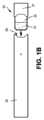
図1Bは、気化器カートリッジ52を取外し可能に挿入し得るカートリッジレセプタクル69を有する気化器本体50の実施例を示している。図1Bは、気化器本体50内へ挿入するために配置された気化器カートリッジ52が表された気化器デバイス100の平面図を示す。ユーザが気化器デバイス100でパフすると、空気が気化器カートリッジ52の外面と気化器本体50におけるカートリッジレセプタクル69の内面との間を通過し得る。そして、空気は、カートリッジ52の挿入可能な端部内に引き込まれて、加熱要素とウィックとを有する又は収容する気化チャンバを通って、吸引可能なエアロゾルをユーザに届けるためにマウスピース21の出口から排出される。気化器カートリッジ52のリザーバ55は、気化器カートリッジ52の内部の気化可能材料の充填レベルが視認できるように、全体または一部が半透明の材料から形成されてもよい。マウスピース21は、気化器カートリッジ52の分離可能な構成要素であり得、あるいは、気化器カートリッジ52の他の構成要素と一体形成されてもよい(例えば、リザーバ55および/またはこれに類するものとの一体構造として形成される)。FIG. 1B shows an example of a
カートリッジレセプタクル69における気化器カートリッジ52の少なくとも2つの回転方向が可能であるように可逆的である気化器カートリッジ52と気化器本体50との間の電気接続に関する上記の説明に加えてさらに、いくつかの気化器デバイスでは、気化器カートリッジ52の形状、またはカートリッジレセプタクル69内に挿入されるように構成された気化器カートリッジ52の少なくとも端部の形状は、少なくとも2回対称を有していてよい。換言すれば、気化器カートリッジ52または気化器カートリッジ52の少なくとも挿入可能な端部は、気化器カートリッジ52がカートリッジレセプタクル69に挿入される方向の軸線を中心として180°回転されるとき対称であってよい。このような構成では、気化器デバイス100の回路機構は、気化器カートリッジ52のどちらの対称的な向きが生じるかに関わらず、同じ動作をサポートすることができる。In addition to the above description of the electrical connection between the
図1C~図1Dは、本対象の実施形態に一致する気化器デバイスに含まれてよい例示的な特徴を示す。図1Cおよび図1Dは、気化器カートリッジ52を気化器本体50に接続される前(図1C)および接続された後(図1D)における例示的な気化器デバイス100の平面図を示す。1C-1D show exemplary features that may be included in a vaporizer device consistent with embodiments of the present subject matter. FIGS. 1C and 1D show plan views of an
図1Eは、液状の気化可能材料51を保持する気化器カートリッジ52の1つのバリエーションの斜視図を示している。ニコチンまたは他の有機材料の溶液を含む任意の適切な気化可能材料51は、気化器カートリッジ52の内部(例えば、リザーバ55の内部)に収容されてよい。FIG. 1E shows a perspective view of one variation of a
図1Fは、分離可能な気化器カートリッジ52に連結された気化器本体50を含む気化器デバイス100の別の例の斜視図を示す。図示したように、気化器デバイス100は、気化器デバイス100の状態、動作モードおよび/またはこれに類するものに基づいてユーザに情報を提供するように構成された1つ以上のアウトプット37(例えば、LED)を含み得る。いくつかの態様では、1つ以上のアウトプット37が、複数のLED(例えば2つ、3つ、4つ、5つ、または6つのLED)を含み得る。1つ以上のアウトプット37(例えば、個々のLEDのそれぞれ)は、1つ以上の色(例えば白、赤、青、緑、黄など)の光を表示するように構成され得る。1つ以上のアウトプット37は、(例えば、特定のLEDを照明する、時間の経過に伴って1つ以上のLEDの光強度を変化させる、1つ以上のLEDを異なる色で照明する、などして)様々な光パターンを表示して、気化器デバイス100の異なる状態、動作モード、および/またはこれらに類するものを示すように構成され得る。いくつかの実施形態では、1つ以上のアウトプット37は、気化器デバイス100の底端部領域43の近位に位置し得、かつ/または、少なくとも部分的に底端部領域43内に配置され得る。気化器デバイス100は、付加的にまたは代替的に、外部からアクセス可能な充電接点47を含んでもよい。充電接点47は、気化器デバイス100の底端部領域の近位に位置し得、かつ/または、少なくとも部分的に底端部領域内に配置され得る。FIG. 1F illustrates a perspective view of another example of a
図2Aは、本対象の実施形態に一致する加熱要素120およびリザーバ55の概略図を示す。加熱要素120は、1つ以上の毛管ギャップおよび通路等の毛管構造を画定、かつ/または、包含してもよい。FIG. 2A shows a schematic diagram of a
加熱要素120は、毛管構造を画定するために分離された1つ以上(例えば2つ以上)の剛体部分を含んでもよい。例えば、1つ以上の剛体部分は、スパン128(例えば、毛管ギャップ、通路など)によって分離された第1のプレート部分124と第2のプレート部分126とを含んでもよい。スパン128は、第1および第2のプレート部分124,126を隔てる間隙を含む。換言すれば、スパン128のサイズは、第1のプレート部分124と第2のプレート部分126との間の距離である。スパン128は、気化可能材料のような流体を、様々な向きで剛体部分の間に保持すること、かつ/または、様々な向きで剛体部分の間のスペースに引き込むこと、を可能にし得る。例えば、剛体部分(例えば、第1のプレート部分124および第2のプレート部分126)は、好ましくは、スパン128によって隔てられて、流体(例えば気化可能材料)が気化器カートリッジ52のリザーバ55から、例えば毛管作用を介して、加熱要素120の気化部122(例えば気化部122A,122B)(気化部で流体は加熱されて、かつ/または気化されてエアロゾルが生成される)へ搬送される、かつ/または引き出されることを許容する。The
スパン128は、剛体部分の間で流体を吸引しかつ/または別の形式で保持するために、強くかつ/または十分な毛管力を維持するように狭くされることが望ましい場合がある。例えば、スパン128のサイズによって、流体がスパン128内に補充される速度を制御してもよい。いくつかの実施形態において、望ましくは、スパン128は、気化可能材料が過度に迅速にスパン128に出入りすることを制限または防止するように、かつ/または、スパン128内の気化可能材料を保持するように、選択かつ/またはサイズ調整され得る。いくつかの実施形態では、スパン128のサイズが選択かつ/またはサイズ調整されて、スパン128がパフ中に補充される必要がないように、かつ/または、パフ中および/またはパフ後に容易に補充され得るように、スパン128が気化可能材料の十分な量を保持することを可能にすることが好ましい場合がある。It may be desirable for the
いくつかの実施形態において、スパン128のサイズ(例えば、第1のプレート部分124と第2のプレート部分126との間の距離)は、約0.1mm~0.2mm、0.1mm~0.5mm、0.1mm~1mm、0.2mm~0.5mm、0.3mm~0.5mm、0.5mm~0.7mm、0.7mm~0.9mm、1.0mm~1.5mm、1.5mm~2.0mm、2.0mm~2.5mm、2.5mm~3.0mm、および/またはこれらの間の他の範囲にある。いくつかの実施形態では、スパン128のサイズは、第1および第2のプレート部分124,126のそれぞれの厚さにほぼ等しい。いくつかの実施形態では、スパン128のサイズは、気化部122における加熱要素120の厚さにほぼ等しい。いくつかの実施形態では、スパン128のサイズは、第1および第2のプレート部分124,126の厚さよりも大きい。別の実施形態では、スパン128のサイズは、第1および第2のプレート部分124,126の厚さよりも小さい。いくつかの実施形態では、スパン128の第1の長さに沿ったスパン128のサイズは、第1および第2のプレート部分124,126の厚さよりも大きく、スパン128の第2の長さに沿ったスパン128のサイズは、第1および第2のプレート部分124,126の厚さよりも小さい。In some embodiments, the size of the span 128 (e.g., the distance between the
いくつかの実施形態では、スパンの長さは、第1および第2のプレート部分124,126の長さにほぼ等しい。いくつかの実施形態では、スパンの長さは、加熱要素120の気化部122の長さにほぼ等しい。いくつかの実施形態では、スパン128の長さは、スパン128のサイズよりも大きい。In some embodiments, the length of the span is approximately equal to the length of the first and
いくつかの実施形態では、加熱要素120の剛体部分(例えば、第1および第2のプレート部分124,126)の寸法は、剛体部分(例えば、第1のプレート部分124および/または第2のプレート部分126)にわたる最大の流体静力学的電位を最小限に抑えるために選択することができる。また、所定の量の気化可能材料を選択的に引き出すために(かつ/またはリザーバに戻すために、かつ/またはリザーバ内の気化可能材料を交換するために、背圧を均等化するために)、かつ/または所定の量の空気が加熱要素120を通過する、加熱要素120のそばを通る、加熱要素120を超える、かつ/または加熱要素120の周囲を通ることを許容するために、リザーバ55内に位置する加熱要素120の部分のような加熱要素120の1つ以上の部分において、スパン128のサイズが変更され得る。いくつかの実施形態では、ヒータ内に気化可能材料の流れを受け入れるための加熱要素120の部分におけるスパン128のサイズは、リザーバ55へのかつ/またはリザーバ55からの空気流(例えば戻り)を許容するための加熱要素120の部分におけるスパン128のサイズと同じであってよく、かつ/または異なっていてよい。In some embodiments, the dimensions of the rigid portions of the heating element 120 (e.g., the first and
したがって、本対象の実施形態に一致する加熱要素120は、気化器デバイス100によって加熱および気化される気化可能材料の量を効率的に制御することができる。加熱要素120は、付加的かつ/または代替的に、繊維状のウィッキング要素などのウィッキング要素を使用せずとも気化器デバイス100が気化可能材料を加熱および気化してエアロゾルを生成することを可能にするだろう。Thus, a
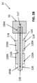
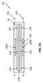
図2A~図2Dを参照すると、加熱要素120(例えば、毛管構造)は、第1のプレート部分124および第2のプレート部分126を含む。上述のように、第1のプレート部分124および第2のプレート部分126は、1つ以上の剛体部分を画定する。第1および第2のプレート部分124,126の各々は、近位端部193Aから遠位端部193Bまで延びている。近位端部193Aはリザーバ55内に配置されてもよく、遠位端部193Bはリザーバ55の外に、かつ/または、リザーバ55から離れて配置されてもよい。例えば、図2Bは、例示的な空気通路118および流体通路117と共に加熱要素120およびリザーバ55の概略的な側面図を示しており、図2Cは、例示的な空気通路118と共に、加熱要素120およびリザーバ55の概略的な底面図を示している。2A-2D, the heating element 120 (e.g., a capillary structure) includes a
図2Dは、展開された構成の加熱要素120の例を示している。例えば、第1のプレート部分124および第2のプレート部分126は、中央横方向軸線に沿って折り曲げられた単一の構造体として一体形成することができる。いくつかの例示的な製造方法では、加熱要素120は、スタンピング、パンチング加工、レーザ切断、ブランク加工、ダイカスト、延伸成形、および/または他の製造プロセスによって単一のプレートとして形成され得る。FIG. 2D illustrates an example of the
加熱要素120は、例えば、非多孔質駆動の毛管現象を通じて気化可能材料をリザーバ55から引き出すために加熱され得る抵抗加熱構造を形成し得る。例えば、加熱要素120は、導電性材料から形成され得る。いくつかの実施形態では、加熱要素120の少なくとも一部は、上述の、およびその他の製造プロセスのいずれかによって加熱要素120が形成される前または後に、導電性材料によってめっきされ得る。加熱要素120が形成されると、加熱要素120は第1のプレート部分124と第2のプレート部分126との間で中心横方向軸線に沿って折り畳まれ得、その結果、第1および第2のプレート部分124,126のうち少なくとも気化部122A,122Bがほぼ平行となり、スパン128(例えば、毛管ギャップ)を形成し、かつ/または、毛管作用を誘発する。いくつかの実施形態では、第1および第2のプレート部分124,126は、互いに対して傾斜している。いくつかの実施形態では、また、加熱要素120は、より詳細に後述するように、セパレートヒータ120Aまたはヒータ回路トレース120Aを含んで加熱要素120を加熱してもよい。The
図2Cに示したように、第1および第2のプレート部分124,126は、気化可能材料が毛管ギャップから空気通路118に排出されることを可能にするための1つ以上のギャップを有するように形成され得る。ギャップは第1および第2のプレート部分124,126の隣接する区分の縁部によって取り囲まれ得、これにより、気化可能材料が毛管ギャップから空気通路118に排出されることが許容される。As shown in FIG. 2C, the first and
一般に、ユーザが気化器カートリッジ52のマウスピース21でパフする際、空気は、気化器カートリッジ52内に流通して空気通路118に沿って流通する。ユーザのパフに伴って、加熱要素120は以下に説明するように作動されてもよい。加熱要素120が作動されると、加熱要素120に流れる電流により温度が上昇して発熱する。熱は、伝導性熱伝達、対流性熱伝達、および/または放射性熱伝達を介して気化可能材料の所定量まで伝達されて、気化可能材料の少なくとも一部が気化する。この熱伝達は、リザーバ内の気化可能材料および/または毛管ギャップ内に配置された気化可能材料に起こり得る。図2Cに示したように、気化器カートリッジ52内を通過する空気は、空気通路118に沿って流れ、気化された気化可能材料を加熱要素120から離れさせる。このような実施形態では、熱が気化器カートリッジ52のリザーバ55および/または他の部分内へ自由に伝導されないだろうから、廃熱は制限されるだろう。Generally, when a user puffs on the
図3A~図9は、加熱要素120を組み込み得る本対象のいくつかの実施形態に一致する気化器カートリッジ52(またはその一部)の例を示す。気化器カートリッジ52は、バッテリおよび制御回路を有する気化器本体50(図示せず)と共に使用されてもよく、かつ/または、気化器本体50に連結されてもよく、さらに、気化可能材料を気化し得る加熱要素120に気化可能材料が入る前かつ/または入る際に気化可能材料を加熱して吸入可能な蒸気を生成するように構成されてよい。3A-9 show examples of a vaporizer cartridge 52 (or a portion thereof) consistent with some embodiments of the present subject matter that may incorporate a
気化器カートリッジ52は、気化可能材料(オイル、溶液、またはその他何らかの流体または液体等)を保持するためのリザーバ(またはタンク)55、マウスピース21、空気入口106、およびリザーバ55内に収容された流体の内部にまたは当該流体に接触して配置されるアトマイザチャンバ110を含み得る。図3Bに示すように、アトマイザチャンバ110は、加熱要素ハウジング112、カートリッジ接点65(レセプタクル、端子等)、アトマイザチャンバ空気入口116、および加熱要素120を含み得る。アトマイザチャンバ110は、少なくとも部分的に加熱要素120を取り囲み、かつ/または、支持し得る。いくつかの態様によれば、アトマイザチャンバ110は、例えば、超音波溶接、高周波(RF)溶接、スナップ嵌め接続、またはその他任意の安全な接続方法によって気化器カートリッジ52内に固定され得る。いくつかの実施形態において、アトマイザチャンバ110は、気化器カートリッジ52から取外し可能である。The
図3Aに示したように、カートリッジ52は、少なくとも2つのカートリッジ接点65を含んでもよい。カートリッジ接点65は、電気コネクタおよび/または電源8を受け入れ、かつ/または、これらに接触する任意の形状および/または構造を含み得る。いくつかの実施形態では、カートリッジ接点65は、さらに温度、電気抵抗、および/またはセンサの読取りまたは測定のために、少なくとも4つのカートリッジ接点65を含む。As shown in FIG. 3A, the
カートリッジ接点65は、カートリッジ52が気化器本体50に組み付けられたときに気化器本体50の対応する受け口接点62を受け入れるように、またはこれに接触するように構成され得る。カートリッジ接点65は、アトマイザチャンバ110の底面からアトマイザチャンバ110の内部容積に向かって内側へ延在し得る。いくつかの実施形態では、カートリッジ接点65の上端部は、接点領域109(図6参照)で、接点部130のような加熱要素120の少なくとも一部に接触かつ/または他の形式で連結し得る。いくつかの実施例では、カートリッジ接点65は、例えば、スポット溶接、超音波溶接、高周波(RF)溶接、スナップ嵌め接続、またはその他任意の他の安全な接続方法によって、接点部130に固定されている。いくつかの実施形態では、接点領域109は、ヒータ領域108の少なくとも一部と重なり得る。いくつかの実施形態では、カートリッジ接点65は、ヒータ領域108内に延在して、加熱要素120の一部に接触し得る。The
カートリッジ接点65は、例えば気化器本体50の受け口接点62を介して、バッテリのような電源8と加熱要素120における接点部130との間の電気的接続を提供し得る。電源8と加熱要素120における接点部130との間の電気的接続は、本明細書により詳細に記載されているように、少なくとも気化部122を加熱することを可能にし得る。The
図5Aは、加熱要素120の斜視図を示している。いくつかの実施形態によれば、加熱要素120は、接続されて対向する一対のプレートまたは剛体部分として形成され得る。加熱要素120は、第1のプレート部分124および第2のプレート部分126を含む。第1のプレート部分124および/または第2のプレート部分126は、(例えば、カートリッジ接点65の各々に電気的に接続可能なまたは他の方式で接続可能な)それぞれの接点部130と、対向するタイン123A,123B(例えば金属タイン)から成る気化部122と、上部コネクタ132と、上部加熱要素支持部134と、下部加熱要素支持部136とを含み得る。5A shows a perspective view of the
第1のプレート部分124および/または第2のプレート部分126は、気化部122を含み得る。気化部122は、ほぼ正弦波形状(または断面形状)を有し得る。いくつかの実施形態では、気化部122は、ほぼ長方形、楕円形、または他の形状(または断面形状)であり得る。気化部122は、気化可能材料が毛管ギャップから空気通路118に排出されることを可能にするための1つ以上のギャップを気化部内に有するように形作られ得る。例えば、ギャップは気化部122の隣接する区分の縁部によって取り囲まれて、気化可能材料が毛管ギャップから空気通路118に排出されることを可能にし得る。The
加熱要素120の第1のプレート部分124および第2のプレート部分126は、一体に形成され得る。例えば、第1のプレート部分124および第2のプレート部分126は、プレートの中央横方向軸線に沿って折り曲げられる単一のプレートによって形成され得る。図5Bは、強調して示した第1のプレート部分124の例と共に、アトマイザコンポーネント120の斜視図を示している。他の実施形態では、第1のプレート部分124および第2のプレート部分126は、別個に形成されてコネクタ132に連結され得る。さらに他の実施例では、第1のプレート部分124および第2のプレート部分126は、形成後に分離されたままであるが、別の方法で電気的に接続され得る。The
図5Cは、特定の実施形態に一致する加熱要素120の上断面図を示している。図5Cに示したように、第1のプレート部分124は上部気化部122Aを有し得、第2のプレート部分126は下部気化部122Bを有し得る。上部気化部122Aと下部気化部122Bとの間の距離は、第1のプレート部分124と第2のプレート部分126との間のスパン128内に、気化可能材料を引き込むかつ/または保持するための所望の毛管力に応じて調整され得る。いくつかの実施形態において、スパン128(例えば毛管ギャップ)のサイズは、流体領域107(図6に示されている)からヒータ領域108(図6に示されている)全体にわたって一定であり得る。付加的にかつ/または代替的に、スパン128のサイズは、流体通路117に沿って変化し得る。例えば、スパン128のサイズは、流体が近位の流体領域107から遠位のヒータ領域108へと引き込まれるにつれて狭くなり得、これにより、流体通路117に沿ってより大きな毛管圧力差が生じる。5C illustrates a top cross-sectional view of the
図5Cを参照すると、上部気化部122Aは、上部気化部122Aの隣接するヒータタイン123Aの間に形成されたギャップ152Aを有し得る。下部気化部122Bは、下部気化部122Bの隣接するヒータタイン123Bの間に形成されたギャップ152Bを有し得る。上部気化部122Aと下部気化部122Bとは、上下のヒータタイン123A,123Bが少なくとも部分的に互いに上下方向で重なるように寸法調整およびオフセットされ得る。この構成において、上部ギャップ152Aは、それぞれの下部ヒータタイン123Bにほぼ対向してもよい。下部ギャップ152Bは、それぞれの上部ヒータタイン123Aに例えば横方向に沿ってほぼ対向してもよい。このような実施形態は、好ましくは、気化可能材料1が、加熱要素120の少なくとも全長(例えば、実質的な部分)にわたって、例えば第1および第2のプレート部分124,126の間の加熱要素120の断面全体にわたって、スパン128内に保持されることを許容する。図5Cの例示的な加熱要素120に示されるように、対向してオフセットされたこれらヒータタイン123A,123Bの間の毛管ギャップ内に保持された気化可能材料の断面は、タインからタインへ流通する流体の表面張力に少なくとも部分的に起因して、ほぼ正弦波状の形状を有し得る。毛管作用を受ける気化可能材料のこの断面形状は、毛管ギャップ内に配置されるエアギャップを制限し、かつ/または毛管ギャップ内に保持され得る気化可能材料の量を最大化するため、望ましい場合がある。オフセットされたギャップ152Aおよび152Bは、各ギャップ152Aの下方(例えば、第1のプレート部分124と第2のプレート部分126との間で)で加熱されて、それぞれのギャップ152Aの側面へ向かう気化可能材料が効率的に気化されて空気通路118内に混入することを可能にする。5C, the
図6は、本対象の実施形態に一致する加熱要素120が組み込まれている気化器カートリッジ52の断面図を示している。図6に示されるように、気化器カートリッジ52は、流体領域107と、ヒータ領域108と、接点領域109とを含む。流体領域107は、気化可能材料と接触する気化器カートリッジ52の少なくとも一部を表している。いくつかの実施形態において、加熱要素120の少なくとも一部は、気化器カートリッジ52の少なくとも1つの領域において気化可能材料と流体連通している。Figure 6 illustrates a cross-sectional view of a
図7Aおよび図7Bは、気化器カートリッジ52の一実施例の側断面図を示している。図7Aは、流体領域107を強調表示している。流体領域107は、リザーバ55と、加熱要素120の少なくとも近位の部分123(特に、1つの実施例では、加熱要素120の第1のプレート部分124と第2のプレート部分126との間の露出した領域)とを含み得る。これにより、流体の気化可能材料は、第1のプレート部分124と第2のプレート部分126との間のギャップに入り込んで、第1のプレート部分124と第2のプレート部分126との間で、毛管作用によってヒータ領域108に向かって、ウィックを介して或いは他の形式で運ばれ得る。7A and 7B show side cross-sectional views of one embodiment of
図7Bは、例示的な気化器カートリッジ52の同じ側断面図を示しており、ヒータ領域108が強調表示されている。ここでは、ヒータ領域108は、加熱要素120の少なくとも遠位の部分193B(特に、1つの実施例では、加熱要素120の気化部122における第1のプレート部分124と第2のプレート部分126との間の露出した領域)を含んでいる。これにより、流体の気化可能材料は第1のプレート部分124と第2のプレート部分126との間のギャップから気化し得る。気化部122は、少なくとも部分的に空気によって囲まれ得(例えば、図2B、図2C、図5C参照)、これにより、ウィックを介してかつ/または他の形式で流体領域107からヒータ領域108へと運ばれた気化可能材料の気化が容易になり得る。ヒータ領域108中の少なくとも空気で満たされた部分の例が、図7Bに強調表示されている。7B shows the same cross-sectional side view of the
図2B、図2C、図5Cおよび図6には空気通路118が示されている。空気は、例えば空気入口106を介して、気化器カートリッジ52の少なくとも一方の側から引き込まれてもよい。空気入口106は、アトマイザチャンバ入口116と整列され得る(図3A参照)。入口106,116が整列することにより、気化器本体50の周囲または部分からアトマイザチャンバ110内に空気を直接引き込むことが可能になり得る。代替的な実施形態では、空気入口106とアトマイザチャンバ入口116とがオフセットされ得る。入口106,116のオフセットは、例えば、アトマイザチャンバに入ることを許容される空気量を増減させたり、かつ/または、空気通路118の全長を増加させたりすることによって空気流量を制御することに使用し得、これにより、空気がアトマイザチャンバ110に入る割合を変化させ得る。2B, 2C, 5C and 6 show an
空気通路118は、空気入口106およびアトマイザチャンバ入口116を貫通し得、また、気化部122のような加熱要素120の少なくとも一部に沿って、隣接して、かつ/またはその周囲に延在し得る。いくつかの実施形態では、空気は、気化器カートリッジ52の底部または基部から引き込まれ得る。気化器カートリッジ52を通る空気通路118は、また、通路119におけるリザーバ55に沿って、これに隣接して、かつ/またはその周囲を、通り得る。通路119は、リザーバ55の外壁と気化器カートリッジ52の内壁との間に延在し得、マウスピース21へと通じる。The
図6に示すように、加熱要素120の近位部分123Aは、リザーバ55と流体連通しており、実質的に、毛管ギャップの近位部分142をリザーバ55に流体連通させている。毛管ギャップの反対側の遠位端部144は、ヒータ領域108内にあり、空気に曝されていて、第1および/または第2のプレート部分124,126の外面を空気通路118に曝し得るとともに、毛管作用によりリザーバ55から引き込まれる気化可能材料が加熱要素120のタイン123A,123Bによって加熱されて空気通路118内へと気化されることを可能にする。6, the
ユーザが気化器カートリッジ52のマウスピース21でパフすると、空気は、入口106,116内へと空気通路118に沿って流れる。ユーザのパフに伴って、加熱要素120は、例えば、圧力センサを介したパフの自動検出によって、ユーザによるボタンの押圧検出によって、モーションセンサ、フローセンサ、容量性リップセンサ、またはユーザがパフし又はパフしようとし或いはその他の形式で吸引して、空気を気化器デバイス100に進入させて最終的には空気通路118に沿って移動させていることを検出可能な他のアプローチから生成される信号によって、作動されてもよい。加熱要素120が作動しているとき、電力は、例えばカートリッジ接点65を介して、接点部130において、気化器デバイスから加熱要素120へと供給され得る。When a user puffs on the
加熱要素120が作動されると、加熱要素120に流れる電流により温度が上昇して発熱する。熱は、伝導性熱伝達、対流性熱伝達および/または放射性熱伝達を介して気化可能材料の所定量まで伝達され、それにより、気化可能材料の少なくとも一部が気化する。この熱伝達は、リザーバ内の気化可能材料および/または第1のプレート部分124と第2のプレート部分126との間の毛管ギャップ内に引き込まれた気化可能材料において生じ得る。加熱要素120と、毛管ギャップ内に存在する気化可能材料との間の熱伝達は、気化部122で生じ得る。いくつかの実施形態では、気化可能材料は、加熱要素120の気化部122内で対向してかつオフセットされたヒータタイン123A,123Bによって形成されるギャップ152A,152Bを取り囲む1つ以上の縁部に沿って気化し得る。気化器デバイス100内を通過する空気は、空気通路118に沿ってアトマイザチャンバ110を通って流れ、気化した気化可能材料を加熱要素120から離れさせる。気化した気化可能材料は、冷却や圧力変更などによって濃縮され得、ユーザが吸入するためのエアロゾルとしてマウスピース21から排出される。When the
加熱要素120は、ニクロム、ステンレス鋼、または他の抵抗性ヒータ材料などの様々な材料で形成されてもよい。2つ以上の材料の組合せが、加熱要素120に含まれてもよく、そのような組合せは、加熱要素全体にわたる2つ以上の材料の均質分布、または2つ以上の材料の相対的な量が空間的に不均一である他の構成の両方を含んでいてよい。例えば、ヒータタイン123A,123Bは、他の部分よりも抵抗性が高く、これにより、タインの他の区分、例えば流体領域107の気化可能材料に浸されたタインの他の区分よりも高温になるように設計された部分を含んでいてよい。このような構成は、気化部122内での加熱要素120の局所的な加熱のために役立つ。The
加熱要素120は、加熱要素120の表面の少なくとも一部の上又はこれと接触する1つ以上の導電層を使用して製造されてもよい。いくつかの例では、1つ以上の導電層はトレースパターンを含んでもよい。いくつかの例では、トレースパターンは、加熱要素120内に切り込まれている。トレースパターンは、所望のかつ/または制御された電気抵抗を達成するように構成されてもよく、厚さは均一であっても、または均一でなくてもよく、または加熱要素120の表面に沿って延びていてもよい。トレースパターンは、好ましくは、リチウム電池などの電池によって加熱要素120に給電することを可能にし得る。トレースパターンは、好ましくは、気化した気化可能材料が対流のもとで排出されるために十分な換気を可能にし得る。このような実施形態は、局所的な蒸気圧を低く保ち、かつ/または、気化を高速に維持することに、役立ち得る。加熱要素120の特定の形状、パターン、厚さ等は、熱供給の制御を可能にすることや、リザーバ55から(例えば、スパン128内かつ/またはスパン128に沿って)加熱要素120へと液体を引き込むのを可能にすることにおいて有利になり得る。The
導電層は、加熱要素の外表面または内表面の全面または一部を覆うまたは形成するプレートまたはその他の連続層であってもよい。そのようなプレートまたはその他の連続層は、気化可能材料がリザーバ55から加熱要素120へ通過することを許容する穴やマイクロ穿孔等の特徴を含んでもよい。例えば、図9に示されているように、加熱要素120は、加熱要素120が加熱されたときに気化可能材料が通過することを許容する穿孔199を備えた第1および第2のプレート部分124,126を含んでもよい。導電層は、例えば、ニッケルクロム合金、ステンレス鋼、ニッケル、白金、金、銅またはアルミニウムなどの任意の導電性材料から形成されてよい。後述するように、いくつかの実施形態では、抵抗材料およびトレースを含むプレートは、換気を可能にするための穿孔を有する別のプレートと共に使用されてもよい。その他の組合せが実施されてもよい。こうした実施形態は、ヒータ表面積をより小さくするかもしれず、複雑さを低減し得る。The conductive layer may be a plate or other continuous layer covering or forming all or part of the exterior or interior surface of the heating element. Such a plate or other continuous layer may include features such as holes or micro-perforations that allow the vaporizable material to pass from the
図5Aおよび図8を参照すると、アトマイザチャンバ110は、少なくとも部分的に加熱要素120を取り囲みかつ/または支持し得る。加熱要素120は、加熱要素120の少なくとも上部加熱要素支持部134および/または下部加熱要素支持部136でアトマイザチャンバ110によって支持され得る。上部加熱要素支持部134は、上部スペーサ部分133によって気化部122から離間され得、下部加熱要素支持部136は、下部スペーサ部分135によって気化部122から離間され得る。上部および下部のスペーサ部分133,135は、それぞれ上部および下部の加熱要素支持部134,136における熱量を低減し得る。こうした実施形態は、加熱要素120からアトマイザチャンバ110への熱伝達を制限するのに役立ち得、かつ/または、アトマイザチャンバ110の変形を制限するのに役立ち得る。5A and 8, the
一般に、リザーバ55に含まれる液体への所定量の熱伝導によって、ウィッキングが改善する場合があるとともに、気化性能が向上し得る。気化部122とリザーバ55との間の熱ギャップに影響を及ぼすことによって、導電性をより効果的に制御し得る。上部スペーサ部分133は、ヒータ領域108の少なくとも一部(例えば、加熱要素120の気化部122)とリザーバ55との間の距離を増大させることによって、熱ギャップを提供し得る。いくつかの実施形態において、加熱要素120のトレースは、ヒータ領域108とリザーバ55との間の距離を増大させるネック領域を含むことができる。図5Aおよび図5Bに示したように、タイン123A,123Bのそれぞれは、そのそれぞれにおける遠位のスペーサ部分135の長さよりも大きい長さを有する近位のスペーサ部分133を有することができる。上部スペーサ部分133のより長い長さは、リザーバ55とヒータ領域108との間の熱ギャップを画定する。下部スペーサ部分135のより短い長さは、加熱要素120の嵩高さを低減し得、かつ/または、追加構成要素をアトマイザチャンバ110内に配置することを可能にし得る。In general, a certain amount of thermal conduction to the liquid contained in the
アトマイザチャンバ110の加熱要素ハウジング112は、加熱要素120の少なくとも一部を取り囲むことができる。加熱要素ハウジング112は、プラスチック、セラミック、金属、および/または他の材料のいずれかを含むことができる。The
図8は、本対象の実施形態と一致する加熱要素120の少なくとも一部が組み込まれているカートリッジの一区分の斜視断面図を示している。図8に示されているように、加熱要素ハウジング112は、加熱要素120を支持し得る。例えば、加熱要素ハウジングは、複数の下側および上側の支持突起および支持凹部を含み得る。これらは、加熱要素120の上部および下部の加熱要素支持部134,136を受け入れて支持するように設計される。例えば、下側突起150Aは、隣接する上側突起150Cの間に形成された上側凹部150B内に位置し得る。同様に、いくつかの実施形態では、上側突起150Cは、隣接する下側突起150Aの間に形成された下側凹部150D内に位置し得る。複数の突起および凹部150は、少なくとも加熱要素120の上部および下部の加熱要素支持部134,136を支持し得る。少なくとも図8に示すように、上部および下部の加熱要素支持部134,136の端部は、対応する上側凹部と下側突起との間に、または対応する下側凹部と上側突起との間に位置している。FIG. 8 illustrates a perspective cross-sectional view of a section of a cartridge incorporating at least a portion of a
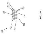
図10A~図12Bは、第2のプレート部分706と第1のプレート部分708とを有する加熱要素120の別の実施例を示しており、これらのプレート部分は、それらの間に毛管通路704を画定する複数の上方に延びる部材702を有する。毛管通路704は、上述したスパン128(例えば、毛管ギャップ)と同じまたは類似の特徴を有してもよい。10A-12B show another embodiment of a
図10Bに示したように、加熱要素120は、近位端部710と遠位端部712とを含み得る。近位端部710は、気化器カートリッジ52のリザーバ55と流体連通し得る。10B, the
第2のプレート部分706は、第2のプレート部分706の下端部かつ/または第2のプレート部分706の外面の少なくとも一部に沿って配置されたヒータ720Aのようなヒータを含み得る。いくつかの実施形態では、第2のプレート部分706は、別の方法で加熱されてヒータ領域を画定し得る。The
第1のプレート部分708と第2のプレート部分706とは一体に形成され得る。第1のプレート部分708は、複数の上方に向かって延在する部材702を含み得る。上方に向かって延在する部材702は、離間して配置されて、隣接する上方に向かって延在する部材702の間に延在する複数の通路704を画定し得る。通路704は、隣接する上方に向かって延在する部材702の間に形成された複数の毛管ギャップを画定し得る。毛管ギャップは、気化可能材料などの流体が、様々な向きで、隣接する上方に向かって延在する部材702の間で保持され、かつ/または、当該間のスペース内に引き込まれることを可能にし得る。気化可能材料は、例えば通路704を介した毛管作用によって、リザーバ55から加熱要素120のヒータ領域へと引き込まれてもよい。このような構成により、カートリッジ内の圧力を制御することが可能になり得る。The
上方に向かって延在する部材702は、並行であり得、ほぼ等しい幅の通路704を形成し得る。いくつかの構成では、通路704の幅は、流体の流れ方向に沿って変化し得る。図2A~図9に示されたスパン128に関して上述したように、通路704は、望ましくは、上方に向かって延在する部材702の間で、流体を吸引しかつ/または別の形式で保持するために、強くかつ/または十分な毛管力を維持するように狭くされ得る。例えば、通路704のサイズによって、通路704内で流体が補充される速度を制御してもよい。いくつかの実施形態では、好ましくは、通路704は、選択され、かつ/または、サイズ調整されて、気化可能材料が過度に迅速に通路704に出入りすることを制限または防止し得、かつ/または、気化可能材料を通路704内に保持し得る。いくつかの実施形態では、好ましくは、通路704のサイズは、選択され、かつ/または、サイズ調整されて、通路704に気化可能材料の十分な量を保持することを可能にし得、これにより、通路704がパフ中に補充される必要がなくなり、かつ/または、パフ中および/またはパフ後に容易に補充され得る。The upwardly extending
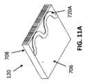
図12Aおよび図12Bに示したように、加熱要素120の位置は、ガスケット173またはその他のシール機構によって保持され得る。ガスケット173は、加熱要素120と一体かつ/または別個であり得る。ガスケット173は、ヒータ領域709を流体領域707から分離し得る。ガスケット173は、種々の材料、例えば特にシリコーンおよび/またはプラスチックを含むことができる。いくつかの実施形態において、ガスケット173は、通路704を通じた空気の戻りを可能にする薄さを有する。12A and 12B, the position of the
ユーザが気化器カートリッジ52のマウスピース21でパフするとき、空気は、入口106,116内へと、空気通路118に沿って流れる。ユーザのパフに伴って、加熱要素120は、例えば、圧力センサを介したパフの自動検出によって、ユーザによるボタンの押圧検出によって、モーションセンサ、フローセンサ、容量性リップセンサ、またはユーザがパフし又はパフしようとし或いはその他の形式で吸引して、空気を気化器デバイス100に進入させて最終的には空気通路118に沿って移動させていることを検出可能な他のアプローチから生成される信号によって、作動されてもよい。When a user puffs on the
加熱要素120が作動すると、加熱要素120に流れる電流により温度が上昇して発熱する。ヒータ120Aおよび/または加熱要素120には、リード714Aを介して電流が供給され得る。リード714Aは、気化器カートリッジ52の外部まで延在し得る。いくつかの実施形態では、ヒータ120Aおよび/または加熱要素120は、デバイスがリードレスであってよいように直接、または他の手段を介して電源に接続されてもよい。熱は、伝導性熱伝達、対流性熱伝達および/または放射性熱伝達を介して気化可能材料の所定量まで伝達され、それにより、気化可能材料の少なくとも一部が気化する。この熱伝達は、リザーバ内の気化可能材料、および/または、隣接する上方に向かって延在する部材702の間に形成された1つ以上の毛管通路704内に引き込まれた気化可能材料において起こり得る。加熱要素120と、毛管ギャップ内に存在する気化可能材料との間の熱伝達は、ヒータ領域で起こり得る。いくつかの実施形態では、気化可能材料は、加熱要素120のヒータ領域内において通路704を取り囲む1つ以上の縁部に沿って気化し得る。気化器デバイス100内を通過する空気は、空気通路118に沿ってアトマイザチャンバ110を通って流れ、気化した気化可能材料を通路704から離れさせる。気化した気化可能材料は、冷却や圧力変更などによって濃縮され得、ユーザが吸入するためのエアロゾルとしてマウスピース21から排出され得る。加熱要素120は、ニクロム、ステンレス鋼、または他の抵抗性ヒータ材料、プラスチック、および/またはセラミック材料、および/または他の多孔質材料のうちの1つ以上を含むが、これらに限定されない種々の材料から形成することができる。When the
図13Aは、加熱要素120の別の実施例を示しており、これは、内側プレート部分1224と、内側プレート部分1224を少なくとも部分的に取り囲んでもよい外側プレート部分1226とを含む。内側プレート部分および/または外側プレート部分1224,1226は、気化可能材料を加熱するための複数の穿孔1221(例えば図13Bを参照)および/または抵抗性トレースを含み得、気化可能材料を気化させ、これによりエアロゾルを生成する。いくつかの実施形態では、内側プレート部分および/または外側プレート部分1224,1226は、加熱要素120を加熱するための外面のような表面上に配置されたヒータ1220Aを含んでもよい(図13C参照)。13A illustrates another embodiment of a
外側プレート部分1226は、内側プレート部分1224を取り囲み得る。内側および外側プレート部分1224,1226は、円筒(図13Aに示されている)、長方形、正方形、または他の形状などの様々な形状であり得る。外側プレート部分1226は、内側プレート部分1224と平行に配置され得、また、毛管ギャップ1204を画定する(本明細書に記載されたスパン128と同じまたは類似の)スパンによって、内側プレート部分1224から離間し得る。例えば、図13に示された実施形態において、外側プレート部分1226および内側プレート部分1224は、同心の管または円筒を形成し得る。The
ユーザが気化器カートリッジ52のマウスピース21でパフすると、空気は、1つ以上の入口106へと空気通路118に沿って流れる。ユーザのパフに伴って、加熱要素120は、例えば、圧力センサを介したパフの自動検出によって、ユーザによるボタンの押圧検出によって、モーションセンサ、フローセンサ、容量性リップセンサ、またはユーザがパフし又はパフしようとし或いはその他の形式で吸引して、空気を気化器デバイス100に進入させて最終的には空気通路118に沿って移動させていることを検出可能な他のアプローチから生成される信号によって、作動されてもよい。When a user puffs on the
加熱要素120が作動すると、加熱要素120に流れる電流により温度が上昇して発熱する。熱は、伝導性熱伝達、対流性熱伝達および/または放射性熱伝達を介して気化可能材料の所定量まで伝達され、それにより、気化可能材料の少なくとも一部が気化する。この熱伝達は、リザーバ55内の気化可能材料、および/または、内側プレート部分1224と外側プレート部分1226との間に形成された毛管ギャップ1204内に引き込まれた気化可能材料において起こり得る。加熱要素120と、毛管ギャップ内に存在する気化可能材料との間の熱伝達は、ヒータ領域で起こり得る。いくつかの実施形態では、気化可能材料は、内側プレート部分および/または外側プレート部分1224,1226内の1つ以上の穿孔1221に沿って気化し得る。気化器デバイス100内を通過する空気は、空気通路118に沿ってアトマイザチャンバ110を通って流れ、気化した気化可能材料を加熱要素120から離れさせる。図13に示すように、空気通路は、外側プレート部分1226の外側の周囲に、かつ/または入口106を通って、また内側プレート部分1224によって画定された中央通路1202を通って、延在し得る。気化した気化可能材料は、冷却や圧力変更などによって濃縮され得、ユーザが吸入するためのエアロゾルとしてマウスピース21から排出される。加熱要素120は、ニクロム、ステンレス鋼、または他の抵抗性ヒータ材料、プラスチック、および/またはセラミック材料、および/または他の多孔質材料のうちの1つ以上を含むがこれらに限定されない種々の材料から形成することができる。When the
いくつかの実施形態では、加熱要素120は、セラミック材料および/または他の多孔質材料、例えば、限定されないが、金属、ガラス、炭素を含む高温耐性材料、および/または例えば、限定されないが、ポリフェニレンスルフィド(PPS)、液晶ポリマー(LCP)、またはポリエーテルエーテルケトン(PEEK)などの高温耐性プラスチック材料を含むことができる。多孔質材料は、リザーバから液体を吸収することを可能にする複数の空隙またはスペースを有することを特徴としてもよい。上述したように、加熱要素120は、1つ、2つ、またはそれより多数のプレートから形成され得る。いくつかの実施形態では、プレートは、加熱要素120の気化部122を加熱するための印刷されたヒータトレースを含み得る。このような構成は、他の利点の中でもとりわけ、製造性の向上および/または熱安定性の向上のために望ましい場合がある。いくつかの実施形態において、印刷されたヒータトレースを有するプレートのうちの少なくとも1つは、蒸気を排気することができる少なくとも1つの穿孔を含み得る。いくつかの実施形態では、加熱要素120は、穿孔を有する1つ以上のプレートと、印刷されたヒータトレースを有する1つ以上のプレートとを含むことができる。In some embodiments, the
印刷されたヒータトレースを有する加熱要素120の特定の実施形態では、トレースは、平行に、例えば加熱要素120の表面に沿って、より容易に配置され得る。このような加熱要素120の実施形態は、より高い抵抗率を有し得る。こうした実施形態により、加熱要素120にわたって電力をより効率的に分配し得、かつ/または加熱要素120全体にわたる温度差を低減し得る。In certain embodiments of the
印刷されたヒータトレースを有する加熱要素120の特定の実施形態では、加熱要素120のヒータトレースおよび/または構造は、同一でなくてもよい。こうした実施形態により、通気スリットを加熱要素の両端に支持することができ、かつ/または加熱要素により高い剛性を与えることができる。これにより、アトマイザチャンバ110および/または気化器カートリッジ52の周囲の機械的複雑さが単純化される場合がある。In certain embodiments of the
印刷されたヒータトレースを有する加熱要素120の特定の実施形態では、加熱要素120は低い熱伝導率を有することができ、これにより、場合によっては、より効率的な電力消費が可能となる。In certain embodiments of the
印刷されたヒータトレースを有する加熱要素120の特定の実施形態では、加熱要素120は、使用されない加熱要素の表面に沿ってより大きな領域を有し得る。こうした実施形態により、加熱要素120は、より小さな寸法を有することができる。こうした実施形態により、付加的な電子部品を加熱要素120上に配置することができる。In certain embodiments of the
本対象の実施形態に一致するアトマイザチャンバは、液体搬送容量を向上させているだけでなく、熱的に安定であり、気化器デバイス内での使用のために十分な構造的完全性を有している。Atomizer chambers consistent with embodiments of the present subject matter not only have improved liquid delivery capacity, but are also thermally stable and have sufficient structural integrity for use within vaporizer devices.
さらに、(例えば、トレースパターンの形態の)加熱要素に導電材料を使用することにより、抵抗熱係数(TCR)ベースの相関を利用して加熱要素の温度を制御し得る。より安定したTCRを達成し、結果として正確な温度センシング/制御を得るために、種々の導電性材料(例えば、ニッケル)を選択し、利用することができる。Furthermore, by using conductive materials for the heating elements (e.g., in the form of a trace pattern), a thermal coefficient of resistance (TCR) based correlation may be utilized to control the temperature of the heating elements. Various conductive materials (e.g., nickel) may be selected and utilized to achieve a more stable TCR and, as a result, accurate temperature sensing/control.
本対象の実施形態に一致するアトマイザコンポーネントは、図1A~図13Cの例示的な図に示した配向以外の配向を有してもよい。Atomizer components consistent with embodiments of the present subject matter may have orientations other than those shown in the exemplary illustrations of Figures 1A-13C.
図1A~図13Cに関して本明細書に記載している例は、取外し可能なカートリッジを使用する気化器を対象としているが、本対象の実施形態に一致するアトマイザチャンバは、そのようなデバイス構成に限定されない。例えば、アトマイザチャンバは、アトマイザおよび加熱要素が含まれるかまたは接触しているリザーバを含む気化器本体50の一部として組み込まれてもよい。Although the examples described herein with respect to Figures 1A-13C are directed to vaporizers that use removable cartridges, atomizer chambers consistent with embodiments of the present subject matter are not limited to such device configurations. For example, the atomizer chamber may be incorporated as part of the
図14を参照すると、工程フロー図1300は、以下のステップのうちの一部もしくはすべてをオプションとして含んでもよい方法の特徴を示している。ブロック1310において、毛管ギャップを画定するスパンによって分離された2つ以上の剛体部分を有する加熱要素が提供されてもよい。1320において、毛管ギャップの第1の端部と気化可能材料のリザーバとの間に流体連通を生じさせてもよい。1330において、毛管作用を介して、加熱要素の2つの剛体部分の間に形成された毛管ギャップに気化可能材料が引き込まれてもよい。1340において、毛管ギャップの第2の端部に加熱手段を設けてもよい。例えば、1350では、加熱要素の少なくとも一部が例えば毛管ギャップの第2の端部において加熱されてもよい。加熱により、気化可能材料の気化が起こる。ブロック1360において、気化された気化可能材料は、加熱要素が配置されている気化器デバイスのマウスピースに向かう空気流に混入される。Referring to FIG. 14, process flow diagram 1300 illustrates features of a method that may optionally include some or all of the following steps: At
用語
ある特徴または要素が、本明細書において別の特徴または要素の「上」にあるものとして言及される場合、その特徴または要素は、他の特徴または要素のすぐ上にあるものとすることができるし、あるいは介在する特徴および/または要素が存在してもよい。これとは対照的に、ある特徴または要素が、別の特徴または要素の「すぐ上」にあるものとして言及される場合、介在する特徴または要素は存在しない。また、ある特徴または要素が、別の特徴または要素に「接続されている」、「取り付けられている」、または「連結されている」ものとして言及される場合、その特徴または要素は、他の特徴または要素に直接、接続することができ、取り付けることができ、または連結することができるし、あるいは介在する特徴または要素が存在してもよいことは理解されるであろう。これとは対照的に、ある特徴または要素が、別の特徴または要素に「直接接続されている」、「直接取り付けられている」、または「直接連結されている」ものとして言及される場合、介在する特徴または要素は存在しない。 Terminology When a feature or element is referred to herein as being "on" another feature or element, the feature or element can be directly on the other feature or element, or there may be intervening features and/or elements. In contrast, when a feature or element is referred to as being "directly on" another feature or element, there are no intervening features or elements. Also, when a feature or element is referred to as being "connected,""attached," or "coupled" to another feature or element, it will be understood that the feature or element can be directly connected, attached, or coupled to the other feature or element, or there may be intervening features or elements. In contrast, when a feature or element is referred to as being "directly connected,""directlyattached," or "directly coupled" to another feature or element, there are no intervening features or elements.
1つの実施例に関して説明または図示されているが、そのように説明または図示された特徴および要素は、他の実施例にも適用可能である。また、別の特徴に「隣接して」配置された構造または特徴に関する言及は、隣接する特徴と重なり合う部分またはその下にある部分を有する場合もあることが、当業者には理解されるであろう。Although described or illustrated with respect to one embodiment, the features and elements so described or illustrated may be applicable to other embodiments. Additionally, those skilled in the art will understand that references to structures or features being located "adjacent" to another feature may have portions that overlap or underlie the adjacent feature.
本明細書で使用される用語は、特定の実施例および実施形態のみを説明する目的で使用されており、限定することを意図していない。例えば本明細書で用いられる単数形の不定冠詞および定冠詞は、文脈から明確に別段の指示がない限りは、複数形も同様に含むことを意図している。本明細書において使用される場合、用語「を含む」および/または「を含んでいる」は、記載された特徴、ステップ、オペレーション、要素および/または構成要素の存在を指定するが、それらの1つ以上の他の特徴、ステップ、オペレーション、要素、構成要素および/またはそのグループの存在または追加を除外するものではないことをさらに理解されたい。本明細書において使用されるとき、「および/または」という用語は、関連する列挙された項目のうちの1つ以上の任意のおよびすべての組合せを含み、「/」と省略することができる。The terms used herein are used for the purpose of describing only certain examples and embodiments and are not intended to be limiting. For example, the singular indefinite and definite articles used herein are intended to include the plural as well, unless the context clearly indicates otherwise. It is further understood that, as used herein, the terms "comprises" and/or "comprising" specify the presence of the stated features, steps, operations, elements and/or components, but do not exclude the presence or addition of one or more other features, steps, operations, elements, components and/or groups thereof. As used herein, the term "and/or" includes any and all combinations of one or more of the associated listed items and may be abbreviated as "/".
上記の説明および特許請求の範囲において、「のうちの少なくとも1つ」または「のうちの1つまたは複数」などの語句が、要素または特徴の連言的なリストに続いて現れる場合がある。「および/または」という用語は、2つ以上の要素または特徴のリスト中に現れる場合もある。使用された文脈によって他のやり方で暗黙的もしくは明示的に否定されない限り、そのような語句は、列挙された要素または特徴のいずれかを個別に意味すること、あるいは列挙された要素または特徴のいずれかと他の列挙された要素または特徴のいずれかとの組合せを意味することを意図している。例えば、「AおよびBのうちの少なくとも1つ」、「AおよびBのうちの1つ以上」、ならびに「Aおよび/またはB」との語句は、それぞれ、「Aのみ、Bのみ、またはAおよびBともに」を意味することを意図している。3つ以上の項目を含むリストについても同様の解釈が意図されている。例えば、「A、BおよびCのうちの少なくとも1つ」、「A、BおよびCのうちの1つ以上」、ならびに「A、Bおよび/またはC」との語句は、それぞれ、「Aのみ、Bのみ、Cのみ、AおよびBともに、AおよびCともに、BおよびCともに、またはAおよびBおよびCともに」を意味することを意図している。これまでの記載および特許請求の範囲における用語「に基づく」の使用は、列挙されていない特徴または要素も許容されるように、「に少なくとも部分的に基づく」を意味することを意図している。In the above description and in the claims, phrases such as "at least one of" or "one or more of" may appear following a conjunctive list of elements or features. The term "and/or" may also appear in a list of two or more elements or features. Unless otherwise implicitly or explicitly denied by the context in which it is used, such phrases are intended to mean any of the listed elements or features individually, or any of the listed elements or features in combination with any of the other listed elements or features. For example, the phrases "at least one of A and B," "one or more of A and B," and "A and/or B" are intended to mean "A only, B only, or both A and B," respectively. A similar interpretation is intended for lists containing more than two items. For example, the phrases "at least one of A, B, and C," "one or more of A, B, and C," and "A, B, and/or C" are intended to mean "A only, B only, C only, both A and B, both A and C, both B and C, or both A, B, and C," respectively. Use of the term "based on" in the description above and in the claims is intended to mean "based at least in part on," allowing for unrecited features or elements.
「上部」、「下部」、「下方に」、「下側に」、「下部に」、「上方に」、「上部に」およびこれらに類するものなどの空間的に相対的な用語が、図面に示されているような1つの要素または特徴と、他の要素または特徴との関係を説明するための記述を容易にするために、本明細書において使用されてよい。空間的に相対的な用語が、図面に描かれている配向に加え、使用時または動作時におけるデバイスの様々な配向を包含することを意図していることは理解されるであろう。例えば、図中のデバイスが反転されたならば、その場合には他の要素または特徴の「下方に」または「真下に」と記載された要素は、他の要素または特徴の「上方に」配向されることになる。したがって、例として挙げた用語「の下方に」は、上方と下方との配向の双方を包含し得るものである。デバイスは(90度回転させられるかまたは他の配向で)別の向きで配向されてよく、本明細書で使用される空間的に相対する記述もそれに応じて解釈され得る。同様に、用語「上方に向かって」、「下方に向かって」、「垂直に」、「水平に」およびこれらに類するものは、具体的に別段の指示がない限りは、本明細書では説明の目的で用いられるにすぎない。Spatially relative terms such as "top", "bottom", "down", "below", "below side", "lower", "up", "above" and the like may be used herein to facilitate description to describe the relationship of one element or feature to another element or feature as shown in the drawings. It will be understood that the spatially relative terms are intended to encompass various orientations of the device in use or operation in addition to the orientation depicted in the drawings. For example, if the device in the drawings were inverted, then an element described as "below" or "directly below" the other element or feature would be oriented "above" the other element or feature. Thus, the exemplary term "below" can encompass both an upward and downward orientation. The device may be otherwise oriented (rotated 90 degrees or in other orientations) and the spatially relative descriptions used herein may be interpreted accordingly. Similarly, the terms "upward", "downward", "vertically", "horizontally" and the like are used herein for descriptive purposes only, unless specifically indicated otherwise.
本明細書では、様々な特徴/要素(ステップを含む)を説明するために用語「第1の」および「第2の」が用いられる場合があるが、これらの特徴/要素は、文脈が別段の指示をしない限り、これらの用語によって限定されるものではない。これらの用語は、1つの特徴/要素を別の特徴/要素から区別するために使用することができる。したがって、本明細書で提供される教示から逸脱することなく、以下で述べる第1の特徴/要素は、第2の特徴/要素と称することができ、同様に、以下で述べる第2の特徴/要素は、第1の特徴/要素と称することができる。Although the terms "first" and "second" may be used herein to describe various features/elements (including steps), these features/elements are not limited by these terms unless the context dictates otherwise. These terms may be used to distinguish one feature/element from another. Thus, without departing from the teachings provided herein, a first feature/element described below may be referred to as a second feature/element, and similarly, a second feature/element described below may be referred to as a first feature/element.
実施例において使用される場合を含め、特に別段の指定がない限りは、本明細書および特許請求の範囲において使用されているすべての数は、「約」または「ほぼ」といった単語が、たとえこれらの用語が明確に現れていないにしても、前置きされているかのように読むことができる。大きさおよび/または位置を説明する場合、これらの「約」または「ほぼ」という語句は、記載される値および/または位置が、当該値および/または位置の妥当な予測範囲内にあることを示すために使用される場合がある。例えば、数値は、所定値(または値の範囲)の+/-0.1%、所定値(または値の範囲)の+/-1%、所定値(または値の範囲)の+/-2%、所定値(または値の範囲)の+/-5%、所定値(または値の範囲)の+/-10%などの値を含むことができる。本明細書で与えられる任意の数値は、文脈により別段の指定がない限り、その値の付近の、またはほぼ同じ値を含むものと理解されたい。例えば値「10」が開示されているならば、その場合には「約10」も開示されている。本明細書で挙げられているいずれの数値範囲も、その中に包含されるすべての部分範囲を含むことを意図している。また、ある値が開示されている場合には、当業者が適切に理解するように、その値「以下」、「その値以上」、およびそれらの値の間の可能な範囲も開示されていることが理解されよう。例えば、値「X」が開示されているならば、「X以下」ならびに「X以上」(例えば、Xは数値)も開示されている。また、本出願全体を通して、データが多くの異なる形式で提供されていること、ならびにこのデータは、終了点および開始点、およびこれらのデータ点の任意の組合せに関する範囲を表すことが理解されよう。例えば、特定のデータポイント「10」および特定のデータポイント「15」が開示されているならば、10および15より大きい、10および15以上の、10および15より小さい、10および15以下の、ならびに10および15と等しいことも、10と15との間の範囲と同様に開示されていると見なされることが理解されよう。また、2つの特定のユニット間の各ユニットも開示されているということも理解される。例えば10および15が開示されているならば、その場合には11、12、13および14も開示されている。Unless otherwise specified, including when used in the examples, all numbers used in this specification and claims can be read as if they are preceded by the words "about" or "approximately" even if these terms do not explicitly appear. When describing a size and/or location, these words "about" or "approximately" may be used to indicate that the stated value and/or location is within a reasonable expected range of that value and/or location. For example, a numerical value may include values such as +/-0.1% of a given value (or range of values), +/-1% of a given value (or range of values), +/-2% of a given value (or range of values), +/-5% of a given value (or range of values), +/-10% of a given value (or range of values), etc. Any numerical value given herein should be understood to include values near or about that value unless otherwise specified by context. For example, if the value "10" is disclosed, then "about 10" is also disclosed. Any numerical ranges recited herein are intended to include all subranges subsumed therein. It is also understood that where a value is disclosed, "less than or equal to" that value, "more than or equal to" that value, and possible ranges between those values are also disclosed, as would be understood by one of ordinary skill in the art. For example, if a value "X" is disclosed, "less than or equal to X" and "more than or equal to X" (e.g., X is a number) are also disclosed. It is also understood that throughout this application, data is provided in many different formats, and that this data represents end and starting points, and ranges for any combination of those data points. For example, if a specific data point "10" and a specific data point "15" are disclosed, it is understood that greater than 10 and 15, greater than or equal to 10 and 15, less than 10 and 15, less than or equal to 10 and 15, and equal to 10 and 15 are also considered to be disclosed, as is the range between 10 and 15. It is also understood that each unit between two specific units is also disclosed. For example, if 10 and 15 are disclosed, then 11, 12, 13, and 14 are also disclosed.
様々な例示的な実施例を上述したが、本明細書の教示から逸脱することなく、様々な実施例に対して多数の変更のいずれかを行うことができる。例えば、記載された様々な方法ステップが実行される順序は、代替的な実施例では多くの場合、変更されてもよく、他の代替的な実施形態では、1つ以上の方法ステップが完全にスキップされてもよい。様々なデバイスおよびシステムの実施例のオプションとしての特徴は、いくつかの実施例には含まれ、他の実施例には含まれなくてもよい。したがって、前述の説明は、主に例示の目的で提供されており、特許請求の範囲を限定するものと解釈されるべきではない。Although various illustrative examples have been described above, any of a number of modifications may be made to the various examples without departing from the teachings herein. For example, the order in which the various method steps described are performed may often be changed in alternative examples, and in other alternative embodiments, one or more method steps may be skipped entirely. Optional features of the various device and system examples may be included in some examples and not included in others. Thus, the foregoing description has been provided primarily for illustrative purposes and should not be construed as limiting the scope of the claims.
本明細書に記載された対象の1つ以上の態様または特徴は、デジタル電子回路、集積回路、特別に設計された特定用途向け集積回路(ASIC)、フィールドプログラマブルゲートアレイ(FPGA)、コンピュータハードウェア、ファームウェア、ソフトウェア、および/またはこれらの組合せにおいて実現することができる。これらの様々な態様または特徴は、特別または汎用的であり得る少なくとも1つのプログラマブルプロセッサを含むプログラマブルシステム上で実行可能および/または解釈可能な1つ以上のコンピュータプログラムへの実装を含むことができ、当該プログラマブルプロセッサは、ストレージシステム、少なくとも1つの入力デバイスおよび少なくとも1つの出力デバイスからデータおよび命令を受信および送信するように連結される。プログラマブルシステムまたはコンピューティングシステムは、クライアントおよびサーバを含むことができる。クライアントおよびサーバは概して互いにリモートの状態にあり、通常、通信ネットワークを介して相互作用する。クライアントおよびサーバの関係は、個々のコンピュータ上で実行され、クライアント-サーバ関係を相互に有するコンピュータプログラムによって発生する。One or more aspects or features of the subject matter described herein may be implemented in digital electronic circuitry, integrated circuits, specially designed application specific integrated circuits (ASICs), field programmable gate arrays (FPGAs), computer hardware, firmware, software, and/or combinations thereof. These various aspects or features may include implementation in one or more computer programs executable and/or interpretable on a programmable system including at least one programmable processor, which may be specialized or general purpose, coupled to receive and transmit data and instructions from a storage system, at least one input device, and at least one output device. The programmable system or computing system may include clients and servers. The clients and servers are generally remote from each other and typically interact through a communications network. The relationship of client and server arises by virtue of computer programs running on respective computers and having a client-server relationship to each other.
プログラム、ソフトウェア、ソフトウェアアプリケーション、アプリケーション、コンポーネント、またはコードとも呼ぶことができるこれらのコンピュータプログラムは、プログラマブルプロセッサのための機械命令を含み、高水準手続き型言語、オブジェクト指向プログラミング言語、関数型プログラミング言語、論理プログラミング言語、および/またはアセンブリ/機械語で実施することができる。本明細書で使用されるときに、「機械可読媒体」の用語は、機械可読信号としての機械命令を受け取る機械可読媒体を含め、プログラム可能なプロセッサに機械命令および/またはデータを提供するために使用される、例えば磁気ディスク、光ディスク、メモリ、およびプログラマブルロジックデバイス(PLD)などの任意のコンピュータプログラム製品、装置、および/またはデバイスを指す。「機械可読信号」の用語は、機械命令および/またはデータをプログラマブルプロセッサに供給するために使用される任意の信号のことを指す。この機械可読媒体は、そのような機械命令を、例えば非一時的なソリッドステートメモリもしくは磁気ハードドライブまたは任意の同等の記憶媒体などのように非一時的に記憶することができる。機械可読媒体は、代替的または付加的に、そのような機械命令を、例えばプロセッサキャッシュかまたは1つ以上の物理プロセッサコアに関連付けられた他のランダムアクセスメモリなどのように一時的に記憶することができる。These computer programs, which may also be referred to as programs, software, software applications, applications, components, or codes, contain machine instructions for a programmable processor and may be implemented in high-level procedural languages, object-oriented programming languages, functional programming languages, logic programming languages, and/or assembly/machine languages. As used herein, the term "machine-readable medium" refers to any computer program product, apparatus, and/or device, such as, for example, magnetic disks, optical disks, memories, and programmable logic devices (PLDs), used to provide machine instructions and/or data to a programmable processor, including a machine-readable medium that receives machine instructions as a machine-readable signal. The term "machine-readable signal" refers to any signal used to provide machine instructions and/or data to a programmable processor. The machine-readable medium may store such machine instructions non-temporarily, such as, for example, a non-temporary solid-state memory or a magnetic hard drive or any equivalent storage medium. The machine-readable medium may alternatively or additionally store such machine instructions temporarily, such as, for example, a processor cache or other random access memory associated with one or more physical processor cores.
本明細書に含まれる実施例および図面は、限定としてではなく例示として、本対象を実施することができる特定の実施例を示している。上述のように、本開示の範囲から逸脱することなく構造的および論理的な置き換えおよび変更を行うことができるように、他の実施形態を利用することができ、そこから導き出すことができる。本発明の対象のこうした実施例は、2つ以上が実際に開示されているならば、単に便宜上「発明」という用語によって本明細書では個別にもしくは集約的に言及することができ、この出願の範囲を任意の単一の発明または発明概念に自発的に限定することを意図するものではない。したがって、本明細書では特定の実施形態を図示および説明してきたが、同じ目的を達成するために計算されたあらゆる配置を、図示された特定の実施形態に置き換えることができる。本開示は、様々な実施例の任意のおよびすべての適応形態または変形形態をカバーすることを意図している。上述の実施例と、本明細書に具体的に記載されていない他の実施例との組合せは、上述の説明を精査すれば、当業者には明らかになるであろう。The examples and figures contained herein illustrate, by way of illustration and not by way of limitation, specific examples in which the subject matter may be practiced. As noted above, other embodiments may be utilized and derived therefrom, such that structural and logical substitutions and changes may be made without departing from the scope of the present disclosure. Such examples of the subject matter of the present invention may be referred to herein, individually or collectively, by the term "invention" merely for convenience, if more than one is actually disclosed, and are not intended to spontaneously limit the scope of this application to any single invention or inventive concept. Thus, while specific embodiments have been illustrated and described herein, any arrangement calculated to achieve the same purpose may be substituted for the specific embodiments illustrated. The present disclosure is intended to cover any and all adaptations or variations of the various examples. Combinations of the above-described examples with other examples not specifically described herein will be apparent to those of skill in the art upon review of the above description.
Claims (20)
Translated fromJapanese気化可能材料を保持するように構成されたリザーバと、
前記気化可能材料を加熱するように構成された加熱要素と、を備え、前記加熱要素は、
複数の剛体部分を流れる電流により発熱するように構成された前記複数の剛体部分を含む毛管構造を有しており、
前記複数の剛体部分の対は、互いに離間してその間に毛管ギャップを画定し、前記毛管ギャップは、前記気化可能材料を加熱するために、前記気化可能材料を前記リザーバから前記加熱要素のヒータ領域に引き込むように構成されていて、前記加熱要素の前記ヒータ領域に引き込まれた前記気化可能材料の加熱によりエアロゾルが生成される、
気化器デバイス用のカートリッジ。 1. A cartridge for a vaporizer device, the cartridge comprising:
a reservoir configured to hold a vaporizable material;
a heating element configured to heat the vaporizable material, the heating element comprising:
a capillary structure including a plurality of rigid portions configured to generate heat by passing an electric current through the plurality of rigid portions;
a pair of the plurality of rigid portions spaced apart from one another to define a capillary gap therebetween, the capillary gap being configured to draw the vaporizable material from the reservoir to a heater region of the heating element for heating the vaporizable material, wherein heating the vaporizable material drawn into the heater region of the heating element generates an aerosol.
Cartridges for vaporizer devices.
上部剛体部分と、
前記上部剛体部分に一体に形成された下部剛体部分と、を有していて、前記下部剛体部分は、前記毛管ギャップを画定するスパンによって前記上部剛体部分から離間している、
請求項1記載のカートリッジ。 The plurality of rigid portions of the capillary structure include
An upper rigid portion;
a lower rigid portion integrally formed with said upper rigid portion, said lower rigid portion being spaced from said upper rigid portion by a span that defines said capillary gap.
2. The cartridge of claim 1.
前記リザーバと流体連通するように構成された上端部と、
ヒータを備えた下端部と、
下部剛体部分と、
前記下部剛体部分に一体に形成された上部剛体部分と、を有していて、前記上部剛体部分は、
複数の上方に向かって延在する部材を有しており、
前記毛管ギャップは、前記複数の上方に向かって延在する部材のうち隣接する上方に向かって延在する部材の間に形成されている、
請求項1記載のカートリッジ。 The plurality of rigid portions of the capillary structure include
a top end configured to be in fluid communication with the reservoir;
a lower end portion provided with a heater;
A lower rigid portion;
an upper rigid portion integrally formed with the lower rigid portion, the upper rigid portion comprising:
a plurality of upwardly extending members;
the capillary gap is formed between adjacent upwardly extending members of the plurality of upwardly extending members.
2. The cartridge of claim 1.
中央通路を画定する内側プレート部分と、
前記内側プレート部分を取り囲む外側プレート部分と、を有していて、前記外側プレート部分は、前記毛管ギャップを画定するスパンによって前記内側プレート部分から離間している、
請求項1記載のカートリッジ。 The plurality of rigid portions of the capillary structure include
an inner plate portion defining a central passage;
an outer plate portion surrounding the inner plate portion, the outer plate portion being spaced from the inner plate portion by a span that defines the capillary gap.
2. The cartridge of claim 1.
気化器デバイス本体と、
請求項1記載のカートリッジと、
を有している、気化器デバイス。 1. A vaporizer device comprising:
A vaporizer device body;
A cartridge according to claim 1;
The vaporizer device comprises:
気化可能材料を保持するように構成されたリザーバと、
前記気化可能材料を加熱するように構成された加熱要素と、を備え、前記加熱要素は、
複数の剛体部分を流れる電流により発熱するように構成された前記複数の剛体部分を含む毛管構造を有しており、
前記複数の剛体部分の対は、互いに離間してその間に毛管ギャップを画定し、前記毛管ギャップは、前記気化可能材料を加熱するために、前記気化可能材料を前記リザーバから前記加熱要素のヒータ領域に引き込むように構成されていて、前記加熱要素の前記ヒータ領域に引き込まれた前記気化可能材料の加熱によりエアロゾルが生成される、
気化器デバイス。 1. A vaporizer device comprising:
a reservoir configured to hold a vaporizable material;
a heating element configured to heat the vaporizable material, the heating element comprising:
a capillary structure including a plurality of rigid portions configured to generate heat by passing an electric current through the plurality of rigid portions;
a pair of the plurality of rigid portions spaced apart from one another to define a capillary gap therebetween, the capillary gap being configured to draw the vaporizable material from the reservoir to a heater region of the heating element for heating the vaporizable material, wherein heating the vaporizable material drawn into the heater region of the heating element generates an aerosol.
Vaporizer device.
上部剛体部分と、
前記上部剛体部分に一体に形成された下部剛体部分と、を有していて、前記下部剛体部分は、前記毛管ギャップを画定するスパンによって前記上部剛体部分から離間している、
請求項17記載の気化器デバイス。 The plurality of rigid portions of the capillary structure include
An upper rigid portion;
a lower rigid portion integrally formed with said upper rigid portion, said lower rigid portion being spaced from said upper rigid portion by a span that defines said capillary gap.
20. The vaporizer device of claim 17.
前記リザーバと流体連通するように構成された上端部と、
ヒータを備えた下端部と、
下部剛体部分と、
前記下部剛体部分に一体に形成された上部剛体部分と、を有していて、前記上部剛体部分は、
上方に向かって延在する複数の部材を有しており、
前記毛管ギャップは、前記複数の上方に向かって延在する部材のうち隣接する上方に向かって延在する部材の間に形成されている、
請求項17記載の気化器デバイス。 The plurality of rigid portions of the capillary structure include
a top end configured to be in fluid communication with the reservoir;
a lower end portion provided with a heater;
A lower rigid portion;
an upper rigid portion integrally formed with the lower rigid portion, the upper rigid portion comprising:
The device has a plurality of members extending upward,
the capillary gap is formed between adjacent upwardly extending members of the plurality of upwardly extending members.
20. The vaporizer device of claim 17.
前記2つの剛体部分の少なくとも前記気化部を加熱して、前記気化可能材料を気化させるステップと、
前記気化器デバイスのマウスピースへの空気流路に沿った空気流に気化した前記気化可能材料を混入させるステップと、
を有し、
前記加熱要素は、前記剛体部分に流れる電流により発熱する、方法。 drawing vaporizable material from a reservoir of a vaporizer device to a heater region through a capillary gap formed between two rigid portions of a heating element, the heating element being partially located within at least a portion of the reservoir, each of the two rigid portions having a vaporizing portion;
heating at least the vaporization portions of the two rigid portions to vaporize the vaporizable material;
mixing the vaporized vaporizable material with an airflow along an airflow path to a mouthpiece of the vaporizer device;
having
The method of claim 1, wherein the heating element is heated by an electrical current passing through the rigid portion.
Priority Applications (1)
| Application Number | Priority Date | Filing Date | Title |
|---|---|---|---|
| JP2025016919AJP2025069359A (en) | 2018-10-08 | 2025-02-04 | Heating elements |
Applications Claiming Priority (3)
| Application Number | Priority Date | Filing Date | Title |
|---|---|---|---|
| US201862742554P | 2018-10-08 | 2018-10-08 | |
| US62/742,554 | 2018-10-08 | ||
| PCT/US2019/055254WO2020076864A1 (en) | 2018-10-08 | 2019-10-08 | Heating element |
Related Child Applications (1)
| Application Number | Title | Priority Date | Filing Date |
|---|---|---|---|
| JP2025016919ADivisionJP2025069359A (en) | 2018-10-08 | 2025-02-04 | Heating elements |
Publications (2)
| Publication Number | Publication Date |
|---|---|
| JP2022508658A JP2022508658A (en) | 2022-01-19 |
| JP7630432B2true JP7630432B2 (en) | 2025-02-17 |
Family
ID=68343526
Family Applications (2)
| Application Number | Title | Priority Date | Filing Date |
|---|---|---|---|
| JP2021544113AActiveJP7630432B2 (en) | 2018-10-08 | 2019-10-08 | Heating elements |
| JP2025016919APendingJP2025069359A (en) | 2018-10-08 | 2025-02-04 | Heating elements |
Family Applications After (1)
| Application Number | Title | Priority Date | Filing Date |
|---|---|---|---|
| JP2025016919APendingJP2025069359A (en) | 2018-10-08 | 2025-02-04 | Heating elements |
Country Status (9)
| Country | Link |
|---|---|
| US (2) | US12058786B2 (en) |
| EP (2) | EP4487715A3 (en) |
| JP (2) | JP7630432B2 (en) |
| KR (2) | KR20250048483A (en) |
| CN (2) | CN111067144A (en) |
| AR (1) | AR116723A1 (en) |
| CA (1) | CA3115519A1 (en) |
| FR (1) | FR3086845B1 (en) |
| WO (1) | WO2020076864A1 (en) |
Families Citing this family (29)
| Publication number | Priority date | Publication date | Assignee | Title |
|---|---|---|---|---|
| EP3675661B1 (en) | 2017-08-28 | 2023-06-07 | Juul Labs, Inc. | Wick for vaporizer device |
| EP3813914B1 (en) | 2018-06-26 | 2023-10-25 | Juul Labs, Inc. | Vaporizer wicking elements |
| CN110754696A (en) | 2018-07-23 | 2020-02-07 | 尤尔实验室有限公司 | Airflow management for evaporator units |
| CN119632302A (en) | 2018-07-31 | 2025-03-18 | 尤尔实验室有限公司 | Cartridge-based heat-without-burn vaporizer |
| SG11202103757VA (en) | 2018-10-15 | 2021-05-28 | Juul Labs Inc | Heating element |
| US12256784B2 (en) | 2018-10-17 | 2025-03-25 | Juul Labs, Inc. | Cartridge for a vaporizer device |
| GB2613472B (en) | 2018-10-19 | 2023-09-06 | Juul Labs Inc | Vaporizer power system |
| EP3876763B1 (en) | 2018-11-05 | 2022-12-28 | Juul Labs, Inc. | A cartridge for a vaporizer device |
| ES2932748T3 (en) | 2018-11-05 | 2023-01-25 | Juul Labs Inc | Cartridges for vaporizer devices |
| US11553734B2 (en) | 2018-11-08 | 2023-01-17 | Juul Labs, Inc. | Cartridges for vaporizer devices |
| CN113226078B (en) | 2018-12-21 | 2024-10-18 | 尤尔实验室有限公司 | Evaporator device |
| WO2020154690A1 (en) | 2019-01-25 | 2020-07-30 | Juul Labs, Inc. | Vaporizer device and cartridge |
| US11253001B2 (en) | 2019-02-28 | 2022-02-22 | Juul Labs, Inc. | Vaporizer device with vaporizer cartridge |
| WO2020205561A1 (en) | 2019-03-29 | 2020-10-08 | Juul Labs, Inc. | Cartridges for vaporizer devices |
| CN210203316U (en)* | 2019-05-07 | 2020-03-31 | 深圳市合元科技有限公司 | Cigarette bullet and electron cigarette |
| EP3983035B1 (en)* | 2019-06-12 | 2025-05-28 | Juul Labs, Inc. | Vaporizable material insert for vaporizer device |
| US11458262B2 (en)* | 2019-06-25 | 2022-10-04 | Altria Client Services Llc | Capsules, heat-not-burn (HNB) aerosol-generating devices, and methods of generating an aerosol |
| CN110226777B (en)* | 2019-06-27 | 2025-02-11 | 深圳雾芯科技有限公司 | Electronic atomizer, electronic atomizer device body and electronic atomizer device |
| JP7614175B2 (en) | 2019-08-08 | 2025-01-15 | ジュール・ラブズ・インコーポレイテッド | Vaporizable material insert for vaporizer device |
| JP7246782B2 (en)* | 2020-09-15 | 2023-03-28 | 深▲ゼン▼市華誠達精密工業有限公司 | Liquid introduction cotton atomization unit |
| US12426630B2 (en)* | 2020-12-10 | 2025-09-30 | Blackship Technologies Development Llc | Disposable vaporizer cartridge |
| US20220183361A1 (en)* | 2020-12-10 | 2022-06-16 | Blackship Technologies Development Llc | Thin plate heating elements for micro-vaporizers |
| WO2022178092A1 (en)* | 2021-02-19 | 2022-08-25 | Dynavap, LLC | Assembly for thermal extraction device and thermal extraction device |
| CN115067564A (en)* | 2021-03-16 | 2022-09-20 | 深圳市合元科技有限公司 | Electronic atomization device, power supply mechanism and atomizer identification method |
| AU2023207061A1 (en)* | 2022-01-12 | 2024-08-22 | Aether Innovations, Llc | Personal vaporizing unit |
| US20240148060A1 (en)* | 2022-09-19 | 2024-05-09 | Altria Client Services Llc | Heat-not-burn (hnb) aerosol-generating devices and capsules having electrical contact pads with surface discontinuities |
| USD1051071S1 (en) | 2022-11-07 | 2024-11-12 | Altria Client Services Llc | Set of electrical contact pads |
| KR20250131815A (en)* | 2023-01-19 | 2025-09-03 | 제이티 인터내셔널 소시에떼 아노님 | Aerosol generating device comprising two heating plates |
| KR20250131799A (en)* | 2023-01-19 | 2025-09-03 | 제이티 인터내셔널 소시에떼 아노님 | An aerosol generating device configured to operate with an aerosol generating device. |
Citations (5)
| Publication number | Priority date | Publication date | Assignee | Title |
|---|---|---|---|---|
| CN104544567A (en) | 2014-12-24 | 2015-04-29 | 深圳市麦克韦尔科技有限公司 | Electronic cigarette |
| EP3216359A1 (en) | 2016-05-27 | 2017-09-13 | Shenzhen First Union Technology Co., Ltd. | Atomizer and electronic cigarette having same |
| WO2018007633A1 (en) | 2016-07-07 | 2018-01-11 | Philip Morris Products S.A. | Non-combustible vaping element with tobacco insert |
| WO2018172765A1 (en) | 2017-03-24 | 2018-09-27 | Nicoventures Holdings Limited | Aerosol source for a vapour provision system |
| JP2020521434A (en) | 2017-03-29 | 2020-07-27 | アール・エイ・アイ・ストラテジック・ホールディングス・インコーポレイテッド | Aerosol delivery device comprising a substrate having improved absorption properties |
Family Cites Families (224)
| Publication number | Priority date | Publication date | Assignee | Title |
|---|---|---|---|---|
| US5666977A (en) | 1993-06-10 | 1997-09-16 | Philip Morris Incorporated | Electrical smoking article using liquid tobacco flavor medium delivery system |
| KR100289448B1 (en)* | 1997-07-23 | 2001-05-02 | 미즈노 마사루 | Flavor generator |
| US6501052B2 (en) | 2000-12-22 | 2002-12-31 | Chrysalis Technologies Incorporated | Aerosol generator having multiple heating zones and methods of use thereof |
| US6568390B2 (en) | 2001-09-21 | 2003-05-27 | Chrysalis Technologies Incorporated | Dual capillary fluid vaporizing device |
| US6640050B2 (en) | 2001-09-21 | 2003-10-28 | Chrysalis Technologies Incorporated | Fluid vaporizing device having controlled temperature profile heater/capillary tube |
| US7458373B2 (en) | 2002-01-15 | 2008-12-02 | Philip Morris Usa Inc. | Aerosol generator for drug formulation |
| AU2003222642A1 (en) | 2002-05-10 | 2003-11-11 | Chrysalis Technologies Incorporated | Aerosol generator for drug formulation and methods of generating aerosol |
| AU2003270320B2 (en) | 2002-09-06 | 2008-10-23 | Philip Morris Products S.A. | Aerosol generating device and method of use thereof |
| CN1700934B (en) | 2002-09-06 | 2011-08-03 | 菲利普莫里斯美国公司 | Liquid aerosol preparation and aerosol generating device and method for preparing aerosol |
| US7683029B2 (en) | 2003-05-07 | 2010-03-23 | Philip Morris Usa Inc. | Liquid aerosol formulations containing insulin and aerosol generating devices and methods for generating aerosolized insulin |
| CN1846051A (en) | 2003-07-01 | 2006-10-11 | 蒂艾克思股份有限公司 | Recuperators and combustion chambers for external combustion engines and systems using them to generate electricity |
| US7367334B2 (en) | 2003-08-27 | 2008-05-06 | Philip Morris Usa Inc. | Fluid vaporizing device having controlled temperature profile heater/capillary tube |
| CN2719043Y (en) | 2004-04-14 | 2005-08-24 | 韩力 | Atomized electronic cigarette |
| ES2559410T3 (en) | 2004-04-23 | 2016-02-12 | Philip Morris Products S.A. | Aerosol generators and methods for producing aerosols |
| US7167776B2 (en)* | 2004-09-02 | 2007-01-23 | Philip Morris Usa Inc. | Method and system for controlling a vapor generator |
| US9604016B2 (en) | 2006-01-31 | 2017-03-28 | Philip Morris Usa Inc. | Bent capillary tube aerosol generator |
| US8371310B2 (en)* | 2006-02-17 | 2013-02-12 | Jake Brenneise | Portable vaporizing device and method for inhalation and/or aromatherapy without combustion |
| CN201067079Y (en) | 2006-05-16 | 2008-06-04 | 韩力 | Simulated aerosol inhaler |
| EP2047880B1 (en) | 2006-08-01 | 2017-08-30 | Japan Tobacco Inc. | Aerosol suction device, and its sucking method |
| EP3372266B1 (en) | 2006-10-02 | 2020-01-01 | Philip Morris Products S.a.s. | Continuous high pressure delivery system |
| WO2008077271A1 (en) | 2006-12-25 | 2008-07-03 | Bernard Maas | A computerized healthy smoking device |
| MX2010003438A (en) | 2007-10-02 | 2010-04-21 | Philip Morris Prod | Biomarkers and methods for determining sensitivity to vascular endothelial growth factor receptor-2 modulators. |
| CN101228969A (en) | 2008-02-02 | 2008-07-30 | 龙功运 | Electronic cigarette |
| US20090255534A1 (en) | 2008-04-11 | 2009-10-15 | Greg Paterno | Sealed Vaporization Cartridge and Vaporization Systems for Using |
| EP2113178A1 (en) | 2008-04-30 | 2009-11-04 | Philip Morris Products S.A. | An electrically heated smoking system having a liquid storage portion |
| AT507187B1 (en) | 2008-10-23 | 2010-03-15 | Helmut Dr Buchberger | INHALER |
| MX344758B (en) | 2009-10-09 | 2017-01-05 | Philip Morris Products Sa | Aerosol generator including multi-component wick. |
| HUE058021T2 (en) | 2009-10-13 | 2022-06-28 | Philip Morris Products Sa | Aerosol generator |
| EP2319334A1 (en) | 2009-10-27 | 2011-05-11 | Philip Morris Products S.A. | A smoking system having a liquid storage portion |
| US9999250B2 (en)* | 2010-05-15 | 2018-06-19 | Rai Strategic Holdings, Inc. | Vaporizer related systems, methods, and apparatus |
| GB201018796D0 (en) | 2010-11-08 | 2010-12-22 | British American Tobacco Co | Aerosol generator |
| EP2460422A1 (en) | 2010-12-03 | 2012-06-06 | Philip Morris Products S.A. | An aerosol generating system with provention of condensate leakage |
| EP2460424A1 (en) | 2010-12-03 | 2012-06-06 | Philip Morris Products S.A. | An aerosol generating system with leakage prevention |
| CN103491815B (en) | 2011-02-11 | 2016-01-20 | 巴特马克有限公司 | Inhalator assembly |
| KR101324667B1 (en) | 2011-05-27 | 2013-11-04 | 퓨처사이버 주식회사 | Charging type electronic suction device in a body |
| KR101364772B1 (en) | 2011-05-27 | 2014-02-17 | 이영인 | Cartridge for Electronic Cigarette |
| US8528569B1 (en) | 2011-06-28 | 2013-09-10 | Kyle D. Newton | Electronic cigarette with liquid reservoir |
| PL2719416T3 (en) | 2011-08-19 | 2017-11-30 | Japan Tobacco Inc. | Aerosol inhaler |
| RU115629U1 (en) | 2011-10-10 | 2012-05-10 | Сергей Павлович Кузьмин | ELECTRONIC CIGARETTE |
| AT511344B1 (en) | 2011-10-21 | 2012-11-15 | Helmut Dr Buchberger | INHALATORKOMPONENTE |
| TWI546023B (en) | 2011-10-27 | 2016-08-21 | 菲利浦莫里斯製品股份有限公司 | Electrically operated aerosol generating system with aerosol production control |
| CN103889258B (en) | 2011-10-27 | 2019-06-21 | 菲利普莫里斯生产公司 | Aerosol generation system with improved aerosol generation |
| WO2013083635A1 (en) | 2011-12-07 | 2013-06-13 | Philip Morris Products S.A. | An aerosol generating device having airflow inlets |
| JP6189321B2 (en) | 2011-12-08 | 2017-08-30 | フィリップ・モーリス・プロダクツ・ソシエテ・アノニム | Aerosol generating device with air flow nozzle |
| UA112883C2 (en) | 2011-12-08 | 2016-11-10 | Філіп Морріс Продактс С.А. | DEVICE FOR THE FORMATION OF AEROSOL WITH A CAPILLARY BORDER LAYER |
| US9854839B2 (en) | 2012-01-31 | 2018-01-02 | Altria Client Services Llc | Electronic vaping device and method |
| US9289014B2 (en) | 2012-02-22 | 2016-03-22 | Altria Client Services Llc | Electronic smoking article and improved heater element |
| GB2504076A (en) | 2012-07-16 | 2014-01-22 | Nicoventures Holdings Ltd | Electronic smoking device |
| GB2504075A (en) | 2012-07-16 | 2014-01-22 | Nicoventures Holdings Ltd | Electronic smoking device |
| US8881737B2 (en)* | 2012-09-04 | 2014-11-11 | R.J. Reynolds Tobacco Company | Electronic smoking article comprising one or more microheaters |
| PT2892370T (en) | 2012-09-10 | 2017-02-10 | Ght Global Heating Tech Ag | Device for vaporizing liquid for inhalation |
| US9308336B2 (en) | 2012-09-19 | 2016-04-12 | Kyle D. Newton | Refill diverter for electronic cigarette |
| GB2507104A (en) | 2012-10-19 | 2014-04-23 | Nicoventures Holdings Ltd | Electronic inhalation device |
| US10034988B2 (en) | 2012-11-28 | 2018-07-31 | Fontem Holdings I B.V. | Methods and devices for compound delivery |
| CA2890204C (en) | 2012-11-28 | 2022-04-05 | E-Nicotine Technology, Inc. | Methods and devices for compound delivery |
| US10098381B2 (en) | 2013-03-15 | 2018-10-16 | Altria Client Services Llc | Electronic smoking article |
| US10264819B2 (en) | 2013-03-15 | 2019-04-23 | Altria Client Services Llc | Electronic smoking article |
| US9723876B2 (en) | 2013-03-15 | 2017-08-08 | Altria Client Services Llc | Electronic smoking article |
| GB2513639A (en) | 2013-05-02 | 2014-11-05 | Nicoventures Holdings Ltd | Electronic cigarette |
| UA122320C2 (en) | 2013-07-19 | 2020-10-26 | Олтріа Клайєнт Сервісиз Ллк | Liquid aerosol formulation of an electronic smoking article |
| US12290631B2 (en) | 2013-07-19 | 2025-05-06 | Altria Client Services Llc | Electronic smoking article |
| US10390562B2 (en) | 2013-07-23 | 2019-08-27 | Altria Client Services Llc | Electronic smoking article |
| US9918496B2 (en) | 2013-07-24 | 2018-03-20 | Altria Client Services Llc | Electronic smoking article |
| US9877511B2 (en) | 2013-07-24 | 2018-01-30 | Altria Client Services Llc | Electronic smoking article |
| US20150027468A1 (en) | 2013-07-25 | 2015-01-29 | Altria Client Services Inc. | Electronic smoking article |
| CN110447963B (en) | 2013-07-25 | 2023-01-10 | 奥驰亚客户服务有限责任公司 | Electronic smoking article |
| US10172387B2 (en) | 2013-08-28 | 2019-01-08 | Rai Strategic Holdings, Inc. | Carbon conductive substrate for electronic smoking article |
| GB2518598B (en) | 2013-08-30 | 2016-06-01 | Nicoventures Holdings Ltd | Apparatus with battery power control |
| DE202014011260U1 (en) | 2013-12-23 | 2018-11-13 | Juul Labs Uk Holdco Limited | Systems for an evaporation device |
| US9549573B2 (en) | 2013-12-23 | 2017-01-24 | Pax Labs, Inc. | Vaporization device systems and methods |
| US20150216237A1 (en) | 2014-01-22 | 2015-08-06 | E-Nicotine Technology, Inc. | Methods and devices for smoking urge relief |
| WO2015110924A2 (en) | 2014-01-27 | 2015-07-30 | Sis Resources Ltd. | Wire communication in an e-vaping device |
| GB201401524D0 (en) | 2014-01-29 | 2014-03-12 | Batmark Ltd | Aerosol-forming member |
| GB201401520D0 (en) | 2014-01-29 | 2014-03-12 | Batmark Ltd | Aerosol-forming member |
| US9744320B2 (en) | 2014-02-04 | 2017-08-29 | George Wakalopulos | Electric wick and heater for portable vaporizer |
| KR102515717B1 (en) | 2014-02-10 | 2023-03-30 | 필립모리스 프로덕츠 에스.에이. | An aerosol-generating system having a fluid-permeable heater assembly |
| AU2014381789B2 (en) | 2014-02-10 | 2019-03-14 | Philip Morris Products S.A. | Cartridge for an aerosol-generating system |
| KR20240042543A (en) | 2014-02-10 | 2024-04-02 | 필립모리스 프로덕츠 에스.에이. | An aerosol-generating system having a fluid-permeable heater assembly |
| US9833019B2 (en) | 2014-02-13 | 2017-12-05 | Rai Strategic Holdings, Inc. | Method for assembling a cartridge for a smoking article |
| US20150257447A1 (en) | 2014-03-11 | 2015-09-17 | Voodoo Science Llc | Electronic Cigarette Assembly |
| KR102398476B1 (en) | 2014-03-19 | 2022-05-16 | 필립모리스 프로덕츠 에스.에이. | Aerosol-generating devices incorporating an intertwined wick and heating element |
| GB201407426D0 (en) | 2014-04-28 | 2014-06-11 | Batmark Ltd | Aerosol forming component |
| US20150313275A1 (en) | 2014-04-30 | 2015-11-05 | Altria Client Services, Inc. | Liquid aerosol formulation of an electronic smoking article |
| US20150335070A1 (en) | 2014-05-20 | 2015-11-26 | R.J. Reynolds Tobacco Company | Electrically-powered aerosol delivery system |
| ES2833012T3 (en) | 2014-05-22 | 2021-06-14 | Nuryan Holdings Ltd | Pocket vaporizer device |
| US9955726B2 (en) | 2014-05-23 | 2018-05-01 | Rai Strategic Holdings, Inc. | Sealed cartridge for an aerosol delivery device and related assembly method |
| CN203952443U (en) | 2014-06-13 | 2014-11-26 | 深圳市合元科技有限公司 | Atomizer and electronic cigarette |
| GB2529201A (en) | 2014-08-13 | 2016-02-17 | Batmark Ltd | Device and method |
| CN204180941U (en) | 2014-10-20 | 2015-03-04 | 深圳市麦克韦尔科技有限公司 | Electronic cigarette and cigarette holder cap assemblies thereof |
| WO2016069903A1 (en) | 2014-10-29 | 2016-05-06 | Altria Client Services Llc | E-vaping cartridge |
| EA039738B1 (en) | 2014-11-25 | 2022-03-05 | Олтриа Клайент Сервисиз Ллк | Method and device for executing an e-vaping device operating system, e-vaping programming language, and e-vaping application programming interface |
| WO2016091658A1 (en) | 2014-12-11 | 2016-06-16 | Philip Morris Products S.A. | Inhaling device with user recognition based on inhalation behaviour |
| GB2533135B (en)* | 2014-12-11 | 2020-11-11 | Nicoventures Holdings Ltd | Aerosol provision systems |
| CN204426707U (en) | 2014-12-12 | 2015-07-01 | 卓尔悦(常州)电子科技有限公司 | Atomising device and the electronic cigarette containing this atomising device |
| ES2722433T3 (en) | 2014-12-15 | 2019-08-12 | Philip Morris Products Sa | Aerosol generating device |
| TWI674071B (en) | 2014-12-15 | 2019-10-11 | 瑞士商菲利浦莫里斯製品股份有限公司 | Aerosol-generating systems and methods for guiding an airflow inside an electrically heated aerosol-generating system |
| AR103016A1 (en) | 2014-12-15 | 2017-04-12 | Philip Morris Products Sa | AEROSOL GENERATOR SYSTEMS AND METHODS FOR DIRECTING AN AIR FLOW TOWARDS AN ELECTRIC HEATED AEROSOL GENERATOR SYSTEM |
| US9681688B1 (en) | 2014-12-16 | 2017-06-20 | Altria Client Services Llc | E-vaping device |
| US9648908B1 (en) | 2014-12-16 | 2017-05-16 | Altria Client Services Llc | E-vaping device |
| US10244792B2 (en) | 2014-12-30 | 2019-04-02 | Lubby Holdings, LLC | Personal vaporizer |
| WO2016108694A1 (en) | 2014-12-31 | 2016-07-07 | UTVG Global IP B.V. | Personal electronic delivery system, atomizer assembly, use thereof and corresponding production method |
| US20160192708A1 (en) | 2014-12-31 | 2016-07-07 | Kevin DeMeritt | Enhanced Electronic Cigarette Assembly With Modular Disposable Elements Including Tanks |
| US10172388B2 (en) | 2015-03-10 | 2019-01-08 | Rai Strategic Holdings, Inc. | Aerosol delivery device with microfluidic delivery component |
| ES2864663T3 (en) | 2015-03-26 | 2021-10-14 | Philip Morris Products Sa | Heater management |
| EP3078281B1 (en) | 2015-04-10 | 2019-01-02 | Fontem Holdings 1 B.V. | Electronic cigarette with woven fiber tube atomizer |
| EP3282870B1 (en) | 2015-04-17 | 2024-01-03 | Fontem Ventures B.V. | Liquid supply with spiral container |
| WO2016172420A1 (en) | 2015-04-22 | 2016-10-27 | Altria Client Services Llc | Pod assembly, dispensing body, and e-vapor apparatus including the same |
| IL279264B (en) | 2015-05-06 | 2022-09-01 | Altria Client Services Llc | A non-flammable smoking device and its components |
| US10238145B2 (en) | 2015-05-19 | 2019-03-26 | Rai Strategic Holdings, Inc. | Assembly substation for assembling a cartridge for a smoking article |
| EP3100621B1 (en) | 2015-06-02 | 2021-08-04 | Fontem Holdings 1 B.V. | Electronic smoking device |
| US10368399B2 (en) | 2015-06-10 | 2019-07-30 | Altria Client Services Llc | E-vaping device |
| CN104886784B (en)* | 2015-06-12 | 2018-07-24 | 深圳市杰仕博科技有限公司 | heating atomization device |
| US10314338B2 (en) | 2015-06-25 | 2019-06-11 | Altria Client Services Llc | Electronic vaping device |
| GB201511349D0 (en) | 2015-06-29 | 2015-08-12 | Nicoventures Holdings Ltd | Electronic aerosol provision systems |
| CN107801375B (en) | 2015-07-09 | 2021-10-26 | 菲利普莫里斯生产公司 | Heater assembly for aerosol-generating system |
| KR102659808B1 (en) | 2015-08-07 | 2024-04-23 | 필립모리스 프로덕츠 에스.에이. | Aerosol generation system with enhanced airflow management |
| MX2018001418A (en) | 2015-08-07 | 2018-04-13 | Philip Morris Products Sa | An aerosol-generating system with enhanced airflow management. |
| US20170049153A1 (en)* | 2015-08-19 | 2017-02-23 | David Guo | Electronic cigarette/vaporizer and atomizer thereof |
| CN108135258B (en)* | 2015-08-20 | 2020-07-17 | 富特姆控股第一有限公司 | Electronic smoking device with capillary buffer |
| US11602019B2 (en)* | 2015-09-16 | 2023-03-07 | Altria Client Services Llc | Cartridge with a capacity sensor |
| US10327472B2 (en) | 2015-09-25 | 2019-06-25 | Altria Client Services Llc | Pre-vaporization formulation for controlling acidity in an e-vaping device |
| EP3162228B1 (en) | 2015-10-28 | 2020-10-28 | Fontem Holdings 1 B.V. | Electronic smoking device |
| WO2017082728A1 (en) | 2015-11-10 | 2017-05-18 | UTVG Global IP B.V. | Cartridge for a personal electronic delivery system, such system, use and method there for |
| EP3376885B1 (en) | 2015-11-17 | 2019-08-28 | Philip Morris Products S.a.s. | Cartridge for an aerosol-generating system with identification inductor |
| US10674764B2 (en) | 2015-11-17 | 2020-06-09 | Altria Client Services Llc | Cartridge for an aerosol-generating system with identification inductor |
| MY193793A (en) | 2015-11-24 | 2022-10-27 | Reynolds Tobacco Co R | Electrically-powered aerosol delivery system |
| EP3383460B1 (en) | 2015-11-30 | 2020-07-15 | Philip Morris Products S.a.s. | Non-combustible smoking device and elements thereof |
| CN108348709B (en) | 2015-11-30 | 2021-04-20 | 菲利普莫里斯生产公司 | Non-combustible smoking devices and components thereof |
| US20170172204A1 (en) | 2015-12-18 | 2017-06-22 | Altria Client Services Llc | Strength enhancers and method of achieving strength enhancement in an electronic vapor device |
| WO2017108268A1 (en) | 2015-12-22 | 2017-06-29 | Philip Morris Products S.A. | An electrically operated aerosol-generating system with a liquid pump |
| US20170231277A1 (en) | 2016-02-12 | 2017-08-17 | Oleg Mironov | Aerosol-generating system with liquid aerosol-forming substrate identification |
| US10757976B2 (en) | 2016-02-12 | 2020-09-01 | Altria Client Services Llc | Aerosol-generating system with puff detector |
| US11006668B2 (en) | 2016-02-12 | 2021-05-18 | Altria Client Services Llc | Aerosol-generating system with electrodes |
| CN108601406B (en) | 2016-02-25 | 2021-11-30 | 菲利普莫里斯生产公司 | Aerosol-generating system with liquid level determination and method of determining liquid level in an aerosol-generating system |
| US11006669B2 (en) | 2016-02-25 | 2021-05-18 | Altria Client Services Llc | Aerosol-generating systems with liquid level determination and methods of determining liquid level in aerosol-generating systems |
| JP7042747B2 (en) | 2016-02-29 | 2022-03-28 | エンプリキュア・アクチエボラゲット | Evaporation and inhalation device for active drug |
| US20170251722A1 (en) | 2016-03-03 | 2017-09-07 | Altria Client Services Llc | Flavor assembly for electronic vaping device |
| US10258087B2 (en) | 2016-03-10 | 2019-04-16 | Altria Client Services Llc | E-vaping cartridge and device |
| US10278423B2 (en) | 2016-03-11 | 2019-05-07 | Altria Client Services Llc | E-vaping device cartridge with internal conductive element |
| US20170258140A1 (en) | 2016-03-11 | 2017-09-14 | Altria Client Services Llc | Multiple dispersion generator e-vaping device |
| US10357060B2 (en) | 2016-03-11 | 2019-07-23 | Altria Client Services Llc | E-vaping device cartridge holder |
| US10368581B2 (en) | 2016-03-11 | 2019-08-06 | Altria Client Services Llc | Multiple dispersion generator e-vaping device |
| US10375993B2 (en) | 2016-03-21 | 2019-08-13 | Altria Client Services Llc | E-vaping device cartridge with internal infrared sensor |
| US10251424B2 (en) | 2016-03-22 | 2019-04-09 | Altria Client Services Llc | Electronic vaping device |
| US10334880B2 (en) | 2016-03-25 | 2019-07-02 | Rai Strategic Holdings, Inc. | Aerosol delivery device including connector comprising extension and receptacle |
| US10433581B2 (en) | 2016-03-29 | 2019-10-08 | Altria Client Services Llc | Electronic vaping device and cartridge for electronic vaping device |
| US11717845B2 (en) | 2016-03-30 | 2023-08-08 | Altria Client Services Llc | Vaping device and method for aerosol-generation |
| EP3435794B1 (en) | 2016-03-30 | 2020-09-09 | Philip Morris Products S.a.s. | Smoking device and method for aerosol-generation |
| MX2018011471A (en) | 2016-03-31 | 2019-01-10 | Philip Morris Products Sa | Vaporizing assembly comprising sheet heating element and liquid delivery device for an aerosol generating system. |
| US20170280769A1 (en) | 2016-04-04 | 2017-10-05 | Altria Client Services Llc | Electronic vaping device and kit |
| WO2017185051A1 (en) | 2016-04-22 | 2017-10-26 | Pax Labs, Inc. | Aerosol devices having compartmentalized materials |
| US10405579B2 (en) | 2016-04-29 | 2019-09-10 | Rai Strategic Holdings, Inc. | Methods for assembling a cartridge for an aerosol delivery device, and associated systems and apparatuses |
| US10555552B2 (en) | 2016-05-31 | 2020-02-11 | Altria Client Servies Llc | Aerosol generating device with piercing assembly |
| CN109152894B (en) | 2016-05-31 | 2021-11-23 | 菲利普莫里斯生产公司 | Aerosol-generating device with multiple heaters |
| CA3014497A1 (en) | 2016-05-31 | 2017-12-07 | Philip Morris Products S.A. | Heater and wick assembly for an aerosol generating system |
| EP3756712B1 (en) | 2016-05-31 | 2023-05-24 | Philip Morris Products S.A. | Aerosol generating device with integral heater assembly |
| US10342262B2 (en)* | 2016-05-31 | 2019-07-09 | Altria Client Services Llc | Cartridge for an aerosol-generating system |
| US10952471B2 (en) | 2016-05-31 | 2021-03-23 | Altria Client Services Llc | Aerosol-generating device with integral heater assembly |
| KR102500898B1 (en) | 2016-05-31 | 2023-02-17 | 필립모리스 프로덕츠 에스.에이. | Aerosol generating device with piercing assembly |
| US10772354B2 (en) | 2016-05-31 | 2020-09-15 | Altria Client Services Llc | Heater and wick assembly for an aerosol generating system |
| US12137739B2 (en)* | 2016-05-31 | 2024-11-12 | Altria Client Services Llc | Fluid permeable heater assembly for aerosol-generating systems |
| GB201610220D0 (en) | 2016-06-13 | 2016-07-27 | Nicoventures Holdings Ltd | Aerosol delivery device |
| US10463077B2 (en)* | 2016-06-24 | 2019-11-05 | Altria Client Services Llc | Cartridge for e-vaping device with open-microchannels |
| US10405580B2 (en) | 2016-07-07 | 2019-09-10 | Altria Client Services Llc | Mechanically-adjustable e-vaping device flavor assembly |
| EP3272236B1 (en) | 2016-07-22 | 2021-06-16 | Fontem Holdings 1 B.V. | Electronic smoking device |
| JP7256738B2 (en) | 2016-07-25 | 2023-04-12 | フィリップ・モーリス・プロダクツ・ソシエテ・アノニム | heater management |
| UA124462C2 (en) | 2016-07-25 | 2021-09-22 | Філіп Морріс Продактс С.А. | CARTRIDGE FOR SYSTEM GENERATING AN AEROSOL WITH HEATER PROTECTION |
| US11147315B2 (en) | 2016-07-25 | 2021-10-19 | Fontem Holdings 1 B.V. | Controlling an operation of an electronic cigarette |
| US10327477B2 (en) | 2016-07-25 | 2019-06-25 | Altria Client Services Llc | Cartridge for an aerosol-generating system with heater protection |
| US9993025B2 (en) | 2016-07-25 | 2018-06-12 | Fontem Holdings 1 B.V. | Refillable electronic cigarette clearomizer |
| US10575560B2 (en) | 2016-07-29 | 2020-03-03 | Altria Client Services Llc | Method of making a heater of an electronic vaping device |
| US10729177B2 (en) | 2016-07-31 | 2020-08-04 | Altria Client Services Llc | Electronic vaping device, battery section, and charger |
| US10143239B2 (en) | 2016-08-01 | 2018-12-04 | Altria Client Services Llc | Cartridge and e-vaping device |
| US10051894B2 (en) | 2016-08-01 | 2018-08-21 | Altria Client Services Llc | Cartridge and e-vaping device with serpentine heater |
| US11903099B2 (en) | 2016-08-12 | 2024-02-13 | Altria Client Services Llc | Vaporizer of an electronic vaping device and method of forming a vaporizer |
| EP3500756B1 (en) | 2016-08-16 | 2020-05-20 | Philip Morris Products S.a.s. | Aerosol-generating device |
| GB2556024B (en) | 2016-08-25 | 2021-12-08 | Nicoventures Trading Ltd | Electronic vapour provision device with absorbent element |
| US11660403B2 (en) | 2016-09-22 | 2023-05-30 | Juul Labs, Inc. | Leak-resistant vaporizer device |
| GB201616430D0 (en) | 2016-09-28 | 2016-11-09 | Nicoventures Holdings Limited | Liquid storage tank for a vapour provision system |
| US10842193B2 (en) | 2016-10-04 | 2020-11-24 | Altria Client Services Llc | Non-combustible smoking device and elements thereof |
| US10426198B2 (en) | 2016-10-31 | 2019-10-01 | Altria Client Services Llc | Electrical connector for an electronic vaping device |
| US10518243B2 (en) | 2016-12-15 | 2019-12-31 | Altria Client Services Llc | Portion of an electronic vaping device formed of an oxygen sequestering agent |
| KR102593862B1 (en) | 2016-12-27 | 2023-10-24 | 쥴 랩스, 인크. | Thermal Wick for Electronic Vaporizers |
| US10433585B2 (en) | 2016-12-28 | 2019-10-08 | Altria Client Services Llc | Non-combustible smoking systems, devices and elements thereof |
| CN110267556B (en) | 2017-02-24 | 2022-10-18 | 菲利普莫里斯生产公司 | Aerosol-generating system and cartridge for an aerosol-generating system having a two-part liquid storage compartment |
| US11696368B2 (en) | 2017-02-24 | 2023-07-04 | Altria Client Services Llc | Aerosol-generating system and a cartridge for an aerosol-generating system having a two-part liquid storage compartment |
| HUE059840T2 (en) | 2017-02-24 | 2023-01-28 | Philip Morris Products Sa | Moulded mounting for an aerosol-generating element in an aerosol-generating system |
| GB201703284D0 (en) | 2017-03-01 | 2017-04-12 | Nicoventures Holdings Ltd | Vapour provision device with liquid capture |
| US10342259B2 (en) | 2017-03-21 | 2019-07-09 | Altria Client Services Llc | Flavor delivery system |
| US10314340B2 (en) | 2017-04-21 | 2019-06-11 | Rai Strategic Holdings, Inc. | Refillable aerosol delivery device and related method |
| GB2561867B (en) | 2017-04-25 | 2021-04-07 | Nerudia Ltd | Aerosol delivery system |
| US11297876B2 (en) | 2017-05-17 | 2022-04-12 | Rai Strategic Holdings, Inc. | Aerosol delivery device |
| JP2020520240A (en) | 2017-05-18 | 2020-07-09 | ジェイティー インターナショナル エス.エイ. | Vaporizer unit for personal vaporizer equipment |
| US10897930B2 (en) | 2017-05-24 | 2021-01-26 | Altria Client Services Llc | Topography apparatus for electronic vaping device |
| DE102017111435B4 (en) | 2017-05-24 | 2018-12-06 | Hauni Maschinenbau Gmbh | An evaporator unit for an inhaler and method for controlling an evaporator unit |
| US11160936B2 (en) | 2017-06-23 | 2021-11-02 | Altria Client Services Llc | Non-combustible vaping device |
| US10994086B2 (en) | 2017-06-29 | 2021-05-04 | Altria Client Services Llc | Electronic vaping device with tubular heating element |
| CN207011686U (en) | 2017-07-17 | 2018-02-16 | 湖南中烟工业有限责任公司 | A kind of electronic smoke atomizer |
| US12232224B2 (en) | 2017-10-11 | 2025-02-18 | Altria Client Services Llc | Folded heater for electronic vaping device |
| US10772356B2 (en) | 2017-10-11 | 2020-09-15 | Altria Client Services Llc | Electronic vaping device including transfer pad with oriented fibers |
| US10660370B2 (en) | 2017-10-12 | 2020-05-26 | Rai Strategic Holdings, Inc. | Aerosol delivery device including a control body, an atomizer body, and a cartridge and related methods |
| DE102017123868B4 (en) | 2017-10-13 | 2019-05-09 | Hauni Maschinenbau Gmbh | Evaporator unit for an inhaler, in particular for an electronic cigarette product |
| KR102425243B1 (en) | 2017-10-24 | 2022-07-27 | 니뽄 다바코 산교 가부시키가이샤 | Aerosol generating device and method and program for operating the same |
| EP3701815B1 (en) | 2017-10-24 | 2023-02-22 | Japan Tobacco Inc. | Aerosol generation device, and method and program for operating same |
| CN111511229B (en) | 2017-10-24 | 2024-01-12 | 日本烟草产业株式会社 | Aerosol generating device, method for operating it, and storage medium |
| EP3494811B1 (en) | 2017-12-07 | 2021-03-17 | Fontem Holdings 1 B.V. | Electronic smoking device with a heating element having a modified surface |
| US10687557B2 (en) | 2017-12-29 | 2020-06-23 | Altria Client Services Llc | Electronic vaping device with outlet-end illumination |
| US11033051B2 (en) | 2017-12-29 | 2021-06-15 | Altria Client Services Llc | Tip device for electronic vaping device |
| US11035704B2 (en) | 2017-12-29 | 2021-06-15 | Altria Client Services Llc | Sensor apparatus |
| US11290182B2 (en) | 2018-03-05 | 2022-03-29 | Altria Client Services Llc | Methods and devices for communication of data between electronic vaping device and external device |
| PL3536178T3 (en) | 2018-03-09 | 2021-07-26 | Fontem Holdings 1 B.V. | Electronic smoking device with capillary element |
| JP7391876B2 (en) | 2018-04-26 | 2023-12-05 | フィリップ・モーリス・プロダクツ・ソシエテ・アノニム | Heater assembly with heater element separated from liquid source |
| KR102674409B1 (en) | 2018-04-30 | 2024-06-13 | 필립모리스 프로덕츠 에스.에이. | Heater assembly having a plurality of recesses |
| EP4268642A3 (en) | 2018-05-30 | 2023-12-27 | Philip Morris Products S.A. | Detection of adverse heater conditions in an electrically heated aerosol generating system |
| EP4056057B1 (en) | 2018-05-30 | 2024-07-03 | Philip Morris Products S.A. | Methods for detecting heater conditions in an aerosol-generating system |
| CN108514158B (en)* | 2018-06-08 | 2023-11-21 | 武汉工程大学 | Electronic cigarette with atomizer |
| WO2019244323A1 (en) | 2018-06-22 | 2019-12-26 | 日本たばこ産業株式会社 | Aerosol generating device, and method and program for operating same |
| EP3811801B1 (en) | 2018-06-22 | 2023-03-29 | Japan Tobacco Inc. | Aerosol generation device, and method and program for operating same |
| US11744965B2 (en) | 2018-07-23 | 2023-09-05 | The Bar Code Registry, Inc. | System for analyzing and controlling consumable media dosing information |
| EP3829361B1 (en) | 2018-07-30 | 2022-11-16 | Philip Morris Products S.A. | Electronic vaping device including transfer pads with oriented fibers |
| US12144374B2 (en) | 2018-08-28 | 2024-11-19 | Fontem Ventures B.V. | Dual-tank electronic cigarette |
| US12011033B2 (en) | 2018-09-27 | 2024-06-18 | Philip Morris Products S.A. | Mouthpiece for aerosol-generating device with woven fiber liner |
| WO2020064876A1 (en) | 2018-09-28 | 2020-04-02 | Philip Morris Products S.A. | Aerosol-generating system providing preferential evaporation of nicotine |
| WO2020065077A1 (en) | 2018-09-28 | 2020-04-02 | Philip Morris Products S.A. | Heater assembly for an aerosol-generating system |
- 2019
- 2019-10-08KRKR1020257009844Apatent/KR20250048483A/enactivePending
- 2019-10-08EPEP24214855.9Apatent/EP4487715A3/enactivePending
- 2019-10-08FRFR1911132Apatent/FR3086845B1/enactiveActive
- 2019-10-08WOPCT/US2019/055254patent/WO2020076864A1/ennot_activeCeased
- 2019-10-08EPEP19794375.6Apatent/EP3863436B1/enactiveActive
- 2019-10-08KRKR1020217013392Apatent/KR102788653B1/enactiveActive
- 2019-10-08CACA3115519Apatent/CA3115519A1/enactivePending
- 2019-10-08JPJP2021544113Apatent/JP7630432B2/enactiveActive
- 2019-10-08CNCN201910951197.XApatent/CN111067144A/enactivePending
- 2019-10-08ARARP190102864Apatent/AR116723A1/enactiveIP Right Grant
- 2019-10-08USUS16/596,113patent/US12058786B2/enactiveActive
- 2019-10-08CNCN201921670989.1Upatent/CN212139299U/enactiveActive
- 2024
- 2024-06-18USUS18/747,159patent/US20240365443A1/enactivePending
- 2025
- 2025-02-04JPJP2025016919Apatent/JP2025069359A/enactivePending
Patent Citations (5)
| Publication number | Priority date | Publication date | Assignee | Title |
|---|---|---|---|---|
| CN104544567A (en) | 2014-12-24 | 2015-04-29 | 深圳市麦克韦尔科技有限公司 | Electronic cigarette |
| EP3216359A1 (en) | 2016-05-27 | 2017-09-13 | Shenzhen First Union Technology Co., Ltd. | Atomizer and electronic cigarette having same |
| WO2018007633A1 (en) | 2016-07-07 | 2018-01-11 | Philip Morris Products S.A. | Non-combustible vaping element with tobacco insert |
| WO2018172765A1 (en) | 2017-03-24 | 2018-09-27 | Nicoventures Holdings Limited | Aerosol source for a vapour provision system |
| JP2020521434A (en) | 2017-03-29 | 2020-07-27 | アール・エイ・アイ・ストラテジック・ホールディングス・インコーポレイテッド | Aerosol delivery device comprising a substrate having improved absorption properties |
Also Published As
| Publication number | Publication date |
|---|---|
| AR116723A1 (en) | 2021-06-09 |
| EP4487715A3 (en) | 2025-04-02 |
| US20200107585A1 (en) | 2020-04-09 |
| EP3863436C0 (en) | 2024-12-04 |
| US20240365443A1 (en) | 2024-10-31 |
| CA3115519A1 (en) | 2020-04-16 |
| WO2020076864A1 (en) | 2020-04-16 |
| FR3086845B1 (en) | 2023-01-20 |
| CN111067144A (en) | 2020-04-28 |
| KR20210072038A (en) | 2021-06-16 |
| EP4487715A2 (en) | 2025-01-08 |
| FR3086845A1 (en) | 2020-04-10 |
| KR20250048483A (en) | 2025-04-08 |
| JP2022508658A (en) | 2022-01-19 |
| EP3863436A1 (en) | 2021-08-18 |
| KR102788653B1 (en) | 2025-03-28 |
| CN212139299U (en) | 2020-12-15 |
| US12058786B2 (en) | 2024-08-06 |
| EP3863436B1 (en) | 2024-12-04 |
| JP2025069359A (en) | 2025-04-30 |
Similar Documents
| Publication | Publication Date | Title |
|---|---|---|
| JP7630432B2 (en) | Heating elements | |
| CN113194766B (en) | Cartridge-based heat-without-burn vaporizer | |
| EP3876770B1 (en) | Vaporizer device with more than one heating element | |
| JP7476184B2 (en) | Cartridges for vaporizer devices | |
| JP7558161B2 (en) | Cartridges for vaporizer devices | |
| JP7638863B2 (en) | Cartridges for vaporizer devices | |
| US20200138116A1 (en) | Cartridges for Vaporizer Devices | |
| US11553734B2 (en) | Cartridges for vaporizer devices | |
| JP7494170B2 (en) | Cartridges for vaporizer devices | |
| JP7566734B2 (en) | Cartridges for vaporizer devices | |
| US20220330608A1 (en) | Vaporizer Device Including Organic Bifunctional Wick-Heater Assembly | |
| US20220304382A1 (en) | Vaporizer device including metallic bifunctional wick-heater assembly | |
| KR20230043177A (en) | Vaporizer unit with adaptive temperature profiling | |
| RU2792665C2 (en) | Heating element | |
| HK40058431B (en) | Cartridge for a vaporizer device and vaporizer device | |
| HK40058431A (en) | Cartridge for a vaporizer device and vaporizer device | |
| HK40057811A (en) | Cartridge-based heat not burn vaporizer | |
| HK40061130B (en) | Vaporizer device with more than one heating element | |
| HK40061130A (en) | Vaporizer device with more than one heating element |
Legal Events
| Date | Code | Title | Description |
|---|---|---|---|
| A621 | Written request for application examination | Free format text:JAPANESE INTERMEDIATE CODE: A621 Effective date:20220921 | |
| A131 | Notification of reasons for refusal | Free format text:JAPANESE INTERMEDIATE CODE: A131 Effective date:20231127 | |
| A601 | Written request for extension of time | Free format text:JAPANESE INTERMEDIATE CODE: A601 Effective date:20240226 | |
| A521 | Request for written amendment filed | Free format text:JAPANESE INTERMEDIATE CODE: A523 Effective date:20240404 | |
| A131 | Notification of reasons for refusal | Free format text:JAPANESE INTERMEDIATE CODE: A131 Effective date:20240807 | |
| A521 | Request for written amendment filed | Free format text:JAPANESE INTERMEDIATE CODE: A523 Effective date:20241106 | |
| TRDD | Decision of grant or rejection written | ||
| A01 | Written decision to grant a patent or to grant a registration (utility model) | Free format text:JAPANESE INTERMEDIATE CODE: A01 Effective date:20250106 | |
| A61 | First payment of annual fees (during grant procedure) | Free format text:JAPANESE INTERMEDIATE CODE: A61 Effective date:20250204 | |
| R150 | Certificate of patent or registration of utility model | Ref document number:7630432 Country of ref document:JP Free format text:JAPANESE INTERMEDIATE CODE: R150 |