JP7630377B2 - Work Support System - Google Patents
Work Support SystemDownload PDFInfo
- Publication number
- JP7630377B2 JP7630377B2JP2021106828AJP2021106828AJP7630377B2JP 7630377 B2JP7630377 B2JP 7630377B2JP 2021106828 AJP2021106828 AJP 2021106828AJP 2021106828 AJP2021106828 AJP 2021106828AJP 7630377 B2JP7630377 B2JP 7630377B2
- Authority
- JP
- Japan
- Prior art keywords
- position data
- unit
- map
- work vehicle
- outer edge
- Prior art date
- Legal status (The legal status is an assumption and is not a legal conclusion. Google has not performed a legal analysis and makes no representation as to the accuracy of the status listed.)
- Active
Links
Images


Classifications
- G—PHYSICS
- G05—CONTROLLING; REGULATING
- G05D—SYSTEMS FOR CONTROLLING OR REGULATING NON-ELECTRIC VARIABLES
- G05D1/00—Control of position, course, altitude or attitude of land, water, air or space vehicles, e.g. using automatic pilots
- G05D1/02—Control of position or course in two dimensions
- G05D1/021—Control of position or course in two dimensions specially adapted to land vehicles
- G05D1/0231—Control of position or course in two dimensions specially adapted to land vehicles using optical position detecting means
- G05D1/0234—Control of position or course in two dimensions specially adapted to land vehicles using optical position detecting means using optical markers or beacons
- G05D1/0236—Control of position or course in two dimensions specially adapted to land vehicles using optical position detecting means using optical markers or beacons in combination with a laser
- G—PHYSICS
- G06—COMPUTING OR CALCULATING; COUNTING
- G06T—IMAGE DATA PROCESSING OR GENERATION, IN GENERAL
- G06T7/00—Image analysis
- G06T7/70—Determining position or orientation of objects or cameras
- A—HUMAN NECESSITIES
- A01—AGRICULTURE; FORESTRY; ANIMAL HUSBANDRY; HUNTING; TRAPPING; FISHING
- A01D—HARVESTING; MOWING
- A01D41/00—Combines, i.e. harvesters or mowers combined with threshing devices
- A01D41/02—Self-propelled combines
- G—PHYSICS
- G01—MEASURING; TESTING
- G01C—MEASURING DISTANCES, LEVELS OR BEARINGS; SURVEYING; NAVIGATION; GYROSCOPIC INSTRUMENTS; PHOTOGRAMMETRY OR VIDEOGRAMMETRY
- G01C21/00—Navigation; Navigational instruments not provided for in groups G01C1/00 - G01C19/00
- G01C21/38—Electronic maps specially adapted for navigation; Updating thereof
- G01C21/3804—Creation or updating of map data
- G—PHYSICS
- G05—CONTROLLING; REGULATING
- G05D—SYSTEMS FOR CONTROLLING OR REGULATING NON-ELECTRIC VARIABLES
- G05D1/00—Control of position, course, altitude or attitude of land, water, air or space vehicles, e.g. using automatic pilots
- G05D1/02—Control of position or course in two dimensions
- G05D1/021—Control of position or course in two dimensions specially adapted to land vehicles
- G05D1/0212—Control of position or course in two dimensions specially adapted to land vehicles with means for defining a desired trajectory
- G05D1/0223—Control of position or course in two dimensions specially adapted to land vehicles with means for defining a desired trajectory involving speed control of the vehicle
- G—PHYSICS
- G05—CONTROLLING; REGULATING
- G05D—SYSTEMS FOR CONTROLLING OR REGULATING NON-ELECTRIC VARIABLES
- G05D1/00—Control of position, course, altitude or attitude of land, water, air or space vehicles, e.g. using automatic pilots
- G05D1/02—Control of position or course in two dimensions
- G05D1/021—Control of position or course in two dimensions specially adapted to land vehicles
- G05D1/0231—Control of position or course in two dimensions specially adapted to land vehicles using optical position detecting means
- G05D1/0238—Control of position or course in two dimensions specially adapted to land vehicles using optical position detecting means using obstacle or wall sensors
- G05D1/024—Control of position or course in two dimensions specially adapted to land vehicles using optical position detecting means using obstacle or wall sensors in combination with a laser
- G—PHYSICS
- G05—CONTROLLING; REGULATING
- G05D—SYSTEMS FOR CONTROLLING OR REGULATING NON-ELECTRIC VARIABLES
- G05D1/00—Control of position, course, altitude or attitude of land, water, air or space vehicles, e.g. using automatic pilots
- G05D1/02—Control of position or course in two dimensions
- G05D1/021—Control of position or course in two dimensions specially adapted to land vehicles
- G05D1/0231—Control of position or course in two dimensions specially adapted to land vehicles using optical position detecting means
- G05D1/0242—Control of position or course in two dimensions specially adapted to land vehicles using optical position detecting means using non-visible light signals, e.g. IR or UV signals
- G—PHYSICS
- G05—CONTROLLING; REGULATING
- G05D—SYSTEMS FOR CONTROLLING OR REGULATING NON-ELECTRIC VARIABLES
- G05D1/00—Control of position, course, altitude or attitude of land, water, air or space vehicles, e.g. using automatic pilots
- G05D1/02—Control of position or course in two dimensions
- G05D1/021—Control of position or course in two dimensions specially adapted to land vehicles
- G05D1/0276—Control of position or course in two dimensions specially adapted to land vehicles using signals provided by a source external to the vehicle
- G05D1/0278—Control of position or course in two dimensions specially adapted to land vehicles using signals provided by a source external to the vehicle using satellite positioning signals, e.g. GPS
- G—PHYSICS
- G06—COMPUTING OR CALCULATING; COUNTING
- G06T—IMAGE DATA PROCESSING OR GENERATION, IN GENERAL
- G06T17/00—Three dimensional [3D] modelling, e.g. data description of 3D objects
- G06T17/05—Geographic models
- G—PHYSICS
- G06—COMPUTING OR CALCULATING; COUNTING
- G06T—IMAGE DATA PROCESSING OR GENERATION, IN GENERAL
- G06T5/00—Image enhancement or restoration
- G06T5/20—Image enhancement or restoration using local operators
- G—PHYSICS
- G06—COMPUTING OR CALCULATING; COUNTING
- G06T—IMAGE DATA PROCESSING OR GENERATION, IN GENERAL
- G06T7/00—Image analysis
- G06T7/10—Segmentation; Edge detection
- G06T7/11—Region-based segmentation
Landscapes
- Engineering & Computer Science (AREA)
- Physics & Mathematics (AREA)
- General Physics & Mathematics (AREA)
- Remote Sensing (AREA)
- Radar, Positioning & Navigation (AREA)
- Automation & Control Theory (AREA)
- Aviation & Aerospace Engineering (AREA)
- Theoretical Computer Science (AREA)
- Electromagnetism (AREA)
- Geometry (AREA)
- Software Systems (AREA)
- Computer Vision & Pattern Recognition (AREA)
- Optics & Photonics (AREA)
- Computer Graphics (AREA)
- Life Sciences & Earth Sciences (AREA)
- Environmental Sciences (AREA)
- Guiding Agricultural Machines (AREA)
- Combines (AREA)
- Control Of Position, Course, Altitude, Or Attitude Of Moving Bodies (AREA)
Description
Translated fromJapanese本発明は、圃場を走行しながら作業を行う作業車のための作業支援システムに関する。The present invention relates to a work support system for a work vehicle that performs work while traveling in a farm field.
例えば特許文献1に開示されたシステムでは、作業車(文献では「コンバイン」)の圃場を走行した走行軌跡に基づいて圃場の外形形状を示すマップ(文献では「圃場マップ」)が生成され、作業車は当該マップに基づいて圃場を越境しないように走行する。For example, in the system disclosed in
ところで、一般的に圃場の外側には畦等の障害物が存在するが、たとえ作業車の一部が圃場を越境する場合であっても、その一部が当該障害物よりも上側に位置して当該障害物と接触しなければ問題ない。このため、作業車が圃場内を効率よく走行するためには、作業車が越境不能な境界を示すマップとして、高さに関する情報が考慮されたマップが生成されることが望ましい。Generally, obstacles such as ridges exist outside farm fields, but even if part of a work vehicle crosses the farm field, there is no problem as long as that part is located above the obstacle and does not come into contact with it. For this reason, in order for a work vehicle to travel efficiently within a farm field, it is desirable to generate a map that takes into account height information as a map showing boundaries that the work vehicle cannot cross.
本発明は、圃場外側の障害物等との接触を回避しながら圃場内を効率よく走行可能な作業車のための作業支援システムを提供することにある。The present invention aims to provide a work support system for a work vehicle that can travel efficiently within a field while avoiding contact with obstacles outside the field.
本発明は、圃場を走行しながら作業を行う作業車のための作業支援システムであって、前記作業車に設けられ、前記作業車が前記圃場を走行している最中に前記圃場の外縁領域に位置する物体の三次元位置データを経時的に取得する物体位置データ取得部と、前記三次元位置データを、高さに関する閾値を基準にして、前記閾値よりも高い高さ情報を有する第一位置データであるか、前記閾値よりも低い高さ情報を有する第二位置データであるかを判定する判定処理を行うデータ判定部と、前記三次元位置データのうち、前記データ判定部によって前記第一位置データであると判定されたデータを記憶する記憶部と、前記記憶部によって記憶された前記第一位置データの集合体に基づいて、圃場走行中の前記作業車の少なくとも一部が前記圃場よりも外側へはみ出すことが可能な範囲を示し、かつ、圃場走行中の前記作業車が越境不能な境界を示す外縁マップを生成するマップ生成部と、が備えられたことを特徴とする。 The present invention is a work assistance system for a work vehicle that performs work while traveling in a field, comprising: an object position data acquisition unit that is provided on the work vehicle and acquires three-dimensional position data of objects located in the outer edge region of the field over time while the work vehicle is traveling in the field; a data determination unit that performs a determination process to determine whether the three-dimensional position data is first position data having height information higher than a height threshold value, or second position data having height information lower than the threshold value, based on the height threshold value; a memory unit that stores data of the three-dimensional position data that is determined to be the first position data by the data determination unit; and a map generation unit that generates an outer edge map based on a collection of thefirst position data stored in the memory unit, which indicates the range in which at least a part of the work vehicle while traveling in the field can extend outside the field, and which indicates the boundary that the work vehicle while traveling in the field cannot cross.
本発明によると、圃場の外縁領域に位置する物体が三次元位置データとして取得されるため、三次元位置データの集合体に基づいて外縁領域の形状の取得が可能となる。また、三次元位置データから高さに関する閾値よりも高い第一位置データが抽出され、第一位置データの集合体に基づいて外縁マップが生成される。三次元位置データを用いて作業車の越境判定が行われると、判定に時間が掛かる虞が考えられる。一方、本発明の外縁マップであれば、例えば作業車が圃場を越境する場合に、高さに関する閾値よりも高い領域が何処に位置し、実際に何処で越境不能になるのかの把握が外縁マップによって容易になる。これにより、圃場外側の障害物等との接触を回避しながら圃場内を効率よく走行可能な作業車のための作業支援システムが実現される。According to the present invention, objects located in the outer edge region of a field are acquired as three-dimensional position data, making it possible to acquire the shape of the outer edge region based on a collection of three-dimensional position data. In addition, first position data higher than a height threshold is extracted from the three-dimensional position data, and an outer edge map is generated based on the collection of first position data. If the three-dimensional position data is used to determine whether a work vehicle has crossed the border, it is possible that the determination will take a long time. On the other hand, with the outer edge map of the present invention, for example, when a work vehicle crosses a field, it is easy to grasp where the area higher than the height threshold is located and where the vehicle will actually be unable to cross the border. This realizes a work support system for a work vehicle that can travel efficiently through a field while avoiding contact with obstacles outside the field.
本発明において、前記データ判定部は、複数の異なる前記閾値を基準にした複数の前記判定処理が可能であり、前記マップ生成部は、前記複数の判定処理ごとに、前記外縁マップを生成すると好適である。In the present invention, it is preferable that the data determination unit is capable of performing a plurality of determination processes based on a plurality of different threshold values, and the map generation unit generates the outer edge map for each of the plurality of determination processes.
一般的に圃場の外側には畦等が存在するが、作業車のうち、例えば機体外側へ突出する部分であって、かつ、畦等よりも上側に位置するような部分は、平面視で畦等と重複しても問題ない。本構成であれば、複数の異なる閾値ごとに複数の外縁マップの生成が可能となるため、作業車の構成部位の対地高さに応じてきめ細かな外縁マップの生成が可能となる。また、このような複数の外縁マップが生成されることによって、作業車の越境判定が、作業車の構成部位ごとに容易に可能となる。Generally, ridges and the like are present on the outside of a field, but there is no problem if a part of a work vehicle that protrudes outward from the vehicle body and is located above the ridges and the like overlaps with the ridges and the like in a plan view. With this configuration, multiple outer edge maps can be generated for multiple different thresholds, making it possible to generate fine-grained outer edge maps according to the height of the components of the work vehicle above the ground. In addition, by generating multiple outer edge maps like this, it becomes easy to determine whether the work vehicle has crossed the border for each component part of the work vehicle.
本発明において、前記閾値を変更可能な閾値設定部が備えられ、前記閾値が変更されるごとに、前記データ判定部は、同一の前記集合体に対して前記判定処理を行い、かつ、前記マップ生成部は、前記外縁マップを生成すると好適である。In the present invention, it is preferable that a threshold setting unit capable of changing the threshold is provided, and each time the threshold is changed, the data determination unit performs the determination process on the same collection, and the map generation unit generates the outer edge map.
本構成であれば、閾値が変更されるごとに、複数の外縁マップの生成が可能となるため、作業車の構成部位の対地高さに応じてきめ細かな外縁マップの生成が可能となる。With this configuration, multiple outer edge maps can be generated each time the threshold is changed, making it possible to generate fine-grained outer edge maps according to the height above the ground of the work vehicle's components.
本発明において、前記物体位置データ取得部は、前記作業車の進行方向前方に位置する領域を検出対象とするように構成されていると好適である。In the present invention, it is preferable that the object position data acquisition unit is configured to detect an area located ahead of the work vehicle in the traveling direction.
本構成によって、作業車が圃場を前進走行しながら、物体位置データ取得部が前方の物体を検出可能となり、作業車の作業走行と三次元位置データの取得とが同時に効率よく行われる。This configuration enables the object position data acquisition unit to detect objects ahead while the work vehicle is moving forward in the field, allowing the work vehicle to efficiently drive and acquire three-dimensional position data simultaneously.
本発明において、前記データ判定部は、前記物体位置データ取得部によって前記圃場の一周分に相当する前記三次元位置データが取得されてから、前記判定処理を行うと好適である。In the present invention, it is preferable that the data determination unit performs the determination process after the object position data acquisition unit acquires the three-dimensional position data corresponding to one circumference of the field.
本構成であれば、三次元位置データが圃場の一周分だけ揃ってから判定処理が行われる。このため、判定処理において、圃場の外縁領域に対応する第一位置データが一周分に亘って確実に生成され、外縁マップにおける境界が中途半端に途切れることなく一周分に亘って生成される。With this configuration, the determination process is performed after the three-dimensional position data for one circumference of the field is collected. Therefore, in the determination process, the first position data corresponding to the outer edge region of the field is reliably generated for one circumference, and the boundary in the outer edge map is generated for one circumference without any interruptions.
本発明において、前記データ判定部は、前記作業車が前記圃場の外周部に沿って周回走行した際に取得された前記三次元位置データを用いて前記判定処理を行うと好適である。In the present invention, it is preferable that the data determination unit performs the determination process using the three-dimensional position data acquired when the work vehicle travels around the outer periphery of the field.
本構成であれば、作業車が周回走行した際に取得された三次元位置データに基づいて外縁マップが生成されるため、作業車の無駄な走行なしに、三次元位置データの取得が可能となる。With this configuration, an outer edge map is generated based on the three-dimensional position data acquired when the work vehicle travels around the area, making it possible to acquire three-dimensional position data without unnecessary travel by the work vehicle.
本発明は、圃場を走行しながら作業を行う作業車のための作業支援システムであって、前記作業車に設けられ、前記作業車が前記圃場を走行している最中に前記圃場の外縁領域に位置する物体の三次元位置データを経時的に取得する物体位置データ取得部と、前記三次元位置データを、高さに関する閾値を基準にして、前記閾値よりも高い高さ情報を有する第一位置データであるか、前記閾値よりも低い高さ情報を有する第二位置データであるかを判定する判定処理を行うデータ判定部と、前記三次元位置データのうち、前記データ判定部によって前記第一位置データであると判定されたデータを記憶する記憶部と、前記記憶部によって記憶された前記第一位置データの集合体に基づいて、圃場走行中の前記作業車が越境不能な境界を示す外縁マップを生成するマップ生成部と、前記作業車の位置情報を経時的に取得する位置情報取得部と、前記三次元位置データの取得中に前記作業車が走行した走行軌跡のうち、前記圃場の外周部に最も近い要素の集合体である最外軌跡要素群の位置情報を抽出し、前記最外軌跡要素群によって囲まれた領域をマスキング領域として設定するとともに、前記マスキング領域の位置情報を算定するマスキング領域設定部と、前記マスキング領域の範囲内に含まれる前記第一位置データを除去するマスキング処理を行うマスキング部と、が備えられ、前記マップ生成部は、前記マスキング処理後の前記第一位置データの集合体を用いて前記外縁マップを生成することを特徴とする。 The presentinvention is a work assistance system for a work vehicle that performs work while traveling in a field, the work assistance system including an object position data acquisition unit that is provided on the work vehicle and that acquires three-dimensional position data of objects located in the outer edge region of the field over time while the work vehicle is traveling in the field, a data determination unit that performs a determination process to determine whether the three-dimensional position data is first position data having height information higher than a threshold value related to height, or second position data having height information lower than the threshold value, a memory unit that stores data of the three-dimensional position data that is determined to be the first position data by the data determination unit, and a calculation unit that calculates the position of the object in front of the work vehicle while traveling in the field based on a collection of the first position data stored in the memory unit. The system is equipped with a map generation unit that generates an outer edge map indicating boundaries that the work vehicle cannot cross; a position information acquisition unit that acquires position information of the work vehicle over time; a masking area setting unit that extracts position information of an outermost trajectory element group, which is a collection of elements that are closest to the outer periphery of the field from the travel trajectory traveled by the work vehicle while acquiring the three-dimensional position data, sets the area surrounded by the outermost trajectory element group as a masking area and calculates position information of the masking area; and a masking unit that performs a masking process to remove the first position dataincluded within the range of the masking area, wherein the map generation unit generates the outer edge map using the collection of first position data after the masking process.
本発明によると、圃場の外縁領域に位置する物体が三次元位置データとして取得されるため、三次元位置データの集合体に基づいて外縁領域の形状の取得が可能となる。また、三次元位置データから高さに関する閾値よりも高い第一位置データが抽出され、第一位置データの集合体に基づいて外縁マップが生成される。三次元位置データを用いて作業車の越境判定が行われると、判定に時間が掛かる虞が考えられる。一方、本発明の外縁マップであれば、例えば作業車が圃場を越境する場合に、高さに関する閾値よりも高い領域が何処に位置し、実際に何処で越境不能になるのかの把握が外縁マップによって容易になる。また、本構成であれば、三次元位置データから抽出された第一位置データのうち、走行軌跡よりも内側領域に対応する第一位置データが除去される。これにより、圃場の外縁領域に対応する第一位置データのみが残り、外縁マップの生成精度が向上する。これにより、圃場外側の障害物等との接触を回避しながら圃場内を効率よく走行可能な作業車のための作業支援システムが実現される。According to the present invention, since an object located in the outer edge region of a field is acquired as three-dimensional position data, it is possible to acquire the shape of the outer edge region based on a collection of three-dimensional position data. Also, first position data higher than a threshold value related to height is extracted from the three-dimensional position data, and an outer edge map is generated based on the collection of the first position data. If the border crossing of a work vehicle is judged using three-dimensional position data, it is considered that the judgment may take time. On the other hand, with the outer edge map of the present invention, for example, when a work vehicle crosses a field, it is easy to grasp where the area higher than the threshold value related to height is located and where the border crossing is actually impossible by the outer edge map. Also, with this configuration, the first position data corresponding to the inner area than the travel trajectory is removed from the first position data extracted from the three-dimensional position data. As a result, only the first position data corresponding to the outer edge region of the field remains, and the accuracy of generating the outer edge map is improved.As a result, a work support system for a work vehicle that can efficiently travel in a field while avoiding contact with obstacles and the like outside the field is realized.
本発明において、前記マスキング領域設定部は、前記マスキング領域に前記最外軌跡要素群を含めると好適である。In the present invention, it is preferable that the masking area setting unit includes the outermost trajectory element group in the masking area.
本構成によって、圃場の外縁領域に対応する第一位置データのみが残り、外縁マップの生成精度が一層向上する。With this configuration, only the first position data corresponding to the outer edge area of the field remains, further improving the accuracy of generating the outer edge map.
本発明において、前記作業車の位置情報を経時的に取得する位置情報取得部と、前記作業車の形状情報が記憶された形状記憶部と、前記外縁マップと前記作業車の位置情報と前記形状情報とに基づいて、前記作業車の走行を制御する走行制御部と、が備えられていると好適である。In the present invention, it is preferable to provide a position information acquisition unit that acquires position information of the work vehicle over time, a shape storage unit that stores shape information of the work vehicle, and a driving control unit that controls the driving of the work vehicle based on the outer edge map and the position information and shape information of the work vehicle.
本構成であれば、走行制御部は、作業車の形状情報に応じて作業車が越境しないように作業車の走行を制御できる。With this configuration, the travel control unit can control the travel of the work vehicle based on the shape information of the work vehicle so that the work vehicle does not cross the border.
本発明を実施するための形態について、図面に基づき説明する。なお、以下の説明においては、特に断りがない限り、図1及び図2に示す矢印Fの方向を「前」、矢印Bの方向を「後」として、図2に示す矢印Lの方向を「左」、矢印Rの方向を「右」とする。また、図1に示す矢印Uの方向を「上」、矢印Dの方向を「下」とする。The embodiment of the present invention will be described with reference to the drawings. In the following description, unless otherwise specified, the direction of the arrow F shown in Figs. 1 and 2 is the "front", the direction of the arrow B is the "rear", the direction of the arrow L shown in Fig. 2 is the "left", and the direction of the arrow R is the "right". In addition, the direction of the arrow U shown in Fig. 1 is the "up" and the direction of the arrow D is the "down".
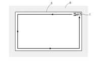
本発明の作業支援システムが適用される作業車の一例である普通型のコンバイン1について説明する。図1及び図2に示すように、コンバイン1の機体10は、機体フレーム9、収穫部H、クローラ式の走行装置11、運転部12、脱穀装置13、穀粒タンク14、搬送部16、穀粒排出装置18、衛星測位モジュール80、距離センサ81を備えている。We will now explain a
走行装置11は、コンバイン1の機体10における下部に備えられている。また、走行装置11は、エンジン(図示せず)からの動力によって駆動する。そして、コンバイン1は、走行装置11によって自走可能である。The
また、運転部12、脱穀装置13、穀粒タンク14は、走行装置11の上側に備えられている。また、運転部12、脱穀装置13、穀粒タンク14は、機体フレーム9に支持されている。運転部12には、コンバイン1を操作または監視するオペレータが搭乗可能である。なお、オペレータは、コンバイン1の機外からコンバイン1の作業を監視していても良い。The
図1及び図2に示すように、穀粒排出装置18は、穀粒タンク14の上側に設けられている。また、衛星測位モジュール80及び距離センサ81は、運転部12の上面に取り付けられている。なお、衛星測位モジュール80による衛星航法を補完するために、ジャイロ加速度センサや磁気方位センサを組み込んだ慣性航法ユニットが衛星測位モジュール80に組み込まれている。もちろん、慣性航法ユニットは、コンバイン1において衛星測位モジュール80と別の箇所に配置されても良い。As shown in Figures 1 and 2, the
収穫部Hは、機体10における前部に備えられている。収穫部Hは、刈取シリンダ15Aを介して機体フレーム9に対して昇降可能に構成されている。そして、搬送部16は、収穫部Hの後側に設けられている。また、収穫部Hは、刈取装置15及びリール17を含んでいる。The harvesting unit H is provided at the front of the
刈取装置15は、圃場5(図3及び図4参照)の植立穀稈を刈り取る。また、リール17は、機体左右方向に沿うリール軸芯17b周りに回転駆動しながら収穫対象の植立穀稈を掻き込む。刈取装置15により刈り取られた刈取穀稈は、搬送部16へ送られる。The
この構成により、収穫部Hは、圃場5の作物を収穫する。そして、コンバイン1は、刈取装置15によって圃場5の植立穀稈を刈り取りながら走行装置11によって走行する刈取走行が可能である。With this configuration, the harvesting section H harvests crops in the
収穫部Hにより収穫された刈取穀稈は、搬送部16によって機体後方へ搬送される。これにより、刈取穀稈は脱穀装置13へ搬送される。The harvested stalks harvested by the harvesting section H are transported to the rear of the machine by the
脱穀装置13において、刈取穀稈は脱穀処理される。脱穀処理により得られた穀粒は、穀粒タンク14に貯留される。穀粒タンク14に貯留された穀粒は、必要に応じて、穀粒排出装置18によって機外に排出される。The harvested stalks are threshed in the threshing
ここで、コンバイン1は、図3及び図4に示すように、外縁領域6の内側に位置する圃場5において、作物を収穫するように構成されている。なお、外縁領域6は、圃場5を囲む状態で設けられている。外縁領域6には、例えば、畦畔61、給排水ポンプ(不図示)、水口(不図示)等が含まれている。As shown in Figures 3 and 4, the
コンバイン1は、図3に示すように、圃場5の外周領域SA(図4参照)において作業走行を実行可能に構成されている。外周領域SAは本発明の『圃場の外周部』に相当する。外周領域SAにおけるコンバイン1の周回数は二回~三回である。なお、周回数は、二回以上のいかなる回数であっても良い。そして、コンバイン1は、外周領域SAにおいて作業走行を行った後、図4に示すように、外周領域SAよりも内側の作業対象領域CAにおいて作業走行を行う。As shown in FIG. 3, the
なお、本実施形態における「作業走行」は、具体的には、上述の刈取走行である。なお、「作業走行」は、走行しながら、植立穀稈の刈り取り以外の作業を行うものであっても良い。In this embodiment, the "working run" is specifically the above-mentioned reaping run. The "working run" may also be a run in which work other than reaping planted stalks is performed.
〔作業支援システムの構成について〕
図5~図16に基づいて本発明の作業支援システムの構成を説明する。図5に示すように、本発明の作業支援システムに、制御ユニット20とマップ生成ユニット30とが備えられている。コンバイン1には、多数のECUと呼ばれる電子制御ユニットが備えられている。制御ユニット20は電子制御ユニットの一構成であって、コンバイン1の各種入出力機器等と車載LANなどの配線網を通じて信号通信(データ通信)を可能に構成されている。つまり、制御ユニット20はコンバイン1に備えられている。マップ生成ユニット30は、コンバイン1に備えられず、例えば遠隔地に設けられた管理コンピュータに組み込まれたものであって、制御ユニット20と通信ネットワークを介してデータの送受信を可能に構成されている。なお、マップ生成ユニット30は、コンバイン1の電子制御ユニットの一構成であっても良い。[About the configuration of the work support system]
The configuration of the work support system of the present invention will be described with reference to Figs. 5 to 16. As shown in Fig. 5, the work support system of the present invention includes a
制御ユニット20に、位置情報取得部21、物体位置データ取得部22、形状記憶部23、及び、走行制御部24が備えられている。コンバイン1に距離センサ81が備えられている。The
距離センサ81は、例えば、ToF(Time of Flight)測定方式の測定装置である二次元スキャンLiDARであって、赤外線レーザー光のような空中伝搬する信号を検出信号として送信する。検出信号が検出対象物に照射されると、検出信号は検出対象物の表面で反射する。距離センサ81は、検出対象物の表面で反射した検出信号を、反射信号として取得する。そして、距離センサ81は、検出信号を送信してから反射信号を取得するまでの時間に基づいて、距離センサ81と検出対象物との距離を算出するように構成されている。このため、距離センサ81は、ToF測定方式の測定結果に基づいて前方領域FA(図1及び図2参照)に存在する物体の位置及び高さを検出可能である。距離センサ81の検出結果は、経時的に物体位置データ取得部22へ送られる。なお、距離センサ81は三次元スキャンLiDARであっても良い。また、距離センサ81の測定方式は、ToF測定方式に限定されず、ステレオマッチング測定方式等であっても良い。The
衛星測位モジュール80は、GPS(グローバル・ポジショニング・システム)で用いられる人工衛星GSからのGPS信号を受信する。そして、図5に示すように、衛星測位モジュール80は、受信したGPS信号に基づいて、コンバイン1の自車位置を示す測位データを位置情報取得部21へ送る。なお、衛星測位モジュール80は、GPSを利用するものでなくても良い。例えば、衛星測位モジュール80は、GPS以外のGNSS(GLONASS、Galileo、QZSS、BeiDou、等)を利用するものであっても良い。The
位置情報取得部21は、衛星測位モジュール80により出力された測位データに基づいて、コンバイン1の位置情報を経時的に取得する。The position
物体位置データ取得部22は、コンバイン1の圃場走行中にコンバイン1の進行方向前方において距離センサ81によって検出された物体の三次元位置データを経時的に取得する。物体位置データ取得部22は、外縁領域6(図1~図4参照)のうち、コンバイン1の進行方向前方における畦畔61(図1及び図2参照)や給排水ポンプ(不図示)、水口(不図示)等の三次元位置データを取得する。つまり、物体位置データ取得部22は、コンバイン1の圃場走行中に外縁領域6における物体の三次元位置データを経時的に取得する。The object position
また、本実施形態における物体位置データ取得部22は、外縁領域6だけでなく、圃場5の物体の三次元データも取得可能に構成されている。例えば、物体位置データ取得部22は、圃場5における植立穀稈や倒伏穀稈、雑草等の三次元データも取得可能である。In addition, the object position
なお、本発明に係る「圃場走行」は、圃場5において走行することを意味する。例えば、圃場5における最外周部分を走行することは、本発明に係る「圃場走行」の具体例である。また、圃場5における最外周部分よりも内側を走行することも、本発明に係る「圃場走行」の具体例である。In addition, "field travel" according to the present invention means travel in the
物体位置データ取得部22によって取得された三次元位置データは、経時的に記憶部31へ送られる。また、位置情報取得部21により算出されたコンバイン1の位置座標は、経時的に記憶部31へ送られる。The three-dimensional position data acquired by the object position
図5に示すマップ生成ユニット30に、記憶部31、データ判定部32、閾値設定部33、マスキング領域設定部34,マスキング部35、マップ生成部36、及び、障害物判定部37が備えられている。The
記憶部31は、走行軌跡記憶部31Aと、三次元位置データ記憶部31Bと、閾値記憶部31Cと、第一位置データ記憶部31Dと、マップ記憶部31Eと、を有する。The
走行軌跡記憶部31Aには、位置情報取得部21により算出されたコンバイン1の位置座標が時間情報と紐付けられて経時的に記憶される。このため、走行軌跡記憶部31Aにはコンバイン1の走行軌跡が記憶される。The travel
三次元位置データ記憶部31Bは、物体位置データ取得部22によって取得された三次元位置データを、取得したタイミングにおける時間情報と、取得したタイミングにおける位置情報と、取得したタイミングにおける慣性航法ユニット(不図示)の検出結果(例えばピッチ角、ロール角、ヨー角)と、に関連付けて記憶する。The three-dimensional position
なお、取得したタイミングにおける位置情報が、取得したタイミングにおける慣性航法ユニットの検出結果に基づいて補正される構成であっても良い。つまり、衛星測位モジュール80によって測位された位置情報はコンバイン1の傾斜分だけ誤差を生じるが、この位置情報の誤差が、慣性航法ユニットの検出結果に応じて補正可能である。三次元位置データ記憶部31Bには多数の三次元位置データが記憶されている。The position information at the acquired timing may be corrected based on the detection results of the inertial navigation unit at the acquired timing. In other words, the position information measured by the
図3及び図4に基づいて上述したように、コンバイン1は、圃場5の外周領域SAにおいて二回~三回の周回走行を行う。このため、周回走行の走行軌跡に沿った三次元位置データが三次元位置データ記憶部31Bに記憶されている。コンバイン1が外周領域SAにおいて二回~三回の周回走行を行うと、三次元位置データ記憶部31Bには、外縁領域6に関する三次元位置データが、二回~三回の周回走行の分だけ重複して記憶される。As described above with reference to Figures 3 and 4, the
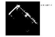
コンバイン1が外縁領域6に沿って圃場5を周回走行した際に取得された三次元位置データの集合体に基づいて、図7に示すような圃場5及び外縁領域6の高さ分布マップの構成が可能である。図7に示す高さ分布マップでは、白色の濃淡で高さが示され、白色が濃くなるほど高さが高くなる。Based on a collection of three-dimensional position data acquired when the
物体位置データ取得部22によって圃場一周分に相当する三次元位置データが取得されると、図7に示す高さ分布マップに基づいて、本発明の外縁マップが生成される。外縁マップは、図6のステップ#01~ステップ#10に示している手順に基づいて生成される。以下、外縁マップの生成手法を図5~図13に基づいて説明する。When the object position
図6のステップ#01において、データ判定部32は三次元位置データ記憶部31Bから三次元位置データの集合体を読み出す。そしてステップ#02において、データ判定部32は高さ閾値HTを閾値記憶部31Cから読み出す。高さ閾値HTは閾値設定部33によって設定され、閾値記憶部31Cに記憶される。In
図5に示す閾値設定部33は、物体位置データ取得部22によって取得された三次元位置データの高さ情報に関する高さ閾値HTを設定する。高さ閾値HTは、例えば、走行装置11の底部の高さや、機体フレーム9の下端部の対地高さや、収穫部Hが最も上昇した状態における収穫部Hの下端部の対地高さ等である。閾値記憶部31Cには、これら複数の異なる高さ閾値HTを記憶可能に構成されている。例えば閾値設定部33は、コンバイン1のオペレータが手入力で設定した値を受け付けて高さ閾値HTとして設定しても良いし、外部の管理コンピュータから通信ネットワークを介して送られてきたデータ値を受け付けて高さ閾値HTとして設定しても良い。つまり、高さ閾値HTは、コンバイン1における種々の部分の対地高さに応じて設定可能である。閾値記憶部31Cに一つ以上の高さ閾値HTが記憶され、データ判定部32が閾値記憶部31Cから高さ閾値HTを読み出す。The
本実施形態では、高さ閾値HTよりも高い高さ情報を有する三次元位置データを『第一位置データ』と称し、高さ閾値HTよりも低い高さ情報を有する三次元位置データを『第二位置データ』と称する。In this embodiment, three-dimensional position data having height information higher than the height threshold HT is referred to as "first position data," and three-dimensional position data having height information lower than the height threshold HT is referred to as "second position data."
図6に示すステップ#03において、データ判定部32は、三次元位置データを、高さ閾値HTを基準にして、第一位置データであるか第二位置データであるかを判定する判定処理を行う。本実施形態では、データ判定部32は、物体位置データ取得部22によって圃場一周分の三次元位置データが取得されてから、当該判定処理を行う。In
図6に示すステップ#04において、三次元位置データのうち、データ判定部32によって第一位置データであると判定された三次元位置データは、第一位置データ記憶部31Dへ送られる。そして、第一位置データ記憶部31Dは第一位置データに該当する三次元位置データの集合体を記憶する。In
第一位置データ記憶部31Dに記憶された第一位置データをプロットすると、図8に示すようなマップが生成される。図8に示すマップを『二値化マップ』と称する。つまり、第一位置データの集合体に基づいて二値化マップを生成すると、図7の高さ分布マップが、図8では高さ閾値HTを挟んで白黒に二値化されたマップとなる。図8では、三次元位置データのうち、第一位置データが白色で示され、第二位置データが黒色で示されている。このように、データ判定部32は、コンバイン1が外縁領域6に沿って圃場5を周回走行した際に取得された三次元位置データを用いて判定処理を行う。When the first position data stored in the first position
上述したように、高さ閾値HTは、コンバイン1における種々の部分の対地高さに応じて設定可能である。このため、例えば高さ閾値HTが、機体フレーム9の下端部の対地高さであれば、図8において白色で示している第一位置データの部分は、機体フレーム9が接触する可能性のある部分である。例えば高さ閾値HTが、収穫部Hが最も上昇した状態における収穫部Hの対地高さであれば、図8において白色で示している第一位置データの部分は、収穫部Hが最も上昇した場合であっても収穫部Hが接触する可能性のある部分である。As described above, the height threshold HT can be set according to the height of various parts of the
図8において白色で示している第一位置データのうち、圃場5に位置する第一位置データは、例えば高く伸びた植立穀稈から取得した三次元位置データに基づくものであることが考えられる。外縁領域6における第一位置データを適切に抽出するため、マスキング部35によるマスキング処理が行われる。Of the first position data shown in white in FIG. 8, the first position data located in the
マスキング部35がマスキング処理を適切に行うために、図6のステップ#05~ステップ#07で示すように、マスキング領域設定部34によってマスキング領域が設定される。図3及び図4に基づいて上述したように、コンバイン1は、圃場5の外周領域SAにおいて二回~三回の周回走行を行って、周回走行の走行軌跡は走行軌跡記憶部31Aに記憶されている。図6に示すステップ#05において、マスキング領域設定部34は、三次元位置データの取得中にコンバイン1が走行した走行軌跡のデータを、走行軌跡記憶部31Aから読み出す。In order for the
図6に示すステップ#06において、マスキング領域設定部34は、走行軌跡のうち、外縁領域6に最も近い要素の集合体である最外軌跡要素群の位置情報を抽出する。次に、図6に示すステップ#07において、マスキング領域設定部34は、当該最外軌跡要素群によって囲まれた領域をマスキング領域として設定するとともに、当該マスキング領域の位置情報を算定する。In
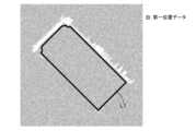
図9には、二つのマップが示されている。図9における左側のマップは、図8に基づいて上述した二値化マップである。図9における右側のマップは、当該マスキング領域の位置情報を示すマスキングマップである。図9のマスキングマップにおいて、黒色で示している領域がマスキング領域であって、最外軌跡要素群を含めて圃場5の領域がマスキング領域として設定されている。当該マスキングマップのデータは、マスキング領域設定部34からマスキング部35へ送られる。Two maps are shown in FIG. 9. The map on the left in FIG. 9 is the binarized map described above based on FIG. 8. The map on the right in FIG. 9 is a masking map showing the position information of the masking area. In the masking map in FIG. 9, the area shown in black is the masking area, and the area of the
図6に示すステップ#08において、マスキング部35は、マスキングマップを用いて二値化マップにおける第一位置データのマスキング処理を行う。具体的には、マスキング部35は、図9に示している二値化マップとマスキングマップとを重ね合わせ、二値化マップにおいて白色で示している第一位置データのうち、マスキング領域の範囲内に含まれる第一位置データを除去する。換言すると、図9に示している二値化マップとマスキングマップとの夫々において両方とも白色の部分の領域だけを第一位置データの領域として抽出する。これにより、二値化マップとマスキングマップとを重ね合わせた際に白色で重複する領域のみが残る。マスキング処理後の二値化マップは、マップ生成部36へ送られる。図10にはマスキング処理後の二値化マップを示しており、第一位置データが白色で示されている。In
マップ生成部36は、マスキング処理後の第一位置データの集合体に基づいて、圃場走行中のコンバイン1が越境不能な境界を示す外縁マップを生成する。図11には、マスキング処理後の二値化マップと、黒線の走行軌跡線L1と、を重ね合わせたものが示されている。走行軌跡線L1は、三次元位置データの取得中にコンバイン1が走行した走行軌跡のうちの最外周の走行軌跡である。走行軌跡線L1は、本発明の『最外軌跡要素群』に相当する。The
図6に示すステップ#09において、マップ生成部36は、図12に示すように、走行軌跡線L1に対して垂直方向に延出線L2を延ばす。延出線L2が延ばされる先に第一位置データが存在する場合には、延出線L2が第一位置データと接触する位置が延出線L2の延出先端点となる。また、延出線L2が延ばされる先に第一位置データが存在しない場合には、走行軌跡線L1から垂直方向に予め設定された距離だけ離間する位置が延出線L2の延出先端点となる。マップ生成部36は、走行軌跡線L1の全周に亘って延出線L2を延ばす処理を行う。In
延出線L2の夫々には、時計回りまたは反時計回りの方向において順番にインデックス値が割り当てられている。また、延出線L2の一つが隣の延出線L2と交差する場合には、その延出線L2はインデックス値にカウントされず、延出線L2の延出先端点がインデックス値の順番通りに並ぶように、延出線L2の夫々は構成されている。これにより、インデックス値を割り当てられた延出線L2の延出先端点が時計回りまたは反時計回りの方向に沿ってインデックス値の順番通りに並ぶ。Each extension line L2 is assigned an index value in order in a clockwise or counterclockwise direction. Furthermore, when one of the extension lines L2 intersects with an adjacent extension line L2, that extension line L2 is not counted in the index value, and each extension line L2 is configured so that the extension end points of the extension lines L2 are lined up in the order of the index values. As a result, the extension end points of the extension lines L2 to which index values are assigned are lined up in the order of the index values along the clockwise or counterclockwise direction.
マップ生成部36は、延出線L2の延出先端点をインデックス値の順番で繋ぎ、図13に示すような圃場5を囲む外縁線L3を生成する。外縁線L3は、圃場走行中のコンバイン1が越境不能な境界を示すものである。このように、マップ生成部36は、記憶部31によって記憶された第一位置データの集合体のうち、マスキング処理後の第一位置データの集合体を用いて、圃場走行中のコンバイン1が越境不能な境界を示す外縁マップを生成する。図6のステップ#10において、生成された外縁マップが、マップ生成部36からマップ記憶部31Eへ送られ、マップ記憶部31Eに記憶される。The
上述したように、閾値記憶部31Cには、複数の異なる高さ閾値HTを記憶可能に構成されている。このため、複数の異なる高さ閾値HTごとに、図6のステップ#01~ステップ#10(またはステップ#02~ステップ#10)の処理が行われて、複数の異なる高さ閾値HTの夫々に対応する外縁マップが生成される。つまり、データ判定部32は、複数の異なる高さ閾値HTを基準にした複数の判定処理が可能であり、マップ生成部36は、複数の判定処理ごとに外縁マップを生成する。As described above, the
図14に示す例では、走行装置11の底部と、機体フレーム9の下端部と、収穫部Hが最も上昇した状態における収穫部Hの下端部と、の夫々で高さ閾値HTが設定される。そして、図14に示す例では、三つの高さ閾値HTの夫々を基準としてデータ判定部32による判定処理が行われ、当該判定処理ごとの外縁マップが示されている。In the example shown in FIG. 14, height thresholds HT are set at the bottom of the traveling
図14において、機体フレーム9の下端部を基準に生成された外縁マップの外縁線L32が、走行装置11の底部を基準に生成された外縁マップの外縁線L31よりも圃場外側に位置する。この場合、機体フレーム9の下端部の対地高さが、畦畔61(図1及び図2参照)の高さよりも高いため、走行装置11が圃場5に位置する状態で、機体フレーム9が圃場5よりも外側の畦畔61にはみ出すことが可能となる。In FIG. 14, the outer edge line L32 of the outer edge map generated based on the lower end of the
また、図14において、収穫部Hが最も上昇した状態における収穫部Hの下端部を基準に生成された外縁マップの外縁線L33が、走行装置11の底部を基準に生成された外縁マップの外縁線L31よりも圃場外側に位置する。この場合、収穫部Hを最上昇位置まで上昇させれば、走行装置11が圃場5に位置する状態で、収穫部Hが圃場5よりも外側の畦畔61にはみ出すことが可能となる。In addition, in FIG. 14, the outer edge line L33 of the outer edge map generated based on the lower end of the harvesting part H when the harvesting part H is in its most raised state is located outside the field more than the outer edge line L31 of the outer edge map generated based on the bottom of the traveling
コンバイン1に形状記憶部23と走行制御部24とが備えられている。形状記憶部23にコンバイン1の主要な部位の形状情報が記憶されている。主要な部位の形状情報とは、例えば三次元座標に基づく形状であったり、主要な部位の高さ情報であったり、走行装置11に対する主要な部位のオーバーハングの長さであったりする。The
走行制御部24は、外縁マップと、コンバイン1の位置情報と、主要な部位の形状情報と、に基づいてコンバイン1の走行を制御する。また、走行制御部24は、刈取シリンダ15Aを制御可能に構成されている。走行制御部24が刈取シリンダ15Aを伸び方向に制御すると、搬送部16及び収穫部Hは、一体的に、収穫部Hが上昇する方向に揺動する。また、走行装置11にはモンロー機構が備えられ、走行制御部24がモンロー機構を上昇させる制御を行うと、機体フレーム9の高さが上昇する。つまり、走行制御部24は、コンバイン1の主要な部位が、その主要な部位の高さに対応する高さ閾値HTを基準として生成された外縁マップの外縁線L3を越境しないように、コンバイン1の走行を制御する。図7に示す高さ分布マップから直接的に越境判定が行われる構成であれば、微小区画毎の高さの比較処理を行う必要があるが、本発明の外縁マップが越境判定に用いられることによって、越境判定の処理の高速化が実現される。The
〔一時的な障害物の存在を判定する手法について〕
上述したように、コンバイン1が外周領域SAにおいて二回~三回の周回走行を行うと、三次元位置データ記憶部31Bには、外縁領域6に関する三次元位置データが、二回~三回の周回走行の分だけ重複して記憶される。本実施形態では、マップ生成ユニット30に障害物判定部37が備えられている。障害物判定部37は、例えば異なる周回数において取得した複数の三次元位置データに基づいて、当該三次元位置データに一時的な障害物が含まれるか否かを判定可能に構成されている。[Method of determining the presence of temporary obstacles]
As described above, when the
障害物判定部37が判定処理を行う場合、データ判定部32は、異なる周回数において取得された二周分以上の三次元位置データを三次元位置データ記憶部31Bから読み出す。そしてデータ判定部32は、同一値の高さ閾値HTを基準として二周分以上の三次元位置データに対して上述の判定処理を行い、二周分以上の第一位置データを第一位置データ記憶部31Dに記憶する。そして、夫々の第一位置データの集合体に対して上述のマスキング処理が行われる。このため、障害物判定部37が判定処理を行う場合、図6におけるステップ#01~ステップ#08が二度以上繰り返される。ステップ#01~ステップ#08の繰り返し回数は、例えば外周領域SAにおける周回数に応じて決定されても良い。このときの繰り返し処理において、ステップ#02では同一値の高さ閾値HTが読み出される。When the
図15及び図16に、二値化マップと外縁マップとを重ね合わせたマップを示している。図15では、一周目に取得された三次元位置データに基づくマップを示し、図16では、二周目に取得された三次元位置データに基づくマップを示している。一周目のマップにおける第一位置データの分布と、二周目のマップにおける第一位置データの分布と、が同一であれば、障害物判定部37は第一位置データに一時的な障害物が含まれていないと判定する。Figures 15 and 16 show maps in which the binarized map and the outer edge map are superimposed. Figure 15 shows a map based on three-dimensional position data acquired in the first lap, and Figure 16 shows a map based on three-dimensional position data acquired in the second lap. If the distribution of the first position data in the map for the first lap is the same as the distribution of the first position data in the map for the second lap, the
図15では、一周目のマップにおける第一位置データの領域に領域Gが存在するが、二周目のマップにおける第一位置データの領域に領域Gが存在しない。領域Gは、例えば他の農作業機や運搬トラック、作業者等であることが考えられる。障害物判定部37は、一周目のマップにおける第一位置データのうち、領域Gにおける第一位置データを一時的な障害物と判定する。そして、図6におけるステップ#09及びステップ#10の処理は、領域Gの存在しない二周目のマップに基づいて行われる。In FIG. 15, area G exists in the area of the first position data in the map of the first loop, but area G does not exist in the area of the first position data in the map of the second loop. Area G could be, for example, another agricultural machine, a transport truck, a worker, etc. The
つまり、障害物判定部37は、一周目のマップと二周目のマップとを比較して、一周目のマップと二周目のマップとの一方のみに存在する第一位置データの領域を検出する。そして障害物判定部37は、一周目のマップと二周目のマップとの一方のみに存在する第一位置データの領域を、一時的な障害物の存在領域であると判定する。換言すると、障害物判定部37は、外縁領域6において第一位置データの集合体を示す複数のマップを重ね合わせ、何れのマップにも第一位置データの存在する領域のみを残すマスキング処理を行う。In other words, the
図16の二周目のマップに示される外縁線L3は、図15の一周目のマップに示される外縁線L3と比較して、領域Gに対応する箇所において圃場外側に位置する。このように、障害物判定部37の判定処理によって、第一位置データから一時的な障害物が除去され、外縁マップの精度が向上する。The outer edge line L3 shown in the second loop map in FIG. 16 is located outside the field at a location corresponding to area G, compared to the outer edge line L3 shown in the first loop map in FIG. 15. In this way, the determination process of the
〔別実施形態〕
本発明は、上述の実施形態に例示された構成に限定されるものではなく、以下、本発明の代表的な別実施形態を例示する。[Another embodiment]
The present invention is not limited to the configurations exemplified in the above-described embodiments, and other representative embodiments of the present invention will be described below.
(1)走行制御部24は、自動走行を可能な構成であっても良いし、手動走行をアシストする構成であっても良い。走行制御部24が手動走行をアシストする構成である場合、コンバイン1に例示される作業車の一部が外縁線L3を越境しそうになると、作業車が自動的に停車する構成であっても良い。(1) The driving
(2)上述の実施形態では、コンバイン1が外縁領域6に沿って圃場5を周回走行した際に三次元位置データが取得されるが、この実施形態に限定されない。例えば、コンバイン1が圃場5において180度の旋回走行を伴う往復走行を繰り返しながら、物体位置データ取得部22が外縁領域6から三次元位置データを取得する構成であっても良い。つまり、データ判定部32は、物体位置データ取得部22によって圃場5の一周分に相当する三次元位置データが取得されてから、判定処理を行う構成であっても良い。(2) In the above embodiment, the three-dimensional position data is acquired when the
(3)上述の実施形態では、データ判定部32は、物体位置データ取得部22によって圃場5の一周分に相当する三次元位置データが取得されてから、第一位置データであるか第二位置データであるかの判定処理を行うが、この実施形態に限定されない。例えば、物体位置データ取得部22によって新たな三次元位置データが取得され、三次元位置データ記憶部31Bに新たな三次元位置データが一つ一つ記憶される度に、データ判定部32が当該判定処理を行う構成であっても良い。換言すると、高さ閾値HTが変更されるごとに、データ判定部32は、同一の三次元位置データの集合体に対して判定処理を行い、かつ、マップ生成部36は外縁マップを生成する構成であっても良い。(3) In the above embodiment, the
(4)図5に示す位置情報取得部21と物体位置データ取得部22との少なくとも一方は、制御ユニット20ではなくマップ生成ユニット30に設けられても良い。(4) At least one of the position
(5)上述の実施形態では、マスキング領域設定部34は、図9に示すマスキング領域に、作業車の走行軌跡の最外軌跡要素群を含めるが、最外軌跡要素群を含めない構成であっても良い。(5) In the above embodiment, the masking
(6)位置情報取得部21と衛星測位モジュール80とが、本発明の位置情報取得部として一体的に構成されても良い。(6) The location
(7)物体位置データ取得部22と距離センサ81とが、本発明の物体位置データ取得部として一体的に構成されても良い。(7) The object position
(8)図14では、外縁線L33が、収穫部Hが最も上昇した状態における収穫部Hの下端部の対地高さに基づいて生成されているが、この実施形態に限定されない。例えば、高さ閾値HTが、収穫部Hの所定の対地高さとして設定され、外縁線L33が、当該所定の高さに上昇した状態における収穫部Hの対地高さに基づいて生成されても良い。(8) In FIG. 14, the outer edge line L33 is generated based on the height from the ground of the lower end of the harvesting part H when the harvesting part H is in the most elevated state, but this is not limited to this embodiment. For example, the height threshold HT may be set as a predetermined height from the ground of the harvesting part H, and the outer edge line L33 may be generated based on the height from the ground of the harvesting part H when it is elevated to the predetermined height.
(9)上述の実施形態では、作業車としてコンバイン1が例示されたが、作業車は、作業機が装着されたトラクタ、田植機、管理機等であっても良い。(9) In the above embodiment, a
なお、上述の実施形態(別実施形態を含む、以下同じ)で開示される構成は、矛盾が生じない限り、他の実施形態で開示される構成と組み合わせて適用することが可能である。また、本明細書において開示された実施形態は例示であって、本発明の実施形態はこれに限定されず、本発明の目的を逸脱しない範囲内で適宜改変することが可能である。The configurations disclosed in the above-mentioned embodiments (including other embodiments, the same applies below) can be applied in combination with configurations disclosed in other embodiments, so long as no contradiction occurs. Furthermore, the embodiments disclosed in this specification are merely examples, and the present invention is not limited to these embodiments, and can be modified as appropriate within the scope of the purpose of the present invention.
本発明は、圃場を走行しながら作業を行う作業車のための作業支援システムに適用できる。The present invention can be applied to a work assistance system for a work vehicle that performs work while traveling in a field.
1 :コンバイン(作業車)
5 :圃場
6 :外縁領域
21 :位置情報取得部
22 :物体位置データ取得部
23 :形状記憶部
24 :走行制御部
31 :記憶部
32 :データ判定部
33 :閾値設定部
34 :マスキング領域設定部
35 :マスキング部
36 :マップ生成部
HT :高さ閾値(閾値)
L1 :走行軌跡線(最外軌跡要素群)
L3 :外縁線(作業車が越境不能な境界)
SA :外周領域(圃場の外周部) 1: Combine (work vehicle)
5: Field 6: Outer edge area 21: Position information acquisition unit 22: Object position data acquisition unit 23: Shape memory unit 24: Travel control unit 31: Memory unit 32: Data determination unit 33: Threshold value setting unit 34: Masking area setting unit 35: Masking unit 36: Map generation unit HT: Height threshold (threshold value)
L1: Travel trajectory line (outermost trajectory element group)
L3: Outer boundary (the boundary where work vehicles cannot cross)
SA: Outer area (outer periphery of the field)
Claims (8)
Translated fromJapanese前記作業車に設けられ、前記作業車が前記圃場を走行している最中に前記圃場の外縁領域に位置する物体の三次元位置データを経時的に取得する物体位置データ取得部と、
前記三次元位置データを、高さに関する閾値を基準にして、前記閾値よりも高い高さ情報を有する第一位置データであるか、前記閾値よりも低い高さ情報を有する第二位置データであるかを判定する判定処理を行うデータ判定部と、
前記三次元位置データのうち、前記データ判定部によって前記第一位置データであると判定されたデータを記憶する記憶部と、
前記記憶部によって記憶された前記第一位置データの集合体に基づいて、圃場走行中の前記作業車が越境不能な境界を示す外縁マップを生成するマップ生成部と、
前記作業車の位置情報を経時的に取得する位置情報取得部と、
前記三次元位置データの取得中に前記作業車が走行した走行軌跡のうち、前記圃場の外周部に最も近い要素の集合体である最外軌跡要素群の位置情報を抽出し、前記最外軌跡要素群によって囲まれた領域をマスキング領域として設定するとともに、前記マスキング領域の位置情報を算定するマスキング領域設定部と、
前記マスキング領域の範囲内に含まれる前記第一位置データを除去するマスキング処理を行うマスキング部と、が備えられ、
前記マップ生成部は、前記マスキング処理後の前記第一位置データの集合体を用いて前記外縁マップを生成する作業支援システム。 A work assistance system for a work vehicle that performs work while traveling in a field,
an object position data acquisition unit provided in the work vehicle and configured to acquire three-dimensional position data of objects located in an outer edge region of the field over time while the work vehicle is traveling in the field;
a data determination unit that performs a determination process to determine whether the three-dimensional position data is first position data having height information higher than a threshold value related to height, or second position data having height information lower than the threshold value, based on the height threshold value;
a storage unit that stores data determined by the data determination unit to be the first position data among the three-dimensional position data;
a map generating unit that generates an outer edge map indicating a boundary that the work vehicle traveling in a farm field cannot cross based on the collection of the first position data stored in the memory unit;
a location information acquisition unit that acquires location information of the work vehicle over time;
a masking area setting unit that extracts position information of an outermost trajectory element group, which is a collection of elements that are closest to an outer periphery of the farm field, from among the travel trajectory traveled by the work vehicle while acquiring the three-dimensional position data, sets an area surrounded by the outermost trajectory element group as a masking area, and calculates the position information of the masking area;
a masking unit that performs a masking process to remove the first position data included within the range of the masking area,
The map generation unit generates the outer edge map using a collection of the first position data after the masking process.
前記マップ生成部は、前記複数の判定処理ごとに、前記外縁マップを生成する請求項1または2に記載の作業支援システム。 The data determination unit is capable of performing a plurality of determination processes based on a plurality of different threshold values;
The work support system according to claim1 , wherein the map generating unit generates the outer edge map for each of the plurality of determination processes.
前記閾値が変更されるごとに、前記データ判定部は、同一の前記三次元位置データの集合体に対して前記判定処理を行い、かつ、前記マップ生成部は、前記外縁マップを生成する請求項1または2に記載の作業支援システム。 A threshold setting unit capable of changing the threshold is provided,
The work support system according to claim 1or 2, wherein each time the threshold is changed, the data determination unit performs the determination process on the same collectionof three-dimensional position data , and the map generation unit generates the outer edge map.
前記外縁マップと前記作業車の位置情報と前記形状情報とに基づいて、前記作業車の走行を制御する走行制御部と、が備えられている請求項1から7の何れか一項に記載の作業支援システム。 A shape memory unit in which shape information of the work vehicle is stored;
The work support system according to any one of claims 1 to7 , further comprising a driving control unit that controls driving of the work vehicle based on the outer boundary map, position information of the work vehicle, and the shape information.
Priority Applications (3)
| Application Number | Priority Date | Filing Date | Title |
|---|---|---|---|
| JP2021106828AJP7630377B2 (en) | 2021-06-28 | 2021-06-28 | Work Support System |
| KR1020220068011AKR20230001512A (en) | 2021-06-28 | 2022-06-03 | Work support system |
| CN202210705779.1ACN115599086A (en) | 2021-06-28 | 2022-06-21 | Work support system |
Applications Claiming Priority (1)
| Application Number | Priority Date | Filing Date | Title |
|---|---|---|---|
| JP2021106828AJP7630377B2 (en) | 2021-06-28 | 2021-06-28 | Work Support System |
Publications (2)
| Publication Number | Publication Date |
|---|---|
| JP2023005113A JP2023005113A (en) | 2023-01-18 |
| JP7630377B2true JP7630377B2 (en) | 2025-02-17 |
Family
ID=84841912
Family Applications (1)
| Application Number | Title | Priority Date | Filing Date |
|---|---|---|---|
| JP2021106828AActiveJP7630377B2 (en) | 2021-06-28 | 2021-06-28 | Work Support System |
Country Status (3)
| Country | Link |
|---|---|
| JP (1) | JP7630377B2 (en) |
| KR (1) | KR20230001512A (en) |
| CN (1) | CN115599086A (en) |
Citations (6)
| Publication number | Priority date | Publication date | Assignee | Title |
|---|---|---|---|---|
| JP2014056506A (en) | 2012-09-13 | 2014-03-27 | Toyota Central R&D Labs Inc | Obstacle detection device, and moving body with the same |
| JP2019169059A (en) | 2018-03-26 | 2019-10-03 | ヤンマー株式会社 | Travel area shape specification device |
| JP2019191743A (en) | 2018-04-20 | 2019-10-31 | 株式会社小松製作所 | Work machine control system, work machine, and work machine control method |
| JP2020095566A (en) | 2018-12-14 | 2020-06-18 | ヤンマーパワーテクノロジー株式会社 | Travel route generation device |
| JP2020178659A (en) | 2019-04-26 | 2020-11-05 | 国立大学法人京都大学 | Harvester |
| JP2021007313A (en) | 2019-06-28 | 2021-01-28 | 株式会社クボタ | Harvester |
Family Cites Families (1)
| Publication number | Priority date | Publication date | Assignee | Title |
|---|---|---|---|---|
| JP7068961B2 (en) | 2018-08-06 | 2022-05-17 | 株式会社クボタ | External shape calculation system and external shape calculation method |
- 2021
- 2021-06-28JPJP2021106828Apatent/JP7630377B2/enactiveActive
- 2022
- 2022-06-03KRKR1020220068011Apatent/KR20230001512A/enactivePending
- 2022-06-21CNCN202210705779.1Apatent/CN115599086A/enactivePending
Patent Citations (6)
| Publication number | Priority date | Publication date | Assignee | Title |
|---|---|---|---|---|
| JP2014056506A (en) | 2012-09-13 | 2014-03-27 | Toyota Central R&D Labs Inc | Obstacle detection device, and moving body with the same |
| JP2019169059A (en) | 2018-03-26 | 2019-10-03 | ヤンマー株式会社 | Travel area shape specification device |
| JP2019191743A (en) | 2018-04-20 | 2019-10-31 | 株式会社小松製作所 | Work machine control system, work machine, and work machine control method |
| JP2020095566A (en) | 2018-12-14 | 2020-06-18 | ヤンマーパワーテクノロジー株式会社 | Travel route generation device |
| JP2020178659A (en) | 2019-04-26 | 2020-11-05 | 国立大学法人京都大学 | Harvester |
| JP2021007313A (en) | 2019-06-28 | 2021-01-28 | 株式会社クボタ | Harvester |
Also Published As
| Publication number | Publication date |
|---|---|
| JP2023005113A (en) | 2023-01-18 |
| KR20230001512A (en) | 2023-01-04 |
| CN115599086A (en) | 2023-01-13 |
Similar Documents
| Publication | Publication Date | Title |
|---|---|---|
| EP3841859B1 (en) | Harvester, surrounding condition detection system, surrounding condition detection program, recording medium recording the surrounding condition detection program and surrounding condition detection method | |
| CN112585424A (en) | Outline shape calculation system, outline shape calculation method, outline shape calculation program, recording medium containing outline shape calculation program, field map creation system, field map creation program, recording medium containing field map creation program, and field map creation method | |
| JP7381402B2 (en) | automatic driving system | |
| JP7527838B2 (en) | Agricultural machinery | |
| WO2020218464A1 (en) | Harvester, obstacle determination program, recording medium on which obstacle determination program is recorded, obstacle determination method, agricultural work machine, control program, recording medium on which control program is recorded, and control method | |
| WO2019103089A1 (en) | Harvesting machine, travel distance limit calculation program, recording medium having travel distance limit calculation program recorded thereon, travel distance limit calculation method, agricultural work vehicle, turning control program, recording medium having turning control program recorded thereon, turning control method, combine control system, combine control program, recording medium having combine control program recorded thereon, and combine control method | |
| JP7466276B2 (en) | Work vehicle coordination system | |
| JP7482838B2 (en) | Work Support System | |
| JP7630377B2 (en) | Work Support System | |
| JP7546470B2 (en) | Agricultural machinery | |
| JP7423443B2 (en) | harvester | |
| JP7630421B2 (en) | Driving Management System | |
| JP7558119B2 (en) | Work Support System | |
| JP7724755B2 (en) | Route management system | |
| JP2021185842A (en) | Travel route management system | |
| JP7664863B2 (en) | Cruise control system | |
| JP7641763B2 (en) | Route management system | |
| JP7641889B2 (en) | system | |
| JP7515436B2 (en) | Route Generation System | |
| JP7738540B2 (en) | System and work vehicle | |
| JP7641764B2 (en) | Harvesting Machine | |
| CN119136659A (en) | Aircraft control system | |
| JP2024084935A (en) | Work vehicle and automatic driving control system for work vehicle | |
| JP2024076610A (en) | Work vehicle | |
| JP2024084486A (en) | Work vehicle |
Legal Events
| Date | Code | Title | Description |
|---|---|---|---|
| A621 | Written request for application examination | Free format text:JAPANESE INTERMEDIATE CODE: A621 Effective date:20230623 | |
| A977 | Report on retrieval | Free format text:JAPANESE INTERMEDIATE CODE: A971007 Effective date:20240215 | |
| A131 | Notification of reasons for refusal | Free format text:JAPANESE INTERMEDIATE CODE: A131 Effective date:20240402 | |
| A521 | Request for written amendment filed | Free format text:JAPANESE INTERMEDIATE CODE: A523 Effective date:20240529 | |
| A02 | Decision of refusal | Free format text:JAPANESE INTERMEDIATE CODE: A02 Effective date:20240820 | |
| A521 | Request for written amendment filed | Free format text:JAPANESE INTERMEDIATE CODE: A523 Effective date:20241115 | |
| A911 | Transfer to examiner for re-examination before appeal (zenchi) | Free format text:JAPANESE INTERMEDIATE CODE: A911 Effective date:20241125 | |
| TRDD | Decision of grant or rejection written | ||
| A01 | Written decision to grant a patent or to grant a registration (utility model) | Free format text:JAPANESE INTERMEDIATE CODE: A01 Effective date:20250107 | |
| A61 | First payment of annual fees (during grant procedure) | Free format text:JAPANESE INTERMEDIATE CODE: A61 Effective date:20250204 | |
| R150 | Certificate of patent or registration of utility model | Ref document number:7630377 Country of ref document:JP Free format text:JAPANESE INTERMEDIATE CODE: R150 |