JP7628945B2 - Method and apparatus for selecting a position for reading an image on a slide medium - Patents.com - Google Patents
Method and apparatus for selecting a position for reading an image on a slide medium - Patents.comDownload PDFInfo
- Publication number
- JP7628945B2 JP7628945B2JP2021500096AJP2021500096AJP7628945B2JP 7628945 B2JP7628945 B2JP 7628945B2JP 2021500096 AJP2021500096 AJP 2021500096AJP 2021500096 AJP2021500096 AJP 2021500096AJP 7628945 B2JP7628945 B2JP 7628945B2
- Authority
- JP
- Japan
- Prior art keywords
- image
- control unit
- fluid sample
- data points
- reaction cell
- Prior art date
- Legal status (The legal status is an assumption and is not a legal conclusion. Google has not performed a legal analysis and makes no representation as to the accuracy of the status listed.)
- Active
Links
Images


Classifications
- G—PHYSICS
- G06—COMPUTING OR CALCULATING; COUNTING
- G06T—IMAGE DATA PROCESSING OR GENERATION, IN GENERAL
- G06T7/00—Image analysis
- G06T7/70—Determining position or orientation of objects or cameras
- G06T7/73—Determining position or orientation of objects or cameras using feature-based methods
- G—PHYSICS
- G06—COMPUTING OR CALCULATING; COUNTING
- G06T—IMAGE DATA PROCESSING OR GENERATION, IN GENERAL
- G06T7/00—Image analysis
- G06T7/70—Determining position or orientation of objects or cameras
- G06T7/73—Determining position or orientation of objects or cameras using feature-based methods
- G06T7/74—Determining position or orientation of objects or cameras using feature-based methods involving reference images or patches
- G—PHYSICS
- G06—COMPUTING OR CALCULATING; COUNTING
- G06T—IMAGE DATA PROCESSING OR GENERATION, IN GENERAL
- G06T2207/00—Indexing scheme for image analysis or image enhancement
- G06T2207/10—Image acquisition modality
- G06T2207/10056—Microscopic image
- G—PHYSICS
- G06—COMPUTING OR CALCULATING; COUNTING
- G06T—IMAGE DATA PROCESSING OR GENERATION, IN GENERAL
- G06T2207/00—Indexing scheme for image analysis or image enhancement
- G06T2207/30—Subject of image; Context of image processing
- G06T2207/30004—Biomedical image processing
Landscapes
- Engineering & Computer Science (AREA)
- Computer Vision & Pattern Recognition (AREA)
- Physics & Mathematics (AREA)
- General Physics & Mathematics (AREA)
- Theoretical Computer Science (AREA)
- Investigating Or Analysing Materials By Optical Means (AREA)
- Investigating Or Analysing Biological Materials (AREA)
- Automatic Analysis And Handling Materials Therefor (AREA)
- Image Analysis (AREA)
- Apparatus Associated With Microorganisms And Enzymes (AREA)
Description
Translated fromJapanese本発明は、標的位置を使用してアッセイを実施可能とするために、乾燥スライド又は他の多孔性/固体媒体のような反応セル上の標的位置の位置決めをする方法および装置に、一般に関連し、より具体的には、固体媒体上における、標的位置として流体サンプルの読み取り中心を位置決めする方法及び装置に関する。The present invention relates generally to methods and apparatus for positioning a target location on a reaction cell, such as a dry slide or other porous/solid medium, so that an assay can be performed using the target location, and more specifically to methods and apparatus for positioning the reading center of a fluid sample as a target location on a solid medium.
アッセイを実施する1つの方法は、固体又は多孔質媒体上に吐出された流体サンプルの画像を使用することである。しかしながら、この方法の問題は、軸対象の勾配が、流体サンプルが吐出された位置の中心から放射状に広がり、画像プロファイルが平坦とならないことがある点である。この問題は、例えば、計量、媒体の位置又は変化のある媒体における不正確性により、意図しない位置でサンプルを吐出することによって起きる可能性がある。アッセイを実施するための領域が予め定められた位置である場合、実施されるアッセイの正確性を減じる大きな変動がある可能性がある。別の問題は、光学的欠陥(例えば、埃、コーティングの欠陥等)又は、アッセイの信号を劣化させる可能性がある意図しない流れのパターンによる反応画像に欠陥がある可能性があることである。 One method of performing an assay is to use an image of a fluid sampledispensed onto a solid or porous medium. However, a problem with this method is that axially symmetric gradients may radiate from the center of the location where the fluid sample wasdispensed , resulting in a non-flat image profile. This problem may occur, for example, bydispensing the sample at an unintended location due to inaccuracies in metering, media location, or varying media. If the area for performing the assay is at a predefined location, there may be large variations that reduce the accuracy ofthe assay performed. Another problem is that there may be defects in the reaction image due to optical defects (e.g., dust, coating defects, etc.) or unintended flow patterns that may degrade the assay signal.
本開示は、例えば、アッセイ信号の標的位置を中心とした所定の領域における平均光学強度を得ることによって、ドライスライド又は他の固体媒体のような反応セル中の標的位置を決める、及び標的位置を使用してアッセイを実施するための方法及び装置を目的とする。本明細書に開示の任意の他の実施形態と共に使用することができる例示的な実施形態において、少なくとも1つのアッセイを実施する方法は、反応セル上に位置する流体サンプルの少なくとも1つの画像を得るステップと、少なくとも1つの画像に基づいて複数微分データ点を含む微分データのセットを生成するステップと、それぞれの複数の微分データ点のための画像勾配データ点を決定するステップと、画像勾配データ点に基づいて反応セル内の流体サンプルの標的位置を決定するステップと、反応セル内の流体サンプルの標的位置を使用して少なくとも1つのアッセイを実施するステップと、を含む。The present disclosure is directed to methods and apparatus for determining a target location in a reaction cell, such as a dry slide or other solid medium, for example, by obtaining an average optical intensity in a predetermined area centered on a target location of an assay signal, and performing an assay using the target location. In an exemplary embodiment that can be used with any other embodiment disclosed herein, a method of performing at least one assay includes obtaining at least one image of a fluid sample located on a reaction cell, generating a set of differential data including multiple differential data points based on the at least one image, determining an image gradient data point for each of the multiple differential data points, determining a target location of the fluid sample in the reaction cell based on the image gradient data points, and performing at least one assay using the target location of the fluid sample in the reaction cell.
本明細書に開示の任意の他の実施形態と共に使用することができる別の実施形態において、反応セルは、固体媒体、乾燥スライド、又は反応キュベットを含む。In another embodiment, which can be used with any other embodiment disclosed herein, the reaction cell comprises a solid medium, a dry slide, or a reaction cuvette.
本明細書に開示の任意の他の実施形態と共に使用することができる別の実施形態において、標的位置は、前記反応セル内の前記流体サンプルの均一領域のほぼ中心である。In another embodiment, which can be used with any other embodiment disclosed herein, the target location is approximately the center of a uniform region of the fluid sample within the reaction cell.
本明細書に開示の任意の他の実施形態と共に使用することができる別の実施形態において、本方法は、複数の画像からの標的位置を使用して、複数のアッセイを実施することを含む。In another embodiment, which can be used with any other embodiment disclosed herein, the method includes performing multiple assays using target locations from multiple images.
本明細書に開示の任意の他の実施形態と共に使用することができる別の実施形態において、微分データ点は、少なくとも1つの画像における色に基づく一次微分である。実施形態において、少なくとも1つの画像における色は、光強度を表す。In another embodiment, which can be used with any other embodiment disclosed herein, the derivative data points are first derivatives based on color in at least one image. In an embodiment, the color in at least one image represents light intensity.
本明細書に開示の任意の他の実施形態と共に使用することができる別の実施形態において、流体サンプルの前記標的位置を決定するステップは、(i)第2の画像勾配点よりも低い画像勾配を有する第1の画像勾配データ点を使用すること、又は、(ii)第1の画像勾配データ点よりも高い画像勾配を有する第2の画像勾配データ点を除外すること、の少なくとも1つを含む。実施形態において、これは、一次微分値が画像全体にわたって取られ、次に、閾値よりも高い一次微分値を有する全ての画素が除去され、その結果、残りの画素の中心が標的位置を見つけるために使用することができることを意味する。In another embodiment, which can be used with any other embodiment disclosed herein, determining the target location of the fluid sample includes at least one of: (i) using a first image gradient data point that has a lower image gradient than a second image gradient point; or (ii) excluding a second image gradient data point that has a higher image gradient than the first image gradient data point. In an embodiment, this means that a first derivative is taken across the entire image, and then all pixels that have a first derivative value higher than a threshold are removed, so that the centers of the remaining pixels can be used to find the target location.
本明細書に開示の任意の他の実施形態と共に使用することができる別の実施形態において、本方法は、少なくとも1つの画像から画像の欠陥を除去するステップを含む。In another embodiment, which may be used with any other embodiment disclosed herein, the method includes removing image defects from at least one image.
本明細書に開示の任意の他の実施形態と共に使用することができる別の実施形態において、少なくとも1つの画像は2次元画像である。In another embodiment, which may be used with any other embodiment disclosed herein, at least one image is a two-dimensional image.
本明細書に開示の任意の他の実施形態と共に使用することができる別の実施形態において、流体サンプルの標的位置を決定するステップは、流体サンプルと結合する少なくとも1つの試薬から形成された、反応セル内の指示薬分子の指示薬反応を検出すること又は測定することを含む。In another embodiment, which can be used with any other embodiment disclosed herein, determining the target location of the fluid sample includes detecting or measuring an indicator reaction of an indicator molecule in the reaction cell formed from at least one reagent that binds to the fluid sample.
本明細書に開示の任意の他の実施形態と共に使用することができる別の実施形態において、本方法は、標的位置周辺の読み取り領域を形成するステップを含み、少なくとも1つのアッセイを実施するステップは、読み取り領域を使用することを含む。In another embodiment, which can be used with any other embodiment disclosed herein, the method includes forming a read area around the target location, and performing at least one assay includes using the read area.
本明細書に開示の任意の他の実施形態と共に使用することができる一般的な実施形態において、少なくとも1つのアッセイを実施する方法は、反応セル上に位置する流体サンプルの少なくとも1つの画像を得るステップと、少なくとも1つの画像に基づいて複数の微分データ点を含む微分データセットを作成するステップと、複数の微分データ点に基づいて流体サンプルの標的位置を決定するステップと、標的位置の周囲に読み取り領域を形成するステップと、読み取り領域を用いて少なくとも1つのアッセイを実施するステップとを含む。In a general embodiment that can be used with any other embodiment disclosed herein, a method of performing at least one assay includes obtaining at least one image of a fluid sample located on a reaction cell, creating a differential data set including a plurality of differential data points based on the at least one image, determining a target location of the fluid sample based on the plurality of differential data points, forming a read area around the target location, and performing at least one assay using the read area.
本明細書に開示の任意の他の実施形態と共に使用することができる別の実施形態において、反応セルは、固体媒体、乾燥スライド、又は反応キュベットを含む。In another embodiment, which can be used with any other embodiment disclosed herein, the reaction cell comprises a solid medium, a dry slide, or a reaction cuvette.
本明細書に開示の任意の他の実施形態と共に使用することができる別の実施形態において、読み取り領域は、少なくとも1つの画像で、ほぼ円形を示す。In another embodiment, which may be used with any other embodiment disclosed herein, the reading area exhibits a substantially circular shape in at least one image.
本明細書に開示の任意の他の実施形態と共に使用することができる別の実施形態において、読み取り領域は、少なくとも1つの画像で、ほぼ楕円形を示す。In another embodiment, which may be used with any other embodiment disclosed herein, the reading area exhibits an approximately oval shape in at least one image.
本明細書に開示の任意の他の実施形態と共に使用することができる別の実施形態において、本方法は、それぞれの複数の微分データ点のための画像勾配データ点を決定するステップ、及び、画像勾配データ点に基づいて流体サンプルの標的位置を決定するステップ、を含む。In another embodiment, which may be used with any other embodiment disclosed herein, the method includes determining an image gradient data point for each of the plurality of differential data points, and determining a target location for the fluid sample based on the image gradient data points.
本明細書に開示の任意の他の実施形態と共に使用することができる別の実施形態において、本方法は、複数のイメージに由来する標的位置を使用して、複数のアッセイを実施することを含む。In another embodiment, which can be used with any other embodiment disclosed herein, the method includes performing multiple assays using target locations from multiple images.
本明細書に開示の任意の他の実施形態と共に使用することができる別の実施形態において、少なくとも1つの画像は、2次元画像である。In another embodiment, which can be used with any other embodiment disclosed herein, at least one image is a two-dimensional image.
本明細書に開示の任意の他の実施形態と共に使用することができる一般的な実施形態において、少なくとも1つのアッセイを実施するための装置は、流体サンプルが位置された少なくとも1つの反応セルを受容するように構成されたスライド受容位置と、反応セル内に位置する流体サンプルの少なくとも1つの画像を得るために、スライド受容位置に対して位置され及び配置される画像装置と、(i)前記少なくとも1つの画像からの微分データ点を分析することで、前記反応セル内に位置する前記流体サンプル内の標的位置を決定する、及び(ii)標的位置に基づいて少なくとも1つのアッセイを実施するように構成された制御ユニットと備える。In a general embodiment that can be used with any other embodiment disclosed herein, an apparatus for performing at least one assay comprises a slide receiving position configured to receive at least one reaction cell in which a fluid sample is located, an imaging device positioned and arranged relative to the slide receiving position to obtain at least one image of the fluid sample located in the reaction cell, and a control unit configured to (i) determine a target location within the fluid sample located in the reaction cell by analyzing differential data points from the at least one image, and (ii) perform at least one assay based on the target location.
本明細書に開示の任意の他の実施形態と共に使用することができる別の実施形態において、反応セルは、固体媒体、乾燥スライド、又は反応キュベットを含む。In another embodiment, which can be used with any other embodiment disclosed herein, the reaction cell comprises a solid medium, a dry slide, or a reaction cuvette.
本明細書に開示の任意の他の実施形態と共に使用することができる別の実施形態において、固体媒体は、第2の反応セルを含む。In another embodiment, which can be used with any other embodiment disclosed herein, the solid medium comprises a second reaction cell.
本明細書に開示の任意の他の実施形態と共に使用することができる別の実施形態において、標的位置は、反応セル内の前記流体サンプルの均一領域のほぼ中心位置である。In another embodiment, which can be used with any other embodiment disclosed herein, the target location is approximately the center location of the uniform region of the fluid sample within the reaction cell.
本明細書に開示の任意の他の実施形態と共に使用することができる別の実施形態において、制御ユニットは、それぞれの複数の微分データ点のための画像勾配データ点を分析することで、標的位置を決定するように構成される。In another embodiment, which may be used with any other embodiment disclosed herein, the control unit is configured to determine the target location by analyzing the image gradient data points for each of the plurality of differential data points.
本明細書に開示の任意の他の実施形態と共に使用することができる別の実施形態において、制御ユニットは、(i)第2の画像勾配データ点よりも低い画像勾配を有する第1の画像勾配データ点を使用する、又は、(ii)第1の画像勾配データ点よりも高い画像勾配を有する第2の画像勾配データ点を除外する、の少なくとも1つによって、前記標的位置を決定するように、構成されている。実施形態において、これは、1次微分値が画像全体にわたって取られ、次に、閾値よりも高い1次微分値を有する全ての画素が除去され、その結果、残りの画素の中心が標的位置を見つけるために使用されてもよいことを意味する。In another embodiment, which may be used with any other embodiment disclosed herein, the control unit is configured to determine the target location by at least one of: (i) using a first image gradient data point that has a lower image gradient than a second image gradient data point; or (ii) excluding a second image gradient data point that has a higher image gradient than the first image gradient data point. In an embodiment, this means that a first derivative is taken across the entire image, and then all pixels that have a first derivative value higher than a threshold are removed, so that the centers of the remaining pixels may be used to find the target location.
本明細書に開示の任意の他の実施形態と共に使用することができる別の実施形態において、制御ユニットは、第2の画像勾配データ点よりも低い画像勾配を有する第1の画像勾配データ点のほぼ幾何学的中心で標的位置を決定するように、構成される。In another embodiment, which may be used with any other embodiment disclosed herein, the control unit is configured to determine a target location at approximately the geometric center of a first image gradient data point that has a lower image gradient than a second image gradient data point.
本明細書に開示の任意の他の実施形態と共に使用することができる別の実施形態において、制御ユニットは、複数の画像からの標的位置を使用して、複数の異なるアッセイを実施するように構成されている。In another embodiment, which may be used with any other embodiment disclosed herein, the control unit is configured to perform multiple different assays using target locations from multiple images.
本明細書に開示の任意の他の実施形態と共に使用することができる別の実施形態において、反応セル内の流体サンプルの標的位置は、反応セル内で流体サンプル中の標的分子が試薬と反応するにつれて指示薬が表示のため発現するように指示薬反応が起こる位置に対応する。In another embodiment, which can be used with any other embodiment disclosed herein, the target location of the fluid sample in the reaction cell corresponds to a location where an indicator reaction occurs such that an indicator is expressed for indication as target molecules in the fluid sample react with a reagent in the reaction cell.
本明細書に開示される任意の他の実施形態と共に使用することができる別の実施形態において、図1~37と関連して開示される任意の構造及び機能と、図1~37と関連して開示される任意の他の構造及び機能と組み合わせることができる。In another embodiment that may be used with any other embodiment disclosed herein, any of the structures and features disclosed in association with FIGS. 1-37 may be combined with any other structure and features disclosed in association with FIGS. 1-37.
従って、本開示及び上記の態様に照らし、乾燥スライド、反応キュベット又は他の固体媒体の反応セルにおける標的位置を決めるための改善された方法および装置を提供することは、本開示の利点である。Thus, in light of the present disclosure and the above aspects, it is an advantage of the present disclosure to provide improved methods and apparatus for determining target positions in a dry slide, reaction cuvette, or other solid media reaction cell.
本明細書で議論される利点は、1つ又はいくつか、及びおそらく全てではない本明細書で開示されている実施形態で見出すことができる。付加的な特徴及び利点は、本明細書で説明されており、以下の詳細な説明と図面とから明らかになるであろう。The advantages discussed herein may be found in one or some, and possibly not all, of the embodiments disclosed herein. Additional features and advantages are described herein and will be apparent from the following detailed description and drawings.
ここで、本開示の実施形態は、添付の図面を参照するだけで、例として更に詳細に説明される。Embodiments of the present disclosure will now be described in further detail, by way of example only, with reference to the accompanying drawings, in which:
本開示は、反応セル上の標的位置を決め、標的位置を使用してアッセイを実施するための方法及び装置に関する。以下の詳細に説明するように、例えば、計算時間を改善する点と、中心外での計測の感度を低減する点と、エッジ/フレームを回避し、非アッセイ信号の影響を最小化する点と、画像の欠陥(例えば、埃、コーティング欠陥、ウィッキング等)を検出する及び取り除き、バイアスや外れ値を減少させる点とで、本開示の方法及び装置は有利である。画像の欠陥は、異物粒子、気泡、ひっかき傷等も含みうる。本開示は、反応セルを乾燥スライド、反応キュベット又は固体媒体として説明するが、当業者は、例えば、ニトロセルロースのような多孔質媒体、オクタロニープレートのような半多孔質及び固体媒体、キュベット、フローセル又は反応管のような液体試薬装置、及び/又は光学測定ゾーンを備えるラテラルフローアレイが埋め込まれた固体媒体チップのような、他の種類の反応セルで本開示を使用可能であることを理解するだろう。The present disclosure relates to methods and apparatus for determining target locations on a reaction cell and performing an assay using the target locations. As described in detail below, the disclosed methods and apparatus are advantageous, for example, in improving computation time, reducing sensitivity of off-center measurements, avoiding edges/frames and minimizing the effects of non-assay signals, and detecting and removing image defects (e.g., dust, coating defects, wicking, etc.) and reducing bias and outliers. Image defects may also include foreign particles, air bubbles, scratches, etc. Although the present disclosure describes the reaction cell as a dry slide, reaction cuvette, or solid media, those skilled in the art will understand that the present disclosure can be used with other types of reaction cells, such as, for example, porous media such as nitrocellulose, semi-porous and solid media such as Ouchterlony plates, liquid reagent devices such as cuvettes, flow cells, or reaction tubes, and/or solid media chips embedded with lateral flow arrays with optical measurement zones.
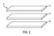
図1及び2は、本開示に従って使用可能な反応セルの例示的な実施形態を説明する。図1及び2において、反応セルは、本開示に係るアッセイシステム20で使用可能な固体媒体10である。固体媒体10は、例えば、単層又は複層薄膜素子であることができ、流体サンプルがその上に吐出される。図示の実施形態では、固体媒体10は、第1の層12を含む複数の層を含み、第1の層は、開口を備え、該開口を通って液体サンプルを受容する上部ベース層を提供するように構成された上側スライド載置層であることができる。第1の層は、流体サンプルをその上に広げるように構成されてもよい。固体媒体10は、特定のアッセイのために流体サンプルと反応するように構成された試薬を含む試薬層であり得る第2の層14も含む。第2の層14は、試薬層への支持又は剛性を提供する支持層も含むことができる。固体媒体は、光学分析に使用される低波長カットオフフィルタを提供するフィルタ層であり得る第3の層16も、更に含む。第3の層16は、光学分析のために、それを通る開口を備える、下部ベース層を提供するように構成される下部スライド載置層を含むことができる。1 and 2 illustrate an exemplary embodiment of a reaction cell that can be used in accordance with the present disclosure. In FIGS. 1 and 2, the reaction cell is a solid medium 10 that can be used in an
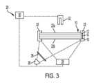
図3は、固体媒体10上の流体サンプルの画像内の標的位置を決め、標的位置を使用して1つ以上のアッセイを実施するために構成されたアッセイシステム20の例示的な実施形態を示す。図示のように、アッセイシステム20は、少なくとも1つの固体媒体10を受容するように構成されたスライド受容位置22と、固体媒体10上にサンプル流体を吐出するように構成されたサンプル吐出機構32と、固体媒体10上に位置する流体サンプルの少なくとも1つの画像を得るために固体媒体受容位置22に対応して位置決め及び配置された画像化装置24と、光を固体媒体10上に投射することで、光が固体媒体10上に吐出された液体サンプルによって変調され得るように構成された光源26(例えば、1つ以上の発光ダイオードライト)と、任意に、光源26からの光を、実施されているアッセイに固有の特定の波長に変調するように構成された光学フィルタ28と、を含むことができる。3 illustrates an exemplary embodiment of an
図示の実施形態において、スライド受容位置22は、流体サンプルが固体媒体10に加えられている間及び/又は固体媒体10は光源26によって照射され、画像化装置24によって画像化される間、固体媒体10を受容及び保持するように構成されている。図示の実施形態において、スライド受容位置22は、第1の開口22aと第2の開口22bとを作成する少なくとも1つのブラケットを含む。流体サンプルは、スライド受容位置22の第1の開口22aで(例えば、第1の層12の開口を通って)、固体媒体10に加えられることができ、一方、流体サンプルが試薬と反応した後、スライド受容位置22の第2の開口22bにより、固体媒体10が(例えば、第3の層16の開口を通じて)照射され画像化されることができる。スライド受容位置22によって固体異媒体10が受け取られる前に、流体サンプルの追加が起きることもあり、スライド受容位置22の下部にある第2の開口22bと対向するように、スライド受容位置22の上部にある第1の開口22aでは、固体媒体10の照射及び画像化が起きうることが更に理解されるべきである。In the illustrated embodiment, the
図2のアッセイシステム20は、制御ユニット30を更に含んでもよく、制御ユニットは、1つ以上のアッセイシステム20の構成要素を制御する、固体媒体10上の流体サンプルの標的位置を決定する、及び本明細書に記載の方法に従って、固体媒体10上の流体サンプルを分析するように構成されている。制御ユニット30は、プロセッサと、本明細書に記載の方法を実施するための命令を記憶する非一時的メモリとを含んでもよく、プロセッサは、1つ以上のアッセイを実施するため、アッセイシステム20の1つ以上の構成要素の制御するための命令を実行する。The
図4は、本開示の例示的な実施形態に係るサンプル吐出機構32によって固体媒体10上に吐出されている流体サンプルを示す。実施形態において、固体媒体10が、アッセイシステム20のスライド受容位置22に挿入される前に、流体サンプルは、ユーザによって手動で制御されたサンプル吐出機構32を介して固体媒体10上に吐出されうる。サンプル吐出機構32は、例えば、ピペット又は当技術分野で既知の他の流体吐出機構であることができる。代わりに、アッセイシステム20が、図3に示すように、サンプル吐出機構32を含むこともできる。ここで、サンプル吐出機構32は、ユーザによって又は制御ユニット30によって制御され、固体媒体10がアッセイシステム20のスライド受容位置22に挿入される前又は後に、流体サンプルを固体媒体10上に(又は中に)吐出してもよい。4 shows a fluid sample being ejected onto the
図4は、時間t1からt5にわたって、固体媒体10上に流体サンプルを吐出するサンプル吐出機構32を示す。この時間の間に、滞留及び横方向の流れは、固体媒体10中のコーティングされた材料の濃度のために空間的な勾配を作り出す。図示されているように、時間t1で、流体サンプルは、サンプル吐出機構32から固体媒体10上に排出され、固体媒体10と最初に接触する。時間t2で、流体サンプルは、サンプル吐出機構32から固体媒体10上に排出され続け、滞留領域44の形成が始まる。時間t3で、流体サンプルは、サンプル吐出機構32から固体媒体10上に排出され続け、固体媒体10全体に広がり、滞留領域44のサイズが増加する。時間t4で、サンプル吐出機構32は、流体サンプルの排出を停止し始め、サンプル吐出機構32と固体媒体10との間に流体ネッキングを生じさせ、それにより、サンプル吐出機構32のすぐ下の滞留領域44に集中させる。時間t5で、サンプル吐出機構32は、もはや流体サンプルを排出しておらず、滞留領域44を残している。図示の実施形態では、滞留領域44は、変動が最も少ない領域に対応する。いくつかの実施形態では、滞留領域44は、比較的低い光学密度変動性を有する及び/又は指示薬(例えば、サンプル色素)が比較的多く存在する。 4 shows the
図5は、図4の吐出プロセスにより生成された滞留領域44による、流体サンプルによって固体媒体10上に形成された液体レンズ46を示す。図示するように、流体サンプルは、固体媒体10上に円形の液体レンズ46を形成する。図5に示すように、サンプル吐出機構32からの軸対象の流体の流れにより円形の液体レンズ46は形成され、該流れは、固体媒体10のコーティングされた材料上で軸対象な分布をもたらす。Figure 5 shows a liquid lens 46 formed by the fluid sample on the
図6は、滞留領域44にわたる液体レンズ46の分布の例示的な実施形態を示す上面斜視図及び底面図を示す。図6の下側のプロットは、画像内の全てのピクセルにわたる2次元空間(つまり、x及びy空間)における光強度を示す。液体レンズ46の中心はより低い光強度を有し、一方、液体レンズ46の縁はより高い光強度を有する。図6のグラフ70は、グラフ72と同じ情報を有するが、光強度を表すためにz軸を備える3次元形式で表示されており、x軸及びy軸は、ピクセル位置を表す。ピクセル(x座標及びy座標)の光強度が高い場合、グラフ70と72のz値は大きくなる。光強度は「ADカウント」(「ADC」)と呼ばれる値で測定される。明るいピクセルは、暗いピクセルよりも大きなADカウント値を有する。6 shows a top perspective view and a bottom view illustrating an example embodiment of the distribution of liquid lenses 46 across the retention region 44. The bottom plot of FIG. 6 shows the light intensity in two-dimensional space (i.e., x and y space) across all pixels in the image. The center of the liquid lens 46 has a lower light intensity, while the edge of the liquid lens 46 has a higher light intensity.
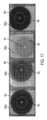
アッセイの動力学と、固体媒体10のコーティングされた材料の均一性と、の違いにより、固体媒体10上の流体サンプルから撮られた画像に形成され得る異なるパターンがある。図7A~7Cは、形成され得る3つの例示的なパターンを示す。図7Aは凹状パターンを示す。図7Bは凸状パターンを示し、図7Cは、複雑なパターンを示す。図7A~7Cの全ての3つのパターンは、中心の滞留領域44の共通の特徴と、局所的な非均一性によって乱されたZ軸対称放射と、を共有する。本開示は、この共通の特徴を使用して、1つ以上のアッセイを実施する際に使用するための標的位置として、固体媒体上の流体サンプルの均一領域(例えば、比較的均一な光強度)の中心を位置決めする。Due to differences in assay kinetics and uniformity of the coated material of the
図8は、画像を取得し、本明細書に開示されるように画像を処理することによって、少なくとも1つのアッセイを実施するための方法100を示す。実施形態において、制御ユニット30は、プロセッサ及び方法100のステップを実行するための命令を記憶する非一時的メモリを含み得る。プロセッサは、命令を実行して、アッセイシステム20の構成要素に図8のステップを実行させる。図8に示すステップのうちの1つ以上は、本開示の精神および範囲から逸脱することなく、省略することができ、及び/又は追加のステップを加えることができ、及び/又は特定のステップの順序を再配置することができることが、当業者によって理解されるべきである。Figure 8 illustrates a method 100 for performing at least one assay by acquiring images and processing the images as disclosed herein. In an embodiment, the
ステップ102で、画像化装置24は、固体媒体10上に吐出された流体サンプルの少なくとも1つの画像を記録する。例えば、光源26が固体媒体10に光を投射している間に、画像を記録することができる。光源26からの光は、固体媒体10上の1つ以上の試薬と反応したサンプル中の標的分子によって発光光を透過させて、反応の視覚的表示(例えば、指示薬反応)を提供するように構成される。いくつかの例では、光学フィルタ28及び/又は固体媒体10によって提供されるフィルタは、光源28からの光を変調するように構成される。画像化装置24は、例えば、電荷結合デバイス(「CCD」)カメラであることができ、これは、例えば、固体媒体10上にほぼ楕円形又は円形の流体サンプルを示す2次元画像を記録することができる。実施形態において、特定のアッセイに必要な波長は、制御ユニット30にプログラムされる又は提供されることができ、制御ユニット30は、光源26及び光学フィルタ28を制御して、画像が画像化装置24によって記録されている間に、実施されているアッセイのための正しい波長の光が、固体媒体10に投射されるようにすることができる。At step 102, the
ステップ104で、制御ユニット30は、画像を正規化し、アッセイの標的位置を決定する。ステップ104は、図9に示され、より詳細に説明されており、対応する説明は以下である。以下でより詳細に説明するように、ステップ104は、画像に基づいて複数の微分データ点を含む微分データのセットを1回以上作成し、複数の微分データ点のそれぞれのための画像勾配データ点を決定し、画像勾配データ点に基づいて固体媒体上の流体サンプルの標的位置を決定し、画像から画像の欠陥を除去する。In step 104, the
ステップ106では、制御ユニット30は、例えば、標的位置及び/又は標的位置の周囲の指定された領域における、光強度又は他の値を検出することによって、ステップ104で決定された標的位置を使用する。実施形態において、標的位置を中心点として使用して、標的位置の周りの指定された領域を形成することができる。例えば、標的位置を使用して、固体媒体10上に投射された光からの信号を検出するために使用される読み取り領域を作成することができる。2018年7月2日に出願された「縮小された読み取りウィンドウを使用するドライスライドアッセイ」と題する米国仮出願第62/693,120号は、標的位置の周囲に読み取り領域を作成するための方法を更に説明しており、この文献を参照により本明細書に組み込み、依拠する。他の実施形態では、標的位置を使用して、例えば、機器計測システム及び/又は光学系を位置合わせし、維持間隔を予測し、及び/又は反応セル干渉によるスペクトル誤差を最小化することができる。In
ステップ108で、制御ユニット30は、例えば、標的位置で、及び/又は標的位置から作成された読み取り領域内で、固体媒体10に投射された光からの画像信号の平均光強度を算出する。実施形態において、平均光強度は、読み取り領域内のADカウント値の合計を読み取り領域の総面積(総ピクセル数)の合計で割ったものである。In step 108, the
ステップ110で、制御ユニット30は、標的位置を使用して応答を算出する。エンドポイントアッセイ(例えば、UREA)について、応答を、同じスライド又は固体媒体10の異なる2つの読み取り間の信号差によって計算することができる。レートアッセイ(例えば、AST)について、応答を、同じ単一のスライド又は固体媒体10の複数の読み取りからの信号の経時変化の比率から算出することができる。スライド又は固体媒体10の位置は、インキュベーターの回転により時間とともにわずかに変化する可能性があるため、時間の経過とともに同じスライド媒体10上の各画像の標的位置を見つけることが望ましい。In step 110, the
ステップ112で、制御ユニット30は、例えば、応答を濃度に関連付ける較正曲線を使用して、流体サンプルの濃度を計算することによって、アッセイの実施を終了する。検量線は、既知の濃度の流体とその濃度に対応して得られる応答とを使用する較正プロセスで得ることができる。検量線では、濃度は応答の既知の関数である。実施形態において、制御ユニット30は、複数の画像からの標的位置を使用して、複数の異なるアッセイを実施することができる。At step 112, the
図9A及び9Bは、方法100のステップ104をより詳細に示す方法200を示す。
具体的に、図9A及び9Bは、標的位置を検出するため(図9A)、及び画像の欠陥(例えば、画像欠陥を修正する、又はエラーを報告する)を処理するため(図9B)に特別に設計されたアルゴリズムを示し、アッセイの正確性を改善する、及びアッセイのバイアス及び外れ値を減少させる。以下でより詳細に説明するように、標的位置を検出する際に(図9A)、アッセイ固有のステップサイズでの画像の一次微分を使用して、画像勾配を取得する。次に、閾値を適用して、高勾配領域を削除する。最後に、画像の残りのピクセルの中心が標的位置として使用される。 9A and 9B show a
Specifically, Figures 9A and 9B show algorithms specifically designed to detect target locations (Figure 9A) and to handle image defects (e.g., correct image defects or report errors) (Figure 9B) to improve assay accuracy and reduce assay bias and outliers. As described in more detail below, in detecting target locations (Figure 9A), the first derivative of the image at an assay-specific step size is used to obtain the image gradient. Then, a threshold is applied to remove high gradient regions. Finally, the center of the remaining pixels of the image is used as the target location.
標的位置(例えば、最小の変動及び最大の信号を有する均一な領域の中心)を見つけた後、標的位置と同期位置との間の距離をチェックする、標的位置と関連するスパイクの数を検出する、及び標的位置の軸対称性とノイズレベルとを分析することによって、画質を調べることができる(図9B)。チェックされた量の1つ以上でアッセイ固有の閾値を超える場合、画像に対してエラーコードが発行され、該エラーコードは、分析された流体サンプルは信頼できないと判断される可能性があるため、方法100を新しい流体サンプルで再開する必要があることを示す。エラーが見つからない場合、標的位置での画像の平均光学強度を上記のように算出することができる。いくつかの実施形態において、スパイクの数が閾値を下回る場合、方法200は、画像からスパイクを除去するように構成され、それによりアッセイシステムの再現性を改善する。しかし、スパイクの数が閾値を超える場合、画像は破棄される又は、エラーコート及び/又はアラートに関連付けられる。After finding the target location (e.g., the center of a homogeneous region with minimal variation and maximum signal), the image quality can be checked by checking the distance between the target location and the synchronization location, detecting the number of spikes associated with the target location, and analyzing the axial symmetry and noise level of the target location (FIG. 9B). If an assay-specific threshold is exceeded in one or more of the checked quantities, an error code is issued for the image, indicating that the analyzed fluid sample may be deemed unreliable and that the method 100 should be restarted with a new fluid sample. If no error is found, the average optical intensity of the image at the target location can be calculated as described above. In some embodiments, if the number of spikes is below the threshold, the
本開示の精神および範囲から逸脱することなく、図9A及び9Bに示す1つ以上のステップを省略する、及び/又は追加のステップを追加することができる、及び/又は特定のステップの順序を再配置することができることが当業者によって理解されるべきである。方法100と同様に、制御ユニット30は、プロセッサと、図9A及び9Bの方法のステップを実行するための命令を格納する非一時的なメモリと、を含み得ることが理解されるべきである。プロセッサは、命令を実行して、アッセイシステム20の構成要素に開示されたステップを実行させる。It should be understood by one of ordinary skill in the art that one or more steps shown in FIGS. 9A and 9B may be omitted, and/or additional steps may be added, and/or the order of certain steps may be rearranged without departing from the spirit and scope of the present disclosure. It should be understood that, similar to method 100,
ステップ200は、図8のステップ102で画像化デバイス22によって記録された画像から始まる。ステップ200で、制御ユニット30は、例えば、アッセイタイプ、流体サンプルのデフォルトの中心40、流体サンプルについて検出されたパターンのタイプ(例えば、凹状、凸状、複雑)等に関連するメタデータに画像を関連付けることによって画像を分析する。メタデータに格納されたパラメータは、事前にプログラムされ、制御ユニット30のメモリ内に格納されることができ、又は特定のアッセイのためにユーザによって入力されることができる。流体サンプルのデフォルト中心40は、例えば、固体媒体10の中心、又は流体サンプルの中心があると予想される吐出位置の中心であり得る。Step 200 begins with an image recorded by
流体サンプルについて検出されたパターンのタイプは、例えば、固体媒体10中の可溶性材料の再分布に対する感度、分析物/試薬濃度、及び/又は化学の動力学に応じて、平坦又は非平坦(例えば、凹状、凸状、又はより複雑な形状)であり得る。図10は、固体媒体10上に吐出された流体によって形成された異なる例示的なパターンを示し、一方、図11は、異なるアッセイのための元の画像及び一次空間微分を示す図を示す。図10及び11は、滞留領域44により小さな値があることを示す。図示のように、流体サンプルは、例えば、非常に小さな勾配を有する滞留領域44(例えば、ピーク又は谷強度)、より大きな勾配を有する洗い流し領域、及び/又は大きな勾配のあるエッジ(乾湿界面又はスライドフレームから)を有し得る。2018年7月2日に出願された「縮小された読み取りウィンドウを使用したドライスライドアッセイ」と題された米国仮出願第62/693,120号は、洗い流し領域がどのように画像に影響を及ぼし、大きな勾配を引き起こし得るかを更に説明し、その説明は引用によって本明細書に組み込まれ、依拠される。本方法によれば、適切な閾値が適用されると、すべての大きな勾配領域を除去することができ、滞留領域44を識別することができる。The type of pattern detected for the fluid sample may be planar or non-planar (e.g., concave, convex, or more complex shapes) depending on, for example, the sensitivity to redistribution of soluble materials in the
ステップ202で、制御ユニット30は、画像がまだこの形状になっていない場合、画像をフラットフィールド画像に変換することによって画像を正規化する。実施形態において、画像を正規化することは、エラーを低減するために、読み取り領域全体に適用される光エネルギーを正規化することを含む。実施形態において、正規化は2つのステップを有する。最初のステップは、生の信号からダークリード信号を差し引くことを含む。ダークリード信号は、光源がオフになっているCCDセンサからのデジタル信号である。この計算により、バックグラウンドのデジタルノイズが最小化される。第2のステップは、信号にフラットフィールド関数を乗算することにより、フラットフィールド信号を使用して暗補正信号を正規化することである。フラットフィールド関数は、均一で平らな白色及び/又は反射面である標準面を読み取ることによって取得される。フラットフィールド関数は、標準面の面全体で「1」の値を生成する関数である場合がある。測定された光強度分布がf=f(x,y)であると仮定すると、フラットフィールドはF=1/fである。In step 202, the
ステップ204で、制御ユニット30は、例えば、画像トリミングサイズ、ステップサイズ、閾値パラメータ等のアッセイ固有のパラメータを決定または受け入れる。アッセイ固有のパラメータは、事前にプログラムされ、制御ユニット30のメモリ内に格納されることができ、又は特定のアッセイのためにユーザが入力することができる。画像トリミングサイズは、例えば、ステップ206でトリミングされる画像に意図されるサイズであることができ、入力される、又は制御ユニット30によって自動生成されることができる。例示的な実施形態では、画像トリミングサイズは、中心点周りの直径(たとえば、デフォルトの中心40)が約4.5mmであることができる。ステップサイズと閾値パラメータも同様に入力される、又はプロセスの後のステップで使用される所定の値である。各アッセイは、独自のトリミングサイズ、ステップサイズ、及び閾値を有する(例えば、URICトリミングサイズ=3.64mm、ステップサイズ0.28mm、及び閾値=10)。In step 204, the
ステップ206で、制御ユニット30は、画像の領域46を切り出す。例では、制御ユニット30は、固体媒体10上の流体サンプルのデフォルト中心40の予想される位置に基づいて領域46をトリミングする。実施形態において、デフォルト中心40は、例えば、固体媒体10の中心として、又は流体サンプルの中心が予想される吐出位置の中心としてステップ200から知られている。したがって、画像は、例えば、ステップ204で決定された画像トリミングサイズに基づくデフォルトの中心40を囲む円(例えば、直径4.5ミリメートル(「mm」)を有する円)としてトリミングすることができる。別の実施形態において、画像は、特定のサイズに制限されることなく、検出された光強度に基づいてトリミングすることができる。2018年7月2日に出願された、「縮小読み取りウィンドウを使用したドライスライドアッセイ」と題された米国仮出願第62/693,120号は、画像の領域を切り取って読み取り領域を作成する方法を更に説明しており、その説明は、引用により本明細書に取り込まれ、依拠される。In step 206, the
ステップ208において、制御ユニット30は、トリミングされた画像のデフォルトの中心40を記録する。実施形態において、デフォルトの中心40は、ステップ102から既知であり、画像は、デフォルトの中心40に基づいてトリミングされる。別の実施形態では、デフォルトの中心40は、トリミングされた画像の中心に対応せず、新しくトリミングされた画像に基づいて決定され得る。例えば、画像は、ステップ206で光強度に基づいてトリミングされることができ、次いで、デフォルトの中心40は、トリミングされた画像の幾何学的中心として記録されることができる。In step 208, the
ステップ210~214で、制御ユニット30は、トリミングされた画像に基づいて、複数の微分データ点を含む微分データのセットを作成する。実施形態において、微分データ点は、画像内の色に基づく一次微分であることができ、それぞれが、二値画像を定義する画像勾配データ点を含み得る。実施形態において、少なくとも1つの画像の色は、光強度を表す。実施形態において、一次微分は、空間における画像光強度を示すものである。例えば、画像内の各ピクセルには、ADカウント(つまり、ADC)で測定された固有の光強度を有する。一次微分は、事前に定義された距離でのピクセル間の光強度の差を、ピクセル間の距離で割ったものであり得る。In steps 210-214, the
ステップ210で、制御ユニット30は、ステップ204で決定されたアッセイ固有のステップサイズで、トリミングされた画像の一次微分(例えば、傾き)の絶対値を取得することによって、微分データのセットを作成する。一次微分は、トリミングされた画像内のアッセイ固有のステップサイズを使用して、中心差分法を使用して計算できる。例えば、微分データのセットは、以下の式:
Slope1=max(|du/dx|,|du/dy|)
を使用して決定できる。ここで、uは画像内のピクセルでの光強度(ADカウント値)である。x及びyは、そのピクセルの座標位置である。傾きはx方向とy方向との両方に沿って計算でき、最大絶対値は傾きとして定義できる。微分を計算するためのステップサイズは、アッセイ固有である。以下でより詳細に説明するように、スロープ1(Slope1)が閾値よりも小さい場合、その質量の値は「1」であり、それ以外の場合、その質量の値は「0」である。 In step 210, the
Slope1 =max(|du/dx|,|du/dy|)
where u is the light intensity (AD count value) at a pixel in the image; x and y are the coordinate location of the pixel; the slope can be calculated along both the x and y directions, and the maximum absolute value can be defined as the slope. The stepsize for calculating the derivative is assay specific. As explained in more detail below, if Slope1 is less than a threshold, then the value of the mass is "1"; otherwise, the value of the mass is "0".
ステップ212及び214で、制御ユニット30は、微分データのセットの複数の微分データ点のそれぞれについて画像勾配データ点を決定し、それにより二値画像を生成する。実施形態において、ステップ212で、ステップ210で決定されたスロープ1がアッセイ固有の閾値よりも大きい場合、制御ユニット30は、画像勾配データ点をゼロ(0)に設定する。つまり、より勾配の高いピクセルはゼロ(0)に設定され、二値画像からスパイク、エッジ等を削除する。次に、ステップ214で、制御ユニット30は、画像勾配データ点がゼロ(0)の値より大きい場合、画像勾配データ点を1の値に等しく設定する。つまり、スロープ1が閾値を超える場合、各ピクセル位置での画像勾配データ点(例えば、二値画像内の位置での質量)は、ゼロ(0)であり、スロープ1が閾値を下回る場合は1である。実施形態において、第2の画像勾配データ点よりも低い画像勾配を有する第1の画像勾配データ点が含まれるか、1に設定され、及び/又は(ii)第1の画像勾配データ点より高い画像勾配を有する第2の画像勾配データ点は除外される、又はゼロ(0)に設定される。 At steps 212 and 214, the
ステップ216で、制御ユニット30は、画像勾配データ点に基づいて(例えば、楕円形または円形の)流体サンプルの標的位置を決定する。例えば、標的位置は、二値画像(例えば、図9Aに示される二値画像)の重心として計算され得る。実施形態において、中心位置は、以下の式:
を使用して取得することができる。式において、質量mijは、その位置インデックスiとjとの関数である。座標値xijとyijとも、位置インデックスiとjとの関数である。質量は、全てのインデックスにわたって閾値内にあるかどうかに応じて、「1」又は「0」の値と等しい。中心Xc座標は、すべてのインデックスにわたる質量と対応するx座標との積を合計し、その積の合計を総質量で除算して算出される。同様に、中心Yc座標は、すべてのインデックスにわたる質量と対応するy座標との積を合計し、その積の合計を総質量で除算することにより算出される。 At step 216, the
In the formula, mass mij is a function of its location index i and j. Coordinate values xij and yij are also functions of location index i and j. Mass is equal to a value of "1" or "0" depending on whether it is within the threshold across all indices. The center Xc coordinate is calculated by summing the products of mass and corresponding x coordinates across all indices and dividing the sum of the products by the total mass. Similarly, the center Yc coordinate is calculated by summing the products of mass and corresponding y coordinates across all indices and dividing the sum of the products by the total mass.
次に、二値画像の重心は、固体媒体10上の流体サンプルの均質領域のほぼ幾何学的中心である、固体媒体10上の流体サンプルの標的位置として指定され得る。The centroid of the binary image can then be designated as a target location of the fluid sample on the
図9Bのステップ218~252において、制御ユニット30は、画像からの欠陥(例えば、画像の不完全性、塵、コーティング欠陥、ウィッキング、異物粒子、気泡、傷などに起因する)を検出する及び/又は除去するように構成され、及び/又は標的位置(例えば、ステップ216から決定された流体サンプルの中心)に基づいてエラー状態を決定するように構成される。また、エラーは、汚れたプロジェクタ光学系のようなアッセイシステム20の反射計照明システムの問題を示すものであってもよい。例えば、図12によって示されるように、画像には多くの異なる不完全性(例えば、埃、中心外への吐出、ウィッキング、異物粒子、気泡、傷等)があり、これはアッセイに悪影響を与える可能性がある。9B, the
ステップ218において、制御ユニット30は、ステップ216で決定された標的位置を、以前に決定されたデフォルト中心40と比較する。実施形態において、デフォルト中心と標的位置との間の距離が閾値よりも大きい場合、制御ユニット30は、ステップ220でエラーを報告し、ステップ222で分析を終了してもよい。これは、分析された流体サンプルは信頼性がないと考えられるため、その後、新しい流体サンプルを用いて、方法100を再開すべきであることを意味してもよい。In step 218, the
ステップ224で、制御ユニット30は、画像の平坦度が閾値未満であるかどうかを判別する。実施形態において、画像の平坦度は、トリミングされた画像の中央の垂直方向の長さ及び水平方向の長さを横切る2つの直線的な傾き(絶対値およびADC平均によって正規化された値)の最大値である。ADカウント値(ADC)は、サンプル中の分析物濃度に応じて大きな範囲(例えば、10000~50,0000)で変化するので、ADカウント値は、ADカウント値をその平均値で除算することによって正規化される。このようにして、傾きの変化は、分析物濃度よりもむしろ平坦度に関係している。そして、ADカウント値の平均値を求め、その平均値でADカウント値を除算する。傾きの絶対値を使用して画像が平坦かどうかを判断するため、傾きは正でも負でもよい。画像は光強度分布では凹状であっても凸状であってもよいが、中心(吐出位置)で軸対称とする。At step 224, the
画像の平坦度がステップ226で閾値未満である場合、制御ユニット30は、ステップ228でエラーを報告し、ステップ122で分析を終了することができる。これは、分析された流体サンプルは信頼できないと考えられ、新しい流体サンプルを用いて方法100が次に再開されるべきであることを示すことができる。If the flatness of the image is less than the threshold in
ステップ230で、制御ユニット30は、決定されたステップサイズ(例えば、1のステップサイズ)で、トリミングされた画像の一次微分を作成する。例えば、一次微分データは、次の式:
Slope2=|du/dx|+|du/dy|
を使用して決定できる。 At step 230, the
Slope2 = |du/dx|+|du/dy|
can be determined using
ステップ232において、制御装置30は、新しい中心領域内のスロープ2(Slope2)の平均値(MEAN)と標準偏差(SD)とを取得する。ステップ234において、制御部30は、標準偏差/平均が閾値以下であるか否かを決定する。標準偏差/平均が閾値以下である場合、制御装置30は、ステップ236でエラーを報告し、ステップ238で分析を終了してもよい。これは、分析された流体サンプルは信頼性がないと考えられるため、その後、方法100を新しい流体サンプルを用いて再開すべきであることを意味してもよい。 In step 232, the
ステップ240において、制御装置30は、2つのアッセイ固有の定数、SpikeValueMax及びn、を定義してもよい。実施形態において、スパイク最大値(SpikeValueMax)は、アッセイ性能実験によって決定された値を表し、各アッセイについて提供され、一方、nは、正の数を表し、スパイク検出閾値であるスパイク勾配限界(SpikeGradientLimit)を定義するための値を計算するために使用される。次いで、制御装置30は、例えば以下の式:
SpikeGradientLimit=min(SpikeValueMax, MEAN+n*SD)
を用いてスパイク勾配限界を定義してもよい。上記の式において、SpikeValueMaxとMEAN+n*SDの最小値は、画像読み取り領域内の傾きが限界を超えるかどうかを検出するために使用される閾値であるスパイク勾配限界を定義するために使用される。 In step 240, the
SpikeGradientLimit=min(SpikeValueMax, MEAN+n*SD)
In the above formula, the minimum of SpikeValueMax and MEAN+n*SD is used to define the spike slope limit, which is the threshold used to detect if the slope within the image capture region exceeds the limit.
ステップ242および244において、制御装置30は、トリミングされた画像から大きな勾配のスパイクを除去する。例示的な実施形態において、スパイクはスパイクマスク(SpikeMask)を定義することによって除去され、ここで、ある点のスロープ1(Slope1)がスパイク勾配限界(SpikeGradientLimit)よりも大きい場合、スパイクマスクは、ゼロ(0)の値に等しく、ある点のスロープ1がスパイク勾配限界よりも小さい場合、スパイクマスクは、1の値に等しい。別の実施形態において、スパイクは、所定の閾値以上であるか、又は所定の閾値以下であることに基づいて除去されてもよい。 In steps 242 and 244, the
ステップ246で、制御ユニット30は、ステップ240および242で検出されたスパイクの総数を決定する。画像から検出及び除去されたスパイクの数が少ない場合でも、画像内の残りのピクセルは、その固体媒体10の信号を計算するために使用される。しかし、検出されたスパイクの数がアッセイ実験に基づいて事前に定義された制限を超える場合、制御ユニット30は、ステップ248でエラーを報告し、ステップ252で分析を終了することができる。これは、分析された流体サンプルは信頼できないと考えられるため、方法100は、新しい流体サンプルを用いて再開されるべきであることを意味することができる。In
ステップ250で、制御ユニット30は、標的位置によって定義されたトリミングされた画像内で統合し、検出された欠陥を除去し、結果として得られた画像を方法100のステップ106で使用できるようにする。In step 250, the
図13は、固体媒体10上の埃の斑点が、どのように対応する画像のスパイクを引き起こす可能性があるかの例を示す。図示されているように、スパイクを除去することで、画像を使用して実施されるアッセイに対するバイアスも除去することができ、アッセイの信頼性が向上する。Figure 13 shows an example of how a speck of dust on the solid medium 10 can cause a spike in the corresponding image. As shown, removing the spikes can also remove bias to an assay performed using the image, improving the reliability of the assay.
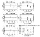
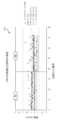
図14及び15は、本開示の方法によって達成される利点を示す。図14において、TPxtは、アッセイがマルチテスト形式(スライドあたり2回のテスト)のTP(「トータルプロテイン」)であることを意味する。COM(丸で示す)は、本開示の方法を用いて発見された標的位置で読み取った場合の精度を表す。PS(四角で示す)は、実際の吐出位置を知らずに、予め指定された中心(例えば、想定される吐出位置)で読み取った場合の精度を示す。各読み取り直径での変動係数(CV%)は、テストした全てのサンプルの平均である。Figures 14 and 15 show the advantages achieved by the disclosed method. In Figure 14, TPxt means that the assay is TP ("total protein") in multi-test format (two tests per slide). COM (shown as circles) represents the precision when reading at the target location found using the disclosed method. PS (shown as squares) represents the precision when reading at a pre-specified center (e.g., the expected dispense location) without knowing the actual dispense location. The coefficient of variation (CV%) at each read diameter is the average of all samples tested.
図16は、本開示の例示的な実施形態に従った、図1~図5の固体媒体10の実施形態を示す。図16の固体媒体10は、上で議論された滞留領域44に対応する2つの化学チップ1602aおよび1602bを含む。上述のように、滞留領域は、流体計量チップの開口部の直下にある化学チップの領域に対応する。滞留領域44はまた、半径方向の流体の流れがほとんどない、又は全くないことによって特徴付けられてもよい。スポット中心及び領域から半径方向に外側に位置し、化学チップの中心から離れた方向を指す流体流れベクトルが存在する。この領域には、ある程度の量の化学チップ試薬の洗い流しが存在する。滞留ゾーン又は領域44は、この洗い流しを経験せず、化学反応が完了すると、滞留領域44の外側の領域と比較して、異なる光学密度を有することができる。いくつかの例では、滞留ゾーン又は領域44は、有意なレベルの半径方向の流体の流れがなく、これにより、低い光学的変動性の領域および高い指示薬(色素)が存在する領域が生成される。1-5 in accordance with an exemplary embodiment of the present disclosure. The
いくつかの例では、化学チップ及び/又は滞留領域44は、反応セル内の流体サンプルの標的位置に対応する。標的位置又は化学チップは、反応セル内で試薬と反応する流体サンプル中の標的分子としての表示のために、指示薬が発現されるように、指示薬反応が起きる位置に対応する。いくつかの例では、化学チップ1602a及び1602bは、それぞれ、液体が充填された反応キュベットを含んでもよい。これらの例では、反応キュベットの画像化は、キュベット壁に気泡、破片、及び/又は傷を示す可能性がある。識別された欠陥は識別され、分析及びアッセイ結果に関連してその影響を緩和することができる。In some examples, the chemical chip and/or retention area 44 corresponds to a target location of the fluid sample in the reaction cell. The target location or chemical chip corresponds to a location where an indicator reaction occurs such that the indicator is expressed for indication as a target molecule in the fluid sample reacting with a reagent in the reaction cell. In some examples, the
化学チップ1602を使用することで、サンプルに必要な面積を減らし、スライド上に複数のサンプルを分散させることができる。化学チップ1602の各々は、同一の固体媒体10を用いた同一の又は異なる分析を可能にするために、サンプルから同一の流体を受け取ってもよい。あるいは、化学チップ1602の各々は、同じスライド10を用いた同一の又は異なる分析を可能にするために、異なる流体を受け取ってもよい。更に、図16は、2つの化学チップ1602を示すが、他の例では、固体媒体10は、3つ、4つ等の追加の化学チップを含んでもよい。固体媒体10上に複数の化学チップを含むことは、固体媒体を移動させることなく同じ固体媒体10上で複数の分析を行うことができるので、アッセイシステム20の操作効率を向上させることが理解されるべきである。対照的に、単一の化学チップのみを有する固体媒体は、複数の化学チップを有する単一の固体媒体10と同じ分析を実施するために、2つ以上の別個の固体媒体の処理を必要とする。The use of chemical chips 1602 reduces the area required for the sample and allows multiple samples to be distributed on the slide. Each of the chemical chips 1602 may receive the same fluid from the sample to allow for the same or different analyses using the same
図16は、化学製品固体媒体の組み合わせの例も示す。組み合わせは、トリグリセリド-コレステロール(TRI-CHOL)、総ビリルビン-アルカリホスファターゼ(TBIL-ALKP)、アラニンアミノトランスフェラーゼ-アスパラギン酸アミノトランスフェラーゼ(ALTV-AST)、尿素-クレアチニン(UREA-CREA)、グルコース-カルシウム(GLU-Ca)、及びアルブミン-トータルプロテイン(ALB-TP)を含む。他の組み合わせが固体媒体10上に作成され、実装され得ることが理解されるべきである。 16 also shows examples of chemical solid media combinations. The combinations include triglyceride-cholesterol (TRI-CHOL), total bilirubin-alkaline phosphatase (TBIL-ALKP), alanine aminotransferase-aspartate aminotransferase (ALTV-AST), urea-creatinine (UREA-CREA), glucose-calcium (GLU-Ca ), and albumin-total protein (ALB-TP). It should be understood that other combinations can be created and implemented on the
図17は、本開示の例示的な実施形態に従って、各々の固体媒体10の化学チップ1602上に配置されたサンプルを含む、図3のアッセイシステムによって記録された画像を示す。上述したように、流体のサンプルの吐出は、化学チップ1602上に液体レンズ46を形成する。図17の例示的な固体媒体10は、既知の従来のシングルスライド試験と比較して分析性能を維持しつつ、サンプルサイズを小さくし、アッセイシステム20の操作効率を高めるように構成されている。各々の化学チップ1602内に配置された小さなサンプル量のために、分析測定のための領域のサイズが小さくなる。いくつかの例では、アッセイシステム20は、可能性のある性能感度を緩和するために、上で議論したように、デジタル化学技術を使用してもよい。図17に示すように、デジタル化学は、波長が特異的なLEDを使用して、デジタル画像反射計に固体媒体10の画像を記録又は捕捉する。アッセイシステム20は、1つ以上の画像化アルゴリズムを使用して、測定位置の変動又は封じ込め物(例えば、埃)が存在しても、サンプルの最適領域の分析を確実にすることによって(上述したように)、化学的結果を改善する。17 shows an image recorded by the assay system of FIG. 3 including a sample placed on the chemical tip 1602 of each solid medium 10 according to an exemplary embodiment of the present disclosure. As described above, the ejection of the fluid sample forms a liquid lens 46 on the chemical tip 1602. The exemplary
図17に示すように、アッセイシステム20は、画像化アルゴリズムを使用して、それぞれのチップ1602a~1602dの中心40a~40dとして示される中心40を決定する。上述したように、中心40は、吐出先端及びスライドが完全に整列された場合の理論的なスポット中心であるデフォルトの中心と同じであってもよいし、そうでなくてもよい。次に、アッセイシステム20は、中心40の周囲の特定の半径を分析する。この半径は、図中の破線で示されるように、1mmから8mmの間、好ましくは約2.25mmである。As shown in FIG. 17, the
図18は、本開示の例示的な実施形態に従って、埃又は別の汚染物質1802がサンプルに含まれている図3のアッセイシステム20によって記録された画像1800を示す。図19は、本明細書に開示の方法を用いてアッセイシステム20によって実施された図18のサンプルの分析を示す。第1のグラフ1902は、異常1802が検出されて除去される前の分析結果を示す。第2のグラフ1904は、異常1802が検出され除去された後の分析結果を示す。図示された例では、画像化アルゴリズムが異常を検出し、処理された画像1906(図18の画像1800から導かれた)から異常を除去する。その結果、異常は、サンプルのその後の分析には含まれない。いくつかの例において、アッセイシステム20は、異常と関連付けられたピクセルカラーを、周囲のピクセルカラーと一致するカラー、又はその後の分析のためのデータがないことを示すピクセルカラーに変更することによって、異常を除去する。18 shows an
図20は、本開示の例示的な実施形態に従って、埃又は別の汚染物質がサンプルに含まれている、図3のアッセイシステム20によって記録された別の画像2000を示す。図21は、アッセイシステム20によって実施されたサンプルの分析を示す。第1のグラフ2102は、異常が検出されて除去される前の分析結果を示す。第2のグラフ2104は、異常が検出されて除去された後の分析結果を示す。前の例と同様に、画像化アルゴリズムは、異常を検出し、処理された画像2106(図20の画像2000から導かれた)から異常を除去する。その結果、異常は、サンプルのその後の分析には含まれない。加えて、アッセイシステム20は、分析フィールド(例えば、中心の周りの円)内に含まれる異常補正された位置の数を減少させる、又は最小化するように、画像2106の中心40を移動させるように構成されている。20 shows another
図22~図37は、図1~図21の例示的な固体媒体10の分析性能を既知のスライド又は固体媒体と比較した試験結果データを示す。図22及び図23の例示的な実施例では、固体媒体10はアッセイシステム20を用いて分析され、一方、既知のスライド又は固体媒体は既知の従来のアッセイシステムを用いて分析された。実施例において、2つの血清濃度に対する例示的な固体媒体10のうちの6つが、例示的なアッセイシステム20上の品質管理材料を用いて評価された。単一の較正のための性能の総ラボ内精度(分散係数(%CV)として報告された)を、CLSI EP05ガイドラインに従って、1日あたり2回の実施で、20日間にわたって1回の実施につき2回の複製で、合計80回の複製で評価した。アッセイシステム20によって分析された例示的な固体媒体10の最も悪いラボ内精度を、従来のアッセイシステムを使用して分析された対応する単一の先行技術の試験スライドと比較した。22-37 show test result data comparing the analytical performance of the exemplary
%CVはサンプルデータの平均に対する標準偏差の比率に相当し、アッセイの精度と再現性の指標を与え、低い値はより高い精度と再現性に対応する。The %CV corresponds to the ratio of the standard deviation of the sample data to the mean and gives an indication of the precision and reproducibility of the assay, with lower values corresponding to higher precision and reproducibility.
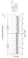
図22は、表2200の図であり、各スライド化学(UREA、TRIG、GLU、ALB、TBIL、ALTV、CREA、CHOL、CA、TP、ALKP、及びAST)についての2つの血清レベルと、従来のアッセイシステムを使用した先行技術のスライド及び例示的なアッセイシステム20を使用した例示的な固体媒体10とについての対応する%CVを示す。図示のように、24の異なる試験のうち、アッセイシステム20を使用した固体媒体10は、24の異なる試験のうちの19の試験において、より低い%CVを有していた。図23は、グラフ2300を示し、既知の先行技術のスライドと、アッセイシステム20を使用して分析された本明細書に開示の例示的な固体媒体10との間の、異なるスライド化学試験のそれぞれについての%CVの差を示す。図示のように、アッセイシステム20を用いて例示的な固体媒体10を使用することは、先行技術のスライドと比較して、ほとんどのスライド化学試験においてより良好な%CVを提供した。Figure 22 is a diagram of table 2200 showing two serum levels for each slide chemistry (UREA, TRIG, GLU, ALB, TBIL, ALTV, CREA, CHOL, CA, TP, ALKP, and AST) and the corresponding %CV for the prior art slides using the conventional assay system and the exemplary solid medium 10 using the
図24~図37の例示的な実施例では、外部精度試験を実施した。この試験では、先行技術の試験スライドを、従来のアッセイシステムを用いて分析した。12のケミストリーを有するテストスライドを、2つの血清濃度について分析した。統計的データの外れ値は分析から除去した。残りのデータについてShapiro-Wilk正規性検定を実行し、正規性からの重大な逸脱を示すセットを削除した。各スライドの血清と試薬のロットの組み合わせについて%CVを計算した。%CV測定値は、試薬ロット内で平均化され、例示的なアッセイシステム20で分析された例示的な固体媒体(10)のラボ内でのより悪い精度と比較した。In the exemplary examples of Figures 24-37, an external precision study was performed. In this study, prior art test slides were analyzed using a conventional assay system. Test slides with 12 chemistries were analyzed for two serum concentrations. Statistical data outliers were removed from the analysis. A Shapiro-Wilk normality test was performed on the remaining data, and sets showing significant departures from normality were removed. %CV was calculated for each slide serum and reagent lot combination. %CV measurements were averaged within reagent lots and compared to the worse intra-laboratory precision of the exemplary solid media (10) analyzed with the
図24は、表2400の図を示し、各スライド化学(UREA、TRIG、GLU、ALB、TBIL、ALTV、CREA、CHOL、CA、TP、ALKP、およびAST)についての2つの血清レベル、及び、従来のアッセイシステムを使用した先行技術のスライドと、例示的なアッセイシステム20を使用した例示的な固体媒体10と、についての対応する%CVを示す。図示されているように、24の異なる試験のうち、アッセイシステム20を使用した固体媒体10は、24の異なる試験のうちの20において、より低い%CVを有した。図25は、グラフ2500を示し、アッセイシステム20を使用して分析された、既知の先行技術のスライドと本明細書に開示の例示的な固体媒体10との間の、異なるスライド化学試験のそれぞれについての%CV差を示す。Figure 24 shows a diagram of table 2400 showing two serum levels for each slide chemistry (UREA, TRIG, GLU, ALB, TBIL, ALTV, CREA, CHOL, CA, TP, ALKP, and AST) and the corresponding %CV for the prior art slides using the conventional assay system and the exemplary solid medium 10 using the
図26~37は、例示的な固体媒体10及び既知の先行技術のスライドについての各試薬ロット番号についての結果を示すグラフを示す。グラフにおいて、固体媒体10は、3つのロットが提供され、「XT・・・ロット番号」と称される。加えて、先行技術スライドに関連するデータは、「ST・・・ フィールド由来」および「ST平均」と称される。それぞれのグラフは、血清(PVI)および(PVII)のそれぞれについての精度%CVを提供する。Figures 26-37 show graphs depicting results for each reagent lot number for an exemplary solid medium 10 and known prior art slides. In the graphs,
図26のグラフ2600は、アッセイシステム20によって分析された例示的な固体媒体10が、従来のアッセイシステムによって分析された先行技術のスライドと比較して、TRIGスライド化学試薬のための低い%CVを有していたことを示す。図27のグラフ2700は、アッセイシステム20によって分析された例示的な固体媒体10が、従来のシステムによって分析された既知の先行技術のスライドと比較して、わずかに高い%CVを有するPVI血清のロット3を除き、CHOLスライド化学試薬についてより低い%CVを有していたことを示す。図28のグラフ2800は、アッセイシステム20によって分析された例示的な固体媒体10が、従来のアッセイシステムによって分析された先行技術のスライドと比較して、GLUスライド化学試薬について低い%CVを有していたことを示している。図29のグラフ2900は、アッセイシステム20によって分析された例示的な固体媒体10が、従来のアッセイシステムによって分析された先行技術のスライドと比較して、CAスライド化学試薬について低い%CVを有していたことを示す。
更に、図30のグラフ3000は、アッセイシステム20によって分析された例示的な固体媒体10が、従来のアッセイシステムによって分析された先行技術のスライドと比較して、TPスライド化学試薬について低い%CVを有していたことを示す。図31のグラフ3100は、アッセイシステム20によって分析された例示的な固体媒体10が、従来のアッセイシステムによって分析された先行技術のスライドと比較して、ALBスライド化学試薬について低い%CVを有していたことを示す。図32のグラフ3200は、アッセイシステム20によって分析された例示的な固体媒体10が、従来のアッセイシステムによって分析された先行技術のスライドと比較して、ALVスライド化学試薬について低い%CVを有していたことを示す。図33のグラフ3300は、アッセイシステム20によって分析された例示的な固体媒体10が、従来のアッセイシステムによって分析された先行技術のスライドと比較して、ASTスライド化学試薬について低い%CVを有していたことを示す。Furthermore,
図34のグラフ3400は、アッセイシステム20によって分析された例示的な固体媒体10が、従来のアッセイシステムによって分析された先行技術のスライドと比較して、UREAスライド化学試薬について高い%CVを有していたことを示している。しかし、例示的なシステムと従来システムとの間の%CVの差は0.5%未満である。図35のグラフ3500は、アッセイシステム20によって分析された例示的な固体媒体10が、従来のアッセイシステムによって分析された先行技術のスライドと比較して、CREAスライド化学試薬について低い%CVを有していたことを示す。図36のグラフ3600は、アッセイシステム20によって分析された例示的な固体媒体10が、従来のアッセイシステムによって分析された先行技術のスライドと比較して、ALKPスライド化学試薬について、%CVがほぼ等しい、又は低いことを示す。図37のグラフ3700は、アッセイシステム20によって分析された例示的な固体媒体10が、従来のアッセイシステムによって分析された先行技術のスライドと比較して、TBILスライド化学試薬について低い%CVを有していたことを示す。
(結論)
本明細書に記載された現在好ましい実施形態に対する様々な変更および修正は、当業者には明らかであることが理解されるべきである。そのような変更および修正は、本主題の精神及び範囲から逸脱することなく、またその意図された利点を減じることなく行うことができる。従って、そのような変更および修正は、添付の請求項によって含められることが意図される。(Conclusion)
It should be understood that various changes and modifications to the presently preferred embodiments described herein will be apparent to those skilled in the art. Such changes and modifications can be made without departing from the spirit and scope of the present subject matter and without diminishing its intended advantages. Accordingly, such changes and modifications are intended to be covered by the appended claims.
他が示されていない限り、本明細書及び請求項で使用される成分の量、分子量、反応条件等の特性を表す全ての数値は、全ての場合において、「約」という用語によって修正されているものとして理解されるべきである。従って、反対が示されていない限り、以下の明細書および添付の請求項に記載された数値パラメータは、本開示によって得られるように求められる所望の特性に応じて変化し得る近似値である。少なくとも、特許請求の範囲への等価性の原則の適用を制限する試みとしてではなく、各数値パラメータは、少なくとも、報告された有効数字の数に照らして、通常の四捨五入を適用して解釈されるべきである。本開示の広い範囲を規定する数値範囲及びパラメータは近似値であるにも関わらず、特定の実施例に規定された数値は、可能な限り正確に報告されている。しかしながら、任意の数値は、本質的に、それぞれの試験測定において見出された標準偏差から必然的に生じる一定の誤差を含んでいる。Unless otherwise indicated, all numerical values expressing properties such as amounts of ingredients, molecular weights, reaction conditions, and the like used in the specification and claims should be understood in all instances as being modified by the term "about." Accordingly, unless indicated to the contrary, the numerical parameters set forth in the following specification and appended claims are approximations that may vary depending on the desired properties sought to be obtained by the present disclosure. At the very least, and not as an attempt to limit the application of the doctrine of equivalence to the scope of the claims, each numerical parameter should at least be construed in light of the number of reported significant digits and by applying ordinary rounding approaches. Notwithstanding that the numerical ranges and parameters setting forth the broad scope of the present disclosure are approximations, the numerical values set forth in the specific examples are reported as precisely as possible. Any numerical values, however, inherently contain certain errors necessarily resulting from the standard deviation found in their respective testing measurements.
本開示の文脈(特に以下の請求項の文脈)で使用される用語「a」、「an」、「the」、および類似の指示対象は、本明細書に別段の記載がない限り、または文脈によって明確に矛盾しない限り、単数形および複数形の両方を含むように解釈されるべきである。本明細書での値の範囲の限定は、範囲内に該当する各個別の値を個々に参照するための簡単な方法として機能することを単に意図する。本明細書に他が示されていない限り、個々の値は、それが個々に本明細書に引用されているかのように本明細書に組み込まれる。本明細書に記載されたすべての方法は、本明細書に他が示されていない限り、又は明確に文脈と矛盾しない限り、任意の適切な順序で実施することができる。本明細書で提供される任意の及び全ての例示的な、又は例示的な言語(例えば、「のような」)の使用は、単に開示をより明らかにすることを意図するものであり、主張する開示の範囲に制限を与えるものではない。本明細書中のいかなる言葉は、本開示の実施に不可欠な請求されていない要素を示すとして解釈されるべきではない。As used in the context of this disclosure (particularly in the context of the claims below), the terms "a," "an," "the," and similar referents should be construed to include both the singular and the plural, unless otherwise indicated herein or clearly contradicted by context. Limitations of value ranges herein are merely intended to serve as a shorthand method for individually referring to each separate value falling within the range. Unless otherwise indicated herein, each separate value is incorporated herein as if it were individually recited herein. All methods described herein can be performed in any suitable order, unless otherwise indicated herein or clearly contradicted by context. The use of any and all exemplary or illustrative language (e.g., "such as") provided herein is intended merely to clarify the disclosure and does not pose a limitation on the scope of the claimed disclosure. No language in the specification should be construed as indicating any non-claimed element essential to the practice of the disclosure.
特許請求の範囲における用語「又は」の使用は、代替物のみを参照することを明示的に示さない限り、又は代替物が相互に排他的である場合を除き、「及び/又は」を意味するために使用されるが、本開示は、代替物のみ及び「及び/又は」を指す定義をサポートする。The use of the term "or" in the claims is used to mean "and/or" unless expressly indicated to refer to alternatives only or the alternatives are mutually exclusive, however, the present disclosure supports a definition that refers to alternatives only and "and/or."
本明細書に開示される開示の代替要素または実施形態のグループ化は、制限として解釈されるべきではない。各グループの要素は、個別に、又はグループの他の要素又は本明細書で見出される他の要素との任意の組み合わせで参照され、主張され得る。便宜上及び/又は特許性の理由から、グループの1つ又は複数の要素がグループに含まれるか、又はグループから削除されてもよいことが予期される。そのような包含又は削除が生じる場合、本明細書では、修正されたグループを含むものとみなされ、従って、添付の請求項で使用されるすべてのマーカッシュグループの書面による説明を満たす。Groupings of alternative elements or embodiments of the disclosure disclosed herein are not to be construed as limitations. The elements of each group may be referenced and claimed individually or in any combination with other elements of the group or other elements found herein. It is anticipated that one or more elements of a group may be included in, or deleted from, a group for reasons of convenience and/or patentability. When such inclusion or deletion occurs, the specification is deemed to include the modified group, and therefore satisfies the written description of all Markush groups used in the appended claims.
本開示の好ましい実施形態は、本開示を実施するために本発明者らに知られている最良の態様を含めて、本明細書に記載されている。当然ながら、これらの好ましい実施形態の変形例は、前述の説明を読むことで、当業者には明らかになるであろう。本発明者は、当業者が、そのような変形例を適宜採用することを予期しており、本発明者は、本開示が、本明細書に具体的に記載されている以外の方法で実施されることを意図している。従って、本開示は、適用される法により許容されるように、添付の特許請求の範囲に記載された主題の全ての改変及び均等物を含む。更に、本明細書に別段の記載がない限り、又は文脈から明確に矛盾する場合を除き、上述した要素のあらゆる可能な変形例の組み合わせが、本開示によって包含される。Preferred embodiments of the present disclosure are described herein, including the best mode known to the inventors for carrying out the disclosure. Of course, variations of these preferred embodiments will become apparent to those of skill in the art upon reading the foregoing description. The inventors anticipate that such variations will be adopted by those of skill in the art as appropriate, and the inventors intend that the present disclosure may be practiced otherwise than as specifically described herein. Accordingly, this disclosure includes all modifications and equivalents of the subject matter recited in the claims appended hereto as permitted by applicable law. Moreover, all possible combinations of the elements described above in any possible variations are encompassed by the present disclosure unless otherwise indicated herein or clearly contradicted by context.
本明細書に開示された特定の実施形態は、請求項において、「からなる」または「本質的にからなる」という語を用いてさらに限定され得る。請求項中で使用される場合、出願時又は補正時に追加されたかを問わず、移行用語「からなる」は、請求項中で指定されていない任意の要素、ステップ、又は成分を除外する。「本質的にからなる」という移行用語は、請求項の範囲を、指定された材料又はステップ、且つ基本的及び新規な特性に実質的に影響を与えないものに限定する。本開示の請求される実施形態は、本明細書に本質的に又は明示的に記載され、そして可能にされる。Certain embodiments disclosed herein may be further limited in the claims using the terms "consisting of" or "consisting essentially of." When used in a claim, whether added at the time of filing or in an amendment, the transitional term "consisting of" excludes any element, step, or ingredient not specified in the claim. The transitional term "consisting essentially of" limits the scope of the claim to those materials or steps specified and that do not materially affect the basic and novel characteristics. The claimed embodiments of the present disclosure are essentially or explicitly described and enabled herein.
更に、本明細書に開示された本開示の実施形態は、本開示の原理を例示するものであることが理解される。採用され得る他の改変は、本開示の範囲内である。従って、例示的であるが、これに限定されるものではなく、本開示の代替的な構成が、本明細書の教示に従って利用され得る。従って、本開示は、示され、記載されているものに正確に限定されない。Furthermore, it is understood that the embodiments of the present disclosure disclosed herein are illustrative of the principles of the present disclosure. Other modifications that may be employed are within the scope of the present disclosure. Thus, by way of example, but not limitation, alternative configurations of the present disclosure may be utilized in accordance with the teachings herein. Thus, the present disclosure is not limited to that precisely as shown and described.
[付記]
[付記1]
制御ユニットにおいて、反応セル上に位置する流体サンプルの少なくとも1つの画像を得るステップ、
前記制御ユニットを介して、前記少なくとも1つの画像に基づいて複数の微分データ点を含む微分データのセットを作成するステップ、
前記制御ユニットを介して、それぞれの前記複数の微分データ点のための画像勾配データ点を決定するステップ、
前記制御ユニットを介して、前記画像勾配データ点に基づいて、前記反応セル内の前記流体サンプルの標的位置を決定するステップ、及び、
前記制御ユニット及び関連するアッセイシステムを介して、前記反応セル内の前記流体サンプルの前記標的位置を使用して少なくとも1つのアッセイを実施するステップ、
を含む、少なくとも1つのアッセイを実施する方法。[Additional Notes]
[Appendix 1]
obtaining, in the control unit, at least one image of the fluid sample located on the reaction cell;
generating, via the control unit, a set of differential data based on the at least one image, the set including a plurality of differential data points;
determining, via said control unit, an image gradient data point for each of said plurality of differential data points;
determining, via the control unit, a target position of the fluid sample within the reaction cell based on the image gradient data points; and
performing, via said control unit and an associated assay system, at least one assay using said target location of said fluid sample within said reaction cell;
A method of performing at least one assay comprising:
[付記2]
前記反応セルは、固体媒体、乾燥スライド、又は反応キュベットを含む、
ことを特徴とする付記1に記載の方法。[Appendix 2]
The reaction cell comprises a solid medium, a dry slide, or a reaction cuvette.
2. The method according to
[付記3]
前記標的位置は、前記反応セル内の前記流体サンプルの均一領域のほぼ中心を含む、
ことを特徴とする付記1又は2に記載の方法。[Appendix 3]
the target location comprises an approximate center of a uniform region of the fluid sample within the reaction cell;
3. The method according to
[付記4]
複数の画像からの標的位置を使用して、複数のアッセイを実施するステップを含む、
ことを特徴とする付記1、2又は3に記載の方法。[Appendix 4]
performing a plurality of assays using target locations from the plurality of images;
4. The method according to
[付記5]
前記微分データ点は、前記少なくとも1つの画像における色に基づく一次微分である、
ことを特徴とする付記1、2、3又は4に記載の方法。[Appendix 5]
the derivative data points are first derivatives based on color in the at least one image;
5. The method according to
[付記6]
前記流体サンプルの前記標的位置を決定するステップは、
(i)第2の画像勾配データ点よりも低い画像勾配を有する第1の画像勾配データ点を使用すること、又は、
(ii)第1の画像勾配データ点よりも高い画像勾配を有する第2の画像勾配データ点を除外すること、
の少なくとも1つを含む、
ことを特徴とする付記1、2、3、4又は5に記載の方法。[Appendix 6]
The step of determining the target location of the fluid sample comprises:
(i) using a first image gradient data point having a lower image gradient than a second image gradient data point; or
(ii) excluding second image gradient data points having a higher image gradient than the first image gradient data points;
At least one of
6. The method according to
[付記7]
前記制御ユニットを介して、前記少なくとも1つの画像から画像の欠陥を除去するステップ、を含む、
ことを特徴とする付記1又は6に記載の方法。[Appendix 7]
removing image defects from the at least one image via the control unit.
7. The method according to
[付記8]
前記少なくとも1つの画像は2次元画像である、
ことを特徴とする付記1又は7に記載の方法。[Appendix 8]
said at least one image being a two-dimensional image;
8. The method according to
[付記9]
前記制御ユニットを介して、前記標的位置周辺の読み取り領域を形成するステップを含み、少なくとも1つのアッセイを実施するステップは、前記読み取り領域を使用することを含む、
ことを特徴とする付記1又は8に記載の方法。[Appendix 9]
forming, via the control unit, a read area around the target location, and performing at least one assay includes using the read area.
9. The method according to
[付記10]
前記流体サンプルの前記標的位置を決定するステップは、前記流体サンプルと結合する少なくとも1つの試薬から形成された、前記反応セル内の指示薬分子の指示薬反応を検出すること又は測定することを含む、
ことを特徴とする付記1に記載の方法。[Appendix 10]
determining the target location of the fluid sample includes detecting or measuring an indicator reaction of an indicator molecule in the reaction cell formed from at least one reagent that binds to the fluid sample;
2. The method according to
[付記11]
制御ユニットを介して、反応セル上に位置する流体サンプルの少なくとも1つの画像を得るステップ、
前記制御ユニットを介して、前記少なくとも1つの画像に基づいて、複数の微分データ点を含む微分データのセットを作成するステップ、
前記制御ユニットを介して、前記複数の微分データ点に基づき、前記流体サンプルの標的位置を決定するステップ、
前記制御ユニットを介して、前記標的位置の周辺の読み取り領域を形成するステップ、及び、
前記制御ユニット及び関連するアッセイシステムを介して、前記読み取り領域を使用して、少なくとも1つのアッセイを実施するステップ、
を含む、
少なくとも1つのアッセイを実施する方法。[Appendix 11]
obtaining, via the control unit, at least one image of the fluid sample located on the reaction cell;
generating, via said control unit, a set of differential data based on said at least one image, said set including a plurality of differential data points;
determining, via the control unit, a target location for the fluid sample based on the plurality of differential data points;
forming, via the control unit, a reading area around the target location; and
performing at least one assay using said read area via said control unit and associated assay system;
Including,
A method for performing at least one assay.
[付記12]
前記反応セルは、固体媒体、乾燥スライド、又は反応キュベットを含む、
ことを特徴とする付記11に記載の方法。[Appendix 12]
The reaction cell comprises a solid medium, a dry slide, or a reaction cuvette.
12. The method according to claim 11,
[付記13]
前記読み取り領域は、少なくとも1つの画像内で、ほぼ円形を示す、
ことを特徴とする付記11又は12に記載の方法。[Appendix 13]
The reading area exhibits a substantially circular shape in at least one image.
13. The method according to claim 11 or 12,
[付記14]
前記読み取り領域は、前記少なくとも1つの画像で、ほぼ楕円形に表示される、
ことを特徴とする付記11、12又は13に記載の方法。[Appendix 14]
the reading area is displayed in the at least one image as a substantially oval shape;
14. The method according to
[付記15]
前記制御ユニットを介して、それぞれの前記複数の微分データ点のための画像勾配データ点を決定するステップ、及び、前記画像勾配データ点に基づいて前記流体サンプルの前記標的位置を決定するステップ、を含む、
ことを特徴とする付記11、12、13又は14に記載の方法。[Appendix 15]
determining, via the control unit, an image gradient data point for each of the plurality of differential data points; and determining the target location of the fluid sample based on the image gradient data points.
15. The method according to
[付記16]
前記制御ユニット及び前記関連するアッセイシステムを介して、複数のイメージに由来する標的位置を使用して、複数のアッセイを実施することを含む、
ことを特徴とする付記11又は15に記載の方法。[Appendix 16]
performing, via said control unit and said associated assay system, a plurality of assays using target locations derived from the plurality of images.
16. The method according to claim 11 or 15,
[付記17]
前記少なくとも1つの画像は、2次元画像である、
ことを特徴とする付記11又は16に記載の方法。[Appendix 17]
The at least one image is a two-dimensional image.
17. The method according to claim 11 or 16,
[付記18]
流体サンプルが位置された少なくとも1つの反応セルを受容するように構成されたスライド受容位置、
前記反応セル内に位置する前記流体サンプルの少なくとも1つの画像を得るために、前記スライド受容位置に対して置かれ及び配置される画像装置、及び、
(i)前記少なくとも1つの画像からの微分データ点を分析することで、前記反応セル内に位置する前記流体サンプル内の標的位置を決定する、及び(ii)前記標的位置に基づいて少なくとも1つのアッセイを実施するように構成された制御ユニット、
を備える、少なくとも1つのアッセイを実施するための装置。[Appendix 18]
a slide receiving location configured to receive at least one reaction cell having a fluid sample positioned therein;
an imaging device located and positioned relative to the slide receiving location to obtain at least one image of the fluid sample located within the reaction cell; and
a control unit configured to (i) determine a target location within the fluid sample located in the reaction cell by analyzing differential data points from the at least one image; and (ii) perform at least one assay based on the target location;
16. An apparatus for performing at least one assay comprising:
[付記19]
前記反応セルは、固体媒体、乾燥スライド、又は反応キュベットを含む、
ことを特徴とする付記18に記載の装置。[Appendix 19]
The reaction cell comprises a solid medium, a dry slide, or a reaction cuvette.
19. The apparatus of claim 18.
[付記20]
前記固体媒体は、第2の反応セルを含む、
ことを特徴とする付記19に記載の装置。[Appendix 20]
The solid medium comprises a second reaction cell.
20. The apparatus of claim 19.
[付記21]
前記標的位置は、前記流体サンプルの均一領域のほぼ中心位置を含む、
ことを特徴とする付記18又は20に記載の装置。[Appendix 21]
the target location comprises an approximate center location of a uniform region of the fluid sample;
21. The device according to claim 18 or 20.
[付記22]
前記制御ユニットは、それぞれの複数の前記微分データ点のための画像勾配データ点を分析することで、前記標的位置を決定するように構成される、
ことを特徴とする付記18、19、20、又は21に記載の装置。[Appendix 22]
the control unit is configured to determine the target location by analyzing image gradient data points for each of the plurality of differential data points.
22. The device of
[付記23]
(i)第2の画像勾配データ点よりも低い画像勾配を有する第1の画像勾配データ点を使用する、又は、(ii)第1の画像勾配データ点よりも高い画像勾配を有する第2の画像勾配データ点を除外する、の少なくとも1つによって、前記標的位置を決定するように、前記制御ユニットは構成される、
ことを特徴とする付記22に記載の装置。[Appendix 23]
the control unit is configured to determine the target location by at least one of: (i) using a first image gradient data point having a lower image gradient than a second image gradient data point; or (ii) excluding a second image gradient data point having a higher image gradient than the first image gradient data point.
23. The apparatus of
[付記24]
制御ユニットは、第2の画像勾配データ点よりも低い画像勾配を有する第1の画像勾配データ点のほぼ幾何学的中心で前記標的位置を決定するように、構成される、
ことを特徴とする付記22に記載の装置。[Appendix 24]
the control unit is configured to determine the target location at approximately a geometric center of a first image gradient data point having a lower image gradient than a second image gradient data point.
23. The apparatus of
[付記25]
前記制御ユニットは、複数の画像からの標的位置を使用して、複数の異なるアッセイを実施するように構成されている、
ことを特徴とする付記18又は25に記載の装置。[Appendix 25]
the control unit is configured to perform a plurality of different assays using target locations from the plurality of images.
26. The device according to claim 18 or 25.
[付記26]
前記反応セル内の前記流体サンプルの前記標的位置は、前記反応セル内で前記流体サンプル中の標的分子が試薬と反応するにつれて指示薬が表示のために発現するように指示薬反応が起こる位置に対応する、
ことを特徴とする付記18又は25に記載の装置。[Appendix 26]
the target location of the fluid sample within the reaction cell corresponds to a location within the reaction cell where an indicator reaction occurs such that as target molecules in the fluid sample react with a reagent within the reaction cell, an indicator is developed for indication;
26. The device according to claim 18 or 25.
Claims (25)
Translated fromJapanese前記制御ユニットを介して、前記反応セルの中心と、前記反応セル上への前記流体サンプルの吐出位置の中心と、のうち少なくとも一方に対応するデフォルト中心を決定するステップ、
前記制御ユニットを介して、前記画像に基づいて複数の微分データ点を含む微分データのセットを生成するステップ、
前記制御ユニットを介して、それぞれの前記複数の微分データ点のための画像勾配データ点を決定し、二値画像を生成するステップであって、
それぞれの前記複数の微分データ点を閾値と比較し、
閾値と比較して大きい値を有する前記微分データ点に対応する前記画像勾配データ点に「0」の値を与えて、不要な画像アーチファクトを除去し、及び
残存させる前記画像勾配データ点に「1」の値を与える、
ことによるステップ、
前記制御ユニットを介して、前記画像勾配データ点を使用して、前記二値画像の重心を決定するステップ、
前記制御ユニットを介して、前記反応セル上の前記流体サンプルの標的位置として、決定された前記重心を指定するステップ、
前記制御ユニットを介して、前記標的位置と、前記デフォルト中心とを比較するステップ、及び、
前記制御ユニット及び関連するアッセイシステムを介して、前記デフォルト中心と前記標的位置との距離が閾値より小さい場合に前記反応セル上の前記流体サンプルの前記標的位置を使用して少なくとも1つのアッセイを実施するステップ、
を含む、少なくとも1つのアッセイを実施する方法。 obtaining, in the control unit, an image of the fluid sample located on the reaction cell;
determining, via the control unit, a default center corresponding to at least one of a center of the reaction cell and a center of a dispensing position of the fluid sample onto the reaction cell;
generating, via the control unit, a set of differential data based on the image, the set including a plurality of differential data points;
determining, via the control unit, an image gradient data point for each of the plurality of differential data points to generate a binary image;
comparing each of the plurality of differential data points to a threshold;
assigning a value of "0" to the image gradient data points corresponding to the derivative data points having values large compared to a threshold to remove unwanted image artifacts; and assigning a value of "1" to the image gradient data points that are to be retained.
Steps by
determining, via said control unit, a centroid of said binary image using said image gradient data points;
designating, via the control unit, the determined centroid as a target position for the fluid sample on the reaction cell;
comparing, via the control unit, the target position with the default center; and
via said control unit and an associated assay system, performing at least one assay using said target position of said fluid sample on said reaction cell if the distance between said default center and said target position is less than a threshold value;
2. A method for performing at least one assay comprising:
ことを特徴とする請求項1に記載の方法。 The reaction cell comprises a solid medium, a dry slide, or a reaction cuvette.
2. The method of claim 1 .
ことを特徴とする請求項1に記載の方法。 the target location includes a center of a uniform area of the fluid sample on the reaction cell;
2. The method of claim 1 .
ことを特徴とする請求項1に記載の方法。 performing a plurality of assays using target locations from the plurality of images;
2. The method of claim 1 .
ことを特徴とする請求項1に記載の方法。 the plurality of derivative data points are first derivatives based on color in the image;
2. The method of claim 1 .
(i)第2の画像勾配データ点よりも低い画像勾配を有する第1の画像勾配データ点を使用すること、又は、
(ii)第1の画像勾配データ点よりも高い画像勾配を有する第2の画像勾配データ点を除外すること、
の少なくとも1つを含む、
ことを特徴とする請求項1に記載の方法。 The step of determining a centroid of the binary image comprises:
(i) using a first image gradient data point having a lower image gradient than a second image gradient data point; or
(ii) excluding second image gradient data points having a higher image gradient than the first image gradient data points;
At least one of
2. The method of claim 1 .
ことを特徴とする請求項1に記載の方法。 removing image defects from the image via the control unit.
2. The method of claim 1 .
ことを特徴とする請求項1に記載の方法。 The image is a two-dimensional image.
2. The method of claim 1 .
ことを特徴とする請求項1に記載の方法。 forming, via the control unit, a read area around the target location, and performing the at least one assay includes using the read area.
2. The method of claim 1 .
ことを特徴とする請求項1に記載の方法。 obtaining an image of the fluid sample includes detecting or measuring an indicator reaction of an indicator molecule on the reaction cell formed from at least one reagent that binds with the fluid sample;
2. The method of claim 1 .
前記制御ユニットを介して、前記反応セルの中心と、前記反応セル上への前記流体サンプルの吐出位置の中心と、のうち少なくとも一方に対応するデフォルト中心を決定するステップ、
前記制御ユニットを介して、前記画像に基づいて複数の微分データ点を含む微分データのセットを生成するステップ、
前記制御ユニットを介して、それぞれの前記複数の微分データ点のための画像勾配データ点を決定し、二値画像を生成するステップであって、
それぞれの前記複数の微分データ点を閾値と比較し、
閾値と比較して大きい値を有する前記微分データ点に対応する前記画像勾配データ点に「0」の値を与えて、不要な画像アーチファクトを除去し、及び
残存させる前記画像勾配データ点に「1」の値を与える、
ことによるステップ、
前記制御ユニットを介して、前記画像勾配データ点を使用して、前記二値画像の重心を決定するステップ、
前記制御ユニットを介して、前記流体サンプルの標的位置として、決定された前記重心を指定するステップ、
前記制御ユニットを介して、前記標的位置の周辺の読み取り領域を形成するステップ、
前記制御ユニットを介して、前記標的位置と、前記デフォルト中心とを比較するステップ、及び、
前記制御ユニット及び関連するアッセイシステムを介して、前記デフォルト中心と前記標的位置との距離が閾値より小さい場合に前記読み取り領域を使用して少なくとも1つのアッセイを実施するステップ、
を含む、
少なくとも1つのアッセイを実施する方法。 obtaining, via the control unit, an image of the fluid sample located on the reaction cell;
determining, via the control unit, a default center corresponding to at least one of a center of the reaction cell and a center of a dispensing position of the fluid sample onto the reaction cell;
generating, via the control unit, a set of differential data based on the image, the set including a plurality of differential data points;
determining, via the control unit, an image gradient data point for each of the plurality of differential data points to generate a binary image;
comparing each of the plurality of differential data points to a threshold;
assigning a value of "0" to the image gradient data points corresponding to the derivative data points having values large compared to a threshold to remove unwanted image artifacts; and assigning a value of "1" to the image gradient data points that are to be retained.
Steps by
determining, via said control unit, a centroid of said binary image using said image gradient data points;
designating, via the control unit, the determined centroid as a target location for the fluid sample;
forming, via said control unit, a reading area around said target location;
comparing, via the control unit, the target position with the default center; and
via said control unit and associated assay system, performing at least one assay using said read area if the distance between said default center and said target location is less than a threshold value;
Including,
A method for performing at least one assay.
ことを特徴とする請求項11に記載の方法。 The reaction cell comprises a solid medium, a dry slide, or a reaction cuvette.
12. The method of claim 11 .
ことを特徴とする請求項11に記載の方法。 The reading area represents a circular shape in the image.
12. The method of claim 11 .
ことを特徴とする請求項11に記載の方法。 The reading area is displayed as an oval in the image.
12. The method of claim 11 .
ことを特徴とする請求項11に記載の方法。 performing, via said control unit and said associated assay system, a plurality of assays using target locations derived from the plurality of images.
12. The method of claim 11 .
ことを特徴とする請求項11に記載の方法。 The image is a two-dimensional image.
12. The method of claim 11 .
前記反応セル上に位置する前記流体サンプルの画像を得るために、前記スライド受容位置に対して置かれ及び配置される画像装置と、
前記反応セルの中心と、前記反応セル上への前記流体サンプルの吐出位置の中心と、のうち少なくとも一方に対応するデフォルト中心を決定し、
前記画像に基づいて複数の微分データ点を含む微分データのセットを生成し、
それぞれの前記複数の微分データ点のために画像勾配データ点を決定して、二値画像を生成することであって、
それぞれの前記複数の微分データ点を閾値と比較し、
閾値と比較して大きい値を有する前記微分データ点に対応する前記画像勾配データ点に「0」の値を与えて、不要な画像アーチファクトを除去し、及び
残存させる前記画像勾配データ点に「1」の値を与える、
ことによって該二値画像を生成し、
前記画像勾配データ点を使用して前記二値画像の重心を決定し、
前記反応セル上に位置する前記流体サンプル内の標的位置として、決定された前記重心を指定し、
前記標的位置と前記デフォルト中心とを比較し、及び、
前記デフォルト中心と前記標的位置との距離が閾値より小さい場合に、前記標的位置に基づいて少なくとも1つのアッセイを実施する、
ように構成された制御ユニットと、
を備える、少なくとも1つのアッセイを実施するための装置。 a slide receiving location configured to receive at least one reaction cell having a fluid sample disposed therein;
an imaging device positioned and arranged relative to the slide receiving location to obtain an image of the fluid sample located on the reaction cell;
determining a default center corresponding to at least one of a center of the reaction cell and a center of a dispensing position of the fluid sample onto the reaction cell;
generating a set of differential data based on the image, the set including a plurality of differential data points;
determining an image gradient data point for each of the plurality of differential data points to generate a binary image;
comparing each of the plurality of differential data points to a threshold;
assigning a value of "0" to the image gradient data points corresponding to the derivative data points having values large compared to a threshold to remove unwanted image artifacts; and assigning a value of "1" to the image gradient data points that are to be retained.
generating the binary image by
determining a centroid of said binary image using said image gradient data points;
designating the determined centroid as a target location within the fluid sample located above the reaction cell;
Comparing the target location to the default center; and
performing at least one assay based on the target location if the distance between the default center and the target location is less than a threshold value;
A control unit configured as described above.
16. An apparatus for performing at least one assay comprising:
ことを特徴とする請求項17に記載の装置。 The reaction cell comprises a solid medium, a dry slide, or a reaction cuvette.
20. The apparatus of claim17 .
ことを特徴とする請求項18に記載の装置。 The solid medium comprises a second reaction cell.
20. The apparatus of claim18 .
ことを特徴とする請求項17に記載の装置。 the target location comprises a center location of a uniform region of the fluid sample;
20. The apparatus of claim17 .
勾配データ点を除外する、の少なくとも1つによって、前記標的位置を決定するように、前記制御ユニットは構成される、
ことを特徴とする請求項17に記載の装置。 the control unit is configured to determine the target location by at least one of: (i) using a first image gradient data point having a lower image gradient than a second image gradient data point; or (ii) excluding a second image gradient data point having a higher image gradient than the first image gradient data point.
20. The apparatus of claim17 .
ことを特徴とする請求項17に記載の装置。 the control unit is configured to determine the target location at a geometric center of a first image gradient data point having a lower image gradient than a second image gradient data point.
20. The apparatus of claim17 .
ことを特徴とする請求項17に記載の装置。 the control unit is configured to perform a plurality of different assays using target locations from the plurality of images.
20. The apparatus of claim17 .
ことを特徴とする請求項17に記載の装置。 the target location of the fluid sample on the reaction cell corresponds to a location on the reaction cell where an indicator reaction occurs such that as target molecules in the fluid sample react with a reagent, an indicator is developed for indication;
20. The apparatus of claim17 .
ことを特徴とする請求項1に記載の方法。 and reporting, via the control unit, an error indicating that a new fluid sample should be dispensed onto a new reaction cell if the distance between the default center and the target location is equal to or greater than a threshold value.
2. The method of claim 1 .
Applications Claiming Priority (5)
| Application Number | Priority Date | Filing Date | Title |
|---|---|---|---|
| US201862693110P | 2018-07-02 | 2018-07-02 | |
| US62/693,110 | 2018-07-02 | ||
| US201962849085P | 2019-05-16 | 2019-05-16 | |
| US62/849,085 | 2019-05-16 | ||
| PCT/US2019/039604WO2020009908A1 (en) | 2018-07-02 | 2019-06-27 | Method and apparatus for selecting slide media image read location |
Publications (3)
| Publication Number | Publication Date |
|---|---|
| JP2021529962A JP2021529962A (en) | 2021-11-04 |
| JPWO2020009908A5 JPWO2020009908A5 (en) | 2022-06-27 |
| JP7628945B2true JP7628945B2 (en) | 2025-02-12 |
Family
ID=69008221
Family Applications (1)
| Application Number | Title | Priority Date | Filing Date |
|---|---|---|---|
| JP2021500096AActiveJP7628945B2 (en) | 2018-07-02 | 2019-06-27 | Method and apparatus for selecting a position for reading an image on a slide medium - Patents.com |
Country Status (6)
| Country | Link |
|---|---|
| US (1) | US11494936B2 (en) |
| EP (1) | EP3818356A4 (en) |
| JP (1) | JP7628945B2 (en) |
| CN (1) | CN112585449B (en) |
| CA (1) | CA3105452A1 (en) |
| WO (1) | WO2020009908A1 (en) |
Families Citing this family (1)
| Publication number | Priority date | Publication date | Assignee | Title |
|---|---|---|---|---|
| EP3818355A4 (en)* | 2018-07-02 | 2022-03-23 | Ortho-Clinical Diagnostics, Inc. | Dry slide assay using reduced reading window |
Citations (7)
| Publication number | Priority date | Publication date | Assignee | Title |
|---|---|---|---|---|
| WO2004053468A1 (en) | 2002-12-10 | 2004-06-24 | Symyx Technologies, Inc. | Image analysis of heterogeneous mixtures |
| JP2004534226A (en) | 2001-06-29 | 2004-11-11 | メソ スケイル テクノロジーズ,エルエルシー | Assay plate, reader system and method for luminescence test measurement |
| US20070112525A1 (en) | 2005-11-16 | 2007-05-17 | Songtao Li | System and device for image-based biological data quantification |
| JP2014532856A (en) | 2011-10-20 | 2014-12-08 | コーニング インコーポレイテッド | Optical reading system and method for rapid microplate position detection |
| US20160245731A1 (en) | 2012-07-13 | 2016-08-25 | Roche Diagnostics Hematology, Inc. | Controlled dispensing of samples onto substrates |
| US20170178321A1 (en) | 2015-12-18 | 2017-06-22 | Abbott Laboratories | Methods and Systems for Assessing Cell Morphology |
| WO2017197217A1 (en) | 2016-05-12 | 2017-11-16 | Life Technologies Corporation | Systems, methods, and apparatuses for image capture and display |
Family Cites Families (11)
| Publication number | Priority date | Publication date | Assignee | Title |
|---|---|---|---|---|
| US7522762B2 (en)* | 2003-04-16 | 2009-04-21 | Inverness Medical-Biostar, Inc. | Detection, resolution, and identification of arrayed elements |
| ATE476908T1 (en)* | 2003-04-18 | 2010-08-15 | Medispectra Inc | SYSTEM AND DIAGNOSTIC METHOD FOR OPTICAL DETECTION OF SUSPICIOUS AREAS IN A TISSUE SAMPLE |
| US7769219B2 (en)* | 2006-12-11 | 2010-08-03 | Cytyc Corporation | Method for assessing image focus quality |
| US8058073B2 (en)* | 2008-01-30 | 2011-11-15 | Ortho-Clinical Diagnostics, Inc. | Immunodiagnostic test cards having indicating indicia |
| US8422740B2 (en)* | 2009-01-15 | 2013-04-16 | Scott Dylewski | Methods for determining a liquid front position on a test strip |
| US9522396B2 (en)* | 2010-12-29 | 2016-12-20 | S.D. Sight Diagnostics Ltd. | Apparatus and method for automatic detection of pathogens |
| MX354033B (en)* | 2013-02-18 | 2018-02-09 | Theranos Ip Co Llc | Systems and methods for collecting and transmitting assay results. |
| WO2015000720A1 (en)* | 2013-07-01 | 2015-01-08 | Koninklijke Philips N.V. | System for determining a quantitative number being indicative of the concentration of target elements in a fluid |
| AU2014333927A1 (en)* | 2013-10-07 | 2016-03-03 | Ventana Medical Systems, Inc. | Systems and methods for comprehensive multi-assay tissue analysis |
| CA2995732A1 (en)* | 2015-09-16 | 2017-03-23 | Thermo Electron Scientific Instruments Llc | Image analysis system and method |
| US10733419B2 (en)* | 2017-08-29 | 2020-08-04 | Georgia Tech Research Corporation | Systems and methods for cell membrane identification and tracking, and technique automation using the same |
- 2019
- 2019-06-27JPJP2021500096Apatent/JP7628945B2/enactiveActive
- 2019-06-27WOPCT/US2019/039604patent/WO2020009908A1/ennot_activeCeased
- 2019-06-27CACA3105452Apatent/CA3105452A1/enactivePending
- 2019-06-27EPEP19830482.6Apatent/EP3818356A4/enactivePending
- 2019-06-27USUS16/455,453patent/US11494936B2/enactiveActive
- 2019-06-27CNCN201980057261.8Apatent/CN112585449B/enactiveActive
Patent Citations (7)
| Publication number | Priority date | Publication date | Assignee | Title |
|---|---|---|---|---|
| JP2004534226A (en) | 2001-06-29 | 2004-11-11 | メソ スケイル テクノロジーズ,エルエルシー | Assay plate, reader system and method for luminescence test measurement |
| WO2004053468A1 (en) | 2002-12-10 | 2004-06-24 | Symyx Technologies, Inc. | Image analysis of heterogeneous mixtures |
| US20070112525A1 (en) | 2005-11-16 | 2007-05-17 | Songtao Li | System and device for image-based biological data quantification |
| JP2014532856A (en) | 2011-10-20 | 2014-12-08 | コーニング インコーポレイテッド | Optical reading system and method for rapid microplate position detection |
| US20160245731A1 (en) | 2012-07-13 | 2016-08-25 | Roche Diagnostics Hematology, Inc. | Controlled dispensing of samples onto substrates |
| US20170178321A1 (en) | 2015-12-18 | 2017-06-22 | Abbott Laboratories | Methods and Systems for Assessing Cell Morphology |
| WO2017197217A1 (en) | 2016-05-12 | 2017-11-16 | Life Technologies Corporation | Systems, methods, and apparatuses for image capture and display |
Also Published As
| Publication number | Publication date |
|---|---|
| JP2021529962A (en) | 2021-11-04 |
| US11494936B2 (en) | 2022-11-08 |
| CN112585449A (en) | 2021-03-30 |
| CN112585449B (en) | 2024-12-10 |
| CA3105452A1 (en) | 2020-01-09 |
| WO2020009908A1 (en) | 2020-01-09 |
| EP3818356A1 (en) | 2021-05-12 |
| US20200005488A1 (en) | 2020-01-02 |
| EP3818356A4 (en) | 2022-04-13 |
Similar Documents
| Publication | Publication Date | Title |
|---|---|---|
| AU2019284819B2 (en) | A calibration method for calibrating a camera of a mobile device for detecting an analyte in a sample | |
| US12146835B2 (en) | Calibration method for reagent card analyzers | |
| JP3559975B2 (en) | Analysis method using test pieces | |
| JP7112420B2 (en) | Lateral flow test system | |
| JP6908624B2 (en) | Systems and methods for real-time volume control | |
| JPH08504950A (en) | Optical sample analyzer and method | |
| JP2003524178A (en) | SPR sensor system | |
| CA2508846C (en) | Imaging device | |
| JP2008504575A (en) | Method, software, and apparatus for focusing an optical system using computer image analysis | |
| US20160041152A1 (en) | Optical interpretation of assay results | |
| CA3090221A1 (en) | Method and devices for performing an analytical measurement | |
| US11698342B2 (en) | Method and system for analysing fluorospot assays | |
| JP7628945B2 (en) | Method and apparatus for selecting a position for reading an image on a slide medium - Patents.com | |
| US11454795B2 (en) | Surface sensing in optical microscopy and automated sample scanning systems | |
| CN109844810B (en) | Image processing method and image processing apparatus | |
| EP2577265A1 (en) | Apparatus and method for locating the centre of a beam profile | |
| US10684228B2 (en) | System and method of nephelometric determination of an analyte | |
| JP2628302B2 (en) | Aggregation determination method and apparatus | |
| EP1715304A1 (en) | Fluid level detection by reflecting a beam at a meniscus | |
| CN112639443B (en) | Dry slide assay using reduced read window | |
| EP4558273A2 (en) | Analyzer having a transparent shield for protecting an imaging system | |
| UA142766U (en) | MULTISPECTRAL BIOSENSOR |
Legal Events
| Date | Code | Title | Description |
|---|---|---|---|
| A521 | Request for written amendment filed | Free format text:JAPANESE INTERMEDIATE CODE: A523 Effective date:20220617 | |
| A621 | Written request for application examination | Free format text:JAPANESE INTERMEDIATE CODE: A621 Effective date:20220617 | |
| A977 | Report on retrieval | Free format text:JAPANESE INTERMEDIATE CODE: A971007 Effective date:20230619 | |
| A131 | Notification of reasons for refusal | Free format text:JAPANESE INTERMEDIATE CODE: A131 Effective date:20230801 | |
| A601 | Written request for extension of time | Free format text:JAPANESE INTERMEDIATE CODE: A601 Effective date:20231030 | |
| A601 | Written request for extension of time | Free format text:JAPANESE INTERMEDIATE CODE: A601 Effective date:20231228 | |
| A521 | Request for written amendment filed | Free format text:JAPANESE INTERMEDIATE CODE: A523 Effective date:20240130 | |
| A131 | Notification of reasons for refusal | Free format text:JAPANESE INTERMEDIATE CODE: A131 Effective date:20240507 | |
| A601 | Written request for extension of time | Free format text:JAPANESE INTERMEDIATE CODE: A601 Effective date:20240805 | |
| A521 | Request for written amendment filed | Free format text:JAPANESE INTERMEDIATE CODE: A523 Effective date:20240912 | |
| TRDD | Decision of grant or rejection written | ||
| A01 | Written decision to grant a patent or to grant a registration (utility model) | Free format text:JAPANESE INTERMEDIATE CODE: A01 Effective date:20250107 | |
| A61 | First payment of annual fees (during grant procedure) | Free format text:JAPANESE INTERMEDIATE CODE: A61 Effective date:20250130 | |
| R150 | Certificate of patent or registration of utility model | Ref document number:7628945 Country of ref document:JP Free format text:JAPANESE INTERMEDIATE CODE: R150 |