JP7627975B2 - Exhaust fan unit. - Google Patents
Exhaust fan unit.Download PDFInfo
- Publication number
- JP7627975B2 JP7627975B2JP2024000778AJP2024000778AJP7627975B2JP 7627975 B2JP7627975 B2JP 7627975B2JP 2024000778 AJP2024000778 AJP 2024000778AJP 2024000778 AJP2024000778 AJP 2024000778AJP 7627975 B2JP7627975 B2JP 7627975B2
- Authority
- JP
- Japan
- Prior art keywords
- motor
- exhaust fan
- gripping member
- casing
- fan device
- Prior art date
- Legal status (The legal status is an assumption and is not a legal conclusion. Google has not performed a legal analysis and makes no representation as to the accuracy of the status listed.)
- Active
Links
- 210000004247handAnatomy0.000description7
- 238000004140cleaningMethods0.000description3
- XEEYBQQBJWHFJM-UHFFFAOYSA-NIronChemical compound[Fe]XEEYBQQBJWHFJM-UHFFFAOYSA-N0.000description2
- 238000009434installationMethods0.000description2
- 239000000779smokeSubstances0.000description2
- 210000003813thumbAnatomy0.000description2
- 235000021168barbecueNutrition0.000description1
- 230000008602contractionEffects0.000description1
- 238000009429electrical wiringMethods0.000description1
- 229910052742ironInorganic materials0.000description1
- 239000002184metalSubstances0.000description1
- 229910052751metalInorganic materials0.000description1
Images


Landscapes
- Structures Of Non-Positive Displacement Pumps (AREA)
- Ventilation (AREA)
Description
Translated fromJapanese本発明は、排気用ファン装置に関する。The present invention relates to an exhaust fan device.
建物の屋外にファンを有する排気装置が種々提案されている。例えば、遠心式送風機を排気源とする排気ユニットをユニット化し、該排気ユニットを室内側から建物壁の開口に挿入して取付可能にして、室内のフード部内から排気手段、制御部等を分離し、更に遠心送風機の吸込口とフード部側の排気ダクトとを中間ダクトで接続した排気経路を構成して、流路途中での容積の拡張や縮小による排気流の流入抵抗を低減させる。また、排気ユニットのユニットケース及び中間ダクトを伸縮可能に構成して、建物壁厚の大小にかかわらず、遠心送風機の排気口を屋外に臨む状態で排気ユニットを建物壁に取付可能にする排気ユニットが提案されている(特許文献1)。Various types of exhaust devices with fans installed outdoors have been proposed. For example, an exhaust unit with a centrifugal blower as the exhaust source is made into a unit, and the exhaust unit is inserted into an opening in the building wall from the indoor side so that it can be attached, and the exhaust means, control unit, etc. are separated from the indoor hood section, and an exhaust path is formed in which the intake port of the centrifugal blower and the exhaust duct on the hood side are connected by an intermediate duct, reducing the inflow resistance of the exhaust flow due to the expansion or contraction of the volume midway through the flow path. In addition, an exhaust unit has been proposed in which the unit case and intermediate duct of the exhaust unit are configured to be expandable and contractible, so that the exhaust unit can be attached to the building wall with the exhaust port of the centrifugal blower facing outdoors, regardless of the thickness of the building wall (Patent Document 1).
確かに、かかる排気ユニットは、建物壁厚の大小にかかわらず遠心送風機の排気口を屋外に臨む状態で取り付け可能という点においては優れた発明である。しかしながら、排気ユニットを店舗用として使用した場合、特に焼き肉店といった排気量が多く、かつ油分を多く含む排気ユニットの場合は、汚れが早く、頻繁に清掃をしなければならない。しかし、前述の排気ユニットは、専門家でなければ分解することができず、素人では清掃することが困難であるという問題があった。This type of exhaust unit is certainly an excellent invention in that it can be installed with the centrifugal blower's exhaust port facing outdoors, regardless of the thickness of the building's walls. However, when the exhaust unit is used for commercial purposes, particularly in a barbecue restaurant that has a large amount of exhaust and contains a lot of oil, it quickly becomes dirty and must be cleaned frequently. However, the problem with the above-mentioned exhaust unit is that it can only be disassembled by a professional, making it difficult for amateurs to clean.
そこで、本発明は、上述した問題点を解決するためになされたものであり、排気用ファン装置について精通していない素人でも、安全かつ迅速に排気用ファンを分解して洗浄することができ、かつ容易に組み立てることができる排気用ファン装置を提供することを目的とする。The present invention was made to solve the above-mentioned problems, and aims to provide an exhaust fan device that can be safely and quickly disassembled and cleaned, and can be easily assembled, even by a layman who is not familiar with exhaust fan devices.
本発明は、上述の目的を達成するために以下の手段を採った。The present invention takes the following measures to achieve the above-mentioned objectives.
本発明にかかる排気用ファン装置は、
少なくとも一部が外部に露出するように壁面に取り付けられるケーシングと、
前記ケーシング内に配置されるファンと、
前記ファンに取り付けられるモータと、
前記ファン又は前記モータに取り付けられる把持部材と、
前記ケーシングに設けられるスイッチと、を備え、
前記ファンと前記モータは、手動で取付又は取外可能なモータ取付用螺合部材で固定されてなり、
前記把持部材と前記ケーシングは、手動で取付又は取外可能な把持部材固定用螺合部材で固定されていることを特徴とする。 The exhaust fan device according to the present invention comprises:
A casing attached to a wall surface so that at least a portion of the casing is exposed to the outside;
A fan disposed within the casing;
a motor attached to the fan;
a gripping member attached to the fan or the motor;
a switch provided in the casing;
The fan and the motor are fixed to each other by a motor mounting screw member that can be manually attached or removed.
The gripping member and the casing are fixed to each other by a gripping member fixing screw member which can be manually attached or removed.
このような排気用ファン装置とすることによって、ケーシングに対してファン及びモータを専用工具を必要とすることなく一人で容易に取り外し、取付けを行うことができる。また、取り外したファンとモータも専用工具を必要とすることなく一人で取り外し、取付けをすることが可能となる。したがって、排気用ファン装置について精通していない者であっても、容易かつ迅速に排気用ファン装置を分解して洗浄することができる。また、その際に、店舗の電気配線について、周知していなくても排気用ファン装置側のスイッチによって容易に電源を切断することができるので、安全に排気用ファン装置を分解することができる。By making this type of exhaust fan device, the fan and motor can be easily removed and installed by one person without the need for special tools. The removed fan and motor can also be removed and installed by one person without the need for special tools. Therefore, even if a person is not familiar with exhaust fan devices, they can easily and quickly disassemble and clean the exhaust fan device. In addition, even if they are not familiar with the electrical wiring of the store, they can easily turn off the power using the switch on the exhaust fan device, so the exhaust fan device can be disassembled safely.
また、本発明にかかる排気用ファン装置において、
前記把持部材は、前記ケーシングに対して固定前に落下しないように仮に位置決め可能な仮位置決め手段が設けられていることを特徴とするものであってもよい。 In addition, in the exhaust fan device according to the present invention,
The gripping member may be characterized by being provided with a temporary positioning means capable of temporarily positioning the gripping member so as not to fall off before being fixed to the casing.
かかる構成を採用することによって、ケーシングから取り外したファン及びモータを取り付ける際に、排気用ファン装置に精通していない者であっても取り付け位置を間違える可能性を低減することができる。また、仮位置に取り付けた状態でファン及びモータを維持することができるので、重量を有するモータを支持しつつ螺合部材で固定する必要がなく、両手が空いた状態で螺合部材を締め付けることができるので、一人で容易かつ迅速にケーシングに対してファン及びモータを取り付けることができる。By adopting this configuration, even a person who is not familiar with exhaust fan devices can reduce the possibility of installing the fan and motor in the wrong position when installing them after removing them from the casing. In addition, since the fan and motor can be maintained in a temporary position, there is no need to support the heavy motor while fixing it with the screw members, and the screw members can be tightened with both hands free, so the fan and motor can be easily and quickly installed on the casing by one person.
さらに、本発明にかかる排気用ファン装置において、
前記仮位置決め手段は、前記ケーシングに形成された複数の位置決め孔と、前記把持部材に設けられた前記位置決め孔に対して挿通し、摩擦力で落下しない程度に形成された位置決めピンであることを特徴とするものであってもよい。 Furthermore, in the exhaust fan device according to the present invention,
The temporary positioning means may be characterized as a positioning pin that is inserted into a plurality of positioning holes formed in the casing and the positioning hole provided in the holding member and is formed so as not to fall due to frictional force.
かかる構成を採用することによって、前述した仮決め手段を容易に構成することができる。By adopting this configuration, the provisional determination means described above can be easily configured.
さらに、本発明にかかる排気用ファン装置において、
前記把持部材は、両手で把持可能なように2つの取手が設けられていることを特徴とするものであってもよい。 Furthermore, in the exhaust fan device according to the present invention,
The gripping member may be characterized by having two handles so that it can be held with both hands.
かかる構成を採用することによって、ファン及びモータを両手で保持することができる。そのため、安全にファン及びモータをケーシングから取り外すことができる。By adopting this configuration, the fan and motor can be held with both hands. This allows the fan and motor to be safely removed from the casing.
さらに、本発明にかかる排気用ファン装置において、前記モータ取付用螺合部材は、把持部と、ねじ部と、把持部とねじ部との間に設けられ、中心から放射状に凹溝が形成された溝付座金と、を有し、
前記把持部には、溝付座金の近傍まで筒状に形成された筒状体が設けられており、
前記筒状体の内部には、溝付座金側に球体が配置されたばねが挿入されていることを特徴とするものであってもよい。 Furthermore, in the exhaust fan device according to the present invention, the motor mounting screw member has a grip portion, a threaded portion, and a grooved washer provided between the grip portion and the threaded portion and having grooves formed radially from a center,
The gripping portion is provided with a cylindrical body that is formed in a cylindrical shape up to the vicinity of the grooved washer,
The present invention may be characterized in that a spring having a sphere disposed on the grooved washer side is inserted inside the cylindrical body.
かかるモータ取付用螺合部材を使用することによって、最適な強度でモータ取付用螺合部材を締め付けることができる。By using such a motor mounting screw member, the motor mounting screw member can be tightened with optimal strength.
さらに、本発明にかかる排気用ファン装置において、
さらに、前記スイッチ、前記モータ、前記ファン及び前記把持部材を覆うことが可能なカバーを備えており、
前記カバーは、手動で取付又は取外可能な螺合部材で固定されていることを特徴とするものであってもよい。 Furthermore, in the exhaust fan device according to the present invention,
The present invention further includes a cover capable of covering the switch, the motor, the fan, and the gripping member,
The cover may be characterized in that it is secured by a threaded member that can be manually attached or removed.
かかる構成を採用することによって、カバーも容易かつ迅速に取り外し及び取り付けを行うことができる。By adopting this configuration, the cover can be easily and quickly removed and installed.
本発明にかかる排気用ファン装置によれば、排気用ファン装置について精通していない素人の者でも、安全かつ迅速に排気用ファンを分解して洗浄することができ、かつ容易に組み立てることができる排気用ファン装置を提供することができる。The exhaust fan device of the present invention allows even a layman who is not familiar with exhaust fan devices to safely and quickly disassemble and clean the exhaust fan, and provides an exhaust fan device that can be easily assembled.
次に、本発明にかかる排気用ファン装置100の実施形態について、図を参照しつつ詳細に説明する。なお、以下に説明する実施の形態及び図面は、本発明の実施形態の一部を例示するものであり、これらの構成に限定する目的に使用されるものではなく、本発明の要旨を逸脱しない範囲において適宜変更することができる。Next, an embodiment of the
実施形態にかかる排気用ファン装置100の斜視図が図1に示されている。実施形態にかかる排気用ファン装置100は、主として、図1に示すように、ケーシング10、ファン20、モータ30、把持部材40、カバー50、接続部材60及びスイッチ70を備えている。A perspective view of an
ケーシング10は、図2に示すように、店内の排煙をダクト(図示しない。)を介して吸引する吸引用孔11、ファン20及びモータ30等を取り付ける取付用孔12及び排煙を外部に排気するための排気用孔13を主として有しており、吸引用孔11には、吸引ダクト(図示しない。)を取り付けるためのダクト取付具11aが設けられており、排気用孔13には、排気用ダクト(図示しない。)を取り付けるための排気ダクト用取付具13aが設けられている。ケーシング10は、屋外取付用であり、少なくとも取付用孔12は外部に露出するように壁面に取り付けられる。As shown in FIG. 2, the
ファン20は、いわゆるプロペラファン、ターボファン、シロッコファン等が挙げられるが、特に限定するものではない。本実施形態においては、図1に示すように、シロッコファンを使用した例を示している。The
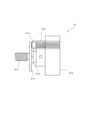
モータ30は、前述したファン20を駆動するための電気的駆動源であり、ファン20に対して手動で取り外し可能な螺合部材であるモータ取付用螺合部材31で取り付けられている。このため、特に工具を使用することなく、手動でモータ30をファン20に取り付けることができる。手動で取り外し可能なモータ取付用螺合部材31としては、螺合部材の頭に手で回すことが可能な大きさの把持部を有している蝶ボルト、つまみネジ、ノブボルト等が挙げられる。もちろんこれらに限定するものではない。このような手動で取り外し可能なモータ取付用螺合部材31でファン20とモータ30を取り付けることで、専門家でなくともファン20とモータ30を分離、組み立てをすることができる。さらに、手動で取り外し可能な螺合部材は、好ましくは、図4に示すように、ワッシャーやスプリングワッシャー等の座金31aがモータ取付用螺合部材31から外れないように加工してある。例えば、ボルトのねじ切りを行う前に座金31aに挿入した後に、ボルトのねじ切りを行うことで、座金31aが容易に抜けないようにすることができる。このようなモータ取付用螺合部材31を使用することで、モータ取付用螺合部材31を取り外した後に、座金31aがモータ取付用螺合部材31から外れて座金31aを紛失するという可能性を低減することができる。さらに、好ましくは、図5に示すように、締め不足及び締めすぎを防止することができるモータ取付用螺合部材31を使用するとよい。図5に示すモータ取付用螺合部材31は、把持部31bと、ネジ部31cと、把持部31bとネジ部31cとの間に、把持部31bの側からばね座金31d、溝付座金31fの順に取付けられている。把持部31bから溝付座金31fの近傍まで筒状に形成された筒状体31gが設けられており、内部にばね31iが挿入されており、その先端には、鉄等の金属からなる球体31hが設けられている。溝付座金31fは、図6に示すように、中心から放射状に凹溝31jが形成されている。こうして作製されたモータ取付用螺合部材31は、図7に示すように、ネジを締めていくと、溝付座金31fと把持部31bの間が狭くなり、溝付座金31fは、ファン26との摩擦で動かなくなる。この状態で把持部31bを回し続けると、球体31hが凹溝31jにはまり込みつつ溝付座金31fの表面を回転するように移動していくことになる。このときに、凹溝31jを移動する際にカチカチと音がなるので、音がなったら締め付けを完了する。これにより、モータ取付用螺合部材31の締め不足及び締めすぎを防止することができる。The
把持部材40は、ファン20又はモータ30に取り付けられる部材であり、ケーシング10の外部からモータ取付用螺合部材31で一体となったファン20及びモータ30を容易に手で保持することができるようにする部材である。本実施形態では、把持部材40は、中心に開口部41を有する円形の皿状に形成されており、周囲にモータ固定用孔42が設けられている。この開口部41にモータ30の一部を挿入して、モータ30のリブに形成されたボルト孔33を介してモータ固定用孔42にボルト81で固定されている。本実施形態においては、モータ30と把持部材40は、手で取り外せる螺合部材ではなく、工具によって取り外せる螺合部材を使用している。これは、モータ30はがたつきやすく、正確な位置にはめ込む必要があることと、モータ30そのものは汚れにくいことから、容易に取り外せない構造を採用したものである。もちろん、手で取り外せる螺合部材を使用することを排除するものではない。ファン20及びモータ30を取り付けた状態が図3に示されている。把持部材40には、取手43が把持部材40の皿形状の対向する側(左右端部)にそれぞれ設けられており、両手で把持部材40と一体となったファン20及びモータ30を保持することができる。把持部材40は、外周に複数の把持部材固定用孔44が設けられており、この把持部材固定用孔44を介して、手動で取り外し可能な把持部材固定用螺合部材46によって、ケーシング10に設けられた螺合孔15に固定することができる。そのため、ケーシング10へのファン20及びモータ30の取り付け及び取り外しともに、専門工具を必要とすることなく手動で行うことができる。把持部材固定用螺合部材46としては、螺合部材の頭に手で回すことが可能な大きさの把持部を有している蝶ボルト、つまみネジ、ノブボルト等が挙げられる。もちろんこれらに限定するものではない。また、排気用ファン装置100に精通していない者でもケーシング10に対してファン20及びモータ30を不適切な位置に固定することのないように、位置決めピン47が設けられている。一方、ケーシング10には、この位置決めピン47が挿入可能な位置決め孔17が設けられている。この位置決め孔17に合わせて位置決めピン47が挿入されるように把持部材40をはめ込むことによって、ファン20及びモータ30をケーシング10に対して適切な位置に取り付けることができる。なお、本実施形態では、取手43の取付用ボルトを兼ねており、取付用ボルトの頭が長細い円筒形のピンで形成されている。また、この位置決めピン47をケーシング10にはめ込むことによって差し込んだ状態でファン20、モータ30及び把持部材40をケーシング10に対して摩擦力によって落下することなく仮位置決めされる仮位置決め手段として機能し、ファン20、モータ30及び把持部材40から手を離した状態で把持部材固定用螺合部材46を回して固定することができる。このため、比較的重量があるファン20、モータ30及び把持部材40を支えながら固定する必要がないため、排気用ファン装置100に精通していない者が一人で取り外し、取り付けを容易に行うことができる。The gripping
カバー50は、ファン20、モータ30及び把持部材40を保護するための部材であり、ケーシング10に対して、ファン20、モータ30及び把持部材40を覆うようにして取り付けることができる。カバー50は必須なものではなく、なくても構わない。このカバー50を取り付ける取付部材も、手動で取り付け及び取り外しをすることができる螺合部材が使用される。そのため、専用工具を必要とすることなくカバー50を取り外し、組み立てることができる。The
接続部材60は、店舗の電源をモータ30に供給するための部材であり、モータ30の配線35に接続される。接続部材60は、店舗にある排気用ファン装置100用のブレーカーと接続されている。The
スイッチ70は、排気用ファン装置100への電源供給をオン/オフするスイッチである。通常は、排気用ファン装置100にはスイッチ70が設けられておらず、店舗内のブレーカーによって排気用ファン装置100の電源を切断するのが通常である。しかし、店舗用のブレーカーは数多くのブレーカーがあり、排気用ファン装置のブレーカーがどのブレーカーであるかわからない場合がある。また、そもそもブレーカーの場所が店内のどこにあるのかも知らない場合がある。しかし、本実施形態にかかる排気用ファン装置100によれば、排気ファン用電源のスイッチ70が排気用ファン装置100側に設けられているので、排気用ファン装置100を清掃する場合や分解する場合に、排気用ファン装置100側からスイッチ70をオン/オフすることができる。そのため、店内のブレーカーを切断することなく、排気ファン側でスイッチ70をオフにすることで店内のブレーカーを切断する必要がない。なお、スイッチ70は、排気用ファン装置100の取り付け位置によってスイッチ70の操作を使用しやすいように、スイッチ取り付け位置71は、図1のケーシング10の左上と右下の2箇所に取付可能となっている。もちろん、これ以外の位置に設けても構わない。The
以上のようにして作製された排気用ファン装置100は、以下のようにして使用される。まず、店舗外に設けられた排気用ファン装置100が汚れて清掃する場合は、カバー50を取り外す。これにより、スイッチ70を操作可能になるので、スイッチ70をオフにして排気用ファン装置100の電源を遮断する。モータ30が完全に止まったのを確認した後、把持部材固定用螺合部材46を手動で取り外す。これにより、ファン20、モータ30及び把持部材40が一体のままケーシング10から取り外すことができる。この際に把持部材40には取手43が設けられているので、両手でもって取り外すことができる。この状態でケーシング10は清掃することが可能である。ファン20、モータ30及び把持部材40は、必要であれば、モータ30からファン20を取り外し、ファン20を清掃する。このように、本発明にかかる排気用ファン装置100によれば、ケーシング10から最も汚れがひどくなるファン20を専用工具を必要とすることなく取り外すことができるので、排気用ファン装置100に精通していない者であっても容易に取り外して清掃することが可能となる。また、店内の電源システムを把握していない人であっても排気用ファン装置100側のスイッチ70で排気用ファン装置100の電源を切断することができるので、排気用ファン装置100の電源が切断されていないという状況になることを防止することができる。The
そして、清掃が完了した後は、ファン20をモータ30が取り付けられた把持部材40に把持部材固定用螺合部材46によって手動で取り付ける。この状態でケーシング10に対して位置決めピン47を位置決め孔17にはめ込むようにして取り付ける。この状態でファン20、モータ30及び把持部材40は、ケーシング10に対して仮位置決めの状態になり、位置決めピン47によって位置決め孔17で保持され、落下することなくケーシング10に保持される。よって、ファン20、モータ30及び把持部材40から手を離した状態で把持部材固定用螺合部材46をケーシング10に固定することができる。その後、スイッチ70をオンにしてカバー50を取り付けることで清掃が終了する。After cleaning is completed, the
上述した実施の形態で示すように、店舗用の排気用ファン装置として産業上利用することができる。As shown in the above embodiment, it can be used industrially as an exhaust fan device for stores.
110…ケーシング、11…吸引用孔、11a…ダクト取付具、12…取付用孔、13…排気用孔、13a…排気ダクト用取付具、15…螺合孔、17…位置決め孔、20…ファン、30…モータ、31…モータ取付用螺合部材、31a…座金、31b…把持部、31c…ネジ部、31d…座金、31f…溝付座金、31g…筒状体、31h…球体、31j…凹溝、32…リブ、33…ボルト孔、35…配線、40…把持部材、41…開口部、42…モータ固定用孔、43…取手、44…把持部材固定用孔、46…把持部材固定用螺合部材、47…ピン、50…カバー、60…接続部材、70…スイッチ、71…スイッチ取付け位置、81…ボルト、100…排気用ファン装置110... casing, 11... suction hole, 11a... duct mounting fixture, 12... mounting hole, 13... exhaust hole, 13a... exhaust duct mounting fixture, 15... screw hole, 17... positioning hole, 20... fan, 30... motor, 31... motor mounting screw member, 31a... washer, 31b... gripping portion, 31c... threaded portion, 31d... washer, 31f... grooved washer, 31g... cylindrical body, 31 h...sphere, 31j...groove, 32...rib, 33...bolt hole, 35...wiring, 40...gripping member, 41...opening, 42...motor fixing hole, 43...handle, 44...gripping member fixing hole, 46...gripping member fixing screw member, 47...pin, 50...cover, 60...connecting member, 70...switch, 71...switch mounting position, 81...bolt, 100...exhaust fan device
Claims (6)
Translated fromJapanese前記ケーシング内に配置されるファンと、
前記ファンに取り付けられるモータと、
前記ファン又は前記モータに取り付けられる取手を有する把持部材と、を備え、
前記ファンと前記モータは、手動で取付又は取外可能なモータ取付用螺合部材で固定されてなり、
前記把持部材と前記モータは、把持部材の周囲に設けられているモータ固定用孔とモータのリブに形成されたボルト孔を介して、手動で取り外し可能な螺合部材で固定されてなり、
前記把持部材と前記ケーシングは、手動で取付又は取外可能な把持部材固定用螺合部材で固定されていることを特徴とする排気用ファン装置。 A casing attached to a wall surface so that at least a portion of the casing is exposed to the outside;
A fan disposed within the casing;
a motor attached to the fan;
a gripping memberhaving a handle attached to the fan or the motor,
The fan and the motor are fixed to each other by a motor mounting screw member that can be manually attached or removed.
the gripping member and the motor are fixed to each other by a manually removable screw member through a motor fixing hole provided around the gripping member and a bolt hole formed in a rib of the motor;
13. An exhaust fan device according to claim 12, wherein said gripping member and said casing are fixed to each other by a screw member for fixing said gripping member which can be manually attached or detached.
前記把持部には、前記溝付座金の近傍まで筒状に形成された筒状体が設けられており、
前記筒状体の内部には、前記溝付座金側に球体が配置されたばねが挿入されていることを特徴とする請求項1から4のいずれか1項に記載の排気用ファン装置。 the motor mounting threaded member has a gripping portion, a threaded portion, and a grooved washer provided between the gripping portion and the threaded portion, the grooved washer having grooves formed radially from a center,
The gripping portion is provided with a cylindrical body that is formed in a cylindrical shape up to the vicinity of the grooved washer,
5. The exhaust fan device according to claim 1, wherein a spring having a sphere disposed on a side of the grooved washer is inserted inside the cylindrical body.
さらに、前記モータ、前記ファン及び前記把持部材を覆うことが可能なカバーを備えており、
前記カバーは、手動で取付又は取外可能な螺合部材で固定されていることを特徴とする排気用ファン装置。 The exhaust fan device according to any one of claims 1 to 5,
The present invention further includes a cover capable of covering the motor, the fan, and the gripping member,
11. An exhaust fan device according to claim 10, wherein the cover is fixed by a screw member that can be manually attached or removed.
Priority Applications (1)
| Application Number | Priority Date | Filing Date | Title |
|---|---|---|---|
| JP2024000778AJP7627975B2 (en) | 2019-11-20 | 2024-01-05 | Exhaust fan unit. |
Applications Claiming Priority (2)
| Application Number | Priority Date | Filing Date | Title |
|---|---|---|---|
| JP2019209880AJP7470959B2 (en) | 2019-11-20 | 2019-11-20 | Exhaust fan unit. |
| JP2024000778AJP7627975B2 (en) | 2019-11-20 | 2024-01-05 | Exhaust fan unit. |
Related Parent Applications (1)
| Application Number | Title | Priority Date | Filing Date |
|---|---|---|---|
| JP2019209880ADivisionJP7470959B2 (en) | 2019-11-20 | 2019-11-20 | Exhaust fan unit. |
Publications (2)
| Publication Number | Publication Date |
|---|---|
| JP2024028396A JP2024028396A (en) | 2024-03-04 |
| JP7627975B2true JP7627975B2 (en) | 2025-02-07 |
Family
ID=75964727
Family Applications (2)
| Application Number | Title | Priority Date | Filing Date |
|---|---|---|---|
| JP2019209880AActiveJP7470959B2 (en) | 2019-11-20 | 2019-11-20 | Exhaust fan unit. |
| JP2024000778AActiveJP7627975B2 (en) | 2019-11-20 | 2024-01-05 | Exhaust fan unit. |
Family Applications Before (1)
| Application Number | Title | Priority Date | Filing Date |
|---|---|---|---|
| JP2019209880AActiveJP7470959B2 (en) | 2019-11-20 | 2019-11-20 | Exhaust fan unit. |
Country Status (1)
| Country | Link |
|---|---|
| JP (2) | JP7470959B2 (en) |
Citations (3)
| Publication number | Priority date | Publication date | Assignee | Title |
|---|---|---|---|---|
| JP2012242071A (en) | 2011-05-24 | 2012-12-10 | Mitsubishi Electric Corp | Ventilation fan |
| CN105298928A (en) | 2014-06-29 | 2016-02-03 | 刘昕 | Warehouse air exchange unit with quick installation |
| JP2017036880A (en) | 2015-08-10 | 2017-02-16 | 株式会社ハーマン | Range hood |
Family Cites Families (4)
| Publication number | Priority date | Publication date | Assignee | Title |
|---|---|---|---|---|
| JPS5279747U (en)* | 1975-12-12 | 1977-06-14 | ||
| JPS5581637U (en)* | 1978-11-30 | 1980-06-05 | ||
| JPS5779323U (en)* | 1980-11-04 | 1982-05-17 | ||
| JPS5949116U (en)* | 1982-09-22 | 1984-04-02 | 松下精工株式会社 | Pressure ventilation fan |
- 2019
- 2019-11-20JPJP2019209880Apatent/JP7470959B2/enactiveActive
- 2024
- 2024-01-05JPJP2024000778Apatent/JP7627975B2/enactiveActive
Patent Citations (3)
| Publication number | Priority date | Publication date | Assignee | Title |
|---|---|---|---|---|
| JP2012242071A (en) | 2011-05-24 | 2012-12-10 | Mitsubishi Electric Corp | Ventilation fan |
| CN105298928A (en) | 2014-06-29 | 2016-02-03 | 刘昕 | Warehouse air exchange unit with quick installation |
| JP2017036880A (en) | 2015-08-10 | 2017-02-16 | 株式会社ハーマン | Range hood |
Also Published As
| Publication number | Publication date |
|---|---|
| JP2021081143A (en) | 2021-05-27 |
| JP2024028396A (en) | 2024-03-04 |
| JP7470959B2 (en) | 2024-04-19 |
Similar Documents
| Publication | Publication Date | Title |
|---|---|---|
| JP6622083B2 (en) | Air conditioner indoor unit | |
| US11054151B2 (en) | Indoor unit for air conditioner | |
| JP6749495B2 (en) | Indoor unit of fan and air conditioner equipped with fan | |
| EP1793126B1 (en) | Vibration damped electric fan | |
| JP7627975B2 (en) | Exhaust fan unit. | |
| JP5272351B2 (en) | Equipment | |
| US6881037B2 (en) | Two-piece safety mechanism for ceiling fans | |
| WO2020216101A1 (en) | Base and air conditioner | |
| JP2002106875A (en) | Motor mounting structure of air conditioner | |
| JP4735355B2 (en) | Air supply ventilation system | |
| JP2000081232A (en) | Ceiling-mounted air purifier | |
| JP3127400B1 (en) | Ceiling-mounted fan coil unit for easy internal cleaning | |
| KR200450750Y1 (en) | Duct frame fixing structure of air conditioner diffuser | |
| KR200225294Y1 (en) | Air conditioner | |
| US20050232776A1 (en) | Two-piece safety mechanism for ceiling fans | |
| CN219412972U (en) | Ceiling fan | |
| JP2005315552A (en) | Air supply / exhaust port and its construction method | |
| JPH11337137A (en) | Ceiling-mounted air cleaner | |
| JP3015656U (en) | Mounting structure of bell mouth in fan casing for multi-blade fan | |
| CN202391779U (en) | A quick detachable fan structure | |
| JPS5930814Y2 (en) | Ventilation fan fan motor mounting device | |
| JPH109627A (en) | Filter unit for ventilator | |
| KR200385804Y1 (en) | Grill construction structure for chamber of air diffuser device | |
| JPS6122208Y2 (en) | ||
| JP6920888B2 (en) | Ceiling-mounted electrical equipment with a blower |
Legal Events
| Date | Code | Title | Description |
|---|---|---|---|
| A621 | Written request for application examination | Free format text:JAPANESE INTERMEDIATE CODE: A621 Effective date:20240105 | |
| A977 | Report on retrieval | Free format text:JAPANESE INTERMEDIATE CODE: A971007 Effective date:20240618 | |
| A131 | Notification of reasons for refusal | Free format text:JAPANESE INTERMEDIATE CODE: A131 Effective date:20240702 | |
| A601 | Written request for extension of time | Free format text:JAPANESE INTERMEDIATE CODE: A601 Effective date:20240829 | |
| A521 | Request for written amendment filed | Free format text:JAPANESE INTERMEDIATE CODE: A523 Effective date:20241025 | |
| TRDD | Decision of grant or rejection written | ||
| A01 | Written decision to grant a patent or to grant a registration (utility model) | Free format text:JAPANESE INTERMEDIATE CODE: A01 Effective date:20250107 | |
| A61 | First payment of annual fees (during grant procedure) | Free format text:JAPANESE INTERMEDIATE CODE: A61 Effective date:20250121 | |
| R150 | Certificate of patent or registration of utility model | Ref document number:7627975 Country of ref document:JP Free format text:JAPANESE INTERMEDIATE CODE: R150 |