JP7626478B2 - Self-position estimation system for estimating the self-position of an unmanned aerial vehicle, flight control system, unmanned aerial vehicle, program, and recording medium - Google Patents
Self-position estimation system for estimating the self-position of an unmanned aerial vehicle, flight control system, unmanned aerial vehicle, program, and recording mediumDownload PDFInfo
- Publication number
- JP7626478B2 JP7626478B2JP2022574907AJP2022574907AJP7626478B2JP 7626478 B2JP7626478 B2JP 7626478B2JP 2022574907 AJP2022574907 AJP 2022574907AJP 2022574907 AJP2022574907 AJP 2022574907AJP 7626478 B2JP7626478 B2JP 7626478B2
- Authority
- JP
- Japan
- Prior art keywords
- aerial vehicle
- unmanned aerial
- longitudinal section
- cross
- self
- Prior art date
- Legal status (The legal status is an assumption and is not a legal conclusion. Google has not performed a legal analysis and makes no representation as to the accuracy of the status listed.)
- Active
Links
- RZVHIXYEVGDQDX-UHFFFAOYSA-N9,10-anthraquinoneChemical compoundC1=CC=C2C(=O)C3=CC=CC=C3C(=O)C2=C1RZVHIXYEVGDQDX-UHFFFAOYSA-N0.000titleclaimsdescription33
- 238000005259measurementMethods0.000claimsdescription101
- 230000003287optical effectEffects0.000claimsdescription35
- 238000000034methodMethods0.000claimsdescription26
- 238000003384imaging methodMethods0.000claimsdescription9
- 230000010365information processingEffects0.000description19
- 230000015654memoryEffects0.000description19
- 238000013500data storageMethods0.000description16
- 230000000007visual effectEffects0.000description16
- 238000004891communicationMethods0.000description14
- 238000010586diagramMethods0.000description12
- 230000006870functionEffects0.000description7
- 230000007274generation of a signal involved in cell-cell signalingEffects0.000description6
- 238000004364calculation methodMethods0.000description4
- 238000012545processingMethods0.000description4
- 238000005516engineering processMethods0.000description2
- 230000004807localizationEffects0.000description2
- WHXSMMKQMYFTQS-UHFFFAOYSA-NLithiumChemical compound[Li]WHXSMMKQMYFTQS-UHFFFAOYSA-N0.000description1
- HBBGRARXTFLTSG-UHFFFAOYSA-NLithium ionChemical compound[Li+]HBBGRARXTFLTSG-UHFFFAOYSA-N0.000description1
- 230000000694effectsEffects0.000description1
- 238000009499grossingMethods0.000description1
- 229910052744lithiumInorganic materials0.000description1
- 229910001416lithium ionInorganic materials0.000description1
- 238000013507mappingMethods0.000description1
- 239000002245particleSubstances0.000description1
- 229920000642polymerPolymers0.000description1
- 238000009423ventilationMethods0.000description1
Images


Classifications
- B—PERFORMING OPERATIONS; TRANSPORTING
- B64—AIRCRAFT; AVIATION; COSMONAUTICS
- B64C—AEROPLANES; HELICOPTERS
- B64C13/00—Control systems or transmitting systems for actuating flying-control surfaces, lift-increasing flaps, air brakes, or spoilers
- B64C13/02—Initiating means
- B64C13/16—Initiating means actuated automatically, e.g. responsive to gust detectors
- B64C13/18—Initiating means actuated automatically, e.g. responsive to gust detectors using automatic pilot
- G—PHYSICS
- G08—SIGNALLING
- G08G—TRAFFIC CONTROL SYSTEMS
- G08G5/00—Traffic control systems for aircraft
- B—PERFORMING OPERATIONS; TRANSPORTING
- B64—AIRCRAFT; AVIATION; COSMONAUTICS
- B64U—UNMANNED AERIAL VEHICLES [UAV]; EQUIPMENT THEREFOR
- B64U10/00—Type of UAV
- B64U10/10—Rotorcrafts
- B64U10/13—Flying platforms
- B64U10/16—Flying platforms with five or more distinct rotor axes, e.g. octocopters
- B—PERFORMING OPERATIONS; TRANSPORTING
- B64—AIRCRAFT; AVIATION; COSMONAUTICS
- B64U—UNMANNED AERIAL VEHICLES [UAV]; EQUIPMENT THEREFOR
- B64U2101/00—UAVs specially adapted for particular uses or applications
- B64U2101/30—UAVs specially adapted for particular uses or applications for imaging, photography or videography
- B—PERFORMING OPERATIONS; TRANSPORTING
- B64—AIRCRAFT; AVIATION; COSMONAUTICS
- B64U—UNMANNED AERIAL VEHICLES [UAV]; EQUIPMENT THEREFOR
- B64U30/00—Means for producing lift; Empennages; Arrangements thereof
- B64U30/20—Rotors; Rotor supports
- B—PERFORMING OPERATIONS; TRANSPORTING
- B64—AIRCRAFT; AVIATION; COSMONAUTICS
- B64U—UNMANNED AERIAL VEHICLES [UAV]; EQUIPMENT THEREFOR
- B64U60/00—Undercarriages
- B64U60/50—Undercarriages with landing legs
Landscapes
- Engineering & Computer Science (AREA)
- Aviation & Aerospace Engineering (AREA)
- Physics & Mathematics (AREA)
- General Physics & Mathematics (AREA)
- Automation & Control Theory (AREA)
- Control Of Position, Course, Altitude, Or Attitude Of Moving Bodies (AREA)
Description
Translated fromJapanese本発明は、無人航空機の自己位置を推定する自己位置推定システム、飛行制御システム、無人航空機、プログラム、及び、記録媒体に関する。The present invention relates to a self-position estimation system that estimates the self-position of an unmanned aerial vehicle, a flight control system, an unmanned aerial vehicle, a program, and a recording medium.
近時ドローンによるトンネルなどの構造物の点検が試みられている。ドローンは、GPSの衛星測位情報を利用して自己位置を推定し、飛行計画経路に沿って自律飛行することができるが、トンネルなどの構造物内の内部空間では、GPSによって正確な位置情報を得ることが難しい。そのため、そのような環境においては、Visual SLAMによる自己位置推定をGPSによる自己位置推定の代替とする技術が提案されている(下記非特許文献1)。ここで、Visual SLAMとは、連続して撮影された画像の複数のフレーム間で複数の特徴点を追跡することにより自己位置とマップの推定を並行して行う技術である。Recently, attempts have been made to use drones to inspect structures such as tunnels. Drones can estimate their own position using GPS satellite positioning information and fly autonomously along a flight plan route, but it is difficult to obtain accurate position information using GPS in the interior space of structures such as tunnels. Therefore, in such environments, a technology has been proposed that uses Visual SLAM to estimate their own position as an alternative to GPS-based self-position estimation (see Non-Patent
Visual SLAMによる自己位置推定においては、撮像した画像における特徴点を抽出し、その特徴点に基づき自己位置を推定する。しかしながら、トンネルなどの構造物の内壁には特徴点が少なく、Visual SLAMによる精度の高い自己位置推定は難しい。In self-location estimation using Visual SLAM, feature points are extracted from a captured image and the vehicle's self-location is estimated based on those feature points. However, there are few feature points on the inner walls of structures such as tunnels, making it difficult to achieve highly accurate self-location estimation using Visual SLAM.
そこで、本発明は、無人航空機がトンネルなどの特徴点の抽出が難しい内面を有する構造物の内部空間内の飛行を行う場合に、無人航空機の位置を推定するためのシステム及び方法を提供することを目的の1つとする。Therefore, one of the objectives of the present invention is to provide a system and method for estimating the position of an unmanned aerial vehicle when the unmanned aerial vehicle flies within the interior space of a structure, such as a tunnel, whose inner surface makes it difficult to extract feature points.
本発明の一態様は、無人航空機の自己位置を推定するための自己位置推定システムであって、無人航空機は、無人航空機の飛行経路を横切る方向の縦断面内の空間形状を測定し、縦断面測定データを生成する縦断面測定装置を含み、無人航空機が、横方向に所定の経路に沿って延びる構造物の内部空間を飛行するときに、縦断面測定装置により生成された縦断面測定データを取得する縦断面測定データ取得部と、縦断面測定データ取得部が取得した縦断面測定データに、構造物の内壁面に対応する第1の所定形状をマッチングし、マッチングした所定形状に対する自己位置に基づき、縦断面内における無人航空機の縦断面内位置を推定する縦断面内位置推定部と、を含む、自己位置推定システムを提供するものである。One aspect of the present invention provides a self-location estimation system for estimating the self-location of an unmanned aerial vehicle, the unmanned aerial vehicle including a longitudinal section measurement device that measures a spatial shape within a longitudinal section in a direction intersecting the flight path of the unmanned aerial vehicle and generates longitudinal section measurement data, a longitudinal section measurement data acquisition unit that acquires the longitudinal section measurement data generated by the longitudinal section measurement device when the unmanned aerial vehicle flies through the interior space of a structure extending laterally along a predetermined path, and a longitudinal section position estimation unit that matches the longitudinal section measurement data acquired by the longitudinal section measurement data acquisition unit with a first predetermined shape corresponding to the inner wall surface of the structure and estimates the position of the unmanned aerial vehicle within the longitudinal section based on the self-location relative to the matched predetermined shape.
本発明の一態様において、第1の所定形状は、少なくとも一部が幾何学的形状と対応しており、縦断面内位置推定部は、縦断面測定データに対して幾何学的形状をマッチングし、マッチングした幾何学的形状に対する自己位置に基づき、縦断面内位置を推定することができる。In one aspect of the present invention, the first predetermined shape corresponds at least in part to a geometric shape, and the longitudinal section position estimation unit can match the geometric shape to the longitudinal section measurement data and estimate the position within the longitudinal section based on the self-position relative to the matched geometric shape.
本発明の一態様において、幾何学的形状は、凸な曲線で構成される形状であることができる。In one aspect of the present invention, the geometric shape can be a shape composed of convex curves.
本発明の一態様において、幾何学的形状は、円形の一部又は全部、及び、楕円形の一部又は全部の少なくとも一つであることができる。In one aspect of the invention, the geometric shape may be at least one of a partial or complete circle and a partial or complete ellipse.
本発明の一態様において、縦断面内位置推定部は、縦断面測定データに対して構造物の底面に対応する第3の所定形状をマッチングし、マッチングした第3の所定形状に対して所定の高さ範囲に位置するように第1の所定形状をマッチングする。In one aspect of the present invention, the longitudinal section position estimation unit matches a third predetermined shape corresponding to the bottom surface of the structure to the longitudinal section measurement data, and matches the first predetermined shape so that it is located within a predetermined height range relative to the matched third predetermined shape.
本発明の一態様において、縦断面測定データは、離散データであり、縦断面内位置推定部は、離散データにおける外れ値を除去し、マッチングを行うことができる。In one aspect of the present invention, the longitudinal section measurement data is discrete data, and the longitudinal section position estimation unit can remove outliers in the discrete data and perform matching.
本発明の一態様において、無人航空機は、無人航空機の下方を撮像可能な撮像装置をさらに含み、無人航空機の飛行中に撮像装置により連続的に撮像された画像から無人航空機の横方向自己位置を推定する画像横方向位置推定部をさらに含むことができる。In one aspect of the present invention, the unmanned aerial vehicle may further include an imaging device capable of imaging an area below the unmanned aerial vehicle, and may further include an image lateral position estimation unit that estimates the lateral position of the unmanned aerial vehicle from images continuously captured by the imaging device while the unmanned aerial vehicle is flying.
本発明の一態様において、無人航空機は、無人航空機の所定の方向を基準とした横断面内の空間形状を測定し、横断面測定データを生成するための横断面測定装置をさらに含み、無人航空機が、横方向に所定の経路に沿って延びる構造物の内部空間を飛行するときに、横断面測定装置が生成した横断面測定データを取得する横断面測定データ取得部と、横断面測定データ取得部が取得した横断面測定データに第2の所定形状をマッチングし、マッチングした第2の所定形状に対する自己位置及び/又は姿勢に基づき、無人航空機の横断面内位置及び/又は姿勢を推定する光学断面内位置/姿勢推定部を含むことができる。In one aspect of the present invention, the unmanned aerial vehicle further includes a cross-section measuring device for measuring a spatial shape in a cross-section based on a predetermined direction of the unmanned aerial vehicle and generating cross-section measurement data, and may include a cross-section measurement data acquisition unit that acquires the cross-section measurement data generated by the cross-section measuring device when the unmanned aerial vehicle flies through the interior space of a structure extending laterally along a predetermined path, and an optical cross-sectional position/attitude estimation unit that matches a second predetermined shape to the cross-section measurement data acquired by the cross-section measurement data acquisition unit and estimates the position and/or attitude of the unmanned aerial vehicle in the cross-section based on its own position and/or attitude relative to the matched second predetermined shape.
本発明の一態様において、第2の所定形状は、少なくとも一部が線分状又は円弧状であることができる。In one aspect of the present invention, the second predetermined shape may be at least partially linear or arc-shaped.
本発明の一態様は、無人航空機の自己位置を推定するための自己位置推定システムであって、無人航空機は、無人航空機の所定の方向を基準とした横断面内の空間形状を測定し、横断面測定データを生成するための横断面測定装置を含み、無人航空機が、横方向に所定の経路に沿って延びる構造物の内部空間を飛行するときに、横断面測定装置が測定した横断面測定データを取得する横断面測定データ取得部と、横断面測定データ取得部が取得した横断面測定データに第2の所定形状をマッチングし、マッチングした第2の所定形状に対する自己位置及び/又は姿勢に基づき、無人航空機の横断面内位置及び/又は姿勢を推定する光学横断面内位置/姿勢推定部と、を含む、自己位置推定システムを提供する。One aspect of the present invention provides a self-location estimation system for estimating the self-location of an unmanned aerial vehicle, the unmanned aerial vehicle including a cross-section measurement device for measuring a spatial shape in a cross-section based on a predetermined direction of the unmanned aerial vehicle and generating cross-section measurement data, a cross-section measurement data acquisition unit for acquiring the cross-section measurement data measured by the cross-section measurement device when the unmanned aerial vehicle flies through the interior space of a structure extending laterally along a predetermined path, and an optical cross-section position/attitude estimation unit for matching the cross-section measurement data acquired by the cross-section measurement data acquisition unit with a second predetermined shape and estimating the cross-section position and/or attitude of the unmanned aerial vehicle based on the self-location and/or attitude relative to the matched second predetermined shape.
本発明の一態様は、第2の所定形状は、線分状であることができる。In one aspect of the present invention, the second predetermined shape may be a line segment.
本発明の一態様は、上記の自己位置推定システムと、自己位置推定システムにより推定された自己位置に基づき、設定された飛行計画経路に沿って無人航空機を飛行させる飛行制御部と、を含む、無人航空機の飛行制御システムを提供する。One aspect of the present invention provides a flight control system for an unmanned aircraft, including the self-location estimation system described above, and a flight control unit that flies the unmanned aircraft along a set flight plan route based on the self-location estimated by the self-location estimation system.
本発明の一態様は、上記の自己位置推定システムと、自己位置推定システムにより推定された横断面内位置及び/又は姿勢に基づき、設定された飛行計画経路に沿って無人航空機を飛行させる飛行制御部と、を含む、無人航空機の飛行制御システムを提供する。One aspect of the present invention provides a flight control system for an unmanned aircraft, including the above-mentioned self-localization estimation system and a flight control unit that flies the unmanned aircraft along a set flight plan route based on the in-transverse plane position and/or attitude estimated by the self-localization estimation system.
本発明の一態様は、上記の自己位置推定システムを有する、無人航空機を提供する。One aspect of the present invention provides an unmanned aerial vehicle having the above-described self-location estimation system.
本発明の一態様は、上記の飛行制御システムを有する、無人航空機を提供する。One aspect of the present invention provides an unmanned aerial vehicle having the above-described flight control system.
本発明の一態様は、無人航空機の自己位置をコンピュータにより推定する方法であって、無人航空機の飛行経路を横切る方向の縦断面内の空間形状を測定し、縦断面測定データを生成する縦断面測定装置から、無人航空機が横方向に所定の経路に沿って延びる構造物の内部空間を飛行するときに、縦断面測定データを取得する縦断面測定データ取得ステップと、縦断面測定データ取得ステップにおいて取得した縦断面測定データに、第1の所定形状をマッチングし、マッチングした所定形状に対する自己位置に基づき、縦断面内における無人航空機の縦断面内位置を推定する縦断面内位置推定ステップと、を含む、自己位置推定方法を提供する。One aspect of the present invention provides a method for estimating the self-position of an unmanned aerial vehicle using a computer, the method including: a longitudinal section measurement data acquisition step of acquiring longitudinal section measurement data from a longitudinal section measurement device that measures the spatial shape within a longitudinal section in a direction transverse to the flight path of the unmanned aerial vehicle and generates longitudinal section measurement data when the unmanned aerial vehicle flies through the interior space of a structure extending laterally along a predetermined path; and a longitudinal section position estimation step of matching a first predetermined shape to the longitudinal section measurement data acquired in the longitudinal section measurement data acquisition step, and estimating the position of the unmanned aerial vehicle within the longitudinal section within the longitudinal section based on the self-position relative to the matched predetermined shape.
本発明の一態様は、無人航空機の自己位置をコンピュータにより推定する方法であって、無人航空機の所定の方向を基準とした横断面内の空間形状を測定し、横断面測定データを生成する横断面測定装置から、無人航空機が、横方向に所定の経路に沿って延びる構造物の内部空間を飛行するときに、横断面測定データを取得する横断面測定データ取得ステップと、横断面測定データ取得ステップにおいて取得した横断面測定データに、第2の所定形状をマッチングし、マッチングした第2の所定形状に対する自己位置及び/又は姿勢に基づき、無人航空機の横方向位置及び/又は姿勢を推定する横断面内位置/姿勢推定ステップと、を含む、自己位置推定方法を提供する。One aspect of the present invention provides a method for estimating the self-position of an unmanned aerial vehicle using a computer, the method including: a cross-sectional measurement data acquisition step of acquiring cross-sectional measurement data from a cross-sectional measurement device that measures a spatial shape in a cross-section based on a predetermined direction of the unmanned aerial vehicle and generates cross-sectional measurement data when the unmanned aerial vehicle flies through the interior space of a structure extending laterally along a predetermined path; and a cross-sectional position/attitude estimation step of matching a second predetermined shape to the cross-sectional measurement data acquired in the cross-sectional measurement data acquisition step, and estimating the lateral position and/or attitude of the unmanned aerial vehicle based on its self-position and/or attitude relative to the matched second predetermined shape.
本発明の一態様は、上記の方法をコンピュータに実行させるためのプログラムを提供する。One aspect of the present invention provides a program for causing a computer to execute the above method.
本発明の一態様は、上記のプログラムを記録したコンピュータ読み取り可能な記録媒体を提供する。One aspect of the present invention provides a computer-readable recording medium having the above-mentioned program recorded thereon.
本発明によれば、本発明は、無人航空機がトンネルなどの構造物の内部空間内の自律飛行を行う場合に、無人航空機の位置を推定するためのシステム及び方法を提供することができる。According to the present invention, the present invention can provide a system and method for estimating the position of an unmanned aerial vehicle when the unmanned aerial vehicle is flying autonomously within the interior space of a structure such as a tunnel.
以下、本発明の実施形態について図面を参照して説明する。ただし、本発明は以下に説明する具体的態様に限定されるわけではなく、本発明の技術思想の範囲内で種々の態様を取り得る。例えば、本発明の無人航空機は、図1に示すマルチコプタに限らず、回転翼機、固定翼機等、任意の無人航空機であってもよい。また、無人航空機1のシステム構成も、図に示されるものに限らず同様の動作が可能であれば任意の構成を取ることができる。例えば通信回路の機能を飛行制御部に統合する等、複数の構成要素が実行する動作を単独の構成要素により実行してもよいし、あるいは主演算部の機能を複数の演算部に分散する等、単独の構成要素が実行する動作を複数の構成要素により実行してもよい。また、無人航空機1のメモリ内に記憶される各種データは、それとは別の場所に記憶されていてもよいし、各種メモリに記録される情報も、1種類の情報を複数の種類に分散して記憶してもよいし、複数の種類の情報を1種類にまとめて記憶してもよい。The following describes an embodiment of the present invention with reference to the drawings. However, the present invention is not limited to the specific aspects described below, and various aspects can be taken within the scope of the technical concept of the present invention. For example, the unmanned aerial vehicle of the present invention is not limited to the multicopter shown in FIG. 1, but may be any unmanned aerial vehicle such as a rotorcraft or fixed-wing aircraft. The system configuration of the unmanned
以下の説明では、水平方向に延びるトンネル内を無人航空機により自律飛行し、トンネルの内壁面について撮像する場合について説明する。トンネルの形状については、設計図などにより既知であり、本実施形態では、トンネル内の内部空間が、垂直断面(縦断面)における内面形状が半円状であり、同断面で水平方向(横方向)に延びるような形状である。The following explanation describes a case where an unmanned aerial vehicle autonomously flies inside a horizontally extending tunnel and captures images of the tunnel's inner wall surface. The shape of the tunnel is known from blueprints, etc., and in this embodiment, the internal space within the tunnel has a semicircular inner shape in a vertical cross section (longitudinal cross section) and extends horizontally (laterally) on the same cross section.
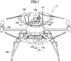
図1は、本発明の一実施形態に係る無人航空機(マルチコプタ)1の一例であるマルチコプタの外観図である。無人航空機1は、外観に関しては、制御ユニット101と、制御ユニット101からの制御信号により駆動される6つのモータ102と、各々のモータ102の駆動により回転して揚力を発生させる6つのロータ(回転翼)103と、制御ユニット101と各々のモータ102とを接続する6つのアーム104と、着陸時に無人航空機を支える着陸脚105とを備える。モータ102、ロータ103、及びアーム104の数は、それぞれ、3、4などのような3以上の数とすることもできる。制御ユニット101からの制御信号により6つのモータ102が回転させられ、それにより6つのロータ103の各々の回転数を制御することにより、上昇、下降、前後左右への飛行、旋回等、無人航空機1の飛行が制御される。1 is an external view of a multicopter, which is an example of an unmanned aerial vehicle (multicopter) 1 according to an embodiment of the present invention. With regard to the external appearance, the unmanned
また、制御ユニット101の上方には台座106が取り付けられている。そして、高解像度で対象物を撮影するための第1のカメラ108が、第1のカメラ108を回転可能に支持する支持部材107を介して台座106に取り付けられている。In addition, a
また、台座106の前方には水平断面(横断面)について周辺空間の形状を測定するための横断面測定装置(水平断面LIDAR)111が設けられている。横断面測定装置111は、本実施形態では、水平断面LIDARであり、無人航空機1が着地又はホバリングしている状態で水平面内において、鉛直軸周りに全周にわたって所定の角度間隔でパルスレーザを照射し、周辺空間の物体に当たって反射されたレーザを受光することにより、照射から受光までの時間に基づき周辺空間の物体までの距離を測定することができる。トンネル内で無人航空機1が飛行した状態で横断面測定装置111を駆動することにより、横断面測定装置111は、トンネルの内壁面(トンネル内部空間の形状)の水平断面形状(横断面形状)に関する横断面測定データを生成する。横断面測定データとしては、例えば、無人航空機の前方を基準とした極座標の離散データである。なお、本実施形態では、横断面測定装置111として、水平断面LIDARを用いているが、本発明はこれに限定されない。例えば、無人航空機を中心として横断面全周を可視光カメラにより撮像し、撮像した画像を統合し、3Dモデルを作成することにより、横断面内のトンネルの内壁面の形状を測定するとともに、横断面内の自己位置を推定することができる。このような3Dモデルを作成するためのアルゴリズムとしては、SfMが知られており、また、SfMを使用して自己位置を推定するアルゴリズムとしてはDense Visual SLAMが知られている。In addition, a cross-section measuring device (horizontal section LIDAR) 111 for measuring the shape of the surrounding space in a horizontal section (cross section) is provided in front of the
また、制御ユニット101の下方には架台110が取り付けられている。そして、架台110の下方には、前方には後述のVisual SLAM処理を行うための対象物の画像を撮影するための第2のカメラ(撮像装置)109が下方に向けて取り付けられている。A
また、架台110の前方には中心軸に垂直な垂直断面について周辺空間の形状を測定するための縦断面測定装置(垂直断面LIDAR)112が設けられている。縦断面測定装置112は、本実施形態では、垂直断面LIDARであり、無人航空機1が着地又はホバリングしている状態で、無人航空機1の前後方向に鉛直な断面内において、前後方向に延びる水平軸周りに全周にわたって所定の角度間隔でパルスレーザを照射し、周辺空間の物体に当たって反射されたレーザを受光することにより、照射から受信までの時間に基づき周辺空間の物体までの距離を測定する。トンネル内で無人航空機1が飛行した状態で縦断面測定装置112を駆動することにより、縦断面測定装置112は、トンネルの内壁面の鉛直断面形状(縦断面形状)に関する縦断面測定データを生成する。縦断面測定データとしては、例えば、極座標の離散データが得られる。なお、本実施形態では、縦断面測定装置112として、垂直断面LIDARを用いているが本発明はこれに限定されない。例えば、無人航空機を中心として縦断面全周を可視光カメラにより撮像し、撮像した画像を統合し、3Dモデルを作成することにより、縦断面内のトンネルの内壁面の形状を測定するとともに、縦断面内の自己位置を推定することができる。このような3Dモデルを作成するためのアルゴリズムとしては、SfMが知られており、また、SfMを使用して自己位置を推定するアルゴリズムとしてはDense Visual SLAMが知られている。 また、無人航空機1は、アンテナ117も有している。In addition, a vertical section measuring device (vertical section LIDAR) 112 for measuring the shape of the surrounding space in a vertical section perpendicular to the central axis is provided in front of the
図2は、図1に示す無人航空機の飛行制御システムを示す図である。無人航空機1の飛行制御システム200は、制御ユニット101、制御ユニット101に電気的に接続されたモータ102、モータ102に機械的に接続されたロータ103、第1のカメラ108、第2のカメラ109、縦断面測定装置112、及び、横断面測定装置111を有する。Figure 2 is a diagram showing the flight control system of the unmanned aerial vehicle shown in Figure 1. The
制御ユニット101は、無人航空機1の飛行制御を行うための情報処理や、そのための電気信号の制御を行うための構成であり、典型的には基板上に各種の電子部品を配置して配線することによってそのような機能の実現に必要な回路を構成したユニットである。制御ユニット101は、さらに、情報処理ユニット120、通信回路121、制御信号生成部122、スピードコントローラ123、インターフェイス125から構成される。The
第1のカメラ108は、高解像度で対象物(本実施形態では、トンネルの内壁)を撮像するためのカメラである。第1のカメラ108は、第1のカメラ108を回転可能に支持する支持部材107を介して台座106に取り付けられていて、これにより撮像方向を変えることができるようになっている。第1のカメラ108は、無人航空機1の飛行中、それの撮影範囲の画像のデータを取得し、取得された画像は、後述のメモリなどの記憶装置に記憶される。画像は、典型的には一連の静止画像からなる動画の画像である。The
第2のカメラ109は、後述のVisual SLAM処理を行うための対象物の画像を撮影するためのカメラであり、架台110に下方を向くように取り付けられている。Visual SLAM処理の負荷を低減するために、低解像度での撮像を行う第2のカメラ109が、第1のカメラ108とは別個に設けられている。第2のカメラ109は、無人航空機1の飛行中、それの撮影範囲の画像のデータを取得する。撮影範囲は、連続するように設定されえている。取得された画像は、情報処理ユニット120のメモリに記憶される。画像は、典型的には一連の静止画像からなる動画の画像である。The
アンテナ117は、無人航空機1を操縦したり制御するための情報や各種データを含む無線信号を受信したり、テレメトリ信号を含む無線信号を無人航空機1から送信するための空中線である。
通信回路121は、アンテナ117を通じて受信した無線信号から、無人航空機1のための操縦信号、制御信号や各種データなどを復調して情報処理ユニット120に入力したり、無人航空機1から出力されるテレメトリ信号などを搬送する無線信号を生成するための電子回路であり、典型的には無線信号処理ICである。なお、例えば、操縦信号の通信と、制御信号、各種データの通信とを別の周波数帯の異なる通信回路で実行するようにしてもよい。例えば、手動での操縦を行うためのコントローラ(プロポ)の送信器と950MHz帯の周波数で通信し、データ通信を2GHz帯/1.7GHz帯/1.5GHz帯/800MHz帯の周波数で通信するような構成を採ることも可能である。The
制御信号生成部122は、情報処理ユニット120によって演算により得られた制御指令値データを、電圧を表わすパルス信号(PWM信号など)に変換する構成であり、典型的には、発振回路とスイッチング回路を含むICである。スピードコントローラ123は、制御信号生成部122からのパルス信号を、モータ102を駆動する駆動電圧に変換する構成であり、典型的には、平滑回路とアナログ増幅器である。図示していないが、無人航空機1は、リチウムポリマーバッテリやリチウムイオンバッテリ等のバッテリデバイスや各要素への配電系を含む電源系を備えている。The control
インターフェイス125は、情報処理ユニット120と第1のカメラ108、第2のカメラ109、縦断面測定装置112、及び横断面測定装置111などの機能要素との間で信号の送受信ができるように信号の形態を変換することにより、それらを電気的に接続する構成である。なお、説明の都合上、図面においてインターフェイスは1つの構成として記載しているが、接続対象の機能要素の種類によって別のインターフェイスを使用することが通常である。また、接続対象の機能要素が入出力する信号の種類によってはインターフェイス125が不要な場合もある。また、図2において、インターフェイス125が媒介せずに接続されている情報処理ユニット120であっても、接続対象の機能要素が入出力する信号の種類によってはインターフェイスが必要となる場合もある。The
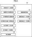
図3は、図1に示す無人航空機の情報処理ユニットの構成を示すブロック図である。図3に示すように、情報処理ユニット120は、断面形状データ記憶部130と、飛行経路データ記憶部131と、画像横方向位置推定部132と、光学縦断面内位置推定部133と、光学横断面内位置/姿勢推定部134と、自己位置データ生成部135と、飛行制御部136と、撮像画像取得部137と、縦断面測定データ取得部138と、横断面測定データ取得部139と、を含む。本実施形態では、断面形状データ記憶部130と、画像横方向位置推定部132と、光学縦断面内位置推定部133と、光学横断面内位置/姿勢推定部134と、自己位置データ生成部135と、撮像画像取得部137と、縦断面測定データ取得部138と、横断面測定データ取得部139と、により無人航空機の自己位置に関する自己位置データを生成する自己位置推定システム140が構成される。Figure 3 is a block diagram showing the configuration of the information processing unit of the unmanned aerial vehicle shown in Figure 1. As shown in Figure 3, the
図4は、図1に示す無人航空機の情報処理ユニットのハードウェア構成を示す図である。情報処理ユニット120は、CPU120aと、RAM120bと、ROM120cと、外部メモリ120dと、入力部120eと、出力部120fと、通信部120gとを含む。RAM120b、ROM120c、外部メモリ120d、入力部120e、出力部120f、及び、通信部120gはバス120hを介してCPU120aに接続されている。Figure 4 is a diagram showing the hardware configuration of the information processing unit of the unmanned aerial vehicle shown in Figure 1. The
CPU120aは、システムバス120hに接続される各デバイスを統括的に制御する。
ROM120cや外部メモリには、CPU120aの制御プログラムであるBIOSやOS、コンピュータが実行する機能を実現するために必要な各種プログラムやデータ等が記憶されている。 The
The
RAM120bは、CPU120aの主メモリや作業領域等として機能する。CPU120aは、処理の実行に際して必要なプログラム等をROM120cや外部メモリ120dからRAM120bにロードして、ロードしたプログラムを実行することで各種動作を実現する。
外部メモリ120dは、例えば、フラッシュメモリ、ハードディスク、DVD-RAM、USBメモリ等から構成される。 The
The
入力部120eは、ユーザ等から操作指示等を受け付ける。入力部120eは、例えば、入力ボタン、キーボード、ポインティングデバイス、ワイヤレスリモコン、マイクロフォン、カメラ等の入力デバイスから構成される。The
出力部120fは、CPU120aで処理されるデータや、RAM120b、ROM120cや外部メモリ120dに記憶されるデータを出力する。出力部120fは、例えば、CRTディスプレイ、LCD、有機ELパネル、プリンタ、スピーカ当の出力デバイスから構成される。The
通信部120gは、ネットワークを介して、又は、直接外部機器と接続・通信するためのインターフェイスである。通信部120gは、例えば、シリアルインタフェース、LANインターフェイス等のインターフェイスから構成される。The
図2、3に示される飛行制御システム及び位置推定システムの各部121、122、125、130~139は、ROM120cや外部メモリ120dに記憶された各種プログラムが、CPU120a、RAM120b、ROM120c、外部メモリ120d、入力部120e、出力部120f、通信部120g等を資源として使用することで実現される。The
断面形状データ記憶部130は、トンネルの内壁面の断面騎乗に関する断面形状データを記憶する。また、飛行経路データ記憶部131は、飛行計画経路データを記憶する。断面形状データ記憶部130及び飛行経路データ記憶部131は、ROM120cや外部メモリ120dなどの記録媒体に記録されたデータを読み取り、メモリが記憶することにより実現される。なお、断面形状データ記憶部130及び飛行経路データ記憶部131は、断面形状データ及び飛行計画経路データをプログラムに組み込むことにより省略することも可能である。The cross-sectional shape
本実施形態では、情報処理ユニット120を自己位置推定システム及び飛行制御システムとして機能させているが、情報処理ユニット120とは別個にこれらシステムを搭載する等して無人航空機に備えられる構成としてもよい。また、自己位置推定システム及び飛行制御システム又はその構成要素は、1つの物理的な装置として構成される必要はなく、複数の物理的な装置から構成されてもよい。また、自己位置推定システム及び飛行制御システムを、無人航空機とは別体の地上局のコンピュータ、PC、スマートフォン、タブレット端末等の任意の適切な装置、クラウド・コンピューティングシステム、又はそれらの組み合わせ等として構成してもよい。また、自己位置推定システム及び飛行制御システムの各部の機能は、無人航空機が備える1つ又は複数の装置及び無人航空機とは別体の1つ又は複数の装置のうちのいずれか1つで又は複数で分散して実行される構成としてもよい。In this embodiment, the
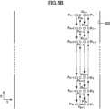
図5A~図5Cは、本発明の一実施形態におけるトンネル及び飛行計画経路を示し、図5Aはトンネル幅方向の鉛直断面図であり、図5Bは上面図、図5Cは図5AにおけるC-C断面図である。図5A~図5Cに示すように、本実施形態では、トンネルの内面の縦断面は半円形であり、同断面形状で直線状に延びている。Figures 5A to 5C show a tunnel and a flight plan route in one embodiment of the present invention, where Figure 5A is a vertical cross-sectional view in the tunnel width direction, Figure 5B is a top view, and Figure 5C is a cross-sectional view taken along line C-C in Figure 5A. As shown in Figures 5A to 5C, in this embodiment, the longitudinal cross-section of the inner surface of the tunnel is semicircular, and extends linearly with the same cross-sectional shape.
このため、既知のトンネルの内壁面302の形状を示す断面形状データは、例えば、トンネルの内壁面302に対応する、Z2+Y2=R2(Z>0)で示される半円(中心座標(Y=0、Z=0)、かつ、半径R)と、トンネル底面304に対応する、Z=0(-R≦Y≦R)で表される線分(高さZ=0及び傾き0)を含んでいる。なお、トンネルの内壁面の形状は、奥行き方向(X方向)によらず一定であるため、Xは上記式には存在しない。本実施形態では、断面形状データは、トンネルの内壁面に対応する第1の幾何学的形状として、円(半円)を示すデータを含んでいるが、これに限らず、トンネルの断面形状に応じて、楕円形などの凸な曲線で構成される形状や、長方形等を示すデータを含んでもよい。また、半円を表すデータは、半径Rや中心座標を含んでいるが、円形であるという情報のみであってもよい。また、線分を表すデータは高さ及び傾きを含んでいるが、線分であるという情報のみであってもよい。なお、ここでいう幾何学的形状は、例えば、X座標、Y座標、Z座標に関する数式により特定することができる形状をいう。なお、断面形状データは、必ずしもトンネルの内壁面の半円の半径を含んでいる必要はなく、また、底面を示す線分に関する情報を含んでいなくてもよい。半円の半径に関する値や、底面に関するデータを含んでいない場合であっても、一部に円形が含まれているという情報が断面形状データに反映されていれば、円によるマッチングを行うことは可能である。さらに、断面形状データは、奥行き方向(X方向)の形状についても含んでいる必要はない。後述するように、トンネルの奥行き方向の断面形状が不明であっても、壁面に沿った自律飛行は可能である。 For this reason, the cross-sectional shape data indicating the shape of the
飛行計画経路データは、無人航空機1の三次元(X、Y、Z)の飛行計画経路を表すデータであり、典型的には、飛行計画経路上に存在する一連の複数のウェイポイントP1~P4nの集合のデータである。各ウェイポイントP1~P4nは、三次元座標(X、Y、Z)で設定されている。飛行計画経路は、典型的には、それらの複数のウェイポイントを順番に結んだ直線の集合であるが、ウェイポイントの所定範囲内においては所定の曲率の曲線とすることもできる。飛行計画経路データは、複数のウェイポイントにおける飛行速度を定めるデータを含んでいてもよい。飛行計画経路データは、典型的には自律飛行において飛行計画経路を定めるために使用されるが、非自律飛行において飛行時のガイド用として使用することもできる。飛行計画経路データは、典型的には、飛行前に無人航空機1に入力されて記憶される。 The flight plan route data is data representing a three-dimensional (X, Y, Z) flight plan route of the unmanned
なお、本実施形態におけるX座標は、必ずしも直線上の座標に限定されない。すなわち、X座標としては、始点からトンネルの奥行方向に向かうトンネルの経路に沿うような経路における距離としてもよい。In this embodiment, the X coordinate is not necessarily limited to a coordinate on a straight line. In other words, the X coordinate may be the distance along a path of the tunnel from the starting point toward the depth of the tunnel.
本実施形態では、図5A~図5Cに示すように、飛行計画経路は、以下の通り設定されている。
-垂直断面(YZ断面)において所定の位置でトンネルの延びる方向(X方向)に奥に向かって所定の距離移動(ウェイポイントP1~Pn)、
-垂直断面(YZ断面)内をトンネルの中心と同心円上を図4Aにおける反時計回りに所定の角度移動(ウェイポイントPn~Pn+1)、
-垂直断面(YZ断面)において所定の位置でトンネルの延びる方向(X方向)に手間に向かって所定の距離移動(ウェイポイントPn+1~P2n)、
-垂直断面(YZ断面)内をトンネルの中心と同心円上を図4Aにおける反時計回りに所定の角度移動(ウェイポイントP2n~P2n+1)、
-垂直断面(YZ断面)において所定の位置でトンネルの延びる方向(X方向)に奥に向かって所定の距離移動(ウェイポイントP2n+1~P3n)、
-垂直断面(YZ断面)内をトンネルの中心と同心円上を図4Aにおける反時計回りに所定の角度移動(ウェイポイントP3n~P3n+1)、
-垂直断面(YZ断面)において所定の位置でトンネルの延びる方向(X方向)に手前に向かって所定の距離移動(ウェイポイントP3n+1~P4n)
各ウェイポイントP1~P4nは、第1のカメラ108によりトンネル内壁面を撮影する位置が設定されている。 In this embodiment, as shown in FIGS. 5A to 5C, the flight plan route is set as follows:
- Move a predetermined distance toward the back in the tunnel extension direction (X direction) at a predetermined position on the vertical cross section (YZ cross section) (waypoints P1 to Pn ),
- Move a predetermined angle counterclockwise in FIG. 4A on a circle concentric with the center of the tunnel in the vertical section (YZ section) (waypoints Pn to Pn+1 ),
- Move a predetermined distance toward the target in the direction of the tunnel extension (X direction) at a predetermined position on the vertical cross section (YZ cross section) (waypoints Pn+1 to P2n ),
- Move a predetermined angle counterclockwise in FIG. 4A on a circle concentric with the center of the tunnel in the vertical cross section (YZ cross section) (waypoints P2n to P2n+1 ),
- Move a predetermined distance toward the back in the direction in which the tunnel extends (X direction) at a predetermined position on the vertical cross section (YZ cross section) (way points P2n+1 to P3n ),
- Move a predetermined angle counterclockwise in FIG. 4A on a circle concentric with the center of the tunnel within the vertical cross section (YZ cross section) (waypoints P3n to P3n+1 ),
- Move a predetermined distance toward the front in the direction in which the tunnel extends (X direction) at a predetermined position on the vertical cross section (YZ cross section) (way points P3n+1 to P4n )
Each of the waypoints P1 to P4n is set as a position where the
撮像画像取得部137は、第1のカメラ108を制御可能であり、第1のカメラ108により連続的に撮像された画像を取得する。
画像横方向位置推定部132は、撮像画像取得部137により取得された画像に基づき、横方向位置(XA,YA)を推定する。このような画像横方向位置推定部132としては、マップ作成及び自己位置推定を行うVSLAM(Visual SLAM)が広く知られている。Visual SLAMについては、MonoSLAMやPTAM(Parallel Tracking and Mapping等、さまざまなアルゴリズムが開発されている。画像横方向位置推定部132は、記録媒体に記録されたVisual SLAMなどを実装したプログラムを実行することにより実現される。なお、第2のカメラ109としては単眼カメラではなく、ステレオカメラを用いてもよく、この場合も同様の原理でVisual SLAMによる自己位置等の推定が可能である。 The captured
The image lateral
縦断面測定データ取得部138は、縦断面測定装置112を制御可能であり、縦断面測定装置112により取得された縦断面測定データを取得する。光学縦断面内位置推定部133は、縦断面測定データ取得部138により取得された縦断面測定データと、断面形状データ記憶部130に記録された断面形状データとに基づき、縦断面内における無人航空機の縦断面内位置A(YB、ZB)を推定する。図6は、縦断面内における無人航空機の縦断面内位置を推定する方法を説明するための図である。図6に示すように、縦断面測定データは、無人航空機の縦断面測定装置112の位置に対して極座標で表される点Q1~Qn(図6に示す例では、n=16)からなる。本実施形態では、光学縦断面内位置推定部133は、トンネル底面に対応する第3の所定形状、本実施形態では直線(線分)、をマッチングし、この直線から所定の高さ範囲内に中心が位置するように、トンネル内壁面に対応する第1の所定形状、本実施形態では円(半円)、をマッチングする。なお、円(半円)をマッチングするとは、一部に円形をマッチングするのみならず、当然円弧をマッチングするような場合も含む。 The longitudinal section measurement
具体的には、まず、点Q1~Qnに対して直線をマッチングする。直線マッチングのアルゴリズムとしては、最小二乗法や、RANSACなどを作用することができるが、本実施形態では、外れ値を除外してマッチングを行うRANSACなどのアルゴリズムが適している。RANSACにより直線をマッチングする際には、以下のように行う。
ステップ1.まず、離散点Q1~Q16からランダムに2点(又はそれ以上の点)を選択する。
ステップ2.ステップ1で決定した2点を通る暫定の直線モデルを導出する。なお、ステップ1で3点以上を選択した場合には最小二乗法などで決定すればよい。
ステップ3.得られた直線モデルと、離散点Q1~Q16との誤差を求める。誤差が所定値よりも小さい場合には、「正しいモデル候補」に加える。
ステップ4.ステップ1~3を繰り返す。
ステップ5.正しいモデル候補の中で最もデータに合致するものを直線マッチングの結果として採用する。 Specifically, first, a straight line is matched to the points Q1 to Qn. As an algorithm for straight line matching, the least squares method, RANSAC, etc. can be used, but in this embodiment, an algorithm such as RANSAC that performs matching while excluding outliers is suitable. When matching a straight line using RANSAC, the following procedure is performed.
Step 4. Repeat steps 1-3.
Step 5. The candidate correct model that best fits the data is taken as the result of line matching.
なお、本実施形態では、外れ値を除外してマッチングを行うアルゴリズムとしてRANSACを使用するが、Markov Localization、Monte-Carlo Localization、Particle Filter、Hough Transformなどを使用することも可能である。In this embodiment, RANSAC is used as an algorithm to remove outliers and perform matching, but it is also possible to use Markov Localization, Monte-Carlo Localization, Particle Filter, Hough Transform, etc.
例えば、図6に示す例において、Q15は、トンネル底面に対応する離散点の中で他の離散点の傾向から大きく離れている。ステップ1で、Q13とQ15を選択すると直線モデルはL1となる。これに対して、ステップ1で、Q12Q16を選択すると直線モデルはL2となる。このような直線モデルL1及びL2とQ11~Q16の誤差を求めると、直線モデルL1の誤差は、直線モデルL2の誤差よりも大きくなる。このため、ステップ5において、直線モデルL1を設定する際に用いたQ15などの他のデータの傾向から外れた値は、直線を決定するためのデータとしては用いず、直線モデルL2のような外れ値の影響を除去した直線がマッチングされる。また、同様に、ステップ1においてトンネルの底面以外に対応する点Q1~Q10を選択したとしても、暫定の直線モデルの傾きが非常に大きくなり、ステップ3において「正しいモデル候補」とはならない。For example, in the example shown in FIG. 6, Q15 is far from the trend of the other discrete points among the discrete points corresponding to the tunnel bottom. If Q13 and Q15 are selected in
なお、本実施形態では、トンネル底面を示す断面形状データは、傾きや高さに関するデータを含んでいるが、この傾きをステップ3における「正しいモデル候補」の選別に使用することもできる。具体的には、例えば、直線モデルの傾きや高さと、断面形状データの傾きや高さとの差が所定値以上である場合には「正しいモデル候補」としなければよい。In this embodiment, the cross-sectional shape data showing the tunnel bottom includes data on the slope and height, and this slope can also be used to select the "correct model candidate" in
次に、点Q1~Qnに対して円をマッチングする。円マッチングのアルゴリズムとしても、最小二乗法や、RANSACなどを作用することができるが、直線マッチングと同様に、外れ値を除外してマッチングを行うRANSACが適している。RANSACにより円をマッチングする際には、以下のように行う。
ステップ0.離散点Q1~Q16のうち、上記マッチングした直線モデルL2よりも下方の点を候補から除外する。
ステップ1.ステップ0で残った離散点Q1~Q16からランダムに3点を選択する。
ステップ2.ステップ1で決定した3点を通る暫定の円モデルを導出する。
ステップ3.得られた円モデルと、離散点Q1~Q16との誤差を求める。誤差が所定値よりも小さい場合には、「正しいモデル候補」に加える。
ステップ4.ステップ1~3を繰り返す。
ステップ5.正しいモデル候補の中で最もデータに合致するものを円マッチングの結果として採用する。 Next, a circle is matched to the points Q1 to Qn. The least squares method, RANSAC, etc. can be used as an algorithm for circle matching, but RANSAC, which performs matching by excluding outliers, is suitable, as in the case of line matching. When matching a circle using RANSAC, the following procedure is performed.
Step 0. Among the discrete points Q1 to Q16, the points below the matched straight line model L2 are excluded from the candidates.
Step 4. Repeat steps 1-3.
Step 5. The candidate correct model that best matches the data is taken as the result of circle matching.
例えば、図5に示す例において、Q3は、トンネル底面に対応する離散点の中で他の離散点の傾向から大きく離れている。そして、図5に示す例において、ステップ1で、Q3とQ4とQ5を選択すると円モデルはC1となる。これに対して、ステップ1で、Q1と、Q4と、Q8を選択すると円モデルはC2となる。このような円モデルC1及びC2とQ1~Q16の誤差を求めると、円モデルC1の誤差は、円モデルC2の誤差よりも大きくなる。このため、ステップ5において、円モデルC1を設定する際に用いたQ3などの他のデータの傾向から外れた値は、円を決定するためのデータとしては用いず、円モデルC2のような外れ値の影響を除去した円がマッチングされる。For example, in the example shown in Figure 5, Q3 is significantly different from the trends of the other discrete points among the discrete points corresponding to the tunnel bottom. In the example shown in Figure 5, if Q3, Q4, and Q5 are selected in
なお、本実施形態では、ステップ0において、直線モデルL2よりも下方の点を候補から除外しているが、これに限らず、例えば、ステップ2において導出した暫定の円モデルの中心が所定の高さの範囲に入らないものをステップ3において「正しいモデル候補」から除外してもよい。すなわち、本実施形態でいえば、ステップ2において導出した暫定の円モデルの中心の高さZが所定の範囲外(-ΔH≦Z≦ΔH)となる場合に、「正しいモデル候補」から除外する構成としてもよい。In this embodiment, in step 0, points below the straight line model L2 are excluded from the candidates, but this is not limiting. For example, a provisional circular model derived in
光学縦断面内位置推定部133は、このようにしてマッチングしたトンネル内壁面に対応する円及び底面に対応する直線を基準とした無人航空機の縦断面内位置(YB、ZB)を推定する。すなわち、円の原点を基準としたY座標及びZ座標を縦断面内位置(YB、ZB)とする。 The optical longitudinal
横断面測定データ取得部139は、横断面測定装置111を制御可能であり、横断面測定装置111により取得された横断面測定データを取得する。光学横断面内位置/姿勢推定部134は、横断面測定データ取得部139により取得された横断面測定データと、断面形状データ記憶部130に記録された断面形状データ基づき、横断面内における無人航空機の横断面内位置(トンネル内壁面からの距離l)及びヘディングθを推定する。なお、ヘディングθは、水平面内におけるX方向を基準とした無人航空機の前方の角度であり、無人航空機の姿勢を示す。The cross-section measurement
図7は、横断面内における無人航空機の横断面内位置及びヘディングを推定する方法を説明するための図である。図7に示すように、横断面測定データは、無人航空機の横断面測定装置111の位置に対して矢印で示す無人航空機の前方を基準とした極座標で表される点R1~Rn(図7に示す例では、n=16)からなる。本実施形態では、光学横断面内位置/姿勢推定部134は、第2の所定形状、本実施形態では直線(線分)によりマッチングを行う。Figure 7 is a diagram for explaining a method for estimating the cross-plane position and heading of an unmanned aerial vehicle within a cross-plane. As shown in Figure 7, the cross-section measurement data consists of points R1 to Rn (n=16 in the example shown in Figure 7) expressed in polar coordinates based on the front of the unmanned aerial vehicle, as indicated by the arrow, relative to the position of the
具体的には、まず、点R1~Rnに対して直線をマッチングする。直線マッチングのアルゴリズムとしては、最小二乗法や、RANSACなどを作用することができるが、本実施形態では、外れ値を除外してマッチングを行うRANSACが適している。RANSACにより直線をマッチングする際には、以下のように行う。
ステップ1.まず、離散点R1~R16からランダムに2点(又はそれ以上の点)を選択する。
ステップ2.ステップ1で決定した2点を通る暫定の直線モデルを導出する。なお、ステップ1で3点以上を選択した場合には最小二乗法などで決定すればよい。
ステップ3.得られた直線モデルと、離散点R1~R16との誤差を求める。誤差が所定値よりも小さい場合には、「正しいモデル候補」に加える。
ステップ4.ステップ1~3を繰り返す。
ステップ5.正しいモデル候補の中で最もデータに合致するものを直線マッチングの結果として採用する。 Specifically, first, a straight line is matched to the points R1 to Rn. As an algorithm for straight line matching, the least squares method, RANSAC, etc. can be used, but in this embodiment, RANSAC, which performs matching while excluding outliers, is suitable. When matching a straight line using RANSAC, the following procedure is performed.
Step 4. Repeat steps 1-3.
Step 5. The candidate correct model that best fits the data is taken as the result of line matching.
このように光学横断面内位置/姿勢推定部134は、離散点R1~R16に対して直線をマッチングすることにより、横断面内におけるトンネル内壁面に対応する直線L3及びL4が得られる。このようにして得られた直線L3との距離l、及び、直線L3に対する矢印の角度θを求めることにより、縦断面内位置(トンネル内壁面からのY方向距離l)及びヘディングθが推定される。In this way, the optical cross-sectional position/
自己位置データ生成部135は、基準位置に対する3次元位置(X座標、Y座標、Z座標)及び姿勢(ヘディングθ)を含む自己位置データを生成する。具体的には、自己位置データ生成部135は、画像横方向位置推定部132により推定された横方向位置(XA,YA)と、光学縦断面内位置推定部133により推定された縦断面内位置(YB、ZB)と、光学横断面内位置/姿勢推定部134により推定された縦断面内位置(トンネル内壁面からのY方向距離l)及びヘディングθに基づき自己位置データを生成する。 The self-position
ここで、トンネル内におけるVisual SLAMなどの画像に基づく自己位置推定は、特徴点が少ないため、誤差が生じやすい。そこで、本実施形態では、自己位置データ生成部135は、以下のようにして自己位置データを生成する。Here, self-location estimation based on images such as Visual SLAM in a tunnel is prone to errors due to the small number of feature points. Therefore, in this embodiment, the self-
トンネル奥行き方向の位置、すなわち、X座標については、画像横方向位置推定部132により推定された横方向位置(XA,YA)におけるX座標XAを採用する。 As for the position in the tunnel depth direction, that is, the X coordinate, the X coordinateXA at the lateral position (XA ,YA ) estimated by the image lateral
トンネル幅方向の位置、すなわち、Y座標については、光学縦断面内位置推定部133により推定された縦断面内位置(YB、ZB)におけるY座標YBを採用する。なお、これに限らず、光学横断面内位置/姿勢推定部134により推定されたトンネル内壁面からのY方向距離lに基づきY座標を算出してもよいし、このY座標とYBとの平均を作用してもよい。 The position in the tunnel width direction, i.e., the Y coordinate, is the Y coordinate YB at the position in the longitudinal section (YB ,ZB ) estimated by the optical longitudinal section
高さ方向の位置、すなわち、Z座標については、縦断面内位置(YB、ZB)におけるZ座標ZBを採用する。 Regarding the position in the height direction, that is, the Z coordinate, the Z coordinateZB at the position (YB ,ZB ) in the vertical cross section is adopted.
無人航空機の姿勢、すなわち、ヘディングθについては、光学横断面内位置/姿勢推定部134により推定されたヘディングθを採用する。For the attitude of the unmanned aerial vehicle, i.e., heading θ, the heading θ estimated by the optical cross-plane position/
このようにして、自己位置データ生成部135は、無人航空機の自己位置(X座標、Y座標、Z座標)及び姿勢(ヘディングθ)に関する自己位置データを生成する。In this way, the self-position
飛行制御部136は、自己位置データ生成部135により生成された自己位置データに基づき、飛行経路データ記憶部131に記憶された飛行計画経路データの飛行計画経路に沿うように無人航空機の飛行を制御する。具体的には、各種センサにより、無人航空機1の姿勢、速度等を判断し、自己位置データ生成部135により生成された自己位置データに基づき無人航空機1の現在の飛行位置及びヘディングなどを判断し、操縦信号、飛行計画経路(目標)、速度制限、高度制限等の目標値と比較することにより各ロータ103に対する制御指令値を演算し、制御指令値を示すデータを制御信号生成部122に出力する。制御信号生成部122は、その制御指令値を電圧を表わすパルス信号に変換して各スピードコントローラ123に送信する。各スピードコントローラ123は、そのパルス信号を駆動電圧へと変換して各モータ102に印加し、これにより各モータ102の駆動を制御して各ロータ103の回転数を制御することにより無人航空機1の飛行が制御される。The
以下、上記の無人航空機によりトンネルの内を自律飛行し、トンネル内壁面を撮影する流れを説明する。
図8は、図1に示す無人航空機によりトンネルの内を自律飛行し、トンネル内壁面を撮影する流れを示すフローチャートである。図8に示すように、まず、情報処理ユニット120は、飛行経路データ記憶部131に記憶された飛行計画経路データを参照して、飛行制御部136が第1のウェイポイントを目標として設定する(S100)。 The flow of how the unmanned aerial vehicle described above autonomously flies inside a tunnel and photographs the inner wall surface of the tunnel will be described below.
Fig. 8 is a flow chart showing a flow of autonomously flying inside a tunnel and photographing the inner wall surface of the tunnel by the unmanned aerial vehicle shown in Fig. 1. As shown in Fig. 8, first, the
次に、情報処理ユニット120は、自己位置データ生成部135により無人航空機1の自己位置及び姿勢を推定しながら、推定した自己位置及び姿勢に基づき飛行制御部136がモータ102の回転数を制御し、目標に向かって自律飛行を行う(S110)。図9は、図1に示す無人航空機により自律飛行を行う流れを詳細に示すフローチャートである。
図9に示すように、まず、横断面測定データ取得部139が、横断面測定装置111を制御して横断面測定データを測定させ、横断面測定装置111を制御して横断面測定データを取得する(S111:横断面測定データ取得ステップ)。 Next, the
As shown in FIG. 9, first, the cross-section measurement
次に、光学横断面内位置/姿勢推定部134が、横断面測定データ取得部139により取得された横断面測定データに、断面形状データ記憶部130に記録された断面形状データ基づき線分をマッチングし、横断面内における無人航空機の横断面内位置(トンネル内壁面からの距離l)及び姿勢(ヘディングθ)を推定する(S112:光学横断面内位置/姿勢推定ステップ)。Next, the optical cross-section position/
そして、トンネルが直線状に延びており、このようにして推定したヘディングθの方向が目標からずれている場合には、飛行制御部136により、目標に向かうようにヘディングθを調整するべく、各ロータ103に対する制御指令値を演算し、制御指令値を示すデータを制御信号生成部122に出力し、飛行を制御する(S113)。なお、本実施形態では、目標に向かうようにヘディングθを調整しているが、これに限らず、横断面内において壁面に平行になるようにヘディングθを調整してもよい。If the tunnel extends in a straight line and the direction of the heading θ estimated in this way deviates from the target, the
また、トンネルが直線状に延びておらずX座標として直線軸に沿った座標ではなく、トンネルの経路に沿った距離を採用した場合には、ヘディングθをトンネル壁面に沿うような方向に設定する。これにより、図10に示すように、横断面においてトンネル300の経路が湾曲している場合であっても、横断面におけるトンネルの内壁面302の接線方向と略等しい方向に直線L3(図7のL3に対応)がマッチングされる。このため、例えば、トンネル300の経路が不明である場合であっても、トンネル300の内壁面302に沿うように矢印の方向に飛行することが可能になる。In addition, if the tunnel does not extend in a straight line and the X coordinate is not a coordinate along a straight axis but a distance along the tunnel path, the heading θ is set in a direction along the tunnel wall. As a result, as shown in FIG. 10, even if the path of the
次に、撮像画像取得部137が第1のカメラ108により連続的に撮像された画像を取得する(S114)。そして、画像横方向位置推定部132が、第1のカメラ108により連続的に撮像された画像に基づき、横方向自己位置(XA,YA)を推定する(S115:画像横方向位置推定ステップ)。 Next, the captured
次に、光学縦断面内位置推定部133が、縦断面測定装置112を制御して縦断面測定データを測定させ、縦断面測定装置112を制御して縦断面測定データを取得する(S116:縦断面形状データ取得ステップ)。Next, the optical longitudinal section
次に、光学縦断面内位置推定部133が、縦断面測定装置112により取得された縦断面測定データに、断面形状データ記憶部130に記録された断面形状データに基づき円及び線分をマッチングし、縦断面内における無人航空機の縦断面内自己位置(YB、ZB)を推定する(S117:縦断面内位置推定ステップ)。上記の通り、S113においてヘディングを調整しているため、縦断面が経路に垂直な断面となり、縦断面に歪みが生じず、マッチングがより正確に行える。 Next, the optical longitudinal section
次に、自己位置データ生成部135が、画像横方向位置推定部132により推定された横方向位置(XA,YA)と、光学縦断面内位置推定部133により推定された縦断面内位置(YB、ZB)と、光学横断面内位置/姿勢推定部134により推定された縦断面内位置(トンネル内壁面からのY方向距離l)及びヘディングθに基づき自己位置データを生成する(S118:自己位置データ生成ステップ)。なお、ヘディングθについては、S113において調整した後のヘディングθを採用してもよい。 Next, the self-position
そして、飛行制御部136が自己位置データ生成部135により生成した自己位置データに基づき、無人航空機1が目標に到達したか否かを判定する(S119)。Then, the
飛行制御部136が、無人航空機1が目標に到達していないと判定した場合(S119においてNO)、飛行制御部136が自己位置データ生成部135により生成された自己位置データに基づき、目標に向かって飛行するように、各ロータ103に対する制御指令値を演算し、制御指令値を示すデータを制御信号生成部122に出力する(S120)。制御信号生成部122は、その制御指令値を電圧を表わすパルス信号に変換して各スピードコントローラ123に送信する。各スピードコントローラ123は、そのパルス信号を駆動電圧へと変換して各モータ102に印加し、これにより各モータ102の駆動を制御して各ロータ103の回転数を制御することにより無人航空機1の飛行が制御される。If the
このようなS110~S120を、所定の微小時間間隔で繰り返すことにより、無人航空機1が目標に向かって自律飛行する。なお、本実施形態では、S111、S112による横断面内位置及び姿勢の推定と、S114、S115による横方向位置の推定と、S116、S117による縦断面内位置の推定と、を順番に行う場合について説明したが、これら推定ステップの順序は変更してもよく、また、同時に行ってもよい。By repeating steps S110 to S120 at predetermined short time intervals, the unmanned
このようにして、無人航空機1が目標に到達し、S118おいて、飛行制御部136が、無人航空機1が目標に到達したと判定した場合(S119においてYES)、情報処理ユニット120が第1のカメラ108を駆動してトンネル内壁面を撮影する(S130)。撮影した画像の画像データは、情報処理ユニット120のメモリに記憶するか、アンテナ117を介して適宜な端末に記録される。In this way, when the unmanned
そして、無人航空機1が到達した目標が最終ウェイポイントP4nではない場合(S140においてNO)には、次のウェイポイントPを目標として設定し(S150)、S110~S140を繰り返す。 If the target reached by the unmanned
また、無人航空機1が到達した目標が最終ウェイポイントP4nである場合(S140においてYES)には、無人航空機1は必要な工程が全て終了したと判断し、飛行制御部136により、例えば、初期位置に帰還するように飛行するなどして作業を終了する。 Furthermore, if the target reached by the
本実施形態によれば、以下の効果が奏される。
トンネル内部では、GPSなどが使用できず、さらには、地磁気の影響によりコンパスも使用することができないことがある。このような場合に、無人航空機の自己位置を推定する場合には、下方を向けたカメラからの撮影画像に基づきVisual SLAMなどアルゴリズムにより位置を推定することが考えられる。しかしながら、Visual SLAMなどのアルゴリズムにより位置を推定しようとしても、トンネル等の内壁面には特徴点が少なく正確な位置を推定することが難しい。これに対して、本実施形態では、光学縦断面内位置推定部133が、縦断面測定装置112により測定された縦断面測定データに円をマッチングし、マッチングした円に対する自己位置に基づき無人航空機の縦断面内位置を推定している。これにより、特徴点がないような形状であっても、自己位置を正確に測定することができる。 According to this embodiment, the following effects are achieved.
In a tunnel, GPS and the like cannot be used, and even a compass cannot be used due to the influence of geomagnetism. In such a case, when estimating the self-position of the unmanned aerial vehicle, it is possible to estimate the position using an algorithm such as Visual SLAM based on an image captured by a camera facing downward. However, even if an attempt is made to estimate the position using an algorithm such as Visual SLAM, there are few characteristic points on the inner wall surface of a tunnel or the like, making it difficult to estimate the position accurately. In contrast, in this embodiment, the optical longitudinal section
また、本実施形態では、光学縦断面内位置推定部133は、縦断面測定データに対して幾何学的形状、特に、凸な曲線で構成される円形をマッチングし、マッチングした幾何学的形状に対して縦断面内位置を推定している。トンネルなどの構造物は、力学的安定性が求められるため、断面形状が円弧状やアーチ状であることが多い。そして、このような幾何学的形状、特に、円形をマッチングすることにより、計算量や記憶量を少なくすることができるとともに、正確な位置を推定することができる。また、予めトンネルの縦断面形状を特定しなくても、一部に円形等の幾何学的形状があればマッチングが可能となる。In addition, in this embodiment, the optical longitudinal section
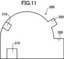
また、例えば、図11に示すように、トンネルなどの構造物内には、照明や、換気装置などの壁面から突起する部位310や、避難経路などの壁面から引っ込んだ部位320が存在する。これに対して、本実施形態では、断面形状データが離散データであり、光学縦断面内位置推定部133は、RANSACアルゴリズムにより離散データにおける外れ値を除去し、マッチングを行っているため、このような突起する部位や引っ込んだ部位の影響を排除し、マッチングを行うことができる。For example, as shown in Fig. 11, within a structure such as a tunnel, there are
また、トンネルなどの同断面形状が連続するような構造物の内部空間を飛行する際には、奥行き方向の位置を特定するのが困難である。これに対して、本実施形態では、第1のカメラ108によりトンネルの底面を撮影し、画像横方向位置推定部132が、第1のカメラ108により撮像した画像に基づき位置を推定するため、奥行き方向の位置を推定することができる。In addition, when flying through the internal space of a structure such as a tunnel that has a continuous cross-sectional shape, it is difficult to identify the position in the depth direction. In contrast, in this embodiment, the
また、本実施形態では、横断面測定装置111により測定された横断面測定データに、直線(線分)をマッチングし、光学横断面内位置/姿勢推定部134がマッチングした直線に対する自己位置及び姿勢に基づき、無人航空機の横断面内位置(壁面からの距離)及びヘディングθを推定している。これにより、トンネル内部空間内における自己位置を正確に推定することができる。さらに、無人航空機1の横断面内位置(壁面からの距離)及びヘディングθを推定することができるため、トンネルの横方向の形状が不明であっても、壁面に沿った飛行が可能になる。In addition, in this embodiment, a straight line (line segment) is matched to the cross-section measurement data measured by the
また、本実施形態では、光学横断面内位置/姿勢推定部134は、横断面測定データに対して線分をマッチングし、マッチングした線分に対する位置及び姿勢を推定している。このように、線分をマッチングすることにより、トンネルが横方向に湾曲して延びていたとしても、トンネルの壁面の接線方向と略平行にヘディングを調整することができ、トンネル壁面に沿った自律飛行が可能になる。In addition, in this embodiment, the optical cross-sectional position/
なお、本実施形態では、縦断面が半円形のトンネルにおいて無人航空機が飛行する場合について説明したが、本発明はこれに限られない。例えば、図12に示すように、縦断面において内壁面402の上部402Aが半円形であり、下部402Bが矩形状であるような形状のトンネルにおいても本発明を適用できる。このような場合には、縦断面において円をマッチングする際に、円の中心の底面(すなわち、底面に対応する箇所にマッチングした直線)を基準とした位置が、底面から上方に下部402Bの高さbの位置の近傍(高さb±Δbの範囲内)に位置するように、「正しいモデル候補」を選択するとよい。In this embodiment, the unmanned aerial vehicle flies in a tunnel with a semicircular cross section, but the present invention is not limited to this. For example, as shown in FIG. 12, the present invention can also be applied to a tunnel in which the
また、本実施形態では、自己位置データ生成部135が、画像横方向位置推定部132により推定された横方向位置(XA,YA)と、光学縦断面内位置推定部133により推定された縦断面内位置(YB、ZB)と、光学横断面内位置/姿勢推定部134により推定された縦断面内位置(トンネル内壁面からのY方向距離l)及びヘディングθに基づき自己位置データを生成しているが、本発明はこれに限られない。例えば、縦断面測定装置112及び光学縦断面内位置推定部133を省略することも可能である。この場合には、X座標については横方向位置を用い、Y座標及びヘディングθについては縦断面内位置から算出し、高さ(Z座標)については高度計を用いて決定すればよい。このような構成によっても、トンネル壁面に沿った自律飛行が可能である。 In this embodiment, the self-position
また、例えば、横断面測定装置111及び光学横断面内位置/姿勢推定部134を省略することも可能であり、この場合には、X座標については横方向位置を用い、Y座標及びZ座標については縦断面内位置を用いる。そして、ヘディングθについては、例えば、無人航空機が前方などの所定の方向に飛行した際の時間微分から求めることも可能である。このような構成によっても、トンネル内の自己位置を正確に推定することが可能である。It is also possible, for example, to omit the cross
また、本実施形態では、トンネルが、縦断面形状が半円形であり、長手方向に同断面形状で延びる形状であり、トンネルの縦断面形状に対して円をマッチングし、トンネルの横断面に対して直線をマッチングする場合について説明したが、本発明はこれに限られない。すなわち、トンネルの縦断面形状の一部に、円形や、楕円形、矩形等の幾何学的形状が含まれていれば、幾何学的形状によるマッチングを行うことができる。また、横断面に関しても、トンネルが円弧状に延びているなど、トンネルの横断面形状に幾何学的形状が含まれていれば、幾何学的形状によるマッチングを行うことができる。なお、縦断面においてマッチングする形状としては二次元形状(直線は含まない)が好ましい。In addition, in this embodiment, the tunnel has a semicircular cross-sectional shape that extends in the longitudinal direction, and a circle is matched to the longitudinal cross-sectional shape of the tunnel, and a straight line is matched to the cross-sectional shape of the tunnel, but the present invention is not limited to this. In other words, if part of the longitudinal cross-sectional shape of the tunnel includes a geometric shape such as a circle, ellipse, or rectangle, matching based on the geometric shape can be performed. In addition, with regard to the cross-sectional shape, if the cross-sectional shape of the tunnel includes a geometric shape, such as if the tunnel extends in an arc, matching based on the geometric shape can be performed. Note that a two-dimensional shape (not including a straight line) is preferable as the shape to be matched in the longitudinal cross-section.
また、本実施形態では、第1のカメラ108により撮像した画像に基づき、画像横方向位置推定部132が横方向自己位置(XA,YA)を推定し、これに基づき無人航空機1のX座標(奥行き方向の位置)を特定しているが、これに限らず、IMUによりX座標を特定してもよい。 Furthermore, in this embodiment, the image lateral
また、本実施形態では、トンネルが水平方向に延びている場合について説明したがこれに限らず、傾斜している場合などであっても、本発明を適用できる。このような場合には、横方向として斜めに傾斜するように設定してもよいし、水平方向を設定してもよい。また、縦断面としても垂直断面を設定してもよいし、斜めに傾斜する横方向に対する垂直断面としてもよい。In this embodiment, the tunnel extends horizontally, but the present invention can be applied to cases where the tunnel is inclined. In such cases, the horizontal direction may be set to be inclined at an angle, or the horizontal direction may be set. Furthermore, the longitudinal section may be set to be a vertical section, or the vertical section may be set to be a vertical section relative to the horizontal direction that is inclined at an angle.
1 無人航空機
2 ステップ
3 ステップ
5 ステップ
101 制御ユニット
102 モータ
103 ロータ
104 アーム
105 着陸脚
106 台座
107 支持部材
108 第1のカメラ
109 第2のカメラ
110 架台
111 横断面測定装置
112 縦断面測定装置
117 アンテナ
120 情報処理ユニット
121 通信回路
122 制御信号生成部
123 スピードコントローラ
125 インターフェイス
130 断面形状データ記憶部
131 飛行経路データ記憶部
132 画像横方向位置推定部
133 光学縦断面内位置推定部
134 光学横断面内位置/姿勢推定部
135 自己位置データ生成部
136 飛行制御部
140 自己位置推定システム
200 飛行制御システム1 Unmanned
Claims (15)
Translated fromJapanese前記無人航空機は、前記無人航空機の飛行経路を横切る方向の縦断面内の空間形状を測定し、縦断面測定データを生成する縦断面測定装置を含み、
前記無人航空機が、横方向に所定の経路に沿って延びる構造物の内部空間を飛行するときに、前記縦断面測定装置により生成された前記縦断面測定データを取得する縦断面測定データ取得部と、
前記縦断面測定データ取得部が取得した前記縦断面測定データに、前記構造物の内壁面に対応する第1の所定形状をマッチングし、当該マッチングした所定形状に対する自己位置に基づき、前記縦断面内における前記無人航空機の縦断面内位置を推定する縦断面内位置推定部と、
前記無人航空機は、前記無人航空機の所定の方向を基準とした横断面内の空間形状を測定し、横断面測定データを生成するための横断面測定装置をさらに含み、
前記無人航空機が、前記横方向に所定の経路に沿って延びる構造物の内部空間を飛行するときに、前記横断面測定装置が生成した前記横断面測定データを取得する横断面測定データ取得部と、
前記横断面測定データ取得部が取得した前記横断面測定データに第2の所定形状をマッチングし、当該マッチングした第2の所定形状に対する自己位置及び/又は姿勢に基づき、前記無人航空機の横断面内位置及び/又は姿勢を推定する光学断面内位置/姿勢推定部と、
を含む、自己位置推定システム。A self-position estimation system for estimating a self-position of an unmanned aerial vehiclein a horizontally extending tunnel , comprising:
The unmanned aerial vehicle includes a longitudinal section measurement device that measures a spatial shape within a longitudinal section in a direction intersecting a flight path of the unmanned aerial vehicle and generates longitudinal section measurement data;
a longitudinal section measurement data acquisition unit that acquires the longitudinal section measurement data generated by the longitudinal section measurement device when the unmanned aerial vehicle flies through an interior space of a structure extending laterally along a predetermined path;
a longitudinal section position estimation unit that matches a first predetermined shape corresponding to an inner wall surface of the structure to the longitudinal section measurement data acquired by the longitudinal section measurement data acquisition unit, and estimates a position of the unmanned aerial vehicle in the longitudinal section based on its own position relative to the matched predetermined shape;
The unmanned aerial vehicle further includes a cross section measurement device for measuring a spatial shape within a cross section based on a predetermined direction of the unmanned aerial vehicle and generating cross section measurement data;
a cross-section measurement data acquisition unit that acquires the cross-section measurement data generated by the cross-section measurement device when the unmanned aerial vehicle flies through an interior space of a structure extending along a predetermined path in the lateral direction;
an optical cross-sectional position/attitude estimation unit that matches a second predetermined shape to the cross-sectional measurement data acquired by the cross-sectional measurement data acquisition unit and estimates a cross-sectional position and/or attitude of the unmanned aerial vehicle based on its own position and/or attitude with respect to the matched second predetermined shape;
A self-location estimation system comprising:
前記縦断面内位置推定部は、前記縦断面測定データに対して前記幾何学的形状をマッチングし、前記マッチングした幾何学的形状に対する自己位置に基づき、前記縦断面内位置を推定する、
請求項1に記載の自己位置推定システム。 the first predetermined shape corresponds at least in part to a geometric shape;
the longitudinal section position estimation unit matches the geometric shape to the longitudinal section measurement data, and estimates the position in the longitudinal section based on a self-position with respect to the matched geometric shape;
The self-location estimation system according to claim 1 .
請求項2に記載の自己位置推定システム。 The geometric shape is a shape formed by a convex curve.
The self-location estimation system according to claim 2 .
請求項3に記載の自己位置推定システム。 The geometric shape is at least one of a partial or complete circle and a partial or complete ellipse.
The self-location estimation system according to claim 3 .
前記マッチングした第3の所定形状に対して所定の高さ範囲内に位置するように前記第1の所定形状をマッチングする、
請求項1~4の何れか1項に記載の自己位置推定システム。 the longitudinal section position estimation unit matches a third predetermined shape corresponding to a bottom surface of the structure to the longitudinal section measurement data;
matching the first predetermined shape to be located within a predetermined height range with respect to the matched third predetermined shape;
The self-location estimation system according to any one of claims 1 to 4.
前記縦断面内位置推定部は、前記離散データにおける外れ値を除去し、マッチングを行う、
請求項1~5の何れか1項に記載の自己位置推定システム。 The longitudinal section measurement data is discrete data;
The longitudinal section position estimation unit removes outliers in the discrete data and performs matching.
A self-location estimation system according to any one of claims 1 to 5.
前記無人航空機の飛行中に前記撮像装置により連続的に撮像された画像から前記無人航空機の横方向自己位置を推定する画像横方向位置推定部をさらに含む、
請求項1~6の何れか1項に記載の自己位置推定システム。 The unmanned aerial vehicle further includes an imaging device capable of imaging an area below the unmanned aerial vehicle,
The image lateral position estimation unit estimates a lateral position of the unmanned aerial vehicle from images continuously captured by the imaging device during flight of the unmanned aerial vehicle.
A self-location estimation system according to any one of claims 1 to 6.
請求項1に記載の自己位置推定システム。 The second predetermined shape is at least partially in the shape of a line segment or an arc.
The self-location estimation system according to claim 1 .
請求項1に記載の自己位置推定システム。 The second predetermined shape is a line segment.
The self-location estimation system according to claim1 .
前記自己位置推定システムにより推定された自己位置に基づき、設定された飛行計画経路に沿って無人航空機を飛行させる飛行制御部と、を含む、
無人航空機の飛行制御システム。 A self-location estimation system according to any one of claims 1 to 9,
A flight control unit that flies the unmanned aircraft along a set flight plan route based on the self-position estimated by the self-position estimation system.
Unmanned aerial vehicle flight control system.
前記無人航空機の飛行経路を横切る方向の縦断面内の空間形状を測定し、縦断面測定データを生成する縦断面測定装置から、前記無人航空機が横方向に所定の経路に沿って延びる構造物の内部空間を飛行するときに、前記縦断面測定データを取得する縦断面測定データ取得ステップと、
前記縦断面測定データ取得ステップにおいて取得した前記縦断面測定データに、第1の所定形状をマッチングし、当該マッチングした所定形状に対する自己位置に基づき、前記縦断面内における前記無人航空機の縦断面内位置を推定する縦断面内位置推定ステップと、
無人航空機の所定の方向を基準とした横断面内の空間形状を測定し、横断面測定データを生成する横断面測定装置から、前記無人航空機が、横方向に所定の経路に沿って延びる構造物の内部空間を飛行するときに、前記横断面測定データを取得する横断面測定データ取得ステップと、
前記横断面測定データ取得ステップにおいて取得した前記横断面測定データに、第2の所定形状をマッチングし、当該マッチングした第2の所定形状に対する自己位置及び/又は姿勢に基づき、前記無人航空機の横方向位置及び/又は姿勢を推定する横断面内位置/姿勢推定ステップと、
を含む、自己位置推定方法。A method for estimating a self-position of an unmanned aerial vehiclein a horizontally extending tunnel by a computer, comprising:
a longitudinal section measurement data acquisition step of acquiring the longitudinal section measurement data from a longitudinal section measurement device that measures a spatial shape within a longitudinal section in a direction transverse to the flight path of the unmanned aerial vehicle and generates the longitudinal section measurement data when the unmanned aerial vehicle flies through an internal space of a structure extending along a predetermined path in a lateral direction;
a longitudinal section position estimation step of matching a first predetermined shape to the longitudinal section measurement data acquired in the longitudinal section measurement data acquisition step, and estimating a position of the unmanned aerial vehicle in the longitudinal section based on its own position with respect to the matched predetermined shape;
a cross-sectional measurement data acquisition step of acquiring, from a cross-sectional measurement device that measures a spatial shape within a cross-section based on a predetermined direction of the unmanned aerial vehicle and generates cross-sectional measurement data, the cross-sectional measurement data when the unmanned aerial vehicle flies through an interior space of a structure extending laterally along a predetermined path;
a transverse plane position/attitude estimation step of matching a second predetermined shape to the transverse plane measurement data acquired in the transverse plane measurement data acquisition step, and estimating a lateral position and/or attitude of the unmanned aerial vehicle based on its own position and/or attitude relative to the matched second predetermined shape;
A self-location estimation method comprising:
Applications Claiming Priority (1)
| Application Number | Priority Date | Filing Date | Title |
|---|---|---|---|
| PCT/JP2021/000813WO2022153390A1 (en) | 2021-01-13 | 2021-01-13 | Self-position estimation system for estimating self position of uncrewed aircraft, flight control system, uncrewed aircraft, program, and recording medium |
Publications (2)
| Publication Number | Publication Date |
|---|---|
| JPWO2022153390A1 JPWO2022153390A1 (en) | 2022-07-21 |
| JP7626478B2true JP7626478B2 (en) | 2025-02-04 |
Family
ID=82446979
Family Applications (1)
| Application Number | Title | Priority Date | Filing Date |
|---|---|---|---|
| JP2022574907AActiveJP7626478B2 (en) | 2021-01-13 | 2021-01-13 | Self-position estimation system for estimating the self-position of an unmanned aerial vehicle, flight control system, unmanned aerial vehicle, program, and recording medium |
Country Status (2)
| Country | Link |
|---|---|
| JP (1) | JP7626478B2 (en) |
| WO (1) | WO2022153390A1 (en) |
Citations (7)
| Publication number | Priority date | Publication date | Assignee | Title |
|---|---|---|---|---|
| JP2006016858A (en) | 2004-07-02 | 2006-01-19 | Toko Corp | Method and apparatus for preventing fallen object in chimney |
| JP2011008320A (en) | 2009-06-23 | 2011-01-13 | Toyota Motor Corp | Autonomous mobile unit, self position estimating device, and program |
| JP2017075863A (en) | 2015-10-15 | 2017-04-20 | 株式会社プロドローン | Aerial type inspection device and inspection method |
| CN109031312A (en) | 2018-04-26 | 2018-12-18 | 中国计量大学 | Flying platform positioning device and localization method suitable for chimney inside processing |
| WO2019190398A1 (en) | 2018-03-26 | 2019-10-03 | Singapore University Of Technology And Design | Aerial vehicles, methods of imaging a tunnel and methods of imaging a shaft |
| JP2019167044A (en) | 2018-03-26 | 2019-10-03 | 株式会社日立製作所 | Unmanned flight body introduction device, in-conduit line work system and work method using unmanned flight body |
| JP2020176961A (en) | 2019-04-20 | 2020-10-29 | 三精システム株式会社 | Drone with self-position measuring function |
- 2021
- 2021-01-13JPJP2022574907Apatent/JP7626478B2/enactiveActive
- 2021-01-13WOPCT/JP2021/000813patent/WO2022153390A1/ennot_activeCeased
Patent Citations (7)
| Publication number | Priority date | Publication date | Assignee | Title |
|---|---|---|---|---|
| JP2006016858A (en) | 2004-07-02 | 2006-01-19 | Toko Corp | Method and apparatus for preventing fallen object in chimney |
| JP2011008320A (en) | 2009-06-23 | 2011-01-13 | Toyota Motor Corp | Autonomous mobile unit, self position estimating device, and program |
| JP2017075863A (en) | 2015-10-15 | 2017-04-20 | 株式会社プロドローン | Aerial type inspection device and inspection method |
| WO2019190398A1 (en) | 2018-03-26 | 2019-10-03 | Singapore University Of Technology And Design | Aerial vehicles, methods of imaging a tunnel and methods of imaging a shaft |
| JP2019167044A (en) | 2018-03-26 | 2019-10-03 | 株式会社日立製作所 | Unmanned flight body introduction device, in-conduit line work system and work method using unmanned flight body |
| CN109031312A (en) | 2018-04-26 | 2018-12-18 | 中国计量大学 | Flying platform positioning device and localization method suitable for chimney inside processing |
| JP2020176961A (en) | 2019-04-20 | 2020-10-29 | 三精システム株式会社 | Drone with self-position measuring function |
Also Published As
| Publication number | Publication date |
|---|---|
| WO2022153390A1 (en) | 2022-07-21 |
| JPWO2022153390A1 (en) | 2022-07-21 |
Similar Documents
| Publication | Publication Date | Title |
|---|---|---|
| US11822353B2 (en) | Simple multi-sensor calibration | |
| US10565732B2 (en) | Sensor fusion using inertial and image sensors | |
| US11218689B2 (en) | Methods and systems for selective sensor fusion | |
| EP3158293B1 (en) | Sensor fusion using inertial and image sensors | |
| EP3158417B1 (en) | Sensor fusion using inertial and image sensors | |
| EP3158411B1 (en) | Sensor fusion using inertial and image sensors | |
| US11032527B2 (en) | Unmanned aerial vehicle surface projection | |
| WO2022042184A1 (en) | Method and apparatus for estimating position of tracking target, and unmanned aerial vehicle | |
| WO2017177542A1 (en) | Object tracking method, device and system | |
| Roca et al. | Lidar-equipped uav for building information modelling | |
| JP6138326B1 (en) | MOBILE BODY, MOBILE BODY CONTROL METHOD, PROGRAM FOR CONTROLLING MOBILE BODY, CONTROL SYSTEM, AND INFORMATION PROCESSING DEVICE | |
| US20210229810A1 (en) | Information processing device, flight control method, and flight control system | |
| JP2022134194A (en) | Forest measurement system, forest measurement method and computer program | |
| KR20220086479A (en) | Aircraft sensor system synchronization | |
| JP7620992B2 (en) | Self-location estimation system and method for unmanned aerial vehicle, unmanned aerial vehicle, program, and storage medium | |
| WO2020062356A1 (en) | Control method, control apparatus, control terminal for unmanned aerial vehicle | |
| JP7626478B2 (en) | Self-position estimation system for estimating the self-position of an unmanned aerial vehicle, flight control system, unmanned aerial vehicle, program, and recording medium | |
| US11514597B1 (en) | Single-camera stereoaerophotogrammetry using UAV sensors | |
| JP7638493B2 (en) | Estimation system for estimating self-position and/or attitude of unmanned aerial vehicle, flight control system, unmanned aerial vehicle, program, and recording medium | |
| WO2021232296A1 (en) | Method for controlling unmanned aerial vehicle, device, unmanned aerial vehicle, and storage medium | |
| JP2020160019A (en) | Method for measuring three-dimensional shape of object | |
| CN110892353A (en) | Control method, control device and control terminal of unmanned aerial vehicle | |
| WO2024004155A1 (en) | System, subsystem, method and program for estimating position of wind-power generation device, and storage medium having said program therein |
Legal Events
| Date | Code | Title | Description |
|---|---|---|---|
| A621 | Written request for application examination | Free format text:JAPANESE INTERMEDIATE CODE: A621 Effective date:20231011 | |
| A131 | Notification of reasons for refusal | Free format text:JAPANESE INTERMEDIATE CODE: A131 Effective date:20240627 | |
| A601 | Written request for extension of time | Free format text:JAPANESE INTERMEDIATE CODE: A601 Effective date:20240826 | |
| A521 | Request for written amendment filed | Free format text:JAPANESE INTERMEDIATE CODE: A523 Effective date:20241024 | |
| TRDD | Decision of grant or rejection written | ||
| A01 | Written decision to grant a patent or to grant a registration (utility model) | Free format text:JAPANESE INTERMEDIATE CODE: A01 Effective date:20241217 | |
| A61 | First payment of annual fees (during grant procedure) | Free format text:JAPANESE INTERMEDIATE CODE: A61 Effective date:20250116 | |
| R150 | Certificate of patent or registration of utility model | Ref document number:7626478 Country of ref document:JP Free format text:JAPANESE INTERMEDIATE CODE: R150 |