JP7626091B2 - Vehicle control device - Google Patents
Vehicle control deviceDownload PDFInfo
- Publication number
- JP7626091B2 JP7626091B2JP2022054458AJP2022054458AJP7626091B2JP 7626091 B2JP7626091 B2JP 7626091B2JP 2022054458 AJP2022054458 AJP 2022054458AJP 2022054458 AJP2022054458 AJP 2022054458AJP 7626091 B2JP7626091 B2JP 7626091B2
- Authority
- JP
- Japan
- Prior art keywords
- vehicle
- platoon
- participating
- vehicles
- control device
- Prior art date
- Legal status (The legal status is an assumption and is not a legal conclusion. Google has not performed a legal analysis and makes no representation as to the accuracy of the status listed.)
- Active
Links
Images


Classifications
- B—PERFORMING OPERATIONS; TRANSPORTING
- B60—VEHICLES IN GENERAL
- B60W—CONJOINT CONTROL OF VEHICLE SUB-UNITS OF DIFFERENT TYPE OR DIFFERENT FUNCTION; CONTROL SYSTEMS SPECIALLY ADAPTED FOR HYBRID VEHICLES; ROAD VEHICLE DRIVE CONTROL SYSTEMS FOR PURPOSES NOT RELATED TO THE CONTROL OF A PARTICULAR SUB-UNIT
- B60W30/00—Purposes of road vehicle drive control systems not related to the control of a particular sub-unit, e.g. of systems using conjoint control of vehicle sub-units
- B60W30/14—Adaptive cruise control
- B60W30/16—Control of distance between vehicles, e.g. keeping a distance to preceding vehicle
- G—PHYSICS
- G05—CONTROLLING; REGULATING
- G05D—SYSTEMS FOR CONTROLLING OR REGULATING NON-ELECTRIC VARIABLES
- G05D1/00—Control of position, course, altitude or attitude of land, water, air or space vehicles, e.g. using automatic pilots
- G05D1/02—Control of position or course in two dimensions
- G05D1/021—Control of position or course in two dimensions specially adapted to land vehicles
- G05D1/0287—Control of position or course in two dimensions specially adapted to land vehicles involving a plurality of land vehicles, e.g. fleet or convoy travelling
- G05D1/0291—Fleet control
- G05D1/0293—Convoy travelling
- B—PERFORMING OPERATIONS; TRANSPORTING
- B60—VEHICLES IN GENERAL
- B60W—CONJOINT CONTROL OF VEHICLE SUB-UNITS OF DIFFERENT TYPE OR DIFFERENT FUNCTION; CONTROL SYSTEMS SPECIALLY ADAPTED FOR HYBRID VEHICLES; ROAD VEHICLE DRIVE CONTROL SYSTEMS FOR PURPOSES NOT RELATED TO THE CONTROL OF A PARTICULAR SUB-UNIT
- B60W10/00—Conjoint control of vehicle sub-units of different type or different function
- B60W10/04—Conjoint control of vehicle sub-units of different type or different function including control of propulsion units
- B60W10/06—Conjoint control of vehicle sub-units of different type or different function including control of propulsion units including control of combustion engines
- B—PERFORMING OPERATIONS; TRANSPORTING
- B60—VEHICLES IN GENERAL
- B60W—CONJOINT CONTROL OF VEHICLE SUB-UNITS OF DIFFERENT TYPE OR DIFFERENT FUNCTION; CONTROL SYSTEMS SPECIALLY ADAPTED FOR HYBRID VEHICLES; ROAD VEHICLE DRIVE CONTROL SYSTEMS FOR PURPOSES NOT RELATED TO THE CONTROL OF A PARTICULAR SUB-UNIT
- B60W10/00—Conjoint control of vehicle sub-units of different type or different function
- B60W10/10—Conjoint control of vehicle sub-units of different type or different function including control of change-speed gearings
- B—PERFORMING OPERATIONS; TRANSPORTING
- B60—VEHICLES IN GENERAL
- B60W—CONJOINT CONTROL OF VEHICLE SUB-UNITS OF DIFFERENT TYPE OR DIFFERENT FUNCTION; CONTROL SYSTEMS SPECIALLY ADAPTED FOR HYBRID VEHICLES; ROAD VEHICLE DRIVE CONTROL SYSTEMS FOR PURPOSES NOT RELATED TO THE CONTROL OF A PARTICULAR SUB-UNIT
- B60W10/00—Conjoint control of vehicle sub-units of different type or different function
- B60W10/18—Conjoint control of vehicle sub-units of different type or different function including control of braking systems
- B—PERFORMING OPERATIONS; TRANSPORTING
- B60—VEHICLES IN GENERAL
- B60W—CONJOINT CONTROL OF VEHICLE SUB-UNITS OF DIFFERENT TYPE OR DIFFERENT FUNCTION; CONTROL SYSTEMS SPECIALLY ADAPTED FOR HYBRID VEHICLES; ROAD VEHICLE DRIVE CONTROL SYSTEMS FOR PURPOSES NOT RELATED TO THE CONTROL OF A PARTICULAR SUB-UNIT
- B60W30/00—Purposes of road vehicle drive control systems not related to the control of a particular sub-unit, e.g. of systems using conjoint control of vehicle sub-units
- B60W30/14—Adaptive cruise control
- B60W30/16—Control of distance between vehicles, e.g. keeping a distance to preceding vehicle
- B60W30/165—Automatically following the path of a preceding lead vehicle, e.g. "electronic tow-bar"
- B—PERFORMING OPERATIONS; TRANSPORTING
- B60—VEHICLES IN GENERAL
- B60W—CONJOINT CONTROL OF VEHICLE SUB-UNITS OF DIFFERENT TYPE OR DIFFERENT FUNCTION; CONTROL SYSTEMS SPECIALLY ADAPTED FOR HYBRID VEHICLES; ROAD VEHICLE DRIVE CONTROL SYSTEMS FOR PURPOSES NOT RELATED TO THE CONTROL OF A PARTICULAR SUB-UNIT
- B60W40/00—Estimation or calculation of non-directly measurable driving parameters for road vehicle drive control systems not related to the control of a particular sub unit, e.g. by using mathematical models
- B60W40/12—Estimation or calculation of non-directly measurable driving parameters for road vehicle drive control systems not related to the control of a particular sub unit, e.g. by using mathematical models related to parameters of the vehicle itself, e.g. tyre models
- B60W40/13—Load or weight
- G—PHYSICS
- G05—CONTROLLING; REGULATING
- G05D—SYSTEMS FOR CONTROLLING OR REGULATING NON-ELECTRIC VARIABLES
- G05D1/00—Control of position, course, altitude or attitude of land, water, air or space vehicles, e.g. using automatic pilots
- G05D1/02—Control of position or course in two dimensions
- G05D1/021—Control of position or course in two dimensions specially adapted to land vehicles
- G05D1/0212—Control of position or course in two dimensions specially adapted to land vehicles with means for defining a desired trajectory
- G05D1/0217—Control of position or course in two dimensions specially adapted to land vehicles with means for defining a desired trajectory in accordance with energy consumption, time reduction or distance reduction criteria
- G—PHYSICS
- G05—CONTROLLING; REGULATING
- G05D—SYSTEMS FOR CONTROLLING OR REGULATING NON-ELECTRIC VARIABLES
- G05D1/00—Control of position, course, altitude or attitude of land, water, air or space vehicles, e.g. using automatic pilots
- G05D1/02—Control of position or course in two dimensions
- G05D1/021—Control of position or course in two dimensions specially adapted to land vehicles
- G05D1/0287—Control of position or course in two dimensions specially adapted to land vehicles involving a plurality of land vehicles, e.g. fleet or convoy travelling
- G05D1/0291—Fleet control
- G05D1/0295—Fleet control by at least one leading vehicle of the fleet
- G—PHYSICS
- G05—CONTROLLING; REGULATING
- G05D—SYSTEMS FOR CONTROLLING OR REGULATING NON-ELECTRIC VARIABLES
- G05D1/00—Control of position, course, altitude or attitude of land, water, air or space vehicles, e.g. using automatic pilots
- G05D1/20—Control system inputs
- G05D1/22—Command input arrangements
- G05D1/221—Remote-control arrangements
- G05D1/225—Remote-control arrangements operated by off-board computers
- G—PHYSICS
- G08—SIGNALLING
- G08G—TRAFFIC CONTROL SYSTEMS
- G08G1/00—Traffic control systems for road vehicles
- G08G1/22—Platooning, i.e. convoy of communicating vehicles
- B—PERFORMING OPERATIONS; TRANSPORTING
- B60—VEHICLES IN GENERAL
- B60W—CONJOINT CONTROL OF VEHICLE SUB-UNITS OF DIFFERENT TYPE OR DIFFERENT FUNCTION; CONTROL SYSTEMS SPECIALLY ADAPTED FOR HYBRID VEHICLES; ROAD VEHICLE DRIVE CONTROL SYSTEMS FOR PURPOSES NOT RELATED TO THE CONTROL OF A PARTICULAR SUB-UNIT
- B60W2554/00—Input parameters relating to objects
- B60W2554/80—Spatial relation or speed relative to objects
- B—PERFORMING OPERATIONS; TRANSPORTING
- B60—VEHICLES IN GENERAL
- B60W—CONJOINT CONTROL OF VEHICLE SUB-UNITS OF DIFFERENT TYPE OR DIFFERENT FUNCTION; CONTROL SYSTEMS SPECIALLY ADAPTED FOR HYBRID VEHICLES; ROAD VEHICLE DRIVE CONTROL SYSTEMS FOR PURPOSES NOT RELATED TO THE CONTROL OF A PARTICULAR SUB-UNIT
- B60W2556/00—Input parameters relating to data
- B60W2556/45—External transmission of data to or from the vehicle
- B—PERFORMING OPERATIONS; TRANSPORTING
- B60—VEHICLES IN GENERAL
- B60W—CONJOINT CONTROL OF VEHICLE SUB-UNITS OF DIFFERENT TYPE OR DIFFERENT FUNCTION; CONTROL SYSTEMS SPECIALLY ADAPTED FOR HYBRID VEHICLES; ROAD VEHICLE DRIVE CONTROL SYSTEMS FOR PURPOSES NOT RELATED TO THE CONTROL OF A PARTICULAR SUB-UNIT
- B60W2710/00—Output or target parameters relating to a particular sub-units
- B60W2710/06—Combustion engines, Gas turbines
- B60W2710/0666—Engine torque
- B—PERFORMING OPERATIONS; TRANSPORTING
- B60—VEHICLES IN GENERAL
- B60W—CONJOINT CONTROL OF VEHICLE SUB-UNITS OF DIFFERENT TYPE OR DIFFERENT FUNCTION; CONTROL SYSTEMS SPECIALLY ADAPTED FOR HYBRID VEHICLES; ROAD VEHICLE DRIVE CONTROL SYSTEMS FOR PURPOSES NOT RELATED TO THE CONTROL OF A PARTICULAR SUB-UNIT
- B60W2710/00—Output or target parameters relating to a particular sub-units
- B60W2710/10—Change speed gearings
- B60W2710/1005—Transmission ratio engaged
- B—PERFORMING OPERATIONS; TRANSPORTING
- B60—VEHICLES IN GENERAL
- B60W—CONJOINT CONTROL OF VEHICLE SUB-UNITS OF DIFFERENT TYPE OR DIFFERENT FUNCTION; CONTROL SYSTEMS SPECIALLY ADAPTED FOR HYBRID VEHICLES; ROAD VEHICLE DRIVE CONTROL SYSTEMS FOR PURPOSES NOT RELATED TO THE CONTROL OF A PARTICULAR SUB-UNIT
- B60W2710/00—Output or target parameters relating to a particular sub-units
- B60W2710/18—Braking system
- B—PERFORMING OPERATIONS; TRANSPORTING
- B60—VEHICLES IN GENERAL
- B60W—CONJOINT CONTROL OF VEHICLE SUB-UNITS OF DIFFERENT TYPE OR DIFFERENT FUNCTION; CONTROL SYSTEMS SPECIALLY ADAPTED FOR HYBRID VEHICLES; ROAD VEHICLE DRIVE CONTROL SYSTEMS FOR PURPOSES NOT RELATED TO THE CONTROL OF A PARTICULAR SUB-UNIT
- B60W2754/00—Output or target parameters relating to objects
- B60W2754/10—Spatial relation or speed relative to objects
- B60W2754/30—Longitudinal distance
Landscapes
- Engineering & Computer Science (AREA)
- Automation & Control Theory (AREA)
- Mechanical Engineering (AREA)
- Transportation (AREA)
- Physics & Mathematics (AREA)
- General Physics & Mathematics (AREA)
- Combustion & Propulsion (AREA)
- Chemical & Material Sciences (AREA)
- Remote Sensing (AREA)
- Radar, Positioning & Navigation (AREA)
- Aviation & Aerospace Engineering (AREA)
- Mathematical Physics (AREA)
- Control Of Driving Devices And Active Controlling Of Vehicle (AREA)
Description
Translated fromJapanese本発明は、先頭車両と追従車両とを含む隊列参加車両による隊列走行を制御する車両用制御装置に関するものである。The present invention relates to a vehicle control device that controls platoon driving by vehicles participating in a platoon, including a leading vehicle and a following vehicle.
先頭車両と、前記先頭車両に対して所定の車間距離ずつ隔てて1列で自動で追従走行する追従車両と、を含む隊列参加車両の各々を無線通信を介して接続し、前記隊列参加車両による隊列走行を制御する車両用制御装置が良く知られている。例えば、特許文献1に記載された隊列走行制御装置がそれである。この特許文献1には、加速走行と、減速走行又は惰性走行と、を交互に繰り返すことによって車速を目標車速に制御する為の走行計画に基づいて、隊列を組む車両を決定することが開示されている。A well-known vehicle control device connects each of the vehicles participating in a platoon, including a lead vehicle and a following vehicle that automatically follows the lead vehicle in a single file at a specified distance from the lead vehicle, via wireless communication and controls the platooning of the vehicles participating in the platoon. One example is the platooning control device described in
ところで、隊列走行中に車速を維持するように走行する場合、例えば要求駆動トルクをゼロとして成り行きで減速する慣性走行時つまり惰性走行時に各隊列参加車両の走行抵抗の違いによって隊列参加車両間の車間距離が短くなってしまうおそれがあった。However, when vehicles are traveling in a convoy to maintain their vehicle speed, for example when the required drive torque is set to zero and the vehicles are coasting, which means that they are decelerating naturally, there is a risk that the distance between the vehicles in the convoy will become shorter due to differences in the running resistance of each vehicle.
本発明は、以上の事情を背景として為されたものであり、その目的とするところは、隊列走行中の惰性走行時に隊列参加車両間の車間距離が短くなることを抑制することができる車両用制御装置を提供することにある。The present invention was made against the background of the above circumstances, and its purpose is to provide a vehicle control device that can prevent the inter-vehicle distance between vehicles in a platoon from becoming shorter when the vehicles are coasting during platooning.
第1の発明の要旨とするところは、(a)先頭車両と、前記先頭車両に対して所定の車間距離ずつ隔てて1列で自動で追従走行する追従車両と、を含む隊列参加車両の各々を無線通信を介して接続し、前記隊列参加車両による隊列走行を制御する車両用制御装置であって、(b)前記隊列走行の実行中には、前記隊列参加車両毎に現在の車両状態において単独で惰性走行したときの被駆動トルクに基づく減速度の推定値の情報を取得し、前記隊列参加車両の並び順を前記先頭車両から順に前記減速度の推定値が大きくなる並び順とするように、前記隊列参加車両の各々における前記被駆動トルクを制御するものであり、(c)動力源として回転機を備えた前記隊列参加車両では、前記回転機の回生作動による回生ブレーキによって得られる前記被駆動トルクを、前記回転機の回生量を変更することで制御することにある。 The gist of the first invention is that (a) a vehicle control device that connects each of the platoon participating vehicles, including a lead vehicle and a following vehicle that automatically follows the lead vehicle in a single file at a predetermined distance from the lead vehicle, via wireless communication and controls the platoon traveling of the platoon participating vehicles, (b) while the platoon traveling is being performed, obtains information on an estimated deceleration value based on the driven torque when the platoon participating vehicles are coasting alone in their current vehicle state, and controls the driven torque of each of the platoon participating vehicles so that the platoon participating vehicles are arrangedin order of the estimated deceleration value increasing from the lead vehicle, and (c) in the platoon participating vehicles equipped with a rotating machine as a power source, the driven torque obtained by regenerative braking due to regenerative operation of the rotating machine is controlled by changing the amount of regeneration of the rotating machine .
また、第2の発明の要旨とするところは、(a)先頭車両と、前記先頭車両に対して所定の車間距離ずつ隔てて1列で自動で追従走行する追従車両と、を含む隊列参加車両の各々を無線通信を介して接続し、前記隊列参加車両による隊列走行を制御する車両用制御装置であって、(b)前記隊列走行の実行中には、前記隊列参加車両毎に現在の車両状態において単独で惰性走行したときの被駆動トルクに基づく減速度の推定値の情報を取得し、前記隊列参加車両の並び順を前記先頭車両から順に前記減速度の推定値が大きくなる並び順とするように、前記隊列参加車両の各々における前記被駆動トルクを制御するものであり、(c)動力源としてのエンジンと、前記エンジンの動力を駆動輪へ伝達する自動変速機と、を備えた前記隊列参加車両では、前記エンジンのフリクションによるエンジンブレーキによって得られる前記被駆動トルクを、前記自動変速機の変速比を変更することで制御することにある。The gist of the second invention is (a) a vehicle control device that connects each of the platoon participating vehicles, including a lead vehicle and a following vehicle that automatically follows the lead vehicle in a single file at a predetermined vehicle distance apart, via wireless communication and controls the platoon traveling of the platoon participating vehicles, (b) while the platoon traveling is being performed, obtains information on an estimated deceleration value based on the driven torque when the platoon participating vehicle is coasting alone in the current vehicle state for each of the platoon participating vehicles, and controls the driven torque of each of the platoon participating vehicles so that the platoon participating vehicles are arranged in order of the estimated deceleration value increasing from the lead vehicle, and (c) in the platoon participating vehicles that are equipped with an engine as a power source and an automatic transmission that transmits the power of the engine to the drive wheels, the driven torque obtained by engine braking due to friction of the engine is controlled by changing the gear ratio of the automatic transmission.
また、第3の発明は、前記第2の発明に記載の車両用制御装置において、動力源として回転機を備えた前記隊列参加車両では、前記回転機の回生作動による回生ブレーキによって得られる前記被駆動トルクを、前記回転機の回生量を変更することで制御することにある。 In addition, the third invention is a vehicle control device described inthe second invention, in which, in a platooning vehicle equipped with a rotating machine as a power source, the driven torque obtained by regenerative braking due to the regenerative operation of the rotating machine is controlled by changing the amount of regeneration of the rotating machine.
また、第4の発明は、前記第1の発明から第3の発明の何れか1つに記載の車両用制御装置において、前記隊列参加車両の並び順による空気抵抗の差を加味した前記減速度の推定値の情報を取得することにある。The fourth invention is a vehicle control device according to any one of the first to third inventions, which obtains information on the estimated deceleration value that takes into account the difference in air resistance due to the order of the vehicles participating in the platoon.
また、第5の発明は、前記第1の発明から第4の発明の何れか1つに記載の車両用制御装置において、前記隊列参加車両毎の前記被駆動トルクに基づく前記減速度の推定値を、前記隊列走行の実行前に算出することにある。The fifth invention is a vehicle control device according to any one of the first to fourth inventions, which calculates an estimated value of the deceleration based on the driven torque of each vehicle participating in the platoon before the platoon travel is performed.
また、第6の発明は、前記第1の発明から第5の発明の何れか1つに記載の車両用制御装置において、前記隊列参加車両毎の前記被駆動トルクに基づく前記減速度の推定値を、車両重量に基づいて算出することにある。The sixth aspect of the present invention is a vehicle control device according to any one of the first to fifth aspects, which calculates the estimated deceleration based on the driven torque of each vehicle participating in the platoon based on the vehicle weight.
また、第7の発明は、前記第1の発明から第6の発明の何れか1つに記載の車両用制御装置において、前記被駆動トルクの制御によって何れかの前記隊列参加車両間の車間距離が前記所定の車間距離よりも長い所定の終了判定閾値を超えた場合には、前記被駆動トルクの制御を終了することにある。The seventh invention is a vehicle control device according to any one of the first to sixth inventions, which terminates the control of the driven torque when the inter-vehicle distance between any of the platoon-participating vehicles exceeds a predetermined termination determination threshold that is longer than the predetermined inter-vehicle distance due to the control of the driven torque.
前記第1の発明によれば、隊列走行の実行中には、隊列参加車両毎に現在の車両状態において単独で惰性走行したときの被駆動トルクに基づく減速度の推定値の情報が取得され、隊列参加車両の並び順を先頭車両から順に減速度の推定値が大きくなる並び順とするように、隊列参加車両の各々における被駆動トルクが制御されるので、先行車両に対して追従車両の方が空気抵抗が小さくされたとしても実際の減速度が小さくなってしまうことが抑制される。よって、隊列走行中の惰性走行時に隊列参加車両間の車間距離が短くなることを抑制することができる。
また、前記第1の発明によれば、回転機を備えた隊列参加車両では、回転機の回生作動による回生ブレーキによって得られる被駆動トルクが回転機の回生量を変更することで制御されるので、隊列参加車両の並び順を先頭車両から順に減速度の推定値が大きくなる並び順とするように、被駆動トルクが制御され易くされる。 According to the first aspect of the present invention, while platooning is being performed, information on an estimated value of deceleration based on the driven torque when the vehicle is coasting alone in the current vehicle state is obtained for each vehicle participating in the platoon, and the driven torque of each vehicle participating in the platoon is controlled so that the vehicles are arranged in an order in which the estimated value of deceleration increases from the leading vehicle, so that the actual deceleration is prevented from becoming smaller even if the air resistance of the following vehicle is reduced relative to the leading vehicle. Thus, it is possible to prevent the inter-vehicle distance between the vehicles participating in the platoon from becoming shorter when coasting during platooning.
In addition, according to the first invention, in a platooning vehicle equipped with a rotating machine, the driven torque obtained by regenerative braking due to the regenerative operation of the rotating machine is controlled by changing the amount of regeneration of the rotating machine, making it easier to control the driven torque so that the vehicles participating in the platoon are arranged in an order such that the estimated deceleration value increases from the leading vehicle.
前記第2の発明によれば、隊列走行の実行中には、隊列参加車両毎に現在の車両状態において単独で惰性走行したときの被駆動トルクに基づく減速度の推定値の情報が取得され、隊列参加車両の並び順を先頭車両から順に減速度の推定値が大きくなる並び順とするように、隊列参加車両の各々における被駆動トルクが制御されるので、先行車両に対して追従車両の方が空気抵抗が小さくされたとしても実際の減速度が小さくなってしまうことが抑制される。よって、隊列走行中の惰性走行時に隊列参加車両間の車間距離が短くなることを抑制することができる。
また、前記第2の発明によれば、エンジンと自動変速機とを備えた隊列参加車両では、エンジンのフリクションによるエンジンブレーキによって得られる被駆動トルクが自動変速機の変速比を変更することで制御されるので、隊列参加車両の並び順を先頭車両から順に減速度の推定値が大きくなる並び順とするように、被駆動トルクが制御され易くされる。According to the second aspect of the present invention, while platooning is being performed, information on an estimated value of deceleration based on the driven torque when the vehicle is coasting alone in the current vehicle state is obtained for each vehicle participating in the platoon, and the driven torque of each vehicle participating in the platoon is controlled so that the vehicles are arranged in an order in which the estimated value of deceleration increases from the leading vehicle, so that the actual deceleration is prevented from becoming smaller even if the air resistance of the following vehicle is reduced relative to the leading vehicle. Thus, it is possible to prevent the inter-vehicle distance between the vehicles participating in the platoon from becoming shorter when coasting during platooning.
In addition, according to the second invention, in a platooning vehicle equipped with an engine and an automatic transmission, the driven torque obtained by engine braking due to engine friction is controlled by changing the gear ratio of the automatic transmission, making it easier to control the driven torque so that the vehicles participating in the platoon are arranged in an order such that the estimated deceleration value increases from the leading vehicle.
また、前記第3の発明によれば、回転機を備えた隊列参加車両では、回転機の回生作動による回生ブレーキによって得られる被駆動トルクが回転機の回生量を変更することで制御されるので、隊列参加車両の並び順を先頭車両から順に減速度の推定値が大きくなる並び順とするように、被駆動トルクが制御され易くされる。In addition, according to the third invention, in a vehicle participating in a platoon equipped with a rotating machine, the driven torque obtained by regenerative braking due to the regenerative operation of the rotating machine is controlled by changing the amount of regeneration of the rotating machine, so that the driven torque can be easily controlled so that the vehicles participating in the platoon are arranged in an order in which the estimated deceleration value increases from the leading vehicle.
また、前記第4の発明によれば、隊列参加車両の並び順による空気抵抗の差を加味した減速度の推定値の情報が取得されるので、先行車両に対して追従車両の方が空気抵抗が小さくされたとしても実際の減速度が小さくなってしまうことが一層抑制されるか又は回避される。In addition, according to the fourth invention, information on the estimated deceleration value is obtained that takes into account the difference in air resistance due to the arrangement order of the vehicles participating in the platoon, so that even if the air resistance of the following vehicle is reduced compared to the preceding vehicle, the actual deceleration is further suppressed or avoided.
また、前記第5の発明によれば、隊列参加車両毎の被駆動トルクに基づく減速度の推定値が隊列走行の実行前に算出されるので、隊列走行を開始する際に被駆動トルクの変更可能範囲を考慮して隊列を組むことができる。これにより、隊列参加車両の並び順を先頭車両から順に減速度の推定値が大きくなる並び順とするように、被駆動トルクが制御され易くされる。In addition, according to the fifth aspect of the invention, an estimated value of the deceleration based on the driven torque of each vehicle participating in the platoon is calculated before the vehicle platoon starts traveling, so that the vehicle platoon can be formed by taking into account the range in which the driven torque can be changed when the vehicle platoon starts traveling. This makes it easier to control the driven torque so that the vehicles participating in the platoon are arranged in an order in which the estimated value of the deceleration increases from the leading vehicle.
また、前記第6の発明によれば、隊列参加車両毎の被駆動トルクに基づく減速度の推定値が車両重量に基づいて算出されるので、隊列参加車両毎の減速度の推定値が搭乗者の重量に対応して適切に算出される。In addition, according to the sixth aspect of the invention, the estimated deceleration value based on the driven torque of each vehicle participating in the platoon is calculated based on the vehicle weight, so that the estimated deceleration value of each vehicle participating in the platoon is appropriately calculated in accordance with the weight of the passengers.
また、前記第7の発明によれば、被駆動トルクの制御によって何れかの隊列参加車両間の車間距離が所定の車間距離よりも長い所定の終了判定閾値を超えた場合には、被駆動トルクの制御が終了させられるので、隊列参加車両間の車間距離が短くなることが回避される状況となれば、それ以上車間距離が長くなることが抑制される。In addition, according to the seventh invention, when the control of the driven torque causes the inter-vehicle distance between any of the platoon-participating vehicles to exceed a predetermined termination judgment threshold that is longer than the predetermined inter-vehicle distance, the control of the driven torque is terminated, so that if a situation is created in which the inter-vehicle distance between the platoon-participating vehicles is prevented from becoming shorter, the inter-vehicle distance is prevented from becoming longer than that.
本発明の実施形態において、前記隊列参加車両は、例えばエンジン駆動車両や電気自動車、或いは動力源としてエンジン及び回転機を備えているハイブリッド式電動車両など、従来から使用されている各種の車両である。前記エンジンは、例えばガソリンエンジンやディーゼルエンジン等の内燃機関である。前記エンジンは、例えば惰性走行時にはエンジンのフリクションによるエンジンブレーキを付与することができる。前記回転機は、例えば電動機及び発電機として選択的に用いることができるモータジェネレータである。前記モータジェネレータは、電動機として用いられることにより動力源として機能し、発電機として用いられることにより回生ブレーキを付与することができる。前記回転機は、例えば発電機の機能が得られない電動機であっても良い。In an embodiment of the present invention, the vehicles participating in the platoon are various types of vehicles that have been used conventionally, such as engine-driven vehicles, electric vehicles, or hybrid electric vehicles equipped with an engine and a rotating machine as a power source. The engine is an internal combustion engine, such as a gasoline engine or a diesel engine. The engine can provide engine braking by engine friction, for example, when coasting. The rotating machine is, for example, a motor generator that can be used selectively as an electric motor and a generator. The motor generator functions as a power source when used as an electric motor, and can provide regenerative braking when used as a generator. The rotating machine may be, for example, an electric motor that does not provide the function of a generator.
また、前記動力源と前記自動変速機との間の動力伝達経路には、必要に応じてトルクコンバータ等の流体式伝動装置が設けられる。前記流体式伝動装置は、動力源によっては省略することができる。例えば、前記動力源と前記自動変速機との間の動力伝達経路には、遊星歯車装置及び差動制御用回転機を有する電気式差動部や、摩擦係合式の発進クラッチ等が設けられても良い。前記自動変速機は、例えば遊星歯車式や2軸噛合い式等の有段の変速機であるが、有段変速機のように変速比が段階的に制御されるベルト式等の無段変速機などであっても良い。In addition, a fluid-type transmission device such as a torque converter is provided in the power transmission path between the power source and the automatic transmission as necessary. The fluid-type transmission device may be omitted depending on the power source. For example, an electric differential unit having a planetary gear device and a differential control rotating machine, a friction engagement type starting clutch, etc. may be provided in the power transmission path between the power source and the automatic transmission. The automatic transmission is, for example, a stepped transmission such as a planetary gear type or a two-shaft meshing type, but it may also be a continuously variable transmission such as a belt type in which the gear ratio is controlled in stages like a stepped transmission.
また、前記車両用制御装置は、車両に用いられる制御装置である。つまり、前記車両用制御装置は、前記車両用制御装置の全部又は一部は、例えば前記隊列参加車両を管理する運送会社等の本社や営業所、或いはその他の任意の場所に設置されたサーバに組み込むことができる。前記車両用制御装置の全部又は一部は、例えば前記隊列参加車両に搭載することも可能であり、前記自動変速機を変速する変速制御等の一部の制御機能を車載の制御装置に組み込むこともできる。前記隊列参加車両は、例えば1台の先頭車両と複数の追従車両とを備えて構成される。前記隊列参加車両は、例えば1台の先頭車両と1台の追従車両との計2台の車両で構成されても良い。前記隊列参加車両による走行は、運転者が乗車した状態で走行する有人走行、又は、予め定められた走行ルートに従って走行することができる自動操舵システム等によって運転者が乗車しない状態で走行する無人走行が可能である。前記車両用制御装置による前記隊列走行の制御は、前記サーバと前記隊列参加車両の各々との無線通信を介して行われても良いし、前記隊列参加車両相互の無線通信例えば車車間通信等を介して行われても良い。The vehicle control device is a control device used in a vehicle. That is, the vehicle control device can be incorporated in whole or in part into a server installed, for example, at the head office or sales office of a transportation company that manages the platoon participating vehicles, or in any other location. All or in part of the vehicle control device can be mounted on the platoon participating vehicles, and some control functions such as shift control for shifting the automatic transmission can be incorporated into the on-board control device. The platoon participating vehicles are configured, for example, with one leading vehicle and multiple following vehicles. The platoon participating vehicles may be configured, for example, with one leading vehicle and one following vehicle, for a total of two vehicles. The platoon participating vehicles can travel in a manned manner with a driver on board, or in an unmanned manner with no driver on board, using an automatic steering system or the like that can travel according to a predetermined travel route. The control of the platoon driving by the vehicle control device may be performed via wireless communication between the server and each of the platoon participating vehicles, or via wireless communication between the platoon participating vehicles, such as vehicle-to-vehicle communication.
また、前記追従車両は、所定の車間距離を隔てて追従走行する機能を有する。すなわち、前記車両用制御装置は、前記追従車両と先行車両との間の車間距離が予め定められた目標車間距離に維持されるように追従走行するのに必要な駆動要求量を算出し、その駆動要求量が得られるように動力源の出力を制御することにより、目標車間距離で追従走行する追従走行制御を実行する。前記先頭車両は、前記追従走行制御に加えて、予め定められた目標車速で走行するのに必要な駆動要求量を算出し、その駆動要求量が得られるように動力源の出力を制御することにより、所定の目標車速で走行する自律走行制御を実行できることが望ましい。前記自律走行制御は、一定の目標車速で走行する定速走行を行うものでも良いし、走行ルートに従って逐次可変設定される目標車速に従って車速を変更しながら自動走行するものでも良い。前記追従車両についても、前記先頭車両と同様に前記自律走行制御を実行可能としても良い。すなわち、機能的に前記先頭車両と前記追従車両とを区別する必要はなく、前記先頭車両或いは前記追従車両として任意に隊列に参加できるように構成することが望ましい。前記追従走行制御及び前記自律走行制御における動力源の出力制御は、エンジンブレーキや前記回転機の回生制御等による負トルクを含んで制御することが望ましく、自動ブレーキシステムを介して制動力制御を行うことも可能である。尚、前記先頭車両は、運転者の加減速操作に従って動力源の出力を制御して走行するものでも良い。又、前記先頭車両についても、前記車両用制御装置によって前記自動変速機の変速が管理されるが、例えば前記自動変速機を手動操作に従って変速する先導車両等が前記先頭車両の前に設けられても良い。The following vehicle also has a function of following at a predetermined distance. That is, the vehicle control device calculates the driving demand amount required for following so that the distance between the following vehicle and the preceding vehicle is maintained at a predetermined target distance, and controls the output of the power source so that the driving demand amount is obtained, thereby executing following driving control for following at the target distance. It is desirable that the leading vehicle, in addition to the following driving control, can execute autonomous driving control for running at a predetermined target vehicle speed by calculating the driving demand amount required for running at a predetermined target vehicle speed and controlling the output of the power source so that the driving demand amount is obtained. The autonomous driving control may be constant speed driving at a constant target vehicle speed, or may be automatic driving while changing the vehicle speed according to a target vehicle speed that is sequentially variably set according to the driving route. The following vehicle may also be capable of executing the autonomous driving control in the same way as the leading vehicle. That is, it is desirable to configure the leading vehicle and the following vehicle so that they can join the platoon at any time as the leading vehicle or the following vehicle. The power source output control in the following driving control and the autonomous driving control is preferably controlled to include negative torque due to engine braking or regenerative control of the rotary machine, and braking force control can also be performed via an automatic brake system. The leading vehicle may also be driven by controlling the output of the power source according to the driver's acceleration/deceleration operation. The automatic transmission shift of the leading vehicle is also managed by the vehicle control device, but a leading vehicle or the like that shifts the automatic transmission according to manual operation may be provided in front of the leading vehicle.
前記隊列参加車両は、ギヤ段の数が異なる前記自動変速機が搭載された複数種類の車両が混在していても良いし、ギヤ段の数が等しい1種類の前記自動変速機を搭載する車両のみで構成されていても良い。前記隊列参加車両は、隊列走行時には必ずしも隊列走行用の変速タイミングが設定される必要はなく、単独走行時に用いられる変速タイミングがそのまま隊列走行時に流用されも良い。The platooning vehicles may be a mixture of multiple types of vehicles equipped with the automatic transmissions with different numbers of gear stages, or may be composed of only vehicles equipped with one type of automatic transmission with the same number of gear stages. The platooning vehicles do not necessarily need to have gear shift timing set for platooning when platooning, and the gear shift timing used when traveling alone may be used when platooning.
また、前記自動変速機における変速比は、「入力回転部材の回転速度/出力回転部材の回転速度」である。前記自動変速機のハイ側変速比は、変速比が小さくなる側である高車速側変速比である。前記自動変速機のロー側変速比は、変速比が大きくなる側である低車速側変速比である。例えば、最ロー側変速比は、最も低車速側となる最低車速側変速比であり、変速比が最も大きな値となる最大変速比である。The gear ratio of the automatic transmission is "rotation speed of the input rotating member/rotation speed of the output rotating member." The high-side gear ratio of the automatic transmission is the high-vehicle-speed side gear ratio where the gear ratio is small. The low-side gear ratio of the automatic transmission is the low-vehicle-speed side gear ratio where the gear ratio is large. For example, the lowest-side gear ratio is the lowest-vehicle-speed side gear ratio where the gear ratio is the lowest, and is the maximum gear ratio where the gear ratio is the largest.
以下、本発明の実施例を図面を参照して詳細に説明する。The following describes in detail an embodiment of the present invention with reference to the drawings.
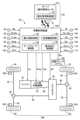
図1は、本発明の一実施例である隊列走行システム10の基本構成を説明する概略図である。図1において、隊列走行システム10は、隊列参加車両12と、隊列管理センタとしてのサーバ20と、を有して構成されている。このような隊列走行は、例えば高速道路等の自動車専用の道路を中心に行われる。隊列参加車両12は、複数の隊列参加車両12le、12fo-1、12fo-2、・・・12fo-nを含んでいる。隊列参加車両12leは、隊列の先頭車両である。隊列参加車両12fo-1、12fo-2、・・・12fo-nは、先頭車両12leに対して所定の車間距離ずつ隔てて1列で自動で追従走行する追従車両であり、追従車両の先頭側から順番に12fo-1、12fo-2、・・・12fo-nの符号が付してある。本実施例において、特に区別しない場合には、追従車両12fo-1、12fo-2、・・・12fo-nを追従車両12foと言い、先頭車両12le及び追従車両12foを隊列参加車両12と言う。サーバ20は、例えばパーソナルコンピュータ等の電子制御装置である。サーバ20は、例えば隊列参加車両12が所属する会社の本社や営業所等に設けられても良いし、又は、商用施設等が利用されても良い。Figure 1 is a schematic diagram illustrating the basic configuration of a
図2は、図1の隊列参加車両12として隊列に参加できる車両30の一例を説明する図であり、駆動系統の概略図と共に各種制御の為の制御機能及び制御系統の要部を示した図である。図2において、車両30は、隊列走行だけでなく単独走行も可能な通常の車両であり、車載の電子制御装置である車載制御装置130を備えている。車両30が隊列参加車両12として隊列に参加した場合には、各隊列参加車両12の車載制御装置130と、サーバ20とは、携帯電話網や無線LAN網、インターネット等の無線通信Rのネットワークを介して接続され(図1参照)、各種の情報を送受信することができる。又は、車両30が隊列参加車両12として隊列に参加した場合には、隊列参加車両12相互の無線通信例えば車車間通信等を介して接続されても良い。2 is a diagram for explaining an example of a
車載制御装置130及びサーバ20は、何れも、例えばCPU、RAM、ROM、入出力インターフェース等を備えた所謂マイクロコンピュータを含んで構成されており、CPUはRAMの一時記憶機能を利用しつつ予めROMに記憶されたプログラムに従って種々の信号処理を行うことにより各種制御を実行することができる。車載制御装置130及びサーバ20は、隊列参加車両12の各々を無線通信Rを介して接続し、隊列参加車両12による隊列走行を制御する車両用制御装置150である。The on-
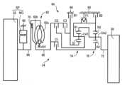
車両30は、前置エンジン後輪駆動方式(=FR方式)を基本とする前後輪駆動つまり4輪駆動のハイブリッド式電動車両である。車両30は、エンジン32と、エンジン32に連結されたHEV(Hybrid Electric Vehicle)用伝動装置34と、HEV用伝動装置34に連結されたトランスファ36と、を備えている。トランスファ36には、フロントプロペラシャフト38及びリヤプロペラシャフト46が各々連結されている。エンジン32及びHEV用伝動装置34からトランスファ36へ伝達された動力は、トランスファ36を介してフロントプロペラシャフト38及びリヤプロペラシャフト46に分配される。フロントプロペラシャフト38に分配された動力は、前輪側ディファレンシャルギヤ40及び左右の前輪ドライブシャフト42を介して左右の前輪44に伝達される。又、リヤプロペラシャフト46へ分配された動力は、後輪側ディファレンシャルギヤ48及び左右の後輪ドライブシャフト50を介して左右の後輪52に伝達される。後輪52は、2輪駆動(=2WD)走行及び4輪駆動(=4WD)走行の場合に共に駆動輪DWとなる主駆動輪である。前輪44は、2WD走行の時に従動輪となり且つ4WD走行の時に駆動輪DWとなる副駆動輪である。The
エンジン32は、ガソリンエンジンやディーゼルエンジン等の内燃機関であり、走行用の動力源SPとして用いられる。エンジン32は、スロットルアクチュエータや燃料噴射装置や点火装置等を有する図示しないエンジン制御機器が車載制御装置130によって制御されることにより、エンジン32の出力トルクであるエンジントルクTeが制御される。又、エンジン32は、例えば惰性走行時に駆動輪DW側から入力される動力により回転駆動される際に、フリクションによるエンジンブレーキを発生することができる。The
図3は、HEV用伝動装置34の具体例を説明する骨子図である。図3において、HEV用伝動装置34は、車体に取り付けられる非回転部材としてのトランスミッションケース60内に配設された回転機MGと、回転機MG及びエンジン32に、トルクコンバータ62を介して連結された変速部64と、を備えている。又、HEV用伝動装置34は、MG連結軸66を備えている。これらの回転機MG、トルクコンバータ62、変速部64は中心線に対して略対称的に構成されており、図3の骨子図では中心線の下側半分が省略されている。以下、トランスミッションケース60をケース60と言う。Figure 3 is a schematic diagram for explaining a specific example of a
回転機MGは、電力から機械的な動力を発生させる電動機としての機能及び機械的な動力から電力を発生させる発電機としての機能を有するモータジェネレータであって、例えば三相交流同期モータ等である。回転機MGは、車載制御装置130によって回転機MGのトルクであるMGトルクTmgや回転機MGの回転速度であるMG回転速度Nmgが制御される。回転機MGは、MG連結軸66に動力伝達可能に連結されている。つまり、回転機MGは、エンジン32とトルクコンバータ62との間の動力伝達経路に動力伝達可能に連結されている。回転機MGは走行用の動力源SPとして用いられ、エンジン32に替えて或いはエンジン32に加えて、走行用の動力を発生する。又、回転機MGは、エンジン32の動力や駆動輪DW側から入力される動力により回転駆動される際に、発電機として機能するように回生制御されることにより発電を行うと共に、駆動輪DWに連結されている場合には回生作動による回生ブレーキを発生する。回転機MGは、エンジン32のクランク軸に直接に或いは図示しないダンパー等を介して連結されている。回転機MGとエンジン32との間に動力伝達を接続遮断するエンジン断接クラッチ等が設けられても良い。The rotating machine MG is a motor generator that functions as an electric motor that generates mechanical power from electric power and as a generator that generates electric power from mechanical power, and is, for example, a three-phase AC synchronous motor. The rotating machine MG is controlled by the on-
トルクコンバータ62は、MG連結軸66を介して回転機MGに連結されたポンプ翼車62a、及び変速部64の入力軸68に連結されたタービン翼車62bを備えている。トルクコンバータ62は、ポンプ翼車62aとタービン翼車62bとを連結する公知のロックアップクラッチとしてのLUクラッチ70を備えている。The
変速部64は、トルクコンバータ62とトランスファ36との間の動力伝達経路に介在させられている。変速部64の出力軸72は、トランスファ36と連結されている。変速部64は、動力源SPの動力を駆動輪DWへ伝達する自動変速機である。The
変速部64は、例えば第1遊星歯車装置74及び第2遊星歯車装置76の複数組の遊星歯車装置と、ワンウェイクラッチF1を含む、クラッチC1、クラッチC2、クラッチC3、ブレーキB1、ブレーキB2の複数の係合装置とを備えている、公知の遊星歯車式の有段の自動変速機である。以下、クラッチC1、クラッチC2、クラッチC3、ブレーキB1、及びブレーキB2については、特に区別しない場合は単に係合装置CBという。The
係合装置CBは、油圧アクチュエータにより押圧される多板式或いは単板式のクラッチやブレーキ、油圧アクチュエータによって引き締められるバンドブレーキなどにより構成される、公知の油圧式の摩擦係合装置である。係合装置CBは、各々、車載制御装置130によって不図示の油圧制御回路から供給される係合装置CBの各油圧であるCB油圧PRcbが制御されることにより、それぞれのトルク容量であるCBトルクTcbが変化させられることで、係合状態や解放状態などの作動状態つまり制御状態が切り替えられる。The engagement device CB is a known hydraulic friction engagement device, such as a multi-plate or single-plate clutch or brake pressed by a hydraulic actuator, or a band brake tightened by a hydraulic actuator. The engagement devices CB are each controlled by the on-
変速部64は、第1遊星歯車装置74及び第2遊星歯車装置76の各回転要素が、直接的に或いは係合装置CBやワンウェイクラッチF1を介して間接的に、一部が互いに連結されたり、入力軸68、ケース60、或いは出力軸72に連結されている。第1遊星歯車装置74の各回転要素は、サンギヤS1、キャリアCA1、リングギヤR1であり、第2遊星歯車装置76の各回転要素は、サンギヤS2、キャリアCA2、リングギヤR2である。In the
変速部64は、係合装置CBのうちの何れかの係合装置が係合されることによって、変速比(ギヤ比ともいう)γ(=入力回転速度Ni/出力回転速度No)が異なる複数の変速段(ギヤ段ともいう)GSが選択的に形成される有段変速機である。変速部64は、車載制御装置130によって、ドライバー(=運転者)のアクセル操作や車速V等に応じて形成されるギヤ段GSが切り替えられる。入力回転速度Niは、入力軸68の回転速度であって、変速部64の入力回転速度であり、タービン翼車62bによって回転駆動されるタービン軸の回転速度であるタービン回転速度Ntと同値である。出力回転速度Noは、出力軸72の回転速度であって、変速部64の出力回転速度である。The
変速部64は、例えば図4の作動係合表に示すように、複数のギヤ段GSとして、第1速ギヤ段(図中の「1st」)~第4速ギヤ段(図中の「4th」)の前進4速が形成されると共に、後進ギヤ段(図中の「Rev」)が形成される。第1速ギヤ段の変速比γが最も大きく、高速走行が可能な第4速ギヤ段側であるハイ側のギヤ段GS程、変速比γが小さくなる。図4の作動係合表は、各ギヤ段GSと係合装置CBの各制御状態との関係をまとめたものである。図4では、「○」は係合を、「(○)」はエンジンブレーキ時や変速部64のコーストダウンシフト時に係合を、空欄は解放を、それぞれ表している。変速部64においてギヤ段GSが形成されると、変速部64は動力を伝達可能な状態つまり動力伝達可能状態とされる。変速部64のニュートラル状態(図中の「N」)は、変速部64が動力を伝達不能な状態つまり動力伝達不能状態であり、例えば係合装置CBが何れも解放状態とされて変速部64における動力伝達が遮断されることで実現される。As shown in the operation engagement table of FIG. 4, the
図2に戻り、トランスファ36は、例えば変速部64の出力軸72から伝達された回転をハイ(トランスファHi)及びロー(トランスファLo)の2段階で変速する副変速機、副変速機から出力されたトルクを所定の分配比でフロントプロペラシャフト38及びリヤプロペラシャフト46に分配する分配機構、フロントプロペラシャフト38及びリヤプロペラシャフト46の差動回転を制限するデフロック装置、後輪52のみを駆動する2輪駆動と全輪(前輪44、後輪52)を駆動する4輪駆動とを切り替える2駆-4駆切替装置等を備えている。副変速機のハイロー切替装置やデフロック装置、2駆-4駆切替装置は、車載制御装置130によって電気的に制御される。フロントプロペラシャフト38及びリヤプロペラシャフト46に対するトルクの分配比を電気的に制御できるトランスファ36を採用することもできる。Returning to FIG. 2, the
車両30は、更に、後述するオートクルーズ走行に関連して自動ブレーキシステム80を備えている。自動ブレーキシステム80は、前輪44及び後輪52に設けられた各ホイールブレーキ82fl、82fr、82rl、82rrのブレーキ力すなわちブレーキ油圧を、車載制御装置130からの指令に従って電気的に制御する。以下、ホイールブレーキ82fl、82fr、82rl、82rrについては、特に区別しない場合は単にホイールブレーキ82という。又、ホイールブレーキ82には、図示しないブレーキペダルが足踏み操作されることにより、ブレーキマスターシリンダを介してブレーキ油圧が供給されるようになっており、ホイールブレーキ82は、そのブレーキ油圧すなわちブレーキ操作力に応じたブレーキ力を機械的に発生する。The
車両30は、各種の制御を実行する制御装置として車載制御装置130を備えている。車載制御装置130は、必要に応じてエンジン制御用、MG制御用、油圧制御用等の複数の電子制御装置を備えて構成される。The
車載制御装置130には、車両30に備えられた各種センサ等(例えばエンジン回転速度センサ90、タービン回転速度センサ92、出力回転速度センサ94、MG回転速度センサ96、アクセル開度センサ98、スロットル弁開度センサ100、路面勾配センサ102、加速度センサ104、ギヤ段検出装置106、ミリ波レーダー等の車間距離センサ108、オートクルーズ設定装置110、隊列参加装置112など)による検出値に基づく各種信号等(例えばエンジン32の回転速度であるエンジン回転速度Ne、入力回転速度Niと同値であるタービン回転速度Nt、車速Vに対応する出力回転速度No、MG回転速度Nmg、アクセルペダル等のアクセル操作部材の操作量であって運転者の出力要求量を表すアクセル開度θacc、電子スロットル弁の開度であるスロットル弁開度θth、路面勾配Φ、車両30の前後加速度Gaや左右加速度Gb、変速部64のギヤ段GS、先行車両までの車間距離Dis、オートクルーズ設定情報Acrui、隊列参加情報Caraなど)が、それぞれ供給される。ギヤ段検出装置106は、例えば変速部64の係合装置CBの制御状態からギヤ段GSを検出できるが、入力回転速度Ni及び出力回転速度Noから変速比γを算出してギヤ段GSを特定しても良い。The on-
オートクルーズ設定装置110は、運転者の加減速操作を必要とすることなく予め定められた目標走行状態で走行するように、動力源SPを自動的に制御する自動運転として、定速走行及び追従走行を行うオートクルーズ走行を選択する装置である。すなわち、車両30は、アクセルペダル等による運転者の加減速操作に従ってエンジン32や回転機MGが制御される手動運転の他に、エンジン32や回転機MGを目標車速Vt等に従って自動的に制御するオートクルーズ走行が可能である。オートクルーズ設定装置110は、オートクルーズ走行を選択する他、目標車速Vtの設定、目標車速Vtの増減、先行車両に追従して走行する追従走行時の目標車間距離Dtの設定などを行う装置であり、例えばステアリングホイール等に配設され、目標車速Vt、目標車間距離Dt等が、オートクルーズ設定情報Acruiとして運転者により入力される。The auto-
隊列参加装置112は、先頭車両12le又は追従車両12foとして隊列に参加して走行する際に操作される装置であり、先頭車両12leとして参加するか追従車両12foとして参加するか、追従車両12foとして参加する場合の走行順などが、隊列参加情報Caraとして運転者により入力される。車両30を個別に識別できる識別番号や、搭載している変速部64のギヤ段GSの段数等を含む変速機情報を、隊列参加情報Caraとして運転者が入力しても良いが、初期設定等により車載制御装置130に予め登録されている場合は不要である。又、本実施例では、車両30とは別に、無段変速機や手動変速機を搭載している車両も、隊列参加車両12として隊列に参加することが可能であり、その無段変速機や手動変速機に関する変速機情報も、サーバ20と連携されるその車両の車載制御装置に隊列参加情報Caraとして設定される。隊列参加装置112は、例えばタッチ入力が可能なタッチパネル等を用いて構成されるが、運転者が所有するスマートフォン等の端末を用いて入力できるようにしても良い。又、隊列走行を行う日時や、隊列に参加する複数の隊列参加車両12、先頭車両12leか追従車両12foか、追従車両12foの走行順などの隊列実施情報を、隊列管理者等が予め決めてサーバ20に設定しておき、その隊列実施情報がサーバ20から対象の隊列参加車両12やその運転手等に伝達されるようにしても良い。The
車載制御装置130からは、車両30に備えられた各装置(例えばエンジン32、回転機MG、変速部64、トランスファ36、自動ブレーキシステム80など)を制御する為の各種指令信号(例えばエンジン32を制御する為のエンジン制御指令信号Se、回転機MGを制御する為のMG制御指令信号Smg、変速部64のギヤ段GSを切り替える為の変速制御指令信号Ssh、トランスファ36の動力伝達状態を切り替える為のトランスファ制御指令信号Stf、自動ブレーキシステム80を制御する為の自動ブレーキ制御指令信号Sbrなど)が、それぞれ出力される。The on-
又、車載制御装置130は、無線通信Rを介してサーバ20との間で各種情報Iを送受信する。例えば、車載制御装置130は、サーバ20から制御情報Icを受信すると共に、サーバ20へ車両情報Ivを送信する。制御情報Icは、例えば隊列走行の実行中であることを表す信号である隊列走行フラグの情報、前記隊列実施情報、変速部64のギヤ段GSを指示する情報、回生作動時の回転機MGの発電電力つまり回生量を指示する情報などを含んでいる。車両情報Ivは、例えば隊列参加車両12の各々を識別する車両識別情報、先頭車両12leを含む走行順情報、搭載している変速部64の種類やギヤ段数等に関する変速機情報、車両30の惰性走行時における前後加速度Gaすなわち減速度Grの情報、車間距離Disの情報などを含んでいる。減速度Grは、負値となる前後加速度Gaの絶対値を表している。尚、車載制御装置130は、サーバ20との間で送受信する各種情報Iを、無線通信Rを介して車両30とは別の隊列参加車両12との間で送受信しても良い。又、車載制御装置130が備える例えば不揮発性メモリなどには、エンジン32の出力特性、回転機MGの出力特性、車両単体重量WTvsなどの車両諸元の情報が記憶されていても良い。The
車載制御装置130は、車両30における各種制御を実現する為に、動力源制御手段すなわち動力源制御部132、変速機制御手段すなわち変速機制御部134、オートクルーズ制御手段すなわちオートクルーズ制御部136、及び隊列走行制御手段すなわち隊列走行制御部138を機能的に備えている。In order to realize various controls in the
動力源制御部132は、エンジン32及び回転機MGを協調して作動させてハイブリッド駆動制御等を実行するハイブリッド制御手段すなわちハイブリッド制御部である。動力源制御部132は、例えば駆動要求量マップにアクセル開度θacc及び車速Vを適用することで、運転者による車両30に対する駆動要求量を算出する。前記駆動要求量マップは、予め実験的に或いは設計的に求められて記憶された関係すなわち予め定められた関係である。前記駆動要求量は、車両30が出力する駆動量に対する要求値である。前記駆動量は、例えば駆動輪DWにおける駆動力Frや駆動トルクTr等であり、前記駆動要求量は、例えば駆動輪DWにおける要求駆動力Frdemや要求駆動トルクTrdem等である。動力源制御部132は、伝達損失、補機負荷、変速部64の変速比γ等を考慮して、例えば要求駆動トルクTrdemを実現する為に必要な動力源SPのトルクが得られるように、エンジン32を制御するエンジン制御指令信号Seを出力すると共に、回転機MGを制御するMG制御指令信号Smgを出力する。The power
HEV用伝動装置34は、例えば回転機MGとエンジン32との間の動力伝達経路にそれらの間での動力伝達を遮断するエンジン断接用のクラッチを備えていても良い。動力源制御部132は、前記エンジン断接用のクラッチが備えられている場合には、そのクラッチの解放状態且つエンジン32の運転停止状態において、回転機MGのみを動力源SPに用いて走行するモータ走行つまりBEV(Battery Electric Vehicle)走行を行うことができる。例えば、動力源制御部132は、回転機MGの出力のみで要求駆動トルクTrdemを賄える場合には、駆動モードとしてBEV駆動モードを成立させる。BEV駆動モードは、BEV走行(=電動走行)が可能な電動駆動モードである。一方で、動力源制御部132は、少なくともエンジン32の出力を用いないと要求駆動トルクTrdemを賄えない場合には、駆動モードとしてエンジン駆動モードつまりHEV駆動モードを成立させる。HEV駆動モードは、前記エンジン断接用のクラッチの係合状態において、少なくともエンジン32を動力源SPに用いて走行するエンジン走行つまりハイブリッド走行(=HEV走行)が可能なハイブリッド駆動モードである。他方で、動力源制御部132は、回転機MGの出力のみで要求駆動トルクTrdemを賄える場合であっても、エンジン32等の暖機が必要な場合などには、駆動モードとしてHEV駆動モードを成立させる。The
変速機制御部134は、例えば予め定められた関係である変速マップを用いて変速部64の変速判断を行い、必要に応じて変速部64の変速制御を実行する変速制御指令信号Sshを出力する。図5は、変速部64として図3の4段変速機を備えている場合の変速マップの一例である。図5の変速マップは、例えば車速V及び要求駆動トルクTrdemを変数とする二次元座標上に、変速部64の変速が判断される為の変速線を有する所定の関係である。前記変速線は、アップシフトが判断される為のアップシフト線(実線参照)、及びダウンシフトが判断される為のダウンシフト線(破線参照)である。図中の数字「1」~「4」は、第1速ギヤ段~第4速ギヤ段を示している。図5の変速マップでは、車速Vに替えて出力回転速度Noなどを用いても良いし、又、要求駆動トルクTrdemに替えて要求駆動力Frdemやアクセル開度θaccやスロットル弁開度θthなどを用いても良い。The
オートクルーズ制御部136は、自動運転としてオートクルーズ走行を実行する。オートクルーズ走行は、運転者の加減速操作を必要とすることなく自律走行するものであり、オートクルーズ設定装置110により設定された目標車速Vtにて定速走行する定速走行制御、及びオートクルーズ設定装置110により設定された目標車間距離Dtを保持しつつ追従走行する追従走行制御を実行する。オートクルーズ制御部136は、定速走行制御では、目標車速Vtにて走行するのに必要な要求駆動トルクTrdemを算出すると共に、伝達損失、補機負荷、変速部64の変速比γ等を考慮して、要求駆動トルクTrdemを実現する為に必要な動力源SPのトルクが得られるように、エンジン32を制御するエンジン制御指令信号Seを出力すると共に、回転機MGを制御するMG制御指令信号Smgを出力する。ここでの要求駆動トルクTrdemは、例えば目標車速Vtと車速Vとの差などに基づいてフィードバック制御やフィードフォワード制御等によって求められる。一方で、オートクルーズ制御部136は、先行車両に対して目標車間距離Dtを保持しつつ追従走行する追従走行制御では、車間距離Disが目標車間距離Dtとなる状態で追従走行するのに必要な要求駆動トルクTrdemを算出し、その要求駆動トルクTrdemが得られるようにエンジントルクTeやMGトルクTmgを制御する。目標車間距離Dtは、例えば車速V等に応じて可変設定される。又、オートクルーズ制御部136は、先行車両の減速時など要求駆動トルクTrdemが負(マイナス)の場合は、エンジン32によるエンジンブレーキや回転機MGによる回生ブレーキを発生させたり、必要な場合は自動ブレーキシステム80によって制御されるホイールブレーキ82のブレーキ力と合わせて負の要求駆動トルクTrdemが得られるようにする。本実施例では、エンジンブレーキや回生ブレーキなどによって発生させられる負の駆動トルクTrを被駆動トルクTrrと称する。尚、変速機制御部134は、このオートクルーズ走行時においても、図5の変速マップ等の変速条件に従って変速部64のギヤ段GSを切り替える変速制御を実行する。The auto-
隊列走行制御部138は、車両30が隊列参加車両12として隊列走行に参加する場合の隊列走行制御に関与するものであり、例えば隊列参加情報Caraをサーバ20に送信して隊列走行に参加すると共に、オートクルーズ制御部136によるオートクルーズ走行を行う。隊列走行制御部138は、追従車両12foとして隊列走行に参加した場合は、追従走行制御により先行車両に対して所定の車間距離Dis例えば目標車間距離Dtを保持して追従走行する。尚、車両30が、運転者の加減速操作に加えて操舵操作を必要とすることなく自律走行する自動運転走行、又は無人走行が可能である場合には、隊列走行制御部138は、自動運転走行又は無人走行にて隊列走行に参加しても良い。The platoon
ここで、サーバ20は、隊列管理制御手段すなわち隊列管理制御部22を機能的に備えている。隊列管理制御部22は、隊列走行の実行中であるか否かを判断する。例えば、隊列管理制御部22は、隊列参加車両12との間で送受信した各種情報Iに基づいて、隊列走行の実行中であるか否かを判断する。隊列管理制御部22は、隊列走行の実行中であると判定した場合には、隊列参加車両12の各々から隊列走行の管理や駆動量の管理等に必要な車両情報Ivを取得すると共に、隊列参加車両12の各々へ隊列走行制御や駆動量制御等に必要な制御情報Icを送信する。Here, the
ところで、目標車速Vt及び/又は目標車間距離Dtを保持するように、加速走行や惰性走行などを繰り返して隊列走行を実行する場合、惰性走行時に各隊列参加車両12における現在の車両状態の違いによって減速度Grが異なると、車間距離Disが変動し易くなる。又は、惰性走行時に隊列参加車両12における減速度Grが略同じであったとしても、各隊列参加車両12の走行抵抗の違いにより車間距離Disが変動する可能性がある。車間距離Disの変動は、目標車間距離Dtを保持する制御によって抑制される。しかしながら、目標車間距離Dtを保持する制御は車間距離Disの変動が発生してからとなるので、惰性走行となる前から、惰性走行に切り替わったときに車間距離Disが元々変動し難い車両状態にしておくことが考えられる。但し、車間距離Disが長くなる方に変動するのであれば、運転者に安心感を与えられるので、車間距離Disが短くなる方に変動しないようにすることが望ましい。When platooning is performed by repeatedly accelerating and coasting to maintain the target vehicle speed Vt and/or the target inter-vehicle distance Dt, if the deceleration Gr differs due to differences in the current vehicle state of each
そこで、車両用制御装置150は、隊列走行の実行中には、隊列参加車両12の並び順を先頭車両12leから順に減速度Grの推定値が大きくなる並び順とするように、隊列参加車両12の各々における被駆動トルクTrrを制御する、被駆動トルク調整制御CTrrを行う。つまり、車両用制御装置150は、隊列走行の実行中には、惰性走行となる前から、惰性走行に備えて被駆動トルク調整制御CTrrを行う。本実施例では、減速度Grの推定値を推定減速度Greと言う。Therefore, while platooning is being performed, the
具体的には、車両用制御装置150は、隊列参加車両12毎に現在の車両状態において単独で惰性走行したときの被駆動トルクTrrに基づく推定減速度Greを算出する。例えば、エンジン32を搭載した隊列参加車両12では、車載制御装置130は、現在のエンジン回転速度Neに基づいて惰行走行となった場合のエンジンブレーキによって得られる被駆動トルクTrrを算出する。又は、回転機MGを搭載した隊列参加車両12では、車載制御装置130は、現在の車両状態において惰行走行となった場合の回生ブレーキによって得られる被駆動トルクTrrを算出する。エンジン32及び回転機MGを搭載した隊列参加車両12では、車載制御装置130は、エンジンブレーキによって得られる被駆動トルクTrrに回生ブレーキによって得られる被駆動トルクTrrを加えた合計の被駆動トルクTrrを算出しても良い。車載制御装置130は、被駆動トルクTrrと、現在の車両状態において単独で惰性走行したときの走行抵抗RLと、に基づいて推定減速度Greを算出する。走行抵抗RLは、例えば平坦路を定常走行する場合には、車速Vの関数である空気抵抗Faと、車両単体重量WTvsに搭乗者の重量などを加えた合計の重量である車両重量WTvの関数であるころがり抵抗Frlと、の合算値(=Fa+Frl)[N]である。車載制御装置130は、例えば予め定められた関係である走行抵抗マップに現在の車速V及び車両重量WTvを適用することで、現在の車両状態において単独で惰性走行したときの走行抵抗RLを算出する。このように、車両用制御装置150は、隊列参加車両12毎の被駆動トルクTrrに基づく推定減速度Greを車両重量WTvに基づいて算出する。Specifically, the
車両用制御装置150は、隊列参加車両12毎の被駆動トルクTrrに基づく推定減速度Greを、隊列走行の開始後つまり隊列走行の実行中に算出しても良いし、隊列走行の実行前に算出しても良い。推定減速度Greが隊列走行の実行前に算出されることで、隊列走行を開始する際に推定減速度Greの情報を利用して隊列を組むことができる。The
被駆動トルク調整制御CTrrは、隊列走行の実行中に行われ、隊列走行の非実行中には行われない。その為、車両用制御装置150は、隊列走行が開始されているか否かを判定する。The driven torque adjustment control CTrr is performed when platooning is in progress, but is not performed when platooning is not in progress. Therefore, the
車両用制御装置150は、隊列走行が開始されていると判定した場合には、つまり隊列走行の実行中には、隊列参加車両12毎に現在の車両状態において単独で惰性走行したときの被駆動トルクTrrに基づく推定減速度Greの情報を取得し、被駆動トルク調整制御CTrrを行う。When the
尚、隊列参加車両12の何れかの車両において、推定減速度Greが算出できない場合がある。この場合には、被駆動トルク調整制御CTrrが行われ得ない。その為、車両用制御装置150は、隊列走行が開始されていると判定した場合には、隊列参加車両12毎の被駆動トルクTrrに基づく推定減速度Greを取得可能つまり把握可能であるか否かを判定する。車両用制御装置150は、推定減速度Greを把握可能であると判定した場合に、被駆動トルク調整制御CTrrを行う。In addition, there may be cases where the estimated deceleration Gre cannot be calculated for any of the
車両用制御装置150は、被駆動トルク調整制御CTrrでは、現在の車両状態において被駆動トルクTrrの調整によって推定減速度Greを変更可能な隊列参加車両12を把握すると共に、推定減速度Greの変更可能範囲を考慮しつつ隊列参加車両12の前後する車両同士の被駆動トルクTrrによる推定減速度Greの差が均等な隊列が形成可能となるように、被駆動トルクTrrを調整するつまり変更する。そして、車両用制御装置150は、決定した被駆動トルクTrrによる推定減速度Greを基にして、隊列参加車両12の並び順を決定する。車両用制御装置150は、推定減速度Greが最も小さい車両を先頭車両12leとし、後方に行くに従って推定減速度Greの大きい車両となるように隊列を形成する。In the driven torque adjustment control CTrr, the
エンジン32と変速部64とを搭載した隊列参加車両12では、車載制御装置130は、エンジン32によるエンジンブレーキによって得られる被駆動トルクTrrを、変速部64の変速比γを変更することで制御する。つまり、車載制御装置130は、変速部64の変速比γを変更することで被駆動トルクTrrを調整し、推定減速度Greを変更することができる。変速部64として図3の4段変速機を備えている場合には、車載制御装置130は、エンジン32による被駆動トルクTrrを調整することで、推定減速度Greを非連続な4段階に調整できる。又は、変速部64として無段変速機を備えている場合には、車載制御装置130は、エンジン32による被駆動トルクTrrを調整することで、連続的な推定減速度Greを設定できる。In the
回転機MGを搭載した隊列参加車両12では、車載制御装置130は、回転機MGによる回生ブレーキによって得られる被駆動トルクTrrを、回転機MGの回生量を変更することで制御する。つまり、車載制御装置130は、回転機MGの回生量を変更することで被駆動トルクTrrを調整し、推定減速度Greを変更することができる。動力源SPとして回転機MGを備えている場合には、車載制御装置130は、回転機MGによる被駆動トルクTrrを調整することで、連続的な推定減速度Greを設定できる。In a platoon-participating
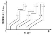
図6は、隊列走行中において惰性走行したときに備えた減速度設定の一例を示す図である。図6において、点aは、先頭車両12leが現在の車両状態にて設定可能な推定減速度Greを示している。実線bの範囲は、追従車両12fo-1が現在の車両状態にて設定可能な推定減速度Greの範囲を示している。実線bの範囲は、例えば無段変速機の変速可能範囲、又は、回転機MGの回生量の変更可能範囲に対応している。点c及び点dは、各々、追従車両12fo-2が現在の車両状態にて設定可能な推定減速度Greを示している。点dは、点cに対して有段変速機がダウンシフトされた状態である。追従車両12fo-2が設定可能な推定減速度Greのうちで、最も小さい推定減速度Gre(点c参照)を設定しても、先行する先頭車両12leや追従車両12fo-1の推定減速度Greを下回らないので、追従車両12fo-2の推定減速度Greとして、最も小さい推定減速度Greに対応する「減速度2」を選択する。先頭車両12leの推定減速度Greとして設定される「減速度1」と、追従車両12fo-2の推定減速度Greとして設定される「減速度2」と、を基にして、追従車両12fo-1の推定減速度Greを設定できる。図6の実施例では、追従車両12fo-1の推定減速度Greとして、先頭車両12leと追従車両12fo-2との中間の推定減速度Gre(点e参照)となる「減速度1.5」を設定する。上述した被駆動トルク調整制御CTrrを行うことで、惰性走行時に車間距離Disが短くなることを抑制又は防止することができる。尚、図6における隊列は、隊列走行の開始に際して、各車両で設定可能な推定減速度Greが算出され、隊列参加車両12の並び順及び推定減速度Greが決定された後に、それらの並び順及び推定減速度Greに基づいて被駆動トルクTrrが調整されつつ形成されたものである。又は、図6における隊列は、隊列走行中に決定された並び順及び推定減速度Greに基づいて、被駆動トルクTrrが調整されつつ隊列参加車両12の並び順が入れ替えられたものである。又は、図6における隊列は、隊列走行中に決定された並び順及び推定減速度Greに基づいて、形成されている並び順のままで被駆動トルクTrrが調整されたものである。Figure 6 is a diagram showing an example of deceleration settings in preparation for coasting during platooning. In Figure 6, point a indicates the estimated deceleration Gre that can be set for the leading vehicle 12le in its current vehicle state. The range of solid line b indicates the range of estimated deceleration Gre that can be set for the following vehicle 12fo-1 in its current vehicle state. The range of solid line b corresponds to, for example, the range in which the continuously variable transmission can be changed, or the range in which the regeneration amount of the rotary machine MG can be changed. Points c and d each indicate the estimated deceleration Gre that can be set for the following vehicle 12fo-2 in its current vehicle state. Point d is a state in which the stepped transmission has been downshifted relative to point c. Even if the smallest estimated deceleration Gre (see point c) is set among the estimated decelerations Gre that can be set by the following vehicle 12fo-2, it will not fall below the estimated decelerations Gre of the preceding leading vehicle 12le and the following vehicle 12fo-1, so "
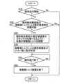
図7は、車両用制御装置150の制御作動の要部を説明するフローチャートであって、隊列走行中の惰性走行時に隊列参加車両12間の車間距離Disが短くなることを抑制する為の制御作動を説明するフローチャートであり、例えば繰り返し実行される。Figure 7 is a flowchart explaining the main control operations of the
図7において、フローチャートの各ステップは車両用制御装置150の機能に対応している。ステップ(以下、ステップを省略する)S10において、隊列走行が開始されているか否かが判定される。このS10の判断が否定される場合は本ルーチンが終了させられる。このS10の判断が肯定される場合はS20において、隊列参加車両12毎の被駆動トルクTrrによる推定減速度Greを把握可能であるか否かが判定される。このS20の判断が否定される場合は本ルーチンが終了させられる。このS20の判断が肯定される場合はS30において、隊列参加車両12の推定減速度Greのステップが均等になるように、各車の被駆動トルクTrrが調整される。次いで、S40において、被駆動トルクTrrによる推定減速度Greが小さい順に、つまり推定減速度Greが後方に行くに従って大きくなるように、隊列が形成される。次いで、S50において、隊列走行が終了したか否かが判定される。このS50の判断が否定される場合はこのS50が繰り返し実行させられる。このS50の判断が肯定される場合はS60において、被駆動トルク調整制御CTrrが終了させられる。7, each step of the flowchart corresponds to a function of the
上述のように、本実施例によれば、隊列走行の実行中には、隊列参加車両12毎に現在の車両状態において単独で惰性走行したときの被駆動トルクTrrに基づく推定減速度Greの情報が取得され、隊列参加車両12の並び順を先頭車両12leから順に推定減速度Greが大きくなる並び順とするように、隊列参加車両12の各々における被駆動トルクTrrが制御されるので、先行車両に対して追従車両12foの方が空気抵抗が小さくされたとしても実際の減速度Grが小さくなってしまうことが抑制される。よって、隊列走行中の惰性走行時に隊列参加車両12間の車間距離Disが短くなることを抑制することができる。As described above, according to this embodiment, while platooning is being performed, information on the estimated deceleration Gre based on the driven torque Trr when each platooning
また、本実施例によれば、エンジン32と変速部64とを備えた隊列参加車両12では、エンジンブレーキによって得られる被駆動トルクTrrが変速部64の変速比γを変更することで制御されるので、隊列参加車両12の並び順を先頭車両12leから順に推定減速度Greが大きくなる並び順とするように、被駆動トルクTrrが制御され易くされる。In addition, according to this embodiment, in a
また、本実施例によれば、回転機MGを備えた隊列参加車両12では、回生ブレーキによって得られる被駆動トルクTrrが回転機MGの回生量を変更することで制御されるので、隊列参加車両12の並び順を先頭車両12leから順に推定減速度Greが大きくなる並び順とするように、被駆動トルクTrrが制御され易くされる。In addition, according to this embodiment, in a
また、本実施例によれば、隊列参加車両12毎の被駆動トルクTrrに基づく推定減速度Greが隊列走行の実行前に算出されるので、隊列走行を開始する際に被駆動トルクTrrの変更可能範囲を考慮して隊列を組むことができる。これにより、隊列参加車両12の並び順を先頭車両12leから順に推定減速度Greが大きくなる並び順とするように、被駆動トルクTrrが制御され易くされる。In addition, according to this embodiment, the estimated deceleration Gre based on the driven torque Trr of each
また、本実施例によれば、隊列参加車両12毎の被駆動トルクTrrに基づく推定減速度Greが車両重量WTvに基づいて算出されるので、隊列参加車両12毎の推定減速度Greが搭乗者の重量に対応して適切に算出される。In addition, according to this embodiment, the estimated deceleration Gre based on the driven torque Trr of each
次に、本発明の他の実施例を説明する。なお、以下の説明において実施例相互に共通する部分には同一の符号を付して説明を省略する。Next, other embodiments of the present invention will be described. In the following description, parts common to the embodiments will be given the same reference numerals and will not be described.
前述の実施例1では、単独で惰性走行したときの走行抵抗RLを反映した推定減速度Greを算出した。走行抵抗RLに含まれる空気抵抗Faは、先頭車両12leから順に小さくなる。その為、追従車両12foでは、空気抵抗Faが小さくされる分だけ単独走行時よりも推定減速度Greが小さくされる。In the above-described first embodiment, the estimated deceleration Gre was calculated to reflect the running resistance RL when the vehicle coasts alone. The air resistance Fa included in the running resistance RL decreases in order from the leading vehicle 12le. Therefore, in the following vehicle 12fo, the estimated deceleration Gre is made smaller than when the vehicle coasts alone by the amount that the air resistance Fa is reduced.
そこで、本実施例では、車両用制御装置150は、隊列参加車両12の並び順による空気抵抗Faの差を加味した推定減速度Greを算出する。車両用制御装置150は、隊列走行の実行中には、隊列参加車両12の並び順による空気抵抗Faの差を加味した推定減速度Greの情報を取得し、被駆動トルク調整制御CTrrを行う。Therefore, in this embodiment, the
図8は、隊列走行中において惰性走行したときに備えた、空気抵抗Faを考慮した減速度設定の一例を示す図である。図8において、点a、実線bの範囲、点c、点d、及び点eは、各々、図6における点a、実線bの範囲、点c、点d、及び点eと同じである。先頭車両12leの空気抵抗Faが最も大きく、追従車両12fo-1、追従車両12fo-2の順に空気抵抗Faが小さくされる。先頭車両12leの空気抵抗Faは、単独で惰性走行したときの空気抵抗Faと同じであるので、先頭車両12leにおいて設定される推定減速度Greは、点aに示した「減速度1」のままである。追従車両12fo-1の空気抵抗Faは、単独で惰性走行したときの空気抵抗Faよりも小さくされるので、追従車両12fo-1において設定可能な推定減速度Greは、破線fに示されるように、空気抵抗Faが小さくされる分だけ実線bの範囲よりも全体的に小さくされた範囲とされる。又、「減速度1.5」として設定した推定減速度Greも、空気抵抗Faが小さくされる分だけ小さくされる(点g参照)。追従車両12fo-2の空気抵抗Faは、追従車両12fo-1に対して、単独で惰性走行したときの空気抵抗Faよりも更に小さくされるので、追従車両12fo-2において設定可能な推定減速度Greは、点h及び点iに示されるように、各々、空気抵抗Faが小さくされる分だけ点c及び点dよりも小さくされる。先頭車両12leの推定減速度Greを点aで設定し、追従車両12fo-1の推定減速度Greを点gで設定し、追従車両12fo-2の推定減速度Greを点hで設定しても、推定減速度Greに一定の差を持たせられるが、点a、点e、点cで設定する場合に比べて、差が小さくされる。そこで、追従車両12fo-2において、有段変速機をダウンシフトしギヤ段を変更することで追従車両12fo-2の推定減速度Greを点iで設定する。又、追従車両12fo-1の推定減速度Greとして、点aと点iとの中間の推定減速度Gre(点j参照)を設定する。これにより、点a、点e、点cで設定する場合の推定減速度Greの差と同等の状態ができる。図8の実施例では、追従車両12fo-2において推定減速度Greを変更しなくても、先頭車両12leから後方に行くに従って大きくなる推定減速度Greを設定できた。先頭車両12leから後方に行くに従って大きくなる推定減速度Greを設定できない場合には、何れかの車両の推定減速度Greを変更したり、隊列参加車両12の並び順を入れ替えることによって、先頭車両12leから後方に行くに従って大きくなる推定減速度Greとなるように再度制御する。尚、空気抵抗Faを考慮した推定減速度Greの算出は、隊列走行の開始前に行われても良いし、隊列走行中に想定した推定減速度Greとの差を見ることで被駆動トルク調整制御CTrrに適宜適用されても良い。想定した推定減速度Greとは、単独で惰性走行したときの空気抵抗Faを用いて算出した推定減速度Greである。Figure 8 is a diagram showing an example of deceleration setting that takes into account air resistance Fa in preparation for coasting during platooning. In Figure 8, point a, the range of solid line b, points c, d, and e are the same as point a, the range of solid line b, points c, d, and e in Figure 6, respectively. The air resistance Fa of the leading vehicle 12le is the largest, followed by the following vehicles 12fo-1 and 12fo-2 in that order. Since the air resistance Fa of the leading vehicle 12le is the same as the air resistance Fa when coasting alone, the estimated deceleration Gre set for the leading vehicle 12le remains at "
上述のように、本実施例によれば、隊列参加車両12の並び順による空気抵抗Faの差を加味した推定減速度Greの情報が取得されるので、先行車両に対して追従車両12foの方が空気抵抗が小さくされたとしても実際の減速度Grが小さくなってしまうことが一層抑制されるか又は回避される。As described above, according to this embodiment, information on the estimated deceleration Gre is obtained that takes into account the difference in air resistance Fa due to the arrangement order of the
前述の実施例1、2において、隊列走行中に惰性走行したときに、被駆動トルク調整制御CTrrが行われていることによって何れかの隊列参加車両12間の車間距離Disが目標車間距離Dtよりも十分に長くなる場合がある。このような場合、被駆動トルク調整制御CTrrを行う必要はない。In the above-mentioned first and second embodiments, when coasting during platooning, the driven torque adjustment control CTrr may be performed, causing the inter-vehicle distance Dis between any of the platoon-participating
そこで、本実施例では、車両用制御装置150は、被駆動トルクTrrの制御つまり被駆動トルク調整制御CTrrによって何れかの隊列参加車両12間の車間距離Disが所定の車間距離Dis例えば目標車間距離Dtよりも長い所定の終了判定閾値Dendを超えた場合には、被駆動トルク調整制御CTrrを終了する。所定の終了判定閾値Dendは、例えば惰性走行中に車間距離Disが目標車間距離Dtに対して十分に長くなったと判断する為の予め定められた閾値である。Therefore, in this embodiment, the
図9は、車両用制御装置150の制御作動の要部を説明するフローチャートであって、隊列走行中の惰性走行時に隊列参加車両12間の車間距離Disが短くなることを抑制する為の制御作動を説明するフローチャートであり、例えば繰り返し実行される。図9は、図7のフローチャートとは別の実施例である。図9では、図7と異なる点が主に記載されている。Figure 9 is a flowchart explaining the main control operations of the
図9において、フローチャートの各ステップは車両用制御装置150の機能に対応している。前記S40に次いで、S45において、惰性走行中であるか否かが判定される。このS45の判断が肯定される場合はS48において、車間距離Disが所定の終了判定閾値Dendを超えたか否かが判定される。このS48の判断が否定される場合は上記S45が実行させられる。上記S45の判断が否定される場合は前記S50が実行させられる。前記S50の判断が否定される場合は上記S45が実行させられる。上記S48の判断が肯定される場合は、又は、前記S50の判断が肯定される場合は、前記S60が実行させられる。In FIG. 9, each step of the flowchart corresponds to a function of the
上述のように、本実施例によれば、被駆動トルク調整制御CTrrによって何れかの隊列参加車両12間の車間距離Disが所定の終了判定閾値Dendを超えた場合には、被駆動トルク調整制御CTrrが終了させられるので、隊列参加車両12間の車間距離Disが短くなることが回避される状況となれば、それ以上車間距離Disが長くなることが抑制される。As described above, according to this embodiment, when the driven torque adjustment control CTrr causes the inter-vehicle distance Dis between any of the
以上、本発明の実施例を図面に基づいて詳細に説明したが、本発明はその他の態様においても適用される。The above describes in detail an embodiment of the present invention based on the drawings, but the present invention can also be applied in other aspects.
例えば、前述の実施例2や実施例3は、前述の実施例1に対して、組み合わされて実行されても良い。For example, the above-mentioned Example 2 and Example 3 may be implemented in combination with the above-mentioned Example 1.
また、前述の実施例において、図7、図9のフローチャートの各ステップの一部又は全部は、車両用制御装置150が含むサーバ20によって実行されても良い。又、図7、図9のフローチャートの各ステップの一部又は全部は、車両用制御装置150が含む車載制御装置130によって実行されても良い。In the above-described embodiment, some or all of the steps in the flowcharts in FIG. 7 and FIG. 9 may be executed by the
尚、上述したのはあくまでも一実施形態であり、本発明は当業者の知識に基づいて種々の変更、改良を加えた態様で実施することができる。The above is merely one embodiment, and the present invention can be implemented in various forms with various modifications and improvements based on the knowledge of those skilled in the art.
12:隊列参加車両
12le:先頭車両(隊列参加車両)
12fo(12fo-1、12fo-2、12fo-n):追従車両(隊列参加車両)
20:サーバ(車両用制御装置)
32:エンジン(動力源)
44:前輪(駆動輪)
52:後輪(駆動輪)
64:変速部(自動変速機)
130:車載制御装置(車両用制御装置)
150:車両用制御装置
DW:駆動輪
MG:回転機(動力源)
R:無線通信
SP:動力源12: Platooning vehicle 12le: Leading vehicle (platooning vehicle)
12fo (12fo-1, 12fo-2, 12fo-n): Following vehicles (vehicles participating in the platoon)
20: Server (vehicle control device)
32: Engine (power source)
44: Front wheels (drive wheels)
52: Rear wheels (drive wheels)
64: Transmission section (automatic transmission)
130: Vehicle-mounted control device (vehicle control device)
150: Vehicle control device DW: Drive wheel MG: Rotating machine (power source)
R: Wireless communication SP: Power source
Claims (7)
Translated fromJapanese前記隊列走行の実行中には、前記隊列参加車両毎に現在の車両状態において単独で惰性走行したときの被駆動トルクに基づく減速度の推定値の情報を取得し、前記隊列参加車両の並び順を前記先頭車両から順に前記減速度の推定値が大きくなる並び順とするように、前記隊列参加車両の各々における前記被駆動トルクを制御するものであり、
動力源として回転機を備えた前記隊列参加車両では、前記回転機の回生作動による回生ブレーキによって得られる前記被駆動トルクを、前記回転機の回生量を変更することで制御することを特徴とする車両用制御装置。 A vehicle control device that connects each of platoon participating vehicles, including a lead vehicle and a follow vehicle that automatically follows the lead vehicle in a single file at a predetermined vehicle distance from the lead vehicle, via wireless communication and controls the platoon traveling of the platoon participating vehicles,
During the platoon traveling, information on an estimated value of deceleration based on a driven torque when the platoon participating vehicle coasts alone in a current vehicle state is acquired for each of the platoon participating vehicles, and the driven torque of each of the platoon participating vehicles is controlled so that the platoon participating vehicles are arranged in an order of increasing estimated value of deceleration starting from the leading vehicle,
A vehicle control device characterized in that, in a vehicle participating in a platoon equipped with a rotating machine as a power source, the driven torque obtained by regenerative braking due to the regenerative operation of the rotating machine is controlled by changing the amount of regeneration of the rotating machine .
前記隊列走行の実行中には、前記隊列参加車両毎に現在の車両状態において単独で惰性走行したときの被駆動トルクに基づく減速度の推定値の情報を取得し、前記隊列参加車両の並び順を前記先頭車両から順に前記減速度の推定値が大きくなる並び順とするように、前記隊列参加車両の各々における前記被駆動トルクを制御するものであり、
動力源としてのエンジンと、前記エンジンの動力を駆動輪へ伝達する自動変速機と、を備えた前記隊列参加車両では、前記エンジンのフリクションによるエンジンブレーキによって得られる前記被駆動トルクを、前記自動変速機の変速比を変更することで制御することを特徴とする車両用制御装置。A vehicle control device that connects each of platoon participating vehicles, including a lead vehicle and a follow vehicle that automatically follows the lead vehicle in a single file at a predetermined vehicle distance from the lead vehicle, via wireless communication and controls the platoon traveling of the platoon participating vehicles,
During the platoon traveling, information on an estimated value of deceleration based on a driven torque when the platoon participating vehicle coasts alone in a current vehicle state is acquired for each of the platoon participating vehicles, and the driven torque of each of the platoon participating vehicles is controlled so that the platoon participating vehicles are arranged in an order of increasing estimated value of deceleration starting from the leading vehicle,
A vehicle control device for a platooning vehicle equipped with an engine as a power source and an automatic transmission that transmits the power of the engine to the drivewheels , characterized in that the driven torque obtained by engine braking due to friction of the engine is controlled by changing the gear ratio of the automatic transmission.
Priority Applications (3)
| Application Number | Priority Date | Filing Date | Title |
|---|---|---|---|
| JP2022054458AJP7626091B2 (en) | 2022-03-29 | 2022-03-29 | Vehicle control device |
| US18/188,570US12296825B2 (en) | 2022-03-29 | 2023-03-23 | Vehicle control device |
| CN202310310243.4ACN116890827A (en) | 2022-03-29 | 2023-03-28 | Control device for vehicle |
Applications Claiming Priority (1)
| Application Number | Priority Date | Filing Date | Title |
|---|---|---|---|
| JP2022054458AJP7626091B2 (en) | 2022-03-29 | 2022-03-29 | Vehicle control device |
Publications (2)
| Publication Number | Publication Date |
|---|---|
| JP2023146977A JP2023146977A (en) | 2023-10-12 |
| JP7626091B2true JP7626091B2 (en) | 2025-02-04 |
Family
ID=88195470
Family Applications (1)
| Application Number | Title | Priority Date | Filing Date |
|---|---|---|---|
| JP2022054458AActiveJP7626091B2 (en) | 2022-03-29 | 2022-03-29 | Vehicle control device |
Country Status (3)
| Country | Link |
|---|---|
| US (1) | US12296825B2 (en) |
| JP (1) | JP7626091B2 (en) |
| CN (1) | CN116890827A (en) |
Families Citing this family (1)
| Publication number | Priority date | Publication date | Assignee | Title |
|---|---|---|---|---|
| US20240270246A1 (en)* | 2023-02-09 | 2024-08-15 | Hl Mando Corporation | Driver assistance apparatus and driver assistance method |
Citations (3)
| Publication number | Priority date | Publication date | Assignee | Title |
|---|---|---|---|---|
| JP2012108797A (en) | 2010-11-18 | 2012-06-07 | Toyota Motor Corp | Vehicle control device |
| US10017039B1 (en) | 2017-07-20 | 2018-07-10 | Bendix Commercial Vehicle Systems Llc | Vehicle platooning with a hybrid electric vehicle system |
| JP2019101677A (en) | 2017-11-30 | 2019-06-24 | トヨタ自動車株式会社 | Vehicle platooning system |
Family Cites Families (15)
| Publication number | Priority date | Publication date | Assignee | Title |
|---|---|---|---|---|
| JPH101036A (en)* | 1996-06-17 | 1998-01-06 | Hino Motors Ltd | Auto-cruise device having inter-vehicle distance retaining function |
| US6167357A (en)* | 1998-04-23 | 2000-12-26 | Cummins Engine Company, Inc. | Recursive vehicle mass estimation |
| DE10009521A1 (en)* | 2000-02-29 | 2001-08-30 | Mannesmann Sachs Ag | Electrical system has parts of electrical component(s) and/or controler(s) to be cooled connected into conditioning system coolant circuit with e.g. compressor, condenser, evaporator |
| WO2014145918A1 (en)* | 2013-03-15 | 2014-09-18 | Peloton Technology, Inc. | Vehicle platooning systems and methods |
| JP5760835B2 (en)* | 2011-08-10 | 2015-08-12 | 株式会社デンソー | Driving support device and driving support system |
| JP5229366B2 (en) | 2011-09-13 | 2013-07-03 | トヨタ自動車株式会社 | Convoy travel control device |
| JP5737316B2 (en)* | 2013-04-17 | 2015-06-17 | 株式会社デンソー | Convoy travel system |
| JP5817777B2 (en)* | 2013-04-17 | 2015-11-18 | 株式会社デンソー | Convoy travel system |
| JP6221445B2 (en)* | 2013-07-17 | 2017-11-01 | 日産自動車株式会社 | Vehicle travel control device |
| JP7005526B2 (en)* | 2016-05-31 | 2022-01-21 | ぺロトン テクノロジー インコーポレイテッド | State machine of platooning controller |
| US10369998B2 (en)* | 2016-08-22 | 2019-08-06 | Peloton Technology, Inc. | Dynamic gap control for automated driving |
| JP6748213B2 (en)* | 2016-09-05 | 2020-08-26 | ナブテスコオートモーティブ株式会社 | Platooning management system |
| US10107390B2 (en)* | 2016-09-07 | 2018-10-23 | Ford Global Technologies, Llc | Torque converter clutch engagement pressure |
| US10549739B2 (en)* | 2017-09-15 | 2020-02-04 | Bendix Commercial Vehicle Systems Llc | Towing vehicle controller using trailer braking strategy and trailer braking control method |
| KR102751275B1 (en)* | 2019-06-07 | 2025-01-13 | 현대자동차주식회사 | Apparatus for controlling speed of platooning vehicle and method thereof |
- 2022
- 2022-03-29JPJP2022054458Apatent/JP7626091B2/enactiveActive
- 2023
- 2023-03-23USUS18/188,570patent/US12296825B2/enactiveActive
- 2023-03-28CNCN202310310243.4Apatent/CN116890827A/enactivePending
Patent Citations (3)
| Publication number | Priority date | Publication date | Assignee | Title |
|---|---|---|---|---|
| JP2012108797A (en) | 2010-11-18 | 2012-06-07 | Toyota Motor Corp | Vehicle control device |
| US10017039B1 (en) | 2017-07-20 | 2018-07-10 | Bendix Commercial Vehicle Systems Llc | Vehicle platooning with a hybrid electric vehicle system |
| JP2019101677A (en) | 2017-11-30 | 2019-06-24 | トヨタ自動車株式会社 | Vehicle platooning system |
Also Published As
| Publication number | Publication date |
|---|---|
| CN116890827A (en) | 2023-10-17 |
| US20230311876A1 (en) | 2023-10-05 |
| JP2023146977A (en) | 2023-10-12 |
| US12296825B2 (en) | 2025-05-13 |
Similar Documents
| Publication | Publication Date | Title |
|---|---|---|
| US8740744B2 (en) | Adjusting motor torque to compensate for uphill and downhill demands during cruise control in hybrid vehicle | |
| US10166974B2 (en) | Control system of power transmission system of vehicle | |
| US20140148986A1 (en) | Control system and control method for hybrid vehicle | |
| US11912125B2 (en) | Drive apparatus for vehicle | |
| US20170166184A1 (en) | Control system for power transmission system | |
| JP7626091B2 (en) | Vehicle control device | |
| CN102416949B (en) | Method and system for determining output torque capabilities in hybrid and electric powertrains | |
| US11945438B2 (en) | Control apparatus for vehicle | |
| US11964662B2 (en) | Method for allocating power between electric machines in a powertrain of an electric vehicle | |
| JP2020034027A (en) | Vehicular shift control apparatus | |
| US12340696B2 (en) | Platooning system | |
| JP2023103875A (en) | Control device for electric vehicle | |
| JP2023047060A (en) | hybrid vehicle | |
| US11999340B2 (en) | Vehicle control device, vehicle control method, and program for causing computer to implement vehicle control function | |
| US20250251040A1 (en) | Convoy travel control device | |
| JP7683315B2 (en) | Vehicle control device | |
| JP7552538B2 (en) | Hybrid electric vehicle control device | |
| CN117067905B (en) | Vehicle drive device | |
| JP7533437B2 (en) | Vehicle control device | |
| US12115959B2 (en) | Vehicle control system | |
| US20230373460A1 (en) | Drive apparatus for vehicle | |
| JP2017171295A (en) | Vehicular travel control apparatus | |
| JP2023175523A (en) | vehicle | |
| JP2023077292A (en) | vehicle controller | |
| JP2017202759A (en) | Hybrid vehicle |
Legal Events
| Date | Code | Title | Description |
|---|---|---|---|
| A621 | Written request for application examination | Free format text:JAPANESE INTERMEDIATE CODE: A621 Effective date:20231219 | |
| A977 | Report on retrieval | Free format text:JAPANESE INTERMEDIATE CODE: A971007 Effective date:20240919 | |
| A131 | Notification of reasons for refusal | Free format text:JAPANESE INTERMEDIATE CODE: A131 Effective date:20240924 | |
| A521 | Request for written amendment filed | Free format text:JAPANESE INTERMEDIATE CODE: A523 Effective date:20241108 | |
| TRDD | Decision of grant or rejection written | ||
| A01 | Written decision to grant a patent or to grant a registration (utility model) | Free format text:JAPANESE INTERMEDIATE CODE: A01 Effective date:20241224 | |
| A61 | First payment of annual fees (during grant procedure) | Free format text:JAPANESE INTERMEDIATE CODE: A61 Effective date:20250106 | |
| R150 | Certificate of patent or registration of utility model | Ref document number:7626091 Country of ref document:JP Free format text:JAPANESE INTERMEDIATE CODE: R150 |