JP7626053B2 - Vehicle and vehicle control device - Google Patents
Vehicle and vehicle control deviceDownload PDFInfo
- Publication number
- JP7626053B2 JP7626053B2JP2021205952AJP2021205952AJP7626053B2JP 7626053 B2JP7626053 B2JP 7626053B2JP 2021205952 AJP2021205952 AJP 2021205952AJP 2021205952 AJP2021205952 AJP 2021205952AJP 7626053 B2JP7626053 B2JP 7626053B2
- Authority
- JP
- Japan
- Prior art keywords
- charging
- vehicle
- diagnosis
- welding
- discharging
- Prior art date
- Legal status (The legal status is an assumption and is not a legal conclusion. Google has not performed a legal analysis and makes no representation as to the accuracy of the status listed.)
- Active
Links
Images


Landscapes
- Charge And Discharge Circuits For Batteries Or The Like (AREA)
- Electric Propulsion And Braking For Vehicles (AREA)
Description
Translated fromJapaneseこの開示は、車両および車両の制御装置に関し、特に、充電または放電を開始するための通信後の絶縁診断の前に待機期間を確保可能なシーケンスにしたがって充電または放電する車両および当該車両の制御装置に関する。This disclosure relates to a vehicle and a control device for the vehicle, and in particular to a vehicle and a control device for the vehicle that charges or discharges according to a sequence that ensures a waiting period before an insulation diagnosis after communication to start charging or discharging.
従来、電動の車両において、充電ケーブルのコネクタを接続するインレットと蓄電装置との間に設けられる充電リレーの溶着の診断が完了せずに直流充電が終了した場合であっても、インレットを覆う蓋が閉じられているときに、再度、溶着の診断を行い、片側の充電リレーが溶着していると診断された場合にも車両の走行を許可するものがあった(たとえば、特許文献1参照)。In the past, in electric vehicles, even if DC charging ended without completing a diagnosis of welding of the charging relay installed between the inlet that connects the charging cable connector and the power storage device, there were some vehicles that would perform a welding diagnosis again when the lid covering the inlet was closed, and would allow the vehicle to run even if one of the charging relays was diagnosed as welding (see, for example, Patent Document 1).
V2G(Vehicle to Grid)、V2H(Vehicle to Home)およびV1G(Vehicle One Grid)の充電/放電のシーケンスのように、充電/放電のシーケンスを複数回、繰返す規格がある。これらの規格にしたがったシステムにおいては、充放電の切替時にユーザが介入するタイミングがなく、ユーザによってインレットの蓋が閉じられることはない。このため、これらの規格にしたがったシステムにおいて、特許文献1の技術を用いる場合、充放電の終了時に充電リレーの溶着の診断が完了しなかった場合、充放電が再開されるときに、溶着の再診断を行うことができないため、充電/放電を再開することができないといった問題が生じる。There are standards for repeating a charge/discharge sequence multiple times, such as the charge/discharge sequences of V2G (Vehicle to Grid), V2H (Vehicle to Home), and V1G (Vehicle One Grid). In systems that comply with these standards, there is no opportunity for the user to intervene when switching between charge and discharge, and the user will not close the inlet cover. For this reason, when using the technology of
この開示は、このような課題を解決するためになされたものであって、その目的は、ユーザの介入無く充電または放電のシーケンスを繰返す場合において適切に溶着の診断を行うことが可能な、車両および車両の制御装置を提供することである。This disclosure has been made to solve these problems, and its purpose is to provide a vehicle and a vehicle control device that can properly diagnose welding when repeating a charging or discharging sequence without user intervention.
この開示に係る車両は、充電または放電を開始するための通信後の絶縁診断の前に待機期間を確保可能なシーケンスにしたがって充電または放電する車両である。車両は、電力を充放電可能な蓄電装置と、外部装置および蓄電装置の間の電路を遮断または接続する接点の開閉を切替えるリレーと、蓄電装置の充放電およびリレーを制御する制御装置とを備える。制御装置は、リレーの接点を開に制御した後に接点の溶着診断を実行し、溶着診断が正常に終了したか否かを判断し、接点を閉に制御するときに、溶着診断が正常に終了していないと判断した場合、待機期間に、溶着診断を実行する。The vehicle disclosed herein is a vehicle that charges or discharges according to a sequence that can ensure a standby period before an insulation diagnosis after communication for starting charging or discharging. The vehicle includes a power storage device that can charge and discharge power, a relay that switches between opening and closing a contact that cuts off or connects an electric path between an external device and the power storage device, and a control device that controls the charging and discharging of the power storage device and the relay. The control device executes a welding diagnosis of the contact after controlling the relay contact to open, determines whether the welding diagnosis has ended normally, and executes a welding diagnosis during the standby period if it determines that the welding diagnosis has not ended normally when controlling the contact to close.
このような構成によれば、リレーの接点が開に制御された後に接点の溶着診断が正常に終了していない場合、充電または放電を開始するための通信後の絶縁診断の前の待機期間に、溶着診断が実行される。その結果、ユーザの介入無く充電または放電のシーケンスを繰返す場合において適切に溶着の診断を行うことができる。With this configuration, if the contact welding diagnosis is not completed normally after the relay contacts are controlled to be open, the welding diagnosis is performed during the waiting period before the insulation diagnosis after communication to start charging or discharging. As a result, it is possible to perform an appropriate welding diagnosis when the charging or discharging sequence is repeated without user intervention.
制御装置は、待機期間での溶着診断の実行後に、絶縁診断を実行するようにしてもよい。このような構成によれば、溶着診断が完了していないのに絶縁診断が実行されてしまうことを防止できる。The control device may be configured to execute an insulation diagnosis after executing a welding diagnosis during the standby period. This configuration can prevent an insulation diagnosis from being executed before the welding diagnosis is completed.
制御装置は、メモリを含み、溶着診断の実行結果をメモリに記憶させ、メモリに記憶された実行結果を用いて溶着診断が正常に終了したか否かを判断するようにしてもよい。このような構成によれば、溶着診断が正常に終了したか否かを適切に判断することが可能となる。The control device may include a memory, store the results of the welding diagnosis in the memory, and use the results of the diagnosis stored in the memory to determine whether the welding diagnosis has been completed normally. With this configuration, it is possible to appropriately determine whether the welding diagnosis has been completed normally.
制御装置は、溶着診断の実行結果として、接点が溶着しているとの結果を示す情報、接点が溶着していないとの結果を示す情報、または、溶着診断が正常に終了しなかったとの結果を示す情報をメモリに記憶させるようにしてもよい。このような構成によれば、溶着診断の実行結果を用いて、適切に、溶着診断が正常に終了したか否かの判断することが可能となる。The control device may store in memory, as a result of executing the welding diagnosis, information indicating that the contacts are welded, information indicating that the contacts are not welded, or information indicating that the welding diagnosis did not end normally. With this configuration, it becomes possible to appropriately determine whether the welding diagnosis ended normally using the result of executing the welding diagnosis.
この開示の他の局面によれば、車両の制御装置は、充電または放電を開始するための通信後の絶縁診断の前に待機期間を確保可能なシーケンスにしたがって充電または放電する車両の制御装置である。車両は、電力を充放電可能な蓄電装置と、外部装置および蓄電装置の間の電路を遮断または接続する接点の開閉を切替えるリレーとを備える。制御装置は、蓄電装置の充放電およびリレーを制御し、リレーの接点を開に制御した後に接点の溶着診断を実行し、溶着診断が正常に終了したか否かを判断し、接点を閉に制御するときに、溶着診断が正常に終了していないと判断した場合、待機期間に、溶着診断を実行する。According to another aspect of this disclosure, the vehicle control device is a vehicle control device that charges or discharges according to a sequence that can ensure a standby period before an insulation diagnosis after communication for starting charging or discharging. The vehicle includes a power storage device that can charge and discharge power, and a relay that switches between opening and closing a contact that cuts off or connects an electric path between an external device and the power storage device. The control device controls the charging and discharging of the power storage device and the relay, performs a welding diagnosis of the contact after controlling the relay contact to open, determines whether the welding diagnosis has ended normally, and performs the welding diagnosis during the standby period if it is determined that the welding diagnosis has not ended normally when controlling the contact to close.
このような構成によれば、ユーザの介入無く充電または放電のシーケンスを繰返す場合において適切に溶着の診断を行うことができる。This configuration allows proper diagnosis of welding when repeating a charging or discharging sequence without user intervention.
この開示によれば、ユーザの介入無く充電または放電のシーケンスを繰返す場合において適切に溶着の診断を行うことが可能な、車両および車両の制御装置を提供することができる。This disclosure provides a vehicle and a vehicle control device that can properly diagnose welding when repeating a charging or discharging sequence without user intervention.
以下、本開示の実施の形態について、図面を参照しながら詳細に説明する。なお、図中同一または相当部分には同一符号を付してその説明は繰り返さない。The following describes in detail the embodiments of the present disclosure with reference to the drawings. Note that the same or corresponding parts in the drawings are given the same reference numerals and their description will not be repeated.
[第1実施形態]
図1は、本実施の形態に係る車両10を含む充放電システム1の構成例を示すブロック図である。図1を参照して、充放電システム1は、車両10と、DC給電設備200とを含む。本実施の形態に係る車両10は、電気自動車である例について説明する。しかし、これに限定されず、車両10は、DC給電設備200から供給される直流電力を受けて車載の蓄電装置11を充電するDC充電が可能であり、加えて、蓄電装置11からDC給電設備200に放電が可能であればよく、電気自動車に限られるものではない。たとえば、車両10は、プラグインハイブリッド自動車または燃料電池自動車であってもよい。 [First embodiment]
FIG. 1 is a block diagram showing a configuration example of a charging/
車両10は、蓄電装置11と、監視ユニット15と、システムメインリレー(以下「SMR(System Main Relay)」とも称する)21,22と、パワーコントロールユニット(以下「PCU(Power Control Unit)」とも称する)30と、モータジェネレータ(以下「MG(Motor Generator)」とも称する)40と、動力伝達ギヤ50と、駆動輪55と、表示装置60と、ECU(Electronic Control Unit)100とを備える。また、車両10は、充電リレー71,72と、電圧センサ80と、インレット90と、通信装置130とを備える。The
蓄電装置11は、車両10の駆動電源(すなわち動力源)として車両10に搭載される。蓄電装置11は、積層された複数の電池を含んで構成される。電池は、たとえば、ニッケル水素電池、リチウムイオン電池等の二次電池である。また、電池は、正極と負極との間に液体電解質を有する電池であってもよいし、固体電解質を有する電池(全固体電池)であってもよい。なお、蓄電装置11は、再充電可能な直流電源であればよく、大容量のキャパシタも採用可能である。The
監視ユニット15は、蓄電装置11の状態を監視する。具体的には、監視ユニット15は、電圧センサ16と、電流センサ17と、温度センサ18とを含む。電圧センサ16は、蓄電装置11の電圧を検出する。電流センサ17は、蓄電装置11に入出力される電流を検出する。温度センサ18は、蓄電装置11の温度を検出する。各センサは、その検出結果をECU100に出力する。The
SMR21,22は、蓄電装置11と電力線PL,NLとの間に電気的に接続される。具体的には、SMR21の一端は蓄電装置11の正極端子に電気的に接続され、他端は電力線PLに電気的に接続される。SMR22の一端は蓄電装置11の負極端子に電気的に接続され、他端は電力線NLに電気的に接続される。SMR21,22は、ECU100からの制御信号によって開放/閉成状態が制御される。開放状態は、リレーの接点が開いた状態であり、接点の前後の電路が接続される状態である。閉成状態は、リレーの接点が閉じた状態であり、接点の前後の電路が遮断される状態である。The
PCU30は、蓄電装置11から電力を受けてMG40を駆動するための電力変換装置を総括して示したものである。PCU30は、電力線PL,NLに電気的に接続され、ECU100によって制御される。PCU30は、たとえば、MG40を駆動するためのインバータや、蓄電装置11から出力される電力を昇圧してインバータへ供給するコンバータ等を含む。The PCU 30 is a general representation of the power conversion device that receives power from the
MG40は、交流回転電機であり、たとえば、永久磁石が埋設されたロータを備える永久磁石型同期電動機である。MG40のロータは、動力伝達ギヤ50を介して駆動輪55に機械的に接続される。MG40は、PCU30からの交流電力を受けることにより、車両10を走行させるための運動エネルギーを生成する。MG40によって生成された運動エネルギーは、動力伝達ギヤ50に伝達される。一方で、車両10を減速させるときや、車両10を停止させるときには、MG40は、車両10の運動エネルギーを電気エネルギーに変換する。MG40で生成された交流電力は、PCU30によって直流電力に変換されて蓄電装置11に供給される。これにより、回生電力を蓄電装置11に蓄えることができる。このように、MG40は、蓄電装置11との間での電力の授受(すなわち、蓄電装置11の充放電)を伴って、車両10の駆動力または制動力を発生するように構成される。The MG 40 is an AC rotating electric machine, for example, a permanent magnet type synchronous motor having a rotor with a permanent magnet embedded therein. The rotor of the MG 40 is mechanically connected to the
なお、動力源としてエンジン(図示せず)がさらに搭載されたプラグインハイブリッド自動車として車両10が構成される場合には、MG40の出力に加えて、エンジンの出力を走行のための駆動力に用いることができる。あるいは、エンジン出力によって発電するモータジェネレータ(図示せず)をさらに搭載して、エンジン出力によって蓄電装置11の充電電力を発生させることも可能である。When the
表示装置60は、ECU100からの制御指令に応じて、車両10のユーザに対して所定の情報を表示するように構成される。表示装置60は、たとえば、車両10のインストルメントパネルに設けられたマルチインフォメーションディスプレイ、あるいはナビゲーション装置の表示画面であってもよいし、これらとは別途に設けられてもよい。The
充電リレー71,72は、電力線PL,NLとインレット90との間に電気的に接続される。具体的には、充電リレー71の一端は電力線PLに電気的に接続され、他端は電力線CPLを介してインレット90に電気的に接続される。充電リレー72の一端は電力線NLに電気的に接続され、他端は電力線CNLを介してインレット90に電気的に接続される。充電リレー71および充電リレー72は、ECU100からの制御信号によって開放/閉成状態がそれぞれ制御される。The charging relays 71, 72 are electrically connected between the power lines PL, NL and the
インレット90は、DC給電設備200の充電ケーブル300の先端に設けられたコネクタ310が接続可能に構成される。充電ケーブル300には、電力線L1,L2、通信信号線L3、および充電開始停止信号線L4が含まれる。インレット90にコネクタ310が接続されると、DC給電設備200の電力線L1,L2、通信信号線L3、および充電開始停止信号線L4が、それぞれ車両10の電力線CPL,CNL、通信信号線SL、および充電開始停止信号線XLと接続される。The
電圧センサ80は、電力線CPLおよび電力線CNLの電位差を検出するように構成される。すなわち、電圧センサ80は、インレット90に印加される電圧を検出するように構成される。電圧センサ80は、検出結果をECU100に出力する。The
通信装置130は、通信信号線SLを介してDC給電設備200と通信可能に構成される。車両10とDC給電設備200との間における通信は、たとえば、CAN(Controller Area Network)の通信プロトコルに従った通信が行われる。以下においては、CANの通信プロトコルに従った通信を「CAN通信」とも称する。なお、車両10とDC給電設備200との間における通信は、CAN通信に限定されるものではなく、たとえば、電力線通信(PLC:Power Line Communication)で行われてもよいし、無線通信で行われてもよい。The
ECU100は、CPU(Central Processing Unit)110、メモリ120および入出力バッファ(図示せず)を含み、各種センサ等からの信号の入力や各機器への制御信号の出力を行うとともに、各機器の制御を行う。なお、これらの制御については、ソフトウェアによる処理に限られず、専用のハードウェア(電子回路)で構築して処理することも可能である。The
ECU100は、蓄電装置11のSOC(State Of Charge)を算出可能に構成される。蓄電装置11のSOCの算出方法については、監視ユニット15により検出された蓄電装置11の電圧および蓄電装置11に入出力された電流等を用いた種々の公知の手法を採用することができる。The
ECU100は、通信装置130を介して、DC給電設備200に算出した蓄電装置11のSOCや蓄電装置11の電圧等を出力する。また、ECU100は、通信装置130を介して、DC給電設備200に電力の出力を要求する出力指令、電力の出力の停止を要求する停止指令、および充電電流指令値等の各種の指令を送信する。The
ECU100は、SMR21,22の開放/閉成状態を制御する。また、ECU100は、充電リレー71,72の開放/閉成状態を制御する。The
DC給電設備200は、PCS(Power Conditioning System)210と、通信装置220と、制御装置230と、充電開始スイッチ240と、充電停止スイッチ250と、漏電検出器260と、リレーD1とを含む。The DC
PCS210は、充電時に電力系統400から供給される交流電力を直流電力に変換する。The
通信装置220は、通信信号線L3を介して、車両10の通信装置130とCAN通信可能に構成される。The
漏電検出器260は、車両10への電力の供給経路に設けられ、供給経路における漏電の有無を検出する。具体的には、漏電検出器260は、供給経路を構成する電力線L1,L2に互いに反対方向に流れる電流の平衡状態を検出し、その平衡状態が破綻すると漏電の発生を検出する。漏電検出器260は、検出結果を制御装置230に出力する。The leakage
リレーD1は、電源VCCの出力端子と充電開始停止信号線L4との間に電気的に接続される。電源VCCは、通信装置220や制御装置230等の各部に駆動電力を供給するための電源である。電源VCCは、たとえば、PCS210から出力される直流電力を受けた電源回路(図示せず)によって生成される。リレーD1は、制御装置230の制御信号に応じて、電源VCCの出力端子と充電開始停止信号線L4との経路の接続/切断を行う。Relay D1 is electrically connected between the output terminal of the power supply VCC and the charging start/stop signal line L4. The power supply VCC is a power supply for supplying drive power to each part of the
充電開始スイッチ240は、DC充電を開始するためのスイッチである。充電開始スイッチ240は、DC充電が開始される際にユーザによって操作される。充電開始スイッチ240が操作されると、DC給電設備200は充電シーケンスを開始する。The charging
充電停止スイッチ250は、DC充電を停止させるためのスイッチである。充電停止スイッチ250は、たとえば、DC充電中にユーザによって操作される。充電停止スイッチ250が操作されると、DC給電設備200はDC充電を停止する。The charging
制御装置230は、通信装置220から受信した情報、充電開始スイッチ240、および充電停止スイッチ250の操作に基づいて、リレーD1およびPCS210を制御する。The
従来、車両10において、充電ケーブル300のコネクタ310を接続するインレット90と蓄電装置11との間に設けられる充電リレー71,72の溶着の診断が完了せずにDC充電が終了した場合であっても、インレット90を覆う蓋が閉じられているときに、再度、溶着の診断を行い、充電リレー71,72の片側が溶着していると診断された場合にも車両10の走行を許可するものがあった。In the past, even if DC charging ended without completing a diagnosis of welding of the charging relays 71, 72 provided between the
V2G、V2HおよびV1Gの充電/放電のシーケンスのように、充電/放電のシーケンスを複数回、繰返す規格がある。これらの規格にしたがった充放電システム1においては、充放電の切替時にユーザが介入するタイミングがなく、ユーザによってインレット90の蓋が閉じられることはない。このため、これらの規格にしたがった充放電システム1において、上述の従来技術を用いる場合、充放電の終了時に充電リレー71,72の溶着の診断が完了しなかった場合、充放電が再開されるときに、溶着の再診断を行うことができないため、充電/放電を再開することができないといった問題が生じる。There are standards for repeating a charge/discharge sequence multiple times, such as the charge/discharge sequences of V2G, V2H, and V1G. In a charge/
そこで、この開示に係る充放電システム1の車両10のECU100は、充電リレー71,72の接点を開に制御した後に接点の溶着診断を実行し、溶着診断が正常に終了したか否かを判断し、接点を閉に制御するときに、溶着診断が正常に終了していないと判断した場合、充電または放電を開始するための通信後の絶縁診断の前に確保可能な待機期間に、溶着診断を実行する。The
これにより、充電リレー71,72の接点が開に制御された後に接点の溶着診断が正常に終了していない場合、充電または放電を開始するための通信後の絶縁診断の前の待機期間に、溶着診断が実行される。その結果、ユーザの介入無く充電または放電のシーケンスを繰返す場合において適切に溶着の診断を行うことができる。As a result, if the contact welding diagnosis is not completed normally after the contacts of the charging relays 71 and 72 are controlled to be open, the welding diagnosis is performed during the waiting period before the insulation diagnosis after communication to start charging or discharging. As a result, it is possible to appropriately perform the welding diagnosis when the charging or discharging sequence is repeated without user intervention.
従来から、蓄電装置11などが分散型のエネルギリソースの1つとして機能することで、複数のエネルギリソースを束ねてあたかも1つの発電所のように機能するVPP(Virtual Power Plant)が存在する。車両10の蓄電装置11が、このVPPに用いられる場合など、外部の電力系統400などの電気設備との間の充放電に用いられる場合がある。このような場合、コネクタ310の抜差しまたは充放電のためのスイッチの操作などのユーザの介入無しに、車両10の蓄電装置11と外部の電気設備との間で充放電が繰返される。Conventionally, there exists a VPP (Virtual Power Plant) in which the
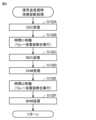
図2は、この実施の形態における車両10のECU100によって実行される充放電制御処理の流れを示すフローチャートである。この充放電制御処理は、ECU100によって上位の処理から所定周期ごとに呼出されて実行される。Figure 2 is a flowchart showing the flow of the charge/discharge control process executed by the
図2を参照して、VPPにおいては、複数のエネルギリソースを束ねるアグリゲータのサーバから、各エネルギリソース(ここでは、車両10の蓄電装置11)の制御装置(ここでは、DC給電設備200の制御装置230に対して電気設備(ここでは、電力系統400)との間の電力の需給の指示が出される。この電力の需給の指示に応じて、DC給電設備200の制御装置230は、車両10のECU100と協調して、蓄電装置11の充放電を制御する。Referring to FIG. 2, in a VPP, an aggregator server that bundles multiple energy resources issues instructions to the control device (here, the
充放電制御処理において、まず、車両10のECU100のCPU110は、アグリゲータからの電力の需給の指示に応じた充放電が中断された後に、DC給電設備200から充放電を再開する指示が有ったか否かを判断する(ステップS111)。In the charge/discharge control process, first, the
充放電の再開の指示が無い(ステップS111でNO)と判断した場合、CPU110は、インレット90にコネクタ310が接続された後に、DC給電設備200から充放電を開始する最初の指示が有ったか否かを判断する(ステップS112)。If it is determined that there is no instruction to resume charging/discharging (NO in step S111), the
充放電を開始する最初の指示が有った(ステップS112でYES)と判断した場合、CPU110は、DC給電設備200と車両10との間で充放電のためのシーケンスとして、絶縁診断前の信号の送受信を行う(ステップS113)。If it is determined that an initial command to start charging/discharging has been received (YES in step S112), the
たとえば、GB/TのV2G規格の場合、絶縁診断前に送受信される信号として、DC給電設備200などの充放電器と車両10との間の物理的な接続が完了したことを検知したことを充放電器から車両10に伝達するためのCDC信号、CDC信号を受信したことを車両10から充放電器に伝達するためのBDC信号、充放電器において制御用電源の投入が完了したことを検知したことを充放電器から車両10に伝達するためのCHM信号、および、CHM信号を受信したことを車両10から充放電器に伝達するためのBHM信号が含まれる。GB/TのV2G規格においては、CDC信号の出力からBDC信号の出力までの期間、および、CHM信号の出力からBHM信号の出力までの期間に、待機期間が設けられている。For example, in the case of the GB/T V2G standard, signals transmitted and received before insulation diagnosis include a CDC signal for transmitting from the charger/discharger to the
絶縁診断前の信号の送受信後に、CPU110は、充放電のための電力線の絶縁診断を実行する(ステップS114)。絶縁診断においては、車両10とDC給電設備200との間の電力線と他の部分との絶縁が保たれているか否かが診断される。具体的には、CPU110は、DC給電設備200の漏電検出器260が漏電を検出してない旨の信号を、DC給電設備200から受信していないか否かによって、絶縁が保たれているか否かを判断する。After transmitting and receiving the signal before the insulation diagnosis, the
CPU110は、絶縁診断において絶縁が保たれていると判断した場合、DC給電設備200の制御装置230と協調して、充電または放電のいずれかの制御を実行する(ステップS115)。If the insulation diagnosis determines that insulation is maintained, the
充放電を開始する最初の指示が無い(ステップS112でNO)と判断した場合、または、ステップS115の後、CPU110は、DC給電設備200から、充電から放電に切替える指示または放電から充電に切替える指示が有ったか否かを判断する(ステップS121)。If it is determined that there is no initial instruction to start charging or discharging (NO in step S112), or after step S115, the
充放電を切替える指示が有った(ステップS121でYES)と判断した場合、CPU110は、充放電を停止し(ステップS122)、充電リレー71,72の溶着診断を実行し、溶着診断の実行結果をメモリ120に記憶させる(ステップS123)。具体的には、CPU110は、溶着診断の実行結果として、接点が溶着しているとの結果を示す情報、接点が溶着していないとの結果を示す情報、または、溶着診断が正常に終了しなかったとの結果を示す情報を、メモリ120に記憶させる。If it is determined that an instruction to switch between charging and discharging has been given (YES in step S121), the
たとえば、溶着診断においては、以下のように溶着を判定する。CPU110が、充電リレー71,72の両方を開放状態とする制御信号を充電リレー71,72に出力し、電圧センサ80の検出している電圧VDCの絶対値が所定電圧(たとえば、0V)以下であるか否かを判断し、所定電圧以下でないと判断した場合、両方の充電リレー71,72の接点が溶着していると判定する。CPU110が、充電リレー71を開放状態とする制御信号を出力する一方、充電リレー72を閉成状態とする制御信号を出力し、電圧センサ80の検出している電圧VDCの絶対値が所定電圧(たとえば、0V)以下であるか否かを判断し、所定電圧以下でないと判断した場合、充電リレー71の接点が溶着していると判定する。CPU110が、充電リレー72を開放状態とする制御信号を出力する一方、充電リレー71を閉成状態とする制御信号を出力し、電圧センサ80の検出している電圧VDCの絶対値が所定電圧(たとえば、0V)以下であるか否かを判断し、所定電圧以下でないと判断した場合、充電リレー72の接点が溶着していると判定する。For example, in a welding diagnosis, welding is determined as follows:
CPU110は、ステップS123の溶着診断において、診断に失敗したか、または、溶着していると判断したか否かを判断する(ステップS124)。溶着していない(ステップS124でNO)と判断した場合、または、溶着診断に失敗したと判断した場合、CPU110は、充放電の切替制御(たとえば、車両10とDC給電設備200との間で充放電を切替えるためのシーケンス制御)を実行する(ステップS125)。The
溶着している(ステップS124でYES)と判断した場合、CPU110は、溶着時処理(たとえば、充電リレー71,72の接点が溶着している旨を表示装置60に表示させる処理および車両10の走行機能などの所定機能を停止させる処理)を実行する(ステップS126)。ステップS126の後、CPU110は、この充放電制御処理を終了させる。If it is determined that the contacts of the charging relays 71 and 72 are welded (YES in step S124), the
充放電の再開の指示が有った(ステップS111でYES)と判断した場合、CPU110は、メモリ120に記憶された診断結果を用いて、直前の溶着診断が失敗であったか否かを判断する(ステップS131)。溶着診断が失敗でなかった(ステップS131でNO)と判断した場合、CPU110は、実行する処理を前述のステップS113の処理に進める。If it is determined that an instruction to resume charging/discharging has been given (YES in step S111), the
溶着診断が失敗であった(ステップS131でYES)と判断した場合、CPU110は、DC給電設備200と車両10との間で充放電のためのシーケンスとして、前述したような絶縁診断前の信号の送受信を行うことに加えて、信号の送受信の待機期間で充電リレー71,72の溶着診断を実行する(ステップS132)。If the
図3は、この実施の形態における車両10のECU100によって実行される信号送受信時溶着診断処理の流れを示すフローチャートである。図3を参照して、この処理は、図2の充放電制御処理のステップS132で実行される処理である。Figure 3 is a flowchart showing the flow of the signal transmission/reception welding diagnosis process executed by the
まず、車両10のECU100のCPU110は、DC給電設備200からCDC信号を受信する(ステップS132A)。CDC信号を受信した後、CPU110は、BDC信号の送信を時間t1の間、待機し、その待機期間に、充電リレー71,72の溶着診断を実行する(ステップS132B)。BDC信号の送信までの待機期間の時間t1は、シーケンス(この場合、GB/TのV2G規格のシーケンス)において予め定められた時間である。CPU110は、時間t1が経過すると、溶着診断が終了していなくても、一旦、溶着診断を中断し、BDC信号をDC給電設備200に出力する(ステップS132C)。First, the
次に、CPU110は、DC給電設備200からCHM信号を受信する(ステップS132D)。CHM信号を受信した後、CPU110は、BHM信号の送信を時間t2の間、待機し、その待機期間に、充電リレー71,72の溶着診断を中断していた場合、溶着診断の続きを実行する(ステップS132E)。BHM信号の送信までの待機期間の時間t2は、シーケンス(この場合、GB/TのV2G規格のシーケンス)において予め定められた時間である。CPU110は、時間t2が経過すると、BHM信号をDC給電設備200に出力する(ステップS132F)。なお、溶着診断に要する時間は、時間t1+t2未満である。ステップS132Fの後、CPU110は、実行する処理を図2の充放電制御処理に戻す。Next, the
図2に戻って、CPU110は、ステップS132の溶着診断において、溶着していると判断したか否かを判断する(ステップS133)。溶着していない(ステップS133でNO)と判断した場合、CPU110は、前述したステップS114以降の処理を実行する。溶着している(ステップS133でYES)と判断した場合、CPU110は、前述したステップS126以降の処理を実行する。Returning to FIG. 2, the
充放電を切替える指示が無い(ステップS121でNO)と判断した場合、または、ステップS125の後、CPU110は、DC給電設備200から、充放電を終了させる指示が有ったか否かを判断する(ステップS141)。充放電を終了させる指示が有った(ステップS141でYES)と判断した場合、CPU110は、充放電を停止し(ステップS142)、前述のステップS123と同様に、充電リレー71,72の溶着診断を実行する(ステップS143)。If it is determined that there is no instruction to switch between charging and discharging (NO in step S121), or after step S125, the
CPU110は、ステップS143の溶着診断において、溶着していると判断したか否かを判断する(ステップS144)。溶着していない(ステップS124でNO)と判断した場合、または、充放電を終了させる指示が無い(ステップS141でNO)と判断した場合、CPU110は、実行する処理をこの充放電制御処理の呼出元の上位の処理に戻す。溶着している(ステップS144でYES)と判断した場合、CPU110は、前述したステップS126以降の処理を実行する。The
[第2実施形態]
前述した第1実施形態においては、車両10の蓄電装置11と電力系統400との間の双方向の電力の遣り取りであるV2Gにおける実施形態を説明した。第2実施形態においては、電力系統400から車両10の蓄電装置11への一方向の電力の供給における実施形態を説明する。 [Second embodiment]
In the above-described first embodiment, an embodiment has been described in V2G, which is a bidirectional exchange of power between the
図4は、第2実施形態における車両10のECU100によって実行される充電制御処理の流れを示すフローチャートである。この充電制御処理は、ECU100によって上位の処理から所定周期ごとに呼出されて実行される。Figure 4 is a flowchart showing the flow of the charging control process executed by the
図4を参照して、VPPにおいては、複数のエネルギリソースを束ねるアグリゲータのサーバから、各エネルギリソース(ここでは、車両10の蓄電装置11)の制御装置(ここでは、DC給電設備200の制御装置230に対して電気設備(ここでは、電力系統400)との間の電力の供給の指示が出される。この電力の供給の指示に応じて、DC給電設備200の制御装置230は、車両10のECU100と協調して、蓄電装置11の充電を制御する。Referring to FIG. 4, in a VPP, an aggregator server that bundles multiple energy resources issues an instruction to a control device (here, the
充電制御処理において、まず、車両10のECU100のCPU110は、アグリゲータからの電力の供給の指示に応じた充電を開始する指示が、DC給電設備200から有ったか否かを判断する(ステップS151)。In the charging control process, first, the
充電を開始する指示が有った(ステップS151でYES)と判断した場合、CPU110は、メモリ120に記憶された診断結果を用いて、前回の溶着診断が失敗であったか否かを判断する(ステップS152)。溶着診断が失敗でなかった(ステップS152でNO)と判断した場合、CPU110は、DC給電設備200と車両10との間で充電のためのシーケンスとして、図2のステップS113と同様、絶縁診断前の信号の送受信を行う(ステップS153)。If it is determined that an instruction to start charging has been given (YES in step S151), the
絶縁診断前の信号の送受信後に、CPU110は、図2のステップS114と同様、充放電のための電力線の絶縁診断を実行する(ステップS154)。After transmitting and receiving the signal before the insulation diagnosis, the
CPU110は、絶縁診断において絶縁が保たれていると判断した場合、DC給電設備200の制御装置230と協調して、充電の制御を実行する(ステップS155)。If the insulation diagnosis determines that insulation is maintained, the
溶着診断が失敗であった(ステップS152でYES)と判断した場合、CPU110は、図2のステップS115と同様、DC給電設備200と車両10との間で充電のためのシーケンスとして、前述したような絶縁診断前の信号の送受信を行うことに加えて、信号の送受信の待機期間で充電リレー71,72の溶着診断を実行する(ステップS162)。If it is determined that the welding diagnosis has failed (YES in step S152), the
CPU110は、ステップS162の溶着診断において、溶着していると判断したか否かを判断する(ステップS163)。溶着していない(ステップS163でNO)と判断した場合、CPU110は、前述したステップS154以降の処理を実行する。溶着している(ステップS163でYES)と判断した場合、図2のステップS126と同様、溶着時処理(たとえば、充電リレー71,72の接点が溶着している旨を表示装置60に表示させる処理および車両10の走行機能などの所定機能を停止させる処理)を実行する(ステップS166)。ステップS166の後、CPU110は、この充電制御処理を終了させる。The
充電を開始する指示が無い(ステップS151でNO)と判断した場合、または、ステップS155の後、CPU110は、DC給電設備200から、充放電を終了させる指示が有ったか否かを判断する(ステップS171)。充放電を終了させる指示が有った(ステップS171でYES)と判断した場合、CPU110は、充放電を停止し(ステップS172)、図2のステップS123と同様、充電リレー71,72の溶着診断を実行し、溶着診断の実行結果をメモリ120に記憶させる(ステップS173)。If it is determined that there is no instruction to start charging (NO in step S151), or after step S155, the
CPU110は、ステップS173の溶着診断において、診断に失敗したか、または、溶着していると判断したか否かを判断する(ステップS174)。溶着していない(ステップS174でNO)と判断した場合、または、充放電を終了させる指示が無い(ステップS171でNO)と判断した場合、CPU110は、実行する処理をこの充電制御処理の呼出元の上位の処理に戻す。溶着している(ステップS174でYES)と判断した場合、CPU110は、前述したステップS166以降の処理を実行する。The
[変形例]
(1) 前述した実施の形態においては、図2から図4で示した各ステップの処理がソフトウェアとして車両10のECU100のCPU110によって実行されるようにした。しかし、これに限定されず、図2から図4で示した各ステップの処理のうちの少なくとも一部の処理が車両10に備えられるハードウェアによって実行されるようにしてもよい。 [Modification]
(1) In the embodiment described above, the processes of the steps shown in Figures 2 to 4 are executed as software by the
(2) 前述した実施の形態においては、図1で示したように、DC給電設備200が充放電器であることとした。しかし、これに限定されず、充放電器は、他の装置であってもよく、たとえば、AC給電設備であってもよいし、急速充放電器であってもよいし、普通充放電器であってもよいし、車載充電ケーブルであってもよい。(2) In the above-described embodiment, as shown in FIG. 1, the DC
(3) 前述した実施の形態においては、図3で示したように、DC給電設備200などの充放電器と車両10との間の充放電のためのシーケンスが、GB/TのV2G規格のシーケンスであることとした。しかし、充放電のためのシーケンスは、これに限定されず、GB/TのV2G以外の規格のシーケンスであってもよいし、他の規格(たとえば、CHAdeMO規格など)のシーケンスであってもよいし、車両10またはDC給電設備200のような充放電器のメーカの独自のシーケンスであってもよい。(3) In the above-described embodiment, as shown in FIG. 3, the sequence for charging and discharging between a charger/discharger such as DC
(4) 前述した実施の形態においては、図2および図4で示した処理がすべて、車両10のECU100によって実行されるようにした。しかし、これに限定されず、図4および図4で示した処理の少なくとも一部が、DC給電設備200の制御装置230で実行されるようにしてもよい。(4) In the above-described embodiment, all of the processes shown in FIG. 2 and FIG. 4 are executed by the
(5) 前述した実施の形態においては、図2のステップS132で示したように、絶縁診断前の信号送受信の待ち時間のような通信中の待機期間に、充電リレー71,72の溶着診断を実行するようにした。しかし、これに限定されず、溶着診断は、絶縁診断の前に実行されるようにすればよく、たとえば、絶縁診断前の信号送受信のような通信の後、かつ、絶縁診断の前の期間に実行されるようにしてもよく、絶縁診断前の信号送受信のいずれかを遅らせることで得られる期間に実行されるようにしてもよい。(5) In the above-described embodiment, as shown in step S132 of FIG. 2, a welding diagnosis of the charging relays 71 and 72 is performed during a waiting period during communication, such as the waiting time for signal transmission and reception before an insulation diagnosis. However, this is not limited to this, and the welding diagnosis may be performed before an insulation diagnosis. For example, the welding diagnosis may be performed during a period after communication, such as signal transmission and reception before an insulation diagnosis, and before an insulation diagnosis, or during a period obtained by delaying either the signal transmission or reception before an insulation diagnosis.
(6) 前述した実施の形態を、車両10、DC給電設備200のような充放電器もしくは充電器、または、充放電システム1の開示と捉えることができるし、車両10のECU100またはDC給電設備200の制御装置230のような制御装置の開示と捉えることができるし、これらの制御装置で実行される制御方法または制御プログラムの開示と捉えることができる。(6) The above-described embodiment can be understood as a disclosure of a charger or charger such as the
[まとめ]
(1) 図2のステップS113で示したように、車両10は、充電または放電を開始するための通信後の絶縁診断の前に待機期間を確保可能なシーケンスにしたがって充電または放電する車両10である。図1で示したように、車両10は、電力を充放電可能な蓄電装置11と、DC給電設備200および蓄電装置11の間の電路を遮断または接続する接点の開閉を切替える充電リレー71,72と、蓄電装置11の充放電および充電リレー71,72を制御するECU100とを備える。図2および図4で示したように、ECU100は、充電リレー71,72の接点を開に制御した後に接点の溶着診断を実行し(たとえば、図2のステップS123、図4のステップS173)、溶着診断が正常に終了したか否かを判断し(たとえば、図2のステップS124、図4のステップS174)、接点を閉に制御するときに、溶着診断が正常に終了していないと判断した場合、待機期間に、溶着診断を実行する(たとえば、図2のステップS131,ステップS132、図4のステップS152,ステップS162)。 [summary]
(1) As shown in step S113 of Fig. 2,
これにより、充電リレー71,72の接点が開に制御された後に接点の溶着診断が正常に終了していない場合、充電または放電を開始するための通信後の絶縁診断の前の待機期間に、溶着診断が実行される。その結果、ユーザの介入無く充電または放電のシーケンスを繰返す場合において適切に溶着の診断を行うことができる。As a result, if the contact welding diagnosis is not completed normally after the contacts of the charging relays 71 and 72 are controlled to be open, the welding diagnosis is performed during the waiting period before the insulation diagnosis after communication to start charging or discharging. As a result, it is possible to appropriately perform the welding diagnosis when the charging or discharging sequence is repeated without user intervention.
(2) 図2および図4で示したように、ECU100は、待機期間での溶着診断の実行後に、絶縁診断を実行する(たとえば、図2のステップS133で溶着していないと判断された場合に、ステップS114で絶縁診断が実行される。図4のステップS163で溶着していないと判断された場合に、ステップS154で絶縁診断が実行される。)。これにより、溶着診断が完了していないのに絶縁診断が実行されてしまうことを防止できる。(2) As shown in FIG. 2 and FIG. 4, the
(3) 図1で示したように、ECU100は、メモリ120を含む。図2および図4で示したように、溶着診断の実行結果をメモリ120に記憶させ(たとえば、図2のステップS123、図4のステップS173)、メモリ120に記憶された実行結果を用いて溶着診断が正常に終了したか否かを判断する(たとえば、図2のステップS131、図4のステップS152)。これにより、溶着診断が正常に終了したか否かを適切に判断することが可能となる。(3) As shown in FIG. 1, the
(4) 図2および図4で示したように、ECU100は、溶着診断の実行結果として、接点が溶着しているとの結果を示す情報、接点が溶着していないとの結果を示す情報、または、溶着診断が正常に終了しなかったとの結果を示す情報をメモリ120に記憶させる(たとえば、図2のステップS123、図4のステップS173)。これにより、溶着診断の実行結果を用いて、適切に、溶着診断が正常に終了したか否かの判断することが可能となる。(4) As shown in FIG. 2 and FIG. 4,
今回開示された実施の形態は、すべての点で例示であって制限的なものではないと考えられるべきである。本開示の範囲は、上記した実施の形態の説明ではなくて特許請求の範囲によって示され、特許請求の範囲と均等の意味および範囲内でのすべての変更が含まれることが意図される。The embodiments disclosed herein should be considered to be illustrative and not restrictive in all respects. The scope of the present disclosure is indicated by the claims rather than the description of the embodiments above, and is intended to include all modifications within the meaning and scope of the claims.
1 充放電システム、10 車両、11 蓄電装置、15 監視ユニット、16,80 電圧センサ、17 電流センサ、18 温度センサ、21,22 SMR、30 PCU、40 MG、50 動力伝達ギヤ、55 駆動輪、60 表示装置、71,72 充電リレー、90 インレット、100 ECU、110 CPU、120 メモリ、130,220 通信装置、200 DC給電設備、230 制御装置、240 充電開始スイッチ、250 充電停止スイッチ、260 漏電検出器、300 充電ケーブル、310 コネクタ、400 電力系統。1 Charging and discharging system, 10 Vehicle, 11 Power storage device, 15 Monitoring unit, 16, 80 Voltage sensor, 17 Current sensor, 18 Temperature sensor, 21, 22 SMR, 30 PCU, 40 MG, 50 Power transmission gear, 55 Drive wheel, 60 Display device, 71, 72 Charging relay, 90 Inlet, 100 ECU, 110 CPU, 120 Memory, 130, 220 Communication device, 200 DC power supply equipment, 230 Control device, 240 Charging start switch, 250 Charging stop switch, 260 Leakage detector, 300 Charging cable, 310 Connector, 400 Power system.
Claims (5)
Translated fromJapanese前記車両は、
電力を充放電可能な蓄電装置と、
外部装置および前記蓄電装置の間の電路を遮断または接続する接点の開閉を切替えるリレーと、
前記蓄電装置の充放電および前記リレーを制御する制御装置とを備え、
前記制御装置は、
前記リレーの前記接点を開に制御した後に前記接点の溶着診断を実行し、
前記溶着診断が正常に終了したか否かを判断し、
前記接点を閉に制御するときに、前記溶着診断が正常に終了していないと判断した場合、前記待機期間に、前記溶着診断を実行する、車両。 A vehicle that charges or discharges according to a sequence that can ensure a waiting period before an insulation diagnosis after communication for starting charging or discharging,
The vehicle is
A power storage device capable of charging and discharging electric power;
a relay that switches between opening and closing a contact that connects or breaks an electric path between an external device and the power storage device;
a control device for controlling charging and discharging of the power storage device and the relay;
The control device includes:
and performing a welding diagnosis on the contact after controlling the contact of the relay to be open;
determining whether the welding diagnosis has been completed normally;
When it is determined that the welding diagnosis has not ended normally when controlling the contacts to be closed, the welding diagnosis is executed during the waiting period.
前記待機期間での前記溶着診断の実行後に、前記絶縁診断を実行する、請求項1に記載の車両。 The control device includes:
The vehicle according to claim 1 , wherein the insulation diagnosis is performed after the welding diagnosis is performed during the waiting period.
前記制御装置は、
前記溶着診断の実行結果を前記メモリに記憶させ、
前記メモリに記憶された前記実行結果を用いて前記溶着診断が正常に終了したか否かを判断する、請求項1または請求項2に記載の車両。 The control device includes a memory.
The control device includes:
storing the execution result of the welding diagnosis in the memory;
3. The vehicle according to claim 1, wherein the execution result stored in the memory is used to determine whether the welding diagnosis has been completed normally.
前記車両は、
電力を充放電可能な蓄電装置と、
外部装置および前記蓄電装置の間の電路を遮断または接続する接点の開閉を切替えるリレーとを備え、
前記制御装置は、
前記蓄電装置の充放電および前記リレーを制御し、
前記リレーの前記接点を開に制御した後に前記接点の溶着診断を実行し、
前記溶着診断が正常に終了したか否かを判断し、
前記接点を閉に制御するときに、前記溶着診断が正常に終了していないと判断した場合、前記待機期間に、前記溶着診断を実行する、車両の制御装置。
A control device for a vehicle that charges or discharges according to a sequence that can ensure a waiting period before an insulation diagnosis after communication for starting charging or discharging,
The vehicle is
A power storage device capable of charging and discharging electric power;
a relay that switches between opening and closing a contact that connects or breaks an electric path between an external device and the power storage device,
The control device includes:
Controlling charging and discharging of the power storage device and the relay;
and performing a welding diagnosis on the contact after controlling the contact of the relay to be open;
determining whether the welding diagnosis has been completed normally;
A control device for a vehicle that, when controlling the contacts to be closed, determines that the welding diagnosis has not ended normally, executes the welding diagnosis during the standby period.
Priority Applications (1)
| Application Number | Priority Date | Filing Date | Title |
|---|---|---|---|
| JP2021205952AJP7626053B2 (en) | 2021-12-20 | 2021-12-20 | Vehicle and vehicle control device |
Applications Claiming Priority (1)
| Application Number | Priority Date | Filing Date | Title |
|---|---|---|---|
| JP2021205952AJP7626053B2 (en) | 2021-12-20 | 2021-12-20 | Vehicle and vehicle control device |
Publications (2)
| Publication Number | Publication Date |
|---|---|
| JP2023091287A JP2023091287A (en) | 2023-06-30 |
| JP7626053B2true JP7626053B2 (en) | 2025-02-04 |
Family
ID=86941790
Family Applications (1)
| Application Number | Title | Priority Date | Filing Date |
|---|---|---|---|
| JP2021205952AActiveJP7626053B2 (en) | 2021-12-20 | 2021-12-20 | Vehicle and vehicle control device |
Country Status (1)
| Country | Link |
|---|---|
| JP (1) | JP7626053B2 (en) |
Families Citing this family (1)
| Publication number | Priority date | Publication date | Assignee | Title |
|---|---|---|---|---|
| CN119911121B (en)* | 2025-04-03 | 2025-06-03 | 合肥工业大学 | Whole-vehicle power-on and power-off control method for amphibious transport vehicle with time sequence management |
Citations (7)
| Publication number | Priority date | Publication date | Assignee | Title |
|---|---|---|---|---|
| WO2012004848A1 (en) | 2010-07-05 | 2012-01-12 | トヨタ自動車株式会社 | Charging control device |
| JP2015209103A (en) | 2014-04-25 | 2015-11-24 | トヨタ自動車株式会社 | Vehicle and vehicle control method |
| JP2016119762A (en) | 2014-12-19 | 2016-06-30 | トヨタ自動車株式会社 | Vehicle and charging system |
| US20180294660A1 (en) | 2017-04-06 | 2018-10-11 | Hyundai Motor Company | Apparatus and method for controlling rapid charging of a vehicle |
| JP2019122062A (en) | 2017-12-28 | 2019-07-22 | トヨタ自動車株式会社 | Electric vehicle |
| JP2020127341A (en) | 2019-02-06 | 2020-08-20 | トヨタ自動車株式会社 | vehicle |
| CN113500939A (en) | 2021-07-05 | 2021-10-15 | 华人运通(江苏)技术有限公司 | Method, device and equipment for monitoring state of charging contactor of vehicle |
Family Cites Families (1)
| Publication number | Priority date | Publication date | Assignee | Title |
|---|---|---|---|---|
| JP6287738B2 (en)* | 2014-09-30 | 2018-03-07 | トヨタ自動車株式会社 | vehicle |
- 2021
- 2021-12-20JPJP2021205952Apatent/JP7626053B2/enactiveActive
Patent Citations (7)
| Publication number | Priority date | Publication date | Assignee | Title |
|---|---|---|---|---|
| WO2012004848A1 (en) | 2010-07-05 | 2012-01-12 | トヨタ自動車株式会社 | Charging control device |
| JP2015209103A (en) | 2014-04-25 | 2015-11-24 | トヨタ自動車株式会社 | Vehicle and vehicle control method |
| JP2016119762A (en) | 2014-12-19 | 2016-06-30 | トヨタ自動車株式会社 | Vehicle and charging system |
| US20180294660A1 (en) | 2017-04-06 | 2018-10-11 | Hyundai Motor Company | Apparatus and method for controlling rapid charging of a vehicle |
| JP2019122062A (en) | 2017-12-28 | 2019-07-22 | トヨタ自動車株式会社 | Electric vehicle |
| JP2020127341A (en) | 2019-02-06 | 2020-08-20 | トヨタ自動車株式会社 | vehicle |
| CN113500939A (en) | 2021-07-05 | 2021-10-15 | 华人运通(江苏)技术有限公司 | Method, device and equipment for monitoring state of charging contactor of vehicle |
Also Published As
| Publication number | Publication date |
|---|---|
| JP2023091287A (en) | 2023-06-30 |
Similar Documents
| Publication | Publication Date | Title |
|---|---|---|
| US9090169B2 (en) | Adapter and vehicle for performing power feeding using adapter | |
| US9434257B2 (en) | Power supply connector, vehicle and control method for vehicle | |
| US8988042B2 (en) | Vehicle, charging system and control method for vehicle | |
| JP5327328B2 (en) | Charge control device and vehicle | |
| JP4883247B2 (en) | Charging system, vehicle and charging system control method | |
| JP6044460B2 (en) | Vehicle power supply | |
| US8487636B2 (en) | Malfunction determining apparatus and malfunction determining method for charging system | |
| US9257867B2 (en) | Vehicle | |
| US9614379B2 (en) | Adapter, and vehicle and method for performing power feeding using adapter | |
| EP2596981B1 (en) | Control device for vehicle and control method for vehicle | |
| JP5854242B2 (en) | Electric power supply device using electric vehicle | |
| US20100198440A1 (en) | Vehicle and method of charging vehicle | |
| US11427084B2 (en) | Vehicle | |
| JP7079223B2 (en) | Battery status determination system, in-vehicle device, server, battery status determination method, and program | |
| JP2012162176A (en) | Vehicle and vehicle control method | |
| JP7652101B2 (en) | CHARGING/DISCHARGING DEVICE, VEHICLE, AND METHOD FOR CONTROLLING CHARGING/DISCHARGING DEVICE | |
| JP2021128023A (en) | Battery diagnostic device and vehicle | |
| JP7626053B2 (en) | Vehicle and vehicle control device | |
| JP2022152266A (en) | vehicle | |
| JP2011239556A (en) | Vehicle | |
| JP2012130155A (en) | Charger and electric vehicle including the same | |
| JP7605159B2 (en) | vehicle |
Legal Events
| Date | Code | Title | Description |
|---|---|---|---|
| A621 | Written request for application examination | Free format text:JAPANESE INTERMEDIATE CODE: A621 Effective date:20240320 | |
| TRDD | Decision of grant or rejection written | ||
| A977 | Report on retrieval | Free format text:JAPANESE INTERMEDIATE CODE: A971007 Effective date:20241218 | |
| A01 | Written decision to grant a patent or to grant a registration (utility model) | Free format text:JAPANESE INTERMEDIATE CODE: A01 Effective date:20241224 | |
| A61 | First payment of annual fees (during grant procedure) | Free format text:JAPANESE INTERMEDIATE CODE: A61 Effective date:20250106 | |
| R150 | Certificate of patent or registration of utility model | Ref document number:7626053 Country of ref document:JP Free format text:JAPANESE INTERMEDIATE CODE: R150 |