JP7625935B2 - Cartridge and printing system - Google Patents
Cartridge and printing systemDownload PDFInfo
- Publication number
- JP7625935B2 JP7625935B2JP2021056848AJP2021056848AJP7625935B2JP 7625935 B2JP7625935 B2JP 7625935B2JP 2021056848 AJP2021056848 AJP 2021056848AJP 2021056848 AJP2021056848 AJP 2021056848AJP 7625935 B2JP7625935 B2JP 7625935B2
- Authority
- JP
- Japan
- Prior art keywords
- liquid
- cartridge
- absorbing member
- section
- liquid absorbing
- Prior art date
- Legal status (The legal status is an assumption and is not a legal conclusion. Google has not performed a legal analysis and makes no representation as to the accuracy of the status listed.)
- Active
Links
- 238000007639printingMethods0.000titleclaimsdescription69
- 239000007788liquidSubstances0.000claimsdescription319
- 239000000976inkSubstances0.000description39
- 238000000034methodMethods0.000description19
- 238000003780insertionMethods0.000description17
- 230000037431insertionEffects0.000description17
- 230000007246mechanismEffects0.000description11
- 239000000463materialSubstances0.000description9
- 238000005516engineering processMethods0.000description6
- 230000005484gravityEffects0.000description6
- 238000004891communicationMethods0.000description5
- 238000010586diagramMethods0.000description5
- 239000006096absorbing agentSubstances0.000description4
- 229920005989resinPolymers0.000description4
- 239000011347resinSubstances0.000description4
- 230000015572biosynthetic processEffects0.000description3
- 238000004519manufacturing processMethods0.000description3
- 239000007921spraySubstances0.000description3
- 238000005507sprayingMethods0.000description3
- 238000010521absorption reactionMethods0.000description2
- 230000000694effectsEffects0.000description2
- 238000005401electroluminescenceMethods0.000description2
- 238000009434installationMethods0.000description2
- 238000011900installation processMethods0.000description2
- 239000004973liquid crystal related substanceSubstances0.000description2
- 239000010687lubricating oilSubstances0.000description2
- 230000008531maintenance mechanismEffects0.000description2
- 230000003287optical effectEffects0.000description2
- 239000000758substrateSubstances0.000description2
- 230000007723transport mechanismEffects0.000description2
- XLYOFNOQVPJJNP-UHFFFAOYSA-NwaterSubstancesOXLYOFNOQVPJJNP-UHFFFAOYSA-N0.000description2
- 238000000018DNA microarrayMethods0.000description1
- JOYRKODLDBILNP-UHFFFAOYSA-NEthyl urethaneChemical compoundCCOC(N)=OJOYRKODLDBILNP-UHFFFAOYSA-N0.000description1
- 208000016169Fish-eye diseaseDiseases0.000description1
- 239000004743PolypropyleneSubstances0.000description1
- 239000004372Polyvinyl alcoholSubstances0.000description1
- 230000004308accommodationEffects0.000description1
- 230000002378acidificating effectEffects0.000description1
- 238000013459approachMethods0.000description1
- 239000003086colorantSubstances0.000description1
- 230000005489elastic deformationEffects0.000description1
- 239000007772electrode materialSubstances0.000description1
- 230000003028elevating effectEffects0.000description1
- 238000005530etchingMethods0.000description1
- 239000006260foamSubstances0.000description1
- 239000012943hotmeltSubstances0.000description1
- 238000001746injection mouldingMethods0.000description1
- 229910001867inorganic solventInorganic materials0.000description1
- 239000003049inorganic solventSubstances0.000description1
- 239000007791liquid phaseSubstances0.000description1
- 229910001338liquidmetalInorganic materials0.000description1
- 238000012423maintenanceMethods0.000description1
- 239000008204material by functionSubstances0.000description1
- 239000002184metalSubstances0.000description1
- 229910052751metalInorganic materials0.000description1
- 239000002923metal particleSubstances0.000description1
- 239000000203mixtureSubstances0.000description1
- 239000004745nonwoven fabricSubstances0.000description1
- 239000003921oilSubstances0.000description1
- 239000005416organic matterSubstances0.000description1
- 239000003960organic solventSubstances0.000description1
- 239000002245particleSubstances0.000description1
- 239000000049pigmentSubstances0.000description1
- -1polypropylenePolymers0.000description1
- 229920001155polypropylenePolymers0.000description1
- 229920002451polyvinyl alcoholPolymers0.000description1
- 239000007787solidSubstances0.000description1
- 239000000243solutionSubstances0.000description1
- 239000002904solventSubstances0.000description1
- 229920003002synthetic resinPolymers0.000description1
- 239000000057synthetic resinSubstances0.000description1
Images


Classifications
- B—PERFORMING OPERATIONS; TRANSPORTING
- B41—PRINTING; LINING MACHINES; TYPEWRITERS; STAMPS
- B41J—TYPEWRITERS; SELECTIVE PRINTING MECHANISMS, i.e. MECHANISMS PRINTING OTHERWISE THAN FROM A FORME; CORRECTION OF TYPOGRAPHICAL ERRORS
- B41J2/00—Typewriters or selective printing mechanisms characterised by the printing or marking process for which they are designed
- B41J2/005—Typewriters or selective printing mechanisms characterised by the printing or marking process for which they are designed characterised by bringing liquid or particles selectively into contact with a printing material
- B41J2/01—Ink jet
- B41J2/17—Ink jet characterised by ink handling
- B41J2/175—Ink supply systems ; Circuit parts therefor
- B41J2/17503—Ink cartridges
- B41J2/17513—Inner structure
- B—PERFORMING OPERATIONS; TRANSPORTING
- B41—PRINTING; LINING MACHINES; TYPEWRITERS; STAMPS
- B41J—TYPEWRITERS; SELECTIVE PRINTING MECHANISMS, i.e. MECHANISMS PRINTING OTHERWISE THAN FROM A FORME; CORRECTION OF TYPOGRAPHICAL ERRORS
- B41J2/00—Typewriters or selective printing mechanisms characterised by the printing or marking process for which they are designed
- B41J2/005—Typewriters or selective printing mechanisms characterised by the printing or marking process for which they are designed characterised by bringing liquid or particles selectively into contact with a printing material
- B41J2/01—Ink jet
- B41J2/17—Ink jet characterised by ink handling
- B41J2/175—Ink supply systems ; Circuit parts therefor
- B41J2/17503—Ink cartridges
- B41J2/1752—Mounting within the printer
- B41J2/17523—Ink connection
- B—PERFORMING OPERATIONS; TRANSPORTING
- B41—PRINTING; LINING MACHINES; TYPEWRITERS; STAMPS
- B41J—TYPEWRITERS; SELECTIVE PRINTING MECHANISMS, i.e. MECHANISMS PRINTING OTHERWISE THAN FROM A FORME; CORRECTION OF TYPOGRAPHICAL ERRORS
- B41J2/00—Typewriters or selective printing mechanisms characterised by the printing or marking process for which they are designed
- B41J2/005—Typewriters or selective printing mechanisms characterised by the printing or marking process for which they are designed characterised by bringing liquid or particles selectively into contact with a printing material
- B41J2/01—Ink jet
- B41J2/17—Ink jet characterised by ink handling
- B41J2/175—Ink supply systems ; Circuit parts therefor
- B41J2/17503—Ink cartridges
- B41J2/17506—Refilling of the cartridge
- B41J2/17509—Whilst mounted in the printer
- B—PERFORMING OPERATIONS; TRANSPORTING
- B41—PRINTING; LINING MACHINES; TYPEWRITERS; STAMPS
- B41J—TYPEWRITERS; SELECTIVE PRINTING MECHANISMS, i.e. MECHANISMS PRINTING OTHERWISE THAN FROM A FORME; CORRECTION OF TYPOGRAPHICAL ERRORS
- B41J2/00—Typewriters or selective printing mechanisms characterised by the printing or marking process for which they are designed
- B41J2/005—Typewriters or selective printing mechanisms characterised by the printing or marking process for which they are designed characterised by bringing liquid or particles selectively into contact with a printing material
- B41J2/01—Ink jet
- B41J2/17—Ink jet characterised by ink handling
- B41J2/175—Ink supply systems ; Circuit parts therefor
- B41J2/17503—Ink cartridges
- B41J2/1752—Mounting within the printer
- B—PERFORMING OPERATIONS; TRANSPORTING
- B41—PRINTING; LINING MACHINES; TYPEWRITERS; STAMPS
- B41J—TYPEWRITERS; SELECTIVE PRINTING MECHANISMS, i.e. MECHANISMS PRINTING OTHERWISE THAN FROM A FORME; CORRECTION OF TYPOGRAPHICAL ERRORS
- B41J2/00—Typewriters or selective printing mechanisms characterised by the printing or marking process for which they are designed
- B41J2/005—Typewriters or selective printing mechanisms characterised by the printing or marking process for which they are designed characterised by bringing liquid or particles selectively into contact with a printing material
- B41J2/01—Ink jet
- B41J2/17—Ink jet characterised by ink handling
- B41J2/175—Ink supply systems ; Circuit parts therefor
- B41J2/17503—Ink cartridges
- B41J2/17526—Electrical contacts to the cartridge
- B41J2/1753—Details of contacts on the cartridge, e.g. protection of contacts
- B—PERFORMING OPERATIONS; TRANSPORTING
- B41—PRINTING; LINING MACHINES; TYPEWRITERS; STAMPS
- B41J—TYPEWRITERS; SELECTIVE PRINTING MECHANISMS, i.e. MECHANISMS PRINTING OTHERWISE THAN FROM A FORME; CORRECTION OF TYPOGRAPHICAL ERRORS
- B41J29/00—Details of, or accessories for, typewriters or selective printing mechanisms not otherwise provided for
- B41J29/12—Guards, shields or dust excluders
- B41J29/13—Cases or covers
Landscapes
- Ink Jet (AREA)
Description
Translated fromJapanese本開示は、カートリッジおよび印刷システムについての技術に関する。This disclosure relates to technology relating to cartridges and printing systems.
従来、インクカートリッジについて、インク供給口の外周側部分と、カートリッジ本体の下面のうちの後端部とにわたって形成された凹部に、インクを吸収して保持する吸収体が配置された技術が知られている(特許文献1)。A conventional ink cartridge technology is known in which an absorber that absorbs and holds ink is disposed in a recess formed between the outer periphery of the ink supply port and the rear end of the bottom surface of the cartridge body (Patent Document 1).
従来の技術では、インクカートリッジの吸収体は、インク供給口から重力方向へ漏れ出したインクを吸収する。しかしながら、従来の技術では、インクカートリッジをプリンターから取り外す際に、液体導入部から飛散するインクについては、吸収体によって捕捉できない場合が生じ得る。また、従来の技術では、吸収体が小さく十分なインクを保持できない場合が生じ得る。上記の課題は、インクカートリッジおよびインクカートリッジが着脱可能に装着されるプリンターに限らず、インク以外の液体を収容するカートリッジおよびカートリッジが着脱可能に装着される印刷装置に共通する。In conventional technology, the absorber of the ink cartridge absorbs ink that leaks out of the ink supply port in the direction of gravity. However, in conventional technology, when removing the ink cartridge from the printer, there are cases where the absorber is unable to capture the ink that splashes out from the liquid introduction section. In addition, in conventional technology, there are cases where the absorber is too small to hold enough ink. The above issues are not limited to ink cartridges and printers in which ink cartridges are removably installed, but are common to cartridges that contain liquids other than ink and printing devices in which cartridges are removably installed.
(1)本開示の第1の形態によれば、液体導入部を備える印刷装置に着脱可能に装着されるカートリッジが提供される。このカートリッジは、液体を収容する液体収容部と、前記液体導入部に接続されて、前記液体を前記印刷装置に供給する液体供給部と、前記液体供給部を内側に配置し、前記液体供給部の先端部と対向する底壁を有する配置部であって、前記底壁は前記先端部と対向する位置に前記液体導入部が挿通される開口部を有する、配置部と、前記配置部の内側に配置された第1液体吸収部材であって、前記第1液体吸収部材の一部が前記開口部から露出する第1液体吸収部材と、前記配置部の内側に配置された第2液体吸収部材であって、前記第1液体吸収部材と接触する第2液体吸収部材と、を備える。(1) According to a first aspect of the present disclosure, a cartridge is provided that is detachably mounted on a printing device that includes a liquid introduction section. This cartridge includes a liquid storage section that stores liquid, a liquid supply section that is connected to the liquid introduction section and supplies the liquid to the printing device, an arrangement section that arranges the liquid supply section inside and has a bottom wall that faces a tip end of the liquid supply section, the bottom wall having an opening through which the liquid introduction section is inserted at a position facing the tip end, a first liquid absorbing member arranged inside the arrangement section, a part of the first liquid absorbing member being exposed from the opening, and a second liquid absorbing member arranged inside the arrangement section, the second liquid absorbing member being in contact with the first liquid absorbing member.
(2)本開示の第2の形態によれば、印刷システムが提供される。この印刷システムは上記形態のカートリッジと、前記液体供給部に接続される液体導入部を有する印刷装置と、を備える。(2) According to a second aspect of the present disclosure, a printing system is provided. This printing system includes a cartridge of the above aspect and a printing device having a liquid introduction section connected to the liquid supply section.
A.実施形態:
A-1.印刷システムの構成:
図1は、本開示の実施形態としての印刷システム1の構成を示す斜視図である。図1には、互いに直交する3つの空間軸であるXYZ軸が描かれている。X軸,Y軸,Z軸の矢印が向いている方向は、それぞれX軸,Y軸,Z軸に沿った正の方向を示している。X軸,Y軸,Z軸に沿った正の方向を、それぞれ+X方向,+Y方向,+Z方向とする。X軸,Y軸,Z軸の矢印が向いている方向と逆の方向が、それぞれX軸,Y軸,Z軸に沿った負の方向である。X軸,Y軸,Z軸に沿った負の方向を、それぞれ-X方向,-Y方向,-Z方向とする。X軸,Y軸,Z軸に沿った方向で正負を問わないものを、それぞれX方向,Y方向,Z方向とよぶ。これ以降に示す図及び説明についても同様である。A. Embodiments:
A-1. Printing system configuration:
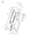
FIG. 1 is a perspective view showing a configuration of a
印刷システム1は、印刷装置10と、印刷装置10に液体であるインクを供給するカートリッジ4とを備える。The
本実施形態の印刷装置10は、液体としてのインクを吐出ヘッド22から吐出するインクジェットプリンターである。この印刷装置10は、ポスター等の大判の用紙(A2~A0等)に印刷を行う大型のプリンターである。印刷装置10は、カートリッジ装着部6と、制御部31と、キャリッジ20と、吐出ヘッド22と、駆動機構30とを備える。また、印刷装置10は、印刷装置10の動作をユーザーが操作するための操作ボタン15を備える。The
カートリッジ装着部6は、+Y方向側に位置する第1装置壁67を有する。第1装置壁67は、カートリッジ4の収容室61への出入口である挿抜開口部674を有する。この挿抜開口部674を介してカートリッジ4がカートリッジ装着部6の収容室61に収容されたり、収容室61からカートリッジ4が取り外されたりする。カートリッジ装着部6には、複数のカートリッジ4がそれぞれ着脱可能に装着される。本実施形態では、ブラック、イエロー、マゼンタ、シアンの4色のインクに対応して4種類のカートリッジ4が1つずつ、すなわち合計4つのカートリッジ4がカートリッジ装着部6に装着される。ブラックのインクを収容するカートリッジ4をカートリッジ4Kとも呼び、イエローのインクを収容するカートリッジ4をカートリッジ4Yとも呼び、マゼンタのインクを収容するカートリッジ4をカートリッジ4Mとも呼び、シアンのインクを収容するカートリッジ4をカートリッジ4Cとも呼ぶ。本実施形態において、カートリッジ4Kは、カートリッジ4C,4M,4Yよりも多くの液体を収容可能に構成されている。よって、カートリッジ4Kを第1種カートリッジ4Aとも呼び、カートリッジ4C,4M,4Yを第2種カートリッジ4Bとも呼ぶ。The
印刷装置10は、+Y方向側の前面に交換用カバー13を有する。交換用カバー13の+Z方向側を+Y方向側である手前側に倒すと、カートリッジ装着部6の開口が現れて、カートリッジ4の着脱が可能となる。カートリッジ装着部6にカートリッジ4が装着されると、液体流通管としてのチューブ24を介してキャリッジ20に設けられた吐出ヘッド22にインクが供給可能となる。本実施形態では、水頭差を利用してカートリッジ4から吐出ヘッド22にインクが供給される。具体的には、カートリッジ装着部6内のインクの液面と吐出ヘッド22との水頭差によってインクが吐出ヘッド22に供給される。なお、他の実施形態では、印刷装置10の図示しないポンプ機構によって、カートリッジ4内のインクを吸引することで、インクが吐出ヘッド22に供給されてもよい。なお、チューブ24は、インクの種類毎に設けられている。ここで、カートリッジ4がカートリッジ装着部6に装着されて、液体としてのインクが印刷装置10に供給できる状態を「装着状態」とも呼ぶ。The
吐出ヘッド22には、インクの種類毎にノズルが設けられている。吐出ヘッド22は、ノズルから印刷用紙2に向かってインクを吐出して文字や画像等のデータを印刷する。なお、本帆実施形態では、印刷装置10は、カートリッジ装着部6がキャリッジ20の動きとは連動しない、いわゆる「オフキャリッジタイプ」と呼ばれるプリンターである。キャリッジ20にカートリッジ装着部6が設けられ、キャリッジ20と共にカートリッジ装着部6が移動する、いわゆる「オンキャリッジタイプ」と呼ばれるプリンターにも本開示の技術は適用できる。The
制御部31は、印刷装置10の各部の制御や、カートリッジ4との信号の授受を行う。キャリッジ20は、吐出ヘッド22を印刷用紙2に対して相対的に移動させる。The
駆動機構30は、制御部31からの制御信号に基づいてキャリッジ20を往復動させる。駆動機構30は、タイミングベルト32と、駆動モーター34とを備える。タイミングベルト32を介して駆動モーター34の動力をキャリッジ20に伝達することによって、キャリッジ20がX方向に沿った方向である主走査方向に往復移動する。また、印刷装置10は、印刷用紙2を+Y方向である副走査方向に移動させるための搬送機構を備える。印刷が行なわれる際には、搬送機構によって印刷用紙2が副走査方向に移動し、前面カバー11上に印刷完了後の印刷用紙2が出力される。The
また、キャリッジ20を主走査方向に移動させた印刷領域外の位置には、ホームポジションと呼ばれる領域が設けられており、ホームポジションには、正常に印刷を実行させるためのメンテナンスを行うメンテナンス機構が搭載されている。メンテナンス機構は、吐出ヘッド22の底面側でノズルが形成されている面に押し付けられて、ノズルを取り囲むように閉空間を形成するキャップ部材8や、吐出ヘッド22のノズル面に押し付けるためにキャップ部材8を昇降させる図示しない昇降機構や、キャップ部材8が吐出ヘッド22のノズル面に押し付けられることで形成される閉空間に負圧を導入する図示しない吸引ポンプなどから構成されている。In addition, an area called the home position is provided outside the printing area when the
本実施形態では、印刷システム1の使用状態において、印刷用紙2を搬送する副走査方向に沿った軸をY軸とし、重力方向に沿った軸をZ軸とし、キャリッジ20の移動方向に沿った軸をX軸とする。ここで、「印刷システム1の使用状態」とは、水平な面に印刷システム1が設置された状態をいう。また、本実施形態では、副走査方向を+Y方向、その逆方向を-Y方向とし、重力方向を-Z方向、反重力方向を+Z方向とする。X方向とY方向は水平方向に沿った方向である。また、印刷システム1を前面側から見たときに、右側から左側に向かう方向を+X方向とし、その逆方向を-X方向とする。また本実施形態では、装着のためにカートリッジ装着部6にカートリッジ4が挿入される挿入方向が-Y方向であり、カートリッジ4がカートリッジ装着部6から取り外される方向が+Y方向である。よって、カートリッジ装着部6のうち、-Y方向側を奥側とも呼び、+Y方向側を手前側とも呼ぶ。また、本実施形態では、複数のカートリッジ4の配列方向がX方向となる。In this embodiment, in the state in which the
A-2.カートリッジの装着過程および装着状態の説明:
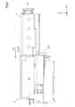
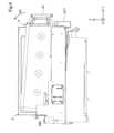
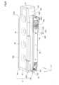
図2は、カートリッジ4のカートリッジ装着部6への装着過程を説明する第1図である。図3は、装着過程を説明する第2図である。図4は、カートリッジ4のカートリッジ装着部6への装着が完了した装着状態を示す図である。A-2. Explanation of the cartridge installation process and installation state:
Fig. 2 is a first diagram for explaining the mounting process of the
装着過程は、端子接続過程と、端子接続過程の次に実行される供給部接続過程とによって構成される。端子接続過程は、図2に示すように、第1装置壁67の挿抜開口部674を介して、カートリッジ4を-Y方向である挿入方向D1に移動させてカートリッジ装着部6の収容室61に挿入することで、カートリッジ装着部6の後述する装置側端子と、カートリッジ4の後述するカートリッジ側端子とを接触させて電気的に接続する過程である。図3および図4に示すように、供給部接続過程は、装置側端子とカートリッジ側端子との電気的な接続を維持した状態で、カートリッジ装着部6の後述する液体導入部とカートリッジ4の後述する液体供給部とを接続する過程である。具体的には、供給部接続過程では、カートリッジ装着部6の回転支点698を中心に、カートリッジ4の後面47側を矢印に示す接続方向D2に回転移動させることで、液体導入部と液体供給部とが接続する。なお、図4に示す装着状態では、カートリッジ4は、カートリッジ装着部6の第1装置壁67側に設けられた係合形成体677によって係合されることで装着状態が保持されている。The mounting process is composed of a terminal connection process and a supply unit connection process that is executed after the terminal connection process. As shown in FIG. 2, the terminal connection process is a process in which the
図4に示すように、カートリッジ4をカートリッジ装着部6から取り出す場合には、ユーザーは、カートリッジ4の後壁47側を持ち上げることで、回転支点698を支点として接続方向D2とは反対方向である接続解除方向D3に後端47側を回転移動させる。この回転移動の際に、係合形成体677による係合が解除される。接続解除方向D3にカートリッジ4を回転移動させてカートリッジ4が図3に示す状態になった後に、取り外し方向である+Y方向にカートリッジ4を移動させることで、カートリッジ装着部6からカートリッジ4が取り出される。As shown in FIG. 4, when removing the
A-3.カートリッジの装着状態の詳細説明:
図5は、カートリッジ装着部6を+Z方向側から見た図である。図6は、図5の6-6断面図である。図7は、図6の領域R7の拡大図である。図5では、カートリッジ装着部6にはカートリッジ4Kが装着されている。図5~図7を用いてカートリッジ4の装着状態について説明する。なお、カートリッジ4C,4M,4Y,4Kについて、装着状態は同じである。A-3. Detailed explanation of cartridge installation state:
Figure 5 is a view of the
図6に示すように、カートリッジ装着部6は、収容室61の収容室底壁を形成する支持部材610を有する。支持部材610は、カートリッジ4を下側から支持する。カートリッジ4がカートリッジ装着部6の収容室61に挿入された状態では、支持部材610によって-Z方向側からカートリッジ4が支持される。また、カートリッジ4がカートリッジ装着部6の収容室61に装着された装着状態では、カートリッジ4の液体供給部442と、カートリッジ装着部6の液体導入部642とが接続される。これにより、カートリッジ4の液体収容部450に収容された液体が、液体供給部442を介して液体導入部642に供給される。また、本実施形態では、液体供給部442から液体導入部642に液体が供給される一方で、カートリッジ装着部6の液体貯留部699に収容された空気が気泡となって、液体導入部642、液体供給部442を流通して液体収容部450に流通する。これにより、液体収容部450の気液交換が行われる。なお、他の実施形態では、カートリッジ4が液体収容部450と外部とを連通させる大気連通路を有し、この大気連通路を介して気液交換が行われてもよい。大気連通路は液体供給部442とは異なる位置に配置されており、例えば、液体収容部450を形成する壁に形成される。As shown in FIG. 6, the
液体導入部642は、カートリッジ4から供給される液体を受け入れる。液体導入部642は、筒状の部材であり、内部に液体を流通させる内部流路を有する。液体導入部642は、基端642aと先端642bとを有する。先端642bには、内部流路である導入部流路に連通する開口が形成されており、この開口を介して液体供給部442のインクが導入部流路に流通する。基端642aは、液体貯留部699に接続されており、導入部流路を流通したインクを液体貯留部699に流通させる。液体貯留部699は、収容室61の-Z方向側に位置する。液体貯留部699は図1に示すチューブ24を介して吐出ヘッド22と連通する。以上のように、液体導入部642は、液体貯留部699とチューブ24を介して吐出ヘッド22と連通する。液体導入部642の中心軸CA1は、装着状態における液体供給部442の中心軸CA2と平行であり、Z方向に対して傾斜している。つまり、液体導入部642が延びる方向である中心軸CA1に沿った方向は、カートリッジ4の挿入方向と交差する。液体供給部442の中心軸CA2とは、液体供給部442が延びる方向に沿った方向である。The liquid introduction section 642 receives the liquid supplied from the
図7に示すように、カートリッジ4の装着状態では、カートリッジ4の回路基板50と、カートリッジ装着部6の装置側端子部70とが接触することで電気的に接続される。装置側端子部70は、保持機構73によって保持される。装置側端子部70は、複数の装置側端子721と、端子保持部750と、コネクター739とを有する。As shown in FIG. 7, when the
複数の装置側端子721は、本実施形態では9つ設けられている。複数の装置側端子721のそれぞれは、導電性を有する金属の板部材である。装置側端子721は、端子回転支点Rpを有し、端子回転支点Rpを支点に端部である回路基板50のカートリッジ側端子521と接触する部分が弾性変形できる。弾性変形する方向は、Y方向とZ方向に沿った方向である。端子保持部750は、複数の装置側端子721を保持する。コネクター739は、複数の装置側端子721と電気的に接続されている。またコネクター739は、図示しない配線によって印刷装置10の制御部31と電気的に接続される。これにより、回路基板50と制御部31とがデータ通信可能となる。In this embodiment, nine device-side terminals 721 are provided. Each of the device-side terminals 721 is a metal plate member having electrical conductivity. The device-side terminal 721 has a terminal rotation fulcrum Rp, and the portion that contacts the cartridge-
保持機構73は、付勢部材780と、取付部材782とを有する。付勢部材780は、コイルばねによって構成されている。取付部材782は、内側に付勢部材780を配置する。また取付部材782には装置側端子部70が取り付けされている。付勢部材780は、カートリッジ4のカートリッジ装着部6への挿入が完了した状態では、圧縮される。これにより、付勢部材780は、取付部材782を介して装置側端子部70を第1装置壁67側であるカートリッジ4の取り外し方向側に向かう方向の外力Faを加える。外力Faによって、装置側端子部70は回路基板50に押し当てられるため、装置側端子721とカートリッジ側端子521との接触が良好に維持される。The holding mechanism 73 has a biasing member 780 and an attachment member 782. The biasing member 780 is composed of a coil spring. The attachment member 782 has the biasing member 780 disposed inside. The device-side terminal portion 70 is attached to the attachment member 782. The biasing member 780 is compressed when the
上記のごとく、保持機構73は、装置側端子部70をカートリッジ4の挿入方向に沿った方向に変位可能に保持する。また、付勢部材780の装置側端子部70側の一端部は、挿入方向と交差するX方向及びZ方向に微小に移動可能に構成されている。これにより、装置側端子部70は、保持機構73によって挿入方向と交差するX方向及びZ方向に微小に移動可能に保持されている。As described above, the holding mechanism 73 holds the device-side terminal portion 70 so that it can be displaced in a direction along the insertion direction of the
図6に示すように、供給部接続過程では、カートリッジ4が有する凹形状の供給部位置決め部448に、カートリッジ装着部6が有する突起である装置側供給部位置決め部644が入り込むことで、液体供給部442による液体供給部442の中心軸CA2と交差する動きが規制される。これにより、液体供給部442の液体導入部642に対する位置決めが行われる。装置側供給部位置決め部644は、略直方体形状である。装置側供給部位置決め部644は、一端部644aと他端部644bとを有する。一端部644aは液体貯留部699側に位置する。一端部644aは、他端部644bよりも収容室61側に位置する。As shown in FIG. 6, during the supply unit connection process, the device-side supply unit positioning portion 644, which is a protrusion of the
カートリッジ4の装着状態では、支持部材610の底部を形成する主壁613は、Y方向に対して傾斜する。具体的には、支持部材610の主壁613は、+Y軸方向に向かうに従って下側である-Z方向側に位置するように傾斜する。この主壁613は、カートリッジ4が装着されていないカートリッジ装着部6の初期配置状態では、Y方向に平行である。When the
カートリッジ装着部6は、カートリッジ4の装着状態において、支持部材610を初期配置状態の位置に戻すために、外力Ft1を支持部材610に加える付勢部材625を有する。付勢部材625は、支持部材610と液体貯留部699との間に設けられたコイルばねであり、装着状態では圧縮状態となる。圧縮状態によって+Z方向成分を有する外力Ft1を支持部材610に加える。一方で、カートリッジ4の装着状態では、カートリッジ4のカートリッジ係合部497が、カートリッジ装着部6の装着係合部697と係合することで、装着状態が維持される。装着係合部697は、カートリッジ装着部6の第1装置壁67側に位置する係合形成体677に形成されている。When the
以上のように、図6に示すように、支持部材610が回転支点698を中心として接続方向D2に押し下げられることで、液体供給部442が押し下げられて液体導入部642に接続される。また、支持部材610が回転支点698を中心として接続解除方向D3に押し上げられることで、液体供給部442が押し上げられて液体導入部642から離間することで、液体供給部442と液体導入部642との接続が解除される。6, when the support member 610 is pushed down in the connection direction D2 around the
A-4.カートリッジ4の詳細構成:
図8は、第1種カートリッジ4Aの斜視図である。図9は、配置部としてのアダプターの斜視図である。図10は、図9の10-10断面図であり、アダプター402を含む第1種カートリッジ4Aの断面を示している。図11は、図10の領域R11の拡大図である。第1種カートリッジ4Aと、図1に示す第2種カートリッジ4Bとの違いは、液体収容部450の容積である。具体的には、第1種カートリッジ4Aの後述する液体収容体401の幅が、第2種カートリッジ4Bの液体収容体401の幅よりも大きいことで、液体収容部450の容積が相違する。アダプター402などのその他の構成については、第1種カートリッジ4Aと第2種カートリッジ4Bとにおいて同一であるため、以下では第1種カートリッジ4Aを用いてカートリッジ4の詳細構成を説明する。なお、以降では第1種カートリッジ4Aを単にカートリッジ4とも呼ぶ。カートリッジ4を示す図について、X方向、Y方向、Z方向は、カートリッジ4のカートリッジ装着部6への挿入が完了した状態である図3に示す端子接続過程の完了状態のときを基準としている。つまり、カートリッジ4を示す図について、X方向、Y方向、Z方向は、支持部材610を回転移動させる供給部接続過程の前の状態のときを基準としている。A-4. Detailed configuration of cartridge 4:
FIG. 8 is a perspective view of the
図8に示すように、カートリッジ4の外形は略直方体形状である。カートリッジ4において、カートリッジ装着部6への挿入方向である-Y方向に沿った方向が長手方向であり、X方向が幅方向としての短手方向であり、Z方向が高さ方向である。カートリッジ4において、長手方向の寸法が最も大きく、短手方向の寸法が最も小さい。As shown in FIG. 8, the
カートリッジ4は、カートリッジ本体41と、カートリッジ本体41に取り付けられた回路基板50とを備える。本実施形態では、カートリッジ本体41は、2つの部材によって構成されている。詳細には、カートリッジ本体41は、液体収容体401と、液体収容体401に嵌合によって取り付けられる配置部としてのアダプター402とを備える。なお、他の実施形態では、カートリッジ本体41は、一体であってもよい。The
液体収容体401とアダプター402とはそれぞれ、ポリプロピレンなどの合成樹脂を例えば射出成形することによって成型される。液体収容体401とアダプター402とは同じ材料によって形成されていてもよいし、異なる材料によって形成されていてもよい。The
カートリッジ本体41は、前壁42と、後壁47と、上壁43と、底壁44と、第1側壁45と、第2側壁46と、コーナー部89とを有する。各壁42,43,44,45,46,47は、各面42,43,44,45,46,47とも呼ぶ。前壁42と後壁47とは、挿入方向に沿ったY方向において対向する。上壁43と底壁44とは、Z方向において対向する。Z方向は、液体供給部442の延びる方向に沿った中心軸CA2と平行である。第1側壁45と第2側壁46とはX方向において対向する。The
前壁42は、カートリッジ4が装着部6に挿入される挿入方向側に位置する。つまり、前壁42は、挿入方向側である-Y方向側の挿入先端面を形成する。後壁47は取り外し方向である+Y方向側の面を形成する。上壁43は、+Z方向側に位置し、前壁42と後壁47とに交差する。底壁44は、装着状態において重力方向側である-Z方向側に位置し、図3に示す接続方向D2の接続先端面を形成する。つまり、底壁44は、接続方向D2側に位置する。底壁44は、前壁42と後壁47とに交差する。底壁44には、液体導入部642が挿通される開口部446が形成されている。底壁44側からカートリッジ4を見た場合に、開口部446と液体供給部442とは重なる位置関係にある。本実施形態では、液体供給部442の中心軸CA2が、開口部446を通るように液体供給部442は配置される。The
第1側壁45は-X方向側に位置し、第2側壁46は+X方向側に位置する。第1側壁45と第2側壁46とはそれぞれ、前壁42と後壁47と上壁43と底壁44とに交差する。コーナー部89は、前壁42と底壁44とが交差するコーナー部分に設けられている。コーナー部89は、内方に凹んだ凹形状の端子配置部90を有する。回路基板50は、この端子配置部90に取り付けられている。The
液体収容体401は、液体を収容する液体収容部450と、液体供給部442とを有する。液体供給部442は、上壁43と対向する液体収容体401の収容体底壁431から突出する筒状部材である。液体供給部442は、装着状態において液体導入部642に接続されて、液体導入部642を介して液体収容部450の液体を印刷装置10の吐出ヘッド22に供給する。図11に示すように、液体供給部442は、液体が外部に導出する開口を形成する先端部としての供給部先端部442aを有する。The
図8に示すように、アダプター402には、カートリッジ装着部6の各要素と協働するカートリッジ側要素が配置されている。カートリッジ側要素としては、例えば、回路基板50や、供給部位置決め部448や、カートリッジ係合部497や、開口部446が挙げられる。As shown in FIG. 8, the
図9に示すように、アダプター402は、底壁44と、底壁44の周縁部から液体収容体401側に向かって立ち上がる側壁408とを有する。側壁408は、前壁42を構成する壁と、後壁47を構成する壁と、第1側壁45を構成する壁と、第2側壁46を構成する壁とを含む。以上のように、アダプター402は、底壁44を底とする凹形状である。アダプター402のうち底壁44と対向する側は開口しており、この開口を介して液体供給部442がアダプター402の凹部830に配置に収容される。詳細には、図11に示すように、アダプター402は、液体供給部442の先端部である供給部先端部442aを含む一部を内側に配置する。アダプター402の凹部830のうち、液体供給部442が配置される部分を供給部配置部831とも呼ぶ。9, the
図11に示すように、底壁44は、液体供給部442の供給部先端部442aとZ方向において対向する。底壁44の開口部446は、供給部先端部442aとZ方向に対向する位置に形成されている。As shown in FIG. 11, the
図9に示すように、カートリッジ4は、さらに、第1液体吸収部材471と、第2液体吸収部材472とを備える。第1液体吸収部材471および第2液体吸収部材472は、所定の毛管力によって液体を保持するための部材であり、例えばウレタンフォームのような発泡性部材や、ポリビニルアルコールで形成された多孔体や、不織布によって形成された部材であってもよい。第1液体吸収部材471は、シート状の部材である。第2液体吸収部材472は、第1液体吸収部材471よりも体積が大きいブロック状の部材である。本実施形態では、第2液体吸収部材472は、直方体形状である。なお、体積の大小は、カートリッジ4として組み込まれた状態を基準にしている。9, the
第1液体吸収部材471は、アダプター402の内側、すなわち、凹部830に配置されている。詳細には、第1液体吸収部材471は、供給部配置部831と、吸収部材配置部832に亘って配置されており、供給部先端部442aと底壁44との間に位置する。吸収部材配置部832は、供給部配置部831と隣り合う凹部830の構成要素である。第1液体吸収部材471は、底壁44の内面上に配置されている。第1液体吸収部材471は、カートリッジ4の装着状態において、液体導入部642が挿通される吸収部材開口部476を有する。すなわち、カートリッジ4を底壁44側から見た場合に、吸収部材開口部476と開口部446と供給部先端部442aとは重なる位置関係にある。また図8に示すように、第1液体吸収部材471の一部は、開口部446から露出している。つまり、カートリッジ4を底壁44側から見た場合に、第1液体吸収部材471の一部は、開口部446と重なる位置関係にある。第1液体吸収部材471のうち、開口部446から露出した部分を露出部分477とも呼ぶ。The first
図9に示すように、第2液体吸収部材472は、アダプター402の内側、すなわち、凹部830の吸収部材配置部832に配置されている。第2液体吸収部材472は、開口部446から露出しない位置に配置されている。図11に示すように、第2液体吸収部材472は、第1液体吸収部材471上に配置されることで、第1液体吸収部材471と接触する。第2液体吸収部材472は、底壁44と収容体底壁431との間に挟まれることで、やや圧縮した状態で吸収部材配置部832に配置される。これにより、第1液体吸収部材471と第2液体吸収部材472との接触を良好に維持できるので、第1液体吸収部材471が吸収した液体を、第2液体吸収部材472に移動しやすくできる。9, the second
第2液体吸収部材472の毛管力は、第1液体吸収部材471の毛管力よりも大きい。毛管力は、液体を吸収する力であり、毛細管現象により生じる。毛管力の大小は、第1液体吸収部材471や第2液体吸収部材472の材料や孔の大小などによって調整できる。例えば、第2液体吸収部材472に第1液体吸収部材471よりも目の細かい部材を用いることで、第2液体吸収部材472の毛管力を第1液体吸収部材471の毛管力よりも大きくできる。第2液体吸収部材472の毛管力を、第1液体吸収部材471の毛管力よりも大きくすることで、第1液体吸収部材471で捕捉した液体を、毛管力の差を駆動力として円滑に第2液体吸収部材472に移動させることができる。これにより、第1液体吸収部材471によって保持できる液体量が、上限に達することを抑制できるので、第1液体吸収部材471から液体が漏れ出すことを抑制できる。The capillary force of the second
上記実施形態によれば、図8に示すように、第1液体吸収部材471の露出部分477が、開口部446から露出するため、カートリッジ4を印刷装置10から取り外す過程において、液体導入部642から液体が飛散しても第1液体吸収部材471の露出部分477によって液体を捕捉できる。本実施形態の印刷システム1は、図6に示すように、上方向である+Z方向成分を有する接続解除方向D3に液体供給部442が押し上げられることで、液体導入部642と液体供給部442との接続が解除される。この液体供給部442が押し上げられて液体導入部642との接続が解除される過程において、液体導入部642内の液体が液体供給部442の押し上げ動作に伴って引き上げられて、液体導入部642から上方向に飛散する場合が生じ得る。しかしながら、上記実施形態によれば、露出部分477によって、この液体導入部642から重力方向以外、例えば上方向に飛散した液体を捕捉できる。また、上記実施形態によれば、図11に示すように、第2液体吸収部材472が第1液体吸収部材471と接触しているため、第1液体吸収部材471で捕捉した液体を第2液体吸収部材472側に移動させて第2液体吸収部材472で保持できる。すなわち、上記実施形態によれば、第1液体吸収部材471だけでは保持しきれない量の液体を、第2液体吸収部材によって保持できる。According to the above embodiment, as shown in FIG. 8, the exposed
また上記実施形態によれば、図11に示すように、第2液体吸収部材472はブロック状の部材であり、シート状の部材である第1液体吸収部材471よりも体積が大きい。これにより、第2液体吸収部材472によって、より多くの量の液体を保持できる。Furthermore, according to the above embodiment, as shown in FIG. 11, the second
B.他の実施形態:
B-1.他の実施形態1:
上記実施形態では、図9および図11に示すように、第1液体吸収部材471はシート状の部材であり、第2液体吸収部材472はブロック状の部材であったが、第1液体吸収部材471および第2液体吸収部材472の形状はこれに限定されるものではない。例えば、第1液体吸収部材471がブロック状の部材であってもよいし、第2液体吸収部材472がシート状の部材であってもよい。また上記実施形態では、第2液体吸収部材472の体積は、第1液体吸収部材471の体積よりも大きかったがこれに限定されるものではない。例えば、第2液体吸収部材472の体積が、第1液体吸収部材471の体積よりも小さくてもよい。また上記実施形態では、第2液体吸収部材472の毛管力は、第1液体吸収部材471の毛管力よりも大きかったがこれに限定されるものではない。例えば、第2液体吸収部材472の毛管力は、第1液体吸収部材471の毛管力と同じであってもよいし小さくてもよい。上記のようにしても、上記第1実施形態と同様の構成を有する点において同様の効果を奏する。B. Other embodiments:
B-1. Other embodiment 1:
In the above embodiment, as shown in Figs. 9 and 11, the first
B-2.他の実施形態2:
上記実施形態では、図2~図6に示すように、カートリッジ4が回転支点698を中心として回転移動することで、液体供給部442と液体導入部642との接続や、液体供給部442と液体導入部642との接続の解除が行われたが、これに限定されるものではない。例えば、カートリッジ4がZ方向などの直線状に沿って移動することで、液体供給部442と液体導入部642との接続や、接続の解除が行われてもよい。B-2. Other embodiment 2:
2 to 6, the connection between the
B-3.他の実施形態3:
本開示は、インクジェットプリンター及びそのインクカートリッジに限らず、インク以外の他の液体を噴射する任意の印刷装置に装着されるカートリッジにも適用することができる。例えば、以下のような各種の印刷装置及びそのカートリッジに適用可能である。
(1)ファクシミリ装置等の画像記録装置
(2)液晶ディスプレイ等の画像表示装置用のカラーフィルターの製造に用いられる色材を噴射する印刷装置
(3)有機EL(Electro Luminescence)ディスプレイや、面発光ディスプレイ(Field Emission Display、FED)等の電極形成に用いられる電極材を噴射する印刷装置
(4)バイオチップ製造に用いられる生体有機物を含む液体を噴射する印刷装置
(5)精密ピペットとしての試料印刷装置
(6)潤滑油の印刷装置
(7)樹脂液の印刷装置
(8)時計やカメラ等の精密機械にピンポイントで潤滑油を噴射する印刷装置
(9)光通信素子等に用いられる微小半球レンズ(光学レンズ)などを形成するために紫外線硬化樹脂液等の透明樹脂液を基板上に噴射する印刷装置
(10)基板などをエッチングするために酸性又はアルカリ性のエッチング液を噴射する印刷装置
(11)他の任意の微小量の液滴を吐出させる液体噴射ヘッドを備える印刷装置B-3. Other embodiment 3:
The present disclosure is not limited to inkjet printers and their ink cartridges, but can also be applied to cartridges mounted on any printing device that ejects liquid other than ink. For example, the present disclosure can be applied to various printing devices and their cartridges, such as the following:
(1) An image recording device such as a facsimile machine. (2) A printing device that sprays color materials used in the manufacture of color filters for image display devices such as liquid crystal displays. (3) A printing device that sprays electrode materials used in the formation of electrodes in organic EL (Electro Luminescence) displays and surface-emitting displays (Field Emission Displays, FEDs). (4) A printing device that sprays liquids containing biological organic matter used in the manufacture of biochips. (5) A sample printing device as a precision pipette. (6) A printing device for printing lubricating oil. (7) A printing device for printing resin liquid. (8) A printing device for pinpoint spraying lubricating oil onto precision machinery such as watches and cameras. (9) A printing device for spraying transparent resin liquid such as ultraviolet curing resin liquid onto a substrate to form micro-hemispherical lenses (optical lenses) used in optical communication elements, etc. (10) A printing device for spraying acidic or alkaline etching liquid to etch a substrate, etc. (11) A printing device equipped with a liquid ejection head that ejects any other minute amount of liquid droplets.
なお、「液滴」とは、印刷装置から吐出される液体の状態をいい、粒状、涙状、糸状に尾を引くものも含むものとする。また、ここでいう「液体」とは、印刷装置が噴射させることができるような材料であれば良い。例えば、「液体」は、物質が液相であるときの状態の材料であれば良く、粘性の高い又は低い液状態の材料、及び、ゾル、ゲル水、その他の無機溶剤、有機溶剤、溶液、液状樹脂、液状金属のような液状態の材料も「液体」に含まれる。また、物質の一状態としての液体のみならず、顔料や金属粒子などの固形物からなる機能材料の粒子が溶媒に溶解、分散または混合されたものなども「液体」に含まれる。また、液体の代表的な例としては上記実施形態で説明したようなインクや液晶等が挙げられる。ここで、インクとは一般的な水性インクおよび油性インク並びにジェルインク、ホットメルトインク等の各種の液体状組成物を包含するものとする。The term "droplet" refers to the state of liquid ejected from a printing device, and includes granular, teardrop-like, and thread-like tails. The term "liquid" here refers to any material that can be ejected by a printing device. For example, the term "liquid" refers to any material in a liquid phase, and includes materials in a liquid state with high or low viscosity, as well as materials in a liquid state such as sol, gel water, other inorganic solvents, organic solvents, solutions, liquid resins, and liquid metals. In addition to liquids as one state of matter, particles of functional materials made of solids such as pigments and metal particles dissolved, dispersed, or mixed in a solvent are also included in the term "liquid." Representative examples of liquids include inks and liquid crystals as described in the above embodiment. Here, ink includes various liquid compositions such as general water-based inks and oil-based inks, as well as gel inks and hot melt inks.
C.他の形態:
本開示は、上述の実施形態に限られるものではなく、その趣旨を逸脱しない範囲において種々の構成で実現することができる。例えば、以下に記載する各形態中の技術的特徴に対応する実施形態の技術的特徴は、上述の課題の一部又は全部を解決するために、あるいは、上述の効果の一部又は全部を達成するために、適宜、差し替えや、組み合わせを行うことが可能である。また、その技術的特徴が本明細書中に必須なものとして説明されていなければ、適宜、削除することが可能である。C. Other Forms:
The present disclosure is not limited to the above-mentioned embodiment, and can be realized in various configurations without departing from the spirit of the present disclosure. For example, the technical features of the embodiments corresponding to the technical features in each form described below can be appropriately replaced or combined in order to solve some or all of the above-mentioned problems or to achieve some or all of the above-mentioned effects. Furthermore, if a technical feature is not described as essential in this specification, it can be appropriately deleted.
(1)本開示の第1の形態によれば、液体導入部を備える印刷装置に着脱可能に装着されるカートリッジが提供される。このカートリッジは、液体を収容する液体収容部と、前記液体導入部に接続されて、前記液体を前記印刷装置に供給する液体供給部と、前記液体供給部を内側に配置し、前記液体供給部の先端部と対向する底壁を有する配置部であって、前記底壁は前記先端部と対向する位置に前記液体導入部が挿通される開口部を有する、配置部と、前記配置部の内側に配置された第1液体吸収部材であって、前記第1液体吸収部材の一部が前記開口部から露出する第1液体吸収部材と、前記配置部の内側に配置された第2液体吸収部材であって、前記第1液体吸収部材と接触する第2液体吸収部材と、を備える。この形態によれば、第1液体吸収部材が開口部から露出するため、カートリッジを印刷装置から取り外す過程において、液体導入部から液体が飛散しても第1液体吸収部材によって液体を捕捉できる。また、この形態によれば、第2液体吸収部材が第1液体吸収部材と接触しているため、第1液体吸収部材で捕捉した液体を第2液体吸収部材側に移動させて第2液体吸収部材で保持できる。すなわち、この形態によれば、第1液体吸収部材だけでは保持しきれない量の液体を、第2液体吸収部材によって保持できる。(1) According to a first aspect of the present disclosure, a cartridge is provided that is detachably mounted on a printing device that includes a liquid introduction section. The cartridge includes a liquid storage section that stores liquid, a liquid supply section that is connected to the liquid introduction section and supplies the liquid to the printing device, an arrangement section that arranges the liquid supply section inside and has a bottom wall that faces a tip end of the liquid supply section, the bottom wall having an opening through which the liquid introduction section is inserted at a position facing the tip end, a first liquid absorbing member arranged inside the arrangement section, a part of the first liquid absorbing member being exposed from the opening, and a second liquid absorbing member arranged inside the arrangement section, the second liquid absorbing member being in contact with the first liquid absorbing member. According to this aspect, since the first liquid absorbing member is exposed from the opening, even if liquid splashes from the liquid introduction section during the process of removing the cartridge from the printing device, the first liquid absorbing member can capture the liquid. In addition, according to this embodiment, since the second liquid absorbing member is in contact with the first liquid absorbing member, the liquid captured by the first liquid absorbing member can be moved to the second liquid absorbing member and held by the second liquid absorbing member. In other words, according to this embodiment, the amount of liquid that cannot be held by the first liquid absorbing member alone can be held by the second liquid absorbing member.
(2)上記形態において、前記第2液体吸収部材の毛管力は、前記第1液体吸収部材の前記毛管力よりも大きくてもよい。この形態によれば、第1液体吸収部材で捕捉した液体を円滑に第2液体吸収部材に移動させることができる。これにより、第1液体吸収部材によって保持できる液体量が、上限に達することを抑制できるので、第1液体吸収部材から液体が漏れ出すことを抑制できる。(2) In the above embodiment, the capillary force of the second liquid absorbing member may be greater than the capillary force of the first liquid absorbing member. According to this embodiment, the liquid captured by the first liquid absorbing member can be smoothly transferred to the second liquid absorbing member. This makes it possible to prevent the amount of liquid that can be held by the first liquid absorbing member from reaching an upper limit, thereby preventing liquid from leaking from the first liquid absorbing member.
(3)上記形態において、前記第1液体吸収部材は、シート状の部材であり、前記第2液体吸収部材は、前記第1液体吸収部材よりも体積が大きいブロック状の部材であってもよい。この形態によれば、第2液体吸収部材によって、より多くの量の液体を保持できる。(3) In the above embodiment, the first liquid absorbing member may be a sheet-like member, and the second liquid absorbing member may be a block-like member having a larger volume than the first liquid absorbing member. According to this embodiment, the second liquid absorbing member can hold a larger amount of liquid.
(4)本開示の第2の形態によれば、印刷システムが提供される。この印刷システムは上記形態のカートリッジと、前記液体供給部に接続される液体導入部を有する印刷装置と、を備える。この形態によれば、第1液体吸収部材が開口部から露出するため、カートリッジを印刷装置から取り外す際に、液体導入部から液体が飛散しても第1液体吸収部材によって液体を捕捉できる。また、この形態によれば、第2液体吸収部材が第1液体吸収部材と接触しているため、第1液体吸収部材で捕捉した液体を第2液体吸収部材側に移動させて第2液体吸収部材で保持できる。すなわち、この形態によれば、第1液体吸収部材だけでは保持しきれない液体を、第2液体吸収部材によって保持できる。(4) According to a second aspect of the present disclosure, a printing system is provided. This printing system includes the cartridge of the above aspect, and a printing device having a liquid introduction section connected to the liquid supply section. According to this aspect, since the first liquid absorbing member is exposed from the opening, even if liquid splashes from the liquid introduction section when the cartridge is removed from the printing device, the first liquid absorbing member can capture the liquid. Also, according to this aspect, since the second liquid absorbing member is in contact with the first liquid absorbing member, the liquid captured by the first liquid absorbing member can be moved to the second liquid absorbing member side and held by the second liquid absorbing member. In other words, according to this aspect, the liquid that cannot be held by the first liquid absorbing member alone can be held by the second liquid absorbing member.
(5)上記形態において、前記印刷装置は、さらに、前記カートリッジを支持する支持部材と、前記支持部材を回転移動させる回転支点と、を有し、前記支持部材が前記回転支点を中心として押し下げられることで、前記液体供給部が押し下げられて前記液体導入部に接続され、前記支持部材が前記回転支点を中心として押し上げられることで、前記液体供給部が押し上げられて前記液体導入部との接続が解除されてもよい。ここで、液体供給部が押し上げられて液体導入部との接続が解除される過程において、液体導入部内の液体が液体供給部の押し上げ動作に伴って上方向に漏れ出す場合が生じ得る。この形態によれば、液体導入部から上方向に液体が漏れ出した場合でも、第1液体吸収部材が開口部から露出するため、第1液体吸収部材の露出した部分で液体を捕捉できる。(5) In the above embodiment, the printing device may further have a support member that supports the cartridge and a rotation fulcrum that rotates the support member, and the support member may be pushed down around the rotation fulcrum, so that the liquid supply section is pushed down and connected to the liquid introduction section, and the support member may be pushed up around the rotation fulcrum, so that the liquid supply section is pushed up and disconnected from the liquid introduction section. Here, in the process in which the liquid supply section is pushed up and disconnected from the liquid introduction section, liquid in the liquid introduction section may leak upward as the liquid supply section is pushed up. According to this embodiment, even if liquid leaks upward from the liquid introduction section, the first liquid absorbing member is exposed from the opening, so that the exposed portion of the first liquid absorbing member can capture the liquid.
本開示は、上記形態の他に、カートリッジの製造方法などの形態で実現することができる。In addition to the above embodiments, the present disclosure can also be realized in the form of a cartridge manufacturing method, etc.
1…印刷システム、2…印刷用紙、4,4C,4M,4Y,4K…カートリッジ、4A…第1種カートリッジ、4B…第2種カートリッジ、6…カートリッジ装着部、8…キャップ部材、10…印刷装置、13…交換用カバー、15…操作ボタン、20…キャリッジ、22…吐出ヘッド、24…チューブ、30…駆動機構、31…制御部、32…タイミングベルト、34…駆動モーター、41…カートリッジ本体、42…前壁、43…上壁、44…底壁、45…第1側壁、46…第2側壁、47…後壁、50…回路基板、61…収容室、67…第1装置壁、70…装置側端子部、73…保持機構、89…コーナー部、90…端子配置部、401…液体収容体、402…アダプター、408…側壁、431…収容体底壁、442…液体供給部、442a…供給部先端部、446…開口部、448…供給部位置決め部、450…液体収容部、471…第1液体吸収部材、472…第2液体吸収部材、476…吸収部材開口部、477…露出部分、497…カートリッジ係合部、521…カートリッジ側端子、610…支持部材、613…主壁、625…付勢部材、642…液体導入部、642a…基端、642b…先端、644…装置側供給部位置決め部、644a…一端部、644b…他端部、674…挿抜開口部、677…係合形成体、697…装着係合部、698…回転支点、699…液体貯留部、721…装置側端子、739…コネクター、750…端子保持部、780…付勢部材、782…取付部材、830…凹部、831…供給部配置部、832…吸収部材配置部、CA1…中心軸、CA2…中心軸、D1…挿入方向、D2…接続方向、D3…接続解除方向、Fa…外力、Ft1…外力、Rp…端子回転支点1...printing system, 2...printing paper, 4, 4C, 4M, 4Y, 4K...cartridge, 4A...first type cartridge, 4B...second type cartridge, 6...cartridge mounting section, 8...cap member, 10...printing device, 13...replacement cover, 15...operation button, 20...carriage, 22...ejection head, 24...tube, 30...driving mechanism, 31...control section, 32...timing belt, 34...driving motor, 41...cartridge Main body, 42...front wall, 43...upper wall, 44...bottom wall, 45...first side wall, 46...second side wall, 47...rear wall, 50...circuit board, 61...accommodation chamber, 67...first device wall, 70...device side terminal portion, 73...holding mechanism, 89...corner portion, 90...terminal arrangement portion, 401...liquid container, 402...adapter, 408...side wall, 431...bottom wall of container, 442...liquid supply portion, 442a...supply portion tip, 446...opening, 448...supply portion positioning portion, 450...liquid storage portion, 471...first liquid absorbing member, 472...second liquid absorbing member, 476...absorption member opening, 477...exposed portion, 497...cartridge engaging portion, 521...cartridge side terminal, 610...support member, 613...main wall, 625...urging member, 642...liquid introduction portion, 642a...base end, 642b...tip, 644...apparatus side supply portion positioning portion, 644a...one end, 644b...other end, 674...insertion/removal opening, 677...engagement forming body, 697...attachment engagement part, 698...rotation fulcrum, 699...liquid storage part, 721...device side terminal, 739...connector, 750...terminal holding part, 780...biasing member, 782...mounting member, 830...recess, 831...supply part arrangement part, 832...absorption part arrangement part, CA1...center axis, CA2...center axis, D1...insertion direction, D2...connection direction, D3...disconnection direction, Fa...external force, Ft1...external force, Rp...terminal rotation fulcrum
Claims (1)
Translated fromJapanese液体導入部に接続されて、前記液体を印刷装置に供給する液体供給部と、
前記液体供給部を内側に配置し、前記液体供給部の先端部と対向する底壁を有する配置部であって、前記底壁は前記先端部と対向する位置に前記液体導入部が挿通される開口部を有する、配置部と、
前記配置部の内側に配置された第1液体吸収部材であって、前記第1液体吸収部材の一部が前記開口部から露出する第1液体吸収部材と、
前記配置部の内側に配置された第2液体吸収部材であって、前記第1液体吸収部材と接触する第2液体吸収部材と、を備えるカートリッジと、
前記液体供給部に接続される前記液体導入部を有する前記印刷装置と、を備える印刷システムであって、
前記印刷装置は、さらに、
前記カートリッジを支持する支持部材と、
前記支持部材を回転移動させる回転支点と、を有し、
前記支持部材が前記回転支点を中心として押し下げられることで、前記液体供給部が押し下げられて前記液体導入部に接続され、
前記支持部材が前記回転支点を中心として押し上げられることで、前記液体供給部が押し上げられて前記液体導入部との接続が解除される、印刷システム。 A liquid storage section that stores liquid;
A liquid supply section connected to the liquid introduction section and supplying theliquid tothe printing device;
an arrangement section having a bottom wall facing a tip end of the liquid supply section, the bottom wall having an opening through which the liquid introduction section is inserted at a position facing the tip end;
a first liquid absorbing member disposed inside the disposition portion, the first liquid absorbing member being partly exposed from the opening;
a cartridge including a second liquid absorbing member disposed inside the disposing portion, the second liquid absorbing member being in contact with the first liquid absorbing member;
the printing device having theliquid introduction section connected to the liquid supply section,
The printing device further comprises:
A support member for supporting the cartridge;
a rotation fulcrum for rotating the support member,
When the support member is pressed down around the rotation fulcrum, the liquid supply portion is pressed down and connected to the liquid introduction portion,
The support member is pushed up around the rotation fulcrum, whereby the liquid supply section is pushed up and released from connection with the liquid introduction section.
Priority Applications (3)
| Application Number | Priority Date | Filing Date | Title |
|---|---|---|---|
| JP2021056848AJP7625935B2 (en) | 2021-03-30 | 2021-03-30 | Cartridge and printing system |
| CN202210305817.4ACN115139654A (en) | 2021-03-30 | 2022-03-25 | Cartridge and printing system |
| US17/707,128US11850865B2 (en) | 2021-03-30 | 2022-03-29 | Cartridge and printing system |
Applications Claiming Priority (1)
| Application Number | Priority Date | Filing Date | Title |
|---|---|---|---|
| JP2021056848AJP7625935B2 (en) | 2021-03-30 | 2021-03-30 | Cartridge and printing system |
Publications (2)
| Publication Number | Publication Date |
|---|---|
| JP2022154024A JP2022154024A (en) | 2022-10-13 |
| JP7625935B2true JP7625935B2 (en) | 2025-02-04 |
Family
ID=83405756
Family Applications (1)
| Application Number | Title | Priority Date | Filing Date |
|---|---|---|---|
| JP2021056848AActiveJP7625935B2 (en) | 2021-03-30 | 2021-03-30 | Cartridge and printing system |
Country Status (3)
| Country | Link |
|---|---|
| US (1) | US11850865B2 (en) |
| JP (1) | JP7625935B2 (en) |
| CN (1) | CN115139654A (en) |
Citations (3)
| Publication number | Priority date | Publication date | Assignee | Title |
|---|---|---|---|---|
| JP2002178544A (en) | 2000-10-05 | 2002-06-26 | Canon Inc | Liquid storage container and method of releasing connection of the liquid storage container |
| JP2006231770A (en) | 2005-02-25 | 2006-09-07 | Canon Inc | Liquid ejection device |
| JP2015042447A (en) | 2013-08-26 | 2015-03-05 | セイコーエプソン株式会社 | Liquid container and its lid |
Family Cites Families (11)
| Publication number | Priority date | Publication date | Assignee | Title |
|---|---|---|---|---|
| JPH0920015A (en) | 1995-07-06 | 1997-01-21 | Brother Ind Ltd | ink cartridge |
| JP3416520B2 (en)* | 1998-04-28 | 2003-06-16 | キヤノン株式会社 | Liquid supply system, inkjet cartridge, head cartridge, and liquid supply container |
| US6454400B1 (en)* | 1998-09-01 | 2002-09-24 | Canon Kabushiki Kaisha | Liquid container, cartridge including liquid container, printing apparatus using cartridge and liquid discharge printing apparatus |
| JP3807358B2 (en)* | 2002-10-22 | 2006-08-09 | セイコーエプソン株式会社 | Liquid container and liquid ejecting apparatus |
| JP2006021398A (en)* | 2004-07-07 | 2006-01-26 | Seiko Epson Corp | Mounting structure for liquid container, liquid container, and liquid ejecting apparatus |
| US20090219338A1 (en)* | 2008-02-29 | 2009-09-03 | Seiko Epson Corporation | Waste liquid collector |
| JP5565029B2 (en)* | 2010-03-29 | 2014-08-06 | セイコーエプソン株式会社 | Liquid container and liquid consuming device |
| CN102371767B (en)* | 2010-08-12 | 2014-06-25 | 珠海纳思达企业管理有限公司 | Negative pressure type ink box filling apparatus, filling system thereof and filling method thereof |
| AU2013264276B2 (en)* | 2012-05-23 | 2015-11-19 | Seiko Epson Corporation | Cartridge and sealing member |
| JP2014208422A (en)* | 2012-08-08 | 2014-11-06 | セイコーエプソン株式会社 | Liquid storage container and liquid supply system |
| WO2015093008A1 (en)* | 2013-12-18 | 2015-06-25 | セイコーエプソン株式会社 | Liquid supply unit |
- 2021
- 2021-03-30JPJP2021056848Apatent/JP7625935B2/enactiveActive
- 2022
- 2022-03-25CNCN202210305817.4Apatent/CN115139654A/enactivePending
- 2022-03-29USUS17/707,128patent/US11850865B2/enactiveActive
Patent Citations (3)
| Publication number | Priority date | Publication date | Assignee | Title |
|---|---|---|---|---|
| JP2002178544A (en) | 2000-10-05 | 2002-06-26 | Canon Inc | Liquid storage container and method of releasing connection of the liquid storage container |
| JP2006231770A (en) | 2005-02-25 | 2006-09-07 | Canon Inc | Liquid ejection device |
| JP2015042447A (en) | 2013-08-26 | 2015-03-05 | セイコーエプソン株式会社 | Liquid container and its lid |
Also Published As
| Publication number | Publication date |
|---|---|
| US11850865B2 (en) | 2023-12-26 |
| CN115139654A (en) | 2022-10-04 |
| US20220314631A1 (en) | 2022-10-06 |
| JP2022154024A (en) | 2022-10-13 |
Similar Documents
| Publication | Publication Date | Title |
|---|---|---|
| JP7666051B2 (en) | cartridge | |
| JP7533069B2 (en) | Cartridge, printing system, and printing device | |
| JP7687009B2 (en) | cartridge | |
| JP7622417B2 (en) | Cartridge, printing device, and printing system | |
| JP7625935B2 (en) | Cartridge and printing system | |
| EP3354465B1 (en) | Liquid container | |
| JP7589500B2 (en) | Cartridge and printing system | |
| US11607888B2 (en) | Liquid ejecting apparatus | |
| JP7732176B2 (en) | printing device | |
| JP7690793B2 (en) | cartridge | |
| JP7718113B2 (en) | Cartridges and Printing Systems | |
| JP7711459B2 (en) | cartridge | |
| JP2025159178A (en) | Cartridge, printing system, and printing device | |
| JP2018008390A (en) | Liquid injection device and cartridge | |
| JP2023016082A (en) | cartridge | |
| JP2024024218A (en) | cartridge |
Legal Events
| Date | Code | Title | Description |
|---|---|---|---|
| RD04 | Notification of resignation of power of attorney | Free format text:JAPANESE INTERMEDIATE CODE: A7424 Effective date:20210917 | |
| RD03 | Notification of appointment of power of attorney | Free format text:JAPANESE INTERMEDIATE CODE: A7423 Effective date:20211104 | |
| A621 | Written request for application examination | Free format text:JAPANESE INTERMEDIATE CODE: A621 Effective date:20240215 | |
| A977 | Report on retrieval | Free format text:JAPANESE INTERMEDIATE CODE: A971007 Effective date:20240905 | |
| A131 | Notification of reasons for refusal | Free format text:JAPANESE INTERMEDIATE CODE: A131 Effective date:20241001 | |
| A521 | Request for written amendment filed | Free format text:JAPANESE INTERMEDIATE CODE: A523 Effective date:20241126 | |
| A131 | Notification of reasons for refusal | Free format text:JAPANESE INTERMEDIATE CODE: A131 Effective date:20241203 | |
| A521 | Request for written amendment filed | Free format text:JAPANESE INTERMEDIATE CODE: A523 Effective date:20241209 | |
| A521 | Request for written amendment filed | Free format text:JAPANESE INTERMEDIATE CODE: A523 Effective date:20241216 | |
| TRDD | Decision of grant or rejection written | ||
| A01 | Written decision to grant a patent or to grant a registration (utility model) | Free format text:JAPANESE INTERMEDIATE CODE: A01 Effective date:20241224 | |
| A61 | First payment of annual fees (during grant procedure) | Free format text:JAPANESE INTERMEDIATE CODE: A61 Effective date:20250106 | |
| R150 | Certificate of patent or registration of utility model | Ref document number:7625935 Country of ref document:JP Free format text:JAPANESE INTERMEDIATE CODE: R150 |