JP7625815B2 - Auxiliary tape cassette and printing tape cassette - Google Patents
Auxiliary tape cassette and printing tape cassetteDownload PDFInfo
- Publication number
- JP7625815B2 JP7625815B2JP2020164712AJP2020164712AJP7625815B2JP 7625815 B2JP7625815 B2JP 7625815B2JP 2020164712 AJP2020164712 AJP 2020164712AJP 2020164712 AJP2020164712 AJP 2020164712AJP 7625815 B2JP7625815 B2JP 7625815B2
- Authority
- JP
- Japan
- Prior art keywords
- case
- printing
- cassette
- printing tape
- roll
- Prior art date
- Legal status (The legal status is an assumption and is not a legal conclusion. Google has not performed a legal analysis and makes no representation as to the accuracy of the status listed.)
- Active
Links
- 238000004804windingMethods0.000claimsdescription18
- 230000001105regulatory effectEffects0.000claimsdescription17
- 238000011144upstream manufacturingMethods0.000claimsdescription7
- 238000007599dischargingMethods0.000claimsdescription3
- 230000008878couplingEffects0.000claims1
- 238000010168coupling processMethods0.000claims1
- 238000005859coupling reactionMethods0.000claims1
- 230000005540biological transmissionEffects0.000description18
- 230000032258transportEffects0.000description12
- 230000000694effectsEffects0.000description8
- 125000006850spacer groupChemical group0.000description3
- 230000033228biological regulationEffects0.000description2
- 238000003780insertionMethods0.000description2
- 230000037431insertionEffects0.000description2
- 230000007246mechanismEffects0.000description2
- 230000004048modificationEffects0.000description2
- 238000012986modificationMethods0.000description2
- 230000008859changeEffects0.000description1
- 230000020169heat generationEffects0.000description1
- 238000010438heat treatmentMethods0.000description1
- 230000009467reductionEffects0.000description1
Images


Classifications
- B—PERFORMING OPERATIONS; TRANSPORTING
- B41—PRINTING; LINING MACHINES; TYPEWRITERS; STAMPS
- B41J—TYPEWRITERS; SELECTIVE PRINTING MECHANISMS, i.e. MECHANISMS PRINTING OTHERWISE THAN FROM A FORME; CORRECTION OF TYPOGRAPHICAL ERRORS
- B41J17/00—Mechanisms for manipulating page-width impression-transfer material, e.g. carbon paper
- B41J17/32—Detachable carriers or holders for impression-transfer material mechanism
- B—PERFORMING OPERATIONS; TRANSPORTING
- B41—PRINTING; LINING MACHINES; TYPEWRITERS; STAMPS
- B41J—TYPEWRITERS; SELECTIVE PRINTING MECHANISMS, i.e. MECHANISMS PRINTING OTHERWISE THAN FROM A FORME; CORRECTION OF TYPOGRAPHICAL ERRORS
- B41J32/00—Ink-ribbon cartridges
- B—PERFORMING OPERATIONS; TRANSPORTING
- B41—PRINTING; LINING MACHINES; TYPEWRITERS; STAMPS
- B41J—TYPEWRITERS; SELECTIVE PRINTING MECHANISMS, i.e. MECHANISMS PRINTING OTHERWISE THAN FROM A FORME; CORRECTION OF TYPOGRAPHICAL ERRORS
- B41J15/00—Devices or arrangements of selective printing mechanisms, e.g. ink-jet printers or thermal printers, specially adapted for supporting or handling copy material in continuous form, e.g. webs
- B41J15/04—Supporting, feeding, or guiding devices; Mountings for web rolls or spindles
- B41J15/044—Cassettes or cartridges containing continuous copy material, tape, for setting into printing devices
- B—PERFORMING OPERATIONS; TRANSPORTING
- B41—PRINTING; LINING MACHINES; TYPEWRITERS; STAMPS
- B41J—TYPEWRITERS; SELECTIVE PRINTING MECHANISMS, i.e. MECHANISMS PRINTING OTHERWISE THAN FROM A FORME; CORRECTION OF TYPOGRAPHICAL ERRORS
- B41J33/00—Apparatus or arrangements for feeding ink ribbons or like character-size impression-transfer material
- B41J33/14—Ribbon-feed devices or mechanisms
- B41J33/16—Ribbon-feed devices or mechanisms with drive applied to spool or spool spindle
- B41J33/22—Ribbon-feed devices or mechanisms with drive applied to spool or spool spindle by gears or pulleys
- B—PERFORMING OPERATIONS; TRANSPORTING
- B41—PRINTING; LINING MACHINES; TYPEWRITERS; STAMPS
- B41J—TYPEWRITERS; SELECTIVE PRINTING MECHANISMS, i.e. MECHANISMS PRINTING OTHERWISE THAN FROM A FORME; CORRECTION OF TYPOGRAPHICAL ERRORS
- B41J35/00—Other apparatus or arrangements associated with, or incorporated in, ink-ribbon mechanisms
- B41J35/04—Ink-ribbon guides
- B—PERFORMING OPERATIONS; TRANSPORTING
- B41—PRINTING; LINING MACHINES; TYPEWRITERS; STAMPS
- B41J—TYPEWRITERS; SELECTIVE PRINTING MECHANISMS, i.e. MECHANISMS PRINTING OTHERWISE THAN FROM A FORME; CORRECTION OF TYPOGRAPHICAL ERRORS
- B41J3/00—Typewriters or selective printing or marking mechanisms characterised by the purpose for which they are constructed
- B41J3/407—Typewriters or selective printing or marking mechanisms characterised by the purpose for which they are constructed for marking on special material
- B41J3/4075—Tape printers; Label printers
Landscapes
- Impression-Transfer Materials And Handling Thereof (AREA)
- Printers Characterized By Their Purpose (AREA)
- Handling Of Continuous Sheets Of Paper (AREA)
Description
Translated fromJapanese本開示は、補助テープカセット及び印刷用テープカセットに関する。This disclosure relates to auxiliary tape cassettes and printing tape cassettes.
印刷用テープに印刷を行う印刷装置では、印刷用テープを収容したカセットを印刷装置本体に着脱することで、印刷用テープの交換及び供給が行われる。このようなカセットとして、インクリボンを収容したインクリボンカセットと、印刷用テープを収容した印刷用テープカセットとを重ね合わせたものが知られている(特許文献1参照)。In a printing device that prints on a printing tape, the printing tape is replaced and supplied by attaching and detaching a cassette that contains the printing tape to and from the main body of the printing device. One such cassette known in the art is one that stacks an ink ribbon cassette that contains an ink ribbon and a printing tape cassette that contains the printing tape (see Patent Document 1).
上述のカセットでは、印刷用テープカセットから排出された印刷用テープがインクリボンカセットでインクリボンと重ね合わされた状態で印刷が行われる。このとき、印刷用テープのインクリボンカセットへの経路が適切に設定されないと、テープのよじれ等により印刷用テープが適切に搬送されないおそれがある。In the above-mentioned cassette, printing is performed with the printing tape ejected from the printing tape cassette superimposed on the ink ribbon in the ink ribbon cassette. If the path of the printing tape to the ink ribbon cassette is not set properly, the printing tape may not be transported properly due to tape twisting, etc.
本開示の一局面は、印刷用テープを適切に搬送できる補助テープカセット及び印刷用テープカセットを提供することを目的とする。One aspect of the present disclosure aims to provide an auxiliary tape cassette and a printing tape cassette that can properly transport printing tape.
本開示の一態様は、搬送される印刷用テープの印刷に供される補助テープのロールと、ロールを収容するケースと、を備える補助テープカセットである。ケースは、印刷用テープをケースの内部から外部へ排出する排出口と、ケースの内面又は外面に設けられると共に、ケースの外部から供給される印刷用テープを排出口に向けてガイドするガイド面と、を有する。One aspect of the present disclosure is an auxiliary tape cassette that includes a roll of auxiliary tape used for printing on a transported printing tape, and a case that houses the roll. The case has an outlet that discharges the printing tape from inside the case to the outside, and a guide surface that is provided on the inner or outer surface of the case and that guides the printing tape supplied from outside the case toward the outlet.
印刷用テープは、ロールの巻回軸心と平行な中心軸周りの回転角度が180°以上となる螺旋部分を構成するようにガイド面に巻回される。ガイド面は、排出口よりも印刷用テープの排出方向における上流側において螺旋部分の少なくとも一部をガイドする曲面を有する。The printing tape is wound around the guide surface to form a spiral portion with a rotation angle of 180° or more around a central axis parallel to the winding axis of the roll. The guide surface has a curved surface that guides at least a portion of the spiral portion upstream of the discharge outlet in the discharge direction of the printing tape.
このような構成によれば、補助テープカセットのガイド面によって、ヘッド開口に送られる印刷用テープのよじれ等の不具合が抑制される。そのため、印刷用テープを補助テープカセットに設けられたヘッド開口に適切に搬送できる。With this configuration, the guide surface of the auxiliary tape cassette prevents problems such as twisting of the printing tape being fed to the head opening. Therefore, the printing tape can be properly transported to the head opening provided in the auxiliary tape cassette.
本開示の別の態様は、印刷用テープのロールと、ロールを収容するケースと、を備える印刷用テープカセットである。ケースは、印刷用テープをケースの外部へ排出する排出口と、排出口から排出された印刷用テープをガイドするガイド面と、を有する。印刷用テープは、ロールの巻回軸心と平行な中心軸周りの回転角度が180°以上となる螺旋部分を構成するようにガイド面に巻回される。Another aspect of the present disclosure is a printing tape cassette comprising a roll of printing tape and a case that houses the roll. The case has an outlet for discharging the printing tape to the outside of the case, and a guide surface for guiding the printing tape discharged from the outlet. The printing tape is wound around the guide surface to form a spiral portion with a rotation angle of 180° or more around a central axis parallel to the winding axis of the roll.
このような構成によれば、印刷用テープカセットのガイド面によって、外部の印刷部に送られる印刷用テープのよじれ等の不具合が抑制される。そのため、印刷用テープを例え
ば補助テープカセットに設けられたヘッド開口に適切に搬送できる。 According to this configuration, the guide surface of the printing tape cassette prevents problems such as twisting of the printing tape fed to the external printing unit, so that the printing tape can be appropriately fed to, for example, a head opening provided in the auxiliary tape cassette.
本開示の別の態様は、印刷用テープのロールと、ロールを収容するケースと、を備える印刷用テープカセットである。ケースは、ロールの巻回軸心と交差する連結面と、連結面に設けられると共に、連結面と交差する方向において印刷用テープをケースの外部へ排出する排出口と、を有する。Another aspect of the present disclosure is a printing tape cassette comprising a roll of printing tape and a case for housing the roll. The case has a connecting surface that intersects with the winding axis of the roll, and an outlet that is provided on the connecting surface and that discharges the printing tape to the outside of the case in a direction that intersects with the connecting surface.
このような構成によれば、ケースの連結面に設けられた排出口から印刷用テープが排出されることによって、印刷用テープを例えば補助テープカセットに設けられたヘッド開口に適切に搬送できる。With this configuration, the printing tape is discharged from an outlet provided on the connecting surface of the case, and the printing tape can be appropriately transported to, for example, a head opening provided in an auxiliary tape cassette.
[1.第1実施形態]
[1-1.構成]
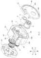
図1に示す印刷装置本体100は、図2A,2Bに示す印刷用カセット10と共に印刷装置を構成する。この印刷装置は、テープ状の印刷媒体に印刷を行う装置である。 [1. First embodiment]
[1-1. Configuration]
A printing device
本実施形態では、出力ギア21の軸方向を上下方向とし、上下方向と垂直な方向のうち出力ギア21と巻取スプール16とが並ぶ方向を前後方向とし、上下方向と前後方向との双方に垂直な方向を左右方向とする。In this embodiment, the axial direction of the
<印刷装置本体>
印刷装置本体100は、図1に示すように、カセット収納部101と、印刷ヘッド102と、プラテンローラ103と、プラテンギア104と、駆動シャフト105と、駆動源107と、筐体110とを備える。 <Printing device body>
As shown in FIG. 1 , the printing apparatus
(カセット収納部)
カセット収納部101は、印刷用カセット10が装着される凹部である。カセット収納部101は、印刷用カセット10の位置決め機能を有する。カセット収納部101は、筐体110に設けられている。 (Cassette storage section)
The
(印刷ヘッド)
印刷ヘッド102は、カセット収納部101の内部に配置されている。印刷ヘッド102は、個別に発熱が制御される複数の発熱素子を有する。 (Print head)
The
(プラテンローラ)
プラテンローラ103は、カセット収納部101の内部において、印刷ヘッド102と対向するように印刷ヘッド102の近傍に配置されている。プラテンローラ103は、印刷ヘッド102に対し、近づく方向又は離れる方向に揺動可能である。プラテンローラ103の回転軸心L1は、上下方向と平行である。 (Platen roller)
The
(プラテンギア)
プラテンギア104は、プラテンローラ103に連結されている。本実施形態では、プラテンギア104の回転軸心L2は、プラテンローラ103の回転軸心L1と同一線上に配置されている。プラテンギア104は、プラテンローラ103と共に揺動可能である。 (Platen gear)
The
(駆動シャフト)
駆動シャフト105は、印刷用カセット10の巻取スプール16と入力ギア22とに挿入される。駆動シャフト105は、巻取スプール16と入力ギア22とを回転させる。 (Drive shaft)
The
駆動シャフト105は、カセット収納部101の内部に配置されている。駆動シャフト105の回転軸心L3は、上下方向と平行である。駆動シャフト105は、駆動源107によって回転軸心L3を中心に回転する。The
(駆動源)
駆動源107は、駆動シャフト105を回転駆動させる。駆動源107としては、例えばモータとギアとを組み合わせた機構が使用できる。 (Drive source)
The driving
<印刷用カセット>
図2A,2Bに示す印刷用カセット10は、印刷媒体(つまり印刷用テープ11A)を備えている。印刷用カセット10は、印刷装置本体100への装着及び印刷装置本体100からの脱離が可能である。印刷用カセット10の交換により、印刷媒体の補給、及び印
刷媒体の種類(例えば、サイズ、色、材質等)の変更ができる。 <Printing cassette>
2A and 2B is equipped with a printing medium (i.e.,
印刷用カセット10は、印刷用テープカセット30と、補助テープカセット40とを備える。印刷用カセット10は、印刷用テープカセット30と、補助テープカセット40とが連結された状態で、印刷装置本体100へ装着される。The
(印刷用テープカセット)
図3A,3Bに示す印刷用テープカセット30は、印刷用テープ11Aの少なくとも一部を収容する印刷用テープケース35を備える。また、印刷用テープカセット30は、図4に示すように、第1ロール11と、第1供給スプール12と、スペーサフィルム13A,13Bとを備える。 (Printing tape cassette)
3A and 3B includes a
(第1ロール)
第1ロール11は、印刷が行われる印刷用テープ11Aを第1供給スプール12に巻回したものである。印刷用テープ11Aの表面には、印刷装置本体100の印刷ヘッド102及びインクリボン14A(補助テープの一例)によって印刷が行われる。 (First roll)
The
第1ロール11の上下方向の外側には、第1ロール11を挟むように2つのスペーサフィルム13A,13Bが配置されている。スペーサフィルム13A,13Bは、第1ロール11と第1ケース部31との間と、第1ロール11と第2ケース部32との間とに配置されている。Two
(第1供給スプール)
第1供給スプール12は、回転軸心L4周りに回転可能である。第1供給スプール12は、印刷装置本体100のプラテンローラ103による印刷用テープ11Aの搬送に伴って回転することで、印刷用テープ11Aを印刷ヘッド102に供給する。第1供給スプール12の回転軸心L4は、上下方向と平行であり、第1ロール11の巻回軸心と一致している。 (First supply spool)
The
(印刷用テープケース)
印刷用テープケース35は、第1ケース部31と、第2ケース部32と、第1ガイド面35A(図3A,3B参照)と、第1排出口35B(図3A,3B参照)とを有する。 (Printing tape case)
The
第1ケース部31は、印刷用テープケース35の上端部を構成している。第2ケース部32は、印刷用テープケース35の下端部を構成している。第2ケース部32は、第1ケース部31の下方に配置され、第1ケース部31と上下方向に連結されている。第1ロール11は、第1ケース部31と第2ケース部32とで囲まれた空間に配置されている。The
第1ケース部31は、第1側壁31Aと、第1切欠き31Bとを有する。第2ケース部32は、第2側壁32Aと、第2切欠き32Bと、第1位置決め部32Cとを有する。The
第1側壁31A及び第2側壁32Aは、印刷用テープケース35の外面のうち、第1ロール11を周方向に取り囲む側面を構成している。第1切欠き31Bは、第1側壁31Aの前方部に設けられている。第2切欠き32Bは、第2側壁32Aの前方部に設けられている。第1切欠き31B及び第2切欠き32Bは、互いに連結されて印刷用テープ11Aの第1排出口35Bを構成する。The
図2A,2Bに示すように、印刷用テープケース35の側面の一部は、印刷用テープケース35の第1排出口35Bから排出された印刷用テープ11Aをガイドする第1ガイド面35Aを構成している。As shown in Figures 2A and 2B, a portion of the side surface of the
第1排出口35Bは、印刷用テープケース35の側面に設けられると共に、印刷用テープ11Aを印刷用テープケース35の外部へ排出する。第1排出口35Bから第1ロール11の径方向に排出された印刷用テープ11Aは、上下方向と平行な中心軸を有する螺旋状に第1ガイド面35Aに巻回されながら、第1排出口35Bから下方に(つまり補助テープカセット40に向かって)搬送される。The
図3Aに示すように、第1位置決め部32Cは、印刷用テープケース35がカセット収納部101に挿入された状態で下方に位置する補助テープカセット40と、対向及び接触する第1連結面35Cに設けられた孔である。第1位置決め部32Cは、印刷用テープケース35の補助テープカセット40に対する位置決めをする。第1位置決め部32Cには、補助テープカセット40の第2位置決め部41Eが挿入される。As shown in FIG. 3A, the
第1連結面35Cは、印刷用テープケース35の外面のうち、上下方向と交差する(具体的には直交する)平面である。第1連結面35Cには、補助テープカセット40が配置可能である。The first connecting
(補助テープカセット)
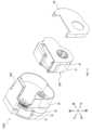
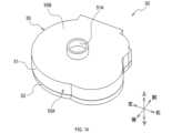
図5A,5Bに示す補助テープカセット40は、印刷用テープカセット30に着脱可能である。補助テープカセット40は、インクリボン14Aの少なくとも一部及び駆動伝達部20の少なくとも一部を収容する補助テープケース45を備える。 (auxiliary tape cassette)
5A and 5B is detachably attached to the
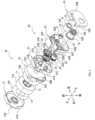
本実施形態の補助テープカセット40は、ギアを収容するギアカセットでもある。補助テープカセット40は、図4に示すように、第2ロール14と、第2供給スプール15と、巻取スプール16と、クラッチバネホルダ17と、駆動伝達部20とを備える。The
(第2ロール)
第2ロール14は、印刷用テープ11Aの印刷に用いられるインクリボン14Aを第2供給スプール15に巻回したものである。 (Second roll)
The
インクリボン14Aは、ヘッド開口42Bにおいて、搬送される印刷用テープ11Aと重ね合わされ、印刷ヘッド102による印刷に供される。印刷に使用されたインクリボン14Aは、巻取スプール16に巻き取られる。The
第2ロール14には、クラッチバネホルダ17に保持されたクラッチバネ(図示省略)によって回転抵抗が付される。第2ロール14の少なくとも一部は、上下方向において、第1ロール11と重なる位置に配置されている。A clutch spring (not shown) held by a
(第2供給スプール)
第2供給スプール15は、回転軸心L5周りに回転可能である。第2供給スプール15の回転軸心L5は、第1供給スプール12の回転軸心L4と平行、つまり上下方向と平行であり、第2ロール14の巻回軸心と一致している。第2供給スプール15は、インクリボン14Aの巻取スプール16による巻き取りに伴って回転することで、インクリボン14Aをヘッド開口42Bに供給する。 (Second supply spool)
The
(巻取スプール)
巻取スプール16は、回転軸心L6周りに回転可能である。巻取スプール16の回転軸心L6は、第2供給スプール15の回転軸心L5と平行である。 (Take-up spool)
The take-up
巻取スプール16は、円筒状であり、内周面16Aで規定される中空部を有する。巻取
スプール16の内周面16Aにはスプライン歯16Bが設けられている。スプライン歯16Bには、印刷装置本体100の駆動シャフト105が連結される。巻取スプール16は、駆動シャフト105によって回転され、印刷に使用されたインクリボン14Aを巻き取る。 The take-up
(駆動伝達部)
駆動伝達部20は、印刷用カセット10が印刷装置本体100に装着された際に、駆動シャフト105から伝達される駆動源107の駆動力をプラテンローラ103に伝達すると共に、プラテンローラ103を印刷用カセット10ごとに設定された回転速度で回転させる。 (Drive transmission part)
When the
駆動伝達部20は、出力ギア21と、入力ギア22と、アイドルギア23とを有する。駆動伝達部20は、第2ロール14よりも上方(つまり印刷用テープカセット30の近く)に配置されている。つまり、出力ギア21及び入力ギア22は、補助テープケース45内において第2ロール14と上下方向に離れて配置されている。The
(出力ギア)
出力ギア21は、印刷用テープ11Aの搬送に供される駆動力を外部に出力するための外歯ギアである。具体的には、出力ギア21は、印刷装置本体100のプラテンギア104に駆動力を出力する。出力ギア21の回転軸心L7は、第2供給スプール15の回転軸心L5と平行である。出力ギア21は、ヘッド開口42Bと連通する空間に一部が露出している。 (Output gear)
The
出力ギア21は、印刷用カセット10が印刷装置本体100に装着された状態(つまり、補助テープケース45がカセット収納部101に収納された状態)で、ヘッド開口42Bと連通した空間においてプラテンギア104に係合する。When the
(入力ギア)
入力ギア22は、アイドルギア23を介して出力ギア21と間接的に係合し、駆動力を出力ギア21に伝達する。 (Input gear)
The
入力ギア22は、外歯ギア22Aと、外歯ギア22Aの一方の側面に固定されると共に、内周面にスプライン歯を有する円筒状の内歯ギアであるスプール22Bとを有する。外歯ギア22Aは、スプール22Bに入力された駆動源107の駆動力によってスプール22Bと一体回転する。The
入力ギア22の回転軸心L8(つまり、外歯ギア22Aの回転軸心、及びスプール22Bの回転軸心)は、巻取スプール16の回転軸心L6と同一線上に配置されている。入力ギア22の少なくとも一部は、上下方向において、第1ロール11と重なる位置に配置されている。The rotation axis L8 of the input gear 22 (i.e., the rotation axis of the
入力ギア22の回転軸心L8は、上下方向において、巻取スプール16の中空部と重なる。また、入力ギア22のスプール22Bの下端部は、巻取スプール16の中空部に上方から挿入されている。The rotation axis L8 of the
そのため、印刷用カセット10が印刷装置本体100に装着された状態では、駆動シャフト105が巻取スプール16と入力ギア22とに同時に挿通される。その結果、入力ギア22は、巻取スプール16と直接連結はされないが、巻取スプール16と共に駆動シャフト105によって回転される。Therefore, when the
(アイドルギア)
アイドルギア23は、入力ギア22と出力ギア21とに駆動連結され(つまり係合し)、入力ギア22に入力された駆動力を出力ギア21に伝達する。つまり、駆動シャフト105は、入力ギア22及びアイドルギア23を介して、出力ギア21に間接的に駆動力を入力する。 (Idol Gear)
The
アイドルギア23は、入力ギア22に係合した上流ギア23Aと、出力ギア21に係合した下流ギア23Bとが同軸上に並んで配置された段ギアである。下流ギア23Bは、上流ギア23Aよりも径が小さい。また、上流ギア23Aは、上下方向において、下流ギア23Bよりも印刷用テープカセット30に近い位置(つまり上方)に配置されている。The
アイドルギア23は、入力ギア22に入力された駆動力の回転速度を減速して出力ギア21に伝達する。つまり、駆動伝達部20は、入力ギア22の回転速度を出力ギア21の回転速度で除した伝達比を減速比とする減速機構を含んでいる。The
(補助テープケース)
補助テープケース45は、第3ケース部41と、第4ケース部42と、第5ケース部43と、第2ガイド面45A(図2A,2B参照)とを有する。 (auxiliary tape case)
The
第3ケース部41は、補助テープケース45の上端部を構成している。第5ケース部43は、補助テープケース45の下端部を構成している。第4ケース部42は、第3ケース部41の下方かつ第5ケース部43の上方に配置され、第3ケース部41及び第5ケース部43と上下方向に連結されている。The
第2ロール14、第2供給スプール15及び巻取スプール16は、第4ケース部42と第5ケース部43とで囲まれた空間に配置されている。出力ギア21の一部、入力ギア22、及びアイドルギア23は、第3ケース部41と第4ケース部42とで囲まれた空間に配置されている。The
第3ケース部41は、第3側壁41Aと、第1ギア支持部41Bと、第2ギア支持部41Cと、第3ギア支持部41Dと、第2位置決め部41E(図5B参照)とを有する。
第3側壁41Aは、補助テープケース45の外面のうち、印刷用テープケース35の側面と連続する側面を構成している。 The
The
第1ギア支持部41Bは、出力ギア21を回転可能に支持する。第2ギア支持部41Cは、入力ギア22を回転可能に支持する。第3ギア支持部41Dは、アイドルギア23を回転可能に支持する。The first
図5Bに示す第2位置決め部41Eは、補助テープケース45がカセット収納部101に挿入された状態で上方に位置する印刷用テープカセット30と、対向及び接触する第2連結面45Bに設けられている。The
第2連結面45Bは、補助テープケース45の外面のうち、上下方向と交差する(具体的には直交する)平面であり、印刷用テープケース35の第1連結面35Cと平行である。第2連結面45Bには、印刷用テープカセット30が配置可能である。The second connecting
第2位置決め部41Eは、第2連結面45Bから上方に突出する筒状又は柱状の部位である。補助テープカセット40と印刷用テープカセット30との連結時に、第2位置決め部41Eが印刷用テープケース35の第1位置決め部32Cに挿入されることで、印刷用テープカセット30に対する補助テープカセット40の前後方向及び左右方向の位置決め
が行われる。 The
図4に示す第4ケース部42は、第4側壁42Aと、ヘッド開口42Bと、第2排出口42Cと、ガイド内壁42Dと、第1規制部42Eと、天井壁42Fとを有する。
第4側壁42Aは、補助テープケース45の外面のうち、第2ロール14を周方向に取り囲む側面を構成している。 The
The
ヘッド開口42Bは、第4側壁42Aの一部を切り欠いた部位である。ヘッド開口42Bは、印刷用カセット10が印刷装置本体100に装着された状態で、内部に印刷ヘッド102が配置される空間である。The
ヘッド開口42Bにおいて、印刷ヘッド102による印刷用テープ11Aの印刷が行われる。ヘッド開口42Bは、印刷ヘッド102が下方から挿入可能なように、補助テープカセット40の下方に開口している。ヘッド開口42Bにおいて、印刷用テープ11A及びインクリボン14Aが左右方向に架け渡される。In the
第2排出口42Cは、印刷が行われた印刷用テープ11Aを印刷用カセット10の外部へ排出する。つまり、第2排出口42Cは、印刷用テープ11Aを補助テープケース45の内部から外部へ排出する。印刷後の印刷用テープ11Aは、第2排出口42Cから印刷装置の外部に排出される。The
ガイド内壁42Dは、補助テープケース45内において左右方向に印刷用テープ11Aをガイドする(つまり後方から印刷用テープ11Aに接触する)前面を有する板状の部位である。ガイド内壁42Dは、印刷用テープ11Aを第2排出口42Cに向けてガイドする第2ガイド面45Aの一部を構成している。The guide
ガイド内壁42Dは、第4側壁42Aから連続して設けられている。また、ガイド内壁42Dは、印刷用テープ11Aの排出方向においてヘッド開口42Bよりも上流側、かつ、ヘッド開口42Bよりも前方に配置されている。The guide
ガイド内壁42Dは、少なくとも一部が上下方向において第2排出口42Cと同じ位置に配置されている。つまり、ガイド内壁42Dの少なくとも一部は、上下方向と直交する方向において第2排出口42Cと重なっている。ガイド内壁42D上において、印刷用テープ11Aは、上下方向と直交する方向(具体的には左右方向)に搬送される。At least a portion of the guide
第1規制部42Eは、ガイド内壁42Dによって構成される第2ガイド面45Aに沿って搬送される印刷用テープ11Aの幅方向の移動を規制する。具体的には、第1規制部42Eは、ガイド内壁42Dの上方に配置され、上下方向と直交する下面を有する。The
天井壁42Fは、ガイド内壁42Dの前方に、ガイド内壁42Dと離れて配置されている。天井壁42Fは、ガイド内壁42Dとの間に、印刷用テープ11Aの搬送路を構成している。天井壁42Fは、第1規制部42Eと連結されている。天井壁42Fの内面(つまり後面)は、第2ガイド面45A(つまりガイド内壁42D)と対向するように配置された規制面を構成している。The
第5ケース部43は、第5側壁43Aと、第2規制部43Bとを有する。
第5側壁43Aは、第4ケース部42の第4側壁42Aと共に、第2ロール14を周方向に取り囲む補助テープケース45の側面を構成している。 The
The
第2規制部43Bは、第2ガイド面45Aに沿って搬送される印刷用テープ11Aの幅
方向の移動を規制する。具体的には、第2規制部43Bは、第4ケース部42のガイド内壁42Dの下方に配置され、上下方向と直交する上面を有する。第2規制部43Bは、第4ケース部42の第1規制部42Eと上下方向に対向している。 The
ガイド内壁42D、天井壁42F、第1規制部42E及び第2規制部43Bは、図2Bに示すように、補助テープケース45の第2ガイド面45Aに沿って搬送される印刷用テープ11Aが内部を通過する空間を有するアーム部45Cを構成する。アーム部45Cを通過した印刷用テープ11Aは、ヘッド開口42Bに供給される。As shown in FIG. 2B, the guide
アーム部45C内では、ガイド内壁42D及び天井壁42Fによって印刷用テープ11Aの前後方向(つまり厚み方向)の移動が規制されると共に、第1規制部42E及び第2規制部43Bによって印刷用テープ11Aの上下方向(つまり幅方向)の移動が規制される。Inside the
図2A,2Bに示すように、補助テープケース45の側面の一部は、補助テープケース45の外部から(つまり印刷用テープカセット30から)供給される印刷用テープ11Aを第2排出口42Cに向けてガイドする第2ガイド面45Aを構成している。第2ガイド面45Aは、印刷用テープケース35の第1ガイド面35Aによってガイドされた印刷用テープ11Aをヘッド開口42Bに向けてさらにガイドする。As shown in Figures 2A and 2B, a portion of the side surface of the
<印刷装置本体による印刷用テープの搬送及び印刷>
印刷用カセット10の印刷装置本体100への装着時において、印刷用テープ11Aは、上下方向と平行な中心軸周りの回転角度(つまり上下方向から視た印刷用テープケース35及び補助テープケース45への巻き角)が180°以上となる螺旋部分11Bを構成するように、印刷用テープケース35の第1ガイド面35A及び補助テープケース45の第2ガイド面45Aに巻回される。 <Transportation and printing of printing tape by the printing device body>
When the
搬送される印刷用テープ11Aの螺旋部分11Bは、印刷用テープケース35の側面と補助テープケース45の側面とに跨って巻き掛けられる。具体的には、螺旋部分11Bは、印刷用テープケース35の第1排出口35Bからアーム部45Cの内部まで延伸している。The
第1ガイド面35A及び第2ガイド面45Aは、それぞれ、ヘッド開口42Bよりも印刷用テープ11Aの排出方向における上流側において螺旋部分11Bの少なくとも一部をガイドする曲面を有する。The
具体的には、第1ガイド面35Aは、その全体が曲面で構成されている。また、第2ガイド面45Aは、アーム部45C内(つまりガイド内壁42Dの前面)を除いた部位が曲面で構成されている。Specifically, the
また、第1ガイド面35Aの曲面の少なくとも一部の曲率半径、及び第2ガイド面45Aの曲面の少なくとも一部の曲率半径は、それぞれ、第2ロール14の外径の1/2よりも大きい。In addition, the radius of curvature of at least a portion of the curved surface of the
このように印刷用テープ11Aがガイド面に巻き掛けられた印刷用カセット10が印刷装置本体100に装着された状態で、印刷ヘッド102は、ヘッド開口42Bにおいて、印刷用テープ11A及びインクリボン14Aと前後方向に重なる位置に配置される。When the
印刷用テープ11Aは、プラテンローラ103によってヘッド開口42Bに搬送されると共に、プラテンローラ103によってインクリボン14Aを介して発熱素子が発熱した
印刷ヘッド102に押し付けられる。これにより、インクリボン14Aの表面に配置されたインクの一部が印刷用テープ11Aに転写され、印刷用テープ11Aに文字、記号等が印刷される。 The
プラテンローラ103は、印刷後の印刷用テープ11Aを印刷用カセット10内から外部に向けて搬送する。プラテンローラ103は、出力ギア21と係合されたプラテンギア104によって回転する。プラテンローラ103及びプラテンギア104は、印刷用カセット10と離れた位置と、プラテンギア104が出力ギア21に係合した位置との間で揺動可能である。The
印刷用カセット10の補助テープケース45がカセット収納部101に挿入された状態では、駆動シャフト105が入力ギア22に係合すると共にプラテンギア104が出力ギア21に係合する。When the
具体的には、駆動シャフト105が印刷用カセット10の巻取スプール16及び入力ギア22に挿入された状態で、プラテンローラ103及びプラテンギア104が印刷用カセット10のヘッド開口42Bに向けて揺動することで、プラテンギア104が出力ギア21に係合する。Specifically, when the
印刷用カセット10が装着された状態で駆動シャフト105により入力ギア22が回転されることで出力ギア21が回転される。さらに、出力ギア21の回転によりプラテンギア104が回転し、プラテンギア104の回転によりプラテンローラ103が回転する。When the
<第1実施形態の変形例>
図6A,6Bに示す印刷用カセット10Aは、印刷用テープカセット30Aと、補助テープカセット40Aとを有する。印刷用カセット10Aは、図2A,2Bの印刷用カセット10において補助テープカセット40に設けられたアーム部45Cを、印刷用テープカセット30Aにアーム部35Dとして設けたものである。 <Modification of the First Embodiment>
The
図7Aに示すように、印刷用テープカセット30Aのアーム部35Dは、内部を印刷用テープ11Aが通過可能なスリット状の搬送路35Eを有する。アーム部35Dは、図7Bに示す補助テープカセット40Aのヘッド開口42Bの前方(具体的には、第4側壁42Aの前方)に重ねて配置される。アーム部35Dは、第1ケース部31が有する下方に突出する板部と、第2ケース部32が有する下方に突出する板部とによって構成されている。As shown in FIG. 7A, the
[1-2.効果]
以上詳述した実施形態によれば、以下の効果が得られる。
(1a)印刷用テープカセット30の第1ガイド面35A及び補助テープカセット40の第2ガイド面45Aそれぞれによって、ヘッド開口42Bに送られる印刷用テープ11Aのよじれ等の不具合が抑制される。そのため、印刷用テープ11Aを補助テープカセット40に設けられたヘッド開口42Bに適切に搬送できる。 [1-2. Effects]
According to the embodiment described above in detail, the following effects can be obtained.
(1a) The
(1b)印刷用テープカセット30の第1位置決め部32Cと補助テープカセット40の第2位置決め部41Eとによって、印刷用テープケース35と補助テープケース45との位置ずれが抑制できる。その結果、印刷用テープ11Aの搬送の安定性を高めることができる。(1b) The
(1c)駆動伝達部20が補助テープケース45内において第2ロール14と上下方向に離れて配置されることで、印刷用テープ11Aをヘッド開口42Bに適切に搬送しつつ
、補助テープケース45の前後方向及び左右方向の大きさを低減できる。 (1c) By positioning the
(1d)第1規制部42E及び第2規制部43Bによって、印刷用テープ11Aのヘッド開口42Bへの搬送の安定性を高めることができる。
(1e)天井壁42Fの規制面によって、印刷用テープ11Aのヘッド開口42Bへの搬送の安定性を高めることができる。 (1d) The
(1e) The regulating surface of the
[2.第2実施形態]
[2-1.構成]
図8A,8Bに示す印刷用カセット210は、第1実施形態の印刷用カセット10に代えて、図1の印刷装置本体100に装着される。印刷用カセット210は、印刷用テープカセット230と、補助テープカセット240とを備える。 [2. Second embodiment]
[2-1. Configuration]
8A and 8B is mounted in the printing apparatus
(印刷用テープカセット)
図9A,9Bに示す印刷用テープカセット230は、印刷用テープ11A及び駆動伝達部20を収容する印刷用テープケース235を有する。本実施形態の印刷用テープカセット230は、ギアを収容するギアカセットでもある。 (Printing tape cassette)
9A and 9B has a
印刷用テープカセット230は、第1実施形態の印刷用テープカセット30に、第1実施形態の補助テープカセット40の第3ケース部41を第3ケース部33として追加すると共に、第1実施形態の駆動伝達部20を印刷用テープケース235内に配置したものである。印刷用テープカセット230におけるその他の構成は、第1実施形態の印刷用テープカセット30と同じである。The
第3ケース部33は、第2ケース部32の下方に連結され、印刷用テープケース235の下端部を構成している。出力ギア21の一部、入力ギア22、及びアイドルギア23は、第2ケース部32と第3ケース部33とで囲まれた空間に配置されている。The
つまり、出力ギア21及び入力ギア22は、印刷用テープケース235内において、第1ケース部31と第2ケース部32とで囲まれた空間に配置されている第1ロール11と上下方向に離れて配置されている。In other words, the
第3ケース部33の下面は、補助テープカセット240が配置可能な第1連結面35Cを構成する。第1連結面35Cには、入力ギア22が上下方向に挿通される挿通孔33Aが設けられている。印刷用テープケース235は、第1連結面35Cから突出した入力ギア22によって構成される、補助テープカセット240に対する位置決め部を有する。The bottom surface of the
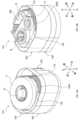
(補助テープカセット)
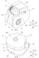
図10A,10Bに示す補助テープカセット240は、第1実施形態の補助テープカセット40から、第3ケース部41及び駆動伝達部20を取り外したものである。 (auxiliary tape cassette)
An
補助テープカセット240は、第4ケース部42と第5ケース部43とを有する補助テープケース245を備える。補助テープカセット240におけるその他の構成は、第1実施形態の補助テープカセット40と同じである。The
本実施形態では、第4ケース部42の上面は、印刷用テープカセット230が配置可能な第2連結面45Bを構成している。第2連結面45Bには、印刷用テープカセット230の入力ギア22が挿入可能な開口42Gが設けられている。開口42Gは、印刷用テープカセット230に対する補助テープカセット240の位置決めを行う位置決め部を構成している。In this embodiment, the top surface of the
<第2実施形態の変形例>
図11に示すように、本実施形態の印刷用カセット210は、補助テープカセット240の下方に配置されるカセットカバー46を備えてもよい。 <Modification of the second embodiment>
As shown in FIG. 11 , the
図11の印刷用テープカセット230Aは、図7Aの印刷用テープカセット30Aと同様のアーム部35Dと、補助テープカセット240を収納する空間を形成する枠部34を備える。カセットカバー46は、枠部34の蓋を構成する。The
[2-2.効果]
以上詳述した実施形態によれば、以下の効果が得られる。
(2a)第1実施形態と同様の利点を有したまま、印刷用カセット210を、インクリボン14Aが単体で交換可能な構成とすることができる。 [2-2. Effects]
According to the embodiment described above in detail, the following effects can be obtained.
(2a) While retaining the same advantages as the first embodiment, the
[3.第3実施形態]
[3-1.構成]
図12A,12Bに示す印刷用カセット310は、第1実施形態の印刷用カセット10に代えて、図1の印刷装置本体100に装着される。印刷用カセット310は、印刷用テープカセット30と、補助テープカセット240と、ギアカセット50とを備える。 [3. Third embodiment]
[3-1. Configuration]
12A and 12B is installed in the printing device
印刷用カセット310における印刷用テープカセット30は、第1実施形態と同じものである。印刷用カセット310における補助テープカセット240は、第2実施形態と同じものである。The
(ギアカセット)
図13に示すように、ギアカセット50は、印刷用テープカセット30と補助テープカセット240との間に配置される。ギアカセット50は、印刷用テープカセット30及び補助テープカセット240に着脱可能である。 (Gear cassette)
13, the
図14に示すように、ギアカセット50は、第1実施形態の駆動伝達部20を収容するギアケース55を有する。ギアケース55は、第6ケース部51と第7ケース部52と、第3ガイド面55Aとを有する。As shown in FIG. 14, the
第6ケース部51は、ギアケース55の上端部を構成している。第7ケース部52は、第6ケース部51の下方に連結され、ギアケース55の下端部を構成している。出力ギア21の一部、入力ギア22、及びアイドルギア23は、第6ケース部51と第7ケース部52とで囲まれた空間に配置されている。The
第6ケース部51は、ギアケース55がカセット収納部101に挿入された状態で上方に位置する印刷用テープカセット30と、対向及び接触する第3連結面55Bに設けられた第3位置決め部51Aを有する。The
第3位置決め部51Aは、第3連結面55Bから上方に突出する筒状又は柱状の部位である。ギアカセット50と印刷用テープカセット30との連結時に、第3位置決め部51Aは印刷用テープケース35の第1位置決め部32Cに挿入される。The
図13に示すように、第7ケース部52の下面は、補助テープカセット240が配置可能な第4連結面55Cを構成する。第4連結面55Cには、入力ギア22が上下方向に挿通される挿通孔52Aが設けられている。ギアケース55は、第4連結面55Cから突出した入力ギア22によって構成される第4位置決め部を有する。As shown in FIG. 13, the bottom surface of the
図12A,12Bに示すように、第6ケース部51及び第7ケース部52によって構成されるギアケース55の側面の一部は、印刷用テープカセット30の第1ガイド面35Aによってガイドされた印刷用テープ11Aを、補助テープカセット240の第2ガイド面45Aに向けてさらにガイドする第3ガイド面55Aを構成している。第3ガイド面55Aは、印刷用テープ11Aの螺旋部分11Bに接触する。As shown in Figures 12A and 12B, a part of the side of the
[3-2.効果]
以上詳述した実施形態によれば、以下の効果が得られる。
(3a)第1実施形態と同様の利点を有したまま、印刷用カセット310を、印刷用テープ11A、駆動伝達部20及びインクリボン14Aがそれぞれ単体で交換可能な構成とすることができる。 [3-2. Effects]
According to the embodiment described above in detail, the following effects can be obtained.
(3a) While retaining the same advantages as the first embodiment, the
[4.第4実施形態]
[4-1.構成]
図15A,15Bに示す印刷用カセット410は、第1実施形態の印刷用カセット10に代えて、図1の印刷装置本体100に装着される。印刷用カセット410は、印刷用テープカセット430と、補助テープカセット440とを備える。 [4. Fourth embodiment]
[4-1. Configuration]
15A and 15B is mounted in the printing apparatus
なお、図15Aは、印刷用テープカセット430の第1ケース部431を取り外した状態を示している。図15Bは、補助テープカセット440の第3ケース部441を取り外した状態を示している。Note that Figure 15A shows the state where the
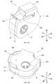
(印刷用テープカセット)
図16A,16Bに示す印刷用テープカセット430は、印刷用テープ11Aを収容する印刷用テープケース435を有する。印刷用テープケース435の内部に収容されるパーツは、第1実施形態の印刷用カセット10と同じである。 (Printing tape cassette)
16A and 16B has a
印刷用テープケース435は、第1ケース部431と、第2ケース部432と、第1ガイド面435Aと、第1排出口435Bとを有する。第1ケース部431は、印刷用テープケース435の上端部を構成している。第2ケース部432は、第1ケース部431の下方に連結され、印刷用テープケース435の下端部を構成している。The
第2ケース部432は、第1実施形態と同様の第1連結面35Cに設けられた第1位置決め部32Cを有する。また、第2ケース部432は、第1ガイド面435Aを構成する内壁432Aと、第1排出口435Bを構成する開口とを有する。内壁432Aは、第1ロール11を径方向外側から囲っている。The
第1排出口435Bは、第1連結面35Cに設けられており、第1連結面35Cと交差する方向(つまり上下方向)において印刷用テープ11Aを印刷用テープケース435の外部へ排出する。The
図15Aに示すように、第1ガイド面435Aは、第1ロール11から引き出された印刷用テープ11Aを第1排出口435Bへ向けてガイドする。印刷用テープ11Aは、螺旋部分11Bを構成しながら第1ガイド面435Aに第1ロール11の径方向外側から巻回される。As shown in FIG. 15A, the
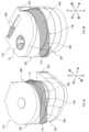
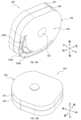
(補助テープカセット)
図17A,17Bに示す補助テープカセット440は、インクリボン14A及び駆動伝達部20を収容する補助テープケース445を有する。補助テープケース445の内部に
収容されるパーツは、第1実施形態の印刷用カセット10と同じである。 (auxiliary tape cassette)
17A and 17B has an
補助テープケース445は、第3ケース部441と、第4ケース部442と、第5ケース部443と、第2ガイド面445Aと、第1案内開口445Dと、第2案内開口445Eとを有する。The
第3ケース部441は、補助テープケース445の上面(つまり第2連結面445B)を構成している。第5ケース部443は、補助テープケース445の下端部を構成している。第4ケース部442は、第5ケース部443の上方に連結されている。The
第3ケース部441は、第1実施形態と同様の第2位置決め部41Eを有する。また、図18に示すように、第3ケース部441は、駆動伝達部20を支持している。第3ケース部441は、第4ケース部442の内部空間を上方から塞ぐように、第4ケース部442の外壁442Aの内側に嵌め込まれている。The
第4ケース部442は、第1実施形態と同様のヘッド開口42Bと、第2排出口42Cと、ガイド内壁42Dと、第1規制部42Eと、天井壁42Fとを有する。また、第4ケース部442は、外壁442Aと、内壁442Bとを有する。The
内壁442Bは、第2ロール14、第2供給スプール15及び巻取スプール16を第2ロール14の径方向外側から囲っている。内壁442Bの外面の一部は、第2ガイド面445Aを構成している。The
外壁442Aは、内壁442Bを外側から囲んでいる。図17Bに示すように、補助テープケース445の上端部において、外壁442Aと内壁442Bとの間の空間に連通する第1案内開口445Dが、第3ケース部441と第4ケース部442とによって形成されている。The
第1案内開口445Dは、印刷用テープカセット430と連結される第2連結面445B(第1外面の一例)に設けられている。印刷用テープケース435の第1排出口435Bから排出された印刷用テープ11Aは、第1案内開口445Dから補助テープケース445内に搬送される。The
図15Bに示すように、補助テープケース445内に搬送された印刷用テープ11Aは、螺旋部分11Bを構成しながら第2ガイド面445Aに第2ロール14の径方向外側から巻回される。As shown in FIG. 15B, the
図18に示す第5ケース部443は、第1実施形態と同様の第2規制部43Bを有する。また、第5ケース部443は、第2案内開口445Eを構成する開口を有する。第2案内開口445Eは、補助テープケース445において第2連結面445Bと共に第2ロール14を上下方向に挟む底面445C(第2外面の一例)に設けられている。The
第2案内開口445Eは、第4ケース部442の外壁442Aと内壁442Bとの間の空間と連通している。また、第2案内開口445Eの少なくとも一部は、第1案内開口445Dと対向している。さらに、第2案内開口445Eは、第2ガイド面445Aに沿って、第4ケース部442における印刷用テープ11Aの搬送路と上下方向に重なるように、アーム部45C(つまりガイド内壁42D)と重なる位置まで延伸している。The second guide opening 445E communicates with the space between the
そのため、第1案内開口445Dから補助テープケース445内に挿通された印刷用テープ11Aを第2案内開口445Eから補助テープケース445の下側に引き出しながら
、補助テープケース445内の搬送路に配置することができる。 Therefore, the
なお、第2案内開口445Eは、上下方向において第2ロール14の全体とは重なっていない。つまり、第2案内開口445Eは、第2ロール14が第5ケース部443を下方に通過して補助テープケース445から脱落することがない形状に形成されている。The second guide opening 445E does not overlap the entire
[4-2.効果]
以上詳述した実施形態によれば、以下の効果が得られる。
(4a)第1ガイド面435A及び第2ガイド面445Aがそれぞれケースの内面に設けられることで、印刷用テープ11Aの保護を図ることができる。 [4-2. Effects]
According to the embodiment described above in detail, the following effects can be obtained.
(4a) The
(4b)第2案内開口445Eによって、印刷用テープカセット430から印刷用テープ11Aを引き出しながら、補助テープケース445内の搬送路に印刷用テープ11Aを配置できる。(4b) The second guide opening 445E allows the
[5.他の実施形態]
以上、本開示の実施形態について説明したが、本開示は、上記実施形態に限定されることなく、種々の形態を採り得ることは言うまでもない。 5. Other embodiments
Although the embodiments of the present disclosure have been described above, it goes without saying that the present disclosure is not limited to the above-described embodiments and can take various forms.
(5a)上記実施形態の印刷装置は、インクリボンを用いて印刷するものに限定されない。印刷装置は、印刷用テープの代わりとして帯状の感熱紙を用いてもよい。この場合、補助テープとしては、例えばラミネートテープが用いられる。(5a) The printing device of the above embodiment is not limited to one that prints using an ink ribbon. The printing device may use a strip of thermal paper instead of printing tape. In this case, for example, a laminate tape is used as the auxiliary tape.
(5b)上記実施形態の印刷用カセットは、必ずしも印刷用テープカセットを備えなくてもよい。例えば、図19に示す印刷用カセット510は、第1ロール11を支持する第1ケース部531と、第1ケース部531と共に駆動伝達部20を収容する第2ケース部532と、第2ケース部532と共に第2ロール14を収容する第3ケース部533とを備える。(5b) The printing cassette of the above embodiment does not necessarily have to include a printing tape cassette. For example, the
図19の印刷用カセット510では、第1ケース部531と第2ケース部532と第3ケース部533とで構成される補助テープカセットに第1ロール11を着脱できる。そのため、印刷用テープカセットを交換することなく、第1ロール11のみの交換が可能である。In the
図19の印刷用カセット510では、第1ケース部531の側面によって第1ガイド面535Aが構成され、第2ケース部532の側面によって第2ガイド面545Aが構成される。In the
(5c)上記実施形態の印刷用カセットにおいて、印刷用テープカセット及び補助テープカセットのいずれか一方のケースの内面にガイド面が構成され、他方のケースの外面にガイド面が構成されてもよい。(5c) In the printing cassette of the above embodiment, a guide surface may be formed on the inner surface of the case of either the printing tape cassette or the auxiliary tape cassette, and a guide surface may be formed on the outer surface of the other case.
例えば、図20A及び図20Bに示す印刷用カセット610では、印刷用テープカセット630においてケースの内面に第1ガイド面635Aが設けられる一方で、補助テープカセット640においてはケースの外面に第2ガイド面645Aが設けられている。For example, in the
第1ガイド面635Aにガイドされて印刷用テープカセット630の第1排出口635Bから下方に排出された印刷用テープ11Aは、第2ガイド面645Aにガイドされつつアーム部45Cを通過してヘッド開口42Bへ搬送される。The
また例えば、図21A及び図21Bに示す印刷用カセット710では、印刷用テープカセット730においてケースの外面に第1ガイド面735Aが設けられる一方で、補助テープカセット740においてはケースの内面に第2ガイド面745Aが設けられている。For example, in the
印刷用テープカセット730の第1排出口735Bから排出された印刷用テープ11Aは、第1ガイド面735A及び第2ガイド面745Aにガイドされてヘッド開口42Bへ搬送される。The
(5d)上記実施形態の印刷用カセットは、アーム部を必ずしも有しなくてもよい。つまり、印刷用テープカセット及び補助テープカセットのケースは、必ずしもガイド面に沿って搬送される印刷用テープの幅方向の移動を規制する規制部及びガイド面と対向する規制面を有しなくてもよい。(5d) The printing cassette of the above embodiment does not necessarily have to have an arm portion. In other words, the cases of the printing tape cassette and the auxiliary tape cassette do not necessarily have to have a regulating portion that regulates the widthwise movement of the printing tape transported along the guide surface and a regulating surface that faces the guide surface.
(5e)上記実施形態における1つの構成要素が有する機能を複数の構成要素として分散させたり、複数の構成要素が有する機能を1つの構成要素に統合したりしてもよい。また、上記実施形態の構成の一部を省略してもよい。また、上記実施形態の構成の少なくとも一部を、他の上記実施形態の構成に対して付加、置換等してもよい。なお、特許請求の範囲に記載の文言から特定される技術思想に含まれるあらゆる態様が本開示の実施形態である。(5e) The function of one component in the above embodiments may be distributed among multiple components, or the functions of multiple components may be integrated into one component. In addition, part of the configuration of the above embodiments may be omitted. In addition, at least part of the configuration of the above embodiments may be added to or substituted for the configuration of another of the above embodiments. All aspects included in the technical idea identified from the wording of the claims are embodiments of the present disclosure.
10…印刷用カセット、11…第1ロール、11A…印刷用テープ、
11B…螺旋部分、14…第2ロール、14A…インクリボン、16…巻取スプール、
20…駆動伝達部、21…出力ギア、22…入力ギア、23…アイドルギア、
30…印刷用テープカセット、32C…第1位置決め部、35…印刷用テープケース、
35A…第1ガイド面、35B…第1排出口、35C…第1連結面、
40…補助テープカセット、41E…第2位置決め部、42B…ヘッド開口、
42C…第2排出口、42E…第1規制部、42F…天井壁、43B…第2規制部、
45…補助テープケース、45A…第2ガイド面、45B…第2連結面、
50…ギアカセット、55…ギアケース、100…印刷装置本体、
101…カセット収納部、102…印刷ヘッド、103…プラテンローラ。 10: Printing cassette, 11: First roll, 11A: Printing tape,
11B: spiral portion; 14: second roll; 14A: ink ribbon; 16: take-up spool;
20: drive transmission portion, 21: output gear, 22: input gear, 23: idle gear,
30: printing tape cassette, 32C: first positioning portion, 35: printing tape case,
35A...first guide surface, 35B...first discharge port, 35C...first connection surface,
40: auxiliary tape cassette; 41E: second positioning portion; 42B: head opening;
42C...Second discharge port, 42E...First regulation part, 42F...Ceiling wall, 43B...Second regulation part,
45...auxiliary tape case, 45A...second guide surface, 45B...second connection surface,
50: gear cassette, 55: gear case, 100: printing device main body,
101: cassette storage section, 102: print head, 103: platen roller.
Claims (15)
Translated fromJapanese前記ロールを収容するケースと、
を備え、
前記ケースは、
前記印刷用テープを前記ケースの内部から外部へ排出する排出口と、
前記ケースの内面又は外面に設けられると共に、前記ケースの外部から供給される前記印刷用テープを前記排出口に向けてガイドするガイド面と、
を有し、
前記印刷用テープは、前記ロールの巻回軸心と平行な中心軸周りの回転角度が180°以上となる螺旋部分を構成するように前記ガイド面に巻回され、
前記ガイド面は、前記排出口よりも前記印刷用テープの排出方向における上流側において前記螺旋部分の少なくとも一部をガイドする曲面を有する、補助テープカセット。 a roll of auxiliary tape used for printing on the conveyed printing tape;
A case for housing the roll;
Equipped with
The case is
an outlet for discharging the printing tape from the inside of the case to the outside;
a guide surface that is provided on an inner surface or an outer surface of the case and that guides the printing tape supplied from the outside of the case toward the discharge port;
having
the printing tape is wound on the guide surface so as to form a spiral portion having a rotation angle of 180° or more about a central axis parallel to a winding axis of the roll,
the guide surface has a curved surface that guides at least a part of the spiral portion upstream of the discharge port in the discharge direction of the printing tape.
前記ロールの前記巻回軸心と交差するテープカセット連結面と、
前記テープカセット連結面に設けられると共に、前記印刷用テープを備える印刷用テープカセットに対する位置決めをする位置決め部と、
を有する、請求項1又は請求項2に記載の補助テープカセット。 The case is
a tape cassette connection surface that intersects with the winding axis of the roll;
a positioning portion provided on the tape cassette connection surface and configured to position the printing tape cassette having the printing tape;
3. The auxiliary tape cassette according to claim 1, further comprising:
前記ギアは、前記ケース内において前記ロールと前記ロールの前記巻回軸心と平行な方向に離れて配置される、請求項1から請求項3のいずれか1項に記載の補助テープカセット。 With more gear,
4. The auxiliary tape cassette according to claim 1, wherein the gear is disposed within the case and spaced apart from the roll in a direction parallel to the winding axis of the roll.
前記ケースは、
前記ロールの前記巻回軸心と交差する第1外面と、
前記第1外面と共に前記ロールを前記ロールの前記巻回軸心と平行な方向に挟む第2外面と、
前記第1外面に設けられた第1案内開口と、
前記第2外面のうち前記第1案内開口と対向する位置に設けられた第2案内開口と、
を有する、請求項1から請求項8のいずれか1項に記載の補助テープカセット。 The guide surface is provided onan inner surface of the case,
The case is
a first outer surface intersecting the winding axis of the roll;
a second outer surface that sandwiches the roll together with the first outer surface in a direction parallel to the winding axis of the roll;
a first guide opening provided on the first outer surface;
a second guide opening provided in the second outer surface at a position opposite to the first guide opening;
9. The auxiliary tape cassette according to claim 1, further comprising:
前記ロールを収容するケースと、
を備え、
前記ケースは、
前記印刷用テープを前記ケースの外部へ排出する排出口と、
前記排出口から排出された前記印刷用テープをガイドするガイド面と、
を有し、
前記印刷用テープは、前記ロールの巻回軸心と平行な中心軸周りの回転角度が180°以上となる螺旋部分を構成するように前記ガイド面に巻回される、印刷用テープカセット。 A roll of printing tape;
A case for housing the roll;
Equipped with
The case is
an outlet for discharging the printing tape to the outside of the case;
a guide surface that guides the printing tape discharged from the discharge port;
having
a printing tape cassette, wherein the printing tape is wound around the guide surface so as to form a spiral portion having a rotation angle of 180° or more about a central axis parallel to a winding axis of the roll.
前記ロールを収容するケースと、
を備え、
前記ケースは、
前記ロールの巻回軸心と交差する連結面と、
前記連結面に設けられると共に、前記連結面と交差する方向において前記印刷用テープを前記ケースの外部へ排出する排出口と、
を有する、印刷用テープカセット。 A roll of printing tape;
A case for housing the roll;
Equipped with
The case is
A connecting surface intersecting the winding axis of the roll;
an outlet provided on the connecting surface and configured to discharge the printing tape to the outside of the case in a direction intersecting the connecting surface;
A printing tape cassette having the following features.
前記ギアは、前記ケース内において前記ロールと前記ロールの前記巻回軸心と平行な方向に離れて配置される、請求項10又は請求項12に記載の印刷用テープカセット。 With more gear,
13. The printing tape cassette according to claim 10, wherein the gear is disposed within the case and spaced apart from the roll in a direction parallel to the winding axis of the roll.
Priority Applications (5)
| Application Number | Priority Date | Filing Date | Title |
|---|---|---|---|
| JP2020164712AJP7625815B2 (en) | 2020-09-30 | 2020-09-30 | Auxiliary tape cassette and printing tape cassette |
| EP21875288.9AEP4201687A4 (en) | 2020-09-30 | 2021-09-17 | AUXILIARY TAPE CASSETTE AND PRINT TAPE CASSETTE |
| PCT/JP2021/034289WO2022070986A1 (en) | 2020-09-30 | 2021-09-17 | Auxiliary tape cassette and printing tape cassette |
| CN202180065111.9ACN116194302A (en) | 2020-09-30 | 2021-09-17 | Auxiliary tape cassette and tape cassette for printing |
| US18/188,241US20230219357A1 (en) | 2020-09-30 | 2023-03-22 | Auxiliary tape cassette provided with case having guide surface around which printing tape is wrapped to form spiral portion |
Applications Claiming Priority (1)
| Application Number | Priority Date | Filing Date | Title |
|---|---|---|---|
| JP2020164712AJP7625815B2 (en) | 2020-09-30 | 2020-09-30 | Auxiliary tape cassette and printing tape cassette |
Publications (2)
| Publication Number | Publication Date |
|---|---|
| JP2022056775A JP2022056775A (en) | 2022-04-11 |
| JP7625815B2true JP7625815B2 (en) | 2025-02-04 |
Family
ID=80951485
Family Applications (1)
| Application Number | Title | Priority Date | Filing Date |
|---|---|---|---|
| JP2020164712AActiveJP7625815B2 (en) | 2020-09-30 | 2020-09-30 | Auxiliary tape cassette and printing tape cassette |
Country Status (5)
| Country | Link |
|---|---|
| US (1) | US20230219357A1 (en) |
| EP (1) | EP4201687A4 (en) |
| JP (1) | JP7625815B2 (en) |
| CN (1) | CN116194302A (en) |
| WO (1) | WO2022070986A1 (en) |
Families Citing this family (1)
| Publication number | Priority date | Publication date | Assignee | Title |
|---|---|---|---|---|
| JP7651831B2 (en)* | 2020-09-30 | 2025-03-27 | ブラザー工業株式会社 | Auxiliary tape cassette |
Citations (3)
| Publication number | Priority date | Publication date | Assignee | Title |
|---|---|---|---|---|
| JP2004255656A (en) | 2003-02-25 | 2004-09-16 | Seiko Epson Corp | Tape cartridges and tape printers |
| US20070172293A1 (en) | 2004-03-24 | 2007-07-26 | Dymo | Tape printer |
| JP2011037223A (en) | 2009-08-18 | 2011-02-24 | Seiko Epson Corp | Tape cartridge |
Family Cites Families (10)
| Publication number | Priority date | Publication date | Assignee | Title |
|---|---|---|---|---|
| US4034935A (en)* | 1975-11-19 | 1977-07-12 | Xerox Corporation | Dual level ribbon cartridge |
| JPS63156762U (en) | 1987-04-02 | 1988-10-14 | ||
| JP3158750B2 (en)* | 1992-12-17 | 2001-04-23 | カシオ計算機株式会社 | Printing device |
| JP2976823B2 (en)* | 1994-09-28 | 1999-11-10 | ブラザー工業株式会社 | Cassette case and tape case for making printing tape |
| JPH11240232A (en)* | 1998-12-25 | 1999-09-07 | Seiko Epson Corp | Tape Cartridge |
| JP3414377B2 (en)* | 2000-10-02 | 2003-06-09 | カシオ計算機株式会社 | Printing cassette |
| JP6144221B2 (en)* | 2014-03-24 | 2017-06-07 | セイコーエプソン株式会社 | Tape cartridge |
| JP2016068407A (en)* | 2014-09-30 | 2016-05-09 | セイコーエプソン株式会社 | Tape cartridge |
| JP2020104331A (en)* | 2018-12-26 | 2020-07-09 | セイコーエプソン株式会社 | Tape feeder and tape printing system |
| JP7589480B2 (en)* | 2020-09-30 | 2024-11-26 | ブラザー工業株式会社 | Auxiliary tape cassette |
- 2020
- 2020-09-30JPJP2020164712Apatent/JP7625815B2/enactiveActive
- 2021
- 2021-09-17CNCN202180065111.9Apatent/CN116194302A/enactivePending
- 2021-09-17EPEP21875288.9Apatent/EP4201687A4/enactivePending
- 2021-09-17WOPCT/JP2021/034289patent/WO2022070986A1/ennot_activeCeased
- 2023
- 2023-03-22USUS18/188,241patent/US20230219357A1/enactivePending
Patent Citations (3)
| Publication number | Priority date | Publication date | Assignee | Title |
|---|---|---|---|---|
| JP2004255656A (en) | 2003-02-25 | 2004-09-16 | Seiko Epson Corp | Tape cartridges and tape printers |
| US20070172293A1 (en) | 2004-03-24 | 2007-07-26 | Dymo | Tape printer |
| JP2011037223A (en) | 2009-08-18 | 2011-02-24 | Seiko Epson Corp | Tape cartridge |
Also Published As
| Publication number | Publication date |
|---|---|
| JP2022056775A (en) | 2022-04-11 |
| EP4201687A1 (en) | 2023-06-28 |
| WO2022070986A1 (en) | 2022-04-07 |
| US20230219357A1 (en) | 2023-07-13 |
| CN116194302A (en) | 2023-05-30 |
| EP4201687A4 (en) | 2024-07-24 |
Similar Documents
| Publication | Publication Date | Title |
|---|---|---|
| JP7729444B2 (en) | cassette | |
| CN114502385A (en) | Printing equipment and cassettes for printing | |
| JP7625815B2 (en) | Auxiliary tape cassette and printing tape cassette | |
| CN116997470A (en) | Printing boxes and printing devices | |
| JP7651831B2 (en) | Auxiliary tape cassette | |
| JP7589480B2 (en) | Auxiliary tape cassette | |
| CN114502384A (en) | Printing apparatus and printing tape cartridge | |
| JP7528689B2 (en) | Printing cassette and printing device | |
| CN114502386A (en) | Printing tape cartridge | |
| WO2021065476A1 (en) | Printing cassette and printer | |
| JP7567516B2 (en) | Printing device body and printing cassette | |
| JP2003182172A (en) | Printer | |
| WO2021065475A1 (en) | Printing device and cassette for printing | |
| JP7655034B2 (en) | Printing cassette and printing device | |
| JP7593152B2 (en) | Auxiliary tape cassette, printing tape cassette and printing cassette | |
| JP7528686B2 (en) | Printing Cassette | |
| JP7665993B2 (en) | Printing cassette and printing device | |
| JP7322639B2 (en) | printing cassette | |
| JP6644925B1 (en) | Printer | |
| JP2025156617A (en) | cassette | |
| CN119998132A (en) | Printing Box | |
| CN114531859A (en) | Printing tape cartridge | |
| JPH09254475A (en) | Printer |
Legal Events
| Date | Code | Title | Description |
|---|---|---|---|
| A621 | Written request for application examination | Free format text:JAPANESE INTERMEDIATE CODE: A621 Effective date:20230915 | |
| A131 | Notification of reasons for refusal | Free format text:JAPANESE INTERMEDIATE CODE: A131 Effective date:20241015 | |
| A521 | Request for written amendment filed | Free format text:JAPANESE INTERMEDIATE CODE: A523 Effective date:20241211 | |
| TRDD | Decision of grant or rejection written | ||
| A01 | Written decision to grant a patent or to grant a registration (utility model) | Free format text:JAPANESE INTERMEDIATE CODE: A01 Effective date:20241224 | |
| A61 | First payment of annual fees (during grant procedure) | Free format text:JAPANESE INTERMEDIATE CODE: A61 Effective date:20250106 | |
| R150 | Certificate of patent or registration of utility model | Ref document number:7625815 Country of ref document:JP Free format text:JAPANESE INTERMEDIATE CODE: R150 |