JP7625701B2 - Display camera calibration for camera mirror systems - Google Patents
Display camera calibration for camera mirror systemsDownload PDFInfo
- Publication number
- JP7625701B2 JP7625701B2JP2023538039AJP2023538039AJP7625701B2JP 7625701 B2JP7625701 B2JP 7625701B2JP 2023538039 AJP2023538039 AJP 2023538039AJP 2023538039 AJP2023538039 AJP 2023538039AJP 7625701 B2JP7625701 B2JP 7625701B2
- Authority
- JP
- Japan
- Prior art keywords
- vehicle
- cameras
- driver
- displays
- interior
- Prior art date
- Legal status (The legal status is an assumption and is not a legal conclusion. Google has not performed a legal analysis and makes no representation as to the accuracy of the status listed.)
- Active
Links
Images


Classifications
- B—PERFORMING OPERATIONS; TRANSPORTING
- B60—VEHICLES IN GENERAL
- B60R—VEHICLES, VEHICLE FITTINGS, OR VEHICLE PARTS, NOT OTHERWISE PROVIDED FOR
- B60R1/00—Optical viewing arrangements; Real-time viewing arrangements for drivers or passengers using optical image capturing systems, e.g. cameras or video systems specially adapted for use in or on vehicles
- B60R1/20—Real-time viewing arrangements for drivers or passengers using optical image capturing systems, e.g. cameras or video systems specially adapted for use in or on vehicles
- B60R1/22—Real-time viewing arrangements for drivers or passengers using optical image capturing systems, e.g. cameras or video systems specially adapted for use in or on vehicles for viewing an area outside the vehicle, e.g. the exterior of the vehicle
- B—PERFORMING OPERATIONS; TRANSPORTING
- B60—VEHICLES IN GENERAL
- B60R—VEHICLES, VEHICLE FITTINGS, OR VEHICLE PARTS, NOT OTHERWISE PROVIDED FOR
- B60R1/00—Optical viewing arrangements; Real-time viewing arrangements for drivers or passengers using optical image capturing systems, e.g. cameras or video systems specially adapted for use in or on vehicles
- B60R1/20—Real-time viewing arrangements for drivers or passengers using optical image capturing systems, e.g. cameras or video systems specially adapted for use in or on vehicles
- B60R1/29—Real-time viewing arrangements for drivers or passengers using optical image capturing systems, e.g. cameras or video systems specially adapted for use in or on vehicles for viewing an area inside the vehicle, e.g. for viewing passengers or cargo
- G—PHYSICS
- G06—COMPUTING OR CALCULATING; COUNTING
- G06T—IMAGE DATA PROCESSING OR GENERATION, IN GENERAL
- G06T7/00—Image analysis
- G06T7/20—Analysis of motion
- G—PHYSICS
- G06—COMPUTING OR CALCULATING; COUNTING
- G06T—IMAGE DATA PROCESSING OR GENERATION, IN GENERAL
- G06T7/00—Image analysis
- G06T7/70—Determining position or orientation of objects or cameras
- G—PHYSICS
- G06—COMPUTING OR CALCULATING; COUNTING
- G06T—IMAGE DATA PROCESSING OR GENERATION, IN GENERAL
- G06T7/00—Image analysis
- G06T7/80—Analysis of captured images to determine intrinsic or extrinsic camera parameters, i.e. camera calibration
- B—PERFORMING OPERATIONS; TRANSPORTING
- B60—VEHICLES IN GENERAL
- B60R—VEHICLES, VEHICLE FITTINGS, OR VEHICLE PARTS, NOT OTHERWISE PROVIDED FOR
- B60R2300/00—Details of viewing arrangements using cameras and displays, specially adapted for use in a vehicle
- B60R2300/10—Details of viewing arrangements using cameras and displays, specially adapted for use in a vehicle characterised by the type of camera system used
- B60R2300/105—Details of viewing arrangements using cameras and displays, specially adapted for use in a vehicle characterised by the type of camera system used using multiple cameras
- B—PERFORMING OPERATIONS; TRANSPORTING
- B60—VEHICLES IN GENERAL
- B60R—VEHICLES, VEHICLE FITTINGS, OR VEHICLE PARTS, NOT OTHERWISE PROVIDED FOR
- B60R2300/00—Details of viewing arrangements using cameras and displays, specially adapted for use in a vehicle
- B60R2300/40—Details of viewing arrangements using cameras and displays, specially adapted for use in a vehicle characterised by the details of the power supply or the coupling to vehicle components
- B60R2300/402—Image calibration
- B—PERFORMING OPERATIONS; TRANSPORTING
- B60—VEHICLES IN GENERAL
- B60R—VEHICLES, VEHICLE FITTINGS, OR VEHICLE PARTS, NOT OTHERWISE PROVIDED FOR
- B60R2300/00—Details of viewing arrangements using cameras and displays, specially adapted for use in a vehicle
- B60R2300/80—Details of viewing arrangements using cameras and displays, specially adapted for use in a vehicle characterised by the intended use of the viewing arrangement
- B60R2300/8006—Details of viewing arrangements using cameras and displays, specially adapted for use in a vehicle characterised by the intended use of the viewing arrangement for monitoring and displaying scenes of vehicle interior, e.g. for monitoring passengers or cargo
- G—PHYSICS
- G06—COMPUTING OR CALCULATING; COUNTING
- G06T—IMAGE DATA PROCESSING OR GENERATION, IN GENERAL
- G06T2207/00—Indexing scheme for image analysis or image enhancement
- G06T2207/10—Image acquisition modality
- G06T2207/10016—Video; Image sequence
- G—PHYSICS
- G06—COMPUTING OR CALCULATING; COUNTING
- G06T—IMAGE DATA PROCESSING OR GENERATION, IN GENERAL
- G06T2207/00—Indexing scheme for image analysis or image enhancement
- G06T2207/20—Special algorithmic details
- G06T2207/20084—Artificial neural networks [ANN]
- G—PHYSICS
- G06—COMPUTING OR CALCULATING; COUNTING
- G06T—IMAGE DATA PROCESSING OR GENERATION, IN GENERAL
- G06T2207/00—Indexing scheme for image analysis or image enhancement
- G06T2207/30—Subject of image; Context of image processing
- G06T2207/30204—Marker
- G06T2207/30208—Marker matrix
- G—PHYSICS
- G06—COMPUTING OR CALCULATING; COUNTING
- G06T—IMAGE DATA PROCESSING OR GENERATION, IN GENERAL
- G06T2207/00—Indexing scheme for image analysis or image enhancement
- G06T2207/30—Subject of image; Context of image processing
- G06T2207/30248—Vehicle exterior or interior
- G06T2207/30252—Vehicle exterior; Vicinity of vehicle
- G—PHYSICS
- G06—COMPUTING OR CALCULATING; COUNTING
- G06T—IMAGE DATA PROCESSING OR GENERATION, IN GENERAL
- G06T2207/00—Indexing scheme for image analysis or image enhancement
- G06T2207/30—Subject of image; Context of image processing
- G06T2207/30248—Vehicle exterior or interior
- G06T2207/30268—Vehicle interior
Landscapes
- Engineering & Computer Science (AREA)
- Multimedia (AREA)
- Computer Vision & Pattern Recognition (AREA)
- Physics & Mathematics (AREA)
- General Physics & Mathematics (AREA)
- Theoretical Computer Science (AREA)
- Mechanical Engineering (AREA)
- Closed-Circuit Television Systems (AREA)
- Fittings On The Vehicle Exterior For Carrying Loads, And Devices For Holding Or Mounting Articles (AREA)
- Studio Devices (AREA)
- Image Analysis (AREA)
- Traffic Control Systems (AREA)
Description
Translated fromJapanese本開示は、例えば、運転者の注意散漫事象を認識するために運転者の視線及び/又は姿勢を識別するための車内カメラを組み込んだ、商用トラックに使用されるカメラミラーシステム(CMS)に関する。The present disclosure relates to a camera mirror system (CMS) for use in commercial trucks that incorporates an in-vehicle camera to identify the driver's gaze and/or posture to recognize driver distraction events, for example.
(関連出願への相互参照)
本出願は、2020年12月23日に出願された米国仮出願第63/129927号への優先権を主張する。 CROSS-REFERENCE TO RELATED APPLICATIONS
This application claims priority to U.S. Provisional Application No. 63/129927, filed December 23, 2020.
注意散漫な運転に関連する事象を検出することに、車両製造会社及びフリートオペレータの間で関心が高まっている。このような事象を検出するためのアプローチの一例は、運転者に対するカメラの訓練を含む。アルゴリズムは、運転者が道路から目を逸らすこと、食事をしていること、又は眠気を感じていること等、運転者の注意散漫を示す運転者行動を識別するために使用される。これらのアルゴリズムの信頼性及び事象を検出する能力は、運転者に対するカメラの位置を正確に決定することに依存する場合がある。Detecting events related to distracted driving is of growing interest among vehicle manufacturers and fleet operators. One example of an approach to detect such events involves training a camera on the driver. Algorithms are used to identify driver behaviors that indicate a driver is distracted, such as the driver looking away from the road, eating, or feeling drowsy. The reliability of these algorithms and their ability to detect events may depend on accurately determining the position of the camera relative to the driver.
1つの例示的な実施形態において、車両用のカメラミラーシステムは、特に、法的に規定されたビューに対応する車両外部のキャプチャ画像を提供するように構成される第1及び第2の車外カメラを含む。システムは、前記第1及び第2の車外カメラからの前記キャプチャ画像をそれぞれ描写するように構成される車両運転室内の第1及び第2のディスプレイをさらに含む。システムは、前記車両運転室内の運転者画像をキャプチャするように構成される第1及び第2の車内カメラをさらに含む。前記第1及び第2の車内カメラはそれぞれ、前記車両運転室内の車両運転者領域において互いに重なる第1及び第2の車内視野を有し、前記第1のディスプレイは第2の車内視野内にあり、前記第2のディスプレイは第1の車内視野内にある。システムは、前記第1及び第2のディスプレイ及び前記第1及び第2の車内カメラと通信するコントローラをさらに含む。コントローラは、前記第1及び第2の車内カメラを使用して前記車両運転者領域における運転者活動を監視するように構成される。コントローラは、較正イベントに応答して較正手順を開始するように構成される。前記較正手順は、第1及び第2のパターンをそれぞれ示す第1及び第2のディスプレイを含み、前記第1及び第2の車内カメラは、前記第2及び第1のパターンをそれぞれ検出して、前記第1及び第2の車内カメラのそれぞれと前記第2及び第1のパターンとの間の距離をそれぞれ確立するように、車両運転者領域に関して前記第1及び第2のカメラを較正する。In one exemplary embodiment, a camera mirror system for a vehicle includes a first and a second exterior camera configured to provide a captured image of the vehicle exterior that corresponds to a legally prescribed view, among other things. The system further includes a first and a second display in a vehicle cab configured to depict the captured image from the first and the second exterior cameras, respectively. The system further includes a first and a second interior camera configured to capture a driver image in the vehicle cab. The first and the second interior cameras each have a first and a second interior field of view that overlap each other in a vehicle driver area in the vehicle cab, the first display being within the second interior field of view, and the second display being within the first interior field of view. The system further includes a controller in communication with the first and the second displays and the first and the second interior cameras. The controller is configured to monitor driver activity in the vehicle driver area using the first and the second interior cameras. The controller is configured to initiate a calibration procedure in response to a calibration event. The calibration procedure includes first and second displays showing first and second patterns, respectively, and the first and second interior cameras detecting the second and first patterns, respectively, and calibrating the first and second cameras with respect to a vehicle driver area to establish distances between the first and second interior cameras, respectively, and the second and first patterns, respectively.
上記のいずれかのさらなる実施形態において、前記法的に規定されたビューは、クラスIIビュー及びクラスIVビューを含む。In further embodiments of any of the above, the legally prescribed views include a Class II view and a Class IV view.
上記のいずれかのさらなる実施形態において、前記第1及び第2のディスプレイは、前記車両運転室内の左右の側のAピラーにそれぞれ配置される。In any of the above further embodiments, the first and second displays are disposed on A-pillars on the left and right sides of the vehicle cab, respectively.
上記のいずれかのさらなる実施形態において、前記第1及び第2の車内カメラは、前記第1及び第2のディスプレイ上にそれぞれ設けられ、前記第1及び第2のディスプレイと共にそれぞれ移動可能であるように構成される。前記第1及び第2の車内カメラは、相互に調整可能な動作位置を有する。In any further embodiment of the above, the first and second in-vehicle cameras are provided on the first and second displays, respectively, and configured to be movable with the first and second displays, respectively. The first and second in-vehicle cameras have mutually adjustable operating positions.
上記のいずれかのさらなる実施形態では、前記コントローラは、前記運転者活動を評価するために、前記第1及び第2の車内カメラの各々から運転者特徴までの距離を決定するように構成される。In a further embodiment of any of the above, the controller is configured to determine a distance from each of the first and second in-vehicle cameras to a driver characteristic to evaluate the driver activity.
上記のいずれかのさらなる実施形態では、前記運転者活動は、運転者視線及び運転者姿勢の少なくとも1つを含む。In any further embodiment above, the driver activity includes at least one of driver gaze and driver posture.
上記のいずれかのさらなる実施形態では、前記較正イベントは、前記第1及び第2の車内カメラの少なくとも1つが基準動作位置から逸脱することに対応する。In a further embodiment of any of the above, the calibration event corresponds to at least one of the first and second interior cameras deviating from a reference operating position.
上記のいずれかのさらなる実施形態では、前記較正イベントは、前記第1及び第2のディスプレイの少なくとも1つが前記基準動作位置から逸脱することに対応する。In a further embodiment of any of the above, the calibration event corresponds to at least one of the first and second displays deviating from the reference operating position.
上記のいずれかのさらなる実施形態では、前記較正イベントは、較正ウィンドウ内で発生するように構成される。In a further embodiment of any of the above, the calibration event is configured to occur within a calibration window.
上記のいずれかのさらなる実施形態では、前記較正ウィンドウは、車両始動手順の間である。In a further embodiment of any of the above, the calibration window is during a vehicle start-up procedure.
上記のいずれかのさらなる実施形態では、前記較正ウィンドウは、閾値車両速度未満である。In a further embodiment of any of the above, the calibration window is less than a threshold vehicle speed.
上記のいずれかのさらなる実施形態では、前記第1及び第2のパターンの少なくとも1つは、複数のラインを含む。In a further embodiment of any of the above, at least one of the first and second patterns includes a plurality of lines.
上記のいずれかのさらなる実施形態では、前記第1及び第2のパターンの少なくとも1つは、白黒市松模様である。In a further embodiment of any of the above, at least one of the first and second patterns is a black and white checkerboard pattern.
別の例示的な実施形態では、車両運転室内の運転者観察に使用される車内カメラを較正する方法であって、前記方法は、法的に規定されたビューに対応する車両の外部の画像をキャプチャするように構成される第1及び第2の車外カメラと、それぞれ前記第1及び第2のカメラからキャプチャされた画像を描写するように構成される車両運転室内の第1及び第2のディスプレイとを有するカメラミラーシステムと共に使用されるように構成され、前記方法は、特に、動作位置間で移動可能な車内カメラを提供するステップと、前記カメラが前記動作位置間で移動されることを含む較正イベントを検出するステップと、前記較正イベントの検出後に前記第1及び第2のディスプレイの少なくとも1つにパターンを表示するステップと、取り付けられた前記車内カメラによりパターンを検出するステップと、前記車内カメラと前記パターンとの間の距離を確立するように、前記パターンによって前記車内カメラを較正するステップとを含む。In another exemplary embodiment, a method for calibrating an in-vehicle camera used for driver observation in a vehicle cab, the method being configured for use with a camera mirror system having first and second exterior cameras configured to capture images of the exterior of the vehicle corresponding to a legally prescribed view, and first and second displays in the vehicle cab configured to depict the images captured from the first and second cameras, respectively, the method including, among other things, providing an in-vehicle camera movable between operating positions, detecting a calibration event including the camera being moved between the operating positions, displaying a pattern on at least one of the first and second displays after detecting the calibration event, detecting the pattern with the mounted in-vehicle camera, and calibrating the in-vehicle camera with the pattern to establish a distance between the in-vehicle camera and the pattern.
上記のいずれかのさらなる実施形態において、前記車内カメラは、第1及び第2の車内カメラの1つである。前記第1の車内カメラは、その視野内に前記第2のディスプレイを有し、前記第2の車内カメラは、その視野内に前記第1のディスプレイを有する。In a further embodiment of any of the above, the in-car camera is one of a first and a second in-car camera. The first in-car camera has the second display within its field of view, and the second in-car camera has the first display within its field of view.
上記のいずれかのさらなる実施形態において、前記第1及び第2の車内カメラは、前記第1及び第2のディスプレイ上にそれぞれ設けられ、前記第1及び第2のディスプレイと共にそれぞれ移動可能であるように構成される。In any of the above further embodiments, the first and second in-vehicle cameras are provided on the first and second displays, respectively, and are configured to be movable together with the first and second displays, respectively.
上記のいずれかの他の実施形態では、前記距離に基づいて運転者特徴に対する別の距離を決定することが可能である。前記運転者特徴は、運転者活動に関連する。In any other embodiment of the above, a further distance to a driver characteristic can be determined based on the distance. The driver characteristic is related to a driver activity.
上記のいずれかのさらなる実施形態では、前記運転者活動は、運転者視線及び運転者姿勢の少なくとも一つを含む。In any further embodiment above, the driver activity includes at least one of driver gaze and driver posture.
上記のいずれかのさらなる実施形態において、前記較正イベントは、車両始動手順及び閾値車両速度未満の少なくとも一方の間に発生する。In a further embodiment of any of the above, the calibration event occurs during at least one of a vehicle start-up procedure and below a threshold vehicle speed.
上記のいずれかのさらなる実施形態において、表示するステップは、前記第1及び第2のディスプレイに前記パターンを表示することを含む。前記検出するステップは、前記第1及び第2のディスプレイの少なくとも1つのそれぞれの他方に対して取り付けられた前記第1及び第2の車内カメラのそれぞれの他方によって各パターンを検出することを含む。前記較正するステップは、それぞれのパターンによって前記第1及び第2の車内カメラのそれぞれの他方を較正して、前記第1及び第2の車内カメラのそれぞれの他方と前記それぞれのパターンとの間の距離を確立することを含む。In any further embodiment of the above, the displaying step includes displaying the pattern on the first and second displays. The detecting step includes detecting each pattern by the other of the first and second in-vehicle cameras mounted relative to the other of at least one of the first and second displays. The calibrating step includes calibrating the other of the first and second in-vehicle cameras with the respective pattern to establish a distance between the other of the first and second in-vehicle cameras and the respective pattern.
本開示は、添付の図面と併せて以下の詳細な説明を参照することによって、さらに理解することができる。The present disclosure can be further understood by reference to the following detailed description in conjunction with the accompanying drawings.
上述の段落の実施形態、例示及び代替物、請求項、又は以下の記載及び図面は、それらの様々な態様又はそれぞれの個別の特徴のいずれかを含めて、独立して、又は任意の組み合わせで採用されてもよい。1つの実施形態に関連して記述された特徴は、そのような特徴に互換性がない場合を除き、全ての実施形態に適用可能である。The embodiments, examples and alternatives of the preceding paragraphs, the claims, or the following description and drawings, including any of their various aspects or their respective individual features, may be taken independently or in any combination. Features described in relation to one embodiment are applicable to all embodiments, except where such features are incompatible.
商用車両10の概略図を図1A及び図1Bに示す。車両10は、トレーラ14を牽引するための車両運転室又はトラクタ12を含む。本開示では商用トラックが企図されているが、本発明は他の種類の車両にも適用することができる。車両10には、運転席及び助手席側のカメラアーム16a、16bを車両運転室12の外側に取り付けたカメラミラーシステム(CMS)15(図2)が組み込まれている。必要に応じて、カメラアーム16a、16bには、それらと一体化した従来のミラーも含まれ得るが、CMS15を使用してミラーを完全に交換することもできる。A schematic diagram of a
各カメラアーム16a、16bは、例えば、車両運転室12に固定されたベースを含む。旋回アームはベースによって支持されており、それに対して関節接続されてもよい。少なくとも1つの後向きカメラ20a、20bがカメラアーム内にそれぞれ配置されている。車外カメラ20a、20bはそれぞれ、商用トラック業界で法的に規定されたビューであるクラスIIビュー及びクラスIVビュー(図1B)の少なくとも1つをそれぞれ含む車外視野FOVEX1、FOVEX2を提供する。必要に応じて、これらのビューを提供するために、各カメラアーム16a、16bに複数のカメラが使用されてもよい。各アームは、CMS15の様々な特徴を提供するように構成される電子機器を囲むハウジングも提供してもよい。 Each
車両10のそれぞれの側にクラスIIビュー及びクラスIVビューを表示するように、Aピラー上又はその近くの車両運転室12内の運転席側及び助手席側のそれぞれに第1及び第2のビデオディスプレイ18a、18bが配置され、これにより車外カメラ20a,20bによってキャプチャされた車両10に沿った後面側のビューを提供する。First and second video displays 18a, 18b are positioned on the driver's side and passenger's side, respectively, within the
クラスVビュー及びクラスVIビューの映像も必要な場合、これらのビューを提供するために、車両10の前面又はその近くにカメラハウジング16c及びカメラ20cが配置されてもよい(図1B)。フロントガラスの上部中心付近の運転室車両12内に配置された第3のディスプレイ18cを使用して車両10の前方に向かうクラスVビュー及びクラスVIビューを運転者に表示することができる。If Class V and Class VI view video is also required, a
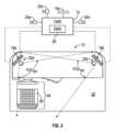
ディスプレイ18a、18b、18cは、運転席26に運転者が着席する運転室22内の運転者領域24に向いている。運転者領域24における運転者活動を評価して、注意散漫な運転者行動を識別するために運転者監視システム(DMS)29をCMS15に組み込むことが望ましい。DMS29の一例を図2に示す。第1及び第2の車内カメラ28a,28bは、第1及び第2のディスプレイ18a,18bの近くの車両運転室22内に配置され、車両運転室22内の運転者画像をキャプチャするように構成される。第1及び第2の車内カメラ28a,28bは、それぞれ、運転者領域24内で少なくとも部分的に互いに重なる第1及び第2の車内視野FOVIN1,FOVIN2を提供する。第1のディスプレイ18aは、第2の車内視野FOVIN2内に位置するように配置され、第2のディスプレイ18bは、第1の車内視野FOVIN1内に位置するように配置される。運転者活動は、第1及び第2の車内カメラ28a、28bを使用して車両を操作している間の運転者の視線及び/又は姿勢を監視することによって決定されてもよい。 The
次に図3を参照し、図2を引き続き参照すると、視線追跡カメラであり得る第1及び第2の車内カメラ28a、28bは、運転室22内の運転者の画像を記録するように構成される。そのような視線追跡システムの1つは、2020年4月10日に出願されたUSSN16/845,228に開示されており、その全体が参照により本明細書に組み込まれる。With reference now to FIG. 3 and continuing reference to FIG. 2, first and second in-
DMS29に関連するセンサ36-44、54-56は、例えば、記録された画像における運転者の視線方向を決定することにより、注意散漫な運転に対応する事前定義された基準に基づいて車両の異常運転事象を検出するように構成される。ECU又はコントローラ30は、第1及び第2の車内カメラ28a、28bと通信しており、記録された画像の中の特定の画像に示される運転者の視線方向が、事前定義された時間閾値を超える時間の間、事前定義された警告運転者領域の外にあることに基づいて、潜在的な注意散漫運転事象を検出するように構成される。コントローラ30は、コントローラエリアネットワーク(“CAN”)バスであり得る車両データバス52を介して、構成要素32、34、36、38、40、42、44、46、48、50、54、56に動作可能に接続される。コントローラ30は、潜在的な注意散漫運転事象に基づいて、以下の事前定義されたアクション、すなわち、フリートマネージャへの特定の画像の送信、及び異常運転画像のローカルリポジトリへの特定の画像の保存の1つ又は両方を実行するように構成される。コントローラ30は、必要に応じて、1つのコントローラ又は複数のコントローラであってもよい。The sensors 36-44, 54-56 associated with the
図4は、コントローラ30のより詳細な概略図である。コントローラ30は、メモリ62に動作可能に接続されるプロセッサ60と、通信インタフェース64とを含む。プロセッサ60は、マイクロプロセッサ、マイクロコントローラ、特定用途集積回路(ASIC)等の1つ以上の処理回路を含む。メモリ62は、読み出し専用メモリ(ROM)、ランダムアクセスメモリ、キャッシュメモリ、フラッシュメモリデバイス、光学記憶デバイス等の1つ又は複数のタイプのメモリを含んでもよい。メモリ62は、異常運転画像のローカルリポジトリ66を含み、任意選択的に、畳み込みニューラルネットワーク(“CNN”)67、運転者注意モデル68、及び/又は運転者注視モデル69も含んでもよい。いくつかの例では、姿勢検出器70もメモリ62内に含まれる。CNN67は、いくつかの例では、運転者が車両10の運転室内でモバイルデバイスを利用しているかどうかを検出するように動作可能である。本明細書で使用される「モバイルデバイス」とは、携帯電話、スマートフォン、タブレット、パーソナルメディアプレーヤ等のハンドヘルド電子デバイスを指す。コントローラ30の一部として図示されているが、CNN67は、その代わりに、フリート管理サーバ等、車両10の外部に記憶され得ることが理解される。通信インタフェース64は、コントローラ30と他の構成要素との間の通信を提供する(例えば、車両データバス52への有線接続)。他の例では、CNN67は、運転者の全体的な姿勢を検出し、その姿勢が注意を払った運転に対応するか注意を怠った運転に対応するかに基づいて、コントローラ30内の1つ以上の応答をトリガするように動作可能である。4 is a more detailed schematic diagram of the
いくつかの実施形態では、第1及び第2の車内カメラ28a、28bは、車両10の運転室内の運転者の画像を記録し、記録された画像における運転者の視線方向を決定するように構成される視線追跡カメラによって提供される。このようなカメラは、SmartEye(https://smarteye.se/)及びEyeSight(http://www.eyesight-tech.com/)から市販されている。一例では、第1及び第2の車内カメラ28a、28bは、赤外光又は近赤外光をユーザの眼に向け、次いで運転者の眼からのその赤外光の反射を測定することによって視線を検出する。反射角に基づいて視線方向を確認することができる。別の例では、第1及び第2の車内カメラ28a,28bは、運転者の頭部の一般的な形状及び/又は記録された画像における運転者の顔の対称性から視線ベクトルを決定することによって、運転者の視線方向を推測する。これらの技術の両方は、当業者には周知であるので、本明細書では詳細には論じない。一例では、第1及び第2の車内カメラ28a、28bは、運転者情報システム及び/又は計器クラスタ46に統合される。In some embodiments, the first and second
上記の第1及び第2の車内カメラ28a、28bは、運転者の身体の位置、例えば、前かがみ又は左右に傾く、又は運転者の四肢の位置に関連する運転姿勢を検出するためにも使用することができる。姿勢を決定することにより、運転者の活動及び運転者の注意がどこに集中しているかに関連する追加情報を提供することができる。The first and second in-
姿勢検出器70は、CNN67を利用して、腕の位置及び向き、手の位置及び向き、胴体のねじれ、手及び顔の相対的な向き及び/又は位置、ステアリング装置に対する腕及び手の位置、及び運転者が現在置かれている姿勢を定義するために組み合わされる任意の数の類似した姿勢メトリックを含む運転者の姿勢を追跡するように構成される。次に、決定された姿勢は、多数の訓練された姿勢と相関され、注意を払っているか又は注意を払っていないかのいずれかとして識別される。さらに別の例では、CNN67は、姿勢検出と第1及び第2の車内カメラ28a、28bの視線検出とを組み合わせて、注意を払っている姿勢と注意を払っていない姿勢とを区別する能力をさらに向上させることができる。The
一例では、コントローラ30は、姿勢検出器70を使用して運転者の姿勢を継続的に識別し、注意を払っていない運転に対応する姿勢が検出されたときに注意を払っていない運転者応答をトリガするように構成される。一例として、応答は、聴覚、視覚、触覚、又は運転者に提供されるその他の感覚警告を含んでもよい。別の例では、注意を払っていない運転者応答は、監督者によるレビュー及び/又はさらなる分析のために、車両内のカメラから生成された注意を払っていない姿勢の運転者の画像を記憶するコマンドであってもよい。In one example, the
一例では、本明細書に記載される物理的実装は、コントローラ30による車両オペレータの姿勢の追跡及び監視を容易にする。コントローラ30が異常運転事象を検出すると、コントローラ30は、複数のビデオフィードからの画像をレビューして、運転者の姿勢を決定する。代替的に、姿勢は、姿勢検出器70によって継続的に監視される。姿勢が決定されると、コントローラ30は、少なくとも部分的に姿勢に基づいて運転者が注意をそらされたかどうかを決定する。In one example, the physical implementation described herein facilitates tracking and monitoring of the vehicle operator's posture by the
図5は、運転者を監視する1つの具体例の方法100のフローチャートである。コントローラ30は、異常運転事象について1つ以上の車両センサ(例えば、センサ36-44、54-56)を監視する(ステップ102)。異常運転事象が検出されない場合(ステップ104の“No”)、コントローラ30は異常運転事象について監視を続ける。異常運転事象が検出された場合(ステップ104の“Yes”)、コントローラ30は異常事象中の運転者を描写する特定の画像を運転室カメラ34から取得する(ステップ106)。コントローラ30は、特定の画像をフリートマネージャに送信し、及び/又は異常運転画像のローカルリポジトリ66に画像を保存し、その後、異常運転事象について車両センサの監視を再開する(ステップ108)。Figure 5 is a flow chart of one
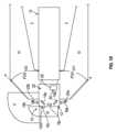
図7を参照すると、第1及び第2の車内カメラ28a、28bは、例えば、ディスプレイハウジング80に取り付けられた第1及び第2のディスプレイ18a、18b上にそれぞれ設けられている。ハウジング80は、調整可能な接続部88を有する取り付けブラケット86を介してAピラー82等の車両構造に固定される。調整可能な接続部88は、ボール及びソケット又は他の回転ジョイントであってもよく、運転者が所望の方向にディスプレイを向けることを可能にする。調整は、例えば、ディスプレイ画面からのグレアを軽減するために使用され得る。また、第1及び第2の車内カメラ28a、28bは、Aピラー82又はインストルメントパネル等に、第1及び第2のディスプレイ18a、18bとは別に取り付けられ得ることも理解されるべきである。第1及び第2の車内カメラ28a、28bは、第1及び第2のディスプレイ18a、18bの上又は近くに示されているが、車内カメラの一方又は両方は、他の場所、例えば、ディスプレイ18cの上又は近くに配置されてもよい。いずれにしても、第1及び第2の車内カメラ28a、28bの少なくとも一方は、それらの視野FOVIN1、FOVIN2が運転者領域24に対して調整可能であるように、相互に調整可能な動作位置を有する。 7, the first and second in-
車両組立時に、第1及び第2の車内カメラ28a、28bは、運転者活動を監視するために車両運転室12内の所望の領域を確実に包含するように、較正手順を行ってもよい。コントローラ30は、第1及び第2の車内カメラ28a、28bによる運転者領域24の正確で調整された画像のキャプチャ(例えば、運転者特徴の座標データ及び/又は画像ステッチング)に依存する。したがって、第1及び第2の車内カメラ28a、28bのいずれかが、この初期較正の後で攪乱されるか又は他のやり方で調整される場合、コントローラ30は、運転者活動をもはや正確に解釈することができない場合があるしたがって、第1及び第2の車内カメラ28a、28bがディスプレイ又は車内カメラを直接調整することによって移動される場合、それらは再較正されなければならない。車内カメラが再較正されるまで、運転者に(例えば、聴覚又は視覚の)警告が提供されてもよい。During vehicle assembly, the first and second
コントローラ、例えば、コントローラ30は、第1及び第2のディスプレイ18a、18b、並びに第1及び第2の車内カメラ28a、28bと通信している。コントローラ30は、相互に調整可能な動作位置を有する第1及び第2の車内カメラ28a、28bを使用して、車両運転者領域24における運転者活動を監視するように構成される。コントローラ30は、運転者活動を評価するために、第1及び第2の車内カメラ28a、28bの各々から運転者特徴(例えば、眼、頭部等)までの距離を決定するように構成される。運転者活動は、前述したように、運転者視線及び運転者姿勢の少なくとも1つを含む。本開示によれば、コントローラ30は、図6の200で示されるように、較正イベントに応答して較正手順を開始するように構成される。A controller, for example,
図6を参照すると、動作中、較正手順200は、第1及び第2の車内カメラ28a、28bの少なくとも1つが動作位置間で移動されることを含む較正イベント(ステップ202)を検出することを含む。較正イベントは、較正ウィンドウ内で、例えば、車両の始動手順中及び/又は車両が閾値車両速度未満である間に発生するように構成される。例えば、較正イベントは、第1及び第2の車内カメラ28a、28bの少なくとも1つが基準動作位置から逸脱すること、及び/又は第1及び第2のディスプレイ18a、18bの少なくとも1つが基準動作位置から逸脱することに対応する。例えば、ディスプレイは、運転者がグレアを最小限にするようにディスプレイを配置できるように調整可能であってもよい。ディスプレイに取り付けられた車内カメラの場合、ディスプレイを動かすとカメラが移動し、カメラの再較正が必要になる可能性がある。そのため、1つのカメラだけが移動した場合、おそらく1つのカメラだけが、そのカメラに可視のディスプレイを使用して再較正される。6, during operation, the
(図7の84における)パターンは、較正イベント検出202の後に、第1及び第2のディスプレイの少なくとも一方に表示される(ステップ204)。一例では、第1及び第2の車内カメラ28a、28bの各々と、第2及び第1のパターン84と間の距離をそれぞれ確立するために、パターン84が両方のディスプレイに提示される。一例では、第1及び第2のパターンの少なくとも1つは、より検出しやすい複数のライン(例えば、“T”、“X”等)を含む。パターン84は互いに同じであるように示されているが、パターンは異なっていてもよい。第1及び第2のパターンの少なくとも1つは、一例では、良好なコントラストを提供する白黒市松模様である。The pattern (at 84 in FIG. 7) is displayed on at least one of the first and second displays after calibration event detection 202 (step 204). In one example, the
パターン84は、運転室22の反対側に取り付けられる第1及び第2車内カメラ28a,28bの他方で検出される(ステップ206)。第1及び第2の車内カメラ28a,28bの他方は、第1及び第2の車内カメラ28a,28bの他方とパターン84との間の距離を確立するようにパターンによって較正される(ステップ208)。The
また、例示された実施形態では特定の構成要素の配置が開示されているが、他の配置も本開示から利益を得られることも理解するべきである。特定のステップシーケンスが示され、説明され、請求項に記載されているが、特に示されていない限り、ステップは任意の順序で実行されてもよく、分離又は結合されてもよく、それでも本発明の利益を得られることを理解するべきである。It should also be understood that while particular component arrangements are disclosed in the illustrated embodiments, other arrangements may benefit from the present disclosure. Although a particular sequence of steps is shown, described, and claimed, it should be understood that the steps may be performed in any order, separated, or combined, unless otherwise indicated, and still benefit from the present invention.
異なる例は、図に示された特定の構成要素を有するが、本発明の実施形態は、それらの特定の組み合わせに限定されない。ある例のいくつかの構成要素又は機能を、別の例の機能又は構成要素と組み合わせて使用することもできる。Although the different examples have specific components illustrated in the figures, embodiments of the invention are not limited to those specific combinations. Some components or features of one example may be used in combination with features or components of another example.
例示的な実施形態が開示されてきたが、当業者であれば、所定の修正が請求項の範囲内に入ることを認識するであろう。そのため、以下の請求項については、その真の範囲及び内容を判断するように検討されるべきである。Although exemplary embodiments have been disclosed, one of ordinary skill in the art would recognize that certain modifications would come within the scope of the claims. For that reason, the following claims should be studied to determine their true scope and content.
Claims (18)
Translated fromJapanese前記第1及び第2の車外カメラからの前記キャプチャ画像をそれぞれ描写するように構成される車両運転室内の第1及び第2のディスプレイと、
前記車両運転室内の運転者画像をキャプチャするように構成される第1及び第2の車内カメラであって、前記第1及び第2の車内カメラはそれぞれ、前記車両運転室内の車両運転者領域において互いに重なる第1及び第2の車内視野を有し、前記第1のディスプレイは前記第2の車内視野内にあり、前記第2のディスプレイは前記第1の車内視野内にある、第1及び第2の車内カメラと、
前記第1及び第2のディスプレイ及び前記第1及び第2の車内カメラと通信するコントローラであって、前記コントローラは、前記第1及び第2の車内カメラを使用して前記車両運転者領域における運転者活動を監視するように構成され、前記コントローラは、較正イベントに応答して較正手順を開始するように構成され、前記較正手順は、第1及び第2のディスプレイが第1及び第2のパターンをそれぞれ示すこと、及び前記第1及び第2の車内カメラがそれぞれ前記第2及び第1のパターンを検出して、前記第1及び第2の車内カメラのそれぞれと前記第2及び第1のパターンとの間の距離をそれぞれ確立するように、前記車両運転者領域に対して前記第1及び第2の車内カメラを較正することを含む、コントローラと
を備える、車両用のカメラミラーシステム。first and second exterior cameras configured to provide captured images of an exterior of the vehicle corresponding to firstand second views;
first and second displays in a vehicle cab configured to depict the captured images from the first and second exterior cameras, respectively;
first and second in-vehicle cameras configured to capture driver images within the vehicle cab, the first and second in-vehicle cameras having first and second in-vehicle fields of view that overlap one another in a vehicle driver area within the vehicle cab, the first display being within the second in-vehicle field of view and the second display being within the first in-vehicle field of view;
and a controller in communication with the first and second displays and the first and second interior cameras, the controller configured to monitor driver activity in the vehicle driver area using the first and second interior cameras, the controller configured to initiate a calibration procedure in response to a calibration event, the calibration procedure including calibrating the first and second interior cameras with respect to the vehicle driver area such that the first and second displays show first and second patterns, respectively, and the first and secondinterior cameras detect the second and first patterns, respectively, to establish distances between the first and second interior cameras and the second and first patterns, respectively.
前記較正ウィンドウは、車両始動手順の間であり、又は
前記較正ウィンドウは、閾値車両速度未満である、請求項1に記載のシステム。 The calibration event is configured to occur within a calibration window;
the calibration windowis during a vehicle start-up procedure; or
The system of claim1 , wherein the calibration window is less than a threshold vehicle speed.
前記方法は、第1及び第2のビューに対応する車両の外部の画像をキャプチャするように構成される第1及び第2の車外カメラと、それぞれ前記第1及び第2の車外カメラからキャプチャされた画像を描写するように構成される車両運転室内の第1及び第2のディスプレイとを有するカメラミラーシステムと共に使用されるように構成され、前記方法は、
動作位置間で移動可能な第1及び第2の車内カメラを提供するステップと、
前記第1及び第2の車内カメラの少なくとも1つが前記動作位置間で移動されることを含む較正イベントを検出するステップと、
前記較正イベントの検出後に前記第1及び第2のディスプレイの少なくとも1つにパターンを表示するステップと、
取り付けられた前記第1及び第2の車内カメラによりパターンを検出するステップと、
前記第1及び第2の車内カメラと前記パターンとの間の距離を確立するように、前記パターンによって前記第1及び第2の車内カメラの少なくとも1つを較正するステップと
を含む、方法。 1. A method of calibratingat least one offirst and second interior cameras used to observe a driver within a vehicle cab, comprising:
The method is configured for use with a camera mirror system having first and second exterior cameras configured to capture images of an exterior of the vehicle corresponding tofirst and second views, and first and second displays in a vehicle cab configured to depict images captured from the first and secondexterior cameras, respectively, the method comprising:
providingfirst and second in-vehicle cameras movable between operational positions;
detecting a calibration event includingat least one ofthe first and second interior cameras being moved between the operating positions;
displaying a pattern on at least one of the first and second displays after detecting the calibration event;
detecting a pattern withthe first and second in-vehicle cameras mounted thereon;
calibratingat least one ofthe first and second in-vehicle cameras with the pattern to establish a distance betweenthe first and second in-vehicle cameras and the pattern.
Applications Claiming Priority (3)
| Application Number | Priority Date | Filing Date | Title |
|---|---|---|---|
| US202063129927P | 2020-12-23 | 2020-12-23 | |
| US63/129,927 | 2020-12-23 | ||
| PCT/US2021/063869WO2022140162A1 (en) | 2020-12-23 | 2021-12-16 | Camera mirror system display camera calibration |
Publications (2)
| Publication Number | Publication Date |
|---|---|
| JP2024501253A JP2024501253A (en) | 2024-01-11 |
| JP7625701B2true JP7625701B2 (en) | 2025-02-03 |
Family
ID=79927225
Family Applications (1)
| Application Number | Title | Priority Date | Filing Date |
|---|---|---|---|
| JP2023538039AActiveJP7625701B2 (en) | 2020-12-23 | 2021-12-16 | Display camera calibration for camera mirror systems |
Country Status (5)
| Country | Link |
|---|---|
| US (1) | US11999299B2 (en) |
| EP (1) | EP4267434A1 (en) |
| JP (1) | JP7625701B2 (en) |
| CN (1) | CN116761745A (en) |
| WO (1) | WO2022140162A1 (en) |
Families Citing this family (6)
| Publication number | Priority date | Publication date | Assignee | Title |
|---|---|---|---|---|
| KR20230056838A (en)* | 2021-10-20 | 2023-04-28 | 주식회사 에스엘미러텍 | Digital Side Mirror System |
| US20250182330A1 (en)* | 2022-03-08 | 2025-06-05 | Mitsubishi Electric Corporation | Occupant monitoring device, occupant monitoring method, and medium |
| US20240075880A1 (en)* | 2022-09-01 | 2024-03-07 | Stoneridge Electronics Ab | Camera monitor system display brightness balancing |
| EP4584760A1 (en)* | 2022-09-09 | 2025-07-16 | Stoneridge, Inc. | Camera monitoring system including trailer presence detection using optical flow |
| US12277732B2 (en)* | 2022-12-28 | 2025-04-15 | Apollo Autonomous Driving USA LLC | Video camera calibration refinement for autonomous driving vehicles |
| CN115994954B (en)* | 2023-03-22 | 2023-06-27 | 浙江伽奈维医疗科技有限公司 | High-precision large-field near infrared optical camera calibration device and calibration method |
Citations (9)
| Publication number | Priority date | Publication date | Assignee | Title |
|---|---|---|---|---|
| JP2015232859A (en) | 2014-06-11 | 2015-12-24 | 株式会社デンソー | Safety confirmation support system and safety confirmation support method |
| JP2016074290A (en) | 2014-10-06 | 2016-05-12 | 株式会社デンソー | Vehicular monitoring system |
| US20170240185A1 (en) | 2016-02-23 | 2017-08-24 | Lg Electronics Inc. | Driver assistance apparatus and vehicle having the same |
| JP2017210063A (en) | 2016-05-24 | 2017-11-30 | 株式会社東海理化電機製作所 | Vehicle display device |
| JP6394281B2 (en) | 2014-10-29 | 2018-09-26 | 株式会社デンソー | In-vehicle alert system, alarm control device |
| WO2018181248A1 (en) | 2017-03-31 | 2018-10-04 | パナソニックIpマネジメント株式会社 | Imaging system and correction method |
| US20190206084A1 (en) | 2016-06-29 | 2019-07-04 | Seeing Machines Limited | Systems and methods for identifying pose of cameras in a scene |
| JP2019186853A (en) | 2018-04-16 | 2019-10-24 | 株式会社Jvcケンウッド | Vehicle display control device, vehicle display system, vehicle display control method, and program |
| US20200055480A1 (en) | 2018-08-17 | 2020-02-20 | Veoneer Us, Inc. | Vehicle cabin monitoring system |
Family Cites Families (7)
| Publication number | Priority date | Publication date | Assignee | Title |
|---|---|---|---|---|
| JP2009042162A (en)* | 2007-08-10 | 2009-02-26 | Toshiba Corp | Calibration apparatus and method |
| US20140070934A1 (en)* | 2012-09-07 | 2014-03-13 | GM Global Technology Operations LLC | Methods and systems for monitoring driver object detection |
| DE102016219031B4 (en) | 2016-09-30 | 2024-04-11 | Ford Global Technologies, Llc | Method and device for testing a driver assistance system |
| KR102631964B1 (en)* | 2016-11-23 | 2024-01-31 | 엘지이노텍 주식회사 | Method, Apparatus, System, Program and Recording Medium for Analyzing Image using Vehicle Driving Information |
| KR102630368B1 (en)* | 2018-10-25 | 2024-01-29 | 현대모비스 주식회사 | Apparatus for calibrating camera monitoring driver and method thereof |
| BR112021020043A2 (en)* | 2019-04-12 | 2021-12-14 | Stoneridge Electronics Ab | Monitoring mobile device usage for commercial vehicle fleet management |
| US11144754B2 (en)* | 2019-08-19 | 2021-10-12 | Nvidia Corporation | Gaze detection using one or more neural networks |
- 2021
- 2021-12-16USUS18/268,750patent/US11999299B2/enactiveActive
- 2021-12-16EPEP21847823.8Apatent/EP4267434A1/enactivePending
- 2021-12-16WOPCT/US2021/063869patent/WO2022140162A1/ennot_activeCeased
- 2021-12-16CNCN202180086580.9Apatent/CN116761745A/enactivePending
- 2021-12-16JPJP2023538039Apatent/JP7625701B2/enactiveActive
Patent Citations (9)
| Publication number | Priority date | Publication date | Assignee | Title |
|---|---|---|---|---|
| JP2015232859A (en) | 2014-06-11 | 2015-12-24 | 株式会社デンソー | Safety confirmation support system and safety confirmation support method |
| JP2016074290A (en) | 2014-10-06 | 2016-05-12 | 株式会社デンソー | Vehicular monitoring system |
| JP6394281B2 (en) | 2014-10-29 | 2018-09-26 | 株式会社デンソー | In-vehicle alert system, alarm control device |
| US20170240185A1 (en) | 2016-02-23 | 2017-08-24 | Lg Electronics Inc. | Driver assistance apparatus and vehicle having the same |
| JP2017210063A (en) | 2016-05-24 | 2017-11-30 | 株式会社東海理化電機製作所 | Vehicle display device |
| US20190206084A1 (en) | 2016-06-29 | 2019-07-04 | Seeing Machines Limited | Systems and methods for identifying pose of cameras in a scene |
| WO2018181248A1 (en) | 2017-03-31 | 2018-10-04 | パナソニックIpマネジメント株式会社 | Imaging system and correction method |
| JP2019186853A (en) | 2018-04-16 | 2019-10-24 | 株式会社Jvcケンウッド | Vehicle display control device, vehicle display system, vehicle display control method, and program |
| US20200055480A1 (en) | 2018-08-17 | 2020-02-20 | Veoneer Us, Inc. | Vehicle cabin monitoring system |
Also Published As
| Publication number | Publication date |
|---|---|
| JP2024501253A (en) | 2024-01-11 |
| CN116761745A (en) | 2023-09-15 |
| WO2022140162A1 (en) | 2022-06-30 |
| EP4267434A1 (en) | 2023-11-01 |
| US11999299B2 (en) | 2024-06-04 |
| US20240042936A1 (en) | 2024-02-08 |
Similar Documents
| Publication | Publication Date | Title |
|---|---|---|
| JP7625701B2 (en) | Display camera calibration for camera mirror systems | |
| DE102021203783B4 (en) | INTERNAL REARVIEW MIRROR ARRANGEMENT WITH DRIVER MONITORING SYSTEM | |
| US20160297362A1 (en) | Vehicle exterior side-camera systems and methods | |
| US20130096820A1 (en) | Virtual display system for a vehicle | |
| US20080117031A1 (en) | Security system for an automotive vehicle | |
| AU2019261701B2 (en) | Method, apparatus and system for determining line of sight, and wearable eye movement device | |
| JP2013203103A (en) | Display device for vehicle, control method therefor, and program | |
| US10836315B2 (en) | Mirror display system with blind spot display | |
| US20150124097A1 (en) | Optical reproduction and detection system in a vehicle | |
| US12026958B2 (en) | Vehicle camera mirror system with adjustable video feed | |
| US20140100770A1 (en) | Automotive Vehicle Having Surrounding Object Pattern Generator | |
| JPH0632175A (en) | Rearward image pick-up device for vehicle | |
| CN117002387A (en) | Display method and device of vehicle-mounted streaming media rearview mirror | |
| JP2018022958A (en) | Vehicle display controller and vehicle monitor system | |
| JP6365438B2 (en) | Driver state determination method and determination device therefor | |
| JP2019095892A (en) | Vehicle drive supporting device and vehicle drive supporting program | |
| JP6136891B2 (en) | Gaze detection device and gaze detection method | |
| CN219495252U (en) | Vehicle-mounted naked eye 3D projection navigation equipment and vehicle | |
| JP2024503031A (en) | Mobile device usage monitoring for commercial vehicle fleet management | |
| CN116572846A (en) | Display method, system and storage medium of vehicle-mounted electronic rearview mirror | |
| JP5566492B2 (en) | Rear view monitor system for vehicles | |
| JP6322991B2 (en) | Gaze detection device and gaze detection method | |
| Mohan et al. | Eye Gaze Estimation Invisible and IR Spectrum for Driver Monitoring System | |
| BR112023012433B1 (en) | VEHICLE MIRROR CAMERA SYSTEM AND INTERNAL CAMERA CALIBRATION METHOD | |
| CN113682232A (en) | Image display device |
Legal Events
| Date | Code | Title | Description |
|---|---|---|---|
| A621 | Written request for application examination | Free format text:JAPANESE INTERMEDIATE CODE: A621 Effective date:20230810 | |
| A131 | Notification of reasons for refusal | Free format text:JAPANESE INTERMEDIATE CODE: A131 Effective date:20240820 | |
| A521 | Request for written amendment filed | Free format text:JAPANESE INTERMEDIATE CODE: A523 Effective date:20241016 | |
| TRDD | Decision of grant or rejection written | ||
| A01 | Written decision to grant a patent or to grant a registration (utility model) | Free format text:JAPANESE INTERMEDIATE CODE: A01 Effective date:20250107 | |
| A61 | First payment of annual fees (during grant procedure) | Free format text:JAPANESE INTERMEDIATE CODE: A61 Effective date:20250122 | |
| R150 | Certificate of patent or registration of utility model | Ref document number:7625701 Country of ref document:JP Free format text:JAPANESE INTERMEDIATE CODE: R150 |