JP7624125B2 - Single endoscopic vessel harvesting device with visual cues to identify cutting element orientation - Patents.com - Google Patents
Single endoscopic vessel harvesting device with visual cues to identify cutting element orientation - Patents.comDownload PDFInfo
- Publication number
- JP7624125B2 JP7624125B2JP2021564652AJP2021564652AJP7624125B2JP 7624125 B2JP7624125 B2JP 7624125B2JP 2021564652 AJP2021564652 AJP 2021564652AJP 2021564652 AJP2021564652 AJP 2021564652AJP 7624125 B2JP7624125 B2JP 7624125B2
- Authority
- JP
- Japan
- Prior art keywords
- cutting
- cutting portion
- tip
- surgical device
- visual cue
- Prior art date
- Legal status (The legal status is an assumption and is not a legal conclusion. Google has not performed a legal analysis and makes no representation as to the accuracy of the status listed.)
- Active
Links
- 238000005520cutting processMethods0.000titleclaimsdescription361
- 230000000007visual effectEffects0.000titleclaimsdescription73
- 238000003306harvestingMethods0.000titledescription21
- 230000007704transitionEffects0.000claimsdescription30
- 210000004204blood vesselAnatomy0.000claimsdescription27
- 238000007373indentationMethods0.000claimsdescription3
- 238000013459approachMethods0.000claimsdescription2
- 238000000034methodMethods0.000description29
- 238000002224dissectionMethods0.000description24
- 210000001519tissueAnatomy0.000description19
- 239000000463materialSubstances0.000description13
- 238000007789sealingMethods0.000description12
- 238000001356surgical procedureMethods0.000description10
- 210000002808connective tissueAnatomy0.000description9
- 239000004033plasticSubstances0.000description9
- 229920003023plasticPolymers0.000description9
- 230000006870functionEffects0.000description8
- 239000002184metalSubstances0.000description7
- 229910052751metalInorganic materials0.000description7
- 230000008569processEffects0.000description7
- 230000009471actionEffects0.000description6
- 230000006378damageEffects0.000description5
- 208000014674injuryDiseases0.000description5
- 238000012986modificationMethods0.000description5
- 230000004048modificationEffects0.000description5
- 238000000576coating methodMethods0.000description4
- 230000006835compressionEffects0.000description4
- 238000007906compressionMethods0.000description4
- 238000010438heat treatmentMethods0.000description4
- 238000000926separation methodMethods0.000description4
- 230000008733traumaEffects0.000description4
- 230000002792vascularEffects0.000description4
- 238000012800visualizationMethods0.000description4
- 239000008280bloodSubstances0.000description3
- 210000004369bloodAnatomy0.000description3
- 230000017531blood circulationEffects0.000description3
- 239000011248coating agentSubstances0.000description3
- 238000002355open surgical procedureMethods0.000description3
- 230000003287optical effectEffects0.000description3
- 229920000139polyethylene terephthalatePolymers0.000description3
- 239000005020polyethylene terephthalateSubstances0.000description3
- 210000003752saphenous veinAnatomy0.000description3
- 238000013519translationMethods0.000description3
- LYCAIKOWRPUZTN-UHFFFAOYSA-NEthylene glycolChemical compoundOCCOLYCAIKOWRPUZTN-UHFFFAOYSA-N0.000description2
- 208000032843HemorrhageDiseases0.000description2
- 230000008901benefitEffects0.000description2
- 230000002457bidirectional effectEffects0.000description2
- 210000004556brainAnatomy0.000description2
- 238000012790confirmationMethods0.000description2
- 210000004351coronary vesselAnatomy0.000description2
- 239000012636effectorSubstances0.000description2
- 230000000694effectsEffects0.000description2
- 238000003384imaging methodMethods0.000description2
- 230000006872improvementEffects0.000description2
- 238000001746injection mouldingMethods0.000description2
- -1polyethylene terephthalatePolymers0.000description2
- 210000002321radial arteryAnatomy0.000description2
- 238000007920subcutaneous administrationMethods0.000description2
- 210000004003subcutaneous fatAnatomy0.000description2
- 241001631457CannulaSpecies0.000description1
- KRHYYFGTRYWZRS-UHFFFAOYSA-MFluoride anionChemical compound[F-]KRHYYFGTRYWZRS-UHFFFAOYSA-M0.000description1
- 208000024248Vascular System injuryDiseases0.000description1
- 208000012339Vascular injuryDiseases0.000description1
- 208000027418Wounds and injuryDiseases0.000description1
- 239000000853adhesiveSubstances0.000description1
- 230000001070adhesive effectEffects0.000description1
- 210000003423ankleAnatomy0.000description1
- 210000001367arteryAnatomy0.000description1
- 230000000712assemblyEffects0.000description1
- 238000000429assemblyMethods0.000description1
- QVGXLLKOCUKJST-UHFFFAOYSA-Natomic oxygenChemical compound[O]QVGXLLKOCUKJST-UHFFFAOYSA-N0.000description1
- 239000000560biocompatible materialSubstances0.000description1
- 208000034158bleedingDiseases0.000description1
- 230000000740bleeding effectEffects0.000description1
- 210000001124body fluidAnatomy0.000description1
- 239000010839body fluidSubstances0.000description1
- 238000004891communicationMethods0.000description1
- 239000002131composite materialSubstances0.000description1
- 238000010276constructionMethods0.000description1
- 230000008602contractionEffects0.000description1
- 238000013461designMethods0.000description1
- 238000010586diagramMethods0.000description1
- 238000006073displacement reactionMethods0.000description1
- 239000013536elastomeric materialSubstances0.000description1
- 238000010292electrical insulationMethods0.000description1
- 238000002674endoscopic surgeryMethods0.000description1
- 210000003414extremityAnatomy0.000description1
- 210000003195fasciaAnatomy0.000description1
- 239000012530fluidSubstances0.000description1
- 210000004013groinAnatomy0.000description1
- 238000009499grossingMethods0.000description1
- 239000005337ground glassSubstances0.000description1
- 230000023597hemostasisEffects0.000description1
- WGCNASOHLSPBMP-UHFFFAOYSA-NhydroxyacetaldehydeNatural productsOCC=OWGCNASOHLSPBMP-UHFFFAOYSA-N0.000description1
- 238000002513implantationMethods0.000description1
- 238000003780insertionMethods0.000description1
- 230000037431insertionEffects0.000description1
- 210000001349mammary arteryAnatomy0.000description1
- 230000007246mechanismEffects0.000description1
- 239000007769metal materialSubstances0.000description1
- 150000002739metalsChemical class0.000description1
- 210000003205muscleAnatomy0.000description1
- 239000000615nonconductorSubstances0.000description1
- 229910052760oxygenInorganic materials0.000description1
- 239000001301oxygenSubstances0.000description1
- 230000037361pathwayEffects0.000description1
- 229920000515polycarbonatePolymers0.000description1
- 239000004417polycarbonateSubstances0.000description1
- 229920005644polyethylene terephthalate glycol copolymerPolymers0.000description1
- 238000002360preparation methodMethods0.000description1
- 238000012545processingMethods0.000description1
- 230000004044responseEffects0.000description1
- 239000012781shape memory materialSubstances0.000description1
- 210000003491skinAnatomy0.000description1
- 239000007779soft materialSubstances0.000description1
- 239000007787solidSubstances0.000description1
- 230000000451tissue damageEffects0.000description1
- 231100000827tissue damageToxicity0.000description1
- 238000012546transferMethods0.000description1
- 230000001131transforming effectEffects0.000description1
- 239000012780transparent materialSubstances0.000description1
- 238000011144upstream manufacturingMethods0.000description1
- 238000003466weldingMethods0.000description1
Images


Classifications
- A—HUMAN NECESSITIES
- A61—MEDICAL OR VETERINARY SCIENCE; HYGIENE
- A61B—DIAGNOSIS; SURGERY; IDENTIFICATION
- A61B18/00—Surgical instruments, devices or methods for transferring non-mechanical forms of energy to or from the body
- A61B18/04—Surgical instruments, devices or methods for transferring non-mechanical forms of energy to or from the body by heating
- A61B18/12—Surgical instruments, devices or methods for transferring non-mechanical forms of energy to or from the body by heating by passing a current through the tissue to be heated, e.g. high-frequency current
- A61B18/14—Probes or electrodes therefor
- A61B18/148—Probes or electrodes therefor having a short, rigid shaft for accessing the inner body transcutaneously, e.g. for neurosurgery or arthroscopy
- A—HUMAN NECESSITIES
- A61—MEDICAL OR VETERINARY SCIENCE; HYGIENE
- A61B—DIAGNOSIS; SURGERY; IDENTIFICATION
- A61B17/00—Surgical instruments, devices or methods
- A61B17/00008—Vein tendon strippers
- A—HUMAN NECESSITIES
- A61—MEDICAL OR VETERINARY SCIENCE; HYGIENE
- A61B—DIAGNOSIS; SURGERY; IDENTIFICATION
- A61B17/00—Surgical instruments, devices or methods
- A61B17/32—Surgical cutting instruments
- A61B17/320016—Endoscopic cutting instruments, e.g. arthroscopes, resectoscopes
- A—HUMAN NECESSITIES
- A61—MEDICAL OR VETERINARY SCIENCE; HYGIENE
- A61B—DIAGNOSIS; SURGERY; IDENTIFICATION
- A61B17/00—Surgical instruments, devices or methods
- A61B17/32—Surgical cutting instruments
- A61B17/3201—Scissors
- A—HUMAN NECESSITIES
- A61—MEDICAL OR VETERINARY SCIENCE; HYGIENE
- A61B—DIAGNOSIS; SURGERY; IDENTIFICATION
- A61B17/00—Surgical instruments, devices or methods
- A61B17/00234—Surgical instruments, devices or methods for minimally invasive surgery
- A61B2017/00238—Type of minimally invasive operation
- A61B2017/00243—Type of minimally invasive operation cardiac
- A61B2017/00247—Making holes in the wall of the heart, e.g. laser Myocardial revascularization
- A61B2017/00252—Making holes in the wall of the heart, e.g. laser Myocardial revascularization for by-pass connections, i.e. connections from heart chamber to blood vessel or from blood vessel to blood vessel
- A—HUMAN NECESSITIES
- A61—MEDICAL OR VETERINARY SCIENCE; HYGIENE
- A61B—DIAGNOSIS; SURGERY; IDENTIFICATION
- A61B17/00—Surgical instruments, devices or methods
- A61B17/00234—Surgical instruments, devices or methods for minimally invasive surgery
- A61B2017/00292—Surgical instruments, devices or methods for minimally invasive surgery mounted on or guided by flexible, e.g. catheter-like, means
- A61B2017/00296—Surgical instruments, devices or methods for minimally invasive surgery mounted on or guided by flexible, e.g. catheter-like, means mounted on an endoscope
- A—HUMAN NECESSITIES
- A61—MEDICAL OR VETERINARY SCIENCE; HYGIENE
- A61B—DIAGNOSIS; SURGERY; IDENTIFICATION
- A61B17/00—Surgical instruments, devices or methods
- A61B2017/00743—Type of operation; Specification of treatment sites
- A61B2017/00778—Operations on blood vessels
- A—HUMAN NECESSITIES
- A61—MEDICAL OR VETERINARY SCIENCE; HYGIENE
- A61B—DIAGNOSIS; SURGERY; IDENTIFICATION
- A61B17/00—Surgical instruments, devices or methods
- A61B2017/00831—Material properties
- A61B2017/00902—Material properties transparent or translucent
- A61B2017/00907—Material properties transparent or translucent for light
- A—HUMAN NECESSITIES
- A61—MEDICAL OR VETERINARY SCIENCE; HYGIENE
- A61B—DIAGNOSIS; SURGERY; IDENTIFICATION
- A61B17/00—Surgical instruments, devices or methods
- A61B2017/00969—Surgical instruments, devices or methods used for transplantation
- A—HUMAN NECESSITIES
- A61—MEDICAL OR VETERINARY SCIENCE; HYGIENE
- A61B—DIAGNOSIS; SURGERY; IDENTIFICATION
- A61B17/00—Surgical instruments, devices or methods
- A61B17/34—Trocars; Puncturing needles
- A61B17/3417—Details of tips or shafts, e.g. grooves, expandable, bendable; Multiple coaxial sliding cannulas, e.g. for dilating
- A61B2017/3454—Details of tips
- A—HUMAN NECESSITIES
- A61—MEDICAL OR VETERINARY SCIENCE; HYGIENE
- A61B—DIAGNOSIS; SURGERY; IDENTIFICATION
- A61B18/00—Surgical instruments, devices or methods for transferring non-mechanical forms of energy to or from the body
- A61B2018/00053—Mechanical features of the instrument of device
- A61B2018/00297—Means for providing haptic feedback
- A61B2018/00309—Means for providing haptic feedback passive, e.g. palpable click when activating a button
- A—HUMAN NECESSITIES
- A61—MEDICAL OR VETERINARY SCIENCE; HYGIENE
- A61B—DIAGNOSIS; SURGERY; IDENTIFICATION
- A61B18/00—Surgical instruments, devices or methods for transferring non-mechanical forms of energy to or from the body
- A61B2018/00315—Surgical instruments, devices or methods for transferring non-mechanical forms of energy to or from the body for treatment of particular body parts
- A61B2018/00345—Vascular system
- A61B2018/00351—Heart
- A61B2018/00386—Coronary vessels
- A—HUMAN NECESSITIES
- A61—MEDICAL OR VETERINARY SCIENCE; HYGIENE
- A61B—DIAGNOSIS; SURGERY; IDENTIFICATION
- A61B18/00—Surgical instruments, devices or methods for transferring non-mechanical forms of energy to or from the body
- A61B2018/00571—Surgical instruments, devices or methods for transferring non-mechanical forms of energy to or from the body for achieving a particular surgical effect
- A61B2018/00601—Cutting
- A—HUMAN NECESSITIES
- A61—MEDICAL OR VETERINARY SCIENCE; HYGIENE
- A61B—DIAGNOSIS; SURGERY; IDENTIFICATION
- A61B18/00—Surgical instruments, devices or methods for transferring non-mechanical forms of energy to or from the body
- A61B2018/00571—Surgical instruments, devices or methods for transferring non-mechanical forms of energy to or from the body for achieving a particular surgical effect
- A61B2018/0063—Sealing
- A—HUMAN NECESSITIES
- A61—MEDICAL OR VETERINARY SCIENCE; HYGIENE
- A61B—DIAGNOSIS; SURGERY; IDENTIFICATION
- A61B18/00—Surgical instruments, devices or methods for transferring non-mechanical forms of energy to or from the body
- A61B2018/0091—Handpieces of the surgical instrument or device
- A61B2018/00916—Handpieces of the surgical instrument or device with means for switching or controlling the main function of the instrument or device
- A—HUMAN NECESSITIES
- A61—MEDICAL OR VETERINARY SCIENCE; HYGIENE
- A61B—DIAGNOSIS; SURGERY; IDENTIFICATION
- A61B18/00—Surgical instruments, devices or methods for transferring non-mechanical forms of energy to or from the body
- A61B2018/00982—Surgical instruments, devices or methods for transferring non-mechanical forms of energy to or from the body combined with or comprising means for visual or photographic inspections inside the body, e.g. endoscopes
- A—HUMAN NECESSITIES
- A61—MEDICAL OR VETERINARY SCIENCE; HYGIENE
- A61B—DIAGNOSIS; SURGERY; IDENTIFICATION
- A61B18/00—Surgical instruments, devices or methods for transferring non-mechanical forms of energy to or from the body
- A61B18/04—Surgical instruments, devices or methods for transferring non-mechanical forms of energy to or from the body by heating
- A61B18/12—Surgical instruments, devices or methods for transferring non-mechanical forms of energy to or from the body by heating by passing a current through the tissue to be heated, e.g. high-frequency current
- A61B18/14—Probes or electrodes therefor
- A61B2018/1405—Electrodes having a specific shape
- A61B2018/1412—Blade
- A61B2018/1415—Blade multiple blades
- A—HUMAN NECESSITIES
- A61—MEDICAL OR VETERINARY SCIENCE; HYGIENE
- A61B—DIAGNOSIS; SURGERY; IDENTIFICATION
- A61B18/00—Surgical instruments, devices or methods for transferring non-mechanical forms of energy to or from the body
- A61B18/04—Surgical instruments, devices or methods for transferring non-mechanical forms of energy to or from the body by heating
- A61B18/12—Surgical instruments, devices or methods for transferring non-mechanical forms of energy to or from the body by heating by passing a current through the tissue to be heated, e.g. high-frequency current
- A61B18/14—Probes or electrodes therefor
- A61B2018/1475—Electrodes retractable in or deployable from a housing
- A—HUMAN NECESSITIES
- A61—MEDICAL OR VETERINARY SCIENCE; HYGIENE
- A61B—DIAGNOSIS; SURGERY; IDENTIFICATION
- A61B90/00—Instruments, implements or accessories specially adapted for surgery or diagnosis and not covered by any of the groups A61B1/00 - A61B50/00, e.g. for luxation treatment or for protecting wound edges
- A61B90/08—Accessories or related features not otherwise provided for
- A61B2090/0807—Indication means
- A61B2090/0811—Indication means for the position of a particular part of an instrument with respect to the rest of the instrument, e.g. position of the anvil of a stapling instrument
- A—HUMAN NECESSITIES
- A61—MEDICAL OR VETERINARY SCIENCE; HYGIENE
- A61B—DIAGNOSIS; SURGERY; IDENTIFICATION
- A61B90/00—Instruments, implements or accessories specially adapted for surgery or diagnosis and not covered by any of the groups A61B1/00 - A61B50/00, e.g. for luxation treatment or for protecting wound edges
- A61B90/39—Markers, e.g. radio-opaque or breast lesions markers
- A61B2090/3937—Visible markers
- A—HUMAN NECESSITIES
- A61—MEDICAL OR VETERINARY SCIENCE; HYGIENE
- A61B—DIAGNOSIS; SURGERY; IDENTIFICATION
- A61B90/00—Instruments, implements or accessories specially adapted for surgery or diagnosis and not covered by any of the groups A61B1/00 - A61B50/00, e.g. for luxation treatment or for protecting wound edges
- A61B90/36—Image-producing devices or illumination devices not otherwise provided for
- A61B90/361—Image-producing devices, e.g. surgical cameras
Landscapes
- Health & Medical Sciences (AREA)
- Life Sciences & Earth Sciences (AREA)
- Surgery (AREA)
- Engineering & Computer Science (AREA)
- Animal Behavior & Ethology (AREA)
- Veterinary Medicine (AREA)
- Biomedical Technology (AREA)
- Heart & Thoracic Surgery (AREA)
- Medical Informatics (AREA)
- Molecular Biology (AREA)
- Nuclear Medicine, Radiotherapy & Molecular Imaging (AREA)
- General Health & Medical Sciences (AREA)
- Public Health (AREA)
- Physics & Mathematics (AREA)
- Plasma & Fusion (AREA)
- Otolaryngology (AREA)
- Pathology (AREA)
- Orthopedic Medicine & Surgery (AREA)
- Rheumatology (AREA)
- Neurology (AREA)
- Neurosurgery (AREA)
- Surgical Instruments (AREA)
Description
Translated fromJapanese 関連出願の相互参照
本出願は、両方の出願に共通な全ての主題のために、2019年5月1日に出願された共係属する米国仮特許出願第62/841,413号に対する優先権とその利益を主張する。当該仮特許出願の開示は、本明細書に全て援用する。 CROSS-REFERENCE TO RELATED APPLICATIONS This application claims priority to and the benefit of co-pending U.S. Provisional Patent Application No. 62/841,413, filed May 1, 2019, for all subject matter common to both applications, the disclosure of which is incorporated herein by reference in its entirety.
本開示の実施形態は、内視鏡カニューレ及びその使用方法に関する。特に、本発明は、切断要素の配向を識別するために視覚的な手がかりを備える単一の内視鏡血管採取装置に関する。Embodiments of the present disclosure relate to endoscopic cannulas and methods of use thereof. In particular, the present invention relates to a single endoscopic vessel harvesting device with visual cues to identify the orientation of the cutting element.
血管採取は、冠状動脈バイパス手術と組み合わせて一般に用いられる手術技術である。バイパス手術の間、血液は、遮断された動脈を迂回してルートを変更され、心臓への血液の流れ及び酸素を回復及び改善する。血液は、バイパスグラフトを用いてルートを変更され、バイパスグラフトの一端は、遮断された領域の上流の血液源に取り付けられ、他端は、遮断された領域の下流に取り付けられ、遮断された領域を迂回する「導管」チャネルまたは新しい血流接続を作り出す。一般に、手術は、体の別の部分から健康な血管を取り外すまたは「採取し」、バイパスグラフトを作り出す。冠状動脈バイパスグラフト手術の成功は、導管の品質及びどのように導管が移植する前に血管採取及び準備ステップの間、取り扱われるまたは処理されるかによって影響される。Vessel harvesting is a surgical technique commonly used in conjunction with coronary artery bypass surgery. During bypass surgery, blood is rerouted around a blocked artery to restore and improve blood flow and oxygen to the heart. Blood is rerouted using a bypass graft, one end of which is attached to a blood source upstream of the blocked area and the other end is attached downstream of the blocked area, creating a "conduit" channel or new blood flow connection that bypasses the blocked area. Generally, the surgery removes or "harvested" a healthy blood vessel from another part of the body and creates the bypass graft. The success of coronary artery bypass graft surgery is influenced by the quality of the conduit and how the conduit is handled or processed during the vessel harvesting and preparation steps before implantation.
血管採取方法は、封鎖するバイパス導管として用いられる、従来脚の大伏在静脈または腕の橈骨動脈などの血管を選択するステップと、主血管導管から分岐する小さい血管を切断するステップと、体から主導管を採取するステップと、を含む。この慣行は、残した血管ネットワークに害を及ぼさず、治癒し、四肢に十分な血流を維持し、患者は、目立った影響なしに正常な機能に戻ることができる。The vessel harvesting method involves selecting a vessel, traditionally the great saphenous vein in the leg or the radial artery in the arm, to be used as a bypass conduit to be blocked, severing smaller vessels that branch off from the main vessel conduit, and harvesting the main vessel from the body. This practice leaves the remaining vascular network unharmed, allowing it to heal and maintain adequate blood flow to the limb, and allowing the patient to return to normal function without noticeable repercussions.
血管採取のための非侵襲技術は、小さい切開のみ必要とする手術である、内視鏡血管採取として知られる。内視鏡血管採取手術は、鼠径部から足首まで単一の長い切開を必要とした従来の「開放」手術を改善したものであるが、内視鏡手術は、まだ扱いにくく難しい。特に、現在の内視鏡採取システムは、複数の道具を必要とし、バイパス導管への損傷の可能性を増加するだけでなく、手術期間を延ばす。したがって、内視鏡血管採取のシステム及び方法の改善は、まだ要求される。A non-invasive technique for vessel harvesting is known as endoscopic vessel harvesting, a procedure that requires only a small incision. Although endoscopic vessel harvesting is an improvement over traditional "open" surgery that required a single long incision from the groin to the ankle, endoscopic surgery is still cumbersome and difficult. In particular, current endoscopic harvesting systems require multiple tools, which not only increases the chance of damage to the bypass conduit, but also extends the duration of the surgery. Thus, improvements in endoscopic vessel harvesting systems and methods are still required.
単一の内視鏡血管採取装置が開示される。いくつかの実施形態において、そのような装置は、近位端と遠位端を有する細長い本体と、少なくとも1つの切断部の場所を指定する視覚的な手がかりを備える先端であって、先端は、細長い本体の遠位端に配置される先端と、第1の切断部(すなわち切断刃または切断部材)及び第2の切断部を有する切断ユニットであって、第1の切断部と第2の切断部は、細長い本体に対して長手方向に移動可能であり、第1の切断部と第2の切断部の間の血管を捕らえ、先端の周りで円周方向に互いに対して回転可能であり、捕らえられた血管を切断する、切断ユニットと、最後に切断ユニットと係合し、他の切断部に向かって少なくとも1つの切断部を付勢する付勢部材と、を備える。A single endoscopic vessel harvesting device is disclosed. In some embodiments, such a device comprises an elongated body having a proximal end and a distal end, a tip with a visual cue designating the location of at least one cutting portion, the tip being disposed at the distal end of the elongated body, a cutting unit having a first cutting portion (i.e., a cutting blade or cutting member) and a second cutting portion, the first cutting portion and the second cutting portion being longitudinally movable relative to the elongated body to capture a vessel between the first cutting portion and the second cutting portion and rotatable relative to each other circumferentially about the tip to sever the captured vessel, and finally a biasing member engaging the cutting unit and biasing at least one cutting portion toward the other cutting portion.
本発明の例示の実施形態に従って、手術装置が提供される。手術装置は、本体の遠位端の先端に終端する細長い本体と、遠位端に向かって細長い本体に対して長手方向に移動可能な第1の切断部と第2の切断部を有する切断ユニットであって、少なくとも1つの切断部は、先端の周りで円周方向に他の切断部に対して回転可能である、切断ユニットと、を含む。装置は、また切断部が細長い本体の遠位端の先端を超えて長手方向に動かされるとき、少なくとも1つの切断部の場所を指定するために先端の視覚的な手がかりを含む。In accordance with an exemplary embodiment of the present invention, a surgical device is provided. The surgical device includes an elongated body terminating at a tip at the distal end of the body, and a cutting unit having a first cutting portion and a second cutting portion movable longitudinally relative to the elongated body toward the distal end, at least one cutting portion being rotatable relative to the other cutting portion in a circumferential direction about the tip. The device also includes a visual cue at the tip to designate the location of the at least one cutting portion when the cutting portion is moved longitudinally beyond the tip at the distal end of the elongated body.
本発明の態様に従って、第1の切断部と第2の切断部は、収縮位置から先端を超える伸長位置へ長手方向に動く。視覚的な手がかりは、刻み目、突起、及びマークの少なくとも1つである。視覚的な手がかりは、縦線、横線、矢印、点、及び点線の少なくとも1つである。第1の切断部は、刃として回転可能であり、第2の切断部は、アンビルとして静止している。視覚的な手がかりは、アンビルが細長い本体から長手方向に延在する場所を示す。視覚的な手がかりは、手術者の視野内にあり、電子ディスプレイで視覚化できる。視覚的な手がかりは、先端の内面または先端の外面の1つに配置される。In accordance with an aspect of the present invention, the first cutting portion and the second cutting portion move longitudinally from a retracted position to an extended position beyond the tip. The visual cue is at least one of an indentation, a protrusion, and a mark. The visual cue is at least one of a vertical line, a horizontal line, an arrow, a dot, and a dashed line. The first cutting portion is rotatable as a blade and the second cutting portion is stationary as an anvil. The visual cue indicates where the anvil extends longitudinally from the elongated body. The visual cue is within the field of view of the operator and is visualized on an electronic display. The visual cue is located on one of an inner surface of the tip or an outer surface of the tip.
本発明の態様に従って、手術装置は、さらに切断部が互いに離れる開放位置から切断部が互いに接触する閉鎖位置に切断部を動かすように構成された付勢部材を含む。手術装置は、さらに閉鎖位置から開放位置に切断部を動かすために細長い本体の近位端に配置された回転制御カラーを含み、付勢部材は、回転制御カラーに連結して切断部を閉鎖位置に戻す。第1の切断部と第2の切断は、第1の切断部と第2の切断との間に捕らえられた血管を、封止する、切断する、またはその両方を行うためにエネルギを与えられるように構成される。第1の切断部は、鋭い端部を有し、第1の切断部の鋭い端部に面する第2の切断部の端部は、平坦である。第1の切断部は、静止し、第2の切断部は、第1の切断部から離れて先端の周りで回転可能である。第2の切断部は、先端の周りを双方向に回転可能である。先端は、切断部が切欠きを通って延在することができるように、切欠きを有する剛性のある遷移要素を含む。In accordance with an aspect of the present invention, the surgical device further includes a biasing member configured to move the cutting portions from an open position where the cutting portions are separated from one another to a closed position where the cutting portions contact one another. The surgical device further includes a rotation control collar disposed at a proximal end of the elongated body to move the cutting portions from the closed position to the open position, and the biasing member couples to the rotation control collar to return the cutting portions to the closed position. The first cutting portion and the second cutting portion are configured to be energized to seal, cut, or both, a blood vessel captured between the first cutting portion and the second cutting portion. The first cutting portion has a sharp end, and an end of the second cutting portion facing the sharp end of the first cutting portion is flat. The first cutting portion is stationary and the second cutting portion is rotatable about the tip away from the first cutting portion. The second cutting portion is rotatable bidirectionally about the tip. The tip includes a rigid transition element having a notch such that the cutting portion can extend through the notch.
本発明の例示の実施形態に従って、血管採取方法が提供される。本発明の方法は、遠位端において切開先端を有する細長い本体を主血管に沿って進め、周囲の組織から主血管とその支血管を分離するステップと、切開先端の位置決めの視覚的な確認のために切開先端に視覚的な手がかりを向けるステップと、を含む。本発明の方法は、また基準点として視覚的な手がかりを用いながら遠位端に向けて第1の切断部と第2の切断部を動かし、第1と第2の切断部の間に血管を捕らえるステップと、を含む。In accordance with an exemplary embodiment of the present invention, a method of blood vessel harvesting is provided. The method of the present invention includes the steps of advancing an elongate body having a cutting tip at a distal end along a main blood vessel to separate the main blood vessel and its branch vessels from surrounding tissue, and directing a visual cue at the cutting tip for visual confirmation of the positioning of the cutting tip. The method of the present invention also includes moving a first cutting portion and a second cutting portion toward the distal end while using the visual cue as a reference point to capture the blood vessel between the first and second cutting portions.
本発明の態様に従って、本発明の方法は、さらに互いに対して遠位方向に第1の切断部と第2の切断部を動かすステップを含む。動かすステップにおいて、第1及び第2の切断部は、互いに接触する閉鎖位置にあり、互いに向けて付勢される。本発明の方法は、さらに第1の切断部によって支持された第1のRF電極と第2の切断部によって支持された第2のRF電極で血管を封止するステップを含む。本発明の方法は、さらに第1の切断部と第2の切断部の間の血管を捕らえるステップと、第1の切断部と第2の切断部の少なくとも1つを回転するステップと、を含む。回転するステップにおいて、第1の切断部は、静止し、第2の切断部は、先端の周りを双方向回転可能である。回転するステップにおいて、第1の切断部は、鋭い端部を有し、第1の切断部の鋭い端部に面する第2の切断部の端部は、平坦である。In accordance with an aspect of the present invention, the method further includes moving the first cutting portion and the second cutting portion in a distal direction relative to each other. In the moving step, the first and second cutting portions are in a closed position in contact with each other and are biased toward each other. The method further includes sealing the blood vessel with a first RF electrode supported by the first cutting portion and a second RF electrode supported by the second cutting portion. The method further includes capturing the blood vessel between the first cutting portion and the second cutting portion and rotating at least one of the first cutting portion and the second cutting portion. In the rotating step, the first cutting portion is stationary and the second cutting portion is bidirectionally rotatable about the tip. In the rotating step, the first cutting portion has a sharp end and the end of the second cutting portion facing the sharp end of the first cutting portion is flat.
さらなる特徴及び利点は、添付された図面と関連して理解されたとき、次の詳細な説明からさらに容易に明白になるであろう。Additional features and advantages will become more readily apparent from the following detailed description when taken in conjunction with the accompanying drawings.
本開示の実施形態は、さらに類似の構造がいくつかの図を通して類似の符号によって参照される、添付された図面を参照して説明される。示された図は、必ずしも縮尺通りではなく、代わりに本開示の実施形態の原理を説明することに一般に重点がおかれている。Embodiments of the present disclosure will be further described with reference to the accompanying drawings, in which like structures are referenced by like numerals throughout the several views. The figures shown are not necessarily to scale, with the emphasis instead generally being placed on illustrating the principles of embodiments of the present disclosure.
上記図面は、本開示の実施形態を記載する一方で、他の実施形態は、また説明で述べられるように、予期される。本開示は、提示する目的で及び限定でなく例示的な実施形態を示す。多くの他の改良及び実施形態は、当業者によって考案され、本開示の実施形態の原理の範囲及び精神内に含まれる。While the above drawings set forth embodiments of the present disclosure, other embodiments are contemplated, as also set forth in the description. This disclosure shows exemplary embodiments for purposes of presentation and not limitation. Many other modifications and embodiments can be devised by those skilled in the art and are within the scope and spirit of the principles of the embodiments of the present disclosure.
次の記載は、例示的な実施形態を提供するのみであり、開示の範囲、適用可能性、または構成を制限する意図はない。むしろ例示的な実施形態の次の説明は、当業者に1またはそれ以上の例示的な実施形態を実行するのに有効な説明を提供する。様々な変更が添付された特許請求の範囲に記載されるように本発明の精神及び範囲から逸脱することなく、要素の機能及び配置でなされることが理解される。The following description provides only exemplary embodiments and is not intended to limit the scope, applicability, or configuration of the disclosure. Rather, the following description of exemplary embodiments will provide one of ordinary skill in the art with an effective description for implementing one or more exemplary embodiments. It will be understood that various changes can be made in the function and arrangement of elements without departing from the spirit and scope of the invention as set forth in the appended claims.
特定の詳細が次の説明に与えられ、実施形態の完全な理解を提供する。しかしながら、実施形態がこれらの特定の詳細なく実施されることが当業者によって理解されるであろう。例えば、本発明のシステム、プロセス、及び他の要素は、不必要な詳細で実施形態を不明瞭にしないために、ブロック図形態の構成要素として示される。他の場合において、よく知られたプロセス、構造及び技術は、実施形態を不明瞭にすることを避けるために不必要な詳細なく示される。さらに、様々な図の同様な符号及び指定は、同様な要素を示した。Specific details are given in the following description to provide a thorough understanding of the embodiments. However, it will be understood by those skilled in the art that the embodiments may be practiced without these specific details. For example, systems, processes, and other elements of the present invention may be shown as components in block diagram form in order to avoid obscuring the embodiments in unnecessary detail. In other instances, well-known processes, structures, and techniques are shown without unnecessary detail in order to avoid obscuring the embodiments. Additionally, like numerals and designations in the various figures indicate like elements.
本開示は、内視鏡血管採取のための単一の装置を提供する。内視鏡血管採取のための現在のシステムは、複数の構成要素を含む。通常、内視鏡切開装置は、周囲の結合組織から主血管を切断することによって、周囲の結合組織から主血管を分離するために用いられる。その後、内視鏡カニューレは、さらに別の装置、内視鏡支流封止器具を導入するために用いられ、側枝を封止し、切断する。側枝が封止されるとすぐに、さらに別の装置がバイパスグラフトとして用いられる主血管の部分を採取するために用いられる。本開示の単一の装置は、切開機能、支流封止及び切断機能、及び任意に主血管封止及び切断機能を組み合わせ、血管操作を減らし、手術の容易さの改善をもたらす。本開示の装置は、また患者から封止され及び切断された主血管を摘出するために用いられる。The present disclosure provides a single device for endoscopic vessel harvesting. Current systems for endoscopic vessel harvesting include multiple components. Typically, an endoscopic dissection device is used to separate the main vessel from the surrounding connective tissue by severing the main vessel from the surrounding connective tissue. The endoscopic cannula is then used to introduce yet another device, an endoscopic tributary sealing instrument, to seal and sever the side branch. Once the side branch is sealed, yet another device is used to harvest a portion of the main vessel to be used as a bypass graft. The single device of the present disclosure combines dissection function, tributary sealing and cutting function, and optionally main vessel sealing and cutting function, resulting in reduced vessel manipulation and improved ease of surgery. The device of the present disclosure is also used to remove the sealed and severed main vessel from the patient.
血管操作を減らすことは、グラフトの損傷の可能性を減らす。採取器具の複数の通路との繰り返しの血管接触は、潜在的な血管損傷を増やす。例えば本開示の装置など単一の装置は、装置が進んだとき、周囲の組織から切断、すなわち主血管を分離し、及び支流と主血管を焼灼し、横に切断する及び血管は、複数の装置の挿入及び引き戻しよりむしろ装置の単一の通路で採取される。減少した直径を備えるそのような装置は、切開及び支流結紮のために用いられ、グラフト外傷は減る。本装置の比較的小さい直径は、また例えば内乳動脈などさらに曲がりくねった血管の採取を容易にする。Reducing vascular manipulation reduces the likelihood of graft injury. Repeated vascular contact with multiple passages of the harvesting instrument increases potential vascular injury. A single device, such as the device of the present disclosure, cuts, i.e., separates the main vessel from the surrounding tissue as the device advances, and cauterizes and transects the tributaries and main vessel, and the vessel is harvested with a single passage of the device rather than multiple device insertions and withdrawals. Such a device with a reduced diameter is used for dissection and tributary ligation, and graft trauma is reduced. The relatively small diameter of the device also facilitates harvesting of more tortuous vessels, such as the internal mammary artery.
図1Aを参照すると、本開示の内視鏡カニューレ100は、近位端104と遠位端106を有する細長い本体102を含み、切開先端120で終端する。カニューレ100は、さらに血管を封止し、切断するための遠位端106の周りに配置された切断ユニット150と切断ユニット150を制御するための制御ハンドル160を含む。切断ユニット150は、切断ユニット150の動作の間弾性力を提供する弾性装置を含む。弾性装置は、内視鏡カニューレ100の内部または外部である。With reference to FIG. 1A, the
いくつかの実施形態において、細長い本体102は、入口切開を通って血管採取部位に血管外を通るように構成される。細長い本体102を採取部位に進むことを助けるために、細長い本体102は、その長さに沿って軸方向に十分に剛性を有する。そのような特性を細長い本体102に提供するために、実施形態において、細長い本体102は、例えば、プラスチック材料、エラストマ材料、金属材料、形状記憶材料、複合材料または所望の特性を有するその他の材料など、生体適合性材料から作られる。所望の範囲に、細長い本体102は、幾分の柔軟性を備え、用途に依存して左右に径方向または横方向に動く。In some embodiments, the
いくつかの実施形態において、カニューレ100の細長い本体102は、中実である。他の実施形態において、内視鏡カニューレ100は、内腔を通って器具または材料を進める収容する1またはそれ以上の内腔を含む。いくつかの実施形態において、内視鏡カニューレ100は、内視鏡116がカニューレ100を用いて実行される手術を視覚化するために進められる内視鏡内腔103を含む。内視鏡カニューレ100は、内視鏡116を内視鏡カニューレ100に進めるための近位端104においてアダプタ114を含む。カニューレ100の追加の内腔は以下に説明される。In some embodiments, the
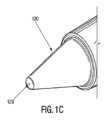
いくつかの実施形態において、内視鏡カニューレまたはカニューレ100は、内視鏡カニューレ100の遠位端106においてまたは周りに配置された切開先端120を含む。内視鏡の観察チップは、切開先端120の内側に配置される。いくつかの実施形態において、切開先端120は、内視鏡内腔103と流体連通する内部空洞を含み、内視鏡116が切開先端120に進められることができる。いくつかの実施形態において、チップオンチップタイプの内視鏡は、切開先端120の内側に一体化される。切開先端120は、また先端120を通って内視鏡観察ができるように透明である一方で、手術は、カニューレ100を用いて実行される。いくつかの実施形態において、切開先端120は、そこを通って内視鏡観察を容易にし、組織切断、すなわち分離の間、必要な制御ができる限り任意の形状を備える。いくつかの実施形態において、切開先端は、一般に円錐形である。In some embodiments, the endoscopic cannula or
いくつかの実施形態において、切開先端120は、おおよそ平坦な肩部122と、内視鏡カニューレ100が血管セグメントに沿って進むとき、近くの血管または組織を引き裂くまたは穴を開けることを最小にするまたは防ぎながら、周囲の組織から採取される血管セグメントの外傷のない分離のための鈍い端部126で終端する先細りした部分124を含む。鈍いように描かれるが、もちろん所望の範囲に切開先端120の端部126は、比較的鋭く作られ、カニューレ100の進行を強化することが理解されるべきである。さらに、おおよそ平坦な肩部122と先細りした部分124は、カニューレ100の操作性を強化するように、構造的に異なって構成される。例えば、おおよそ平坦な肩部122と先細りした部分124は、切断ユニット150の操作と性能を助ける1またはそれ以上の他の要素を含むように構成される。In some embodiments, the cutting
図1B及び図1Cの参照において、いくつかの実施形態において、切開先端120は、錐体形状であり、光源(図示せず)及びカメラシステム(図示せず)を備えるカニューレ100に挿入される内視鏡を通って観察するとき、内視鏡視野の中心において視覚的なゆがみまたは目がくらむ負の効果を最小にするような方法で遠位端129において形作られる。切開先端120の内面121は、先細りされ、切開先端120の遠位端126に向かって比較的一定の傾斜を備え、内部頂点123で終端し、図1Cに示されるように鋭い点である。切開先端120の外面125は、また切開先端120の遠位端126に向かって一定の傾斜で先細りされるが、遠位端126において、比較的丸い鈍い端部が切開の間、組織損傷を最小にするために形成される。1B and 1C, in some embodiments, the cutting
描かれるように、遠位端106において、切開先端120の外面125は、近位方向にそれ自体折り畳まれ、その後外部頂点127において終端し、鈍い外面を維持し、切開先端120の遠位端にくぼみを形成する。内部頂点123及び外部頂点127の両方は、カニューレ100、及びしたがっていくつかの実施形態において内視鏡116の中心の長手方向の軸と同一線上にある。言い換えると、内部頂点123と外部頂点127の中心は、カニューレ100の中心の長手方向の軸に配置される。内視鏡116の軸と同一線上でもある切開先端120の内面121と外面125のそれぞれの頂点を提供することによって、(内視鏡の軸に平行な)光路に垂直なそれらの面は、排除され、その後垂直な面からカメラに戻る光屈折を排除し、その後、光源及びカメラシステムを備える内視鏡116を通って観察するとき、視覚的なゆがみまたは目がくらむことを最小にするまたは排除する。As depicted, at the
さらに図1B及び図1Cを参照すると、切開プロセスの間、外傷の可能性を減らすために、いくつかの実施形態において、切開先端120は、切開先端が切開先端120に適用される力の作用下でわずかに偏向するように容易に曲げやすく、柔軟、または変形可能である。いくつかの実施形態において、切開先端120は、切開先端120の壁が先端表面に垂直な力の作用下で変形するように容易に圧縮できる。その目的で、切開先端120は、薄い壁プラスチック材料から形成され、切開先端は、負荷下で曲げることができる。適切な材料は、これに限定されるものではないが、ポリカーボネート、ポリエチレンテレフタレートグリコール変性(PETG)、ポリエチレンテレフタレート(PET)及び十分な光学的透明性を提供しつつ切開先端を負荷下で曲げることができる他の材料を含む。同時に、切開先端120は、軸または長手方向に十分な柱強度を備え、周囲の結合組織から血管の切開ができる。切開先端120の他の特性は、例えば(1)軸強度が長手方向の強度より大きい軸方向対長手方向(2)長手方向の強度が軸強度より大きい長手方向対軸方向(3)軸強度が長手方向の強度と近い軸方向対長手方向の可変の強度を有することが期待される。また、切開先端120は、2またはそれ以上の材料を含み、少なくとも1つの材料は、例えば、弾性、硬度、引張強度など異なる材料特性を有する。1B and 1C, in order to reduce the possibility of trauma during the dissection process, in some embodiments, the
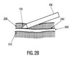
図2A-2Cの参照において、(例えば大きな伏在静脈または橈骨動脈など)バイパスグラフトで用いられる血管は、皮膚の表面の下の皮下空間にある。血管200は、図2Aに示されるように、主幹210と、血管幹210から出てくる枝血管220からなる。血管200及びその枝210は、皮下脂肪結合組織230に包み込まれ、主血管200が採取される前に、周囲の脂肪結合組織230がないように切断されることを必要とする。皮下脂肪230は、皮膚、筋肉、筋膜または他の結合組織より柔らかい。血管200に接着するが、脂肪結合組織230は、きれいに切断される血管200と境界240を形成する、すなわち、血管200の外層(外膜)と周囲の皮下脂肪230の間に自然切開面がある。2A-2C, the blood vessels used in the bypass graft (such as the great saphenous vein or radial artery) lie in the subcutaneous space below the surface of the skin. The
図2Bは、自然切開面に沿って切開先端120を備える血管200の主幹210の切開を描き、切開先端120は、血管200の外膜面に沿って進められる。通常、この面に沿った周囲の脂肪結合組織230から血管200の分離は、高い切開力を必要としない。いくつかの実施形態において、切開先端120は、十分な柱強度を備え、血管と周囲の組織の間の自然切開面に沿って周囲の組織230から血管200を切断する。2B depicts the dissection of the
他方で、図2Cに描かれるように、切開先端120が枝血管220に接近するとき、切開先端120は、枝血管220と主血管200の間の接合250において枝血管220を捕らえる。切開先端220による過剰な力の適用は、枝血管220を引き裂き、幹血管210から枝血管を切断する、またはさもなければ主血管200に損傷を引き起こす。この目的のために、いくつかの実施形態において、切開先端120は、十分な柱強度を備え、血管と周囲の組織の間の自然切開面に沿って周囲の組織230から血管200を切断する一方で、増加した力の適用で、枝血管220から変形または偏向するのに十分にしなやかで、枝血管の周りの切開の間、移植血管への外傷の可能性を減らす。もちろん切開先端120の剛性は、手術の要求に従って、完全に柔らかいから準剛性あり、剛性ありへ変わる。カニューレ100は、さらに枝血管または主血管の血管を焼灼するまたは封止する及び切断する1またはそれ以上のエンドエフェクタを含む。On the other hand, as depicted in FIG. 2C, when the
図3Aの参照において、いくつかの実施形態において、カニューレ100の切断ユニット150は、第1の切断部材302と第2の切断部材304を含み、それぞれは、そのそれぞれの遠位端から延在する切断部310,312を有する。いくつかの実施形態において、以下に更に詳細に説明されるように、切断部310,312は、互いに対して付勢される。With reference to FIG. 3A, in some embodiments, the
図3A-3Cの参照において、図3Aは、切開の間、その収縮位置の切断ユニット150を示す。例えば、第1の切断部材302と第2の切断部材304は、カニューレ100の細長い本体102に対して長手方向に移動可能である。この方法で、切断部(すなわち切断刃または切断部材)310,312は、切断部310,312が切開先端120の実質的に近位に収縮し切開に干渉しない図3Aのように切開の間、初期の収縮位置から、切断部310,312が、ユーザが切断部を見て血管に十分な捕獲長さを提供するために遠位に進められた封止及び切断のための図3Bの動作または伸長位置に動かされる。3A-3C, FIG. 3A shows the
いくつかの実施形態において、切断部310,312は、切開先端120を超えて少なくとも部分的に延在し、切断部310,312で血管を捕獲する。さらに、いくつかの実施形態において、第1の切断部材302と第2の切断部材304は、互いに対して回転可能である。この方法で、切断部310,312は、図3Bに示されるように切断部310,312が互いに対して離れ空間を空け、その間に血管を捕らえる開放位置から図3Cに示されるように切断部310,312が切開先端120の周りに互いに向かって持ってこられ、血管を封止及び切断する閉鎖位置に動かされる。In some embodiments, the cutting
いくつかの実施形態において、第1の切断部材302と第2の切断部材304は、両方の切断部310,312が、切断部310,312の間に捕らえられる血管の場所に応じて時計回り及び反時計回りの両方で互いに向かって切開先端120の周りに円周方向に回転するように構成される。そのような切断部310,312の双方向の円周動作によりユーザは、ユーザが血管に対するカニューレ100の配向及び位置について関心を払う必要がないとき、カニューレ100の全ての側面の血管を操作し、手術の間、時間を節約及びカニューレの操作を減らすことができる。さらに、切断部が側面の枝をねじり、それにより血管のけん引力を働かせ、従ってグラフトに損傷を与える可能性を減らす。双方向の動作は、またユーザにより直感的で、どちら側が焼灼及び切断するための活動側であることを覚えておく必要がなくなる。他の実施形態において、切断部310,312の1つは、静止であり、他の1つは、切断部310,312のより容易な操作及び視覚化のために静止切断部に向かって時計回り及び反時計回りの両方で回転する。もちろん、静止切断部は、またカニューレ100を動かすことによって所望の配向に動かされる。In some embodiments, the
また図3A、図3B及び図3Cを参照すると、切断部材302,304の切断部(すなわち切断刃または切断部材)は、一般的に楕円または丸い遠位先端を備える刃状であるが、血管の切断及び封止ができる他の形状も用いられる。血管の封止を容易にするために、切断部310,312の1または両方は、要求されたとき、これに限定されるものではないが抵抗加熱、超音波加熱、及びバイポーラまたはモノポーラRFエネルギを含む、様々なエネルギ源を用いてエネルギが与えられる。いくつかの実施形態において、電極は、互いに独立に制御される。いくつかの実施形態において、切断部310,312は、切断部310,312自体がエネルギを与えられることができる例えば金属などの材料から作られる。さらにまたは代わりに、例えば金属電線など、エネルギを与える要素は、切断部310,312に配置される。エネルギを与えられたとき、エネルギを与える要素は、切断部310,312によって血管と接触するようにされ、血管を封止する。いくつかの実施形態において、切断部材310,312の1または両方は、スポット焼灼として使用のための突起を含む。いくつかの実施形態において、切断部材310,312の1または両方は、血管に集中したエネルギの適用のための鋭く、薄い端部を有する。そのような集中したエネルギ適用は、側枝に与えられる少ないエネルギを要求し、それにより血管の側枝から主幹への焼灼エネルギの広がりを最小にし、そのため血管への潜在的な外傷を排除する。3A, 3B and 3C, the cutting portions (i.e., cutting blades or cutting members) of the cutting
さらに図3A、図3B及び図3Cを参照すると、血管の封止後の血管の切断を容易にするために、いくつかの実施形態において、切断が生じる切断部310,312の反対の端部の1つは、平らな面を有するが、他の1つは、組織がはさみ状の動作で切断されるのではなく平坦な面に対して薄い端部を持つように鋭く、薄くまたは尖っている。この目的のために、いくつかの実施形態において、切断部材310の両方の端部は、鋭い端部であるが、切断部312の両方の端部は、平坦である、またはその逆である。代わりに、切断部310,312は、1つの鋭い端部または刃端部及び1つの平坦な端部を有し、1つの切断部の鋭い端部は、他の切断部の平坦な端部に面する。いくつかの実施形態において、血管は、上記されたようにエネルギを用いて封止及び切断の両方がなされることに留意すべきである。もちろん、いくつかの実施形態において、切断部310,312の反対の端部反対の端部は、両方鋭くされ、組織は、はさみ状の方法で切断される。3A, 3B and 3C, in order to facilitate the cutting of the vessel after sealing of the vessel, in some embodiments, one of the opposing ends of the cutting
図3B及び図3Cに示されるように、いくつかの実施形態において、切断部材302,304は、実質的にU字形状であり、カニューレ本体102に対して同じ平面で配置される。いくつかの実施形態において、切断部材302,304は、端部に沿ってそれぞれ切欠き及び指部314,316を含み、図3Bに示されるように、互いに対して切断部材302,304の円周方向の動作を可能にする。As shown in Figures 3B and 3C, in some embodiments, the cutting
図4A及び図4Bの参照において、いくつかの実施形態において、切断部材302,304は、実質的に管状であり、カニューレ本体102の異なる平面に配置される。図4Aに示されるように、いくつかの実施形態において、切断部材304は、切断部材302内の内側に同心円状に配置される。図4Bを参照すると、いくつかの実施形態において、カニューレ100の細長い本体102は、構造主軸、導電及び絶縁経路、及びエンドエフェクタ、すなわち切断部(すなわち切断刃または切断部材)の機能を果たす、金属及びプラスチックの両方で、一連の同軸チューブで構成される。いくつかの実施形態において、装置の全長において2つの金属導電チューブの間に挟まれた電気絶縁体及び機械的支持表面の機能を果たす3つのプラスチックシースがある。最も内側の層は、内部内腔403を画定する内側シース402(プラスチック)である。内側シース402は、外側に、内側電極チューブ404(金属)、中間シース406(プラスチック)、外側電極チューブ408(金属)及び外側シース410(プラスチック)、及び最後に収縮カバー412が続く。いくつかの実施形態において、3つのプラスチックシースの代わりに、電気絶縁物は、非導電コーティングまたは同様の方法を用いて提供される。例えば、いくつかの実施形態において、電極404,408は、フッ化ポリビニルダイン(PVDF)で被覆されるが、他の非導電コーティングも用いられる。4A and 4B, in some embodiments, the cutting
内側電極チューブ404は、第1の切断部材302を形成するために用いられ、外側電極チューブ408は、第2の切断部材304を形成するために用いられ、切断部310,312は、内側電極チューブ404と外側電極チューブ408の遠位端において形成される。切断部310,312が血管を捕らえ、封止し、切断することができるために、内側電極チューブ404と外側電極チューブ408は、カニューレ100に対して長手方向に滑り可能であり、互いに対して回転可能である。さらに、切断部310,312は、内側電極チューブ404及び外側電極チューブ408から形成されるので、切断部310,312は、容易に内側電極404及び外側電極408を通って容易にエネルギを与えられる。いくつかの実施形態において、内側電極チューブ404から形成された切断部(すなわち内側切断部411)は、内側電極404の平面の外に曲がり、それは、同じ軸に沿って回転でき、外側電極408に形成された切断部(すなわち図4Dの外側切断部413)と同一放射状である。いくつかの実施形態において、図4Dは、内側切断部411が内側切断部のどちらかの側面で平面416を有する一方で、外側切断部413が両方の側面に鋭いまたは刃端部418を有することを示す、またはその逆を示す。他の実施形態において、上記されたように、それぞれの切断部411,413は、1つの鋭い端部及び1つの平坦な端部を有し、1つの切断部の平坦な端部が他の切断部の鋭い端部に面する。The
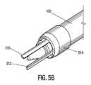
図4Cの参照において、いくつかの実施形態において、切開先端120は、内側シース402に接続され、内部内腔403を通って切開先端に内視鏡116の進行ができる。柔らかい遷移要素414は、切開先端120及びカニューレ本体102の間の形状を滑らかにすることによって切開の間、損傷から組織を保護するために用いられる。遷移要素414の遠位端414Aは、切断部310,312は、図4Dに示されるように遷移要素414を通って遠位に進められるために切開先端120に取り付けないでおかれる。いくつかの実施形態において、遷移要素414は、切開の間、遷移要素414が滑らかな遷移及びまた密閉を作り出し、組織または体の流体がカニューレ100に入ることを防ぐ切開先端に準拠するように柔軟な材料で作られる。他方で、柔軟なスリーブは、切断部310,312が遷移要素414を通って遠位に外に進められることができるように偏向及び伸長できる。いくつかの実施形態において、スリーブの表面は、滑らかな物質で被覆され、切断部310,312及び遷移要素414の間の摩擦を減らすことによって容易に及び滑らかに遷移要素414を通って切断部310,312の伸長を行う。図4Cは、薄い壁収縮チューブ412が、美的な目的のために及び遷移の固定を支援するためにカニューレ本体の外面上に設置されることを描く。4C, in some embodiments, the cutting
図5A及び5Bの参照において、いくつかの実施形態において、切開先端120は、剛性のある材料から作られた遷移要素514を含む。遷移要素514は、2つの切断部310,312が遷移要素514及びカニューレ100から出て延在し(図5Bに示されるように)主カニューレ100に収縮する(図5Aに示すように)ことができる開口または切欠き512を備えて構成される。遷移要素514は、主装置のカニューレ100に接続され、また切開先端120上にある。遷移要素514は、方法の任意の組み合わせを用いてカニューレ100に連結される。例えば、遷移要素514は、機械的接続、接着、溶接などまたはその組み合わせを用いて、カニューレ100に連結される。いくつかの実施形態において、切開先端120及び遷移要素514は、一体である。いくつかの実施形態において、それらは分離した部品として提供される。5A and 5B, in some embodiments, the cutting
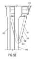
いくつかの実施形態において、遷移要素514のプロファイルは、遠位端に向かって直径が徐々に減少するように成形され、テーパ形状を作り出す。遷移要素514は、単一の成形品または一緒に結合された形の組み合わせから構成される。いくつかの実施形態において、遷移要素514は、切開を通してその形状を維持し、切開負荷を減らす強くて硬い材料で構成される。例えば、手術の間、その剛性によって、遷移要素514は、その形状を維持し、遷移要素514上を滑る組織を支持する。遷移要素に適切な材料は、これに限定されるものではないが、医療グレードの金属及び硬質プラスチックを含む。In some embodiments, the profile of the
さらに図5A及び5Bを参照すると、いくつかの実施形態において、遷移要素514は、2つの切断部310,312が遷移要素514から延在する(図5Bに示されるように)ことができるように設計された切欠き512を含む。切欠き512は、それがカニューレ100内から遷移要素514を通って2つの切断部310,312の通過ができたように配置される。いくつかの実施形態において、切欠き512は、遷移要素514の少なくとも一部を備えて円周方向に延在する曲がった切欠きである。例えば、切欠き512は、カニューレ100の遠位端及び/または先端120の円弧、角度、形状などを鏡に映すような形状にされる。いくつかの実施形態において、切欠き512の円周方向の長さは、切開先端120に対する切断部の回転の範囲を制御する。いくつかの実施形態において、切断部の回転の許容できる円弧は、切欠き512の開口に依存して、完全な回転より小さい。切断部は、切欠き512内に配置され、片面機能を有する、すなわち形状、導電端部312及び平坦な導電端部310(すなわちアンビル)は、それぞれの切断部の内側端部に置かれ、外側端部に置かれない。この構成により、切断要素310,312の1または両方が切欠き512内で回転し、所望の効果(例えば分離、切開など)を達成できる。5A and 5B, in some embodiments, the
動作中、2つの切断部310,312(刃及びアンビル)は伸長されたとき、手術者が装置100の切開先端120の錐体の外の内視鏡116からの視界を示す画面を見るとき、手術者の視野に角度配向を有する。いくつかの実施形態において、アンビル切断部310は、それらがカニューレ100から延在するとき、装置100の本体に対するその角度配向に関して「固定される」。固定されたとき、アンビル切断部310は、常に装置100の「上部」と見なされるものに従ってまたは例えばスライダ及び電源ボタンなど他のユーザ制御に従って延在する。例えば、ユーザが装置100の全体を回転させると、アンビル切断部310は、アンビル切断部が内部で本体に固定されるので、本体と共に回転する。In operation, the two cutting
反対に、刃切断部312は、切開先端120の周りの角度回転に対して本体に固定されない。刃切断部312は、「回転子」機構(例えば回転子サブアセンブリ901)を回転することによって、装置100の中心軸の周りを回転する。回転子は、内部で刃切断部312を回転させるように構成される一方で、アンビル切断部310及び続いて装置100の本体の残りは、固定されたままである。これにより手術者は、アンビル切断部310から刃切断部312を分離できる一方で、焼灼のために枝に近づく。いくつかの実施形態において、切断部310,312は、両方切開先端120の周りを回転可能である。そのような場合において、切開先端120の内面121及び/または外面125は、切断部310,312と共に回転可能に構成され、切断部310,312に従って視覚的な手がかり516を保持する。Conversely, the
上記操作を念頭に置いて、切断部310,312が、収縮される一方で、手術者は、切断部310,312がその前の何かにうっかり接触して引き起こされる損傷がないことを確実にすることができるように、それらを伸長する前に切断部310,312の角度位置を知ることが重要である。With the above operations in mind, while the cutting
図5C-5Eを参照すると、いくつかの実施形態において、切開先端120は、そこに視覚的な手がかり516を含む。視覚的な手がかり516は、切断部の少なくとも1つの場所が切開先端120に対して識別される基準点を指定するように構成される一方で、切断部310,312は、図5Aに示されるように、(例えば遷移要素514の下で)収縮した状態である。同様に、視覚的な手がかり516は、切断部310,312が、収縮の間、カニューレ100に戻って配置される位置を示す。視覚的な手がかり516は、人の目、画像装置またはその組み合わせによって視覚化できるように設計される。Referring to Figures 5C-5E, in some embodiments, the cutting
いくつかの実施形態において、視覚的な手がかり516は、図5Aに示されるように、切開先端120の外面125及び/または先端120の透明部分を通って視覚化される、図5C-5Eに示されるように、切開先端120の内面121に配置される。視覚的な手がかり516は、装置の配向及び/または切断部310,312の場所に関してユーザに十分なインジケータを提供するように長さの任意の組み合わせである。例えば、視覚的な手がかり516は、図5Aに示されるように、先端120の全長または図5Cに示されるように先端の一部上に延在する。In some embodiments, the
図5A-5Eが実線として視覚的な手がかり516を示すが、視覚的な指定の任意の組み合わせが、本発明の範囲から逸脱せずに用いられる。例えば、視覚的な手がかり516は、縦線、横線、矢印、点、点線、曲線、プラス記号など、またはその組み合わせである。同様に、視覚的な手がかり516は、実質的に切開先端102の表面と同一平面上にあるマーク、切開先端102の表面の1つ内の刻み目、切開先端102の表面の1つからの突起、またはその組み合わせを含む任意のタイプの視覚的な指定である。同様に、視覚的な手がかり516は、装置の残りの部分に対して配向の任意の組み合わせを有する。例えば、視覚的な手がかり516は、先端120上を長手方向に伸びるまっすぐな線である。同様に、視覚的な手がかり516は、また切断部310,312の少なくとも1つを位置決めするしるしを提供するように配置される。5A-5E show the
いくつかの実施形態において、視覚的な手がかり516は、十分に視覚化されるような大きさ、形状、色付けがされるが、視野に著しい障害を引き起こさないように十分に小さい。視覚的な手がかり516は、本発明の範囲から逸脱することなく任意の長さであり、例えば視覚的な手がかり516は、図5Aに示されるように、切開先端120の全長に伸びる。同様に、視覚的な手がかり516の透明度は、かろうじて見えるものから完全に不透明なものまで変わる。いくつかの実施形態において、視覚的な手がかり516の場所に依存して、切開先端120及びその部分の透明度も変わる。特に、視覚的な手がかり516が先端120の内面121(または先端120自体の中)に配置されたとき、その後先端120の外面125の少なくとも一部及び/または先端120自体は、視覚的な手がかり516を表示できるほど十分に透明である。例えば、視覚的な手がかり516は、切開先端120の内面121に射出成形中に、作り出され、切開先端120は、図5C-5Eに示されるように、小さい線として識別できるわずかにつや消しされた視覚的な手がかり516を作り出すように透明である。いくつかの実施形態において、視覚的な手がかり516は、それが見えるが視野内に邪魔をしないような長さと幅を備えた大きさ、形状にされる。長さを短く、幅を狭くすることで邪魔にならなくし、視覚的な手がかり516が邪魔しないで急いで容易に見つかるバランスを提供する。視覚的な手がかり516が、先端120の全長に延在しないとき、視覚的な手がかり516は、視覚的に小さく、邪魔をしない先端120の遠位端に設置される。In some embodiments, the
視覚的な手がかり516は、技術分野で既知の方法またはシステムの任意の組み合わせを用いて作り出される。例えば、視覚的な手がかり516は、視覚的な手がかり516が正の突起、負の空洞、または表面仕上げの分裂であり、対照的な光の偏向(例えば、すりガラスなど)を作り出す、切開先端120の表面の射出成形中に作り出される。また、視覚的な手がかり516は、外面125と内面121の任意の組み合わせにエッチングされる。また、外面125と内面121の任意の組み合わせのマークの他の組み合わせが用いられる。例えば、マークは、外面125と内面121の任意の組み合わせ上に、塗装、エンボス加工されるなどである。方法の任意の組み合わせは、視覚的な手がかり516を作り出すために組み合わされる。The
いくつかの実施形態において、視覚的な手がかり516は、内視鏡116からのデータによってデジタルディスプレイ(例えばビデオ画面)上に視覚化されように設計され、切断部310,312の角度位置を識別するために用いられる一方で、それらは収縮した位置にある。画面上の視覚的な手がかり516の視覚化を提供することにより、頭脳が、彼らが見ていない、例えば、触覚の手がかりなど他の手がかりを処理するよりむしろ、ユーザの頭脳が、デジタルディスプレイの視野の視覚的な手がかり516を処理することが容易である。いくつかの実施形態において、視覚的な手がかり516は、用いられる画像システムに基づいて強化された視覚化のために設計される。例えば、視覚的な手がかり516は、蛍光透視鏡システムで見るためのコントラストベースのコーティングを有する。In some embodiments, the
設計に関係なく、いくつかの実施形態において、デジタルディスプレイ上に表示されるように設計された視覚的な手がかり516は、その最も単純な意味で配向され、アンビル切断部310の位置に配置する。例えば、切開先端120のマークは、デジタルディスプレイの投射のための内視鏡または他のカメラによって手術者によって観察され、アンビル切断部310がある(切断部310,312が収縮される間、長手方向に視覚的な手がかり516の背後である)場所を正確に識別する。したがって、ユーザは、切断部310,312を伸ばす際に、アンビル切断部310が、正確に切開先端120の視覚的な手がかり516が配置される筐体から出ることを予期する。また、ユーザは、刃切断部210が常に時計回りまたは反時計回り方向にアンビル切断部310に隣接して配置されることを知る。Regardless of the design, in some embodiments, the
図5D及び5Eを参照すると、装置100の筐体から延在する切断部310,312の例示的な図が示される。図5D及び5Eに示されるように、アンビル切断部310は、軸方向に視覚的な手がかり516と一致し、アンビル切断部310の角度配向のしるしを提供する。したがって、アンビル切断部310(及びアンビル切断部310に対する関係に基づいて刃切断部312)を、筐体から、切欠き512を出て視覚的な手がかり516上に伸ばす場所を投影するために視覚的な手がかり516を信頼する。同様に、またユーザは、刃が常に時計回り方向にアンビルに隣接して配置されることを知る。この構成を用いて、ユーザは、切断部310,312が、本体の意図しない部分に不注意に衝突する心配なく、切断部310,312を正確に配置することができる。いくつかの実施形態において、先端120は、複数の視覚的な手がかり516を含む。例えば、先端120は、切断部310のための分離した視覚的な手がかり516及び切断部312のための分離した視覚的な手がかり516を含む。5D and 5E, an exemplary view of the cutting
いくつかの実施形態において、切断部310,312の少なくとも1つは、実質的に透明な材料から構成され、切断部310,312が視覚的な手がかり516上に配置されたとき、視覚的な手がかり516の視覚化ができる。同様に、切断部310,312の少なくとも1つは、先端120上に視覚的な手がかり516を映すそこに視覚的な手がかり(図示せず)を含む。いくつかの実施形態において、視覚的な手がかり516は、フィードバックの他の形態と組み合わされる。1つの例において、例えば、手術者によって感じられる小さい突起部など触覚応答が、視覚的な手がかり516と組み合わされ、確認の2つの形態を提供する。触覚フィードバックは、方法の任意の組み合わせを含む。例えば、複数の突起部があり、1つは、回転子に添付され、切断部312の角度位置を示し、他は、装置の本体に添付され、切断部310の角度位置を示す。この方法で、手術者は、装置を見てこれらの特徴を配置するためにビデオ画面の焦点を外す必要がない。手術者が画面を見る一方、かれらは手で小さな突起部を単純に感じる。In some embodiments, at least one of the cutting
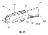
図6Aの参照において、制御ハンドル600は、切断部材を制御するためにカニューレ100の近位端において提供される。いくつかの実施形態において、制御ハンドル600は、切断部材を前進及び後退するための並進制御602を含む。制御ハンドル600は、さらに互いに対して切断部材を回転する回転制御カラー604を含む。制御ハンドル600は、また切断部材の切断部にエネルギ(例えばバイポーラ無線周波数(RF)エネルギ)を供給するためのエネルギ制御606を含む。いくつかの実施形態において、アダプタ114は、カニューレに内視鏡を進めるための制御ハンドル600の近位端600Aに配置される。With reference to FIG. 6A, a
装置の操作は、図6A-6Gを参照して説明される。動作中、初期切開は、従来の方法で作られ、目標血管(例えば伏在静脈)を曝す。カニューレ601(図7B)は、切開に挿入され、目標血管に案内される。いくつかの実施形態において、カニューレ601は、カニューレ601が患者に導入されるポート内にカニューレ601を封止するために細長い本体の周りに滑らかな管状シースを含む。その後、カニューレ100は、実質的に目標血管に沿って進められ、周囲の組織から目標血管を切断する。いくつかの実施形態において、カニューレ601は、切開を封止するために用いられる封止可能なポートを通って導入され、周囲の組織から目標血管の切開によって作り出される空間の吹き込みができる。Operation of the device is described with reference to Figures 6A-6G. In operation, an initial incision is made in a conventional manner to expose a target vessel (e.g., the saphenous vein). A cannula 601 (Figure 7B) is inserted into the incision and guided to the target vessel. In some embodiments, the
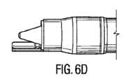
カニューレ100が進められたとき、切断要素の切断部は、図6B-6Gに示されるように枝血管に遭遇するまで、組織切開を邪魔しないように切開先端の近位の収縮位置に保持される。枝血管に到達したとき、切断部310,312は、図6D-6Eに示されるように、遠位にハンドル600の並進制御または滑り制御602を進めることによって切開先端120を超えて遠位方向に動かされる。上記されたように、切断部は、互いに向かって付勢され、一緒に外に進められ、切開先端の内視鏡の視野に入る。As the
次に、切断部は、枝血管を封止及び切断するために、回転制御604を用いて互いから離れて開放形態に回転される。切断部は、円弧動作の切開先端の周りに回転される。内視鏡カニューレは、目標枝血管が、採取される主血管に対する枝血管の配向に関係なく切断部の1つに渡って置くように配置される。内視鏡カニューレは、ユーザが主血管の損傷を避けるために、できる限り目標主血管から離れて内視鏡カニューレと切断部を設置するように設計される。次に、枝血管が切断部310,312の間に配置されたとき、ユーザは切断部を閉じた形態に戻すことができ、その間の枝血管を捕らえる。いくつかの実施形態において、ユーザは、手動で一緒に切断部を持ってくる。代わりにまたはさらに、回転制御は、互いに向かって切断部を付勢するようにばね荷重される。その後、エネルギ制御608ボタンは、枝血管にエネルギを移すように押され、血管を封止する。いくつかの実施形態において、切断部は、切断部が枝血管と接触する前にエネルギを与えられる。封止が完成し、エネルギ制御ボタン608が解放された後、ユーザは、切断部が枝血管を横に切断するまで回転制御604を進め続ける。枝血管が切断されるとすぐに、その後ユーザは、並進制御602によって切断部を収縮し、全ての支流が成功して結紮され横に切断されるまで次の枝血管に装置を進める。The cutting sections are then rotated away from each other to an open configuration using the
いくつかの実施形態において、切断部を付勢するために、制御ハンドル600は、制御カラー604のねじれ動作をばね荷重するための付勢部材605を含む。様々な実施形態において、両方の切断部は回転可能である一方、他の実施形態において、切断部の1つのみは回転可能であり、他の1つは静止する。例えば、カニューレ100は、切断部が閉じた形態で保持されるように、制御ハンドル600と制御カラー604の間のねじれ動作を外部にばね荷重するために構造化され配置される。静脈支流上に切断部を配置するために、制御カラー604は、互いから離れて開放形態に1または両方の切断部を動かすように回転される。制御カラー604の解放のとき所定の量の圧縮力は支流に適用され、続いてバイポーラRFエネルギが活性化され支流を焼灼する。支流の圧縮力は、制御カラー604のばね力選択によって達成され支流封止のプロセスを最適化する。支流を封止するためのバイポーラ焼灼の適用の後、カニューレ100は、回転される及び/または軸方向に変位され支流を切断する。In some embodiments, to bias the cutting sections, the control handle 600 includes a biasing
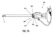
図7A及び7Bの参照において、いくつかの実施形態において、付勢部材605は、制御カラー604の外面に取り付けられた第1の制御レバー610とカニューレ100の制御ハンドル600の外面に取り付けられた対応する第2の制御レバー620を含む。弾性装置または弾性バンド615は、制御レバー610,620を接続するために用いられ、2つを圧縮状態に置くこと及び同様に切断部の間に圧縮力を働かせ切断部を保持することは、閉鎖形態である。7A and 7B, in some embodiments, the biasing
図7C及び7Dの参照において、弾性バンド615は、緩和され収縮した形態であり、切断部を閉鎖形態に保持する。図7E及び7Fの参照において、回転制御604を動かすことは、弾性バンド615を伸ばし、開放形態に切断部を動かす。カラーの解放により弾性バンドは、収縮し、閉鎖形態に切断部を戻すことができる。With reference to Figures 7C and 7D, the
いくつかの実施形態において、付勢部材は、制御ハンドル及び制御カラーの空洞内に配置される。いくつかの実施形態において、付勢部材615は、焼灼及び切断プロセスの間、枝血管に適用される圧縮力を統一するために用いられる。この方法で、採取手術の間、異なる臨床医/ユーザによって働かされる手動の圧縮力の変動は排除され、止血を達成する可能性が増加し、それにより、手術の間の出血(hemorrhage)または出血(bleeding)の可能性を避ける。外部及び内部の付勢切断部は、ユーザが複数の手術を実行するときに実質的に疲れないように、ユーザが焼灼プロセスの期間、反対方向に彼または彼女の手を維持する必要を取り除く。In some embodiments, the biasing members are disposed within the cavities of the control handle and the control collar. In some embodiments, the biasing
いくつかの実施形態において、切断部310,312は、また互いに対して長手方向に移動可能であり、図8A及び8Bに示されるように、枝血管の切断の間達成される切断作用を高める。図8Aに示されるように、切断部310,312は、一緒に切開先端120に沿って遠位に延在する。その後、図8Bに示されるように、ユーザは、伸長位置から「非常に伸長した」位置へ遠位に切断部310,312の1つを並進し続ける。非常に伸長した位置において、切断部310,312の1つは、遠位方向に他の切断部よりさらに進められる。手術プロセスの間、切断部は、焼灼の後、大径の静脈支流を横に切断または切断することは難しい。支流へのバイポーラ焼灼エネルギの適用のとき、支流組織は、乾燥され、生来の状態で想定する柔らかい管状構造よりむしろ硬質の繊維状のストランドに支流組織を変換する。切断部の間の相対並進動作は、「スライス」作用を作りだし、硬い血管さえ切断することを助ける。In some embodiments, the cutting
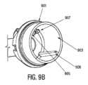
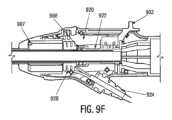
非限定の例として、図9A-9Gは、互いに対して長手方向に切断部の動作を許容する例示のアセンブリを描く。図9Aの参照において、回転子アセンブリ901は、外シース902の近位端に取り付けられる。図9Bに示されるように、回転子アセンブリ901の内区画903は、2つのキー905,906とストッパ907を含み、その目的は以下に記載される。図9Cは、外電極サブアセンブリ920の実施形態を描き、外電極908の近位端に配置される。外電極サブアセンブリ920は、圧縮性要素924によって外電極908に接続される内アダプタ922を含む。内電極904は、外電極908を通って内アダプタ922に延在し、内アダプタ922に固定される。さらに、図9Dに示されるように、外アダプタ926は、外電極908の周りに配置される。外アダプタ926は、内アダプタ922が外電極908に対して回転でき、そのため外電極908に対して内電極904を回転するように設計される。図9Eに示されるように、外電極サブアセンブリ920は、回転子アセンブリ901に挿入され、ハンドル928は、外電極サブアセンブリ920の周りに設置される。9A-9G, by way of non-limiting example, depict exemplary assemblies that permit movement of the cutting sections longitudinally relative to one another. With reference to FIG. 9A, a
動作中、図9Fに示されるように、外電極サブアセンブリ920は、切断部を収縮するために収縮される。切断部を伸長するために、スライダ602は、遠位方向に進められ、遠位方向に外電極サブアセンブリ920を動かす。図9Gに示されるように、外電極サブアセンブリは、外アダプタ926が回転子サブアセンブリ901のストッパ907に押されるまで前に進められる。この点において、切断部は、例えば図8Aに示されるように、一緒に伸長された位置に進められる。次に、スライダ902は、さらに遠位方向に動かされ、圧縮性要素924を圧縮するために内アダプタ922を動かす。内アダプタ922のそのような動作は、またさらに遠位方向に内電極を動かす一方で、外電極908は静止したままである。この方法で、内電極904の切断部は、図8Bに示されるように、非常に伸長した位置に外電極908の切断部に対して長手方向に動かされる。In operation, as shown in FIG. 9F, the
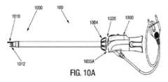
図10A及び10Bの参照において、互いに対して切断部を長手方向に動かす別の実施形態が描かれる。もちろん、図9A-9Gに示される構造は、図10A-10Bの構造と組み合わされることが理解されるべきである。図10Aの参照において、カニューレ100は、制御ハンドル1000から制御カラー1004を分離する間隙1035Aに配置された圧縮性要素または圧縮ばね1035を含む。この形態の一態様は、切断部の間の軸方向の動作を提供する。例えば少なくとも1つの回転切断部1010は、制御カラー1004によって稼働され、約3-5mmまで延ばされ、制御カラー1004は、制御ハンドル1000の前に動かされ、圧縮性要素1035は、制御カラー1004及び制御ハンドル1000の間の間隙1035Aに設置され、そのため制御ハンドル1000に対する制御カラー1004の収縮は、静止刃1012に対して回転切断部1010の3-5mmの軸方向の変位をもたらす。With reference to Figures 10A and 10B, another embodiment is depicted that longitudinally moves the cutting portions relative to one another. Of course, it should be understood that the structures shown in Figures 9A-9G may be combined with the structures of Figures 10A-10B. With reference to Figure 10A, the
図10C及び図10Dは、2つの切断部1010,1012の間の軸方向の動作の使用を描く。例えば、制御カラー1004は、静止切断部1012上に長い回転部1010を閉じるために回転され、バイポーラ電気焼灼は、支流(図10C)を封止するために適用される。閉鎖した圧縮された形態に切断部1010,1012を維持しながら、制御カラー1004は、制御ハンドル1000に対して引き戻され、静止切断部1012に対して長い回転切断部1010を収縮し、2つの切断部1010,1012の間の相対長手方向の動作を提供する(図10D)。10C and 10D depict the use of axial motion between the two cutting
様々な電極への好ましいエネルギのタイプが本開示で示されるが、全ての電極は、これに限定されるものではないが、抵抗加熱、超音波加熱、及びバイポーラまたはモノポーラRFエネルギを含む、様々なエネルギ源を用いてエネルギを与えられることに留意すべきである。いくつかの実施形態において、電極は、互いに独立して制御される。また、必要に応じて、電極は、絶縁コーティングまた絶縁シースで絶縁されることに留意すべきである。Although preferred types of energy for the various electrodes are shown in this disclosure, it should be noted that all electrodes can be energized using a variety of energy sources, including, but not limited to, resistive heating, ultrasonic heating, and bipolar or monopolar RF energy. In some embodiments, the electrodes are controlled independently of one another. It should also be noted that, if desired, the electrodes are insulated with an insulating coating or sheath.
本明細書に引用された全ての特許、特許出願、及び公開された参考文献は、その全てが本明細書に援用される。本開示の上記実施形態は、単なる実施の可能な例であり、単に本開示の原理の明確な理解のために記載されることが強調されるべきである。多くのバリエーション及び改良が、本開示の精神及び原理を実質的に逸脱することなく上記実施形態になされる。本開示の及び他の特徴及び機能のいくつかまたはその代替は、望ましく多くの他の異なるシステムまたは用途に組み合わされることが理解されるであろう。全てのそのような改良及びバリエーションは、添付された特許請求の範囲に含まれるように本開示の範囲内に本明細書に含まれる意図がある。All patents, patent applications, and published references cited herein are hereby incorporated by reference in their entirety. It should be emphasized that the above-described embodiments of the present disclosure are merely possible examples of implementations, and are set forth merely for a clear understanding of the principles of the present disclosure. Many variations and modifications may be made to the above-described embodiments without substantially departing from the spirit and principles of the present disclosure. It will be understood that some or alternatives of the present disclosure and other features and functions may be desirably combined into many other different systems or applications. All such modifications and variations are intended to be included herein within the scope of the present disclosure as set forth in the appended claims.
本明細書に利用されるように、用語「備える」(comprises)及び「備える」(comprising)は、排他的でなく、包含的であるように解釈される意図がある。本明細書で利用されるように、用語「例示的な」(exemplary)、「例の」(example)及び「実例となる」(illustrative)は、「例(example)、例(instance)、実例(illustration)として役立つ」ことを意味する意図があり、他の形態と比較して好ましいまたは有利な形態を示すまたは示さないとして解釈されるべきでない。本明細書で利用されるように、用語「約」(about)、「おおよそ」(generally)、「ほぼ」(approximately)は、例えば特性、パラメータ、大きさ及び寸法の変動など、主観的または客観的な値の範囲の上及び下限に存在する変動を含める意図がある。1つの非限定の例において、用語「約」(about)、「おおよそ」(generally)、及び「ほぼ」(approximately)は、プラス10パーセント以下またはマイナス10パーセント以下を意味する。1つの非限定の例において、用語「約」(about)、「おおよそ」(generally)、及び「ほぼ」(approximately)は、含まれる関連分野で当業者によって見なされるのに十分に近いことを意味する。本明細書で利用されるように、用語「実質的に」は、当業者によって理解されるように、動作、特徴、特性、状態、構造、品物、または結果の完全なまたは完全に近い範囲または度合いを指す。例えば、「実質的に」円形である物体は、物体が当業者によって認識されるまたは理解されるように、数学的に決定できる限界の完全な円またはほぼ円のいずれかを意味するであろう。絶対的な完全性からの正確な許容可能な逸脱の程度は、特定の状況に依存する場合がある。しかしながら、一般的に、完了の近さは、絶対的及び完全な完了が達成または取得されたかのように全体的な結果が同じになるようになる。「実質的に」の使用は、当業者によって理解されるように、動作、特徴、特性、状態、構造、品物、または結果の完全なまたは完全に近い欠如を指すために負の含意に利用されるときに等しく適用できる。As used herein, the terms "comprises" and "comprising" are intended to be interpreted as inclusive, not exclusive. As used herein, the terms "exemplary," "example," and "illustrative" are intended to mean "serving as an example, instance, or illustration," and should not be interpreted as indicating or not indicating a preferred or advantageous form compared to other forms. As used herein, the terms "about," "generally," and "approximately" are intended to include variations that exist at the upper and lower limits of a range of subjective or objective values, such as variations in characteristics, parameters, sizes, and dimensions. In one non-limiting example, the terms "about," "generally," and "approximately" mean plus or minus 10 percent or less. In one non-limiting example, the terms "about," "generally," and "approximately" mean close enough to be considered by one of ordinary skill in the relevant art involved. As used herein, the term "substantially" refers to a perfect or near perfect extent or degree of an operation, feature, characteristic, state, structure, item, or result as would be understood by one of ordinary skill in the art. For example, an object that is "substantially" circular would mean either a perfect circle or a near circle, within mathematically determinable limits, as the object would be recognized or understood by one of ordinary skill in the art. The exact degree of acceptable deviation from absolute perfection may depend on the particular situation. Generally, however, the nearness of completion is such that the overall result would be the same as if absolute and complete completion had been achieved or obtained. The use of "substantially" is equally applicable when utilized in a negative connotation to refer to a complete or near complete lack of an action, feature, characteristic, state, structure, item, or result, as would be understood by one of ordinary skill in the art.
本発明の多数の改良及び代替の実施形態は、前の記載の視点から当業者にとって明白であろう。したがって、本記載は、説明としてのみ解釈されるべきで、当業者に本発明を実行するベストモードを教示する目的のためである。構造の詳細は、本発明の精神から逸脱せずに実質的に変わり、添付された特許請求の範囲の範囲内に入る全ての改良の排他的な使用は、留保される。本明細書で、実施形態は、明確で簡潔な明細書が記載される方法で記載されたが、実施形態は、本発明から離れることなく、様々に組み合わされるまたは分離されることが意図されることが、理解されるであろう。本発明は、添付された特許請求の範囲及び適用可能な法律規則によって要求される範囲にのみ制限されることが意図される。Numerous modifications and alternative embodiments of the present invention will be apparent to those skilled in the art in view of the foregoing description. Accordingly, this description is to be construed as illustrative only and is for the purpose of teaching those skilled in the art the best mode of carrying out the invention. Details of construction may be varied substantially without departing from the spirit of the invention, and the exclusive use of all modifications that come within the scope of the appended claims is reserved. Although embodiments have been described herein in a manner that provides a clear and concise specification, it will be understood that the embodiments are intended to be variously combined or separated without departing from the invention. It is intended that the present invention be limited only to the extent required by the appended claims and applicable rules of law.
また、次の特許請求の範囲は、本明細書に記載された本発明の全ての一般的な及び特定の特徴及び言語の問題として、範囲の中に入ると言われる本発明の範囲の全ての陳述を含むことが理解されるべきである。It is also to be understood that the following claims include all the general and specific features of the invention described herein and, as a matter of language, all statements of the scope of the invention that are said to fall within the scope thereof.
Claims (15)
Translated fromJapanese遠位端に向かって細長い本体内から長手方向に移動可能な第1の切断部と第2の切断部を有する切断ユニットであって、採取される組織を切断するため、少なくとも1つの切断部は、他の切断部に対して前記先端の周りを周方向に移動可能である、切断ユニットと、
前記切断ユニットが、(1)採取しない組織を損傷させるのを防ぎ、(2)切断のために採取する組織に近づくことができるように、前記細長い本体の回転調整を行うため、前記先端に配置され、前記切断ユニットの前記細長い本体内からの出口ポイントを使用者が定める基準点として機能する視覚的な手がかりと、を備える手術装置。 an elongated body terminating in a transparent tip at a distal end of the body;
a cutting unit having a first cutting portion and a second cutting portion longitudinally movable from within the elongate body toward a distal end, at least one cutting portion being circumferentially movable about the tip relative to the other cutting portion to cut the tissue to be harvested;
and a visual cue located at the distal end to function as a reference point for a user to define an exit point of the cutting unit from within the elongated body to (1) prevent the cutting unit from damaging tissue that is not to be harvested, and (2) facilitate rotational adjustment of the elongated body so that the cutting unit can approach tissue that is to be harvested for cutting.
前記付勢部材は、前記回転制御カラーに連結して前記切断部を前記閉鎖位置に戻す、請求項9に記載の手術装置。 and a rotational control collar disposed at a proximal end of the elongate body for moving the cutting portion from the closed position to the open position.
The surgical device of claim 9 , wherein the biasing member is coupled to the rotation control collar to return the cutting section to the closed position.
前記第1の切断部の鋭い端部に面する前記第2の切断部の端部は、平坦である、請求項1に記載の手術装置。 the first cutting portion has a sharp end;
The surgical device of claim 1 , wherein an end of the second cutting portion facing a sharp end of the first cutting portion is flat.
Applications Claiming Priority (3)
| Application Number | Priority Date | Filing Date | Title |
|---|---|---|---|
| US201962841413P | 2019-05-01 | 2019-05-01 | |
| US62/841,413 | 2019-05-01 | ||
| PCT/US2020/030674WO2020223463A1 (en) | 2019-05-01 | 2020-04-30 | Unitary endoscopic vessel harvesting devices with a visual cue to identify cutting elements orientation |
Publications (2)
| Publication Number | Publication Date |
|---|---|
| JP2022531272A JP2022531272A (en) | 2022-07-06 |
| JP7624125B2true JP7624125B2 (en) | 2025-01-30 |
Family
ID=73016960
Family Applications (1)
| Application Number | Title | Priority Date | Filing Date |
|---|---|---|---|
| JP2021564652AActiveJP7624125B2 (en) | 2019-05-01 | 2020-04-30 | Single endoscopic vessel harvesting device with visual cues to identify cutting element orientation - Patents.com |
Country Status (5)
| Country | Link |
|---|---|
| US (2) | US20200345408A1 (en) |
| EP (1) | EP3962377A4 (en) |
| JP (1) | JP7624125B2 (en) |
| CN (1) | CN113784673A (en) |
| WO (1) | WO2020223463A1 (en) |
Families Citing this family (6)
| Publication number | Priority date | Publication date | Assignee | Title |
|---|---|---|---|---|
| WO2014158613A1 (en) | 2013-03-14 | 2014-10-02 | Saphena Medical, Inc. | Unitary endoscopic vessel harvesting devices |
| US11432839B2 (en)* | 2018-01-12 | 2022-09-06 | Maquet Cardiovascular Llc | Vessel harvesting apparatus and method |
| WO2020206266A1 (en) | 2019-04-05 | 2020-10-08 | Saphena Medical, Inc. | Unitary device for vessel harvesting and method of using same |
| JP7569840B2 (en) | 2019-08-14 | 2024-10-18 | エルエスアイ ソルーションズ インコーポレーテッド | Device for blood vessel harvesting |
| US20220233270A1 (en)* | 2021-01-22 | 2022-07-28 | Lsi Solutions, Inc. | Minimally invasive surgical device for vessel harvesting |
| CN119564298B (en)* | 2025-02-10 | 2025-05-09 | 武汉大学中南医院 | Ureter cutting device under peritoneoscope |
Citations (1)
| Publication number | Priority date | Publication date | Assignee | Title |
|---|---|---|---|---|
| JP2016209549A (en) | 2015-04-28 | 2016-12-15 | サフィナ・メディカル・インコーポレイテッドSaphena Medical, Inc. | Single endoscopic blood vessel collection device with elastic force |
Family Cites Families (11)
| Publication number | Priority date | Publication date | Assignee | Title |
|---|---|---|---|---|
| US5209749A (en)* | 1990-05-11 | 1993-05-11 | Applied Urology Inc. | Fluoroscopically alignable cutter assembly and method of using the same |
| US5350391A (en)* | 1992-10-19 | 1994-09-27 | Benedetto Iacovelli | Laparoscopic instruments |
| US6726677B1 (en)* | 1995-10-13 | 2004-04-27 | Transvascular, Inc. | Stabilized tissue penetrating catheters |
| US6440138B1 (en)* | 1998-04-06 | 2002-08-27 | Kyphon Inc. | Structures and methods for creating cavities in interior body regions |
| US7485092B1 (en) | 1998-08-12 | 2009-02-03 | Maquet Cardiovascular Llc | Vessel harvesting apparatus and method |
| US20040147909A1 (en)* | 2002-12-20 | 2004-07-29 | Gyrus Ent L.L.C. | Surgical instrument |
| US20060271082A1 (en)* | 2005-05-31 | 2006-11-30 | Kirchhevel G Lamar | Calibrated surgical probe |
| ATE536135T1 (en)* | 2006-12-22 | 2011-12-15 | Spectranetics Corp | EXPOSABLE SEPARATION SYSTEMS |
| AU2007203086A1 (en)* | 2007-07-02 | 2009-01-22 | Origin Medsystems, Inc. | Endoscopic vessel harvesting system components |
| DE102011075781A1 (en)* | 2011-05-13 | 2012-11-15 | Karl Storz Gmbh & Co. Kg | Electrosurgical instrument |
| US20170354433A1 (en)* | 2016-06-14 | 2017-12-14 | Next Step Consulting, LLC | Device for plantar fascia endoscopy and soft tissue releases |
- 2020
- 2020-04-30WOPCT/US2020/030674patent/WO2020223463A1/ennot_activeCeased
- 2020-04-30EPEP20799040.9Apatent/EP3962377A4/enactivePending
- 2020-04-30USUS16/862,966patent/US20200345408A1/enactivePending
- 2020-04-30CNCN202080032145.3Apatent/CN113784673A/enactivePending
- 2020-04-30JPJP2021564652Apatent/JP7624125B2/enactiveActive
- 2025
- 2025-01-15USUS19/023,168patent/US20250152232A1/enactivePending
Patent Citations (1)
| Publication number | Priority date | Publication date | Assignee | Title |
|---|---|---|---|---|
| JP2016209549A (en) | 2015-04-28 | 2016-12-15 | サフィナ・メディカル・インコーポレイテッドSaphena Medical, Inc. | Single endoscopic blood vessel collection device with elastic force |
Also Published As
| Publication number | Publication date |
|---|---|
| WO2020223463A1 (en) | 2020-11-05 |
| EP3962377A1 (en) | 2022-03-09 |
| JP2022531272A (en) | 2022-07-06 |
| US20200345408A1 (en) | 2020-11-05 |
| US20250152232A1 (en) | 2025-05-15 |
| EP3962377A4 (en) | 2023-01-25 |
| CN113784673A (en) | 2021-12-10 |
Similar Documents
| Publication | Publication Date | Title |
|---|---|---|
| JP7624125B2 (en) | Single endoscopic vessel harvesting device with visual cues to identify cutting element orientation - Patents.com | |
| JP7242752B2 (en) | single endoscope angiography device | |
| US20240252196A1 (en) | Unitary Endoscopic Vessel Harvesting Devices | |
| US11751896B2 (en) | Unitary endoscopic vessel harvesting devices | |
| EP3087927B1 (en) | Unitary endoscopic vessel harvesting devices with an elastic force | |
| US20130197299A1 (en) | Unitary Endoscopic Vessel Harvesting Devices | |
| US9119900B2 (en) | Unitary endoscopic vessel harvesting devices | |
| US20250160871A1 (en) | Unitary endoscopic vessel harvesting devices | |
| US11432839B2 (en) | Vessel harvesting apparatus and method | |
| EP3310277B1 (en) | Unitary endoscopic vessel harvesting devices |
Legal Events
| Date | Code | Title | Description |
|---|---|---|---|
| A621 | Written request for application examination | Free format text:JAPANESE INTERMEDIATE CODE: A621 Effective date:20230427 | |
| A131 | Notification of reasons for refusal | Free format text:JAPANESE INTERMEDIATE CODE: A131 Effective date:20231212 | |
| A977 | Report on retrieval | Free format text:JAPANESE INTERMEDIATE CODE: A971007 Effective date:20231215 | |
| A521 | Request for written amendment filed | Free format text:JAPANESE INTERMEDIATE CODE: A523 Effective date:20240305 | |
| A131 | Notification of reasons for refusal | Free format text:JAPANESE INTERMEDIATE CODE: A131 Effective date:20240319 | |
| A521 | Request for written amendment filed | Free format text:JAPANESE INTERMEDIATE CODE: A523 Effective date:20240618 | |
| A02 | Decision of refusal | Free format text:JAPANESE INTERMEDIATE CODE: A02 Effective date:20240716 | |
| A521 | Request for written amendment filed | Free format text:JAPANESE INTERMEDIATE CODE: A523 Effective date:20241017 | |
| A521 | Request for written amendment filed | Free format text:JAPANESE INTERMEDIATE CODE: A821 Effective date:20241017 | |
| A911 | Transfer to examiner for re-examination before appeal (zenchi) | Free format text:JAPANESE INTERMEDIATE CODE: A911 Effective date:20241108 | |
| TRDD | Decision of grant or rejection written | ||
| A01 | Written decision to grant a patent or to grant a registration (utility model) | Free format text:JAPANESE INTERMEDIATE CODE: A01 Effective date:20241126 | |
| RD03 | Notification of appointment of power of attorney | Free format text:JAPANESE INTERMEDIATE CODE: A7423 Effective date:20241206 | |
| A61 | First payment of annual fees (during grant procedure) | Free format text:JAPANESE INTERMEDIATE CODE: A61 Effective date:20241212 | |
| A521 | Request for written amendment filed | Free format text:JAPANESE INTERMEDIATE CODE: A821 Effective date:20241206 | |
| RD04 | Notification of resignation of power of attorney | Free format text:JAPANESE INTERMEDIATE CODE: A7424 Effective date:20241210 | |
| R150 | Certificate of patent or registration of utility model | Ref document number:7624125 Country of ref document:JP Free format text:JAPANESE INTERMEDIATE CODE: R150 |