JP7622552B2 - Color confirmation system, color confirmation method, and program - Google Patents
Color confirmation system, color confirmation method, and programDownload PDFInfo
- Publication number
- JP7622552B2 JP7622552B2JP2021091296AJP2021091296AJP7622552B2JP 7622552 B2JP7622552 B2JP 7622552B2JP 2021091296 AJP2021091296 AJP 2021091296AJP 2021091296 AJP2021091296 AJP 2021091296AJP 7622552 B2JP7622552 B2JP 7622552B2
- Authority
- JP
- Japan
- Prior art keywords
- observer
- display
- image
- color
- chart
- Prior art date
- Legal status (The legal status is an assumption and is not a legal conclusion. Google has not performed a legal analysis and makes no representation as to the accuracy of the status listed.)
- Active
Links
- 238000012790confirmationMethods0.000titleclaimsdescription132
- 238000000034methodMethods0.000titleclaimsdescription60
- 230000006870functionEffects0.000claimsdescription137
- 230000003595spectral effectEffects0.000claimsdescription106
- 238000006243chemical reactionMethods0.000claimsdescription66
- 230000005855radiationEffects0.000claimsdescription36
- 239000003086colorantSubstances0.000claimsdescription19
- 238000012795verificationMethods0.000claimsdescription13
- 230000004044responseEffects0.000claimsdescription3
- 238000010586diagramMethods0.000description29
- 238000004891communicationMethods0.000description25
- 230000008569processEffects0.000description19
- 238000003384imaging methodMethods0.000description17
- 230000001815facial effectEffects0.000description13
- 239000011159matrix materialSubstances0.000description9
- 238000012545processingMethods0.000description9
- 239000000284extractSubstances0.000description7
- 238000004364calculation methodMethods0.000description5
- 230000035945sensitivityEffects0.000description3
- 102100031235Chromodomain-helicase-DNA-binding protein 1Human genes0.000description2
- 102100031266Chromodomain-helicase-DNA-binding protein 3Human genes0.000description2
- 101000777047Homo sapiens Chromodomain-helicase-DNA-binding protein 1Proteins0.000description2
- 101000777071Homo sapiens Chromodomain-helicase-DNA-binding protein 3Proteins0.000description2
- 230000008859changeEffects0.000description2
- 239000000463materialSubstances0.000description2
- 238000012986modificationMethods0.000description2
- 230000004048modificationEffects0.000description2
- 230000004456color visionEffects0.000description1
- 238000012937correctionMethods0.000description1
- 238000013461designMethods0.000description1
- 238000003745diagnosisMethods0.000description1
- 230000000694effectsEffects0.000description1
- 238000005516engineering processMethods0.000description1
- 238000005286illuminationMethods0.000description1
- 239000004973liquid crystal related substanceSubstances0.000description1
- 238000005259measurementMethods0.000description1
- 230000003287optical effectEffects0.000description1
- 238000005457optimizationMethods0.000description1
- 230000002093peripheral effectEffects0.000description1
- 238000000611regression analysisMethods0.000description1
- 230000009466transformationEffects0.000description1
- 230000001960triggered effectEffects0.000description1
Images


Landscapes
- Color Image Communication Systems (AREA)
- Spectrometry And Color Measurement (AREA)
- Image Processing (AREA)
Description
Translated fromJapanese本発明は、色確認システム、色確認方法、及びプログラムに関する。The present invention relates to a color confirmation system, a color confirmation method, and a program.
従来、対象物を撮像した画像を遠隔地に送信し、遠隔地にてディスプレイに画像を表示させ、その対象物の色を確認することが広く行われている(例えば、特許文献1、及び非特許文献1参照)。Conventionally, it is common to capture an image of an object, transmit it to a remote location, and display the image on a display at the remote location to check the color of the object (see, for example,
ディスプレイを介して対象物の色を確認しようとすると、対象物の物体色とディスプレイ色との色の見えの個人差により、色を正しく確認することが困難となる場合がある。また、ディスプレイを介して色を確認する場合、従来の印刷物の色確認に用いられてきたような色見本や校正刷りなどの実物が用いられることがないと考えられる。このため、ディスプレイを介して色を確認する場合においては、色の確認が正しく行われたか否かを、後から確認することが難しいという問題がある。When checking the color of an object through a display, it may be difficult to check the color correctly due to individual differences in how the object color and the display color appear. Furthermore, when checking colors through a display, it is thought that actual items such as color samples or proof copies, which have been used to check the colors of conventional printed materials, are not used. For this reason, when checking colors through a display, there is the problem that it is difficult to check later whether the color was checked correctly or not.
上述の課題を鑑み、本発明の目的は、ディスプレイを介して対象物の色を確認する場合における、色の見えの個人差に対応することができる色確認システム、色確認方法、及びプログラムを提供することにある。In view of the above-mentioned problems, the object of the present invention is to provide a color confirmation system, a color confirmation method, and a program that can accommodate individual differences in color appearance when checking the color of an object via a display.
上述の課題を解決するために、本発明の一態様に係る色確認システムは、ディスプレイに表示された画像を観察する観察者を、観察者データベースに登録する観察者登録部と、前記ディスプレイを介して、観察対象とする対象物が示された画像を観察する観察者を前記観察者データベースから選択する観察者選択部と、前記ディスプレイを介して前記対象物が示された画像を観察する場合における、前記対象物を観察する観察光源を選択する観察光源選択部と、前記対象物が撮像された対象物画像と同一の撮像条件にて撮像された、チャートが撮像されたチャート画像、前記観察光源選択部によって選択された観察光源、前記観察者選択部によって選択された観察者に応じた等色関数、及び前記ディスプレイの色特性、のそれぞれを用いて、前記対象物画像の色が前記ディスプレイに表示する色に変換されたディスプレイ表示用画像を生成する画像変換部と、前記ディスプレイ表示用画像を前記ディスプレイに表示する画像表示部と、を備え、前記チャート画像に示されているチャートは、分光反射率が既知であって、前記チャートの分光反射率が、チャートの分光反射率データベースに記憶され、前記ディスプレイの色特性は、ディスプレイ特性データベースに記憶され、前記観察光源は、観察光源データベースに記憶され、前記観察者選択部によって選択された観察者に応じた等色関数は、複数の等色関数が記憶された等色関数データベースから選択される。In order to solve the above-mentioned problems, a color confirmation system according to one aspect of the present invention includes an observer registration unit that registers an observer who observes an image displayed on a display in an observer database, an observer selection unit that selects an observer who observes an image showing an object to be observed via the display from the observer database, an observation light source selection unit that selects an observation light source for observing the object when observing the image showing the object via the display, and a color matching function according to a chart image in which a chart is captured under the same imaging conditions as an object image in which the object is captured, the observation light source selected by the observation light source selection unit, and the observer selected by the observer selection unit. , and the color characteristics of the display, to generate an image for display in which the color of the object image is converted into the color to be displayed on the display, and an image display unit displays the image for display on the display, wherein the chart shown in the chart image has a known spectral reflectance, the spectral reflectance of the chart is stored in a chart spectral reflectance database, the color characteristics of the display are stored in a display characteristic database, the viewing light source is stored in a viewing light source database, and a color matching function according to the viewer selected by the viewer selection unit is selected from a color matching function database in which a plurality of color matching functions are stored.
本発明の一態様に係る色確認方法は、観察者登録部が、ディスプレイに表示された画像を観察する観察者を、観察者データベースに登録し、観察者選択部が、前記ディスプレイを介して、観察対象とする対象物が示された画像を観察する観察者を前記観察者データベースから選択し、観察光源選択部が、前記ディスプレイを介して前記対象物が示された画像を観察する場合における、前記対象物を観察する観察光源を選択し、画像変換部が、前記対象物が撮像された対象物画像と同一の撮像条件にて撮像された、チャートが撮像されたチャート画像、前記観察光源選択部によって選択された観察光源、前記観察者選択部によって選択された観察者に応じた等色関数、及び前記ディスプレイの色特性、のそれぞれを用いて、前記対象物画像の色が前記ディスプレイに表示する色に変換されたディスプレイ表示用画像を生成し、画像表示部が、前記ディスプレイ表示用画像を前記ディスプレイに表示する、色確認方法であって、前記チャート画像に示されているチャートは、分光反射率が既知であって、前記チャートの分光反射率が、チャートの分光反射率データベースに記憶され、前記ディスプレイの色特性は、ディスプレイ特性データベースに記憶され、前記観察光源は、観察光源データベースに記憶され、前記観察者選択部によって選択された観察者に応じた等色関数は、複数の等色関数が記憶された等色関数データベースから選択される。In one aspect of the present invention, a color confirmation method includes an observer registration unit that registers an observer who observes an image displayed on a display in an observer database, an observer selection unit that selects an observer who observes an image showing an object to be observed via the display from the observer database, an observation light source selection unit that selects an observation light source for observing the object when the image showing the object is observed via the display, and an image conversion unit that converts a chart image of a chart captured under the same imaging conditions as an object image of the object, the observation light source selected by the observation light source selection unit, a color matching function corresponding to the observer selected by the observer selection unit, and the previous A color confirmation method in which an image for display is generated in which the color of the object image is converted into the color to be displayed on the display using each of the color characteristics of the display, and an image display unit displays the image for display on the display, wherein the chart shown in the chart image has a known spectral reflectance, the spectral reflectance of the chart is stored in a chart spectral reflectance database, the color characteristics of the display are stored in a display characteristic database, the viewing light source is stored in a viewing light source database, and a color matching function corresponding to the viewer selected by the viewer selection unit is selected from a color matching function database in which a plurality of color matching functions are stored.
本発明の一態様に係るプログラムは、コンピュータを、ディスプレイに表示された画像を観察する観察者を、観察者データベースに登録する観察者登録部と、前記ディスプレイを介して、観察対象とする対象物が示された画像を観察する観察者を前記観察者データベースから選択する観察者選択部と、前記ディスプレイを介して前記対象物が示された画像を観察する場合における、前記対象物を観察する観察光源を選択する観察光源選択部と、前記対象物が撮像された対象物画像と同一の撮像条件にて撮像された、チャートが撮像されたチャート画像、前記観察光源選択部によって選択された観察光源、前記観察者選択部によって選択された観察者に応じた等色関数、及び前記ディスプレイの色特性、のそれぞれを用いて、前記対象物画像の色が前記ディスプレイに表示する色に変換されたディスプレイ表示用画像を生成する画像変換部と、前記ディスプレイ表示用画像を前記ディスプレイに表示する画像表示部と、として機能させる、プログラムであって、前記チャート画像に示されているチャートは、分光反射率が既知であって、前記チャートの分光反射率が、チャートの分光反射率データベースに記憶され、前記ディスプレイの色特性は、ディスプレイ特性データベースに記憶され、前記観察光源は、観察光源データベースに記憶され、前記観察者選択部によって選択された観察者に応じた等色関数は、複数の等色関数が記憶された等色関数データベースから選択される、プログラム。A program according to one aspect of the present invention includes a computer, an observer registration unit that registers an observer who observes an image displayed on a display in an observer database, an observer selection unit that selects from the observer database an observer who observes an image showing an object to be observed via the display, an observation light source selection unit that selects an observation light source for observing the object when observing an image showing the object via the display, and a chart image in which a chart is captured under the same imaging conditions as an object image in which the object is captured, an observation light source selected by the observation light source selection unit, a color matching function corresponding to the observer selected by the observer selection unit, and a color characteristic of the display. and an image display unit that displays the image for display on the display, the chart shown in the chart image having a known spectral reflectance, the spectral reflectance of the chart being stored in a chart spectral reflectance database, the color characteristics of the display being stored in a display characteristic database, the viewing light source being stored in a viewing light source database, and a color matching function corresponding to the viewer selected by the viewer selection unit being selected from a color matching function database in which a plurality of color matching functions are stored.
本発明によれば、ディスプレイを介して対象物の色を確認する場合における、色の見えの個人差に対応することができる。The present invention can accommodate individual differences in color perception when checking the color of an object through a display.
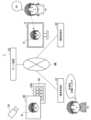
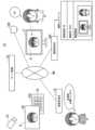
以下、実施形態の色確認システム1を、図面を参照しながら説明する。図1は、第1の実施形態に係る色確認システム1の概要を示すブロック図である。色確認システム1は、撮像者SUの依頼に応じて、遠隔にいる観察者KUが対象物Bの色を、ディスプレイDを介して確認するシステムである。The
図1に示すように、色確認システム1は、例えば、撮像者端末10と、サーバ装置20と、観察者端末30とを備える。色確認システム1の構成要素(撮像者端末10、サーバ装置20、及び観察者端末30)は、通信ネットワークNWを介して通信可能に接続されている。As shown in FIG. 1, the
撮像者端末10は、撮像者SUの端末装置である。撮像者端末10は、例えば、PC(Personal Computer)、タブレット端末、或いはスマートフォンなどである。撮像者SUは、対象物Bの色の確認を依頼する側のユーザである。対象物Bは、任意の物体であってよい。例えば、対象物Bは、カラーの印刷物や人の肌など、色を確認する必要が生じ得る物体である。The image-
撮像者SUは、カメラCAで対象物Bを撮像する。カメラCAは、デジタルカメラ、スマートフォンに内蔵されたカメラ(後述する撮像部15)など、一般的な撮像機能を備えた装置である。カメラCAが、撮像者端末10とは別体の撮像装置である場合、カメラCAと撮像者端末10をUSBケーブルで接続する等して、カメラCAが撮像した画像(対象物画像BG)を撮像者端末10に取り込む。The photographer SU captures an image of the object B with the camera CA. The camera CA is a device with a general imaging function, such as a digital camera or a camera built into a smartphone (the
また、撮像者SUは、対象物Bを撮像した撮像条件と同じ条件下において、チャートCHを撮像する。ここでの撮像条件とは、撮像が行われた条件であって、例えば、撮像時の照明や、カメラCAの露出等のカメラパラメータの設定値である。チャートCHは、分光反射率が既知の色が示されている物体であれば任意のチャートであってよい。対象物Bの色の範囲がある程度限定されている場合、その対象物Bが取り得る色の範囲の分光反射率に近いパッチを有するチャートが用いられてもよい。また、対象物Bがある程度限定され、分光的な特徴がある程度限定される場合には、分光的な特徴が対象物Bに近いパッチを有するチャートが用いられてもよい。The photographer SU also captures the chart CH under the same imaging conditions as those under which the object B was captured. The imaging conditions here refer to the conditions under which the image was captured, such as the lighting at the time of capturing the image and the settings of camera parameters such as the exposure of the camera CA. The chart CH may be any chart as long as it is an object that exhibits a color with a known spectral reflectance. If the color range of the object B is somewhat limited, a chart having patches with spectral reflectances close to the range of colors that the object B can take may be used. If the object B is somewhat limited and its spectral characteristics are also somewhat limited, a chart having patches with spectral characteristics close to those of the object B may be used.
なお、撮像条件に変更がなければ、チャートCHの撮像を1回行えばよい。対象物Bを撮像する度に、チャートCHを撮像する必要はない。If there are no changes to the imaging conditions, it is sufficient to image the chart CH once. There is no need to image the chart CH every time the object B is imaged.
撮像者端末10は、対象物Bが撮像された画像(対象物画像BG)、及びチャートCHが撮像された画像(チャート画像CHG)を、サーバ装置20に送信する。The
サーバ装置20は、撮像者SUからの依頼と観察者KUによる確認とを仲介するコンピュータ装置である。サーバ装置20は、例えば、サーバ装置、クラウド、PCなどである。サーバ装置20は、観察者KU、及び観察者端末30の環境に応じて、対象物画像BGの色を変換した画像(後述する、ディスプレイ表示用画像)を生成する。サーバ装置20が、ディスプレイ表示用画像を生成する方法については、後で詳しく説明する。サーバ装置20は、ディスプレイ表示用画像を、観察者端末30に送信する。The
観察者端末30は、観察者KUの端末装置である。観察者端末30は、例えば、サーバ装置、PC、タブレット端末、或いはスマートフォンなどである。観察者KUは、対象物Bの色の確認する側のユーザである。The
観察者KUは、観察者KUを特定する情報を入力する。例えば、観察者端末30の表示画面に、データベース(後述する観察者DB222)に登録された観察者のリストが表示される。観察者KUは、画面に表示されたリストから観察者自身に該当する氏名等を選択することにより、観察者KUを特定する情報を入力する。The observer KU inputs information that identifies the observer KU. For example, a list of observers registered in a database (
また、観察者KUは、観察光源を選択する。ここでの観察光源は、対象物Bを観察する観察光源として観察者KUにより選択される光源である。例えば、観察者KUは、対象物Bを「自然光」の光源下で観察したい場合には、観察光源として「自然光」を選択する。The observer KU also selects an observation light source. The observation light source here is a light source selected by the observer KU as the observation light source for observing the object B. For example, if the observer KU wants to observe the object B under a light source of "natural light", the observer KU selects "natural light" as the observation light source.
観察者端末30は、観察者KUにより入力された情報(観察者KUを特定する情報)及び、観察者KUにより選択された観察光源を示す情報を、サーバ装置20に送信する。観察者端末30は、サーバ装置20からディスプレイ表示用画像を受信し、受信した画像をディスプレイDに表示する。観察者KUは、ディスプレイDに表示された画像の色を確認する。The
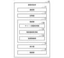
図2は、第1の実施形態に係る撮像者端末10の構成例を示すブロック図である。撮像者端末10は、例えば、通信部11と、記憶部12と、制御部13と、表示部14と、撮像部15とを備える。FIG. 2 is a block diagram showing an example of the configuration of the
通信部11は、サーバ装置20及び観察者端末30と通信を行う。例えば、通信部11は、サーバ装置20に、対象物画像BG、及びチャート画像CHGを送信する。The
記憶部12は、HDD、フラッシュメモリ、EEPROM(Electrically Erasable Programmable Read Only Memory)、RAM(Random Access read/write Memory)、ROM(Read Only Memory)などの記憶媒体、あるいはこれらの組合せによって構成される。記憶部12は、撮像者端末10の各種処理を実行するためのプログラム、及び各種処理を行う際に利用される一時的なデータを記憶する。The
制御部13は、撮像者端末10がハードウェアとして備えるCPU(Central Processing Unit)にプログラムを実行させることによって実現される。制御部13は、撮像者端末10を統括的に制御する。制御部13は、通信部11、記憶部12、表示部14、及び撮像部15のそれぞれを制御する。The
制御部13は、例えば、チャート画像取得部130と、物体画像取得部131と、装置制御部132とを備える。チャート画像取得部130は、例えば、撮像部15(カメラCA)からチャート画像CHGを取得し、取得した画像を装置制御部132に出力する。物体画像取得部131は、撮像部15(カメラCA)から対象物画像BGを取得し、取得した画像を装置制御部132に出力する。装置制御部132は、撮像者端末10を統合的に制御する。装置制御部132は、例えば、チャート画像取得部130から取得したチャート画像CHG、及び物体画像取得部131から取得した対象物画像BGのそれぞれを、通信部11を介して、サーバ装置20に送信する。The
表示部14は、液晶ディスプレイなどの表示装置を含み、制御部13の制御に応じて、対象物画像BGやチャート画像CHGを表示する。The
撮像部15は、画像を撮像する撮像装置を含み、制御部13の制御に応じて、対象物B、及びチャートCHなどの画像を撮像する。The
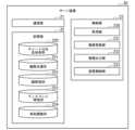
図3は、第1の実施形態に係るサーバ装置20の構成例を示すブロック図である。サーバ装置20は、例えば、通信部21と、記憶部22と、制御部23とを備える。FIG. 3 is a block diagram showing an example of the configuration of the
通信部21は、撮像者端末10及び観察者端末30と通信を行う。例えば、通信部21は、撮像者端末10から、対象物画像BG及びチャート画像CHGを受信する。また、通信部21は、観察者端末30に、ディスプレイ表示用画像を送信する。The
記憶部22は、HDD、フラッシュメモリ、EEPROM、RAM、ROMなどの記憶媒体、あるいはこれらの組合せによって構成される。記憶部22は、サーバ装置20の各種処理を実行するためのプログラム、及び各種処理を行う際に利用される一時的なデータを記憶する。The
記憶部22は、例えば、チャート分光反射率DB220と、観察光源DB221と、観察者DB222と、ディスプレイ特性DB223と、等色関数DB224とを記憶する。The
チャート分光反射率DB220は、チャートCHの分光反射率が記憶されたデータベースである(図5参照)。Chart spectral reflectance DB220 is a database that stores the spectral reflectance of chart CH (see Figure 5).
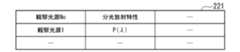
観察光源DB221は、対象物Bを観察する観察光源の分光放射分布が記憶されたデータベースである(図6参照)。ここでの観察光源は、対象物Bを観察する観察光源であり、例えば、観察者KUにより選択される光源である。例えば、観察者KUは、対象物Bを「自然光」の光源下で観察したい場合には、観察光源として「自然光」を選択する。The observation light source DB221 is a database that stores the spectral radiation distribution of the observation light source for observing the object B (see FIG. 6). The observation light source here is the observation light source for observing the object B, and is, for example, a light source selected by the observer KU. For example, when the observer KU wants to observe the object B under a light source of "natural light", he selects "natural light" as the observation light source.
なお、上記では、観察光源DB221に記憶された観察光源が、対象物Bを観察する観察光源として選択される場合を例示したが、これに限定されない。観察光源DB221に記憶された観察光源が、ディスプレイDが設けられた空間を照明する光源の情報として利用されてもよい。In the above, the observation light source stored in the observation light source DB221 is selected as the observation light source for observing the object B, but the present invention is not limited to this. The observation light source stored in the observation light source DB221 may be used as information on a light source for illuminating the space in which the display D is installed.
観察者DB222は、観察者KUが記憶されたデータベースである(図7参照)。ディスプレイ特性DB223は、ディスプレイDの特性(色特性)が記憶されたデータベースである(図8参照)。等色関数DB224は、等色関数が記憶されたデータベースである(図9参照)。The observer DB222 is a database in which the observer KU is stored (see FIG. 7). The display characteristic DB223 is a database in which the characteristics (color characteristics) of the display D are stored (see FIG. 8). The color matching function DB224 is a database in which color matching functions are stored (see FIG. 9).
なお、図9の例では等色関数DB224には、観察者KUごとの等色関数が記憶された例が示されているが、これに限定されることはない。等色関数DB224は、代表的な等色関数が、複数記憶されたデータベースであってもよい。In the example of FIG. 9, the color
ここで、チャート分光反射率DB220は、「チャート分光反射率データベース」の一例である。観察光源DB221は、「観察光源データベース」の一例である。観察者DB222は、「観察者データベース」の一例である。ディスプレイ特性DB223は、「ディスプレイ特性データベース」の一例である。等色関数DB224は、「等色関数データベース」の一例である。Here, the chart spectral reflectance DB220 is an example of a "chart spectral reflectance database". The viewing illuminant DB221 is an example of an "viewing illuminant database". The observer DB222 is an example of an "observer database". The display characteristics DB223 is an example of a "display characteristics database". The color matching function DB224 is an example of a "color matching function database".
制御部23は、サーバ装置20がハードウェアとして備えるCPUにプログラムを実行させることによって実現される。制御部23は、サーバ装置20を統括的に制御する。制御部23は、通信部21、記憶部22のそれぞれを制御する。The
制御部23は、例えば、取得部230と、画像変換部231と、画像出力部232と、装置制御部233とを備える。取得部230は、撮像者SUにより撮像された画像、すなわち対象物画像BG及びチャート画像CHGを取得し、取得した画像を画像変換部231に出力する。また、取得部230は、観察者KUにより選択された観察光源を示す情報を取得し、取得した情報を画像変換部231に出力する。また、取得部230は、観察者KUの情報を取得し、取得した情報を画像変換部231に出力する。ここで取得部230により画像変換部231に出力された観察者KUの情報は、例えば、画像変換時に観察者の等色関数を特定するために用いられる。The
画像変換部231は、画像変換を行う。ここでの画像変換とは、観察者KU、及び観察者端末30の環境に応じて、対象物画像BGの色を変換することである。以下、ディスプレイ表示用画像を生成する方法について説明する。The
(ディスプレイ表示用画像を生成する方法)
ディスプレイ表示用画像生成手順(1):画像変換部231は、チャートCHにおける各パッチの測色値を算出する。測色値は色空間上の座標値である。画像変換部231は、チャート分光反射率DB220を参照して、チャートCHの分光反射率を取得する。画像変換部231は、観察光源DB221を参照して、観察者KUにより選択された観察光源の分光放射分布を取得する。また、画像変換部231は、等色関数DB224を参照して、観察者KUの等色関数を取得する。画像変換部231は、取得した情報、すなわち、チャートCHの分光反射率、観察光源の分光放射分布、及び観察者KUの等色関数を用いて、チャートCHの各パッチの測色値を算出する。(Method of generating an image for display)
Display image generating procedure (1): The
ディスプレイ表示用画像生成手順(2):画像変換部231は、チャート画像CHGの各パッチに対応する部分の画素の画素値(例えば、RGB値)と、ディスプレイ表示用画像生成手順(1)で算出した各パッチの測色値とを用いて、例えば、重回帰分析等により、画素値(例えば、RGB値)から測色値を算出するためのマトリックス(変換行列)を算出する。Display image generation procedure (2): The
ディスプレイ表示用画像生成手順(3):画像変換部231は、ディスプレイ特性DB223を参照して、ディスプレイDのディスプレイ特性を取得する。画像変換部231は、取得したディスプレイ特性と、観察者KUの等色関数とを用いて、ディスプレイDのデバイス値(例えば、RGB値)と、測色値の関係を記述する色変換テーブルを算出する。デバイス値は、ディスプレイDに色を表示する際に、ディスプレイDに入力される値である。Display image generation procedure (3): The
ここでの色変換テーブルは、例えば、多次元のルックアップテーブルである。この場合、画像変換部231は、例えば、ディスプレイ特性として、RGBの各チャンネル(画素値)を、適当な間隔で均等に分割する。画像変換部231は、例えば、RGB値を、5刻みで、画素値0~255を分割した51段階とする。画像変換部231は、51段階に分割した、各々のRGB値の組み合わせに対して、表示色の分光放射分布が、ディスプレイ特性DB223に記述されている場合、その分光放射分布に対して、観察者KUの等色関数を用いて、それぞれの測色値を算出する。これにより、画像変換部231は、RGB値を均等な間隔で分割したそれぞれの領域に対する測色値が記述された多次元ルックアップテーブルを生成することができる。ディスプレイ特性DB223に記述されたディスプレイ特性が、画像変換部が設定した分割と異なる場合、画像変換部231は、補間計算などにより、設定した分割に対応するRGB値に対する分光放射分布を求めて計算を行ってもよい。The color conversion table here is, for example, a multidimensional lookup table. In this case, the
或いは、色変換テーブルは、階調再現曲線と、変換行列で構成されてもよい。この場合、画像変換部231は、ディスプレイ特性DB223に記述された特性から、RGB各チャンネルの階調に対応する分光放射分布(RGBそれぞれの階調255、すなわちRGBの原色に対応するデータも含む)を取得する。画像変換部231は、その取得した分光分布に対して、観察者KUの等色関数を用いて、それぞれの測色値を算出する。これにより、画像変換部231は、RGB各チャンネルの階調に対応する測色値から階調再現曲線を、また、RGBの各原色に対応する測色値から変換行列をそれぞれ求めることができる。Alternatively, the color conversion table may be composed of a tone reproduction curve and a conversion matrix. In this case, the
画像変換部231は、算出した色変換テーブルを用いて、測色値をディスプレイDのデバイス値(例えば、RGB値)に変換する変換テーブルを算出する。色変換テーブルが多次元のルックアップテーブルである場合、画像変換部231は、測色値(例えばXYZの三刺激値)の色空間を、均等に分割する。画像変換部231は、色空間を分割したそれぞれの格子点に相当する測色値(例えばXYZ値)に対して、ディスプレイDを介して、その測色値を再現するためのデバイス値(例えば、RGB値)を、上記の多次元ルックアップテーブルを用いて検索する。検索には、例えば、最適化手法などを用いることが考えられる。画像変換部231は、検索結果に基づいて、表示したい測色値に対応するディスプレイDのデバイス値(例えば、RGB値)を算出するテーブルを生成することができる。色変換テーブルが階調再現曲線と、変換行列で構成されている場合、画像変換部231は変換行列の逆行列を算出することにより、測色値からデバイス値の計算が可能となる。The
ディスプレイ表示用画像生成手順(4):画像変換部231は、対象物画像BGの画素値(例えば、RGB値)を、ディスプレイ表示用画像生成手順(2)で算出したマトリックスを用いて、測色値に変換する。そして、画像変換部231は、ディスプレイ表示用画像生成手順(3)で算出した変換テーブル、または、階調直線とマトリックスを用いて、測色値を、ディスプレイDのデバイス値(例えば、RGB値)に変換する。Display image generation procedure (4): The
画像変換部231は、対象物画像BGの画素値(例えば、RGB値)を、ディスプレイDのデバイス値(例えば、RGB値)に変換した画像を、ディスプレイ表示用画像として生成する。画像変換部231は、生成したディスプレイ表示用画像を、画像出力部232に出力する。The
画像出力部232は、ディスプレイ表示用画像を、出力する。The
装置制御部233は、サーバ装置20を統合的に制御する。例えば、装置制御部233は、通信部21が撮像者端末10から受信した、対象物画像BG及びチャート画像CHGを、取得部230に出力する。また、装置制御部233は、通信部21が、観察者端末30から受信した、観察者KUを特定する情報及び観察光源を示す情報を、取得部230に出力する。装置制御部233は、画像出力部232が出力したディスプレイ表示用画像を、通信部21を介して、観察者端末30に送信する。The
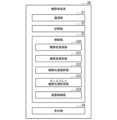
図4は、第1の実施形態に係る観察者端末30の構成例を示すブロック図である。観察者端末30は、例えば、通信部31と、記憶部32と、制御部33と、表示部34と、を備える。通信部31は、サーバ装置20及び撮像者端末10と通信を行う。例えば、通信部31は、サーバ装置20に、観察者KUを特定する情報、及び観察者KUにより選択された観察光源を示す情報を送信する。また、通信部31は、サーバ装置20から、ディスプレイ表示用画像を、受信する。FIG. 4 is a block diagram showing an example of the configuration of the
記憶部32は、HDD、フラッシュメモリ、EEPROM、RAM、ROMなどの記憶媒体、あるいはこれらの組合せによって構成される。記憶部32は、観察者端末30の各種処理を実行するためのプログラム、及び各種処理を行う際に利用される一時的なデータを記憶する。The
制御部33は、観察者端末30がハードウェアとして備えるCPUにプログラムを実行させることによって実現される。制御部33は、撮像者端末10を統括的に制御する。制御部33は、通信部31、記憶部32、及び表示部34のそれぞれを制御する。The
表示部34は、LCDモニタ、有機ELなど、一般的な自発光型のディスプレイなどの表示装置を含み、制御部33の制御に応じて、観察者KUを登録する画面、観察者KUを選択する画面、観察光源を選択する画面、及び、ディスプレイ表示用画像などを表示する。The
制御部33は、例えば、観察者登録部330と、観察者選択部331と、観察光源選択部332と、ディスプレイ観察光源取得部333と、装置制御部334とを備える。The
観察者登録部330は、予め観察者KUを登録する。例えば、観察者KUは、観察者端末30と接続されたキーボード等の入力装置を用いて、観察者KU特定する情報、例えば氏名、ID、等色関数、顔写真等を示す情報を操作入力する。観察者登録部330は、観察者KUにより操作入力された観察者KU特定する情報を取得し、取得した情報を、サーバ装置20に送信する。サーバ装置20に送信された情報(観察者KU特定する情報)は、サーバ装置20によって、例えば、観察者DB222に登録される。The
観察者選択部331は、観察者KUを選択する。例えば、観察者KUは、観察者端末30の表示部34に表示されたリスト(観察者DB222に登録された観察者のリスト)を視認する。観察者KUは、キーボード等の入力装置を用いて、リストから自身を選択する。これにより、選択された観察者KUを示す情報が、観察者端末30に通知される。観察者選択部331は、観察者KUにより選択された観察者KU自身を示す情報を取得し、取得した情報を、サーバ装置20に送信する。The
或いは、観察者選択部331は、観察者KUのIDを取得することによって、観察者KUを選択するようにしてもよい。この場合、色確認システム1は、色確認を行う際に、例えば、観察者KUのIDを用いたログインを必要とするシステムである。観察者端末30は、色確認システム1にログインする際に観察者KUにより操作入力された、観察者KUのIDを取得する。観察者選択部331は、観察者端末30に入力されたIDに基づいて、観察者DB222から観察者KUを選択する。Alternatively, the
観察光源選択部332は、観察光源を選択する。例えば、観察者KUは、観察者端末30の表示部34に表示されたリスト(対応可能な観察光源、例えば、観察光源DB221に登録された観察光源のリスト)を視認する。観察者KUは、キーボード等の入力装置を用いて、リストから対象物Bを観察したい観察光源を選択する。これにより、観察者KUにより選択された観察光源を示す情報が、観察者端末30に通知される。観察者選択部331は、観察者KUにより選択された観察光源を示す情報を取得し、取得した情報を、サーバ装置20に送信する。The observation light
ディスプレイ観察光源取得部333が行う処理については、後述する第2の実施形態の変形例にて、詳しく説明する。The processing performed by the display observation light
装置制御部334は、観察者端末30を統合的に制御する。例えば、装置制御部334は、観察者登録部330により登録された観察者KUの氏名等を示す情報を、通信部21を介して、サーバ装置20に送信する。装置制御部334は、観察者選択部331により選択された観察者KUを特定する情報を、通信部21を介して、サーバ装置20に送信する。また、装置制御部334は、観察光源選択部332により選択された観察光源を示す情報を、通信部21を介して、サーバ装置20に送信する。装置制御部334は、通信部21がサーバ装置20から受信した、ディスプレイ表示用画像を、表示部34に出力する。The
図5は、第1の実施形態に係るチャート分光反射率DB220の例を示す図である。チャート分光反射率DB220は、例えば、チャートCHごとに生成される。チャート分光反射率DB220は、例えば、パッチNo、分光反射特性などの項目を備える。パッチNoは、チャートCHに示されたパッチを一意に特定する番号等の識別情報である。分光反射特性は、パッチNoにて特定されるパッチの分光反射特性を示す情報であり、例えば、分光反射率を示す情報である。Figure 5 is a diagram showing an example of the chart spectral reflectance DB220 according to the first embodiment. The chart spectral reflectance DB220 is generated, for example, for each chart CH. The chart spectral reflectance DB220 includes items such as patch number and spectral reflectance characteristics. The patch number is identification information such as a number that uniquely identifies a patch shown on the chart CH. The spectral reflectance characteristics is information indicating the spectral reflectance characteristics of the patch identified by the patch number, for example, information indicating the spectral reflectance.
図6は、第1の実施形態に係る観察光源DB221の例を示す図である。観察光源DB221は、例えば、観察光源No、分光放射特性などの項目を備える。観察光源Noは、観察光源を一意に特定する番号等の識別情報である。分光放射特性は、観察光源Noにて特定される観察光源の分光放射特性を示す情報であり、例えば、分光放射分布を示す情報である。Figure 6 is a diagram showing an example of the observation light source DB221 according to the first embodiment. The observation light source DB221 includes items such as the observation light source No. and the spectral radiation characteristics. The observation light source No. is identification information such as a number that uniquely identifies the observation light source. The spectral radiation characteristics is information indicating the spectral radiation characteristics of the observation light source identified by the observation light source No., for example, information indicating the spectral radiation distribution.
図7は、第1の実施形態に係る観察者DB2221の例を示す図である。観察者DB222は、例えば、観察者No、氏名、ID、等色関数、顔写真などの項目を備える。観察者Noは、観察者KUを一意に特定する番号等の識別情報である。IDは、観察者Noで特定される観察者KUのID(Identification)を示す情報である。等色関数は、観察者Noで特定される観察者KUの等色関数を示す情報である。顔写真は、観察者Noで特定される観察者KUの顔写真を示す情報である。Figure 7 is a diagram showing an example of an observer DB 2221 according to the first embodiment. The
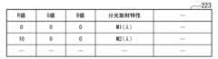
図8は、第1の実施形態に係るディスプレイ特性DB223の例を示す図である。ディスプレイ特性DB223は、例えば、ディスプレイDごとに生成される。ディスプレイ特性DB223は、例えば、R値、G値、B値、及び分光放射特性などの項目を備える。R値は、ディスプレイDの各画素に表示する画素値のうちの赤色(Red)成分の値である。G値は、ディスプレイDの各画素に表示する画素値のうちの緑色(Green)成分の値である。B値は、ディスプレイDの各画素に表示する画素値のうちの青色(Blue)成分の値である。分光放射特性は、R値、G値、及びB値にて特定される画素値(RGB値)に対応してディスプレイDにより放射される光の分光放射特性を示す情報であり、例えば、分光放射分布を示す情報である。FIG. 8 is a diagram showing an example of the display
この図の例では、画素値(0、0、0)に対応するディスプレイDの分光放射特性は、M1(λ)であることが示されている。また、画素値(10、0、0)に対応するディスプレイDの分光放射特性は、M2(λ)であることが示されている。ここでのλは波長を示す。In the example of this figure, it is shown that the spectral radiation characteristic of display D corresponding to pixel value (0, 0, 0) is M1(λ). It is also shown that the spectral radiation characteristic of display D corresponding to pixel value (10, 0, 0) is M2(λ). Here, λ indicates wavelength.
図9は、第1の実施形態に係る等色関数DB224の例を示す図である。等色関数DB224は、例えば、観察者No、等色関数などの項目を備える。観察者Noは、観察者KUを一意に特定する番号等の識別情報である。等色関数は、観察者Noにより特定される観察者KUの等色関数を示す情報であり、例えば、X特性、Y特性、Z特性からなる三刺激値を示す情報である。FIG. 9 is a diagram showing an example of the color
この図の例では、観察者No(観察者U1)にて特定される観察者KUの等色関数は、X特性がx1(λ)、Y特性がy1(λ)、Z特性がz1(λ)であることが示されている。また、観察者No(観察者U2)にて特定される観察者KUの等色関数は、X特性がx2(λ)、Y特性がy2(λ)、Z特性がz2(λ)であることが示されている。ここでのλは波長を示す。In the example of this figure, the color matching functions of observer KU identified by observer No. (observer U1) are shown to have an X characteristic of x1 (λ), a Y characteristic of y1 (λ), and a Z characteristic of z1 (λ). Also, the color matching functions of observer KU identified by observer No. (observer U2) are shown to have an X characteristic of x2 (λ), a Y characteristic of y2 (λ), and a Z characteristic of z2 (λ). Here, λ indicates wavelength.
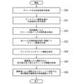
図10は、第1の実施形態に係る色確認システム1が行う処理の流れを示すフローチャートである。Figure 10 is a flowchart showing the flow of processing performed by the
まず、色確認システム1は、チャートCHを撮像する(ステップS10)。例えば、撮像者SUがカメラCAを操作することにより、チャートCHを撮像する。これにより、撮像者端末10は、チャート画像CHGを取得し、取得したチャート画像CHGを、サーバ装置20に送信する。なお、撮像条件、例えば、撮像対象を照明する光源、及び、撮像に用いる画像入力装置(カメラCA)や、その画像入力装置のカメラパラメータの設定等を変更しない限り、このステップS10は1度行えばよく、後段のステップS11において対象物Bを撮像する度に、ステップS10を繰り返し行う必要はない。First, the
次に、色確認システム1は、対象物Bを撮像する(ステップS11)。例えば、撮像者SUがカメラCAを操作することにより、チャートCHを撮像した撮像条件と同じ条件下で、対象物Bを撮像する。これにより、撮像者端末10は、対象物画像BGを取得し、取得した対象物画像BGを、サーバ装置20に送信する。Next, the
色確認システム1は、観察者KUを登録する(ステップS12)。このステップS12は、図10に示す一連のフローとは別に、事前に行われる処理ステップであってもよい。例えば、観察者KUが、観察者端末30に、観察者KUを登録するための情報、例えば、氏名、ID、及び等色関数等を、入力操作する。これにより、観察者端末30は、観察者KUを登録するための情報を取得し、取得した情報を、サーバ装置20に送信する。The
サーバ装置20は、ステップS12で観察者端末30から取得した、観察者KUを登録するための情報を、観察者DB222に記憶することによって、観察者KUを登録する。また、サーバ装置20は、ステップS12で、観察者KUの等色関数を取得した場合には、取得した等色関数を、その観察者KUに対応づけて、等色関数DB224に記憶する。The
色確認システム1は、観察者KUを選択する(ステップS13)。例えば、観察者KUが、観察者端末30に表示された観察者の一覧を示すリストから、自身を選択する。これにより、観察者端末30は、観察者KUを特定するための情報を取得し、取得した情報を、サーバ装置20に送信する。The
色確認システム1は、観察光源を選択する(ステップS14)。例えば、観察者KUが、観察者端末30に表示された観察光源の一覧を示すリストから、対象物Bを観察したい観察光源を選択する。これにより、観察者端末30は、観察光源を特定するための情報を取得し、取得した情報を、サーバ装置20に送信する。The
なお、観察光源DB221には、対象物Bの観察に使用する可能性がある観察光源が予め記憶されており、観察光源DB221に記憶された情報に基づいて、観察者端末30の表示部34に観察光源の一覧を示すリストが表示される。In addition, the observation light source DB221 stores in advance the observation light sources that may be used to observe the object B, and based on the information stored in the observation light source DB221, a list of the observation light sources is displayed on the
色確認システム1は、対象物画像BGを変換する(ステップS15)。具体的に、色確認システム1は、ステップS10で撮像されたチャート画像CHGの分光反射率を、チャート分光反射率DB220から取得する。色確認システム1は、ステップS11で撮像された対象物画像BGの各画素の画素値を取得する。色確認システム1は、ステップS13で選択された観察者KUの等色関数を、等色関数DB224から取得する。色確認システム1は、ステップS14で選択された観察光源の分光放射分布を、観察光源DB221から取得する。また、色確認システム1は、ディスプレイDの特性を、ディスプレイ特性DB223から取得する。そして、色確認システム1は、上述したディスプレイ表示用画像生成手順(1)~ディスプレイ表示用画像生成手順(4)により、対象物画像BGの色をディスプレイ表示用画像に色に変換することによって、ディスプレイ表示用画像を生成する。The
色確認システム1は、ディスプレイ表示用画像を表示する(ステップS16)。色確認システム1は、ステップS15でサーバ装置20によって生成された生成したディスプレイ表示用画像を、観察者端末30に送信する。観察者端末30は、サーバ装置20から受信したディスプレイ表示用画像を、表示部34に表示する。The
以上、説明したように、第1の実施形態に係る色確認システム1は、観察者登録部330と、観察者選択部331と、観察光源選択部332と、画像変換部231と、表示部34(「画像表示部」の一例)とを備える。観察者登録部330は、観察者KUを、観察者DB222(観察者データベース)に登録する。観察者KUは、ディスプレイDに表示された画像を観察する観察者である。観察者選択部331は、ディスプレイDを介して、対象物が示された画像(ディスプレイ表示用画像)を観察する観察者KUを、観察者DB222から選択する。観察光源選択部332は、観察者KUが、ディスプレイDを介して対象物が示された画像(ディスプレイ表示用画像)を観察する場合における、対象物Bを観察する観察光源を選択する。画像変換部231は、ディスプレイ表示用画像を生成する。ディスプレイ表示用画像は、対象物画像BGの色がディスプレイDに表示する色に変換された画像である。画像変換部231は、対象物画像BGと同一の撮像条件にて撮像されたチャート画像CHG、観察光源選択部332によって選択された観察光源、観察者選択部331によって選択された観察者KUに応じた等色関数、及びディスプレイDの色特性を用いて、ディスプレイ表示用画像を生成する。表示部34は、ディスプレイ表示用画像を表示する。なお、チャート画像CHGに示されているチャートCHは、分光反射率が既知であって、チャート分光反射率DB220(チャート分光反射率データベース)にそのチャートCHの分光反射率が記憶されているチャートである。ディスプレイDの色特性は、ディスプレイ特性DB223(ディスプレイ特性データベース)に記憶されている。観察光源は、観察光源DB221(観察光源データベース)に記憶されている。観察者選択部331によって選択された観察者KUに応じた等色関数は、等色関数DB224(等色関数データベース)から選択されたものである。等色関数DB224には、複数の等色関数が記憶されている。As described above, the
これにより、第1の実施形態に係る色確認システム1では、観察者KUの等色関数を用いて、ディスプレイ表示用画像を生成することができる。このため、ディスプレイDを介して対象物の色を確認する場合における、色の見えの個人差に対応することができる。As a result, in the
また、第1の実施形態に係る色確認システム1では、等色関数DB224に、観察者DB222に登録された観察者ごとに、その観察者の等色関数が記憶されていてもよい。この場合、画像変換部231は、等色関数DB224を用いて、観察者KU(観察者選択部331によって選択された観察者)の等色関数を選択する。これにより、第1の実施形態に係る色確認システム1では、観察者KUのそれぞれに応じた等色関数を選択することができ、観察者KUの見えに応じて、ディスプレイ表示用画像を生成することができる。In addition, in the
また、第1の実施形態に係る色確認システム1では、等色関数DB224に、代表的なの等色関数が複数記憶されていてもよい。この場合、画像変換部231は、等色関数DB224を用いて、観察者KUの等色関数を選択する。これにより、第1の実施形態に係る色確認システム1では、上述した実施形態と同様の効果を奏する。In addition, in the
また、第1の実施形態に係る色確認システム1では、観察者DB222には、ID(観察者DB222に登録された観察者KUを一意に識別する観察者ID)が記憶されていてもよい。この場合、観察者選択部331は、観察者KUによって操作入力されたIDに応じて、観察者KU(ディスプレイDを介して対象物画像を観察する観察者)を選択する。これにより、第1の実施形態に係る色確認システム1では、観察者KUがIDを入力するという容易な方法にて観察者KUを選択することができる。In addition, in the
(第1の実施形態の変形例)
ここで、第1の実施形態の変形例について説明する。本変形例では、観察者登録部330が、観察者KUの等色関数を決定する点において、上述した実施形態と相違する。(Modification of the first embodiment)
Here, a modified example of the first embodiment will be described. This modified example differs from the above-described embodiment in that the
図11は、第1の実施形態の変形例に係る色確認システム1の概要を示す図である。図11に示すように、本変形例では、観察者KUが、登録を行う際に、分光反射率が既知のチャートCH#を所持する。Figure 11 is a diagram showing an overview of a
ここでのチャートCH#は、第1に実施形態において、撮像者SUによって撮像されたチャートCHと同一のチャートであってもよいし、異なるチャートであってもよい。また、チャートCH#は、対象物Bの分光反射特性が反映されたパッチからなるカラーチャートであってもよい。チャートCH#は、反射物体であってよいし、自発光物体であってもよい。また、チャートCH#は、観察対象とする対象物Bが分光的に再現された印刷物であってもよい。以下では、チャートCH#が反射物体である場合を例に、説明する。The chart CH# here may be the same chart as the chart CH captured by the photographer SU in the first embodiment, or it may be a different chart. The chart CH# may also be a color chart made up of patches that reflect the spectral reflectance characteristics of the object B. The chart CH# may be a reflective object or a self-luminous object. The chart CH# may also be a printed material in which the object B to be observed is spectrally reproduced. The following will explain an example in which the chart CH# is a reflective object.
観察者端末30は、観察者KUの等色関数を決定するための複数の判定画像CHD(判定画像CHD1~CHD3…)を、ディスプレイDに表示する。判定画像CHDは、チャートCH#における各パッチの色が、複数の等色関数のそれぞれに対応した色に変換された画像である。以下、判定画像CHDを生成する方法について説明する。The
(判定画像CHDを生成する方法)
判定画像CHD生成手順(1):観察者登録部330は、チャートCH#の分光反射率を取得する。観察者登録部330は、チャート分光反射率DB220を参照して、チャートCH#の分光反射率を取得してもよいし、他のデータベースを参照してチャートCH#の分光反射率を取得してもよい。(Method of generating judgment image CHD)
Procedure for generating judgment image CHD (1): The
判定画像CHD生成手順(2):ディスプレイ観察光源取得部333は、ディスプレイ観察光源を取得する。ディスプレイ観察光源は、例えばディスプレイDを観察する環境に設けられた光源であり、観察者KUが所持するチャートCH#を照明する光源である。Procedure for generating judgment image CHD (2): The display observation light
ディスプレイ観察光源取得部333は、例えば、観察者端末30の表示部34に表示されたリスト(対応可能な観察光源、例えば、観察光源DB221に登録された観察光源のリスト)を表示する。観察者KUは、観察者端末30の表示部34に表示されたリストから、ディスプレイ観察光源を取得する。例えば、観察者KUは、ディスプレイDが設置された部屋が、蛍光灯によって照明された部屋である場合、ディスプレイ観察光源として「蛍光灯」を選択する。ディスプレイ観察光源取得部333は、観察者KUにより選択されたディスプレイ観察光源を示す情報を取得し、取得した情報を、観察者登録部330に出力する。The display observation light
或いは、ディスプレイ観察光源取得部333は、画像から、ディスプレイ観察光源を示す情報を取得するようにしてもよい。例えば、後述するディスプレイ観察環境画像取得部335によって、ディスプレイDを観察する環境の全天周画像が取得された場合、ディスプレイ観察光源取得部333は、全天周画像に示されているチャートCH#の色に基づいて、ディスプレイ観察光源の分光放射分布を推定し、推定した分光放射分布を持つ光源を、ディスプレイ観察光源として、観察者登録部330に出力する。Alternatively, the display observation light
判定画像CHD生成手順(3):観察者登録部330は、判定画像CHD生成手順(1)で取得したチャートCH#の分光反射率、判定画像CHD生成手順(2)で取得したディスプレイ観察光源、及び、対応させる等色関数を用いて、下記(1)式に示すように、チャートCH#における各パッチの測色値(X1、Y1、Z1)を算出する。Judgment image CHD generation procedure (3): The
X1=∫R(λ)P(λ)x1(λ)dλ
Y1=∫R(λ)P(λ)y1(λ)dλ
Z1=∫R(λ)P(λ)z1(λ)dλ
…(1)
但し、
R(λ)は、チャートCH#のパッチにおける分光反射率
P(λ)は、ディスプレイ観察光源における分光放射分布
(x1(λ)、y1(λ)、z1(λ))は、観察者U1の等色関数
λは波長 X1=∫R(λ)P(λ)x1(λ)dλ
Y1=∫R(λ)P(λ)y1(λ)dλ
Z1=∫R(λ)P(λ)z1(λ)dλ
…(1)
however,
R(λ) is the spectral reflectance of the patch of chart CH#. P(λ) is the spectral radiance distribution of the display observation light source. (x1(λ), y1(λ), z1(λ)) are the spectral reflectance distribution of the observer U1. Color matching function λ is wavelength
判定画像CHD生成手順(4):観察者登録部330は、ディスプレイDの表示色(例えば、RGB値)と、測色値の関係を記述する色変換テーブルを算出する。変換テーブルを算出する方法は、上述したディスプレイ表示用画像生成手順(3)と同様であるため、その説明を省略する。Procedure for generating judgment image CHD (4): The
判定画像CHD生成手順(5):観察者登録部330は、判定画像CHD生成手順(3)で算出したチャートCH#の各パッチの測色値を、判定画像CHD生成手順(4)で算出した変換テーブルを用いて、ディスプレイDの表示色(例えば、RGB値)に変換する。観察者登録部330は、変換したディスプレイDの表示色を、観察者KUの等色関数に対応するチャートCHの各パッチの色として、ディスプレイDに表示する。Judgment image CHD generation procedure (5): The
観察者登録部330は、観察者の等色関数を変更しながら、上記、判定画像CHD生成手順(1)~判定画像CHD生成手順(5)の手順を繰り返し行い、複数の観察者のそれぞれの等色関数に対応する、チャートCH#が示された複数の判定画像CHD(判定画像CHD1~CHD3…)を生成し、生成した画像を、ディスプレイDに表示する。The
観察者KUは、ディスプレイDに表示された複数の判定画像CHDと、手元にあるチャートCH#の色とを見比べて、手元にあるチャートCH#の色と、色の見えが最も近いと感じる判定画像CHDを選択する。観察者登録部330は、観察者KUにより選択された判定画像CHDを示す情報を取得し、取得した判定画像CHDに対応する等色関数を、その観察者KUの等色関数と決定する。観察者端末30は、観察者登録部330により決定された観察者KUの等色関数を示す情報を、サーバ装置20に送信する。サーバ装置20は、観察者端末30から取得した、観察者KUの等色関数を示す情報を、観察者DB222に記憶する。The observer KU compares the multiple judgment images CHD displayed on the display D with the colors of the chart CH# in front of him/her, and selects the judgment image CHD that he/she feels has the closest color appearance to the color of the chart CH# in front of him/her. The
図12は、第1の実施形態の変形例に係る色確認システム1が行う処理の流れを示すフローチャートである。色確認システム1は、例えば、チャート分光反射率DB220を参照してチャートCH#の分光反射率を取得する(ステップS20)。色確認システム1は、例えば、観察者KUにより選択された光源を示す情報に基づいて、観察光源DB221を参照することにより、ディスプレイ観察光源の分光放射分布を取得する(ステップS21)。色確認システム1は、チャートCH#の分光反射率、及びディスプレイ観察光源の分光放射分布に基づいて、等色関数DB224に記憶された等色関数ごとに、チャートCH#の各パッチの測色値を算出する(ステップS22)。色確認システム1は、ディスプレイ特性DB223に記憶されたディスプレイDの色特性と、等色関数DB224に記憶された等色関数に基づいて、測色値をディスプレイDの表示色に変換する変換テーブルを算出し、算出した変換テーブルを用いて、チャートCH#における各パッチの測色値を、等色関数に対応するディスプレイDの表示色に変換する(ステップS23)。FIG. 12 is a flowchart showing the flow of processing performed by the
色確認システム1は、ディスプレイDの表示色に変換したチャートCH#における各パッチの色を示す画像(判定画像CHD)を、ディスプレイDに表示する(ステップS24)。色確認システム1は、観察者KUにより選択された判定画像CHDを示す情報を取得する(ステップS25)。ここで、観察者KUに選択される画像は、手元のチャートCH#の色と、色の見えが最も近いと観察者KUが感じた判定画像CHDである。色確認システム1は、観察者KUにより選択された判定画像CHDに対応する等色関数を、その観察者KUの等色関数に決定する(ステップS26)。The
ここで、観察者KUに、判定画像CHDを表示させるバリエーションについて説明する。観察者KUの等色関数を精度よく決定するためには、観察者KUにとって色が近いと感じる判定画像CHDが、適切に選択される必要がある。一方で、例えば、等色関数DB224に多数の等色関数が記憶されている場合には、それぞれの等色関数に対応する判定画像CHDが多数生成されることとなるため、多数の判定画像CHDから、観察者KUにとって色が近いと感じる判定画像CHDを効率よく決定する必要がある。このように、観察者KUにとって色が近いと感じる判定画像CHDを、状況に応じて、精度よく、或いは効率よく選択する必要がある。このため、判定画像CHDをディスプレイDに表示させる場合において、表示を工夫する。Here, variations in displaying the judgment image CHD to the observer KU will be described. In order to accurately determine the color matching function for the observer KU, it is necessary to appropriately select a judgment image CHD that the observer KU perceives as similar in color. On the other hand, for example, when a large number of color matching functions are stored in the color
図13~図16は、第1の実施形態の変形例に係る色確認システム1が判定画像CHDを表示する処理を説明する図である。Figures 13 to 16 are diagrams explaining the process by which a
図13に示すように、例えば、観察者登録部330は、ディスプレイDに、複数の判定画像CHDを並べて表示する。観察者KUは、手元にあるチャートCH#と、ディスプレイDに表示された複数の判定画像CHDのそれぞれを比較して、最も色が近いと感じる判定画像CHDを選択する。観察者登録部330は、観察者KUによって選択された判定画像CHDの算出に使用した等色関数を、その観察者の等色関数として決定する。As shown in FIG. 13, for example, the
図14に示すように、観察者登録部330は、ディスプレイDに、複数の判定画像CHDの中から選択した、一つの判定画像CHDを、順次表示するようにしてもよい。例えば、観察者登録部330は、観察者KUのキーボード操作やマウス操作等により、ディスプレイDに表示された画像を順送り、或いは逆送りにして、判定画像CHDを切り替えて表示させることが可能にする。観察者KUは、例えば、手元にあるチャートCH#と、判定画像CHDを切り替えて表示させながら比較して、最も色が近いと感じる画像を選択する。観察者登録部330は、観察者KUによって選択された判定画像CHDの算出に使用した等色関数を、その観察者の等色関数として決定する。As shown in FIG. 14, the
図15に示すように、観察者登録部330は、ディスプレイDに、複数の判定画像CHDの中から選択した、二つの判定画像CHDを、表示するようにしてもよい。観察者KUは、左右の二つの判定画像CHDと、手元にあるチャートCH#とを比較して、色が近いと感じる方の判定画像CHDを選択する。観察者登録部330は、選択された判定画像CHDを残して、選択されなかった方の画像を、次の判定画像CHDに切り替えて表示する(勝ち残り)。すなわち、観察者登録部330は、観察者KUに選択された判定画像CHDを残しながら、順次、残りの判定画像CHDを表示させる操作を行い、この操作をすべての判定画像CHDで繰り返す。これにより、観察者登録部330は、最終的に観察者KUによって選択された判定画像CHDを決定する。観察者登録部330は、決定した判定画像CHDの算出に使用した等色関数を、観察者KUの等色関数として決定する。As shown in FIG. 15, the
或いは、観察者登録部330は、複数の判定画像CHDの中から選択した、二つの判定画像CHDの組(ペア)を事前に生成しておく。そして、図15の例に示すように、生成したペアのうちの一つのペアを、ディスプレイDに表示する。観察者KUは、ディスプレイDに表示された左右の画像と、手元にあるチャートCH#とを比較して、色が近いと感じる画像を選択する。観察者登録部330は、事前に生成した全てのペアのそれぞれについて、観察者KUに色が近いと感じる画像を選択させる。観察者登録部330は、事前に生成した全てのペアのそれぞれについて、観察者KUに選択された画像を抽出し、抽出した画像を用いて、再度ペアを生成し、再度生成したペアを、ディスプレイDに表示し、観察者KUに色が近いと感じる画像を選択させる(トーナメント方式)。観察者登録部330は、最終的に勝ち残った(観察者KUにより選択された)判定画像CHDの算出に使用した等色関数を、その観察者KUの等色関数として決定する。Alternatively, the
或いは、観察者登録部330は、複数の判定画像CHDの中から選択した、二つの判定画像CHDを、ディスプレイDに表示させ、観察者KUに色が近いと感じる画像を選択させ、すべての画像の組み合わせについて、上記の判定を繰り返すようにしてもよい(一対比較)。観察者登録部330は、すべての判定が終わった時点において、観察者KUに選択された回数が最も多い画像の算出に使用した等色関数を、その観察者KUの等色関数として決定する。Alternatively, the
図16に示すように、観察者登録部330は、ディスプレイDに、判定画像CHDとして、チャートCH#における全てのパッチの画像を表示させる代わりに、そのチャートCH#から選択した一つのパッチに対応した画像を表示するようにしてもよい。この方法は、上述した、図13~図15のそれぞれの表示例に対して適用することができる。例えば、図13~図15のそれぞれの判定画像CHDにおいてチャートCH#の全体の画像を表示する代わりに、チャートCH#の一部のパッチの画像を表示する。観察者登録部330は、観察者KUにとって色が近いと感じるか否かの評価を、チャートCH#の全体ではなく、パッチ単位で行い、その結果から等色関数を決定する。As shown in FIG. 16, the
以上説明したように、第1の実施形態に係る色確認システム1では、観察者登録部330は、観察者KUの等色関数を決定するためのチャートCH#(色見本となる見本物体)の画像(色見本物体画像)を、ディスプレイDに表示する。観察者登録部330は、観察者KU(観察者DB222に登録する観察者)により入力された入力情報に基づいて、当該観察者に応じた等色関数を決定する。ここでの入力情報は、チャートCH#を直接観察(視認)した場合における各パッチの色(第1色)と、ディスプレイDに表示された判定画像(見本物体の画像)の色(第2色)との、それぞれの色の見えが同じである度合を示す情報である。これにより、第1の実施形態に係る色確認システム1では、観察者KUの等色関数を決定することができ、観察者KUが、自身の等色関数が何れの等色関数であるかを認識していない場合であっても、その観察者KUに適した等色関数を決定することができる。As described above, in the
また、第1の実施形態に係る色確認システム1では、チャートCH#は、観察対象とする対象物Bの分光反射特性が反映されたパッチからなるカラーチャートであってもよい。この場合、対象物Bの分光反射特性が反映された色に基づいて、観察者KUの等色関数を決定することができるため、より対象物Bの色が反映された等色関数を決定することが可能となり、観察者KUによる対象物Bの色確認を、」より精度よく実施することが可能となる。In addition, in the
また、第1の実施形態に係る色確認システム1では、チャートCH#は、観察対象とする対象物Bが分光的に再現された印刷物であってもよい。この場合、チャートCH#には、対象物Bの色が分光的に再現される。したがって、対象物Bが分光的に反映された画像に基づいて、観察者KUの等色関数を決定することができる。このため、より対象物Bの色が反映された等色関数を決定することが可能となり、観察者KUによる対象物Bの色確認を、より精度よく実施することが可能となる。In addition, in the
また、第1の実施形態に係る色確認システム1では、チャートCH#は、自発光物体であってもよい。この場合、少なくともチャートCH#の分光放射分布が判ればよく、ディスプレイ観察光源を取得する必要がない。このため、ディスプレイ観察光源取得部333を省略することが可能となる。In addition, in the
(第2の実施形態)
ここで、第2の実施形態について説明する。本実施形態では、ディスプレイDを介して色確認が行われる環境(ディスプレイ観察環境)が撮像される点において、上述した実施形態と相違する。Second Embodiment
A second embodiment will now be described. This embodiment differs from the above-described embodiments in that an image of an environment in which color confirmation is performed via a display D (display observation environment) is captured.
図17は、第2の実施形態に係る色確認システム1Aの概要を示すブロック図である。図17に示すように、本実施形態の色確認システム1Aは、観察者端末30A、及び、全天周画像撮像装置30Bを備える。Fig. 17 is a block diagram showing an overview of a
全天周画像撮像装置30Bは、ディスプレイ観察環境における全天周画像を撮像する。全天周画像撮像装置30Bが撮像する画像は、ディスプレイ観察環境が撮像された画像である。この画像には、例えば、ディスプレイD、ディスプレイDに表示されたディスプレイ表示用画像、及び観察者KUなどが、示されている。The omnidirectional
観察者端末30Aは、全天周画像撮像装置30Bにより撮像された画像(ディスプレイ観察環境画像)を取得し、取得した画像に基づいて、観察エビデンスを生成する。観察エビデンスは、色確認を行ったエビデンス(証拠)となる情報である。例えば、観察エビデンスには、観察結果(色確認を行った結果)、観察者KU、観察環境が撮像された画像等が示される。ここでの観察環境が撮像された画像は、例えば、全天周画像撮像装置30Bにより、観察者KUが色確認をしている様子が撮像された、全天周画像である。The
図18は、第2の実施形態に係る観察者端末30Aの構成例を示すブロック図である。図18に示すように、観察者端末30Aは、例えば、装置制御部334と、ディスプレイ観察環境画像取得部335と、ディスプレイ観察環境確認部336とを備える。Fig. 18 is a block diagram showing an example of the configuration of an
ディスプレイ観察環境画像取得部335は、全天周画像撮像装置30Bにより撮像された全天周画像を取得し、取得した画像を、ディスプレイ観察環境確認部336に出力する。The display observation environment
ここで、全天周画像撮像装置30Bは、一般的な全天周カメラを用いることが可能である。全天周画像撮像装置30Bは、遠隔にて、対象物Bの色を確認する観察者KUがディスプレイDを観察する環境を撮影する。Here, a general omnidirectional camera can be used as the omnidirectional
全天周画像撮像装置30Bが撮像を行うタイミングは任意に決定されてよい。例えば、画像表示時など、特定のタイミングで撮影を行うようにする。特定のタイミングとは、例えば、観察者KUが、色確認システム1にログインしたタイミング、観察者KUを登録するタイミング、観察者KUが選択されるタイミング、及びディスプレイDにディスプレイ表示用画像が表示されたタイミング等である。或いは、所定の間隔で定期的に撮影を行うようにしてもよい。なお、全天周画像撮像装置30Bにおける全天周カメラの分光感度は、事前に測定などを行うことにより既知であるものとする。The timing at which the omnidirectional
また、遠隔地での色確認において、観察者KUにより何らかの判断が下されたタイミング、例えば、遠隔色校正で校了した時、遠隔診療でなんらかの診断が下された時などにおいて、全天周画像撮像装置30Bによるディスプレイ観察環境が撮像されてもよい。これにより、観察者KUによる判断時の状況を、エビデンスとして記録することができる。In addition, when the observer KU makes a judgment during color confirmation in a remote location, for example, when the remote color proofing is approved or a diagnosis is made during remote medical treatment, the display observation environment may be captured by the omnidirectional
また、ディスプレイ観察環境に、分光反射率が既知のチャートを配置するようにしてもよい。これにより、全天周画像撮像装置30Bが撮像した画像(ディスプレイ観察環境画像)のチャートが撮像された画像部分から、ディスプレイ観察環境の照明(ディスプレイ観察環境光源)を推定することが可能となる。A chart with a known spectral reflectance may also be placed in the display viewing environment. This makes it possible to estimate the illumination of the display viewing environment (display viewing environment light source) from the image portion of the image captured by the omnidirectional
ディスプレイ観察環境確認部336は、ディスプレイ観察環境画像取得部335から取得したディスプレイ観察環境画像に基づいて、遠隔地での色確認が正しく行われていることを確認する。The display observation environment confirmation unit 336 confirms that color confirmation is being performed correctly at the remote location based on the display observation environment image acquired from the display observation environment
具体的に、ディスプレイ観察環境確認部336は、ディスプレイ観察環境画像から観察者KUの顔画像領域を抽出する。ディスプレイ観察環境確認部336は、観察者選択部331で選択された観察者KUの、予め登録された顔画像を、観察者DB222から取得する。ディスプレイ観察環境確認部336は、ディスプレイ観察環境画像から抽出した顔画像と、観察者DB222から取得した観察者KUの顔画像とを比較し、観察者KUが、観察者選択部331で選択された観察者KUと一致するか否かを判定する。ディスプレイ観察環境確認部336は、比較の結果、観察者KUに不一致がある場合、ディスプレイDに不一致である旨を表示する、或いは、観察者選択部331による選択が誤りであると見做して、観察者KUを変更するようにしてもよい。この場合、変更後の観察者KUの等色関数を用いたディスプレイ表示用画像を再度生成し、再度生成した画像を表示部34に表示する。Specifically, the display observation environment confirmation unit 336 extracts the face image area of the observer KU from the display observation environment image. The display observation environment confirmation unit 336 acquires a pre-registered face image of the observer KU selected by the
なお、観察者KUの顔画像と共に、或いは観察者KUの顔画像に代えて、観察者KUのバイオメトリクス情報が用いられてもよい。ここでのバイオメトリクス情報、例えば、顔画像から抽出される特徴量である。このように、顔画像そのものを用いなくとも、観察者KUが観察者選択部331で選択された観察者KUと一致するか否かを判定することが可能である。Note that biometric information of the observer KU may be used together with or instead of the facial image of the observer KU. The biometric information here is, for example, a feature extracted from the facial image. In this way, it is possible to determine whether the observer KU matches the observer KU selected by the
また、ディスプレイ観察環境確認部336は、ディスプレイ観察環境画像からディスプレイDの表示部分の画像領域を抽出する。ディスプレイ観察環境確認部336は、抽出した画像領域の画素値(例えば、RGB値)から、表示されている画像(ディスプレイ表示用画像)の測色値を算出する。ディスプレイ観察環境確認部336は、算出した測色値と、画像変換部231が算出したディスプレイDに表示すべき測色値とを比較する。ディスプレイ観察環境確認部336は、比較の結果、測色値に不一致がある場合、ディスプレイDに不一致である旨を表示する等して観察者KUに通知する。The display viewing environment confirmation unit 336 also extracts an image area of the display portion of the display D from the display viewing environment image. The display viewing environment confirmation unit 336 calculates the colorimetric values of the displayed image (image for display) from the pixel values (e.g., RGB values) of the extracted image area. The display viewing environment confirmation unit 336 compares the calculated colorimetric values with the colorimetric values to be displayed on the display D calculated by the
図19は、第2の実施形態に係る色確認システム1Aが行う処理の流れを示すフローチャートである。本フローチャートにおけるステップS30~S32、S34~S36については、上述した図10のフローチャートにおけるステップS10~S12、S14~S16と同様であるため、その説明を省略する。Figure 19 is a flowchart showing the flow of processing performed by the
ステップS32において、観察者登録部330は、観察者KUを登録する。観察者登録部330は、上述したステップS12に示す処理に加えて、登録する観察者の顔情報を取得し、取得した顔画像を、観察者KUの氏名及びID等と紐づけて登録する。観察者登録部330は、あらかじめ何らかの手段で撮像した観察者KUの顔画像を、観察者KUに選択させることにより、観察者KUの顔情報を取得するようにしてもよい。In step S32, the
また、観察者登録部330は、登録時に全天周画像撮像装置30Bが撮像した全天周画像を、観察者KUの顔画像として登録するようにしてもよい。The
ステップS33において、観察者選択部331は、観察者KUを選択する。観察者選択部331は、上述したステップS13に示す処理に代えて、全天周画像撮像装置30Bに全天周画像を撮像させ、その画像から、現在、ディスプレイDを観察しようとしているユーザの顔画像を抽出する。観察者選択部331は、抽出した顔画像と、観察者DB222から取得した観察者KUのそれぞれの顔画像とを比較し、抽出した顔画像と一致する観察者KUを特定し、特定した観察者KUを、色確認を行う観察者KUとして選択する。なお、上記はオプションであり、ステップS33において、ステップS13と同じ処理が行われてもよい。In step S33, the
ステップS37において、全天周画像撮像装置30Bは、ディスプレイ観察環境を撮像する。ディスプレイ観察環境画像取得部335は、全天周画像撮像装置30Bが撮像した全天周画像(ディスプレイ観察環境画像)を取得する。このディスプレイ観察環境画像には、少なくとも、観察対象となるディスプレイDの表示画面、及び、観察者KUの顔が含まれるように、全天周画像撮像装置30Bが設置されるようにする。In step S37, the omnidirectional
ステップS38において、ディスプレイ観察環境確認部336は、ディスプレイ観察環境画像取得部335からディスプレイ観察環境画像を取得し、取得した画像に基づいて、以下の確認を行う。In step S38, the display viewing environment confirmation unit 336 acquires a display viewing environment image from the display viewing environment
確認事項(1):ディスプレイ観察環境確認部336は、観察者KUの顔確認を行う。具体的に、ディスプレイ観察環境確認部336は、ディスプレイ観察環境画像から観察者KUの顔部分が撮像されている顔画像領域を抽出する。ディスプレイ観察環境確認部336は、抽出した顔画像領域と、観察者選択部331が選択した観察者KUの登録された顔画像とが一致するか否かを判定する。判定の結果、一致しないと判定した場合、ディスプレイ観察環境確認部336は、観察者KUが正しく選択されていない、或いは観察者KUが一致しない旨の表示を行う等して、警告を行う。Verification item (1): The display observation environment verification unit 336 performs face verification of the observer KU. Specifically, the display observation environment verification unit 336 extracts a face image area in which the face portion of the observer KU is captured from the display observation environment image. The display observation environment verification unit 336 judges whether or not the extracted face image area matches the registered face image of the observer KU selected by the
この場合において、ディスプレイ観察環境確認部336は、画像から抽出した顔画像に基づいて、観察者DB222に登録された顔画像を検索し、画像から抽出した顔画像と一致する観察者KUを特定するようにしてもよい。この場合、ディスプレイ観察環境確認部336は、観察者KUを自動で切り替えるか、或いは、観察者KUを切り替えるか否かを質問するメッセージをディスプレイDに表示して、ユーザに観察者KUの切り替えを行うか尋ねるようにしてもよい。In this case, the display observation environment confirmation unit 336 may search for face images registered in the
確認事項(2):ディスプレイ観察環境確認部336は、ディスプレイ表示用画像の確認を行う。具体的に、ディスプレイ観察環境確認部336は、ディスプレイ観察環境画像からディスプレイDの表示画面が撮像されている画面領域を抽出する。ディスプレイ観察環境確認部336は、抽出した画面領域に表示されているディスプレイ表示用画像の測色値が、画像変換部231が意図した測色値に一致しているか否かを、以下の手順により判定する。Verification item (2): The display observation environment verification unit 336 checks the image for display on the display. Specifically, the display observation environment verification unit 336 extracts the screen area in which the display screen of the display D is captured from the display observation environment image. The display observation environment verification unit 336 determines whether the colorimetric values of the image for display on the display displayed in the extracted screen area match the colorimetric values intended by the
手順(2-1):ディスプレイ観察環境確認部336は、ディスプレイ表示用画像の画素値(例えば、RGB値)から、分光放射分布を算出する。ディスプレイ観察環境確認部336は、例えば、ディスプレイ特性DB223を参照し、ディスプレイDが表示する表示色(例えば、RGB値)の組合せに対応する、画像の分光放射分布を取得する。ディスプレイ観察環境確認部336は、ディスプレイ特性DB223から取得した、表示色と分光放射分布との対応関係から、ディスプレイ表示用画像の画素値に対応する分光放射分布を算出する、多次元ルックアップテーブルを算出する。Step (2-1): The display viewing environment confirmation unit 336 calculates the spectral radiation distribution from the pixel values (e.g., RGB values) of the image to be displayed on the display. The display viewing environment confirmation unit 336, for example, refers to the
ここで、ディスプレイ特性DB223には、ディスプレイDが表示する表示色のRGB値を、均等に分割した領域のすべての組み合わせに対して、表示される画像の分光放射分布が格納されている。分割した領域の格子に相当する表示色以外のRGB値に対しては、周辺の格子点からの補間計算を行うことにより、ディスプレイDにおける任意の表示色のRGB値入力したときに表示される画像の分光放射分布を算出することが可能である。The display characteristics DB223 stores the spectral radiation distribution of the image displayed for all combinations of the RGB values of the display colors displayed by the display D into evenly divided areas. For RGB values other than the display colors corresponding to the grid of the divided areas, it is possible to calculate the spectral radiation distribution of the image displayed when the RGB values of any display color on the display D are input by performing an interpolation calculation from the surrounding grid points.
手順(2-2):ディスプレイ観察環境確認部336は、手順(2-1)で算出した分光放射分布と、全天周画像撮像装置30Bの分光感度から、カメラRGB値を算出する。ここで算出されたカメラRGB値は、ディスプレイ表示用画像が正しい測色値で表示されていた場合に、画像から抽出した画面領域に表示されているRGB値と一致する値となる。Step (2-2): The display viewing environment confirmation unit 336 calculates the camera RGB values from the spectral radiation distribution calculated in step (2-1) and the spectral sensitivity of the omnidirectional
手順(2-3):ディスプレイ観察環境確認部336は、ディスプレイ表示用画像のRGB値と、手順(2-2)で算出したカメラRGB値と差分を計算する。ディスプレイ観察環境確認部336は、算出した差分を、所定の閾値と比較する。ディスプレイ観察環境確認部336は、差分が閾値よりも小さい場合、正しい表示が行われていると判定する。一方、ディスプレイ観察環境確認部336は、差分が閾値よりも大きい場合、正しい表示が行われていないと判定する。Step (2-3): The display viewing environment confirmation unit 336 calculates the difference between the RGB values of the image to be displayed on the display and the camera RGB values calculated in step (2-2). The display viewing environment confirmation unit 336 compares the calculated difference with a predetermined threshold. If the difference is smaller than the threshold, the display viewing environment confirmation unit 336 determines that the display is correct. On the other hand, if the difference is larger than the threshold, the display viewing environment confirmation unit 336 determines that the display is not correct.
なお、上述したステップS37、及びS38に示す処理は、ディスプレイ表示用画像を表示した後のみならず、定期的に実行されるようにしてもよい。或いは、ユーザの指示により、任意のタイミングで実行されるようにしてもよい。また、色確認の作業において、何らかの判断をしたタイミング、例えば、色を修正する指示を出したタイミングや、校了をしたタイミング等、において、これらの処理が実行されるようにしてもよい。このような種々のタイミングにて処理が実行されることにより、色の確認が正しく行われていることを保証することができる。また、ステップS37で撮像された画像を、色を確認する工程における種々の判断、例えば、色がOKである、NGであるとの判断や、色調の変更を指示する判断など、と組み合わせて記録するようにしてもよい。これにより、遠隔にて色を確認する際の状況、例えば、誰が、何を見て、どう判断したのか等、を後日に確認することができる。The above-mentioned processes shown in steps S37 and S38 may be executed periodically, not just after the display image is displayed. Alternatively, they may be executed at any timing in response to a user's instruction. These processes may also be executed when some kind of judgment is made during the color confirmation work, such as when an instruction to correct the color is given or when the work is approved. By executing the processes at various times like these, it is possible to ensure that the color confirmation is performed correctly. The image captured in step S37 may also be recorded in combination with various judgments made during the color confirmation process, such as whether the color is OK or NG, or a judgment to instruct a change in color tone. This allows the situation when the color was confirmed remotely, such as who looked at what, how the judgment was made, etc., to be confirmed at a later date.
以上説明したように、第2の実施形態に係る色確認システム1Aでは、ディスプレイ観察環境画像取得部335と、ディスプレイ観察環境確認部336とを更に備える。ディスプレイ観察環境画像取得部335は、ディスプレイを観察する観察環境が撮像された全天周画像を取得する。ディスプレイ観察環境確認部336は、ディスプレイ観察環境画像取得部335によって取得された画像に基づいて、ディスプレイDに表示されたディスプレイ表示用画像に、対象物Bの色が再現されているか否かを判定する。これにより、第2の実施形態に係る色確認システム1Aでは、遠隔の地において、色の確認が正しく行われているかのエビデンスを残すことができ、対面でなくとも、色の確認が正しく行われていることを確認することが可能となる。As described above, the
また、第2の実施形態に係る色確認システム1Aでは、ディスプレイ観察環境画像取得部335は、ディスプレイDに表示された画像を観察する観察者を含む画像を取得する。ディスプレイ観察環境確認部336は、ディスプレイ観察環境画像取得部335によって取得された画像に基づいて、ディスプレイDに表示された画像を観察する観察者を選択する。これにより、第2の実施形態に係る色確認システム1Aでは、観察者KUがID等を入力する操作を行わなくとも、自動で、観察者KUを選択することが可能である。In addition, in the
(第2の実施形態の変形例)
ここで、第2の実施形態の変形例について説明する。本変形例では、ディスプレイ観察環境に、分光反射率が既知のチャートが配置される点において、上述した実施形態と相違する。(Modification of the second embodiment)
Here, a modified example of the second embodiment will be described. This modified example differs from the above-described embodiment in that a chart with a known spectral reflectance is placed in the display viewing environment.
全天周画像撮像装置30Bは、ディスプレイ観察環境に配置されたチャートを含む画像を撮像する。The omnidirectional
ディスプレイ観察環境確認部336は、全天周画像撮像装置30Bが撮像した画像(ディスプレイ観察環境画像)から、チャートが撮像されたチャート領域を抽出する。ディスプレイ観察環境確認部336は、画像から抽出したチャート領域のRGB値から、チャートの分光反射率、全天周画像撮像装置30Bの分光感度に基づいて、ディスプレイ観察環境を照明する光源の分光放射分布を推定する。分光放射分布を推定する推定手法は、既存技術を使用する。The display viewing environment confirmation unit 336 extracts a chart area in which a chart is captured from the image (display viewing environment image) captured by the omnidirectional
観察者登録部330は、観察者KUを登録する場合において、上述した第1の実施形態の変形例で述べた手法を適用して、その観察者KUの等色関数を決定する際に、ディスプレイ観察環境確認部336が推定した分光放射分布を、ディスプレイ観察環境を照明する光源の分光放射分布として用いる。When registering an observer KU, the
以上説明したように、第2の実施形態の変形例に係る色確認システム1Aでは、分光反射率が既知のチャートが、ディスプレイDを観察する観察環境に配置される。ディスプレイ観察環境画像取得部335は、ディスプレイDを観察する観察環境に配置されたチャートを含む画像を取得する。観察者登録部330は、ディスプレイ観察環境画像取得部335によって取得された画像に基づいて、ディスプレイDに表示された画像を観察する観察環境を照明する光源の分光放射特性を推定する。これにより、第2の実施形態の変形例に係る色確認システム1Aでは、観察者KUがディスプレイ観察光源を指定しなくとも、自動で、ディスプレイ観察光源を推定することが可能である。As described above, in the
なお、上述した少なくとも一つの実施形態では、撮像者SUから色確認の依頼が行われたことをトリガーとして、色確認に係る処理が実行される場合を例示して説明した。しかしながら、これに限定されることはない。例えば、撮像者SUがまとめてサーバ装置20にアップロードした画像群を、任意のタイミングで、観察者KUが色確認するようにしてもよい。In at least one of the above-described embodiments, a case has been described in which the process related to color confirmation is triggered by a request for color confirmation from the photographer SU. However, this is not limited to this. For example, the observer KU may check the colors of a group of images that the photographer SU has uploaded to the
以上、本発明の各実施形態について説明した。なお、上述した各実施形態における色確認システム1、撮像者端末10、サーバ装置20、及び観察者端末30の全部又は一部をコンピュータで実現するようにしてもよい。その場合、この機能を実現するためのプログラムをコンピュータ読み取り可能な記録媒体に記録して、この記録媒体に記録されたプログラムをコンピュータシステムに読み込ませ、実行することによって実現してもよい。なお、ここでいう「コンピュータシステム」とは、OSや周辺機器等のハードウェアを含むものとする。また、「コンピュータ読み取り可能な記録媒体」とは、フレキシブルディスク、光磁気ディスク、ROM、CD-ROM等の可搬媒体、コンピュータシステムに内蔵されるハードディスク等の記憶装置のことをいう。さらに「コンピュータ読み取り可能な記録媒体」とは、インターネット等のネットワークや電話回線等の通信回線を介してプログラムを送信する場合の通信線のように、短時間の間、動的にプログラムを保持するもの、その場合のサーバやクライアントとなるコンピュータシステム内部の揮発性メモリのように、一定時間プログラムを保持しているものも含んでもよい。また上記プログラムは、前述した機能の一部を実現するためのものであってもよく、さらに前述した機能をコンピュータシステムにすでに記録されているプログラムとの組み合わせで実現できるものであってもよく、FPGA(Field Programmable Gate Array)等のプログラマブルロジックデバイスを用いて実現されるものであってもよい。Each embodiment of the present invention has been described above. Note that the
以上、図面を参照してこの発明の実施形態について詳しく説明してきたが、具体的な構成は上述のものに限られることはなく、この発明の要旨を逸脱しない範囲内において様々な設計変更等をすることが可能である。The above describes in detail an embodiment of the present invention with reference to the drawings, but the specific configuration is not limited to the above, and various design changes can be made without departing from the spirit of the present invention.
1 色確認システム
10 撮像者端末
20 サーバ装置
30 観察者端末
130 チャート画像取得部
131 物体画像取得部
230 取得部
231 画像変換部
232 画像出力部
330 観察者登録部
331 観察者選択部
332 観察光源選択部
333 ディスプレイ観察光源取得部
335 ディスプレイ観察環境画像取得部
336 ディスプレイ観察環境確認部
34 表示部(画像表示部) REFERENCE SIGNS
Claims (14)
Translated fromJapanese前記ディスプレイを介して、観察対象とする対象物が示された画像を観察する観察者を前記観察者データベースから選択する観察者選択部と、
前記ディスプレイを介して前記対象物が示された画像を観察する場合における、前記対象物を観察する観察光源を選択する観察光源選択部と、
前記対象物が撮像された対象物画像と同一の撮像条件にて撮像された、チャートが撮像されたチャート画像、前記観察光源選択部によって選択された観察光源、前記観察者選択部によって選択された観察者に応じた等色関数、及び前記ディスプレイの色特性、のそれぞれを用いて、前記対象物画像の色が前記ディスプレイに表示する色に変換されたディスプレイ表示用画像を生成する画像変換部と、
前記ディスプレイ表示用画像を前記ディスプレイに表示する画像表示部と、
を備え、
前記チャート画像に示されているチャートは、分光反射率が既知であって、前記チャートの分光反射率が、チャートの分光反射率データベースに記憶され、
前記ディスプレイの色特性は、ディスプレイ特性データベースに記憶され、
前記観察光源は、観察光源データベースに記憶され、
前記観察者選択部によって選択された観察者に応じた等色関数は、複数の等色関数が記憶された等色関数データベースから選択される、
ことを特徴とする色確認システム。 an observer registration unit that registers an observer who observes an image displayed on a display in an observer database;
an observer selection unit that selects an observer who is to observe an image showing an object to be observed via the display from the observer database;
an observation light source selection unit that selects an observation light source for observing the object when an image showing the object is observed via the display;
an image conversion unit that generates an image for display in which colors of the object image are converted into colors to be displayed on the display, using a chart image obtained by capturing an image of a chart captured under the same capturing conditions as the object image obtained by capturing the object, an observation light source selected by the observation light source selection unit, a color matching function according to the observer selected by the observer selection unit, and color characteristics of the display;
an image display unit that displays the display image on the display;
Equipped with
The chart shown in the chart image has a known spectral reflectance, and the spectral reflectance of the chart is stored in a chart spectral reflectance database;
The color characteristics of the display are stored in a display characteristics database;
The viewing illuminant is stored in a viewing illuminant database;
the color matching function according to the observer selected by the observer selection unit is selected from a color matching function database in which a plurality of color matching functions are stored.
A color confirmation system.
前記画像変換部は、前記等色関数データベースを用いて、前記観察者選択部によって選択された観察者に応じた等色関数を選択する、
請求項1に記載の色確認システム。 the color matching function database stores color matching functions in association with each observer registered in the observer database;
the image conversion unit uses the color matching function database to select a color matching function according to the observer selected by the observer selection unit.
2. The color verification system of claim 1.
前記画像変換部は、前記等色関数データベースを用いて、前記観察者選択部によって選択された観察者に応じた等色関数を選択する、
請求項1に記載の色確認システム。 The color matching function database stores a plurality of representative color matching functions,
the image conversion unit uses the color matching function database to select a color matching function according to the observer selected by the observer selection unit.
2. The color verification system of claim 1.
前記観察者選択部は、入力された前記観察者IDに応じて、前記観察者データベースから、前記ディスプレイを介して前記対象物の画像を観察する観察者を選択する、
請求項1から請求項3のいずれか一項に記載の色確認システム。 The observer database stores an observer ID that uniquely identifies an observer registered in the observer database,
the observer selection unit selects, from the observer database, an observer who will observe the image of the object through the display, in response to the input observer ID.
The color confirmation system according to any one of claims 1 to 3.
前記入力情報は、前記見本物体を直接観察した場合の第1色と、前記ディスプレイに表示された前記見本物体の画像における第2色とのそれぞれの色の見えが同じである度合を示す情報である、
請求項1、請求項3又は請求項4のいずれか一項に記載の色確認システム。 the observer registration unit displays, on the display, an image of a sample object serving as a color sample for determining a color matching function, and determines a color matching function corresponding to an observer to be registered in the observer database based on input information input by the observer to be registered in the observer database;
The input information is information indicating a degree to which a first color when the sample object is directly observed and a second color in the image of the sample object displayed on the display have the same color appearance.
A color confirmation system according to claim 1, claim 3 or claim 4.
前記ディスプレイを観察する空間に設けられた、前記見本物体を照明するディスプレイ観察光源を取得するディスプレイ観察光源取得部を更に備え、
前記観察者登録部は、前記見本物体の分光反射率、及び前記ディスプレイ観察光源取得部によって取得された前記ディスプレイ観察光源に基づいて前記ディスプレイに表示する色見本物体画像を生成し、前記観察者データベースに登録する観察者の等色関数を決定する、
請求項5に記載の色確認システム。 The sample object is a reflective object;
a display observation light source acquisition unit that acquires a display observation light source that illuminates the sample object and is provided in a space in which the display is observed;
the observer registration unit generates a color sample object image to be displayed on the display based on the spectral reflectance of the sample object and the display observation light source acquired by the display observation light source acquisition unit, and determines color matching functions of the observer to be registered in the observer database.
6. The color confirmation system of claim 5.
請求項6に記載の色確認システム。 The sample object is a color chart consisting of patches reflecting the spectral reflectance characteristics of an object to be observed.
7. The color confirmation system of claim 6.
請求項6に記載の色確認システム。 The sample object is a print in which the object to be observed is spectrally reproduced.
7. The color confirmation system of claim 6.
請求項5に記載の色確認システム。 The sample object is a self-luminous object.
6. The color confirmation system of claim 5.
前記ディスプレイ観察環境画像取得部によって取得された画像に基づいて、前記ディスプレイに表示された色が、前記ディスプレイ表示用画像が表示されたときに表示されるべき色になっているか否かを判定するディスプレイ観察環境判定部と、
を更に備えることを特徴とする、
請求項1から請求項9のいずれか一項に記載の色確認システム。 a display viewing environment image acquisition unit that acquires a panoramic image of a viewing environment in which the display is viewed;
a display viewing environment determination unit that determines whether or not the color displayed on the display is the color that should be displayed when the image for display on the display is displayed, based on the image acquired by the display viewing environment image acquisition unit;
Further comprising:
A color confirmation system according to any one of claims 1 to 9.
前記観察者選択部は、前記ディスプレイ観察環境画像取得部によって取得された画像に基づいて、前記ディスプレイに表示された画像を観察する観察者を選択する、
請求項10に記載の色確認システム。 the display viewing environment image acquisition unit acquires an image including an observer observing an image displayed on the display;
the observer selection unit selects an observer who will observe the image displayed on the display based on the image acquired by the display observation environment image acquisition unit.
The color verification system of claim 10.
前記ディスプレイ観察環境画像取得部は、前記ディスプレイを観察する観察環境に配置されたチャートを含む画像を取得する、
前記観察者登録部は、前記ディスプレイ観察環境画像取得部によって取得された画像に基づいて、前記ディスプレイに表示された画像を観察する観察環境を照明する光源の分光放射特性を推定する、
請求項10又は請求項11に記載の色確認システム。 A chart having a known spectral reflectance is placed in a viewing environment for viewing the display;
the display viewing environment image acquisition unit acquires an image including a chart arranged in a viewing environment in which the display is viewed.
the observer registration unit estimates, based on the image acquired by the display observation environment image acquisition unit, a spectral radiation characteristic of a light source that illuminates an observation environment in which an image displayed on the display is observed;
A color confirmation system according to claim 10 or 11.
観察者選択部が、前記ディスプレイを介して、観察対象とする対象物が示された画像を観察する観察者を前記観察者データベースから選択し、
観察光源選択部が、前記ディスプレイを介して前記対象物が示された画像を観察する場合における、前記対象物を観察する観察光源を選択し、
画像変換部が、前記対象物が撮像された対象物画像と同一の撮像条件にて撮像された、チャートが撮像されたチャート画像、前記観察光源選択部によって選択された観察光源、前記観察者選択部によって選択された観察者に応じた等色関数、及び前記ディスプレイの色特性、のそれぞれを用いて、前記対象物画像の色が前記ディスプレイに表示する色に変換されたディスプレイ表示用画像を生成し、
画像表示部が、前記ディスプレイ表示用画像を前記ディスプレイに表示する、
色確認方法であって、
前記チャート画像に示されているチャートは、分光反射率が既知であって、前記チャートの分光反射率が、チャートの分光反射率データベースに記憶され、
前記ディスプレイの色特性は、ディスプレイ特性データベースに記憶され、
前記観察光源は、観察光源データベースに記憶され、
前記観察者選択部によって選択された観察者に応じた等色関数は、複数の等色関数が記憶された等色関数データベースから選択される、
色確認方法。 an observer registration unit registers an observer who observes the image displayed on the display in an observer database;
an observer selection unit selects an observer who observes an image showing an object to be observed via the display from the observer database;
an observation light source selection unit selecting an observation light source for observing the object when an image showing the object is observed via the display;
an image conversion unit generates an image for display in which colors of the object image are converted into colors to be displayed on the display, using a chart image obtained by capturing an image of a chart captured under the same capturing conditions as those of the object image obtained by capturing the object, an observation light source selected by the observation light source selection unit, a color matching function according to the observer selected by the observer selection unit, and color characteristics of the display;
an image display unit displays the display image on the display;
A color confirmation method, comprising:
The chart shown in the chart image has a known spectral reflectance, and the spectral reflectance of the chart is stored in a chart spectral reflectance database;
The color characteristics of the display are stored in a display characteristics database;
The viewing illuminant is stored in a viewing illuminant database;
the color matching function according to the observer selected by the observer selection unit is selected from a color matching function database in which a plurality of color matching functions are stored.
How to check the color.
ディスプレイに表示された画像を観察する観察者を、観察者データベースに登録する観察者登録部と、
前記ディスプレイを介して、観察対象とする対象物が示された画像を観察する観察者を前記観察者データベースから選択する観察者選択部と、
前記ディスプレイを介して前記対象物が示された画像を観察する場合における、前記対象物を観察する観察光源を選択する観察光源選択部と、
前記対象物が撮像された対象物画像と同一の撮像条件にて撮像された、チャートが撮像されたチャート画像、前記観察光源選択部によって選択された観察光源、前記観察者選択部によって選択された観察者に応じた等色関数、及び前記ディスプレイの色特性、のそれぞれを用いて、前記対象物画像の色が前記ディスプレイに表示する色に変換されたディスプレイ表示用画像を生成する画像変換部と、
前記ディスプレイ表示用画像を前記ディスプレイに表示する画像表示部と、
として機能させる、プログラムであって、
前記チャート画像に示されているチャートは、分光反射率が既知であって、前記チャートの分光反射率が、チャートの分光反射率データベースに記憶され、
前記ディスプレイの色特性は、ディスプレイ特性データベースに記憶され、
前記観察光源は、観察光源データベースに記憶され、
前記観察者選択部によって選択された観察者に応じた等色関数は、複数の等色関数が記憶された等色関数データベースから選択される、
プログラム。 Computer,
an observer registration unit that registers an observer who observes an image displayed on a display in an observer database;
an observer selection unit that selects an observer who is to observe an image showing an object to be observed via the display from the observer database;
an observation light source selection unit that selects an observation light source for observing the object when an image showing the object is observed via the display;
an image conversion unit that generates an image for display in which colors of the object image are converted into colors to be displayed on the display, using a chart image obtained by capturing an image of a chart captured under the same capturing conditions as the object image obtained by capturing the object, an observation light source selected by the observation light source selection unit, a color matching function according to the observer selected by the observer selection unit, and color characteristics of the display;
an image display unit that displays the display image on the display;
A program for causing a computer to function as a
The chart shown in the chart image has a known spectral reflectance, and the spectral reflectance of the chart is stored in a chart spectral reflectance database;
The color characteristics of the display are stored in a display characteristics database;
The viewing illuminant is stored in a viewing illuminant database;
the color matching function according to the observer selected by the observer selection unit is selected from a color matching function database in which a plurality of color matching functions are stored.
program.
Priority Applications (1)
| Application Number | Priority Date | Filing Date | Title |
|---|---|---|---|
| JP2021091296AJP7622552B2 (en) | 2021-05-31 | 2021-05-31 | Color confirmation system, color confirmation method, and program |
Applications Claiming Priority (1)
| Application Number | Priority Date | Filing Date | Title |
|---|---|---|---|
| JP2021091296AJP7622552B2 (en) | 2021-05-31 | 2021-05-31 | Color confirmation system, color confirmation method, and program |
Publications (2)
| Publication Number | Publication Date |
|---|---|
| JP2022183807A JP2022183807A (en) | 2022-12-13 |
| JP7622552B2true JP7622552B2 (en) | 2025-01-28 |
Family
ID=84437282
Family Applications (1)
| Application Number | Title | Priority Date | Filing Date |
|---|---|---|---|
| JP2021091296AActiveJP7622552B2 (en) | 2021-05-31 | 2021-05-31 | Color confirmation system, color confirmation method, and program |
Country Status (1)
| Country | Link |
|---|---|
| JP (1) | JP7622552B2 (en) |
Citations (1)
| Publication number | Priority date | Publication date | Assignee | Title |
|---|---|---|---|---|
| JP2021043865A (en) | 2019-09-13 | 2021-03-18 | 凸版印刷株式会社 | Color conversion support system, location server, EC site server, user terminal and program |
- 2021
- 2021-05-31JPJP2021091296Apatent/JP7622552B2/enactiveActive
Patent Citations (1)
| Publication number | Priority date | Publication date | Assignee | Title |
|---|---|---|---|---|
| JP2021043865A (en) | 2019-09-13 | 2021-03-18 | 凸版印刷株式会社 | Color conversion support system, location server, EC site server, user terminal and program |
Also Published As
| Publication number | Publication date |
|---|---|
| JP2022183807A (en) | 2022-12-13 |
Similar Documents
| Publication | Publication Date | Title |
|---|---|---|
| JP4212165B2 (en) | Color reproduction system | |
| CN101553819B (en) | Imaging device and method for capturing and analyzing digital images of skin | |
| JP2009104547A (en) | Image processing apparatus, image processing system, and image processing program | |
| JP2001258044A (en) | Medical use image processing unit | |
| JP2008288859A (en) | Video display system with improved color reproduction | |
| Takahashi et al. | Development of a camera-based remote diagnostic system focused on color reproduction using color charts | |
| US10269113B2 (en) | Method of analyzing facial images for detecting a flush effect | |
| JP2015144420A (en) | Image processing apparatus, image processing system, image processing method, and storage medium | |
| JP5374231B2 (en) | Imaging device | |
| US8169475B2 (en) | Image processing system, imaging system, and microscope imaging system | |
| JP7622552B2 (en) | Color confirmation system, color confirmation method, and program | |
| JP2011004091A (en) | Image processor and image processing method | |
| JP5598045B2 (en) | Image processing apparatus, image processing program, imaging apparatus, and image display apparatus | |
| JP2024080707A (en) | IMAGE DISPLAY SYSTEM, IMAGE DISPLAY METHOD, IMAGE DISPLAY PROGRAM, AND IMAGE DISPLAY DEVICE | |
| JP7003804B2 (en) | Image correction system, image correction method, and program | |
| Nikkanen et al. | Subjective effects of white-balancing errors in digital photography | |
| JP7722845B2 (en) | Information processing device and information processing method | |
| JP2009105844A (en) | Image processing apparatus, image processing system, and image processing program | |
| JP2018176546A (en) | Color tone confirmation system and color tone confirmation method | |
| JP6373135B2 (en) | Image processing apparatus, image processing method, and image distribution system | |
| JP7739770B2 (en) | Server device, image output system, image output method, and program | |
| JP6517766B2 (en) | Color conversion table creation device, color conversion device, color conversion system, and program | |
| WO2024190373A1 (en) | Image processing device, image processing method, program, and image processing system | |
| JP2022151736A (en) | Remote image display system, remote image display method, and program | |
| JP2009105845A (en) | Image processing apparatus and image processing system |
Legal Events
| Date | Code | Title | Description |
|---|---|---|---|
| A621 | Written request for application examination | Free format text:JAPANESE INTERMEDIATE CODE: A621 Effective date:20240422 | |
| A977 | Report on retrieval | Free format text:JAPANESE INTERMEDIATE CODE: A971007 Effective date:20241206 | |
| TRDD | Decision of grant or rejection written | ||
| A01 | Written decision to grant a patent or to grant a registration (utility model) | Free format text:JAPANESE INTERMEDIATE CODE: A01 Effective date:20241217 | |
| A61 | First payment of annual fees (during grant procedure) | Free format text:JAPANESE INTERMEDIATE CODE: A61 Effective date:20241230 | |
| R150 | Certificate of patent or registration of utility model | Ref document number:7622552 Country of ref document:JP Free format text:JAPANESE INTERMEDIATE CODE: R150 |