JP7621990B2 - Balloon fixation guide catheter extension - Google Patents
Balloon fixation guide catheter extensionDownload PDFInfo
- Publication number
- JP7621990B2 JP7621990B2JP2021576460AJP2021576460AJP7621990B2JP 7621990 B2JP7621990 B2JP 7621990B2JP 2021576460 AJP2021576460 AJP 2021576460AJP 2021576460 AJP2021576460 AJP 2021576460AJP 7621990 B2JP7621990 B2JP 7621990B2
- Authority
- JP
- Japan
- Prior art keywords
- guide catheter
- lumen
- tube frame
- pusher member
- catheter extension
- Prior art date
- Legal status (The legal status is an assumption and is not a legal conclusion. Google has not performed a legal analysis and makes no representation as to the accuracy of the status listed.)
- Active
Links
- 239000012530fluidSubstances0.000claimsdescription11
- 230000002792vascularEffects0.000claimsdescription9
- 238000004891communicationMethods0.000claimsdescription6
- 238000000034methodMethods0.000description20
- 230000003902lesionEffects0.000description8
- 229910001000nickel titaniumInorganic materials0.000description8
- 229920000642polymerPolymers0.000description7
- 229910001220stainless steelInorganic materials0.000description7
- 210000004351coronary vesselAnatomy0.000description6
- 239000010935stainless steelSubstances0.000description6
- HZEWFHLRYVTOIW-UHFFFAOYSA-N[Ti].[Ni]Chemical compound[Ti].[Ni]HZEWFHLRYVTOIW-UHFFFAOYSA-N0.000description5
- 239000000463materialSubstances0.000description5
- 210000001367arteryAnatomy0.000description4
- 229910052751metalInorganic materials0.000description4
- 239000002184metalSubstances0.000description4
- 210000005166vasculatureAnatomy0.000description4
- 229910045601alloyInorganic materials0.000description3
- 239000000956alloySubstances0.000description3
- 210000003484anatomyAnatomy0.000description3
- 230000001684chronic effectEffects0.000description3
- HLXZNVUGXRDIFK-UHFFFAOYSA-Nnickel titaniumChemical compound[Ti].[Ti].[Ti].[Ti].[Ti].[Ti].[Ti].[Ti].[Ti].[Ti].[Ti].[Ni].[Ni].[Ni].[Ni].[Ni].[Ni].[Ni].[Ni].[Ni].[Ni].[Ni].[Ni].[Ni].[Ni]HLXZNVUGXRDIFK-UHFFFAOYSA-N0.000description3
- 238000013146percutaneous coronary interventionMethods0.000description3
- 239000004677NylonSubstances0.000description2
- 208000031481Pathologic ConstrictionDiseases0.000description2
- 230000008901benefitEffects0.000description2
- 208000029078coronary artery diseaseDiseases0.000description2
- -1for examplePolymers0.000description2
- 230000023597hemostasisEffects0.000description2
- 229920001778nylonPolymers0.000description2
- 230000004962physiological conditionEffects0.000description2
- 229920000139polyethylene terephthalatePolymers0.000description2
- 239000005020polyethylene terephthalateSubstances0.000description2
- 229910000619316 stainless steelInorganic materials0.000description1
- 206010059245AngiopathyDiseases0.000description1
- 208000037260Atherosclerotic PlaqueDiseases0.000description1
- 239000004705High-molecular-weight polyethyleneSubstances0.000description1
- 239000004696Poly ether ether ketoneSubstances0.000description1
- 229920002614Polyether block amidePolymers0.000description1
- 239000004642PolyimideSubstances0.000description1
- FAPWRFPIFSIZLT-UHFFFAOYSA-MSodium chlorideChemical compound[Na+].[Cl-]FAPWRFPIFSIZLT-UHFFFAOYSA-M0.000description1
- 229910000831SteelInorganic materials0.000description1
- 229910004337Ti-NiInorganic materials0.000description1
- 229910011209Ti—NiInorganic materials0.000description1
- 229910010977Ti—PdInorganic materials0.000description1
- QXZUUHYBWMWJHK-UHFFFAOYSA-N[Co].[Ni]Chemical compound[Co].[Ni]QXZUUHYBWMWJHK-UHFFFAOYSA-N0.000description1
- 239000003570airSubstances0.000description1
- 210000000709aortaAnatomy0.000description1
- JUPQTSLXMOCDHR-UHFFFAOYSA-Nbenzene-1,4-diol;bis(4-fluorophenyl)methanoneChemical compoundOC1=CC=C(O)C=C1.C1=CC(F)=CC=C1C(=O)C1=CC=C(F)C=C1JUPQTSLXMOCDHR-UHFFFAOYSA-N0.000description1
- 238000003486chemical etchingMethods0.000description1
- 230000000295complement effectEffects0.000description1
- 238000007887coronary angioplastyMethods0.000description1
- 230000008878couplingEffects0.000description1
- 238000010168coupling processMethods0.000description1
- 238000005859coupling reactionMethods0.000description1
- 238000002059diagnostic imagingMethods0.000description1
- 201000010099diseaseDiseases0.000description1
- 208000037265diseases, disorders, signs and symptomsDiseases0.000description1
- 239000012153distilled waterSubstances0.000description1
- 238000009760electrical discharge machiningMethods0.000description1
- 229910000701elgiloys (Co-Cr-Ni Alloy)Inorganic materials0.000description1
- 229910052735hafniumInorganic materials0.000description1
- KHYBPSFKEHXSLX-UHFFFAOYSA-NiminotitaniumChemical compound[Ti]=NKHYBPSFKEHXSLX-UHFFFAOYSA-N0.000description1
- 238000002347injectionMethods0.000description1
- 239000007924injectionSubstances0.000description1
- 239000004816latexSubstances0.000description1
- 229920000126latexPolymers0.000description1
- 230000007246mechanismEffects0.000description1
- 239000007769metal materialSubstances0.000description1
- 150000002739metalsChemical class0.000description1
- 239000000203mixtureSubstances0.000description1
- 238000012986modificationMethods0.000description1
- 230000004048modificationEffects0.000description1
- 229910052759nickelInorganic materials0.000description1
- PXHVJJICTQNCMI-UHFFFAOYSA-NnickelSubstances[Ni]PXHVJJICTQNCMI-UHFFFAOYSA-N0.000description1
- 230000000414obstructive effectEffects0.000description1
- 238000001259photo etchingMethods0.000description1
- 229920002530polyetherether ketonePolymers0.000description1
- 229920001721polyimidePolymers0.000description1
- 229920001296polysiloxanePolymers0.000description1
- 229920002635polyurethanePolymers0.000description1
- 239000004814polyurethaneSubstances0.000description1
- 238000001556precipitationMethods0.000description1
- 229910001285shape-memory alloyInorganic materials0.000description1
- 239000011780sodium chlorideSubstances0.000description1
- 239000010959steelSubstances0.000description1
- 208000037804stenosisDiseases0.000description1
- 230000036262stenosisEffects0.000description1
- 230000002966stenotic effectEffects0.000description1
- 230000001225therapeutic effectEffects0.000description1
- 238000002560therapeutic procedureMethods0.000description1
- 229920002725thermoplastic elastomerPolymers0.000description1
- 208000019553vascular diseaseDiseases0.000description1
- 238000007631vascular surgeryMethods0.000description1
- XLYOFNOQVPJJNP-UHFFFAOYSA-NwaterChemical compoundOXLYOFNOQVPJJNP-UHFFFAOYSA-N0.000description1
Images


Classifications
- A—HUMAN NECESSITIES
- A61—MEDICAL OR VETERINARY SCIENCE; HYGIENE
- A61M—DEVICES FOR INTRODUCING MEDIA INTO, OR ONTO, THE BODY; DEVICES FOR TRANSDUCING BODY MEDIA OR FOR TAKING MEDIA FROM THE BODY; DEVICES FOR PRODUCING OR ENDING SLEEP OR STUPOR
- A61M25/00—Catheters; Hollow probes
- A61M25/01—Introducing, guiding, advancing, emplacing or holding catheters
- A61M25/06—Body-piercing guide needles or the like
- A61M25/0662—Guide tubes
- A—HUMAN NECESSITIES
- A61—MEDICAL OR VETERINARY SCIENCE; HYGIENE
- A61M—DEVICES FOR INTRODUCING MEDIA INTO, OR ONTO, THE BODY; DEVICES FOR TRANSDUCING BODY MEDIA OR FOR TAKING MEDIA FROM THE BODY; DEVICES FOR PRODUCING OR ENDING SLEEP OR STUPOR
- A61M25/00—Catheters; Hollow probes
- A61M25/01—Introducing, guiding, advancing, emplacing or holding catheters
- A61M25/02—Holding devices, e.g. on the body
- A61M25/04—Holding devices, e.g. on the body in the body, e.g. expansible
- A—HUMAN NECESSITIES
- A61—MEDICAL OR VETERINARY SCIENCE; HYGIENE
- A61M—DEVICES FOR INTRODUCING MEDIA INTO, OR ONTO, THE BODY; DEVICES FOR TRANSDUCING BODY MEDIA OR FOR TAKING MEDIA FROM THE BODY; DEVICES FOR PRODUCING OR ENDING SLEEP OR STUPOR
- A61M25/00—Catheters; Hollow probes
- A61M25/10—Balloon catheters
- A61M25/1011—Multiple balloon catheters
- A—HUMAN NECESSITIES
- A61—MEDICAL OR VETERINARY SCIENCE; HYGIENE
- A61M—DEVICES FOR INTRODUCING MEDIA INTO, OR ONTO, THE BODY; DEVICES FOR TRANSDUCING BODY MEDIA OR FOR TAKING MEDIA FROM THE BODY; DEVICES FOR PRODUCING OR ENDING SLEEP OR STUPOR
- A61M25/00—Catheters; Hollow probes
- A61M25/01—Introducing, guiding, advancing, emplacing or holding catheters
- A61M25/0105—Steering means as part of the catheter or advancing means; Markers for positioning
- A61M25/0113—Mechanical advancing means, e.g. catheter dispensers
- A—HUMAN NECESSITIES
- A61—MEDICAL OR VETERINARY SCIENCE; HYGIENE
- A61M—DEVICES FOR INTRODUCING MEDIA INTO, OR ONTO, THE BODY; DEVICES FOR TRANSDUCING BODY MEDIA OR FOR TAKING MEDIA FROM THE BODY; DEVICES FOR PRODUCING OR ENDING SLEEP OR STUPOR
- A61M25/00—Catheters; Hollow probes
- A61M25/10—Balloon catheters
- A61M25/1002—Balloon catheters characterised by balloon shape
- A—HUMAN NECESSITIES
- A61—MEDICAL OR VETERINARY SCIENCE; HYGIENE
- A61M—DEVICES FOR INTRODUCING MEDIA INTO, OR ONTO, THE BODY; DEVICES FOR TRANSDUCING BODY MEDIA OR FOR TAKING MEDIA FROM THE BODY; DEVICES FOR PRODUCING OR ENDING SLEEP OR STUPOR
- A61M25/00—Catheters; Hollow probes
- A61M25/10—Balloon catheters
- A61M25/1018—Balloon inflating or inflation-control devices
- A61M25/10181—Means for forcing inflation fluid into the balloon
- A—HUMAN NECESSITIES
- A61—MEDICAL OR VETERINARY SCIENCE; HYGIENE
- A61M—DEVICES FOR INTRODUCING MEDIA INTO, OR ONTO, THE BODY; DEVICES FOR TRANSDUCING BODY MEDIA OR FOR TAKING MEDIA FROM THE BODY; DEVICES FOR PRODUCING OR ENDING SLEEP OR STUPOR
- A61M25/00—Catheters; Hollow probes
- A61M25/10—Balloon catheters
- A61M25/104—Balloon catheters used for angioplasty
- A—HUMAN NECESSITIES
- A61—MEDICAL OR VETERINARY SCIENCE; HYGIENE
- A61M—DEVICES FOR INTRODUCING MEDIA INTO, OR ONTO, THE BODY; DEVICES FOR TRANSDUCING BODY MEDIA OR FOR TAKING MEDIA FROM THE BODY; DEVICES FOR PRODUCING OR ENDING SLEEP OR STUPOR
- A61M25/00—Catheters; Hollow probes
- A61M2025/0018—Catheters; Hollow probes having a plug, e.g. an inflatable plug for closing catheter lumens
- A—HUMAN NECESSITIES
- A61—MEDICAL OR VETERINARY SCIENCE; HYGIENE
- A61M—DEVICES FOR INTRODUCING MEDIA INTO, OR ONTO, THE BODY; DEVICES FOR TRANSDUCING BODY MEDIA OR FOR TAKING MEDIA FROM THE BODY; DEVICES FOR PRODUCING OR ENDING SLEEP OR STUPOR
- A61M25/00—Catheters; Hollow probes
- A61M25/0067—Catheters; Hollow probes characterised by the distal end, e.g. tips
- A61M25/0074—Dynamic characteristics of the catheter tip, e.g. openable, closable, expandable or deformable
- A61M2025/0079—Separate user-activated means, e.g. guidewires, guide tubes, balloon catheters or sheaths, for sealing off an orifice, e.g. a lumen or side holes, of a catheter
- A—HUMAN NECESSITIES
- A61—MEDICAL OR VETERINARY SCIENCE; HYGIENE
- A61M—DEVICES FOR INTRODUCING MEDIA INTO, OR ONTO, THE BODY; DEVICES FOR TRANSDUCING BODY MEDIA OR FOR TAKING MEDIA FROM THE BODY; DEVICES FOR PRODUCING OR ENDING SLEEP OR STUPOR
- A61M2205/00—General characteristics of the apparatus
- A61M2205/02—General characteristics of the apparatus characterised by a particular materials
- A61M2205/0266—Shape memory materials
Landscapes
- Health & Medical Sciences (AREA)
- Life Sciences & Earth Sciences (AREA)
- Heart & Thoracic Surgery (AREA)
- Biomedical Technology (AREA)
- Animal Behavior & Ethology (AREA)
- Pulmonology (AREA)
- Engineering & Computer Science (AREA)
- Anesthesiology (AREA)
- Veterinary Medicine (AREA)
- Hematology (AREA)
- Biophysics (AREA)
- General Health & Medical Sciences (AREA)
- Public Health (AREA)
- Child & Adolescent Psychology (AREA)
- Vascular Medicine (AREA)
- Media Introduction/Drainage Providing Device (AREA)
- Surgical Instruments (AREA)
Description
Translated fromJapanese本開示は、血管内デバイスを捕捉または固定するためのシステムおよびその使用方法に関する。The present disclosure relates to a system for capturing or securing an intravascular device and a method of using the same.
冠動脈疾患では、冠動脈が、動脈硬化性プラークまたは他の病変によって狭窄または閉塞されることがある。これらの病変は、動脈の内腔を完全に塞ぐこともあれば、動脈の内腔を劇的に狭窄することもある。閉塞性冠動脈疾患を診断しかつ治療するためには、通常、冠動脈の閉塞部または狭窄部にガイドワイヤまたは他の介入器具を通しかつこれを越えて進ませることが必要である。In coronary artery disease, the coronary arteries may become narrowed or occluded by atherosclerotic plaque or other lesions. These lesions may completely block the lumen of the artery or may dramatically narrow the lumen of the artery. To diagnose and treat obstructive coronary artery disease, it is usually necessary to advance a guidewire or other interventional device through and past the blockage or narrowing of the coronary artery.
冠動脈血管形成術としても知られる経皮的冠動脈インターベンション(PCI)は、冠動脈の病変または閉塞に起因する心臓の冠動脈の狭められた部分または狭窄部を治療するために使用される治療手段である。ガイドカテーテルは、PCIにおいて、マイクロカテーテル、ステントまたはバルーンなどの別のカテーテルまたは介入デバイスが標的部位にアクセスするためのより容易な通過を支援するために使用され得る。たとえば、ガイドカテーテルは、大動脈を介して冠動脈の小孔へと挿入されることが可能である。冠動脈の開口または小孔に着座されると、ガイドワイヤまたは他の器具は、ガイドカテーテルのルーメンを通過し、次いで閉塞部または狭窄部より遠位の動脈に挿入されることが可能である。Percutaneous coronary intervention (PCI), also known as coronary angioplasty, is a therapeutic procedure used to treat narrowed sections or stenoses in the coronary arteries of the heart caused by disease or blockage of the coronary arteries. A guide catheter may be used in PCI to aid in easier passage of another catheter or interventional device, such as a microcatheter, stent or balloon, to access the target site. For example, a guide catheter can be inserted through the aorta into the ostium of the coronary artery. Once seated in the opening or ostium of the coronary artery, a guidewire or other instrument can be passed through the lumen of the guide catheter and then inserted into the artery distal to the blockage or stenosis.
しかしながら、ガイドカテーテルは、所定の困難に遭遇し得る。留置用部位、たとえば冠血管系、の解剖学的構造は、曲がりくねっていることがあり、また、病変自体に比較的コンプライアンスがないこともある。さらに、比較的コンプライアンスのない病変を越していく場合、処置される動脈の小孔からガイドカテーテルを押しのけるに足る後方への力が発生される可能性がある。バックアップサポートを改善するために、ガイドカテーテル延長デバイスを使用して、狭窄領域内およびその周囲における1または複数の治療デバイスの留置および接近を容易にする場合もある。However, guide catheters may encounter certain challenges. The anatomy of the placement site, e.g., the coronary vasculature, may be tortuous, and the lesion itself may be relatively non-compliant. Furthermore, when traversing a relatively non-compliant lesion, sufficient rearward forces may be generated to dislodge the guide catheter from the ostium of the artery being treated. To improve back-up support, a guide catheter extension device may be used to facilitate placement and access of one or more therapeutic devices in and around the stenotic region.
たとえば、慢性完全閉塞(「CTO」)を治療する場合、所定の技術は、複数のデバイスを用いて、順行性方向および逆行性方向の両方からCTOへ接近する。これらの技術または他の類似処置のいずれも、ガイドカテーテルおよびガイドカテーテル延長デバイス内の、およびこれらの周囲の複数のデバイスを、CTOまたは他の生理学的状態/領域に対し近接してルーティングしかつ制御することを含む。本開示は、このような処置のために、ガイドカテーテル延長部内およびその周囲の1または複数の医療デバイスを選択的に固定するためのデバイスおよびその使用方法を提供する。For example, when treating a chronic total occlusion ("CTO"), certain techniques use multiple devices to approach the CTO from both antegrade and retrograde directions. Any of these techniques or other similar procedures involve routing and controlling multiple devices in and around the guide catheter and guide catheter extension devices in close proximity to the CTO or other physiological condition/region. The present disclosure provides devices and methods of use for selectively securing one or more medical devices in and around the guide catheter extension for such procedures.
本発明は、効果的には、近位端と遠位端とを有する押し部材と、押し部材の遠位端へ結合される管フレームであって、該管フレームを通して介入血管デバイスを受け入れるに足る直径を有するルーメンを画定する、管フレームと、管フレームへ結合される膨張性エレメントであって、ルーメン内へと拡張可能である、膨張性エレメントとを備えるガイドカテーテル延長部を提供する。膨張性エレメントは、ルーメンの断面積の10%~90%を占有するように拡張可能であってもよい。膨張性エレメントは、管フレームの外面を越えて外側へ拡張可能であってもよい。管フレームは、内部に、膨張性エレメントがそれを介して管フレームの外面を越えて外側へ拡張可能である窓を画定してもよい。押し部材は、膨張性エレメントの内部と流体連通する膨張ルーメンを含んでもよい。膨張ルーメンの少なくとも一部分は、管フレームのルーメンの半径に等しい曲率半径を有する弧状断面を画定してもよい。ガイドカテーテル延長部は、管フレームの近位セグメントから延びるタングエレメントを含んでもよく、該タングエレメントは、押し部材の遠位領域へ直結されてもよい。Advantageously, the present invention provides a guide catheter extension comprising a pusher member having a proximal end and a distal end, a tube frame coupled to the distal end of the pusher member, the tube frame defining a lumen having a diameter sufficient to receive an interventional vascular device therethrough, and an inflatable element coupled to the tube frame, the inflatable element being expandable into the lumen. The inflatable element may be expandable to occupy 10% to 90% of a cross-sectional area of the lumen. The inflatable element may be expandable outwardly beyond an outer surface of the tube frame. The tube frame may define a window therein through which the inflatable element is expandable outwardly beyond an outer surface of the tube frame. The pusher member may include an inflation lumen in fluid communication with an interior of the inflatable element. At least a portion of the inflation lumen may define an arcuate cross-section having a radius of curvature equal to a radius of the lumen of the tube frame. The guide catheter extension may include a tang element extending from a proximal segment of the tube frame, and the tang element may be directly connected to a distal region of the pusher member.
近位端と遠位端とを有する押し部材と、押し部材の遠位端へ結合される管フレームであって、該管フレームを通して介入血管デバイスを受け入れるに足る直径を有するルーメンを画定する、管フレームと、管フレームへ結合される第1の膨張性エレメントであって、ルーメン内へと拡張可能である、第1の膨張性エレメントと、管フレームへ結合される第2の膨張性エレメントであって、管フレームの外面を越えて外側へ拡張可能である、第2の膨張性エレメントとを備える、ガイドカテーテル延長部を開示する。第1の膨張性エレメントは、ルーメンの断面積の10%~90%を占有するように拡張可能であってもよい。第1および第2の膨張性エレメントは、独立して拡張可能であってもよい。押し部材は、第1の膨張性エレメントの内部と流体連通する第1の膨張ルーメンを含んでもよい。第1の膨張ルーメンの少なくとも一部分は、管フレームのルーメンの半径に等しい曲率半径を有する弧状断面を画定してもよい。押し部材は、第2の膨張性エレメントの内部と流体連通する第2の膨張ルーメンを含んでもよい。A guide catheter extension is disclosed that includes a pusher member having a proximal end and a distal end, a tube frame coupled to the distal end of the pusher member, the tube frame defining a lumen having a diameter sufficient to receive an interventional vascular device therethrough, a first inflatable element coupled to the tube frame, the first inflatable element being expandable into the lumen, and a second inflatable element coupled to the tube frame, the second inflatable element being expandable outwardly beyond an outer surface of the tube frame. The first inflatable element may be expandable to occupy 10% to 90% of the cross-sectional area of the lumen. The first and second inflatable elements may be independently expandable. The pusher member may include a first inflation lumen in fluid communication with an interior of the first inflatable element. At least a portion of the first inflation lumen may define an arcuate cross-section having a radius of curvature equal to a radius of the lumen of the tube frame. The pusher member may include a second inflation lumen in fluid communication with the interior of the second inflatable element.
近位端と遠位端とを有する押し部材と、押し部材の遠位端へ結合される管フレームであって、該管フレームを通して介入血管デバイスを受け入れるに足る直径を有するルーメンを画定する、管フレームと、押し部材へ可動式に結合される膨張性エレメントとを備える、ガイドカテーテル延長部を提供する。膨張性エレメントは、押し部材の長手方向軸に沿って移動可能であってもよい。膨張性エレメントは、押し部材上へ同軸的に取り付けられてもよい。ガイドカテーテル延長部は、膨張性エレメントの内部と流体連通する膨張ルーメンを含んでもよく、該膨張ルーメンは、押し部材と同軸である。膨張性エレメントは、管フレームのルーメンの断面積の10%~90%のサイズまで拡張可能であってもよい。A guide catheter extension is provided, the guide catheter extension comprising a pusher member having a proximal end and a distal end, a tube frame coupled to the distal end of the pusher member, the tube frame defining a lumen having a diameter sufficient to receive an interventional vascular device therethrough, and an inflatable element movably coupled to the pusher member. The inflatable element may be movable along a longitudinal axis of the pusher member. The inflatable element may be coaxially mounted on the pusher member. The guide catheter extension may include an inflation lumen in fluid communication with an interior of the inflatable element, the inflation lumen being coaxial with the pusher member. The inflatable element may be expandable to a size of 10% to 90% of the cross-sectional area of the lumen of the tube frame.
本開示、ならびにそれに付随する利点および特徴のより完全な理解は、以下の詳細な説明を参照し、添付の図面と併せて考慮すれば、より容易に理解されるであろう。A more complete understanding of the present disclosure, and its attendant advantages and features, will be more readily understood by reference to the following detailed description, when considered in conjunction with the accompanying drawings.
本開示は、たとえば、慢性完全閉塞(「CTO」)を評価し及び/または治療する間にガイドワイヤまたは他の最小侵襲的血管内デバイスを固定または捕捉することを含み得る、血管内デバイスを解剖学的構造内に捕捉し及び/または固定するためのシステム、デバイス、およびその使用方法を提供する。慢性完全閉塞のこのような評価および/または治療には、たとえば、CART、逆CART、および複数のデバイスを用いて順行性方向および逆行性方向の両方からCTOに接近しかつ使用中にこれらのデバイスを所定位置に捕捉または固定するという願望を含む他の技術が含まれ得る。The present disclosure provides systems, devices, and methods of use thereof for capturing and/or securing an endovascular device within an anatomical structure, which may include, for example, securing or capturing a guidewire or other minimally invasive endovascular device while assessing and/or treating a chronic total occlusion ("CTO"). Such assessment and/or treatment of a chronic total occlusion may include, for example, CART, reverse CART, and other techniques involving the desire to approach the CTO from both antegrade and retrograde directions with multiple devices and capture or secure these devices in place during use.
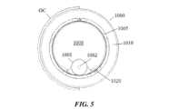
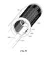
次に、図面を参照すると、閉塞または他の血管障害または血管状態を評価し及び/または治療するための医療処置の間に、1または複数のガイドワイヤおよび/または他の最小侵襲的血管内デバイスを固定または捕捉するために使用可能である、ガイドカテーテル延長部1000の形態の血管内デバイスの一例が示されている。ガイドカテーテル延長部1000は、本明細書に記載のガイドカテーテル「GC」を通過し、かつこれから遠位へ延びるようなサイズで構成されている。ガイドカテーテル延長部1000は、概して、遠位管フレーム1005へ結合される押し部材1001を含み、かつ、使用中に、ガイドカテーテル延長部1000の近位領域が(近位端または別個のガイドカテーテルのハブなどで)患者にアクセス可能であり、または患者の外側に位置合わせされ、一方で、ガイドカテーテル延長部1000の遠位領域が、患者の解剖学的構造内に位置合わせされるガイドカテーテルの端から外側へと遠位に延びるに足る長さを有してもよい。Referring now to the drawings, there is shown one example of an intravascular device in the form of a
押し部材1001は、たとえば、ハイポチューブ、スパイラルカットされたハイポチューブ、マルチスレッドケーブル、断続スパイラルカットチューブ、他のカット・ジオメトリ/形状、または他の細長い部材の1または複数のセグメントを含んでもよく、かつ内部に、及び/またはそれを通して、1または複数のワイヤ、デバイス、流体送達および/または吸引機能またはこれらに類似するものを通すための1または複数のルーメン1002を含んでもよい。The
押し部材1001は、ガイドカテーテル内部で押し部材1001が占める空間量を減らし、これにより、1または複数の他のデバイス、器具その他がガイドカテーテルを最小の妨害または閉塞で通過できるようにするために、ガイドカテーテルの内径またはクリアランスよりも小さい直径または断面プロファイルを含んでもよい。たとえば、押し部材1001は、1.1016~30.48mm(0.04~1.20インチ)の内径を有するガイドカテーテルにおいて使用するために、約0.254mm(0.010インチ)~約2.54mm(0.100インチ)の直径または断面幅を有してもよい。ある好ましい例において、押し部材1001は、約0.254mm(0.010インチ)~約0.762mm(0.030インチ)の直径または断面幅を有してもよい。押し部材1001は、その長さに沿って、円形、半円形、正方形、長方形、三角形および/または楕円形の形状またはプロファイルを含む、但しこれらに限定されない1または複数の断面形状またはプロファイルを有してもよい。さらに、及び/または代替的に、押し部材1001は、その1または複数の部分に複数のカットパターンを含むことが可能である。The
押し部材1001は、ガイドカテーテル延長部1000の長さの大部分を構成する全長を画定してもよい。押し部材1001の長さは、切開部または患者のアクセスポイント(たとえば、ハブ、止血弁およびこれらに類似するものが含まれ得る)に入り、患者の血管系を通り、かつ、押し部材1001の一部分が患者の外側に残って医師によるアクセス可能/操作可能な状態で、管フレーム1005を所望の治療部位に近接して位置合わせするに足るものであってもよい。この長さは、実行されている特定の処置もしくは用途および/または利用されている血管系アクセスポイント(たとえば、導入経路が橈骨動脈、大腿動脈、対側アクセスまたはこれらに類似するもののどれであるか)に依存して変わってもよい。ガイドカテーテル延長部1000の押し部材および/または他の近位部分は、医師が延長部1000をガイドカテーテル内に挿入し過ぎることを防止する停止機能を含んでもよい。たとえば、ガイドカテーテル延長部1000は、ガイドカテーテル延長部1000の過剰挿入を機械的に防止するために、ガイドカテーテル、止血弁および/または近位デバイスハブの直径またはサイズを超える隆起した突出部、溶接部または他の塊を含んでもよい。The
管フレーム1005は、外壁1007と、介入血管デバイスを通して受け入れるに足る直径、近位端1012および遠位端1013を有するルーメン1008を囲む内壁1006とを含み、そうでなければこれらを画定する。管フレーム1005は、内部に複数のカットパターン1015、1016を有する(但し、1015および1016は、管フレーム内に存在し得る様々なカットパターンのうちの可能な2つの実施形態を提示したものに過ぎない)。The
管フレーム1005は、ニチノールまたはステンレス鋼から構築されてもよい。たとえば、管フレームは、金属、ポリマーまたはポリマーと金属との組合せから作製されることが可能である。使用され得る材料の例としては、ステンレス鋼(SST)、ニッケルチタン(ニチノール)またはポリマーが含まれる。使用され得る他の金属の好ましい例としては、超弾性ニッケルチタン、形状記憶ニッケルチタン、Ti-Ni、ニッケルチタン、約55~60重量%Ni、Ni-Ti-Hf、Ni-Ti-Pd、Ni-Mn-Ga、300~400シリーズ、たとえば304、316、402、440シリーズにおけるSAEグレードのステンレス鋼(SST)、MP35N、および17-7析出硬化(PH)ステンレス鋼、他のばね鋼、または他の高引張強度材料、または他の生体適合性金属材料が含まれる。ある好ましい実施形態では、材料は、超弾性または形状記憶(たとえば、ニッケルチタン)であるが、別の好ましい実施形態では、材料は、ステンレス鋼である。The
管フレーム1005は、超弾性合金(概して、「形状記憶合金」と称される)をその全体に、またはその選択された部分にのみ含むことが可能である。このような超弾性合金の例には、Elgiloy(登録商標)およびPhynox(登録商標)、ばね合金、SAEグレード316ステンレス鋼およびMP35N(ニッケルコバルト)、ならびに超弾性ニチノールが含まれる。The
あるいは、管フレームは、たとえば、ポリイミド、PEEK、ナイロン、ポリウレタン、ポリエチレンテレフタレート(PET)、ラテックス、HDHMWPE(高密度高分子量ポリエチレン)、および熱可塑性エラストマ、または類似の機械的特性を有する他のポリマーを含む、ポリマーから形成されてもよい。Alternatively, the tube frame may be formed from a polymer, including, for example, polyimide, PEEK, nylon, polyurethane, polyethylene terephthalate (PET), latex, HDHMWPE (high density high molecular weight polyethylene), and thermoplastic elastomers, or other polymers with similar mechanical properties.
管フレーム1005は、超弾性金属のパイプを形成し、次に、ノッチまたは孔が形成されるべきパイプ部分を除去することによって作製されてもよい。ノッチ、孔またはカットは、レーザ(たとえば、固体フェムト秒レーザ、またはYAGレーザ)、放電(放電加工(EDM))、化学エッチング、フォトエッチング、機械的切断、またはこれらの技術のいずれかの組合せ使用により、パイプ内に形成されることが可能である。The
管フレーム1005の一部分は、ポリマーライナを有することができ、及び/または、管フレーム1005の外壁は、外部ジャケットで(完全に、部分的に、及び/または断続的に)覆われることが可能である。A portion of the
管フレーム1005は、管フレーム1005の近位端1012から延びるタングエレメント1017を有し、かつタングエレメント1017は、押し部材1001へ結合される。タングエレメント1017は、管フレーム1005と一体であってもよく、かつ管フレーム1005と同じ材料組成物から形成されてもよい。タングエレメント1017の遠位端または遠位領域は、管フレーム1005の近位開口より遠位に位置合わせされてもよく、一方で、タングエレメント1017の近位端または近位領域は、管フレーム1005の近位開口を越えて近位へ延在する。The
管フレーム1005の近位端1012は、管フレーム1005とガイドカテーテルGCとの間の間隙を閉鎖または縮小するために使用可能なフレアまたはフランジ1019を含んでもよい。The
押し部材1001、遠位管フレーム1005および他のコンポーネントを含むガイドカテーテル延長部1000の追加的な特徴および特性は、「GUIDE CATHETER EXTENSION PLATFORM」と題する米国特許出願第62/729,282号明細書に記載されていて、該特許出願は、その全体が参照により開示に含まれる。Additional features and characteristics of the
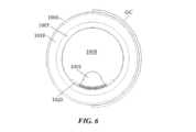
ガイドカテーテル延長部1000は、遠位管フレームのルーメン1008内に位置合わせされる1または複数の膨張性エレメント1020を含んでもよい。(1または複数の)膨張性エレメント1020は、1または複数のバルーン、ブラダ、または、内部に流体が導入された時点で拡張可能な他のコンポーネントを含んでもよい。膨張性エレメントは、様々な形状で形成されてもよく、かつ対称性、非対称性または他の輪郭取りされた、または幾何学的形状を含んでもよい。(1または複数の)膨張性エレメント1020は、たとえばシリコーン、ナイロン、ペバックスおよび/または他のポリマーから構築され得る、コンプライアントな、および/または非コンプライアントな表面および/またはコンポーネントを含んでもよい。The
図1~図6に示す例において、膨張性エレメント1020は、内壁1006の上またはその周りに管フレーム1005の遠位端1013へ向かって配置される。膨張性エレメント1020は、遠位管フレーム1005のルーメン1008内で拡張するように位置づけられ、かつそのように動作可能である。したがって、膨張性エレメント1020は、遠位管フレームの内壁1006上へ接着されても、該内壁1006上へ別段で直に位置合わせされてもよい。In the example shown in FIGS. 1-6, the
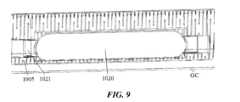
図7~図12に示す例において、膨張性エレメント1020は、内壁1006の上またはその周りに管フレーム1005の遠位端1013へ向かって配置され、かつ、膨張性エレメント1020は、遠位管フレーム1005のルーメン1008内、およびガイドカテーテル延長部1000とこれを囲む外部ガイドカテーテルGCとの間の空間内への双方で拡張するように位置づけられ、かつそのように動作可能である。このような拡張特性に対応するために、遠位管フレーム1005の壁の一部分は、膨張性エレメント1020がルーメン1008内で、およびガイドカテーテルGC方向への内外双方に拡張することを可能にする窓または空間を形成するようにカットされてもよい。7-12, the
膨張性エレメント1020は、ルーメン1008内へ、および管フレーム1005の直径または外壁の外側からガイドカテーテル延長部1000とガイドカテーテルGCとの間の空間内への双方に拡張するための、単一の内部空洞を含んでもよい。ある代替例において、膨張性エレメント1020は、ルーメン1008内へと拡張する膨張性エレメント1020の部分が、管フレーム1005の直径または外壁の外側で拡張する膨張性エレメント1020の部分とは独立してかつ別個に制御されて膨張可能であるように、独立して膨張可能な複数の内部空洞および/またはリザーバを含んでもよい。膨張性エレメント1020の別個の部分は、独立した動作を提供するために独立した膨張ルーメンを有してもよい。別の例では、ルーメン1008内および管フレーム1005の外側に独立した膨張を提供するために、複数の別個の膨張性エレメントが使用されてもよい。The
使用時、膨張性エレメント1020は、膨張性エレメントが略平坦、平ら及び/またはその他膨張していない第1の状態から、膨張性エレメント1020が膨張されて、遠位管フレームのルーメン1008の直径の、ルーメン1008を通って進むどのデバイスの断面積よりは少ないかなりの部分を占めるように拡大する第2の状態へと移行可能であってもよい。たとえば、膨張された膨張性エレメントは、ルーメン1008の断面積の約10%~約90%を占有する拡張能力を提供してもよい。ある特定の処置に必要とされる特定の拡張は、医師がルーメン1008内に閉じ込める、または固定しようとする補助デバイスの数およびサイズに依存して変わり得る。直径が比較的小さい単一のデバイスが固定される場合には、膨張性エレメント1020のより大きい拡張が使用され得る。対照的に、ルーメン1008内に大きい断面積を有する複数のデバイスを固定するには、膨張性エレメント1020のより少量の膨張が必要とされる。膨張性エレメント1020の拡張および/または適合性は、ルーメン1008内に固定されるデバイスの可変サイズに対応すべく、膨張性エレメント1020の長手方向長さに沿って変わってもよい(たとえば、捕捉されるデバイスのうちの1つまたはそれ以上が、その長さに沿って変わる断面または外形寸法を有する場合)。In use, the
膨張性エレメント1020の一部分がガイドカテーテルGCとガイドカテーテル延長部1000との間の空間内へと外向きに拡張する一例では、膨張性エレメント1020は、本明細書で詳述するように、ガイドカテーテルGCとガイドカテーテル延長部1000との間の断面空間を略塞ぐように拡張されてもよい。In one example where a portion of the
膨張性エレメント1020は、押し部材1001のルーメン1002と流体連通していて、これは、膨張媒体(たとえば、空気、生理食塩水、蒸留水またはその他)を膨張性エレメント1020内へ導入するためのチャネルとして使用されてもよい。膨張性エレメント1020は、押し部材1001へ直に結合されてもよく、あるいは、遠位管フレーム1005の一部分を通って延在しかつ外側へ延在して近位方向に押し部材1001へ接続し、同時に遠位方向に膨張性エレメント1020とも結合する中間膨張スパウトまたはチャネル1021を介して押し部材1001に結合してもよい。図示の例において、中間膨張チャネル1021は、ルーメン1008の動作直径および結果的に他のデバイスまたは器具を通過させる能力を略妨害する、または低減させることを回避するために、低い断面プロファイルおよびルーメン1008のそれと相補的な曲率を有する。管フレーム1005の壁厚の一部分は、中間膨張スパウトまたはチャネル1021をさらに収容しかつルーメン1008の動作直径を略妨害する、または低減させることをさらに回避するために、溝を形成すべく縮小されてもよい。The
(1または複数の)膨張性エレメント1020は、その中に流体を導入することによって拡張されてもよく、該流体は、ガイドカテーテル延長部1000上の近位ハブまたは注入ポート(不図示)に提供されてもよい。膨張性エレメント1020の制御可能な拡張は、ポンプ、シリンジ、媒体カートリッジ、または血管手術で使用される他の流体導入機構によって促進されてもよく、かつ1または複数のセンサ、医療撮像モダリティまたはこれらに類似するものを介して監視されてもよい。The inflatable element(s) 1020 may be expanded by introducing fluid therein, which may be provided to a proximal hub or injection port (not shown) on the
ある使用例において、ガイドカテーテル延長部1000は、患者の血管系内で1または複数の補助デバイスを捕捉して固定するために使用されてもよい。たとえば、CTOを治療する場合、所定の技術は、複数のデバイスを用いて、順行性方向および逆行性方向の両方からCTOへ接近する。CART技術では、ガイドワイヤが順行性にCTO病変へと方向づけられ、同時に、逆行性のバルーンデバイスが亀裂または開口を作るべくCTO病変内へ前進される。逆CART技術では、ガイドワイヤが病変の遠位から逆行性に接近する間に、CTO病変の近位部で順行性バルーンにより内膜下亀裂の生成が実行される。これらの技術、またはCTOもしくは他の生理学的状態/領域およびその周辺で複数のデバイスが関与する他の処置のいずれにおいても、ガイドカテーテル延長部1000は、標的とされる(1または複数の)補助デバイスの遠位端を固定するために使用されてもよく、ガイドカテーテル延長部1000は、CART技術において逆行性バルーンデバイスを、及び/または逆CART技術において逆行性ガイドワイヤを含んでもよい。他の状況では、CTOの順行性領域および/または逆行性領域において、1または複数のデバイス部分を捕捉することが望ましい場合がある。In some use cases, the
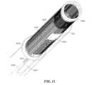
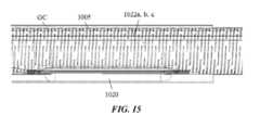
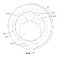
図13~図18は、複数の補助デバイス1022a、1022b、1022c(集合的に、「補助デバイス1022」)が少なくとも部分的に遠位管フレーム1005の内部ルーメン1008内に位置合わせされ、かつ拡張された膨張性エレメント1020によって定位置に固定される類の使用例を示す。図示の例は、遠位管フレーム1005を貫通して延びる補助デバイス1022を示しているが、遠位管フレームに対する順行性および/または逆行性補助デバイス1022の長さおよびポジションは、これらのデバイスをルーメン1008内に固定するに足る重なりが補助デバイス1022と膨張性エレメント1020との間に存在する限り、変わってもよい。膨張性エレメント1020が遠位管フレーム1005の外部へ、および外部ガイドカテーテルGCとガイドカテーテル延長部1000との間の空間内へと拡張する実施形態において、膨張性エレメント1020の拡張は、ルーメン1008内での補助デバイス1022の相対的位置合わせ、ならびにガイドカテーテルGC内でのガイドカテーテル延長部1000の相対的位置合わせを確実にすることの双方を保証する。13-18 show an example of such a use in which multiple
膨張性エレメント1020の比較的遠位のロケーションは、医師がルーメン1008内のデバイスを、ガイドカテーテル延長部1000に進入するために必要な補助デバイス1022の長さを最小限に及び/または短くして捕捉することを可能にし、かつ、補助デバイス1022を外部ガイドカテーテルGC自体へとさらに近位へ取り込む必要性を排除する。これにより、補助デバイスをGC内に取り込んで閉じ込めることのある他のデバイスに比べて、補助デバイス1022を固定するために医師が必要とする操縦およびナビゲーションが低減される。The relatively distal location of the
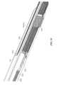
別の例において、デバイス1000は、図19~図20に示すように、押し部材1001上に位置合わせされる膨張性エレメント1020を含んでもよい。デバイスのこの例1000は、固定用のロケーションが管フレーム1005の内側ではなく管フレーム1005の近位にある状態で、1または複数の補助デバイス1022を上記と同様にして固定するために使用され得る。図示の例において、膨張性エレメント1020は、それが押し部材1001の長手方向軸の長さに沿って近位方向および遠位方向に移動可能であるように、押し部材1001へ摺動可能に搭載または結合されてもよい。たとえば、膨張性エレメント1020は、摺動可能な動きを提供するために、押し部材1001上へ同軸的及び/または同心的に取り付けられるシャフト1030へ付着されてもよい。シャフト1030は、その長さに沿って1または複数の長さの可変チューブを含んでもよく、かつ膨張性エレメント1020の1または複数の部分は、1または複数の接合部においてシャフト1030へ付着されてもよい。シャフトは、その内部に1または複数の膨張ルーメン1032を含んでも、画定してもよい。(1または複数の)ルーメン1032は、シャフト1030の内径の1または複数のセグメント、シャフト1030内に位置合わせされる1または複数のチューブ、および/または、膨張性エレメント1020の内部への流体経路を提供する、シャフト1030と押し部材1001との間の1または複数の空間を含んでもよい。(1または複数の)膨張ルーメン1032は、本明細書で記述しているように、デバイス1000の近位端またはハブで膨張源へ付着されてもよい。In another example, the
本開示が、本明細書においてこれまでに具体的に示されかつ説明されたものに限定されないことは、当業者に理解されるであろう。さらに、これまでに反対のことが言及されていない限り、添付の図面が全て縮尺通りでないことは、留意されるべきである。なお、システムコンポーネントは、本明細書における記載を利用できる一般的な当業者には容易に明らかとなる詳細で本開示を不明瞭にしないように、適宜、本開示の実施形態の理解に関連のある特定の詳細のみを示す図中の従来の記号によって表されている。さらに、本明細書に記述している所定の実施形態または図は、他の図または実施形態に明示的に示されていない特徴を示すことがあるが、本明細書に開示している例の特徴およびコンポーネントが必ずしも互いに排他的なものではなく、よって、本開示の範囲および精神を逸脱することなく、様々な異なる組合せまたは構成において包含され得ることは、理解される。上述の教示に鑑みれば、添付の特許請求の範囲によってのみ限定される本開示の範囲および精神を逸脱することなく、様々な変更および変形が可能である。It will be understood by those skilled in the art that the present disclosure is not limited to what has been specifically shown and described hereinbefore. Moreover, unless previously noted to the contrary, it should be noted that all of the accompanying drawings are not to scale. It should be noted that system components are represented by conventional symbols in the figures that, where appropriate, show only certain details relevant to understanding the embodiments of the present disclosure, so as not to obscure the present disclosure with details that will be readily apparent to one of ordinary skill in the art having the benefit of the description herein. Moreover, while a given embodiment or figure described herein may show features that are not explicitly shown in other figures or embodiments, it is understood that the features and components of the examples disclosed herein are not necessarily mutually exclusive, and thus may be included in various different combinations or configurations without departing from the scope and spirit of the present disclosure. In light of the above teachings, various modifications and variations are possible without departing from the scope and spirit of the present disclosure, which is limited only by the scope of the appended claims.
Claims (6)
Translated fromJapanese前記押し部材の遠位端へ結合される管フレームであって、該管フレームを通して介入血管デバイスを受け入れるに足る直径を有するルーメンを画定する、管フレームと、
前記管フレームへ結合される膨張性エレメントであって、前記ルーメン内へと拡張可能である、膨張性エレメントと
を備え、
前記膨張性エレメントは、前記管フレームの外面を越えて外側へ拡張可能である、ガイドカテーテル延長部。 a pusher member having a proximal end and a distal end;
a tube frame coupled to a distal end of the pusher member, the tube frame defining a lumen having a diameter sufficient to receive an interventional vascular device therethrough;
an expandable element coupled to the tube frame, the expandable element being expandable into the lumen;
The expandable element is expandable outwardly beyond an outer surface of the tubular frame, a guide catheter extension.
前記タングエレメントは、前記押し部材の遠位領域へ直結される、請求項1に記載のガイドカテーテル延長部。 a tang element extending from a proximal segment of the tube frame;
The guide catheter extension of claim 1 , wherein the tang element is directly connected to a distal region of the pusher member.
Priority Applications (1)
| Application Number | Priority Date | Filing Date | Title |
|---|---|---|---|
| JP2024150686AJP2024164267A (en) | 2019-06-24 | 2024-09-02 | Balloon fixation guide catheter extension |
Applications Claiming Priority (3)
| Application Number | Priority Date | Filing Date | Title |
|---|---|---|---|
| US201962865498P | 2019-06-24 | 2019-06-24 | |
| US62/865,498 | 2019-06-24 | ||
| PCT/US2020/039086WO2020263798A1 (en) | 2019-06-24 | 2020-06-23 | Balloon anchoring guide catheter extension |
Related Child Applications (1)
| Application Number | Title | Priority Date | Filing Date |
|---|---|---|---|
| JP2024150686ADivisionJP2024164267A (en) | 2019-06-24 | 2024-09-02 | Balloon fixation guide catheter extension |
Publications (2)
| Publication Number | Publication Date |
|---|---|
| JP2022540763A JP2022540763A (en) | 2022-09-20 |
| JP7621990B2true JP7621990B2 (en) | 2025-01-27 |
Family
ID=71143579
Family Applications (2)
| Application Number | Title | Priority Date | Filing Date |
|---|---|---|---|
| JP2021576460AActiveJP7621990B2 (en) | 2019-06-24 | 2020-06-23 | Balloon fixation guide catheter extension |
| JP2024150686APendingJP2024164267A (en) | 2019-06-24 | 2024-09-02 | Balloon fixation guide catheter extension |
Family Applications After (1)
| Application Number | Title | Priority Date | Filing Date |
|---|---|---|---|
| JP2024150686APendingJP2024164267A (en) | 2019-06-24 | 2024-09-02 | Balloon fixation guide catheter extension |
Country Status (5)
| Country | Link |
|---|---|
| US (3) | US11524144B2 (en) |
| EP (1) | EP3756722A1 (en) |
| JP (2) | JP7621990B2 (en) |
| CN (2) | CN114025824B (en) |
| WO (1) | WO2020263798A1 (en) |
Families Citing this family (1)
| Publication number | Priority date | Publication date | Assignee | Title |
|---|---|---|---|---|
| US11660420B2 (en) | 2018-09-17 | 2023-05-30 | Seigla Medical, Inc. | Catheters and related devices and methods of manufacture |
Citations (4)
| Publication number | Priority date | Publication date | Assignee | Title |
|---|---|---|---|---|
| JP2003529438A (en) | 2000-04-07 | 2003-10-07 | カイフォン インコーポレイテッド | Insertion device and its use |
| US20160175569A1 (en) | 2014-12-22 | 2016-06-23 | Richard R. Heuser | Device for treating vascular occlusion |
| US20170252043A1 (en) | 2016-03-03 | 2017-09-07 | Boston Scientific Scimed, Inc. | Guide extension catheter with expandable balloon |
| JP2018508281A (en) | 2015-05-26 | 2018-03-29 | テレフレックス イノベーションズ エス.アー.エール.エル. | Guide wire fixing |
Family Cites Families (15)
| Publication number | Priority date | Publication date | Assignee | Title |
|---|---|---|---|---|
| US5792118A (en) | 1994-03-07 | 1998-08-11 | Kurth; Paul A. | Permanent catheter with an exterior balloon valve and method of using the same |
| US5820595A (en)* | 1995-06-07 | 1998-10-13 | Parodi; Juan C. | Adjustable inflatable catheter and method for adjusting the relative position of multiple inflatable portions of a catheter within a body passageway |
| ATE327797T1 (en)* | 1996-04-26 | 2006-06-15 | Schneider Europ Gmbh | INTERVENTION CATHETER |
| US6123712A (en)* | 1996-08-23 | 2000-09-26 | Scimed Life Systems, Inc. | Balloon catheter with stent securement means |
| US6135981A (en)* | 1997-10-22 | 2000-10-24 | Dyke; Charles C. | Protective aortic occlusion catheter |
| US7815649B2 (en)* | 2000-04-07 | 2010-10-19 | Kyphon SÀRL | Insertion devices and method of use |
| CN104812420B (en)* | 2012-08-17 | 2017-09-22 | 波士顿科学西美德公司 | Guiding extension conduit |
| EP2961458B1 (en) | 2013-03-01 | 2018-01-10 | Boston Scientific Scimed, Inc. | Guide extension catheter with a retractable wire |
| US10792056B2 (en) | 2014-06-13 | 2020-10-06 | Neuravi Limited | Devices and methods for removal of acute blockages from blood vessels |
| US10668254B2 (en) | 2014-08-25 | 2020-06-02 | Radius Medical LLC | Stabilizing and sealing catheter for use with a guiding catheter |
| JP6749847B2 (en)* | 2015-01-26 | 2020-09-02 | テルモ株式会社 | Balloon catheter |
| WO2017019900A1 (en)* | 2015-07-28 | 2017-02-02 | Andrew Ho, M.D., Inc. | Guide catheter extension device and methods of use for cardiology procedures |
| ES2987464T3 (en) | 2016-08-10 | 2024-11-14 | Nipro Corp | Support catheter |
| CN208852082U (en)* | 2017-11-16 | 2019-05-14 | 遵义医学院附属医院 | A balloon-fixed biliary drainage device |
| CN214286263U (en)* | 2020-06-23 | 2021-09-28 | 祥丰医疗私人有限公司 | Guide catheter extension |
- 2020
- 2020-06-23CNCN202080046272.9Apatent/CN114025824B/enactiveActive
- 2020-06-23WOPCT/US2020/039086patent/WO2020263798A1/ennot_activeCeased
- 2020-06-23JPJP2021576460Apatent/JP7621990B2/enactiveActive
- 2020-06-23USUS16/909,320patent/US11524144B2/enactiveActive
- 2020-06-23CNCN202411312747.0Apatent/CN118949240A/enactivePending
- 2020-06-24EPEP20182056.0Apatent/EP3756722A1/enactivePending
- 2022
- 2022-11-07USUS17/982,008patent/US12083293B2/enactiveActive
- 2024
- 2024-08-02USUS18/793,046patent/US20240390651A1/enactivePending
- 2024-09-02JPJP2024150686Apatent/JP2024164267A/enactivePending
Patent Citations (4)
| Publication number | Priority date | Publication date | Assignee | Title |
|---|---|---|---|---|
| JP2003529438A (en) | 2000-04-07 | 2003-10-07 | カイフォン インコーポレイテッド | Insertion device and its use |
| US20160175569A1 (en) | 2014-12-22 | 2016-06-23 | Richard R. Heuser | Device for treating vascular occlusion |
| JP2018508281A (en) | 2015-05-26 | 2018-03-29 | テレフレックス イノベーションズ エス.アー.エール.エル. | Guide wire fixing |
| US20170252043A1 (en) | 2016-03-03 | 2017-09-07 | Boston Scientific Scimed, Inc. | Guide extension catheter with expandable balloon |
Also Published As
| Publication number | Publication date |
|---|---|
| EP3756722A1 (en) | 2020-12-30 |
| US20200398028A1 (en) | 2020-12-24 |
| JP2022540763A (en) | 2022-09-20 |
| JP2024164267A (en) | 2024-11-26 |
| CN114025824B (en) | 2024-10-15 |
| US12083293B2 (en) | 2024-09-10 |
| US20240390651A1 (en) | 2024-11-28 |
| US11524144B2 (en) | 2022-12-13 |
| US20230061282A1 (en) | 2023-03-02 |
| CN114025824A (en) | 2022-02-08 |
| CN118949240A (en) | 2024-11-15 |
| WO2020263798A1 (en) | 2020-12-30 |
Similar Documents
| Publication | Publication Date | Title |
|---|---|---|
| JP7659579B2 (en) | Intravascular delivery system and method for percutaneous coronary intervention - Patents.com | |
| CN108136159B (en) | Occlusion Bypass Device with Reentry Needle and Distal Stabilizing Balloon | |
| JP4869236B2 (en) | Catheter system for protective angioplasty and stenting at the carotid bifurcation | |
| US6152909A (en) | Aspiration system and method | |
| US7371248B2 (en) | Steerable distal protection guidewire and methods of use | |
| US20020035347A1 (en) | Aspiration catheter | |
| US20020177800A1 (en) | Aspiration catheters and method of use | |
| JP2012513294A (en) | System and method for removing occlusive material from body cavities and treating vascular disorders | |
| JP2011516183A (en) | Multi-effect microcatheter system and method of use | |
| GB2397530A (en) | Guideware apparatus for temporary distal embolic protection | |
| US11779362B1 (en) | Methods and apparatus for true lumen re-entry | |
| US20060282113A1 (en) | Mechanically expandable distal protection apparatus and method of use | |
| US20230355255A1 (en) | Methods and devices for treating vascular disease | |
| JP2024164267A (en) | Balloon fixation guide catheter extension | |
| JP7648029B2 (en) | Isolated endovascular procedures with perfusion bypass | |
| CN214286263U (en) | Guide catheter extension | |
| US20240374878A1 (en) | Scraper Balloon Catheter Device | |
| US20240016633A1 (en) | Devices for accessing and treating venous sinuses and methods of use | |
| HK40043761A (en) | Balloon anchoring guide catheter extension | |
| JP2025534726A (en) | Intravascular delivery system and method for percutaneous coronary intervention including perfusion - Patent Application 20070122997 | |
| JP2007007021A (en) | Catheter | |
| JP2007202614A (en) | Catheter |
Legal Events
| Date | Code | Title | Description |
|---|---|---|---|
| A621 | Written request for application examination | Free format text:JAPANESE INTERMEDIATE CODE: A621 Effective date:20230620 | |
| A977 | Report on retrieval | Free format text:JAPANESE INTERMEDIATE CODE: A971007 Effective date:20240510 | |
| A131 | Notification of reasons for refusal | Free format text:JAPANESE INTERMEDIATE CODE: A131 Effective date:20240604 | |
| A521 | Request for written amendment filed | Free format text:JAPANESE INTERMEDIATE CODE: A523 Effective date:20240902 | |
| TRDD | Decision of grant or rejection written | ||
| A01 | Written decision to grant a patent or to grant a registration (utility model) | Free format text:JAPANESE INTERMEDIATE CODE: A01 Effective date:20241224 | |
| A61 | First payment of annual fees (during grant procedure) | Free format text:JAPANESE INTERMEDIATE CODE: A61 Effective date:20250115 | |
| R150 | Certificate of patent or registration of utility model | Ref document number:7621990 Country of ref document:JP Free format text:JAPANESE INTERMEDIATE CODE: R150 |