JP7621959B2 - Double Heart Valve Tethering - Google Patents
Double Heart Valve TetheringDownload PDFInfo
- Publication number
- JP7621959B2 JP7621959B2JP2021550041AJP2021550041AJP7621959B2JP 7621959 B2JP7621959 B2JP 7621959B2JP 2021550041 AJP2021550041 AJP 2021550041AJP 2021550041 AJP2021550041 AJP 2021550041AJP 7621959 B2JP7621959 B2JP 7621959B2
- Authority
- JP
- Japan
- Prior art keywords
- coupler
- valve replacement
- tricuspid
- mitral valve
- anchoring
- Prior art date
- Legal status (The legal status is an assumption and is not a legal conclusion. Google has not performed a legal analysis and makes no representation as to the accuracy of the status listed.)
- Active
Links
Images


Classifications
- A—HUMAN NECESSITIES
- A61—MEDICAL OR VETERINARY SCIENCE; HYGIENE
- A61F—FILTERS IMPLANTABLE INTO BLOOD VESSELS; PROSTHESES; DEVICES PROVIDING PATENCY TO, OR PREVENTING COLLAPSING OF, TUBULAR STRUCTURES OF THE BODY, e.g. STENTS; ORTHOPAEDIC, NURSING OR CONTRACEPTIVE DEVICES; FOMENTATION; TREATMENT OR PROTECTION OF EYES OR EARS; BANDAGES, DRESSINGS OR ABSORBENT PADS; FIRST-AID KITS
- A61F2/00—Filters implantable into blood vessels; Prostheses, i.e. artificial substitutes or replacements for parts of the body; Appliances for connecting them with the body; Devices providing patency to, or preventing collapsing of, tubular structures of the body, e.g. stents
- A61F2/02—Prostheses implantable into the body
- A61F2/24—Heart valves ; Vascular valves, e.g. venous valves; Heart implants, e.g. passive devices for improving the function of the native valve or the heart muscle; Transmyocardial revascularisation [TMR] devices; Valves implantable in the body
- A61F2/2412—Heart valves ; Vascular valves, e.g. venous valves; Heart implants, e.g. passive devices for improving the function of the native valve or the heart muscle; Transmyocardial revascularisation [TMR] devices; Valves implantable in the body with soft flexible valve members, e.g. tissue valves shaped like natural valves
- A61F2/2418—Scaffolds therefor, e.g. support stents
- A—HUMAN NECESSITIES
- A61—MEDICAL OR VETERINARY SCIENCE; HYGIENE
- A61F—FILTERS IMPLANTABLE INTO BLOOD VESSELS; PROSTHESES; DEVICES PROVIDING PATENCY TO, OR PREVENTING COLLAPSING OF, TUBULAR STRUCTURES OF THE BODY, e.g. STENTS; ORTHOPAEDIC, NURSING OR CONTRACEPTIVE DEVICES; FOMENTATION; TREATMENT OR PROTECTION OF EYES OR EARS; BANDAGES, DRESSINGS OR ABSORBENT PADS; FIRST-AID KITS
- A61F2/00—Filters implantable into blood vessels; Prostheses, i.e. artificial substitutes or replacements for parts of the body; Appliances for connecting them with the body; Devices providing patency to, or preventing collapsing of, tubular structures of the body, e.g. stents
- A61F2/02—Prostheses implantable into the body
- A61F2/24—Heart valves ; Vascular valves, e.g. venous valves; Heart implants, e.g. passive devices for improving the function of the native valve or the heart muscle; Transmyocardial revascularisation [TMR] devices; Valves implantable in the body
- A—HUMAN NECESSITIES
- A61—MEDICAL OR VETERINARY SCIENCE; HYGIENE
- A61F—FILTERS IMPLANTABLE INTO BLOOD VESSELS; PROSTHESES; DEVICES PROVIDING PATENCY TO, OR PREVENTING COLLAPSING OF, TUBULAR STRUCTURES OF THE BODY, e.g. STENTS; ORTHOPAEDIC, NURSING OR CONTRACEPTIVE DEVICES; FOMENTATION; TREATMENT OR PROTECTION OF EYES OR EARS; BANDAGES, DRESSINGS OR ABSORBENT PADS; FIRST-AID KITS
- A61F2220/00—Fixations or connections for prostheses classified in groups A61F2/00 - A61F2/26 or A61F2/82 or A61F9/00 or A61F11/00 or subgroups thereof
- A61F2220/0008—Fixation appliances for connecting prostheses to the body
- A—HUMAN NECESSITIES
- A61—MEDICAL OR VETERINARY SCIENCE; HYGIENE
- A61F—FILTERS IMPLANTABLE INTO BLOOD VESSELS; PROSTHESES; DEVICES PROVIDING PATENCY TO, OR PREVENTING COLLAPSING OF, TUBULAR STRUCTURES OF THE BODY, e.g. STENTS; ORTHOPAEDIC, NURSING OR CONTRACEPTIVE DEVICES; FOMENTATION; TREATMENT OR PROTECTION OF EYES OR EARS; BANDAGES, DRESSINGS OR ABSORBENT PADS; FIRST-AID KITS
- A61F2220/00—Fixations or connections for prostheses classified in groups A61F2/00 - A61F2/26 or A61F2/82 or A61F9/00 or A61F11/00 or subgroups thereof
- A61F2220/0025—Connections or couplings between prosthetic parts, e.g. between modular parts; Connecting elements
- A61F2220/0075—Connections or couplings between prosthetic parts, e.g. between modular parts; Connecting elements sutured, ligatured or stitched, retained or tied with a rope, string, thread, wire or cable
- A—HUMAN NECESSITIES
- A61—MEDICAL OR VETERINARY SCIENCE; HYGIENE
- A61F—FILTERS IMPLANTABLE INTO BLOOD VESSELS; PROSTHESES; DEVICES PROVIDING PATENCY TO, OR PREVENTING COLLAPSING OF, TUBULAR STRUCTURES OF THE BODY, e.g. STENTS; ORTHOPAEDIC, NURSING OR CONTRACEPTIVE DEVICES; FOMENTATION; TREATMENT OR PROTECTION OF EYES OR EARS; BANDAGES, DRESSINGS OR ABSORBENT PADS; FIRST-AID KITS
- A61F2230/00—Geometry of prostheses classified in groups A61F2/00 - A61F2/26 or A61F2/82 or A61F9/00 or A61F11/00 or subgroups thereof
- A61F2230/0002—Two-dimensional shapes, e.g. cross-sections
- A61F2230/0028—Shapes in the form of latin or greek characters
- A61F2230/0054—V-shaped
- A—HUMAN NECESSITIES
- A61—MEDICAL OR VETERINARY SCIENCE; HYGIENE
- A61F—FILTERS IMPLANTABLE INTO BLOOD VESSELS; PROSTHESES; DEVICES PROVIDING PATENCY TO, OR PREVENTING COLLAPSING OF, TUBULAR STRUCTURES OF THE BODY, e.g. STENTS; ORTHOPAEDIC, NURSING OR CONTRACEPTIVE DEVICES; FOMENTATION; TREATMENT OR PROTECTION OF EYES OR EARS; BANDAGES, DRESSINGS OR ABSORBENT PADS; FIRST-AID KITS
- A61F2250/00—Special features of prostheses classified in groups A61F2/00 - A61F2/26 or A61F2/82 or A61F9/00 or A61F11/00 or subgroups thereof
- A61F2250/0004—Special features of prostheses classified in groups A61F2/00 - A61F2/26 or A61F2/82 or A61F9/00 or A61F11/00 or subgroups thereof adjustable
- A61F2250/0007—Special features of prostheses classified in groups A61F2/00 - A61F2/26 or A61F2/82 or A61F9/00 or A61F11/00 or subgroups thereof adjustable for adjusting length
- A—HUMAN NECESSITIES
- A61—MEDICAL OR VETERINARY SCIENCE; HYGIENE
- A61F—FILTERS IMPLANTABLE INTO BLOOD VESSELS; PROSTHESES; DEVICES PROVIDING PATENCY TO, OR PREVENTING COLLAPSING OF, TUBULAR STRUCTURES OF THE BODY, e.g. STENTS; ORTHOPAEDIC, NURSING OR CONTRACEPTIVE DEVICES; FOMENTATION; TREATMENT OR PROTECTION OF EYES OR EARS; BANDAGES, DRESSINGS OR ABSORBENT PADS; FIRST-AID KITS
- A61F2250/00—Special features of prostheses classified in groups A61F2/00 - A61F2/26 or A61F2/82 or A61F9/00 or A61F11/00 or subgroups thereof
- A61F2250/0058—Additional features; Implant or prostheses properties not otherwise provided for
- A61F2250/006—Additional features; Implant or prostheses properties not otherwise provided for modular
Landscapes
- Health & Medical Sciences (AREA)
- Cardiology (AREA)
- Engineering & Computer Science (AREA)
- Biomedical Technology (AREA)
- Heart & Thoracic Surgery (AREA)
- Transplantation (AREA)
- Oral & Maxillofacial Surgery (AREA)
- Vascular Medicine (AREA)
- Life Sciences & Earth Sciences (AREA)
- Animal Behavior & Ethology (AREA)
- General Health & Medical Sciences (AREA)
- Public Health (AREA)
- Veterinary Medicine (AREA)
- Prostheses (AREA)
Description
Translated fromJapanese本出願と共に提出されている出願データシートにおいて外国または国内の優先権主張が特定されている任意およびすべての出願は、37 CFR 1.57の下で本明細書によって参照により組み込まれている。本出願は、2019年2月27日に出願されたDOUBLE HEART VALVE ANCHORINGという名称の米国仮特許出願第62/811,453号への優先権を主張し、その開示は全体において本明細書において参照により組み込まれている。Any and all applications for which a foreign or domestic priority claim is identified in an Application Data Sheet filed with this application are hereby incorporated by reference under 37 CFR 1.57. This application claims priority to U.S. Provisional Patent Application No. 62/811,453, entitled DOUBLE HEART VALVE ANCHORING, filed February 27, 2019, the disclosure of which is incorporated by reference herein in its entirety.
本開示は、概して医療埋込装置の分野に関する。This disclosure relates generally to the field of medical implant devices.
心臓弁装置の埋込みが、様々な心臓弁の異常に対処するために実施され得る。三尖弁装置と僧帽弁装置との両方の埋込みは、両方の弁において機能障害を患う患者にとって有利であり得る。Heart valve device implantation may be performed to address a variety of heart valve abnormalities. Implantation of both the tricuspid and mitral valve devices may be beneficial for patients suffering from dysfunction in both valves.
本明細書に記載されているのは、三尖弁装置と僧帽弁装置との両方を中隔に係留するための1つまたは複数の方法および/または装置である。一部の実施では、本開示は、心室中隔における第1の中隔横断開口の中に固定されるように構成される少なくとも一部分を備える第1の係留部と、第1の係留部に結合される三尖弁装置と、第1の係留部に結合される僧帽弁装置とを備える二重心臓弁係留システムに関する。Described herein are one or more methods and/or devices for anchoring both a tricuspid valve device and a mitral valve device to the septum. In some implementations, the disclosure relates to a dual heart valve anchoring system comprising a first anchoring portion having at least a portion configured to be secured within a first transseptal opening in the interventricular septum, a tricuspid valve device coupled to the first anchoring portion, and a mitral valve device coupled to the first anchoring portion.
一部の実施形態では、三尖弁装置は三尖弁置換部を備え、僧帽弁装置は僧帽弁置換部を備える。第1の連結器は、三尖弁置換部と僧帽弁置換部との間で延びることができ、三尖弁置換部および僧帽弁置換部を第1の係留部に結合し、第1の中隔横断開口を通じて延びるように構成される。In some embodiments, the tricuspid valve apparatus includes a tricuspid valve replacement portion and the mitral valve apparatus includes a mitral valve replacement portion. The first connector can extend between the tricuspid valve replacement portion and the mitral valve replacement portion and is configured to couple the tricuspid valve replacement portion and the mitral valve replacement portion to the first anchor portion and extend through the first transseptal opening.
一部の実施形態では、二重心臓弁係留システムは、三尖弁置換部と僧帽弁置換部との間で延び、三尖弁置換部と僧帽弁置換部とを結合する第2の連結器を備え得る。第1の連結器と第2の連結器との両方が、三尖弁置換部および僧帽弁置換部を第1の係留部に結合でき、第1の連結器と第2の連結器との両方は第1の中隔横断開口を通じて延びるように構成され得る。In some embodiments, the dual heart valve anchoring system may include a second connector extending between and coupling the tricuspid valve replacement portion and the mitral valve replacement portion. Both the first connector and the second connector may couple the tricuspid valve replacement portion and the mitral valve replacement portion to the first anchoring portion, and both the first connector and the second connector may be configured to extend through the first transseptal opening.
一部の実施形態では、二重心臓弁係留システムは、心室中隔における第2の中隔横断開口の中に固定されるように構成される一部分を少なくとも備える第2の係留部を備えることができ、第2の連結器は三尖弁置換部および僧帽弁置換部を第2の係留部に結合し、第2の連結器は第2の中隔横断開口を通じて延びるように構成される。In some embodiments, the dual heart valve anchoring system can include a second anchoring portion having at least a portion configured to be secured within a second transseptal opening in the ventricular septum, and a second connector couples the tricuspid valve replacement portion and the mitral valve replacement portion to the second anchoring portion, the second connector configured to extend through the second transseptal opening.
第1の連結器および第2の連結器の少なくとも一方のそれぞれの端が、右心室の中に位置決めされるように構成される三尖弁置換部の一部分と、左心室の中に位置決めされるように構成される僧帽弁置換部の一部分とに結合され得る。一部の実施形態では、第1の連結器および第2の連結器の少なくとも一方のそれぞれの端が、右心室の中に位置決めされるように構成される三尖弁置換部の遠位端と、左心室の中に位置決めされるように構成される僧帽弁置換部の遠位端とに結合される。A respective end of at least one of the first and second connectors may be coupled to a portion of the tricuspid valve replacement configured to be positioned in the right ventricle and a portion of the mitral valve replacement configured to be positioned in the left ventricle. In some embodiments, a respective end of at least one of the first and second connectors is coupled to a distal end of the tricuspid valve replacement configured to be positioned in the right ventricle and a distal end of the mitral valve replacement configured to be positioned in the left ventricle.
一部の実施形態では、第1の連結器および第2の連結器の少なくとも一方の長さが調整可能である。二重心臓弁係留システムは、第1の連結器および第2の連結器の少なくとも一方をそれぞれの選択された長さにおいて係止するために、少なくとも1つの係止機構をさらに備え得る。In some embodiments, the length of at least one of the first coupler and the second coupler is adjustable. The dual heart valve anchoring system may further include at least one locking mechanism for locking at least one of the first coupler and the second coupler at a respective selected length.
一部の実施形態では、第1の連結器および第2の連結器の少なくとも一方の長さが、埋込みの前に選択される。In some embodiments, the length of at least one of the first and second connectors is selected prior to implantation.
一部の実施形態では、第1の連結器および第2の連結器の少なくとも一方がニチノールワイヤを備える。一部の実施形態では、第1の連結器および第2の連結器の少なくとも一方が柔軟なコードである。In some embodiments, at least one of the first coupler and the second coupler comprises a nitinol wire. In some embodiments, at least one of the first coupler and the second coupler is a flexible cord.
一部の実施形態では、第1の連結器および第2の連結器の少なくとも一方が剛体連結器部分を備え、剛体連結器部分は、三尖弁置換部および僧帽弁置換部について中隔係留の所定の角度を提供するために、中隔を通じて右心室および左心室の少なくとも一方へと延びるように構成される。In some embodiments, at least one of the first coupler and the second coupler includes a rigid coupler portion configured to extend through the septum into at least one of the right and left ventricles to provide a predetermined angle of septal anchoring for the tricuspid and mitral valve replacements.
一部の実施形態では、第1の係留部および第2の係留部の少なくとも一方が剛体係留器部分を備え、剛体係留器部分は、三尖弁置換部および僧帽弁置換部についての中隔係留の所定の角度を提供するために、右心室および左心室の少なくとも一方へと延びるように構成される。In some embodiments, at least one of the first and second anchoring portions includes a rigid anchor portion configured to extend into at least one of the right and left ventricles to provide a predetermined angle of septal anchoring for the tricuspid and mitral valve replacements.
一部の実施形態では、三尖弁装置は三尖弁置換部を備え、僧帽弁装置は僧帽弁修理部を備える。In some embodiments, the tricuspid valve apparatus includes a tricuspid valve replacement portion and the mitral valve apparatus includes a mitral valve repair portion.
一部の実施形態では、三尖弁装置は三尖弁修理部を備え、僧帽弁装置は僧帽弁置換部を備える。In some embodiments, the tricuspid valve apparatus includes a tricuspid valve repair portion and the mitral valve apparatus includes a mitral valve replacement portion.
一部の実施形態では、三尖弁装置は三尖弁修理部を備え、僧帽弁装置は僧帽弁修理部を備える。三尖弁修理部は、三尖弁の弁葉を第1の係留部に結合するように構成される第1の連結器を備えることができ、僧帽弁修理部は、僧帽弁の弁葉を第1の係留部に結合する第2の連結器を備えることができる。一部の実施形態では、二重心臓弁係留システムは、三尖弁修理部を僧帽弁修理部に結合する連結器であって、第1の係留部に結合し、第1の中隔横断開口を通じて延びるように構成される連結器を備える。一部の実施形態では、三尖弁修理部および僧帽弁修理部は連結器を備え、連結器は、三尖弁の弁葉および僧帽弁の弁葉を第1の係留部に結合し、第1の中隔横断開口を通じて延びるように構成される。In some embodiments, the tricuspid valve device includes a tricuspid valve repair portion and the mitral valve device includes a mitral valve repair portion. The tricuspid valve repair portion can include a first connector configured to couple the tricuspid valve leaflet to the first anchor portion and the mitral valve repair portion can include a second connector to couple the mitral valve leaflet to the first anchor portion. In some embodiments, the dual heart valve anchoring system includes a connector to couple the tricuspid valve repair portion to the mitral valve repair portion, the connector configured to couple to the first anchor portion and extend through the first transseptal opening. In some embodiments, the tricuspid valve repair portion and the mitral valve repair portion include connectors, the connector configured to couple the tricuspid valve leaflet and the mitral valve leaflet to the first anchor portion and extend through the first transseptal opening.
一部の実施では、本開示は、三尖弁置換部と、僧帽弁置換部と、三尖弁置換部と僧帽弁置換部とを結合し、心室中隔における第1の中隔横断開口を通じて延びるように構成される第1の連結器とを備える二重心臓弁係留システムに関する。In some implementations, the present disclosure relates to a dual heart valve anchoring system comprising a tricuspid valve replacement portion, a mitral valve replacement portion, and a first connector connecting the tricuspid valve replacement portion and the mitral valve replacement portion and configured to extend through a first transseptal opening in the ventricular septum.
一部の実施形態では、二重心臓弁係留システムは、三尖弁置換部と僧帽弁置換部とを結合する第2の連結器を備え得る。一部の実施形態では、第1の連結器と第2の連結器との両方は第1の中隔横断開口を通じて延びるように構成される。一部の実施形態では、第2の連結器は第2の中隔横断開口を通じて延びるように構成される。In some embodiments, the dual heart valve anchoring system may include a second connector coupling the tricuspid valve replacement portion and the mitral valve replacement portion. In some embodiments, both the first connector and the second connector are configured to extend through the first transseptal opening. In some embodiments, the second connector is configured to extend through the second transseptal opening.
第1の連結器および第2の連結器の少なくとも一方のそれぞれの端が、右心室の中に位置決めされるように構成される三尖弁置換部の一部分と、左心室の中に位置決めされるように構成される僧帽弁置換部の一部分とに結合され得る。第1の連結器および第2の連結器の少なくとも一方のそれぞれの端が、右心室の中に位置決めされるように構成される三尖弁置換部の遠位端と、左心室の中に位置決めされるように構成される僧帽弁置換部の遠位端とに結合され得る。A respective end of at least one of the first and second connectors may be coupled to a portion of the tricuspid valve replacement configured to be positioned in the right ventricle and a portion of the mitral valve replacement configured to be positioned in the left ventricle. A respective end of at least one of the first and second connectors may be coupled to a distal end of the tricuspid valve replacement configured to be positioned in the right ventricle and a distal end of the mitral valve replacement configured to be positioned in the left ventricle.
一部の実施形態では、第1の連結器および第2の連結器の少なくとも一方の長さが調整可能である。二重心臓弁係留システムは、第1の連結器および第2の連結器の少なくとも一方をそれぞれの選択された長さにおいて係止するために、少なくとも1つの係止機構をさらに備え得る。In some embodiments, the length of at least one of the first coupler and the second coupler is adjustable. The dual heart valve anchoring system may further include at least one locking mechanism for locking at least one of the first coupler and the second coupler at a respective selected length.
一部の実施形態では、第1の連結器および第2の連結器の少なくとも一方の長さが、埋込みの前に選択される。In some embodiments, the length of at least one of the first and second connectors is selected prior to implantation.
一部の実施形態では、第1の連結器および第2の連結器の少なくとも一方がニチノールワイヤを備える。一部の実施形態では、第1の連結器および第2の連結器の少なくとも一方が柔軟なコードである。In some embodiments, at least one of the first coupler and the second coupler comprises a nitinol wire. In some embodiments, at least one of the first coupler and the second coupler is a flexible cord.
一部の実施形態では、第1の連結器および第2の連結器の少なくとも一方が剛体連結器部分を備え、剛体連結器部分は、三尖弁置換部および僧帽弁置換部について中隔係留の所定の角度を提供するために、心室中隔を通じて右心室および左心室の少なくとも一方へと延びるように構成される。In some embodiments, at least one of the first coupler and the second coupler includes a rigid coupler portion configured to extend through the interventricular septum into at least one of the right and left ventricles to provide a predetermined angle of septal anchoring for the tricuspid and mitral valve replacements.
一部の実施では、本開示は、三尖弁および僧帽弁を置き換える方法に関する。方法は、二重心臓弁係留システムを担持する送達カテーテルを、下大静脈または上大静脈を通じて右心房へと導入するステップを含み得る。二重心臓弁係留システムは、三尖弁置換部と、僧帽弁置換部と、三尖弁置換部と僧帽弁置換部とを結合する第1の連結器とを備え得る。送達カテーテルは、右心房から自然三尖弁によって形成された開口を通じて右心室へと前進させられ得る。次に、送達カテーテルは、送達カテーテルを右心室から左心室へと挿入するために、心室中隔における中隔横断開口を通じて通り抜けさせられ得る。送達カテーテルの遠位端が、僧帽弁置換部のための標的部位において位置決めされ、僧帽弁置換部は、僧帽弁置換部のための標的部位において解放され得る。送達カテーテルは、左心室、中隔横断開口を通じて右心室へと後退させられ得る。第1の連結器のそれぞれの一部分は、送達カテーテルを、左心室、中隔横断開口を通じて右心室へと後退させる間に、左心室、中隔横断開口、および右心室において解放させられ得る。送達カテーテルを右心室へと後退させた後、送達カテーテルの遠位端は、三尖弁置換部のための標的部位において位置決めでき、三尖弁置換部は、三尖弁置換部のための前記標的部位において解放され得る。In some implementations, the present disclosure relates to a method of replacing the tricuspid and mitral valves. The method may include introducing a delivery catheter carrying a dual heart valve anchoring system into the right atrium through the inferior or superior vena cava. The dual heart valve anchoring system may include a tricuspid valve replacement, a mitral valve replacement, and a first connector connecting the tricuspid and mitral valve replacements. The delivery catheter may be advanced from the right atrium through an opening formed by the native tricuspid valve into the right ventricle. The delivery catheter may then be threaded through a transseptal opening in the ventricular septum to insert the delivery catheter from the right ventricle into the left ventricle. The distal end of the delivery catheter may be positioned at a target site for the mitral valve replacement, and the mitral valve replacement may be released at the target site for the mitral valve replacement. The delivery catheter may be retracted through the left ventricle, the transseptal opening into the right ventricle. A portion of each of the first couplers can be released in the left ventricle, the transseptal opening, and the right ventricle while retracting the delivery catheter through the left ventricle, the transseptal opening, and into the right ventricle. After retracting the delivery catheter into the right ventricle, the distal end of the delivery catheter can be positioned at a target site for the tricuspid valve replacement, and the tricuspid valve replacement can be released at the target site for the tricuspid valve replacement.
一部の実施形態では、送達カテーテルを導入するステップは、下大静脈を通じて送達カテーテルを導入するステップを含む。In some embodiments, introducing the delivery catheter includes introducing the delivery catheter through the inferior vena cava.
一部の実施形態では、送達カテーテルを導入するステップは、係留部を備える二重心臓弁係留システムを導入するステップを含み、係留部は、三尖弁置換部と僧帽弁置換部との間にあり、第1の連結器に結合される。送達カテーテルを後退させるステップは、中隔横断開口において係留部の少なくとも一部分を解放するステップを含み得る。中隔横断開口において係留部の少なくとも一部分を解放するステップは、中隔横断開口を封止するステップを含み得る。In some embodiments, the step of introducing the delivery catheter includes introducing a dual heart valve anchoring system including an anchor portion, the anchor portion being between the tricuspid valve replacement portion and the mitral valve replacement portion and coupled to the first connector. The step of retracting the delivery catheter may include releasing at least a portion of the anchor portion at the transseptal opening. The step of releasing at least a portion of the anchor portion at the transseptal opening may include sealing the transseptal opening.
一部の実施形態では、送達カテーテルを導入するステップは、三尖弁置換部と僧帽弁置換部とを結合する第2の連結器を備える二重心臓弁係留システムを担持する送達カテーテルを導入するステップを含む。方法は、送達カテーテルを、左心室、中隔横断開口を通じて右心室へと後退させる間に、左心室、中隔横断開口、および右心室において第2の連結器のそれぞれの一部分を解放するステップを含み得る。In some embodiments, the step of introducing the delivery catheter includes introducing a delivery catheter carrying a dual heart valve anchoring system with a second connector coupling the tricuspid valve replacement portion and the mitral valve replacement portion. The method may include releasing a portion of each of the second connectors in the left ventricle, the transseptal opening, and the right ventricle while retracting the delivery catheter through the left ventricle, the transseptal opening, and into the right ventricle.
一部の実施形態では、方法は、送達カテーテルを導入するステップの後、第1の連結器および第2の連結器の少なくとも一方の長さを調整するステップを含み得る。係止機構は、長さを調整した後、第1の連結器および第2の連結器の少なくとも一方をそれぞれの選択された長さにおいて固定するために作動させられ得る。In some embodiments, the method may include adjusting a length of at least one of the first coupler and the second coupler after the step of introducing the delivery catheter. The locking mechanism may be actuated to secure at least one of the first coupler and the second coupler at a respective selected length after adjusting the length.
本開示をまとめる目的のために、特定の態様、利点、および新規の特徴が本明細書に記載されている。必ずしもすべてのこのような利点が任意の特定の実施形態により達成され得るわけではないことは、理解されるものである。したがって、開示されている実施形態は、本明細書において教示されているような1つの利点または利点の群を、本明細書において教示または提案され得るような他の利点を必ずしも達成せずに達成または最適化する様態で実行され得る。For purposes of summarizing this disclosure, certain aspects, advantages, and novel features have been described herein. It is to be understood that not necessarily all such advantages may be achieved in accordance with any particular embodiment. Thus, the disclosed embodiments may be practiced in a manner that achieves or optimizes one advantage or group of advantages as taught herein without necessarily achieving other advantages as may be taught or suggested herein.
様々な実施形態が、例示の目的のために添付の図面において描写されているが、本発明の範囲を限定するとして解釈されるべきではない。または、開示されている異なる実施形態の様々な特徴は、本開示の一部である追加の実施形態を形成するために組み合わせることができる。図面を通じて、参照要素の間での対応を指示するために、符号が再使用され得る。しかしながら、複数の図面と関連しての同じ符号の使用が、それらと関連付けられるそれぞれの実施形態の間に類似性を必ずしも含まないことは、理解されるべきである。さらに、それぞれの図面の特徴が必ずしも同じ縮尺ではなく、それらの図示されている大きさが発明の態様の例示の目的のために提示されていることは、理解されるべきである。概して、図示されている特徴のうちのいくつかは、一部の実施形態または構成において図示されているよりも相対的に小さい可能性がある。Various embodiments are depicted in the accompanying drawings for illustrative purposes, but should not be construed as limiting the scope of the invention. Alternatively, various features of different disclosed embodiments can be combined to form additional embodiments that are part of this disclosure. Reference numerals may be reused throughout the drawings to indicate correspondence between reference elements. However, it should be understood that the use of the same reference numeral in association with multiple drawings does not necessarily include similarities between the respective embodiments associated therewith. Furthermore, it should be understood that the features of the respective drawings are not necessarily to scale, and that their depicted sizes are presented for purposes of illustrating aspects of the invention. In general, some of the depicted features may be relatively smaller than depicted in some embodiments or configurations.
本明細書で提供されている表題は、利便性だけのためであり、請求されている発明の範囲または意味に必ずしも影響しない。The headings provided herein are for convenience only and do not necessarily affect the scope or meaning of the claimed invention.
本開示は、三尖弁装置と僧帽弁装置との両方を中隔に係留するためのシステム、装置、および方法に関する。The present disclosure relates to systems, devices, and methods for anchoring both the tricuspid and mitral valve apparatus to the septum.
特定の好ましい実施形態および例が以下に開示されているが、発明の主題は、明確に開示されている実施形態を越えて、他の代替の実施形態および/または使用へと、ならびに、それらの変形および均等へと及ぶ。したがって、本明細書から生じ得る請求の範囲は、以下に記載されている具体的な実施形態のいずれによっても限定されない。例えば、本明細書で開示されている任意の方法または過程において、方法または過程の行為または作業は、任意の適切な順序で実施でき、開示されている任意の具体的な順序に必ずしも限定されない。様々な作業が、特定の実施形態を理解する上で助けとなり得る手法で、複数の別々の作業として次々に記載され得るが、記載の順番は、これらの作業が順番に依存することを意味するように解釈されるべきではない。また、本明細書に記載されている構造、システム、および/または装置は、一体化された構成要素として、または、別の構成要素として具現化され得る。様々な実施形態を比較する目的のために、これらの実施形態の特定の態様および利点が記載されている。必ずしもすべてのこのような態様または利点が任意の具体的な実施形態によって達成されるわけではない。したがって、例えば、様々な実施形態は、本明細書において教示されているような1つの利点または利点の群を、本明細書において同じく教示または提案され得るような他の態様または利点を必ずしも達成せずに達成または最適化する様態で実行され得る。Although certain preferred embodiments and examples are disclosed below, the subject matter extends beyond the specifically disclosed embodiments to other alternative embodiments and/or uses, as well as to modifications and equivalents thereof. Thus, the scope of claims that may arise from this specification is not limited by any of the specific embodiments described below. For example, in any method or process disclosed herein, the acts or operations of the method or process can be performed in any suitable order and are not necessarily limited to any specific order disclosed. Although various operations may be described as multiple separate operations one after the other in a manner that may aid in understanding a particular embodiment, the order of description should not be construed to imply that these operations are order-dependent. Also, the structures, systems, and/or devices described herein may be embodied as integrated components or as separate components. For purposes of comparing various embodiments, certain aspects and advantages of these embodiments are described. Not necessarily all such aspects or advantages are achieved by any specific embodiment. Thus, for example, various embodiments may be implemented in a manner that achieves or optimizes one advantage or group of advantages as taught herein without necessarily achieving other aspects or advantages that may also be taught or suggested herein.
場所の特定の標準的な解剖学的用語が、好ましい実施形態に関して、動物の生体構造、つまりは人間の生体構造を参照して、本明細書において使用されている。「外側」、「内側」、「上方」、「下方」、「~の下方」、「~の上方」、「鉛直」、「水平」、「上」、「下」、および同様の用語などの特定の空間的に相対的な用語が、ある装置/要素または解剖学的構造の他の装置/要素または解剖学的構造に対する空間的関係を記載するために本明細書で使用されているが、これらの用語は、図面において示されているように要素/構造の間の位置関係を記載するために、本明細書において記載の容易性のために使用されている。空間的に相対的な用語が、図面において描写されている配向に加えて、使用中または動作中の要素/構造の異なる配向を網羅するように意図されていることは、理解されるべきである。例えば、他の要素/構造「の上方」として記載されている要素/構造は、被験者または要素/構造の代わりの配向に関して、このような他の要素/構造の下方または傍らにある位置を表すことができ、またその逆のことも成り立つ。Certain standard anatomical terms of location are used herein with reference to animal anatomy, and therefore human anatomy, in the preferred embodiment. Certain spatially relative terms such as "outer," "inner," "upper," "lower," "lower of," "above," "vertical," "horizontal," "above," "below," and similar terms are used herein to describe the spatial relationship of one device/element or anatomical structure to another device/element or anatomical structure, but these terms are used herein for ease of description to describe the positional relationships between the elements/structures as shown in the drawings. It should be understood that the spatially relative terms are intended to cover different orientations of the elements/structures in use or operation in addition to the orientation depicted in the drawings. For example, an element/structure described as "above" another element/structure can represent a position below or beside such other element/structure with respect to the subject or alternative orientation of the element/structure, and vice versa.
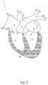
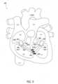
心臓1の様々な特徴が、本開示を理解するのを助けるために、図1を参照して記載されている。心臓1は、4つの室、つまり、左心房2、左心室3、右心室4、および右心房5を備える。中隔10と称される筋肉の壁が、左心房2と右心房5とを分離し、左心室3と右心室4とを分離している。心臓1を通る血流は、僧帽弁6、大動脈弁7、三尖弁8、および肺動脈弁9の4つの弁によって少なくともある程度制御される。僧帽弁6は、左心房2と左心室3とを分離しており、それらの間の血流を制御する。大動脈弁7は、左心室3と大動脈12とを分離しており、それらの間の血流を制御する。三尖弁8は、右心房5と右心室4とを分離しており、それらの間の血流を制御する。肺動脈弁9は、右心室4と肺動脈11とを分離しており、それらの間の血流を制御する。Various features of the heart 1 are described with reference to FIG. 1 to aid in understanding the present disclosure. The heart 1 comprises four chambers: the left atrium 2, the
心臓弁は、本明細書では弁輪と称される比較的密な線維輪と、その弁輪に付着される複数の弁尖または弁葉とを概して備え得る。例えば、三尖弁8、大動脈弁7、および肺動脈弁9は3つの弁尖または弁葉を概して有する。僧帽弁6は2つの弁尖または弁葉を概して有する。弁尖または弁葉の大きさは、弁尖または弁葉が、弁を閉じるために接合し、弁を開くために離れるようになり得る。房室の心臓弁(つまり、僧帽弁および三尖弁)は、弁葉の適切な接合を促進および/または容易化し、弁葉の脱出を防止するために、それぞれの弁の弁葉を固定するための腱索および乳頭筋(図示されていない)の集まりをさらに備え得る。乳頭筋は、例えば、心室壁からの指状の突起を概して備え得る。弁葉は腱索によって乳頭筋に連結されている。Heart valves may generally comprise a relatively dense fibrous ring, referred to herein as the annulus, and multiple cusps or leaflets attached to the annulus. For example, the tricuspid valve 8, the aortic valve 7, and the
健康な心臓では、心臓弁は、心臓のそれぞれの領域および/または血管への血液の流れを少なくともある程度制御するために、心臓周期(例えば、弛緩および収縮)の様々な段階の間に存在する圧力勾配に応じて適切に開閉することができる。身体の他の部分から来る酸素が除去された血液は、肺への輸送のために心臓の右側へと概して流れ、肺からの酸素を含む血液は、身体の他の部分への輸送のために心臓の左側へと概して流れる。In a healthy heart, the heart valves can open and close appropriately in response to pressure gradients that exist during the various phases of the cardiac cycle (e.g., relaxation and contraction) to at least some degree control the flow of blood to each region and/or blood vessel of the heart. Deoxygenated blood coming from other parts of the body generally flows to the right side of the heart for transport to the lungs, and oxygenated blood from the lungs generally flows to the left side of the heart for transport to other parts of the body.
心室拡張期の間(つまり、心室の心筋が弛緩されているとき)、右心室4と右心房5との間の負の圧力差が、三尖弁8を開くように三尖弁8の弁葉を離すように押すことができ、下大静脈15および上大静脈16から来る右心房5における酸素が除去された血液を右心室4へと流すことができる。肺動脈弁9の弁葉は、心室拡張期の間に接合させられ、肺動脈弁9を閉じたままにするために互いと並置したままとなる。左心室3と左心房2との間の負の圧力差は、僧帽弁6を開けるために心室拡張期の間に僧帽弁6の弁葉を離すように押すことができ、肺静脈から来る左心房2における酸素を含む血液を左心室3へと流すことができる。大動脈弁7の弁葉は、心室拡張期の間に接合されたままとでき、大動脈弁7を閉じたままにする。During ventricular diastole (i.e., when the ventricular myocardium is relaxed), a negative pressure difference between the right ventricle 4 and the
心室収縮の間(例えば、心室の心筋が収縮するとき)、右心室4と右心房5との間の正の圧力差が、三尖弁8を閉じるように三尖弁8の弁葉を接合させたまま、または互いと並置させたままにすることができる。適切に接合された弁葉は、右心室4から右心房5への血液の漏れを防止することができる。その間、肺動脈弁9の弁葉は、心室収縮の間に離すように押され、肺への輸送のために、酸素が除去された血液を右心室4から肺動脈11へと送ることができる。肺動脈11は、酸素が除去された血液を心臓の右側から肺へと運ぶことができる。肺動脈11は、肺動脈幹と、肺動脈幹から分岐する左肺動脈14および右肺動脈13とを備え得る。心室収縮の間の左心室3と左心房2との間の正の圧力差は、僧帽弁6を閉じるように、僧帽弁6の弁葉を接合させたままとできる、または互いと並置させたままとできる。適切に接合された弁葉は、左心室3から左心房2への血液の漏れを防止することができる。大動脈弁7の弁葉は、身体の他の部分への輸送のために、左心室3から大動脈12への酸素を含む血液の流れを許容するように、心室収縮の間に離れるように押され得る。During ventricular contraction (e.g., when the ventricular myocardium contracts), a positive pressure difference between the right ventricle 4 and the
病気の心臓弁および/または関連する弁葉(例えば、三尖弁および/または僧帽弁の機能障害)は、弁の漏れおよび/または他の健康上の合併症をもたらす可能性がある。弁狭窄は、弁を狭くさせ得る、または詰まらせ得る。三尖弁狭窄および僧帽弁狭窄は、右心房から右心室への血流および左心房から左心室への血流をそれぞれ制限する可能性がある。弁逆流は、弁が適切に閉じないときに起こる。例えば、逆流は弁葉の不適切な接合のため起こる可能性がある。三尖弁逆流は、右心室が収縮するとき、右心室から右心房へと戻る血流の漏れをもたらす可能性がある。右心房へと戻る血液の漏れは、肺への酸素が除去された血液の非効率的な汲み出しをもたらす可能性がある。僧帽弁逆流は、左心室が収縮するとき、左心室から左心房へと戻る血流の漏れをもたらす可能性がある。逆流が重度である場合、心臓は血液の順流を維持するために拡大し心臓が身体へと十分な血液を汲み出せないときなど、心不全を引き起こす可能性がある。これは、労作の間の息切れから、咳嗽、心臓および肺の周りでの鬱血、脚および足の腫れまで及ぶ症状を作り出す可能性がある。弁の修理が、様々な弁の病気に対処するために実施され得る。より深刻な症例では、弁置換が実施され得る。Diseased heart valves and/or associated leaflets (e.g., tricuspid and/or mitral valve dysfunction) can result in valve leakage and/or other health complications. Valve stenosis can cause the valve to narrow or become clogged. Tricuspid and mitral stenosis can restrict blood flow from the right atrium to the right ventricle and from the left atrium to the left ventricle, respectively. Valve regurgitation occurs when a valve does not close properly. For example, regurgitation can occur due to improper coaptation of the valve leaflets. Tricuspid regurgitation can result in leakage of blood flow back from the right ventricle to the right atrium when the right ventricle contracts. Leaking of blood back to the right atrium can result in inefficient pumping of deoxygenated blood to the lungs. Mitral regurgitation can result in leakage of blood flow back from the left ventricle to the left atrium when the left ventricle contracts. If regurgitation is severe, the heart enlarges to keep blood flowing forward and can lead to heart failure, when the heart cannot pump enough blood to the body. This can create symptoms ranging from shortness of breath during exertion, to coughing, blood congestion around the heart and lungs, and swelling in the legs and feet. Valve repairs can be performed to address various valve diseases. In more severe cases, valve replacements can be performed.
本開示は、三尖弁装置と僧帽弁装置との両方を心室中隔において互いに係留するための装置、システム、および/または方法に関する。三尖弁装置は三尖弁置換部または三尖弁修理部を備え得る。僧帽弁装置は僧帽弁置換部または僧帽弁修理部を備え得る。展開状態において、本明細書に記載されている二重心臓弁係留システムは、中隔を通じて互いに繋がれる僧帽弁の修理部または置換部と三尖弁の修理部または置換部とを備え得る。一部の実施形態では、二重心臓弁係留システムは、中隔横断開口を通じて延びるように構成され、三尖弁置換部と僧帽弁置換部とを互いに繋げ、三尖弁置換部および僧帽弁置換部を中隔に結合する連結器を備え得る。二重心臓弁係留システムは、中隔横断開口の中に位置決めされるように構成される一部分を少なくとも備える係留部を備え得る。連結器は、例えば、係留部における開口を通じて延びる一部分を備える係留部に結合され得る。The present disclosure relates to devices, systems, and/or methods for anchoring both a tricuspid valve device and a mitral valve device to one another at the ventricular septum. The tricuspid valve device may include a tricuspid valve replacement or tricuspid valve repair. The mitral valve device may include a mitral valve replacement or mitral valve repair. In a deployed state, the dual heart valve anchoring system described herein may include a mitral valve repair or replacement and a tricuspid valve repair or replacement that are connected to one another through the septum. In some embodiments, the dual heart valve anchoring system may include a coupler configured to extend through a transseptal opening, connecting the tricuspid valve replacement and the mitral valve replacement to one another and coupling the tricuspid valve replacement and the mitral valve replacement to the septum. The dual heart valve anchoring system may include an anchoring portion having at least a portion configured to be positioned in the transseptal opening. The coupler may be coupled to the anchoring portion having a portion that extends through an opening in the anchoring portion, for example.
一部の実施形態では、僧帽弁修理部および三尖弁修理部は、僧帽弁修理部と三尖弁修理部とを中隔および互いに係留する中隔横断開口を介して互いに結合され得る。一部の実施形態では、僧帽弁修理部と三尖弁置換部とが中隔横断開口を介して互いに結合され得る。一部の実施形態では、僧帽弁置換部と三尖弁修理部とが中隔横断開口を介して互いに結合され得る。In some embodiments, the mitral valve repair and tricuspid valve repair can be coupled to each other via a transseptal opening that anchors the mitral valve repair and tricuspid valve repair to the septum and to each other. In some embodiments, the mitral valve repair and tricuspid valve replacement can be coupled to each other via a transseptal opening. In some embodiments, the mitral valve replacement and tricuspid valve repair can be coupled to each other via a transseptal opening.
心室収縮の間、心室の収縮は、三尖弁装置および僧帽弁装置をそれぞれ右心房および左心房に向けて押し、可及的に望ましくなく装置を押し退けてしまう可能性がある。三尖弁装置および僧帽弁装置を中隔壁に係留することで、それら装置のそれぞれの標的部位における装置の各々のしっかりとした位置決めを容易にすることができる。僧帽弁装置と三尖弁装置とを互いに繋ぐことで、心臓の収縮によってそれら装置に発揮される力を有利に平衡させることができる。例えば、三尖弁装置に発揮される力は、僧帽弁装置に発揮される力に抗して平衡させられ、それによって、中隔壁に発揮される力の不平衡を低減または排除させることができる。中隔壁に発揮される力の不平衡を低減または排除することで、三尖弁装置および僧帽弁装置を係留することによる中隔壁への損傷を低減または防止することができる。During ventricular contraction, the contraction of the ventricles pushes the tricuspid and mitral valve apparatus toward the right and left atria, respectively, potentially displacing the apparatus undesirably. Anchoring the tricuspid and mitral valve apparatus to the septal wall can facilitate secure positioning of each of the apparatus at their respective target sites. Tethering the mitral and tricuspid valve apparatus to each other can advantageously balance the forces exerted on the apparatus by cardiac contraction. For example, the forces exerted on the tricuspid valve apparatus can be balanced against the forces exerted on the mitral valve apparatus, thereby reducing or eliminating the imbalance of forces exerted on the septal wall. Reducing or eliminating the imbalance of forces exerted on the septal wall can reduce or prevent damage to the septal wall due to tethering the tricuspid and mitral valve apparatus.
三尖弁装置および僧帽弁装置を中隔壁に係留することで、それら装置のそれぞれの標的位置の中でのしっかりとした位置決めを達成するために装置自体において縮小した係留特徴部を備える弁装置の使用を可能にすることができる。弁装置は、所望の係留を達成するために、自然弁への結合のために縮小した係留特徴部を有することができ、縮小した大きさおよび/または低減した複雑性を有する弁装置の使用を可能にする。例えば、本明細書に記載されているような二重心臓弁係留システムは、より短い輪郭および/またはより細い直径を有し得る三尖弁置換部および/または僧帽弁置換部を備え得る。三尖弁置換部および/または僧帽弁置換部は、埋込みのために圧縮するのがより容易であり得る、および/または、製作するのがより容易であり得る。Anchoring the tricuspid and mitral valve devices to the septal wall can enable the use of valve devices with reduced anchoring features in the device itself to achieve firm positioning of the devices in their respective target locations. The valve devices can have reduced anchoring features for coupling to the native valve to achieve the desired anchoring, enabling the use of valve devices with reduced size and/or reduced complexity. For example, a dual heart valve anchoring system as described herein can include a tricuspid and/or mitral valve replacement that can have a shorter profile and/or a thinner diameter. The tricuspid and/or mitral valve replacement can be easier to compress for implantation and/or easier to fabricate.
一部の実施形態では、本明細書に記載されている1つまたは複数のシステムは、低侵襲経カテーテル手法を用いて有利に送達され得る。置換三尖弁および置換僧帽弁の両方が、単一の外科的処置を用いたそれら装置のそれぞれの標的部位における位置決めを含め、低侵襲経カテーテル手法を用いて送達できる。例えば、三尖弁置換部と僧帽弁置換部との両方を担持する送達カテーテルが、下大静脈(IVC)または上大静脈(SVC)を通じて右心房(RA)へと挿入され、RAから右心室(RV)へと挿入され、続いて中隔壁を介して左心室(LV)へと挿入され得る。僧帽弁置換部の標的部位に到達した後、僧帽弁置換部は送達カテーテルから解放され得る。続いて、送達カテーテルは、挿入された同じ経路に沿ってかまたは実質的に沿って後退させられ得る。送達カテーテルが三尖弁置換部のための標的部位へと後退させられた後、三尖弁置換部は展開され得る。このような処置は、より小さい侵襲性の経皮の送達方法を提供でき、外科処置の間の患者への外傷を低減し、回復を容易にする。In some embodiments, one or more of the systems described herein may be advantageously delivered using a minimally invasive transcatheter approach. Both the replacement tricuspid valve and the replacement mitral valve may be delivered using a minimally invasive transcatheter approach, including positioning the devices at their respective target sites using a single surgical procedure. For example, a delivery catheter carrying both the tricuspid valve replacement and the mitral valve replacement may be inserted through the inferior vena cava (IVC) or superior vena cava (SVC) into the right atrium (RA), from the RA into the right ventricle (RV), and then through the septal wall into the left ventricle (LV). After reaching the target site for the mitral valve replacement, the mitral valve replacement may be released from the delivery catheter. The delivery catheter may then be retracted along or substantially along the same path it was inserted. After the delivery catheter has been retracted to the target site for the tricuspid valve replacement, the tricuspid valve replacement may be deployed. Such a procedure may provide a less invasive percutaneous delivery method, reducing trauma to the patient during the surgical procedure and facilitating recovery.
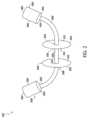
図2は、2つの心臓弁置換部を備える二重心臓弁係留システム100の例の概略図である。一部の実施形態では、二重心臓弁係留システム100は、低侵襲経カテーテル手法を用いて標的部位へと送達され得る。二重心臓弁係留システム100は、三尖弁置換部200と、僧帽弁置換部300と、三尖弁置換部200と僧帽弁置換部300とを互いに結合する連結器400とを備え得る。連結器400は、心室中隔に形成された中隔横断開口を通じて延びるように構成され得る。本明細書においてさらに詳細に記載されているように、連結器400は、心臓の収縮によって三尖弁置換部200に発揮される力を、心臓の収縮によって僧帽弁置換部300に発揮される力に抗して平衡させる一方で、三尖弁置換部200および僧帽弁置換部300を中隔に係留するように構成され得る。2 is a schematic diagram of an example of a dual heart
図2を再び参照すると三尖弁置換部200は、第1の遠位端202と第2の遠位端204とを有する三尖弁本体部分206を備え得る。僧帽弁置換部300は、第1の遠位端302と第2の遠位端304とを有する僧帽弁本体部分306を備え得る。連結器400は、三尖弁置換部200および僧帽弁置換部300のそれぞれの第2の端204および304に結合され得る。本明細書においてさらに詳細に記載されているように、連結器400は、三尖弁置換部200および僧帽弁置換部300の心室の向かい合う端に結合され得る。例えば、連結器400は、三尖弁置換部200の第2の遠位端204に結合される第1の部分402と、僧帽弁置換部300の第2の遠位端304に結合される第2の部分404とを有し得る。図2は、連結器400が三尖弁置換部200および僧帽弁置換部300のそれぞれの遠位端に結合され得ることを示しているが、連結器400が三尖弁置換部200および/または僧帽弁置換部300の1つまたは複数の他の部分に結合されてもよいことは、理解されるものである。2, the
一部の実施形態では、連結器が、心臓弁置換部の本体部分の遠位端ではなく、心臓弁置換部の本体部分の遠位端に近接する遠位部分など、心臓弁置換部の遠位部分に結合され得る。一部の実施形態では、連結器は心臓弁置換部の本体部分の中心部分に結合され得る。一部の実施形態では、連結器は、本明細書に記載されているような心臓弁置換部の1つまたは複数の一部分を含む複数の場所において、心臓弁置換部に結合され得る。連結器が心臓弁置換部に結合する場所は、中隔への係留の所望の角度、および/または、他の心臓弁置換部への結合を提供するように選択され得る。In some embodiments, the coupler may be coupled to a distal portion of the heart valve replacement, such as a distal portion proximate the distal end of the body portion of the heart valve replacement, rather than at the distal end of the body portion of the heart valve replacement. In some embodiments, the coupler may be coupled to a central portion of the body portion of the heart valve replacement. In some embodiments, the coupler may be coupled to the heart valve replacement in multiple locations, including one or more portions of the heart valve replacement as described herein. The location at which the coupler couples to the heart valve replacement may be selected to provide a desired angle of anchoring to the septum and/or coupling to other heart valve replacements.
本明細書においてさらに詳細に記載されているように、一部の実施形態では、連結器の長さはあらかじめ決定され得る。例えば、長さは、二重心臓弁係留システムを担持する送達カテーテルの患者への挿入の前に選択され得る。一部の実施形態では、長さは埋込処置の間に調整可能であり得る。例えば、長さは、個人の生体構造に応じて埋込処置の間に調整され得る。As described in further detail herein, in some embodiments, the length of the coupler may be predetermined. For example, the length may be selected prior to insertion of a delivery catheter carrying the dual heart valve anchoring system into a patient. In some embodiments, the length may be adjustable during the implantation procedure. For example, the length may be adjusted during the implantation procedure depending on the individual's anatomy.
一部の実施形態では、二重心臓弁係留システム100は、中隔横断開口の中に固定されるように構成される一部分を少なくとも備える係留部500を備え得る。係留部500は、係留部本体506と、係留部本体506の反対にある遠位端516、518に結合される第1の中隔接触部502および第2の中隔接触部504とを備え得る。係留部は、係留部本体506の長手方向の全長に沿って延びる内腔520を備え得る。In some embodiments, the dual heart
係留部500がその標的部位に位置決めされている間、係留部本体506の第1の遠位端516が中隔の右心室側表面に隣接または近接して位置決めでき、係留部本体506の第2の遠位端518が中隔の左心室側表面に隣接または近接して位置決めできる。一部の実施形態では、係留部本体506の長手方向の長さは、その標的部位において中隔の厚さと同じかまたは実質的に同じであり得る。係留部500は、内腔520が開口において中隔の全厚にわたって延びるように、中隔横断開口に位置決めされ得る。連結器400は、三尖弁置換部200と僧帽弁置換部300とを互いに結合するために内腔520を通じて延び得る。While the
第1の中隔接触部502は、中隔の右心室側表面に接触または近接して位置決めされるように構成され、第2の中隔接触部504は、中隔の左心室側表面に接触または近接して位置決めされるように構成され得る。図2に示されているように、係留部本体506の遠位端516、518にそれぞれ結合される第1の中隔接触部502および第2の中隔接触部504は、連結器400が内腔520を通じて延び得るように、内腔520に対応する開口を有し得る。係留部500を通じて連結器400を延ばすことは、係留から中隔への損傷を低減または防止する一方で、中隔への三尖弁置換部200および僧帽弁置換部300の安定した係留を容易にすることができる。The first
第1の中隔接触部502および第2の中隔接触部504は、中隔横断開口における係留部500の安定した位置決めを容易にするために、中隔と係合するように構成され得る。中隔の一部分が第1の中隔接触部502と第2の中隔接触部504との間にあることができ、例えば、第1の中隔接触部502と第2の中隔接触部504とによって挟まれる。第1の中隔接触部502は、右心室を向くように構成される第1の表面508と、中隔の右心室側表面を向くように構成される第2の表面510とを有し得る。一部の実施形態では、第2の表面510は、右心室側表面に隣接して接触した状態で位置決めされるように構成され得る。一部の実施形態では、第2の表面510は、右心室側表面に近接するが接触しない状態であり得る。第2の中隔接触部504は、左心室を向くように構成される第1の表面512と、中隔の左心室側表面を向くように構成される第2の表面514とを有し得る。一部の実施形態では、第2の表面514は、左心室側表面に隣接して接触した状態で位置決めされるように構成され得る。一部の実施形態では、第2の表面514は、左心室側表面に近接するが接触しない状態であり得る。The first
図2を参照して記載された第1の中隔接触部502および第2の中隔接触部504は、内腔520の全周の周りで延びる円形または実質的な円形を備え得るが、中隔接触部が内腔520の周囲の周りで一部だけで延びてもよいことは理解されるものである。一部の実施形態では、中隔接触部は、1つまたは複数の突起および/または刻み目など、係留部500のしっかりとした位置決めを容易にするために、中隔を向く面に1つまたは複数の特徴を備えてもよい。The first
内腔520は任意の数の断面の形を有することができる。一部の実施形態では、内腔520の断面の形は、円形または楕円形を含む弓状の形を含む。一部の実施形態では、内腔520の断面の形は、矩形または三角形など、真っ直ぐな縁を含む。内腔520の断面の形は、例えば連結器400を受け入れるために、連結器400の断面の形に基づいて選択され得る。直径などの内腔520の断面の寸法は、連結器400を受け入れるように選択され得る。本明細書においてさらに詳細に記載されているように、二重心臓弁係留システムは複数の連結器を備えてもよい。内腔520の断面の形および/または寸法は、複数の連結器を受け入れるように構成され得る。The
一部の実施形態では、係留部500は、左心室と右心室との間の血流を防止または低減するために、中隔横断開口の閉塞を容易にすることができる。例えば、内腔520は、係留部500がその標的部位において展開されている間に係留部500を越えての血液の流れを許容することなく、または実質的に許容することなく、連結器400を収容するための寸法および断面の形を有し得る。一部の実施形態では、内腔520の断面の直径は、連結器400の断面の直径と同じまたは同様である。一部の実施形態では、内腔520は、連結器400と同じまたは同様の断面の形を有し得る。In some embodiments, the
一部の実施形態では、係留部500および/または連結器400は、それぞれの標的部位への経カテーテル送達を容易にするように構成される柔軟、変形可能、および/または弾性の生体適合性の材料を含み得る。形状記憶を有する材料が使用されてもよい。係留部500および/または連結器400は、柔軟、変形可能、および/または弾性の生体適合性のポリマおよび/または金属合金のうちの1つまたは複数を含み得る。一部の実施形態では、係留部500および/または連結器400は、ポリプロピレン(PP)、ポリエチレン(PE)、ポリメチルメタクリレート(PMMA)、ポリスチレン(PS)、ポリ塩化ビニル(PVC)、ポリテトラフルオロエチレン(PTFE)、ポリウレタン(PU)、ポリアミド(ナイロン)、ポリエチレンテレフタレート(PET)、ポリエーテルスルホン(PES)、ポリエーテルイミド(PEI)、ポリエーテルエーテルケトン(PEEK)、ポリ塩化ビニル(PVC)、およびポリ(乳酸-co-グリコール)酸(PLGA)のうちの1つまたは複数を含み得る。一部の実施形態では、係留部500および/または連結器400はステンレス鋼および/またはニッケルチタンを含み得る。一部の実施形態では、連結器400は柔軟なコードを備え得る。連結器400は柔軟なコードであり得る。一部の実施形態では、連結器400はニチノールワイヤを備え得る。例えば、連結器400はニチノールワイヤであり得る。一部の実施形態では、連結器400はポリマワイヤであり得る。一部の実施形態では、係留部500は、縮小された輪郭構成で送達カテーテルを通じて前進させることができるように、形状記憶材料を備え得る。標的部位への送達の後、係留部500は送達カテーテルから解放され、拡張した輪郭構成を取ることができる。In some embodiments, the
一部の実施形態では、二重心臓弁係留システムは係留部を備えなくてもよい。例えば、二重心臓弁係留システムは、中隔において、および/または中隔を通じて位置決めされる係留部に結合されることなく、中隔横断開口を通じて延びる連結器を有し得る。In some embodiments, the dual heart valve anchoring system may not include an anchor portion. For example, the dual heart valve anchoring system may have a coupler that extends through a transseptal opening without being coupled to an anchor portion positioned at and/or through the septum.
図3は、心臓において標的部位に位置決めされた二重心臓弁係留システム100を示す概略図である。二重心臓弁係留システム100は、自然三尖弁の中に位置決めされた一部分を少なくとも備える三尖弁置換部200と、自然僧帽弁の中に位置決めされた一部分を少なくとも備える僧帽弁置換部300とを有し得る。連結器400は、三尖弁置換部200と僧帽弁置換部300とを互いに結合させることができる。係留部500は心室中隔において中隔横断開口に位置決めされ得る。連結器400は、三尖弁置換部200と僧帽弁置換部300とを結合するために係留部500を通じて延び得る。FIG. 3 is a schematic diagram showing a dual heart
三尖弁本体部分206の一部分が自然三尖弁の1つまたは複数の部品と近接および/または直接的に接触できる。三尖弁置換部200の第1の遠位端202は右心房に向けて配向でき、第2の遠位端204は右心室に向けて配向できる。一部の実施形態では、第2の遠位端204は右心室の中に位置決めされ得る。一部の実施形態では、第1の遠位端202は右心房の中に位置決めされ得る。僧帽弁本体部分306の一部分が自然僧帽弁の1つまたは複数の部品と近接および/または直接的に接触できる。第1の遠位端302は左心房に向けて配向でき、第2の遠位端304は左心室に向けて配向できる。一部の実施形態では、第2の遠位端304は左心室の中に位置決めされ得る。一部の実施形態では、第1の遠位端302は左心房の中に位置決めされ得る。連結器400の第1の部分402は、右心室に向けて配向された第2の遠位端204など、三尖弁置換部200の遠位部分に結合でき、連結器400の第2の部分404は、左心室に向けて配向された第2の遠位端304など、僧帽弁置換部300の遠位部分に結合され得る。A portion of the tricuspid
心室収縮の間、心室の収縮によって三尖弁置換部200および僧帽弁置換部300に発揮される力は、三尖弁置換部200および僧帽弁置換部300をそれぞれ右心房および左心房に向けて押すことができる。三尖弁置換部200および僧帽弁置換部300に発揮される力は、三尖弁置換部200および僧帽弁置換部300を、心臓の中におけるそれらの対応する所望の位置から押し退けようとする可能性がある。中隔において係留部500に結合される連結器400は、三尖弁置換部200および僧帽弁置換部300をそれらのそれぞれの標的位置において保持することを容易にするように、心臓によってそれら置換部に発揮される力に抗するための力を提供することができる。連結器400の長さは、連結器400がきつく引っ張られる一方で、三尖弁置換部200および僧帽弁置換部300が収縮期の間に右心房および左心房に向けて押され、三尖弁置換部200および僧帽弁置換部300を所定位置で保持するように選択され得る。連結器400の長さは、心臓が収縮期間にあるときにピンと張られるように選択され得る。一部の実施形態では、三尖弁と僧帽弁との間の連結器400の長さはあらかじめ決定され得る。例えば、連結器400の長さは、送達カテーテルへの挿入の前に選択され得る。本明細書においてさらに詳細に記載されているように、一部の実施形態では、長さは調整可能とでき、例えば埋込処置の間に決定される。During ventricular contraction, forces exerted on the tricuspid and
係留部500は、中隔への二重心臓弁係留システム100の所望の係留を提供するために、中隔に沿う場所に位置決めされ得る。例えば、中隔横断開口は、係留の所望の角度を提供する、および/または、所望の強度を提供することができる中隔の領域を選択する一方で、係留部500および/または連結器400による腱索との干渉を低減または回避するように、中隔に沿う場所において形成され得る。一部の実施形態では、中隔横断開口は、中隔壁に沿う中間点においてかまたはその中間に近接して形成され得る。一部の実施形態では、中隔横断開口は、中隔壁に沿う中間点の上方に形成され得る。The anchoring
本明細書に記載されているように、心臓が収縮期間にある間、自然三尖弁および自然僧帽弁は三尖弁置換部200および僧帽弁置換部300にそれぞれ力を発揮して、置換三尖弁置換部200および置換僧帽弁置換部300を右心房および左心房に向けて押すことができる。中隔横断開口は、力の力ベクトルが中隔への係留の所望の角度を三尖弁置換部200および僧帽弁置換部300に提供するように交差する中隔における領域に、またはその領域に近接して、位置させることができる。一部の実施形態では、中隔横断開口は交差位置の上方に形成され得る。As described herein, during a period of systole, the native tricuspid and mitral valves can exert forces on the tricuspid and
一部の実施形態では、二重心臓弁係留システムは係留部を備えない。図4は、心臓におけるその標的部位において位置決めされる二重心臓弁係留システム110の例を示す概略図であり、二重心臓弁係留システム110は係留部を備えない。二重心臓弁係留システム110は、三尖弁置換部200と僧帽弁置換部300とを互いに結合する連結器410を有し得る。三尖弁置換部200は、自然三尖弁の中に位置決めされる一部分を少なくとも備え、僧帽弁置換部300は、自然僧帽弁の中に位置決めされる一部分を少なくとも備え得る。二重心臓弁係留システム110は係留部500を備えない。図4に示されているように、連結器410は、係留部に結合されることなく中隔横断開口を通じて延びることができる。In some embodiments, the dual heart valve anchoring system does not include an anchoring portion. FIG. 4 is a schematic diagram illustrating an example of a dual heart
連結器410の第1の部分412は、第2の遠位端204などにおいて、三尖弁置換部200に結合され得る。連結器410の第2の部分414は、第2の遠位端304などにおいて僧帽弁置換部300に結合され得る。連結器410は、中隔横断開口を通じて延びるように構成される中隔横断部分416を備え得る。例えば、中隔横断部分416は中隔との直接的な接触にあり得る。The
一部の実施形態では、連結器410の中隔横断部分416は、中隔との係合、中隔の保護、および/または中隔横断開口の閉塞のための1つまたは複数の特徴を備え得る。中隔横断部分416は、中隔と係合することができる、および/または、中隔横断開口を通じた連結器410の挿入を容易にするための中隔保護特徴部を有し得る。中隔横断開口の閉塞は、左心室と右心室との間の血流を低減または排除することができる。二重心臓弁係留システム110は、係留部を備える二重心臓弁係留システムなどと比較して、よりコンパクトにできる、および/または、縮小した輪郭を有し得る。コンパクトな大きさおよび/または縮小した輪郭は、送達および/または標的部位における埋込みの容易性を提供することができる。In some embodiments, the
図5Aは、調整可能連結器420を備える二重心臓弁係留システム120の概略図である。連結器420の長さは埋込処置の間に調整され得る。二重心臓弁係留システム120は、心臓における標的場所において位置決めされているように、図5Aに示されている。二重心臓弁係留システム120は三尖弁置換部200と僧帽弁置換部300とを備え得る。連結器420は、三尖弁置換部200に結合される第1の部分422と、僧帽弁置換部300に結合される第2の部分424とを有し得る。連結器420は、中隔横断開口に位置決めされる係留部500を通じて延びることができる。三尖弁置換部200、僧帽弁置換部300、および係留部500は、図3を参照してなどで本明細書に記載されているように、心臓に位置決めされ得る。5A is a schematic diagram of a dual heart
一部の実施形態では、連結器420の長さは患者の生体構造を受け入れるために調整され得る。例えば、連結器420の長さは、二重心臓弁係留システム120が患者へと挿入された後に調整され得る。本明細書でさらに詳細に記載されているように、連結器420の長さは、二重心臓弁係留システム120がその標的部位に位置決めされた後を含め、埋込処置の間に1回または複数回で調整され得る。In some embodiments, the length of the
一部の実施形態では、二重心臓弁係留システム120は、調整が個人の具体的な生体構造に基づいて実施された後、連結器420の長さを選択された長さで固定するように構成される係止機構600を備え得る。係止機構600は、適切な長さが選択された後に展開、作動、および/または起動させることができ、連結器420の長さを決定された長さにおいて係止する。一部の実施形態では、係止機構600は、三尖弁置換部300の一部に結合され得る、または、三尖弁置換部300の一部として統合され得る。In some embodiments, the dual heart
図5Aは、二重心臓弁係留システム120が1つの係止機構600を備え得ることを示しているが、2つ以上の係止機構600が含まれ得ることは理解されるものである。一部の実施形態では、三尖弁置換部200、僧帽弁置換部300、および係留部500のうちの1つまたは複数は、それに結合される係止機構600、または、それと一体にされる係止機構600を備え得る。While FIG. 5A illustrates that the dual heart
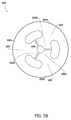
図5Bは、係止機構600の例の上から下へ見たときの平面図を示している。係止機構600は開状態および閉状態にあり得る。開状態において、係止機構600はそれを通じて連結器420を自由に移動させることができる。閉状態において、係止機構600は、連結器420を選択された長さで係止するように、連結器420の移動を低減または回避することができる。図5Bは、閉状態における係止機構600を示している。Figure 5B shows a top-down plan view of an
係止機構600は、それぞれの第1の遠位部分602a、604a、606aにおいて互いに結合される第1の移動可能フラップ602、第2の移動可能フラップ604、および第3の移動可能フラップ606を備え得る。第1の移動可能フラップ602、第2の移動可能フラップ604、および第3の移動可能フラップ606の第2の遠位部分602b、604b、606bは開口608を定め得る。連結器420は開口608を通じて延ばされ得る。The
開状態を達成するために、移動可能フラップ602、604、606は、開口608を拡大するために、第2の遠位部分602b、604b、および606bを互いから離すように押すために、第1の方向において移動させられ得る。連結器420は、例えば、埋込処置の間に連結器420の長さの調整を可能とするために、係止機構が開状態にあるときに開口608を通じて自由に移動することができる。移動可能フラップ602、604、606は、閉状態を達成し、開口608の大きさを小さくするように第2の遠位部分602b、604b、および606bを一緒により近くへと移動させるために、第1の方向と反対の第2の方向において移動させられるように構成され得る。開口608を定める第2の遠位部分602b、604b、および606bの1つまたは複数の縁は、係止機構600が開口608を通じた連結器420の移動を低減または防止するように、閉状態にある間に連結器420に十分に接触するように構成でき、それによって、連結器420を調整された長さで係止または実質的に係止することを容易にする。例えば、開口608は、第2の遠位部分602b、604b、および606bの1つまたは複数の縁が開口608を通じた連結器420の移動を低減または防止するのに十分となるように連結器420と接触できるように、閉状態において連結器420の断面領域と同じであり得る、または、その断面領域より小さい大きさであり得る。To achieve the open state, the
一部の実施形態では、係止機構600は非平面状の構成を有し得る。例えば、移動可能フラップ602、604、606は、第1の方向(例えば、紙面へと向かう方向)におけるフラップ602、604、606の移動が開状態を達成するために第2の遠位部分602b、604b、606bをさらに離すように押すように、互いに対してある角度で配向され、図5Bの紙面へと向かう方向に延びることができる。第2の方向(例えば、紙面から向かってくる方向)におけるフラップ602、604、606の移動は、閉状態を達成するために第2の遠位部分602b、604b、606bを一緒により近くへとさせることができる。In some embodiments, the
係止機構600を開閉することは、様々な技術を用いて制御させることができる。一部の実施形態では、係止機構600を開閉することは圧力によって起動させられ得る。例えば、圧力の適用は、移動可能フラップ602、604、および606を移動させて係止機構を開けるおよび/または閉じるために使用できる。一部の実施形態では、連結器420を移動可能フラップ602、604、および606に接触させることは、係止機構600の開および/または閉を引き起こすことができる。例えば、連結器420を移動可能フラップ602、604、および606に接触させることと、連結器420を移動可能フラップ602、604、および606に対して移動させることとは、移動可能フラップ602、604、および606を所望の方向に移動させることができる。連結器420と移動可能フラップ602、604、および606とを接触させている間に連結器420を第1の方向に移動させることで、係止機構600を開けることができ、連結器420と移動可能フラップ602、604、および606とを接触させている間に連結器420を第2の方向に移動させることで、係止機構600を閉じることができる。一部の実施形態では、連結器420は、移動可能フラップ602、604、および606との係合を容易にするために、突起および/または刻み目などの1つまたは複数の特徴部を備え得る。Opening and closing the
図6は、剛体または半剛体の一部分436を備える連結器430を備える二重心臓弁係留システム130の概略図である。二重心臓弁係留システム130は、心臓における標的部位において位置決めされているとして示されている。三尖弁置換部200、僧帽弁置換部300、および係留部500は、図3を参照して記載されているものなど、それぞれの標的位置において位置決めされ得る。連結器430は、中隔横断開口において位置決めされるように構成される係留部500を通じて延びることができ、三尖弁置換部200と僧帽弁置換部300とを互いに結合することができる。連結器430は、三尖弁置換部200に結合される第1の部分432と、僧帽弁置換部300に結合される第2の部分434とを有し得る。6 is a schematic diagram of a dual heart
連結器430の剛体または半剛体の一部分436は、中隔横断開口を通じて延び、例えば、中隔横断開口において位置決めされるように構成される係留部500を通じて延びるように構成され得る。剛体または半剛体の一部分436は、右心室と左心室との一方または両方へと延びることができる。例えば、剛体または半剛体の一部分436は、右心室へと延びるように構成される第1の区分436aと、左心室へと延びるように構成される第2の区分436bとを備え得る。第1の区分436aおよび/または第2の区分436bの長手方向の長さは、中隔への三尖弁置換部200および僧帽弁置換部300の所望の係留を提供するように選択され得る。一部の実施形態では、第1の区分436aおよび/または第2の区分436bの長さは、中隔への三尖弁置換部200および僧帽弁置換部300の所定の角度の繋ぎを提供するように選択され得る。第1の区分436aおよび/または第2の区分436bの長さは、中隔への三尖弁置換部200および僧帽弁置換部300の所望の係留を提供する一方で、腱索との干渉を低減または回避するための中隔における場所に、中隔横断開口を位置決めすることを可能とするように選択され得る。The rigid or
一部の実施形態では、第1の区分436aの長手方向の長さは第2の区分436bの長手方向の長さと同じまたは同様であり得る。一部の実施形態では、第1の区分436aの長手方向の長さは第2の区分436bの長さと異なる。第1の区分436aおよび/または第2の区分436bの長手方向の長さは、あらかじめ決定され得る、または調整可能であり得る。例えば、第1の区分436aおよび/または第2の区分436bの長手方向の長さは、二重心臓弁係留システム130を患者へと挿入する前に選択できる。一部の実施形態では、第1の区分436aおよび/または第2の区分436bの長さは、所望の係留を提供するために、個人の生体構造に基づいて、埋込処置の間に調整され得る。一部の実施形態では、第1の区分436aおよび/または第2の区分436bの長さは、患者への二重心臓弁係留システム130の挿入の後に調整できる。例えば、第1の区分436aの長さおよび第2の区分436bの長さは、剛体または半剛体の一部分436を係留部500の内腔520の中で前または後に移動させることで調整できる。一部の実施形態では、剛体または半剛体の一部分436は、第1の区分436aの長さを縮小する一方で第2の区分436bの長さを増加させるために、遠位へと並進させられ得る。一部の実施形態では、剛体または半剛体の一部分436は、第2の区分436bの長さを縮小する一方で第1の区分436aの長さを増加させるために、近位へと並進させられ得る。In some embodiments, the longitudinal length of the
連結器430は、ポリマ材料および/または金属材料を含め、本明細書に記載されている1つまたは複数の生体適合性の材料を含み得る。一部の実施形態では、連結器430の剛体または半剛体の一部分436は、連結器430の残りの部分と異なる材料を含み得る。一部の実施形態では、連結器430の剛体または半剛体の一部分436は、連結器430の残りの部分と同じ材料を備え得る。The
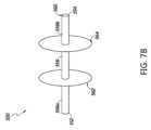
図7Aは、右心室および左心室へと延びるように構成される剛体または半剛体の一部分をそれぞれ備える係留部550を備える二重心臓弁係留システム140の例の概略図である。二重心臓弁係留システム140は、三尖弁置換部200と、僧帽弁置換部300と、三尖弁置換部200と僧帽弁置換部300とを互いに結合する連結器400とを備え得る。連結器400は、中隔横断開口に位置決めされる係留部550を通じて延びることができる。三尖弁置換部200および僧帽弁置換部300は、図3を参照して記載されているものなど、心臓に位置決めされ得る。7A is a schematic diagram of an example of a dual heart
図7Bは係留部550の概略図である。係留部550は、右心室へと延びるように構成される第1の剛体または半剛体の一部分556aと、左心室へと延びるように構成される第2の剛体または半剛体の一部分556bとを備える係留本体部分556を備え得る。例えば、係留本体部分556は、右心室へと延びる第1の遠位端552と、左心室へと延びる第2の遠位端554とを備え得る。第1の剛体または半剛体の一部分556aは、第1の遠位端552が右心室に位置決めされるように右心室へと延びることができ、第2の剛体または半剛体の一部分556bは、第2の遠位端554が左心室に位置決めされるように左心室へと延びることができる。係留部550は、連結器400が三尖弁置換部200と僧帽弁置換部300とを互いに結合するために挿入され得るように係留本体部分556の長手方向の全長に沿って延びる内腔560を備え得る一方で、係留部550は中隔横断開口に位置決めされる。7B is a schematic diagram of the anchoring
係留部は、係留本体部分556から延び、中隔と係合するように離間される第1の中隔接触部562および第2の中隔接触部564を備え得る。一部の実施形態では、第1の中隔接触部562および第2の中隔接触部564は、図2を参照して記載された第1の中隔接触部502および第2の中隔接触部504の1つまたは複数の特徴部を備え得る。The anchoring portion may include a first
係留部500の剛体または半剛体の一部分556a、556bは、中隔への三尖弁置換部200および僧帽弁置換部300の所望の係留を容易にするために、右心室および左心室へとそれぞれ延びるように構成され得る。一部の実施形態では、第1の剛体もしくは半剛体の一部分556aの長手方向の寸法、および/または第2の剛体もしくは半剛体の一部分556bの長手方向の寸法は、三尖弁置換部200および僧帽弁置換部300が腱索と干渉また実質的に干渉することなく中隔に適切に係留され得るように、選択され得る。The rigid or
一部の実施形態では、第1の剛体または半剛体の一部分556aの長手方向の長さと第2の剛体または半剛体の一部分556bの長手方向の長さとは同じまたは同様であり得る。一部の実施形態では、第1の剛体または半剛体の一部分556aの長手方向の長さと第2の剛体または半剛体の一部分556bの長手方向の長さとは異なり得る。一部の実施形態では、係留部500は、両方ではなく、第1の剛体もしくは半剛体の一部分556aまたは第2の剛体もしくは半剛体の一部分556bのいずれかを備え得る。In some embodiments, the longitudinal length of the first rigid or
係留部550は、ポリマ材料および/または金属材料を含め、本明細書に記載されている1つまたは複数の生体適合性の材料を含み得る。一部の実施形態では、係留部550の剛体または半剛体の一部分556a、556bは、係留部550の残りの部分と異なる材料を含み得る。一部の実施形態では、係留部550の剛体または半剛体の一部分556a、556bは、係留部550の残りの部分と同じ材料を含み得る。The
一部の実施形態では、二重心臓弁係留システム140は、本明細書に記載されているような1つまたは複数の他の特徴部を備え得る。一部の実施形態では、二重心臓弁係留システム140は複数の連結器400を備え得る。一部の実施形態では、二重心臓弁係留システム140は1つまたは複数の調整可能連結器420を備え得る。一部の実施形態では、二重心臓弁係留システム140は、剛体または半剛体の一部分436を備える連結器430のうちの1つまたは複数を備え得る。例えば、複数の連結器は係留部550を通じて延び得る。複数の連結器のそれぞれの遠位端は、三尖弁置換部200および僧帽弁置換部300のそれぞれの遠位端における対応する位置に結合され得る。In some embodiments, the dual heart
一部の実施形態では、二重心臓弁係留システムが複数の連結器を備えることができ、複数の連結器は同じ係留部を通じて延びる。図8は、3つの連結器400を備える二重心臓弁係留システム150の例の概略図である。二重心臓弁係留システム150は、標的部位において位置決めされているとして示されている。二重心臓弁係留システム150は、図3を参照して記載されているものなど、それぞれの標的部位において位置決めされる三尖弁置換部200、僧帽弁置換部300、および係留部500を備え得る。3つの連結器400は、三尖弁置換部200と僧帽弁置換部300とを互いに結合させることができる。In some embodiments, the dual heart valve anchoring system can include multiple connectors, with the multiple connectors extending through the same anchoring portion. FIG. 8 is a schematic diagram of an example of a dual heart
一部の実施形態では、3つの連結器400の対応する端は、三尖弁置換部200および僧帽弁置換部300のそれぞれの遠位端に結合され得る。例えば、3つの連結器400の各々の端の第1の部分402は、右心室に向けて配向される三尖弁置換部200の第2の遠位端204に結合され得る。3つの連結器400の各々の端の第2の部分404は、左心室に向けて配向される僧帽弁置換部300の第2の遠位端304に結合され得る。連結器400が結合される三尖弁置換部200の第2の遠位端204における場所と僧帽弁置換部300の第2の遠位端304における場所とは、中隔への所望の係留を提供するように選択され得る。一部の実施形態では、連結器400が三尖弁置換部200および/または僧帽弁置換部300に結合される場所は、対応する第2の遠位端204、304にわたって均等に分配され得る。例えば、連結器400が第2の遠位端204、304に結合される場所は、第2の遠位端204、304の周辺の周りに均等に分配され得る。In some embodiments, corresponding ends of the three
3つの連結器400は同じ中隔横断開口を通じて延びることができる。例えば、3つの連結器400は、中隔横断開口に位置決めされる係留部500を通じて延びる対応する部分を各々備え得る。一部の実施形態では、3つの連結器400のうちの1つまたは複数についての長さは、患者への挿入の前に選択されるなど、あらかじめ決定され得る。The three
一部の実施形態では、二重心臓弁係留システム150は、本明細書に記載されているような1つまたは複数の他の特徴部を備え得る。一部の実施形態では、二重心臓弁係留システム150は、係留部500ではなく係留部550を備え得る。一部の実施形態では、二重心臓弁係留システム150は、剛体または半剛体の一部分436を備える連結器430のうちの1つまたは複数を備え得る。一部の実施形態では、二重心臓弁係留システム150は1つまたは複数の調整可能連結器420を備え得る。一部の実施形態では、3つの連結器のうちの1つまたは複数についての長さが、他の連結器から独立して、埋込処置の間に調整され得る。例えば、3つの連結器は、各々の連結器が係留部の内腔の中で他の連結器に対して移動できるように、係留部の中で互いに結合されなくてもよい。一部の実施形態では、係留部を通じて延びる3つの連結器の対応する一部分が互いと結合される。一部の実施形態では、二重心臓弁係留システム150は、所望の長さが選択された後に連結器の長さを固定するために、本明細書に記載されているような1つまたは複数の係止機構600を備え得る。In some embodiments, the dual heart
一部の実施形態では、二重心臓弁係留システムが複数の連結器を備えることができ、複数の連結器は対応する係留部を通じて各々が延びる。図9は、3つの連結器400と3つの係留部500とを備える二重心臓弁係留システム160の例の概略図である。二重心臓弁係留システム160は、標的部位において位置決めされているとして示されている。二重心臓弁係留システム160は三尖弁置換部200と僧帽弁置換部300とを備え得る。三尖弁置換部200および僧帽弁置換部300は、図3を参照して記載されているものなど、それぞれの標的部位に位置決めされ得る。3つの連結器400は、三尖弁置換部200と僧帽弁置換部300とを互いに結合させることができる。3つの連結器400の各々は、中隔に位置決めされる対応する係留部500を通じて延びることができる。In some embodiments, the dual heart valve anchoring system can include multiple connectors, each extending through a corresponding anchoring portion. FIG. 9 is a schematic diagram of an example of a dual heart
3つの連結器400の各々の対応する端は、三尖弁置換部200および僧帽弁置換部300のそれぞれの遠位端に結合され得る。例えば、3つの連結器400の各々の第1の部分402は三尖弁置換部200の第2の遠位端204に結合され、3つの連結器400の各々の第2の部分404は僧帽弁置換部300の第2の遠位端304に結合され得る。一部の実施形態では、連結器400が三尖弁置換部200および/または僧帽弁置換部300に結合される場所は、対応する第2の遠位端204、304にわたって均等に分配され得る。例えば、連結器400が第2の遠位端204、304に結合される場所は、第2の遠位端204、304の周辺の周りに均等に分配され得る。連結器400が結合される三尖弁置換部200の第2の遠位端204における場所と僧帽弁置換部300の第2の遠位端304における場所とは、中隔への所望の係留を提供するように選択され得る。The corresponding ends of each of the three
3つの係留部500を位置決めするための中隔横断開口の場所は、所望の係留を提供するために選択され得る。図9は、中隔の鉛直方向の次元に沿って3つの異なる場所に配置されているとして3つの係留部500を示している。一部の実施形態では、3つの係留部500のうちの少なくとも一部は、中隔における同じ鉛直方向の位置に沿って位置決めされ得る。一部の実施形態では、3つの係留部500のうちの少なくとも一部は、中隔における同じ横方向の位置に沿って位置決めされ得る。一部の実施形態では、3つの係留部500の各々は、中隔における異なる横方向の位置および鉛直方向の位置に位置決めされ得る。The location of the transseptal opening for positioning the three anchoring
一部の実施形態では、二重心臓弁係留システム160は、本明細書に記載されているような1つまたは複数の他の特徴部を備え得る。一部の実施形態では、二重心臓弁係留システム160は係留部550の1つまたは複数を備え得る。一部の実施形態では、二重心臓弁係留システム150は、剛体または半剛体の一部分436を備える連結器430のうちの1つまたは複数を備え得る。一部の実施形態では、二重心臓弁係留システム150は1つまたは複数の調整可能連結器420を備え得る。例えば、二重心臓弁係留システム160は、所望の長さが選択され後に連結器の長さを固定するために、本明細書に記載されているような1つまたは複数の係止機構を備え得る。In some embodiments, the dual heart
一部の実施形態では、2つの連結器が同じ係留部を通じて延び得る。図8を参照して記載されている二重心臓弁係留システム150が3つの連結器を備え、図9を参照して記載されている二重心臓弁係留システム160が3つの連結器を備えるが、二重心臓弁係留システムがより多くの連結器またはより少ない連結器を備え得ることは理解されるものである。In some embodiments, two connectors may extend through the same anchor. Although the dual heart
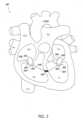
一部の実施形態では、二重心臓弁係留システムは、中隔に係留される三尖弁修理部および僧帽弁修理部を備え得る。図10は、三尖弁修理部700と僧帽弁修理部800とを備える二重心臓弁係留システム170の例の概略図である。三尖弁修理部700と僧帽弁修理部800とは、互いと結合でき、中隔に係留されるように構成され得る。例えば、三尖弁修理部700と僧帽弁修理部800とは、中隔横断開口に位置決めされるように構成される係留部500に結合され得る。三尖弁修理部700は、中隔横断開口に位置決めされる係留部500に自然三尖弁の弁葉を結合するように構成される複数の連結器710を備え得る。各々の連結器710の第1の遠位部分712が自然三尖弁の弁葉に結合でき、第2の遠位部分714が係留部500に結合できる。僧帽弁修理部800は、中隔横断開口に位置決めされる係留部500に自然僧帽弁の弁葉を結合するように構成される複数の連結器810を備え得る。例えば、各々の連結器810の第1の遠位部分814が自然僧帽弁の弁葉に結合でき、第2の遠位部分812が係留部500に結合できる。図10は、三尖弁修理部700が2つの連結器710を備えることができ、僧帽弁修理部800が2つの連結器810を備えることができることを示しているが、より多くの連結器710、810またはより少ない連結器710、810が使用できることは、理解されるべきである。In some embodiments, the dual heart valve anchoring system may include a tricuspid valve repair portion and a mitral valve repair portion anchored to the septum. FIG. 10 is a schematic diagram of an example of a dual heart
一部の実施形態では、連結器710と連結器810とは1つの連結器とでき、それによって1つの連結器は、係留部500を通じて延び、自然三尖弁の弁葉と自然僧帽弁の弁葉とを互いに結合するように構成される。例えば、複数の連結器710の各々と、複数の連結器810のうちの対応するものとは、同じ連結器であり得る。一部の実施形態では、複数の連結器710および複数の連結器810のいずれも同じ連結器ではない。In some embodiments,
一部の実施形態では、二重心臓弁係留システムは心臓弁置換部と心臓弁修理部とを備え得る。例えば、二重心臓弁係留システムは三尖弁置換部と僧帽弁修理部とを備え得る。代替で、二重心臓弁係留システムは三尖弁修理部と僧帽弁置換部とを備え得る。In some embodiments, the dual heart valve anchoring system may include a heart valve replacement portion and a heart valve repair portion. For example, the dual heart valve anchoring system may include a tricuspid valve replacement portion and a mitral valve repair portion. Alternatively, the dual heart valve anchoring system may include a tricuspid valve repair portion and a mitral valve replacement portion.
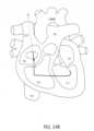
図11は、中隔を介して互いに結合される三尖弁置換部200および僧帽弁修理部800を備える二重心臓弁係留システム180の例の概略図である。三尖弁置換部200と僧帽弁修理部800とは、中隔横断開口に位置決めされるように構成される係留部500に結合され得る。僧帽弁修理部800は、自然僧帽弁の弁葉を係留部500に結合するように構成される連結器810を備え得る。連結器900が三尖弁置換部200を係留部500に結合することができる。例えば、連結器900の第1の端902が、三尖弁置換部200の第2の遠位端204など、三尖弁置換部200に結合され得る。連結器900の第2の端904が係留部500に結合され得る。11 is a schematic diagram of an example of a dual heart
図12を参照すると、三尖弁置換部1000の例と僧帽弁置換部1100の例とを備える二重心臓弁係留システム190の概略図が示されている。連結器400は、三尖弁置換部1000と僧帽弁置換部1100とを互いに結合させることができる。連結器400の対応する一部分は、中隔横断開口に位置決めされる係留部500を通じて延びることができる。Referring to FIG. 12, a schematic diagram of a dual heart
三尖弁置換部1000は、第1の遠位端1002と第2の遠位端1004とを備える三尖弁本体部分1006を備え得る。僧帽弁置換部1100は、第1の遠位端1102と第2の遠位端1104とを備える僧帽弁本体部分1106を備え得る。図12に示されているように、三尖弁置換部1000の第1の遠位端1002および僧帽弁置換部1100の第1の遠位端1102はそれぞれ右心房および左心房に向けて配向され得る。第2の遠位端1004、1104はそれぞれ右心室および左心室に向けて配向され得る。三尖弁置換部1000はフレーム1008と弁組織1010とを備え得る。僧帽弁置換部1100はフレーム1108と弁組織1110とを備え得る。一部の実施形態では、連結器400の第1の部分402は三尖弁置換部1000の第2の遠位端1004に結合され、連結器400の第2の部分404は僧帽弁置換部1100の第2の遠位端1104に結合され得る。一部の実施形態では、連結器400は、三尖弁置換部1000および僧帽弁置換部1100のフレーム1008、1108に、それぞれの第2の遠位端1004、1104において結合され得る。例えば、フレーム1008、1108は、それらへの連結器400の取り付けを容易にするために1つまたは複数の特徴部を備え得る。The
一部の実施形態では、二重心臓弁係留システム190は、本明細書に記載されているような1つまたは複数の他の特徴部を備え得る。一部の実施形態では、二重心臓弁係留システム190は複数の連結器400を備え得る。一部の実施形態では、二重心臓弁係留システム190は1つまたは複数の調整可能連結器420を備え得る。一部の実施形態では、二重心臓弁係留システム190は、剛体または半剛体の一部分436を備える連結器430のうちの1つまたは複数を備え得る。一部の実施形態では、二重心臓弁係留システム190は、係留部500ではなく係留部550を備え得る。In some embodiments, the dual heart
一部の実施形態では、本明細書に記載されている1つまたは複数の心臓弁置換部は、1つまたは複数の商業的に利用可能な心臓弁置換部(例えば、Edwards Lifesciences LLC、Irvine、CAから市販されているSapien 3(商標)、CardiAQ(商標)、およびCentera(商標))であり得る。一部の実施形態では、本明細書に記載されている二重心臓弁係留システムのうちの1つまたは複数は、係留部を備えなくてもよい。例えば、図5A、図6、図7A、図8、図9、図10、図11、および図12を参照して記載されている連結器は、係留部を通じて延びることなく中隔横断開口を通じて延びてもよい。In some embodiments, one or more of the heart valve replacements described herein may be one or more commercially available heart valve replacements (e.g.,
二重心臓弁係留システムをその標的部位において位置決めするための処置は、二重心臓弁係留システム送達カテーテルを同じ経路または同様の経路に沿って挿入および後退させることを含み得る。中隔に係留される三尖弁置換部および僧帽弁置換部の両方を展開するために送達カテーテルの挿入と後退との両方のために1つの経路を使用することは、例えば、より簡単な低侵襲経カテーテルの手法を可能にすることができ、患者への外傷を低減することができ、および/または、向上した患者の回復過程を容易にすることができる。A procedure for positioning the dual heart valve anchoring system at its target site may include inserting and retracting the dual heart valve anchoring system delivery catheter along the same or similar pathways. Using one pathway for both inserting and retracting the delivery catheter to deploy both the septally anchored tricuspid valve replacement and the mitral valve replacement may, for example, enable a simpler, less invasive transcatheter approach, reduce trauma to the patient, and/or facilitate an improved patient recovery process.
図13Aおよび図13Bは、二重心臓弁係留システムをその標的部位に位置決めするために、二重心臓弁係留システムを担持する送達カテーテルが沿って前進および後退させられ得る経路の例を示す概略図である。二重心臓弁係留システムは、本明細書に記載されている1つまたは複数の特徴部を有し得る(例えば、二重心臓弁係留システム100、110、120、130、140、150、190)。例えば、二重心臓弁係留システムは、三尖弁置換部と、僧帽弁置換部と、三尖弁置換部と僧帽弁置換部とを互いと結合する連結器とを備え得る。連結器は、中隔横断開口に位置決めされる係留部を通じて延びることができる。図13Aは、送達カテーテルが挿入されるのに沿う経路を示しており、図13Bは、送達カテーテルが後退させられるのに沿う経路を示している。13A and 13B are schematic diagrams illustrating examples of paths along which a delivery catheter carrying a dual heart valve anchoring system may be advanced and retracted to position the dual heart valve anchoring system at its target site. The dual heart valve anchoring system may have one or more features described herein (e.g., dual heart
図13Aを参照すると、二重心臓弁係留システムを担持する送達カテーテルは、下大静脈(IVC)を通じて前進させることができる。例えば、経大腿の手法が使用でき、大腿静脈を通じて送達カテーテルを下大静脈へ挿入する。送達カテーテルの遠位端が下大静脈から右心房(RA)へと延ばされ得る。次に、送達カテーテルの遠位端は、自然三尖弁によって形成された開口を通じて挿入され、右心房から右心室(RV)へと前進させられ得る。続いて、送達カテーテルは、右心室から、中隔に形成された中隔横断開口を介して、左心室(LV)へと延ばされ得る。送達カテーテルが左心室へと挿入された後、送達カテーテルの遠位端は、僧帽弁置換部のための標的部位に位置決めでき、僧帽弁置換部はその標的位置において展開され得る。With reference to FIG. 13A, a delivery catheter carrying the dual heart valve anchoring system can be advanced through the inferior vena cava (IVC). For example, a transfemoral approach can be used, inserting the delivery catheter into the inferior vena cava through the femoral vein. The distal end of the delivery catheter can be extended from the inferior vena cava into the right atrium (RA). The distal end of the delivery catheter can then be inserted through an opening formed by the native tricuspid valve and advanced from the right atrium into the right ventricle (RV). The delivery catheter can then be extended from the right ventricle through a transseptal opening formed in the septum into the left ventricle (LV). After the delivery catheter is inserted into the left ventricle, the distal end of the delivery catheter can be positioned at a target site for the mitral valve replacement, and the mitral valve replacement can be deployed at the target location.
図13Bを参照すると、僧帽弁置換部がその標的部位に位置決めされた後、送達カテーテルは右心室に向けて後退させられ得る。送達カテーテルは、送達カテーテルが前進させられたときに沿ったのと同じまたは実質的に同じ経路に沿って後退させられ得る。送達カテーテルが左心室を通じて右心室に向けて後退させられるとき、連結器の対応する部分が、左心室において送達カテーテルの遠位端から解放され得る。次に、送達カテーテルの遠位端は左心室から中隔横断開口を通じて右心室(RV)へと戻るように引き込まれ、係留部をその標的部位に残すことができる。係留部の少なくとも一部分と、連結器の対応する一部分とは、送達カテーテルが中隔横断開口を通じて戻るように移動させられるとき、中隔横断開口において位置決めされ得る。続いて、連結器の対応する一部分は、送達カテーテルの遠位端が右心室を通じて右心房に向けて後退させられるとき、右心室において解放させることができる。次に、送達カテーテルの遠位端は、三尖弁置換部のための所望の場所において位置決めされ得る。送達カテーテルの遠位端を三尖弁置換部のための所望の場所に位置決めした後、三尖弁置換部はその標的部位において展開され得る。次に、送達カテーテルは右心房へと引き込むことができ、下大静脈を通じて除去され得る。With reference to FIG. 13B, after the mitral valve replacement is positioned at its target site, the delivery catheter can be retracted toward the right ventricle. The delivery catheter can be retracted along the same or substantially the same path along which the delivery catheter was advanced. As the delivery catheter is retracted through the left ventricle toward the right ventricle, a corresponding portion of the coupler can be released from the distal end of the delivery catheter in the left ventricle. The distal end of the delivery catheter can then be retracted back from the left ventricle through the transseptal opening into the right ventricle (RV), leaving the tether at its target site. At least a portion of the tether and a corresponding portion of the coupler can be positioned at the transseptal opening as the delivery catheter is moved back through the transseptal opening. The corresponding portion of the coupler can then be released in the right ventricle as the distal end of the delivery catheter is retracted through the right ventricle toward the right atrium. The distal end of the delivery catheter can then be positioned at the desired location for the tricuspid valve replacement. After positioning the distal end of the delivery catheter at the desired location for the tricuspid valve replacement, the tricuspid valve replacement may be deployed at its target site. The delivery catheter may then be retracted into the right atrium and removed through the inferior vena cava.
図14Aおよび図14Bは、二重心臓弁係留システムをその標的部位に位置決めするために、二重心臓弁係留システムを担持する送達カテーテルが沿って前進および後退させられ得る経路の他の例を示す概略図である。二重心臓弁係留システムは、三尖弁置換部と僧帽弁置換部とを結合する連結器、および係留部を通じて延びる連結器など、本明細書に記載されている1つまたは複数の特徴部を有し得る(例えば、二重心臓弁係留システム100、110、120、130、140、150、190)。図14Aは、送達カテーテルが挿入され得るのに沿う経路を示しており、図14Bは、送達カテーテルが後退させられ得るのに沿う経路を示している。14A and 14B are schematic diagrams illustrating other examples of paths along which a delivery catheter carrying a dual heart valve anchoring system may be advanced and retracted to position the dual heart valve anchoring system at its target site. The dual heart valve anchoring system may have one or more features described herein, such as a coupler connecting the tricuspid and mitral valve replacement portions and a coupler extending through the anchoring portions (e.g., dual heart
図14Aを参照すると、二重心臓弁係留システムを担持する送達カテーテルは、上大静脈(SVC)を通じて前進させることができる。例えば、経鎖骨下または経頸部の手法が使用でき、鎖骨下静脈または頸静脈を通じて送達カテーテルを上大静脈へ挿入する。送達カテーテルの遠位端は、上大静脈から右心房(RA)へと延ばすことができ、次に、右心房から、自然三尖弁によって形成された開口を通じて、右心室(RV)へと延ばすことができる。続いて、送達カテーテルは、右心室から、中隔に形成された中隔横断開口を介して、左心室(LV)へと延ばされ得る。送達カテーテルが左心室へと挿入された後、送達カテーテルの遠位端は、僧帽弁置換部のための標的部位に位置決めされ得る。次に、僧帽弁置換部はその標的位置で展開され得る。With reference to FIG. 14A, a delivery catheter carrying the dual heart valve anchoring system can be advanced through the superior vena cava (SVC). For example, a transclavian or transjugular approach can be used, inserting the delivery catheter into the superior vena cava through the subclavian or jugular vein. The distal end of the delivery catheter can be extended from the superior vena cava into the right atrium (RA), and then from the right atrium through an opening formed by the native tricuspid valve into the right ventricle (RV). The delivery catheter can then be extended from the right ventricle through a transseptal opening formed in the septum into the left ventricle (LV). After the delivery catheter is inserted into the left ventricle, the distal end of the delivery catheter can be positioned at a target site for the mitral valve replacement. The mitral valve replacement can then be deployed at the target location.
図14Bを参照すると、僧帽弁置換部の展開の後、送達カテーテルは右心室に向けて後退させられ得る。送達カテーテルは、送達カテーテルが前進させられたときに沿ったのと同じまたは実質的に同じ経路に沿って後退させられ得る。送達カテーテルが左心室を通じて右心室に向けて後退させられるとき、連結器の対応する部分が、左心室において送達カテーテルの遠位端から解放され得る。次に、送達カテーテルの遠位端は中隔横断開口を通じて右心室(RV)へと戻るように引き込まれ得る。係留部は、連結器の対応する一部分と共に、中隔横断開口における標的部位において解放できる。続いて、連結器の対応する一部分は、送達カテーテルの遠位端が右心室を通じて右心房に向けて後退させられるとき、右心室において解放され得る。次に、送達カテーテルの遠位端は、三尖弁置換部のための所望の場所において位置決めでき、三尖弁置換部は展開され得る。次に、送達カテーテルは右心房へと引き込むことができ、上大静脈を通じて除去され得る。With reference to FIG. 14B, after deployment of the mitral valve replacement, the delivery catheter can be retracted toward the right ventricle. The delivery catheter can be retracted along the same or substantially the same path along which the delivery catheter was advanced. As the delivery catheter is retracted through the left ventricle toward the right ventricle, a corresponding portion of the coupler can be released from the distal end of the delivery catheter in the left ventricle. The distal end of the delivery catheter can then be retracted back into the right ventricle (RV) through the transseptal opening. The tether can be released at the target site in the transseptal opening along with a corresponding portion of the coupler. The corresponding portion of the coupler can then be released in the right ventricle as the distal end of the delivery catheter is retracted through the right ventricle toward the right atrium. The distal end of the delivery catheter can then be positioned at the desired location for the tricuspid valve replacement, and the tricuspid valve replacement can be deployed. The delivery catheter can then be retracted into the right atrium and removed through the superior vena cava.
図15は、二重心臓弁係留システムをその標的部位として位置決めするための埋込処置1500の例を示す流れ図である。二重心臓弁係留システムは送達カテーテルによって運ぶことができる。二重心臓弁係留システムは、例えば、三尖弁置換部と僧帽弁置換部とを結合する連結器を備える、本明細書に記載されている1つまたは複数の特徴部を有し得る(例えば、二重心臓弁係留システム100、110、120、130、140、150、190)。一部の実施形態では、二重心臓弁係留システムは、連結器が係留部を通じて延びるように係留部を備える。一部の実施形態では、二重心臓弁係留システムは係留部を備えない。FIG. 15 is a flow diagram illustrating an example of an
図15を参照すると、ブロック1502において、送達カテーテルは下大静脈または上大静脈を通じて右心房へと導入され得る。ブロック1504において、送達カテーテルは、右心房から自然三尖弁によって形成された開口を通じて右心室へと前進させられ得る。送達カテーテルは右心室を通じて左心室に向けて前進させられ得る。ブロック1506において、送達カテーテルは、送達カテーテルを右心室から左心室へと挿入するために、心室中隔における中隔横断開口を通じて通り抜けさせられ得る。一部の実施形態では、中隔横断開口はあらかじめ形成でき、例えば、上大静脈または下大静脈への送達カテーテルの挿入の前に形成される。一部の実施形態では、中隔横断開口は、送達カテーテルによって同じく担持される1つまたは複数の器具によって形成され得る。例えば、中隔横断開口は、中隔への送達カテーテルの前進の間に形成できる。Referring to FIG. 15, in
中隔横断開口を通じて移動した後、送達カテーテルは自然僧帽弁に向けて左心室を通じて前進させられ得る。ブロック1508において、送達カテーテルの遠位端を、僧帽弁置換部のための標的部位において位置決めされ得る。ブロック1510において、僧帽弁置換部はその標的部位において解放され得る。僧帽弁置換部は、送達カテーテルの遠位端から展開でき、自然僧帽弁において所望の位置に位置決めできる。After moving through the transseptal opening, the delivery catheter may be advanced through the left ventricle toward the native mitral valve. In
僧帽弁置換部の解放の後、送達カテーテルは、前進させられたときに沿った経路と同じまたは実質的に同じ経路に沿って後退させられ得る。ブロック1512では、送達カテーテルは、左心室、中隔横断開口を通じて右心室へと後退させられ得る。ブロック1514では、連結器のそれぞれの一部分は、送達カテーテルを、左心室、中隔横断開口を通じて右心室へと後退させる間に、左心室、中隔横断開口、および右心室において解放させられ得る。After release of the mitral valve replacement, the delivery catheter may be retracted along the same or substantially the same path along which it was advanced. In
本明細書において記載されているように、一部の実施形態では、二重心臓弁係留システムは係留部を備え得る。係留部は、三尖弁置換部と僧帽弁置換部との間にあり、連結器に結合され得る。一部の実施形態では、連結器は係留部の開口を通じて延び得る。係留部の少なくとも一部分と、連結器の対応する一部分とは、中隔横断開口を通じた送達カテーテルの後退の間、中隔横断開口において展開され得る。係留部は、中隔横断開口の封止を容易にするように構成された閉塞器を備え得る。例えば、中隔横断開口において係留部の少なくとも一部分と連結器の対応する部分とを解放することは、中隔横断開口を封止することを含み得る。一部の実施形態では、中隔横断開口は、それを通じて通り抜けさせられる連結器の対応する一部分を備える係留部がその標的部位において位置決めされると、封止され得る。As described herein, in some embodiments, the dual heart valve anchoring system may include an anchor portion. The anchor portion may be between the tricuspid valve replacement portion and the mitral valve replacement portion and may be coupled to a coupler. In some embodiments, the coupler may extend through an opening in the anchor portion. At least a portion of the anchor portion and a corresponding portion of the coupler may be deployed at the transseptal opening during retraction of the delivery catheter through the transseptal opening. The anchor portion may include an occluder configured to facilitate sealing of the transseptal opening. For example, releasing at least a portion of the anchor portion and a corresponding portion of the coupler at the transseptal opening may include sealing the transseptal opening. In some embodiments, the transseptal opening may be sealed when the anchor portion is positioned at its target site with the corresponding portion of the coupler threaded therethrough.
送達カテーテルは右心室を通じて右心房に向けて戻るように引き込まれ得る。ブロック1516では、送達カテーテルの遠位端は、送達カテーテルを右心室へと後退させた後、三尖弁置換部のための標的部位に位置決めされ得る。ブロック1518において、三尖弁置換部はその標的部位において解放され得る。送達カテーテルは、右心房を通じて引き込まれ、続いて、上大静脈または下大静脈などを介して、送達カテーテルを前進させるときに使用されたのと同じ経路に沿って心臓から除去される。The delivery catheter may be retracted back through the right ventricle toward the right atrium. In block 1516, the distal end of the delivery catheter may be positioned at the target site for the tricuspid valve replacement after retracting the delivery catheter into the right ventricle. In
本明細書において記載されているように、一部の実施形態では、二重心臓弁係留システムは複数の連結器を備え得る。例えば、二重心臓弁係留システムは、第2の連結器など、三尖弁置換部と僧帽弁置換部とを互いに結合する1つまたは複数の追加の連結器を備え得る。左心室、中隔横断開口を通じて右心室へと送達カテーテルを後退させることは、左心室、中隔横断開口、および右心室において両方の連結器のそれぞれの一部分を解放することを含み得る。一部の実施形態では、二重心臓弁係留システムは、中隔横断開口に位置決めされるように構成される一部分を少なくとも備える係留部を備え得る。一部の実施形態では、両方の連結器が係留部を通じて延び得る。左心室、中隔横断開口を通じて右心室へと送達カテーテルを後退させることは、左心室、中隔横断開口、および右心室において両方の連結器のそれぞれの一部分を解放することと、係留部を中隔横断開口における標的位置に配置することとを含み得る。As described herein, in some embodiments, the dual heart valve anchoring system may include multiple connectors. For example, the dual heart valve anchoring system may include one or more additional connectors, such as a second connector, that couple the tricuspid valve replacement and the mitral valve replacement to each other. Retracting the delivery catheter through the left ventricle, the transseptal opening, and the right ventricle may include releasing a respective portion of both connectors in the left ventricle, the transseptal opening, and the right ventricle. In some embodiments, the dual heart valve anchoring system may include an anchoring portion that includes at least a portion configured to be positioned in the transseptal opening. In some embodiments, both connectors may extend through the anchoring portion. Retracting the delivery catheter through the left ventricle, the transseptal opening, and the right ventricle may include releasing a respective portion of both connectors in the left ventricle, the transseptal opening, and the right ventricle, and placing the anchoring portion at a target location in the transseptal opening.
一部の実施形態では、連結器は調整可能な長さを備え得る。連結器の長さは、個人の生体構造に応じてなど、埋込処置の間に調整され得る。一部の実施形態では、1つまたは複数の撮像技術が、連結器の適切な長さを決定するときに処置の間に用いられ得る。一部の実施形態では、埋込処置は、経食道(TEE)、心エコー検査、経胸壁心エコー検査(TTE)、および心臓内心エコー検査(ICE)のうちの1つまたは複数の案内の下で実施され得る。他の知られている可視化技術が追加または代替で用いられてもよい。In some embodiments, the coupler may comprise an adjustable length. The length of the coupler may be adjusted during the implantation procedure, such as depending on the individual's anatomy. In some embodiments, one or more imaging techniques may be used during the procedure when determining the appropriate length of the coupler. In some embodiments, the implantation procedure may be performed under the guidance of one or more of transesophageal (TEE), echocardiography, transthoracic echocardiography (TTE), and intracardiac echocardiography (ICE). Other known visualization techniques may be used in addition or instead.
二重心臓弁係留システムの1つまたは複数の連結器の長さは、患者への1つまたは複数の連結器の挿入の後、1つまたは複数の撮像技術の助けで調整され得る。1つまたは複数の連結器の長さは、中隔への所望の係留を提供するように、個人の生体構造に基づいて選択され得る。一部の実施形態では、連結器の長さは、連結器が心室収縮の間にピンと張られるように調整され得る。The length of the coupler or couplers of the dual heart valve anchoring system may be adjusted with the aid of one or more imaging techniques after insertion of the coupler or couplers into the patient. The length of the coupler or couplers may be selected based on the individual's anatomy to provide the desired anchoring to the septum. In some embodiments, the length of the coupler may be adjusted such that the coupler is taut during ventricular contraction.
一部の実施形態では、1つまたは複数の連結器の長さは、送達カテーテルを上大静脈または下大静脈へと導入した後に調整され得る。一部の実施形態では、1つまたは複数の連結器の長さは、すべての置換弁がそれぞれの標的部位に位置決めされた後に調整され得る。例えば、1つまたは複数の連結器の長さは、三尖弁置換部がその所望の位置に配置された後に調整され得る。一部の実施形態では、1つまたは複数の連結器の長さは複数回にわたって調整できる。例えば、連結器の長さは、僧帽弁置換部、係留部、および三尖弁置換部をそれらのそれぞれの標的場所において1回または複数回にわたって位置決めした後に調整できる。一部の実施形態では、連結器の長さは、その対応する一部分のうちの1つまたは複数が送達カテーテルから解放された後に調整され得る。例えば、連結器の長さは、僧帽弁置換部の展開の後で係留部の展開の前(例えば、連結器の対応する一部分が左心室において解放された後)、係留部の展開の後で送達カテーテルのさらなる後退の前、係留部の展開の後で三尖弁置換部の展開の前(例えば、連結器の対応する一部分が右心室において解放された後)、三尖弁置換部の展開の後のうちの1つまたは複数において調整され得る。一部の実施形態では、連結器の長さは、その対応する一部分の各々が送達カテーテルから解放された後に調整され得る。In some embodiments, the length of the one or more connectors may be adjusted after introducing the delivery catheter into the superior or inferior vena cava. In some embodiments, the length of the one or more connectors may be adjusted after all replacement valves are positioned at their respective target sites. For example, the length of the one or more connectors may be adjusted after the tricuspid valve replacement is placed in its desired location. In some embodiments, the length of the one or more connectors may be adjusted multiple times. For example, the length of the connectors may be adjusted after positioning the mitral valve replacement, the anchoring portion, and the tricuspid valve replacement at their respective target locations one or more times. In some embodiments, the length of the connectors may be adjusted after one or more of its corresponding portions are released from the delivery catheter. For example, the length of the coupler may be adjusted after deployment of the mitral valve replacement and before deployment of the tether (e.g., after the corresponding portion of the coupler is released in the left ventricle), after deployment of the tether and before further retraction of the delivery catheter, after deployment of the tether and before deployment of the tricuspid valve replacement (e.g., after the corresponding portion of the coupler is released in the right ventricle), or after deployment of the tricuspid valve replacement. In some embodiments, the length of the coupler may be adjusted after each of its corresponding portions is released from the delivery catheter.
係止機構が、適切な長さが埋込処置の間に決定された後、選択された長さにおいて連結器を固定するために、展開、作動、および/または起動させられ得る。一部の実施形態では、係止機構は、各々の調整の後に展開、作動、および/または起動させられ得る。本明細書において記載されているように、一部の実施形態では、二重心臓弁係留システムは複数の係止機構を備え得る。一部の実施形態では、係止機構は、各々の一部分が解放および調整された後を含め、連結器の1つまたは複数の一部分が開放および調整された後に展開、作動、および/または起動させられ得る。The locking mechanism may be deployed, actuated, and/or activated to secure the coupler at the selected length after the appropriate length is determined during the implantation procedure. In some embodiments, the locking mechanism may be deployed, actuated, and/or activated after each adjustment. As described herein, in some embodiments, the dual heart valve anchoring system may include multiple locking mechanisms. In some embodiments, the locking mechanism may be deployed, actuated, and/or activated after one or more portions of the coupler are released and adjusted, including after each portion is released and adjusted.
追加の実施形態
実施形態に応じて、本明細書に記載されている過程またはアルゴリズムのいずれかの特定の作用、成果、または機能が、異なる順序で実施され得る、追加され得る、融合され得る、または除外され得る。したがって、特定の実施形態では、すべての記載された作用および事象が過程の実施のために必要とは限らない。Depending on the embodiment, certain acts, results, or functions of any of the processes or algorithms described herein may be performed in a different order, added, combined, or removed. Thus, in a particular embodiment, not all described acts and events are required to implement a process.
特には「~できる」、「~得る」、「~する可能性がある」、「~してもよい」、「例えば」などの本明細書で使用されている条件の言葉は、他に明示的に述べられていない場合、または、使用されているような文脈の中で他に理解できない場合、その元の意味において意図されており、特定の実施形態が、他の実施形態は含まなくとも、特定の特徴、要素、および/またはステップを含むことを伝えるように概して意図されている。したがって、このような条件の言葉は、特徴、要素、および/もしくはステップがどんな形であっても1つもしくは複数の実施形態のために必要とされること、または、1つもしくは複数の実施形態が、これらの特徴、要素、および/またはステップが任意の特定の実施形態に含まれるかどうか、もしくは任意の特定の実施形態で実施されるかどうかを、作者の入力もしくは動機付けがあろうがなかろうが決定するための論理を必ず含むことを意味するようには概して意図されていない。「備える」、「含む」、「有する」などの用語は同義語であり、通常の意味において使用され、包括的に、オープンエンドの様式で使用されており、追加の要素、特徴、作用、動作などを排除しない。また、「または」という用語は、例えば要素の列記を繋ぐために使用されるとき、列記における要素のうちの1つ、一部、または全部を意味するように、その包括的な意味において(排他的な意味においてではなく)使用されている。「X、Y、およびZのうちの少なくとも1つ」という文言などの接続語は、他に明示的に述べられていない場合、品目、用語、要素などがX、Y、またはZのいずれかであり得ることを伝えるために、概して使用されているような文脈で理解されるものである。したがって、このような接続語は、特定の実施形態がXのうちの少なくとも1つ、Yのうちの少なくとも1つ、およびZのうちの少なくとも1つを各々存在させるために必要とすることを意味するようには概して意図されていない。In particular, conditional words used herein such as "can," "may," "could," "may," "for example," and the like, unless otherwise expressly stated or otherwise understood in the context as used, are intended in their original sense and are generally intended to convey that a particular embodiment includes certain features, elements, and/or steps while other embodiments do not. Thus, such conditional words are generally not intended to imply that the features, elements, and/or steps are in any way required for one or more embodiments, or that one or more embodiments necessarily include logic for determining, with or without author input or motivation, whether those features, elements, and/or steps are included in or performed in any particular embodiment. Terms such as "comprise," "include," "have," and the like are synonymous and are used in their ordinary sense, inclusively, in an open-ended manner, and do not exclude additional elements, features, acts, operations, and the like. Also, the term "or," for example, when used to join a list of elements, is used in its inclusive sense (not its exclusive sense) to mean one, some, or all of the elements in the list. Conjunctions such as "at least one of X, Y, and Z" are to be understood in the context as they are generally used to convey that an item, term, element, etc., can be either X, Y, or Z, unless expressly stated otherwise. Thus, such conjunctive terms are generally not intended to imply that a particular embodiment requires at least one of X, at least one of Y, and at least one of Z to each be present.
実施形態の先の記載において、様々な特徴が、本開示を合理化する目的、および、様々な発明の態様のうちの1つまたは複数の理解を助ける目的のために、単一の実施形態、図、またはそれらの記載において一緒に組み合わされていることもあったことは、理解されるべきである。しかしながら、この開示の方法は、任意の請求がその請求において明示的に提唱されているものより多くの特徴を要求するという意図を反映するとして解釈されるものではない。さらに、本明細書における具体的な実施形態において図示および/または記載されている任意の構成要素、特徴、またはステップは、任意の他の実施形態に適用できる、または任意の他の実施形態と共に使用できる。さらに、構成要素、特徴、またはステップのうちの構成要素、特徴、ステップの群は、各々の実施形態について必要ではなく、または必須ではない。したがって、本明細書で開示されており、後で請求されている本発明の範囲が、前述した具体的な実施形態によって限定されるべきではなく、後に続く請求項の公平な読解のみによって決定されるべきであることが、意図されている。It should be understood that in the preceding description of the embodiments, various features may have been combined together in a single embodiment, figure, or description thereof for the purpose of streamlining the disclosure and aiding in the understanding of one or more of the various inventive aspects. However, this method of disclosure is not to be interpreted as reflecting an intention that any claim requires more features than are expressly set forth in that claim. Moreover, any component, feature, or step illustrated and/or described in a specific embodiment herein may be applied to or used with any other embodiment. Moreover, groups of components, features, or steps among the components, features, or steps are not necessary or essential for each embodiment. Thus, it is intended that the scope of the inventions disclosed herein and later claimed should not be limited by the specific embodiments described above, but should be determined solely by a fair reading of the claims that follow.
特定の序数の用語(例えば、「第1の」または「第2の」)が参照の容易さのために提供され得るが、物理的な特徴または順位を必ずしも意味しないことは、理解されるべきである。そのため、本明細書で使用されているように、構造、構成要素、動作などの要素を変更するために使用される序数の用語(例えば、「第1の」、「第2の」、「第3の」など)は、要素の任意の他の要素に対する優先順位または順番を必ずしも指示せず、むしろ、要素を、同様または同一の名前を有する他の要素から(序数の用語の使用のために)概して区別することができる。また、本明細書で使用されているように、不定冠詞(「ある(a、an)」)は、「1つ」ではなく「1つまたは複数」を指示してもよい。さらに、条件または事象「に基づいて」実施される動作は、明示的に提唱されていない1つまたは複数の他の条件または事象に基づいて実施されてもよい。It should be understood that certain ordinal terms (e.g., "first" or "second") may be provided for ease of reference, but do not necessarily imply physical characteristics or ranking. Thus, as used herein, ordinal terms (e.g., "first," "second," "third," etc.) used to modify elements, such as structures, components, operations, etc., do not necessarily indicate a priority or order of the element relative to any other elements, but rather, may generally distinguish the element (because of the use of ordinal terms) from other elements having similar or identical names. Also, as used herein, the indefinite article ("a, an") may indicate "one or more" rather than "one." Furthermore, an action that is performed "based on" a condition or event may be performed based on one or more other conditions or events not expressly proposed.
他に定められていない場合、本明細書で使用されているすべての用語(技術的な用語および科学的な用語を含む)は、例示的な実施形態が属する技術における当業者によって一般的に理解されるのと同じ意味を有する。一般的に使用される辞書に定められているものなどの用語が、関連する技術の背景におけるそれらの意味と一致する意味を有するとして解釈されるべきであり、本明細書において明示的に定められていない場合、理想的または過度に形式的な意味において解釈されるべきではないことは、さらに理解されるものである。Unless otherwise specified, all terms (including technical and scientific terms) used herein have the same meaning as commonly understood by one of ordinary skill in the art to which the exemplary embodiments belong. It is further understood that terms such as those defined in commonly used dictionaries should be interpreted as having a meaning consistent with their meaning in the context of the relevant technology, and should not be interpreted in an idealized or overly formal sense unless expressly defined herein.
「外側」、「内側」、「上方」、「下方」、「~の下方」、「~の上方」、「鉛直」、「水平」、および同様の用語といった空間的に相対的な用語は、ある要素または構成要素と他の要素または構成要素との間の関係を、図面に示されているように記載するために、記載の容易性のために本明細書において使用され得る。空間的に相対的な用語が、図面において描写されている配向に加えて、使用中または動作中の装置の異なる配向を網羅するように意図されていることは、理解されるべきである。例えば、図面に示されている装置がひっくり返されている場合、他の装置「の下方」または「の下」に位置決めされた装置は、他の装置「の上方」に配置され得る。したがって、「~の下方」という図示の用語は、下方の位置と上方の位置との両方を含む可能性がある。装置は他の方向で配向されてもよく、したがって、空間的に相対的な用語は配向に応じて異なって解釈され得る。Spatially relative terms such as "outside," "inside," "up," "down," "down of," "above," "vertical," "horizontal," and similar terms may be used herein for ease of description to describe the relationship between one element or component and another element or component as shown in the drawings. It should be understood that the spatially relative terms are intended to encompass different orientations of the device in use or operation in addition to the orientation depicted in the drawings. For example, if the device shown in the drawings is turned upside down, a device positioned "down" or "below" another device may be positioned "above" the other device. Thus, the illustrated term "down" can include both a below position and an above position. Devices may be oriented in other directions, and thus the spatially relative terms may be interpreted differently depending on the orientation.
他に明示的に述べられていない場合、「より少ない」、「より多い」、「より大きい」などの比較および/または量の用語は、同等の概念を網羅するように意図されている。例えば、「より少ない」は、厳密な機械的な意味における「より少ない」を意味するだけでなく、「より小さいかまたは等しい」も意味することができる。Unless expressly stated otherwise, comparison and/or quantity terms such as "less," "more," and "greater" are intended to cover equivalence concepts. For example, "less" can mean not only "less" in the strict mechanical sense, but also "less than or equal to."
1 心臓
2 左心房
3 左心室
4 右心室
5 右心房
6 僧帽弁
7 大動脈弁
8 三尖弁
9 肺動脈弁
10 中隔
11 肺動脈
12 大動脈
13 右肺動脈
14 左肺動脈
100、110、120、130、140、150、160、170、180、190 二重心臓弁係留システム
200 三尖弁置換部
202 第1の遠位端
204 第2の遠位端
206 三尖弁本体部分
300 僧帽弁置換部
302 第1の遠位端
304 第2の遠位端
400、410、420、430 連結器
402、412、422、432 第1の部分
404、414、424、434 第2の部分
416 中隔横断部分
420 調整可能連結器
436 剛体または半剛体の一部分
436a 第1の区分
436b 第2の区分
500、550 係留部
502 第1の中隔接触部
504 第2の中隔接触部
506 係留部本体
508 第1の中隔接触部502の第1の表面
510 第1の中隔接触部502の第2の表面
512 第2の中隔接触部504の第1の表面
514 第2の中隔接触部504の第2の表面
516 第1の遠位端
518 第2の遠位端
520 内腔
552 第1の遠位端
554 第2の遠位端
556 係留本体部分
556a 第1の剛体または半剛体の一部分
556b 第2の剛体または半剛体の一部分
560 内腔
562 第1の中隔接触部
564 第2の中隔接触部
600 係止機構
602 第1の移動可能フラップ
604 第2の移動可能フラップ
606 第3の移動可能フラップ
602a、604a、606a 第1の遠位部分
608 開口
700 三尖弁修理部
710 連結器
712 第1の遠位部分
714 第2の遠位部分
800 僧帽弁修理部
810 連結器
812 第2の遠位部分
814 第1の遠位部分
900 連結器
902 第1の端
904 第2の端
1000 三尖弁置換部
1002 第1の遠位端
1004 第2の遠位端
1006 三尖弁本体部分
1008 フレーム
1010 弁組織
1100 僧帽弁置換部
1102 第1の遠位端
1104 第2の遠位端
1106 僧帽弁本体部分
1008 フレーム
1110 弁組織 1. Heart
2. Left Atrium
3. Left Ventricle
4 Right Ventricle
5 Right Atrium
6. Mitral Valve
7. Aortic Valve
8 Tricuspid Valve
9 Pulmonary valve
10 Septum
11 Pulmonary artery
12 Aorta
13 Right pulmonary artery
14 Left pulmonary artery
100, 110, 120, 130, 140, 150, 160, 170, 180, 190 Dual Heart Valve Tethering System
200 Tricuspid valve replacement
202 first distal end
204 second distal end
206 Tricuspid valve body
300 Mitral valve replacement
302 first distal end
304 Second Distal End
400, 410, 420, 430 coupler
402, 412, 422, 432 First part
404, 414, 424, 434 Second part
416 Transverse septum
420 Adjustable Coupler
436 Part of a rigid or semi-rigid body
436a First division
436b Second division
500, 550 Moorings
502 First septal contact
504 Second septal contact
506 Mooring body
508 First surface of first
510 Second surface of first
512 a first surface of the second
514 Second surface of second
516 First Distal End
518 Second Distal End
520 Lumen
552 first distal end
554 Second Distal End
556 Mooring body part
556a A portion of a first rigid or semi-rigid body
556b Part of a second rigid or semi-rigid body
560 Lumen
562 First septal contact
564 Second septal contact
600 Locking mechanism
602 First Movable Flap
604 Second movable flap
606 Third Movable Flap
602a, 604a, 606a First distal portion
608 Opening
700 Tricuspid valve repair section
710 Coupler
712 First Distal Portion
714 Second Distal Part
800 Mitral Valve Repair Department
810 Coupler
812 Second Distal Part
814 First Distal Part
900 Coupler
902 First Edge
904 Second End
1000 Tricuspid valve replacement
1002 first distal end
1004 second distal end
1006 Tricuspid valve body part
1008 Frame
1010 Valve tissue
1100 Mitral valve replacement
1102 first distal end
1104 second distal end
1106 Mitral valve body
1008 Frame
1110 Valve tissue
Claims (21)
Translated fromJapanese前記心室中隔における第2の中隔横断開口の中に固定されるように構成される少なくとも一部分を備える第2の係留部と、
フレーム及び弁組織を備える三尖弁装置と、
フレーム及び弁組織を備える僧帽弁装置と、
前記三尖弁装置および前記僧帽弁装置を前記第1の係留部に結合するために前記第1の係留部の内腔を通じて延びる柔軟な第1の連結器と、
前記三尖弁装置および前記僧帽弁装置を前記第2の係留部に結合するために前記第2の係留部の内腔を通じて延びる柔軟な第2の連結器と、
を備える二重心臓弁係留システム。 a first anchoring portion having at least a portion configured to be secured within a first transseptal opening in the interventricular septum;
a second anchor portion having at least a portion configured to be secured within a second transseptal opening in the ventricular septum;
a tricuspid valve device comprising a frame and valve tissue;
a mitral valve apparatus comprising a frame and valve tissue;
a first flexible coupler extending through a lumen of the first anchor for coupling the tricuspid valve device and the mitral valve device to the first anchor;
a second flexible coupler extending through a lumen of the second anchor for coupling the tricuspid valve device and the mitral valve device to the second anchor;
1. A dual heart valve anchoring system comprising:
フレーム及び弁組織を備える僧帽弁置換部と、
前記三尖弁置換部と前記僧帽弁置換部とを結合する柔軟な第1の連結器であって、心室中隔における第1の中隔横断開口を通じて延びるように構成される柔軟な第1の連結器と、
前記三尖弁置換部と前記僧帽弁置換部とを結合する柔軟な第2の連結器であって、前記心室中隔における第2の中隔横断開口を通じて延びるように構成される柔軟な第2の連結器と、
を備える二重心臓弁係留システム。 a tricuspid valve replacement comprising a frame and valve tissue;
a mitral valve replacement comprising a frame and valve tissue;
a first flexible connector coupling the tricuspid valve replacement and the mitral valve replacement, the first flexible connector being configured to extend through a first transseptal opening in the ventricular septum;
a second flexible connector coupling the tricuspid valve replacement and the mitral valve replacement, the second flexible connector configured to extend through a second transseptal opening in the ventricular septum;
1. A dual heart valve anchoring system comprising:
Priority Applications (1)
| Application Number | Priority Date | Filing Date | Title |
|---|---|---|---|
| JP2025005540AJP2025065152A (en) | 2019-02-27 | 2025-01-15 | Double Heart Valve Tethering |
Applications Claiming Priority (3)
| Application Number | Priority Date | Filing Date | Title |
|---|---|---|---|
| US201962811453P | 2019-02-27 | 2019-02-27 | |
| US62/811,453 | 2019-02-27 | ||
| PCT/US2020/016928WO2020176208A1 (en) | 2019-02-27 | 2020-02-06 | Double heart valve anchoring |
Related Child Applications (1)
| Application Number | Title | Priority Date | Filing Date |
|---|---|---|---|
| JP2025005540ADivisionJP2025065152A (en) | 2019-02-27 | 2025-01-15 | Double Heart Valve Tethering |
Publications (2)
| Publication Number | Publication Date |
|---|---|
| JP2022522178A JP2022522178A (en) | 2022-04-14 |
| JP7621959B2true JP7621959B2 (en) | 2025-01-27 |
Family
ID=69771135
Family Applications (2)
| Application Number | Title | Priority Date | Filing Date |
|---|---|---|---|
| JP2021550041AActiveJP7621959B2 (en) | 2019-02-27 | 2020-02-06 | Double Heart Valve Tethering |
| JP2025005540APendingJP2025065152A (en) | 2019-02-27 | 2025-01-15 | Double Heart Valve Tethering |
Family Applications After (1)
| Application Number | Title | Priority Date | Filing Date |
|---|---|---|---|
| JP2025005540APendingJP2025065152A (en) | 2019-02-27 | 2025-01-15 | Double Heart Valve Tethering |
Country Status (5)
| Country | Link |
|---|---|
| US (1) | US20210378817A1 (en) |
| EP (1) | EP3930628B1 (en) |
| JP (2) | JP7621959B2 (en) |
| CN (2) | CN119606604A (en) |
| WO (1) | WO2020176208A1 (en) |
Families Citing this family (15)
| Publication number | Priority date | Publication date | Assignee | Title |
|---|---|---|---|---|
| US20090276040A1 (en) | 2008-05-01 | 2009-11-05 | Edwards Lifesciences Corporation | Device and method for replacing mitral valve |
| CA2961053C (en) | 2009-04-15 | 2019-04-30 | Edwards Lifesciences Cardiaq Llc | Vascular implant and delivery system |
| NZ596179A (en) | 2009-04-29 | 2014-05-30 | Cleveland Clinic Foundation | Apparatus and method for replacing a diseased cardiac valve |
| US8652203B2 (en) | 2010-09-23 | 2014-02-18 | Cardiaq Valve Technologies, Inc. | Replacement heart valves, delivery devices and methods |
| US8449599B2 (en) | 2009-12-04 | 2013-05-28 | Edwards Lifesciences Corporation | Prosthetic valve for replacing mitral valve |
| US8475525B2 (en)* | 2010-01-22 | 2013-07-02 | 4Tech Inc. | Tricuspid valve repair using tension |
| US9439763B2 (en) | 2013-02-04 | 2016-09-13 | Edwards Lifesciences Corporation | Prosthetic valve for replacing mitral valve |
| US20140277427A1 (en) | 2013-03-14 | 2014-09-18 | Cardiaq Valve Technologies, Inc. | Prosthesis for atraumatically grasping intralumenal tissue and methods of delivery |
| US9532870B2 (en) | 2014-06-06 | 2017-01-03 | Edwards Lifesciences Corporation | Prosthetic valve for replacing a mitral valve |
| KR20170066470A (en) | 2014-09-28 | 2017-06-14 | 카디오키네틱스 인크. | Apparatuses for treating cardiac dysfunction |
| US10531951B2 (en) | 2014-11-26 | 2020-01-14 | Edwards Lifesciences Corporation | Transcatheter prosthetic heart valve and delivery system |
| WO2016153918A1 (en) | 2015-03-20 | 2016-09-29 | Cardiokinetix, Inc. | Systems and methods for delivering an implantable device |
| ES2982566T3 (en) | 2019-04-23 | 2024-10-16 | Edwards Lifesciences Corp | Motorized implant delivery system |
| EP4247297A1 (en) | 2020-12-18 | 2023-09-27 | Edwards Lifesciences Corporation | Storage jar assembly for aprosthetic heart valve |
| JP2025514393A (en) | 2022-04-29 | 2025-05-02 | タンジェント カーディオバスキュラー, インコーポレイテッド | Percutaneous tricuspid valve repair devices and methods |
Citations (4)
| Publication number | Priority date | Publication date | Assignee | Title |
|---|---|---|---|---|
| JP2008536592A (en) | 2005-04-21 | 2008-09-11 | エドワーズ ライフサイエンシーズ アーゲー | Blood flow control device |
| US20130261738A1 (en) | 2012-03-28 | 2013-10-03 | Medtronic, Inc. | Dual Valve Prosthesis for Transcatheter Valve Implantation |
| WO2016108181A1 (en) | 2014-12-30 | 2016-07-07 | Tel Hashomer Medical Research, Infrastructure And Services Ltd. | Cardiac prostheses |
| JP2017148485A (en) | 2015-12-22 | 2017-08-31 | エヌヴィーティー アーゲー | Prosthetic mitral valve coaptation enhancement device |
Family Cites Families (8)
| Publication number | Priority date | Publication date | Assignee | Title |
|---|---|---|---|---|
| US7691144B2 (en)* | 2003-10-01 | 2010-04-06 | Mvrx, Inc. | Devices, systems, and methods for reshaping a heart valve annulus |
| US20070173926A1 (en)* | 2005-12-09 | 2007-07-26 | Bobo Donald E Jr | Anchoring system for medical implant |
| US20070203391A1 (en)* | 2006-02-24 | 2007-08-30 | Medtronic Vascular, Inc. | System for Treating Mitral Valve Regurgitation |
| US9795482B2 (en)* | 2010-04-27 | 2017-10-24 | Medtronic, Inc. | Prosthetic heart valve devices and methods of valve repair |
| US9770232B2 (en)* | 2011-08-12 | 2017-09-26 | W. L. Gore & Associates, Inc. | Heart occlusion devices |
| EP2567663A1 (en)* | 2011-09-09 | 2013-03-13 | Occlutech Holding AG | A collapsible medical closing device, a method and a medical system for delivering an object |
| EP2732796A1 (en)* | 2012-11-20 | 2014-05-21 | Nakostech Sarl | Mitral valve replacement system |
| CN108778187A (en)* | 2015-12-30 | 2018-11-09 | 管道医疗技术股份有限公司 | tethered mitral valve leaflets |
- 2020
- 2020-02-06JPJP2021550041Apatent/JP7621959B2/enactiveActive
- 2020-02-06CNCN202411794784.XApatent/CN119606604A/enactivePending
- 2020-02-06EPEP20709898.9Apatent/EP3930628B1/enactiveActive
- 2020-02-06CNCN202080027534.7Apatent/CN113710202B/enactiveActive
- 2020-02-06WOPCT/US2020/016928patent/WO2020176208A1/ennot_activeCeased
- 2021
- 2021-08-24USUS17/410,732patent/US20210378817A1/enactivePending
- 2025
- 2025-01-15JPJP2025005540Apatent/JP2025065152A/enactivePending
Patent Citations (4)
| Publication number | Priority date | Publication date | Assignee | Title |
|---|---|---|---|---|
| JP2008536592A (en) | 2005-04-21 | 2008-09-11 | エドワーズ ライフサイエンシーズ アーゲー | Blood flow control device |
| US20130261738A1 (en) | 2012-03-28 | 2013-10-03 | Medtronic, Inc. | Dual Valve Prosthesis for Transcatheter Valve Implantation |
| WO2016108181A1 (en) | 2014-12-30 | 2016-07-07 | Tel Hashomer Medical Research, Infrastructure And Services Ltd. | Cardiac prostheses |
| JP2017148485A (en) | 2015-12-22 | 2017-08-31 | エヌヴィーティー アーゲー | Prosthetic mitral valve coaptation enhancement device |
Also Published As
| Publication number | Publication date |
|---|---|
| JP2025065152A (en) | 2025-04-17 |
| CN119606604A (en) | 2025-03-14 |
| US20210378817A1 (en) | 2021-12-09 |
| CN113710202A (en) | 2021-11-26 |
| EP3930628B1 (en) | 2023-08-02 |
| JP2022522178A (en) | 2022-04-14 |
| CN113710202B (en) | 2024-12-27 |
| WO2020176208A1 (en) | 2020-09-03 |
| EP3930628A1 (en) | 2022-01-05 |
Similar Documents
| Publication | Publication Date | Title |
|---|---|---|
| JP7621959B2 (en) | Double Heart Valve Tethering | |
| US12350153B2 (en) | Systems and methods for transcatheter treatment of valve regurgitation | |
| US12310845B2 (en) | Docking elements | |
| US20240156598A1 (en) | Sensing heart valve repair devices | |
| CN111200995B (en) | Prosthetic spacer device for heart valves | |
| CN110520077B (en) | Implants and methods for improving the coaptation of atrioventricular valves | |
| KR102566728B1 (en) | Heart valve sealing device and delivery device therefor | |
| CN109310500B (en) | Heart valve repair device and method of implanting the same | |
| CN107613908B (en) | Systems and methods for heart valve therapy | |
| CN115996678A (en) | Valve repair implant with indication of small She Zhangli | |
| CN115515533A (en) | Highly flexible implant catheter with low compression | |
| US8252051B2 (en) | Method of implanting a prosthetic valve in a mitral valve with pulmonary vein anchoring | |
| CN107920862B (en) | Systems and methods for heart valve therapy | |
| US20150100116A1 (en) | Implant and method for improving coaptation of an atrioventricular valve | |
| CN108601653A (en) | Heart valve prosthesis with multiple support arms and method for percutaneous heart valve replacement | |
| US11793628B2 (en) | Transcatheter bio-prosthesis member and support structure | |
| WO2014181336A1 (en) | Heart valve assistive prosthesis | |
| CN114269293A (en) | heart valve leaflet restraint | |
| HK40066551A (en) | Double heart valve anchoring | |
| HK40066551B (en) | Double heart valve anchoring | |
| US12138167B2 (en) | Device for cardiac valve repair and method of implanting the same | |
| CN117677341A (en) | Sensing type heart valve repair device | |
| CN104582637A (en) | Devices, systems and methods for transcatheter treatment of valvular regurgitation |
Legal Events
| Date | Code | Title | Description |
|---|---|---|---|
| A621 | Written request for application examination | Free format text:JAPANESE INTERMEDIATE CODE: A621 Effective date:20230201 | |
| A977 | Report on retrieval | Free format text:JAPANESE INTERMEDIATE CODE: A971007 Effective date:20231228 | |
| A131 | Notification of reasons for refusal | Free format text:JAPANESE INTERMEDIATE CODE: A131 Effective date:20240109 | |
| A521 | Request for written amendment filed | Free format text:JAPANESE INTERMEDIATE CODE: A523 Effective date:20240409 | |
| A131 | Notification of reasons for refusal | Free format text:JAPANESE INTERMEDIATE CODE: A131 Effective date:20240624 | |
| A521 | Request for written amendment filed | Free format text:JAPANESE INTERMEDIATE CODE: A523 Effective date:20240924 | |
| TRDD | Decision of grant or rejection written | ||
| A01 | Written decision to grant a patent or to grant a registration (utility model) | Free format text:JAPANESE INTERMEDIATE CODE: A01 Effective date:20241216 | |
| A61 | First payment of annual fees (during grant procedure) | Free format text:JAPANESE INTERMEDIATE CODE: A61 Effective date:20250115 | |
| R150 | Certificate of patent or registration of utility model | Ref document number:7621959 Country of ref document:JP Free format text:JAPANESE INTERMEDIATE CODE: R150 |