JP7620793B2 - Laser processing head and laser processing device - Google Patents
Laser processing head and laser processing deviceDownload PDFInfo
- Publication number
- JP7620793B2 JP7620793B2JP2022517595AJP2022517595AJP7620793B2JP 7620793 B2JP7620793 B2JP 7620793B2JP 2022517595 AJP2022517595 AJP 2022517595AJP 2022517595 AJP2022517595 AJP 2022517595AJP 7620793 B2JP7620793 B2JP 7620793B2
- Authority
- JP
- Japan
- Prior art keywords
- laser light
- laser
- light
- reflectance
- laser processing
- Prior art date
- Legal status (The legal status is an assumption and is not a legal conclusion. Google has not performed a legal analysis and makes no representation as to the accuracy of the status listed.)
- Active
Links
Images


Classifications
- B—PERFORMING OPERATIONS; TRANSPORTING
- B23—MACHINE TOOLS; METAL-WORKING NOT OTHERWISE PROVIDED FOR
- B23K—SOLDERING OR UNSOLDERING; WELDING; CLADDING OR PLATING BY SOLDERING OR WELDING; CUTTING BY APPLYING HEAT LOCALLY, e.g. FLAME CUTTING; WORKING BY LASER BEAM
- B23K26/00—Working by laser beam, e.g. welding, cutting or boring
- B23K26/02—Positioning or observing the workpiece, e.g. with respect to the point of impact; Aligning, aiming or focusing the laser beam
- B23K26/06—Shaping the laser beam, e.g. by masks or multi-focusing
- B23K26/064—Shaping the laser beam, e.g. by masks or multi-focusing by means of optical elements, e.g. lenses, mirrors or prisms
- B23K26/0648—Shaping the laser beam, e.g. by masks or multi-focusing by means of optical elements, e.g. lenses, mirrors or prisms comprising lenses
- B—PERFORMING OPERATIONS; TRANSPORTING
- B23—MACHINE TOOLS; METAL-WORKING NOT OTHERWISE PROVIDED FOR
- B23K—SOLDERING OR UNSOLDERING; WELDING; CLADDING OR PLATING BY SOLDERING OR WELDING; CUTTING BY APPLYING HEAT LOCALLY, e.g. FLAME CUTTING; WORKING BY LASER BEAM
- B23K26/00—Working by laser beam, e.g. welding, cutting or boring
- B23K26/02—Positioning or observing the workpiece, e.g. with respect to the point of impact; Aligning, aiming or focusing the laser beam
- B23K26/06—Shaping the laser beam, e.g. by masks or multi-focusing
- B23K26/0604—Shaping the laser beam, e.g. by masks or multi-focusing by a combination of beams
- B23K26/0608—Shaping the laser beam, e.g. by masks or multi-focusing by a combination of beams in the same heat affected zone [HAZ]
- B—PERFORMING OPERATIONS; TRANSPORTING
- B23—MACHINE TOOLS; METAL-WORKING NOT OTHERWISE PROVIDED FOR
- B23K—SOLDERING OR UNSOLDERING; WELDING; CLADDING OR PLATING BY SOLDERING OR WELDING; CUTTING BY APPLYING HEAT LOCALLY, e.g. FLAME CUTTING; WORKING BY LASER BEAM
- B23K26/00—Working by laser beam, e.g. welding, cutting or boring
- B23K26/02—Positioning or observing the workpiece, e.g. with respect to the point of impact; Aligning, aiming or focusing the laser beam
- B23K26/06—Shaping the laser beam, e.g. by masks or multi-focusing
- B23K26/0665—Shaping the laser beam, e.g. by masks or multi-focusing by beam condensation on the workpiece, e.g. for focusing
- B—PERFORMING OPERATIONS; TRANSPORTING
- B23—MACHINE TOOLS; METAL-WORKING NOT OTHERWISE PROVIDED FOR
- B23K—SOLDERING OR UNSOLDERING; WELDING; CLADDING OR PLATING BY SOLDERING OR WELDING; CUTTING BY APPLYING HEAT LOCALLY, e.g. FLAME CUTTING; WORKING BY LASER BEAM
- B23K26/00—Working by laser beam, e.g. welding, cutting or boring
- B23K26/08—Devices involving relative movement between laser beam and workpiece
- B23K26/0869—Devices involving movement of the laser head in at least one axial direction
- B23K26/0876—Devices involving movement of the laser head in at least one axial direction in at least two axial directions
- B23K26/0884—Devices involving movement of the laser head in at least one axial direction in at least two axial directions in at least in three axial directions, e.g. manipulators, robots
- B—PERFORMING OPERATIONS; TRANSPORTING
- B23—MACHINE TOOLS; METAL-WORKING NOT OTHERWISE PROVIDED FOR
- B23K—SOLDERING OR UNSOLDERING; WELDING; CLADDING OR PLATING BY SOLDERING OR WELDING; CUTTING BY APPLYING HEAT LOCALLY, e.g. FLAME CUTTING; WORKING BY LASER BEAM
- B23K26/00—Working by laser beam, e.g. welding, cutting or boring
- B23K26/70—Auxiliary operations or equipment
- B23K26/702—Auxiliary equipment
- B23K26/707—Auxiliary equipment for monitoring laser beam transmission optics
Landscapes
- Physics & Mathematics (AREA)
- Optics & Photonics (AREA)
- Engineering & Computer Science (AREA)
- Plasma & Fusion (AREA)
- Mechanical Engineering (AREA)
- Robotics (AREA)
- Laser Beam Processing (AREA)
Description
Translated fromJapanese本開示は、レーザ加工ヘッド及びレーザ加工装置に関するものである。This disclosure relates to a laser processing head and a laser processing apparatus.
従来より、複数の波長成分を含むレーザ光を出力するレーザ光源と、レーザ光源に接続された光ファイバと、光ファイバで伝送されたレーザ光を加工対象物に照射するレーザ加工ヘッドとを備えたレーザ加工装置が知られている(例えば、特許文献1参照)。Conventionally, laser processing devices have been known that include a laser light source that outputs laser light containing multiple wavelength components, an optical fiber connected to the laser light source, and a laser processing head that irradiates the laser light transmitted through the optical fiber onto an object to be processed (see, for example, Patent Document 1).
ところで、レーザ光源の光学系の劣化や光軸ずれ等により、加工用のレーザ光の出力が変動することがある。そこで、本願発明者は、レーザ光の出力の変動を確認するために、レーザ加工ヘッドの光学系を構成するレンズからの拡散光を検出することを考えた。However, the output of the laser light used for processing can fluctuate due to deterioration of the optical system of the laser light source, misalignment of the optical axis, etc. Therefore, the inventors of the present application came up with the idea of detecting diffused light from the lens that constitutes the optical system of the laser processing head in order to check the fluctuation in the output of the laser light.
しかしながら、例えば、赤外レーザ光と青色レーザ光のように、波長が大きく異なるレーザ光の拡散光を検出するためには、赤外レーザ光の受光感度が最大となるように設計されたセンサと、青色レーザ光の受光感度が最大となるように設計されたセンサとを別々に設ける必要があり、コストが増大する。However, in order to detect diffused light of laser light with significantly different wavelengths, such as infrared laser light and blue laser light, it is necessary to provide separate sensors designed to maximize the sensitivity to receive infrared laser light and blue laser light, which increases costs.
また、赤外レーザ光及び青色レーザ光を含むレーザ光を光学系のレンズに透過させるのにあたって、赤外レーザ光及び青色レーザ光の両方の反射率が低いARコートをレンズに設けようとすると、コストが増大する。In addition, when transmitting laser light including infrared laser light and blue laser light through a lens of an optical system, if an AR coating that has low reflectance for both infrared laser light and blue laser light is applied to the lens, costs will increase.
本開示は、かかる点に鑑みてなされたものであり、その目的は、コストを抑えつつ、互いに異なる波長を含むレーザ光の出力の変動を精度良く検出できるようにすることにある。The present disclosure has been made in consideration of these points, and its purpose is to enable accurate detection of fluctuations in the output of laser light containing different wavelengths while keeping costs down.
第1の発明は、レーザ光を出射するレーザ加工ヘッドであって、前記レーザ光は、第1波長の第1レーザ光と、第2波長の第2レーザ光とを含んでおり、前記レーザ光を伝送する伝送ファイバと、前記伝送ファイバで伝送された前記レーザ光を平行化するコリメータレンズと、前記コリメータレンズで平行化された前記レーザ光を集光するフォーカスレンズと、前記コリメータレンズ及び前記フォーカスレンズの少なくとも一方から拡散される拡散光を検出する検出部とを備え、前記コリメータレンズ及び前記フォーカスレンズの少なくとも一方には、ARコートが設けられ、前記ARコートは、前記第1レーザ光を反射する第1反射率が、前記第2レーザ光を反射する第2反射率よりも高く、前記検出部は、前記第1レーザ光を受光する第1受光感度が、前記第2レーザ光を受光する第2受光感度よりも低い。A first invention is a laser processing head that emits laser light, the laser light including a first laser light of a first wavelength and a second laser light of a second wavelength, and is provided with a transmission fiber that transmits the laser light, a collimator lens that collimates the laser light transmitted by the transmission fiber, a focus lens that collects the laser light collimated by the collimator lens, and a detection unit that detects diffused light diffused from at least one of the collimator lens and the focus lens, at least one of the collimator lens and the focus lens is provided with an AR coating, the AR coating has a first reflectivity that reflects the first laser light higher than a second reflectivity that reflects the second laser light, and the detection unit has a first light receiving sensitivity that receives the first laser light lower than a second light receiving sensitivity that receives the second laser light.
第1の発明では、コリメータレンズ及びフォーカスレンズの少なくとも一方にARコートが設けられ、拡散光が拡散される。ARコートにおいて、第1反射率が第2反射率よりも高くなっている。検出部では、拡散光が検出される。検出部において、第1受光感度が第2受光感度よりも低くなっている。In a first invention, an AR coating is provided on at least one of the collimator lens and the focus lens, and the diffused light is diffused. In the AR coating, the first reflectance is higher than the second reflectance. In the detection unit, the diffused light is detected. In the detection unit, the first light receiving sensitivity is lower than the second light receiving sensitivity.
このように、ARコートにおいて、第1反射率を第2反射率よりも高くする、つまり、第2反射率を第1反射率よりも低くすることで、第1反射率及び第2反射率を両方とも低くする場合に比べて、コストを抑えることができる。In this way, by making the first reflectance higher than the second reflectance in the AR coating, i.e., by making the second reflectance lower than the first reflectance, costs can be reduced compared to when both the first reflectance and the second reflectance are made low.
ここで、第1反射率が第2反射率よりも高いことから、検出部への拡散光の入射量は、第1波長の拡散光が第2波長の拡散光よりも多くなる。そこで、検出部の第1受光感度を第2受光感度よりも低くすることで、第1波長及び第2波長を含むレーザ光のトータルパワーの変動を精度良く検出することができる。Here, because the first reflectance is higher than the second reflectance, the amount of diffused light incident on the detection unit is greater for the diffused light of the first wavelength than for the diffused light of the second wavelength. Therefore, by making the first light receiving sensitivity of the detection unit lower than the second light receiving sensitivity, it is possible to accurately detect fluctuations in the total power of the laser light including the first wavelength and the second wavelength.
第2の発明は、第1の発明において、前記第1反射率がaのとき、前記第1受光感度が1/aであり、前記第2反射率がbのとき、前記第2受光感度が1/bである。The second invention is the first invention, in which when the first reflectance is a, the first light sensitivity is 1/a, and when the second reflectance is b, the second light sensitivity is 1/b.
第2の発明では、第1反射率がaのときに第1受光感度を1/aとし、第2反射率がbのときに第2受光感度を1/bとしている。このように、レーザ光の反射率が高くなるほど、検出部の受光感度が低くなるように設定することで、レーザ光のトータルパワーの変動を精度良く検出することができる。In the second invention, the first light receiving sensitivity is set to 1/a when the first reflectance is a, and the second light receiving sensitivity is set to 1/b when the second reflectance is b. In this way, by setting the light receiving sensitivity of the detection unit to be lower as the reflectance of the laser light increases, it is possible to accurately detect fluctuations in the total power of the laser light.
第3の発明は、第1又は2の発明において、前記第2レーザ光の出力は、前記第1レーザ光の出力よりも高い。The third invention is the first or second invention, in which the output of the second laser light is higher than the output of the first laser light.
第3の発明では、第2レーザ光の出力が第1レーザ光の出力よりも高くなっている。ここで、ARコートでは、第1レーザ光の第1反射率が第2レーザ光の第2反射率よりも高い。これにより、低出力な第1レーザ光が、高出力な第2レーザ光よりも検出部に多く入射されることとなり、検出部の負荷を小さくすることができる。In the third invention, the output of the second laser light is higher than the output of the first laser light. Here, in the AR coating, the first reflectance of the first laser light is higher than the second reflectance of the second laser light. This causes the low-output first laser light to be incident on the detection unit more than the high-output second laser light, thereby reducing the load on the detection unit.
第4の発明は、第1乃至3の発明のうち何れか1つに記載のレーザ加工ヘッドと、前記伝送ファイバの入射端に接続され、第1波長及び第2波長を含むレーザ光を発振するレーザ発振器と、前記検出部の検出値に基づいて、前記レーザ発振器の出力を制御する制御部とを備えた、レーザ加工装置である。The fourth invention is a laser processing apparatus comprising a laser processing head described in any one of the first to third inventions, a laser oscillator connected to the incident end of the transmission fiber and emitting laser light including a first wavelength and a second wavelength, and a control unit that controls the output of the laser oscillator based on the detection value of the detection unit.
第4の発明では、レーザ発振器で発振したレーザ光を、伝送ファイバを介して、第1乃至第3の発明のうち何れか1つに記載のレーザ加工ヘッドに入射することで、レーザ加工装置を構成するようにしている。制御部では、検出部の検出値に基づいてレーザ発振器の出力を制御している。In the fourth invention, a laser processing device is configured by making the laser light oscillated by the laser oscillator enter the laser processing head described in any one of the first to third inventions via a transmission fiber. The control unit controls the output of the laser oscillator based on the detection value of the detection unit.
これにより、例えば、検出値が所定の閾値よりも小さい場合に、レーザ発振器の出力を上げることで、レーザ光の出力を補正することができる。This makes it possible, for example, to correct the output of the laser light by increasing the output of the laser oscillator when the detection value is smaller than a predetermined threshold value.
第5の発明は、第4の発明において、前記検出部の検出値に基づいて、所定の報知動作を行う報知部を備えている。The fifth invention is the fourth invention, which is provided with an alarm unit that performs a predetermined alarm operation based on the detection value of the detection unit.
第5の発明では、報知部では、検出部の検出値に基づいて所定の報知動作が行われる。例えば、検出値が所定の閾値よりも小さい場合に、レーザ光の出力が低下したと判断して、警報ブザーを鳴らす、警報ランプを点灯させる、警報メッセージを表示する等の報知動作を行うようにしている。In the fifth invention, the alarm unit performs a predetermined alarm operation based on the detection value of the detection unit. For example, when the detection value is smaller than a predetermined threshold, it determines that the output of the laser light has decreased, and performs an alarm operation such as sounding an alarm buzzer, turning on an alarm lamp, or displaying an alarm message.
これにより、作業者は、所定の報知動作に基づいて、レーザ加工装置のメンテナンス時期を判断することができる。This allows the worker to determine when maintenance is required for the laser processing equipment based on the specified notification action.
本開示によれば、互いに異なる波長を含むレーザ光の出力の変動を精度良く検出することができる。According to the present disclosure, it is possible to accurately detect fluctuations in the output of laser light containing different wavelengths.
以下、本開示の実施形態を図面に基づいて説明する。なお、以下の好ましい実施形態の説明は、本質的に例示に過ぎず、本開示、その適用物或いはその用途を制限することを意図するものではない。Hereinafter, an embodiment of the present disclosure will be described with reference to the drawings. Note that the following description of the preferred embodiment is merely exemplary in nature and is not intended to limit the present disclosure, its applications, or its uses.
〈レーザ加工装置の構成〉
図1に示すように、レーザ加工装置1は、レーザ発振器10と、伝送ファイバ15と、レーザ加工ヘッド20と、ロボット16と、制御部30とを備えている。 Configuration of the laser processing device
As shown in FIG. 1, the
レーザ発振器10は、伝送ファイバ15の入射端に接続されている。レーザ発振器10は、第1レーザモジュール11と、第2レーザモジュール12と、ビーム結合器13とを有する。The
第1レーザモジュール11は、第1波長の第1レーザ光LB1を発振する。第1レーザ光LB1は、例えば、青色レーザ光である。第1レーザ光LB1は、ビーム結合器13に入射される。The
第2レーザモジュール12は、第2波長の第2レーザ光LB2を発振する。第2レーザ光LB2の出力は、第1レーザ光LB1の出力よりも高くなっている。第2レーザ光LB2は、例えば、赤外レーザ光である。第2レーザ光LB2は、ビーム結合器13に入射される。The
ビーム結合器13は、第1レーザ光LB1及び第2レーザ光LB2を1つのレーザ光LBに結合する。ビーム結合器13で結合されたレーザ光LBは、図示しない集光レンズで集光された後、伝送ファイバ15に入射される。The beam combiner 13 combines the first laser light LB1 and the second laser light LB2 into one laser light LB. The laser light LB combined by the
レーザ発振器10は、例えば、固体レーザ光源、気体レーザ光源、ファイバレーザ光源を用いることができる。また、レーザ発振器10は、半導体レーザからの出射光を直接に用いる半導体レーザ光源や、複数のレーザ光エミッタを備える半導体レーザアレイであってもよい。The
レーザ加工ヘッド20は、伝送ファイバ15の出射端に接続されている。レーザ発振器10から出射されたレーザ光LBは、伝送ファイバ15を介してレーザ加工ヘッド20に伝送される。The
レーザ加工ヘッド20は、ロボット16に取り付けられている。レーザ加工ヘッド20は、ロボット16を動作させることで、ワークWに対するレーザ光LBの出射位置及び焦点位置を変更可能となっている。The
制御部30には、レーザ発振器10、レーザ加工ヘッド20、及びロボット16が接続されている。制御部30は、レーザ加工ヘッド20の移動速度の他に、レーザ光LBの出力開始や停止、レーザ光LBの出力強度などを制御する。The
制御部30には、報知部35が接続されている。報知部35では、例えば、警報ブザーを鳴らす、警報ランプを点灯させる、警報メッセージを表示する等の所定の報知動作が行われる。The
制御部30は、判定部31を有する。詳しくは後述するが、判定部31は、レーザ加工ヘッド20の出力の変動を判定する。The
〈レーザ加工ヘッドの構成〉
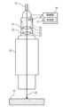
図2に示すように、レーザ加工ヘッド20は、コリメータレンズ21と、フォーカスレンズ22と、検出部25とを有する。 <Configuration of laser processing head>
As shown in FIG. 2 , the
コリメータレンズ21は、伝送ファイバ15の出射端から出射されたレーザ光LBを平行化する。The
フォーカスレンズ22は、コリメータレンズ21で平行化されたレーザ光LBを集光する。フォーカスレンズ22で集光されたレーザ光LBは、ワークWに出射される。The
レーザ光LBは、コリメータレンズ21及びフォーカスレンズ22を透過する際に、その一部が拡散される。When the laser light LB passes through the
検出部25は、コリメータレンズ21及びフォーカスレンズ22で拡散された拡散光DLを検出する。検出部25は、第1レーザ光LB1を受光する第1受光感度が、第2レーザ光LB2を受光する第2受光感度よりも低くなっている。検出部25の検出値は、制御部30に送られる。The
コリメータレンズ21及びフォーカスレンズ22には、ARコート23が設けられている。ARコート23は、第1レーザ光LB1を反射する第1反射率aが、第2レーザ光LB2を反射する第2反射率bよりも高くなっている(図3参照)。The
このように、ARコート23において、第1反射率aを第2反射率bよりも高くする、つまり、第2反射率bを第1反射率aよりも低くすることで、第1反射率a及び第2反射率bを両方とも低くする場合に比べて、コストを抑えることができる。In this way, by making the first reflectance a higher than the second reflectance b in the
ここで、第1反射率aが第2反射率bよりも高いことから、検出部25への拡散光DLの入射量は、第1波長の拡散光DLが第2波長の拡散光DLよりも多くなる。Here, since the first reflectance a is higher than the second reflectance b, the amount of diffused light DL incident on the
そこで、検出部25の第1受光感度を第2受光感度よりも低くすることで、第1波長及び第2波長を含むレーザ光LBのトータルパワーの変動を精度良く検出できるようにしている。Therefore, by making the first light receiving sensitivity of the
具体的に、ARコート23の第1反射率がaのときに、検出部25の第1受光感度を1/aとしている。また、ARコート23の第2反射率がbのときに、検出部25の第2受光感度を1/bとしている(図4参照)。Specifically, when the first reflectance of the
このように、ARコート23の反射率が高くなるほど、検出部25の受光感度が低くなるように設定することで、レーザ光LBのトータルパワーの変動を精度良く検出することができる。In this way, by setting the light receiving sensitivity of the
また、第1レーザ光LB1が青色レーザ光であり、第2レーザ光LB2が赤外レーザ光であるから、第2レーザ光LB2の出力が第1レーザ光LB1の出力よりも高くなっている。In addition, since the first laser light LB1 is blue laser light and the second laser light LB2 is infrared laser light, the output of the second laser light LB2 is higher than the output of the first laser light LB1.
ここで、ARコート23では、第1レーザ光LB1の第1反射率aが第2レーザ光LB2の第2反射率bよりも高い。これにより、低出力な第1レーザ光LB1が、高出力な第2レーザ光LB2よりも検出部25に多く入射されることとなり、検出部25の負荷を小さくすることができる。Here, in the
制御部30は、検出部25の検出値に基づいて、レーザ発振器10の出力を制御する。具体的に、制御部30は、判定部31を有する。判定部31は、レーザ加工ヘッド20の出力の変動を判定する。The
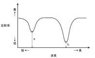
図5に示すように、レーザ発振器10において、光学系の劣化や光軸ずれ等の不具合が生じた場合、レーザ光LBの出力が変動することとなる。そこで、判定部31において、検出部25で検出された拡散光DLのエネルギーが、所定の閾値よりも小さいかを判定する。As shown in Figure 5, when a malfunction such as deterioration of the optical system or misalignment of the optical axis occurs in the
判定部31において、拡散光DLのエネルギーが閾値よりも小さくなった場合に、レーザ発振器10に異常が生じていると判定する。In the
そして、制御部30は、判定部31の判定結果に基づいて、レーザ発振器10の出力を上げることで、レーザ光LBの出力を補正する。Then, the
報知部35は、判定部31の判定結果に基づいて、レーザ発振器10の異常を示す所定の報知動作を行う(図1参照)。例えば、検出部25の検出値が所定の閾値よりも小さい場合に、レーザ光LBの出力が低下したと判断して、警報ブザーを鳴らす、警報ランプを点灯させる、警報メッセージを表示する等の報知動作を行うようにしている。The
これにより、作業者は、所定の報知動作に基づいて、レーザ加工装置1のメンテナンス時期を判断することができる。This allows the operator to determine when maintenance is required for the
《その他の実施形態》
前記実施形態については、以下のような構成としてもよい。 Other Embodiments
The above embodiment may be configured as follows.
本実施形態では、検出部25において、コリメータレンズ21及びフォーカスレンズ22の両方から拡散される拡散光DLを検出するようにしたが、この形態に限定するものではない。例えば、検出部25において、コリメータレンズ21又はフォーカスレンズ22の一方から拡散される拡散光DLを検出するようにしてもよい。In this embodiment, the
以上説明したように、本開示は、コストを抑えつつ、互いに異なる波長を含むレーザ光の出力の変動を精度良く検出することができるという実用性の高い効果が得られることから、きわめて有用で産業上の利用可能性は高い。As described above, the present disclosure is extremely useful and has high industrial applicability, as it provides the highly practical effect of being able to accurately detect fluctuations in the output of laser light containing different wavelengths while keeping costs down.
1 レーザ加工装置
10 レーザ発振器
15 伝送ファイバ
20 レーザ加工ヘッド
21 コリメータレンズ
22 フォーカスレンズ
23 ARコート
25 検出部
30 制御部
35 報知部
DL 拡散光
LB レーザ光
LB1 第1レーザ光
LB2 第2レーザ光 REFERENCE SIGNS
Claims (5)
Translated fromJapanese前記レーザ光は、第1波長の第1レーザ光と、第2波長の第2レーザ光とを含んでおり、
前記レーザ光を伝送する伝送ファイバと、
前記伝送ファイバで伝送された前記レーザ光を平行化するコリメータレンズと、
前記コリメータレンズで平行化された前記レーザ光を集光するフォーカスレンズと、
前記コリメータレンズ及び前記フォーカスレンズの少なくとも一方から拡散される拡散光を検出する検出部とを備え、
前記コリメータレンズ及び前記フォーカスレンズの少なくとも一方には、ARコートが設けられ、
前記ARコートは、前記第1レーザ光を反射する第1反射率が、前記第2レーザ光を反射する第2反射率よりも高く、
前記検出部は、前記第1レーザ光を受光する第1受光感度が、前記第2レーザ光を受光する第2受光感度よりも低い、レーザ加工ヘッド。 A laser processing head that emits laser light,
the laser light includes a first laser light having a first wavelength and a second laser light having a second wavelength;
a transmission fiber for transmitting the laser light;
a collimator lens for collimating the laser light transmitted through the transmission fiber;
a focus lens that collects the laser light collimated by the collimator lens;
a detection unit that detects diffused light diffused from at least one of the collimator lens and the focus lens,
At least one of the collimator lens and the focus lens is provided with an AR coating;
the AR coating has a first reflectance at which the first laser beam is reflected that is higher than a second reflectance at which the second laser beam is reflected;
The detection unit is a laser processing head, and a first light receiving sensitivity for receiving the first laser light is lower than a second light receiving sensitivity for receiving the second laser light.
前記第1反射率がaのとき、前記第1受光感度が1/aであり、
前記第2反射率がbのとき、前記第2受光感度が1/bである、レーザ加工ヘッド。 In claim 1,
when the first reflectance is a, the first light receiving sensitivity is 1/a,
A laser processing head, wherein when the second reflectance is b, the second light receiving sensitivity is 1/b.
前記第2レーザ光の出力は、前記第1レーザ光の出力よりも高い、レーザ加工ヘッド。 In claim 1 or 2,
A laser processing head, wherein the output of the second laser light is higher than the output of the first laser light.
前記伝送ファイバの入射端に接続され、第1波長及び第2波長を含むレーザ光を発振するレーザ発振器と、
前記検出部の検出値に基づいて、前記レーザ発振器の出力を制御する制御部とを備えた、レーザ加工装置。 A laser processing head according to any one of claims 1 to 3;
a laser oscillator connected to an input end of the transmission fiber and configured to emit laser light having a first wavelength and a second wavelength;
a control unit that controls an output of the laser oscillator based on a detection value of the detection unit.
前記検出部の検出値に基づいて、所定の報知動作を行う報知部を備えた、レーザ加工装置。 In claim 4,
A laser processing device comprising an alarm unit that performs a predetermined alarm operation based on a detection value of the detection unit.
Applications Claiming Priority (3)
| Application Number | Priority Date | Filing Date | Title |
|---|---|---|---|
| JP2020078183 | 2020-04-27 | ||
| JP2020078183 | 2020-04-27 | ||
| PCT/JP2021/014947WO2021220762A1 (en) | 2020-04-27 | 2021-04-08 | Laser processing head and laser processing device |
Publications (2)
| Publication Number | Publication Date |
|---|---|
| JPWO2021220762A1 JPWO2021220762A1 (en) | 2021-11-04 |
| JP7620793B2true JP7620793B2 (en) | 2025-01-24 |
Family
ID=78331529
Family Applications (1)
| Application Number | Title | Priority Date | Filing Date |
|---|---|---|---|
| JP2022517595AActiveJP7620793B2 (en) | 2020-04-27 | 2021-04-08 | Laser processing head and laser processing device |
Country Status (3)
| Country | Link |
|---|---|
| JP (1) | JP7620793B2 (en) |
| DE (1) | DE112021001183T5 (en) |
| WO (1) | WO2021220762A1 (en) |
Citations (4)
| Publication number | Priority date | Publication date | Assignee | Title |
|---|---|---|---|---|
| JP2001196665A (en) | 2000-01-13 | 2001-07-19 | Hamamatsu Kagaku Gijutsu Kenkyu Shinkokai | Two wavelength laser machining optical apparatus and laser machining method |
| JP2005101504A (en) | 2003-08-22 | 2005-04-14 | Topcon Corp | Laser equipment |
| JP2005161361A (en) | 2003-12-02 | 2005-06-23 | Fujitsu Ltd | Laser processing machine management method and laser processing machine |
| WO2016060095A1 (en) | 2014-10-14 | 2016-04-21 | 株式会社アマダホールディングス | Direct diode laser processing device and output monitoring method for same |
Family Cites Families (2)
| Publication number | Priority date | Publication date | Assignee | Title |
|---|---|---|---|---|
| JPS6257789A (en)* | 1985-08-20 | 1987-03-13 | Nippon Steel Corp | Method for monitoring laser beam machining device |
| JP2014079802A (en) | 2012-10-18 | 2014-05-08 | Sumitomo Electric Ind Ltd | Laser processing method and laser beam irradiation device |
- 2021
- 2021-04-08DEDE112021001183.9Tpatent/DE112021001183T5/enactivePending
- 2021-04-08JPJP2022517595Apatent/JP7620793B2/enactiveActive
- 2021-04-08WOPCT/JP2021/014947patent/WO2021220762A1/ennot_activeCeased
Patent Citations (4)
| Publication number | Priority date | Publication date | Assignee | Title |
|---|---|---|---|---|
| JP2001196665A (en) | 2000-01-13 | 2001-07-19 | Hamamatsu Kagaku Gijutsu Kenkyu Shinkokai | Two wavelength laser machining optical apparatus and laser machining method |
| JP2005101504A (en) | 2003-08-22 | 2005-04-14 | Topcon Corp | Laser equipment |
| JP2005161361A (en) | 2003-12-02 | 2005-06-23 | Fujitsu Ltd | Laser processing machine management method and laser processing machine |
| WO2016060095A1 (en) | 2014-10-14 | 2016-04-21 | 株式会社アマダホールディングス | Direct diode laser processing device and output monitoring method for same |
Also Published As
| Publication number | Publication date |
|---|---|
| DE112021001183T5 (en) | 2022-12-29 |
| WO2021220762A1 (en) | 2021-11-04 |
| JPWO2021220762A1 (en) | 2021-11-04 |
| US20230023205A1 (en) | 2023-01-26 |
Similar Documents
| Publication | Publication Date | Title |
|---|---|---|
| JP6373714B2 (en) | Direct diode laser processing apparatus and output monitoring method thereof | |
| US7651264B2 (en) | Laser processing device, laser processing temperature measuring device, laser processing method and laser processing temperature measuring method | |
| US11060905B2 (en) | Laser device | |
| US11607746B2 (en) | Laser device and laser processing device using same | |
| WO2019049914A1 (en) | Laser device | |
| JP7620793B2 (en) | Laser processing head and laser processing device | |
| JP7620794B2 (en) | Laser processing head and laser processing device | |
| TWI802917B (en) | Laser optical path system and lidar | |
| US12440920B2 (en) | Laser processing head and laser processing device | |
| US11806812B2 (en) | Laser machining device | |
| EP4074454B1 (en) | Laser device and method for controlling laser device | |
| JP2010239079A (en) | Semiconductor laser module | |
| KR101138454B1 (en) | Laser system for output measurement and prevention of exit-hole damage and method of check normality. | |
| JP7291501B2 (en) | Laser processing equipment | |
| JP7105157B2 (en) | LASER OSCILLATOR AND LASER OSCILLATOR TEMPERATURE MONITORING METHOD | |
| JP4664718B2 (en) | Laser processing apparatus and output control method thereof | |
| US11179800B2 (en) | Laser processing device | |
| JP2023135369A (en) | Laser processing device | |
| JP2023082229A (en) | Laser processing head and laser processing device | |
| JP2017144466A (en) | Power monitoring device and laser processing machine | |
| JP2024157431A (en) | Laser Processing Equipment | |
| JP2023065071A (en) | Laser processing device | |
| JP4574340B2 (en) | Wavelength conversion laser device | |
| JP2025007313A (en) | Laser oscillator and laser processing device equipped with same | |
| JP2021176639A (en) | Laser processing head and laser processing equipment |
Legal Events
| Date | Code | Title | Description |
|---|---|---|---|
| RD01 | Notification of change of attorney | Free format text:JAPANESE INTERMEDIATE CODE: A7421 Effective date:20221024 | |
| A621 | Written request for application examination | Free format text:JAPANESE INTERMEDIATE CODE: A621 Effective date:20231012 | |
| RD01 | Notification of change of attorney | Free format text:JAPANESE INTERMEDIATE CODE: A7421 Effective date:20240918 | |
| TRDD | Decision of grant or rejection written | ||
| A01 | Written decision to grant a patent or to grant a registration (utility model) | Free format text:JAPANESE INTERMEDIATE CODE: A01 Effective date:20241126 | |
| A61 | First payment of annual fees (during grant procedure) | Free format text:JAPANESE INTERMEDIATE CODE: A61 Effective date:20241209 | |
| R150 | Certificate of patent or registration of utility model | Ref document number:7620793 Country of ref document:JP Free format text:JAPANESE INTERMEDIATE CODE: R150 |