JP7619397B1 - Remote operator terminal, remote operation support method, and remote operation system - Google Patents
Remote operator terminal, remote operation support method, and remote operation systemDownload PDFInfo
- Publication number
- JP7619397B1 JP7619397B1JP2023120698AJP2023120698AJP7619397B1JP 7619397 B1JP7619397 B1JP 7619397B1JP 2023120698 AJP2023120698 AJP 2023120698AJP 2023120698 AJP2023120698 AJP 2023120698AJP 7619397 B1JP7619397 B1JP 7619397B1
- Authority
- JP
- Japan
- Prior art keywords
- vehicle
- remote operator
- remote
- display device
- moving object
- Prior art date
- Legal status (The legal status is an assumption and is not a legal conclusion. Google has not performed a legal analysis and makes no representation as to the accuracy of the status listed.)
- Active
Links
Images


Landscapes
- Closed-Circuit Television Systems (AREA)
- User Interface Of Digital Computer (AREA)
Abstract
Translated fromJapaneseDescription
Translated fromJapanese本開示は、遠隔オペレータにより行われる移動体の遠隔操作に関する。This disclosure relates to remote operation of a moving object performed by a remote operator.
特許文献1は、作業機械を遠隔制御する際の画像表示方法を開示している。作業機械には前方カメラと後方カメラが取り付けられる。前方カメラと後方カメラによって撮影される画像が、遠隔操作側のディスプレイに表示される。このとき、前方カメラと後方カメラのいずれか一方により撮影される画像が、他方により撮影される画像よりも大きく表示される。Patent Document 1 discloses an image display method for remotely controlling a work machine. A front camera and a rear camera are attached to the work machine. Images captured by the front camera and the rear camera are displayed on the display of the remote control device. At this time, the image captured by either the front camera or the rear camera is displayed larger than the image captured by the other camera.
遠隔オペレータにより行われる移動体の遠隔操作について考える。移動体を右折あるいは左折させる際、遠隔オペレータは、移動体が他の物体を巻き込まないように移動体の周囲の状況を確認する。Consider remote control of a moving object by a remote operator. When turning right or left, the remote operator checks the situation around the moving object to ensure that the moving object does not hit other objects.
本開示の1つの目的は、遠隔オペレータが移動体を右折あるいは左折させる際の安全確認をより容易に行うことができる技術を提供することにある。One objective of the present disclosure is to provide technology that enables a remote operator to more easily check for safety when turning a mobile vehicle right or left.
第1の観点は、移動体の遠隔操作を行う遠隔オペレータのための遠隔オペレータ端末に関する。
遠隔オペレータ端末は、移動体に搭載された後側方カメラによって撮影される後側方画像を表示する表示装置を備える。
表示装置は、更に、移動体の後方における移動体の軌跡を後側方画像に重ねて表示する。 The first aspect relates to a remote operator terminal for a remote operator who remotely operates a mobile object.
The remote operator terminal includes a display device that displays rear-side images captured by the rear-side cameras mounted on the vehicle.
The display device further displays the trajectory of the moving object behind the moving object by superimposing it on the rear side image.
第2の観点は、移動体の遠隔操作を行う遠隔オペレータに対する情報を表示装置に表示する遠隔操作支援方法に関する。
遠隔操作支援方法は、
移動体に搭載された後側方カメラによって撮影される後側方画像を表示装置に表示することと、
移動体の後方における移動体の軌跡を後側方画像に重ねて表示することと
を含む
。 The second aspect relates to a remote operation support method for displaying information for a remote operator who remotely operates a mobile object on a display device.
The remote operation support method is as follows:
Displaying a rear-side image captured by a rear-side camera mounted on the moving object on a display device;
and displaying a trajectory of the moving object behind the moving object in a manner superimposed on the rear side image.
第3の観点は、遠隔操作システムに関する。
遠隔操作システムは、
移動体の遠隔操作を制御する1又は複数のプロセッサと、
移動体の遠隔操作を行う遠隔オペレータに対する情報を表示する表示装置と
を備える。
1又は複数のプロセッサは、移動体に搭載された後側方カメラによって撮影される後側方画像を取得する。
1又は複数のプロセッサは、移動体の後方における移動体の軌跡の情報を取得する。
1又は複数のプロセッサは、移動体の軌跡を後側方画像に重ねて表示装置に表示する。 The third aspect relates to a remote control system.
The remote control system is
One or more processors for controlling remote operation of the mobile object;
and a display device that displays information for a remote operator who remotely controls the mobile object.
The one or more processors acquire rear-side images taken by a rear-side camera mounted on the vehicle.
The one or more processors obtain information on the trajectory of the moving object behind the moving object.
The one or more processors display the trajectory of the moving object on the display device by superimposing the trajectory on the rear-side image.
本開示によれば、移動体の遠隔操作に用いられる表示装置は、移動体に搭載された後側方カメラによって撮影される後側方画像を表示する。更に、表示装置は、移動体の後方における移動体の軌跡を後側方画像に重ねて表示する。遠隔オペレータは、移動体の軌跡が重ねられた後側方画像を見ることによって、移動体の左折あるいは右折時の安全確認をより容易に行うことができる。これにより、遠隔オペレータは、より安全に移動体の遠隔操作を行うことが可能となる。According to the present disclosure, a display device used for remotely controlling a moving body displays a rear-side image captured by a rear-side camera mounted on the moving body. Furthermore, the display device displays the trajectory of the moving body behind the moving body superimposed on the rear-side image. By looking at the rear-side image with the trajectory of the moving body superimposed, the remote operator can more easily check for safety when the moving body turns left or right. This allows the remote operator to remotely control the moving body more safely.
添付図面を参照して、本開示の実施の形態を説明する。An embodiment of the present disclosure will be described with reference to the attached drawings.
1.遠隔操作システムの概要
移動体の遠隔操作(遠隔運転)について考える。特に、地上を走行する移動体の遠隔操作について考える。遠隔操作の対象である移動体としては、車両、ロボット、等が例示される。車両は、自動運転車両であってもよいし、ドライバが運転する車両であってもよい。ロボットとしては、物流ロボット、作業ロボット、等が例示される。一例として、以下の説明においては、移動体が車両である場合について考える。一般化する場合には、以下の説明における「車両」を「移動体」で読み替えるものとする。 1. Overview of the Remote Control System Consider the remote control (remote driving) of a moving object. In particular, consider the remote control of a moving object traveling on the ground. Examples of moving objects that are the subject of remote control include vehicles and robots. The vehicle may be an autonomous vehicle or a vehicle driven by a driver. Examples of robots include logistics robots and work robots. As an example, in the following explanation, consider the case where the moving object is a vehicle. When generalizing, "vehicle" in the following explanation should be read as "moving object".
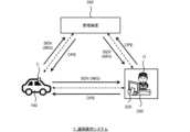
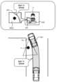
図1は、本実施の形態に係る遠隔操作システム1の構成例を示す概略図である。遠隔操作システム1は、車両100、遠隔オペレータ端末200、及び管理装置300を含んでいる。車両100は、遠隔操作の対象である。遠隔オペレータ端末200は、遠隔オペレータOが車両100を遠隔操作する際に使用する端末装置である。遠隔オペレータ端末200を遠隔操作HMI(Human Machine Interface)と言うこともできる。管理装置300は、遠隔操作システム1の管理を行う。典型的には、管理装置300は、クラウド上の管理サーバである。管理サーバは、分散処理を行う複数のサーバにより構成されていてもよい。FIG. 1 is a schematic diagram showing an example of the configuration of a remote operation system 1 according to the present embodiment. The remote operation system 1 includes a
車両100、遠隔オペレータ端末200、及び管理装置300は、通信ネットワークを介して互いに通信可能である。車両100と遠隔オペレータ端末200は、管理装置300を介して互いに通信可能である。また、車両100と遠隔オペレータ端末200は、管理装置300を介さずに直接通信を行ってもよい。The
車両100には、カメラCを含む各種センサが搭載されている。カメラCは、車両100の周囲を撮影し、車両100の周囲の状況を示す画像(映像)IMGを取得する。センサ検出情報SENは、各種センサにより得られる情報を含む。センサ検出情報SENは、少なくとも、カメラCにより撮影される画像IMGを含む。センサ検出情報SENは、車両100の位置及び状態(例:速度、操舵角、等)を含んでいてもよい。車両100は、センサ検出情報SENを遠隔オペレータ端末200に送信する。The
遠隔オペレータ端末200は、車両100から送信されたセンサ検出情報SENを受け取る。遠隔オペレータ端末200は、センサ検出情報SENを遠隔オペレータOに提示する。具体的には、遠隔オペレータ端末200は、表示装置220を備えており、画像IMG等の情報を表示装置220に表示する。遠隔オペレータOは、表示された情報をみて、車両100の周囲の状況を認識し、車両100の遠隔操作を行う。つまり、遠隔オペレータOに対する情報を表示装置220に表示することによって、遠隔オペレータOによる車両100の遠隔操作が支援される。The
遠隔操作情報OPEは、遠隔オペレータOによる遠隔操作に関する情報である。例えば、遠隔操作情報OPEは、遠隔オペレータOによる操作量を含む。遠隔オペレータ端末200は、遠隔操作情報OPEを車両100に送信する。車両100は、遠隔オペレータ端末200から送信された遠隔操作情報OPEを受け取る。車両100は、受け取った遠隔操作情報OPEに従って車両走行制御を行う。このようにして、車両100の遠隔操作が実現される。The remote operation information OPE is information related to remote operation by the remote operator O. For example, the remote operation information OPE includes the amount of operation by the remote operator O. The
2.表示装置及び表示される画像の例
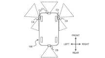
図2は、車両100に搭載されるカメラCの例を示す概念図である。図2に示される例では、車両100は、前方カメラC1、左前方カメラC2、右前方カメラC3、左後方カメラC4、右後方カメラC5、及び後方カメラC6を備えている。前方カメラC1は、車両100の前方を撮影するように設置されている。左前方カメラC2は、車両100の左前方を撮影するように設置されている。右前方カメラC3は、車両100の右前方を撮影するように設置されている。左後方カメラC4は、車両100の左後方を撮影するように設置されている。右後方カメラC5は、車両100の右後方を撮影するように設置されている。後方カメラC6は、車両100の後方を撮影するように設置されている。 2. Example of display device and displayed image FIG. 2 is a conceptual diagram showing an example of a camera C mounted on a
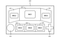
図3は、遠隔オペレータ端末200の表示装置220の一例を説明するための概念図である。表示装置220は、車両100に搭載されたカメラCによって撮影される画像IMGを表示する。図3に示される例では、表示装置220は、表示領域(表示部)221~226を含んでいる。表示領域221には、前方カメラC1によって撮影され、車両100の前方の状況を示す前方画像IMG1が表示される。表示領域222には、左前方カメラC2によって撮影され、車両100の左前方の状況を示す左前方画像IMG2が表示される。表示領域223には、右前方カメラC3によって撮影され、車両100の右前方の状況を示す右前方画像IMG3が表示される。表示領域224には、左後方カメラC4によって撮影され、車両100の左後方の状況を示す左後方画像IMG4が表示される。表示領域225には、右後方カメラC5によって撮影され、車両100の右後方の状況を示す右後方画像IMG5が表示される。表示領域226には、後方カメラC6によって撮影され、車両100の後方の状況を示す後方画像IMG6が表示される。Figure 3 is a conceptual diagram for explaining an example of the
尚、遠隔オペレータ端末200はタブレット型であってもよい。遠隔オペレータ端末200の表示装置220は、タッチパネルであってもよい。タッチパネルには、遠隔オペレータOが車両100を遠隔操作するための操作部231、232が表示されてもよい。遠隔オペレータOは、タッチパネル上の操作部231、232をタッチすることによって、車両100を遠隔操作することができる。The
図2で例示された左後方カメラC4と右後方カメラC5は、車両100の後側方を撮影するための「後側方カメラ」であると言える。また、図3で例示された左後方画像IMG4と右後方画像IMG5は、車両100の後側方の状況を示す「後側方画像」であると言える。表示装置220は、後側方カメラによって撮影される後側方画像を表示する。遠隔オペレータOは、表示される後側方画像を見ることによって、車両100の後側方の状況を確認することができる。これは、車両100に搭乗しているドライバがサイドミラーを見て後側方の状況を確認することに相当する。The left rear camera C4 and right rear camera C5 illustrated in FIG. 2 can be considered to be "rear side cameras" for capturing images of the rear sides of the
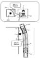
表示装置220に表示される後側方画像は、例えば、遠隔オペレータOが車両100を左折あるいは右折させる際の安全確認に有用である。一例として、図4は、遠隔オペレータOが車両100を左折させるシーンを示している。遠隔オペレータOは、左後方カメラC4によって撮影される左後方画像IMG4を見ることによって、車両100が他の物体X(例:歩行者、自転車)を巻き込まないように注意することができる。すなわち、遠隔オペレータOは、左後方画像IMG4を見て安全確認を行いながら、車両100を慎重に左折させることができる。このように、遠隔オペレータOによる車両100の遠隔操作が支援される。The rear side image displayed on the
3.軌跡表示処理
遠隔オペレータOが車両100を右折あるいは左折させる際の安全確認をより容易に行うことができることが望まれる。 3. Trajectory Display Processing It is desirable for the remote operator O to be able to more easily check for safety when turning the
一例として、後側方画像(IMG4,IMG5)が表示される表示領域(224、225)を大きくすることが考えられる。但し、表示装置220のサイズに制限がある場合もあり、特定の表示領域を自由に拡大することができるとは限らない。また、表示装置220のサイズに制限がある場合、特定の表示領域が大きくなると、その分、他の表示領域が小さくなってしまう。他の表示領域が小さくなると、遠隔オペレータOが遠隔操作を円滑に行いづらくなるおそれがある。As an example, it is possible to enlarge the display area (224, 225) in which the rear side images (IMG4, IMG5) are displayed. However, there may be limitations on the size of the
そこで、本実施の形態では、別のアプローチが採用される。より詳細には、遠隔オペレータ端末200の表示装置220は、必要に応じて、車両100の後方における車両100の軌跡TRを後側方画像(IMG4,IMG5)に重ねて表示する。車両100の軌跡TRを後側方画像に重ねて表示することを、以下、「軌跡表示処理」と呼ぶ。軌跡表示処理は、例えば、拡張現実(AR)技術により実現される。Therefore, in this embodiment, a different approach is adopted. More specifically, the
図5は、軌跡表示処理の一例を説明するための概念図である。図5に示される例において、車両100の軌跡TRは、過去の一定期間内に車両100が通過した領域である。過去の一定期間内に車両100が通過した領域を、以下、「通過領域」と呼ぶ。Figure 5 is a conceptual diagram for explaining an example of the trajectory display process. In the example shown in Figure 5, the trajectory TR of the
車両位置PVは、車両100の代表点の位置である。例えば、車両位置PVは、車両100の中心点の位置である。現在の車両位置PVから見た過去の一定期間における車両位置PVの履歴は、過去の一定期間における車両100の操舵角と速度に基づいて算出可能である。車幅Wは、車両100の横幅であり、既知情報である。図5に示されるように、通過領域は、車両位置PVの履歴に沿って延在する車幅Wの領域である。車両位置PVが車両100の中心点の位置である場合、通過領域の中心線は車両位置PVの履歴に一致する。車両位置PVの履歴と車両100の車幅Wを組み合わせることによって、過去の一定期間における通過領域を推定することが可能である。The vehicle position PV is the position of a representative point of the
他の例として、車両位置PVの履歴から、車両100の各車輪の位置の履歴が算出されてもよい。車両位置PVから見た各車輪の設置位置は既知情報であり、その既知情報に基づいて各車輪の位置の履歴を算出することができる。この場合、車両100の全車輪の位置の履歴によって囲まれる領域が、通過領域として用いられる。As another example, the position history of each wheel of the
更に他の例として、絶対座標系における車両位置PVの履歴が用いられてもよい。絶対座標系における車両位置PVは、車両100に搭載されたGNSS(Global Navigation Satellite System)センサによって計測される。あるいは、絶対座標系における車両位置PVは、周知の自己位置推定(Localization)によって算出される。現在の車両位置PVを用いることによって、絶対座標系における車両位置PVの履歴を、現在の車両位置PVから見た車両位置PVの履歴に変換することができる。As yet another example, a history of the vehicle position PV in the absolute coordinate system may be used. The vehicle position PV in the absolute coordinate system is measured by a Global Navigation Satellite System (GNSS) sensor mounted on the
遠隔オペレータ端末200の表示装置220は、車両100の通過領域(軌跡TR)を後側方画像に重ねて表示する。車両100に搭載された後側方カメラの設置位置、設置向き、及び画角は既知情報である。その既知情報と現在の車両位置PVから見た通過領域を組み合わせることによって、通過領域を後側方画像に重ねて表示することができる。通過領域を後側方画像に重ねることは、例えば拡張現実(AR)技術に基づいて行われる。図5に示される例では、左後方カメラC4によって撮影される左後方画像IMG4に通過領域が重ねられる。そして、通過領域が重ねられた左後方画像IMG4が表示領域224に表示される。The
遠隔オペレータOは、通過領域が重ねられた後側方画像を見て、安全確認を行う。他の物体X(例:歩行者、自転車)が通過領域の外側に映っている場合、車両100が物体Xを巻き込まないように特に注意が必要である。遠隔オペレータOは、車両100を停止させてもよい。車両100の近傍に存在する他の物体Xが検知された場合、遠隔オペレータ端末200は、表示及び音声の少なくとも一方を通して遠隔オペレータOに注意喚起を行ってもよい。The remote operator O checks for safety by looking at the rear-side image with the passing area superimposed. If another object X (e.g., a pedestrian or a bicycle) is shown outside the passing area, special care must be taken to ensure that the
図6は、軌跡表示処理の他の例を説明するための概念図である。図6に示される例において、車両100の軌跡TRは、上述の通過領域の境界線である。通過領域の境界線の位置は、通過領域の位置から算出可能である。その他は、図5で説明された例と同様である。Figure 6 is a conceptual diagram for explaining another example of the trajectory display process. In the example shown in Figure 6, the trajectory TR of the
図7は、軌跡表示処理の更に他の例を説明するための概念図である。図7に示される例では、車両100は、トラクタ101と、トラクタ101によって牽引されるトレーラ102を含んでいる。後側方カメラは、トラクタ101に搭載されている。図7に示される例では、車両100の軌跡TRは、トレーラ102の軌跡TRである。トラクタ101とトレーラ102との接続態様、トラクタ101とトレーラ102の各々の車輪の位置、等は既知情報である。その既知情報と車両位置PVに基づいて、トレーラ102の軌跡TRを推定することができる。そして、トレーラ102の軌跡TRが後側方画像に重ねられる。Figure 7 is a conceptual diagram for explaining yet another example of the trajectory display process. In the example shown in Figure 7, the
図8は、軌跡表示処理のON/OFFを説明するための概念図である。軌跡表示処理は、所定の軌跡表示条件が成立する場合にのみ選択的に実行されてもよい。例えば、軌跡表示処理は、車両100の左折あるいは右折と連動して行われる。そのために、車両100の操舵角、遠隔オペレータOによる操舵量、あるいは、車両100のウィンカの作動状態がモニタされる。例えば、車両100の操舵角が閾値を超えている場合に軌跡表示処理がONし、操舵角が閾値以下である場合に軌跡表示処理がOFFする。他の例として、遠隔オペレータOによる操舵量が閾値を超えている場合に軌跡表示処理がONし、操舵量が閾値以下である場合に軌跡表示処理がOFFする。更に他の例として、車両100のウィンカが作動中の場合に軌跡表示処理がONし、ウィンカが作動していない場合は軌跡表示処理がOFFしてもよい。Figure 8 is a conceptual diagram for explaining ON/OFF of the trajectory display process. The trajectory display process may be selectively executed only when a predetermined trajectory display condition is satisfied. For example, the trajectory display process is performed in conjunction with a left or right turn of the
<効果>
以上に説明されたように、本実施の形態によれば、車両100の遠隔操作に用いられる表示装置220は、車両100に搭載された後側方カメラによって撮影される後側方画像を表示する。更に、表示装置220は、車両100の後方における車両100の軌跡TRを後側方画像に重ねて表示する。遠隔オペレータOは、車両100の軌跡TRが重ねられた後側方画像を見ることによって、車両100の左折あるいは右折時の安全確認をより容易に行うことができる。例えば、他の物体X(例:歩行者、自転車)が車両100の軌跡TRの外側に映っている場合、遠隔オペレータOは、車両100が物体Xを巻き込まないように特に注意を払うことができる。これにより、遠隔オペレータOは、より安全に車両100の遠隔操作を行うことが可能となる。 <Effects>
As described above, according to the present embodiment, the
また、本実施の形態によれば、後側方画像(IMG4,IMG5)が表示される表示領域(224、225)を必要以上に大きくする必要がない。よって、表示装置220のサイズに制限がある場合であっても、他の表示領域をいたずらに狭める必要がない。このことは、円滑な遠隔操作の観点から好適である。Furthermore, according to this embodiment, it is not necessary to make the display areas (224, 225) in which the rear side images (IMG4, IMG5) are displayed larger than necessary. Therefore, even if there is a limit to the size of the
軌跡表示処理は、所定の軌跡表示条件が成立する場合にのみ選択的に実行されてもよい。この場合、軌跡表示処理が常時実行されるわけではないため、遠隔操作システム1における処理負荷が軽減される。The trajectory display process may be selectively executed only when a predetermined trajectory display condition is met. In this case, the trajectory display process is not executed all the time, so the processing load on the remote control system 1 is reduced.
4.機能構成例
図9は、本実施の形態に係る軌跡表示処理に関連する機能構成例を示すブロック図である。遠隔操作システム1は、機能ブロックとして、情報取得部10、判定部20、画像処理部30、及び表示制御部40を含んでいる。図10は、本実施の形態に係る軌跡表示処理に関連する処理を示すフローチャートである。以下、図9及び図10を参照して、本実施の形態に係る軌跡表示装置に関連する処理について説明する。 4. Functional Configuration Example Fig. 9 is a block diagram showing a functional configuration example related to the path display processing according to this embodiment. The remote control system 1 includes, as functional blocks, an
4-1.情報取得処理(ステップS10)
ステップS10において、情報取得部10は、各種情報を取得する。より詳細には、情報取得部10は、車両100に搭載されたカメラCによって撮影される画像IMGを取得する。また、情報取得部10は、車両100に関する車両情報VCLを取得する。 4-1. Information acquisition process (step S10)
In step S10, the
例えば、車両情報VCLは、車両100に搭載された各カメラCの設置位置、設置向き、及び画角の情報を含んでいる。この情報は、既知情報である。For example, the vehicle information VCL includes information on the installation position, installation direction, and angle of view of each camera C mounted on the
車両情報VCLは、車両100の諸元情報を含んでいてもよい。諸元情報は、車幅W、各車輪の設置位置、ホイールベース、トレッド、等を含む。車両100がトラクタ101とトレーラ102を含む場合(図7参照)、車両100の諸元情報は、トラクタ101とトレーラ102との接続態様、トラクタ101とトレーラ102の各々の車輪の位置、等を含んでいてもよい。The vehicle information VCL may include specification information of the
車両情報VCLは、車両100の操舵角と速度の情報を含んでいてもよい。車両100の操舵角と速度は、センサ検出情報SENから得られる。The vehicle information VCL may include information on the steering angle and speed of the
車両情報VCLは、車両100のウィンカの作動状態を示す情報を含んでいてもよい。ウィンカの作動状態は、センサ検出情報SENから得られる。The vehicle information VCL may include information indicating the operation status of the turn signal of the
車両情報VCLは、絶対座標系における車両位置PVの情報を含んでいてもよい。絶対座標系における車両位置PVは、例えば、車両100に搭載されたGNSSセンサによって計測される。The vehicle information VCL may include information on the vehicle position PV in an absolute coordinate system. The vehicle position PV in the absolute coordinate system is measured, for example, by a GNSS sensor mounted on the
情報取得部10は、更に、車両100の後方における車両100の軌跡TRの情報を取得する。図5で示された例では、車両100の軌跡TRは、過去の一定期間内に車両100が通過した通過領域である。図6で示された例では、車両100の軌跡TRは、通過領域の境界線である。図7で示された例では、車両100の軌跡TRは、トレーラ102の軌跡TRである。いずれの場合であっても、情報取得部10は、上述の車両情報VCLに基づいて、車両100の軌跡TRを算出(推定)することができる。The
情報取得部10は、更に、遠隔操作情報OPEを取得してもよい。遠隔操作情報OPEは、遠隔オペレータOによる操作量(例:操舵量)を含む。遠隔操作情報OPEは、遠隔オペレータOによる方向指示器の操作状態を含んでいてもよい。The
4-2.判定処理(ステップS20)
ステップS20において、判定部20は、所定の軌跡表示条件が成立するか否かを判定する。 4-2. Judgment process (step S20)
In step S20, the
例えば、所定の軌跡表示条件は、「車両100の操舵角あるいは遠隔オペレータOによる操舵量が閾値を超えていること」である。車両100の操舵角は、上述の車両情報VCLに含まれている。遠隔オペレータOによる操舵量は、遠隔操作情報OPEに含まれている。車両100の操舵角は、遠隔オペレータOによる操舵量から算出されてもよい。判定部20は、車両情報VCLあるいは遠隔操作情報OPEに基づいて、車両100の操舵角あるいは遠隔オペレータOによる操舵量が閾値を超えているか否かを判定することができる。For example, the specified trajectory display condition is that "the steering angle of the
他の例として、所定の軌跡表示条件は、「車両100のウィンカが作動中であること」である。車両100のウィンカの作動状態は、上述の車両情報VCLから得られる。あるいは、遠隔オペレータOによる方向指示器の操作状態が、車両100のウィンカの作動状態とみなされてもよい。判定部20は、車両情報VCLあるいは遠隔操作情報OPEに基づいて、車両100のウィンカが作動中であるか否かを判定することができる。As another example, the specified trajectory display condition is "the blinker of the
更に他の例として、所定の軌跡表示条件は、遠隔オペレータOが軌跡表示機能をONしていることを含んでいてもよい。As yet another example, the specified trajectory display condition may include the remote operator O having the trajectory display function turned ON.
所定の軌跡表示条件が成立する場合(ステップS20;Yes)、処理は、ステップS30に進む。一方、所定の軌跡表示条件が成立しない場合(ステップS20;No)、処理は、ステップS35に進む。If the specified path display condition is met (step S20; Yes), the process proceeds to step S30. On the other hand, if the specified path display condition is not met (step S20; No), the process proceeds to step S35.
4-3.画像処理(ステップS30、S35)
ステップS30において、画像処理部30は、後側方カメラによって撮影された後側方画像に車両100の軌跡TRを重ね合わせる。車両100に搭載された後側方カメラの設置位置、設置向き、及び画角は、車両情報VCLから得られる。よって、画像処理部30は、画像IMG、軌跡TR、及び車両情報VCLに基づいて、後側方画像に車両100の軌跡TRを重ね合わせることができる。画像処理部30は、車両100の軌跡TRが重ねられた後側方画像を含む画像IMGを表示制御部40に出力する。 4-3. Image processing (steps S30, S35)
In step S30, the
一方、ステップS35において、画像処理部30は、後側方画像に車両100の軌跡TRを重ね合わせない。画像処理部30は、画像IMGをそのまま表示制御部40に出力する。On the other hand, in step S35, the
4-4.表示制御処理(ステップS40)
ステップS40において、表示制御部40は、遠隔オペレータ端末200の表示装置220に画像IMGを表示する。車両100の軌跡TRが後側方画像に重ねられている場合、表示制御部40は、車両100の軌跡TRが重ねられた後側方画像を表示装置220に表示する。一方、車両100の軌跡TRが後側方画像に重ねられていない場合、表示制御部40は、後側方画像をそのまま表示装置220に表示する。 4-4. Display control process (step S40)
In step S40, the
尚、図1で示されたように、車両100、遠隔オペレータ端末200、及び管理装置300は、通信ネットワークを介して互いに通信可能であり、必要な情報をやり取り可能である。よって、情報取得部10は、車両100、遠隔オペレータ端末200、及び管理装置300のいずれに含まれていてもよい。同様に、判定部20は、車両100、遠隔オペレータ端末200、及び管理装置300のいずれに含まれていてもよい。同様に、画像処理部30は、車両100、遠隔オペレータ端末200、及び管理装置300のいずれに含まれていてもよい。表示制御部40は、遠隔オペレータ端末200に含まれている。As shown in FIG. 1, the
5.車両の構成例
5-1.構成例
図11は、車両100の構成例を示すブロック図である。車両100は、通信装置110、センサ群120、走行装置130、及び制御装置150を備えている。 11 is a block diagram showing an example of the configuration of a
通信装置110は、車両100の外部と通信を行う。例えば、通信装置110は、遠隔オペレータ端末200や管理装置300と通信を行う。The
センサ群120は、認識センサ、車両状態センサ、位置センサ、等を含んでいる。認識センサは、車両100の周辺の状況を認識(検出)する。認識センサとしては、カメラC、LIDAR(Laser Imaging Detection and Ranging)、レーダ、等が例示される。車両状態センサは、車両100の状態を検出する。車両状態センサは、速度センサ、加速度センサ、ヨーレートセンサ、舵角センサ、等を含んでいる。位置センサは、車両100の位置及び方位を検出する。例えば、位置センサは、GNSSセンサを含んでいる。The
走行装置130は、操舵装置、駆動装置、及び制動装置を含んでいる。操舵装置は、車輪を転舵する。例えば、操舵装置は、パワーステアリング(EPS: Electric Power Steering)装置を含んでいる。駆動装置は、駆動力を発生させる動力源である。駆動装置としては、エンジン、電動機、インホイールモータ、等が例示される。制動装置は、制動力を発生させる。The traveling
制御装置150は、車両100を制御するコンピュータである。制御装置150は、1又は複数のプロセッサ160(以下、単にプロセッサ160と呼ぶ)と1又は複数の記憶装置170(以下、単に記憶装置170と呼ぶ)を含んでいる。プロセッサ160は、各種処理を実行する。プロセッサ160として、CPU(Central Processing Unit)、GPU(Graphics Processing Unit)、ASIC(Application Specific Integrated Circuit)、FPGA(Field-Programmable Gate Array)、等が例示される。記憶装置170は、各種情報を格納する。記憶装置170としては、揮発性メモリ、不揮発性メモリ、HDD(Hard Disk Drive)、SSD(Solid State Drive)、等が例示される。制御装置150は、1又は複数のECU(Electronic Control Unit)を含んでいてもよい。The
車両制御プログラムPROG1は、プロセッサ160によって実行されるコンピュータプログラムである。車両制御プログラムPROG1を実行するプロセッサ160と記憶装置170との協働により、制御装置150の機能が実現されてもよい。車両制御プログラムPROG1は、記憶装置170に格納される。あるいは、車両制御プログラムPROG1は、コンピュータ読み取り可能な記録媒体に記録されてもよい。The vehicle control program PROG1 is a computer program executed by the
5-2.センサ検出情報
制御装置150は、センサ群120を用いてセンサ検出情報SENを取得する。センサ検出情報SENは、記憶装置170に格納される。センサ検出情報SENは、画像IMG、物体情報、等を含んでいる。画像IMGは、カメラCによって撮影される。 The
物体情報は、車両100の周囲の物体に関する情報である。車両100の周囲の物体としては、歩行者、自転車、二輪車、他車両(先行車両、並走車両、後続車両、等)、白線、道路構造物(例:縁石、ガードレール)、ポール、信号、標識、等が例示される。制御装置150は、認識センサを用いることによって車両100の周囲の物体を認識することができる。例えば、画像IMGを解析することによって、物体を識別し、その物体の相対位置を算出することができる。また、LIDARによって得られた点群情報に基づいて、物体を識別し、その物体の相対位置と相対速度を取得することもできる。物体情報は、車両100に対する物体の相対位置を含む。物体情報は、更に、物体の相対速度を含んでいてもよい。The object information is information about objects around the
5-3.車両走行制御
制御装置150は、車両100の走行を制御する車両走行制御を実行する。車両走行制御は、操舵制御、駆動制御、及び制動制御を含む。制御装置150は、走行装置130(操舵装置、駆動装置、及び制動装置)を制御することによって車両走行制御を実行する。 5-3. Vehicle Driving Control The
制御装置150は、センサ検出情報SENに基づいて自動運転制御を行ってもよい。より詳細には、制御装置150は、センサ検出情報SENに基づいて、車両100の走行プランを生成する。更に、制御装置150は、センサ検出情報SENに基づいて、車両100が走行プランに従って走行するために必要な目標トラジェクトリを生成する。目標トラジェクトリは、目標位置及び目標速度を含んでいる。そして、制御装置150は、車両100が目標トラジェクトリに追従するように車両走行制御を行う。The
5-4.遠隔操作に関連する処理
車両100の遠隔操作が行われる場合、制御装置150は、通信装置110を介して遠隔オペレータ端末200と通信を行う。 5-4. Processing Related to Remote Operation When the
制御装置150は、センサ検出情報SENの少なくとも一部を遠隔オペレータ端末200に送信する。典型的には、制御装置150は、画像IMGを遠隔オペレータ端末200に送信する。制御装置150は、物体情報を遠隔オペレータ端末200に送信してもよい。制御装置150は、車両情報VCLを遠隔オペレータ端末200に送信してもよい。The
また、制御装置150は、遠隔操作情報OPEを遠隔オペレータ端末200から受信する。遠隔操作情報OPEは、遠隔オペレータOによる遠隔操作に関する情報である。例えば、遠隔操作情報OPEは、遠隔オペレータOによる操作量を含む。制御装置150は、受信した遠隔操作情報OPEに従って車両走行制御を行う。The
更に、制御装置150は、図9で示された情報取得部10、判定部20、及び画像処理部30のうち少なくとも1つの機能を備えていてもよい。Furthermore, the
6.遠隔オペレータ端末の構成例
図12は、遠隔オペレータ端末200の構成例を示すブロック図である。遠隔オペレータ端末200は、通信装置210、表示装置220、入力装置230、及び制御装置250を含んでいる。 12 is a block diagram showing an example of the configuration of the
通信装置210は、車両100及び管理装置300と通信を行う。The
表示装置220は、遠隔操作を行う遠隔オペレータOに対する各種情報を表示する。言い換えれば、表示装置220は、各種情報を表示することにより、各種情報を遠隔オペレータOに提示する。表示装置220は、タッチパネルであってもよい(図3参照)。The
入力装置230は、遠隔オペレータOが車両100を遠隔操作する際に操作する部材である。例えば、入力装置230は、遠隔操作部材を含んでいる。遠隔操作部材は、ハンドル、アクセルペダル、ブレーキペダル、方向指示器、等を含んでいる。The
表示装置220と入力装置230は、一体的に構成されたユーザインタフェースであってもよい。例えば、表示装置220と入力装置230は、一体的に構成されたタッチパネルであってもよい。タッチパネルは、表示領域(表示部)221~226や操作部231、232を含んでいてもよい(図3参照)。The
制御装置250は、遠隔オペレータ端末200を制御する。制御装置250は、1又は複数のプロセッサ260(以下、単にプロセッサ260と呼ぶ)と1又は複数の記憶装置270(以下、単に記憶装置270と呼ぶ)を含んでいる。プロセッサ260は、各種処理を実行する。プロセッサ260として、CPU、GPU、ASIC、FPGA、等が例示される。記憶装置270は、プ各種情報を格納する。記憶装置270としては、揮発性メモリ、不揮発性メモリ、HDD、SSD、等が例示される。The
遠隔操作制御プログラムPROG2は、プロセッサ260によって実行されるコンピュータプログラムである。遠隔操作制御プログラムPROG2を実行するプロセッサ260と記憶装置270の協働により、制御装置250の機能が実現されてもよい。遠隔操作制御プログラムPROG2は、記憶装置270に格納される。あるいは、遠隔操作制御プログラムPROG2は、コンピュータ読み取り可能な記録媒体に記録されてもよい。遠隔操作制御プログラムPROG2は、ネットワーク経由で提供されてもよい。The remote operation control program PROG2 is a computer program executed by the
制御装置250は、通信装置210を介して、車両100と通信を行う。制御装置250は、車両100から送信されるセンサ検出情報SENを受信する。制御装置250は、受信したセンサ検出情報SENのうち必要な情報を遠隔オペレータOに提示する。例えば、制御装置250は、画像IMGを表示装置220に表示することによって、画像IMGを遠隔オペレータOに提示する。つまり、制御装置250は、図9で示された表示制御部40の機能を有する。遠隔オペレータOは、提示された情報に基づいて、車両100の状態や周囲の状況を認識することができる。The
遠隔オペレータOは、入力装置230を操作する。入力装置230の操作量は、入力装置230に設置されたセンサにより検出される。制御装置250は、遠隔オペレータOによる入力装置230の操作量を反映した遠隔操作情報OPEを生成する。そして、制御装置250は、その遠隔操作情報OPEを通信装置210を介して車両100に送信する。The remote operator O operates the
更に、制御装置250は、図9で示された情報取得部10、判定部20、及び画像処理部30のうち少なくとも1つの機能を備えていてもよい。Furthermore, the
1 遠隔操作システム
10 情報取得部
20 判定部
30 画像処理部
40 表示制御部
100 車両
101 トラクタ
102 トレーラ
200 遠隔オペレータ端末
220 表示装置
250 制御装置
260 プロセッサ
270 記憶装置
300 管理装置
IMG 画像
OPE 遠隔操作情報
SEN センサ検出情報
TR 軌跡
VCL 車両情報 REFERENCE SIGNS LIST 1
Claims (8)
Translated fromJapanese前記移動体と通信を行い、前記移動体に搭載されたカメラによって撮影される画像を前記移動体から取得し、また、前記遠隔オペレータによる前記遠隔操作に関する遠隔操作情報を前記移動体に送信するように構成された制御装置と、
複数の表示領域を有する表示装置と
を備え、
前記画像は、前記移動体に搭載された後側方カメラによって撮影される後側方画像と、前記移動体に搭載された後方カメラによって撮影される後方画像とを含み、
前記表示装置は、前記後側方画像と前記後方画像とをそれぞれ異なる表示領域に表示し、
前記表示装置は、更に、前記移動体の左折あるいは右折と連動して、過去の一定期間内に前記移動体が通過した通過領域を前記後側方画像に重ねて表示し、
前記通過領域は、前記移動体の車輪以外の部分が通過した領域も含む
遠隔オペレータ端末。 A remote operator terminal for a remote operator who remotely operates a moving object, comprising:
a control device configured to communicate with the mobile body, acquire from the mobile body an image captured by a camera mounted on the mobile body, and transmit to the mobile body remote operation information regarding the remote operation by the remote operator;
A display device having a plurality of display areas;
Equipped with
The images include a rear-side image captured by a rear-side camera mounted on the moving body and a rear image captured by a rear camera mounted on the moving body,
The display device displays therear side image and therear image in different display areas,
The display device further displays, in conjunction with a left turn or a right turn of the moving object, a passing area through which the moving object has passed within a certain period of time in the past, superimposed on the rear-side image;
The passing area includes an area through which parts of the moving object other than the wheels have passed.
前記移動体の操舵角あるいは前記遠隔オペレータによる操舵量が閾値を超えている場合、前記表示装置は、前記通過領域を前記後側方画像に重ねて表示し、
前記移動体の前記操舵角あるいは前記遠隔オペレータによる前記操舵量が前記閾値以下である場合、前記表示装置は、前記通過領域を重ね合わせることなく前記後側方画像を表示する
遠隔オペレータ端末。 2. A remote operator terminal according to claim 1, comprising:
When the steering angle of the moving object or the steering amount by the remote operator exceeds a threshold, the display device displays the passing area by superimposing it on the rear side image,
When the steering angle of the moving object or the steering amount by the remote operator is equal to or smaller than the threshold value, the display device displays the rear side image without superimposing the passing area.
前記移動体のウィンカが作動中である場合、前記表示装置は、前記通過領域を前記後側方画像に重ねて表示し、
前記移動体の前記ウィンカが作動していない場合、前記表示装置は、前記通過領域を重ね合わせることなく前記後側方画像を表示する
遠隔オペレータ端末。 2. A remote operator terminal according to claim 1, comprising:
When a blinker of the moving object is in operation, the display device displays the passing area by superimposing it on the rear side image,
When the turn signal of the vehicle is not activated, the display device displays the rear side image without superimposing the passing area.
前記通過領域は、前記移動体の現在位置から見た前記過去の一定期間における前記移動体の位置履歴に基づいて推定される
遠隔オペレータ端末。 A remote operator terminal according to any one of claims 1 to 3, comprising:
The passing area is estimated based on a position history of the mobile object during the past certain period of time as viewed from the current position of the mobile object.
前記通過領域は、前記過去の一定期間における前記移動体の前記位置履歴に沿って延在する前記移動体の横幅と同じ幅の領域である
遠隔オペレータ端末。 5. A remote operator terminal as claimed in claim 4, comprising:
The passing area is an area having the same width as the width of the moving object extending along the position history of the moving object during the past certain period of time.
前記通過領域は、前記過去の一定期間における前記移動体の前記位置履歴に対応する前記移動体の全車輪の位置履歴によって囲まれる領域である
遠隔オペレータ端末。 5. A remote operator terminal as claimed in claim 4, comprising:
The passing area is an area bounded by the position history of all wheels of the moving body corresponding to the position history of the moving body during the past fixed period of time.
前記遠隔オペレータ端末は、前記移動体と通信を行い、前記移動体に搭載されたカメラによって撮影される画像を前記移動体から取得し、また、前記遠隔オペレータによる前記遠隔操作に関する遠隔操作情報を前記移動体に送信するように構成され、
前記画像は、前記移動体に搭載された後側方カメラによって撮影される後側方画像と、前記移動体に搭載された後方カメラによって撮影される後方画像とを含み、
前記表示装置は、複数の表示領域を有し、
前記遠隔操作支援方法は、
前記後側方画像と前記後方画像とをそれぞれ異なる表示領域に表示することと、
前記移動体の左折あるいは右折と連動して、過去の一定期間内に前記移動体が通過した通過領域を前記後側方画像に重ねて表示することと
を含み、
前記通過領域は、前記移動体の車輪以外の部分が通過した領域も含む
遠隔操作支援方法。 A remote operation support method for displaying information for a remote operator who remotely operates a mobile object on a display deviceof a remote operator terminal , comprising:
the remote operator terminal is configured to communicate with the mobile body, acquire from the mobile body an image captured by a camera mounted on the mobile body, and transmit to the mobile body remote operation information regarding the remote operation by the remote operator;
The images include a rear-side image captured by a rear-side camera mounted on the moving body and a rear image captured by a rear camera mounted on the moving body,
The display device has a plurality of display areas,
The remote operation assistance method includes:
Displaying therear side image and therear image in different display areas;
and displaying, in conjunction with a left or right turn of the moving object, a passing area through which the moving object has passed within a certain period of time in the past, superimposed on the rear-side image,
The said passing area includes an area through which parts of the moving object other than the wheels have passed.
前記移動体の前記遠隔操作を行う遠隔オペレータに対する情報を表示する遠隔オペレータ端末の表示装置と
を備え、
前記遠隔オペレータ端末は、前記移動体と通信を行い、前記移動体に搭載されたカメラによって撮影される画像を前記移動体から取得し、また、前記遠隔オペレータによる前記遠隔操作に関する遠隔操作情報を前記移動体に送信するように構成され、
前記画像は、前記移動体に搭載された後側方カメラによって撮影される後側方画像と、前記移動体に搭載された後方カメラによって撮影される後方画像とを含み、
前記表示装置は、複数の表示領域を有し、
前記1又は複数のプロセッサは、更に、
前記後側方画像と前記後方画像とをそれぞれ異なる表示領域に表示し、
前記移動体の左折あるいは右折と連動して、過去の一定期間内に前記移動体が通過した通過領域を前記後側方画像に重ねて前記表示装置に表示する
ように構成され、
前記通過領域は、前記移動体の車輪以外の部分が通過した領域も含む
遠隔操作システム。 One or more processors for controlling remote operation of the mobile object;
a display deviceof a remote operator terminal that displays information for a remote operator who remotely operates the moving object,
the remote operator terminal is configured to communicate with the mobile body, acquire from the mobile body an image captured by a camera mounted on the mobile body, and transmit to the mobile body remote operation information regarding the remote operation by the remote operator;
The images include a rear-side image captured by a rear-side camera mounted on the moving body and a rear image captured by a rear camera mounted on the moving body,
The display device has a plurality of display areas,
The one or more processorsfurther include:
Therear side image and therear image are displayed in different display areas,
In conjunction with a left or right turn of the moving object, a passing area through which the moving object has passed within a certain period of time in the past is displayed on the display device by being superimposed on the rear side image,
A remote control system, wherein the passing area includes an area through which parts of the moving object other than the wheels have passed.
Priority Applications (1)
| Application Number | Priority Date | Filing Date | Title |
|---|---|---|---|
| JP2023120698AJP7619397B1 (en) | 2023-07-25 | 2023-07-25 | Remote operator terminal, remote operation support method, and remote operation system |
Applications Claiming Priority (1)
| Application Number | Priority Date | Filing Date | Title |
|---|---|---|---|
| JP2023120698AJP7619397B1 (en) | 2023-07-25 | 2023-07-25 | Remote operator terminal, remote operation support method, and remote operation system |
Publications (2)
| Publication Number | Publication Date |
|---|---|
| JP7619397B1true JP7619397B1 (en) | 2025-01-22 |
| JP2025017575A JP2025017575A (en) | 2025-02-06 |
Family
ID=94279056
Family Applications (1)
| Application Number | Title | Priority Date | Filing Date |
|---|---|---|---|
| JP2023120698AActiveJP7619397B1 (en) | 2023-07-25 | 2023-07-25 | Remote operator terminal, remote operation support method, and remote operation system |
Country Status (1)
| Country | Link |
|---|---|
| JP (1) | JP7619397B1 (en) |
Citations (12)
| Publication number | Priority date | Publication date | Assignee | Title |
|---|---|---|---|---|
| JP2004114879A (en) | 2002-09-27 | 2004-04-15 | Clarion Co Ltd | Parking assisting device, and image display device |
| US20060287825A1 (en) | 1999-06-25 | 2006-12-21 | Fujitsu Ten Limited | Vehicle drive assist system |
| JP2008290669A (en) | 2007-05-28 | 2008-12-04 | Toyota Motor Corp | Start support device, display device, route calculation device |
| US20110307176A1 (en) | 2009-03-30 | 2011-12-15 | Delphi Technologies, Inc. | Vehicle handling assistant apparatus |
| JP2014040190A (en) | 2012-08-23 | 2014-03-06 | Isuzu Motors Ltd | Rear wheel track display device |
| JP2014067299A (en) | 2012-09-26 | 2014-04-17 | Aisin Seiki Co Ltd | Vehicle driving assist device |
| US20140292805A1 (en) | 2013-03-29 | 2014-10-02 | Fujitsu Ten Limited | Image processing apparatus |
| JP2016101872A (en) | 2014-11-28 | 2016-06-02 | アイシン精機株式会社 | Vehicle periphery monitoring device |
| JP2017033542A (en) | 2015-07-29 | 2017-02-09 | 株式会社デンソー | Information display |
| JP2019156298A (en) | 2018-03-15 | 2019-09-19 | 株式会社デンソーテン | Vehicle remote control device and vehicle remote control method |
| JP2021111854A (en) | 2020-01-08 | 2021-08-02 | トヨタ自動車株式会社 | Electronic mirror system for vehicles |
| JP2021111814A (en) | 2020-01-06 | 2021-08-02 | フォルシアクラリオン・エレクトロニクス株式会社 | Tow support device |
- 2023
- 2023-07-25JPJP2023120698Apatent/JP7619397B1/enactiveActive
Patent Citations (12)
| Publication number | Priority date | Publication date | Assignee | Title |
|---|---|---|---|---|
| US20060287825A1 (en) | 1999-06-25 | 2006-12-21 | Fujitsu Ten Limited | Vehicle drive assist system |
| JP2004114879A (en) | 2002-09-27 | 2004-04-15 | Clarion Co Ltd | Parking assisting device, and image display device |
| JP2008290669A (en) | 2007-05-28 | 2008-12-04 | Toyota Motor Corp | Start support device, display device, route calculation device |
| US20110307176A1 (en) | 2009-03-30 | 2011-12-15 | Delphi Technologies, Inc. | Vehicle handling assistant apparatus |
| JP2014040190A (en) | 2012-08-23 | 2014-03-06 | Isuzu Motors Ltd | Rear wheel track display device |
| JP2014067299A (en) | 2012-09-26 | 2014-04-17 | Aisin Seiki Co Ltd | Vehicle driving assist device |
| US20140292805A1 (en) | 2013-03-29 | 2014-10-02 | Fujitsu Ten Limited | Image processing apparatus |
| JP2016101872A (en) | 2014-11-28 | 2016-06-02 | アイシン精機株式会社 | Vehicle periphery monitoring device |
| JP2017033542A (en) | 2015-07-29 | 2017-02-09 | 株式会社デンソー | Information display |
| JP2019156298A (en) | 2018-03-15 | 2019-09-19 | 株式会社デンソーテン | Vehicle remote control device and vehicle remote control method |
| JP2021111814A (en) | 2020-01-06 | 2021-08-02 | フォルシアクラリオン・エレクトロニクス株式会社 | Tow support device |
| JP2021111854A (en) | 2020-01-08 | 2021-08-02 | トヨタ自動車株式会社 | Electronic mirror system for vehicles |
Also Published As
| Publication number | Publication date |
|---|---|
| JP2025017575A (en) | 2025-02-06 |
Similar Documents
| Publication | Publication Date | Title |
|---|---|---|
| US10392009B2 (en) | Automatic parking system and automatic parking method | |
| EP3016835B1 (en) | Vehicle control system | |
| CN112477758B (en) | Peripheral monitoring device | |
| US11691619B2 (en) | Automatic parking system and automatic parking method | |
| US9429946B2 (en) | Driving control system and dynamic decision control method thereof | |
| US11648932B2 (en) | Periphery monitoring device | |
| US10878253B2 (en) | Periphery monitoring device | |
| US10179608B2 (en) | Parking assist device | |
| US10315569B2 (en) | Surroundings monitoring apparatus and program thereof | |
| US20160075377A1 (en) | Parking assist system, parking assist method and parking assist control program | |
| US11511805B2 (en) | Vehicle guidance device, method, and computer program product | |
| JP2016097896A (en) | Image display control device | |
| JP2012076483A (en) | Parking support device | |
| US20220073104A1 (en) | Traffic accident management device and traffic accident management method | |
| CN113589820A (en) | Auxiliary processing method, device and system for remote driving | |
| CN110877575B (en) | Peripheral monitoring device | |
| CN112124090A (en) | Park assist system | |
| US12043310B2 (en) | Driver assistance system and control method for the same | |
| JP2020083048A (en) | Image display device | |
| JP7619397B1 (en) | Remote operator terminal, remote operation support method, and remote operation system | |
| US20210403020A1 (en) | Vehicular control system with detection and prevention of unintended motion | |
| CN115675467A (en) | Operation assist system for vehicle | |
| US20250304092A1 (en) | Driving assistance device, vehicle, control method for driving assistance device, and storage medium | |
| US20240336140A1 (en) | Driving assistance apparatus, driving assistance method, and non-transitory recording medium | |
| US20240282120A1 (en) | Information processing apparatus, information processing method, and storage medium |
Legal Events
| Date | Code | Title | Description |
|---|---|---|---|
| A621 | Written request for application examination | Free format text:JAPANESE INTERMEDIATE CODE: A621 Effective date:20230731 | |
| A131 | Notification of reasons for refusal | Free format text:JAPANESE INTERMEDIATE CODE: A131 Effective date:20240611 | |
| A521 | Request for written amendment filed | Free format text:JAPANESE INTERMEDIATE CODE: A523 Effective date:20240730 | |
| A131 | Notification of reasons for refusal | Free format text:JAPANESE INTERMEDIATE CODE: A131 Effective date:20240924 | |
| A521 | Request for written amendment filed | Free format text:JAPANESE INTERMEDIATE CODE: A523 Effective date:20241017 | |
| A131 | Notification of reasons for refusal | Free format text:JAPANESE INTERMEDIATE CODE: A131 Effective date:20241029 | |
| A521 | Request for written amendment filed | Free format text:JAPANESE INTERMEDIATE CODE: A523 Effective date:20241204 | |
| TRDD | Decision of grant or rejection written | ||
| A01 | Written decision to grant a patent or to grant a registration (utility model) | Free format text:JAPANESE INTERMEDIATE CODE: A01 Effective date:20241210 | |
| A61 | First payment of annual fees (during grant procedure) | Free format text:JAPANESE INTERMEDIATE CODE: A61 Effective date:20241223 | |
| R150 | Certificate of patent or registration of utility model | Ref document number:7619397 Country of ref document:JP Free format text:JAPANESE INTERMEDIATE CODE: R150 |