JP7619206B2 - Control device, program, and power management system - Google Patents
Control device, program, and power management systemDownload PDFInfo
- Publication number
- JP7619206B2 JP7619206B2JP2021132847AJP2021132847AJP7619206B2JP 7619206 B2JP7619206 B2JP 7619206B2JP 2021132847 AJP2021132847 AJP 2021132847AJP 2021132847 AJP2021132847 AJP 2021132847AJP 7619206 B2JP7619206 B2JP 7619206B2
- Authority
- JP
- Japan
- Prior art keywords
- charging
- power
- processor
- demand
- control device
- Prior art date
- Legal status (The legal status is an assumption and is not a legal conclusion. Google has not performed a legal analysis and makes no representation as to the accuracy of the status listed.)
- Active
Links
Images


Classifications
- B—PERFORMING OPERATIONS; TRANSPORTING
- B60—VEHICLES IN GENERAL
- B60L—PROPULSION OF ELECTRICALLY-PROPELLED VEHICLES; SUPPLYING ELECTRIC POWER FOR AUXILIARY EQUIPMENT OF ELECTRICALLY-PROPELLED VEHICLES; ELECTRODYNAMIC BRAKE SYSTEMS FOR VEHICLES IN GENERAL; MAGNETIC SUSPENSION OR LEVITATION FOR VEHICLES; MONITORING OPERATING VARIABLES OF ELECTRICALLY-PROPELLED VEHICLES; ELECTRIC SAFETY DEVICES FOR ELECTRICALLY-PROPELLED VEHICLES
- B60L53/00—Methods of charging batteries, specially adapted for electric vehicles; Charging stations or on-board charging equipment therefor; Exchange of energy storage elements in electric vehicles
- B60L53/60—Monitoring or controlling charging stations
- B60L53/62—Monitoring or controlling charging stations in response to charging parameters, e.g. current, voltage or electrical charge
- B—PERFORMING OPERATIONS; TRANSPORTING
- B60—VEHICLES IN GENERAL
- B60L—PROPULSION OF ELECTRICALLY-PROPELLED VEHICLES; SUPPLYING ELECTRIC POWER FOR AUXILIARY EQUIPMENT OF ELECTRICALLY-PROPELLED VEHICLES; ELECTRODYNAMIC BRAKE SYSTEMS FOR VEHICLES IN GENERAL; MAGNETIC SUSPENSION OR LEVITATION FOR VEHICLES; MONITORING OPERATING VARIABLES OF ELECTRICALLY-PROPELLED VEHICLES; ELECTRIC SAFETY DEVICES FOR ELECTRICALLY-PROPELLED VEHICLES
- B60L53/00—Methods of charging batteries, specially adapted for electric vehicles; Charging stations or on-board charging equipment therefor; Exchange of energy storage elements in electric vehicles
- B60L53/60—Monitoring or controlling charging stations
- B60L53/66—Data transfer between charging stations and vehicles
- B60L53/665—Methods related to measuring, billing or payment
- B—PERFORMING OPERATIONS; TRANSPORTING
- B60—VEHICLES IN GENERAL
- B60L—PROPULSION OF ELECTRICALLY-PROPELLED VEHICLES; SUPPLYING ELECTRIC POWER FOR AUXILIARY EQUIPMENT OF ELECTRICALLY-PROPELLED VEHICLES; ELECTRODYNAMIC BRAKE SYSTEMS FOR VEHICLES IN GENERAL; MAGNETIC SUSPENSION OR LEVITATION FOR VEHICLES; MONITORING OPERATING VARIABLES OF ELECTRICALLY-PROPELLED VEHICLES; ELECTRIC SAFETY DEVICES FOR ELECTRICALLY-PROPELLED VEHICLES
- B60L53/00—Methods of charging batteries, specially adapted for electric vehicles; Charging stations or on-board charging equipment therefor; Exchange of energy storage elements in electric vehicles
- B60L53/60—Monitoring or controlling charging stations
- B60L53/68—Off-site monitoring or control, e.g. remote control
- B—PERFORMING OPERATIONS; TRANSPORTING
- B60—VEHICLES IN GENERAL
- B60L—PROPULSION OF ELECTRICALLY-PROPELLED VEHICLES; SUPPLYING ELECTRIC POWER FOR AUXILIARY EQUIPMENT OF ELECTRICALLY-PROPELLED VEHICLES; ELECTRODYNAMIC BRAKE SYSTEMS FOR VEHICLES IN GENERAL; MAGNETIC SUSPENSION OR LEVITATION FOR VEHICLES; MONITORING OPERATING VARIABLES OF ELECTRICALLY-PROPELLED VEHICLES; ELECTRIC SAFETY DEVICES FOR ELECTRICALLY-PROPELLED VEHICLES
- B60L58/00—Methods or circuit arrangements for monitoring or controlling batteries or fuel cells, specially adapted for electric vehicles
- B60L58/10—Methods or circuit arrangements for monitoring or controlling batteries or fuel cells, specially adapted for electric vehicles for monitoring or controlling batteries
- B60L58/12—Methods or circuit arrangements for monitoring or controlling batteries or fuel cells, specially adapted for electric vehicles for monitoring or controlling batteries responding to state of charge [SoC]
- G—PHYSICS
- G06—COMPUTING OR CALCULATING; COUNTING
- G06Q—INFORMATION AND COMMUNICATION TECHNOLOGY [ICT] SPECIALLY ADAPTED FOR ADMINISTRATIVE, COMMERCIAL, FINANCIAL, MANAGERIAL OR SUPERVISORY PURPOSES; SYSTEMS OR METHODS SPECIALLY ADAPTED FOR ADMINISTRATIVE, COMMERCIAL, FINANCIAL, MANAGERIAL OR SUPERVISORY PURPOSES, NOT OTHERWISE PROVIDED FOR
- G06Q10/00—Administration; Management
- G06Q10/06—Resources, workflows, human or project management; Enterprise or organisation planning; Enterprise or organisation modelling
- G06Q10/063—Operations research, analysis or management
- G06Q10/0631—Resource planning, allocation, distributing or scheduling for enterprises or organisations
- G06Q10/06315—Needs-based resource requirements planning or analysis
- G—PHYSICS
- G06—COMPUTING OR CALCULATING; COUNTING
- G06Q—INFORMATION AND COMMUNICATION TECHNOLOGY [ICT] SPECIALLY ADAPTED FOR ADMINISTRATIVE, COMMERCIAL, FINANCIAL, MANAGERIAL OR SUPERVISORY PURPOSES; SYSTEMS OR METHODS SPECIALLY ADAPTED FOR ADMINISTRATIVE, COMMERCIAL, FINANCIAL, MANAGERIAL OR SUPERVISORY PURPOSES, NOT OTHERWISE PROVIDED FOR
- G06Q30/00—Commerce
- G06Q30/06—Buying, selling or leasing transactions
- G06Q30/0601—Electronic shopping [e-shopping]
- G06Q30/0631—Recommending goods or services
- G—PHYSICS
- G06—COMPUTING OR CALCULATING; COUNTING
- G06Q—INFORMATION AND COMMUNICATION TECHNOLOGY [ICT] SPECIALLY ADAPTED FOR ADMINISTRATIVE, COMMERCIAL, FINANCIAL, MANAGERIAL OR SUPERVISORY PURPOSES; SYSTEMS OR METHODS SPECIALLY ADAPTED FOR ADMINISTRATIVE, COMMERCIAL, FINANCIAL, MANAGERIAL OR SUPERVISORY PURPOSES, NOT OTHERWISE PROVIDED FOR
- G06Q50/00—Information and communication technology [ICT] specially adapted for implementation of business processes of specific business sectors, e.g. utilities or tourism
- G06Q50/06—Energy or water supply
- B—PERFORMING OPERATIONS; TRANSPORTING
- B60—VEHICLES IN GENERAL
- B60L—PROPULSION OF ELECTRICALLY-PROPELLED VEHICLES; SUPPLYING ELECTRIC POWER FOR AUXILIARY EQUIPMENT OF ELECTRICALLY-PROPELLED VEHICLES; ELECTRODYNAMIC BRAKE SYSTEMS FOR VEHICLES IN GENERAL; MAGNETIC SUSPENSION OR LEVITATION FOR VEHICLES; MONITORING OPERATING VARIABLES OF ELECTRICALLY-PROPELLED VEHICLES; ELECTRIC SAFETY DEVICES FOR ELECTRICALLY-PROPELLED VEHICLES
- B60L2240/00—Control parameters of input or output; Target parameters
- B60L2240/60—Navigation input
- B60L2240/66—Ambient conditions
- Y—GENERAL TAGGING OF NEW TECHNOLOGICAL DEVELOPMENTS; GENERAL TAGGING OF CROSS-SECTIONAL TECHNOLOGIES SPANNING OVER SEVERAL SECTIONS OF THE IPC; TECHNICAL SUBJECTS COVERED BY FORMER USPC CROSS-REFERENCE ART COLLECTIONS [XRACs] AND DIGESTS
- Y02—TECHNOLOGIES OR APPLICATIONS FOR MITIGATION OR ADAPTATION AGAINST CLIMATE CHANGE
- Y02T—CLIMATE CHANGE MITIGATION TECHNOLOGIES RELATED TO TRANSPORTATION
- Y02T10/00—Road transport of goods or passengers
- Y02T10/60—Other road transportation technologies with climate change mitigation effect
- Y02T10/70—Energy storage systems for electromobility, e.g. batteries
- Y—GENERAL TAGGING OF NEW TECHNOLOGICAL DEVELOPMENTS; GENERAL TAGGING OF CROSS-SECTIONAL TECHNOLOGIES SPANNING OVER SEVERAL SECTIONS OF THE IPC; TECHNICAL SUBJECTS COVERED BY FORMER USPC CROSS-REFERENCE ART COLLECTIONS [XRACs] AND DIGESTS
- Y02—TECHNOLOGIES OR APPLICATIONS FOR MITIGATION OR ADAPTATION AGAINST CLIMATE CHANGE
- Y02T—CLIMATE CHANGE MITIGATION TECHNOLOGIES RELATED TO TRANSPORTATION
- Y02T10/00—Road transport of goods or passengers
- Y02T10/60—Other road transportation technologies with climate change mitigation effect
- Y02T10/7072—Electromobility specific charging systems or methods for batteries, ultracapacitors, supercapacitors or double-layer capacitors
- Y—GENERAL TAGGING OF NEW TECHNOLOGICAL DEVELOPMENTS; GENERAL TAGGING OF CROSS-SECTIONAL TECHNOLOGIES SPANNING OVER SEVERAL SECTIONS OF THE IPC; TECHNICAL SUBJECTS COVERED BY FORMER USPC CROSS-REFERENCE ART COLLECTIONS [XRACs] AND DIGESTS
- Y02—TECHNOLOGIES OR APPLICATIONS FOR MITIGATION OR ADAPTATION AGAINST CLIMATE CHANGE
- Y02T—CLIMATE CHANGE MITIGATION TECHNOLOGIES RELATED TO TRANSPORTATION
- Y02T90/00—Enabling technologies or technologies with a potential or indirect contribution to GHG emissions mitigation
- Y02T90/10—Technologies relating to charging of electric vehicles
- Y02T90/12—Electric charging stations
Landscapes
- Engineering & Computer Science (AREA)
- Business, Economics & Management (AREA)
- Human Resources & Organizations (AREA)
- Economics (AREA)
- Strategic Management (AREA)
- Mechanical Engineering (AREA)
- General Business, Economics & Management (AREA)
- General Physics & Mathematics (AREA)
- Theoretical Computer Science (AREA)
- Transportation (AREA)
- Physics & Mathematics (AREA)
- Power Engineering (AREA)
- Marketing (AREA)
- Health & Medical Sciences (AREA)
- Accounting & Taxation (AREA)
- Entrepreneurship & Innovation (AREA)
- Development Economics (AREA)
- Tourism & Hospitality (AREA)
- Finance (AREA)
- Sustainable Energy (AREA)
- Primary Health Care (AREA)
- Life Sciences & Earth Sciences (AREA)
- General Health & Medical Sciences (AREA)
- Public Health (AREA)
- Water Supply & Treatment (AREA)
- Educational Administration (AREA)
- Sustainable Development (AREA)
- Game Theory and Decision Science (AREA)
- Operations Research (AREA)
- Quality & Reliability (AREA)
- Charge And Discharge Circuits For Batteries Or The Like (AREA)
- Supply And Distribution Of Alternating Current (AREA)
- Electric Propulsion And Braking For Vehicles (AREA)
- Management, Administration, Business Operations System, And Electronic Commerce (AREA)
Description
Translated fromJapanese本開示は、制御装置、プログラム、及び、電力管理システムに関する。This disclosure relates to a control device, a program, and a power management system.
特許文献1には、電動車両が使用する充電器の割り当てと充電開始時刻と充電必要量とを含む充電計画にしたがって、充電器のオンとオフとを制御する技術が開示されている。
複数の電動車両の充電需要が大きい場合には、充電設備によって電動車両を充電するための電力を管理する電力需給運用計画が破綻するおそれがある。When there is a high demand for charging multiple electric vehicles, the power supply and demand operation plan that manages the power used to charge electric vehicles by charging equipment may collapse.
本開示は、上記課題に鑑みてなされたものであって、その目的は、電力需給運用計画が破綻することを抑制できる制御装置、プログラム、及び、電力管理システムを提供することである。This disclosure has been made in consideration of the above-mentioned problems, and its purpose is to provide a control device, program, and power management system that can prevent the failure of a power supply and demand operation plan.
本開示に係る制御装置は、複数の電動車両のそれぞれのSOC情報及び充電要求信号に基づいて充電総需要を算出し、算出した充電総需要に基づいて、充電設備によって前記電動車両を充電するための電力を管理する電力需給運用計画を作成する演算を行うプロセッサを有する。The control device according to the present disclosure has a processor that performs calculations to calculate the total charging demand based on the SOC information and charging request signals of each of a plurality of electric vehicles, and to create a power supply and demand operation plan that manages the power used to charge the electric vehicles by the charging equipment based on the calculated total charging demand.
本開示に係るプログラムは、複数の電動車両のそれぞれのSOC情報及び充電要求信号に基づいて充電総需要を算出し、算出した充電総需要に基づいて、充電設備によって前記電動車両を充電するための電力を管理する電力需給運用計画を作成する演算をプロセッサに実行させる。The program disclosed herein calculates the total charging demand based on the SOC information and charging request signals of each of a plurality of electric vehicles, and causes a processor to execute calculations to create a power supply and demand operation plan that manages the power used to charge the electric vehicles by the charging equipment based on the calculated total charging demand.
本開示に係る電力管理システムは、SOC情報及び充電要求信号を出力する第1のプロセッサを有する電動車両と、複数の電動車両のそれぞれの前記SOC情報及び前記充電要求信号に基づいて充電総需要を算出し、算出した充電総需要に基づいて、前記充電設備によって前記電動車両を充電するための電力を管理する電力需給運用計画を作成する演算を行う第2のプロセッサを有する制御装置と、を備える。The power management system according to the present disclosure includes an electric vehicle having a first processor that outputs SOC information and a charging request signal, and a control device having a second processor that calculates a total charging demand based on the SOC information and the charging request signal for each of a plurality of electric vehicles, and performs calculations to create a power supply and demand operation plan that manages the power used to charge the electric vehicles by the charging equipment based on the calculated total charging demand.
本開示においては、電力需給運用計画が破綻することを抑制できるという効果を奏する。This disclosure has the effect of preventing the failure of power supply and demand operation plans.
以下に、本開示に係る制御装置、プログラム、及び、電力管理システムの実施形態について説明する。なお、本実施形態により本開示が限定されるものではない。Embodiments of a control device, a program, and a power management system according to the present disclosure are described below. Note that the present disclosure is not limited to these embodiments.
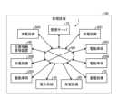
図1は、実施形態に係る電力管理システム1の概略構成を示した図である。電力管理システム1は、管理区域100内に設けられた、管理サーバ10、複数の電動車両20A,20B,20C、複数の充電設備30A,30B,30C、災害情報管理装置40、及び、ネットワークNWなどによって構成されている。Figure 1 is a diagram showing the schematic configuration of a
なお、以下の説明において、電動車両20A,20B,20Cを特に区別しないときには、単に電動車両20と記す。また、充電設備30A,30B,30Cを特に区別しないときには、単に充電設備30と記す。また、図1では、説明の便宜上、3台の電動車両20A,20B,20C、及び、3つの充電設備30A,30B,30Cのみを示すが、管理区域100内に設けられる複数の電動車両20及び複数の充電設備30の数としては、特に限定されるものではない。In the following description, when there is no particular distinction between
電力管理システム1は、例えば、複数の充電設備30A,30B,30Cによって複数の電動車両20A,20B,20Cを充電するための電力を管理する電力需給運用計画に基づいて、複数の充電設備30A,30B,30Cから複数の電動車両20A,20B,20Cへの電力の供給を管理サーバ10によって管理している。The
管理サーバ10、複数の電動車両20A,20B,20C、複数の充電設備30A,30B,30C、及び、災害情報管理装置40は、ネットワークNWを介して互いに通信が可能に構成されている。The
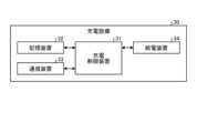
図2は、管理サーバ10の概略構成を示した図である。管理サーバ10は、サーバ制御装置11、記憶装置12、及び、通信装置13などを備えている。Figure 2 shows the schematic configuration of the
サーバ制御装置11は、CPU(Central Processing Unit)、DSP(Digital Signal Processor)、及び、FPGA(Field-Programmable Gate Array)等からなるプロセッサと、RAM(Random Access Memory)、及び、ROM(Read Only Memory)等からなるメモリと、を備えている。サーバ制御装置11は、記憶装置12に格納されたプログラムをメモリの作業領域にロードして実行し、プログラムの実行を通じて各構成部等を制御することにより、所定の目的に合致した機能を実現する。The server control device 11 is equipped with a processor consisting of a CPU (Central Processing Unit), a DSP (Digital Signal Processor), an FPGA (Field-Programmable Gate Array), etc., and memory consisting of a RAM (Random Access Memory), a ROM (Read Only Memory), etc. The server control device 11 loads a program stored in the storage device 12 into the working area of the memory, executes it, and realizes functions that meet a specified purpose by controlling each component, etc. through the execution of the program.
記憶装置12は、EPROM(Erasable Programmable ROM)、ハードディスクドライブ(Hard Disk Drive:HDD)、及び、リムーバブルメディア等の記録媒体から構成される。リムーバブルメディアとしては、例えば、光ディスク(CD(Compact Disc)-RまたはCD-ROM、DVD(Digital Versatile Disc)-RまたはDVD-ROM、BD(Blu-ray(登録商標) Disc)等)、フラッシュメモリ(USB(Universal Serial Bus)メモリ、メモリカード等)等の記録媒体が挙げられる。記憶装置12には、オペレーティングシステム(Operating System:OS)、各種プログラム、各種テーブル、及び、各種データベース等が記憶可能であり、例えば、管理区域100内における複数の充電設備30によって複数の電動車両20を充電するための電力を管理する電力需給運用計画が格納されている。また、記憶装置12には、複数の電動車両20A,20B,20Cのそれぞれを特定するための固有の情報である電動車両IDと、複数の充電設備30A,30B,30Cのそれぞれを特定するための固有の情報である充電設備IDとが記憶されている。The storage device 12 is composed of recording media such as an EPROM (Erasable Programmable ROM), a hard disk drive (HDD), and removable media. Examples of removable media include optical disks (CD (Compact Disc)-R or CD-ROM, DVD (Digital Versatile Disc)-R or DVD-ROM, BD (Blu-ray (registered trademark) Disc), etc.), flash memory (USB (Universal Serial Bus) memory, memory card, etc.), etc. The storage device 12 can store an operating system (OS), various programs, various tables, various databases, and the like, and stores, for example, a power supply and demand operation plan that manages the power for charging the multiple
通信装置13は、例えば、LAN(Local Area Network)インターフェースボード、及び、無線通信のための無線通信回路等から構成される。通信装置13は、公衆通信網であるインターネット等のネットワークNWに接続されている。そして、通信装置13は、ネットワークNWに接続することにより、サーバ制御装置11とネットワークNWとの間で双方向通信を実現する。The communication device 13 is composed of, for example, a LAN (Local Area Network) interface board and a wireless communication circuit for wireless communication. The communication device 13 is connected to a network NW such as the Internet, which is a public communication network. By connecting to the network NW, the communication device 13 realizes two-way communication between the server control device 11 and the network NW.
図3は、電動車両20の概略構成を示した図である。電動車両20は、車両制御装置21、記憶装置22、通信装置23、受電装置24、及び、車載バッテリ25などを備えている。なお、車両制御装置21、記憶装置22、及び、通信装置23の物理的な構成は、例えば、管理サーバ10が備える、サーバ制御装置11、記憶装置12、及び、通信装置13と同様である。Figure 3 is a diagram showing the schematic configuration of the
受電装置24は、充電設備30から受電して車載バッテリ25に電力を供給する。なお、受電装置24の受電方式は、例えば、接触式受電と非接触式受電との少なくとも一方の公知の受電方式を採用することができる。The power receiving device 24 receives power from the
車載バッテリ25は、例えば、ニッケル水素電池やリチウムイオン電池等の二次電池からなり、受電装置24を介して充電設備30から供給される電力によって充電されたり、電動車両20のモータやインバータなどからなる駆動装置に電力を供給したりする。なお、車載バッテリ25としては、電気二重層キャパシタ等のキャパシタも採用可能である。The on-board battery 25 is, for example, a secondary battery such as a nickel-metal hydride battery or a lithium-ion battery, and is charged by power supplied from the
図4は、充電設備30の概略構成を示した図である。充電設備30は、充電制御装置31、記憶装置32、通信装置33、及び、給電装置34などを備えている。なお、充電制御装置31、記憶装置32、及び、通信装置33の物理的な構成は、例えば、管理サーバ10が備える、サーバ制御装置11、記憶装置12、及び、通信装置13と同様である。Figure 4 is a diagram showing the schematic configuration of the
給電装置34は、例えば、電力系統50などの商用電源に接続されており、電動車両20に設けられた受電装置24に給電する。なお、給電装置34の給電方式としては、例えば、接触式給電と非接触式給電との少なくとも一方の公知の給電方式を採用することができる。The power supply device 34 is connected to a commercial power source such as a power grid 50, and supplies power to the power receiving device 24 provided in the
図5は、災害情報管理装置40の概略構成を示した図である。災害情報管理装置40は、情報制御装置41、記憶装置42、及び、通信装置43などを備えている。なお、情報制御装置41、記憶装置42、及び、通信装置43の物理的な構成は、例えば、管理サーバ10が備える、サーバ制御装置11、記憶装置12、及び、通信装置13と同様である。Figure 5 is a diagram showing the schematic configuration of the disaster
災害情報管理装置40は、例えば、管理区域100に関する災害情報を管理サーバ10へ、ネットワークNWを介して出力する装置である。情報制御装置41は、例えば、天気予報を発信している公的機関または民間機関や、国や地方自治体の防災センターなどから、大雨、洪水、台風、及び、地震などの災害に関する情報(以下、災害情報ともいう)を取得して記憶装置42に記憶させる。そして、情報制御装置41は、記憶装置42に記憶させた災害情報を通信装置43によって管理サーバ10に出力する。なお、災害情報には、今後予測される災害の発生予測時刻なども含まれる。The disaster
図1に戻って、電力系統50は、例えば、電気事業者などが提供する発電所及び送配電設備などから構成される電力網である。Returning to FIG. 1, the power system 50 is a power network that is composed of power plants and power transmission and distribution facilities provided by electric power companies, for example.
発電設備60は、例えば、水素供給源から供給される水素を利用して発電を行う燃料電池などによって構成されている。なお、発電設備60としては、石油系燃料やアルコールなどの液体燃料を利用して内燃機関を動作させて回転電機により発電を行う構成であってもよい。発電設備60によって発電した電力は、電力ケーブルなどを介して充電設備30や蓄電設備70などに供給される。The power generation equipment 60 is configured, for example, by a fuel cell that generates electricity using hydrogen supplied from a hydrogen supply source. Note that the power generation equipment 60 may also be configured to generate electricity using a rotating electric machine by operating an internal combustion engine using a liquid fuel such as petroleum fuel or alcohol. The electricity generated by the power generation equipment 60 is supplied to the
蓄電設備70は、例えば、リチウムイオン電池またはニッケル水素電池などの二次電池を備えている。なお、蓄電設備70には、電気二重層キャパシタ等のキャパシタも採用可能である。蓄電設備70は、電力系統50や発電設備60から供給される電力を蓄電したり、充電設備30へ放電したりすることが可能である。The power storage device 70 includes a secondary battery such as a lithium-ion battery or a nickel-metal hydride battery. Note that a capacitor such as an electric double layer capacitor can also be used for the power storage device 70. The power storage device 70 can store power supplied from the power grid 50 or the power generation device 60, and can discharge the power to the
ここで、管理区域100内に点在している複数の充電設備30で電動車両20が車載バッテリ25の充電を行う場合に、複数の充電設備30のそれぞれの使用状況によっては、使用可能な充電設備30を探し回らなければならないおそれがある。また、管理区域100内において、複数の電動車両20による充電総需要が大きい場合には、充電計画が破綻するおそれがある。Here, when an
そのため、実施形態に係る電力管理システム1においては、管理サーバ10のサーバ制御装置11が、複数の電動車両20のそれぞれの車載バッテリ25の残量の情報であるSOC(State Of Charge)情報及び充電要求信号に基づいて、複数の電動車両20のそれぞれの充電電力の期待値を算出し、算出した期待値を管理区域100内の複数の電動車両20について積算することによって、充電総需要を算出する。そして、管理サーバ10は、算出した充電総需要に基づいて電力需給運用計画を作成する。この際、サーバ制御装置11は、前記充電総需要を、発電設備60による発電計画、蓄電設備70による蓄電計画、または、電力系統50からの買電計画へ反映させるように、前記電力需給運用計画を作成する。Therefore, in the
図6は、電動車両20の車両制御装置21が実施する制御ルーチンを示した図である。なお、本制御ルーチンは、例えば、1秒周期で実施される。Figure 6 shows a control routine executed by the vehicle control device 21 of the
まず、車両制御装置21は、ステップS1において、車載バッテリ25のSOCを算出する。次に、車両制御装置21は、ステップS2において、ドライバーからの充電要求が有るか否かを判断する。車両制御装置21は、ドライバーからの充電要求が有ると判断した場合(ステップS2にてYes)、ステップS3において、充電要求信号をONにする。次に、車両制御装置21は、ステップS4において、充電設備30で車載バッテリ25の充電が実施されて、車載バッテリ25の充電が完了したか否かを判断する。車両制御装置21は、車載バッテリ25の充電が完了したと判断した場合(ステップS4にてYes)、ステップS5において、充電要求信号をOFFにする。次に、車両制御装置21は、ステップS6において、通信装置23によってSOC情報の信号と充電要求信号(OFF)とを、ネットワークNWなどを介して管理サーバ10に出力する。そして、車両制御装置21は、本制御ルーチンを終了する。First, in step S1, the vehicle control device 21 calculates the SOC of the vehicle battery 25. Next, in step S2, the vehicle control device 21 determines whether or not there is a charging request from the driver. If the vehicle control device 21 determines that there is a charging request from the driver (Yes in step S2), it turns on the charging request signal in step S3. Next, in step S4, the vehicle control device 21 determines whether or not the charging of the vehicle battery 25 is completed by charging the vehicle battery 25 in the charging
また、ステップS4において、車両制御装置21は、充電設備30で車載バッテリ25の充電を実施しておらず、車載バッテリ25の充電が完了していないと判断した場合(ステップS4にてNo)、ステップS6において、通信装置23によってSOC情報の信号と充電要求信号(ON)とを、ネットワークNWなどを介して管理サーバ10に出力する。そして、車両制御装置21は、本制御ルーチンを終了する。In addition, in step S4, if the vehicle control device 21 determines that the charging
また、ステップS2において、ドライバーからの充電要求がないと判断した場合(ステップS2にてNo)、ステップS5において、充電要求信号をOFFにする。次に、車両制御装置21は、ステップS6において、通信装置23によってSOC情報の信号と充電要求信号(OFF)とを、ネットワークNWなどを介して管理サーバ10に出力する。そして、車両制御装置21は、本制御ルーチンを終了する。If it is determined in step S2 that there is no charge request from the driver (No in step S2), the charge request signal is turned OFF in step S5. Next, in step S6, the vehicle control device 21 outputs a signal of SOC information and a charge request signal (OFF) to the
図7は、管理サーバ10のサーバ制御装置11が実施する電力需給運用計画の算出制御ルーチンを示した図である。Figure 7 shows the calculation control routine for the power supply and demand operation plan implemented by the server control device 11 of the
まず、サーバ制御装置11は、ステップS11において、電動車両20のSOC情報及び充電要求信号を取得する。次に、サーバ制御装置11は、ステップS12において、充電要求信号がONであるか否かを判断する。サーバ制御装置11は、充電要求信号がONであると判断した場合(ステップS12にてYes)、ステップS13において、充電確率を1と算出する。そして、サーバ制御装置11は、ステップS15に移行する。一方、サーバ制御装置11は、充電要求信号がONではないと判断した場合(ステップS12にてNo)、ステップS14において、管理サーバ10の記憶装置12に記憶されている、電動車両20のSOCに応じて充電確率が定まる、SOCと充電確率との関係を表した充電確率マップに基づいて、充電確率を算出する。そして、サーバ制御装置11は、ステップS15に移行する。First, in step S11, the server control device 11 acquires the SOC information and the charge request signal of the
次に、サーバ制御装置11は、ステップS15において、電動車両20が車載バッテリ25の充電にどれだけの充電電力を必要としているのかを示す期待値である充電期待値を算出する。なお、充電期待値は、例えば、充電期待値=(100[%]-SOC[%])/100×充電確率×車載バッテリの充電容量[kWh])の式で算出することができる。次に、サーバ制御装置11は、ステップS16において、管理区域100内における複数の電動車両20のそれぞれの充電期待値を積算して、充電電力の総需要(充電総需要)を算出する。次に、サーバ制御装置11は、ステップS17において、算出した充電電力の総需要(充電総需要)に基づいて、充電電力の総需要(充電総需要)を、CO2の排出量やコストなどを考慮した、発電計画、蓄電計画、または、買電計画へ反映させるように、電力需給運用計画を作成する演算を行う。そして、サーバ制御装置11は、本制御ルーチンを終了する。 Next, in step S15, the server control device 11 calculates a charging expectation value, which is an expectation value indicating how much charging power the
これにより、実施形態に係る電力管理システム1においては、管理区域100内における複数の電動車両20の充電電力の総需要(充電総需要)を事前に算出し、算出した充電電力の総需要(充電総需要)に基づいて電力需給運用計画を算出することによって、複数の電動車両20の充電需要が大きい場合に、電力需給運用計画が破綻することを抑制できる。As a result, in the
また、実施形態に係る電力管理システム1においては、サーバ制御装置11が、複数の充電設備30から推奨する充電設備30を選定する。例えば、サーバ制御装置11は、複数の電動車両20のそれぞれの充電期待値や、複数の電動車両20の充電方式などに基づいて、複数の充電設備30から推奨する充電設備30を選定する。そして、サーバ制御装置11は、推奨する充電設備30に関する情報の信号を、電動車両20に搭載されたカーナビゲーションシステムなどの車載情報端末26と、電動車両20のドライバーが所有するスマートフォンなどの携帯情報端末との少なくとも一方に出力する。In the
図8は、管理サーバ10のサーバ制御装置11が実施する推奨充電設備の選定制御ルーチンを示した図である。Figure 8 shows the recommended charging equipment selection control routine implemented by the server control device 11 of the
まず、サーバ制御装置11は、ステップS21において、電動車両20に関する情報及び当該電動車両20の充電期待値に基づいて、当該電動車両20に対して推奨する充電設備30を選定して割り当てる。次に、サーバ制御装置11は、ステップS22において、電力需給運用計画において、割り当てた充電設備30の使用予定情報を更新する。なお、前記使用予定情報は、例えば、使用開始時刻や使用終了見込み時刻などである。次に、サーバ制御装置11は、ステップS23において、電動車両20のドライバーが所有する携帯情報端末との少なくとも一方に、割り当てた充電設備30に関する情報の信号を出力する。First, in step S21, the server control device 11 selects and assigns a charging
これにより、電動車両20の使用者が、電動車両20の車載バッテリ25を充電するために推奨される充電設備30を事前に知ることができる。これにより、管理区域100内に点在している複数の充電設備30で電動車両20が車載バッテリ25の充電を行う場合に、使用可能な充電設備30を探し回るおそれがあることを抑制することができる。This allows the user of the
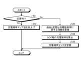
図9は、管理サーバ10のサーバ制御装置11が実施する災害時における充電確率マップの制御ルーチンを示した図である。Figure 9 shows the control routine for the charging probability map during a disaster, which is implemented by the server control device 11 of the
まず、サーバ制御装置11は、ステップS31において、災害情報管理装置40からの災害情報に基づいて、管理区域100内が災害時であるか否かを判断する。サーバ制御装置11は、管理区域100内が災害時であると判断した場合(ステップS31にてYes)、ステップS32において、管理サーバ10の記憶装置12に記憶している充電確率マップ値(SOC毎の充電確率)を嵩上げする(ステップS32)。そして、サーバ制御装置11は、本制御ルーチンを終了する。一方、サーバ制御装置11は、管理区域100内が災害時ではないと判断した場合(ステップS31にてNo)、ステップS33において、過去1週間分の電動車両20に関する情報を、電動車両20から取得して記憶装置12に蓄積する。次に、サーバ制御装置11は、ステップS34において、SOC毎(例えば、SOCが10[%]毎)の充電確率を算出する。次に、サーバ制御装置11は、ステップS35において、充電確率マップを学習する。充電確率マップの学習では、例えば、サーバ制御装置11は、SOCごとに、充電確率マップ値=充電確率×(1/n)+現在の充電確率マップ値×nの式を算出することによって充電確率マップ値を更新する。なお、前記式中のnは、なまし値であり、例えば、n=10とすることができる。そして、サーバ制御装置11は、充電確率マップを学習した後、本制御ルーチンを終了する。First, in step S31, the server control device 11 determines whether or not the
これにより、実施形態に係る電力管理システム1においては、平時よりも電動車両20の充電要求が高まると予測される災害時に、平時よりも充電確率を高く設定して電力需給運用計画を算出することができ、電力需給運用計画が破綻することを抑制することができる。As a result, in the
さらなる効果や変形例は、当業者によって容易に導き出すことができる。本開示のより広範な態様は、以上のように表しかつ記述した特定の詳細および代表的な実施形態に限定されるものではない。したがって、添付のクレームおよびその均等物によって定義される総括的な開示の概念の精神または範囲から逸脱することなく、様々な変更が可能である。Further advantages and modifications can be readily derived by those skilled in the art. The broader aspects of the disclosure are not limited to the specific details and representative embodiments shown and described above. Thus, various modifications may be made without departing from the spirit or scope of the general disclosed concept as defined by the appended claims and equivalents thereof.
1 電力管理システム
10 管理サーバ
11 サーバ制御装置
12,22,32,42 記憶装置
13,23,33,43 通信装置
20,20A,20B,20C 電動車両
21 車両制御装置
24 受電装置
25 車載バッテリ
26 車載情報端末
30,30A,30B,30C 充電設備
31 充電制御装置
34 給電装置
40 災害情報管理装置
41 情報制御装置
50 電力系統
60 発電設備
70 蓄電設備
100 管理区域REFERENCE SIGNS
Claims (14)
Translated fromJapanese制御装置であって、
前記プロセッサは、
前記SOC情報及び前記充電要求信号に基づいて、前記電動車両の充電電力の期待値を算出し、算出した前記期待値を前記複数の電動車両について積算することによって、前記充電総需要を算出し、
前記プロセッサは、
前記期待値を算出する際に用いる、SOCに応じて前記電動車両が充電を実施する可能性を表した確率である充電確率を、災害時に平時よりも高く設定する、
制御装置。 a processor that performs a calculation to calculate a total charging demand based on SOC information and a charging request signal of each of a plurality of electric vehicles, and to create a power supply and demand operation plan that manages power for charging the electric vehicles by a charging facility based on the calculated total charging demand;
A control device,
The processor,
calculating an expected value of charging power for the electric vehicles based on the SOC information and the charging request signal, and calculating the total charging demand by integrating the calculated expected value for the plurality of electric vehicles;
The processor,
A charging probability, which is a probability representing a possibility that the electric vehicle will be charged according to an SOC and is used when calculating the expected value, is set to be higher during a disaster than during normal times.
Control device .
前記充電総需要を、発電計画、蓄電計画、または、買電計画へ反映させるように、前記電力需給運用計画を作成する演算を行う、
請求項1に記載の制御装置。 The processor,
A calculation is performed to create the power supply and demand operation plan so that the total charging demand is reflected in a power generation plan, a power storage plan, or a power purchase plan.
The control device according to claim 1 .
前記複数の電動車両のそれぞれに推奨する前記充電設備を選定する、
請求項1または2に記載の制御装置。 The processor,
selecting the charging equipment recommended for each of the plurality of electric vehicles;
The control device according to claim 1or 2 .
推奨する前記充電設備に関する情報の信号を、前記電動車両に搭載された車載情報端末と、前記電動車両のドライバーが所有する携帯情報端末との少なくとも一方に出力する、
請求項3に記載の制御装置。 The processor,
outputting a signal of information regarding the recommended charging facility to at least one of an in-vehicle information terminal mounted on the electric vehicle and a portable information terminal carried by a driver of the electric vehicle;
The control device according to claim3 .
推奨する前記充電設備の使用予定情報を更新する、
請求項3または4に記載の制御装置。 The processor,
Update the usage schedule information of the recommended charging equipment.
The control device according to claim3 or4 .
プログラムであって、
前記プロセッサに、
前記SOC情報及び前記充電要求信号に基づいて、前記電動車両の充電電力の期待値を算出し、算出した前記期待値を前記複数の電動車両について積算することによって、前記充電総需要を算出する制御を実行させ、
前記プロセッサに、
前記期待値を算出する際に用いる、SOCに応じて前記電動車両が充電を実施する可能性を表した確率である充電確率を、災害時に平時よりも高く設定する制御を実行させる、
プログラム。 calculating a total charging demand based on SOC information and a charging request signal of each of a plurality of electric vehicles, and causing a processor to execute a calculation to create a power supply and demand operation plan for managing power for charging the electric vehicles by the charging equipment based on the calculated total charging demand;
Aprogram,
The processor,
Executing control to calculate an expected value of charging power for the electric vehicles based on the SOC information and the charging request signal, and calculating the total charging demand by integrating the calculated expected value for the plurality of electric vehicles;
The processor,
Execute control to set a charging probability, which is a probability representing a possibility that the electric vehicle will perform charging according to an SOC and is used when calculating the expected value, higher than normal during a disaster.
program .
前記充電総需要を、発電計画、蓄電計画、または、買電計画へ反映させるように、前記電力需給運用計画を作成する演算を実行させる、
請求項6に記載のプログラム。 The processor,
Executing a calculation to create the power supply and demand operation plan so as to reflect the total charging demand in a power generation plan, a power storage plan, or a power purchase plan.
The program according to claim6 .
前記複数の電動車両のそれぞれに推奨する前記充電設備を選定する制御を実行させる、
請求項6または7に記載のプログラム。 The processor,
executing control to select the charging facility recommended for each of the plurality of electric vehicles;
The program according to claim6 or 7 .
推奨する前記充電設備に関する情報の信号を、前記電動車両に搭載された車載情報端末と、前記電動車両のドライバーが所有する携帯情報端末との少なくとも一方に出力する制御を実行させる、
請求項8に記載のプログラム。 The processor,
execute control to output a signal of information regarding the recommended charging facility to at least one of an in-vehicle information terminal mounted on the electric vehicle and a mobile information terminal owned by a driver of the electric vehicle;
The program according to claim8 .
推奨する前記充電設備の使用予定情報を更新する制御を実行させる、
請求項8または9に記載のプログラム。 The processor,
Execute control to update usage schedule information of the recommended charging facility.
10. The program according to claim8 or9 .
複数の電動車両のそれぞれの前記SOC情報及び前記充電要求信号に基づいて充電総需要を算出し、算出した充電総需要に基づいて、充電設備によって前記電動車両を充電するための電力を管理する電力需給運用計画を作成する演算を行う第2のプロセッサを有する制御装置と、
を備える電力管理システムであって、
前記第2のプロセッサは、
前記SOC情報及び前記充電要求信号に基づいて、前記電動車両の充電電力の期待値を算出し、算出した前記期待値を前記複数の電動車両について積算することによって、前記充電総需要を算出し、
前記第2のプロセッサは、
前記期待値を算出する際に用いる、SOCに応じて前記電動車両が充電を実施する可能性を表した確率である充電確率を、災害時に平時よりも高く設定する、
電力管理システム。 an electric vehicle having a first processor that outputs SOC information and a charge request signal;
a control device having a second processor that performs a calculation to calculate a total charging demand based on the SOC information and the charging request signal of each of a plurality of electric vehicles, and to create a power supply and demand operation plan that manages power for charging the electric vehicles by a charging facility based on the calculated total charging demand;
A power management systemcomprising:
The second processor comprises:
calculating an expected value of charging power for the electric vehicles based on the SOC information and the charging request signal, and calculating the total charging demand by integrating the calculated expected value for the plurality of electric vehicles;
The second processor comprises:
A charging probability, which is a probability representing a possibility that the electric vehicle will be charged according to an SOC and is used when calculating the expected value, is set to be higher during a disaster than during normal times.
Power management system .
前記充電総需要を、発電計画、蓄電計画、または、買電計画へ反映させるように、前記電力需給運用計画を作成する演算を行う、
請求項11に記載の電力管理システム。 The second processor comprises:
A calculation is performed to create the power supply and demand operation plan so that the total charging demand is reflected in a power generation plan, a power storage plan, or a power purchase plan.
The power management system of claim11 .
前記複数の電動車両のそれぞれに推奨する前記充電設備を選定する、
請求項11または12に記載の電力管理システム。 The second processor comprises:
selecting the charging equipment recommended for each of the plurality of electric vehicles;
The power management system according to claim11 or 12 .
推奨する前記充電設備に関する情報の信号を、前記電動車両に搭載された車載情報端末と、前記電動車両のドライバーが所有する携帯情報端末との少なくとも一方に出力する、
請求項13に記載の電力管理システム。 The second processor comprises:
outputting a signal of information regarding the recommended charging facility to at least one of an in-vehicle information terminal mounted on the electric vehicle and a portable information terminal carried by a driver of the electric vehicle;
The power management system of claim13 .
Priority Applications (2)
| Application Number | Priority Date | Filing Date | Title |
|---|---|---|---|
| JP2021132847AJP7619206B2 (en) | 2021-08-17 | 2021-08-17 | Control device, program, and power management system |
| US17/808,220US12083917B2 (en) | 2021-08-17 | 2022-06-22 | Control device, storage medium, and electric power management system |
Applications Claiming Priority (1)
| Application Number | Priority Date | Filing Date | Title |
|---|---|---|---|
| JP2021132847AJP7619206B2 (en) | 2021-08-17 | 2021-08-17 | Control device, program, and power management system |
Publications (2)
| Publication Number | Publication Date |
|---|---|
| JP2023027620A JP2023027620A (en) | 2023-03-02 |
| JP7619206B2true JP7619206B2 (en) | 2025-01-22 |
Family
ID=85229134
Family Applications (1)
| Application Number | Title | Priority Date | Filing Date |
|---|---|---|---|
| JP2021132847AActiveJP7619206B2 (en) | 2021-08-17 | 2021-08-17 | Control device, program, and power management system |
Country Status (2)
| Country | Link |
|---|---|
| US (1) | US12083917B2 (en) |
| JP (1) | JP7619206B2 (en) |
Families Citing this family (1)
| Publication number | Priority date | Publication date | Assignee | Title |
|---|---|---|---|---|
| WO2023152943A1 (en)* | 2022-02-14 | 2023-08-17 | 株式会社辰巳菱機 | Power supply system |
Citations (12)
| Publication number | Priority date | Publication date | Assignee | Title |
|---|---|---|---|---|
| JP2012115066A (en) | 2010-11-25 | 2012-06-14 | Denso Corp | Charging system |
| JP2012115065A (en) | 2010-11-25 | 2012-06-14 | Denso Corp | Electric power information processor |
| WO2012120976A1 (en) | 2011-03-04 | 2012-09-13 | 日本電気株式会社 | Charging control system, charging control method and recording medium |
| JP2012221496A (en) | 2011-04-08 | 2012-11-12 | General Electric Co <Ge> | Methods and systems for distributing solar energy charging capacity to plural electric vehicles |
| JP2015022469A (en) | 2013-07-18 | 2015-02-02 | 三菱重工業株式会社 | Power management device of electric automobile and power demand prediction method of electric automobile |
| JP2015163027A (en) | 2014-02-28 | 2015-09-07 | 三菱重工業株式会社 | Power demand prediction apparatus, power supply system, power demand prediction method, and program |
| JP2015163026A (en) | 2014-02-28 | 2015-09-07 | 三菱重工業株式会社 | Power demand forecasting device, power supply system, power demand forecasting method and program |
| WO2018061857A1 (en) | 2016-09-30 | 2018-04-05 | 日本電気株式会社 | Charging system, charging controller, charger, information device, charging method, and recording medium |
| JP2019087087A (en) | 2017-11-08 | 2019-06-06 | トヨタ自動車株式会社 | Charge reservation server for electric vehicle and charge reservation method |
| US20190180336A1 (en) | 2011-10-19 | 2019-06-13 | Zeco Systems Pte Ltd. | Methods and apparatuses for charging of electric vehicles |
| JP2020129917A (en) | 2019-02-08 | 2020-08-27 | 株式会社豊田自動織機 | Charging equipment |
| JP2021044972A (en) | 2019-09-12 | 2021-03-18 | 三菱電機株式会社 | Energy management system, charging system and charge / discharge management method |
Family Cites Families (8)
| Publication number | Priority date | Publication date | Assignee | Title |
|---|---|---|---|---|
| JP6125358B2 (en) | 2013-07-09 | 2017-05-10 | 株式会社東芝 | Charging system and method for constructing charging system |
| CN103595107B (en)* | 2013-12-02 | 2015-11-11 | 国家电网公司 | Electric automobile charge-discharge control system and method |
| KR20160057035A (en)* | 2014-11-12 | 2016-05-23 | 현대자동차주식회사 | Electric vehicle capable of displaying recharging power and fare, and method for the same |
| US10882411B2 (en)* | 2018-01-18 | 2021-01-05 | Ford Global Technologies, Llc | Smart charging schedules for battery systems and associated methods for electrified vehicles |
| JP6913114B2 (en)* | 2019-01-17 | 2021-08-04 | 本田技研工業株式会社 | Controls and programs |
| US11192463B2 (en)* | 2019-05-08 | 2021-12-07 | Honda Motor Co., Ltd. | Cooperative automotive mobile charging infrastructure |
| JP6942751B2 (en)* | 2019-05-28 | 2021-09-29 | 本田技研工業株式会社 | Management equipment, management methods, and programs |
| WO2022209241A1 (en)* | 2021-03-29 | 2022-10-06 | パナソニック インテレクチュアル プロパティ コーポレーション オブ アメリカ | Charge management method, program, and charge management system |
- 2021
- 2021-08-17JPJP2021132847Apatent/JP7619206B2/enactiveActive
- 2022
- 2022-06-22USUS17/808,220patent/US12083917B2/enactiveActive
Patent Citations (12)
| Publication number | Priority date | Publication date | Assignee | Title |
|---|---|---|---|---|
| JP2012115066A (en) | 2010-11-25 | 2012-06-14 | Denso Corp | Charging system |
| JP2012115065A (en) | 2010-11-25 | 2012-06-14 | Denso Corp | Electric power information processor |
| WO2012120976A1 (en) | 2011-03-04 | 2012-09-13 | 日本電気株式会社 | Charging control system, charging control method and recording medium |
| JP2012221496A (en) | 2011-04-08 | 2012-11-12 | General Electric Co <Ge> | Methods and systems for distributing solar energy charging capacity to plural electric vehicles |
| US20190180336A1 (en) | 2011-10-19 | 2019-06-13 | Zeco Systems Pte Ltd. | Methods and apparatuses for charging of electric vehicles |
| JP2015022469A (en) | 2013-07-18 | 2015-02-02 | 三菱重工業株式会社 | Power management device of electric automobile and power demand prediction method of electric automobile |
| JP2015163027A (en) | 2014-02-28 | 2015-09-07 | 三菱重工業株式会社 | Power demand prediction apparatus, power supply system, power demand prediction method, and program |
| JP2015163026A (en) | 2014-02-28 | 2015-09-07 | 三菱重工業株式会社 | Power demand forecasting device, power supply system, power demand forecasting method and program |
| WO2018061857A1 (en) | 2016-09-30 | 2018-04-05 | 日本電気株式会社 | Charging system, charging controller, charger, information device, charging method, and recording medium |
| JP2019087087A (en) | 2017-11-08 | 2019-06-06 | トヨタ自動車株式会社 | Charge reservation server for electric vehicle and charge reservation method |
| JP2020129917A (en) | 2019-02-08 | 2020-08-27 | 株式会社豊田自動織機 | Charging equipment |
| JP2021044972A (en) | 2019-09-12 | 2021-03-18 | 三菱電機株式会社 | Energy management system, charging system and charge / discharge management method |
Also Published As
| Publication number | Publication date |
|---|---|
| JP2023027620A (en) | 2023-03-02 |
| US20230055841A1 (en) | 2023-02-23 |
| US12083917B2 (en) | 2024-09-10 |
Similar Documents
| Publication | Publication Date | Title |
|---|---|---|
| JP6874026B2 (en) | Power transmission / reception management device and program | |
| JP6892881B2 (en) | Controls and programs | |
| CN111439163B (en) | Control device and computer-readable storage medium | |
| JP7357105B2 (en) | Capacity control device and program | |
| JP6909816B2 (en) | Power transmission / reception system | |
| US9731615B2 (en) | Grid overlay for a zip coded map system and method therefor | |
| JP6814233B2 (en) | Cables, power transmission / reception management systems, management devices and programs | |
| JP7179088B2 (en) | System and program | |
| JP2020156194A (en) | Controls and programs | |
| CN105556786A (en) | Power-storage-cell management device, power-storage cell, method for managing power-storage cell, and program | |
| JP7049278B2 (en) | Management server and programs | |
| JP2018205873A (en) | Procurement support device, procurement support system, procurement support method and program | |
| JP7619206B2 (en) | Control device, program, and power management system | |
| JP2013025995A (en) | Management device and management system | |
| Ravi et al. | Utilization of Electric Vehicles for Vehicle-to-Grid Services: Progress and Perspectives. Energies 2022, 15, 589 | |
| CN109130947A (en) | Vehicle energy management method, device, equipment and the storage medium of double cell packet | |
| JP7567672B2 (en) | Power Management System | |
| JP7632154B2 (en) | Energy Management Systems | |
| JP7652029B2 (en) | Control device, program, and disaster support system | |
| JP2020137188A (en) | Charging discharging planning apparatus | |
| US20230001819A1 (en) | Information processing device, information processing method, and storage medium | |
| WO2024062947A1 (en) | Information providing method, management system, and charge/discharge system | |
| KR20250003194A (en) | Method and appratus for controlling electric vehicle charging using energy storage system | |
| JP2025153027A (en) | Control server and charging control method | |
| JP2024124240A (en) | Vehicle control device |
Legal Events
| Date | Code | Title | Description |
|---|---|---|---|
| A621 | Written request for application examination | Free format text:JAPANESE INTERMEDIATE CODE: A621 Effective date:20231108 | |
| A977 | Report on retrieval | Free format text:JAPANESE INTERMEDIATE CODE: A971007 Effective date:20240821 | |
| A131 | Notification of reasons for refusal | Free format text:JAPANESE INTERMEDIATE CODE: A131 Effective date:20240827 | |
| A521 | Request for written amendment filed | Free format text:JAPANESE INTERMEDIATE CODE: A523 Effective date:20241011 | |
| TRDD | Decision of grant or rejection written | ||
| A01 | Written decision to grant a patent or to grant a registration (utility model) | Free format text:JAPANESE INTERMEDIATE CODE: A01 Effective date:20241210 | |
| A61 | First payment of annual fees (during grant procedure) | Free format text:JAPANESE INTERMEDIATE CODE: A61 Effective date:20241223 | |
| R150 | Certificate of patent or registration of utility model | Ref document number:7619206 Country of ref document:JP Free format text:JAPANESE INTERMEDIATE CODE: R150 |