JP7613709B2 - Fiber optic sensors and detectors - Google Patents
Fiber optic sensors and detectorsDownload PDFInfo
- Publication number
- JP7613709B2 JP7613709B2JP2020091751AJP2020091751AJP7613709B2JP 7613709 B2JP7613709 B2JP 7613709B2JP 2020091751 AJP2020091751 AJP 2020091751AJP 2020091751 AJP2020091751 AJP 2020091751AJP 7613709 B2JP7613709 B2JP 7613709B2
- Authority
- JP
- Japan
- Prior art keywords
- fiber
- light
- sensor
- gap
- sensor according
- Prior art date
- Legal status (The legal status is an assumption and is not a legal conclusion. Google has not performed a legal analysis and makes no representation as to the accuracy of the status listed.)
- Active
Links
- 239000000835fiberSubstances0.000titleclaimsdescription124
- 210000004027cellAnatomy0.000claimsdescription51
- 238000001514detection methodMethods0.000claimsdescription50
- 239000013307optical fiberSubstances0.000claimsdescription49
- 239000013543active substanceSubstances0.000claimsdescription30
- 230000005284excitationEffects0.000claimsdescription30
- 239000011248coating agentSubstances0.000claimsdescription29
- 238000000576coating methodMethods0.000claimsdescription29
- 239000000017hydrogelSubstances0.000claimsdescription25
- 102000004169proteins and genesHuman genes0.000claimsdescription22
- 108090000623proteins and genesProteins0.000claimsdescription22
- 230000004044responseEffects0.000claimsdescription22
- 239000011800void materialSubstances0.000claimsdescription21
- 238000004020luminiscence typeMethods0.000claimsdescription19
- 229920005989resinPolymers0.000claimsdescription9
- 239000011347resinSubstances0.000claimsdescription9
- 239000002502liposomeSubstances0.000claimsdescription7
- 210000000170cell membraneAnatomy0.000claimsdescription6
- 239000003269fluorescent indicatorSubstances0.000claimsdescription5
- 238000003384imaging methodMethods0.000claimsdescription5
- 230000004941influxEffects0.000claimsdescription5
- 230000002093peripheral effectEffects0.000claimsdescription5
- 239000013076target substanceSubstances0.000claimsdescription5
- 239000000463materialSubstances0.000claimsdescription4
- 108020003215DNA ProbesProteins0.000claimsdescription3
- 239000003298DNA probeSubstances0.000claimsdescription3
- 230000008859changeEffects0.000description18
- 229960002748norepinephrineDrugs0.000description17
- SFLSHLFXELFNJZ-UHFFFAOYSA-NnorepinephrineNatural productsNCC(O)C1=CC=C(O)C(O)=C1SFLSHLFXELFNJZ-UHFFFAOYSA-N0.000description17
- SFLSHLFXELFNJZ-QMMMGPOBSA-N(-)-norepinephrineChemical compoundNC[C@H](O)C1=CC=C(O)C(O)=C1SFLSHLFXELFNJZ-QMMMGPOBSA-N0.000description16
- 238000000034methodMethods0.000description15
- 238000003780insertionMethods0.000description12
- 230000037431insertionEffects0.000description12
- 239000002858neurotransmitter agentSubstances0.000description10
- 239000000126substanceSubstances0.000description10
- 150000002500ionsChemical class0.000description9
- VYFYYTLLBUKUHU-UHFFFAOYSA-NdopamineChemical compoundNCCC1=CC=C(O)C(O)=C1VYFYYTLLBUKUHU-UHFFFAOYSA-N0.000description8
- 230000000694effectsEffects0.000description6
- 102000008186CollagenHuman genes0.000description5
- 108010035532CollagenProteins0.000description5
- WQZGKKKJIJFFOK-GASJEMHNSA-NGlucoseNatural productsOC[C@H]1OC(O)[C@H](O)[C@@H](O)[C@@H]1OWQZGKKKJIJFFOK-GASJEMHNSA-N0.000description5
- 239000011324beadSubstances0.000description5
- 229920001436collagenPolymers0.000description5
- 238000002866fluorescence resonance energy transferMethods0.000description5
- 108091006047fluorescent proteinsProteins0.000description5
- 102000034287fluorescent proteinsHuman genes0.000description5
- 239000008103glucoseSubstances0.000description5
- 108090000790EnzymesProteins0.000description4
- 102000004190EnzymesHuman genes0.000description4
- 238000006243chemical reactionMethods0.000description4
- 238000010586diagramMethods0.000description4
- 238000009792diffusion processMethods0.000description4
- 229960003638dopamineDrugs0.000description4
- KJTLSVCANCCWHF-UHFFFAOYSA-NRutheniumChemical compound[Ru]KJTLSVCANCCWHF-UHFFFAOYSA-N0.000description3
- 210000004556brainAnatomy0.000description3
- 238000005553drillingMethods0.000description3
- 238000005516engineering processMethods0.000description3
- 238000004811liquid chromatographyMethods0.000description3
- HXITXNWTGFUOAU-UHFFFAOYSA-Nphenylboronic acidChemical classOB(O)C1=CC=CC=C1HXITXNWTGFUOAU-UHFFFAOYSA-N0.000description3
- 238000006479redox reactionMethods0.000description3
- 229910052707rutheniumInorganic materials0.000description3
- 108091005957yellow fluorescent proteinsProteins0.000description3
- 229920002307DextranPolymers0.000description2
- YCKRFDGAMUMZLT-UHFFFAOYSA-NFluorine atomChemical compound[F]YCKRFDGAMUMZLT-UHFFFAOYSA-N0.000description2
- 108010043121Green Fluorescent ProteinsProteins0.000description2
- 102000004144Green Fluorescent ProteinsHuman genes0.000description2
- -1KusabiraOrangeProteins0.000description2
- 239000002202Polyethylene glycolSubstances0.000description2
- VYPSYNLAJGMNEJ-UHFFFAOYSA-NSilicium dioxideChemical compoundO=[Si]=OVYPSYNLAJGMNEJ-UHFFFAOYSA-N0.000description2
- 230000009471actionEffects0.000description2
- MWPLVEDNUUSJAV-UHFFFAOYSA-NanthraceneChemical compoundC1=CC=CC2=CC3=CC=CC=C3C=C21MWPLVEDNUUSJAV-UHFFFAOYSA-N0.000description2
- 229940088623biologically active substanceDrugs0.000description2
- 108091005948blue fluorescent proteinsProteins0.000description2
- HVYWMOMLDIMFJA-DPAQBDIFSA-NcholesterolChemical compoundC1C=C2C[C@@H](O)CC[C@]2(C)[C@@H]2[C@@H]1[C@@H]1CC[C@H]([C@H](C)CCCC(C)C)[C@@]1(C)CC2HVYWMOMLDIMFJA-DPAQBDIFSA-N0.000description2
- 210000004748cultured cellAnatomy0.000description2
- 108010082025cyan fluorescent proteinProteins0.000description2
- 229910052731fluorineInorganic materials0.000description2
- 239000011737fluorineSubstances0.000description2
- 238000004519manufacturing processMethods0.000description2
- 238000012544monitoring processMethods0.000description2
- 239000000178monomerSubstances0.000description2
- 230000003287optical effectEffects0.000description2
- 229920001223polyethylene glycolPolymers0.000description2
- 229920005990polystyrene resinPolymers0.000description2
- 238000010791quenchingMethods0.000description2
- 230000000171quenching effectEffects0.000description2
- 102000005962receptorsHuman genes0.000description2
- 108020003175receptorsProteins0.000description2
- 108010054624red fluorescent proteinProteins0.000description2
- 229920006395saturated elastomerPolymers0.000description2
- 238000000926separation methodMethods0.000description2
- QZAYGJVTTNCVMB-UHFFFAOYSA-NserotoninChemical compoundC1=C(O)C=C2C(CCN)=CNC2=C1QZAYGJVTTNCVMB-UHFFFAOYSA-N0.000description2
- 150000003384small moleculesChemical class0.000description2
- 235000000346sugarNutrition0.000description2
- 150000008163sugarsChemical class0.000description2
- 238000012546transferMethods0.000description2
- 229920002554vinyl polymerPolymers0.000description2
- XLYOFNOQVPJJNP-UHFFFAOYSA-NwaterSubstancesOXLYOFNOQVPJJNP-UHFFFAOYSA-N0.000description2
- YMHOBZXQZVXHBM-UHFFFAOYSA-N2,5-dimethoxy-4-bromophenethylamineChemical compoundCOC1=CC(CCN)=C(OC)C=C1BrYMHOBZXQZVXHBM-UHFFFAOYSA-N0.000description1
- JKMHFZQWWAIEOD-UHFFFAOYSA-N2-[4-(2-hydroxyethyl)piperazin-1-yl]ethanesulfonic acidChemical compoundOCC[NH+]1CCN(CCS([O-])(=O)=O)CC1JKMHFZQWWAIEOD-UHFFFAOYSA-N0.000description1
- OMIGHNLMNHATMP-UHFFFAOYSA-N2-hydroxyethyl prop-2-enoateChemical compoundOCCOC(=O)C=COMIGHNLMNHATMP-UHFFFAOYSA-N0.000description1
- HRPVXLWXLXDGHG-UHFFFAOYSA-NAcrylamideChemical compoundNC(=O)C=CHRPVXLWXLXDGHG-UHFFFAOYSA-N0.000description1
- 229920000178Acrylic resinPolymers0.000description1
- 239000004925Acrylic resinSubstances0.000description1
- 241000894006BacteriaSpecies0.000description1
- BHPQYMZQTOCNFJ-UHFFFAOYSA-NCalcium cationChemical compound[Ca+2]BHPQYMZQTOCNFJ-UHFFFAOYSA-N0.000description1
- 108010009685Cholinergic ReceptorsProteins0.000description1
- VYZAMTAEIAYCRO-UHFFFAOYSA-NChromiumChemical compound[Cr]VYZAMTAEIAYCRO-UHFFFAOYSA-N0.000description1
- 108020004414DNAProteins0.000description1
- 102000053602DNAHuman genes0.000description1
- 102000013138Drug ReceptorsHuman genes0.000description1
- 108010065556Drug ReceptorsProteins0.000description1
- 108091005941EBFPProteins0.000description1
- 108091005942ECFPProteins0.000description1
- VGGSQFUCUMXWEO-UHFFFAOYSA-NEtheneChemical compoundC=CVGGSQFUCUMXWEO-UHFFFAOYSA-N0.000description1
- JOYRKODLDBILNP-UHFFFAOYSA-NEthyl urethaneChemical compoundCCOC(N)=OJOYRKODLDBILNP-UHFFFAOYSA-N0.000description1
- 239000005977EthyleneSubstances0.000description1
- OZLGRUXZXMRXGP-UHFFFAOYSA-NFluo-3Chemical compoundCC1=CC=C(N(CC(O)=O)CC(O)=O)C(OCCOC=2C(=CC=C(C=2)C2=C3C=C(Cl)C(=O)C=C3OC3=CC(O)=C(Cl)C=C32)N(CC(O)=O)CC(O)=O)=C1OZLGRUXZXMRXGP-UHFFFAOYSA-N0.000description1
- 238000001327Förster resonance energy transferMethods0.000description1
- 102000003688G-Protein-Coupled ReceptorsHuman genes0.000description1
- 108090000045G-Protein-Coupled ReceptorsProteins0.000description1
- 108010010803GelatinProteins0.000description1
- 239000007995HEPES bufferSubstances0.000description1
- 101001023784Heteractis crispa GFP-like non-fluorescent chromoproteinProteins0.000description1
- 241000254158LampyridaeSpecies0.000description1
- 102000004856LectinsHuman genes0.000description1
- 108090001090LectinsProteins0.000description1
- 108060001084LuciferaseProteins0.000description1
- 239000005089LuciferaseSubstances0.000description1
- 241000699670Mus sp.Species0.000description1
- 102000014415Muscarinic acetylcholine receptorHuman genes0.000description1
- 108050003473Muscarinic acetylcholine receptorProteins0.000description1
- CNCOEDDPFOAUMB-UHFFFAOYSA-NN-MethylolacrylamideChemical compoundOCNC(=O)C=CCNCOEDDPFOAUMB-UHFFFAOYSA-N0.000description1
- 108050002069Olfactory receptorsProteins0.000description1
- 102000012547Olfactory receptorsHuman genes0.000description1
- 229920001311Poly(hydroxyethyl acrylate)Polymers0.000description1
- 239000004793PolystyreneSubstances0.000description1
- 239000004372Polyvinyl alcoholSubstances0.000description1
- 108020004682Single-Stranded DNAProteins0.000description1
- 241000545067VenusSpecies0.000description1
- APERIXFHHNDFQV-UHFFFAOYSA-N[2-[2-[2-[bis(carboxymethyl)amino]-5-methylphenoxy]ethoxy]-4-[3,6-bis(dimethylamino)xanthen-9-ylidene]cyclohexa-2,5-dien-1-ylidene]-bis(carboxymethyl)azanium;chlorideChemical compound[Cl-].C12=CC=C(N(C)C)C=C2OC2=CC(N(C)C)=CC=C2C1=C(C=1)C=CC(=[N+](CC(O)=O)CC(O)=O)C=1OCCOC1=CC(C)=CC=C1N(CC(O)=O)CC(O)=OAPERIXFHHNDFQV-UHFFFAOYSA-N0.000description1
- 102000034337acetylcholine receptorsHuman genes0.000description1
- NIXOWILDQLNWCW-UHFFFAOYSA-Nacrylic acid groupChemical groupC(C=C)(=O)ONIXOWILDQLNWCW-UHFFFAOYSA-N0.000description1
- 230000004913activationEffects0.000description1
- 239000000853adhesiveSubstances0.000description1
- 230000001070adhesive effectEffects0.000description1
- 230000002411adverseEffects0.000description1
- 239000012491analyteSubstances0.000description1
- 238000010171animal modelMethods0.000description1
- WQZGKKKJIJFFOK-VFUOTHLCSA-Nbeta-D-glucoseChemical compoundOC[C@H]1O[C@@H](O)[C@H](O)[C@@H](O)[C@@H]1OWQZGKKKJIJFFOK-VFUOTHLCSA-N0.000description1
- 229920001222biopolymerPolymers0.000description1
- 210000004369bloodAnatomy0.000description1
- 239000008280bloodSubstances0.000description1
- 210000001124body fluidAnatomy0.000description1
- 239000010839body fluidSubstances0.000description1
- 239000000872bufferSubstances0.000description1
- 229910001424calcium ionInorganic materials0.000description1
- 238000011088calibration curveMethods0.000description1
- 235000012000cholesterolNutrition0.000description1
- 229910052804chromiumInorganic materials0.000description1
- 239000011651chromiumSubstances0.000description1
- 150000001875compoundsChemical class0.000description1
- 238000013461designMethods0.000description1
- 125000005442diisocyanate groupChemical group0.000description1
- 229940079593drugDrugs0.000description1
- 239000003814drugSubstances0.000description1
- 108010048367enhanced green fluorescent proteinProteins0.000description1
- GNBHRKFJIUUOQI-UHFFFAOYSA-NfluoresceinChemical compoundO1C(=O)C2=CC=CC=C2C21C1=CC=C(O)C=C1OC1=CC(O)=CC=C21GNBHRKFJIUUOQI-UHFFFAOYSA-N0.000description1
- 238000002073fluorescence micrographMethods0.000description1
- 238000002875fluorescence polarizationMethods0.000description1
- 239000007850fluorescent dyeSubstances0.000description1
- 108010021843fluorescent protein 583Proteins0.000description1
- YFHXZQPUBCBNIP-UHFFFAOYSA-Nfura-2Chemical compoundCC1=CC=C(N(CC(O)=O)CC(O)=O)C(OCCOC=2C(=CC=3OC(=CC=3C=2)C=2OC(=CN=2)C(O)=O)N(CC(O)=O)CC(O)=O)=C1YFHXZQPUBCBNIP-UHFFFAOYSA-N0.000description1
- 229920000159gelatinPolymers0.000description1
- 239000008273gelatinSubstances0.000description1
- 235000019322gelatineNutrition0.000description1
- 235000011852gelatine dessertsNutrition0.000description1
- 150000004676glycansChemical class0.000description1
- 108091005708gustatory receptorsProteins0.000description1
- 238000001727in vivoMethods0.000description1
- PNDZEEPOYCVIIY-UHFFFAOYSA-Nindo-1Chemical compoundCC1=CC=C(N(CC(O)=O)CC(O)=O)C(OCCOC=2C(=CC=C(C=2)C=2N=C3[CH]C(=CC=C3C=2)C(O)=O)N(CC(O)=O)CC(O)=O)=C1PNDZEEPOYCVIIY-UHFFFAOYSA-N0.000description1
- 229910052741iridiumInorganic materials0.000description1
- GKOZUEZYRPOHIO-UHFFFAOYSA-Niridium atomChemical compound[Ir]GKOZUEZYRPOHIO-UHFFFAOYSA-N0.000description1
- 239000002523lectinSubstances0.000description1
- 238000002796luminescence methodMethods0.000description1
- 239000012528membraneSubstances0.000description1
- 239000000113methacrylic resinSubstances0.000description1
- 229920000609methyl cellulosePolymers0.000description1
- 239000001923methylcelluloseSubstances0.000description1
- 238000001690micro-dialysisMethods0.000description1
- 238000012986modificationMethods0.000description1
- 230000004048modificationEffects0.000description1
- 210000002569neuronAnatomy0.000description1
- 229910052762osmiumInorganic materials0.000description1
- SYQBFIAQOQZEGI-UHFFFAOYSA-Nosmium atomChemical compound[Os]SYQBFIAQOQZEGI-UHFFFAOYSA-N0.000description1
- 238000005192partitionMethods0.000description1
- 229920001713poly(ethylene-co-vinyl alcohol)Polymers0.000description1
- 239000005014poly(hydroxyalkanoate)Substances0.000description1
- 229920005668polycarbonate resinPolymers0.000description1
- 239000004431polycarbonate resinSubstances0.000description1
- 229920000903polyhydroxyalkanoatePolymers0.000description1
- 229920002338polyhydroxyethylmethacrylatePolymers0.000description1
- 230000000379polymerizing effectEffects0.000description1
- 229920001282polysaccharidePolymers0.000description1
- 239000005017polysaccharideSubstances0.000description1
- 229920002451polyvinyl alcoholPolymers0.000description1
- 229920000036polyvinylpyrrolidonePolymers0.000description1
- 239000001267polyvinylpyrrolidoneSubstances0.000description1
- 235000013855polyvinylpyrrolidoneNutrition0.000description1
- 230000008569processEffects0.000description1
- DNIAPMSPPWPWGF-UHFFFAOYSA-Npropylene glycolSubstancesCC(O)CODNIAPMSPPWPWGF-UHFFFAOYSA-N0.000description1
- 238000011160researchMethods0.000description1
- 230000000717retained effectEffects0.000description1
- 229910052702rheniumInorganic materials0.000description1
- WUAPFZMCVAUBPE-UHFFFAOYSA-Nrhenium atomChemical compound[Re]WUAPFZMCVAUBPE-UHFFFAOYSA-N0.000description1
- 229910052703rhodiumInorganic materials0.000description1
- 239000010948rhodiumSubstances0.000description1
- MHOVAHRLVXNVSD-UHFFFAOYSA-Nrhodium atomChemical compound[Rh]MHOVAHRLVXNVSD-UHFFFAOYSA-N0.000description1
- 239000000523sampleSubstances0.000description1
- 230000035945sensitivityEffects0.000description1
- 229940076279serotoninDrugs0.000description1
- 238000004904shorteningMethods0.000description1
- 239000000377silicon dioxideSubstances0.000description1
- 239000000243solutionSubstances0.000description1
- 238000011895specific detectionMethods0.000description1
- 239000000758substrateSubstances0.000description1
- 229920003002synthetic resinPolymers0.000description1
- 239000000057synthetic resinSubstances0.000description1
- 238000001890transfectionMethods0.000description1
Images


Landscapes
- Investigating, Analyzing Materials By Fluorescence Or Luminescence (AREA)
- Optical Couplings Of Light Guides (AREA)
Description
Translated fromJapanese特許法第30条第2項適用 公開日:令和1年8月5日、発行者名:東京大学情報理工学系研究科/生産技術研究所竹内昌治研究室、 刊行物名:東京大学情報理工学系研究科/生産技術研究所 竹内昌治研究室 活動報告[2018-2019] tlab activity report
本発明は、ファイバセンサおよび検出装置に関するものである。The present invention relates to a fiber sensor and a detection device.
例えば、脳科学研究においては、研究対象となる神経細胞等の活性化を検出するために、神経伝達分子やイオンを選択的かつ定量的に測定する技術が必要とされている。特定の脳領域が司る行動を解析するためには、数100ミクロンの空間解像度および秒スケールの時間解像度が求められる。また、実験動物を生きたまま解析できることも重要である。For example, in brain science research, technology is needed to selectively and quantitatively measure neurotransmitter molecules and ions to detect the activation of the target neurons. In order to analyze behavior controlled by specific brain regions, spatial resolution of several hundred microns and time resolution on the scale of seconds are required. It is also important to be able to analyze live experimental animals.
例えば、神経伝達分子の検出には、微小電極を用いて分子の酸化還元反応に伴って発生する電流を検出する方法や、先端に半透膜のついたマイクロダイアリシスプローブを挿入して小分子を回収し、液体クロマトグラフィーで分離分析する手法が用いられてきた。For example, to detect neurotransmitter molecules, methods have been used that use microelectrodes to detect the electric current generated by the redox reaction of molecules, or that insert a microdialysis probe with a semipermeable membrane at the tip to collect small molecules and separate and analyze them using liquid chromatography.
分子の酸化還元反応に伴って発生する電流を検出する方法では、酸化還元電位の近い分子を区別するのが難しいという欠点があった。また、液体クロマトグラフィーで分離分析する方法では、分離に時間がかかるため時間解像度が著しく低いという問題があった。
そこで、イオンや神経伝達分子に反応して蛍光を発するタンパク質が開発され、光ファイバを用いてこの蛍光を検出する手法が発展してきた(例えば、非特許文献1参照)。 The method of detecting the electric current generated by the redox reaction of molecules has the disadvantage that it is difficult to distinguish between molecules with similar redox potentials, and the method of separating and analyzing molecules using liquid chromatography has the problem that the time required for separation is extremely low, resulting in extremely low time resolution.
Therefore, proteins that emit fluorescence in response to ions or neurotransmitter molecules have been developed, and techniques for detecting this fluorescence using optical fibers have been developed (see, for example, Non-Patent Document 1).
上記の非特許文献1に記載された手法では、生体内で蛍光を発現させるにはトランスフェクションの必要があることから、時間や手間が掛かるという問題が生じる。The method described in the above-mentioned
本発明は、以上のような点を考慮してなされたもので、時間や手間が掛かることなく検出対象物を検出できるファイバセンサおよび検出装置を提供することを目的とする。The present invention was made in consideration of the above points, and aims to provide a fiber sensor and detection device that can detect the target object without spending time and effort.
本発明の第1の態様に従えば、ファイバ本体と、前記ファイバ本体を被覆する被覆部とを有する光ファイバを用いて対象物を検出するファイバセンサであって、前記ファイバ本体の先端側に、前記ファイバ本体の軸線を含み外部に開口する空隙を形成する空隙形成部と、前記空隙に位置し発光可能な発光部と、を備え、前記発光部は、前記対象物と反応したときに発光強度が変化する発光センサを含むファイバセンサが提供される。According to a first aspect of the present invention, there is provided a fiber sensor that detects an object using an optical fiber having a fiber body and a coating that coats the fiber body, the fiber sensor including a gap forming portion that forms a gap that includes the axis of the fiber body and opens to the outside at the tip side of the fiber body, and a light emitting portion that is located in the gap and is capable of emitting light, the light emitting portion including a light emitting sensor whose light emission intensity changes when it reacts with the object.
本発明の第2の態様に従えば、本発明の第1の態様のファイバセンサと、前記発光部からの発光画像を前記光ファイバを介して撮像する撮像部と、撮像した前記発光画像に基づいて前記対象物を検出する検出部と、を有する検出装置が提供される。According to a second aspect of the present invention, there is provided a detection device having a fiber sensor according to the first aspect of the present invention, an imaging unit that captures an emission image from the light emitting unit via the optical fiber, and a detection unit that detects the object based on the captured emission image.
本発明では、時間や手間が掛かることなく検出対象物を検出することが可能になる。The present invention makes it possible to detect the target object without spending a lot of time and effort.
以下、本発明のファイバセンサおよび検出装置の実施の形態を、図1ないし図10を参照して説明する。
なお、以下の実施形態は、本発明の一態様を示すものであり、この発明を限定するものではなく、本発明の技術的思想の範囲内で任意に変更可能である。また、以下の図面においては、各構成をわかりやすくするために、実際の構造と各構造における縮尺や数等を異ならせている。 DETAILED DESCRIPTION OF THE PREFERRED EMBODIMENTS Hereinafter, a fiber sensor and a detection device according to an embodiment of the present invention will be described with reference to FIGS.
The following embodiment shows one aspect of the present invention, does not limit the present invention, and can be modified as desired within the scope of the technical idea of the present invention. In addition, in the following drawings, the scale and number of each structure are different from the actual structure in order to make each configuration easier to understand.
[ファイバセンサの第1実施形態]
図1は、本発明に係る第1実施形態のファイバセンサFSを有する検出装置1の概略的な構成図である。検出装置1は、ファイバセンサFSを用いて、外因性物質や内因性物質(例えば、生理活性物質等)を対象物として検出する。以下では、内因性物質である生理活性物質を対象物として検出する例を用いて説明する。生理活性物質としては、一例として、神経伝達分子、イオン、グルコースが挙げられる。[First embodiment of fiber sensor]
1 is a schematic diagram of a
検出装置1は、ファイバセンサFS、光源部40、ダイクロイックミラー50、光検出器(撮像部)60、前置増幅器70、ロックインアンプ80および検出部90を備えている。光源部40は、励起光を発光する光源である。本実施形態の光源部40は、一例として、波長470nm(青色)の励起光を発光する。光源部40からの励起光は、パッチケーブルc1を介してダイクロイックミラー50に入射する。The
ダイクロイックミラー50は、所定の波長の光を透過し、他の波長の光を反射する。本実施形態のダイクロイックミラー50は、光源部40からの励起光を反射し、パッチケーブルc2を介して光ファイバ10に入射させる。パッチケーブルc1と光ファイバ10とは光学的に接続されている。ダイクロイックミラー50は、光ファイバ10からパッチケーブルc2を介して入射する光(蛍光;詳細は後述)を透過する。The
光検出器60は、撮像部として、ダイクロイックミラー50を透過した光ファイバ10からの蛍光画像を撮像する。光検出器60としては、一例として、フォトダイオードが用いられる。光検出器60が撮像した信号は、前置増幅器70に送出されて増幅される。前置増幅器70で増幅された信号は、ロックインアンプ80に送出される。The
ロックインアンプ80は、前置増幅器70で増幅された信号が入力し、当該信号からノイズを除去する。ロックインアンプ80でノイズが除去された信号は、検出部90に送出される。The lock-in
検出部90は、ロックインアンプ80でノイズが除去された信号が入力し、当該信号に基づき、光ファイバ10からの蛍光の発光強度の変化に応じて対象物を検出する。検出部90としては、例えば、パーソナルコンピュータ(PC)や、PCにおけるCPU等を用いることができる。The
ファイバセンサFSは、光ファイバ10と挿入具10Aと発光部30とを有している。挿入具10Aは、例えば、少なくとも先端部が生体内に挿入される。挿入具10Aは、生体における対象物に応じた検出部位に挿入される。挿入具10Aは、対象物が神経伝達分子の場合、脳内に挿入される。挿入具10Aは円筒状に形成されている。挿入具10Aの材質としては、生体に悪影響を及ぼさなければ特に限定されず、例えば樹脂材料が用いられる。The fiber sensor FS has an
一例として、挿入具10Aの直径は、0.1~10mmであり、長さは1~10mmである。挿入具10Aの中心穴の直径は、光ファイバ10が挿入可能な大きさに形成されている。As an example, the diameter of the
光ファイバ10は、先端側が挿入具10Aの中心穴に挿通されている。光ファイバ10の基端側は、パッチケーブルc2に接続されている。
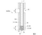
図2は、光ファイバ10の先端部を示す部分断面図である。図2に示すように、光ファイバ10は、ファイバ本体11と被覆部20と空隙23を有している。ファイバ本体11は、軸線Jに沿って延びており、中心に位置するファイバコア11Aと、ファイバコア11Aの外周面を被覆するファイバコア11Bとを有している。本実施形態の光ファイバ10は、ファイバコア11Aがシリカで形成され、ファイバクラッド11Bが合成樹脂で形成されている。 The tip side of the
Fig. 2 is a partial cross-sectional view showing the tip portion of the
ファイバクラッド11Bとしては、一例として、メタクリル樹脂、ポリカーボネート樹脂(PC)、ポリスチレン樹脂(PS)、アクリル樹脂、フッ素系樹脂等を用いることができる。ファイバクラッド11Bの直径としては、一例として、230μmである。ファイバクラッド11Bの屈折率は、ファイバコア11Aの屈折率よりも小さい。従って、パッチケーブルc2を介してファイバコア11Aに入射した励起光は、ファイバコア11Aを介して伝送される。As an example of the fiber clad 11B, methacrylic resin, polycarbonate resin (PC), polystyrene resin (PS), acrylic resin, fluorine-based resin, etc. can be used. As an example of the diameter of the fiber clad 11B, it is 230 μm. The refractive index of the fiber clad 11B is smaller than the refractive index of the
ファイバコア11Aは、励起光を出射する出射部12を有している。出射部12は、ファイバコア11Aの先端面である。The
被覆部20は、ファイバクラッド11Bの外周面を被覆する。被覆部20の直径としては、一例として、500μmである。被覆部20は、一例としてフッ素系樹脂で形成されている。なお、ファイバ本体11の外周面を被覆するクラッドを設ける構成であってもよい。The
被覆部20は、空隙形成部21と分断部22とを有している。空隙形成部21は、出射部12よりも軸線J方向の先端側に、軸線Jを含み外部に開口する空隙23を形成する。本実施形態における空隙23は、出射部12に臨み軸線J方向の先端側に開口している。従って、空隙23は、光ファイバ10を非貫通である。空隙形成部21は、空隙23を形成する筒状壁24を有している。筒状壁24は、軸線Jを中心として、ファイバ本体11(ファイバクラッド11B)よりも径方向外側に位置し全周に亘って筒状に形成されている。筒状壁24は、被覆部20においてファイバコア11Aの出射部12よりも光軸方向の先端側に延出する領域である。The
分断部22は、出射部12よりも基端側において被覆部20が長さ方向(軸線J方向)で分断されファイバ本体11が露出する領域である。軸線J方向に関して、出射部12から筒状壁24の先端までの長さL1と、分断部22の長さL2とは同一である。すなわち、筒状壁24は、分断部22の基端側の位置で被覆部20を軸線J方向に分割し、分割された先端側の被覆部20をファイバ本体11に対して距離L1だけ先端側に移動させることにより形成されている。The dividing
発光部30は、空隙23に位置する。発光部30は、検出対象物と反応したときに発光強度が変化する発光センサを有している。発光センサは、検出装置1により検出する対象物に応じて選択される。以下、複数の実施形態の発光センサを説明する。The light-emitting
[発光センサの第1実施形態]
発光部30は、ハイドロゲル31内に内包され第1実施形態の発光センサを含む細胞32を有している。本実施形態における発光センサは、励起光の照射により蛍光を発光するとともに、対象物と反応したときに蛍光の発光強度が変化する蛍光センサである。細胞32は、ノルアドレナリン(ノルエピネフリン)に応答して蛍光強度が増大するタンパク質センサを細胞膜上に有する。タンパク質センサは、ノルアドレナリンの受容体を遺伝子改変することによって、蛍光発光部位として蛍光タンパク質(XFP)を挿入することによって作製される。なお、タンパク質センサは、細胞の内部にあってもよい。[First embodiment of the luminescence sensor]
The light-emitting
蛍光発光部位としては、TurboGFP、AcGFP、TagGFP、Azami-Green、ZsGreen、EmGFP、EGFP、GFP2、HyPer等の緑色蛍光タンパク質(Green Fluorescent Protein, GFP);EBFP等の青色蛍光タンパク質(Blue Fluorescent Proten, BFP ); ECFP、TagCFP、AmCyan、MidoriishiCyan等のシアン蛍光タンパク質(Cyan Fluorescent Protein, CFP);TurboRFP、DsRed-Express、DsRed2、TagRFP、DsRed-Monomer、AsRed2、mStrawberry等赤色蛍光タンパク質(Red Fluorescent Protein, RFP);TagYFP、EYFP、Venus、PhiYFP、PhiYFP-m、TurboYFP、ZsYellow、mBanana等の黄色蛍光タンパク質(Yellow Fluorescent Protein, YFP)、KusabiraOrange、mOrange等の橙色蛍光タンパク質、TurboFP602、mRFP1、JRed、KillerRed、mCherry、HcRed、KeimaRed mRasberry、mPlum等の赤外光の蛍光を発する蛍光タンパク質が挙げられる。Fluorescent sites include green fluorescent proteins (GFP) such as TurboGFP, AcGFP, TagGFP, Azami-Green, ZsGreen, EmGFP, EGFP, GFP2, and Hyper; blue fluorescent proteins (BFP) such as EBFP; cyan fluorescent proteins (Cyan Fluorescent Proteins) such as ECFP, TagCFP, AmCyan, and MidoriishiCyan. Red fluorescent proteins (RFP) such as TurboRFP, DsRed-Express, DsRed2, TagRFP, DsRed-Monomer, AsRed2, and mStrawberry; yellow fluorescent proteins (Yellow Fluorescent Proteins) such as TagYFP, EYFP, Venus, PhiYFP, PhiYFP-m, TurboYFP, ZsYellow, and mBanana. Examples of such fluorescent proteins include orange fluorescent proteins such as YFP, KusabiraOrange, and mOrange, and fluorescent proteins that emit infrared fluorescence such as TurboFP602, mRFP1, JRed, KillerRed, mCherry, HcRed, KeimaRed, mRasberry, and mPlum.
ハイドロゲル31は、湿潤(膨潤)したときに空隙23に保持されることを考慮して、含水し易い材料であることが好ましい。ハイドロゲル31の成分としては、メチルセルロースもしくはデキストランなどの多糖類、(メタ)アクリルアミド、メチロールアクリルアミド、もしくはヒドロキシエチルアクリレート等のモノマーを重合して作製するアクリル系ハイドロゲル、またはポリエチレングリコールとジイソシアネートから作製するウレタン系ハイドロゲルなどを用いることができ、上記で例示したものに加えて、例えば、ポリビニルアルコール、ポリエチレングリコール、ポリヒドロキシアルカノエート、ポリ‐(ヒドロキシエチルメタクリレート)、ポリ‐(ヒドロキシエチルアクリレート)、ポリビニルピロリドン、ポリ‐(エチレン‐コ‐ビニルアルコール)、ポリ‐(酢酸ビニル‐コ‐ビニルアルコール)、ポリ(エチレン‐コ‐酢酸ビニル‐コ‐ビニルアルコール)、ポリ(エチレングリコール‐コ‐プロピレングリコール)、コラーゲンやゼラチンなどの生体高分子などを用いることもできる。The
図3は、上記のファイバセンサFSを製作する手順を示す概略的な斜視図である。
図3に示すように、ファイバセンサFSを製作する際には、細胞32を内包するハイドロゲル31内に光ファイバ10の先端を浸漬した状態で、被覆部20の先端側の一部を分割してファイバ本体11に対して先端側に移動させる。被覆部20の先端側の一部を先端側に移動させる際には、例えば、被覆部20の分割位置に切れ目を形成しておき、当該先端側の一部をファイバ本体11に対して引き抜く方法を採ることができる。このとき、被覆部20は、フッ素系樹脂で形成されており摩擦抵抗が小さいため、被覆部20を容易に引き抜くことができる。 FIG. 3 is a schematic perspective view showing a procedure for manufacturing the above-mentioned fiber sensor FS.
3, when fabricating the fiber sensor FS, a portion of the tip side of the
被覆部20の先端側の一部を先端側に移動させることにより、出射部12よりも先端側に、空隙形成部21(筒状壁24)により囲まれ、出射部12に臨み軸線J方向の先端側に開口する空隙23が形成される。空隙23は、被覆部20に対してファイバ本体11が相対的に基端側に移動することにより形成されているため、ファイバ本体11と同一径(例えば、230μm)の円柱状である。By moving a portion of the tip side of the
空隙23の深さ(距離L1)としては、大きすぎる場合には、空隙23における細胞32と出射部12との距離が大きくなり細胞32からの蛍光検出の精度が低下する可能性がある。一方、空隙23の深さ(距離L1)が小さい場合には、空隙23に細胞32を十分に保持できない可能性がある。そのため、空隙23の深さ(距離L1)としては、20μm以上、1000μm以下であることが好ましい。If the depth (distance L1) of the
また、被覆部20に対してファイバ本体11が相対的に基端側に移動することにより形成された空隙23が負圧となるため、空隙23には、細胞32を内包するハイドロゲル31が開口を介して導入されて充填される。ここで、空隙23は、全周に亘って筒状に形成された筒状壁24に囲まれているため、細胞32は空隙23において一様に拡散している。In addition, the
その結果、先端に空隙23が形成され、当該空隙23に一様に拡散している発光部30としての細胞32を内包するハイドロゲル31が充填された光ファイバ10が製作される。そして、当該光ファイバ10を先端側から挿入具10Aの中心穴に挿通することにより、ファイバセンサFSが製作される。As a result, a
なお、先端に空隙23を形成し、空隙23に発光部30を設けた後に光ファイバ10を挿入具10Aの中心穴に挿通する手順の他に、挿入具10Aの中心穴に挿通した光ファイバ10に対して、上述した手順により、空隙23を形成するとともに、当該空隙23に発光部30を設ける手順を選択することも可能である。In addition to the procedure of forming a
上記構成の検出装置1を用いて生体内の生理活性物質を検出する際には、まず、生体内にファイバセンサFSを挿入する。生体内にファイバセンサFSが挿入された後に、光源部40から励起光を発光させる。なお、励起光の発光は、ファイバセンサFSを生体内に挿入する前から行ってもよい。When detecting a physiologically active substance in a living organism using the
励起光は、パッチケーブルc1を介してダイクロイックミラー50に入射して反射され、パッチケーブルc2を介して光ファイバ10に入射する。光ファイバ10に入射した励起光は、ファイバ本体11を透過し軸線Jに沿って出射部12から出射する。出射部12から出射した励起光は、発光部30における細胞32を照射する。The excitation light is incident on the
励起光に照射された細胞32は、タンパク質センサが励起光の波長に応じた波長の蛍光を発光する。細胞32で生じた蛍光の一部は、ファイバ本体11に入射した後にパッチケーブルc2を介してダイクロイックミラー50に入射して透過する。ダイクロイックミラー50を透過した蛍光の画像は、光検出器60により撮像される。光検出器60が撮像した蛍光画像の信号は、前置増幅器70で増幅され、ロックインアンプ80でノイズを除去された後に検出部90に送出される。検出部90は、入力した信号に基づき、例えば、細胞32が生体内の生理活性物質と反応しない状態における細胞32からの蛍光情報としてモニターする。When the
一方、細胞32が空隙23の開口を介して生体内の生理活性物質の分子と反応する(接する)と、細胞32におけるタンパク質センサの蛍光発光特性が変化することにより、蛍光の発光強度が変化する。その結果、検出部90が検出する細胞32からの蛍光強度が変化する。ここで、蛍光発光特性の変化は、細胞32が生理活性物質と反応してから一定時間後に信号値が変化(上昇)し始めた後に真の測定値に達するが、細胞32が空隙23で一様に拡散しており、空隙23は極めて小さいため、生理活性物質が直ちに空隙23に一様に拡散することにより、早いレスポンスで蛍光強度の変化を検出することができる。検出部90は、モニターする蛍光強度の変化を検出することにより、生体内の生理活性物質を検出することができる。On the other hand, when the
以上説明したように、本実施形態のファイバセンサFSおよび検出装置1では、ファイバ本体11の先端側に励起光の軸線Jを含み外部に開口する空隙23が設けられ、対象物と反応したときに蛍光の発光強度が変化する蛍光センサを含む発光部30が空隙23に設けられている。そのため、本実施形態のファイバセンサFSおよび検出装置1では、分子の酸化還元反応を用いて検出する方法で生じる酸化還元電位の近い分子を区別するのが難しいという問題や、液体クロマトグラフィーを用いて検出する方法で生じる分離に時間がかかるという問題、上記の非特許文献1に記載された手法で生じる時間や手間が掛かるという問題を解消して、時間や手間が掛かることなく検出対象物を検出することが可能になる。As described above, in the fiber sensor FS and
また、本実施形態のファイバセンサFSおよび検出装置1では、軸線Jを中心として、ファイバ本体11よりも径方向外側に位置し全周に亘って筒状に形成された筒状壁24により空隙23を形成しているため、空隙23において細胞32を一様に拡散させることができる。そのため、本実施形態のファイバセンサFSおよび検出装置1では、空隙23を形成する隔壁の一部が切り欠かれ細胞32の拡散が一様でない場合のように、出射部12の直近から離れた位置の細胞32からの蛍光信号に基づき対象物を検出することで、対象物検出する際のレスポンスが遅くなってしまうことを回避できる。In addition, in the fiber sensor FS and
さらに、本実施形態のファイバセンサFSおよび検出装置1では、空隙23が開口部を有するものの光ファイバ10を非貫通であり、空隙23に保持した発光部30が開口部から離脱しそうになっても負圧が生じるため、空隙23が光ファイバ10を貫通している場合のように、空隙23から発光部30が離脱してしまうことを抑制できる。Furthermore, in the fiber sensor FS and
なお、上記実施形態では、蛍光センサとしてタンパク質センサを細胞膜上に発現させた細胞を用いて生理活性物質を検出する構成を例示したが、この構成に限定されない。例えば、細胞の代わりに、人工的に作ったリポソームが蛍光センサを含む構成とし、リポソームが生理活性物質と反応したときの蛍光の発光強度の変化により生理活性物質を検出する構成であってもよい。In the above embodiment, a configuration in which a physiologically active substance is detected using a cell in which a protein sensor is expressed on the cell membrane as a fluorescent sensor is exemplified, but this configuration is not limited to this. For example, instead of a cell, an artificially created liposome may contain a fluorescent sensor, and a physiologically active substance may be detected based on a change in the fluorescence emission intensity when the liposome reacts with the physiologically active substance.
[発光センサの第2実施形態]
続いて、発光センサの第2実施形態について、図4を参照して説明する。
図4において、図1乃至図3に示す発光センサの第1実施形態の構成要素と同一の要素については同一符号を付し、その説明を省略する。[Second embodiment of the light emission sensor]
Next, a second embodiment of the light-emitting sensor will be described with reference to FIG.
In FIG. 4, the same elements as those in the first embodiment of the luminescence sensor shown in FIGS. 1 to 3 are denoted by the same reference numerals, and the description thereof will be omitted.
図4に示すように、空隙23には、ハイドロゲル31内に内包されたタンパク質またはDNAプローブまたはビーズで構成される蛍光センサ32Aが発光部30における発光センサとして充填されている。タンパク質としては、例えば、上述した蛍光タンパク質(蛍光発光部位)を用いることができる。As shown in FIG. 4, the
DNAプローブとしては、例えば、一本鎖DNAが対象物(生理活性物質)を認識して部分的にハイブリダイズし、蛍光共鳴エネルギー移動(FRET)で発光するモレキュラービーコンを用いることができる。As a DNA probe, for example, a molecular beacon can be used, in which single-stranded DNA recognizes a target substance (biologically active substance), partially hybridizes with it, and emits light by fluorescence resonance energy transfer (FRET).
ビーズとしては、例えば、生理活性物質としたときに蛍光強度が変化する限り特に限定されないが、蛍光色素を含有するビーズや、蛍光染色されたビーズ等を用いることができる。The type of beads is not particularly limited as long as the fluorescence intensity changes when the beads are treated as a biologically active substance, but beads containing fluorescent dyes or fluorescently dyed beads can be used.
上記構成の蛍光センサ32Aを用いた場合、励起光に照射された蛍光センサ32Aが励起光の波長に応じた波長の蛍光を発光する。一方、蛍光センサ32Aが空隙23の開口を介して生体内の生理活性物質の分子と反応する(接する)と、蛍光センサ32Aの蛍光発光特性が変化することにより、蛍光の発光強度が変化する。そして、検出部90が、モニターする蛍光強度の変化を検出することにより、上記第1実施形態の蛍光センサを用いた場合と同様に、生体内の生理活性物質を検出することができる。When the
[発光センサの第3実施形態]
続いて、発光センサの第3実施形態について説明する。
上記発光センサの第1、第2実施形態では、生理活性物質に応答して蛍光強度が増大するタンパク質センサを蛍光センサとして用いる構成を例示したが、生理活性物質に応答してCa2+等のイオンの流入を引き起こすタンパク質を細胞膜上または細胞の内部に有するとともに、流入したイオンに応答して蛍光強度が変化する蛍光インジケータを蛍光センサ32Aとして有する構成を採ることができる。[Third embodiment of the luminescence sensor]
Next, a third embodiment of the light-emitting sensor will be described.
In the first and second embodiments of the luminescence sensor described above, a configuration has been exemplified in which a protein sensor whose fluorescence intensity increases in response to a physiologically active substance is used as the fluorescent sensor, but a configuration can also be adopted in which a protein that causes an influx of ions such as Ca2+ in response to a physiologically active substance is present on the cell membrane or inside the cell, and the
上記イオンの流入を引き起こすタンパク質としては、例えばムスカリン受容体などのアセチルコリン受容体を含むGタンパク質共役受容体の一群を用いることができる。
上記蛍光インジケータとしては、例えばカルシウムイオン指示薬fura-2やindo-1、fluo-3、rhod-2およびこれらのファミリーなどを用いることができる。 As the protein that induces the influx of ions, for example, a group of G protein-coupled receptors including acetylcholine receptors such as muscarinic receptors can be used.
As the fluorescent indicator, for example, calcium ion indicator fura-2, indo-1, fluo-3, rhod-2 and members of the family thereof can be used.
上記構成の蛍光センサ32Aを用いた場合、励起光に照射された蛍光センサ32Aが励起光の波長に応じた波長の蛍光を発光する。一方、タンパク質が空隙23の開口を介して生体内の生理活性物質と反応して流入したイオンに応答して、蛍光インジケータの蛍光発光特性が変化することにより、蛍光の発光強度が変化する。そして、検出部90が、モニターする蛍光強度の変化を検出することにより、生体内の生理活性物質を検出することが可能になる。When the
なお、上記生理活性物質に応答してイオンの流入を引き起こすタンパク質と、流入したイオンに応答する蛍光インジケータとを用いる構成は、細胞の代わりにリポソームを用いる場合にも同様に生体内の生理活性物質を検出することが可能になる。The configuration using a protein that induces an influx of ions in response to the above-mentioned physiologically active substance and a fluorescent indicator that responds to the influx of ions also makes it possible to detect physiologically active substances in the living body when liposomes are used instead of cells.
[発光センサの第4実施形態]
続いて、発光センサの第4実施形態について説明する。
上記発光センサの第1~第3実施形態では、励起光の照射により蛍光が発光するとともに、生理活性物質に応答して蛍光強度が増大する蛍光センサを用いる構成を例示したが、例えば、対象物と反応する前は発光せず、対象物と反応したときに発光することで発光強度が変化する物質を発光センサとして用いる構成であってもよい。この場合、検出装置1においては、励起光の光源が不要となる。[Fourth embodiment of the luminescence sensor]
Next, a fourth embodiment of the luminescence sensor will be described.
In the first to third embodiments of the luminescence sensor, a configuration has been exemplified in which a fluorescent sensor emits fluorescence when irradiated with excitation light and whose fluorescence intensity increases in response to a physiologically active substance, but, for example, a configuration may be used in which a substance that does not emit light before reacting with a target substance and emits light when reacting with the target substance, thereby changing the luminescence intensity, is used as the luminescence sensor. In this case, the
この種の発光センサとしては、例えばホタル由来や発光バクテリア由来の発光酵素(ルシフェラーゼ)等を用いることができる。検出装置1においては、発光酵素が検出対象物となる基質分子に応答して発光した発光画像を撮像することにより、生体内の検出対象物を検出することができる。This type of luminescence sensor can use, for example, a luminescent enzyme (luciferase) derived from fireflies or luminescent bacteria. In the
上記の発光酵素は、発光酵素を発現させたタンパク質センサが空隙23におけるハイドロゲル31内に内包された細胞膜上または細胞の内部に配される構成、空隙23におけるハイドロゲル31内に内包された細胞膜上または細胞の内部に配される構成や、上記細胞の代わりにリポソームに配される構成を採ることができる。The above-mentioned luminescent enzyme can be arranged in a configuration in which a protein sensor expressing the luminescent enzyme is placed on a cell membrane or inside a cell contained in the
[ファイバセンサの第2実施形態]
続いて、ファイバセンサFSの第2実施形態について、図5および図6を参照して説明する。
これらの図において、図1乃至図3に示す第1実施形態の構成要素と同一の要素については同一符号を付し、その説明を省略する。
また、第2実施形態のファイバセンサFSにおいては、第1実施形態の蛍光センサを用いる構成を例示するが、第2、第3実施形態の蛍光センサを用いる構成にも適用可能である。[Second embodiment of fiber sensor]
Next, a second embodiment of the fiber sensor FS will be described with reference to FIGS.
In these figures, the same elements as those in the first embodiment shown in FIGS. 1 to 3 are designated by the same reference numerals, and the description thereof will be omitted.
In addition, in the fiber sensor FS of the second embodiment, a configuration using the fluorescent sensor of the first embodiment is exemplified, but it is also applicable to configurations using the fluorescent sensors of the second and third embodiments.
図5は、第2実施形態に係るファイバセンサFSにおける光ファイバ10を示す断面図である。
図5に示すように、本実施形態に係る光ファイバ10が有する空隙23は、軸線Jと交差(直交する)する方向に延びている。空隙23は、光ファイバ10の先端面よりも基端側に位置する。従って、本実施形態の空隙形成部21は、空隙23の周囲を囲むファイバ本体11および被覆部20によって構成される。また、ファイバ本体11の出射部12は、ファイバ本体11の先端面ではなく、空隙23に臨む面となる。 FIG. 5 is a cross-sectional view showing an
5, the
空隙23は、断面円形状の円柱状である。空隙23は、ファイバ本体11を貫くとともに、一端側(図5中、上側)において被覆部20に開口し他端側(図5中、下側)において非開口である。すなわち、空隙23は、光ファイバ10を非貫通に設けられている。ファイバ本体11における空隙23と、被覆部20における空隙23とは、同軸、且つ同一径で断面形状が同一である。
他の構成は、上記第1実施形態と同様である。 The void 23 is cylindrical with a circular cross section. The void 23 penetrates the
The other configurations are similar to those of the first embodiment.
上記の空隙23は、例えば、ドリル加工で形成することができる。
図6は、ドリルDを用いて光ファイバ10に空隙23を形成する手順を示す斜視図である。図6に示すように、上面側に断面V字状の溝101を有する治具100を用いる。そして、溝101に載置した光ファイバ10に対して、ドリルDにより径方向に沿って穴開け加工を行うことにより、光ファイバ10に非貫通の空隙23を形成できる。穴開けで形成された空隙23には、シリンジ等を用いて上述した発光部30を注入することによりファイバセンサFSが製作される。 The
Fig. 6 is a perspective view showing a procedure for forming a
本実施形態のファイバセンサFSでは、上記第1実施形態と同様の作用・効果が得られることに加えて、空隙23の軸線J方向の長さが短くできるため、出射部12と細胞32との距離が短くなり対象物検出する際のレスポンスを早くすることが可能になる。In the fiber sensor FS of this embodiment, in addition to obtaining the same action and effect as the first embodiment described above, the length of the
[ファイバセンサの第3実施形態]
続いて、ファイバセンサFSの第3実施形態について、図7を参照して説明する。
この図において、図1乃至図3に示す第1実施形態の構成要素と同一の要素については同一符号を付し、その説明を省略する。
また、第3実施形態のファイバセンサFSにおいては、第1実施形態の蛍光センサを用いる構成を例示するが、第2、第3実施形態の蛍光センサを用いる構成にも適用可能である。[Third embodiment of fiber sensor]
Next, a third embodiment of the fiber sensor FS will be described with reference to FIG.
In this figure, the same elements as those in the first embodiment shown in FIGS. 1 to 3 are designated by the same reference numerals, and the description thereof will be omitted.
In addition, in the fiber sensor FS of the third embodiment, a configuration using the fluorescent sensor of the first embodiment is exemplified, but it is also applicable to configurations using the fluorescent sensors of the second and third embodiments.
上記第1、第2実施形態では、光ファイバ10に加工を施すことにより、光ファイバ10の一部が空隙形成部21を構成していたが、本実施形態では、光ファイバ10に対して空隙形成部21を設ける点で上記第1、第2実施形態と相違している。In the first and second embodiments, the
図7は、第3実施形態に係るファイバセンサFSにおける光ファイバ10を示す外観斜視図である。
図7に示すように、光ファイバ10の先端には、空隙形成部21が設けられている。空隙形成部21は、円盤部21Aと円筒部(筒状壁)21Bとを有している。 FIG. 7 is an external perspective view showing the
7, a
円盤部21Aは、ファイバ本体11の先端面を被覆している。円盤部21Aは、ファイバ本体11と略同一径(例えば、125μm程度)の円盤状に形成されている。円盤部21Aの厚さは、例えば、200μm程度である。The
円筒部21Bは、円盤部21Aの周縁から軸線J方向の先端側に延びる円筒状に形成されている。円盤部21Aの軸線J方向の先端側の面と、円筒部21Bの内周面とに囲まれて空隙23が形成されている。空隙23は、軸線J方向の先端側に開口する円柱状に形成されている。The
円盤部21Aおよび円筒部21Bは、一例として、上述した励起光および蛍光に対して透明または半透明であり、且つ、エネルギー光(例えば、レーザー光、紫外光)の照射(エネルギーの付与)により硬化する光硬化性樹脂で一体的に形成されている。The
上記構成の空隙形成部21は、ファイバ本体11の先端面に付着した光硬化性樹脂に対して相対的に3次元で走査(スキャニング)してエネルギー光照射部110によるエネルギー光Eの照射を複数層に亘って繰り返す3Dプリンタを用いて形成できる。図7においては、光硬化性樹脂に対してエネルギー光Eを2光子吸収させる構成であるが、シングルフォトンであってもよい。The
具体的には、円盤部21Aおよび円筒部21Bは、ファイバ本体11の先端面に付着した光硬化性樹脂に、例えば、レーザー光を集光することにより形成される。空隙形成部21によって形成された空隙23には、シリンジ等によって発光部30が注入される。
これにより、ファイバセンサFSが作製される。 Specifically, the
In this way, the fiber sensor FS is produced.
本実施形態のファイバセンサFSでは、上記第1実施形態と同様の作用・効果が得られることに加えて、レーザー光等のエネルギー光Eの集光およびスキャニングのパターンを制御することにより、任意の大きさ、形状の空隙形成部21(すなわち空隙23)を容易に形成することが可能になる。In the fiber sensor FS of this embodiment, in addition to obtaining the same action and effect as the first embodiment described above, by controlling the focusing and scanning pattern of the energy light E such as laser light, it becomes possible to easily form a gap forming portion 21 (i.e., a gap 23) of any size and shape.
なお、本実施形態では、空隙形成部21が円盤部21Aを有する構成を例示したが、この構成に限定されず、空隙形成部21が円盤部21Aを有さずに円筒部21Bのみで形成される構成であってもよい。ただし、空隙形成部21が円盤部21Aを有することにより、ファイバ本体11と空隙形成部21との接触面積が増加することでファイバ本体11と空隙形成部21との接着強度を増加させることができる。In this embodiment, the
[実施例]
以下、実施例により本発明の効果をより明らかなものとする。なお、本発明は、以下の実施例に限定されるものではなく、その要旨を変更しない範囲で適宜変更して実施することができる。[Example]
The effects of the present invention will be made clearer by the following examples. Note that the present invention is not limited to the following examples, and can be appropriately modified and implemented without departing from the gist of the present invention.
本実施例では、生化学用緩衝剤(HEPES buffer)中で神経伝達物質であるノルアドレナリン(ノルエピネフリン)を検出対象物とした。また、上述したハイドロゲルとしてコラーゲンを用い、当該コラーゲン内に内包される細胞であって、ノルアドレナリンに反応したときに、発光する蛍光強度が変化するタンパク質センサとしてGRAB-NEを有するヒト培養細胞(HEK293T)を含む発光部を用いた。ファイバセンサFSとしては、図2および図3に示した第1実施形態の構成のファイバセンサFSを用いた。In this example, the detection target was the neurotransmitter noradrenaline (norepinephrine) in a biochemical buffer (HEPES buffer). Collagen was used as the hydrogel described above, and a light-emitting section was used that included human cultured cells (HEK293T) containing GRAB-NE as a protein sensor that changes in fluorescence intensity when reacting with noradrenaline, and is encapsulated in the collagen. The fiber sensor FS used had the configuration of the first embodiment shown in Figures 2 and 3.
図8は、検出部によって検出されファイバセンサにおける発光部の蛍光画像を示す図である。図8に示すように、GRAB-NEを有するヒト培養細胞がノルアドレナリンと反応した(接して)蛍光の輝点(Sensor cells Expressing GRAB-NE)として観察することができた。Figure 8 shows a fluorescent image of the light-emitting part of the fiber sensor detected by the detection part. As shown in Figure 8, human cultured cells containing GRAB-NE reacted with (contacted with) noradrenaline and were observed as bright spots of fluorescence (sensor cells expressing GRAB-NE).
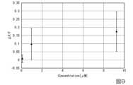
図9は、細胞のモル濃度(μM)と蛍光強度の変化との関係を示す関係図である。図9においては、10個の細胞の平均値での較正曲線が示されている。蛍光強度の変化の値(ΔF=F-F0)は、測定された蛍光強度Fで除して正規化された値である。Figure 9 is a graph showing the relationship between the molar concentration of cells (μM) and the change in fluorescence intensity. In Figure 9, a calibration curve is shown for the average value of 10 cells. The value of the change in fluorescence intensity (ΔF = F - F0) is a normalized value divided by the measured fluorescence intensity F.
図9に示されるように、濃度が数μMで10~20%の強度上昇が測定された。これにより、タンパク質センサを含む細胞によりノルアドレナリンを検出したことを確認できた。また、各細胞について蛍光強度の変化を調べると、蛍光強度が飽和するノルアドレナリンの濃度は細胞によって異なり、1~10μM程度であったが、中にはほとんど強度が変化しない細胞も存在した。このことから、ハイドロゲル中の細胞数は最低でも10個以上必要であることが示唆された。As shown in Figure 9, a 10-20% increase in intensity was measured at a concentration of several μM. This confirmed that noradrenaline was detected by cells containing the protein sensor. Furthermore, when changes in fluorescence intensity were examined for each cell, the concentration of noradrenaline at which the fluorescence intensity saturated varied from cell to cell, ranging from about 1-10 μM, although there were some cells in which the intensity hardly changed at all. This suggests that a minimum of 10 or more cells are required in the hydrogel.
図10は、ノルアドレナリンに対する特定の細胞の時間応答に関し、応答時間と蛍光強度との関係を示す関係図である。図10においては、励起光の出射部から873μm離れた位置でモル濃度が1~10μMのコラーゲン溶液に浸漬した細胞について応答時間と蛍光強度との関係が示されている。Figure 10 is a graph showing the relationship between response time and fluorescence intensity for the time response of a specific cell to noradrenaline. Figure 10 shows the relationship between response time and fluorescence intensity for a cell immersed in a collagen solution with a molar concentration of 1 to 10 μM at a position 873 μm away from the excitation light emission point.
図10に示されるように、蛍光強度の経時変化を追跡すると、蛍光強度はおよそ400秒で飽和することが確認できた。
拡散の方程式であるx=√(2Dt)を用いると、コラーゲン中のノルアドレナリンの拡散定数をDとすると、D=0.95×10⁻⁹m2s-1と推定した。この値は、水中の小分子の拡散定数と同様の値であった。これにより、より小さなハイドロゲルとデバイスについては、大幅に速い時間応答(例えば、長さ100μmのハイドロゲルで5秒応答)が期待できることを確認できた。 As shown in FIG. 10, by tracking the change in the fluorescence intensity over time, it was confirmed that the fluorescence intensity was saturated in about 400 seconds.
Using the diffusion equation x = √(2Dt), where D is the diffusion constant of noradrenaline in collagen, we estimated D = 0.95 × 10⁻⁹ m2 s-1 , which is similar to the diffusion constant of small molecules in water, confirming that for smaller hydrogels and devices, significantly faster time responses (e.g., 5 s response for a 100 μm long hydrogel) can be expected.
すなわち、図2に示した距離L1を100μmに設定することにより、蛍光強度の応答速度(変化)を5秒程度に短縮可能であることが示唆された。換言すると、検出部90による蛍光強度のモニタリングを5秒毎に設定すればノルアドレナリンの検出が可能になることが示唆された。In other words, it was suggested that by setting the distance L1 shown in FIG. 2 to 100 μm, the response speed (change) of the fluorescence intensity could be shortened to about 5 seconds. In other words, it was suggested that noradrenaline could be detected by setting the monitoring of the fluorescence intensity by the
以上、添付図面を参照しながら本発明に係る好適な実施形態について説明したが、本発明は係る例に限定されないことは言うまでもない。上述した例において示した各構成部材の諸形状や組み合わせ等は一例であって、本発明の主旨から逸脱しない範囲において設計要求等に基づき種々変更可能である。Although the preferred embodiment of the present invention has been described above with reference to the attached drawings, it goes without saying that the present invention is not limited to the examples. The shapes and combinations of the components shown in the above examples are merely examples, and various modifications can be made based on design requirements, etc., without departing from the spirit of the present invention.
例えば、上記実施形態では、神経伝達分子としてノルアドレナリンを検出する構成を例示したが、ノルアドレナリンの他にセロトニン、ドーパミン等を検出することも可能である。この場合、各神経伝達分子との反応により蛍光の発光強度が変化する蛍光センサを選択すればよい。For example, in the above embodiment, a configuration for detecting noradrenaline as a neurotransmitter molecule was exemplified, but it is also possible to detect serotonin, dopamine, etc. in addition to noradrenaline. In this case, a fluorescent sensor whose fluorescence emission intensity changes upon reaction with each neurotransmitter molecule may be selected.
また、上記実施形態では、生理活性物質として神経伝達分子を検出する構成を例示したが、神経伝達分子の他に血液または体液中のアナライト(例えば、グルコース等の糖類やpH、コレステロール、タンパク質等)を検出する構成であってもよい。
発光部30としては、上述したハイドロゲルが蛍光センサを含む構成であってもよい。蛍光センサは、検出対象物の生理活性物質との反応により蛍光の発光強度が変化するものを選択すればよい。 In addition, in the above embodiment, a configuration for detecting neurotransmitter molecules as physiologically active substances is exemplified, but the configuration may also be such that analytes in blood or body fluids (e.g., sugars such as glucose, pH, cholesterol, proteins, etc.) are detected in addition to neurotransmitter molecules.
The above-mentioned hydrogel may include a fluorescent sensor as the light-emitting
例えば、蛍光センサを含むハイドロゲルを用いてグルコース等の糖類を検出する場合、蛍光センサとして、ルテニウム有機錯体、蛍光フェニルボロン酸誘導体、または蛋白と結合したフルオレセイン等のグルコースと可逆結合する物質を用いることができる。また、ルテニウム有機錯体のルテニウムに代えてオスミウム、イリジウム、ロジウム、レニウムおよびクロム等の有機錯体を用いることができる。なお蛍光フェニルボロン酸誘導体としては、特に2つのフェニルボロン酸と蛍光残基としてアントラセンを含む化合物が、検出感度を高くできる。この他に、適切な検出技術として、蛍光共鳴エネルギー移動(フェルスター共鳴エネルギー移動、FRET)、蛍光エネルギー移動、蛍光偏光、蛍光消光、リン光、ルミネセンス増強、ルミネセンス消光があげられる。特に、供与体(D)-受容体(A)のエネルギー移動を利用したFRETを適用した発光法が好ましく、グルコースを検出する場合は、供与体(D)を結合させたレクチン(ConA)と受容体(A)を結合させたアナライト類縁体(デキストラン)が用いられる。For example, when detecting sugars such as glucose using a hydrogel containing a fluorescent sensor, the fluorescent sensor can be a substance that reversibly binds to glucose, such as a ruthenium organic complex, a fluorescent phenylboronic acid derivative, or fluorescein bound to a protein. In addition, instead of ruthenium in the ruthenium organic complex, an organic complex of osmium, iridium, rhodium, rhenium, or chromium can be used. As a fluorescent phenylboronic acid derivative, a compound containing two phenylboronic acids and anthracene as a fluorescent residue can particularly increase the detection sensitivity. Other suitable detection techniques include fluorescence resonance energy transfer (Förster resonance energy transfer, FRET), fluorescence energy transfer, fluorescence polarization, fluorescence quenching, phosphorescence, luminescence enhancement, and luminescence quenching. In particular, a luminescence method that applies FRET, which utilizes energy transfer between a donor (D) and an acceptor (A), is preferred, and when detecting glucose, a lectin (ConA) bound to a donor (D) and an analyte analog (dextran) bound to an acceptor (A) are used.
また、上記実施形態では、一種類の生理活性物質を検出する構成を例示したが、この構成に限定されず、複数種類の生理活性物質を検出する構成としてもよい。例えば、ノルアドレナリンとドーパミンとを検出する場合、ノルアドレナリンとの反応により蛍光の発光強度が変化する第1の蛍光センサと、ドーパミンとの反応により蛍光の発光強度が変化する第2の蛍光センサとを有する細胞(またはリポソームやハイドロゲル)を発光部として用いればよい。In addition, in the above embodiment, a configuration for detecting one type of physiologically active substance is exemplified, but this configuration is not limited to the above, and a configuration for detecting multiple types of physiologically active substances may be used. For example, when detecting noradrenaline and dopamine, a cell (or a liposome or a hydrogel) having a first fluorescent sensor whose fluorescent emission intensity changes upon reaction with noradrenaline and a second fluorescent sensor whose fluorescent emission intensity changes upon reaction with dopamine may be used as the light-emitting unit.
この場合、第1の蛍光センサと第2の蛍光センサとの蛍光の波長帯域が同じ(または重なる)であると、検出部90で検出した生理活性物質を区別できなくなる可能性がある。そのため、第1の蛍光センサと第2の蛍光センサとは、生理活性物質の一つと反応したときに互いに異なる波長帯域の蛍光を発光する構成とし、光源部が発光する励起光の波長帯域を第1の蛍光センサが発光する蛍光の波長帯域に対応した第1の励起光と、第2の蛍光センサが発光する蛍光の波長帯域に対応した第2の励起光とを切り替え可能な構成とすればよい。この場合、上述した検出部90による蛍光強度のモニタリングを、2.5秒ごとに第1の励起光と第2の励起光とを交互に切り替えつつ実施すれば、各生理活性物質をそれぞれ5秒ごとに連続的にモニタリングすることが可能になる。In this case, if the wavelength bands of the fluorescence of the first and second fluorescent sensors are the same (or overlap), it may be impossible to distinguish between the physiologically active substances detected by the
また、上記実施形態では、内因性の生理活性物質を検出する構成を例示したが、この構成に限定されず、例えば、外因性の物質を検出対象物として検出することも可能である。外因性の検出対象物としては、例えば、臭い物質、味覚物質、薬物等を挙げることができる。この場合、蛍光センサとしては、外因性の物質の受容体を含む物質(例えば、嗅覚受容体、味覚受容体、薬物受容体等)を用いればよい。In addition, in the above embodiment, a configuration for detecting endogenous physiologically active substances is exemplified, but the present invention is not limited to this configuration, and it is also possible to detect exogenous substances as detection targets. Examples of exogenous detection targets include odorous substances, taste substances, drugs, etc. In this case, a substance that includes a receptor for the exogenous substance (e.g., an olfactory receptor, a taste receptor, a drug receptor, etc.) can be used as the fluorescent sensor.
1…検出装置、 10…光ファイバ、 11…ファイバ本体、 11A…ファイバコア、 11B…ファイバクラッド、 12…出射部、 20…被覆部、 21…空隙形成部、 21B…円筒部(筒状壁)、 22…分断部、 23…空隙、 24…筒状壁、 30…発光部、 31…ハイドロゲル、 32…細胞、 32A…蛍光センサ、 60…光検出器(撮像部)、 90…検出部、 FS…ファイバセンサ、 J…光軸1...detection device, 10...optical fiber, 11...fiber body, 11A...fiber core, 11B...fiber clad, 12...emission section, 20...covering section, 21...void forming section, 21B...cylindrical section (cylindrical wall), 22...severing section, 23...void, 24...cylindrical wall, 30...light emitting section, 31...hydrogel, 32...cell, 32A...fluorescence sensor, 60...photodetector (imaging section), 90...detection section, FS...fiber sensor, J...optical axis
Claims (14)
Translated fromJapanese前記ファイバ本体の先端側に、前記ファイバ本体の軸線を含み外部に開口する空隙を形成する空隙形成部と、
前記空隙に位置し発光可能な発光部と、
を備え、
前記発光部は、前記対象物と反応したときに発光強度が変化する発光センサを含み、
前記空隙形成部は、前記軸線を中心として、前記ファイバ本体よりも径方向外側に位置し全周に亘って筒状に形成された筒状壁を有し、
前記光ファイバは、長さ方向で前記被覆部が分断され前記ファイバ本体が露出する分断部を有し、
前記筒状壁は、分断された前記被覆部が前記ファイバ本体の先端側に移動して形成されたものであり、
前記長さ方向で前記分断部の長さは、前記出射部から前記筒状壁の先端までの長さと同一である、ファイバセンサ。 A fiber sensor for detecting an object using an optical fiber having a fiber body provided with an emission part for emitting excitation light and a coating part for coating the fiber body,
a gap forming portion that forms a gap including an axis of the fiber body and opening to the outside, on a tip side of the fiber body;
a light-emitting portion located in the gap and capable of emitting light;
Equipped with
the light emitting unit includes a light emitting sensor whose light emission intensity changes when reacting with the object,
the gap forming portion has a cylindrical wall that is positioned radially outward from the fiber body and is formed in a cylindrical shape around the entire circumference with the axis as the center,
the optical fiber has a division portion where the coating portion is divided in a longitudinal direction to expose the fiber body,
the cylindrical wall is formed by moving the divided coating portion toward the tip side of the fiber body,
A fiber sensor, wherein the length of the divided portion in the longitudinal direction is the same as the length from the emission portion to the tip of the cylindrical wall.
前記ファイバ本体は、中心に位置するファイバコアと、前記ファイバコアの外周面を被覆するファイバクラッドとを有し、
前記被覆部は、前記ファイバクラッドの外周面を被覆し、
前記ファイバ本体の先端側に、前記ファイバ本体の軸線を含み外部に開口する空隙を形成する空隙形成部と、
前記空隙に位置し発光可能な発光部と、
を備え、
前記発光部は、前記対象物と反応したときに発光強度が変化する発光センサを含み、
前記空隙形成部は、前記軸線と交差する方向に延びる前記空隙を形成し、
前記空隙は、前記光ファイバの先端側の端面よりも基端側の位置で前記ファイバ本体を貫くとともに、前記被覆部において開口する、ファイバセンサ。 A fiber sensor for detecting an object using an optical fiber having a fiber body provided with an emission part for emitting excitation light and a coating part for coating the fiber body,
The fiber body has a fiber core located at the center and a fiber clad covering an outer circumferential surface of the fiber core,
the coating portion coats an outer peripheral surface of the fiber clad,
a gap forming portion that forms a gap including an axis of the fiber body and opening to the outside, on a tip side of the fiber body;
a light-emitting portion located in the gap and capable of emitting light;
Equipped with
the light emitting unit includes a light emitting sensor whose light emission intensity changes when reacting with the object,
The gap forming portion forms the gap extending in a direction intersecting the axis,
The gap penetrates the fiber body at a position closer to the base end than the end face of the tip end of the optical fiber, and opens in the coating.
請求項2記載のファイバセンサ。The covering portion is formed of a resin.
The fiber sensor according to claim2 .
前記細胞は、前記発光センサを内部または細胞膜上に有する、
請求項1から3のいずれか一項に記載のファイバセンサ。 the light-emitting unit has cells encapsulated in a hydrogel;
The cell has the luminescence sensor inside or on the cell membrane.
The fiber sensor according to claim 1 .
請求項4記載のファイバセンサ。 The luminescence sensor is a protein contained in the cell.
The fiber sensor according to claim 4.
請求項4記載のファイバセンサ。 The cell has a protein that causes an influx of a predetermined ion when reacting with the target substance, and a fluorescent indicator that changes in fluorescence emission intensity in response to the ion as the luminescence sensor.
The fiber sensor according to claim 4.
前記リポソームは、前記発光センサを含む、
請求項1から3のいずれか一項に記載のファイバセンサ。 the light-emitting unit has liposomes encapsulated in a hydrogel,
The liposome contains the luminescence sensor.
The fiber sensor according to claim 1 .
請求項1から3のいずれか一項に記載のファイバセンサ。 The light emitting unit has a hydrogel including the light emitting sensor.
The fiber sensor according to claim 1 .
請求項1から3のいずれか一項に記載のファイバセンサ。 The light-emitting unit has a protein encapsulated in a hydrogel as the light-emitting sensor.
The fiber sensor according to claim 1 .
請求項1から3のいずれか一項に記載のファイバセンサ。 The light emitting unit includes a DNA probe as the light emitting sensor contained in a hydrogel.
The fiber sensor according to claim 1 .
請求項1記載のファイバセンサ。 The cylindrical wall is formed of a hardening material that is hardened by application of energy.
The fiber sensor according to claim 1.
請求項1から11のいずれか一項に記載のファイバセンサ。 The void does not penetrate the optical fiber.
The fiber sensor according to any one of claims 1 to 11.
請求項1から12のいずれか一項に記載のファイバセンサ。 The target substance is a physiologically active substance.
A fiber sensor according to any one of claims 1 to 12.
前記発光部からの発光画像を前記光ファイバを介して撮像する撮像部と、
撮像した前記発光画像に基づいて前記対象物を検出する検出部と、
を有する検出装置。 A fiber sensor according to any one of claims 1 to 13;
an imaging unit that captures an image of light emitted from the light emitting unit through the optical fiber;
a detection unit that detects the object based on the captured luminescence image;
A detection device having the following:
Priority Applications (1)
| Application Number | Priority Date | Filing Date | Title |
|---|---|---|---|
| JP2020091751AJP7613709B2 (en) | 2020-05-26 | 2020-05-26 | Fiber optic sensors and detectors |
Applications Claiming Priority (1)
| Application Number | Priority Date | Filing Date | Title |
|---|---|---|---|
| JP2020091751AJP7613709B2 (en) | 2020-05-26 | 2020-05-26 | Fiber optic sensors and detectors |
Publications (2)
| Publication Number | Publication Date |
|---|---|
| JP2021188942A JP2021188942A (en) | 2021-12-13 |
| JP7613709B2true JP7613709B2 (en) | 2025-01-15 |
Family
ID=78849282
Family Applications (1)
| Application Number | Title | Priority Date | Filing Date |
|---|---|---|---|
| JP2020091751AActiveJP7613709B2 (en) | 2020-05-26 | 2020-05-26 | Fiber optic sensors and detectors |
Country Status (1)
| Country | Link |
|---|---|
| JP (1) | JP7613709B2 (en) |
Families Citing this family (1)
| Publication number | Priority date | Publication date | Assignee | Title |
|---|---|---|---|---|
| CN114636681A (en)* | 2022-02-25 | 2022-06-17 | 清华大学 | Optical fiber biosensing probe and preparation method thereof |
Citations (5)
| Publication number | Priority date | Publication date | Assignee | Title |
|---|---|---|---|---|
| JP2004521323A (en) | 2001-03-27 | 2004-07-15 | サラフスカイ,ジョシュア,エス. | Method and apparatus for detecting probe-target interactions using surface selective nonlinear optical techniques |
| JP2008517299A (en) | 2004-10-19 | 2008-05-22 | ベクトン・ディキンソン・アンド・カンパニー | Optical fiber device for detecting analyte and manufacturing method thereof |
| JP2008196940A (en) | 2007-02-13 | 2008-08-28 | Hamamatsu Univ School Of Medicine | Biosensor type imaging fiber device |
| JP2008292471A (en) | 2007-04-23 | 2008-12-04 | Tatsuta Electric Wire & Cable Co Ltd | Fiber type cell, spectroscopic device, and spectroscopic measurement method |
| JP2015169486A (en) | 2014-03-05 | 2015-09-28 | 学校法人 創価大学 | Optical fiber sensor device and method of manufacturing the same |
Family Cites Families (4)
| Publication number | Priority date | Publication date | Assignee | Title |
|---|---|---|---|---|
| US5416879A (en)* | 1993-03-29 | 1995-05-16 | World Precision Instruments, Inc. | Apparatus and method for measuring light absorption in small aqueous fluid samples |
| JP3305398B2 (en)* | 1993-03-31 | 2002-07-22 | 三菱レイヨン株式会社 | Optical fiber sensor |
| US5462880A (en)* | 1993-09-13 | 1995-10-31 | Optical Sensors Incorporated | Ratiometric fluorescence method to measure oxygen |
| JPH0861988A (en)* | 1994-08-26 | 1996-03-08 | Mitsubishi Cable Ind Ltd | Optical fiber sensor |
- 2020
- 2020-05-26JPJP2020091751Apatent/JP7613709B2/enactiveActive
Patent Citations (5)
| Publication number | Priority date | Publication date | Assignee | Title |
|---|---|---|---|---|
| JP2004521323A (en) | 2001-03-27 | 2004-07-15 | サラフスカイ,ジョシュア,エス. | Method and apparatus for detecting probe-target interactions using surface selective nonlinear optical techniques |
| JP2008517299A (en) | 2004-10-19 | 2008-05-22 | ベクトン・ディキンソン・アンド・カンパニー | Optical fiber device for detecting analyte and manufacturing method thereof |
| JP2008196940A (en) | 2007-02-13 | 2008-08-28 | Hamamatsu Univ School Of Medicine | Biosensor type imaging fiber device |
| JP2008292471A (en) | 2007-04-23 | 2008-12-04 | Tatsuta Electric Wire & Cable Co Ltd | Fiber type cell, spectroscopic device, and spectroscopic measurement method |
| JP2015169486A (en) | 2014-03-05 | 2015-09-28 | 学校法人 創価大学 | Optical fiber sensor device and method of manufacturing the same |
Non-Patent Citations (1)
| Title |
|---|
| Kristin Weidemaier et al.,Multi-day pre-clinical demonstration of glucose/galactose binding protein-based fiber optic sensor,Biosensors and Bioelectronics,2011年,Vol.26,pp.4117-4123 |
Also Published As
| Publication number | Publication date |
|---|---|
| JP2021188942A (en) | 2021-12-13 |
Similar Documents
| Publication | Publication Date | Title |
|---|---|---|
| Du et al. | Hydrogel-based optical ion sensors: Principles and challenges for point-of-care testing and environmental monitoring | |
| Liebsch et al. | Fluorescent imaging of pH with optical sensors using time domain dual lifetime referencing | |
| Wang et al. | A selected review of recent advances in the study of neuronal circuits using fiber photometry | |
| Phan et al. | Measuring synaptic vesicles using cellular electrochemistry and nanoscale molecular imaging | |
| Peterman et al. | The fluorescence dynamics of single molecules of green fluorescent protein | |
| LeChasseur et al. | A microprobe for parallel optical and electrical recordings from single neurons in vivo | |
| Yotter et al. | Sensor technologies for monitoring metabolic activity in single cells-part I: optical methods | |
| Matsuda et al. | Direct measurement of protein dynamics inside cells using a rationally designed photoconvertible protein | |
| Gong et al. | A hydrogel-based optical fibre fluorescent pH sensor for observing lung tumor tissue acidity | |
| Schmälzlin et al. | An optical multifrequency phase-modulation method using microbeads for measuring intracellular oxygen concentrations in plants | |
| Murakoshi et al. | Postsynaptic signaling during plasticity of dendritic spines | |
| Lee et al. | Monitoring behaviorally induced biochemical changes using fluorescence lifetime photometry | |
| Lu et al. | Nanoscale fluorescent sensors for intracellular analysis | |
| Andrews et al. | Visualising apoptosis in live zebrafish using fluorescence lifetime imaging with optical projection tomography to map FRET biosensor activity in space and time | |
| CA2019066A1 (en) | Fluorescence-based optical sensor for detection of lipid-soluble analytes | |
| Claessen et al. | Single-biomolecule kinetics: the art of studying a single enzyme | |
| JP7613709B2 (en) | Fiber optic sensors and detectors | |
| Liu et al. | Recent development in amperometric measurements of vesicular exocytosis | |
| Frankær et al. | Investigating the time response of an optical pH sensor based on a polysiloxane–polyethylene glycol composite material impregnated with a pH-responsive triangulenium dye | |
| Amatore et al. | Remote fluorescence imaging of dynamic concentration profiles with micrometer resolution using a coherent optical fiber bundle | |
| Ueda et al. | Imaging intracellular protein interactions/activity in neurons using 2-photon fluorescence lifetime imaging microscopy | |
| Tan et al. | Photonic crystal enhancement of a homogeneous fluorescent assay using submicron fluid channels fabricated by E‐jet patterning | |
| US10871447B2 (en) | Bleaching of dyes in luminescent detection | |
| Orellana | Fluorescence-based sensors | |
| Baldini et al. | A new optical platform for biosensing based on fluorescence anisotropy |
Legal Events
| Date | Code | Title | Description |
|---|---|---|---|
| A80 | Written request to apply exceptions to lack of novelty of invention | Free format text:JAPANESE INTERMEDIATE CODE: A80 Effective date:20200527 | |
| A80 | Written request to apply exceptions to lack of novelty of invention | Free format text:JAPANESE INTERMEDIATE CODE: A80 Effective date:20200617 | |
| RD01 | Notification of change of attorney | Free format text:JAPANESE INTERMEDIATE CODE: A7426 Effective date:20200814 | |
| A521 | Request for written amendment filed | Free format text:JAPANESE INTERMEDIATE CODE: A821 Effective date:20200814 | |
| A621 | Written request for application examination | Free format text:JAPANESE INTERMEDIATE CODE: A621 Effective date:20230517 | |
| A977 | Report on retrieval | Free format text:JAPANESE INTERMEDIATE CODE: A971007 Effective date:20240105 | |
| A131 | Notification of reasons for refusal | Free format text:JAPANESE INTERMEDIATE CODE: A131 Effective date:20240130 | |
| A521 | Request for written amendment filed | Free format text:JAPANESE INTERMEDIATE CODE: A523 Effective date:20240325 | |
| A131 | Notification of reasons for refusal | Free format text:JAPANESE INTERMEDIATE CODE: A131 Effective date:20240618 | |
| A521 | Request for written amendment filed | Free format text:JAPANESE INTERMEDIATE CODE: A523 Effective date:20240809 | |
| TRDD | Decision of grant or rejection written | ||
| A01 | Written decision to grant a patent or to grant a registration (utility model) | Free format text:JAPANESE INTERMEDIATE CODE: A01 Effective date:20241119 | |
| A61 | First payment of annual fees (during grant procedure) | Free format text:JAPANESE INTERMEDIATE CODE: A61 Effective date:20241219 | |
| R150 | Certificate of patent or registration of utility model | Ref document number:7613709 Country of ref document:JP Free format text:JAPANESE INTERMEDIATE CODE: R150 |